Broch
Broch
Broch

You also want an ePaper? Increase the reach of your titles
YUMPU automatically turns print PDFs into web optimized ePapers that Google loves.
STRUCTURAL DESIGN<br />
General<br />
Building practice approximation<br />
method<br />
for calculation of<br />
cutting forces and<br />
deformations.<br />
Version 1 / 2011<br />
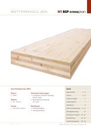
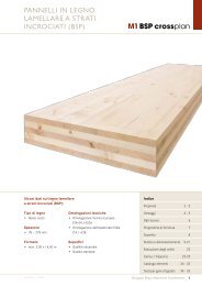
M1 BSP crossplan<br />
Components made of M1 BSP crossplan are designed and executed according to the following<br />
standards:<br />
• Design according to DIN 1052:2008 allowing for German technical approval<br />
(Z-9.1-638)<br />
or<br />
• Design according to EN 1995 (Eurocode 5) allowing for Appendices 2 to 4 of European<br />
technical approval ETA-09 / 0036<br />
The structural analysis for M1 BSP crossplan must be conducted in each individual case and<br />
the standards and regulations applicable at the site of use must be complied with.<br />
Analysis of the stress distribution and internal forces and moments must be conducted according<br />
to the composite theory allowing for shear deformations.<br />
An approximation method is required in practical use. Here, the calculation is carried out as<br />
for a beam under bending moment with fl exible joining means (Austrian standard B 4100 / 2;<br />
DIN 1052; EN 1995-1-1, Appendix B), but the shear deformation of the transverse layers is<br />
taken into consideration instead of the fl exibility of the joining means.<br />
Using this approach, it is possible to achieve a good approximation for the stress and deformation<br />
calculations.<br />
At the same time, for the actual design the moments of inertia are multiplied by a reduction<br />
factor - which takes into account the net moments of inertia and the rolling shear deformation<br />
of the transverse layers.<br />
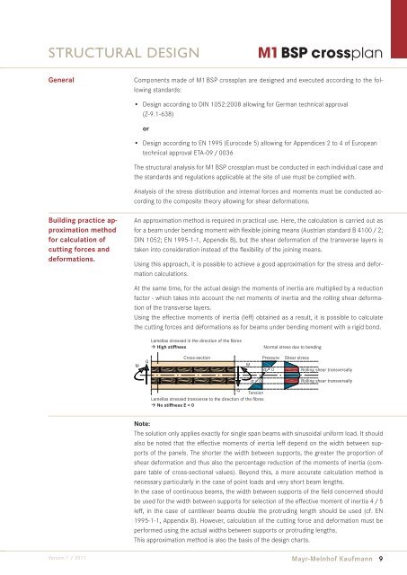
Using the eff ective moments of inertia (Ieff ) obtained as a result, it is possible to calculate<br />
the cutting forces and deformations as for beams under bending moment with a rigid bond.<br />
M Q<br />
Lamellas stressed in the direction of the fibres<br />
� High stiffness<br />
Cross-section<br />
Q<br />
Tension<br />
Lamellas stressed transverse to the direction of the fibres<br />
� No stiffness E = 0<br />
M<br />
σ = 0<br />
Normal stress due to bending<br />
Pressure<br />
σ = 0<br />
Shear stress<br />
Rolling shear transversally<br />
Rolling shear transversally<br />
Note:<br />
The solution only applies exactly for single span beams with sinusoidal uniform load. It should<br />
also be noted that the eff ective moments of inertia Ieff depend on the width between supports<br />
of the panels. The shorter the width between supports, the greater the proportion of<br />
shear deformation and thus also the percentage reduction of the moments of inertia (compare<br />
table of cross-sectional values). Beyond this, a more accurate calculation method is<br />
necessary particularly in the case of point loads and very short beam lengths.<br />
In the case of continuous beams, the width between supports of the fi eld concerned should<br />
be used for the width between supports for selection of the eff ective moment of inertia 4 / 5<br />
Ieff , in the case of cantilever beams double the protruding length should be used (cf. EN<br />
1995-1-1, Appendix B). However, calculation of the cutting force and deformation must be<br />
performed using the actual widths between supports or protruding lengths.<br />
This approximation method is also the basis of the design charts.<br />
Mayr-Melnhof Kaufmann 9