Counter & 7-Seg. Disp. Decoder
Counter & 7-Seg. Disp. Decoder
Counter & 7-Seg. Disp. Decoder

You also want an ePaper? Increase the reach of your titles
YUMPU automatically turns print PDFs into web optimized ePapers that Google loves.
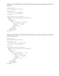
LAB-III<br />
1. Write a VHDL code to implement the circuit shown in Figure1.<br />
CLK<br />
D0<br />
S0<br />
S1<br />
7- <strong>Seg</strong>ment LED<br />
<strong>Counter</strong><br />
D1<br />
D2<br />
LED<br />
<strong>Decoder</strong><br />
S2<br />
S3<br />
S4<br />
S5<br />
S2<br />
S3<br />
S4<br />
S1<br />
D3<br />
S5<br />
S6<br />
S0<br />
Figure 1: High level diagram of <strong>Counter</strong> Implemented on the 7-<strong>Seg</strong>ment <strong>Disp</strong>lay<br />
2. Write the VHDL code for LED decoder and verify your code using the<br />
Simulation tool.<br />
3. Create a schematic symbol for LED <strong>Decoder</strong> using the “Create Schematic<br />
Symbol” option in the synthesize design step.<br />
4. Write Behavioral VHDL code for a 28 bit counter with clock as the input and the<br />
most significant 4 bits as the outputs.<br />
5. Verify your code using the simulation tool and then create a schematic symbol for<br />
the counter.<br />
6. Open the Schematic editor and then make a design using the LED decoder and<br />
the counter symbols. The input to the counter should be given using an input<br />
buffer (IBUFG). The output of the decoder is passed through and output buffer<br />
(OBUF). Using the symbols, create the complete model for an Up-counter to be<br />
displayed on a seven segment LED display.<br />
Hint: The truth table for the LED decoder is given below<br />
S6
For example: To display the Hex number 0, the bits S6S5S4S3S2S1S0= 11101112 .