Journal of Accident Investigation
Journal of Accident Investigation
Journal of Accident Investigation

You also want an ePaper? Increase the reach of your titles
YUMPU automatically turns print PDFs into web optimized ePapers that Google loves.
24 “I”-shaped stringers that span the length <strong>of</strong> the stabilizer,<br />
parallel to the aft spar. Internal stiffeners for the box consist<br />
<strong>of</strong> a center spar at the lower end <strong>of</strong> the span and 16 ribs, not<br />
including the two closure ribs. The components <strong>of</strong> the box are<br />
riveted together, and the leading edge fairings and trailing edge<br />
panels are attached with threaded fasteners.<br />
Except for the fasteners, lightning protection strips, and<br />
trailing edge panel support frames, the vertical stabilizer is<br />
made entirely <strong>of</strong> composite materials. The stiffened box <strong>of</strong><br />
the vertical stabilizer is a solid carbon-fiber reinforced polymer<br />
(CFRP) laminate composed <strong>of</strong> T300 carbon fibers in a CIBA<br />
913 epoxy matrix. The laminate includes both unidirectional<br />
tape and eight-harness satin fabric layers in the construction.<br />
The zero-degree fibers <strong>of</strong> the fabric and tape layers in the<br />
composite run parallel to the stringers and the aft spar, which<br />
are at a 33.3-degree angle aft <strong>of</strong> vertical. The leading edge<br />
fairings and the trailing edge panels are sandwich composites<br />
having a Nomex® honeycomb core with glass-fiber reinforced<br />
polymer (GFRP) facesheets for the leading edge fairings and<br />
both GFRP and CFRP facesheets for the trailing edge panels.<br />
The vertical stabilizer is attached to the fuselage primarily<br />
by six CFRP lugs (main lugs) on the lower end <strong>of</strong> the vertical<br />
stabilizer, three on either side. These lugs connect by bolts<br />
approximately 2 inches in diameter to six metal clevis fittings<br />
on the fuselage.<br />
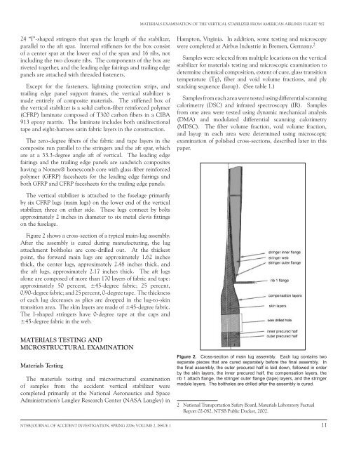
Figure 2 shows a cross-section <strong>of</strong> a typical main-lug assembly.<br />
After the assembly is cured during manufacturing, the lug<br />
attachment boltholes are core-drilled out. At the thickest<br />
point, the forward main lugs are approximately 1.62 inches<br />
thick, the center lugs, approximately 2.48 inches thick, and<br />
the aft lugs, approximately 2.17 inches thick. The aft lugs<br />
alone are composed <strong>of</strong> more than 170 layers <strong>of</strong> fabric and tape:<br />
approximately 0 percent, ±4 -degree fabric; 2 percent,<br />
0/90-degree fabric; and 2 percent, 0-degree tape. The thickness<br />
<strong>of</strong> each lug decreases as plies are dropped in the lug-to-skin<br />
transition area. The skin layers are made <strong>of</strong> ±4 -degree fabric.<br />
The I-shaped stringers have 0-degree tape at the caps and<br />
±4 -degree fabric in the web.<br />
MATERIALS TESTING AND<br />
MICROSTRUCTURAL EXAMINATION<br />
Materials Testing<br />
The materials testing and microstructural examination<br />
<strong>of</strong> samples from the accident vertical stabilizer were<br />
completed primarily at the National Aeronautics and Space<br />
Administration’s Langley Research Center (NASA Langley) in<br />
MATERIALS EXAMINATION OF THE VERTICAL STABILIZER FROM AMERICAN AIRLINES FLIGHT 87<br />
Hampton, Virginia. In addition, some testing and microscopy<br />
were completed at Airbus Industrie in Bremen, Germany. 2<br />
Samples were selected from multiple locations on the vertical<br />
stabilizer for materials testing and microscopic examination to<br />
determine chemical composition, extent <strong>of</strong> cure, glass transition<br />
temperature (Tg), fiber and void volume fractions, and ply<br />
stacking sequence (layup). (See table 1.)<br />
Samples from each area were tested using differential scanning<br />
calorimetry (DSC) and infrared spectroscopy (IR). Samples<br />
from one area were tested using dynamic mechanical analysis<br />
(DMA) and modulated differential scanning calorimetry<br />
(MDSC). The fiber volume fraction, void volume fraction,<br />
and layup in each area were determined using microscopic<br />
examination <strong>of</strong> polished cross-sections, described later in this<br />
paper.<br />
Figure 2. Cross-section <strong>of</strong> main lug assembly. Each lug contains two<br />
separate pieces that are cured separately before the final assembly. In<br />
the final assembly, the outer precured half is laid down, followed in order<br />
by the skin layers, the inner precured half, the compensation layers, the<br />
rib 1 attach flange, the stringer outer flange (tape) layers, and the stringer<br />
module layers. The boltholes are drilled after the assembly is cured.<br />
2 National Transportation Safety Board, Materials Laboratory Factual<br />
Report 02-082, NTSB Public Docket, 2002.<br />
NTSB JOURNAL OF ACCIDENT INVESTIGATION, SPRING 2006; VOLUME 2, ISSUE 1 11