DRY CELLS AND DRY BATTERIES DESCRIPTION
DRY CELLS AND DRY BATTERIES DESCRIPTION
DRY CELLS AND DRY BATTERIES DESCRIPTION

Create successful ePaper yourself
Turn your PDF publications into a flip-book with our unique Google optimized e-Paper software.
BELL SYSTEM PRACTICES<br />
Plant Series<br />
1. GENERAL<br />
1.01 This section describes the dry cells and<br />
graph plants.<br />
dry batteries used in telephone and tele<br />
1.02 This section is reissued to add the<br />
KS-15936 primary battery, to revise the<br />
information for maintenance tests and Table A.<br />
Since this reissue covers a general revision, the<br />
arrows ordinarily used to indicate changes have<br />
been omitted.<br />
1.03 A dry cell is a primary battery. It pro-<br />
duces electrical energy through an elec<br />
trochemical reaction which is not efficiently re<br />
versible except in the earlier stages of discharge.<br />
Hence, the cell when fully discharged cannot be<br />
recharged. The electrolyte is completely en<br />
closed in the absorbent materials within the cell.<br />
1.04 A dry battery is a combination of one or<br />
more dry cells electrically connected to<br />
produce electrical energy. The term battery re<br />
fers to a source of electrical energy which may<br />
be composed of one or more individual cells.<br />
2. <strong>DESCRIPTION</strong> OF APPARATUS<br />
Construction<br />
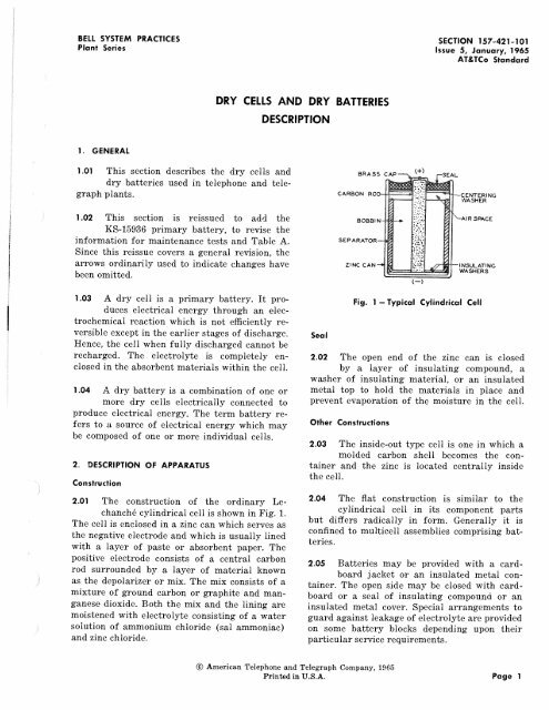
2.01 The construction of the ordinary Le-<br />
chanche cylindrical cell is shown in Fig. 1.<br />
The cell is enclosed in a zinc can which serves as<br />
the negative electrode and which is usually lined<br />
with a layer of paste or absorbent paper. The<br />
positive electrode consists of a central carbon<br />
rod surrounded by a layer of material kn0wn<br />
as the depolarizer or mix. The mix consists of a<br />
mixture of ground carbon or graphite and man<br />
ganese dioxide. Both the mix and the lining are<br />
moistened with electrolyte consisting of a water<br />
solution of ammonium chloride (sal ammoniac)<br />
and zinc chloride.<br />
<strong>DRY</strong> <strong>CELLS</strong> <strong>AND</strong> <strong>DRY</strong> <strong>BATTERIES</strong><br />
<strong>DESCRIPTION</strong><br />
Seal<br />
SEPARATOR<br />
ZINC CAN<br />
l+)<br />
SECTION 157-421-101<br />
Issue 5, January, 1965<br />
AT&TCo Standard<br />
CENTERING<br />
WASHER<br />
AIRSPACE<br />
INSULATING<br />
WASHERS<br />
Fig. 1 -Typical Cylindrical Cell<br />
2.02 The open end of the zinc can is closed<br />
by a layer of insulating compound, a<br />
washer of insulating material, or an insulated<br />
metal top to hold the materials in place and<br />
prevent evaporation of the moisture in the cell.<br />
Other Constructions<br />
2.03 The inside-out type cell is one in which a<br />
molded carbon shell becomes the con<br />
tainer and the zinc is located centrally inside<br />
the cell.<br />
2.04 The flat construction is similar to the<br />
cylindrical cell in its component parts<br />
but differs radically in form. Generally it is<br />
confined to multicell assemblies comprising bat<br />
teries.<br />
2.05 Batteries may be provided with a card-<br />
board jacket or an insulated metal con<br />
tainer. The open side may be closed with card<br />
board or a seal of insulating compound or an<br />
insulated metal cover. Special arrangements to<br />
guard against leakage of electrolyte are provided<br />
on some battery blocks depending upon their<br />
particular service requirements.<br />
©American Telephone and Telegraph Company, 1965<br />
Printed in U.S.A.<br />
Page 1
SECTION 157-421-1 01<br />
ASA Designations<br />
2.06 Cell size and batteries are designated by<br />
the American Standards Association<br />
(ASA) using the code system formulated as<br />
follows:<br />
(a) The size of cell is indicated by the ASA<br />
cell designation (letter) given in Table A.<br />
(b) Preceding the cell designation is a nu-<br />
meral showing the number of cells (or<br />
1-1/2 volt groups) in series in the battery. If<br />
no numeral appears, the battery is a 1-1/2 volt<br />
battery.<br />
(c) Following the cell designation is a nu-<br />
meral indicating the number of cells or<br />
groups of cells connected in parallel. If no<br />
such parallel-indicating number appears, it is<br />
understood that the battery consists of only<br />
a single series group. If there is a possibility<br />
of confusion between a cell designation and<br />
a parallel-indicating number, a dash will be<br />
used to separate them. Therefore, 15G2 will<br />
represent a 22-1/2 volt battery of 30 G-size<br />
cells connected 15 in series, in two parallel<br />
groups. The 15F100-2 designates a 22-1/2 volt<br />
battery of 30 F100-size cells connected 15 in<br />
series, in two parallel groups.<br />
3. THEORY OF OPERATION OF LECLANCHE CELL<br />
3.01 When the external circuit between the<br />
terminals of the cell is closed, chemical<br />
changes within the cell produce electrical<br />
energy. These changes result in the conversion<br />
of metallic zinc to one of several possible zinc<br />
compounds and the reduction of manganese di<br />
oxide. The formation and accumulation of reac<br />
tion products at the surfaces of the electrodes<br />
makes further reaction more difficult and polar<br />
izes the cell. This reduces the operating voltage<br />
and increases its apparent internal resistance.<br />
The reaction products which form at the elec<br />
trodes are slowly removed by diffusion proces<br />
ses; consequently, on open circuit the cell de<br />
polarizes and tends to return to its original<br />
voltage. When it is no longer able to deliver cur<br />
rent at a suitable voltage, the cell is considered<br />
to have reached the end of its useful life.<br />
4. OPERATING CHARACTERISTICS<br />
4.01 The life of a cell depends upon many<br />
variables such as its size, ingredients,<br />
processes of manufacture, age, and also on the<br />
Page 2<br />
frequency, duration, and rate of discharges, and<br />
the circuit voltage limits.<br />
4.02 Local internal action is responsible for<br />
the consumption of some of the chem<br />
ical energy in the cell. This loss of energy which<br />
occurs while on open circuit (either in storage<br />
or assembled in equipment) is known as shelf<br />
depreciation.<br />
Depletion<br />
4.03 The chemicals in the cell, including the<br />
water, gradually become exhausted due to<br />
useful current output and shelf depreciation.<br />
When this condition is reached, no more elec<br />
trical energy can be supplied. In order to obtain<br />
reliability of service, it is economical in most<br />
telephone applications to discard cells before<br />
their capacity is completely exhausted. However,<br />
if the cell has become exhausted due to a high<br />
rate or extended period of discharge, it may re<br />
cover to some extent if allowed to stand idle<br />
and will then be capable of rendering further<br />
service.<br />
Effect of Temperature<br />
4.04 High temperatures greatly increase shelf<br />
depreciation, and low temperatures de<br />
crease it; hence, refrigeration may be used to<br />
improve the keeping qualities of dry batteries<br />
during storage and shipment. If refrigeration is<br />
not available, batteries should be kept as cool<br />
and dry as possible.<br />
4.05 The voltage of a dry battery both on open<br />
circuit and on discharge increases with<br />
rising temperature and decreases with falling<br />
temperature. On open circuit, the change is<br />
small and can generally be disregarded. Under<br />
discharge the output obtainable is greater at a<br />
high temperature than at normal 70 F, provided<br />
the time of use does not extend over such a<br />
long period that the shelf loss is greater than<br />
the gain due to the increased chemical activity<br />
of the cell.<br />
4.06 At low temperatures, the chemical activity<br />
of the cell is decreased and long life is<br />
obtained on open-circuit and low-drain services.<br />
However, for most uses the capacity and life<br />
are greatly reduced during exposure to low
temperature. The extent of this reduction de<br />
pends upon the temperature, current drain, cut<br />
off voltage, size of cells, etc.<br />
4.07 With decreasing temperatures a condition<br />
is finally reached where the cell is unable<br />
to deliver any current. Except for grid service<br />
or very light current drain, dry batteries should<br />
be considered inoperative at temperatures of<br />
-10 F to -20 F. At 0° F, the capacity may be<br />
reduced to as little as one-fourth that at 70 F,<br />
but, as noted above, this proportion will vary<br />
widely depending on the specific conditions.<br />
4.08 Batteries subjected to low temperatures<br />
incur no permanent injury and regain<br />
their normal operating characteristics when the<br />
internal temperature again reaches normal.<br />
Since there is a considerable lag in the drop of<br />
the internal temperature, the adverse effects<br />
may be retarded by the use of thermal insula<br />
tion. Conversely, batteries once frozen require<br />
an appreciable time in which to warm up in<br />
ternally.<br />
Voltage at Which Cells or Batteries Should be<br />
Discarded (cutoff point)<br />
4.09 Batteries in low current-drain service will<br />
deliver almost all of the available ampere<br />
hour output at a relatively high operating volt<br />
age, after which the voltage drop will be com<br />
paratively rapid. Hence, in this service a high<br />
cutoff point is desirable in order to ensure re<br />
liability. For batteries in high current-drain<br />
service, the higher current will produce a greater<br />
internal resistance drop and a lower operating<br />
voltage. A lower cutoff point is therefore neces<br />
sary in order to obtain efficient use of the avail<br />
able energy contained in the cells. When it is<br />
necessary to maintain the battery voltage within<br />
close limits under high current drains, it is fre<br />
quently desirable to add one or more cells in<br />
series when the cutoff point is first reached in<br />
order to take advantage of the increased output<br />
thereby obtainable from the whole battery.<br />
Maintenance Tests<br />
4.10 In general it is desirable to replace a bat-<br />
tery before it reaches the end of its use<br />
ful life; for this reason periodic maintenance<br />
tests should be made. For many applications,<br />
specific maintenance tests have been provided<br />
ISS 5, SECTION 157-421-101<br />
on circuit schematic drawings and circuit de<br />
scription sheets to cover individual practices on<br />
standard circuits. For further information on<br />
tests and inspections refer to Section 157-421-501.<br />
5. ELECTROLYTE LEAKAGE<br />
5.01 Cells and batteries showing bulging or<br />
leaking of electrolyte or a deposit of salts<br />
on the outside should be replaced at once. Leak<br />
age of electrolyte may cause a short circuit, re<br />
sulting in dissipation of the energy of the bat<br />
tery, and may create a fire hazard.<br />
5.02 Leakage of electrolyte may be caused by<br />
any of the following factors:<br />
(a) Abnormally heavy drains or short cir<br />
cuits.<br />
(b) Damage due to handling.<br />
(c) Cells left in service after exhaustion.<br />
(d) Excessively high ambient temperatures.<br />
(e) Manufacturing defects.<br />
5.03 Factors contributing to the danger of fire<br />
due to electrolyte leakage, especially<br />
where higher capacity multiunit assemblies are<br />
used, may be:<br />
(a) Missing or damaged insulating shelf<br />
liners.<br />
(b) Battery units pushed too close together<br />
or to grounded metal shelf parts. An air<br />
space of at least 1/8 to 1/4 inch should be<br />
allowed where practical.<br />
(c) Nonstandard arrangements so that bat-<br />
teries are placed in a U formation result<br />
ing in full voltage between the two batteries<br />
at the terminal ends.<br />
(d) Battery jackets wet from an external<br />
source.<br />
5.04 For multiunit assemblies of individual<br />
cells or batteries, it is recommended that<br />
the entire battery be replaced when any one<br />
unit shows low voltage on test or shows leaking<br />
or bulging. This procedure assures that units of<br />
various ages and conditions are not connected<br />
in the same circuit so that the poorest ones may<br />
be discharged completely and develop leaking.<br />
With the following exceptions, this is a general<br />
rule. In order to maintain voltage within speci-<br />
Page 3
SECTION 157-421-101<br />
tied limits and still obtain efficient use of the<br />
battery, it may be desirable to move connections<br />
to higher voltage taps on battery blocks or to<br />
add a relatively small number of cells into the<br />
circuit. This is particularly applicable for bat<br />
teries requiring close voltage regulation where,<br />
without the addition of extra cells, only a rela<br />
tively small proportion of normal ampere-hour<br />
capacity could be obtained. Additions should not<br />
be carried to the point where any one unit will<br />
be in danger of being entirely depleted since<br />
such a condition will increase the hazard of<br />
sudden failure, leakage, and fire.<br />
6. STORAGE<br />
6.01 Since batteries are a perishable product,<br />
they should not be stored any longer than<br />
necessary before being placed in service. During<br />
storage, a cool, dry location away from radiators<br />
Page 4<br />
and other sources of heat should be selected if<br />
practicable, since shelf depreciation is acceler<br />
ated by heat.<br />
7. ST<strong>AND</strong>ARD TYPES OF <strong>BATTERIES</strong><br />
7.01 Table A lists the standard Bell System<br />
dry cells and batteries together with in<br />
formation regarding dimensions, voltages, stand<br />
ard package quantities, etc. Table B shows in<br />
formation regarding the life of these cells and<br />
batteries when used under varying load condi<br />
tions. Illustrations of batteries are shown in<br />
Fig. 2 through 33.<br />
Note: Where flat cells are used the words<br />
"FLAT CELL TYPE" shall precede the<br />
number of cells furnished and the proper<br />
ASA coding for cell size. For example:<br />
FLAT CELL TYPE 31F80.
TABLE A- ST<strong>AND</strong>ARD BELL SYSTEM <strong>DRY</strong> <strong>CELLS</strong> <strong>AND</strong> <strong>BATTERIES</strong><br />
TERMINAL<br />
MAXIMUM BATIERY DIMENSIONS<br />
KS NOMINAl DESIGNATIONS ASA LENGTH WIDTH<br />
NO. VOLTAGE (if marked} DESIG (Inches) (inches)<br />
6522 1-1/2 D 1-11/32 Diameter<br />
6542 1-1/2 No.6 2-5/8 Diameter<br />
6567 3 + - 2B 2-1/2 27/32<br />
6568 4-1/2 + - 3B 2-1/2 27/32<br />
6569 4-1/2 +' -1-1/2, -3, 3D 4-1/16 1-1/2<br />
-4-1/2<br />
6570 4-1/2 -,+ 3D 4-1/16 1-1/2<br />
6571 **24 -, + **24 15A 3-1/2 2-3/32<br />
or 16F80t<br />
6572 22-1/2 -, +22-1/2 15C 3-1/4 2-5/8<br />
6573 22-1/2 -, +16-1/2, +18, 15D 6-3/4 4-1/8<br />
+ 19-1/2, + 21,<br />
+22-1/2<br />
6700 4-1/2 -,+ • 6-5/8 4-3/8<br />
6948 45 -, +6, +12, +18, 30G 8-1/4 4-9/16<br />
+22-1/2, +40-1/2,<br />
+42, +43-1/2, +45<br />
7105 22-1/2 +' -4-1/2, -9, 15B 4-3/16 2-5/8<br />
-19-1/2, -21,<br />
-22-1/2<br />
7342 4-1/2 +, -4-1/2 3D 4-1/16 1-1/2<br />
7595 3 -,+ * 5-3/8 2-13/16<br />
7889 46-1/2 + - 31B 2-11/16 2-11/16<br />
7890 90 -, +90 60A 8-1/4 3-5/8<br />
or 60F80t<br />
8128 22-1/2 -, +4-1/2, +9, 15G2 8-1/4 4-9/16<br />
+19-1/2, +21,<br />
+22-1/2<br />
8587 31-1/2 +3, GT, -3, -7-1/2, 21G 9-7/16 4-3/16<br />
-16-1/2, -18, -24,<br />
-25-1/2, -27,<br />
-28-1/2<br />
8588 22-1/2 +' -16-1/2, -18, 15G 6-13/16 4-3/16<br />
-19-1/2, -21,<br />
-22-1/2<br />
9025 22-1/2 -, +22-1/2 15D or 6-3/4 4-1/8<br />
15F100-2t<br />
13493 7-1/2 -, +7-1/2 5G 4-1/16 2-13/16<br />
14196 45 -, +22-1/2, +45 30AA 3 2-5/16<br />
14367 1-1/2 No.6 2-5/8 Diameter<br />
14368 1-1/2 AA 3-7/64 Diameter<br />
14369 45 -, +45 30N or 2-21/32 1<br />
30F40t<br />
14370 45 -' + 22-1/2, + 45 30BR or 3-19/32 1-27/32<br />
30F90t<br />
14371 6 +,- 4F 2-11/16 2-11/16<br />
14495 1-1/2 -,+ F2 2-11/16 1-3/8<br />
14711 1-1/2 +,- D 1-11/32 Diameter<br />
14757 45 -, +22-1/2, -!-45 30F100t 5-1/8 2-1/16<br />
14773 22-1/2 + 15F20t 1-1/16 41/64<br />
15936 22-1/2 -,+ 15F15 5/8 19/32<br />
tFlat-cell construction.<br />
*No designation: KS-6700 consists of three No. 6 cells in series,<br />
KS-7595 consists of two No. 6 cells in series.<br />
OVER-ALL<br />
HEIGHT<br />
(inches!<br />
2-13/32<br />
6-3/4<br />
2-5/8<br />
2-5/8<br />
3-9/16<br />
3-5/8<br />
3-1/16<br />
6-1/4<br />
3-15/16<br />
7-3/8<br />
7-15/16<br />
3-1/2<br />
3-15/16<br />
7-3/8<br />
9-1/2<br />
2-9/16<br />
7-15/16<br />
5-1/2<br />
5-1/2<br />
3-15/16<br />
4-5/8<br />
4-1/8<br />
6-3/4<br />
1-31/32<br />
3-11/16<br />
5-1/2<br />
4-3/8<br />
4-1/2<br />
2-13/32<br />
7-1/4<br />
2<br />
2<br />
ISS 5, SECTION 157-421-101<br />
STD<br />
USUAL TYPf PKG<br />
SERVICE QUANT<br />
Flashlight 48 or 192<br />
Transmitter Supply, 25<br />
Grid, Test Set, Aux,<br />
and Emergency<br />
Reserve (see note)<br />
Grid 5<br />
Grid 24<br />
Grid, Test Set 10<br />
Test Set 60<br />
Plate, Test Set 20<br />
Plate, Test Set 6<br />
Plate, Test Set 6<br />
Transmitter 8<br />
Plate, Test Set, 4<br />
Aux, Reserve<br />
Plate, Test Set, 10<br />
Grid<br />
Grid, Test Set 10<br />
Transmitter 12<br />
Grid Only 6<br />
Grid Only 4<br />
Plate, Aux, Reserve 4<br />
Grid, Plate, Test 6<br />
Set<br />
Grid, Plate, Test 6<br />
Set<br />
Plate, Test Set 6<br />
Test Set 6<br />
Test Set, Plate 15<br />
Test Set, Aux, 12<br />
Reserve<br />
Flashlight 144<br />
Plate, Test Set 12<br />
Plate, Test Set 12<br />
Lantern 25<br />
Test Set 10<br />
Test Set 48 or 192<br />
Plate & Highway 6<br />
Flasher<br />
Plate, Test Set 24<br />
Test Set 100<br />
**For flat-cell construction. Alternative constructions, when permitted, may result in batteries of slightly different<br />
voltage.<br />
Note: "Aux"- battery in central office for coin control, ringing, tripping, or superimposed ringing. "Reserve''-bat<br />
tery used for rectifier power supply in case of ac power failure.<br />
Page 5
SECTION 157-421-101<br />
KS<br />
NUMBER<br />
6522<br />
6542<br />
6567<br />
6568<br />
6569<br />
6570<br />
6571<br />
6572<br />
6573<br />
6700<br />
6948<br />
7105<br />
7342<br />
7595<br />
7889<br />
7890<br />
8128<br />
TABLE B- ST<strong>AND</strong>ARD BELL SYSTEM <strong>DRY</strong> <strong>BATTERIES</strong>- SERVICE LIFE<br />
EXPECTANCY UNDER VARYING LOAD CONDITIONS<br />
CUMULATIVE<br />
TOTAL LOAD DISCH TIME<br />
TO CUTOFF<br />
VOLTAGE DISCHARGE VOLTAGE<br />
VOLTAGE<br />
PERIOD<br />
NOMINAL DAILY RESISTANCE<br />
1.5<br />
CURRENT AT<br />
NOMINAL<br />
ohms ma hours<br />
32 min 4 375 22.5<br />
128 min 4 375 22.5<br />
CUTOFF<br />
VOLTAGE<br />
16.7 90 670 1.08<br />
1.5 37 min 6.67 225 335 0.93<br />
3.33 450 167 0.90<br />
3.0<br />
4.5<br />
4.5 4 hr<br />
500 9 1170<br />
125 36 315<br />
37 min 50 90 112 3.25<br />
4.5 37 min 20 225 42 2.8<br />
24.0 4 hr<br />
22.5 4 hr<br />
22.5 4 hr<br />
6 hr 37.5 120 68 2.7<br />
5000 4.8 630<br />
1250 19.2 180<br />
5000 4.5 1260<br />
1250 18 360<br />
2500 9 1170<br />
625 36 315<br />
0.9<br />
3.0<br />
15.0<br />
15.0<br />
15.0<br />
50 90 670 3.25<br />
4.5 37 min 20 225 335 2.8<br />
45.0 4 hr<br />
22.5 4 hr<br />
4.5 4 hr<br />
10 450 167 2.7<br />
2500 18 1080<br />
625 72 270<br />
5000 4.5 1080<br />
1250 18.0 270<br />
500 9 1170<br />
125 36 315<br />
30.0<br />
15.0<br />
33.3 90 670 2.17<br />
3.0 37 min 13.3 225 335 1.87<br />
6.67 450 167 1.8<br />
46.5<br />
90.0<br />
22.5 4 hr<br />
625 36 1080<br />
156 144 270<br />
3.0<br />
15.0<br />
OPEN-CIRCUIT<br />
AVERAGE LIFE<br />
years*<br />
4-1/2<br />
4<br />
3-1/2<br />
3-1/2<br />
* Open-circuit average life figures apply for test temperatures of 70 F and drop to 1.33 volts per cell.<br />
Page 6<br />
4<br />
3-1/2
KS NOMINAL DAILY RESISTANCE<br />
TABLE B !Cont)<br />
CURRENT AT<br />
CUMULATIVE<br />
ISS 5, SECTION 157-421-101<br />
TOTAL LOAD DISCH TIME OPEN-CIRCUIT<br />
NOMINAL<br />
NUMBER VOLTAGE DISCHARGE VOLTAGE<br />
PERIOD<br />
8587 31.5 4 hr<br />
8588 22.5 4 hr<br />
9025 22.5 4 hr<br />
TO CUTOFF CUTOFF AVERAGE LIFE<br />
VOLTAGE<br />
VOLTAGE<br />
ohms ma hours years*<br />
1750 18 1080<br />
437 72 270<br />
1250 18 1080<br />
312 72 270<br />
2500 9 1350<br />
625 36 450<br />
13493 7.5 4 hr 125 60 270 5.0<br />
14196 45.0 4 hr<br />
14367 1.5<br />
10,000 4.5 200<br />
2500 18 30<br />
21.0 4<br />
15.0 4<br />
15.0 3-1/2<br />
30.0<br />
6 hr 12.5 120 670 0.9<br />
2 hr 2.67 560 162 0.85<br />
14368 1.5 5 min 4 375 4.5 0.75<br />
14369 45.0 4 hr<br />
14370 45.0 4 hr<br />
45,000 1 810<br />
10,000 4.5 225<br />
10,000 4.5 756<br />
2500 18 162<br />
14371 6.0 4 hr 32 188 68 3.6<br />
14495 1.5 4 hr 25 60 495 1.0<br />
14711 1.5<br />
32 min<br />
128 min<br />
14757 45.0 4 hr<br />
14773 22.5 4 hr<br />
30.0<br />
30.0<br />
4 375 22.5 0.9<br />
5000 9 990<br />
1250 36 225<br />
90,000 0.25 855<br />
22,500 1 315<br />
15936 22.5 2 hr 150,000 0.15 540 18.0<br />
*Open-circuit average life figures apply for test temperatures of 70 F and drop to 1.33 volts per cell.<br />
30.0<br />
15.0<br />
Page 7
SECTION 157-421-101<br />
Page 8<br />
Fig. 2 - KS-6522<br />
l(s 65 z ;<br />
n Y eLJ.<br />
(lYz VOLT I<br />
Fig. 3 - KS-6542<br />
Fig. 4- KS-6567<br />
Fig. 5 - KS-6568<br />
Fig. 6- KS-6569<br />
Fig. 7 - KS-6570<br />
Fig. 8- KS-6571
I<br />
I Fig.<br />
I<br />
9- KS-6572<br />
Fig. TO- KS-6573<br />
ISS 5, SECTION 157-421-JOJ<br />
Fig. J J - KS-6700<br />
KS 6948 <strong>DRY</strong> B ATTERY<br />
TYP.E 30<br />
BATJ'IRY<br />
Fig. J 2 - KS-6948<br />
Page 9
SECTION 157-421-101<br />
Page 10<br />
Fig. 13- KS-7105<br />
Fig. 14 - KS-7342<br />
Fig. 15 - KS-7595<br />
Fig. 16 - KS-7889<br />
Fig. 17- KS-7890
Fig. 18- KS-8128<br />
Fig . 19- KS-8587<br />
ISS 5, SECTION 157-421-101<br />
Fig. 20- KS-8588<br />
Fig. 21 - KS-9025<br />
Fig. 22 - KS-13493<br />
Page 11
SECTION 157-421-101<br />
Page 12<br />
Fig. 23- KS-14196<br />
Fig. 24- KS-14367<br />
Fig. 25 - KS-14368<br />
Fig. 26- KS-14369<br />
Fig. 27 - KS-14370<br />
Fig. 28- KS-14371
Fig. 29 - KS-14495<br />
Fig. 30- KS-14711<br />
ISS 5, SECTION 157-421-101<br />
Fig. 31 -KS-14757<br />
Fig. 32 - KS-14773<br />
Fig. 33 - KS-15936<br />
Page 13<br />
13 Pages