Failure Analysis of a Column k-Area Fracture - Modern Steel ...
Failure Analysis of a Column k-Area Fracture - Modern Steel ...
Failure Analysis of a Column k-Area Fracture - Modern Steel ...

Create successful ePaper yourself
Turn your PDF publications into a flip-book with our unique Google optimized e-Paper software.
<strong>Failure</strong> <strong>Analysis</strong><br />
<strong>of</strong> a <strong>Column</strong><br />
k-<strong>Area</strong> <strong>Fracture</strong><br />
By John M. Barsom and J. V. Pellegrino, Jr.<br />
Three deep column moment<br />
connections with a Reduced<br />
Beam Section (RBS) were<br />
tested at the University <strong>of</strong> California<br />
San Diego to investigate the behavior<br />
<strong>of</strong> RBS welded moment connections<br />
(Gilton et al., 1999). One <strong>of</strong> the<br />
specimens, DC-3, had a W27×194<br />
column, and a beam <strong>of</strong> A572 Grade<br />
50 steel with a 5/8” thick doubler<br />
plate and 1.0” thick continuity<br />
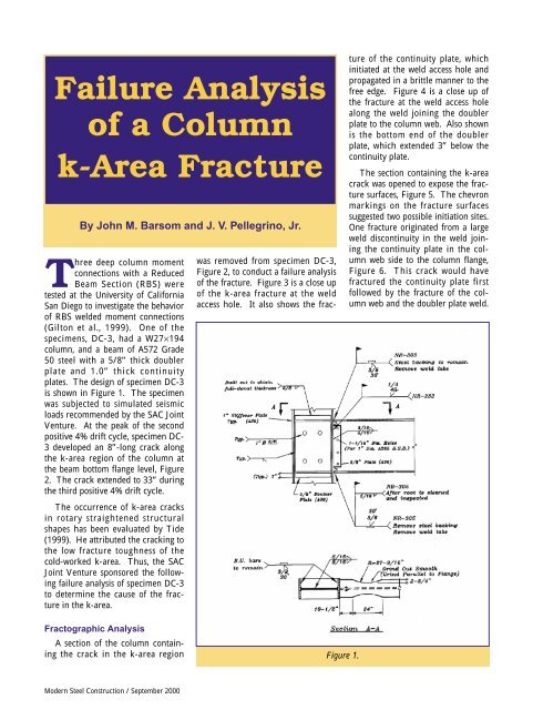
plates. The design <strong>of</strong> specimen DC-3<br />
is shown in Figure 1. The specimen<br />
was subjected to simulated seismic<br />
loads recommended by the SAC Joint<br />
Venture. At the peak <strong>of</strong> the second<br />
positive 4% drift cycle, specimen DC-<br />
3 developed an 8”-long crack along<br />
the k-area region <strong>of</strong> the column at<br />
the beam bottom flange level, Figure<br />
2. The crack extended to 33” during<br />
the third positive 4% drift cycle.<br />
The occurrence <strong>of</strong> k-area cracks<br />
in rotary straightened structural<br />
shapes has been evaluated by Tide<br />
(1999). He attributed the cracking to<br />
the low fracture toughness <strong>of</strong> the<br />
cold-worked k-area. Thus, the SAC<br />
Joint Venture sponsored the following<br />
failure analysis <strong>of</strong> specimen DC-3<br />
to determine the cause <strong>of</strong> the fracture<br />
in the k-area.<br />
Fractographic <strong>Analysis</strong><br />
A section <strong>of</strong> the column containing<br />
the crack in the k-area region<br />
<strong>Modern</strong> <strong>Steel</strong> Construction / September 2000<br />
was removed from specimen DC-3,<br />
Figure 2, to conduct a failure analysis<br />
<strong>of</strong> the fracture. Figure 3 is a close up<br />
<strong>of</strong> the k-area fracture at the weld<br />
access hole. It also shows the frac-<br />
Figure 1.<br />
ture <strong>of</strong> the continuity plate, which<br />
initiated at the weld access hole and<br />
propagated in a brittle manner to the<br />
free edge. Figure 4 is a close up <strong>of</strong><br />
the fracture at the weld access hole<br />
along the weld joining the doubler<br />
plate to the column web. Also shown<br />
is the bottom end <strong>of</strong> the doubler<br />
plate, which extended 3” below the<br />
continuity plate.<br />
The section containing the k-area<br />
crack was opened to expose the fracture<br />
surfaces, Figure 5. The chevron<br />
markings on the fracture surfaces<br />
suggested two possible initiation sites.<br />
One fracture originated from a large<br />
weld discontinuity in the weld joining<br />
the continuity plate in the column<br />
web side to the column flange,<br />
Figure 6. This crack would have<br />
fractured the continuity plate first<br />
followed by the fracture <strong>of</strong> the column<br />
web and the doubler plate weld.
The other fracture origin, Figure 7,<br />
was embedded within the column<br />
web in the vicinity <strong>of</strong> the fusion line<br />
between the doubler plate groove<br />
weld and the column web. This fracture<br />
would have severed the column<br />
web first followed by fracture <strong>of</strong> the<br />
doubler plate groove weld then the<br />
fracture <strong>of</strong> the continuity plate.<br />
Examination <strong>of</strong> the recorded strains<br />
during loading and the deformation<br />
pattern on the cracked section that<br />
was removed from the connection<br />
indicated that the 8” k-area crack<br />
occurred first, followed by the continuity<br />
plate fracture during the following<br />
positive load cycle.<br />
Therefore, the primary fracture was<br />
embedded within the column web.<br />
Examination <strong>of</strong> the fracture surface<br />
under a light microscope and a<br />
scanning-electron microscope indicated<br />
the presence <strong>of</strong> 0.07 to 0.10”<br />
long planar inclusions (laminations)<br />
at the primary fracture origin, Figure<br />
8, and at other locations away from<br />
the fracture origin. The sample<br />
shown in Figure 8 was tilted at a<br />
small angle to expose the laminations.<br />
The planes <strong>of</strong> these laminations<br />
were parallel to the web surfaces<br />
and perpendicular to the<br />
fracture plane. Therefore, these<br />
planes <strong>of</strong> discontinuities were parallel<br />
to the direction <strong>of</strong> stresses and<br />
strains that caused the fracture.<br />
Consequently, their contribution to<br />
the fracture process would have been<br />
negligible (Barsom and Rolfe, 1999).<br />
Scanning-electron fractography <strong>of</strong><br />
the fracture origin showed that the<br />
material between the two laminations<br />
at the fracture origin fractured by<br />
ductile shear then the fracture<br />
extended in a brittle cleavage mode,<br />
Figure 9. Also shown are a multitude<br />
<strong>of</strong> voids on the surface <strong>of</strong> the lamination<br />
where inclusions resided.<br />
Metallographic examination <strong>of</strong> a<br />
transverse cross section through the<br />
fracture origin revealed the presence<br />
<strong>of</strong> laminations immediately below the<br />
fracture origin, Figure 10. These<br />
laminations contained inclusions,<br />
Figure 11, which were identified by<br />
energy-dispersive x-ray spectroscopy<br />
to be manganese silicates, Figure 12.<br />
Figures 10 and 11 show that the<br />
ends <strong>of</strong> the laminations had extended<br />
a short distance out <strong>of</strong> plane to align<br />
themselves perpendicular to the<br />
direction <strong>of</strong> the applied stresses and<br />
strains. A high magnification scanning-electron<br />
fractograph, Figure 13,<br />
shows this extension was by formation<br />
and coalescence <strong>of</strong> ductile<br />
microvoids around inclusions and<br />
along grain boundaries. This observation<br />
demonstrates that, in the<br />
vicinity <strong>of</strong> the fracture, the steel was<br />
subjected to stress levels that<br />
approached the tensile strength<br />
prior to fracture.<br />
<strong>Fracture</strong> <strong>Analysis</strong><br />
The web fracture was a single<br />
event that initiated subsurface and<br />
propagated in a brittle manner about<br />
8” along the k-area region. Linear<br />
elastic fracture mechanics was used<br />
to establish the minimum size <strong>of</strong> an<br />
embedded crack-like imperfection<br />
that should have resided at the fracture<br />
origin had the fracture been<br />
defect governed. The relationship<br />
between fracture toughness, applied<br />
stress and the critical crack size for<br />
an embedded crack is:<br />
K<br />
IC<br />
a<br />
= σ<br />
Q<br />
π<br />
where K IC = critical stress-intensity<br />
factor; σ = applied stress; a c = critical<br />
crack size; and Q = factor related to<br />
the crack shape.<br />
The lowest fracture toughness,<br />
K IC , for any steel under the most<br />
severe conditions is equal to about<br />
25 ksi in. -½ . The maximum applied<br />
stress was assumed to be equal to the<br />
tensile strength <strong>of</strong> the steel in the karea,<br />
which was 85 ksi. Q is 2.4 for a<br />
circular penny-shaped crack and<br />
decreases to 1.0, as the crack<br />
becomes elliptical with a minor axis<br />
equal to 2a c and the major axis infinite<br />
in length. Equation 1 predicts<br />
the smallest crack size when Q = 1.0.<br />
c<br />
(1)<br />
Figure 2.<br />
Figure 3.<br />
Figure 4.<br />
Figure 5.<br />
Figure 6.<br />
<strong>Modern</strong> <strong>Steel</strong> Construction / September 2000
Figure 7.<br />
Figure 8.<br />
Figure 9.<br />
Figure 10.<br />
Figure 11.<br />
<strong>Modern</strong> <strong>Steel</strong> Construction / September 2000<br />
Substituting K IC = 25ksi in. -½ , σ = 85<br />
ksi and Q = 1 in Eq. 1 indicates that<br />
the smallest crack size, 2a c , that<br />
should reside at the fracture origin is<br />
0.056”. The plane <strong>of</strong> this crack must<br />
be parallel to and on the fracture<br />
surface. The planes <strong>of</strong> the laminations<br />
were perpendicular to the fracture<br />
surface. Examination <strong>of</strong> the<br />
fracture origin did not reveal the<br />
presence <strong>of</strong> a crack-like discontinuity<br />
<strong>of</strong> any size whose plane was along<br />
the fracture surface. Therefore, the<br />
fracture was not defect governed.<br />
Also, in the absence <strong>of</strong> a crack-like<br />
imperfection at the fracture origin,<br />
the fracture is not governed by the<br />
fracture toughness <strong>of</strong> the material.<br />
The fracture exhibited all the characteristics<br />
<strong>of</strong> a tensile fracture at<br />
stresses equal to the ultimate<br />
strength <strong>of</strong> the steel under constraint<br />
conditions.<br />
<strong>Fracture</strong> Mechanism<br />
Gilton et al. described the behavior<br />
<strong>of</strong> specimen DC-3 under simulated<br />
seismic loads (Gilton et al., 1999).<br />
During the 4% drift cycle, an 8” long<br />
crack developed suddenly along the<br />
k-area <strong>of</strong> the column at the beam<br />
bottom flange level. Prior to fracture,<br />
the specimen exhibited significant<br />
plastic deformation <strong>of</strong> the beam<br />
flanges, beam web, column web and<br />
continuity plates. Also, the column<br />
was subjected to large out-<strong>of</strong>-plane<br />
deformation reaching 5/8” during<br />
the 4% drift cycle. <strong>Analysis</strong> <strong>of</strong> the<br />
measured strains and deformation<br />
under load indicated that specimen<br />
DC-3 was subjected to a high<br />
demand/capacity ratio at the fracture<br />
location.<br />
The present failure analysis examined<br />
the yielding patterns on the<br />
beam flange, column flange, the<br />
panel zone and the continuity plates<br />
to identify the stresses, strains and<br />
deformations that caused the fracture.<br />
Prior to fracture, significant<br />
yielding <strong>of</strong> the beam flanges and<br />
web, the column web and continuity<br />
plate on the side <strong>of</strong> the panel zone<br />
without a doubler plate occurred at<br />
3% drift, Figure 14 (Gilton et al.,<br />
1999). However, negligible yielding<br />
had occurred in the doubler plate or<br />
in the continuity plate attached to it.<br />
At the instant <strong>of</strong> fracture the bottom<br />
continuity plate on the panel<br />
zone side without a doubler plate<br />
had yielded completely, Figure 3.<br />
The bottom continuity plate on the<br />
doubler plate side also yielded but to<br />
a lesser extent, Figure 4.<br />
Extensive yielding was observed<br />
on the column flange both above and<br />
below the bottom beam flange but<br />
only on the doubler plate side <strong>of</strong> the<br />
panel zone, Figure 5. The size <strong>of</strong> the<br />
plastically deformed area was larger<br />
below than above the bottom flange.<br />
Also, yielding extended more along<br />
the edge <strong>of</strong> the column flange than<br />
along the column flange-to-web<br />
intersection, Figure 5. Negligible<br />
yielding <strong>of</strong> the column flange on the<br />
panel zone side without a doubler<br />
plate had developed at the time <strong>of</strong><br />
the fracture, Figure 5.<br />
The plastic deformation pattern <strong>of</strong><br />
the column flange, Figure 5, both<br />
above and below the beam bottom<br />
flange and on both sides <strong>of</strong> the panel<br />
zone was consistent with out-<strong>of</strong>-plane<br />
bending <strong>of</strong> the column flange welded<br />
to the beam bottom flange. The larger<br />
magnitude <strong>of</strong> plastic deformation<br />
below the beam bottom flange represents<br />
the superposition <strong>of</strong> out-<strong>of</strong>plane<br />
bending <strong>of</strong> the column flange<br />
and the bending <strong>of</strong> the beam.<br />
The out-<strong>of</strong>-plane displacements<br />
and accompanying plastic deformation<br />
were largest at the free edge <strong>of</strong><br />
the column flange and decreased<br />
towards the column flange midthickness.<br />
Thus, the outside free<br />
edge <strong>of</strong> the continuity plate increased<br />
much more than the edge that was<br />
welded to the doubler plate. The<br />
doubler plate exhibited minor plastic<br />
yielding. Therefore, the doubler<br />
plate and the column web did not<br />
increase in length beyond the elastic<br />
range. The differential displacements<br />
induced severe stress in the<br />
column web, the doubler plate and
Figure 13.<br />
Figure 14a.<br />
Figure 14b.<br />
Figure 12.<br />
the weld joining them. As the out-<strong>of</strong>plane<br />
displacements and the beam<br />
deflection increased, the stress<br />
reached the tensile strength <strong>of</strong> the<br />
column web causing its fracture.<br />
The fracture propagated 8” along the<br />
k-area to the edge <strong>of</strong> the deformed<br />
region that was driving the crack,<br />
Figure 5. The next positive excursion<br />
extended the preexisting crack<br />
to 33” (Gilton et al., 1999).<br />
Summary<br />
The results <strong>of</strong> a failure analysis <strong>of</strong><br />
a column k-area fracture may be<br />
summarized as follows:<br />
✦ The k-line area origin was embedded<br />
within the web <strong>of</strong> the column;<br />
✦ The fracture was not caused by<br />
pre-existing defects;<br />
✦ The fracture was not influenced<br />
by the fracture toughness <strong>of</strong> the karea<br />
region; and<br />
✦ The fracture occurred when the<br />
applied stress level in the k-area<br />
region reached the tensile<br />
strength <strong>of</strong> the steel.<br />
References<br />
Barsom, J. M. and S. T. Rolfe. (1999)<br />
<strong>Fracture</strong> and Fatigue Control in<br />
Structures–Applications <strong>of</strong> <strong>Fracture</strong><br />
Mechanics, 3rd ed., ASTM MNL41,<br />
American Society for Testing and<br />
Materials, West Conshohocken, PA.<br />
Gilton, C. S., Brandon Chi and Chia-<br />
Ming Uang. (1999) “Brief Summary<br />
Report <strong>of</strong> Deep <strong>Column</strong> RBS<br />
Specimen DC-3”, University <strong>of</strong><br />
California, San Diego, SAC <strong>Steel</strong><br />
Project, SAC Joint Venture,<br />
Richmond, CA.<br />
Tide, R. H. R. (1999) “Evaluation <strong>of</strong><br />
steel properties and cracking in the<br />
“k”-area <strong>of</strong> W shapes.” Engineering<br />
Structures, 22 (2000), pp. 128-134,<br />
Elsevier Science Ltd., London, UK.<br />
John M. Barsom is a consultant with<br />
Barsom Consulting Ltd., Pittsburgh,<br />
PA. J. V. Pellegrino, Jr., is with<br />
WHEMCO, Homestead, PA.<br />
<strong>Modern</strong> <strong>Steel</strong> Construction / September 2000