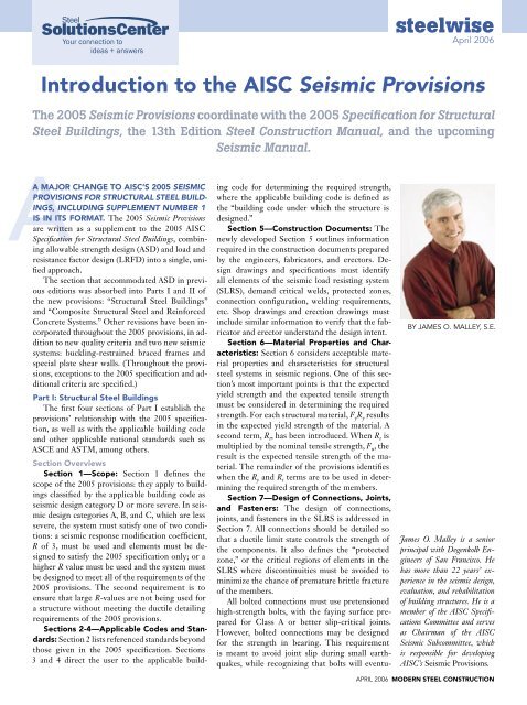
Introduction to the AISC Seismic Provisions steelwise - Modern Steel ...
Introduction to the AISC Seismic Provisions steelwise - Modern Steel ...
Introduction to the AISC Seismic Provisions steelwise - Modern Steel ...

Create successful ePaper yourself
Turn your PDF publications into a flip-book with our unique Google optimized e-Paper software.
Your connection <strong>to</strong><br />
ideas + answers<br />
A MAJOR CHANGE TO <strong>AISC</strong>’S 2005 SEISMIC<br />
PROVISIONS FOR STRUCTURAL STEEL BUILD-<br />
INGS, INCLUDING SUPPLEMENT NUMBER 1<br />
IS IN ITS FORMAT. The 2005 <strong>Seismic</strong> <strong>Provisions</strong><br />
are written as a supplement <strong>to</strong> <strong>the</strong> 2005 <strong>AISC</strong><br />
Specification for Structural <strong>Steel</strong> Buildings, combining<br />
allowable strength design (ASD) and load and<br />
resistance fac<strong>to</strong>r design (LRFD) in<strong>to</strong> a single, unified<br />
approach.<br />
The section that accommodated ASD in previous<br />
editions was absorbed in<strong>to</strong> Parts I and II of<br />
<strong>the</strong> new provisions: “Structural <strong>Steel</strong> Buildings”<br />
and “Composite Structural <strong>Steel</strong> and Reinforced<br />
Concrete Systems.” O<strong>the</strong>r revisions have been incorporated<br />
throughout <strong>the</strong> 2005 provisions, in addition<br />
<strong>to</strong> new quality criteria and two new seismic<br />
systems: buckling-restrained braced frames and<br />
special plate shear walls. (Throughout <strong>the</strong> provisions,<br />
exceptions <strong>to</strong> <strong>the</strong> 2005 specification and additional<br />
criteria are specified.)<br />
Part I: Structural <strong>Steel</strong> Buildings<br />
The first four sections of Part I establish <strong>the</strong><br />
provisions’ relationship with <strong>the</strong> 2005 specification,<br />
as well as with <strong>the</strong> applicable building code<br />
and o<strong>the</strong>r applicable national standards such as<br />
ASCE and ASTM, among o<strong>the</strong>rs.<br />
Section Overviews<br />
Section 1—Scope: Section 1 defines <strong>the</strong><br />
scope of <strong>the</strong> 2005 provisions: <strong>the</strong>y apply <strong>to</strong> buildings<br />
classified by <strong>the</strong> applicable building code as<br />
seismic design category D or more severe. In seismic<br />
design categories A, B, and C, which are less<br />
severe, <strong>the</strong> system must satisfy one of two conditions:<br />
a seismic response modification coefficient,<br />
R of 3, must be used and elements must be designed<br />
<strong>to</strong> satisfy <strong>the</strong> 2005 specification only; or a<br />
higher R value must be used and <strong>the</strong> system must<br />
be designed <strong>to</strong> meet all of <strong>the</strong> requirements of <strong>the</strong><br />
2005 provisions. The second requirement is <strong>to</strong><br />
ensure that large R-values are not being used for<br />
a structure without meeting <strong>the</strong> ductile detailing<br />
requirements of <strong>the</strong> 2005 provisions.<br />
Sections 2-4—Applicable Codes and Standards:<br />
Section 2 lists referenced standards beyond<br />
those given in <strong>the</strong> 2005 specification. Sections<br />
3 and 4 direct <strong>the</strong> user <strong>to</strong> <strong>the</strong> applicable build-<br />
ing code for determining <strong>the</strong> required strength,<br />
where <strong>the</strong> applicable building code is defined as<br />
<strong>the</strong> “building code under which <strong>the</strong> structure is<br />
designed.”<br />
Section 5—Construction Documents: The<br />
newly developed Section 5 outlines information<br />
required in <strong>the</strong> construction documents prepared<br />
by <strong>the</strong> engineers, fabrica<strong>to</strong>rs, and erec<strong>to</strong>rs. Design<br />
drawings and specifications must identify<br />
all elements of <strong>the</strong> seismic load resisting system<br />
(SLRS), demand critical welds, protected zones,<br />
connection configuration, welding requirements,<br />
etc. Shop drawings and erection drawings must<br />
include similar information <strong>to</strong> verify that <strong>the</strong> fabrica<strong>to</strong>r<br />
and erec<strong>to</strong>r understand <strong>the</strong> design intent.<br />
Section 6—Material Properties and Characteristics:<br />
Section 6 considers acceptable material<br />
properties and characteristics for structural<br />
steel systems in seismic regions. One of this section’s<br />
most important points is that <strong>the</strong> expected<br />
yield strength and <strong>the</strong> expected tensile strength<br />
must be considered in determining <strong>the</strong> required<br />
strength. For each structural material, F y R y results<br />
in <strong>the</strong> expected yield strength of <strong>the</strong> material. A<br />
second term, R t , has been introduced. When R t is<br />
multiplied by <strong>the</strong> nominal tensile strength, F u , <strong>the</strong><br />
result is <strong>the</strong> expected tensile strength of <strong>the</strong> material.<br />
The remainder of <strong>the</strong> provisions identifies<br />
when <strong>the</strong> R y and R t terms are <strong>to</strong> be used in determining<br />
<strong>the</strong> required strength of <strong>the</strong> members.<br />
Section 7—Design of Connections, Joints,<br />
and Fasteners: The design of connections,<br />
joints, and fasteners in <strong>the</strong> SLRS is addressed in<br />
Section 7. All connections should be detailed so<br />
that a ductile limit state controls <strong>the</strong> strength of<br />
<strong>the</strong> components. It also defines <strong>the</strong> “protected<br />
zone,” or <strong>the</strong> critical regions of elements in <strong>the</strong><br />
SLRS where discontinuities must be avoided <strong>to</strong><br />
minimize <strong>the</strong> chance of premature brittle fracture<br />
of <strong>the</strong> members.<br />
All bolted connections must use pretensioned<br />
high-strength bolts, with <strong>the</strong> faying surface prepared<br />
for Class A or better slip-critical joints.<br />
However, bolted connections may be designed<br />
for <strong>the</strong> strength in bearing. This requirement<br />
is meant <strong>to</strong> avoid joint slip during small earthquakes,<br />
while recognizing that bolts will eventu-<br />
<strong>steelwise</strong><br />
April 2006<br />
<strong>Introduction</strong> <strong>to</strong> <strong>the</strong> <strong>AISC</strong> <strong>Seismic</strong> <strong>Provisions</strong><br />
The 2005 <strong>Seismic</strong> <strong>Provisions</strong> coordinate with <strong>the</strong> 2005 Specification for Structural<br />
<strong>Steel</strong> Buildings, <strong>the</strong> 13th Edition <strong>Steel</strong> Construction Manual, and <strong>the</strong> upcoming<br />
<strong>Seismic</strong> Manual.<br />
BY JAMES O. MALLEY, S.E.<br />
James O. Malley is a senior<br />
principal with Degenkolb Engineers<br />
of San Francisco. He<br />
has more than 22 years’ experience<br />
in <strong>the</strong> seismic design,<br />
evaluation, and rehabilitation<br />
of building structures. He is a<br />
member of <strong>the</strong> <strong>AISC</strong> Specifications<br />
Committee and serves<br />
as Chairman of <strong>the</strong> <strong>AISC</strong><br />
<strong>Seismic</strong> Subcommittee, which<br />
is responsible for developing<br />
<strong>AISC</strong>’s <strong>Seismic</strong> <strong>Provisions</strong>.<br />
APRIL 2006 MODERN STEEL CONSTRUCTION
ally develop bearing during a design-level<br />
seismic event. Standard holes are required<br />
at bolted joints; short-slotted holes are acceptable<br />
when <strong>the</strong> axis is perpendicular <strong>to</strong><br />
<strong>the</strong> direction of load. Oversized holes also<br />
may be used if <strong>the</strong>y are in only one ply<br />
of <strong>the</strong> slip-critical joint. Bolts and welds<br />
are not allowed <strong>to</strong> share load at <strong>the</strong> same<br />
joint.<br />
Welded connections must be made<br />
with filler metals that have a minimum<br />
CVN <strong>to</strong>ughness of 20 ft-lbs at 0 ºF. This<br />
is a relaxation from <strong>the</strong> previously adopted<br />
temperature of -20 ºF. Demand critical<br />
welds still require filler metal with a minimum<br />
CVN <strong>to</strong>ughness of 20 ft-lbs at -20 ºF.<br />
An additional requirement of 40 ft-lbs at<br />
70 ºF CVN <strong>to</strong>ughness is placed on demand<br />
critical complete-joint-penetration<br />
groove welds in various systems (for example:<br />
welds of beam flanges <strong>to</strong> columns,<br />
column splice joints, and welds of beam<br />
webs <strong>to</strong> column flanges). Specific detailing<br />
requirements for continuity plates are also<br />
provided in this section.<br />
Section 8—Local and Global Instabilities:<br />
Requirements for local and global<br />
instabilities, as well as o<strong>the</strong>r general member<br />
requirements, are considered in Section<br />
8. The limiting width-<strong>to</strong>-thickness<br />
ratios of flanges and webs for members in<br />
<strong>the</strong> SLRS are provided. These ratios are<br />
more restrictive than <strong>the</strong> compact section<br />
ratios given in <strong>the</strong> 2005 specification<br />
because of <strong>the</strong> expected inelastic demand<br />
during seismic behavior. The remaining<br />
portion of this section emphasizes column<br />
design. Splices for columns that are<br />
not part of <strong>the</strong> SLRS now have special<br />
design requirements since research indicates<br />
<strong>the</strong>se columns may have significant<br />
flexure and shear demand during a severe<br />
seismic event.<br />
Sections 9 through 17 provide design<br />
requirements for each of <strong>the</strong> codified<br />
structural steel building systems:<br />
Section 9—Special Moment Frames<br />
(SMFs): SMFs are considered highly ductile<br />
and <strong>the</strong>refore have <strong>the</strong> highest R fac<strong>to</strong>r<br />
of <strong>the</strong> steel buildings systems discussed<br />
here. The proposed use of a particular<br />
moment-resisting joint must have a demonstrated<br />
capability of accommodating an<br />
inters<strong>to</strong>ry drift of 0.04 radians. This is accomplished<br />
by one of <strong>the</strong> following:<br />
➜ Using a connection prequalified for use<br />
in a SMF in accordance with Prequalified<br />
Connections for Special and Intermediate<br />
Moment Frames for <strong>Seismic</strong> Applications,<br />
(ANSI/<strong>AISC</strong> 358-05), a new<br />
MODERN STEEL CONSTRUCTION APRIL 2006<br />
standard developed by <strong>the</strong> <strong>AISC</strong> Connection<br />
Prequalification Review Panel<br />
(CPRP). In <strong>the</strong> first edition, approved<br />
in 2005, ANSI/<strong>AISC</strong> 358 included<br />
prequalification of <strong>the</strong> reduced beam<br />
section and end plate connections. Efforts<br />
continue <strong>to</strong> prequalify all widely<br />
used connections.<br />
➜ Using a connection prequalified for<br />
use in a SMF in accordance with Appendix<br />
P criteria, where minimum requirements<br />
for any moment-resisting<br />
joint are established. A CPRP will be<br />
established <strong>to</strong> review all test results<br />
and o<strong>the</strong>r data <strong>to</strong> ensure that <strong>the</strong> connection<br />
satisfies all minimum requirements.<br />
➜ Providing qualifying test results in<br />
accordance with Appendix S. This appendix<br />
requires <strong>the</strong> test assembly <strong>to</strong><br />
be consistent with joints proposed in<br />
<strong>the</strong> pro<strong>to</strong>type building, defines essential<br />
test parameters, and identifies <strong>the</strong><br />
test program implementation and <strong>the</strong><br />
adequacy of <strong>the</strong> joint <strong>to</strong> sustain <strong>the</strong><br />
required seismic demand. Test results<br />
can be taken from tests reported in <strong>the</strong><br />
literature or from tests performed specifically<br />
for <strong>the</strong> project under consideration.<br />
The panel zone must be consistent with<br />
<strong>the</strong> prequalified test configuration and <strong>the</strong><br />
expected strength must be approximately<br />
“balanced” with <strong>the</strong> yield strength of <strong>the</strong><br />
beams. In addition, all column splice<br />
strengths in bending and shear must be<br />
designed <strong>to</strong> develop <strong>the</strong> full flexural capacity<br />
of <strong>the</strong> smaller column spliced.<br />
Section 10—Intermediate Moment<br />
Frames (IMFs): Like SMFs, IMFs must<br />
have moment-resisting connections qualified<br />
in accordance with ANSI/<strong>AISC</strong> 358<br />
Appendix P or Appendix S. The qualifying<br />
inters<strong>to</strong>ry drift limit is reduced <strong>to</strong> 0.02<br />
radians for <strong>the</strong>se connections <strong>to</strong> reflect<br />
<strong>the</strong> more limited ductility demand expected<br />
from <strong>the</strong>se systems. Current building<br />
codes limit <strong>the</strong> use of IMFs in high<br />
seismic design categories. O<strong>the</strong>r than <strong>the</strong><br />
prequalified connection and <strong>the</strong> more restrictive<br />
lateral bracing requirements, <strong>the</strong><br />
2005 specification governs <strong>the</strong> design requirements<br />
of <strong>the</strong>se frames.<br />
Section 11—Ordinary Moment<br />
Frames (OMFs): OMFs are accepted in<br />
light metal buildings and small building<br />
applications in <strong>the</strong> more severe seismic<br />
design categories. OMFs may be designed<br />
without <strong>the</strong> prequalified performance<br />
testing requirement. In an effort <strong>to</strong> induce<br />
inelastic behavior in<strong>to</strong> <strong>the</strong> adjoining elements,<br />
<strong>the</strong> connection strength must exceed<br />
1.1 times <strong>the</strong> expected strength of<br />
<strong>the</strong> connected members. Specific requirements<br />
such as continuity plates, removing<br />
weld backing and run-off tabs, and weld<br />
access holes help ensure minimum ductile<br />
performance of OMF connections.<br />
Section 12—Special Truss Moment<br />
Frames (STMFs): STMF provisions define<br />
a special segment of <strong>the</strong> truss that is<br />
intended <strong>to</strong> be <strong>the</strong> primary location of<br />
inelastic behavior in <strong>the</strong> system. All o<strong>the</strong>r<br />
frame elements are designed with sufficient<br />
over-strength <strong>to</strong> develop yielding in<br />
<strong>the</strong> special segment. Both vierendeel and<br />
cross-braced special segment panels are<br />
allowed. The requirements also provide<br />
lateral bracing requirements similar <strong>to</strong><br />
those required for SMF systems <strong>to</strong> prohibit<br />
out-of-plane instability.<br />
Section 13—Special Concentrically<br />
Braced Frames (SCBFs): The concept<br />
for SCBF systems is that diagonal braces<br />
buckle and dissipate energy resulting from<br />
<strong>the</strong> design earthquake. The 2005 provisions<br />
have been modified <strong>to</strong> improve <strong>the</strong><br />
ductility of <strong>the</strong> system. For example, brace<br />
orientation in each line of framing must<br />
have approximately <strong>the</strong> same number of<br />
braces in compression and tension. Connections<br />
in SCBFs must develop <strong>the</strong> full<br />
tensile capacity of <strong>the</strong> brace or <strong>the</strong> maximum<br />
force that can be delivered <strong>to</strong> <strong>the</strong><br />
brace by <strong>the</strong> rest of <strong>the</strong> system. Full flexural<br />
strength must also be considered unless<br />
<strong>the</strong> connection includes a yield-line gusset<br />
plate that allows ductile post-buckled<br />
behavior of <strong>the</strong> brace. Special limitations<br />
are provided for V and inverted-V bracing<br />
<strong>to</strong> reflect <strong>the</strong> potentially undesirable characteristics<br />
of <strong>the</strong>se bracing configurations.<br />
Column splices in SCBFs are required <strong>to</strong><br />
develop a shear capacity of approximately<br />
50% of <strong>the</strong> member capacity <strong>to</strong> reflect <strong>the</strong><br />
substantial demands on <strong>the</strong>se elements<br />
during <strong>the</strong> earthquake.<br />
Section 14—Ordinary Concentrically<br />
Braced Frames (OCBF): Like<br />
OMFs, OCBFs have highly restricted applications<br />
in high seismic design categories<br />
due <strong>to</strong> <strong>the</strong>ir limited expected ductility.<br />
Connections in OCBFs may be designed<br />
<strong>to</strong> consider <strong>the</strong> amplified seismic load.<br />
The previous requirement of member design<br />
in OCBFs for <strong>the</strong> amplified seismic<br />
load was removed <strong>to</strong> address <strong>the</strong> reduced<br />
R fac<strong>to</strong>r given in ASCE 7-05, Minimum<br />
Design Loads for Buildings and O<strong>the</strong>r Structures.<br />
Like OMFs, OCBF applications are
also limited in high seismic design categories<br />
by <strong>the</strong> building codes.<br />
Section 15—Eccentrically Braced<br />
Frames (EBFs): The provisions for EBF<br />
design state that full yield must be induced<br />
and strain hardened within <strong>the</strong> eccentric link<br />
while <strong>the</strong> diagonal braces, columns, and beams<br />
outside <strong>the</strong> link beams remain essentially<br />
elastic. Because of its importance in system<br />
performance, proper design of <strong>the</strong> link beam<br />
is <strong>the</strong> primary focus of this section. Labora<strong>to</strong>ry<br />
testing has demonstrated that properly<br />
designed shear yielding links can undergo a<br />
link rotation angle of 0.08 radians. Moment<br />
yielding links are designed <strong>to</strong> undergo a link<br />
rotation angle of 0.02 radians, which is consistent<br />
with SMF systems. Interpolation is<br />
allowed for links with a length that results<br />
in a combination of shear and flexural yielding.<br />
Because of <strong>the</strong> high local deformation<br />
demands, link-<strong>to</strong>-column connections must<br />
be demonstrated by testing similar <strong>to</strong> SMF<br />
connections, in accordance with Appendices<br />
S and P or ANSI/<strong>AISC</strong> 358. An exception is<br />
provided if <strong>the</strong>re is substantial reinforcement<br />
of <strong>the</strong> connection that would preclude inelastic<br />
behavior in <strong>the</strong> connection welds.<br />
Section 16—Buckling-Restrained<br />
Braced Frames (BRBFs): Originally developed<br />
in Japan, <strong>the</strong> BRBF system has been used<br />
on a number of recent projects on <strong>the</strong> West<br />
Coast. This system relies on sustained compression<br />
due <strong>to</strong> local buckling of <strong>the</strong> brace<br />
while overall member buckling is restrained.<br />
This significantly increases <strong>the</strong> energy dissipation<br />
characteristics compared <strong>to</strong> <strong>the</strong> braces<br />
in a traditional SCBF system; <strong>the</strong>refore,<br />
BRBFs do not have <strong>the</strong> in-line brace configuration<br />
or o<strong>the</strong>r restrictions that are imposed<br />
on SCBFs. Similar <strong>to</strong> o<strong>the</strong>r structural system<br />
types, braces in a BRBF require prequalification<br />
testing as specified by Appendix T. The<br />
remaining design provisions are intended <strong>to</strong><br />
ensure that <strong>the</strong> connections and o<strong>the</strong>r members<br />
in <strong>the</strong> BRBF system remain essentially<br />
elastic at full capacity of <strong>the</strong> brace.<br />
Section 17—Special Plate Shear Walls<br />
(SPSWs): Although used on a number of<br />
buildings in high seismic regions as early as<br />
<strong>the</strong> 1970s, renewed interest in SPSW systems<br />
was generated in <strong>the</strong> early 1990s as a result of<br />
a series of research projects at two Canadian<br />
universities. Figure 1 shows typical inelastic<br />
behavior that might be expected from a<br />
SPSW. From this Canadian research, as well<br />
as ongoing research in <strong>the</strong> United States, design<br />
requirements for <strong>the</strong> system have been<br />
developed for this edition of <strong>the</strong> <strong>Seismic</strong><br />
<strong>Provisions</strong>. Favorable seismic performance is<br />
achieved by controlling stable post-buckled<br />
plate shear wall. Similar <strong>to</strong> plate girder behavior, tension field action develops as <strong>the</strong><br />
relatively thin web buckles during lateral loading. Limitations on configuration, widththickness<br />
ratios and o<strong>the</strong>r design parameters are provided <strong>to</strong> be consistent with <strong>the</strong> successful<br />
test results.<br />
4000<br />
3000<br />
2000<br />
1000<br />
Panel<br />
Shear 0<br />
(kN)<br />
-1000<br />
Part II contains individual sections governing design requirements for beams compos<br />
-2000<br />
Test<br />
concrete slabs, composite Strip Model:<br />
-3000 columns and <strong>the</strong> design of connections between concrete a<br />
Strip A Model: bl Frame<br />
-4000<br />
O l<br />
elements. Composite connections have been designed using <strong>the</strong> basic principles of me<br />
-60 -40 -20 0 20 40 60 80<br />
existing standards for steel and concrete construction, Panel Deformationtest<br />
data, and engineering judgme<br />
( )<br />
connection section is intended <strong>to</strong> standardize and improve design practice by establishin<br />
behavioral assumptions for developing design models that satisfying equilibrium of<br />
forces in <strong>the</strong> connection for seismic design.<br />
Figure 1. Special Plate Shear Figure Wall 1 – Special test results. Plate Shear Wall test results<br />
(Driver, (Driver, R.G., R.G., Kulak, Kulak, G.L., G.L., Kennedy, D.J.L., and Elwi, A.E., “<strong>Seismic</strong> Behavior Behavior of <strong>Steel</strong> of Plate<br />
<strong>Steel</strong> Plate Shear Walls,” Shear Walls,” Structural Structural Engineering Engineering Report No. 215, Report Department No. 215, of Department<br />
Civil Engineering,<br />
of Civil Engineering, University University of Alberta, of Alberta, Edmon<strong>to</strong>n, Edmon<strong>to</strong>n, Alberta, Alberta, Canada, 1997) Canada, 1997)<br />
The final section of Part I (Section 18) addresses a comprehensive quality assurance plan that is<br />
required <strong>to</strong> demonstrate that <strong>the</strong> structural design intent is accomplished during construction.<br />
Newly developed Appendix Q discusses requirements related <strong>to</strong> quality control <strong>to</strong> be provided<br />
by <strong>the</strong> contrac<strong>to</strong>r, and quality assurances. Inspection requirements, both visual and nondestructive<br />
evaluation (NDE) inspections, for welds are presented in tabular form. A similar<br />
table for bolted connections is also provided.<br />
PART II – COMPOSITE STRUCTURAL STEEL AND REINFORCED CONCRETE<br />
BUILDINGS<br />
Part II of <strong>the</strong> <strong>Seismic</strong> <strong>Provisions</strong> considers <strong>the</strong> design of composite systems of structural steel<br />
and reinforced concrete. Since composite systems are assemblies of structural steel elements<br />
with concrete components, cross-references with ACI 318 is an important feature in <strong>the</strong> 2005<br />
<strong>Provisions</strong>.<br />
Figure 2 – Example of a partially restrained composite connection.<br />
The remaining sections of Part II address <strong>the</strong> design of various composite structural<br />
types. These sections parallel those found in Part I, and generally have R fac<strong>to</strong>rs and<br />
application limitations similar <strong>to</strong> <strong>the</strong> comparable structural steel systems. In additio<br />
composite SMF, IMF and OMF system requirements, <strong>the</strong>re is a composite partially re<br />
moment frame (C-PRMF) system having connection details similar <strong>to</strong> that shown in F<br />
Similar <strong>to</strong> Part I, <strong>the</strong>re are two concentrically braced composite systems and one ecce<br />
braced composite system addressed. Part II also identifies three composite systems utiliz<br />
elements as <strong>the</strong> primary component in <strong>the</strong> SLRS. Two types of composite walls, one spe<br />
one ordinary, parallel <strong>the</strong> reinforced concrete wall specifications of ACI 318, except s<br />
steel elements are used in <strong>the</strong> boundary elements (as shown in Figure 3). Finally, a co<br />
steel plate shear wall system is also codified.<br />
Page 5<br />
Figure 2. Example of a partially restrained composite connection.<br />
Figure 3. Composite shear wall boundary element.<br />
Figure 3 – Composite shear wall boundary element.<br />
APRIL 2006 MODERN STEEL CONSTRUCTION<br />
In conclusion, over <strong>the</strong> last ten years, significant changes <strong>to</strong> <strong>the</strong> seismic design of stru
strength in <strong>the</strong> web of <strong>the</strong> steel plate shear<br />
wall.<br />
Similar <strong>to</strong> plate girder behavior, tension<br />
field action develops as <strong>the</strong> relatively thin<br />
web buckles during lateral loading. Limitations<br />
on configuration, width-thickness<br />
ratios, and o<strong>the</strong>r design parameters are<br />
provided <strong>to</strong> be consistent with <strong>the</strong> successful<br />
test results.<br />
Section 18—Quality Assurance:<br />
Section 18, <strong>the</strong> final section of Part I, addresses<br />
a comprehensive quality assurance<br />
plan that is required <strong>to</strong> demonstrate that<br />
<strong>the</strong> structural design intent is accomplished<br />
during construction. Newly developed<br />
Appendix Q discusses requirements<br />
related <strong>to</strong> quality assurances and quality<br />
control <strong>to</strong> be provided by <strong>the</strong> contrac<strong>to</strong>r.<br />
Inspection requirements, both visual and<br />
non-destructive evaluation (NDE) inspections,<br />
for welds are presented in tabular<br />
form. A similar table for bolted connections<br />
is also provided.<br />
Part II: Composite Structural <strong>Steel</strong><br />
and Reinforced Concrete Buildings<br />
Part II of <strong>the</strong> <strong>Seismic</strong> <strong>Provisions</strong> considers<br />
<strong>the</strong> design of composite systems of<br />
structural steel and reinforced concrete.<br />
This part contains individual sections<br />
MODERN STEEL CONSTRUCTION APRIL 2006<br />
governing design requirements for beams<br />
composite with concrete slabs, composite<br />
columns, and <strong>the</strong> design of connections<br />
between concrete and steel elements. (A<br />
cross-reference with ACI 318 is an important<br />
new feature.)<br />
Composite connections have been designed<br />
using <strong>the</strong> basic principles of mechanics,<br />
existing standards for steel and<br />
concrete construction, test data, and engineering<br />
judgment. The connection section<br />
is intended <strong>to</strong> standardize and improve<br />
design practices by establishing basic behavioral<br />
assumptions for developing design<br />
models that satisfy equilibrium of internal<br />
forces in <strong>the</strong> seismic design connection.<br />
The remaining sections of Part II address<br />
<strong>the</strong> design of various composite<br />
structural system types. These sections<br />
parallel those found in Part I and generally<br />
have R fac<strong>to</strong>rs and system application<br />
limitations similar <strong>to</strong> <strong>the</strong> comparable<br />
structural steel systems. In addition <strong>to</strong> <strong>the</strong><br />
composite SMF, IMF, and OMF system requirements,<br />
<strong>the</strong>re is a composite partially<br />
restrained moment frame (C-PRMF) system<br />
having connection details similar <strong>to</strong><br />
those shown in Figure 2.<br />
Similar <strong>to</strong> Part I, <strong>the</strong>re are two concen-<br />
trically braced composite systems and one<br />
eccentrically braced composite system addressed<br />
in Part II. Part II also identifies<br />
three composite systems that use wall elements<br />
as <strong>the</strong> primary component in <strong>the</strong><br />
SLRS. Two types of composite walls, one<br />
special and one ordinary, parallel <strong>the</strong> reinforced<br />
concrete wall specifications of ACI<br />
318; however, structural steel elements are<br />
used in <strong>the</strong> boundary elements (as shown<br />
in Figure 3). Finally, a composite steel<br />
plate shear wall system is also codified.<br />
More information may be found in <strong>the</strong><br />
paper “The 2005 <strong>AISC</strong> <strong>Seismic</strong> <strong>Provisions</strong><br />
for Structural <strong>Steel</strong> Buildings,” published in<br />
<strong>the</strong> 2005 North American <strong>Steel</strong> Construction<br />
Conference Proceedings, available<br />
for <strong>AISC</strong> members <strong>to</strong> download free at<br />
www.aisc.org.<br />
The 2005 <strong>Seismic</strong> <strong>Provisions</strong> for Structural<br />
<strong>Steel</strong> Buildings, Including Supplement<br />
Number 1 is available <strong>to</strong> download free<br />
from <strong>AISC</strong>’s web site at www.aisc.org.<br />
It is also available in print at www.aisc.<br />
org/books<strong>to</strong>re. This document has been<br />
adopted by reference in <strong>the</strong> 2006 International<br />
Building Code, and, as a result, will<br />
soon govern <strong>the</strong> seismic design of all steel<br />
buildings in <strong>the</strong> United States.