steelwise - Modern Steel Construction
steelwise - Modern Steel Construction
steelwise - Modern Steel Construction

Create successful ePaper yourself
Turn your PDF publications into a flip-book with our unique Google optimized e-Paper software.
<strong>steelwise</strong><br />
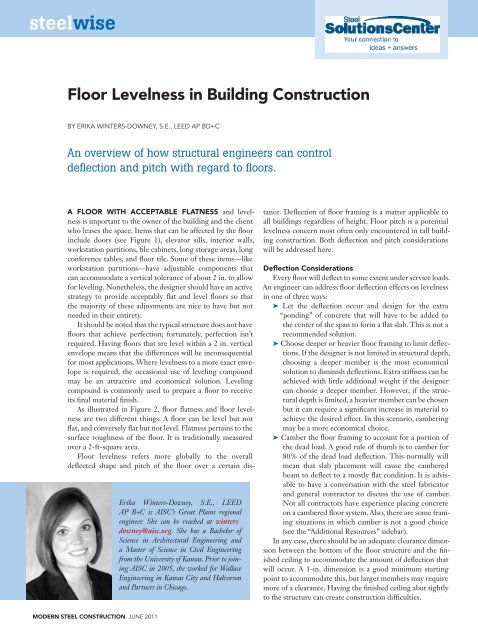
Floor Levelness in Building <strong>Construction</strong><br />
By erika Winters-DoWney, s.e., LeeD aP BD+C<br />
An overview of how structural engineers can control<br />
deflection and pitch with regard to floors.<br />
A FLOOR wITh ACCEpTABLE FLATNESS and levelness<br />
is important to the owner of the building and the client<br />
who leases the space. Items that can be affected by the floor<br />
include doors (see Figure 1), elevator sills, interior walls,<br />
workstation partitions, file cabinets, long storage areas, long<br />
conference tables, and floor tile. Some of these items—like<br />
workstation partitions—have adjustable components that<br />
can accommodate a vertical tolerance of about 2 in. to allow<br />
for leveling. Nonetheless, the designer should have an active<br />
strategy to provide acceptably flat and level floors so that<br />
the majority of these adjustments are nice to have but not<br />
needed in their entirety.<br />
It should be noted that the typical structure does not have<br />
floors that achieve perfection; fortunately, perfection isn’t<br />
required. Having floors that are level within a 2 in. vertical<br />
envelope means that the differences will be inconsequential<br />
for most applications. Where levelness to a more exact envelope<br />
is required, the occasional use of leveling compound<br />
may be an attractive and economical solution. Leveling<br />
compound is commonly used to prepare a floor to receive<br />
its final material finish.<br />
As illustrated in Figure 2, floor flatness and floor levelness<br />
are two different things. A floor can be level but not<br />
flat, and conversely flat but not level. Flatness pertains to the<br />
surface roughness of the floor. It is traditionally measured<br />
over a 2-ft-square area.<br />
Floor levelness refers more globally to the overall<br />
deflected shape and pitch of the floor over a certain dis-<br />
MODERN STEEL CONSTRUCTION june 2011<br />
Erika Winters-Downey, S.E., LEED<br />
AP B+C is AISC’s Great Plains regional<br />
engineer. She can be reached at winters<br />
downey@aisc.org. She has a Bachelor of<br />
Science in Architectural Engineering and<br />
a Master of Science in Civil Engineering<br />
from the University of Kansas. Prior to joining<br />
AISC in 2005, she worked for Wallace<br />
Engineering in Kansas City and Halvorson<br />
and Partners in Chicago.<br />
tance. Deflection of floor framing is a matter applicable to<br />
all buildings regardless of height. Floor pitch is a potential<br />
levelness concern most often only encountered in tall building<br />
construction. Both deflection and pitch considerations<br />
will be addressed here.<br />
Deflection Considerations<br />
Every floor will deflect to some extent under service loads.<br />
An engineer can address floor deflection effects on levelness<br />
in one of three ways:<br />
➤ Let the deflection occur and design for the extra<br />
“ponding” of concrete that will have to be added to<br />
the center of the span to form a flat slab. This is not a<br />
recommended solution.<br />
➤ Choose deeper or heavier floor framing to limit deflections.<br />
If the designer is not limited in structural depth,<br />
choosing a deeper member is the most economical<br />
solution to diminish deflections. Extra stiffness can be<br />
achieved with little additional weight if the designer<br />
can choose a deeper member. However, if the structural<br />
depth is limited, a heavier member can be chosen<br />
but it can require a significant increase in material to<br />
achieve the desired effect. In this scenario, cambering<br />
may be a more economical choice.<br />
➤ Camber the floor framing to account for a portion of<br />
the dead load. A good rule of thumb is to camber for<br />
80% of the dead load deflection. This normally will<br />
mean that slab placement will cause the cambered<br />
beam to deflect to a mostly flat condition. It is advisable<br />
to have a conversation with the steel fabricator<br />
and general contractor to discuss the use of camber.<br />
Not all contractors have experience placing concrete<br />
on a cambered floor system. Also, there are some framing<br />
situations in which camber is not a good choice<br />
(see the “Additional Resources” sidebar).<br />
In any case, there should be an adequate clearance dimension<br />
between the bottom of the floor structure and the finished<br />
ceiling to accommodate the amount of deflection that<br />
will occur. A 1-in. dimension is a good minimum starting<br />
point to accommodate this, but larger members may require<br />
more of a clearance. Having the finished ceiling abut tightly<br />
to the structure can create construction difficulties.
➤<br />
Fig. 1: Floor levelness can affect finishes like<br />
this office door.<br />
Floor pitch and Differential Shortening<br />
Floor pitch is the slope of a slab between<br />
two points, such as between the core and the<br />
perimeter of a building. It can be affected by<br />
many variables, including the type of structural<br />
system used. For example, a steel frame with<br />
a reinforced concrete core system has factors<br />
such as those illustrated in Figure 3. Concrete<br />
tolerances, core wall shortening, perimeter<br />
column shortening, foundation settlement,<br />
and steel fabrication and erection tolerances<br />
all can contribute to floor pitch.<br />
<strong>Steel</strong> shortens elastically under load by an<br />
amount that can be calculated with the equation<br />
Δ=PL/AE. Generally, this is not an issue in buildings<br />
with fewer than 20 stories. Although the<br />
engineer initially might be concerned about core<br />
wall shrinkage in a tall building with steel framing<br />
around a reinforced concrete core, perimeter<br />
column shortening will play a greater role in differential<br />
shortening of the perimeter relative to<br />
the core. The area of the column, A, in the equation<br />
gives a clue as to why. The combined crosssectional<br />
area of all of the steel columns is usually<br />
much smaller than the cross-sectional area of the<br />
concrete core walls. In addition, the core walls<br />
usually are stressed to a lower percentage of their<br />
vertical strength than the steel columns because<br />
the core wall is normally designed to act as part<br />
of the lateral system in addition to carrying gravity<br />
load. Therefore, the majority of the shortening<br />
in tall buildings will be in the steel columns.<br />
Floor pitch Strategies<br />
Because many variables contribute to floor<br />
pitch (as illustrated for one example building<br />
in Figure 3), it is helpful to decide which can<br />
be controlled and which can be accommodated<br />
through in-process adjustment. Understanding<br />
the means and methods the contractor will<br />
use to build the core and framing is important<br />
when selecting the right strategy to achieving<br />
a reasonably level floor. The recommended<br />
actions depend on the height of the building<br />
and the structural system. The recommendations<br />
below are for a building with a concrete<br />
core and steel perimeter framing.<br />
On buildings of 20 stories or less, an active<br />
strategy to compensate for core and perimeter<br />
shortening generally is not needed. In this case,<br />
the contractor typically will use the “tape-up”<br />
method to build the core—the concrete core is<br />
built based upon the design floor-to-floor height,<br />
➤<br />
➤<br />
Floor Levelness<br />
Fig. 2: Floor flatness vs. floor levelness. note: Floor levelness (FL) is not to be specified<br />
for elevated, unshored construction.<br />
Fig. 3: Variables affecting floor pitch.<br />
slab Placement<br />
and Finish<br />
Base Plate<br />
setting tolerance<br />
reference Floor<br />
elevation<br />
Magnitude of<br />
slope Changes<br />
Core Wall<br />
shortening<br />
Column<br />
shortening<br />
Photos and figures by Magnusson klemencic associates, inc.<br />
Floor Flatness = a 2 in. measure<br />
of surface<br />
actual<br />
Floor Line<br />
Foundation<br />
settlement<br />
roughness (F F)<br />
Mean Floor<br />
Line<br />
Fabrication/<br />
erection<br />
tolerance<br />
june 2011 MODERN STEEL CONSTRUCTION
measured from the previous floor. There<br />
does not need to be an active survey to level<br />
off columns or the core in most situations.<br />
For taller buildings, a more typical<br />
strategy is to build the core walls to the<br />
design elevations and lengthen the perimeter<br />
columns based upon the loadings and<br />
construction sequence. As the core is built,<br />
it will experience shrinkage. On higher<br />
floors, the core might require an extra frac-<br />
Table 1 – Recommended strategies for controlling floor pitch.<br />
Building height Recommended Action for Floor pitch<br />
1-20 stories no action necessary for floor pitch.<br />
20-30 stories<br />
30-40 stories<br />
40-60 stories<br />
60+ stories<br />
evaluate system, possibly no action needed; possible use of shims to<br />
periodically level out columns. Build core to design elevation.<br />
Build core to design elevation. Consider lengthening each tier—usually<br />
a two-story column—by 1 ⁄16 in. additional shims at column splices if<br />
necessary. actively survey and level off columns to design elevation using<br />
shim plates twice, at third points of height.<br />
Build core to design elevation. Consider lengthening each tier (two-story<br />
column) by 1 ⁄8 in. on lower floors and 1 ⁄16 in. on upper floors. actively<br />
survey and level off columns to design elevation using shim plates<br />
approximately every 15 floors.<br />
active strategy needed based upon detailed shrinkage analysis of core and<br />
perimeter using staged construction loading. over-lengthening of columns<br />
recommended. Build core to design elevation. actively survey and level off<br />
columns to design elevation using shim plates approximately every 15 floors.<br />
MODERN STEEL CONSTRUCTION june 2011<br />
tion of distance to be placed to the design<br />
elevation level. By building the core to<br />
the design elevation, this is a variable that<br />
can be controlled. Then, the elevations of<br />
the steel column splices can be adjusted<br />
periodically. One possible strategy is to<br />
have the columns fabricated slightly long<br />
to offset some of the shortening they will<br />
experience. This strategy allows—and<br />
often requires—adjustment of the fabri-<br />
cated length of columns in the next tier<br />
based upon the actual shortening in earlier<br />
sequences. This requires active coordination<br />
by the EOR, GC, fabricator and erector.<br />
Refer to Table 1 for recommendations<br />
for buildings of various heights.<br />
Attempting to accommodate long-term<br />
shrinkage of the core by building it high is<br />
not recommended because it might take up<br />
to three years for the core to fully shrink.<br />
This will result in significant floor pitch for<br />
several years until the core experiences its<br />
final shrinkage.<br />
Where floor levelness is a critical project<br />
consideration, it may be desirable to consider<br />
using a raised access floor. This can<br />
guide your decision on column over-lengths.<br />
If a building is to be built with a raised access<br />
floor, it may be best to err on the shorter side<br />
of adjusting column over-length. If there is a<br />
slight floor pitch to the outside, the ceiling<br />
below can normally accommodate it. This<br />
also ensures the maximum clearance below<br />
for any MEP runs at the core, which is where<br />
they need the most space. The raised floor<br />
can be adjusted slightly shorter at the elevators.<br />
If there is to be no raised access floor,<br />
it may be best to err on the side of having<br />
{
the perimeter columns longer so that any<br />
pitch occurs down to the center. This can be<br />
accommodated with leveling compound at<br />
the elevator sills.<br />
Team Coordination and Specification<br />
Language<br />
A floor levelness approach needs to be<br />
adopted by the design team prior to construction.<br />
Typical language might state that<br />
the maximum allowable pitch between the<br />
slab at the central core and the perimeter<br />
is 2 in. However, this leaves open the possibility<br />
that one side of the building might<br />
be 2 in. high and one side 2 in. low. It is<br />
important to be specific and state the criteria,<br />
possibly that the envelope from high<br />
point to low point on the floor should<br />
be no more than 2 in. The strategy to be<br />
used may impact the chosen envelope, and<br />
should be discussed prior to specification.<br />
Ideally, steel elevations during construction<br />
should be read early in the morning,<br />
before sunrise, to minimize the impact of<br />
temperature effects. Taking consistent surveys<br />
allows the erector to make mid-course<br />
adjustments as necessary. It is good to have<br />
column splice elevations sent to the GC and<br />
SEOR regularly to ensure that the necessary<br />
communication and coordination takes place.<br />
The main goal is communication. Put<br />
floor levelness on the list of topics to be<br />
discussed at a pre-construction planning<br />
meeting. Getting everyone from the design<br />
team to the construction workers on board<br />
with the strategy will help keep the project<br />
running smoothly.<br />
The author wishes to acknowledge significant<br />
contributions from David E. Eckmann,<br />
S.E., P.E., AIA, Ronald B. Johnson, S.E., and<br />
Michael Lederle, S.E., P.E.<br />
Additional Resources<br />
additional information related to floor<br />
construction can be found in the articles<br />
“specifying Camber” by erika<br />
Winters-Downey (MSC july 2006)<br />
and “tolerating tolerances” by kurt<br />
Gustafson (MSC june 2005). Both are<br />
available as free downloads at www.<br />
modernsteel.com/backissues.<br />
another good reference on the subject<br />
is aisC <strong>Steel</strong> Design Guide No. 3,<br />
Serviceability Design Considerations for<br />
<strong>Steel</strong> Buildings. all of the aisC design<br />
guides are available at www.aisc.org/<br />
dg as free downloads for aisC members<br />
and for purchase by others.<br />
june 2011 MODERN STEEL CONSTRUCTION