Value Engineering for Steel Construction - Modern Steel Construction
Value Engineering for Steel Construction - Modern Steel Construction
Value Engineering for Steel Construction - Modern Steel Construction

Create successful ePaper yourself
Turn your PDF publications into a flip-book with our unique Google optimized e-Paper software.
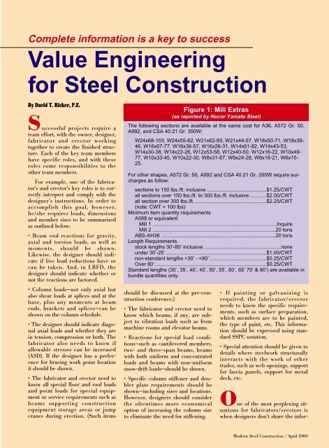
Complete in<strong>for</strong>mation is a key to success<br />
<strong>Value</strong> <strong>Engineering</strong><br />
<strong>for</strong> <strong>Steel</strong> <strong>Construction</strong><br />
By David T. Ricker, P.E.<br />
S uccessful projects require a<br />
team ef<strong>for</strong>t, with the owner, designer,<br />
fabricator and erector working<br />
together to create the finished structure.<br />
Each of the key team members<br />
have specific roles, and with these<br />
roles come responsibilities to the<br />
other team members.<br />
For example, one of the fabricator’s<br />
and erector’s key roles is to correctly<br />
interpret and comply with the<br />
designer’s instructions. In order to<br />
accomplish this goal, however,<br />
he/she requires loads, dimensions<br />
and member sizes to be summarized<br />
as outlined below:<br />
Beam end reactions <strong>for</strong> gravity,<br />
axial and torsion loads, as well as<br />
moments, should be shown.<br />
Likewise, the designer should indicate<br />
if live load reductions have or<br />
can be taken. And, in LRFD, the<br />
designer should indicate whether or<br />
not the reactions are factored.<br />
Column loads—not only axial but<br />
also shear loads at splices and at the<br />
base, plus any moments at beam<br />
ends, brackets and splices—can be<br />
shown on the column schedule.<br />
The designer should indicate diagonal<br />
axial loads and whether they are<br />
in tension, compression or both. The<br />
fabricator also needs to know if<br />
allowable stresses can be increased<br />
(ASD). If the designer has a preference<br />
<strong>for</strong> bracing work point location<br />
it should be shown.<br />
The fabricator and erector need to<br />
know all special floor and roof loads<br />
and point loads <strong>for</strong> special equipment<br />
or service requirements such as<br />
beams supporting construction<br />
equipment storage areas or jump<br />
cranes during erection. (Such items<br />
should be discussed at the pre-construction<br />
conference.)<br />
The fabricator and erector need to<br />
know which beams, if any, are subject<br />
to vibration loads such as from<br />
machine rooms and elevator beams.<br />
Reactions <strong>for</strong> special load conditions—such<br />
as cantilevered members,<br />
two- and three-span beams, beams<br />
with both uni<strong>for</strong>m and concentrated<br />
loads and beams with non-uni<strong>for</strong>m<br />
snow-drift loads—should be shown.<br />
Specific column stiffener and doubler<br />
plate requirements should be<br />
shown—including sizes and locations.<br />
However, designers should consider<br />
the oftentimes more economical<br />
option of increasing the column size<br />
to eliminate the need <strong>for</strong> stiffening.<br />
Figure 1: Mill Extras<br />
(as reported by Nucor Yamato <strong>Steel</strong>)<br />
The following sections are available at the same cost <strong>for</strong> A36, A572 Gr. 50,<br />
A992, and CSA 40.21 Gr. 350W:<br />
W24x68-103, W24x55-62, W21x62-93, W21x44-57, W18x50-71, W18x35-<br />
46, W16x67-77, W16x36-57, W16x26-31, W14x61-82, W14x43-53,<br />
W14x30-38, W14x22-26, W12x53-58, W12x40-50, W12x16-22, W10x49-<br />
77, W10x33-45, W10x22-30, W8x31-67, W8x24-28, W8x18-21, W6x15-<br />
25.<br />
For other shapes, A572 Gr. 50, A992 and CSA 40.21 Gr. 350W require surcharges<br />
as follow:<br />
sections to 150 lbs./ft. inclusive ..........................................$1.25/CWT<br />
all sections over 150 lbs./ft. to 300 lbs./ft. inclusive............$2.00/CWT<br />
all section over 300 lbs./ft. ..................................................$2.25/CWT<br />
(note: CWT = 100 lbs)<br />
Minimum item quantity requirements<br />
A588 or equivalent<br />
Mill 1 ......................................................................................Inquire<br />
Mill 2 ......................................................................................20 tons<br />
ABS-AH36 ................................................................................20 tons<br />
Length Requirements<br />
stock lengths 30’-80’ inclusive ......................................................none<br />
under 30’-25’ ......................................................................$1.00/CWT<br />
non-standard lengths >30’ -
Figure 3<br />
Figure 2<br />
mation developed during the design<br />
process. During the design process,<br />
the structural engineer develops all<br />
of the in<strong>for</strong>mation required to fabricate<br />
and connect the structural steel<br />
members, including loads, reactions,<br />
stiffening, special conditions, etc. But<br />
when it comes to the design drawing,<br />
the engineer all-to-often merely<br />
shows the member sizes.<br />
Skimping on the design drawing<br />
always comes back to haunt the<br />
designer in the <strong>for</strong>m of questions,<br />
higher bids, change orders, arbitrating<br />
disputes, a slower<br />
review/approval process and a dragging<br />
construction schedule. If it is a<br />
question of time, then the designer<br />
is fooling himself or herself. The<br />
time the fabricator spends deriving<br />
all of the needed in<strong>for</strong>mation is<br />
passed back to the owner in the <strong>for</strong>m<br />
of higher fees. And the engineer’s<br />
approval reviewer has to spend additional<br />
time analyzing the questions<br />
and change orders.<br />
The solution is greater teamwork<br />
and a consciousness of the importance<br />
of value engineering. The team<br />
member with the greatest impact on<br />
the economic success of the project is<br />
the designer. The team members all<br />
live or die with the engineer’s design.<br />
The following is a checklist of items<br />
designers should consider while<br />
designing a steel project.<br />
Capitalize on steel’s strengths.<br />
Good weight-to-strength ratio<br />
Efficiency of pre-assembly.<br />
Speed of delivery and erection.<br />
Strength in three directions.<br />
Ease of modification/renovation.<br />
A designer should keep current<br />
on the cost and availability of the<br />
various steel products he/she prescribes.<br />
A steel fabricator can supply<br />
basic steel prices and mill extras (see<br />
figure 1). A designer also should be<br />
aware of where the money is spent<br />
on steel construction: approximately<br />
30% on material, 30% on shop costs,<br />
30% on erection, and 10% of other<br />
items such as shop drawings, painting<br />
and shipping. Labor is more than<br />
60%!<br />
Consider using partial composite<br />
design of floor beams—something<br />
in the range of 50% - 75%. Full<br />
composite design is often inefficient<br />
and uneconomical. The cost of one<br />
shear stud in place equals the cost of<br />
approximately 10 lbs. of steel. Unless<br />
this ratio can be attained, the addition<br />
of more studs will prove uneconomical.<br />
Take advantage of live-load<br />
reductions if governing codes permit.<br />
Select optimum bay sizes. An<br />
exhaustive study by John Ruddy,<br />
P.E., of Structural Affiliates<br />
International in Nashville (AISC<br />
<strong>Engineering</strong> Journal, Vol 20, #3,<br />
1983) indicated that a rectangular<br />
bay with a length-to-width ratio of<br />
approximately 1.25 to 1.50 was the<br />
most efficient. The filler members<br />
should span in the long direction<br />
with the girder beams in the short<br />
direction (see figure 2).<br />
Tailor the surface preparation<br />
and the painting requirements to<br />
the project conditions—do not overdo<br />
or underdo the coating requirements.<br />
An extensive examination of a<br />
multitude of aged structures with<br />
steel frames indicates that the presence<br />
or absence of a shop primer is<br />
immaterial as long as the structural<br />
steel is kept dry (LRFD Specification<br />
Commentary Chapter M). These<br />
same studies indicate that shop<br />
primer alone af<strong>for</strong>ds very little protection<br />
if a structure develops a serious<br />
leak. In recent years, the trend<br />
has gone toward not painting. There<br />
are many side benefits to be gained<br />
by the omission of paint—no masking<br />
around bolt holes, better adhesion<br />
<strong>for</strong> concrete and/or fire proofing,<br />
easier weldability, ease of inspection,<br />
ease of making field repairs/alterations,<br />
etc. If shop painting is necessary,<br />
bear in mind that a shop coat is<br />
by definition a temporary coat—usually<br />
serving less than six months in<br />
duration. As such, there is little justification<br />
that the coat be perfect (that<br />
is, of uni<strong>for</strong>m thickness with no<br />
drips, runs or sags).<br />
Show all necessary loads on the<br />
design drawing to avoid costly overdesigning<br />
of connections or—worse<br />
yet—underdesigning. The designer<br />
who provides a complete design will<br />
find that the subsequent review and<br />
approval process of shop drawings<br />
will be much quicker and more<br />
ositive.
Make sure the general contractor<br />
or construction manager indicates<br />
who is responsible <strong>for</strong> any “grey<br />
areas” such as loose lintels, masonry<br />
anchors, elevator sill angles, elevator<br />
sheave beams, fastenings <strong>for</strong> precast<br />
concrete spandrel beams, etc. Unless<br />
the responsibility is specifically delegated,<br />
it is likely that the cost of<br />
these items will be included in the<br />
bids of multiple contractors, which<br />
means the owner will pay more than<br />
once <strong>for</strong> the same article.<br />
Don’t require the steel sub-contractor<br />
to per<strong>for</strong>m work normally<br />
done by other trades, such as<br />
installing masonry anchors, ceiling<br />
hangers, toilet partition supports,<br />
window wall supports, etc.<br />
In<strong>for</strong>mation required to per<strong>for</strong>m this<br />
work is often slow to develop, resulting<br />
in needless delay to the fabricator.<br />
The most efficient steel jobs are<br />
those on which the fabricator and<br />
erector are allowed to concentrate on<br />
the steel frame while unencumbered<br />
by the intricacies pertinent to other<br />
trades. This reduces coordination<br />
requirements and allows the steel<br />
framework to be turned over to the<br />
other trades in far less time than<br />
would otherwise be possible.<br />
Consider the use of cantilevered<br />
rafters and purlins to save weight<br />
on roof design (see figure 3).<br />
Do not design <strong>for</strong> minimum<br />
weight alone. The savings in material<br />
cost will often be negated by the<br />
need <strong>for</strong> more members, more connections<br />
and more costly shop work<br />
and field erection.<br />
Excessively stringent mill, fabrication<br />
and erection tolerances<br />
beyond state-of-the-art construction<br />
practices will reduce the<br />
number of bidders and raise the<br />
cost of the project. ASTM A6 tolerances<br />
and those established by AWS<br />
and AISC have served the industry<br />
well <strong>for</strong> many years and should be<br />
adhered to except under extraordinary<br />
circumstances where some special<br />
condition dictates a more strict<br />
treatment.<br />
Design the proper type of highstrength<br />
bolt value. The correct<br />
application of each type is well-documented<br />
in the current bolt specifications.<br />
Do not specify “slip-critical”<br />
bolt values <strong>for</strong> the purpose<br />
of obtaining an Figure 4<br />
extra factor of safety.<br />
The trend in recent<br />
years is toward the use<br />
of “snug-tight” bolts<br />
and bearing values.<br />
Allow the use of<br />
tension control<br />
(twist-off) highstrength<br />
bolts. These<br />
bolts are as reliable as<br />
other methods of measuring<br />
bolt tension and<br />
save labor costs in both<br />
shop and field.<br />
Where possible,<br />
specify fillet welds<br />
rather than groove<br />
welds. Groove welds<br />
are more costly<br />
because of the joint<br />
preparation required<br />
and the generally<br />
greater volume of weld<br />
(see figure 4).<br />
Use single-pass<br />
welds where possible.<br />
This involves keeping<br />
fillet welds to a maximum<br />
of 5/16”.<br />
Favor the horizontal<br />
and flat welding<br />
positions. These welds<br />
are easier and quicker<br />
to make and are generally<br />
of high quality<br />
(see figure 5).<br />
Don’t specify more weld than is<br />
necessary. Over-welding creates<br />
excessive heat, which may contribute<br />
to warping and shrinkage of the<br />
members resulting in costly straightening<br />
expense.<br />
Grant the fabricator the option<br />
of eliminating some column<br />
splices. The cost of one column<br />
splice equals the cost of approximately<br />
500 lbs. of A992 steel. The<br />
fabricator should study the situation<br />
carefully be<strong>for</strong>e he decides to omit<br />
the column splice as the resulting<br />
column may be too long <strong>for</strong> safe<br />
erection. Multi-tier columns should<br />
be designed to have splices every two<br />
or four floors. Three-floor columns<br />
are to be avoided due to erection difficulties.<br />
The higher up in a tall<br />
building, the less desirable it is to use<br />
Figure 5<br />
Figure 6<br />
four-floor columns due to higher<br />
wind speed and difficulties in guying.<br />
Avoid designing column splices<br />
at mid-story height. These are often<br />
too high <strong>for</strong> the erector to reach<br />
without rigging a float or scaffold. If<br />
the splice can be located no higher<br />
than 5’ above the tops of the steel<br />
beams, it saves the expense of the<br />
extra rigging and still will be in a<br />
region of the column where bending<br />
<strong>for</strong>ces are relatively low (see figure<br />
6).<br />
Except where dictated by seismic<br />
considerations, do not design column<br />
splices to “develop the full<br />
bending strength of the governing<br />
column size.” Seldom is the splice<br />
located at the point of maximum<br />
bending and seldom do the bending<br />
stresses result in a condition that
Figure 7<br />
wold require a full-strength splice.<br />
The column has axial compression<br />
stresses. The excess capacity is allotted<br />
to bending stress that occur as<br />
compression in one flange and tension<br />
in the other. The compression<br />
<strong>for</strong>ces are added to each other at one<br />
flange while at the other flange the<br />
tension <strong>for</strong>ce is subtracted from the<br />
compression <strong>for</strong>ce. Seldom does this<br />
other side of the column ever go into<br />
tension and never into full allowable<br />
tension of the magnitude that would<br />
require a full-strength splice. Thus,<br />
except in high seismic construction<br />
there is little justification <strong>for</strong> ever<br />
requiring a full-strength column<br />
splice (see figure 6).<br />
Consider using a heavier column<br />
shaft to eliminate the need <strong>for</strong><br />
web doubler plates and/or column<br />
stiffeners opposite the flanges of<br />
moment-connected beams. One<br />
pair of stiffeners installed costs<br />
approximately the same as 300 lbs. of<br />
A992 steel if the stiffeners are filletwelded.<br />
If they are groove welded,<br />
the cost skyrockets to the equivalent<br />
of 1000 lbs. of A992 steel. The cost<br />
of one installed doubler plate is<br />
about the same as 350 lbs. of A992<br />
steel (see figure 7). Considering that<br />
<strong>for</strong> an average two-floor column<br />
there could be as many as four pair<br />
of stiffeners and two or more doubler<br />
plates, at least 1900 lbs. of A992 steel<br />
could be sacrificed in order to save<br />
the time and expense of making the<br />
lighter shaft compliant. (For more<br />
in<strong>for</strong>mation, see AISC Design Guide<br />
#13: Wide-Flange Column Stiffening<br />
at Moment Connections. To order<br />
AISC publications and software, visit<br />
www.aisc.org or call 800/644-2400.)<br />
<strong>Modern</strong> <strong>Steel</strong> <strong>Construction</strong> / April 2000<br />
Figure 8<br />
Avoid designing heavy or awkward<br />
members in remote hard-toreach<br />
portions of the structure.<br />
This may eliminate the need <strong>for</strong> larger,<br />
more expensive hoisting equipment.<br />
Rein<strong>for</strong>ce beam-web penetrations<br />
only where necessary. It may<br />
be less costly to use a beam with a<br />
thicker web, to move the opening to<br />
a less critical location or to change<br />
the proportions of the opening to<br />
something less demanding (see figure<br />
8). To help in designing web openings,<br />
AISC published Design Guide<br />
#2: Design of <strong>Steel</strong> and Composite<br />
Beams with Web Openings. AISC<br />
also offers a software program,<br />
Webopen, to help in designing web<br />
openings. To order AISC publications<br />
and software, visit www.aisc.org or<br />
call 800/644-2400 to order publications<br />
and 312/670-5444 to order<br />
software.<br />
Allow the prudent use of oversized<br />
holes and slots to facilitate<br />
fit-up and erection. They may eliminate<br />
or reduce the need <strong>for</strong> costly<br />
reaming of holes or modification of<br />
connection parts in the field.<br />
For ordinary structures, do not<br />
specify that connection material<br />
be of one type to the exclusion of<br />
other types. Allow the fabricator to<br />
use his stock to good advantage.<br />
However, the fabricator should recognize<br />
that certain structural situations<br />
require specific types of steel.<br />
The designer should identify these<br />
special conditions.<br />
Avoid calling <strong>for</strong> the indiscriminate<br />
use of stiffeners. Allow partial<br />
depth stiffeners where applicable.<br />
Stiffeners are required to prevent<br />
local de<strong>for</strong>mation or to transfer load<br />
from one part of a member to another<br />
(see figure 9). If the main members<br />
are capable of taking care of<br />
themselves, then the cost of stiffeners<br />
can be saved.<br />
Avoid odd sections that may not<br />
be readily available or which are<br />
seldom rolled since it could result in<br />
costly delays. Consult with a fabricator<br />
concerning the availability of specific<br />
shapes.<br />
In areas subject to snow drift<br />
loading, arrange the purlins parallel<br />
to the drift and space the<br />
purlins closer together as the drift<br />
load increases so the same gage<br />
roof deck can be used throughout<br />
(see figure 10).<br />
Space floor beams so as to avoid<br />
the necessity <strong>for</strong> shoring during<br />
the concrete pour. The cost of<br />
shoring is relatively expensive and<br />
can easily be offset by varying the<br />
span, gage or depth of the floor deck.<br />
Avoid the “catch-all” specification<br />
that reads something like this:<br />
“Fabricate and erect all steel shown<br />
or implied necessary to complete the<br />
steel framework.” The bids will<br />
undoubtedly be padded to cover<br />
whatever might be “implied”.<br />
Avoid the “nebulous” specification<br />
calling <strong>for</strong> stiffeners, roof<br />
frames, rein<strong>for</strong>cing of beam web penetrations,<br />
etc., “as required”. The<br />
fabricator and erector are rarely furnished<br />
enough in<strong>for</strong>mation at the bid<br />
stage to determine what is or is not<br />
required and there<strong>for</strong>e will include<br />
in the bid an allowance <strong>for</strong> investigating<br />
and furnishing the question-
Figure 9<br />
able items whether they’re needed or<br />
not.<br />
Avoid overly restrictive specifications.<br />
The more restrictions listed<br />
in the steel specifications, the greater<br />
the chance that no one will be able<br />
to meet them all. This will eliminate<br />
some competition and result in<br />
higher bids.<br />
Design <strong>for</strong> duplication of beam<br />
sizes where possible since this<br />
results in economies of scale. For<br />
example, in a mezzanine the edge<br />
beams often carry less load and could<br />
be made smaller but <strong>for</strong> the sake of<br />
duplication make them the same.<br />
Likewise, design <strong>for</strong> duplication<br />
of connections. For example, if most<br />
of the filler beams on a job can be<br />
connected using a four-bolt shear<br />
plate but a few require only a threebolt<br />
shear plate, make them all fourbolt.<br />
This miniscule “giveaway” is<br />
more than made up by the efficiencies<br />
of duplication—both <strong>for</strong> the shop<br />
and field. Connection material rarely<br />
exceeds 5% of the job total weight.<br />
Trying to save a tiny percentage of<br />
5% is not cost effective if it leads to<br />
special handling, marking, sorting<br />
and other special treatment of the<br />
members in question.<br />
Figure 10<br />
Designing <strong>for</strong> <strong>Steel</strong><br />
Joist Economy<br />
T he engineer-of-record is not<br />
expected to design steel joists or<br />
other proprietary products such as<br />
window walls, large atrium skylights<br />
or modular storage towers. However,<br />
they must clearly state the project’s<br />
requirements regarding loads and<br />
per<strong>for</strong>mance to enable the joist manufacturer<br />
to produce a compliant<br />
product.<br />
The key to economical steel joist<br />
design is “standardization.” Open<br />
web steel joists were originally conceived<br />
as single-span members carrying<br />
uni<strong>for</strong>m loads and as such they<br />
are at their best. Joists are a standard<br />
product with relatively few variables.<br />
Departure from the standard will<br />
generally increase the cost of the<br />
joist. The following is a list of “donots”:<br />
Do not specify non-standard joist<br />
depths.<br />
Do not call <strong>for</strong> non-parallel chords<br />
<strong>for</strong> “K” series joists.<br />
Do not specify severe top chord<br />
slope <strong>for</strong> long-span joists and joist<br />
girders.<br />
Do not call <strong>for</strong> clip angles, brackets<br />
or any such superficial attachements<br />
to be fastened to the joists by the<br />
manufacturer, as this would disrupt<br />
his normal handling and shipping<br />
system.<br />
Do not specify non-standard camber<br />
(see <strong>Steel</strong> Joist Institute<br />
Specifications <strong>for</strong> more in<strong>for</strong>mation—<br />
phone 843/626-1995; fax 843/626-<br />
5565; web: steeljoist.org.)<br />
Do not specify a special joist paint,<br />
surface preparation or method of<br />
paint application.<br />
Do not specify a special paint color<br />
other than the manufacturer’s standard<br />
(this is usually grey or reddish<br />
brown).<br />
Do not prescribe a special paint<br />
thickness.<br />
Do not specify special chord or web<br />
sizes.<br />
Do not call <strong>for</strong> a special web profile.<br />
Do not specify special steel material.<br />
The SJI Specification permits a<br />
broad range of acceptable material.<br />
Do not stipulate hot-rolled or coldrolled<br />
material to the exclusion of<br />
the other. The SJI Specification permits<br />
both types.<br />
Do not prohibit or limit the number<br />
of joist chord splices, restrict the<br />
splice locations or require the splice<br />
to be made using a particular welding<br />
procedure. The SJI prescribes<br />
splicing procedures that have passed<br />
the test of time with flying colors.<br />
Do not call <strong>for</strong> holes in highly<br />
stressed portions of joist chords.<br />
Do not call <strong>for</strong> joist top chord<br />
extensions to be too long or too<br />
heavily loaded. Follow manufacturer’s<br />
recommendations.<br />
Do not call <strong>for</strong> concentrated loads<br />
on joists that are beyond their capacity<br />
to resist. The SJI has established<br />
maximum limits.<br />
Do not specify bottom-bearing joists<br />
if underslung ends will suffice.
Figure 11<br />
Figure 12: Approximate* Min. Joist Lengths<br />
H & K Series Open Web Joists LH Series Longspans<br />
Depth (in.) Min. Length* (ft.) Depth (in.) Min. Length* (ft.)<br />
8 4-0 18 6-4<br />
10 4-6 20 7-0<br />
12 5-7 24 8-4<br />
14 5-11 28 9-8<br />
16 6-10 32 11-0<br />
18 7-6 36 12-4<br />
20 7-10 40 13-8<br />
22 8-2 44 15-0<br />
24 8-6 48 16-4<br />
26 8-10 52 17-8<br />
28 9-2 56 19-0<br />
30 9-6 60 20-4<br />
*varies by manufacturer<br />
Figure 13<br />
Figure 14<br />
<strong>Modern</strong> <strong>Steel</strong> <strong>Construction</strong> / April 2000<br />
Do not call <strong>for</strong> cross-bridging where<br />
the SJI Specifications permit the use<br />
of horizontal bridging.<br />
Do not specify that the welds used<br />
by the joist manufacturer be made<br />
using a special weld process or electrode.<br />
Do not indicate “ceiling extensions”<br />
if the ceiling is “hung” below the<br />
joists.<br />
Do not require that modest concentrated<br />
loads be delivered at a panel<br />
point. A joist top chord is designed to<br />
support a 400 lb. concentrated load<br />
anywhere between panel points in<br />
addition to the normal uni<strong>for</strong>m load.<br />
There are other ways to realize<br />
cost savings in joist construction.<br />
Sometimes it is less expensive to use<br />
a heavier joist if it reduces the bridging<br />
requirements (see figure 11).<br />
Bridging installation is very labor<br />
intensive. For example, a 12K1 joist<br />
17’ long requires two lines of bridging<br />
whereas a 12K3 joist of the same<br />
length requires only one line of<br />
bridging. This is a 50% reduction in<br />
bridging and installation and the cost<br />
of the heavier joist is only about $3<br />
more.<br />
When a span is so short as to<br />
make it impractical or impossible to<br />
use an open web joist, a joist substitute<br />
can be used such as angles,<br />
channels, small wide-flanges, HSS or<br />
combinations thereof. Figure 12<br />
shows approximate limitations <strong>for</strong><br />
minimum lengths of short joists.<br />
These may vary among manufacturers.<br />
Figure 13 shows some of the<br />
shapes that can be utilized in place of<br />
short joists.<br />
Today, some manufacturers are<br />
willing to customize their product,<br />
often to an amazing degree.<br />
However, <strong>for</strong> ordinary joist construction<br />
there are practical and economical<br />
limitations on the amount of customization<br />
that can be per<strong>for</strong>med on<br />
a joist. If the designer sees the steel<br />
joist becoming too complex, chances<br />
are he or she should consider using a<br />
wide-flange alternative.
Designing <strong>for</strong> Metal<br />
Deck Economy<br />
F ormed metal deck floors and<br />
roofs play a significant role in steel<br />
building construction. There are<br />
enough variables in deck design to<br />
make it important <strong>for</strong> designers to<br />
put the right combination together to<br />
maximize value.<br />
Some of these variables include:<br />
• Type (roof deck, centering,<br />
de<strong>for</strong>med floor cell, cell deck).<br />
Profile (narrow, intermediate,<br />
wide rib).<br />
Depth.<br />
Gauge.<br />
Finish.<br />
Side laps.<br />
End laps.<br />
Span and deflection.<br />
Fastening systems.<br />
Acoustic or non-acoustic.<br />
Roof Deck<br />
Roof deck is generally available in<br />
1-1/2” and 3” depths. Deeper deck is<br />
available from a few manufacturers.<br />
Deck is available in thicknesses from<br />
16 ga through 22 ga and with painted,<br />
G60 galvanized or G90 galvanized<br />
finishes. Roof deck is available<br />
in acoustic and non-acoustic styles,<br />
with or without cells. Three rib profiles<br />
are available—narrow, intermediate<br />
and wide. Side laps are either<br />
nestable or interlocking (see figure<br />
14). Deck ends are usually overlapped<br />
<strong>for</strong> a minimum of 2”. Die set<br />
(swaged) ends were offered at one<br />
time as an aid to deck nesting but<br />
modern deck profiles are such that<br />
this is no longer necessary. In fact,<br />
there are distinct disadvantages<br />
regarding the erectability of deck<br />
panels that have die set ends. The<br />
span is important because it has a<br />
direct effect on several other deck<br />
properties, namely the profile, gauge,<br />
depth, stress and deflection limits.<br />
Narrow-rib deck is so inefficient<br />
that it is seldom used today.<br />
Intermediate-rib deck is competitively<br />
priced with wide-rib deck; 24 ga<br />
thickness intermediate-rib deck is<br />
offered by some manufacturers but<br />
should only be used in special cases.<br />
For a given span and gauge, wide-rib<br />
deck is stronger than intermediaterib<br />
deck, which, in turn, is stronger<br />
than narrow-rib deck. As a rule, all<br />
things being equal thick deck costs<br />
more than thin deck, and 3” deck<br />
costs more than 1-1/2” deck. Also,<br />
G90 galvanized deck generally costs<br />
more than G60, which costs more<br />
than painted roof deck. Some deck<br />
manufacturers offer other finishes,<br />
such as electro-galvanized, phosphorized<br />
and galvanized/painted, which<br />
may be cost effective. Manufacturers<br />
should be consulted regarding pricing<br />
and availability. Because of the<br />
volatility of the deck industry, it is<br />
not recommended that a specific<br />
manufacturer be specified; rather, it<br />
is recommended that the manufacturer<br />
be a member in good standing<br />
with the <strong>Steel</strong> Deck Institute (ph:<br />
847-462-1930; fax: 847-462-1940;<br />
web: sdi.org).<br />
The following example of value<br />
engineering illustrates how several<br />
deck variables can be selected in<br />
order to provide a suitable product at<br />
a good price:<br />
For the metal deck of a large warehouse,<br />
the designer has made several<br />
efficiency and cost studies and determined<br />
that a wide-rib, 20 ga, 1-1/2”deep<br />
deck on a 7’ three-span condition<br />
meets his requirements <strong>for</strong> load<br />
carrying ability and deflection.<br />
Wide-rib was selected because<br />
intermediate-rib would have<br />
required an 18 ga thickness. Narrow-<br />
Figure 15<br />
rib was not considered because the<br />
allowable span would have been so<br />
short that it would have required<br />
many more supporting members.<br />
3”-deep deck was considered and<br />
would have allowed the span to<br />
increase to 10’ and the deck lightened<br />
to 22 ga; however, the supporting<br />
members increased in size and<br />
the spacing did not adapt well to the<br />
chosen bay of 35’.<br />
20 ga deck is among the most common<br />
used, with most manufacturers<br />
carrying a stock of 20 ga and 22 ga<br />
coils, which results in good availability<br />
and quick delivery.<br />
Painted deck was selected because<br />
the interior of the building is dry,<br />
well-ventilated and not subject to<br />
corrosive atmosphere, condensation,<br />
humidity or any other condition that<br />
would have required a more expensive<br />
coating.<br />
The designer needed some<br />
diaphragm strength from his deck<br />
system so he selected a deck with<br />
nestable side laps rather than interlocking<br />
side laps. Interlocking side<br />
laps are normally fastened with a<br />
button-punching devices but this<br />
method is unreliable in transmitting<br />
diaphragm shear <strong>for</strong>ces. Nestable side<br />
laps can be welded, screwed or pop<br />
riveted. In 20 and 22 ga deck, there<br />
is a danger of blowthroughs when<br />
welding side laps, so a self-drilling<br />
screw system was selected. Plain<br />
rather than die set ends were stipulated<br />
since there was no reason to<br />
require die set ends. As the probability<br />
existed that the deck might have to
Figure 16<br />
be laid in a patch-work manner and<br />
die set ends would have created a<br />
severe hardship <strong>for</strong> the erectors since<br />
die set deck is normally laid out endto-end<br />
all in one direction.<br />
Because the deck was supported by<br />
members with relatively thick<br />
flanges, it was decided that welding<br />
would be the most efficient manner<br />
of fastening (see figure 15). If the<br />
supporting material had been thinner,<br />
screw type or power-driven fasteners<br />
would have been considered.<br />
As it was, the designer wisely permitted<br />
all three methods in the specification.<br />
Since the deck was thicker<br />
than 0.028”, weld washer were not<br />
needed or specified.<br />
Floor Deck<br />
Similar economical advantages<br />
can be realized in the selection of<br />
floor deck.<br />
Floor deck <strong>for</strong> the support of<br />
poured-in-place concrete is available<br />
in several styles (see figure 16):<br />
Form deck (centering), which usually<br />
comes in a modified corrugated<br />
profile varying in nominal<br />
depths from ½” to 1-1/4”;<br />
Composite (de<strong>for</strong>med) floor deck ;<br />
Cellular deck;<br />
Deck <strong>for</strong> use with shear studs;<br />
Deck that cannot be used with<br />
shear studs;<br />
Vented or unvented floor deck;<br />
and<br />
Floor deck with provisions <strong>for</strong><br />
ceiling hangers.<br />
Floor deck is available in 1-1/2”,<br />
2” and 3” depths and some manufacturers<br />
have special deeper decks.<br />
Inverted roof deck also can be used<br />
as a <strong>for</strong>m <strong>for</strong> placing wet concrete.<br />
Floor deck is available in thicknesses<br />
from 16 ga to 28 ga depending on<br />
the type selected. It is available in<br />
uncoated, galvanized, painted and<br />
certain combinations thereof, again<br />
depending on the manufacturer and<br />
the type of deck required. Floor deck<br />
comes with either nestable or interlocking<br />
side laps.<br />
As with roof deck, cost-conscious<br />
designers will only specify those features<br />
deemed necessary <strong>for</strong> proper<br />
maintenance and per<strong>for</strong>mance and<br />
will reject unnecessary features that<br />
serve no particular feature<br />
but add to the cost<br />
of the project.<br />
Designing <strong>for</strong><br />
Hollow<br />
Structural<br />
Section (HSS)<br />
Economy<br />
Figure 17<br />
Hollow structural sections have<br />
an advantage over wide-flange shapes<br />
in regard to painting and fireproofing,<br />
wind resistance and stiffness<br />
about the minor axis. Additionally,<br />
many architects prefer their aesthetic<br />
quality.<br />
Square, rectangular and round<br />
HSS make economical columns.<br />
They are an excellent choice when<br />
stiffness about both axes is required.<br />
They can be used as hollow members<br />
or filled with concrete. There is no<br />
great strength advantage to filling<br />
small HSS with concrete; however,<br />
<strong>for</strong> larger columns there is a distinct<br />
advantage. For example, the design<br />
strength of an HSS 3x3x1/4x10’ is a<br />
little more than 10% higher when<br />
filled with 3000 psi concrete. But the<br />
design strength of an HSS<br />
8.625x0.322x12’ is about 40% higher<br />
when filled with 3000 psi concrete<br />
than unfilled.<br />
HSS have less surface area than<br />
equivalent wide-flange members,<br />
with round HSS having the least surface<br />
area. For example, listed here<br />
are the surface areas per linear foot<br />
of three common sizes:<br />
W8x31 = 3.89 sq. ft.<br />
HSS 8x8x1/4 = 2.60 sq. ft.<br />
HSS 8.625x0.233 = 2.26 sq. ft.<br />
This can be a significant cost factor<br />
if members require an exotic surface<br />
coating or fireproofing.<br />
HSS offer excellent resistance to<br />
torsional <strong>for</strong>ces and can be used to<br />
advantage to support eccentric loads<br />
such as relieving angles <strong>for</strong> brick<br />
veneer, stone, or precast concrete<br />
panels (see figure 17).
Figure 18<br />
Figure 19<br />
HSS also make efficient bracing<br />
members. It is usually easier to hide<br />
HSS diagonal bracing systems within<br />
interior walls than it is to conceal<br />
wide-flange shapes, angles or channels.<br />
Figure 18 shows various methods<br />
of connecting HSS and steel pipe.<br />
They also can be combined with<br />
other structural shapes to produce<br />
some startling aesthetic effects (see<br />
figure 19).<br />
For more in<strong>for</strong>mation on designing<br />
with HSS, AISC offers a Hollow<br />
Structural Sections Connection<br />
Manual (call 800/644-2400 or visit<br />
www.aisc.org to order).<br />
Uneconomical Design<br />
Practices<br />
A significant portion of a fabricator’s<br />
overhead is spent on estimating.<br />
For every job, a fabricator may<br />
prepare 20 or more unsuccessful<br />
bids. Some recent project specifications<br />
have been written in such a way<br />
as to require the fabricator to per<strong>for</strong>m<br />
significant portions of the steel<br />
design in order to prepare an accurate<br />
cost estimate.<br />
A complete design is the best<br />
assurance that those who must use<br />
that design will accurately interpret<br />
the intent of the designer. There will<br />
be far less chance <strong>for</strong> ambiguities,<br />
misinterpretations, errors and/or<br />
omissions.<br />
David T. Ricker, P.E., began his<br />
career in the American Bridge<br />
Division of U.S. <strong>Steel</strong> and later moved<br />
to Berlin <strong>Steel</strong> (Berlin, CT), eventually<br />
becoming the company’s chief engineer<br />
and then its vice president of<br />
engineering. Now retired, he lives in<br />
Payson, AZ, and runs Javelina<br />
Explorations.