Rules of Thumb for Steel Design - Modern Steel Construction
Rules of Thumb for Steel Design - Modern Steel Construction
Rules of Thumb for Steel Design - Modern Steel Construction

Create successful ePaper yourself
Turn your PDF publications into a flip-book with our unique Google optimized e-Paper software.
North American <strong>Steel</strong> <strong>Construction</strong> Conference<br />
<strong>Rules</strong> <strong>of</strong> <strong>Thumb</strong> <strong>for</strong> <strong>Steel</strong> <strong>Design</strong><br />
Socrates A.<br />
Ioannides,<br />
Ph.D., S.E.,<br />
is President<br />
and John L.<br />
Ruddy, P. E.,<br />
is Chief<br />
Operating<br />
Officer, <strong>of</strong><br />
Structural<br />
Affiliates<br />
International,<br />
Inc., in<br />
Nashville.<br />
This article is<br />
based on a<br />
paper scheduled<br />
to be<br />
presented at<br />
the 2000<br />
North<br />
American<br />
<strong>Steel</strong> <strong>Construction</strong> Conference in Las<br />
Vegas.<br />
In earlier times when computers<br />
were neither available nor essential, one<br />
objective <strong>of</strong> the structural design process<br />
was to discover a computational method,<br />
which was elegant, simple and appropriately<br />
accurate. When such a process was<br />
identified it was recorded as an expedient<br />
approach to solving a recurring structural<br />
design problem. Thus, quick “<strong>Rules</strong> <strong>of</strong><br />
<strong>Thumb</strong>” became essential resources <strong>for</strong><br />
the structural engineer. As computer s<strong>of</strong>tware<br />
has proliferated, become very comprehensive,<br />
and been made very user<br />
friendly, the importance <strong>of</strong> “<strong>Rules</strong> <strong>of</strong><br />
<strong>Thumb</strong>” and approximate methods has<br />
been diminished. It has been argued that,<br />
with the computational speed and ease <strong>of</strong><br />
application <strong>of</strong> computer methods, the<br />
need <strong>for</strong> approximations and “<strong>Rules</strong> <strong>of</strong><br />
<strong>Thumb</strong>” no longer exists. However,<br />
equally imposing arguments can be made<br />
<strong>for</strong> the value <strong>of</strong> these quick approaches<br />
such as:<br />
The structural engineer should have<br />
tools to make on-the-spot intelligent<br />
decisions,<br />
A reasonable solution is <strong>of</strong>ten required<br />
as computer input,<br />
The validity <strong>of</strong> the computer output<br />
should be verified with rational<br />
approximations.<br />
So, with the objective <strong>of</strong> fostering continued<br />
development, use and enthusiasm<br />
<strong>for</strong> “<strong>Rules</strong> <strong>of</strong> <strong>Thumb</strong>” and approximate<br />
methods, several steel framing “<strong>Rules</strong> <strong>of</strong><br />
<strong>Thumb</strong>” are presented in this paper. In<br />
general, these rules <strong>of</strong> thumb are serviceload<br />
based, which simplifies their application.<br />
Formal checks can then be made<br />
with factored loads and LRFD or service<br />
loads and ASD in the final design.<br />
Structural Depths:<br />
Inevitably, a question raised in a project<br />
concept meeting is what will be the<br />
structural depth? Regularly, the participants<br />
are impressed by the response <strong>of</strong><br />
the structural engineer and that positive<br />
impression lasts if the actual depths<br />
designed fall within the range <strong>of</strong> these<br />
early predictions. There<strong>for</strong>e, it is important<br />
to have established rules <strong>of</strong> thumb,<br />
which allow structural depth predictions.<br />
The depth <strong>of</strong> the structural system is<br />
influenced by the span <strong>of</strong> the elements as<br />
well as such variables as the spacing <strong>of</strong><br />
elements, loads and loading conditions,<br />
continuity, etc. Nonetheless, ratios <strong>of</strong><br />
span to depth can <strong>of</strong>ten be relied upon to<br />
provide a guide and a starting point from<br />
which further refinement can be made.<br />
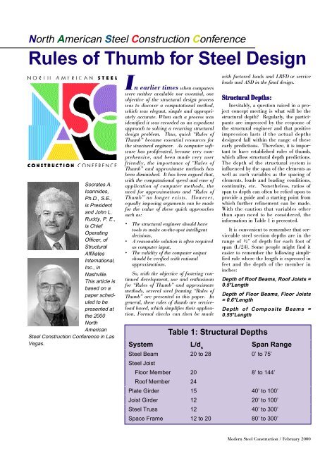
With the caution that variables other<br />
than span need to be considered, the<br />
in<strong>for</strong>mation in Table 1 is presented.<br />
It is convenient to remember that serviceable<br />
steel section depths are in the<br />
range <strong>of</strong> ½” <strong>of</strong> depth <strong>for</strong> each foot <strong>of</strong><br />
span (L/24). Some people might find it<br />
easier to remember the following simplified<br />
rule where the length is expressed in<br />
feet and the depth <strong>of</strong> the member in<br />
inches:<br />
Depth <strong>of</strong> Ro<strong>of</strong> Beams, Ro<strong>of</strong> Joists =<br />
0.5*Length<br />
Depth <strong>of</strong> Floor Beams, Floor Joists<br />
= 0.6*Length<br />
Depth <strong>of</strong> Composite Beams =<br />
0.55*Length<br />
Table 1: Structural Depths<br />
System L/d s Span Range<br />
<strong>Steel</strong> Beam<br />
<strong>Steel</strong> Joist<br />
20 to 28 0’ to 75’<br />
Floor Member 20 8’ to 144’<br />
Ro<strong>of</strong> Member 24<br />
Plate Girder 15 40’ to 100’<br />
Joist Girder 12 20‘ to 100’<br />
<strong>Steel</strong> Truss 12 40’ to 300’<br />
Space Frame 12 to 20 80’ to 300’<br />
<strong>Modern</strong> <strong>Steel</strong> <strong>Construction</strong> / February 2000
Section Properties<br />
Wide flange steel section properties<br />
can be estimated with reasonable accuracy<br />
when the member depth, width and<br />
foot-weight are known. Recalling that<br />
the density <strong>of</strong> steel is 490 pcf, the relationship<br />
between cross section area and<br />
foot-weight can readily be derived as:<br />
Wt<br />
A =<br />
3.<br />
4<br />
The strong axis moment <strong>of</strong> inertia can<br />
be approximated using:<br />
2<br />
I D<br />
x ≈<br />
The radius <strong>of</strong> gyration is an important<br />
cross section property when considering<br />
column buckling. Both the strong axis<br />
and weak axis radius <strong>of</strong> gyration can be<br />
estimated using the member depth (D)<br />
and width (b) as:<br />
r ≈ 0.<br />
26 b<br />
y<br />
r ≈ 0.<br />
45<br />
x<br />
Wt<br />
20<br />
D<br />
Beams<br />
The rapid determination <strong>of</strong> a steel<br />
section size can be made without reference<br />
to a steel manual using a very simple<br />
equation. If the moment capacity,<br />
depth and foot weight <strong>of</strong> the economy<br />
steel beams listed in the AISC<br />
Specification are tabulated with moment<br />
divided by the depth as the independent<br />
variable and foot weight as the dependent<br />
variable, a linear regression analysis<br />
results in a rather simple equation <strong>for</strong><br />
F y =36 ksi.<br />
5 M<br />
Wt ≈<br />
D<br />
The closest economy section <strong>of</strong> the<br />
depth used in the equation that has a<br />
foot weight greater than predicted by the<br />
equation indicates the beam that will sustain<br />
the moment. This equation was confirmed<br />
by the author using an alternate<br />
approach, coined “Visual Semi-rigorous<br />
Curve Fitting”3. If all the beam sections<br />
are included, a slope value in the linear<br />
equation <strong>of</strong> 5.2 yields closer approximations<br />
<strong>for</strong> F y =36 ksi.<br />
<strong>Modern</strong> <strong>Steel</strong> <strong>Construction</strong> / February 2000<br />
Consider a beam spanning 30 feet<br />
supporting a 10 foot width <strong>of</strong> floor with a<br />
total supported load <strong>of</strong> 140 psf, resulting<br />
in a moment <strong>of</strong> 157.5 foot-kips. For an<br />
18” deep beam, the equation yields 43.75<br />
pounds per foot. A W18x50 is the predicted<br />
section and the actual moment<br />
capacity is 176 foot-kips. If a beam<br />
depth <strong>of</strong> 21” is assumed, the equation<br />
yields 37.5 suggesting a W21x44, which<br />
has a moment capacity <strong>of</strong> 162 foot-kips.<br />
A similar <strong>for</strong>mulation <strong>for</strong> steel having<br />
F = 50 ksi produces:<br />
y<br />
For an 18” deep beam, the equation<br />
yields 30.6 3.5 M<br />
Wt pounds ≈ per foot, there<strong>for</strong>e, a<br />
W18x35 is predicted. D The actual capacity<br />
<strong>of</strong> a W18x35 beam with Fy=50 ksi is 158<br />
foot kips.<br />
For common composite beam floor<br />
systems (e.g. 5½” slabs with 3” composite<br />
deck, 4½” slab with 2” composite deck,<br />
etc.), the simplified equations yield relatively<br />
accurate foot weights if 70% to<br />
75% <strong>of</strong> the simple span moment is used<br />
<strong>for</strong> M. Following are two more “<strong>Rules</strong> <strong>of</strong><br />
<strong>Thumb</strong>” relating to composite construction<br />
and Fy=36:<br />
In ASD Number <strong>of</strong> shear studs<br />
required <strong>for</strong> Full Composite Action<br />
= 1.1*Wt<br />
In LRFD Number <strong>of</strong> shear studs<br />
required <strong>for</strong> Full Composite Action<br />
= 1.25*Wt<br />
COLUMNS<br />
When the column axial capacity is<br />
plotted as a function <strong>of</strong> Kl/r, an approximate<br />
linear relation can be observed.<br />
Certainly, the column curve is not linear,<br />
however an accurate approximation <strong>of</strong><br />
column capacity <strong>for</strong> Fy=36 ksi can be<br />
calculated using:<br />
⎛<br />
P ≈ A ⎜22.<br />
0 − 0.<br />
10<br />
⎝<br />
⎛<br />
P ≈ A ⎜ 30.<br />
0 − 0.<br />
15<br />
⎝<br />
Kl<br />
⎞<br />
⎟<br />
r ⎠<br />
Kl<br />
⎞<br />
⎟<br />
r ⎠<br />
A similar <strong>for</strong>mulation <strong>for</strong> steel having<br />
F y = 50 ksi produces:<br />
Thus, using the section property<br />
approximations in conjunction with a<br />
member foot-weight, width, depth and<br />
unsupported length, the capacity <strong>of</strong> a column<br />
can be approximated.<br />
Ro<strong>of</strong> Systems<br />
A common approach to economy in<br />
steel ro<strong>of</strong> systems <strong>of</strong> single story buildings<br />
is to cantilever girders over the columns.<br />
The ends <strong>of</strong> the cantilever support a<br />
reduced span beam. When this system is<br />
subjected to a uni<strong>for</strong>m load and multiple<br />
equal spans are available, a cantilever<br />
length approximately equal to 15%<br />
(0.146) <strong>of</strong> the span length will result in<br />
the maximum moment in any span being<br />
equal to 1/16 wL2. For end spans, negative<br />
and positive moments can be balanced<br />
using a cantilever length equal to<br />
25% <strong>of</strong> the first interior span.<br />
Another approach to economical ro<strong>of</strong><br />
systems is the use <strong>of</strong> plastic analysis.<br />
Although not as critical <strong>for</strong> this system,<br />
splice locations in the plastically designed<br />
continuous beams are usually chosen so<br />
that they are close to the point <strong>of</strong> zero<br />
moment.<br />
Hinge or splice location <strong>for</strong> cantilever<br />
or continuous ro<strong>of</strong> systems<br />
is 15% to 25% <strong>of</strong> span length<br />
Trusses<br />
The foot weight <strong>of</strong> trusses utilizing<br />
Fy=36 ksi steel can be calculated by<br />
assuming Fa=22 ksi. The Chord Force<br />
(Fch) is then equal to the moment (M) in<br />
foot-kips divided by de (center <strong>of</strong> top<br />
chord to center <strong>of</strong> bottom chord) in feet,<br />
resulting in a chord area <strong>of</strong> M/22de. By<br />
recognizing that Wt = A*3.4, converting<br />
de to inches and assuming that de = 0.9D<br />
and that the total truss weight is equal to<br />
3.5 times the chord weight then:<br />
The same <strong>for</strong>mulation using steel with<br />
Fy=50 ksi produces the following<br />
approximation:<br />
4.<br />
5 M<br />
Wt ≈<br />
D<br />
6 M<br />
Wt ≈<br />
D<br />
These weight approximations include<br />
truss joint connection material weight.<br />
Rigid Frame Analysis<br />
Approximations:<br />
The following “<strong>Rules</strong> <strong>of</strong> <strong>Thumb</strong>” are<br />
useful in determining preliminary sizes<br />
<strong>for</strong> Rigid Moment Frames resisting
Lateral loads. They are based on the traditional<br />
“Portal Frame” approach modified<br />
from the authors’ experiences with<br />
“real” frames.<br />
M<br />
M beam ≈<br />
M beam M col ≈<br />
1.<br />
2H<br />
V<br />
M col ≈ •<br />
2 n<br />
col<br />
2<br />
story<br />
The moments in beams framing<br />
into exterior columns are half <strong>of</strong> the<br />
above values<br />
<strong>Steel</strong> Weight Estimates<br />
Cost is generally the basis <strong>for</strong> confirming<br />
a structural system since safety and<br />
functions are essential <strong>for</strong> any options<br />
considered. Economy is related to the<br />
weight <strong>of</strong> the structural steel although<br />
costs are influenced by many other parameters.<br />
Yet, weight can be a valuable<br />
indicator <strong>of</strong> cost and <strong>Rules</strong> <strong>of</strong> <strong>Thumb</strong> are<br />
useful in establishing an expectation <strong>for</strong><br />
steel weight. A quick assessment <strong>of</strong><br />
anticipated weight serves as a check <strong>of</strong><br />
the reliability <strong>of</strong> the weight determined<br />
by more involved investigations.<br />
Bracing is a cost-effective means <strong>of</strong><br />
providing lateral load resistance <strong>for</strong> low<br />
to medium rise buildings. As the building<br />
height increases, the unit steel weight<br />
increases since columns are subjected to<br />
larger loading at the lower floors and lateral<br />
load resisting components are subjected<br />
to greater loads <strong>for</strong> greater heights.<br />
Thus, one parameter influencing the<br />
steel weight is building height. A rough<br />
approximation <strong>for</strong> steel weight per square<br />
foot in a braced building using steel with<br />
Fy = 50 ksi is:<br />
Wt(psf) = stories/3 + 7<br />
A three-story building would have a<br />
steel weight in the range <strong>of</strong> 8 psf and a<br />
27-story building would require 16 psf.<br />
Certainly, this relationship is an over<br />
simplification. Yet, it provides a value,<br />
which can be used to confirm that the<br />
results <strong>of</strong> a more detailed analysis are<br />
reasonable.<br />
col<br />
Interior Columns at Ro<strong>of</strong><br />
Interior Columns Not at Ro<strong>of</strong><br />
Tall Building Structural Systems<br />
The late Fazlur Khan hypothesized<br />
that the appropriate structural system to<br />
resist lateral loads was directly related to<br />
building height. He predicted that structural<br />
economy could be realized using<br />
the appropriate system shown in Table 2.<br />
Miscellaneous<br />
End rotation <strong>of</strong> a simple beam = 0.2<br />
radians<br />
Deflection <strong>of</strong> simple span beam (reduction<br />
due to connections) = 80% <strong>of</strong> calculated<br />
Ro<strong>of</strong> Framing Systems<br />
For Cantilevered or continuous ro<strong>of</strong><br />
beams :<br />
Run beams in short direction<br />
Optimum bay size is 30’ x 40’<br />
For Truss Joist and Joist ro<strong>of</strong> systems:<br />
Run Girders in Long direction<br />
Optimum bay size is 40’ x 40’<br />
Nomenclature<br />
Table 2: Tall Building Structural Systems<br />
Stories Lateral Load Resisting System<br />