Kuparuk River Submersible Bridge - Jesse Engineering Co.
Kuparuk River Submersible Bridge - Jesse Engineering Co.
Kuparuk River Submersible Bridge - Jesse Engineering Co.

Create successful ePaper yourself
Turn your PDF publications into a flip-book with our unique Google optimized e-Paper software.
Special Award: Special Purpose<br />
Modern Steel <strong>Co</strong>nstruction / July 2000<br />
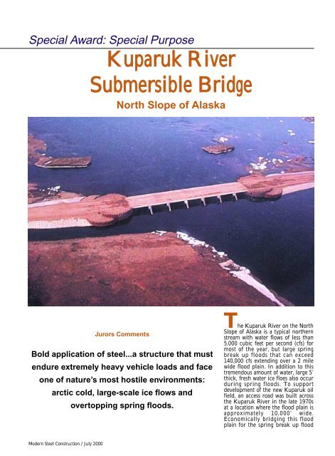
<strong>Kuparuk</strong> <strong>River</strong><br />
<strong>Submersible</strong> <strong>Bridge</strong><br />
North Slope of Alaska<br />
Jurors <strong>Co</strong>mments<br />
Bold application of steel...a structure that must<br />
endure extremely heavy vehicle loads and face<br />
one of nature’s most hostile environments:<br />
arctic cold, large-scale ice flows and<br />
overtopping spring floods.<br />
The <strong>Kuparuk</strong> <strong>River</strong> on the North<br />
Slope of Alaska is a typical northern<br />
stream with water flows of less than<br />
5,000 cubic feet per second (cfs) for<br />
most of the year, but large spring<br />
break up floods that can exceed<br />
140,000 cfs extending over a 2 mile<br />
wide flood plain. In addition to this<br />
tremendous amount of water, large 5’<br />
thick, fresh water ice floes also occur<br />
during spring floods. To support<br />
development of the new <strong>Kuparuk</strong> oil<br />
field, an access road was built across<br />
the <strong>Kuparuk</strong> <strong>River</strong> in the late 1970s<br />
at a location where the flood plain is<br />
approximately 10,000’ wide.<br />
Economically bridging this flood<br />
plain for the spring break up flood
has presented a design challenge<br />
since the original construction of this<br />
access road.<br />
For nineteen years, the gravel road at<br />
the east and west channels of the<br />
<strong>Kuparuk</strong> <strong>River</strong> was breached annually<br />
and allowed to wash out during spring<br />
breakup, resulting in a six to eight week<br />
road closure interrupting access to the<br />
<strong>Kuparuk</strong> oil field. Historically, the cost of<br />
permanent bridges to provide access to<br />
the field were found to be cost prohibitive<br />
due to extreme environmental conditions,<br />
gross vehicle loads of up to<br />
4,000,000 pounds and the river<br />
hydraulics in which large water flows<br />
must be passed during the spring floods.<br />
The innovative solution consists of submersible<br />
bridges in combination with<br />
paved roadway sections that are allowed<br />
to overtop during peak spring break-up<br />
floods.<br />
The new <strong>Kuparuk</strong> <strong>River</strong> east (210’<br />
long) and west (150’ feet long) channel<br />
submersible bridges, completed in 1999,<br />
reduce the closure period of this critical<br />
road link to a maximum of one week per<br />
year and eliminate the need to annually<br />
reconstruct the road. The cost savings of<br />
more than three million dollars per year<br />
in oil field operational and advanced<br />
material purchase costs will pay for the<br />
project cost in four years.<br />
The crossings pass the peak spring<br />
breakup flows (typically more than seven<br />
times greater than summer flows)<br />
through and across the existing Spine<br />
Road by using a combination of welded<br />
steel submersible bridges and paved low<br />
water roadways. The short-span, stout,<br />
welded steel structures are elegant in<br />
their simplicity and are a practical, costeffective<br />
answer to permanently crossing<br />
large, dynamic arctic coastal plain rivers.<br />
Design and <strong>Co</strong>nstruction<br />
The bridges are designed to support<br />
any oil field vehicle currently in operation<br />
on Alaska’s north slope. The largest<br />
of these vehicles weighs approximately<br />
3.8 million pounds while others have<br />
maximum wheel loads that exceed 370<br />
kips (185 tons). The entire load carrying<br />
capacity of the bridge is provided by the<br />
welded steel structure. The concrete deck<br />
was provided as a driving surface, for lateral<br />
buckling support of girders, and to<br />
ensure composite action for horizontal<br />
loads and lateral ice loads.<br />
Environmental loads for the bridge<br />
consist of wind, seismic, river current,<br />
buoyant and river ice loading. For this<br />
design, wind, seismic, current and buoyant<br />
forces were insignificant when compared<br />
to the ice loading. Design ice<br />
thickness was 52” of hard structural ice<br />
(5’ total nominal ice thickness) that is<br />
capable of imposing tremendous loads on<br />
the bridge deck and ice breakers.<br />
The bridge substructure consists of<br />
large diameter, heavy wall and welded<br />
steel pipe piles—the only practical<br />
method to support the massive vehicle<br />
loads. Each pile bent, spaced at 30’ consists<br />
of four vertical 36” diameter, 1” wall<br />
API 5LX-52 pipe piles driven to 80’ penetration<br />
to support the heavy vehicle<br />
loads and provide lateral support for ice<br />
loads. Required vertical capacity (design<br />
load) of each pile was 750 kips (375 tons)<br />
which was easily achieved using a<br />
Delmag D-62 diesel impact hammer,<br />
rated at 165,000 foot-pounds of energy.<br />
Each in stream pile bent has a steel ice<br />
breaking pipe installed at 45 degrees on<br />
the upstream side. When impacted by an<br />
ice floe, this design will fail the ice sheet<br />
in bending, rather than crushing, substantially<br />
reducing the lateral force on a<br />
single ice breaker from approximately<br />
750 kips to 320 kips. This unique design<br />
saved time and cost by reducing the ice<br />
loads to the structure, providing reasonable<br />
tolerances for field fit-up and utilizing<br />
a vertical pile in lieu of more expensive<br />
and impractical (for installation in<br />
hard permafrost) batter piles.<br />
The pipe piles were slotted at cut off<br />
to receive the steel box pile cap. The slotted<br />
pile to pile cap connection provided<br />
both a full moment connection for lateral<br />
load resistance and the load transfer for<br />
vertical loads, eliminating the need for<br />
bearing stiffeners. <strong>Co</strong>st saving 1½” interior<br />
bearing stiffeners attached to the top<br />
flange of the pile cap also eliminated the<br />
need for bearing stiffeners in the girders.<br />
The bridge abutment design utilizes<br />
open sheet pile cellular structures, a<br />
rugged and proven innovation utilized<br />
throughout the Pacific Northwest. These<br />
abutments are constructed in a circular<br />
arc in which the sheet pile cell remains<br />
unclosed beneath the roadway. As is<br />
found in closed cellular structures, hoop<br />
stresses are generated between the sheet<br />
piles, but with the open cell abutments<br />
the hoop stress is resisted solely by soil<br />
friction along at the tail ends of the structure.<br />
For these submerged structures, the<br />
tail ends of the central cell (tailwalls)<br />
were protected from scour by inclusion of<br />
short wingwalls on the upstream and<br />
downstream sides. Wingwalls were constructed<br />
in a circular pattern and behave<br />
in the same manner as the central sheet<br />
pile cell. This abutment type is not scour<br />
sensitive since sheet pile embedment at<br />
the streamside face is not required for<br />
the abutment stability.<br />
The submersible bridge design utilizes<br />
30’ spans that allow an extremely shallow,<br />
high-capacity deck and girder system.<br />
The superstructure consists of<br />
eleven 22½” deep steel plate girders at 3’<br />
spacing encased in cast-in-place structural<br />
concrete. The girders were constructed<br />
using ASTM A572, Grade 50 material<br />
meeting Charpy V-notch impact criteria<br />
of 15/12 (avg./min.) foot-pounds at -50°<br />
F for cold weather performance.<br />
The steel structure also served as<br />
formwork for the superstructure concrete<br />
by eliminating the need for falsework and<br />
minimizing on-site construction time and<br />
costs. A 26” diameter fabricated steel<br />
half-pipe deck nose is welded to the edge<br />
of the upstream girder to provide a round<br />
surface that further limits ice crushing<br />
loads on the deck. The deck nose is fitted<br />
with guardrail support pipes that are<br />
welded to the outside girders. A rolled<br />
plate welded to the downstream girder<br />
Modern Steel <strong>Co</strong>nstruction / July 2000
provided the concrete formwork on the<br />
other side of the bridge. Steel plate<br />
placed on the bottom flange of the plate<br />
girders and attached with intermittent fillet<br />
welds served as the underside concrete<br />
form for the bridge.<br />
The bridge design required an easily<br />
removable guardrail for the crossing of<br />
oilfield vehicles up to 60’ wide. Welded<br />
steel pipe sleeves at the edges of the deck<br />
provide support for the removable<br />
guardrails. The identical sections of<br />
guardrail, each fourteen feet long, are<br />
easily removed and replaced as the pipe<br />
legs slide into the pipe supports in the<br />
bridge deck. This system has received<br />
much praise for its ease of use, especially<br />
in extremely cold weather.<br />
Fabrication<br />
Fabrication of welded steel bridge<br />
components was a critical element to the<br />
success of this project. All of the components<br />
of the bridge were shop fabricated<br />
into sections that were easily transported<br />
to the site to minimize costs. Both the<br />
design engineer and general contractor<br />
worked carefully with the fabricator to<br />
assure that all fabricated pieces would be<br />
easily erected in the field. Careful match<br />
marking of each fabricated member and<br />
the fabricator’s careful attention to detail<br />
allowed the structure to be erected in<br />
temperatures averaging -30° F and wind<br />
speeds of up to 20 mph without requiring<br />
field modifications.<br />
<strong>Co</strong>nclusion<br />
By utilizing a combination of durable,<br />
submersible bridges and paved low water<br />
roadways an innovative solution was<br />
developed to provide reliable access to<br />
the <strong>Kuparuk</strong> oil field for 51 weeks out of<br />
the year. The unique design kept the cost<br />
of the project within reasonable limits for<br />
crossing two river channels in a flood<br />
plain over two miles wide. The project<br />
was designed and constructed on time<br />
with a tremendous cost savings over traditional,<br />
elevated bridge designs. This<br />
successful design promises to serve as a<br />
model for future expansion of the infrastructure<br />
on the North Slope of Alaska<br />
and in other climates around the world.<br />
Project Team<br />
Owner<br />
Phillips Alaska, Inc.<br />
Designer<br />
Peratrovich, Nottingham, &<br />
Drage<br />
Steel Fabricators<br />
<strong>Jesse</strong> <strong>Engineering</strong> <strong>Co</strong>mpany<br />
General <strong>Co</strong>ntractor<br />
Alaska Interstate<br />
<strong>Co</strong>nstruction