Under Foot - Modern Steel Construction
Under Foot - Modern Steel Construction
Under Foot - Modern Steel Construction

You also want an ePaper? Increase the reach of your titles
YUMPU automatically turns print PDFs into web optimized ePapers that Google loves.
ONE OF ThE MOST NEgLECTED ELEMENTS in the design<br />
of buildings is the horizontal floor diaphragm and its interaction<br />
with the lateral load resisting systems. Most multi-story structures<br />
depend on the floor slab and roof systems to act as horizontal diaphragms<br />
to collect and distribute the lateral loads to the vertical<br />
framing members, which provide the overall structural stability.<br />
In steel structures, floor diaphragms are most commonly constructed<br />
using composite steel deck with concrete fill, although<br />
other systems, such as pre-cast planks, formed reinforced concrete,<br />
or concrete on non-composite steel deck, may also be used. While<br />
there are numerous references that discuss the design of the diaphragm<br />
itself, there is little guidance available on the transfer of<br />
diaphragm forces into the lateral load resisting system. In addition,<br />
the specific issues related to beam design for members collecting<br />
lateral loads in composite floor systems has gone largely undocumented.<br />
The intent of this article is to help “fill in the gaps” on<br />
these issues through a discussion of the effect of diaphragm forces<br />
on the supporting steel beam behavior, as well as through practical<br />
detailing guidelines.<br />
general Diaphragm Behavior<br />
Before delving into the specific issues associated with the<br />
transfer of diaphragm forces to the supporting framing, it is necessary<br />
to understand general diaphragm behavior and how assumptions<br />
made affect the detailing required in establishing a robust<br />
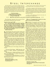
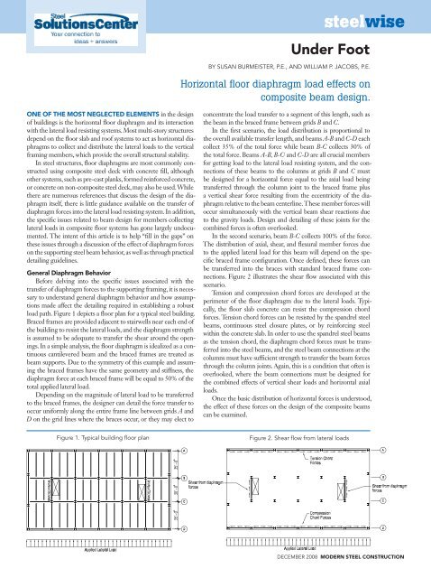
load path. Figure 1 depicts a floor plan for a typical steel building.<br />
Braced frames are provided adjacent to stairwells near each end of<br />
the building to resist the lateral loads, and the diaphragm strength<br />
is assumed to be adequate to transfer the shear around the openings.<br />
In a simple analysis, the floor diaphragm is idealized as a continuous<br />
cantilevered beam and the braced frames are treated as<br />
beam supports. Due to the symmetry of this example and assuming<br />
the braced frames have the same geometry and stiffness, the<br />
diaphragm force at each braced frame will be equal to 50% of the<br />
total applied lateral load.<br />
Depending on the magnitude of lateral load to be transferred<br />
to the braced frames, the designer can detail the force transfer to<br />
occur uniformly along the entire frame line between grids A and<br />
D on the grid lines where the braces occur, or they may elect to<br />
steelwise<br />
<strong>Under</strong> <strong>Foot</strong><br />
by SuSan burmeiSter, P.e., and William P. JacobS, P.e.<br />
Horizontal floor diaphragm load effects on<br />
composite beam design.<br />
concentrate the load transfer to a segment of this length, such as<br />
the beam in the braced frame between grids B and C.<br />
In the first scenario, the load distribution is proportional to<br />
the overall available transfer length, and beams A-B and C-D each<br />
collect 35% of the total force while beam B-C collects 30% of<br />
the total force. Beams A-B, B-C, and C-D are all crucial members<br />
for getting load to the lateral load resisting system, and the connections<br />
of these beams to the columns at grids B and C must<br />
be designed for a horizontal force equal to the axial load being<br />
transferred through the column joint to the braced frame plus<br />
a vertical shear force resulting from the eccentricity of the diaphragm<br />
relative to the beam centerline. These member forces will<br />
occur simultaneously with the vertical beam shear reactions due<br />
to the gravity loads. Design and detailing of these joints for the<br />
combined forces is often overlooked.<br />
In the second scenario, beam B-C collects 100% of the force.<br />
The distribution of axial, shear, and flexural member forces due<br />
to the applied lateral load for this beam will depend on the specific<br />
braced frame configuration. Once defined, these forces can<br />
be transferred into the braces with standard braced frame connections.<br />
Figure 2 illustrates the shear flow associated with this<br />
scenario.<br />
Tension and compression chord forces are developed at the<br />
perimeter of the floor diaphragm due to the lateral loads. Typically,<br />
the floor slab concrete can resist the compression chord<br />
forces. Tension chord forces can be resisted by the spandrel steel<br />
beams, continuous steel closure plates, or by reinforcing steel<br />
within the concrete slab. In order to use the spandrel steel beams<br />
as the tension chord, the diaphragm chord forces must be transferred<br />
into the steel beams, and the steel beam connections at the<br />
columns must have sufficient strength to transfer the beam forces<br />
through the column joints. Again, this is a condition that often is<br />
overlooked, where the beam connections must be designed for<br />
the combined effects of vertical shear loads and horizontal axial<br />
loads.<br />
Once the basic distribution of horizontal forces is understood,<br />
the effect of these forces on the design of the composite beams<br />
can be examined.<br />
Figure 1. typical building floor plan Figure 2. Shear flow from lateral loads<br />
december 2008 MODERN STEEL CONSTRUCTION
Additional Shear Connection?<br />
The mechanical connection of the floor<br />
system to the supporting steel beams in a composite<br />
beam system is achieved using headed<br />
steel studs or hot-rolled channel shear connectors.<br />
Often, the beams are designed as composite<br />
members for the gravity loads applied to<br />
the floor system. Traditionally, if the beam also<br />
serves as a collector element, additional shear<br />
studs are added to account for transfer of the<br />
superimposed horizontal load into the beam.<br />
However, this practice is not always necessary<br />
for two primary reasons.<br />
First, the quantity of shear studs selected<br />
for a composite beam is usually determined<br />
based on a gravity load combination, such<br />
as 1.2D+1.6L (LRFD) or 1.0D+1.0L (ASD).<br />
When lateral loads are applied in conjunction<br />
with the gravity loads, the load combinations<br />
of ASCE 7 reduce the live load levels. <strong>Under</strong><br />
these reduced live loads, the shear studs provided<br />
to develop the composite action required<br />
for the gravity loads will be under-used and<br />
thus have additional capacity available for the<br />
transfer of the diaphragm forces.<br />
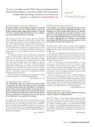
Second, the interaction of the shear flow<br />
from the different loading conditions is additive<br />
for some studs but opposite for others. The<br />
distribution of horizontal shear from beam<br />
flexure is assumed to flow in two directions<br />
from the point of maximum moment to the<br />
point of zero moment. For a typical simplespan<br />
composite beam with uniform gravity<br />
loads, this shear flow is as indicated in Figure 3.<br />
While the beam shear is greatest at the ends<br />
of the beams, it is common practice to assume<br />
that the shear studs will deform and redistribute<br />
the shear uniformly to all studs.<br />
Conversely, lateral loads induce shear in<br />
only one direction. When these beams are used<br />
to collect the diaphragm forces, the shears due<br />
to the lateral loads are superimposed on the<br />
horizontal shears due to the gravity loads, as<br />
indicated in Figure 4. On one side of the beam,<br />
the lateral loads increase the horizontal shears<br />
over the gravity-induced values, while on the<br />
other side of the beam, the lateral loads oppose<br />
the gravity-induced horizontal shears.<br />
Assuming the shear studs have sufficient<br />
ductility to distribute the horizontal shears<br />
evenly along the beam, a composite beam can<br />
transfer a horizontal shear due to lateral loads<br />
between the floor diaphragm and steel beam<br />
that is equal to the summation of the strengths<br />
of all the shear studs on the beam regardless<br />
MODERN STEEL CONSTRUCTION december 2008<br />
of demand on the shear studs from the gravity<br />
loads.<br />
“Non-Composite” Composite Beams<br />
Designers encounter many conditions<br />
where steel beams are designed as non-composite<br />
members under gravity loads. Shear<br />
studs placed on these beams for transfer of lateral<br />
forces still will be subjected to horizontal<br />
shears due to flexure from gravity loads. This<br />
is unavoidable. Therefore, in order to ensure<br />
the anchors are not overloaded under the gravity<br />
loads, it is recommended that all beams<br />
that transfer diaphragm forces to the lateral<br />
load resisting systems have enough anchors<br />
to achieve a minimum 25% partial composite<br />
action. When less anchors than this are<br />
provided, large deformations of the studs may<br />
occur under the gravity load case, inhibiting<br />
the ability of the beam to function as intended<br />
under lateral loading.<br />
To Phi or not to Phi?<br />
The nominal strength of the individual<br />
shear studs, Q n, can be determined from the<br />
equations in the AISC Specification. The current<br />
shear connector strength equations<br />
generally are used as nominal strength equations<br />
in composite beam design where the<br />
anchors are part of a composite system; the φ<br />
and Ω come in later in the calculation of the<br />
beam flexural strength. However, when the<br />
shear stud strength is checked as a connection<br />
between the diaphragm and beam, a resistance<br />
(or safety) factor should be applied to the shear<br />
stud nominal strength. Based on preliminary<br />
results of ongoing research at the University<br />
of Illinois at Urbana-Champaign, φ = 0.65<br />
(LRFD) or Ω = 2.30 (ASD) are recommended.<br />
These values are in line with similar recommendations<br />
by PCI and ACI.<br />
Secondary Shears and Moments<br />
Once the designer deals with the transfer<br />
of force from the floor diaphragm into the<br />
supporting steel beam, the effect of the diaphragm<br />
forces on the design of the beam and<br />
its connections to the remainder of the lateral<br />
load resisting system must be considered. Of<br />
particular concern is the effect of the vertical<br />
offset (eccentricity) between the plane of the<br />
diaphragm and the centerline of the supporting<br />
beam as indicated in Figure 5. Intuitively,<br />
one would anticipate additional moments<br />
imposed on the beam as a result of the eccentricity.<br />
However, this is not the case.<br />
As an example, consider a simple-span<br />
beam with uniform horizontal shears from the<br />
lateral loads and resulting reactions as shown in<br />
Figure 5. For this scenario, assume the member<br />
is connected to the lateral load resisting system<br />
at the left end of the beam only.<br />
The free body diagram in Figure 6 shows<br />
the internal member forces that result from<br />
this applied uniform load. The axial load in<br />
the beam will increase linearly toward the end<br />
of the beam designed to transfer the collected<br />
force to the lateral load resisting system, but<br />
the internal moment due to this applied lateral<br />
load, even considering the d/2 eccentricity,<br />
will be zero. The member should be designed<br />
as a beam-column, considering the combined<br />
effects of the axial forces due to the lateral loads<br />
and the flexural forces due only to the gravity<br />
loads. The shear is a constant value and must<br />
be considered in the connection design at both<br />
ends of the member.
Force Interaction<br />
The rigorous design of composite beams for combined axial force and<br />
flexure is complex. As a reasonable simplification for design purposes, it<br />
is acceptable to use the non-composite axial strength and the composite<br />
flexural strength in combination using the interaction equations in the<br />
AISC Specification, Chapter H. Note that for compressive loading, this<br />
type of composite beam-column is generally considered unbraced for<br />
buckling between braced points about the major axis, and fully braced by<br />
the composite diaphragm for buckling about the minor axis.<br />
As with all structural systems, there is an element of engineering<br />
judgment involved in the proper design and detailing of horizontal diaphragms<br />
and composite beam interaction. Careful consideration should<br />
be made to provide a continuous load path. The designer must account<br />
for the required axial forces and shears to be transferred at the end connections<br />
of all beams. Though there are many aspects to consider for<br />
the design of composite beams subject to horizontal diaphragm forces<br />
as reviewed in this article, their implementation is straightforward, thus<br />
allowing the composite beams to be used as an economical and efficient<br />
component of the lateral force resisting system.<br />
Susan Burmeister is an associate with Cagley and Associates, Inc., Rockville, Md.,<br />
and William P. Jacobs is a design engineer with SDL Structural Engineers,<br />
Atlanta.<br />
Fig. 5. analytical model of simple span beam<br />
Fig. 6. Free body diagram of beam segment<br />
(Fig. 3)<br />
(Fig. 4)<br />
lateral loads increase net<br />
shear in steel anchors<br />
within this zone<br />
Shear flow from lateral loads<br />
(Fig. 5)<br />
(Fig. 6)<br />
beam<br />
lateral loads decrease<br />
net shear in steel anchors<br />
within this zone<br />
Shear flow from gravity loads<br />
Fig. 3. Shear flow due to gravity loads only<br />
Fig. 4. Shear flow due to gravity and lateral loads in combination