Ramp structural analysis - Modern Steel Construction
Ramp structural analysis - Modern Steel Construction
Ramp structural analysis - Modern Steel Construction

You also want an ePaper? Increase the reach of your titles
YUMPU automatically turns print PDFs into web optimized ePapers that Google loves.
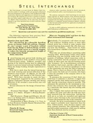
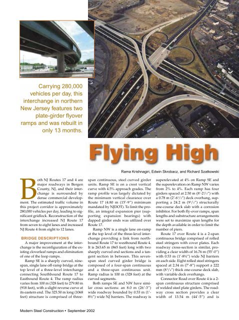
Carrying 280,000<br />
vehicles per day, this<br />
interchange in northern<br />
New Jersey features two<br />
plate-girder flyover<br />
ramps and was rebuilt in<br />
only 13 months.<br />
Both NJ Routes 17 and 4 are<br />
major roadways in Bergen<br />
County, NJ, and their interchange<br />
is surrounded by<br />
dense commercial development.<br />
The estimated traffic volume in<br />
this project corridor is approximately<br />
280,000 vehicles per day, leading to significant<br />
gridlock. Reconstruction of the<br />
interchange increased NJ Route 17<br />
from seven to eight lanes and increased<br />
NJ Route 4 from eight to 12 lanes.<br />
BRIDGE DESCRIPTIONS<br />
A major improvement at the interchange<br />
is the reconfiguration of the existing<br />
cloverleaf ramps and elimination<br />
of one of the loop ramps.<br />
<strong>Ramp</strong> SE is a sharply curved, ninespan,<br />
single lane off-ramp bridge at the<br />
top level of a three-level interchange<br />
connecting Southbound Route 17 to<br />
Eastbound Route 4. The ramp radius<br />
varies from 100 m (328 feet) to 279.80 m<br />
(918 feet), with a slight reverse curve at<br />
its eastern end. The 325.50 m long (1068<br />
feet) structure is comprised of three-<br />
<strong>Modern</strong> <strong>Steel</strong> <strong>Construction</strong> • September 2002<br />
span continuous, steel curved girder<br />
units. <strong>Ramp</strong> SE is on a crest vertical<br />
curve with 4.5% approach grades. The<br />
ramp profile was largely dictated by<br />
the minimum vertical clearance over<br />
Route 17 (4.80 m (15’-9”) minimum<br />
mandated by NJDOT). To limit the profile,<br />
an integral expansion pier (supporting<br />
expansion bearings) with<br />
dapped girder ends was utilized over<br />
Route 17.<br />
<strong>Ramp</strong> NW is a single lane on-ramp<br />
at the top level of the three-level interchange<br />
providing a link from northbound<br />
Route 17 to westbound Route 4.<br />
It is 263.65 m (865 feet) long with two<br />
sharply curved end sections and a tangent<br />
section in between. This sevenspan<br />
steel curved girder bridge is<br />
composed of a four-span continuous<br />
and a three-span continuous unit.<br />
<strong>Ramp</strong> radius is 100 m (328 feet) at the<br />
curved segments.<br />
Both ramps SE and NW have similar<br />
cross sections: an 8.0 m (26’-3”)<br />
wide roadway bounded by 0.53 m (1’-<br />
8½”) wide NJ barriers. The roadway is<br />
Rama Krishnagiri, Edwin Skrobacz, and Richard Szatkowski<br />
superelevated at 4% on <strong>Ramp</strong> SE and<br />
the superelevation on <strong>Ramp</strong> NW varies<br />
from 2% to 4%. Each ramp has four<br />
girders spaced at 2.50 m (8’-2 1 /2”) with<br />
a 0.78 m (2’-6 1 /2”) deck overhang, supporting<br />
a 24.2 m (9 1 /2”) <strong>structural</strong>ly<br />
one-course deck slab with a corrosion<br />
inhibitor. For both fly-over ramps, span<br />
lengths and substructure arrangements<br />
were set to maximize span lengths for<br />
the depth available in order to limit the<br />
number of piers.<br />
Route 17 over Route 4 is a 2-span<br />
continuous bridge comprised of rolled<br />
steel stringers with cover plates. Each<br />
roadway cross-section is similar, providing<br />
a clear width of 16.76 m (55’-0”)<br />
with 0.53 m (1’-8½”) wide NJ barriers<br />
on each side. Eight rolled steel stringers<br />
spaced at 2.34 m (7’-8”) support a 222<br />
mm (8 3 /4”) thick one-course deck slab,<br />
with variable deck overhangs.<br />
Connector Road over Route 4 is a 2span<br />
continuous structure comprised<br />
of welded steel plate girders. The roadway<br />
cross section provides a clear<br />
width of 13.54 m (44’-5”) and is
ounded by a 0.53 m (1’-8 1 /2”) wide NJ<br />
barrier on one side and a 1.83 m (6’-0”)<br />
wide sidewalk and 0.31 m (1’-0”) wide<br />
parapet on the other side. Seven steel<br />
welded plate girders spaced at 2.44 m<br />
(8’-0”) on centers support the 216 mm<br />
(8 1 /2”) thick single course deck slab.<br />
DESIGN CONSIDERATIONS<br />
During the conceptual stage of the<br />
project different span arrangements<br />
and structure types were evaluated for<br />
each bridge. Due to right-of-way limitations,<br />
long retaining walls were necessary<br />
at several locations. Therefore,<br />
limiting the total superstructure depth<br />
was very important in order to keep<br />
the profile low. For Route 17 crossing<br />
over Route 4 and the connector bridge<br />
over Route 4, a comparative study indicated<br />
that a two-span continuous<br />
steel superstructure would provide a<br />
shallower depth than prestressed concrete.<br />
For the curved ramp structures, a<br />
continuous steel superstructure with<br />
curved girders integral with the pier<br />
cap for the pier on Route 17 provided<br />
the most economical type of structure.<br />
For redundancy, a multi-girder superstructure<br />
was chosen. For economy of<br />
details and ease and speed of fabrication/construction,<br />
the steel fabricating<br />
industry was consulted during the preliminary<br />
and final design phases.<br />
RAMP STRUCTURAL ANALYSIS<br />
Due to the complex geometry and<br />
the presence of integral piers, a tested<br />
and reliable computer program was required<br />
for <strong>analysis</strong> and design. The<br />
ramp bridges were analyzed and designed<br />
using a three-dimensional, finite<br />
element program developed by<br />
BSDI, Ltd. The program allows a detailed<br />
<strong>analysis</strong> at various stages, including<br />
construction condition, e.g.,<br />
girder erection stage and effects on the<br />
superstructure prior to placing the concrete<br />
deck, effects of placing the deck<br />
for specified sequences of concrete<br />
placement, and also if the deck concrete<br />
were to be placed all at once. The<br />
effects of thermal loading were also included<br />
as a separate load condition.<br />
The <strong>analysis</strong> included the stiffness<br />
of the deck slab and the entire superstructure<br />
was analyzed as a total system,<br />
including the deck, girders, cross<br />
frames, and bearings. From the input<br />
data supplied, the program creates finite-element<br />
models considering non-<br />
composite and composite <strong>structural</strong> behavior.<br />
Girder flanges were modeled<br />
with beam elements, webs using shell<br />
elements, and cross frames were modeled<br />
using truss elements. The deck<br />
slab was modeled using eight-node<br />
solid elements and connected to the<br />
girder top flange with beam elements<br />
for the shear studs. For the design in<br />
negative moment regions, as mandated<br />
by NJDOT, the contribution of the deck<br />
reinforcement steel was ignored; however<br />
for live load and superimposed<br />
dead load distribution, the composite<br />
action was included.<br />
For the integral fixed pier, a special<br />
<strong>analysis</strong> was performed where the<br />
model included the pier as an integral<br />
part of the superstructure. The pier column<br />
was modeled to a “point of fixity”.<br />
Thus the model recognized the<br />
effect of pier stiffness on the superstructure.<br />
HS25 was the specified live loading<br />
for design. Maximum and minimum<br />
responses for the moments, shears and<br />
torques were included in the <strong>analysis</strong><br />
output.<br />
Girder design was an iterative, interactive<br />
procedure performed using<br />
the responses stored at each nodal<br />
point. Curve fitting techniques were<br />
utilized internally by the program to<br />
check responses at any intermediate<br />
point along the girder. For each point<br />
checked, a constructability check was<br />
performed to check for lateral flange<br />
stability.<br />
The program included the effect of<br />
different stiffnesses of girder sections<br />
for successive pours. For this scenario,<br />
top of deck stresses of staged deck<br />
placement were carefully reviewed to<br />
avoid tensile cracks during subsequent<br />
deck placement.<br />
<strong>Ramp</strong> SE/<strong>Ramp</strong> NW: The design<br />
was performed using the AASHTO<br />
Guide Specifications for Horizontally<br />
Curved Bridges. Allowable Stress Design,<br />
then mandated by NJDOT (currently<br />
NJDOT utilizes LRFD<br />
methodology) was used.<br />
All the <strong>structural</strong> steel for the girders,<br />
bearings, and bearing stiffeners<br />
was specified to be Grade 50, while<br />
Grade 36 steel was used for cross<br />
frames and connection plates. For<br />
economy of fabrication, the web plates<br />
were specified to be of the same thickness<br />
throughout, with no intermediate<br />
stiffeners. An evaluation of reducing<br />
web plate thickness using transverse<br />
intermediate stiffeners favored the former<br />
option, since the reduction in material<br />
costs would be offset by the<br />
additional cost of welding and testing.<br />
The total length of curved girders<br />
for the two ramps is 2,377.5 m (7800<br />
feet) (1280.2 m (4200 feet) at <strong>Ramp</strong> SE,<br />
1,097.3 m(3600 feet) at <strong>Ramp</strong> NW). For<br />
economy of fabrication of the flange<br />
plates, a minimal number of plate<br />
thicknesses were specified. Since the<br />
flange plates had to be cut individually<br />
due to the different curvature on each,<br />
by using the same thickness and varying<br />
the flange widths from girder to<br />
girder line within the span, only five<br />
different flange plate thicknesses were<br />
sufficient for both of the ramp bridges.<br />
The girders typically utilized fillet<br />
welds throughout. If the fabricator required<br />
flange or web plate shop welds,<br />
full penetration butt welds (B-L2C-S or<br />
B-U3C-S) were specified. However, for<br />
the plate thickness and lengths shown<br />
on the plans it was verified during the<br />
design phase that the lengths were readily<br />
available. No butt-welded shop<br />
splices were submitted by the fabricator.<br />
For further economy, locations of the<br />
field splices were slightly adjusted from<br />
their theoretical locations (at or near<br />
dead load contraflexure) so that the<br />
lengths of as many plates as possible<br />
could be the same or nearly so within<br />
any span, in order to minimize waste<br />
during cutting of the individual flanges.<br />
Extending the thicker plate from the<br />
piers to the adjacent field splice in the<br />
span was slightly cheaper at almost all<br />
locations than introducing a flange<br />
thickness transition with a shop butt<br />
weld. Therefore, for overall economy<br />
and speed of fabrication, the change in<br />
flange plate thickness was always<br />
achieved at the field splice location.<br />
Although the flange plate widths<br />
varied, the field splice plate thicknesses<br />
and widths were kept the same at all<br />
locations for economy of fabrication. At<br />
the few locations where a change was<br />
necessary, only the splice plate length<br />
was changed. All interior cross frames<br />
were detailed identical for repetitious<br />
fabrication. K-frame cross frames were<br />
typically used at all locations, and<br />
slightly modified to support the deck<br />
joints. No fatigue detail greater than<br />
Category C was specified anywhere on<br />
the superstructure and a careful consideration<br />
during shop drawing review<br />
September 2002 <strong>Modern</strong> <strong>Steel</strong> <strong>Construction</strong>
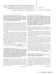
Detail of dapped girder end, necessary due to vertical clearance requirements.<br />
phase resulted in no detail exceeding<br />
Category C.<br />
Dead load camber and primary moments<br />
and shears were listed at every<br />
tenth point along each girder. To extract<br />
and customize the required values<br />
from the output of the design software,<br />
spreadsheets were developed in-house.<br />
CONSTRUCTION PHASE<br />
The construction phase began with<br />
the opening of the bid documents by<br />
NJDOT on September 10, 1998. Working<br />
in a congested area required the<br />
contractor to devote special attention to<br />
the maintenance of traffic and to community<br />
awareness due to the high impact<br />
on traffic flow. Six bids were<br />
received, ranging from $49.7 million to<br />
$72.6 million. The engineer’s estimate<br />
for the project was $61.6 million, which<br />
included 10% for contingencies.<br />
Total <strong>structural</strong> steel quantities of<br />
Grade 36 was 298,000 lb for curved<br />
girders ($0.84/lb) and 112,000 lb for<br />
straight girders ($0.98/lb). The total<br />
quantity of Grade 50 steel was<br />
2,600,000 at the curved ramps<br />
($1.06/lb), and 1,716,000 lb at straight<br />
bridges ($0.97/lb).<br />
The first shop drawings and requests<br />
for information were received in<br />
early October, 1998. NJDOT had significantly<br />
reduced their preliminary estimated<br />
construction schedule of 54<br />
months to only 30 months by the time<br />
the bid documents were opened by<br />
changing several sequential construction<br />
activities to overlapping ones and<br />
by implementing a thorough constructability<br />
review. To further reduce<br />
the schedule, they offered the contractor<br />
a $3.5 million bonus if the 30-month<br />
schedule could be reduced to 23<br />
months. After only four months of<br />
<strong>Modern</strong> <strong>Steel</strong> <strong>Construction</strong> September 2002<br />
work the contractor felt confident<br />
enough to request that a second bonus<br />
be given if they were able to cut one<br />
more year from the schedule. An agreement<br />
was reached for another $3.5 million<br />
incentive bonus for completion by<br />
November 23, 1999. The contractor was<br />
able to accomplish this goal, which<br />
compressed the original construction<br />
schedule of 30 months down to only 13<br />
months. These changes to the construction<br />
schedule required the design team<br />
to accelerate their review of the shoprequiring<br />
long hours to keep pace with<br />
the contractor’s construction activities.<br />
STEEL ERECTION<br />
The erection of the <strong>structural</strong> steel<br />
for the curved viaducts required careful<br />
planning and close coordination.<br />
Several girder picks had to be made<br />
during overnight off-peak hours due to<br />
traffic considerations. Several large<br />
cranes were required.<br />
In general, most of the field sections<br />
for the steel were pre-assembled on the<br />
ground in pairs. Ground splices were<br />
blocked and fully torqued in accordance<br />
with slip critical criteria. The<br />
contractor chose to not fully tighten the<br />
diaphragm connection bolts on the<br />
ground so as to allow additional tolerance<br />
during erection. Since the entire<br />
superstructure was modeled as a unit,<br />
the contractor was required to survey<br />
the top of girder elevations after steel<br />
erection for conformance with theoretical<br />
values.<br />
CONCLUSION<br />
This complex project was completed<br />
well ahead of the estimated schedule<br />
through a team effort on the part of the<br />
contractor, design team, and the owner,<br />
resulting in a very satisfied and happy<br />
motoring public. A significant relief to<br />
the peak-hour volume of traffic has occurred,<br />
and the numerous business<br />
owners in the shopping malls have also<br />
benefited. Although the contractor bid<br />
the project at cost, he gained a significant<br />
incentive bonus of $7 million (approximately<br />
15% of his bid cost), while<br />
the owner was very happy to see the<br />
project completed so far ahead of<br />
schedule.<br />
Rama Krishnagiri and Edwin Skrobacz<br />
are Supervising Structural Engineers<br />
and Richard Szatkowski is a Lead Structural<br />
Engineer with Parsons-Brinckerhoff,<br />
Princeton, NJ.<br />
OWNER<br />
New Jersey Department of<br />
Transportation<br />
STRUCTURAL ENGINEER<br />
Parsons-Brinckerhoff, Princeton, NJ<br />
STEEL DETAILER<br />
High <strong>Steel</strong> Structures, Inc.,<br />
Lancaster, PA (AISC member)<br />
STEEL FABRICATOR<br />
High <strong>Steel</strong> Structures, Inc.,<br />
Lancaster, PA (AISC member)<br />
GENERAL CONTRACTOR<br />
Joint venture:<br />
Bishop-Sanzari, White Plains, NY and<br />
Fletcher Creamer Inc., Hackensack, NJ<br />
ENGINEERING SOFTWARE<br />
BSDI 3D System