IDEAS 2 - Modern Steel Construction
IDEAS 2 - Modern Steel Construction
IDEAS 2 - Modern Steel Construction

Create successful ePaper yourself
Turn your PDF publications into a flip-book with our unique Google optimized e-Paper software.
Innovative Design in Engineering and architecture with Structural <strong>Steel</strong><br />
awards<br />
awards<br />
<strong>IDEAS</strong>awards 2<br />
2010 <strong>IDEAS</strong> 2 Awards Jury<br />
Todd Alwood, LEED aP, manager of Certification Business<br />
Development, aISC, Chicago<br />
Mitchell A. hirsch, aIa, Principal, Pelli Clarke Pelli<br />
architects, New Haven, Conn.<br />
Brad Lange, Pre-<strong>Construction</strong> manager, <strong>Construction</strong><br />
Products Distributors (a Weitz Company), Des moines, Iowa<br />
Mary Beth Malone, Partner, Elysian Hotels, Chicago<br />
Jack Petersen, P.E., Principal; martin/martin, Inc.,<br />
Lakewood, Colo.<br />
Jennifer Richmond, Vice President of Project management,<br />
Novel Iron Works, Inc., Greenland, N.H.<br />
Tudor Van hampton, Chicago Bureau Chief, Engineering<br />
News Record (ENR)<br />
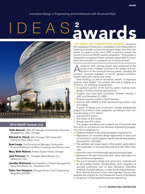
ThE DESIgN AND CONSTRUCTION INDUSTRy recognizes<br />
the importance of teamwork, coordination, and collaboration in<br />
fostering successful construction projects today more than ever<br />
before. In support of this trend, aISC is proud to present the<br />
results of its annual IDEaS² awards competition. This program is<br />
designed to recognize all team members responsible for excellence<br />
and innovation in a project’s use of structural steel.<br />
awards for each winning project were presented to the<br />
project team members involved in the design and construction<br />
of the structural framing system, including the<br />
architect, structural engineer of record, general contractor,<br />
detailer, fabricator, erector and owner.<br />
New buildings, as well as renovation, retrofit, or expansion<br />
projects, were eligible. The projects also had to display, at a<br />
minimum, the following characteristics:<br />
➜ a significant portion of the framing system must be wideflange<br />
or hollow structural steel sections;<br />
➜ Projects must have been completed between January 1,<br />
2007 and December 31, 2009;<br />
➜ Projects must be located in North america;<br />
➜ Previous aISC IDEaS² or EaE award-winning projects were<br />
not eligible.<br />
a panel of design and construction industry professionals<br />
judged the entries in three categories, according to their constructed<br />
values in U.S. dollars:<br />
✓ Less than $15 million<br />
✓ $15 million to $75 million<br />
✓ Greater than $75 million<br />
The judges considered each project’s use of structural steel<br />
from both an architectural and structural engineering perspective,<br />
with an emphasis on:<br />
➜ Creative solutions to the project’s program requirements;<br />
➜ applications of innovative design approaches in areas such<br />
as connections, gravity systems, lateral load resisting systems,<br />
fire protection, and blast;<br />
➜ The aesthetic and visual impact of the project, particularly in<br />
the coordination of structural steel elements with other materials;<br />
➜ Innovative uses of architecturally exposed structural steel;<br />
➜ advances in the use of structural steel, either technically or in<br />
the architectural expression;<br />
➜ The use of innovative design and construction methods such<br />
as 3D building models; interoperability; early integration of<br />
specialty contractors such as steel fabricators; alternative<br />
methods of project delivery; or other productivity enhancers.<br />
Both national and merit honors were awarded. The jury also<br />
selected two projects for the Presidential award of Excellence<br />
in recognition of distinguished structural engineering.<br />
may 2010 MODERN STEEL CONSTRUCTION
awards<br />
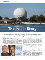
National Winner—Less than $15 Million<br />
LAMAR CORPORATE hEADqUARTERS – hUDSONVILLE, MICh.<br />
a<br />
construction company’s vision to place its corporate offices into a cantilevered<br />
space above warehouse and shop space challenged the design<br />
team to create a satisfying work environment in an unconventional structural<br />
context. as designers sought to realize the owner’s vision, guidelines were<br />
quickly established that would affect all aspects of the office design.<br />
Two 16-ft-deep, 112-ft-long cantilevered trusses were envisioned that would<br />
support the office from a vertical circulation shaft. These trusses would architecturally<br />
define perimeter office units as well as primary traffic aisles. Understanding<br />
pedestrian traffic was key to project success because the associated vibration<br />
would be the governing consideration in the truss design. This brought the truss<br />
design into the realm of predicting not only building use and performance, but<br />
the subjective responses of the office occupants.<br />
Early dynamic analysis suggested little difficulty with lateral and torsional motions,<br />
but vertical vibration presented some concern. The most reasonable truss<br />
designs would yield vertical mode vibration frequencies in a range approaching<br />
the frequency of rapid foot traffic. One solution would have been to add stiffness,<br />
but that also meant adding unwanted bulk to the members and connections,<br />
increasing both expense and visual obstructions.<br />
The team chose as an alternative to design somewhat above the walking frequencies<br />
while also making provisions to install tuned mass dampers (TmDs), but<br />
only if the occupants ultimately decided they were necessary. In principle, no one<br />
on the team favored TmDs as an initial design solution, but there were recognized<br />
benefits in making provisions for them as a backup system. This saved the owner<br />
from having to use massive trusses while still ensuring that a satisfactory workspace<br />
would be achieved.<br />
With this approach in mind, a preliminary design of TmDs was provided that<br />
promised to control uncomfortable vibration under worst-case projections. The<br />
office floor system was then designed to be framed with a pair of concealed<br />
chambers that would accommodate mounting TmDs to the bottom chords of the<br />
cantilever trusses.<br />
Extensive in-place testing performed both during and after construction to<br />
determine actual vibration characteristics confirmed that the structure is providing<br />
comfortable office use. The building opened in July 2007, and because the<br />
TmD installation has not been required, the floor chambers built to house them<br />
remain unused. Even so, those chambers ultimately served the project well by allowing<br />
the design team to confidently work beyond the range of experience and<br />
certainty to create a workspace of unprecedented character.<br />
The owner now enjoys a headquarters building that meets its functional needs,<br />
but also serves as a striking showcase of the firm’s skills as builders and innovators.<br />
Owner, <strong>Steel</strong> Erector and general Contractor<br />
Lamar <strong>Construction</strong> Company, Hudsonville, mich., (aISC and SEaa member)<br />
Architect<br />
Integrated architecture, Grand Rapids, mich.<br />
Structural Engineer<br />
Structural Design Inc., ann arbor, mich. (aISC member)<br />
<strong>Steel</strong> Detailer and Fabricator<br />
Van Dellen <strong>Steel</strong>, Dutton, mich. (aISC member)<br />
Consultant<br />
medhi Setareh, P.E., Ph.D., Virginia Tech, Blacksburg, Va. (aISC member)<br />
MODERN STEEL CONSTRUCTION may 2010<br />
Photos by Paul Dannels/Structural Design Inc.
“This is not a building you could drive by without<br />
taking a second (or third) look.<br />
”<br />
—Jennifer Richmond<br />
awards<br />
may 2010 MODERN STEEL CONSTRUCTION 24
awards<br />
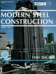
National Award—Less than $15 Million<br />
FIShERS ISLAND RESIDENCE – FIShERS ISLAND, N.y.<br />
Fishers Island sits at the eastern end of Long Island, N.y.,<br />
approximately two miles off the southeastern coast of<br />
Connecticut. The island is home to approximately 300<br />
permanent residents and a temporary population that grows to<br />
several thousand during summer weekends and holidays.<br />
The design of the Fishers Island Residence is a response to<br />
the unique island setting and the personal interests of the client<br />
and primary resident. The 4,600 sq. ft house was envisioned as a<br />
permanent retreat for a client wishing to integrate day-to-day life<br />
with a passion for gardening and love of modern art, furniture<br />
and architecture. The architects designed an unmistakably modern<br />
house, with an open floor plan, minimal aesthetics, abundant<br />
use of glass and exposed steel, and a modular discipline that<br />
is equally organic in its relation to the surrounding garden and<br />
landscape. The successful connection between nature and the<br />
man-made structure is realized through the creative and expressive<br />
use of architecturally exposed structural steel.<br />
The house is intended to simultaneously serve as a fullyfunctioning<br />
residence, a private museum for the owner to<br />
display a collection of art and furniture, and a permeable<br />
gateway into and through the surrounding garden. In an effort<br />
MODERN STEEL CONSTRUCTION may 2010<br />
to create this uninterrupted connection, the architect used<br />
high-performance, insulated floor-to-ceiling glazing on all four<br />
external walls of the house. To minimize visual interruption in<br />
the glazing, the structural engineer designed slender 2.75-in.<br />
square, solid steel columns supporting W10 primary beams<br />
that span 29 ft and W4, L3x3 and L5x5 secondary steel beams.<br />
The wide-flange steel roof framing supports a 1.5-in. wide, ribmetal<br />
roof deck. <strong>Steel</strong> framing was essential for maintaining<br />
uninterrupted windows and allowing shallow roof spans.<br />
The structural elements were carefully coordinated with the<br />
architectural expression, which greatly understates their relationship:<br />
the structural steel elements are the architecture. The<br />
exposed structural steel columns were engineered to be as<br />
small as structurally possible and designed to maintain a consistent,<br />
clean aesthetic throughout the house.<br />
The aesthetic treatment of structural steel is prominently<br />
displayed by the 50 steel “trees” every 11-ft, 6-in. around the<br />
house. Each tree consists of a solid 3.25 by 3.25 in. steel cantilevered<br />
column, rigidly fixed at the base. a steel casting at<br />
the top of the column is connected with a single, concealed,<br />
high-strength bolt. The casting spreads into four diagonal cast
Photos by Scott Frances<br />
“a very simple design<br />
that lends itself very well<br />
to its surroundings.<br />
“branch arms” at the top of each column that cantilever out<br />
approximately 8 ft from the columns.<br />
a trellis of solid aluminum rods is supported at the tips of<br />
each branch arm. a secondary system of trellis framing spans<br />
above the aluminum rods, cantilevering an additional 3 ft beyond<br />
the edge of the branch arms. This secondary system is<br />
supported by individual, high-strength rods attached to an<br />
innovative concealed “tongue plate” connection detail. The<br />
concealed tongue plate and rod connection allows the trellis<br />
to float above the branch arms with almost no visible means of<br />
support. an adjustable and fully concealed steel puck-like connection<br />
at the base of each support rod permits adjustment of<br />
the trellis-to-branch arm connections.<br />
The trellis, steel trees and branch arms are visually dramatic<br />
but also are essential to making the residence habitable. The<br />
canopies and trellis shield the full-height glass walls from direct<br />
overhead sunlight, dramatically reducing glare and light levels<br />
within the house. The steel trees also play an important role<br />
in the psychological transitioning between the outdoor natural<br />
realm, and the man-made environment of the interior.<br />
”<br />
—Brad Lange<br />
awards<br />
To provide the unique architecture of this residence, the architect<br />
and engineer worked closely to develop connections<br />
that were structurally robust and visually pleasing, avoiding<br />
conventional structural steel connections that would have ruined<br />
the visual appearance. The use of architecturally exposed<br />
steel castings celebrates steel connections as sculptural objects,<br />
but required intense coordination among the architect,<br />
engineer and fabricator. all steel elements were designed per<br />
code to resist the harsh 120 mph costal winds and significant<br />
ice and snow loads.<br />
Architect<br />
Thomas Phifer & Partners, New york<br />
Structural Engineer<br />
Skidmore, Owings & merrill, LLP, Chicago (aISC member)<br />
general Contractor<br />
BD Remodeling & Restoration, Fishers Island, N.y.<br />
may 2010 MODERN STEEL CONSTRUCTION
awards<br />
Merit Award—Less than $15 Million<br />
BURNhAM PAVILION – ChICAgO<br />
The Burnham Pavilion was one of two temporary pavilions<br />
constructed in Chicago’s millennium Park to celebrate<br />
the centennial of the Daniel Burnham and Edward Bennett<br />
Plan for Chicago. The project consisted of two large white<br />
planes, one of which served as an elevated walking surface,<br />
while the other was a widespread cantilevered roof. The two<br />
planes were joined by three large “scoops” that met with the<br />
roof to form openings in the roof plane, which frame predetermined<br />
views of the Chicago skyline.<br />
Both the upper and lower planes used W18 sections on an<br />
axis skewed from orthogonal to accommodate the three large<br />
scoop openings. Each scoop housed three 8-in. a53 Grade B<br />
pipes inclined at an average angle of 48° from vertical to fit within<br />
the envelope of the of scoop. The entire pavilion structure was<br />
framed with 49 tons of structural steel and infilled with plywood<br />
ribs, had a 45 ft, 6 in. by 52 ft, 6 in. footprint and a maximum<br />
“<br />
MODERN STEEL CONSTRUCTION may 2010<br />
It immediately strikes a chord<br />
with the viewer in the<br />
downtown park setting of Chicago.<br />
—Todd alwood<br />
Photos by George Lambros/Lambros Photography<br />
height of 19 ft, 6 in., with a total cost of roughly $1 million.<br />
To achieve the unique form of the pavilion, three main structural<br />
issues required resolution. The first was the design of the<br />
dramatic 23-ft, 6-in. cantilevers. The cantilevers had backspans<br />
that were limited by the scoop openings, which could not be<br />
penetrated. additionally, the roof was designed for a 90 mph<br />
wind load (20 psf, per the Chicago Building Code). an additional<br />
15 psf roof live load was checked despite the fact that the roof<br />
was not intended to be accessible. This check proved to be justified<br />
when groups of people were seen climbing up the scoops<br />
while watching Fourth of July fireworks displays from the roof of<br />
the pavilion.<br />
The second issue was that the curving form of the scoops<br />
did not allow for traditional vertical elements to support the roof<br />
structure, and thus a set of three sloping pipe columns was used<br />
in lieu of a vertical element. These three pipe columns all origi-<br />
”
awards<br />
MODERN STEEL CONSTRUCTION may 2010<br />
Photos by George Lambros/Lambros Photography<br />
nated at a single spring point at the base,<br />
then splayed upward to connect to the<br />
skewed roof framing. Naturally, the basepoints<br />
received a large vertical reaction<br />
from the roof, as well as a high bending<br />
moment induced by the severely sloped<br />
columns. This large reaction was too great<br />
to be carried by the precast double tees<br />
that frame over a multi-track commuter<br />
railway yard below, thus becoming the<br />
third major structural issue to develop.<br />
To solve this issue, a hexagonal steel<br />
grillage was provided directly below the<br />
spring point of the columns, rather than a<br />
direct support point. The grillage carried<br />
the load in bending across six horizontal<br />
“spokes” out to six support points, each<br />
of which saw a reaction small enough to<br />
be carried by the precast double tees.<br />
The analysis for the complex geometry<br />
was performed with finite element software<br />
using a linear elastic analysis.<br />
Coordination among design architects,<br />
architects of record, and the fabricator<br />
was vital to keep the steel structure within<br />
the envelope of the pavilion’s dually curving<br />
form. Due to the short time frame of<br />
the project, electronic 3D models had to<br />
be passed back and forth between offices<br />
with care and precision. Good communication<br />
among all parties and multiple<br />
software programs allowed detection of<br />
problem areas (cladding and structural<br />
interference) and ensured a smooth construction<br />
process.<br />
The UNStudio Burnham Pavilion was<br />
completed on schedule and within budget,<br />
and opened to the public June 19,<br />
2009.<br />
Owner<br />
Burnham Plan Centennial Committee,<br />
Chicago<br />
Architect<br />
UNStudio, amsterdam<br />
Associate Architect<br />
Garofalo architects Inc., Chicago<br />
Structural Engineer<br />
Rockey Structures, LLC, Oak Park, Ill.<br />
general Contractor<br />
Third Coast <strong>Construction</strong>, Chicago<br />
Consultant<br />
Dear Productions, Inc., Oak Park, Ill.<br />
Structural Analysis Software<br />
SaP2000
awards<br />
Merit Award—Less than $15 Million<br />
STORAgE BARN – WAShINgTON, CONN.<br />
MODERN STEEL CONSTRUCTION may 2010<br />
“This is a beautiful and elegant<br />
answer to the program. ”<br />
Photos by Bo Crockett/Gray Organschi architecture<br />
—mitchell Hirsch
For this structure, the architect envisioned a vertical and orderly<br />
method for storing landscape materials with minimal impact to the<br />
pondside site. The project design goals included electricity generation<br />
via a photovoltaic array on the roof, and a translucent skin to allow<br />
natural daylighting through the walls and roof. The 28 ft by 20 ft translucent<br />
structure also glows at night when interior lights are on.<br />
The daylighting is accomplished with translucent insulated polycarbonate<br />
panels on the walls and transparent photovoltaic panels on the<br />
roof set atop light cowls. The basement contains mechanical, electrical<br />
and plumbing equipment for the solar array and for a geothermal heating<br />
system. The garage stores the forklift and other equipment.<br />
as many as 114 custom steel pallets can be placed on the walls to hold<br />
stone tile, stone pavers, field stone, or firewood. The pallets reside on six<br />
tiers of steel brackets that cantilever from HSS steel columns.<br />
The foundation and ground floor of the enclosed structure are, respectively,<br />
conventional cast-in-place concrete walls and a concrete slab on<br />
metal deck. The large and variable pallet loads and their large eccentricities<br />
created significant building torsional and sway forces as well as significant<br />
out-of-plane bending forces. The forces are resisted by the floor,<br />
roof, and four walls all structurally integrated into a rigid six-sided box.<br />
The garage floor slab serves as the base of the box. The other five<br />
sides of the box are steel framed with moment frames along the four<br />
perimeter walls and a steel space frame roof. The moment frames are<br />
assembled from 16-ft-tall HSS6x6 columns and a wide-flange beam at<br />
the roof level. Diagonal braces were not used in the plane of the walls<br />
because they would obstruct the polycarbonate wall panels.<br />
The lack of columns in the wall containing the full width door resulted in<br />
insufficient in-plane stiffness. Rather than increase column and roof beam<br />
sizes to compensate, additional stiffness was provided with vertical trusses,<br />
one on each side of the building. The trusses allow the columns elsewhere<br />
to remain small and consistent in size. The horizontal members of the vertical<br />
trusses also perform as a bracket for the pallets at each tier.<br />
a designed and manufactured steel space frame was selected for the<br />
roof framing to satisfy three criteria. First, an eye-pleasing roof system was<br />
desired because it would be exposed to view. Second, in-plane strength<br />
and stiffness were necessary to resolve the building torsional forces and<br />
sway forces. and third, it does not obstruct light transmitting through the<br />
translucent roof surface.<br />
The space frame was assembled on the ground into two pieces and then<br />
bolted to the perimeter roof beams to complete the rigid six-sided box. all<br />
structural steel was hot dipped galvanized. Slender steel outriggers were<br />
bolted to the top of the first bay along the perimeter of the space frame to<br />
support the very thin wood framed roof overhang. Wood 2x nailers were<br />
bolted to the top of the space frame at the nodes to fasten the plywood<br />
roof sheathing and the wood cowls that support the photovoltaic panels.<br />
With 114 pallets, each potentially supporting stone material, there is<br />
seemingly an infinite number of possible pallet load arrangements to consider.<br />
Unbalanced loading can result in unusually large sway forces and large<br />
building torsional forces. The many possible pallet load arrangements were<br />
distilled down to those that would maximize building sway and torsion:<br />
• A full complement of fully loaded pallets<br />
• Load combinations with and without wind forces and snow loads<br />
• An impact load due to the forklift dropping and lifting pallets<br />
a 3D analysis model was created to test the strength and performance<br />
of the steel framed superstructure due to the various load combinations.<br />
The space frame roof was modeled as a rigid diaphragm with rigid links<br />
where it engages the roof beams. Then the output shear forces in the<br />
rigid links were transmitted to the space frame manufacturer for each load<br />
case use in designing the space frame and its connections.<br />
The structural system derives its success from the use of simple components<br />
and its careful integration with the architectural design.<br />
awards<br />
Architect<br />
Gray Organschi architecture, New Haven, Conn.<br />
Structural Engineer<br />
Edward Stanley Engineers, LLC, Guilford, Conn.<br />
(aISC member)<br />
Fabricator<br />
Southington metal Fabrications, Southington,<br />
Conn. (aISC member)<br />
general Contractor<br />
Catalpa management, morris, Conn.<br />
Structural Analysis Software<br />
RISa-3D, Revit<br />
may 2010 MODERN STEEL CONSTRUCTION
awards<br />
National Award—$15 Million to $75 Million<br />
CONTEMPORARy JEWISh MUSEUM – SAN FRANCISCO<br />
The recently completed Contemporary Jewish museum is<br />
one of the last pieces in the revitalization and transformation<br />
of the once decaying yerba Buena district in downtown<br />
San Francisco. The bold and striking new 63,000-sq.-ft,<br />
$47.5 million museum building beautifully integrates modern<br />
materials and complex forms with the old Jesse Street Power<br />
Station, a national historic landmark designed by Willis Polk in<br />
1907 during the “City Beautiful” movement. The historic features<br />
of the landmark substation, most notably its ornate brick<br />
and terra-cotta façade, steel trusses, crane and catwalk, were<br />
integrated into the building’s structure.<br />
The building’s contemporary form was inspired by the Hebrew<br />
phrase l’chaim (to life!), which led to highly complex geometry<br />
and a very irregular structure. Given the complicated<br />
geometry, structural steel was the most appropriate and costeffective<br />
framing system for the building.<br />
The building is located in an area of high seismic activity.<br />
Resistance to earthquake loads is provided by steel braced<br />
frames. although essentially a two-level structure, the highest<br />
point in this angular building rises almost 70 ft above the<br />
ground level. The complex geometry of the building blurs the<br />
“ Tons of curb appeal.<br />
”<br />
—Tudor Van Hampton<br />
MODERN STEEL CONSTRUCTION may 2010<br />
lines between beams and columns, and which elements are resisting<br />
gravity loads and which are resisting lateral loads. many<br />
columns are not vertical—some lean in two directions—and<br />
the braced frames carry not only the earthquake loads but also<br />
gravity loads.<br />
Structural engineers built a 3D computer model of the building<br />
in order to perform detailed response spectrum dynamic<br />
analyses. Because the braced frames also carry gravity loads,<br />
seismic design is required to ensure nearly-elastic behavior for<br />
the maximum credible earthquake.<br />
Designing and detailing the complex geometry posed a significant<br />
challenge, especially regarding connections. at numerous<br />
locations, as many as eight steel members come together<br />
at different angles and in different planes, requiring creativity<br />
and imagination in designing and drawing up the connections.<br />
Engineers drew as many as four views of key connections to<br />
convey the intent of the design. Because there was such large<br />
risk for unresolved issues and multiple change orders if the<br />
project had been bid and constructed using only 2D drawings,<br />
the details ultimately were drawn in 3D.<br />
To overcome those concerns, the engineer recommended
that the client retain the services of a steel detailer, Dowco Consultants,<br />
Vancouver, B.C., to develop a 3D model of the structure<br />
as the design proceeded. This approach, a precursor to current<br />
BIm practice, led to a highly interactive design process.<br />
The engineer provided autoCaD files of design drawings to<br />
Dowco as they were developed. Dowco used that information to<br />
prepare its 3D model and sent that information back to the engineer<br />
for review and updating its drawings. Using this process<br />
enabled the team to identify and resolve a host of conflicts and<br />
potential problems. making the model available to steel bidders<br />
led to reduced uncertainties, and, consequently, tighter bids.<br />
The general contractor and the steel detailing, fabrication<br />
and erection team were brought on board early in the design<br />
phase, allowing for creative and practical solutions and close<br />
collaboration. That led to a project that was successfully completed<br />
within time and budget with only minor changes. The<br />
museum opened to wide acclaim in June 2008.<br />
OLmm was awarded the 2009 Outstanding Structural Engineering<br />
Project award for the California region by aSCE for<br />
this project.<br />
Owner<br />
Contemporary Jewish museum – San Francisco<br />
Architect<br />
Studio Daniel Libeskind, New york<br />
Associate Architect<br />
WRNS Studio, San Francisco<br />
Structural Engineer<br />
OLmm Consulting Engineers, Oakland, Calif.<br />
<strong>Steel</strong> Erector<br />
Olson <strong>Steel</strong>, San Leandro, Calif. (ImPaCT member)<br />
general Contractor<br />
Plant <strong>Construction</strong> Co., San Francisco<br />
Consultant<br />
aRUP, San Francisco (aISC member)<br />
Structural Analysis Software<br />
SaP2000, TEKLa Structures<br />
awards<br />
may 2010 MODERN STEEL CONSTRUCTION
awards<br />
National Award—$15 Million to $75 Million<br />
DEE AND ChARLES WyLy ThEATRE – DALLAS<br />
The Dee and Charles Wyly Theatre features an unprecedented<br />
vertical organization that completely<br />
rethinks the traditional approach to theater design.<br />
For centuries, traditional theaters have been horizontally<br />
oriented around the performance chamber, with “front<br />
of house” and “back of house” areas flanking either side<br />
and a fly tower above.<br />
The Wyly architecture team instead envisioned a transparent<br />
four-sided performance zone at ground level that<br />
would blur the lines between inside and out, actor and<br />
observer, in a literal interpretation of the world as a stage.<br />
To create this vision on a small site within a tight budget,<br />
the architectural and structural teams pulled apart each individual<br />
theater program element; carefully examined usage,<br />
size, and adjacency requirements; then reassembled<br />
the pieces into an intricate vertical structural stack, with<br />
“back of house” becoming “above house” and “front of<br />
house” (including the lobby) becoming “below house.”<br />
This vertical rearrangement produced the desired 27-fthigh,<br />
fully transparent, structure-free, four-sided, groundlevel<br />
performance zone, but demanded the invention of a<br />
one-of-a-kind structural steel system.<br />
To create the most flexible performance space ever,<br />
the building itself had to be able to move, adapt, and<br />
evolve. Through the application of advanced technologies—both<br />
newly developed and borrowed from other<br />
industries—the Wyly is a miracle of moving steel parts,<br />
driven by engineering innovation. The audience chamber<br />
moves up, down, in, and out to create an unlimited<br />
number of performance configurations: proscenium,<br />
thrust, arena, traverse, studio theater, flat floor, bipolar,<br />
and sandwich have been identified so far.<br />
The 27-ft-high proscenium arch—unmovable in most<br />
theaters—retracts straight up into an enlarged “super-fly”<br />
area. Three-tiered steel balcony units—the largest weighing<br />
120 tons—also move up and down, adding 180 additional<br />
seats upon demand then “disappearing” when not needed.<br />
The balcony units lower from/lift into the super-fly area,<br />
can adjust horizontally up to 6 ft based on stage configuration,<br />
and carry their own drawbridge floor and access stair<br />
units. a combination of moveable seating wagons and nine<br />
moveable platforms rise, fall, and rotate to accommodate<br />
stage arrangement or produce a totally flat, open floor. The<br />
orchestra pit rises and retracts below the performance floor<br />
into the three-level below-house area. Even the walls move,<br />
with two 10-ft-wide floor-to-ceiling glass panels pivoting to<br />
the outside. The resulting “building machine” offers complete<br />
reconfigurability and true performance freedom. No<br />
other venue in the world can host an open-to-the-outdoors,<br />
flat-floor event in the afternoon, and an intimate stage performance<br />
only hours later.<br />
Looking at the structural frame developed for the<br />
Wyly, it is clear that a traditional structural system could<br />
not have met the project’s unique and complex program<br />
goals. The requirements were strict: No structure could<br />
be inserted in the 90-ft by 90-ft ground-floor performance<br />
area; no structure could interfere with the negotiated<br />
above-house program areas; and only a minimal amount<br />
MODERN STEEL CONSTRUCTION may 2010<br />
Photo by Theo Raijmakers<br />
“a great demonstration of what<br />
a steel frame can do that no<br />
other material could accomplish.<br />
—Jack Petersen<br />
of structure could interrupt the ground-level transparency zone.<br />
The answer, pure but complex, is a unique “global frame” consisting<br />
of six perimeter columns, four of which incline dramatically and<br />
asymmetrically to touch down in precisely predetermined locations.<br />
a three-story-high steel belt truss augmented by smaller interior steel<br />
trusses fill out the global frame, minimizing vertical height while supporting<br />
a puzzle-piece assemblage of rooms so complex and interlocking<br />
that only one floor at the top of the belt truss is contiguous.<br />
The vertical positioning of the belt truss optimizes the strength of that<br />
one contiguous floor, while intricate positioning of the belt truss/sloped<br />
column intersections supports 44-ft corner cantilevers and 90-ft clear<br />
spans at ground level, preserving views and column-free performance<br />
areas. Opposing building forces are addressed using strategic inclines<br />
rather than traditional (and intrusive) vertical braced elements, with dualduty<br />
columns resisting gravity and wind loads. This minimalist yet highly<br />
effective structural solution produces a ground-floor performance area<br />
”
awards<br />
with no interior columns and accomplishes the architect’s goal of<br />
blurring the lines between audience and stage.<br />
The steel belt truss encompassing Levels 4 through 7 supports<br />
loads so heavy that each of the building’s four truss faces relies on<br />
the connectivity and continuity of the other three faces for stability.<br />
In other words, no single truss face is stable on its own. as a result,<br />
complex construction sequencing analyses were used to determine<br />
the ideal erection sequence. Ultimately, six temporary erection<br />
columns supported the truss until the four truss faces were<br />
joined and successfully functioning as a cohesive 3D unit.<br />
Owner<br />
aT&T Performing arts Center, Dallas<br />
Architect of Record<br />
Kendall/Heaton associates, Houston<br />
MODERN STEEL CONSTRUCTION may 2010<br />
Photo by Theo Raijmakers<br />
Photo by Iwan Baan Photography<br />
Design Architect<br />
REX/Oma, New york<br />
Structural Engineer<br />
magnusson Klemencic associates, Seattle (aISC member)<br />
<strong>Steel</strong> Fabricator<br />
W&W <strong>Steel</strong>, Oklahoma City (aISC member)<br />
<strong>Steel</strong> Erector<br />
Bosworth <strong>Steel</strong> Erectors, Dallas (aISC, TaUC, and SEaa<br />
member)<br />
general Contractor<br />
mcCarthy, Dallas<br />
Consultant<br />
KFC Engineering, Oklahoma City
awards<br />
National Award—$15 Million to $75 Million<br />
ARkANSAS STUDIES INSTITUTE – LITTLE ROCk, ARk.<br />
The arkansas Studies Institute, a unique partnership between<br />
a metropolitan library and a state university, is a<br />
repository for 10 million historic documents and the papers<br />
of seven arkansas governors, including President William<br />
Jefferson Clinton.<br />
Located in a thriving entertainment district near the Clinton<br />
Presidential Library, the design combines significant but<br />
neglected buildings from the 1880s (heavy timber) and 1910s<br />
(concrete) with a new technologically expressive steel archive<br />
addition, creating a pedestrian focused, iconic gateway to the<br />
public library campus and the face of arkansas history. Public<br />
spaces—galleries, a café, and a museum—enliven streetscape<br />
storefronts, while a great research hall encompasses the entire<br />
second floor of the 1914 building.<br />
Because the existing structures could not support the weight<br />
capacity needed for the archive collection, a new addition on<br />
a 50-ft-wide lot previously used for parking was planned to<br />
house three full floors of compact shelving above an open,<br />
glass-wrapped “soft story” gallery at street level. <strong>Steel</strong> was the<br />
obvious choice because it provided the required free spans and<br />
offered architecturally expressive truss options for the interior<br />
gallery. The juxtaposition of heavy document storage above<br />
light, open galleries creates an instantly identifiable image for<br />
the arkansas Studies Institute.<br />
In formulating the structural concept, designers studied how<br />
the existing buildings’ structures were left exposed, expressing<br />
the construction methods of the different centuries in which<br />
each was built. The beauty of these structures is in the simple<br />
MODERN STEEL CONSTRUCTION may 2010<br />
elegance of constructing just what is needed, meaning that all<br />
structural systems for this building should be celebrated as part<br />
of telling an honest story—the story of the state’s construction<br />
history. The goal was set to minimize applied ornamentation<br />
normally found in a library building, and instead to show the<br />
functional detailing of the steel in a beautiful way.<br />
The design philosophy is based literally on the book—a<br />
physical container of information, with pages flowing into a sitesensitive,<br />
physical narrative of the building’s function. multiple<br />
curving glass walls hang lightly off of the wide-flange and HSS<br />
frame of the new addition’s main façade, representing pages of<br />
an open book where patrons literally walk through the pages of<br />
history, from new to historic spaces.<br />
Between buildings, a thin atrium pulls the new steel structure<br />
away to protect the old, stretching the building’s length and<br />
flooding all levels with light—a key sustainable strategy. Suspended<br />
bridges span the gap between new and old, connecting<br />
architectural centuries. This four-story atrium acts as a vertical<br />
gallery to tell the state’s story. <strong>Steel</strong>-framed handrails mimic<br />
filmstrips through the height of the space, providing locations<br />
for 100 historic images from the archives in glass panels.<br />
The steel bridges are suspended from a trussed interior frame,<br />
hinged at the base in a drawbridge-like fashion, and incorporate<br />
wood bridge decks recycled from a bridge in the present<br />
governor’s hometown. Document storage displayed through the<br />
atrium’s glass walls expresses that knowledge is within reach.<br />
To avoid a true atrium designation, a concealed steel fire<br />
shutter divides the space into two vertical zones, which is a
“<br />
The exposed steel in this building is a great example<br />
of how structural steel can be used as an aesthetic feature.<br />
unique and less costly solution that allowed the structural steel<br />
to be left exposed. The expressive bridge-like frame of the new<br />
archive’s structure acts as the lateral bracing for the building.<br />
The structure was not only left exposed, but the steel deck was<br />
left unpainted. Light testing proved this solution equal to paint,<br />
and much more honest—raw history on display.<br />
The curving west structure bends back to miss the site’s only<br />
mature tree, while creating a reading lawn at the gallery steps,<br />
achieving a symbiotic relationship between the man-made and<br />
nature. The new addition’s structure is actually on the outside<br />
of the building façade. This creates an expressive grid that acts<br />
as a shaded porch, inviting all at the main pedestrian street to<br />
be drawn into the new gallery, as well as around the corner to<br />
the main library entrance on the next block. Extended steel<br />
beams at western and southern floor edges are capped with<br />
galvanized steel grates to expand sun protection and lighten<br />
the edges. The west façade’s pin-mounted vertical frosted<br />
glass fins control sun exposure while displaying historic faces of<br />
arkansas life, like large bookmarks in time.<br />
The copper-clad steel entrance idea came during project<br />
research, as the designer was using an old worn leather book,<br />
studying not only the content but the way the book moved as<br />
the pages turned. Taking cues from this written medium, the<br />
copper entrance acts as an abstract book cover, pulled away<br />
from the building as a double wall, diffusing the setting sun’s<br />
light and heat in the entrance atrium beyond. and like a leather<br />
book cover, with its binding exposed to the intersection, the<br />
copper will age over time.<br />
photos by Timothy Hursley<br />
—Brad Lange<br />
awards<br />
Locally sourced materials tell the story of the state’s industries,<br />
exceeding sustainable requirements for distance to site and recycled<br />
content. The steel structure offered manufacturing within<br />
the state and 97% recycled content, adding to the fact that steel is<br />
the dominate construction material of our time and place. aluminum<br />
curtain wall and skin, making up over 90% of the exterior, was<br />
fabricated just blocks away at a major glazing company.<br />
The arkansas Studies Institute weaves history, research, the citizenry,<br />
and a restored streetscape together, healing a gaping wound<br />
in the urban fabric, while serving as a beacon of knowledge.<br />
Owner<br />
Central arkansas Library System, Little Rock, ark.<br />
Architect<br />
Polk Stanley Wilcox architects, Little Rock, ark.<br />
Structural Engineer<br />
Kenneth Jones and associates, Inc., Little Rock, ark. (aISC<br />
member)<br />
general Contractor<br />
East Harding, Inc., Little Rock, ark.<br />
”<br />
may 2010 MODERN STEEL CONSTRUCTION
awards<br />
National Award—greater than $75 Million<br />
LINCOLN CENTER JUILLIARD SChOOL, ALICE TULLy hALL – NEW yORk<br />
The transformation of the Juilliard<br />
School and alice Tully Hall opens<br />
the existing building to the neighborhood<br />
making it more accessible to the<br />
public. The project adds approximately<br />
150,000 sq. ft of new space, and at the<br />
same time upgrades interior finishes,<br />
building services and life safety systems<br />
MODERN STEEL CONSTRUCTION may 2010<br />
“Simple and elegant<br />
the heart of downtown NyC.<br />
—Todd alwood<br />
”<br />
in the existing building.<br />
all of the construction work on this project<br />
had to be coordinated with the ongoing<br />
operation of the school, activities on<br />
the campus, and performance and event<br />
schedules for alice Tully Hall, which was<br />
dark for only one season. During the five<br />
years of design and construction, the proj-<br />
ect team created and coordinated multiple<br />
packages of documents corresponding to<br />
the logistical challenges and sequencing of<br />
the work. Temporary spaces were created<br />
to replace functions impacted by construction.<br />
<strong>Construction</strong> managers, design team<br />
and owner’s project managers exercised a<br />
high level of oversight during construction<br />
to minimize conflicts and mitigate unforeseen<br />
field conditions.<br />
This challenge was magnified by a<br />
desire for the highest quality levels in<br />
selection of materials and craftsmanship.<br />
most of the interior finishes and exterior<br />
curtain walls are one-of-a-kind systems,<br />
specifically created for this project. The<br />
interior wall panels of alice Tully Hall are<br />
a unique laminate of super thin wood veneer<br />
on resin panels. The eastern façade<br />
of the Juilliard School is a highly customized,<br />
highly translucent glass wall to open<br />
the building to the public.<br />
Complex structural elements, duct runs,<br />
curtain walls and wall panels were designed<br />
and built using 3D modeling technologies,<br />
which the engineers and architects also<br />
used for interdisciplinary coordination.<br />
The structure of alice Tully Hall uses<br />
a smart, cost efficient partial-box-in-box<br />
construction in combination with rail isolation<br />
on the subway lines to isolate the<br />
hall from the vibrations of the 7th avenue<br />
Subway. In addition, new HVaC systems<br />
lower the background noise imposed on<br />
the space. a new high-performance inner<br />
liner is acoustically engineered to distribute<br />
sound evenly throughout the house.<br />
Thin layers of moabe veneer laminated to<br />
three-dimensionally curved resin panels<br />
are tailored around all existing hall features,<br />
eliminating “visual noise” that distracts the<br />
audience from the performance.<br />
The improved facilities will allow Lincoln<br />
Center to continue its tradition in<br />
offering world-class performances and<br />
education to local, national and international<br />
audiences. With its innovative use<br />
of new materials, unique space generating<br />
structure, interface of new and old,<br />
logistical and schedule challenges, the<br />
project pushed New york’s design and<br />
contractor community to the boundaries<br />
of construction technologies and what<br />
could be built, setting a new standard for<br />
future buildings to come in this city.<br />
The expansion of the Juilliard School of<br />
music above alice Tully Hall is facilitated<br />
by a number of parallel, west-east running,<br />
story-high, steel mega-trusses, which can-
tilever over a new public plaza and create<br />
a unique architectural space. The megatrusses<br />
are made up of W14 sections<br />
weighing up to 398 lb/ft. In a complex layering<br />
of additional secondary trusses and<br />
tertiary beams floor plates are made up of<br />
concrete on metal decking and built up or<br />
hung down from the mega-trusses.<br />
The mega-trusses have a cantilever to<br />
backspan ratio of 3 to 2 and a structural<br />
depth of 13 ft, 5 in. The backspan is socketed<br />
into the existing columns of the existing<br />
building. Existing columns and footings<br />
required reinforcement to allow for<br />
additional load imposed by the expansion.<br />
The columns on the other support points<br />
for the trusses define the exterior envelope<br />
of the new lobby. a new single layer, flat<br />
cable curtain wall separates the new lobby<br />
from the exterior plaza. The cable net imposes<br />
large tensile forces onto the steel<br />
structure and onto the foundations to limit<br />
deflections for the glass panels.<br />
The mega-trusses were prefabricated<br />
by the steel supplier and feature stiffened,<br />
welded connections at each of the<br />
truss node points. The welded connections,<br />
which are free of gusset plates, allow<br />
for the passage of the building services<br />
systems. Top and bottom chords<br />
were spliced at quarter points, diagonals<br />
are spliced at their mid points, allowing<br />
for the assembly of the trusses on site.<br />
<strong>Construction</strong> started in spring of 2007<br />
and lasted through February 2009. The<br />
project opened on schedule in February<br />
2009 earning unique critical acclaim in the<br />
press and in the construction industry.<br />
Owner<br />
Lincoln Center Development Project,<br />
New york<br />
Architect<br />
Diller Scofidio + Renfro, New york<br />
Associate Architect<br />
FXFowle, New york<br />
Structural Engineer<br />
aRUP, New york (aISC member)<br />
general Contractor<br />
Turner <strong>Construction</strong> Company, New york<br />
(ImPaCT member)<br />
awards<br />
Photos by Iwan Baan/ Iwan Baan Photography<br />
may 2010 MODERN STEEL CONSTRUCTION 38
awards<br />
National Award—greater than $75 Million<br />
BANk OF AMERICA TOWER AT BRyANT PARk–<br />
NEW yORk<br />
Rising a majestic 1,200 ft above the streets below,<br />
the Bank of america Tower at One Bryant Park<br />
joins the ranks of New york City’s architectural<br />
masterpieces. Owned jointly by The Durst Organization<br />
and Bank of america, this building showcases the results<br />
of innovative architectural and engineering design,<br />
which facilitated the creation of the tower’s magnificent<br />
crystalline shape.<br />
The beauty of the tower, however, is only one of its<br />
contributions to the city. Perhaps even more important,<br />
this new tower likely will become the first high-rise<br />
building in the world to earn a platinum LEED certification<br />
from the U.S. Green Building Council. To earn this<br />
notable designation, building designers incorporated<br />
not only green construction practices but also an array<br />
of sustainable technologies, such as a graywater collection<br />
system, thermal storage and a cogeneration power<br />
plant, enabling it to consume less water and use less<br />
energy than a conventional office tower.<br />
The building was constructed using approximately<br />
25,000 tons of structural steel—with a recycled content<br />
of at least 75%—and 45% granulated blast furnace slag<br />
(GBFS) substituted for cement in the concrete. The design<br />
also specified many recycled and local materials,<br />
avoided materials with volatile organic compounds, and<br />
minimized the generation of construction debris.<br />
a project of this magnitude required collaboration<br />
among all parties. Coordinating the work of numerous<br />
firms is difficult under the best of circumstances, but the<br />
project’s location less than a block from Times Square,<br />
in the center of midtown manhattan, made the process<br />
substantially more challenging.<br />
The building includes 2.1 million sq. ft of office and<br />
trading space spread over 51 occupied floors. There<br />
are three expansive cellars beneath the building—the<br />
deepest is 60 ft below ground level—and four mechanical<br />
floors at the top. The peak of the angled screen wall<br />
reaches a height of 945 ft while the 300-ft architectural<br />
spire tops out at 1,200 ft above the sidewalk. at a point<br />
about one third of the way up, the corners of the building<br />
start to taper gradually inward, giving the building<br />
its distinctive appearance.<br />
Because steel erection was scheduled to precede<br />
placement of the core walls, the core framing was designed<br />
as a temporary structure, which only had to support<br />
12 floors of its own weight before being encased in<br />
concrete. The core itself was framed with columns and<br />
beams, just as it would be for a conventional steel building,<br />
but the framing was much lighter. To accommodate<br />
the outer elements of the self-climbing formwork system,<br />
temporary slots were framed in the structural steel<br />
surrounding the core.<br />
Cantilevered screen walls that extend up to 60 ft<br />
above the roof preserve the little space left at the top of<br />
the building for mechanical equipment. The supporting<br />
structural steel, which is visible from outside the building,<br />
was given a clean, simple look by using bolted sleeve<br />
MODERN STEEL CONSTRUCTION may 2010<br />
“<br />
It is a distinctive piece of<br />
architecture while still working<br />
toward sustainability.<br />
—Jack Petersen<br />
”
awards<br />
Photos by Ray Jackson/Bernstein associates<br />
connections. The larger tubes fit snugly over the smaller tubes and give<br />
the joints the appearance of being fully welded. The purely aesthetic architectural<br />
spire continues the taper of the faceted walls to a single point<br />
at its tip. although originally envisioned as a single lattice of welded<br />
steel pipes, the spire was fabricated in a series of shop-welded subassemblies<br />
that were bolted together in place.<br />
as a New york City landmark, the 80-ft-wide, 50-ft-high brick and<br />
terra cotta façade of the historic Henry miller’s Theater had to be preserved.<br />
The interior of the theater, however, was not protected, which<br />
meant that it could be demolished and reconstructed. Before demolition<br />
could begin, though, the façade was stabilized by using an external<br />
steel framework that cantilevered from the sidewalk. The façade<br />
occurs at the deepest portion of the building’s foundation, so careful<br />
underpinning and a rock shelf were used to support it.<br />
Reconstruction of the theater posed challenges as well. The auditorium<br />
size and location required the transfer of several of the podium<br />
columns. To eliminate the need for shoring and reduce overall erection<br />
time, steel plate girders instead of trusses were used to make the transfer.<br />
One-piece plate girders would have been too heavy and too deep<br />
to lift over the existing façade so each plate girder was built up from<br />
three 7-ft-deep full-length sections. making that substitution allowed<br />
steel erection over the theater to proceed without an interruption to<br />
install temporary supports. at the exterior of the building, using a steel<br />
vierendeel truss minimized obstruction of the view from the windows.<br />
Double lines of steel framing and columns located on the sides and<br />
back of the auditorium create a 4-in.-wide joint to acoustically isolate<br />
the theater from the building that surrounds it. Independent bracing<br />
on the east and west sides of the auditorium resists lateral loads longitudinally.<br />
Transversely, bearing pads bridge the joint—with no significant<br />
loss of acoustic isolation—to transfer lateral loads to the building’s<br />
diaphragms and shear walls.<br />
In addition to their functional requirements, the owners desired a<br />
building that would reflect and embody the principles of sustainable<br />
development and yet still be economical to construct and operate.<br />
many systems and strategies were considered but only approaches<br />
that represented a reasonable return on investment were pursued and<br />
implemented. although adding green technologies and construction<br />
practices marginally increased the project budget, the expected savings<br />
in energy and water will continue to benefit the environment long<br />
after the additional initial construction costs have been offset.<br />
Owner<br />
The Durst Organization, New york<br />
Architect<br />
Cook+Fox architects LLP, New york<br />
Associate Architect<br />
adamson associates architects, Toronto<br />
Structural Engineer<br />
Severud associates, New york (aISC member)<br />
<strong>Steel</strong> Detailer and Fabricator<br />
Owen <strong>Steel</strong> Company, Inc. Columbia, S.C. (aISC and SEaa member)<br />
<strong>Steel</strong> Erector<br />
Cornell and Company, Inc., Westville, N.J. (aISC and ImPaCT<br />
member)<br />
general Contractor<br />
Tishman <strong>Construction</strong> Corp., New york (aISC member)<br />
Consultant<br />
Jaros Baum & Bolles, New york
awards<br />
Merit Award—greater than $75 Million<br />
CRySTALS AT CITyCENTER – LAS VEgAS<br />
Crystals is the centerpiece of CityCenter, an $8.5-billion<br />
Las Vegas urban development retail and entertainment<br />
district designed by eight renowned architects. The<br />
665,000-sq.-ft facility includes a below-grade garage, two levels<br />
of retail and a one-of-a-kind roof, which is the most complex<br />
and unique design within CityCenter.<br />
The roof actually consists of 19 separate pieces—13 planar<br />
roofs and six dramatically sloped arcade roofs—each erected<br />
with numerous leaning columns, curving trusses and straight<br />
members that do not line up with any other piece of steel. The<br />
six arcade roofs were the most complex element of Crystals.<br />
Crystals’ roof has no right angles, does not follow a pattern<br />
or have any repetitive placements of steel. all of the six arcade<br />
roofs are designed at different angles to connect with the 13<br />
planar roofs. The six arcade roofs converge at the apex of the<br />
facility with the planar roofs on the side. The arcade roofs are<br />
covered in glass to create a massive skylight to illuminate the<br />
building’s interior, hence the name Crystals.<br />
The challenge for the design-assist team was to figure out<br />
how to build this complex facility on schedule and budget. The<br />
design-assist portion of the project alone took 12 months of<br />
MODERN STEEL CONSTRUCTION may 2010<br />
working through mathematical equations and strategic planning<br />
to devise a 3D model, which ended up including 16,455 pieces.<br />
While the connections of the lower floors were standard, the<br />
roof system required distinctive solutions at almost every end<br />
point. more than 500 unique sketches were generated for the<br />
roof connections, each of which had to be manually modeled,<br />
as no single macro could accommodate these variations.<br />
more than 90% of the 52,766 steel connections are bolted.<br />
Some trusses and columns have as many as 15 connections. When<br />
bolting was not an option, joints were welded on site. The banana<br />
truss, which measures 6 ft deep and almost 200 ft long, slopes to<br />
the apex of the facility and was among the most critical welding<br />
tasks on the entire project. Crews hung the banana truss with two<br />
cranes while they welded it in three different places.<br />
Three-dimensional modeling was paramount to the project,<br />
including creation of BIm models for various trades and consultants.<br />
Without the software, constructing Crystals would not<br />
have been possible; manually drawing the extremely complex<br />
geometry would have been cost-prohibitive. Using a 3D system,<br />
however, there were almost no detailing-related errors.<br />
CityCenter’s master plan dictated that construction begin at
Photo by Schuff <strong>Steel</strong> Company<br />
“<br />
This design shows that,<br />
when using steel,<br />
the only limit to what can be created<br />
is the imagination.<br />
Photo by mGm mirage<br />
”<br />
—Jennifer Richmond<br />
the west side of the project and work toward Las Vegas Boulevard.<br />
That meant erection started at the highest point of the<br />
roof, but had to strategically “jump” around to ensure stability<br />
of all the leaning trusses and columns.<br />
The team first determined where each of the 80 major trusses<br />
went and from there worked backward to resolve what each<br />
truss would support, and what would support it. With thousands<br />
of massive beams, 160 trusses and 69 pipe columns literally<br />
cutting through one another and leaning at extreme angles—<br />
as much as 40°—every piece of steel required calculations to<br />
test for load capacity, fabrication and constructability.<br />
The fabricator used 14 fabrication shops to meet the Crystals’<br />
accelerated deadline. Fabrication started in January 2006<br />
and was completed in march 2008 for the base contract. Over<br />
that two-year period, 1,433 trucks were required to deliver the<br />
13,900 tons of structural steel. The result is a stunning structure<br />
that also is Gold LEED certified by the USGBC.<br />
Owner<br />
mGm mirage, Las Vegas<br />
awards<br />
Photo by Schuff <strong>Steel</strong> Company<br />
Architect<br />
Studio Daniel Libeskind, New york<br />
Associate Architect – Architect of Record<br />
adamson associates, Toronto<br />
Structural Engineer<br />
Halcrow yolles, Las Vegas (aISC member)<br />
<strong>Steel</strong> Detailer<br />
BDS <strong>Steel</strong> Detailers, Tempe, ariz./South Brisbane, australia<br />
(aISC member)<br />
<strong>Steel</strong> Fabricator and Erector<br />
Schuff <strong>Steel</strong> Co., Phoenix (aISC, ImPaCT, and SEaa member)<br />
general Contractor<br />
Perini Building Co., Henderson, Nev. (aISC member)<br />
Consultant<br />
Gensler – architect of Record, Las Vegas<br />
Structural Software<br />
Tekla Structures, Revit, autoCaD<br />
may 2010 MODERN STEEL CONSTRUCTION
“<br />
awards<br />
a project such as this allows the industry<br />
to move from research to practice.<br />
President’s Award of Excellence in Engineering<br />
L.A. LIVE – LOS ANgELES<br />
MODERN STEEL CONSTRUCTION may 2010<br />
Photo by Nabih youssef associates<br />
”<br />
—Jack Petersen<br />
The Los angeles Convention Center<br />
Hotel and Condominium (LaCCH)<br />
tower encompasses more than 1.2<br />
million sq. ft of floor space comprising a<br />
26-story low-rise portion combined with<br />
a 55-story portion that reaches more than<br />
650 ft above street level. The project carried<br />
a $1 billion development cost, and<br />
is the focal point of a large integrated<br />
development stretching across two city<br />
blocks.<br />
The tower is composed of 26 floors of<br />
hotel rooms in each of the wings, topped<br />
by 29 additional levels of condominiums<br />
in the taller tower. The tower includes a<br />
tapered floor plate that expands and contracts<br />
to suit the requirements of the occupancy<br />
type. The design features high ceilings<br />
with low floor-to-floor heights while<br />
minimizing the curtain wall, and maximizes<br />
sellable floor space by minimizing circulation<br />
paths and back-of-house spaces.<br />
The structural system is an optimized<br />
direct fit into the architectural shape, maximizing<br />
program efficiency and seismic<br />
performance. The system consists of unstiffened<br />
thin steel plate walls ( 3 ⁄8-in. to ¼-in.<br />
thick) within fully welded WUF-W moment<br />
frames that act as boundary members.<br />
The walls consist of infill plates that<br />
buckle in shear and form a diagonal tension<br />
field to resist lateral loads, resulting<br />
in substantial post-buckling ductility. as<br />
there was no centralized core of walls<br />
and the floorplan for the lower 26 stories<br />
formed a “T” shape, the steel plates<br />
were used to “tune” the stiffness of the<br />
separate wings.<br />
The boundary element frames included<br />
composite concrete-filled box<br />
columns in order to achieve a higher axial<br />
capacity at minimal premium. Where<br />
possible, the steel columns on the tower<br />
exterior slope from one floor to the next<br />
to match the architectural profiles and<br />
maintain a constant slab edge distance<br />
while minimizing disruption to useable<br />
floor space.
Outriggers at mid-height and the roof level further control<br />
building drift, effectively reducing the aspect ratio of the tower<br />
from 20:1 to 10:1. Buckling restrained braces, some with design<br />
capacities as great as 2,200 kips, were at the time of design<br />
the largest that had been tested in the world, and are used as<br />
fuse elements to control the maximum forces that the outrigger<br />
trusses can impose upon the surrounding elements.<br />
The design consisted of more than 18,000 tons of fabricated<br />
steel, with 12,000 structural members. These include 612 box<br />
columns, 670 wide-flange columns, 8,200 beams, 795 shear<br />
wall assemblies, 12 trusses, and 11 buckling-restrained braces.<br />
The low self-weight of the steel plate shear walls, compared<br />
to an equivalent reinforced concrete shear wall, reduced both<br />
gravity loads and the seismic demands that the structure is required<br />
to resist. In addition, replacing concrete walls approximately<br />
36 in. thick with 3 ⁄8-in. steel walls plates allows for more<br />
programmable space.<br />
Given that the tower was the first of its type in California,<br />
and did not fit within the realm of typical codified design, it was<br />
designed using the code-accepted alternative of performancebased<br />
design, with extensive nonlinear analysis for confirmation<br />
of design. Throughout the project designers worked closely<br />
with the general contractor and steel subcontractors, resulting<br />
in the tower’s substantial completion only one year after the<br />
start of erection. The use of steel members allowed for a more<br />
reliable, consistent product than concrete, while also permitting<br />
awards<br />
multiple tiers of construction to coexist over different levels of<br />
the tower, greatly increasing the efficiency of assembly.<br />
Owner<br />
aEG (anschultz Entertainment Group), Los angeles<br />
Architect<br />
Gensler, Santa monica, Calif.<br />
Structural Engineer<br />
Nabih youssef associates, Los angeles (aISC member)<br />
<strong>Steel</strong> Detailer<br />
Herrick Corporation, Stockton, Calif. (aISC member)<br />
<strong>Steel</strong> Fabricator and Erector<br />
Herrick Corporation, Stockton, Calif. (aISC member)<br />
Roller/Bender<br />
albina Pipe Bending Company, Inc., Tualatin, Ore. (aISC<br />
member)<br />
general Contractor<br />
Webcor Builders, Los angeles
awards<br />
President’s Award of Excellence in Engineering<br />
COWBOyS STADIUM – DALLAS<br />
Cowboys Stadium, home of the<br />
NFL’s Dallas Cowboys, puts the<br />
power of structural steel on world<br />
display. With its June 2009 opening, the<br />
monumental $1.15 billion, 80,000-seat<br />
(100,000-person capacity), three million<br />
sq. ft, retractable roof superstructure established<br />
numerous world and industry<br />
firsts, including:<br />
• The world’s longest single-span roof<br />
structure (1,225 ft, fully exposed to<br />
view).<br />
• The world’s largest roof-hung HD<br />
video display board (25,000 sq. ft).<br />
• The world’s largest operable glass<br />
doors (180 ft wide by 120 ft high).<br />
• Operable roof panels that traverse<br />
the steepest incline of any North<br />
american retractable stadium.<br />
• A first-of-its-kind rack-and-pinion<br />
roof drive system.<br />
• One of the world’s first installations<br />
of a Teflon (PTFE)-coated fiberglass<br />
tensile membrane with a photo catalytic<br />
titanium dioxide coating that<br />
breaks down dirt through sunlight,<br />
actually cleaning the roof automatically.<br />
The structure will serve as a regional<br />
economic engine that will pay for itself as<br />
much as 16 times over during the next 30<br />
years, while enhancing the value of one<br />
of the world’s premier sports franchises.<br />
The owner’s goals were clearly defined:<br />
create a new standard that changes<br />
the game-day experience and to which<br />
all future sports and entertainment venues<br />
will be compared. architectural design<br />
began with establishing the team’s<br />
brand equity. The shape of the opening<br />
in the roof, the star on the field, the international<br />
identity of the team, and the<br />
realization that the Cowboys have always<br />
been a team of “firsts” all greatly influenced<br />
the design of the new venue.<br />
The stadium’s two large plazas extend<br />
from the end zones, framed by<br />
monumental steel arches that support<br />
the roof, provide a venue to host game<br />
day activities and serve as a pathway into<br />
the stadium. Patrons are greeted by the<br />
world’s largest operable doors that open<br />
to reveal the dynamic view into the seating<br />
bowl. The retractable roof was configured<br />
to preserve the Cowboys’ global<br />
brand by recalling the trademark “holein-the-roof<br />
design” of their former home,<br />
Texas Stadium.<br />
MODERN STEEL CONSTRUCTION may 2010<br />
“This is an awe-inspiring structure,<br />
and it moves. How cool is that?<br />
Photo by Blake marvin, HKS Inc.<br />
To support the new stadium’s<br />
660,800-sq.-ft domed roof, engineers designed<br />
a pair of architecturally exposed<br />
steel arch box trusses that span a world<br />
record-breaking 1,225 ft—the entire<br />
length of the stadium—creating an iconic<br />
steel form that has been incorporated<br />
prominently into the new Cowboys Stadium<br />
brand. The apex of the 1,025-ft-radius<br />
arches is 292 ft above the field. Engineers<br />
capitalized on this height to optimize the<br />
design, limiting the total depth of the arch<br />
trusses to just 35 ft and the final total roof<br />
structural steel tonnage to just 14,100<br />
tons, which was within 0.7% of the early<br />
roof structural steel bid issue.<br />
an approximate 25% increase in yield<br />
strength and subsequent steel tonnage<br />
savings were realized by minimizing<br />
the arch truss chord slenderness ratios<br />
—Tudor Van Hampton<br />
for compression. Using aSTm a913<br />
Grade 65 high-strength steel shapes<br />
rather than conventional aSTm a992<br />
Grade 50 shapes optimized the design<br />
and saved the owner more than $3.5 million.<br />
Numerous truss configurations were<br />
examined before a quadrangular Warren<br />
configuration was selected to create a<br />
distinctive argyle pattern of web members<br />
along each vertical side. This repeating<br />
X configuration reduced the stress on<br />
the chord members and allowed the use<br />
of standard rolled shapes, reducing expense<br />
and construction time.<br />
another crucial structural challenge<br />
was to economically resist the 19 million<br />
lb of thrust from the nearly quarter-mile<br />
arch span. To resolve this monumentalscale<br />
force, the engineering team de-<br />
”
signed a 64,000-lb cast solid-steel (aSTm<br />
a148) pin bearing assembly at each end<br />
of each arch truss, which is anchored<br />
atop the concrete abutment.<br />
The two retractable roof panels, each<br />
measuring 290 ft by 220 ft, travel along<br />
the length of the arches to abut at the 50yard<br />
line. The panels are clad with a translucent<br />
Teflon (PTFE)-coated fiberglass tensile<br />
membrane. This is the first application<br />
of a rack-and-pinion retractable roof drive<br />
system in North america and the largest<br />
and steepest (24°) such roof application in<br />
the world. Each of the 128, 7.5 horsepower<br />
motors efficiently powers a pinion that<br />
eases the operable panels up and down<br />
328 ft of toothed steel rack, permanently<br />
attached to the arch trusses.<br />
The steel arch trusses hold aloft<br />
the $40 million, 25,000-sq.-ft, centerhung,<br />
1.2-million-lb high-definition<br />
Photo by DVDesign<br />
video board, plus support 200,000 lb of<br />
show-rigging loads that can be placed<br />
in dozens of configurations. Extending<br />
from nearly 20-yard line to 20-yard line,<br />
the display is supported off a 10-level<br />
steel frame structure suspended with<br />
16, 1½-in.-diameter wire ropes with a<br />
computer-controlled vertical lift system.<br />
The project team’s integrated project<br />
delivery approach addressed numerous<br />
design, fabrication and erection issues<br />
including roof geometry, connection<br />
design, erection sequencing, thermal<br />
movements, tolerances, and fit-up.<br />
Owner<br />
Dallas Cowboys Football Club, Irving,<br />
Texas<br />
Architect<br />
HKS, Inc., Dallas (aISC member)<br />
Photo by Richie Humphrey/Dallas Cowboys<br />
Photo by Blake marvin, HKS Inc.<br />
awards<br />
Structural Engineer<br />
Walter P moore, Dallas (aISC member)<br />
<strong>Steel</strong> Fabricator<br />
W&W <strong>Steel</strong> Company, Oklahoma City<br />
(aISC member)<br />
Roller/Bender<br />
max Weiss Company, milwaukee<br />
(aISC member)<br />
<strong>Steel</strong> Erector<br />
Derr <strong>Steel</strong> Erection Co., Euless, Texas<br />
(aISC and ImPaCT member)<br />
general Contractor<br />
manhattan <strong>Construction</strong> Co., Dallas<br />
Consultant<br />
Uni-Systems, LLC, minneapolis<br />
(aISC and ImPaCT member)<br />
may 2010 MODERN STEEL CONSTRUCTION