Membrane-distillation desalination: status and potential
Membrane-distillation desalination: status and potential
Membrane-distillation desalination: status and potential

You also want an ePaper? Increase the reach of your titles
YUMPU automatically turns print PDFs into web optimized ePapers that Google loves.
ELSEVIER<br />
Abstract<br />
Desalination 171 (2004) 111-131<br />
DESALINATION<br />
www.elsevier.com/locate/desaI<br />
<strong>Membrane</strong>-<strong>distillation</strong> <strong>desalination</strong>: <strong>status</strong> <strong>and</strong> <strong>potential</strong><br />
A.M. Alklaibi, Noam Lior*<br />
Department of Mechanical Engineering <strong>and</strong> Applied Mechanics, University of Pennsylvania,<br />
Philadelphia, PA 19104-6315, USA<br />
Tel. +1 (215) 898 4803; Fax +1 (215) 573 6334; emaih lior@seas.upenn.edu<br />
Received 7 November 2003; accepted 19 March 2004<br />
This paper presents an assessment of membrane <strong>distillation</strong> (MD) based on the available state of the art <strong>and</strong> on our<br />
preliminary analysis. The process has many desirable properties such as low energy consumption, ability to use low<br />
temperature beat, compactness, <strong>and</strong> perceivably more immunity to fouling than other membrane processes. Within the<br />
tested range, the operating parameters of conventional MD configurations have the following effects:(1) the permeate<br />
fluxes can significantly be improved by increasing the hot feed temperature (increasing the temperature from 50 to<br />
70°C increases the flux by more than three-fold), <strong>and</strong> by reducing the vapor/air gap (reducing the vapor air gap<br />
thickness from 5 to 1 mm increase the flux 2.3-fold); (2) the mass flow rate of the feed solution has a smaller effect:<br />
increasing it three-fold increases the flux by about 1.3-fold; (3) the concentration of the solute has slight effect:<br />
increasing the concentration by more than five-fold decreases the flux by just 1.I 5-fold; (4) the cold side conditions<br />
have a lower effect (about half) on the flux than the hot side; (5) the coolant mass flow rate has a negligible effect; (6)<br />
the coolant temperature has a lower effect than the mass flow rate of the hot solution. Fouling effects, membranes used,<br />
energy consumption, system applications <strong>and</strong> configurations, <strong>and</strong> very approximate cost estimates are presented. The<br />
permeate fluxes obtained by the different researchers seem to disagree by an order of magnitude, <strong>and</strong> better<br />
experimental work is needed.<br />
Keywords: <strong>Membrane</strong> <strong>distillation</strong>; Desalination; <strong>Membrane</strong>s; Hygrophobic membranes<br />
1. Introduction <strong>and</strong> objectives<br />
This paper is a <strong>status</strong> review of membrane<br />
<strong>distillation</strong> (MD) as it is understood from the pub-<br />
lished literature <strong>and</strong> from our preliminary analy-<br />
*Corresponding author.<br />
0011-9164/04/$- See front matter © 2004 Elsevier B.V. All rights reserved<br />
doi: 10.1016/j.desal.2004.03.024<br />
sis [ 1 ]. The review covers the concept, the mem-<br />
branes used, the configurations <strong>and</strong> applications,<br />
fouling, energy consumption, <strong>and</strong> cost estimates.<br />
A summary of the main performance parameters<br />
<strong>and</strong> their sensitivity to operating <strong>and</strong> configura-<br />
tion variables of membrane types used <strong>and</strong> of<br />
aspects recommended for further study is given.
112 A.M. AlklaibL N. Lior / Desalination 171 (2004) 111-131<br />
This process was introduced in the late 1960s<br />
[2-4], but did not attain commercial <strong>status</strong> as a<br />
water <strong>desalination</strong> process, partly because mem-<br />
branes with the characteristics most suitable for<br />
the process were not available then, especially at<br />
reasonable prices. These characteristics include a<br />
negligible permeability to the liquids <strong>and</strong> non-<br />
volatile components, high porosity for the vapor<br />
phase, a high resistance to heat flow by conduc-<br />
tion, a sufficient but not excessive thickness, low<br />
moisture adsorptivity [3], <strong>and</strong> a commercially<br />
long life with saline solutions under the operating<br />
conditions. Furthermore, the halt in development<br />
was partially caused by some negative opinions<br />
about the economics of the process (of. [5]),<br />
which were, however, performed long ago <strong>and</strong> on<br />
a far-from-optimal membrane <strong>and</strong> system. For<br />
instance, using typical data, the temperature pola-<br />
rization coefficient for their system was roughly<br />
estimated by Schofield et al. [6] to be 0.32. Hence<br />
for this system, when the temperature difference<br />
between the centers of the hot <strong>and</strong> cold channels<br />
is 10°C, the actual temperature difference across<br />
the membrane is only 3.2°C.<br />
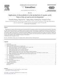
The geometry of the model is schematically<br />
shown in Fig. 1. The hot saline solution (h) flows<br />
in direct contact with hydrophobic microporous<br />
membranes (m), <strong>and</strong> the cold solution (c) flows<br />
on the cold side of the membrane. The tempera-<br />
ture difference between the hot <strong>and</strong> cold faces of<br />
the membrane causes the vapor pressure of the<br />
concentrated solution to be higher than that of the<br />
cold fluid; as a result, water starts to evaporate at<br />
the hot side of the membrane, penetrates through<br />
the membrane pores, <strong>and</strong> then is convected to <strong>and</strong><br />
condensed on the cold fluid (c) or condensed in a<br />
film (/3 on a cooling plate (p).<br />
MD systems can be classified into four con-<br />
figurations, according to the nature of the cold<br />
side of the membrane: (1) direct contact mem-<br />
brane <strong>distillation</strong> (DCMD), in which the mem-<br />
brane is in direct contact only with liquid phases,<br />
saline water on one side <strong>and</strong> fresh water on the<br />
X<br />
oat<br />
1N<br />
i I '<br />
~:~<br />
I~1 ~i~<br />
ir<br />
$<br />
.6. d~<br />
pc ice<br />
......... i<br />
o~<br />
Fig. I. MD cell configurations; g, f<strong>and</strong> p included only<br />
in AGMD. h: hot solution, m: membrane, g: air gap, fl<br />
film condensate, p: cooling plate, c: cold solution for<br />
AGMD, cold pure water for DCMD, sweeping air for<br />
SGMD, <strong>and</strong> vacuum for VMD, i: inlet, o: outlet.<br />
other (cf. [7]-[9]; (2) vacuum membrane distilla-<br />
tion (VMD), in which the vapor phase is<br />
vacuumed from the liquid through the membrane,<br />
<strong>and</strong> condensed, if needed, in a separate device<br />
(cf. [10,11]); (3) air gap membrane <strong>distillation</strong><br />
(AGMD), in which an air gap is interposed<br />
between the membrane <strong>and</strong> the condensation<br />
surface (of. [12,13]); <strong>and</strong> (4) sweeping gas mem-<br />
brane <strong>distillation</strong> (SGMD), in which a stripping<br />
gas is used as a carrier for the produced vapor,<br />
instead of vacuum as in VMD (cf. [ 14--18]).<br />
Because AGMD <strong>and</strong> DCMD do not need an<br />
external condenser, they are best suited for appli-<br />
cations where water is the permeating flux.<br />
SGMD <strong>and</strong> VMD are typically used to remove<br />
volatile organic or dissolved gas from an aqueous<br />
solution.
2. <strong>Membrane</strong> materials<br />
2.1. <strong>Membrane</strong> properties <strong>and</strong> characteristics<br />
<strong>Membrane</strong>s used in membrane <strong>distillation</strong><br />
should ihave the following properties:<br />
1. Be thin, since the permeate flux is inversely<br />
proportional to the membrane thickness. The<br />
other requirements pertain to the non-wetting<br />
condition. The solution brought into contact with<br />
the membrane must not penetrate the pores of the<br />
membnme. This can be quantified by the Laplace<br />
(Cantor) equation<br />
2Y1<br />
APcn~y - -- cos 0 (1)<br />
rp.max<br />
where LLPo,~y is the entry pressure difference, Yt is<br />
the surthee tension of the solution, 0 is the angle<br />
of contact between the solution <strong>and</strong> the membrane<br />
surface, <strong>and</strong> rp,r~x is the largest pore size. In<br />
view of'(1), these non-penetration conditions are:<br />
2. Have reasonably small pore size (rp, on the<br />
order of #m in MD).<br />
3. High surface tension, y~, of the feed<br />
solution in contact with the membrane.<br />
4. Low surface energy of the membrane<br />
material. <strong>Membrane</strong> materials suitable for MD,<br />
which have been used by many researchers, are<br />
polyteta'afluoroethylene (PTFE), polyvinylidenefluoride<br />
(PVDF), polyethylene (PE), <strong>and</strong> polypropylene<br />
(PP). Those material are hygrophobic (i.e.,<br />
they have low surface energy). The surface<br />
energy of these materials is listed in Table 1.<br />
5. Fouling of the membranes may be an important<br />
issue that needs to be investigated further.<br />
Table 2 lists a number of membranes used for<br />
MD anti their properties with the literature references<br />
of the studies in which they were used. The<br />
porosiE¢ of the membranes used is in the range of<br />
0.06 to 0.85, <strong>and</strong> the pore size is in the range of<br />
0.2 to 1.0 #m. The thickness is in the range of<br />
0.06 to 0.25 mm with the exception of [22]. The<br />
thermal conductivities of polymers are dependent<br />
A.M. AlklaibL N. Lior / Desalination 171 (2004) 111-131 113<br />
Table 1<br />
Surface energy of some material used in MD [19]<br />
<strong>Membrane</strong> material Surface energy (kN/m)<br />
PTFE 9.1<br />
PP 30.0<br />
PVDF 30.3<br />
PE 33.2<br />
upon both temperature <strong>and</strong> the degree ofcrystalli-<br />
nity [20]. As a result, the reported values of<br />
k,, can span a fairly large range: PP, 0.15-<br />
0.20 Wm-IK-1; PVDF <strong>and</strong> PTFE, 0.22-<br />
0.45 Wm -1K -1 [21].<br />
2.2. <strong>Membrane</strong> modules<br />
Different module configurations were used to<br />
conduct experimental work in MD. Those used<br />
by Kimura <strong>and</strong> Nakao [30], Banat [13], <strong>and</strong> Hsu<br />
et al. [29] look like the one depicted in Fig. 2a. In<br />
this module, a membrane was inserted between<br />
two cylindrical compartments (perpendicular to<br />
the cylinder axis), with the hot feed solution<br />
flowing in one compartments <strong>and</strong> cold water in<br />
the other. The dimensions of these compartments<br />
are different for each experimental study. The<br />
cylinder has a length of 12 cm <strong>and</strong> a diameter of<br />
6 cm [29], 15 cm <strong>and</strong> 8 cm [30], <strong>and</strong> 15 cm <strong>and</strong> 5<br />
cm [ 13 ]. Separating the two compartments are the<br />
membrane, an air gap <strong>and</strong> a cooling plate in<br />
AGMD, <strong>and</strong> only the membrane in the DCMD<br />
configuration.<br />
The modules used by Ohta et al. [39,40] <strong>and</strong><br />
Liu et al. [36] with an air gap resemble that<br />
depicted in Fig. 2b. The dimension of the flow<br />
channel [39] is 840 mm long, 390 mm wide, <strong>and</strong><br />
80 mm high; 840 mm long, 390 mm wide, <strong>and</strong> 57<br />
mm high [40]; <strong>and</strong> 200 mm long, 100 mm wide,<br />
<strong>and</strong> 10 mm high [36].<br />
To avoid the use of membrane supports, the<br />
Lawson <strong>and</strong> Lloyd module [34,35] has a very<br />
small square cross sectional area (0.63 x0.63 cm),
l 14 A.M. A lklaibi, N. Lior / Desalination 171 (2004) 111-131<br />
(A)<br />
!' t ,<br />
d I !<br />
, il I11{ ,<br />
d an I I<br />
(c)<br />
; ii Hli :<br />
] ql BII a<br />
] A HI I [<br />
l~r~ "~a, ler li<br />
~lak~<br />
Fig. 2. Schematic of some of the MD modules.<br />
(a) Adopted from [30]; (b) Adopted from [21]; (c) Adop-<br />
ted from [34], (d) Adopted from [37].<br />
the same as the channel height, as shown in<br />
Fig. 2c.<br />
The modules ofMartinez et al. [37] <strong>and</strong> Mar-<br />
tinez <strong>and</strong> Florido-Diaz [8] look like that depicted<br />
in Fig. 2d. This module is composed of two<br />
symmetrical rectangular channels between which<br />
the flat-sheet membrane is s<strong>and</strong>wiched. Each<br />
compartment is made of nine channels. The<br />
dimensions of the channel are 55 mm long, 7 mm<br />
wide <strong>and</strong> 0.4 mm deep.<br />
I¢"<br />
(B)<br />
(D)<br />
Supp<br />
erme<br />
---4" - Entrance of cold stream<br />
b Exit of cold stream<br />
- Entrance of hot stream<br />
Exit of hot stream<br />
Separator<br />
<strong>Membrane</strong><br />
Separator<br />
Some comments on these modules are in<br />
order. Because the inlet of the channel in Fig. 2a<br />
is off the membrane surface, the evaporation<br />
takes place at a temperature <strong>and</strong> velocity that are<br />
lower than that of the inlet, resulting in a lower<br />
permeate flux. The modules of Fig. 2b <strong>and</strong> 2c do<br />
not have this shortcoming. However, the channel<br />
width for the studies in Fig 2c <strong>and</strong> Fig. 2d makes
the area of the channel unrepresentative of<br />
practical use. The modules do not represent a cell<br />
of an integrated MD system.<br />
3. Applications of membrane <strong>distillation</strong><br />
AGMD <strong>and</strong> DCMD are best suited for appl-<br />
ications where water is the major permeate com-<br />
ponent. Several researchers applied these two<br />
configurations to produce fresh water from a salt<br />
solution. Characteristics of the membranes are<br />
listed in Table 2. Table 3 lists the permeate flux<br />
they found at the given conditions. Results were<br />
in the range between 2.8 <strong>and</strong> 129 kg/m2h for<br />
DCMD <strong>and</strong> between 5 to 28 kg/m2h for AGMD.<br />
The permeate flux average value for all the<br />
experiments reported in Table 3 is 26 kg/mZh.<br />
The experiments of Ohta et al. [39], Kurokawa<br />
<strong>and</strong> Sawa [32] <strong>and</strong> Drioli et al. [25] have<br />
produced relatively low fluxes compared to that<br />
of Lawson <strong>and</strong> Lloyd [33]. Lawson et al. [33]<br />
attributed the higher values to design of the<br />
module. Using AGMD, Liu et al. [36] <strong>and</strong> Banat<br />
[ 13] found almost the same values. But Hsu et al.<br />
[29] found 5-fold lower values, maybe because a<br />
lower feed temp-erature was used. Hsu et al. [29]<br />
found that the flux produced by DCMD is higher<br />
than that produced by AGMD by 8-fold at the<br />
same conditions. It should be emphasized that<br />
the wide variation of permeate flux among re-<br />
searchers c, annot be explained merely by the fact<br />
that they used different conditions. It is impera-<br />
tive to know the maximum permeate flux of MD<br />
under optimal conditions so that the viability of<br />
the process can be assessed <strong>and</strong> compared with<br />
other <strong>desalination</strong> processes such as RO or MSF.<br />
More expe, rimental work needs to be dedicated<br />
towards that objective.<br />
For comparison, the range of permeate fluxes<br />
in typical commercial RO processes is 12-15 kg/<br />
m2h for seawater <strong>and</strong> 18-26 kg/m2h for brackish<br />
water. Since MD fluxes are not very sensitive to<br />
salinity, this is up to 9-fold lower than the highest<br />
A.M. Alklaibg N. Lior / Desalination 171 (2004) 111-131 115<br />
obtained in the reported MD experiments. In<br />
advanced commercial MSF plants they are about<br />
1,200 kg/m2h, about 10-fold higher.<br />
The last column of Table 3 lists the mass<br />
transfer coefficient defined as<br />
_to,)<br />
that reaches a value of 1,560 Jm-2s-tK-~ in the<br />
reported experiments. For comparison, data from<br />
an advanced operating MSF plant show that KM<br />
11,700 kg m -2 s- 1, 7.5-fold higher. It is important<br />
to note though that the dimensions of the MSF<br />
plant are orders of magnitude larger than those of<br />
a comparable MD plant, <strong>and</strong> the used material is<br />
much heavier <strong>and</strong> more expensive, discussed in<br />
greater detail below.<br />
In addition to producing water, membrane<br />
<strong>distillation</strong> has been used for concentration of<br />
juice <strong>and</strong> wastewater treatment as shown in<br />
Table 4. Nene et al. [38] employed MD to con-<br />
centrate raw cane sugar <strong>and</strong> found that at steady<br />
state; the water flux from the cane sugar was<br />
10 kg/m2h.<br />
4. Effects of the fundamental operating para-<br />
meters<br />
The fundamental operating parameters of the<br />
MD process are the hot feed solution temperature,<br />
Thi; the mass flow rate of feed solution, nih; the<br />
air/vapor gap thickness, 6g; <strong>and</strong> the coolant mass<br />
flow rate, nic; or the circulating sweeping velo-<br />
city, uci in the SGMD. This section includes the<br />
effects of these parameters on the permeate flux<br />
in MD systems.<br />
4.1. Effect of the saline solution temperature<br />
Several researchers have studied the effect of<br />
the feed temperature on the permeate flux, <strong>and</strong>
116 A.M. Alklaibi, N. Lior / Desalination 171 (2004) 111-131<br />
Table 2<br />
<strong>Membrane</strong>s used by some researchers reviewed in this paper<br />
Reference <strong>Membrane</strong> material e rv. #m 6,, mm Company Model<br />
Banat [ 13] PVDF 0.75 0.45 0.11 Millipore N/A<br />
B<strong>and</strong>ini <strong>and</strong> Sarti [22] PP N/A 0.2 1.5 Akzo-Nobel Accurel<br />
Basini et al. [ 14] pp N/A N/A N/A N/A N/A<br />
Calabro et al. [23] PP 0.70 0.45 N/A N/A N/A<br />
Calabro et al. [24] PVDF 0.75 0.11 0.14 Millipore N/A<br />
Drioli <strong>and</strong> Wu [25] Teflon N/A N/A N/A Gelman N/A<br />
Teflon N/A N/A N/A Surnitomo Chem. N/A<br />
Drioli <strong>and</strong> Wu [26] PP 0.7 0.43 0.15 Enka AG N/A<br />
Guijt et al. [27] N/A 0.5 0.45 0.096 N/A N/A<br />
Guijt et al. [28] PP N/A 0.4-0.6 0.15 Akzo Nobel PP1 LX150/330<br />
PP 0.7 0.1 0.055 Mitsubishi EHF270FA 16<br />
PP N/A 0.2 0.25 Millipore UPE<br />
Hanbury <strong>and</strong> Hodgkiess [5] PTFE N/A N/A N/A Goretex N/A<br />
Hsu et al. [29] PTFE 0.70 0.20 0.175 Millipore Fluropore<br />
PTFE 0.85 0.5 0.175 Millipore Fluropore<br />
Khayet et al. [15, 16] PTFE 0.80 0.20 0.178 Gelman Science TF-200<br />
Khayet et al. [15,16] PTFE 0.80 0.45 0.178 Gelman Science TF-450<br />
Kimura <strong>and</strong> Nakao [30] PTFE N/A 0.2-3 0.08 Nitto Electric N/A<br />
Kubota et al. [31] PTFE 0.75 N/A 0.1 N/A N/A<br />
Kurokawa <strong>and</strong> Sawa [32] PTFE N/A 0.20 N/A N/A N/A<br />
Lagana et al. [33] PP 0.7 0.45 0.12 Enka MD-020-2N-CP<br />
Lawson <strong>and</strong> Lloyd [34,35] PP 0.66 0.29 0.091 3M MA<br />
PP 0.76 0.40 0.081 3M bib<br />
PP 0.79 0.51 0.076 3M MC<br />
PP 0.80 0.58 0.086 3M MD<br />
PP 0.85 0.73 0.079 3M ME<br />
Liu et al. [36] PTFE 0.85 1.0 0.150 Millipore N/A<br />
Martinez et al. [37] PTFE 0.80 0.20 0.06 Gelman Instr. TF200<br />
Martinez <strong>and</strong> Florido [8] PVDF 0.70 0.45 0.125 Millipore Durapore<br />
HVHP45<br />
PVDF 0.75 0.22 N/A Milliport Durapore<br />
GVHP22<br />
Nene et al. [38] PP N/A 0.2 N/A Akzo Wuppertal<br />
Ohta et al. [39] Fluoro-carbon N/A N/A 0.13 N/A N/A<br />
Sarti et al. [41] PTFE 0.6 1.0 0.6 Gelman Inst. TF1000<br />
PTFE 0.6 2.0 0.6 Gelman Inst. TF200<br />
Schofield et al. [6] PP 0.75 0.10 0.100 Enka N/A<br />
PP 0.75 0.2 0.14 Enka N/A<br />
PVDF 0.75 0.45 O. 11 Milliport Durapore<br />
Schofield et al. [42,43] PVDF 0.75 0.45 0.110 Millipore Durapore<br />
Ugrozov et al. [44] Copolymer of 0.7 0.25 0.12 N/A MFF-2<br />
PTFE <strong>and</strong> PVDF
A.M. AlklaibL N. Lior / Desalination 171 (2004) 111-131<br />
Table 3<br />
Permeate :fluxes <strong>and</strong> mass transfer coefficients in MD of NaC1 solutions, as obtained in several studies<br />
Reference: MD T,,, Tcj, (T,i-Ta), wsi 5g, Flow rate, J, KM,<br />
configuration °C °C °C mm l/min kg/m2h j/m2sK<br />
Hsu et al. [29] DCMD 45 20 25 0.030 0 3.3 40 1070<br />
Drioli et al. [25] DCMD 50 20 30 0.0058 0 N/A 5 111<br />
Martinez <strong>and</strong> Florido [8] DCMD 50 14 36 0.058 0 1.2 28 519<br />
Kurokawa <strong>and</strong> Sawa [32] DCMD 90 50 40 N/A 0 0.31 4.6 77<br />
Lawson <strong>and</strong> Lloyd [35] DCMD 75 20 55 0.035 0 3.78 129 1560<br />
Ugrozov et al. [44] DCMD 70 10 60 0 0 4.17 17 189<br />
Ohta et al. [39] DCMD 60 25 35 0 0 0.06 m/s 2.8 53<br />
Banat [13] AGMD 90 7 82 0.001 8 4.5 26 211<br />
Hsu et al. [29] AGMD 45 20 25 0.03 5 3.3 5 133<br />
Liu et al. [36] AGMD 75 20 55 0.003 4 3.8 28 339<br />
Guijit et al. [27] AGMD 90 65 25 0 4 0.02 7 187<br />
Khayet et al. [15] SGMD 50 20 30 0 N/A 0.21 m/s 21 467<br />
Table 4<br />
Permeate fluxes, as obtained by several studies, in concentration <strong>and</strong> treatment processes of various liquids (Brix is a scale<br />
used to measure dissolved solid concentrations in water)<br />
Reference Application Configuration Feed rhh, w s Thi , Tci, p, (Th:Tci),J ,<br />
solution 1/min °C °C kPa °C kg/m2h<br />
Calabro et al. Wastewater DCMD Blue E-G 0.026 0.05 50 45 -- 5 0.18<br />
[23] treatment<br />
Nene et al. Concentration DCMD Sugar 1 20 Brix 75<br />
[28] of raw cane cane<br />
sugar<br />
Calabro et al, Concentration DCMD Orange 5 108 g/1 45<br />
[24] of orange juice juice<br />
35<br />
B<strong>and</strong>ini et al. Concentration VMD Glucose 2.5 50 Brix 50<br />
[22] of must<br />
Lagana et al. Concentration DCMD Apple juice 3.3<br />
[33] of apple juice<br />
35<br />
30 Bfix 50<br />
35<br />
0.265 32<br />
117<br />
40 10 0.342<br />
35 15 0.432<br />
25 -- 50 10<br />
20 25 10<br />
22<br />
7<br />
0.1 - -<br />
0.1<br />
0.1<br />
0.1<br />
15<br />
- - 10<br />
m 25<br />
5.4<br />
5.4<br />
2.52<br />
7.2<br />
2.88<br />
1
118 A.M. Alklaibi, N. Lior / Desalination 171 (2004) 111-131<br />
Table 5<br />
Effect of feed temperature on the permeate flux<br />
Reference Flow rate, ws Tc~, Range of Range of n-fold increase in J<br />
l/min °C Thi, °C (Th~ -Tc~), °C for given temp. range<br />
Liu et. al. [36] 0.063 0.005 20 50-70 30-50 2.83<br />
Martinez <strong>and</strong> Florido [8] 0.48 0.058 14 50-70 36-56 3.0<br />
Banat [13] 4.5 0.014 20 50-70 30-50 3.0<br />
Ohta et a1.[39] 0.3 rn/s 0 25 40-60 15-35 3.5<br />
Jonsson [7] N/G 0 20 50-70 30-50 3.5<br />
Ugrozov et al. [44] 0.33 0 10 40-70 30-60 3.5<br />
Table 6<br />
Effect of coolant temperature on the permeate flux<br />
Reference Flow rate, w s Thl, °C Range of Range of n-fold increase in J<br />
1/min Tci, °C (Th~ -Tel), °C for given temp. range<br />
Banat [13] 4.5 0.0125 60 10-30 50-30 1.18<br />
Lawson <strong>and</strong> Lloyd [33] 3.78 0 59 9-29 50-30 1.4<br />
Jonsson [7] N/A 0 60 10-30 50--30 2.0<br />
Kurokawa <strong>and</strong> Sawa [32] 0.31 0 90 25-50 65-40 1.23<br />
Table 5 lists their results. As seen, the feed<br />
solution temperature has a major effect on the<br />
permeate flux. This increase is larger at higher<br />
temperatures because the vapor pressure increases<br />
exponentially with temperature.<br />
4.2. Effect of the coolant temperature<br />
The effect of the coolant temperature in<br />
several studies is listed in Table 6. The coolant<br />
temperature has a more than 2-fold smaller effect<br />
on the flux than that of the feed solution for the<br />
same temperature difference. This is because the<br />
vapor pressure increases more than linearly with<br />
temperature.<br />
4.3. Effect of mass flow rate of the feed solution<br />
The effect of the mass flow rate of the feed<br />
solution in the hot channel, as found by several<br />
researchers, is shown in Table 7. The results<br />
show that the permeate flux increases with the<br />
mass flow rate. The effect of the mass flow rate<br />
is, however, 2.5-fold weaker than that of the feed<br />
temperature. Kubota et al. [30] conducted experi-<br />
ments on membrane <strong>distillation</strong> <strong>and</strong> stated that<br />
the permeate flux increases with the mass flow<br />
rate until it reaches a maximum, <strong>and</strong> then<br />
decreases, Most of the researchers, however,<br />
show that the flux increases to an asymptotic<br />
value with the increase in mass flow rate<br />
(cf. Banat [13]). The boundary layer thickness<br />
decreases with the increase in the flow velocity,<br />
but then this effect does not change with further<br />
increase of the velocity.<br />
4.4. Effect of coolant mass flow rate<br />
The effect of the coolant mass flow rate, as<br />
found by different researchers, is shown in<br />
Table 8. Banat [7] found that the cooling water<br />
flow rate had a minimal effect (not noticeable) on
Table 7<br />
Effect of tile feed solution flow rate on the permeate flux<br />
A.M. AlklaibL N. Lior / Desalination 171 (2004) 111-131<br />
Reference /'hi, Ta, (Thi-Tci), °C w~ Range of feed n-fold increase in J<br />
°C °C flow rate, 1/min for given flow rate<br />
Banat [13] 60 20 53 0.033 2-5 1.2<br />
Martinez et al. [37] N/G 14 -- 0.058 0.6-1.2 0.125<br />
Ohta et al. [39] 60 25 35 N/A 0.02-0.08 m/s 1.83<br />
Ugrozov et al. [44] 60 10 50 0 1.33-4.17 1.37<br />
Table 8<br />
Effect of coolant flow rate on the permeate flux<br />
Reference Range of hi c Thi, °C Tci, °C ws n-fold increase in<br />
J for given ni c<br />
Banat [13] 1-5 1/min 60 20<br />
Ohta et al. [39] 0.02-0.08 m/s 60 20<br />
the permeate flux. Ohta et al. [39] found that<br />
increasing the coolant velocity from 0.02 to<br />
0.08 m/s resulted in a 1.5-fold increase of the<br />
permeate flux. In the same study he showed that<br />
hot feed velocity increased the flux by 2.0-fold.<br />
This implies that the effect of the coolant velocity<br />
is less significant than that of hot feed.<br />
4.5. Effect of the width of the air~vapor gap<br />
The effect of the air/vapor gap width on the<br />
permeate flux is listed in Table 9. The results<br />
show that the flux increases as the gap is made<br />
smaller. The decrease in the air gap increases the<br />
permeate flux by about 2-fold. Jonsson et al. [6]<br />
reported that the effect of the air gap becomes<br />
even more significant for vapor/air gaps thinner<br />
than 1 mrn.<br />
4. 6. Effects of the sweeping gas conditions in<br />
SGMD<br />
Table 10 lists the effect of the sweeping gas<br />
0.104 No noticeable<br />
effect<br />
0 1.5<br />
119<br />
velocity as reported by Basini et al. [12] <strong>and</strong><br />
Khayet et al. [10,19]. It is concluded that the<br />
sweeping gas velocity is a crucial operating para-<br />
meter in determining the process rate, up to a<br />
value in which the rate determining resistance is<br />
offered by the porous membrane itself. Interest-<br />
ingly, the permeate flux increased with the en-<br />
trance humidity of the sweeping air, since dry air<br />
consumes some of the produced air for its own<br />
humidification. The production also increased as<br />
gas temperature was decreased, <strong>and</strong> was weakly<br />
affected by the feedwater velocity.<br />
4. 7. Effect of feed concentration<br />
Schofield et al. [41 ] studied experimentally the<br />
effect of the concentration of NaCI <strong>and</strong> sucrose<br />
solutions on permeate flux, <strong>and</strong> found that the<br />
flux reduction caused by 30 wt% sucrose is less<br />
than that caused by 25% wt% NaC1 under the<br />
same conditions of feed velocity <strong>and</strong> temperature<br />
<strong>and</strong> using the same PVDF membrane. This is<br />
mainly due to the higher molecular weight
120 A.M. AlklaibL N. Lior / Desalination 171 (2004) 111-131<br />
Table 9<br />
Effect of air gap width on the permeate flux<br />
Reference ~,,, mm The, °C T d, °C ws n-fold increase of Jas the gap is<br />
made smaller in the range tested<br />
Jonsson et al. [12] 5-1 60 20 0 3.5<br />
Liu et al. [36] 5-1 55 20 0.003 2.0<br />
Guijit et al. [27] 5-1 80 65 N/A 2.3<br />
Table 10<br />
Effect of sweeping gas velocity on the permeate flux<br />
Reference /'hi , °C Ta, °C ud, m/s n-fold increase of J as sweeping<br />
gas velocity increases<br />
Basini et al. [14] 58 30 1-3 2<br />
Khayet et al. [15,16] 65 20 0.5-1.5 2<br />
Table 11<br />
Effect of feed solution (aqueous, NaCI) concentration on the permeate flux<br />
Reference Th~ , Ta, Flow rate, w, Percentage decrease in<br />
°C °C l/rain J for given ws<br />
Banat [13] 55 7 5.5 0.001-0.01 6<br />
Lawson <strong>and</strong> Lloyd [33] 80 20 3.78 0-0.0754 7<br />
fraction of the sucrose: for the same weight<br />
fraction, the mole fraction for sucrose is smaller,<br />
resulting in a lower vapor pressure reduction than<br />
that due to NaC1, <strong>and</strong> the main reason for the flux<br />
reduction in the sucrose solution is its increased<br />
viscosity. Effects of feed concentration reported<br />
by others are listed in Table 11.<br />
4.8. Effect of noncondensable gases<br />
In all practical <strong>desalination</strong> <strong>distillation</strong> pro-<br />
cesses, non-condensable gases evolve alongside<br />
with the vapor, including both gases dissolved in<br />
the feed water <strong>and</strong> other gases, primarily carbon<br />
dioxide from the thermal decomposition of bicar-<br />
bonates. In membrane <strong>distillation</strong> these gases will<br />
be absorbed into the membrane pores <strong>and</strong> may<br />
well tend to reduce vapor flux; they are also<br />
likely to reduce the condensation heat transfer<br />
coefficient.<br />
Another important consideration is that the<br />
presence of air may cause the vapor transport rate<br />
to be mass transfer limited (because of the addi-<br />
tional mass transfer resistance it presents to vapor<br />
diffusion) where improved heat transfer coeffi-<br />
cients then have a relatively small effect on the<br />
flux, <strong>and</strong> deaerated liquids typically make the<br />
transport rate heat transfer limited where im-<br />
proved heat transfer coefficients increase this<br />
rate.<br />
A common way to deal with the problem of<br />
noncondensables in <strong>desalination</strong> <strong>distillation</strong> is to<br />
deaerate the feedwater prior to <strong>distillation</strong>. In<br />
MD, the feed <strong>and</strong>/or the permeate can be deaera-
ted prior to entering the module, which causes the<br />
partial pressure of the air in the membrane to<br />
decrease due to equilibrium considerations. This<br />
way of deaeration will increase the pressure<br />
difference across the liquid/gas interface, thus<br />
increasing the tendency for membrane wetting<br />
[43]. Another technique for reducing the effect of<br />
the air is by lowering the pressure of the feed<br />
<strong>and</strong>/or the permeate. This method lowers the<br />
pressure difference across the membrane, hence<br />
reducing the tendency for the membrane wetting.<br />
Using the second method, Schofield et al. [43]<br />
studied experimentally the effect of air on the<br />
transport through the membrane <strong>and</strong> on the<br />
resulting permeate flux. Using fresh water as<br />
feed, air pressures from 100 kPa to 10 kPa, <strong>and</strong><br />
Durapore PVDF <strong>and</strong> Enka polypropylene mem-<br />
branes, at temperatures between 25 <strong>and</strong> 90°C, <strong>and</strong><br />
temperature differences between 10 <strong>and</strong> 55°C,<br />
they found that deaeration increased the flux by<br />
increasing the permeability of the membrane, <strong>and</strong><br />
although this also resulted in an increase in<br />
temperature polarization, the net effect was found<br />
to be an increase of the flux by 40% (when the<br />
deaeration was extrapolated to zero air pressure)<br />
above that of a non-deaerated feed. They also<br />
found that deaeration improved the process heat<br />
efficiency defined below by Eq. (3) since the<br />
resulting :increase in permeate flux in-creased QL<br />
while keeping Qc unchanged. This topic deserves<br />
more detailed study.<br />
5. <strong>Membrane</strong> fouling<br />
Fouling is the deposition process of particles,<br />
colloids, emulsions, suspensions <strong>and</strong> macromole-<br />
cules on or in the membrane, with subsequent<br />
detrimental effects on the process <strong>and</strong> the mem-<br />
brane. The consequences of fouling include<br />
foulant adsorption, pore blocking, <strong>and</strong> cake for-<br />
mation. Fouling obviously has a very important<br />
impact on the effectiveness <strong>and</strong> the life of the<br />
membrane.<br />
A.M. Alklaibi, N. Lior / Desalination 171 (2004) 111-131 121<br />
Lawson <strong>and</strong> Lloyd [21 ] stated that fouling is<br />
less of a problem in MD than in other membrane<br />
separations. The premise is that the pores are<br />
relatively large compared to the "pores" or diffu-<br />
sion pathways in RO or ultrafiltration (UF) (both<br />
have pore sizes
122 A.M. AlklaibL N. Lior / Desalination 171 (2004) 111-131<br />
attributed the biofouling limitation to operation at<br />
high concentration <strong>and</strong> temperature, but they did<br />
not show the fouling extent as a function of<br />
temperature <strong>and</strong> concentration.<br />
Using three different feed solutions: (1) raw<br />
seawater, (2) raw water pretreated by 0.1 /~m<br />
microfiltration, <strong>and</strong> (3) 3% NaCI, Hsu et al. [29]<br />
studied the effect of the type of feed solution on<br />
fouling in a DCMD configuration with a PTFE<br />
membrane from Millipore at Thi = 45°C, To; =<br />
20°C <strong>and</strong> a 3.3 l/min flow rate. The test period<br />
was 160 h. It was found that:<br />
1. The pretreatment ofthe raw water increases<br />
the permeate flux by about 25%.<br />
2. The permeate flux obtained from the 3%<br />
NaC1 feed solution was twice as high as that<br />
obtained from raw seawater.<br />
It is a general conclusion that pretreatment has an<br />
important positive influence on MD.<br />
As noted in Section 4.8, deaeration of the<br />
feedwater, another pretreatment process, was<br />
shown by the small amount of available data to<br />
improve performance.<br />
6. Heat efficiency<br />
The process heat efficiency in MD can be<br />
defined as<br />
tit - (3)<br />
Qr<br />
where QL is the latent heat needed in the evapo-<br />
ration process, <strong>and</strong> Qr is the total heat input, both<br />
per unit mass of permeate,<br />
Qr : QL + Qc (4)<br />
where Qc is the heat lost by conduction.<br />
B<strong>and</strong>ini et al. [47] have shown that thermal<br />
efficiency for pure water does not depend on the<br />
membrane thickness. They defined the two<br />
parameters W l <strong>and</strong> W2 as<br />
1<br />
1/h h + 1/h e k m<br />
rr,- , ze2-<br />
Khfg / 6m Khfg<br />
(5)<br />
where K is the permeability of the membrane.<br />
While W1 is a ratio of the thermal conductivity of<br />
the liquid phases to that of the membrane, W 2<br />
involves only properties of the membrane <strong>and</strong> the<br />
latent heat of the liquid, <strong>and</strong> is independent of<br />
membrane thickness. When W t is high (>10), the<br />
transmembrane flux is controlled by the membrane<br />
properties, so that higher fluxes can be<br />
achieved by more permeable or thinner membranes.<br />
It is also stated in the result that a minimum<br />
membrane thickness needs to be exceeded<br />
in order to obtain a positive distillate flux. This is<br />
important in the case where the temperature<br />
difference between the two membrane sides is<br />
very small. The presence of the salt may then<br />
reduce the temperature at the hot side of the<br />
membrane below that at the cold side of the<br />
membrane, reversing the flux direction to be from<br />
the cold to the hot side. Practically, this case is of<br />
no interest in MD since (Th, . -T,,c) by far exceeds<br />
the threshold temperature. For instance, for a<br />
20,000 ppm salt (unspecified) solution at Thi =<br />
60°C, the threshold temperature is only 0.13°C<br />
[61.<br />
The conductive heat loss Qc per kg transmembrane<br />
flux J is<br />
Qc _ Rm (Thm-Tmc)<br />
J K(Pvh,-Pv,,~)<br />
(6)<br />
The coefficient Rm/K was obtained experiment-<br />
ally by Martinez et al. [37] for the PTFE mem-<br />
brane with characteristics listed in Table 2. The<br />
experiment was carried out at flow rate of<br />
0.016 l/min <strong>and</strong> 1 molar feed concentration. The<br />
feed water temperature range was 21 to 48°C, <strong>and</strong><br />
the cold temperature was maintained at 14°C.<br />
Under these conditions R,,/K was found to be
A.M. Alklaibi, N. Lior / Desalination 171 (2004) 111-131<br />
Table 12<br />
Conductive heat loss per kg permeate flux <strong>and</strong> heat efficiency as a function of feed temperature<br />
Reference The, °C Tci, °C (Th~- Tc~),°C Qc/J , kJ/kg q,<br />
Kubota et al. [31] 35 25 10 550 0.81<br />
40 15 490 0.83<br />
45 20 470 0.84<br />
Martinez et al. [37] 29 14 15 4000 0.38<br />
41 27 3000 0.44<br />
48 34 2500 0.49<br />
Jonsson et al.[ 12] 40 20 20 550 0.81<br />
60 40 250 0.90<br />
80 60 100 0.96<br />
Banat [13] 40 20 20 650 0.76<br />
60 40 350 0.85<br />
80 60 250 0.92<br />
(56±0.05)107 kg m s -4 K -1, <strong>and</strong> a correlation for<br />
Qc/J as a function of (dPv)/(dT) was developed:<br />
(dP) -1<br />
Qc -(0.1±0.3) + (0.56±0.05) -d-T (7)<br />
J<br />
The values of Qc/J at Thi= 31, 27, <strong>and</strong> 21 °C were<br />
found to be around 2500, 3000 <strong>and</strong> 4000 kJ/kg,<br />
respectively. These values, however, are higher<br />
than those reported by others, listed in Table 12,<br />
<strong>and</strong> as a consequence his system has low values<br />
oft b. Qc/Jwas found to decrease as the operating<br />
temperature of the solution increased, <strong>and</strong> thus<br />
the heat efficiency increases as is shown in the<br />
last column of Table 12.<br />
7. Energy requirements <strong>and</strong> cost<br />
7.1. Energy requirements<br />
The input energy needed to raise the tempera-<br />
ture of the feed solution to the designed inlet<br />
temperature of the hot channel is<br />
(8)<br />
where Tsr is the temperature of feed solution at<br />
the source:.<br />
123<br />
The minimum input energy to produce 1 kg of<br />
distillate water is the heat of evaporation<br />
(-2.4 MJ/kg). A portion or all of this high-energy<br />
dem<strong>and</strong> can be covered through the following:<br />
• utilizing low-grade waste energy<br />
• MD with heat recovery<br />
• integrating MD with other <strong>desalination</strong><br />
processes.<br />
7.1.1. Utilizing low-grade waste energy<br />
Using natural waste energy as the heat source,<br />
Carlsson [48] built a 5 m3/d MD system, but<br />
dimensions <strong>and</strong> other details were not given. He<br />
stated that the power consumption of this process<br />
can be as low as 1.25 KWh/m 3 (4.5 KJ/kg pro-<br />
duced fresh water), <strong>and</strong> that the cost would be<br />
reduced in a large-scale plant, but did not relate<br />
that to the area of the membrane or even the<br />
conditions under which this could be attained.<br />
This extremely low energy consumption could<br />
only have been obtained if the thermal energy<br />
consumption had not been included.<br />
7.1.2. MD with heat recovery<br />
The only energy-sensible way to use MD is by<br />
incorporating internal heat recovery, as show in<br />
Fig. 3. The heat transferred to the cooling channel
124 A.M. AlklaibL N. Lior / Desalination 171 (2004) 111-131<br />
Tho T,i<br />
I .<br />
Th~¢i<br />
T°o hx<br />
MD Cell<br />
Fig. 3. <strong>Membrane</strong> <strong>distillation</strong> cell equipped with heat recovery heat exchanger, h, hot steam; c, cold steam; m, membrane;<br />
hx, heat exchanger; Sup, external heat source; hi, inlet of hot channel; ho, outlet of hot channel; ci, inlet of cold channel;<br />
co, outlet of cold channel.<br />
by conduction <strong>and</strong> condensation, Qr [Eq. (2)],<br />
raises the outlet temperature of the water flowing<br />
in cooling channel. A portion of Qr can be<br />
recovered to preheat the feed solution so the pro-<br />
cess heat requirement is reduced. The percentage<br />
of the recovery of the heat depends on the heat<br />
exchanger effectiveness.<br />
Solving for T=x o , Eq. (9) becomes<br />
(9)<br />
Thx, co=~hx(Thx, hi-Thx, ci)+ Thx, ci (10)<br />
The input energy from an external source is<br />
Qreq=l~lhCps(Thi-Tex, co ) (11)<br />
Tho<br />
T~i<br />
For maximum heat recovery T~,co should be as<br />
high as possible. For high T~.co, ~h~ should be as<br />
close to unity as possible, <strong>and</strong> T~.hi should be<br />
maximized, but this will decrease Thi-Tco, <strong>and</strong><br />
that will lower the permeate flux. Obviously,<br />
optimizations should be conducted.<br />
Although many researchers designed their<br />
experimental set-up so that heat recovery is<br />
utilized, few studied the effect of the heat recov-<br />
ery on the process cost. Schneider et al. [49]<br />
mentioned that heat recovery can reduce the cost<br />
up to 4-fold. No analysis was shown, neither was<br />
the consequent effect on the flux investigated.<br />
A heat recovery heat exchanger was included<br />
in the DCMD configuration of Kurokawa <strong>and</strong><br />
Sawa [32]. For conditions of 90 <strong>and</strong> 50°C of the<br />
hot <strong>and</strong> cold solutions, respectively, with a flow<br />
rate of 0.31 l/rain, they showed experimentally<br />
that 66% of the latent heat can be recovered, <strong>and</strong><br />
that 4.6 kg/mZh of permeate flux can be obtained<br />
at a heat input of 0.21 kWh.
7.1.3, Integrating membrane <strong>distillation</strong> with<br />
other saline water <strong>distillation</strong> processes<br />
Using MD as a bottoming process for MSF or<br />
ME, so the hot reject brine from MSF or ME is<br />
the feed solution for the MD which was not<br />
considered yet. Investigation of integrating MD<br />
with RO, however, was carried out by Drioli et al.<br />
[50]. The reject brine from RO is used as the feed<br />
solution for MD. Because MD is much less<br />
sensitive to concentration, more fresh water can<br />
be produced <strong>and</strong> the RO brine volume can be<br />
furthermore reduced in the MD unit. The<br />
reduction of the quantity of brine produced leads<br />
to a lower environmental impact. Their cost<br />
analysis assuming a MD plant installed at a cost<br />
of $116/m 2 is summarized in Table 13. It shows<br />
that the RO+MD combined plant produced more<br />
than twice as much water as the st<strong>and</strong>-alone RO<br />
plant at the same water cost. The st<strong>and</strong>-alone MD<br />
plant produced as much water as the RO+ MD<br />
plant, but at a water cost about 5% higher.<br />
7.2. Estimation of the MD cost<br />
The cost of <strong>desalination</strong> or separation pro-<br />
cesses varies from location to location as the<br />
conditions of the processed water <strong>and</strong> the nature<br />
<strong>and</strong> the size of the plant are different. Many<br />
leading cost components of MD are not yet<br />
known because the process has not been applied<br />
in commercial size to have the cost benefits of<br />
mass production; neither are factors such as per-<br />
meate flux, pretreatment, fouling <strong>and</strong> membrane<br />
life known adequately yet.<br />
Table 13<br />
Cost <strong>and</strong> production rate of RO, MD, <strong>and</strong> RO + MD<br />
plants for a fixed membrane area of$116 m 2 [39]<br />
Process Product/feed Estimated cost of<br />
ratio produced water, $/m 3<br />
Only RO 0.391 1.25<br />
Only MD 0.856 1.32<br />
RO+MD 0.856 1.25<br />
A.M. Alklaibi, N. Lior ~Desalination 171 (2004) 111-131 125<br />
teed<br />
O<br />
dlsttllate<br />
!~CI MD unit M1 ..<br />
~.d 143<br />
~- / - ,,,,, __<br />
1&95) hoar exohanflar H1<br />
~ ater<br />
H?<br />
Fig. 4. Flow diagram for MD plant (adopted from Fane et<br />
al. [51]).<br />
Table 14<br />
Cost data given by Fane et al. [51]; items in the Unit<br />
column correspond to the components in Fig. 4<br />
Unit Capital, $ Utility,<br />
$/t<br />
800 m 2 hollow fiber 150,000 0<br />
MD module<br />
1.4 MW heater (H2) 12,000 2.9<br />
1.4 MW cooler (H3) 12,000 0.2<br />
3.6 MW heat exchangers 60,000 0<br />
for hear recovery (H 1)<br />
120 m3/h, two pumps (P1,P2) 6,000 0.2<br />
240,000 3.3<br />
Nevertheless, a few cost estimates for some<br />
specific cases were made. Fane et al. [51 ] have<br />
estimated the cost for a simple 5000 kg/hr MD<br />
plant with heat recovery shown in Fig. 4. The<br />
detail costing of the plant is shown in Table 14.<br />
For plant capacity (Pcap) of 44,000 t/y, the total<br />
cost (Cr) was calculated in term of the capital cost<br />
(Cca) <strong>and</strong> operating cost (Cop) as<br />
Cr= 3 x Cc x0.10/y/(pcap/y) + Cop = $4.9/t<br />
(12)<br />
They concluded that the costs on this production<br />
scale could be similar to those of RO (scaled to<br />
1987).
126 A.M. AlklaibL N. Lior / Desalination 171 (2004) 111-131<br />
Table 15<br />
Cost estimation data [11]<br />
Bare module factor (BM) 2<br />
Depreciation (% capital cost), y 15<br />
Labor cost (% of capital cost), y 10<br />
<strong>Membrane</strong> cost (module), $/m 3 450<br />
<strong>Membrane</strong> life, y 3<br />
Hours of operation, y 7200<br />
Pump efficiency 0.8<br />
Electricity, S/kWh 0.085<br />
Stream at low pressure, $/kg 0.013<br />
Cooling water 0.15<br />
Sarti et al. [11] roughly estimated the cost of<br />
a benzene removal from wastewater containing<br />
1000 ppm of benzene based on the data listed in<br />
Table 15, <strong>and</strong> the capital cost of $247,000, which<br />
was calculated using cost correlations from<br />
Woods [52]. They estimated the product cost to<br />
be $4.04/m 3.<br />
The process was assessed based on the<br />
required area of the membrane per kg permeate<br />
flux by Hanbury <strong>and</strong> Hodgkiess [5] by both<br />
experiment <strong>and</strong> analysis. They derived the<br />
following semi-empirical expression to compute<br />
the specific membrane area requirement, as<br />
A m 1200.480Cp rh h 1 1 )<br />
j- (Th,i_Tc,o) j T0.17 T0.17 (13)<br />
¢,i C,O<br />
where Cp is KJ/kg.k <strong>and</strong> temperatures are in °C.<br />
For their conditions ofTh, i <strong>and</strong> To,/of90°C <strong>and</strong><br />
20°C, respectively, <strong>and</strong> a feed-to-product ratio of<br />
10, the required specific membrane area was<br />
found to be 450 m2/(kg/s). The product fluxes in<br />
their work were around 27 kg/m2h, near the<br />
average obtained by other researchers, shown in<br />
Table 3. The prices of some of the membranes<br />
that can be used for MD were quoted to us by the<br />
Millipore Co. for small quantities <strong>and</strong> are listed in<br />
Table 16. They are quite high, but this also<br />
Table 16<br />
Prices of some membrane materials suitable for MD<br />
(Millipore Co. small quantity quotation)<br />
Material type Price, $/m z<br />
PVDF 280<br />
PTFE 753<br />
depends on the life of the membrane <strong>and</strong> can be<br />
reduced significantly in mass production.<br />
8. Some benefits <strong>and</strong> <strong>potential</strong> problems of<br />
membrane <strong>distillation</strong><br />
As discussed in Section 4.7, the MD permeate<br />
flux is only slightly affected by the concentration<br />
of the feedwater, <strong>and</strong> thus, unlike other mem-<br />
brane processes, productivity <strong>and</strong> performance<br />
remain roughly the same for high concentration<br />
feedwaters. Because the process can be conducted<br />
at temperatures typically below 70°C, <strong>and</strong> driven<br />
by low temperature difference (20°C) of the hot<br />
<strong>and</strong> the cold solutions, low-grade waste or solar<br />
heat can be used.<br />
The selectivity of membrane <strong>desalination</strong> is<br />
higher than any other membrane process. Pure<br />
water produced by MD was quoted to be com-<br />
pletely pure when using tap water feeds with con-<br />
eentrations as high as 2450 ppm [49]. As shown<br />
in Table 17, the quality was very high compared<br />
to the product concentrations of 100 to 500 ppm<br />
produced by RO <strong>and</strong> 50 ppm produced by MSF<br />
[53].<br />
MD membranes can be fabricated from chem-<br />
ically resistant polymers. Since the membranes in<br />
MD act primarily as a support for a vapor-liquid<br />
interface <strong>and</strong> do not react electrochemically with<br />
the solution, they can be fabricated from almost<br />
any chemically resistant polymers with hydro-<br />
phobic intrinsic properties, <strong>and</strong> that increases<br />
membrane life.<br />
MD systems can be very compact. In com-<br />
parison with conventional MSF process, the
Table 17<br />
Quality of water produced by MD<br />
Reference Feed conc., Quality,<br />
ppm ppm<br />
Banat [7] 50,000 140<br />
Kubota et. al. [31] N/G 0.7<br />
Hanbury <strong>and</strong> Hodgkiess [5] 20,000 1.7<br />
Hsu et al. [18] 30,000 8.4<br />
height of the MSF stage usually in the range of<br />
4--6 m as compared with the height of the -1 cm<br />
height ofa MD cell; 1 m 2 of MD membrane will<br />
thus have a volume of 0.01 m 3 <strong>and</strong> produce,<br />
with current generation configurations, up to 129<br />
kg/m3h (Table 3), yielding a volumetric produc-<br />
tion rate of 12,900 kg/m3h. The corresponding<br />
production rate per m 2 of plant surface area for<br />
MSF is 306.7 kg/m2h [54], <strong>and</strong> considering a 4-m<br />
stage height, the MSF process has a volumetric<br />
production rate of 76.6 kg/m3h, about 40 times<br />
lower.<br />
The energy efficiency of optimized MD plants<br />
with internal heat recovery can be close to that of<br />
commercial MSF plants. A rough estimate is<br />
made here for a MD plant producing 1,000 m3/d<br />
with heat recovery (Fig. 2) <strong>and</strong> with no attempt to<br />
optimize performance, operating at Thi = 75°C,<br />
Tcj = T~,,co = 20°C, The.hi = 70°C, a modest re-<br />
covery heat exchanger efficiency ofrl~ = 0.8, an<br />
experimentally obtained product flux of J =<br />
129 kg/m2h (0.0358 kg/mZs). The highest flux<br />
produced by MD listed in Table 3 to be on the<br />
optimistic side for a 3% NaCI solution results in<br />
a membrane area requirement of 323 m 2. The<br />
saline solution flow rate was thus calculated to be<br />
122 kg/s, <strong>and</strong> choosing a flow channel depth of<br />
0.002 m, <strong>and</strong> the solution velocity corresponding<br />
to the J in the cited experiments, uh --- uc = 1 rn/s<br />
(Re = 5700), <strong>and</strong> assuming for simplicity a single<br />
hot solution channel <strong>and</strong> single cold solution heat<br />
recovery channel, the channel length is 5.3 m <strong>and</strong><br />
A.M. Alklaibi, N. Lior / Desalination 171 (2004) 111-131 127<br />
width 61 m. The heat dem<strong>and</strong> based on Eq. (10)<br />
is estimated then as 660 kJ/kg, equivalent to a<br />
performance ratio of 3.6 (this can be improved<br />
significantly in an optimized plan 0. Assuming a<br />
pump efficiency of 0.85 but considering only the<br />
pumping power needed for flow through the MD<br />
channels, the pumping power consumption is<br />
0.96 kJ/kg-0.0003 kWh/kg, more than an order of<br />
magnitude lower compared with a typical value<br />
of 0.005 kWh/kg in commercial MSF plants [54].<br />
It is likely that in MD with heat recovery the<br />
permeate flux will be lower than assumed above<br />
because the local driving temperature difference<br />
is kept smaller. It is noteworthy that this would<br />
not affect the heat consumption, but would<br />
proportionally increase membrane area, channel<br />
length, <strong>and</strong> pumping power. Thus, if the flux<br />
were reduced 5-fold, the pumping power was<br />
found to increase to about 0.0015 kWh/kg, still<br />
much lower than that needed for MSF.<br />
Since MD is not used massively in commer-<br />
cial applications, the information about ultimate<br />
membrane cost is unavailable to the extent that is<br />
in other membrane processes such as RO.<br />
A key technical requirement is that the<br />
membranes allow only vapor (<strong>and</strong> gas) to pass,<br />
<strong>and</strong> not the feed liquid. This is interpreted by the<br />
membrane wetting condition [Eq. (1)], <strong>and</strong> any<br />
process conditions that lead to pore flooding will<br />
at the least impair product quality, but at most<br />
will incapacitate the process. Conditions that may<br />
cause such problems include membrane aging,<br />
fouling, <strong>and</strong> feedwater contamination by surfac-<br />
tants, but there have not yet been studies in<br />
sufficient detail.<br />
9. Conclusions <strong>and</strong> recommendations<br />
The operating parameters of conventional MD<br />
configurations have the following effects: (1) the<br />
permeate fluxes can significantly be improved by<br />
increasing the hot feed temperature (increasing<br />
the temperature from 50 to 70°C increases the
128 A.M. AlklaibL N. Lior / Desalination 171 (2004) 111-131<br />
flux by more than three-fold), <strong>and</strong> by reducing<br />
the vapor/air gap (reducing the vapor air gap<br />
thickness from 5 to 1 mm increased the flux 2.3-<br />
fold); (2) the mass flow rate of the feed solution<br />
has a smaller effect: increasing it three-fold<br />
increases the flux by about 1.3-fold; (3) the<br />
concentration of the solute has a slight effect:<br />
increasing the concentration by more than five-<br />
fold decreases the flux by just 1.15-fold; (4) the<br />
cold side conditions have a lower effect on the<br />
process than the hot side (the ratio of the increase<br />
in the permeate flux when hot feed temperature<br />
increased to that when the cold temperature<br />
decreases by the same quantity is about 2; (5) the<br />
coolant mass flow rate (within the tested range)<br />
has a negligible effect; (6) the coolant tempera-<br />
ture has a lower effect than the mass flow rate of<br />
the hot solution.<br />
The heat consumption for MD with heat<br />
recovery is comparable to that of MSF plants, but<br />
the pumping power is estimated to be much<br />
lower.<br />
MD has some significant advantages over<br />
other processes, including low sensitivity to feed<br />
concentration <strong>and</strong> the ability to operate at low<br />
temperatures <strong>and</strong> thus uses energy sources such<br />
as waste or solar heat, ability to use relatively<br />
cheap <strong>and</strong> robust membranes, higher resistance to<br />
fouling than other membrane <strong>desalination</strong> pro-<br />
cesses, product quality comparable with other<br />
<strong>distillation</strong> processes <strong>and</strong> higher than that from<br />
RO, <strong>and</strong> high system compactness. There is<br />
<strong>potential</strong> for significant reduction in costs as a<br />
consequence of mass production of membranes<br />
<strong>and</strong> improved internal transport.<br />
The paucity of experimental data <strong>and</strong> the large<br />
scatter in the results indicate that a more intensive<br />
<strong>and</strong> focused research effort in this field is needed,<br />
both in experimentation <strong>and</strong> modeling, where a<br />
central issue is the long-term liquid/vapor selecti-<br />
vity of the membranes, followed by the con-<br />
struction of pilot plants for scale-up studies.<br />
10. Symbols<br />
Am<br />
G --<br />
h m<br />
J<br />
K<br />
k<br />
ni --<br />
p<br />
Pv --<br />
Pco. -<br />
Q --<br />
R<br />
rp,max<br />
Tci --<br />
Thi --<br />
U<br />
Wsi<br />
W ,W2--<br />
X<br />
y<br />
Greek<br />
APe.w --<br />
5 --<br />
g<br />
all<br />
lq~, --<br />
-<br />
<strong>Membrane</strong> area, m 2<br />
Capital cost, S/ton<br />
Operating cost, S/ton<br />
Specific heat, kJ kg-1 K-<br />
Total cost, $/t<br />
Heat transfer coefficient, Wm-2K - t<br />
Latent heat of evaporation, kJ kg-<br />
Length-averaged permeate flux at<br />
hot side of the membrane,<br />
kg m -2 h -t<br />
<strong>Membrane</strong> permeability, s-<br />
Mass transfer coefficient,<br />
J m -2 st K-I<br />
Thermal conductivity, W m-t K-1<br />
Mass flow rate, kg s-<br />
Cooling plate<br />
Water vapor pressure, Pa<br />
Plant capacity, ton/y<br />
Heat transferred, kJ m-2h -~<br />
Thermal resistance, m 2 K W-<br />
<strong>Membrane</strong> pore size, m<br />
Largest membrane pore size, m<br />
Inlet temperature of cold solution,<br />
°C<br />
Inlet temperature of hot solution, °C<br />
Feed solution velocity, m/s<br />
Mass fraction of salt in solution at<br />
the inlet of the channel<br />
Constants in Eq. (5)<br />
Coordinate along the solution flow<br />
Coordinate normal to the solution<br />
flow<br />
Entry pressure difference, Pa<br />
Thickness, m<br />
Porosity of the membrane<br />
Surface tension of liquid, N m-t<br />
Heat exchanger effectiveness,<br />
Eq. (9)
0 ---<br />
Subscripts<br />
A.M. Alklaibi, N. Lior / Desalination 171 (2004) 111-131 129<br />
Process thermal efficiency, Eq. (3)<br />
Angle of contact between solution<br />
<strong>and</strong> membrane surface<br />
C --- Sensible heat<br />
c --- Cold solution<br />
h --- Hot solution<br />
hm --- <strong>Membrane</strong> hot side<br />
hx --- Heat exchanger<br />
i --- Inlet of the channel<br />
L --- Latent heat<br />
m -- <strong>Membrane</strong><br />
mc -- <strong>Membrane</strong> cold side<br />
o -- Outlet of the channel<br />
T -- Total<br />
v -- Vapor<br />
Acknowledgment<br />
The authors are grateful to the Middle East<br />
Desalination Research Center for a grant that par-<br />
tially supported this study.<br />
References<br />
[1] A.M. Klaibi <strong>and</strong> N. Lior, Transport analysis in<br />
membrane <strong>distillation</strong>, Proc. IDA World Congress on<br />
Desalination <strong>and</strong> Water Reuse, Manama, Bahrain,<br />
IDA. Topsfield, MA, USA, 2002.<br />
[2] P.K. Weyl, Recovery of demineralized water from<br />
saline waters. United States Patent 3,340,186, 1967.<br />
[3] M.E. Findley, Vaporization through porous mem-<br />
branes, Ind. Eng. Chem. Des. Dev., 6 (1967) 226-<br />
230.<br />
[4] M.E. Findley, V.V. Tanna, Y.B. Rao <strong>and</strong> C.L. Yeh,<br />
Mass <strong>and</strong> heat transfer relations in evaporation<br />
through porous membranes, AIChE J., 15 (1969)<br />
483-489.<br />
[5] W.T. Hanbury <strong>and</strong> T. Hodgkiess, <strong>Membrane</strong> dis-<br />
tillation -- an assessment, Second World Cong.<br />
Desalination & Water Re-Use, 3 (1985) 287-297.<br />
[6] R.W. Schofield, A.G. Fane <strong>and</strong> C.J.D. Fell, Heat <strong>and</strong><br />
mass transfer in membrane <strong>distillation</strong>, J. Membr.<br />
Sei., 33 (1987) 299-313.<br />
[7] K.W. Lawson <strong>and</strong> D.R. Lloyd, <strong>Membrane</strong> distilla-<br />
tion. II. Direct contact MD, J. Membr. Sci., 120<br />
(1996) 123.<br />
[8] L. Martinez-Diez <strong>and</strong> F.J. Florido-Diaz, Theoretical<br />
<strong>and</strong> experimental studies on membrane <strong>distillation</strong>,<br />
Desalination, 139 (2001) 373-379.<br />
[9] J. Phattaranawik <strong>and</strong> R. Jiraratananon, Direct contact<br />
membrane <strong>distillation</strong>: effect of mass transfer on heat<br />
transfer, J. Membr. Sci., 188 (2001) 137.<br />
[10] S. B<strong>and</strong>ini, C. Gostoli <strong>and</strong> G.C. Sarti, Separation<br />
efficiency in vacuum membrane <strong>distillation</strong>, J.<br />
Membr. Sci., 73 (1992) 217-229.<br />
[11] G.C. Sarti, C. Gostoli <strong>and</strong> S. B<strong>and</strong>ini, Extraction of<br />
organic components from aqueous streams by<br />
vacuum membrane <strong>distillation</strong>, J. Membr. Sci., 80<br />
(1993) 21-33.<br />
[12] A.S. Jonsson, R. Wimmerstedt <strong>and</strong> A.C. Harrysson,<br />
<strong>Membrane</strong> <strong>distillation</strong> -- A theoretical study of<br />
evaporation through microporous membranes,<br />
Desalination, 56 (1985) 237-249.<br />
[13] F.A. Banat, <strong>Membrane</strong> <strong>distillation</strong> for <strong>desalination</strong><br />
<strong>and</strong> removal of volatile organic compounds from<br />
water, Ph.D. Thesis, McGill University, 1994.<br />
[14] L. Basini, G. D'Angelo, M. Gobbi, G.C. Sarti <strong>and</strong><br />
C. Gostoli, A <strong>desalination</strong> process through sweeping<br />
gas membrane <strong>distillation</strong>, Desalination, 64 (1987)<br />
245-257.<br />
[15] M. Khayet, P. Godino <strong>and</strong>J. I. Mengual, Theory <strong>and</strong><br />
experiments on sweeping gas membrane <strong>distillation</strong>,<br />
J. Membr. Sci., 165 (2000) 261-272.<br />
[16] M. Khayet, P. Godino <strong>and</strong> J.I. Mengual, Nature of<br />
flow on sweeping gas membrane <strong>distillation</strong>, J.<br />
Membr. Sei., 170 (2000) 243-255.<br />
[17] C.A. Rivier, M.C. Garcia-Payo, I.W Marison <strong>and</strong><br />
U. von Stocker, Separation of binary mixtures by<br />
thermostatic sweeping gas membrane <strong>distillation</strong> I.<br />
Theory <strong>and</strong> simulations, J. Membr. Sci., 201 (2002)<br />
1-16.<br />
[18] M.C. Garcia-Payo, C.A. Rivier, I.W. Marison <strong>and</strong><br />
U. yon Stocker, Separation of binary mixtures by<br />
thermostatic sweeping gas membrane <strong>distillation</strong> II.<br />
Experimental results with aqueous formic acid<br />
solutions, J. Membr Sci., 198 (2002) 197-210.
130 A.M. Alklaibi, N. Lior / Desalination 171 (2004) 111-131<br />
[19] M. Mulder, Basic Principles of <strong>Membrane</strong> Tech-<br />
nology, 2nd ed., Kluwer, Dordrecht, 1996.<br />
[20] D.W. van Krevelen, Properties pfPolymers, 3rd ed.,<br />
Elsevier, Amsterdam, 1990.<br />
[21] K.W. Lawson <strong>and</strong> D.R. Lloyd, Review membrane<br />
<strong>distillation</strong>, J. Membr. Sci., 124 (1997) 1-25.<br />
[22] S, B<strong>and</strong>ini <strong>and</strong> G.C. Sarti, Concentration of must<br />
through vacuum membrane <strong>distillation</strong>, Desalination,<br />
149 (2002) 253-259.<br />
[23] V. Calabro, E. Drioli <strong>and</strong> F. Matera, <strong>Membrane</strong><br />
<strong>distillation</strong> in the textile wastewater treatment,<br />
Desalination, 83 (1991) 209-224.<br />
[24] V. Calabro, B.L. Jiao <strong>and</strong> E. Drioli, Theoretical <strong>and</strong><br />
experimental study on membrane <strong>distillation</strong> in the<br />
concentration of orange juice, Ind. Eng. Chem. Res.,<br />
33 (1994) 1803-1808.<br />
[25] E. Drioli <strong>and</strong> Y. Wu, <strong>Membrane</strong> <strong>distillation</strong>: an<br />
experimental study, Desalination, 53 (1985) 339-<br />
346.<br />
[26] E. Drioli, Y. Wu <strong>and</strong> V. Calabro, <strong>Membrane</strong> dis-<br />
tillation in the treatment of aqueous solution,<br />
Desalination, 33 (1987) 277-284.<br />
[27] C.M. Guijit, I.G. Racz, J.W. van Heuven, T. Reith<br />
<strong>and</strong> A.B. de Haan, Modeling of a transmembrane<br />
evaporation module for <strong>desalination</strong> of seawater,<br />
Desalination, 126 (1999) 119-125.<br />
[28] C.M. Guijit, G.W. Meindersma, T. Reith <strong>and</strong> A.B. de<br />
Haan, Method for experimental determination of the<br />
gas transport properties of highly porous fibre<br />
membranes: a first step before predictive modeling of<br />
a membrane <strong>distillation</strong> process, Desalination, 147<br />
(2002) 127-132.<br />
[29] S.T. Hsu, K.T. Cheng <strong>and</strong> J.S. Chiou, Seawater<br />
<strong>desalination</strong> by contact membrane <strong>distillation</strong>,<br />
Desalination, 143 (2002) 279-287.<br />
[30] S. Kimura <strong>and</strong> S. Nakao, Transport phenomena in<br />
membrane <strong>distillation</strong>, J. Membr. Sci., 33 (1987)<br />
285-298.<br />
[31] S. Kubota, K. Ohta, I. Hyano, M. Hirai, K. Kikuchi<br />
<strong>and</strong> Y. Murayama, Experiments on seawater dis-<br />
tillation by membrane <strong>distillation</strong>, Desalination, 69<br />
(1988) 19-26.<br />
[32] H. Kurokawa <strong>and</strong> Toshio Sawa, Heat recovery<br />
characteristics of membrane <strong>distillation</strong>, Heat Transl.<br />
Jap. Res., 25 (1996) 3.<br />
[33] F. Lagana, G. Barbieri, E. Drioli, Direct contact<br />
membrane <strong>distillation</strong>: modeling <strong>and</strong> concentration<br />
experiments, J. Membr. Sci., 166 (2000) 1-11.<br />
[34] K.W. Lawson <strong>and</strong> D.R. Lloyd, <strong>Membrane</strong> distil-<br />
lation. I. Module design <strong>and</strong> performance evaluation<br />
using vacuum membrane <strong>distillation</strong>, J. Membr. Sci.,<br />
120 (1996) 111-121.<br />
[35] K.W. Lawson <strong>and</strong> D.R. Lloyd, <strong>Membrane</strong> distil-<br />
lation. II. Direct contact MD, J. Membr. Sci., 120<br />
(1996) 123-133.<br />
[36] G.L. Liu, C. Zhu, C.S. Cheung <strong>and</strong> C.W. Leung,<br />
Theoretical <strong>and</strong> experimental studies on air gap<br />
membrane <strong>distillation</strong>, Heat Mass Transf., 34 (1998)<br />
329-335.<br />
[37] L. Martinez-Diez, F.J. Florido-Diaz <strong>and</strong> M.I.<br />
Vazquez-Gonzalez, Study of evaporation efficiency<br />
in membrane <strong>distillation</strong>, Desalination, 126 (1999)<br />
193-198.<br />
[38] S. Nene, S. Kaur, K. Sumod, B. Joshi <strong>and</strong> K.S.M.S.<br />
Raghavarao, <strong>Membrane</strong> <strong>distillation</strong> for the concen-<br />
tration of raw cane-sugar syrup <strong>and</strong> membrane<br />
clarified sugarcane juice, Desalination, 147 (2002)<br />
157-160.<br />
[39] K. Ohta, K. Kikuehi, I Hayano, T. Okabe, T. Goto,<br />
S. Kimura <strong>and</strong> H. Ohya, Experiments on seawater<br />
<strong>desalination</strong> by membrane <strong>distillation</strong>, Desalination<br />
78 (1990) 177-185.<br />
[40] K. Ohta, I. Hayano, T. Okabe, T. Goto, S. Kimura<br />
<strong>and</strong> H. Ohya, <strong>Membrane</strong> <strong>distillation</strong> with fluoro-<br />
carbon membranes, Desalination, 81 (1991) 107-<br />
115.<br />
[41] G.C. Sarti, C. Gostoli <strong>and</strong> S. Matulli, Low energy<br />
cost <strong>desalination</strong> processes using hydrophobic<br />
membranes, Desalination, 56 (1985) 277-286.<br />
[42] R.W. Schofield, A.G. Fane, C.J.D. Fell <strong>and</strong> R.<br />
Macoun, Factors affecting flux in membrane dis-<br />
tillation, Desalination, 77 (1990) 279-294.<br />
[43] R.W. Sehofield, A.G. Fane <strong>and</strong> C.J.D. Fell, Gas <strong>and</strong><br />
vapour transport through microporous membranes.<br />
IL <strong>Membrane</strong> <strong>distillation</strong>, J. Membr. Sei., 53 (1990)<br />
173-185.<br />
[44] V.V. Ugrozov, I.B. Elkina, V.N. Nikulin <strong>and</strong> L.I.<br />
Kataeva, Theoretical <strong>and</strong> experimental research of<br />
liquid-gas membrane <strong>distillation</strong> process in mem-<br />
brane module, Desalination, 157 (2003) 325-331.<br />
[45] M. Gryta, The assessment of microorganism growth<br />
in the membrane <strong>distillation</strong> system, Desalination,<br />
142 (2002) 79-88.<br />
[46] H.S. Vrouwenvelder, J.A.M. van Paassen, H.C.<br />
Folmer, Jan A.M.H. Hofman, M.M. Nederlof <strong>and</strong><br />
D. van der Kooij, Biofouling of membranes
for drinking water production, Desalination, 118<br />
(1998) 157-166.<br />
[47] S. B<strong>and</strong>ini, C. Gostoli <strong>and</strong> G.C. Sarti, Role of heat<br />
<strong>and</strong> mass transfer in membrane <strong>distillation</strong> process,<br />
Desalination, 81 (1991) 91-106.<br />
[48] L. Carlsson, The new generation in seawater desali-<br />
nation SU membrane <strong>distillation</strong> system, Desali-<br />
nation, 45 (1983) 221-222.<br />
[49] K. Schneider, W. Holz <strong>and</strong> R. Wollbeck, <strong>Membrane</strong>s<br />
<strong>and</strong> modules for transmembrane <strong>distillation</strong>, J.<br />
Membr. Sci., 39 (1988) 25--42.<br />
[50] E. Drioli, F. Lagana, A Criscuoli <strong>and</strong> G. Barbieri,<br />
Integrated membrane operations in <strong>desalination</strong><br />
process, Desalination, 122 (1999) 141-145.<br />
A.M. Alklaibi, N. Lior / Desalination 171 (2004) 111-131 131<br />
[51] A.G. Fane, R.W. Schofield, <strong>and</strong> C.J.D. Fell0 The<br />
efficient use energy in membrane <strong>distillation</strong>,<br />
Desalination, 64 (1987) 231-243.<br />
[52] D.R. Woods, Cost estimation for the process<br />
industry, McMaster University, Hamilton, Ont.,<br />
1993.<br />
[53] B. Van der Bruggen <strong>and</strong> C. V<strong>and</strong>ecasteele, Dis-<br />
tillation vs. membrane filtration: overview of process<br />
evolutions in seawater <strong>desalination</strong>, Desalination,<br />
143 (2002) 207-218.<br />
[54] H.T. EL-Dessouky <strong>and</strong> H.M. Ettouney, Funda-<br />
mentals of Salt Water Desalination, Elsevier,<br />
Amsterdam, 2002.