Chaotic pulse position modulation: a robust method of ...
Chaotic pulse position modulation: a robust method of ...
Chaotic pulse position modulation: a robust method of ...

You also want an ePaper? Increase the reach of your titles
YUMPU automatically turns print PDFs into web optimized ePapers that Google loves.
128 IEEE COMMUNICATION LETTERS, VOL. 4, NO. 4, APRIL 2000<br />
<strong>Chaotic</strong> Pulse Position Modulation: A Robust Method<br />
<strong>of</strong> Communicating with Chaos<br />
Mikhail Sushchik, Jr., Nikolai Rulkov, Lawrence Larson, Senior Member, IEEE, Lev Tsimring,<br />
Henry Abarbanel, Member, IEEE, Kung Yao, Fellow, IEEE, and Alexander Volkovskii<br />
Abstract—In this letter we investigate a communication strategy<br />
for digital ultra-wide bandwidth im<strong>pulse</strong> radio, where the separation<br />
between the adjacent <strong>pulse</strong>s is chaotic arising from a dynamical<br />
system with irregular behavior. A <strong>pulse</strong> <strong>position</strong> <strong>method</strong> is used<br />
to modulate binary information onto the carrier. The receiver is<br />
synchronized to the chaotic <strong>pulse</strong> train, thus providing the time<br />
reference for information extraction. We characterize the performance<br />
<strong>of</strong> this scheme in terms <strong>of</strong> error probability versus H<br />
by numerically simulating its operation in the presence <strong>of</strong> noise and<br />
filtering.<br />
Index Terms—Chaos, im<strong>pulse</strong> radio, spread spectrum.<br />
IN RECENT years, a personal wireless communication<br />
device has found enormous commercial and military applications.<br />
The desirable attributes <strong>of</strong> such a device share all <strong>of</strong><br />
the desired features <strong>of</strong> a conventional communication system,<br />
such as meeting requirements on data transmission rate, BER,<br />
bandwidth, complexity, and cost. However, due to its portable<br />
operation in hostile environments (e.g., multipath propagation;<br />
interferences from other such devices), additional desirable<br />
features <strong>of</strong> such a device may include secure communication,<br />
low probability <strong>of</strong> intercept, spread spectrum/wide-band spectrum<br />
utilization with low spectral density feature resulting in<br />
no licensing operation, and an overall efficient battery powered<br />
system. We propose a novel chaotic <strong>pulse</strong> <strong>position</strong> <strong>modulation</strong><br />
<strong>method</strong> applied to the ultra-wide-band based im<strong>pulse</strong> communication<br />
system (UWB-ICS) that possesses many <strong>of</strong> these<br />
desired attributes. Some basic features and advantages <strong>of</strong> an<br />
UWB-ICS as compared to a conventional spread spectrum<br />
(SS) system have been reported [1]. Furthermore, since the<br />
final high power amplifier (HPA) <strong>of</strong> a conventional SS system<br />
needs to operate in a quite linear region, the overall DC-RF<br />
efficiency <strong>of</strong> such a device is low (10%–20%). However, since<br />
the HPA associated with an UWB-ICS can operate more in the<br />
nonlinear region, the overall DC–RF efficiency <strong>of</strong> such a device<br />
Manuscript received June 10, 1999. This work was supported in part by the<br />
Army Research Office under Grant DAAG55-98-1-0269 and by the U.S. Department<br />
<strong>of</strong> Energy, Office <strong>of</strong> Basic Energy Sciences under Grant DE-FG03-<br />
90ER14138.<br />
M. Sushchik, N. Rulkov, L. Tsimring, and A. Volkovskii are with the INLS,<br />
University <strong>of</strong> California at San Diego, La Jolla, CA 92093-0402 USA (e-mail:<br />
mick@routh.ucsd.edu).<br />
L. Larson is with the Electrical and Computer Engineering Department, University<br />
<strong>of</strong> California at San Diego, La Jolla, CA 92093-0407 USA.<br />
H. Abarbanel is with the Physics Department and the Marine Physical Laboratory,<br />
SIO, University <strong>of</strong> California at San Diego, La Jolla, CA 92093-0407<br />
USA.<br />
K. Yao is with the Electrical Engineering Department, University <strong>of</strong> California,<br />
Los Angeles, CA 90095-1594 USA.<br />
Publisher Item Identifier S 1089-7798(00)03849-7.<br />
1089–7798/00$10.00 © 2000 IEEE<br />
can be much higher (60%–80%). This efficiency factor can<br />
play a significant role on the practicality <strong>of</strong> a UWB-ICS, and<br />
motivates our effort in enhancing its operation using special<br />
properties <strong>of</strong> chaotic signals.<br />
Since chaotic signals are generated by deterministic dynamical<br />
systems, two coupled chaotic systems can be synchronized<br />
to produce identical chaotic oscillations. This provides the key<br />
to the recovery <strong>of</strong> information that is modulated onto a chaotic<br />
carrier [2]. A number <strong>of</strong> chaos-based communication schemes<br />
have been suggested [3], but many <strong>of</strong> these systems are very<br />
sensitive to distortions, filtering, and noise. Chaos-based communication<br />
systems and ICS appear to form excellent partners,<br />
with each contributing important features. A chaotic system,<br />
as a part <strong>of</strong> an ICS, can improve the communication privacy<br />
since chaotic sequences, unlike pseudorandom sequences can<br />
be made completely nonperiodic. Without a matched chaotic<br />
receiver extracting the information from a mixture <strong>of</strong> information<br />
and chaotic signals can be an uneasy task. A chaos-based<br />
ICS may have a lower probability <strong>of</strong> intercept compared to a<br />
conventional ICS using periodic sequences. The negative effects<br />
<strong>of</strong> filtering and channel distortions, which typically severely<br />
impair the ability <strong>of</strong> chaotic systems to synchronize are<br />
substantially reduced by using im<strong>pulse</strong> signals. In our proposed<br />
system, each <strong>pulse</strong> has identical shape but the time delay between<br />
them varies chaotically. Since the information about the<br />
state <strong>of</strong> the chaotic system is contained entirely in the timing<br />
between <strong>pulse</strong>s, channel distortions that affect the <strong>pulse</strong> shape<br />
will not significantly influence the ability <strong>of</strong> the chaotic <strong>pulse</strong><br />
generators to synchronize. Finally, chaotic im<strong>pulse</strong> signals are<br />
easier to multiplex than continuous chaotic signals [4].<br />
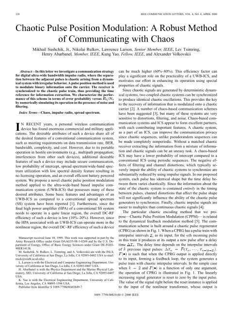
The particular chaotic encoding <strong>method</strong> that we propose—<strong>Chaotic</strong><br />
Pulse Position Modulation (CPPM)— is related<br />
to the dynamical feedback <strong>modulation</strong> <strong>method</strong> [5]. The communication<br />
scheme is built around a chaotic <strong>pulse</strong> regenerator<br />
(CPRG) as shown in Fig. 1. When a CPRG has a <strong>pulse</strong> train with<br />
inter<strong>pulse</strong> intervals as its input, for the th incoming <strong>pulse</strong><br />
in this train it produces at its output a new <strong>pulse</strong> after a delay<br />
time . The delay time depends on the inter<strong>pulse</strong> intervals<br />
<strong>of</strong> previous input <strong>pulse</strong>s: .<br />
is such that when the CPRG output is applied directly<br />
to its input, forming a feedback loop, the system generates a<br />
<strong>pulse</strong> train with chaotic inter<strong>pulse</strong> intervals. In the simple case<br />
when and is a function <strong>of</strong> only one argument,<br />
the operation <strong>of</strong> CPRG is illustrated in Fig. 1. The linearly<br />
increasing signal generator is reset to zero by the input <strong>pulse</strong>.<br />
The value <strong>of</strong> the signal right before the reset instance is applied<br />
to the input <strong>of</strong> the nonlinear transformer, whose output is
Fig. 1. Illustration <strong>of</strong> the basics <strong>of</strong> CPPM schemes and CPRG operation.<br />
stored in the sample-and-hold circuit. When the output <strong>of</strong> the<br />
linearly increasing signal generator reaches the value stored in<br />
the sample-and-hold circuit, a <strong>pulse</strong> is produced at the output<br />
<strong>of</strong> the CPRG. With a proper choice <strong>of</strong> the system will<br />
spontaneously generate chaotic <strong>pulse</strong> trains, when the CPRG<br />
output is applied to its input. An example <strong>of</strong> such chaotic<br />
system can be found in [4].<br />
In our scheme the binary information is applied to the <strong>pulse</strong><br />
train at the output <strong>of</strong> the CPRG by adding a block in the<br />
feedback loop that leaves the signal unchanged, if “0” is being<br />
transmitted, or delays the <strong>pulse</strong> by a fixed time if “1” is being<br />
transmitted. This modulated <strong>pulse</strong> sequence is the transmitted<br />
signal. If an unauthorized receiver has no information on<br />
the spacing between the <strong>pulse</strong>s leaving the CPRG, it cannot<br />
determine whether a particular received <strong>pulse</strong> was delayed, and<br />
thus whether “0” or “1” was transmitted. At the receiver side,<br />
the signal is applied to the input <strong>of</strong> an identical CPRG, so the<br />
outputs from the CPRG’s in the transmitter and the receiver are<br />
identical. Thus the signal at the output <strong>of</strong> the receiver CPRG is<br />
identical to the signal in the channel, except some <strong>pulse</strong>s in the<br />
transmitted signal are delayed by the information <strong>modulation</strong>.<br />
By evaluating the relative <strong>pulse</strong> timings in the received signal<br />
and in the signal at the output <strong>of</strong> the CPRG, the receiver can<br />
recover the digital message. When the CPRG’s are not matched<br />
with sufficient precision, a large decoding error results. Thus<br />
the parameters <strong>of</strong> the CPRG’s act like a privacy key.<br />
When synchronized, the receiver “knows” the time interval<br />
or a window where it can expect a <strong>pulse</strong> corresponding to “1”<br />
or “0.” This allows the input to be blocked at all times except<br />
when a <strong>pulse</strong> is expected. The time intervals when the input to<br />
a particular receiver is blocked can be utilized by other users.<br />
To decode a bit <strong>of</strong> information we must determine whether a<br />
<strong>pulse</strong> from the transmitter falls into the window corresponding<br />
to “0” or that corresponding to “1,” which can be done by integrating<br />
the input signal within the windows around the expected<br />
locations <strong>of</strong> <strong>pulse</strong>s corresponding to “0” and to “1.” Under the<br />
ideal condition <strong>of</strong> perfect time and polarity synchronizations,<br />
performance <strong>of</strong> the CPPM system (denoted by the “Ideal<br />
PPM” curve) is known to be 3 dB worse than the BPSK system<br />
[6] as shown in Fig. 2. This performance is achieved with the<br />
window size equal to the <strong>pulse</strong> duration. In the case <strong>of</strong> imperfect<br />
synchronization the window cannot be so narrow, and with the<br />
Fig. 2. Error probabilities <strong>of</strong> ideal BPSK, PPM, and noncoherent FSK systems<br />
compared to the simulated proposed CPPM systems.<br />
Fig. 3. Diagram <strong>of</strong> the receiver.<br />
129<br />
larger window size and the same detection <strong>method</strong> we shall have<br />
an additional performance loss equal to dB where<br />
is the window size and is the <strong>pulse</strong> duration. The ideal noncoherent<br />
binary FSK system performance is also shown in Fig. 2<br />
for comparison.<br />
We evaluated the performance <strong>of</strong> CPPM by numerically simulating<br />
its real-time implementation. The transmitter generates<br />
the <strong>pulse</strong> train with separation between the <strong>pulse</strong>s proportional<br />
to . The sequence is generated by the modulated tent map,<br />
with , where is the<br />
binary information signal.<br />
The proposed CPPM receiver block diagram is shown in<br />
Fig. 3. 1 Based on the state <strong>of</strong> the synchronized CPRG, the<br />
input is blocked at all times except the time windows around<br />
the expected locations <strong>of</strong> the <strong>pulse</strong>s corresponding to “1” and<br />
“0.” The signals within these windows are applied to two<br />
peak detectors (PD). Based on which window contained the<br />
peak <strong>of</strong> the maximum height, we decide whether “1” or “0”<br />
was transmitted and the signal within the corresponding time<br />
window is passed to the receiver CPRG. Details concerning<br />
the real-time implementation <strong>of</strong> this scheme will be described<br />
elsewhere.<br />
The channel and transmitter and receiver operations are<br />
modeled by adding WGN to the output <strong>of</strong> the transmitter<br />
and then LP-filtering the signal with a FIR filter. We measure<br />
SNR and find using the following formula [7]:<br />
, where is the SNR, is the<br />
channel bandwidth and is the bit rate.<br />
1 We have considered a few receiver designs. The design presented here contains<br />
an extra feedback loop, which improves the performance.
130 IEEE COMMUNICATION LETTERS, VOL. 4, NO. 4, APRIL 2000<br />
In our simulations we used the following parameters: the<br />
<strong>pulse</strong> duration was 100 ps, the <strong>modulation</strong> amplitude, 400 ps,<br />
and the window size 400 ps. The filter cut-<strong>of</strong>f was at 5 GHz.<br />
The threshold was set at half the <strong>pulse</strong> peak voltage. The<br />
average bit rate was 0.5 Gb/s with the average inter-<strong>pulse</strong><br />
distance 2 ns. The distance between the <strong>pulse</strong>s would vary by<br />
as much as 50% from the average.<br />
The performance curve corresponding to these parameters is<br />
shown in Fig. 2. One can see that CPPM performs in simulations<br />
5 dB worse than the ideal PPM system. This is primarily due to<br />
the fact that it is difficult to maintain perfect synchronization<br />
for chaotic systems. In particular, to use convolution detection,<br />
the synchronization error should be less than the <strong>pulse</strong> duration.<br />
We found that with the synchronization errors that we typically<br />
encountered in our system, decoding based on peak detectors<br />
performs better.<br />
Although the CPPM performance is not as good as that <strong>of</strong><br />
noncoherent FSK and BPSK, the power efficiency <strong>of</strong> HPA’s<br />
used in im<strong>pulse</strong> transmission makes this system competitive and<br />
places it well within the range that is acceptable in practical<br />
applications. At the expense <strong>of</strong> the performance loss, CPPM<br />
improves communication privacy, spectral characteristics and<br />
detection resistance compared to conventional im<strong>pulse</strong> communications.<br />
From the electronics design point <strong>of</strong> view, incor-<br />
porating these features using chaos does not lead to a significant<br />
increase in design complexity or power consumption. As a<br />
number <strong>of</strong> improvements to CPPM are currently being studied,<br />
to the best <strong>of</strong> our knowledge, CPPM already performs extremely<br />
well, compared to other chaos-based communication systems.<br />
This makes CPPM a prime candidate for the development <strong>of</strong><br />
practical chaos-based covert spread spectrum systems.<br />
REFERENCES<br />
[1] M. Z. Win and R. A. Scholtz, “Im<strong>pulse</strong> radio: How it works.,” IEEE<br />
Commun. Lett., vol. 2, pp. 36–8, Feb. 1998.<br />
[2] C. W. Wu and L. O. Chua, “A simple way to synchronize chaotic systems<br />
with applications to secure communication systems,” Int. J. Bifurc.<br />
Chaos, vol. 3, no. 6, pp. 1619–1627, 1993.<br />
[3] M. Hasler, “Synchronization <strong>of</strong> chaotic systems and transmission <strong>of</strong> information,”<br />
Int. J. Bifurc. Chaos, vol. 8, no. 4, pp. 647–659, 1998.<br />
[4] H. Torikai, T. Saito, and W. Schwarz, “Multiplex communication<br />
scheme based on synchronization via multiplex <strong>pulse</strong>-trains,” in Proc.<br />
1998 IEEE Int. Symp. on Circuits and Systems, 1998, pp. 554–557.<br />
[5] A. R. Volkovskii and N. F. Rul’kov, “Synchronous chaotic response <strong>of</strong> a<br />
nonlinear oscillator system as a principle for the detection <strong>of</strong> the information<br />
component <strong>of</strong> chaos,” Sov. Tech. Phys. Lett., vol. 19, pp. 97–99,<br />
1993.<br />
[6] R. M. Gargliardi, Introduction to Communications Engineering. New<br />
York: Wiley, 1988.<br />
[7] B. Sklar, Digital Communications: Fundamentals and Aplications.<br />
Englewood Cliffs, NJ: Prentice Hall, 1988.