Fracture Toughness
Fracture Toughness
Fracture Toughness

You also want an ePaper? Increase the reach of your titles
YUMPU automatically turns print PDFs into web optimized ePapers that Google loves.
<strong>Fracture</strong> <strong>Toughness</strong><br />
Home - Education Resources - NDT Course Material - Materials and Processes<br />
<strong>Fracture</strong> <strong>Toughness</strong><br />
<strong>Fracture</strong> toughness is an indication of the amount of stress required to propagate a<br />
preexisting flaw. It is a very important material property since the occurrence of flaws is<br />
not completely avoidable in the processing, fabrication, or service of a<br />
material/component. Flaws may appear as cracks, voids, metallurgical inclusions, weld<br />
defects, design discontinuities, or some combination thereof. Since engineers can never<br />
be totally sure that a material is flaw free, it is common practice to assume that a flaw of<br />
some chosen size will be present in some number of components and use the linear<br />
elastic fracture mechanics (LEFM) approach to design critical components. This<br />
approach uses the flaw size and features, component geometry, loading conditions and<br />
the material property called fracture toughness to evaluate the ability of a component<br />
containing a flaw to resist fracture.<br />
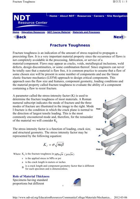
A parameter called the stress-intensity factor (K) is used to<br />
determine the fracture toughness of most materials. A Roman<br />
numeral subscript indicates the mode of fracture and the three<br />
modes of fracture are illustrated in the image to the right. Mode<br />
I fracture is the condition in which the crack plane is normal to<br />
the direction of largest tensile loading. This is the most<br />
commonly encountered mode and, therefore, for the remainder<br />
of the material we will consider K I<br />
The stress intensity factor is a function of loading, crack size,<br />
and structural geometry. The stress intensity factor may be<br />
represented by the following equation:<br />
Where: K I is the fracture toughness in<br />
s is the applied stress in MPa or psi<br />
a is the crack length in meters or inches<br />
is a crack length and component geometry factor that is different<br />
B<br />
for each specimen and is dimensionless.<br />
Role of Material Thickness<br />
Specimens having standard<br />
proportions but different<br />
http://www.ndt-ed.org/EducationResources/CommunityCollege/Materials/Mechanica...<br />
페이지 1 / 5<br />
2012-03-06
<strong>Fracture</strong> <strong>Toughness</strong><br />
absolute size produce different<br />
values for KI . This results because the stress states adjacent to the flaw changes with the<br />
specimen thickness (B) until the thickness exceeds some critical dimension. Once the<br />
thickness exceeds the critical dimension, the value of KI becomes relatively constant and<br />
this value, KIC , is a true material property which is called the plane-strain fracture<br />
toughness. The relationship between stress intensity, KI , and fracture toughness, KIC , is<br />
similar to the relationship between stress and tensile stress. The stress intensity, KI ,<br />
represents the level of “stress” at the tip of the crack and the fracture toughness, KIC , is<br />
the highest value of stress intensity that a material under very specific (plane-strain)<br />
conditions that a material can withstand without fracture. As the stress intensity factor<br />
reaches the KIC value, unstable fracture occurs. As with a material’s other mechanical<br />
properties, K IC is commonly reported in reference books and other sources.<br />
Plane-Strain and Plane-Stress<br />
When a material with a crack is loaded in tension, the<br />
materials develop plastic strains as the yield stress is exceeded<br />
in the region near the crack tip. Material within the crack tip<br />
stress field, situated close to a free surface, can deform<br />
laterally (in the z-direction of the image) because there can be<br />
no stresses normal to the free surface. The state of stress tends<br />
to biaxial and the material fractures in a characteristic ductile<br />
manner, with a 45 o shear lip being formed at each free<br />
surface. This condition is called “plane-stress" and it occurs in<br />
relatively thin bodies where the stress through the thickness<br />
cannot vary appreciably due to the thin section.<br />
However, material away<br />
from the free surfaces of a<br />
relatively thick<br />
component is not free to<br />
deform laterally as it is<br />
constrained by the<br />
surrounding material. The<br />
stress state under these<br />
conditions tends to<br />
triaxial and there is zero<br />
strain perpendicular to<br />
both the stress axis and<br />
the direction of crack<br />
propagation when a<br />
material is loaded in<br />
tension. This condition is<br />
called “plane-strain” and<br />
페이지 2 / 5<br />
Plane Strain - a condition of<br />
a body in which the<br />
displacements of all points in<br />
the body are parallel to a<br />
given plane, and the values of<br />
theses displacements do not<br />
depend on the distance<br />
perpendicular to the plane<br />
Plane Stress – a condition of<br />
a body in which the state of<br />
stress is such that two of the<br />
principal stresses are always<br />
parallel to a given plane and<br />
are constant in the normal<br />
direction.<br />
http://www.ndt-ed.org/EducationResources/CommunityCollege/Materials/Mechanica...<br />
2012-03-06
<strong>Fracture</strong> <strong>Toughness</strong><br />
is found in thick plates.<br />
Under plane-strain conditions, materials behave essentially elastic until the fracture stress<br />
is reached and then rapid fracture occurs. Since little or no plastic deformation is noted,<br />
this mode fracture is termed brittle fracture.<br />
Plane-Strain <strong>Fracture</strong> <strong>Toughness</strong> Testing<br />
When performing a fracture toughness test, the most<br />
common test specimen configurations are the single edge<br />
notch bend (SENB or three-point bend), and the compact<br />
tension (CT) specimens. From the above discussion, it is<br />
clear that an accurate determination of the plane-strain<br />
fracture toughness requires a specimen whose thickness<br />
exceeds some critical thickness (B). Testing has shown<br />
that plane-strain conditions generally prevail when:<br />
Where: B<br />
is the minimum thickness that produces a condition where<br />
plastic strain energy at the crack tip in minimal<br />
K IC is the fracture toughness of the material<br />
s y is the yield stress of material<br />
페이지 3 / 5<br />
When a material of unknown fracture toughness is tested, a specimen of full material<br />
section thickness is tested or the specimen is sized based on a prediction of the fracture<br />
toughness. If the fracture toughness value resulting from the test does not satisfy the<br />
requirement of the above equation, the test must be repeated using a thicker specimen. In<br />
addition to this thickness calculation, test specifications have several other requirements<br />
that must be met (such as the size of the shear lips) before a test can be said to have<br />
resulted in a K IC value.<br />
When a test fails to meet the thickness and other test requirement that are in place to<br />
insure plane-strain condition, the fracture toughness values produced is given the<br />
designation KC . Sometimes it is not possible to produce a specimen that meets the<br />
thickness requirement. For example when a relatively thin plate product with high<br />
toughness is being tested, it might not be possible to produce a thicker specimen with<br />
plain-strain conditions at the crack tip.<br />
Plane-Stress and Transitional-Stress States<br />
For cases where the plastic energy at the crack tip is not negligible, other fracture<br />
mechanics parameters, such as the J integral or R-curve, can be used to characterize a<br />
material. The toughness data produced by these other tests will be dependant on the<br />
thickness of the product tested and will not be a true material property. However, plane-<br />
http://www.ndt-ed.org/EducationResources/CommunityCollege/Materials/Mechanica...<br />
2012-03-06
<strong>Fracture</strong> <strong>Toughness</strong><br />
strain conditions do not exist in all structural configurations and using KIC values in the<br />
design of relatively thin areas may result in excess conservatism and a weight or cost<br />
penalty. In cases where the actual stress state is plane-stress or, more generally, some<br />
intermediate- or transitional-stress state, it is more appropriate to use J integral or Rcurve<br />
data, which account for slow, stable fracture (ductile tearing) rather than rapid<br />
(brittle) fracture.<br />
Uses of Plane-Strain <strong>Fracture</strong> <strong>Toughness</strong><br />
KIC values are used to determine the critical crack length when a given stress is applied<br />
to a component.<br />
Where: s c<br />
is the critical applied stress that will cause failure<br />
K IC is the plane-strain fracture toughness<br />
Y is a constant related to the sample's geometry<br />
is the crack length for edge cracks<br />
a<br />
or one half crack length for internal crack<br />
KIC values are used also used to calculate the critical stress value when a crack of a given<br />
length is found in a component.<br />
is the crack length for edge cracks<br />
Where: a<br />
or one half crack length for internal crack<br />
s is the stress applied to the material<br />
K IC is the plane-strain fracture toughness<br />
Y is a constant related to the sample's geometry<br />
페이지 4 / 5<br />
Orientation<br />
The fracture toughness of a material commonly varies with grain direction. Therefore, it<br />
is customary to specify specimen and crack orientations by an ordered pair of grain<br />
direction symbols. The first letter designates the grain direction normal to the crack<br />
plane. The second letter designates the grain direction parallel to the fracture plane. For<br />
flat sections of various products, e.g., plate, extrusions, forgings, etc., in which the three<br />
grain directions are designated (L) longitudinal, (T) transverse, and (S) short transverse,<br />
the six principal fracture path directions are: L-T, L-S, T-L, T-S, S-L and S-T.<br />
http://www.ndt-ed.org/EducationResources/CommunityCollege/Materials/Mechanica...<br />
2012-03-06
<strong>Fracture</strong> <strong>Toughness</strong><br />
http://www.ndt-ed.org/EducationResources/CommunityCollege/Materials/Mechanica...<br />
페이지 5 / 5<br />
2012-03-06