F-35 Joint Strike Fighter (JSF)
F-35 Joint Strike Fighter (JSF)
F-35 Joint Strike Fighter (JSF)

Create successful ePaper yourself
Turn your PDF publications into a flip-book with our unique Google optimized e-Paper software.
F-<strong>35</strong> <strong>Joint</strong> <strong>Strike</strong> <strong>Fighter</strong> (<strong>JSF</strong>)<br />
Executive Summary<br />
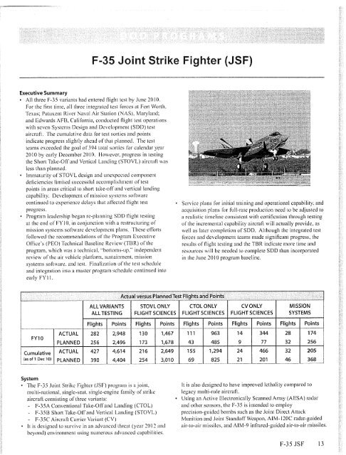
• All three F-<strong>35</strong> variants had entered flight test by June 2010.<br />
For the first time, all three integrated test forces at Fort Worth,<br />
Texas; Patuxent River Naval Air Station (NAS), Maryland;<br />
and Edwards AFB, California, conducted flight test operations<br />
with seven Systems Design and Development (SDD) test<br />
aircraft. The cumulative data for test sorties and points<br />
indicate progress slightly ahead of that planned. The test<br />
teams exceeded the goal of 39.4 total sorties for calendar year<br />
2010 by early December 2010. However, progress in testing<br />
the Short Take-Off and Vertical Landing (STOVL) aircraft was<br />
less than planned.<br />
• Immaturity of STOVL design and unexpected component<br />
deficiencies limited successful accomplishment of test<br />
points in areas critical to short take-off and vertical landing<br />
capability. Development of mission systems software<br />
continued to experience delays that affected flight test<br />
progress.<br />
• Program leadership began re-planning SDD flight testing<br />
at the end of FY 10, in conjunction with a restructuring of<br />
mission systems soil are development plans. These efforts<br />
followed the recommendations of the Program Executive<br />
Offices (PEO) Technical Baseline Review (TBR) Of the<br />
program, which was a technical. "bottoms-up," independent<br />
review of the air vehicle platform, sustainment, mission<br />
systems software. and test. Finalization of the test schedule<br />
and integration into a master program schedule continued into<br />
early FY II.<br />
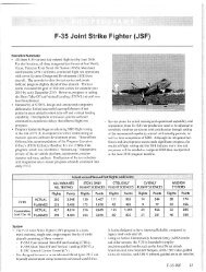
FY10<br />
ALL VARIANTS<br />
ALL TESTING<br />
Actual versus Planned Test Flights and Points<br />
SToVL ONLY<br />
FLIGHT SCIENCES<br />
• Service plans for initial training and operational capability. and<br />
acquisition plans for full-rate production need to be adjusted to<br />
a realistic timeline consistent with certification through testing<br />
of the incremental capability aircraft will actually provide, as<br />
well as later completion of SDD. Although the integrated test<br />
forces and development teams made significant progress, the<br />
results of flight testing and the TBR indicate more time and<br />
resources will be needed to complete SDD than incorporated<br />
in the June 2010 program baseline.<br />
CToL oNLY<br />
FLIGHT SCIENCES<br />
CV ONLY<br />
FLIGHT SCIENCES<br />
MISSION<br />
SYSTEMS<br />
Flights Points Flights Polnts Flights Points Flights Points Flights Points<br />
ACTUAL 282 2,948 130 1,467 111 963 14 344 28 174<br />
PLANNED 256 2,496 173 1,678 43 485 9 77 32 256<br />
Cumulative ACTUAL 427 4,614 216 2,649 155 1,294 24 466 32 205<br />
(as of 1 Dec 10) PLANNED 390 4,404 254 3,010 69 825 21 201 46 368<br />
System<br />
• The F-<strong>35</strong> <strong>Joint</strong> <strong>Strike</strong> <strong>Fighter</strong> (<strong>JSF</strong>) program is a joint,<br />
multi-national, single-seat, single-engine family of strike<br />
aircraft consisting of three variants:<br />
- F-<strong>35</strong>A Conventional Take-Off and Landing (CTOL)<br />
- F-<strong>35</strong>B Short Take-Off and Vertical Landing (STOVL)<br />
- F-<strong>35</strong>C Aircraft Carrier Variant (CV)<br />
• It is designed to survive in an advanced threat (year 2012 and<br />
beyond) environment using numerous advanced capabilities.<br />
It is also designed to have improved lethality compared to<br />
legacy multi-role aircraft.<br />
• Using an Active Electronically Scanned Array (AESA) radar<br />
and other sensors, the F-<strong>35</strong> is intended to employ<br />
precision-guided bombs such as the <strong>Joint</strong> Direct Attack<br />
Munition and <strong>Joint</strong> Standoff Weapon, AIM-120C radar-guided<br />
air-to-air missiles, and AIM-9 infrared-guided air-to-air missiles.<br />
F-<strong>35</strong> <strong>JSF</strong> 13
The program incrementally provides mission capability:<br />
Block 1 (initial . ), Block 2 (advanced), Block 3 (full).<br />
• The F-<strong>35</strong> is under development by a partnership of countries:<br />
the United States. Great Britain, Italy, the Netherlands, Turkey.<br />
Canada, Australia, Denmark, and Norway,<br />
Mission<br />
• A force equipped with F-<strong>35</strong> units should permit the Combatant<br />
Commander to attack targets day or night, in all weather, in<br />
highly defended areas of joint operations.<br />
Activity<br />
Activity Affecting Test Strategy, Planning, and Resourcing<br />
<strong>Joint</strong> Estimate Team 11<br />
• The second independent joint Estimate Team (JET)<br />
review concluded last year that the SDD flight test plan<br />
lacked sufficient resources and incorporated unrealistic<br />
assumptions for flight test productivity relative to historical<br />
experience. At the time of the JET II review, the program<br />
had accomplished approximately 25 flight test hours on<br />
only two STOVL SDD test aircraft; no aircraft had ferried<br />
to the Hight test centers. .<br />
• In early FY 10, the program began the process of<br />
incorporating the review's key recommendations: adding<br />
test aircraft to the SDI) test fleets from production<br />
lots, adding down-time for aircraft maintenance and<br />
modifications, reducing the assumed productivity of certain<br />
flight test aircraft, increasing anti extending engineering and<br />
test operations staffs to support concurrent development<br />
and test, and adding an additional software integration<br />
and test lab. The program was also directed to implement<br />
recommendations of the first Independent Manufacturing<br />
Review Team, to include reducing production in the Future<br />
Years Defense Plan by 122 aircraft, thereby reducing<br />
concurrency of development and production.<br />
• These reviews and actions, along with a review of cost<br />
and risk in development of the propulsion system, fed to<br />
the acknowledgement of a breach of the Nunn-McCurdy<br />
"critical" cost thresholds for the <strong>JSF</strong> program.<br />
Nunn-McCurdy Certification<br />
• An Integrated Test Review occurred in April to support.<br />
the Nunn-McCurdy certification. Representatives from<br />
the Edwards and Patuxent River flight test centers. .ISF<br />
Operational Test Team, and the Services conducted the<br />
review and identified numerous issues affecting the<br />
executability of the flight test schedule.<br />
• The Nunn-McCurdy program certification occurred in<br />
June. At the time of the certification of the new program<br />
budget baseline, the flight test program had accomplished<br />
approximately J90 flight test hours and ferried five total<br />
aircraft to the test centers, including two CTOL flight<br />
sciences aircraft, with an overall average number of 3.2<br />
months on-site at the flight test centers. Low fly rates<br />
14 F-<strong>35</strong> <strong>JSF</strong><br />
• Targets include fixed and mobile land targets, enemy surface<br />
units at sea, and air threats, including advanced cruise missiles.<br />
Major Contract&<br />
Lockheed Martin, Aeronautics Division. Advanced Development<br />
Programs Fort Worth. Texas<br />
on STOVL flight sciences aircraft and unanticipated<br />
deficiencies in the design had begun to emerge in flight<br />
test. Analysis during the review indicated STOVL flight<br />
sciences was becoming the critical path to complete SDI)<br />
flight test. The program acknowledged later ferry dates for<br />
remaining SDD test aircraft. The estimate of SDD flight<br />
test completion was extended to July 2015.<br />
Technical Baseline Review (MR)<br />
• The new FED commissioned a TBR of the program in June<br />
to determine the technical adequacy or program plans and<br />
resources. The TBR benefited from more flight test results<br />
than previous reviews because the three Integrated Test<br />
Force sites had accumulated over 440 flight test hours and<br />
the overall average in months on-site for SDD aircraft at<br />
the flight test centers Was 72 months, However, during the<br />
months since the last program review, more problems with<br />
STOVL design and mission systems software arose.<br />
The TBR recommended further changes to the parameters<br />
used to plan and model flight test schedules, as well as<br />
numerous changes in staffing and other resources needed<br />
to complete SDI) and enter lOT&E. Specific changes<br />
to the schedule recommended by the TBR include lower<br />
flight rates for test aircraft that are tailored to each variant<br />
(lower than prior independent reviews), additional re-fly<br />
and regression sorties that are tailored to the type of testing,<br />
and more flight test sorties. The TBR also determined more<br />
time was needed for completion of all remaining software<br />
increments. The result is a completion of developmental<br />
flight test in late 2016, with STOVL fligh t sciences<br />
completing later than the other two variants.<br />
F-<strong>35</strong> Flight Test<br />
STOVL Flight Sciences, Flight Test with BF-1 BF-2, and<br />
BF-3 Test Aircraft<br />
• BF-3 ferried to Patuxent River NAS, Maryland, in February<br />
2010; it is the last of three B-model flight sciences aircraft.<br />
• Maintenance, test operations, and engineering, staffs<br />
increased significantly (approximately 25 percent) in FY10<br />
at Patuxent River, NAS. The program intends to reach full<br />
strength in 2011, pending hiring of qualified contractor<br />
personnel.
• The government-contractor test team attempted test points<br />
in up-and-away flight envelope expansion. STOVL-mode<br />
flight, handling qualities, propulsion testing and readiness<br />
for the first ship integration test period (planned for<br />
late 2011).<br />
• In FY 10. STOVE Flight Sciences aircraft flew 130 of 173<br />
planned sorties; the test team completed 1,467 of l,678<br />
planned test points. However, the test team accomplished<br />
only 10 of 42 planned vertical landings between March and<br />
November 2010; these are key to the shore-based build-up<br />
to testing on L-class amphibious ships at sea, In the first<br />
two months of FYI l, STOVE flight sciences aircraft flew<br />
54 sorties. 5 more than planned; the test team accomplished<br />
<strong>35</strong>6 of 506 planned test points, From mid-August<br />
until early November, the test team flew CTOL-mode<br />
configurations due to limitations of the vertical-lift<br />
capability of the STOVL system. STOVE-mode flight test<br />
operations began again in BF-1 in November 2010,<br />
• In July, the program made changes to supply chain<br />
management to provide timely spares and implemented<br />
surge scheduling and 7-day/week maintenance operations,<br />
These actions contributed to an increase in flights per month<br />
of approximately 25 percent.<br />
• Discoveries during STOVL Flight Sciences testing this<br />
fiscal year include transonic wing roll-off, greater than<br />
expected sideslip during medium angle-of-attack testing,<br />
higher and unanticipated structural loads on STOVL doors,<br />
and poor reliability and maintainability of key components.<br />
CTOL Hight Sciences, night Test with AF-1 and A F-2 Test<br />
Aircraft<br />
• AF-1 and AF-2 ferried to Edwards AFB. California, in May.<br />
as planned.<br />
• Maintenance, test operations, and engineering staffs<br />
increased significantly (approximately 50 percent) in FY10.<br />
The program intends to reach full strength in 2011, pending<br />
hiring of qualified contractor personnel.<br />
• In FY 10, the test team made progress in envelope<br />
expansion, handling qualities, and propulsion test points.<br />
CTOL Flight Sciences aircraft flew 111 sorties, 6$ more<br />
than planned. The test team completed 963 test points,<br />
exceeding the 485 planned flight test points for the fiscal<br />
year. In the first two months of FY11, CTOL flight sciences<br />
aircraft flew 44 sorties, 18 more than planned; the test team<br />
accomplished 331 4340 planned test points.<br />
• The program anticipates the remaining CTOL Flight<br />
Sciences aircraft, AF-4, will ferry to Edwards, AFB,<br />
California. by January 2011, approximately two months<br />
later than planned.<br />
• Discoveries during CTOL flight sciences flight test in this<br />
fiscal year include transonic wing roll-off, greater than<br />
expected sideslip during medium angle-of-attack testing,<br />
and problems with reliability and maintainability of key<br />
components.<br />
CV Flight Sciences, Flight Test with CF-1 Test Aircraft<br />
CF- I flew for the first time in June 2010. The aircraft<br />
ferried to Patuxent River NAS, Maryland, in early<br />
November 2010, one month later than planned.<br />
• While at Fort Worth. Texas, CF- 1 flew airworthiness<br />
and initial-service-release propulsion system test flights,<br />
accomplishing 14 flight test sorties, five more than planned.<br />
As a result, CF-1. flew 344 test points, significantly more<br />
than the 77 planned for the fiscal year. In the first two<br />
months of FY II. aircraft CF-1 flew 10 of 12 planned<br />
sorties; the test team accomplished 4 of 14 planned test<br />
points.<br />
• The Integrated Test Force at Patuxent River NAS,<br />
Maryland, built up maintenance and engineering support<br />
personnel in anticipation of the arrival of CF-1, which the<br />
program delivered to the test center in November 2010.<br />
• The program anticipates the remaining CV flight<br />
sciences test aircraft, CF-2 and CF-5. will ferry to<br />
Patuxent River NAS. Maryland, in February 2011 and<br />
late 2013. respectively. Aircraft CF-2 would then arrive<br />
approximately two months later than planned.<br />
Mission Systems, 13F-4 and A F-3 Right Tests and Software<br />
Development Progress<br />
• Block 0.5 Infrastructure<br />
- The program released Block 0.5 software for flight<br />
test in March 2010, five months later than planned.<br />
The software had completed mission systems lab<br />
integration activity and integration flights on the<br />
Cooperative Avionics Test Bed (CATB). Block 0.5<br />
is the infrastructure increment, which contains<br />
communications, navigation, and limited radar<br />
functionality.<br />
Aircraft BF-4, loaded with Block 0.5, accomplished first<br />
flight in April 2010, five months later than planned, and<br />
then ferried to Patuxent River NAS, Maryland, in June,<br />
two months later than planned, and began Block 0.5<br />
flight test.<br />
Test teams attempted approximately 70 percent of the<br />
planned Block 0.5 flight test points on BF-4. Software<br />
problems occurring before and during flight test were<br />
not resolved in the Block 0,5 configuration. Program<br />
leadership deemed Block 0.5 unsuitable for initial<br />
training and adjusted the software development plan to<br />
implement fixes for the Block 0.5 problems in the initial<br />
release of Block flle integrated test force is re-flying<br />
selected Block 0.5 flight test points in the Block 1<br />
configuration.<br />
• Block I, Initial Training Capability<br />
- The program delivered aircraft AF-3 in a Block 1<br />
configuration to Edwards AFB, California, in December<br />
2010, approximately five months later than planned.<br />
- The program intends the Block I design (which includes<br />
multi-sensor fusion capability) to support the initial<br />
F-<strong>35</strong> <strong>JSF</strong> 15
training, syllabus for the initial cadres at the training<br />
center. The development team conducted integration<br />
activity with an initial version of Block 1, including fixes<br />
to Block 0.5 problems. in the mission systems labs and<br />
on the CATB,<br />
The program planned to release the first Block J<br />
increment to flight test aircraft in August 2010, but. F-<strong>35</strong><br />
flight testing did not begin until November 2010. By<br />
the end of November. the test team flew 4 of 14 planned<br />
sorties and accomplished 31 of 112 test points.<br />
• Block 2 and Block 3 Software Development Progress<br />
The Block 2 detailed flight test planning process began<br />
in September 2010.<br />
In August, the program began re-planning the software<br />
development schedule for completing and certifying<br />
Block 1, Block 2, and Block 3 increments of SDD<br />
capabi 1 ity,<br />
• Ferry of Remaining SDD Mission Systems Flight Test<br />
Aircraft<br />
- The program anticipates ferry of BF-5 in late March<br />
2011 and CF-3 in May 2011: these deliveries to the test<br />
centers arc approximately four and five months later than<br />
planned, respectively.<br />
Modeling and Simulation<br />
Verification Simulation (VSIM)<br />
• The program commenced planning of validation efforts<br />
for F-<strong>35</strong> modeling, development of the virtual battlespace<br />
environment, and integration of the two into one simulation<br />
intended for developmental test and evaluation.<br />
• The program identified funding shortfalls for the<br />
Verification Simulation (VSIM) to meet OT&.E needs,<br />
primarily in the battlespace environment, and provided data<br />
for an independent cost assessment leading to inclusion of<br />
VSIM costs in the program baseline. The Services have<br />
been directed to fully fund VSIM for OT&E.<br />
• The PEO completed a VSIM Sufficiency Review to<br />
determine the means to provide the required OT&E VSIM<br />
capability.<br />
Oilier Models and Corporate Labs<br />
• The program continues to plan to accredit a total of 32<br />
models and virtual laboratories for use as test venues<br />
(including VSIM) in developmental testing. The program<br />
planned to accredit 11 models by the end of FY 10;<br />
however, the program office accredited only three venues<br />
by September 2010.<br />
• Due to software development delays and shifts in capability<br />
to later software blocks, the program decided several<br />
models are not needed to support testing of Block 1 mission<br />
systemic.<br />
Static Structural and Durability Testing<br />
• The test teams completed STOVL and CTOL static structural<br />
testing ahead of schedule, which is an important input to<br />
envelope expansion through flight test. The CV static test<br />
article completed initial drop tests for carrier suitability.<br />
16 F-<strong>35</strong> <strong>JSF</strong><br />
• CTOL and STOVL durability testing began in FY10. Results<br />
for a loading, equivalent to one aircraft lifetime (8,000 hours)<br />
were expected in mid-FY11 for the STOVL aircraft and early<br />
FY 12 for the CTOL aircraft, However, a major fatigue crack<br />
was found in the STOVE test article at approximately 1,500<br />
flight hours. Failure of the bulkhead in flight would have<br />
safety of flight consequences. The program stopped fatigue<br />
testing on both the STOVL and CTOL test articles and<br />
began root cause analysis in November 2010. The STOVL<br />
bulkhead is constructed of aluminum alloy. The CTOL and<br />
CV bulkheads have a similar but not identical design and are<br />
made of titanium, The difference in bulkhead material is due<br />
to actions taken several years ago to reduce the weight of the<br />
STOVL aircraft<br />
Propulsion System Testing<br />
• F1<strong>35</strong>. The program delivered the first initial-service-release<br />
Fl<strong>35</strong> engines to SDD CV and STOVL test aircraft. By the<br />
end of November 2010, CF-1 had flown 36 flight hours with<br />
this engine; however, BF-5 had not yet flown. The program<br />
began implementing plans to modify test aircraft to rectify<br />
the afterburner "screech" problem, a problem that prevents<br />
the engine from sustaining full thrust. These modifications<br />
are necessary for the test aircraft to complete envelope<br />
expansion at the planned tempo.<br />
• 1=136. Engine testing accomplished approximately 430 of<br />
739 planned ground test hours by the end of the fiscal year.<br />
The program is examining ways to accelerate testing in order<br />
to meet the !planned start of flight test with the Fl 36 in late<br />
2011 for CTOL, and late 2012 for STOVL.<br />
Operational Test and Evaluation<br />
• In June, the <strong>JSF</strong> Operational Test. Team (JOTT) began<br />
OT-2E, the fifth operational assessment of progress towards<br />
developing an operationally effective and suitable Block 3<br />
mission capability in all three variants, The JOTT plans to<br />
complete this assessment in late 2011.<br />
• At the request of the <strong>JSF</strong> Program Executive Officer (PEG).<br />
the JOTT is also developing plans to assess the initial<br />
training capability intended for use with the first fleet pilots<br />
and maintenance crews in 2011,<br />
• The JOT. T reviewed and re-validated the November 2008<br />
requirements documentation for the VSIM for OT&E.<br />
DOTE approved the re-validated requirements.<br />
• The JOTT began the Readiness-to-Test evaluation process<br />
in FY 10, which uses an assessment template to determine<br />
actions necessary for the weapons system to be ready to<br />
successfully enter and complete the planned OT&E periods.<br />
This process identifies potential gaps between verification of<br />
contract specification compliance and delivery of the mission<br />
capability necessary to meet the operational requirements.<br />
• The JOTT significantly increased its work force and the<br />
Services identified pilots and maintenance crews for<br />
execution of early operational testing and assessments.
Air System-Ship Integration and Ship Suitability Testing<br />
• Coordination continued between the <strong>JSF</strong> program office,<br />
Naval Sea Systems Command, and Naval Air Systems<br />
Command offices responsible for planning and implementing<br />
actions to integrate the <strong>JSF</strong> aircraft and support systems<br />
on naval ships. The teams focused efforts on readiness for<br />
initial ship trial periods that the program now plans in late<br />
2011 (one year later than previously planned), as well as on<br />
planning the other actions needed to achieve initial operating<br />
capabilities of the B-model on L-class amphibious ships and<br />
the C-model on large-deck carriers.<br />
• The coordination teams are working significant issues in<br />
these areas: identification of personnel hazard zones around<br />
B-model aircraft, interoperability of the Autonomic Logistics<br />
Information System with Service and joint systems, carrier<br />
jet blast deflector modifications needed for CV aircraft<br />
operations, aircraft-ship connectivity for alignment of inertial<br />
navigation systems. secure facilities for handling special<br />
access material, and spectrum limitations.<br />
• The first ship trial period for the B-model STOVL aircraft<br />
has slipped from March 2011 to no earlier than late 2011 due<br />
to the slow flight test progress in accomplishing the shorebased<br />
build-up test points. The first C-model trial period on<br />
a large deck carrier is planned for early 2013.<br />
Live Fire Test and Evaluation<br />
• LFT&E conducted On-Board Inert Gus Generations System<br />
(OBIGGS) tests during FY09-FY10.<br />
• The Weapons Survivability Lab at China Lake took delivery<br />
of the Full-Up System-Level (FUSL) F-<strong>35</strong> aircraft. The<br />
aircraft is being prepared for ballistic testing. The test team<br />
will begin this testing in IQFY11.<br />
Assessment<br />
Test Schedule Re-Planning and Implementation of Changes<br />
• The year-long process of analyses during FY 10 (,1E111<br />
implementation. Nunn-McCurdy certification. and TBR)<br />
served to develop a more realistic estimate of SDD<br />
completion for Block 3 in all variants and identify steps<br />
to reduce risk in execution of the verification test and<br />
evaluation strategy. Although the sample size of experience<br />
with the CV is still small, the STOVL design emerged as the<br />
highest risk of all variants and the most difficult to progress<br />
through flight test. This is due in part to the difficulty in<br />
making progress in vertical lift operations compared to that<br />
planned. The analyses also revealed that the F-<strong>35</strong> mission<br />
systems software development and test is tending towards<br />
familiar historical patterns of extended development,<br />
discovery in flight test, and deferrals to later increments. The<br />
modifications recommended by the TBR (lower fly rates,<br />
more regression and re-fly margin, more nights, and other<br />
resource additions) that result in completion of SDD flight<br />
test for Block 3 in all three variants later than previously<br />
estimated are realistic and credible. Completion of STOVL<br />
flight sciences in this timeframe is dependent on whether<br />
or not the necessary changes to STOVL design can be<br />
implemented and tested. It will also depend on whether<br />
these changes result in fewer aircraft operating limitations<br />
and greater aircraft availability for test. The program will<br />
potentially need as much as a year longer than the other<br />
two variants to complete this variant's Right sciences and<br />
ship integration testing. The expectations approaching<br />
10 to 12 flight sciences sorties/month/aircraft in previous<br />
schedules are not achievable in the flight test program until<br />
changes are made to all variants that improve reliability<br />
and maintainability in flight test operations, Additionally,<br />
the process must begin to reduce the aircraft operating<br />
limitations, which inhibit flight test progress particularly in<br />
vertical lift STOVL testing.<br />
• Mission Systems flight test still contains significant<br />
uncertainty, which will affect any estimate of a Block 3<br />
completion date. This is primarily due to the delays<br />
incurred in development thus far and the filet that only the<br />
Block 0.5 flight test plan has actually been completed and<br />
approved. A test plan for Block 1 is currently in review<br />
by test center authorities, and the Block 2 test plan is in an<br />
initial draft state. Additionally, technical issues in the helmet<br />
mounted display and sensor fusion. along with uncertainties<br />
pertaining to new capabilities with which the program has<br />
limited experience on the F-<strong>35</strong> aircraft (multi-function<br />
advanced data link, distributed aperture system, infrared/<br />
electro-optical fused sensor tracks) are risks that affect<br />
the ability to accurately predict the conclusion of mission<br />
systems flight test. Completion by early 2016 is possible<br />
provided further delays in delivery of Block 2 and Block 3<br />
software are not incurred, and the program can overcome the<br />
helmet mounted display problem before Block 2 flight test<br />
must begin, Mission systems labs and CATB are important<br />
to software integration and test; use of these assets has<br />
enabled the resolution of many problems before flight test.<br />
However. F-<strong>35</strong> flight test must include integration sorties to<br />
demonstrate software performance before performing flight<br />
test points for verification of capability, F-<strong>35</strong> flight test for<br />
the purposes of software and sensor integration has not been,<br />
but needs to be, an explicit part of the flight test plan such<br />
that integration precedes verification events.<br />
• The TBR also revealed a number of changes needed<br />
to directly support the Edwards and Patuxent River<br />
Integrated Test Force flight test centers to assure the<br />
highest possible rate of execution. Recommendations for<br />
additional maintenance and test operations work forces,<br />
improving spare parts supply chain management, increasing<br />
engineering support for test data analysis, standardizing<br />
network connectivity at all sites, and improving priority of<br />
the program on test ranges are credible, important efforts<br />
that need follow-up and require sustained emphasis for the<br />
duration of SOD flight test.<br />
Verification Simulation for Operational Test and Evaluation<br />
• Open-air testing is constrained by range limitations that<br />
are incapable of providing realistic testing of many key<br />
capabilities provided by Block 3 aircraft. Consequently, a<br />
F-<strong>35</strong> ,<strong>JSF</strong> 17
obust. operationally realistic VSIM is critical to performing<br />
IOT&E of <strong>JSF</strong>, as required by the Test and Evaluation<br />
Master Plan (TEMP).<br />
• The program office and contractor team have begun work on<br />
the simulation for Block 2 capability needed for the OT-2F<br />
operational utility evaluation, and are beginning to focus on<br />
the process and data requirements to validate installed F-<strong>35</strong><br />
performance in the simulation. This critical work needs to be<br />
carefully resourced and coordinated, and should be subject to<br />
independent review.<br />
• The <strong>JSF</strong> VSIM developed for IOT&E will have significant<br />
utility for development and testing of upgrades to aircraft<br />
capabilities beyond Block 3 occurring well after IOT&E<br />
is complete. The <strong>JSF</strong> Program Office Sufficiency Review<br />
determined a path for completing the simulation for Block 3<br />
IOT&E within the baseline budget adjustment made in the<br />
Nunn-McCurdy certified program. Challenges remain in<br />
identifying and collecting the needed validation data for<br />
F-<strong>35</strong> installed performance and completing the battlespace<br />
envtronment.<br />
Training<br />
The Integrated Training Center made significant progress<br />
in preparation for receiving aircraft, support systems, and<br />
personnel. The development of the syllabi and training<br />
devices proceeded essentially on the pace planned in<br />
FY I0. However. the adequacy of the training system for<br />
the Integrated Training Center requires reassessment. Users<br />
have expressed concerns about the adequacy of course<br />
content and its allocation between training venues, such<br />
as the self-paced computer-based lessons, electronically<br />
mediated instructor lectures. desktop Pilot Training Aid.<br />
training events conducted in the cockpit simulators. and on/<br />
in-aircraft training.<br />
• The slower than planned pace of mission systems software<br />
development and significant aircraft operating limitations<br />
affect readiness to begin formal training, which is not likely<br />
to occur in mid-2011 as planned. The JOTT operational<br />
assessment of the intended training system and its planned<br />
products requested by the PEO will provide an independent<br />
identification of issues, and progress towards resolution. The<br />
effects of immature aircraft and support systems, along with.<br />
18 F-3 5 BF<br />
user concerns about adequacy of training venues for intended<br />
uses, will be key aspects of this assessment.<br />
Live Fire Test and Evaluation<br />
• The OBIGGS system fails to inert the fuel tank tillage spaces<br />
throughout the combat flight envelopes evaluated.<br />
Recommendations<br />
• Status of Previous Recommendations. The program and<br />
Services are satisfactorily addressing four of eight previous<br />
recommendations. The remaining four recommendations<br />
concerning adequate flight test resourcing, coordinating<br />
expected level of low-rate initial production capability with<br />
users including the JOTT, accreditation of models used as test<br />
venues, and restoring the means to minimize fueldraulics leaks<br />
and coolant shutoff valves are outstanding,<br />
• FY 10 Recommendations. The program should;<br />
I. Assure the re-planned detailed mission systems<br />
development schedule and detailed flight test schedule are<br />
realistic.<br />
I, Annually evaluate flight test progress against planned<br />
performance, assess resources, and recommend adjustment<br />
of Service early fielding goals. Remain prepared to deal<br />
with continued discovery in flight test as more complex<br />
testing begins.<br />
3. Determine the impact of resolution of known critical<br />
technical issues, including Helmet Mounted Display,<br />
STOVL mechanization, handling characteristics, and<br />
afterburner "screech" on plans for flight test and fielding<br />
capability.<br />
4. Assure that there is explicit use of F-<strong>35</strong> flight test for<br />
software integration before verification,<br />
5. Finalize plans to verify and validate the mission data lo ad<br />
products through dedicated flight test.<br />
6. Complete VSIM development for OT&E in accordance<br />
with the operational testing requirements document and<br />
TEMP.<br />
7, Re-design the OBIGGS system to ensure that the fuel tank<br />
tillage volume oxygen concentrations are maintained below<br />
levels that sustain fire and/or explosion throughout the<br />
combat flight envelopes.
Global Combat Support System — o n (GCSS-J)<br />
Executive Summary<br />
• The <strong>Joint</strong> Interoperability Test Command (JITC) conducted<br />
a risk assessment for each version of the software and<br />
recommended a level of test for DOME approval. Do &E<br />
approved the plan for a full operational test for Global Combat<br />
Support System <strong>Joint</strong> (GCSS-J) version 7.J.0. Because of<br />
lower risks for versions 7.1.1 and 7.1.2, DOT&E approved the<br />
plan for operational assessments based on JITC's observation<br />
of the developmental tests conducted by the program manager.<br />
• The latest version, 7.1.2, is operationally effective and<br />
operationally suitable, The application is survivable against<br />
cyber attacks- The primary host server site. however. did not<br />
meet the required level of cyber attack detection measures.<br />
System<br />
• The GCSS-J is a web portal that enables users at combatant<br />
commands and joint task forces to access joint logistics<br />
applications.<br />
• The system supports planning, execution, and control for<br />
engineering, health services, logistics services. supply,<br />
distribution, and maintenance operations- It is comprised<br />
of strategic servers (located in Montgomery, Alabama, and<br />
Pearl Harbor, Hawaii). a commercial otT-the-shelf-based<br />
infrastructure, and Public Key Infrastructure-<br />
• GCSS-J supports the situational awareness of the military<br />
operators by providing applications for the following. : search<br />
query, and reports capability: Watchboard (allowing rapid<br />
comparison of planned actions with actual events): electronic<br />
bankbook (organizing tiles and web pages into categories):<br />
knowledge management: business intelligence: mapping<br />
capability: joint engineer planning: and execution capability.<br />
• GCSS-J Increment 7 follows an agile acquisition strategy<br />
that supports multiple releases of the updated software in<br />
coordination with the user, program manager. and testers-<br />
In 2010. the Defense Information Systems Agency (DISA)<br />
released three versions of GC SS-J: 7.1.0, 7-l.1. and 7.l.2.<br />
Mission<br />
• <strong>Joint</strong> commanders use GCSS-J to move and sustain joint<br />
forces throughout, the entire spectrum of military operations.<br />
Activity<br />
• JITC conducted a risk assessment for each version of the<br />
software and recommended a level of test for DOT&E<br />
approval. DOT&E approved the plan for a lull operational test<br />
for version 7,1.0. Because of lower risks for versions 7.1.1<br />
and 7,J,2. DOT&E approved the plan for operational<br />
NET-CENTRIC WEB-BASED<br />
APPLICATIONS<br />
(normalized data)<br />
l<br />
iy Visibility<br />
• Decision Support Tools<br />
-C,aiiiiii.ii:w FLiiiiiiim<br />
' ,■ 'A' :gi Atli:NI A 1,1? ,I<br />
A; i.i.,,o, c ■1/4.,,,,, , ,...4<br />
I NET-CENTRIC<br />
PORTAL / SERVER ]<br />
'my wh..i<br />
A•. 1 D<br />
used<br />
Log<br />
C 2<br />
Intel<br />
zt'''ojt..7-'1 1Z1, --<br />
- Command and Control<br />
DFAS • Defense Finance and Accounting Service<br />
DIMHRS - Defense Integrated Mititary Human Resources System<br />
DLA-AV - Defense Logistics Agency Asset Vistbility<br />
DLA-lDE Defense Loglstics Agency - Integrated Data Envlronment<br />
DMDC • Defense Manpower Data Center<br />
ECSS -Expeditionary Combat Support:<br />
GCSS-Army - Gtobal Combat Support System-Army<br />
GCSS-MC - Globat Combat Support System-Marine Corps<br />
GCSS -Navy Global Combat Support System-Navy<br />
GTN -.Global Transportation Network<br />
IDE-AV - Integrated Data Environment - Asset Visibility<br />
SALE - Singte Army Logisttcs Enterprise<br />
SIPRNET - Secret Ihternet Protocol Routed Network<br />
SOCOM - Speclal Operations Command<br />
SOF-TAV - Speclat Operattons Forces - Total Asset Vislbility<br />
TMIP Theater Medical Information Program<br />
NET-CENTRIC 1<br />
WEB-BASED<br />
WEB-ENABLED ;<br />
BROWSER<br />
• Combatant Command and <strong>Joint</strong> Task Force commanders and<br />
logistics stalk use the GCSS-J to gain end-to-end visibility<br />
of combat support capability up through the strategic level,<br />
facilitating information flow across and between combat<br />
support and command and control functions.<br />
Major Contractor<br />
Northrop Grumman Mission Systems Herndon. Virginia<br />
assessments based on JITC's observation of the developmental<br />
tests conducted by the program manager.<br />
• JITC conducted an operational test of GCSS-J version 7.1.0<br />
from October 20 through November 3, 2009, in accordance<br />
with the DOT&E-approved test plan.<br />
GCSS-J 19
JITC assessed GCSS-J version 7.1.1 Secret Internet<br />
Protocol Router Network (SIPRNet) based on participation<br />
in the developmental test conducted from February 22 to<br />
April 22, 2010. JITC conducted a separate operational<br />
test at the primary hosting site in Montgomery, Alabama,<br />
March 8 - 19, 2010, to assess operational survivability against<br />
cyber attacks,<br />
JITC assessed (GCSS-J version 7.1.2 using the results from<br />
the developmental tests conducted by the program manager in<br />
accordance with the risk assessment recommendations. The<br />
SIPRNet GCSS-J version 7,1.2 developmental test was from<br />
July 26 through August 3, 2010, and Unclassified but Sensitive<br />
Internet protocol Router Network (NIPRNet) version 7,1.2<br />
developmental test was September 3 - 7. 2010.<br />
Assessment<br />
• GCSS-J version 7.l,0 was operationally effective. It<br />
incorporates an improved Query Tool. The <strong>Joint</strong> Logistics<br />
Management functional areas incorporated tools providing<br />
improved user visibility into the status of ammunition<br />
inventories and allowed easier interface with query tools<br />
and the Watchboard. Maintenance, Supply and Services,<br />
Movement, Personnel Management, and Health Services<br />
functional areas were operationally effective. However, the<br />
<strong>Joint</strong> Engineering Planning and Execution System had critical<br />
problems. making that function not operationally effective.<br />
• GCSS-J version 7. 1.0 was operationally suitable, with<br />
good training and good system reliability and availability.<br />
20 GCSS-J<br />
The performance of the help desk showed improvement.<br />
Evaluation of IA was limited. IA controls associated with<br />
protect. detect, react, and restore at the application level were<br />
satisfactory, but IA controls at the server level could not be<br />
assessed, DOTE agreed to de fer a vulnerability assessment<br />
of the DISA host server suite to the 7.1.1 operational test.<br />
• (GCSS-J version 7.1.1 corrected errors discovered in<br />
operational testing of GCSS-J version 7.1.0, and the system<br />
was assessed to be operationally effective and suitable. A<br />
separate vulnerability assessment of the DISA host server suite<br />
revealed that GCSS-J version 7.1.1 did not add significant<br />
vulnerability against cyber attacks, but that the primary host<br />
site in Montgomery, Alabama, could not detect the cyber<br />
attacks to the required level,<br />
• Both the SIPRNet and NIPRNet version 7.1.2 are operationally<br />
effective and operationally suitable. Like version 7.1.1,<br />
version 7,J.2 does not cause an unacceptable increase in<br />
vulnerability of the DISA network. I However, the primary host<br />
site must make additional improvements toward meeting the<br />
required level of cyber attack detection measures.<br />
Recommendations<br />
• Status of Previous Recommendations. DISA has taken<br />
appropriate action on the previous recommendations.<br />
• F1'10 Recommendation.<br />
1. DISA should improve the security posture of the server<br />
hosting sites and perform penetration tests on an annual<br />
basis.
<strong>Joint</strong> Chemical Agent De ector<br />
Executive Summary<br />
• In April 2009. the <strong>Joint</strong> Project Manager chose Smiths<br />
Detection's Lightweight Chemical Detector 3.3 to replace the<br />
M4 to improve chemical warfare agent detection sensitivity,<br />
reduce false alarm rate, increase battery life (to 25 hOurs<br />
from 12), and reduce acquisition and lifecycle costs,<br />
• The program office conducted M4E I developmental testing<br />
from May to October 2010-<br />
• Integrated developmental and operational test and evaluation<br />
events included Chemical Warfare Agent Detection and<br />
Identification, Toxic Industrial Chemical Detection and<br />
Identification, Chemical Warfare Agent Detector Clear Down,<br />
and Chemical, Biological, and RadiologicaJ Contamination<br />
Survivability.<br />
• The Army 'Pest and Evaluation Command led a multi-service<br />
operational test at Dugway Proving Ground, Utah from July to<br />
August 2010-<br />
System<br />
• JCAD is a hand-held device that automatically detects,<br />
identifies, and alerts warfighters to the presence of nerve and<br />
blister vapors, as well as one blood chemical agent vapor and<br />
one toxic industrial chemical vapor.<br />
• JCAD is a non-developmental item modified from a<br />
commercially available device- It operates as a stand-alone<br />
detector. It is carried by personnel and placed onto various<br />
platforms, including ground vehicles, at fixed-site installations,<br />
and at collective protection shelters. It supplements or<br />
replaces existing fielded chemical agent vapor detectors.<br />
• The total Acquisition Objective for JCAD, M4 and M4E1, is<br />
109,705 units. The JCAD will be issued to:<br />
Army squads<br />
Marine platoons<br />
Air Force base reconnaissance, and ground-service<br />
personnel<br />
Navy shore installations, and riverine or land-based units<br />
Mission<br />
• Units use JCAD to provide hazard level indication of chemical<br />
warfare agent and toxic industrial chemical vapors. This alerts<br />
Activity<br />
• In April 2009, the <strong>Joint</strong>. Project Manager chose Smiths<br />
Detection's Lightweight Chemical Detector 3.3 to replace the<br />
M4 to improve chemical warfare agent detection sensitivity,<br />
reduce false alarm rate, increase battery life (to 25 hours<br />
from 12), and reduce acquisition and lifecycle costs. The <strong>Joint</strong><br />
Project Manager intends to procure 49,705 of the enhanced<br />
personnel to take personal protection measures. including<br />
masking and unit force protection measures (contamination<br />
avoidance and increase in mission-level protective posture).<br />
JCAD is used for the following purposes:<br />
Personal chemical vapor detector<br />
Monitor in and around a vehicle or shelter's interior and<br />
exterior, or aircraft interior<br />
Fixed installation Monitor or array of monitors to provide<br />
remote alarming<br />
Major Contractor<br />
Smiths Detection - Edgewood. Maryland<br />
detector, designated the M4E1- The <strong>Joint</strong> Project Manager<br />
plans to begin production of the M4EI in March 2011-<br />
• DOT&E approved the JCAD Test and Evaluation Master Plan<br />
(TEMP) on July 22. 2010. It provides for side-by-side testing<br />
in both developmental and operational testing of the M4<br />
and M4E1.<br />
JCAD 21
• The program office. conducted WE 1 developmental testing<br />
from May to October 20J0.<br />
• The integrated test and evaluation program includes the<br />
following developmental/operational test events:<br />
- Chemical Warfare Agent Detection and Identification<br />
Toxic Industrial Chemical Detection and Adentification<br />
- Chemical Warfare Agent Detector Clear Down<br />
- Chemical. Biological, and Radiological Contamination<br />
Survivability.<br />
• The Army Test and Evaluation Command led a multi-Service<br />
operational test at Dugway Proving Ground. Utah from July to<br />
August 2010.<br />
• All testing was conducted in accordance with the<br />
DOT&E-approved TEMP.<br />
JCAD<br />
Assessment<br />
• DOT&E is uu evaluating the test data and plans to<br />
publish an evaluation report to support the February 2011<br />
production decision.<br />
Recommendations<br />
• Status of Previous Recommendations- There was no 1 Y09<br />
report for this program. In accordance with DOT&E's FY08<br />
recommendation, the <strong>Joint</strong> Program Manager plans to conduct<br />
surveillance and inspection of the fielded JCADs beginning in<br />
October 20J1. Fielded systems found to be out of compliance<br />
with the initial set-up parameters will be returned to Smiths •<br />
Detection for repair.<br />
• FY 10 Recommendations- None.
<strong>Joint</strong> Tactical Radio System (JTRS)<br />
Ground Mobile Radio (GMR)<br />
Executive Summary<br />
• The <strong>Joint</strong> Tactical Radio System (JTRS) Ground Mobile<br />
Radio (GMR) System Integration Test (SIT) was delayed from<br />
May 17 to June 29, 2010- due to problems with late hardware<br />
deliveries and immature software.<br />
• The program completed the .ITRS GMR SIT, which was<br />
modified into a customer test and a government-assessed<br />
developmental test, from June 29 to September 14. 2010. Due<br />
to JTRS GMR performance deficiencies revealed during. the<br />
SIT, the Army delayed the planned December 2010 JTRS<br />
GMR Limited User Test (LW') until June 2011 to allow time<br />
for reliability and performance improvements.<br />
• The Early Infantry Brigade Combat Team (E-IBCT")<br />
Increment 1 LUT in September 2010 assessed the JTRS GMR<br />
as a component oldie Network Integration Kit (NIK).<br />
• The E-IBCT LUT 10 demonstrated the JTRS GMR's<br />
capability (as a component of the NlK) to transfer images<br />
from E-1BCT sensors to other NIKs within the brigade NIK/<br />
GMR network, The E-1BCT LUT 1() highlighted GMR<br />
deficiencies including poor support for secure voice networks,<br />
limited transmission range, difficulty connecting to sensor<br />
fields and concerns with reliability.<br />
System<br />
• JTRS is a family of software-programmable and<br />
hardware-configurable digital radios intended to provide<br />
increased int eroperability. flexibility, and adaptability to<br />
support numerous tactical communications requirements-<br />
• JTRS GM R components include portable control display<br />
devices, universal transceivers, network/information security<br />
interface units, and power amplifiers, which combine to create<br />
radio sets for installation in Army and Marine Corps ground<br />
vehicles.<br />
Activity<br />
• The JTRS GMR has an approved Milestone B Test and<br />
Evaluation Master Plan with requirements based upon JTRS<br />
Operational Requirements Document 3.2.l. The Army is in<br />
the process of staffing an updated JTRS GMR Capabilities<br />
Production Document.<br />
• The Army delayed the start of the GMR SIT developmental<br />
test from May 17 to June 29, 2010, due to problems with late<br />
hardware deliveries and immature software, The SIT used<br />
Engineering Development Model (EDM) GMRs hosting a<br />
selection of terrestrial and satellite JTRS waveforms, including<br />
NIU --Network Infomation/Security Unit<br />
PCDD - Portabte Controt Dtsplay Devtce<br />
UT - Universat Iranscetver<br />
VUPA - VHF (Very High Frequency)/UHF (Ultra High<br />
Frequency) Power Amplifier<br />
WBPA - Wideband Power Amplifler<br />
Mission<br />
Commanders from the Army and the Marine Corps intend to use<br />
JTRS GMR to:<br />
• Communicate and create networks to exchange voice, video,<br />
and data during all aspects of military operations.<br />
• Interface with other JTRS product line radios and legacy radio<br />
systems in joint and coalition operations,<br />
Major Contractor<br />
The Boeing Company, Integrated Defense Systems Huntington<br />
Beach. California<br />
the Wideband Networking Waveform (WNW) v4.0. The SIT<br />
was split into two pans:<br />
- SIT Part J, June 29 - August 19, 2010, was a customer test<br />
using <strong>35</strong> GMR nodes to conduct continued test-fix-test<br />
activities of the WNW and to provide an instrumented<br />
network for the Director, Defense Research and<br />
Engineering to collect data to assess GMR's technology<br />
readiness levels.<br />
- SIT Part 1 September 1 - 14, 2010, was executed as a<br />
government developmental test of JTRS GMR and its<br />
JTRS GMR
Increment 1 waveforms conducted by Amy Test and<br />
Evaluation Command (ATEC)-<br />
• The JTRS GMR program participated in the Vice Chief of<br />
Staff of the Army (VCSA) Brigade Combat Team Integration<br />
Network exercise in July 2010. This event demonstrated<br />
exchange of information among the JTRS GMR, the<br />
Warfighter Information Network — Tactical, and the JTRS<br />
Handheld, Manpack. and Small Form Fit radios-<br />
• ATEC assessed J5 JTRS GMRs each serving as a component<br />
°fa NIK, during the E-1BCT Increment 1 LUT 10 in<br />
September 2010. The JTRS GMR within the N K employs the<br />
following waveforms:<br />
Frequency hopping, secure Single Channel Ground and<br />
Airborne Radio System (SINCGARS)<br />
- Soldier Radio Waveform (SRW) v .0c<br />
WNW v4-0<br />
Assessment<br />
• The FY 10 JTRS GM R schedule delays were due to late<br />
hardware deliveries and a technically immature operating<br />
environment and waveform software.<br />
• In 2009, the JTRS GMR supported the 30-Node Wideband<br />
Networking Waveform (WNW) Field Test and the E-1BCT<br />
LUT 09 (as a component of the NIK) with pre-EDM (Wits<br />
and an earlier version of the WNW. These CiMRs operating<br />
with the WNW had difficulty establishing a stable network.<br />
poor throughput. unsatisfactory message completion rates, and<br />
poor operational reliability.<br />
• The September 2010 JTRS GMR SIT initial results indictee<br />
that the JTRS GMR and WNW performed better within<br />
portions of the network (subnets), but when tested across<br />
29 GMR WNW nodes. the radio continued to demonstrate<br />
deficiencies noted in 2009. including:<br />
- Difficulty establishing the network<br />
Low data throughput as data is transmitted throughout the<br />
network<br />
Low message completion rates that decrease as<br />
communications traffic travels across the larger network<br />
24 JTRS GMR<br />
- Low message completion rates that decrease as GMR<br />
nodes physically moved within the test range<br />
• The September 2010 E-1BCT LUT 10 demonstrated the NM<br />
(with ,JTRS GMR as a component) as capable of transmitting<br />
BSOs and images from E-1BCT sensors to others NIKs<br />
within the brigade NIK/GMR network. The JTRS GMR's<br />
performance (as a component of the NIK) highlighted the<br />
following deficiencies:<br />
Undependable SINCGARS frequency-hopping secure<br />
waveform (used for voice command and control)<br />
Limited transmission •tinge of 7-10 kilometers which<br />
required the use of two NIK/GMR relay nodes<br />
Difficulty connecting to E-1BCT sensors using the SRW<br />
- CGMR and waveform difficulties which contributed to the<br />
poor reliability of the NIK.<br />
• Due to deficiencies in -ITRS GMR performance revealed<br />
during the SIT, the Army delayed the planned December 2010<br />
LUT (in support of the program's Milestone C) until June 2011<br />
to allow time for reliability and performance improvements-<br />
• The .JTRS GMR program faces potential restructure under<br />
Nunn McCurdy that may impact the program's schedule and<br />
supporting test events.<br />
Recommendations<br />
• Status of Previous Recommendations. The program addressed<br />
two of the four FY09 recommendations- The previous<br />
recommendations regarding the correction of deficiencies<br />
noted in the 30-Node WNW Field Test and the E-1BCT LUT<br />
09, as well as the synchronization of activities to create an<br />
integrated approach between JTRS QMR, JTRS Network<br />
Enterprise Domain, and the E-1BCT programs remain valid.<br />
• FY 10 Recommendation.<br />
I. The JTRS GMR program should execute an independent<br />
government. developmental test to verify correction of all<br />
reliability and performance deficiencies revealed during<br />
previous testing.
<strong>Joint</strong> Tactical Radio System (JTRS) Handheld, Manpack,<br />
and Small Form Fit (HMS)<br />
Executive Summary<br />
• In April 2009, the Army completed the Rifleman Radio<br />
Limited User Test (LUT). DOT&E assessed the Rifleman<br />
Radio's LUT performance as supportive of mission<br />
preparation, movement, and reconnaissance, but the radio did<br />
not demonstrate usefulness during squad combat engagements<br />
and exhibited deficiencies in operational reliability.<br />
transmission range. battery life, and concept of operations.<br />
• The <strong>Joint</strong> Tactical Radio System (JTRS) Handheld, Manpack.<br />
and Small Form Fit (HMS) Overarching Integrated Product<br />
Team (OJPT) postponed the program's Milestone C to allow<br />
the program time to resolve program shortfalls and prepare a<br />
strategy to address poor reliability and performance problems<br />
demonstrated during the Rifleman Radio LUT.<br />
• The Army tasked the JTRS HMS program to participate in the<br />
Vice Chief of Staff of the Army (VCSA) July 2010 Brigade<br />
Combat Team Integrated Network exercise and delayed<br />
the JTRS HMS Rifleman Radio Verification of Correction<br />
of Deficiencies (VCD) test planned for May 2010 until<br />
January 2011- The 2009 Rifleman Radio LUT and 2011 VCD<br />
test will support a Milestone C decision.<br />
System<br />
• JTRS is a family of software-programmable and<br />
hardware-configurable digital radios intended to provide<br />
increased interoperability. flexibility, and adaptability to<br />
support numerous tactical communications requirements.<br />
• The JTRS HMS program provides Handheld and two-channel<br />
Manpack Radios supporting Army, Marine Corps, Navy, and<br />
Air Force operations- The program develops Small Form<br />
Fit (SFF) radio configurations that include the stand-alone<br />
Army Rifleman Radio and embedded SFF variants that serve<br />
in Army host platforms such as the Early Infantry Brigade<br />
Combat Team (E-1BCT) Unattended Ground Sensors (UGS)<br />
and Unmanned Aircraft System (Class I ), and Neu Warrior-<br />
• The program strategy has two phases of HMS production.<br />
Phase 1 is Rifleman Radios with National Security Agency<br />
(NSA) 'Fyne 2 encryption of unclassified information. Phase 2<br />
is Manpack Radios with NSA Type J encryption of classified<br />
information.<br />
Activity<br />
• In April 2009, the Army conducted the Rifleman Radio LUT<br />
at Fort Bliss, Texas, to support the program's Milestone C<br />
decision scheduled for November 2009. The LUT assessed<br />
the operational effectiveness, suitability, and survivability<br />
Mission<br />
Commanders from the Army, Marine Corps. Navy, and Air Force<br />
intend to:<br />
• Use JTRS Handheld, Manpack, and Rifleman Radios to<br />
communicate and create networks to exchange voice, video,<br />
and data using legacy waveforms or the Soldier Radio<br />
Waveform during all aspects of military operations-<br />
• Jntegrate JTRS SFF variants into host platforms to provide<br />
networked communications capabilities for users engaged<br />
in land combat operations to support voice, video, and data<br />
across the air, land, and sea battlespace,<br />
Major Contractor<br />
General Dynamics, C4 Systems — Scottsdale, Arizona<br />
of the Rifleman Radio under numerous mission scenarios<br />
executed by an infantry platoon within the Army Evaluation<br />
Task Force-<br />
.112S HMS<br />
15
• On October 20, 2009, the JTRS HMS owl- postponed the<br />
program's Milestone C. The OIPT took this action to allow<br />
the program time to resolve unit cost issues and a commercial<br />
GPS waiver, and to prepare a strategy to correct reliability<br />
and performance deficiencies highlighted during the Rifleman<br />
Radio LUT<br />
• The JTRS HMS program scheduled a Rifleman Radio VCD<br />
test for May 2010 at the Maneuver Battle Lab, Fort Benning,<br />
Georgia. The Army postponed the VCD test to January 2011<br />
when the program was tasked to support the VCSA Brigade<br />
Combat Team Integrated Network exercise in July 2010.<br />
• The JTRS HMS program provided SEP A radios to the Brigade<br />
Combat Team Modernization program to support the 4QFY 10<br />
E-1BCT LUT 10. These radios functioned as components of<br />
the E-1BCT UGS.<br />
• The Army Training and Doctrine Command refined two<br />
Rifleman Radio requirements as a result of the JTRS HMS<br />
OIPT-<br />
The Rifleman Radio range requirement changed from<br />
a point-to-point range of 2 kilometers to uninterrupted<br />
communication for an infantry squad dispersed in a circle<br />
of 2 kilometers diameter for urban terrain and 1 kilometer<br />
for dense vegetation.<br />
Battery life was reduced from 24 hours to eight hours due<br />
to lechnology limitations.<br />
• The JTRS HMS program initiated a complete redesign of the<br />
Rifleman Radio hardware to address the deficiencies identified<br />
during the April 2009 LUT The Production-Representative<br />
Radio (PRR) version of the Rifleman Radio incorporates<br />
design improvements in size, weight, and battery life, as well<br />
as increased radio frequency power out. PRR Rifleman Radios<br />
participated in the July 2010 VCSA Brigade Combat Team<br />
Integrated Network exercise. The JTRS HMS program intends<br />
to use PRR Rifleman Radios exclusively in the January 2011<br />
VCD test that supports the Army's planned July 2011 Rifleman<br />
Radio Milestone C-<br />
• The JTRS HMS program office has on aggressive schedule<br />
for conducting the Manpack Radio WI in 3QFY II and the<br />
Rifleman Radio IOT&E in 1QFY12-<br />
• The Army is developing a JTRS HMS Manpack Radio<br />
Acquisition Strategy Report, Capabilities Production<br />
Document, and Test and Evaluation Master Plan (TEMP).<br />
26 JTRS HMS<br />
Assessment<br />
• DOT&E assessed the performance of the Rifleman Radio<br />
as useful during mission preparation, movement, and<br />
reconnaissance activities- During combat engagements. the<br />
radio demonstrated poor performance and the squad had<br />
difficulty with employment of the radio.<br />
• During the 2009 Rifleman Radio LUT:<br />
- Operational reliability was less than one-half of the radio's<br />
Milestone C requirement 01'840 hours<br />
Transmission range fell short of the radio's requirement of<br />
2,000 meters, demonstrating connectivity to 1,000 meters<br />
Batteries had a short lifespan and generated excessive heat<br />
Concept of operations for employing the radio proved<br />
vague and at times hindered operations<br />
• The JTRS HMS program did not assess the development<br />
of Position Location Information, Information Assurance,<br />
Electronic Warfare, and Nuclear. Biological, and Chemical<br />
operations during the Rifleman Radio LUT. These areas will<br />
be assessed in future developmental testing and the Rifleman<br />
Radio IOT&E-<br />
• The J IRS HMS program continues preparation for its<br />
rescheduled January 2011 Rifleman Radio VCD test.<br />
The FIRS HMS Manpack does not have an approved<br />
Capabilities Production Document or TEMP.<br />
Recommendations<br />
• Status of Previous Recommendations- The JTRS HMS<br />
program is addressing all previous recommendations-<br />
• FY 10 Recommendations. The JTRS HMS program should:<br />
1. Develop a strategy to address poor reliability, poor<br />
performance, and the immature intro-platoon concept of<br />
operations demonstrated during the Rifleman Radio LUT-<br />
These improvements are critical for success during the<br />
scheduled 1QFY12 IOT&E-<br />
2. Complete necessary Manpack radio documentation to<br />
support future operational test,<br />
3. Assure that adequate developmental testing is performed<br />
prior to future operational tests.
<strong>Joint</strong> Warning and Reporting Network (JWARN)<br />
Executive Summary<br />
• <strong>Joint</strong> Warning and Reporting Network ()WARN) <strong>Joint</strong> Mission<br />
Application Software (JMAS) is operationally effective as an<br />
automated tool to increase situational awareness regarding<br />
potential chemical, biological, radiological, and nuclear<br />
(CBRN) attacks and support force protection decisions.<br />
• JMAS is operationally suitable when hosted on Global<br />
Command and Control System (GCCS)-Army, GCCS-<strong>Joint</strong>,<br />
and Command and Control Personal Computer (C2PC)/<strong>Joint</strong><br />
Tactical Common Workstation (JTCW) command and control<br />
systems.<br />
System<br />
• JMAS provides a single CBRN warning, reporting, and<br />
analysis tool for battalion/squadron-level units and above to<br />
support joint operations.<br />
• The program office designed JMA S to improve the speed and<br />
accuracy: of the NATO CBRN basic warning and reporting<br />
process through automation.<br />
Mission<br />
JMAS operators in command cells support CBRN battlefield<br />
management and operational planning by predicting chemical,<br />
biological, and nuclear hazard areas based on sensor and observer<br />
reports, identifying affected units and operating areas, and<br />
transmitting warning reports.<br />
Activity<br />
• The Service Operational Test Agencies (OTAs) conducted a<br />
post-operational test demonstration in October 2009 and a<br />
reliability assessment conference in 2010 to assess the effect<br />
of software changes on system reliability.<br />
• DOT&E provided an Operational Evaluation of the JWARN<br />
JMAS to support the JMAS Full Deployment Decision on<br />
GCCS-Army, GCCS-<strong>Joint</strong>. and C2PC/JTCW command and<br />
control systems.<br />
Assessment<br />
• A unit equipped with JMAS is able to provide CBRN warning<br />
reports in time to institute force protection actions before<br />
encountering CBRN hazards for units operating 10 or more<br />
kilometers from area in wh ich the CBRN hazard is initially<br />
identified-<br />
Major Contractor<br />
Northrop Grumman Mission Systems — Winter Park, Florida<br />
JMAS<br />
•<br />
not effective for warning at the company level due to<br />
its limited capability for warning units operating between 2.5<br />
and 10 kilometers from the hazard release, depending upon<br />
meteorological conditions and distance-<br />
• JWARN is interoperable with GCCS-<strong>Joint</strong>, GCCS-Army, and<br />
C2 P TC W command and control systems.<br />
• Engineering changes resolved JMAS software reliability<br />
shortfalls identified during the FYO8 Multi-Service OT&E.<br />
Recommendations<br />
• Status of Previous Recommendations: The program manager<br />
addressed all of the previous recommendations-<br />
• FY 10 Recommendations. None.<br />
JWA RN
Mine Resistant Ambush Protected (MRAP)<br />
Family of Vehicles<br />
Executive Summary<br />
• DOT&E transmitted its Assessment of the Mine Resistant<br />
Ambush Protected (MRAP) Family of Vehicles to Congress<br />
and the Secretary of Defense in March 2010.<br />
• In FY 10, the (MRAP program continued a capabilities insertion<br />
program in FY 10 to acquire, test, and assess enhanced<br />
capabilities and solutions to be integrated across the MRAP<br />
Family of Vehicles. The capability insertions are undergoing<br />
developmental, live fire, and operational testing to assess their<br />
contribution to MRAP operational effectiveness-<br />
• The Army Test and Evaluation Command (ATEC)<br />
completed the operational testing of the Force Protection<br />
Industries, Inc. (FPI) Cougar Independent Suspension System<br />
(ISS) and Navistar Dash MRAP variants in December 2009 at<br />
Yuma Proving Ground, Arizona.<br />
•DOT&E assessed the FPI Cougar (Category I (CAT I) and<br />
Category II (CAT 11) as possessing the off-road mobility<br />
needed to transport units over Afghanistan terrain, The FPI<br />
Cougars are operationally suitable.<br />
• The Navistar Dash, as tested, is not operationally effective for<br />
use in Operation Enduring Freedom. These vehicles could<br />
not negotiate cross-country terrain. The program plans to<br />
incorporate an JSS to improve off-road mobility. The vehicles<br />
were not operationally suitable due to poor reliability.<br />
System<br />
• MRAP vehicles area family of vehicles designed to provide<br />
increased crew protection and vehicle survivability against<br />
current battlefield threats, such as IEDs, mines, and small<br />
arms. DoD initiated the MRAP program in response to an<br />
urgent operational need to meet multi-Service ground vehicle<br />
requirements- MRAP vehicles provide improved vehicle<br />
and crew survivability over the High Mobility Multi-purpose<br />
Wheeled Vehicle (HMM WV) and are employed by units<br />
in current combat operations in the execution of missions<br />
previously execut ed w ith t h e Hmmwv,<br />
• This report covers two categories of MRAP vehicles and<br />
the MRAP-Ambulance variant- The MRAP CAT I vehicle<br />
is designed to transport six persons and the MRAP CAT II<br />
vehicle is designed to transport 10 persons. The MRAP<br />
Ambulance variant vehicle is designed to transport up to three<br />
litter casualties and from three to six ambulatory casualties.<br />
MRAP vehicles incorporate current Service command and<br />
control systems and counter-1ED systems. MRAP vehicles<br />
contain gun mounts with gunner protection kits capable of<br />
mounting a variety of weapons systems such as the M240B<br />
medium machine gun, the M2 .50 caliber heavy machine<br />
gun, and the Mk 19 grenade launcher- The program has<br />
developmental efforts underway to integrate improved<br />
FPI Cougar Category J FPJ Cougar Category JI<br />
Navistar Dash Category I BAE RO-32L Category JI<br />
GDLS RG -31 A2 Category I BAE TVS Caiman Category I<br />
NAVISTAR AmbuJance Cat. J BAE AmbuJance Category AI<br />
protection against Rocket Propelled Grenades (RPGs) on<br />
existing MRAP vehicles-<br />
• Five vendors have been awarded ongoing production<br />
contracts for MRAP CAT land CAT 11 vehicles: FPI, General<br />
Dynamics Land Systems Canada (GDLS-C), NAVISTAR<br />
Defense, BAE-Tactical Vehicle Systems (BAE-TVS), and<br />
BAE Systems (BAE)- Six CAT 1 and CAT II variants have<br />
been purchased:<br />
- FPI Cougar CAT I<br />
- FPI Cougar CAT II<br />
- NAVISTAR Defense axxPro CAT 1 vehicle and<br />
Ambulance variant<br />
MRAP Family of Vehicles
BAE RG-33L CAT Ii and Ambulance variant<br />
- GDLS-C RG-31 A2 CAT 1<br />
- RAE TVS Caiman CAT I<br />
• Units equipped with the MRAP CAT 1 vehicles will conduct<br />
small unit combat operations such as mounted patrols and<br />
reconnaissance. Many of these Operations are conducted in<br />
urban areas. Units equipped with MRAP CAT II vehicles<br />
conduct ground logistics operations including convoy security,<br />
troop and cargo transportation, and medical evacuation- The<br />
MRAP Ambulance variant supports the conduct of medical<br />
treatment and evacuation.<br />
Activity<br />
• In FY I0. the MRAP program continued a capabilities insertion<br />
program to acquire, test, and assess enhanced capabilities<br />
and solutions to be integrated across the MRAP Family of<br />
Vehicles. The major capability insertions are the following:<br />
ISS: Command. Control. and Communication Suite: Common<br />
Remote Weapon Station: and Gunner Protective Kit Overhead<br />
Protective Cover.<br />
• The <strong>Joint</strong> Program Office is managing the capability insertion<br />
program through Engineering Change Proposals. The<br />
capability insertions are undergoing developmental, live fire,<br />
and operational testing to assess their contribution to MRAP<br />
operational effectiveness.<br />
• ATEC completed the operational testing of the FPI Cougar ISS<br />
and Navistar Dash MRAP variants in December 2009 at Yuma<br />
Proving Ground, Arizona.<br />
• In March 2011, the program will execute a Limited User<br />
Test (LUT) at Yuma Proving, Ground, Arizona, to examine<br />
a unit's ability to execute missions with the MRAP Family<br />
of Vehicles modified with an ISS and the operational<br />
effectiveness of the FPI Cougar CAT II ambulance variant-<br />
• Following publication of the DOT&E MRAP report in<br />
March 2010, the Secretary of Defense directed additional live<br />
tire testing on two of the MRAP variants. ATEC completed<br />
these tests in accordance with a DOT&E-approved test plan-<br />
• ATEC completed Live Fire testing orate FPI Cougar Al and<br />
A2 ISS upgrades in 3QFY10- DOT&E plans to issue a single<br />
vulnerability report on these vehicles in early<br />
30 MRAP Family of Vehicles<br />
• M RAP vehicles support multi-Service missions and are fielded<br />
to units based upon priorities established by the operational<br />
commander.<br />
Major Contractors<br />
• Force Protection Industries (FPI), Inc, — Ladson, South<br />
Carolina<br />
• General Dynamics Land Systems Canada — Ontario, Canada<br />
• NAVISTAR Defense Warrenville, Illinois<br />
• BAE-TVS — Rockville, Maryland<br />
• RAE Systems — Santa Clara, California<br />
Assessment<br />
• The FPI Cougar CAT I and CAT II demonstrated the off-road<br />
mobility needed to transport units over Afghanistan -like terrain<br />
during the MRAP All Terrain Vehicle IOT&E.<br />
• The FPI Cougars with ISS enable units to be less predictable in<br />
their movement, continue operations under minor protection,<br />
and conduct a greater variety of mounted maneuver to<br />
approach and secure an objective than possible with current<br />
MRAPs.<br />
• The FPI Cougars are operationally suitable-<br />
• The Navistar Dash, as tested, is not operationally effective<br />
For use in ;Operation Enduring Freedom. These vehicles<br />
could not negotiate cross-country terrain. The program<br />
plans to incorporate an ISS to improve off-road mobility-<br />
The MRAP program intends to complete operational testing<br />
of an ISS-equipped. Dash in FY11. The vehicles were not<br />
operationally suitable due to poor reliability, The Navistar<br />
Dash demonstrated 121 Mean Miles between Operational<br />
Mission Failure (MMBOMF) versus its operational<br />
requirement of 600 MMBOMF.<br />
Recommendations<br />
• Status of Previous Recommendations. The MRAP program<br />
continues to address all previous recommendations.<br />
• FY 10 Recommendation-<br />
I, The program should improve the Navistar Dash reliability<br />
and off-road mobility capability by integrating an ISS and<br />
completing operational testing of an ISS-equipped Dash-
Mine Resistant Ambush Protected (MRAP)<br />
All Terrain Vehicle (M-ATV)<br />
Executive Summary<br />
• The Army Test and Evaluation Command (ATEC) completed<br />
the IOT&E for the Mine Resistant Ambush Protected (MRAP)<br />
All Terrain Vehicle (M-ATV) at Yuma Proving Ground,<br />
Arizona, in December 2009,<br />
• ATEC completed the majority of the Live Fire testing<br />
documented in the M-ATV Operational -fest Agency Test Plan<br />
by March 2010.<br />
• DOT&E provided the M-ATV Live Fire and Operational<br />
Test and Evaluation Report to Congress and the Secretary<br />
of Defense in June 2010- DOT&F, assessed the M-ATV as<br />
operationally effective. operationally suitable, and survivable<br />
for armored tactical mobility and transport to units in support<br />
of Operation Enduring Freedom missions.<br />
• The Special Operations Force (SOF) M-ATV variant IOT&E<br />
Gs planned for November 2010.<br />
Sytem<br />
• The M-ATV is the smallest vehicle of the MRAP family of<br />
vehicles. The M-ATV is designed to have the current MRAP<br />
level of protection and mobility similar to the High Mobility<br />
Multi-purpose Wheeled Vehicle (H.MM WV). The vehicle will<br />
support combat and stability operations: in highly restricted<br />
rural, mountainous- and urban terrain with off-road movement<br />
conducted greater than 50 percent of the time-<br />
• The M-ATV is designed to improve vehicle and crew<br />
survivability over the up-armored HMMWV The M-ATV has<br />
the capability to add protection against attacks by Explosively<br />
Formed Penetrators (Fn.'s) and Rocket-Propelled Grenades<br />
(RPGs) to support mounted patrols, reconnaissance, security,<br />
and convoy protection.<br />
• The M-ATV is designed to transport five persons and<br />
incorporates current Service command and control and<br />
counter-IED systems. The M-ATV includes gun mounts<br />
with gunner protection kits capable of mounting a variety of<br />
weapons systems such as the M240B medium machine gun,<br />
Activity<br />
• ATEC completed the IOT&E for the M-ATV at Yuma Proving<br />
Ground, Arizona. in December 2009.<br />
• In March 2010. the Marine Corps Operational Test and<br />
Evaluation Activity completed M-ATV high-altitude testing at<br />
Camp Navajo, Arizona-<br />
• The MRAP program has procured 421 SOF M-ATV variants<br />
for Special Operations Command.<br />
Base MATV<br />
•<br />
Special Operations<br />
Forces MATV<br />
the M2 -50 caliber heavy machine gun, and the Mk 19 grenade<br />
launcher.<br />
• Oshkosh Defense has been awarded a production delivery<br />
order for 10,000 M-ATV vehicles-<br />
• The U.S. Special Operations Command (USSOCOM) required<br />
modifications to the base M-ATV vehicle to support SOF<br />
missions- These vehicles are referred to as the SOF M-ATV<br />
variants- The modifications included an additional fifth seat<br />
position, protection for the cargo area, rear area access, and<br />
some other improvements for human factors-<br />
Mission<br />
• Units equipped with the M-ATV vehicle conduct mounted<br />
patrols, convoy patrols, convoy , proteetion, reconnaissance,<br />
and communications, as well as command and control<br />
missions to support combat and stability operations in highly<br />
restricted rural. mountainous, and urban terrain. The MATV<br />
is reconfigurable to meet mission requirements-<br />
• M-ATV vehicles support multi-Service missions and are<br />
fielded to units based upon priorities established by the<br />
operational commander-<br />
Major Contractor<br />
Oshkosh Defense Oshkosh, Wisconsin<br />
• Live Fire testing of the SOF M-ATV variant commenced<br />
in 3QFY 10-<br />
• USSOCOM began the SOF M-ATVloTk<br />
var-ant in<br />
November 2010 at Yuma Proving Ground, Arizona.<br />
M -ATV 3
Assessment<br />
• The M-ATV is operationally effective, operationally suitable,<br />
and survivable for armored tactical mobility and transport to<br />
units in support of Operation Enduring Freedom missions.<br />
• The M-ATV successfully demonstrated off-road mobility<br />
comparable to the up-armored HMMWV with Fragmentation<br />
Kit 5 in operational testing.<br />
• The off-road mobility and maneuver capability of the M-ATV<br />
enables units to be less predictable in their movement.<br />
continue operations under armor protection, and conduct a<br />
greater variety of mounted maneuvers than possible with<br />
current MRAPs-<br />
• The M-ATV has very limited room for the crew to egress the<br />
vehicle due to the location of mission command, control, and<br />
communication equipment on the center console.<br />
• Based on results of the M-ATV high-altitude testing. vehicle<br />
mobility in son soils can be a risk on unimproved trails and<br />
M -ATV<br />
roads through mountainous terrain, especially when operating<br />
at the edge of the road, or should the trails give way- As a<br />
result, M-.ATVs can roll over under these conditions-<br />
• The SOF M-ATV variant Endurance Testing is ongoing<br />
at Yuma Proving Grounds, Arizona. The M-ATV has<br />
accumulated 586 operational miles of the planned 3,000 miles.<br />
• Results from the SOF M-ATV variant automotive testing<br />
indicate the vehicJe has comparable performance to the<br />
Baseline M-ATV.<br />
Recommendations<br />
• Status or Previous Recommendations- The MRAP program<br />
continues to address all previous recommendations.<br />
• FY 10 Recommendations. None-
Multi-Functional Information Distribution System (MIDS)<br />
(includes Low Volume Terminal (LVT) and <strong>Joint</strong> Tactical Radio System (JTRS))<br />
Executive Summary<br />
• The Multifunctional Information Distribution System <strong>Joint</strong><br />
Tactical Radio System (MIDS-JTRS) core terminal completed<br />
development and entered into IOT&E of the MI DS-JTRS<br />
integrated into the FA- I SPE aircraft during July 2010-<br />
IOT&E is scheduled to complete in November 2010.<br />
• Open issues at the transition from developmental test to<br />
independent operational test included Tactical Air Navigation<br />
(TACAN) range accuracy and excessive Built-In Test (BIT)<br />
False Alarms- Commander Operational Test Force (CUTF)<br />
will examine these issues more closely, as well as the<br />
approved Critical Operational Issues, during the operational<br />
test-<br />
• During the MIDS-JTRS IOT&E, the program successfully<br />
completed a multi-channel demonstration in which<br />
MIDS-JTRS simultaneously exercised Link 10. TACAN,<br />
and Single Channel Ground and Airborne Radio<br />
System (SINCGARS) functionalities,<br />
• Not all MIDS-JTRS core terminal capabilities, such as<br />
Link 16 enhanced data throughput and instantiation (AJTT6<br />
Software Communications Architecture waveforms, will be<br />
operationally tested due to limited current aircraft<br />
requirements and funding availability.<br />
System<br />
• Multifunctional Information Distribution System - Low<br />
Volume Terminal (MIDS-LVT) is a communications and<br />
navigation terminal in full-rate production. When integrated<br />
into a host platform. MIDS-LVT provides Link 16 digital<br />
data link. Link 16 digital voice communications, and TACAN<br />
capabilities. Since production started, the MIDS-LVT has<br />
evolved with hardware, firmware. and software updates to<br />
resolve performance and stability deficiencies and to provide<br />
new Link 16 capabilities-<br />
• MIDS-JTRS is a pre-planned product improvement of the<br />
MIDS-LVT system. When integrated into a host platform,<br />
MIDS-JTRS provides MIDS-LVT capabilities, plus three<br />
additional programmable channels capable of hosting JTRS<br />
Software Communications Architecture-compliant waveforms<br />
in the 2 to 2,001) megahertz radio frequency bandwidth. In<br />
addition, MIDS-JTRS will provide the capability for enhanced<br />
throughput and Link 16 frequency re-mapping-<br />
• The system under test includes the MIDS terminals and the<br />
host platform interfaces such as controls. displays. antennas.<br />
high power amplifiers. and any radio frequency notch filters.<br />
• TACAN has an air-to-air mode and an air-to-ground mode<br />
and is a Primary means of air navigation by military aircraft.<br />
Link 16 data link is a joint and allied secure anti-jam high<br />
speed data link that uses standard messages to exchange<br />
information among flight or battle-group host platforms or<br />
between combat platforms and command and control systems.<br />
Link 16 digital voice provides host platforms as secure anti-jam<br />
voice line-of-sight communications capability.<br />
Mission<br />
• U.S. Services and many allied nations will deploy MIDS-LVT<br />
and MIDS-JTRS-equipped aircraft. ships. and ground units<br />
in order to provide military commanders with the ability<br />
to communicate with their forces by voice, video, and data<br />
during all aspects of military operations- MIDS-JTRS<br />
networking capability and multiple waveforms (including new<br />
waveforms such as the <strong>Joint</strong> Airborne Networking,— Tactical<br />
Edge (JAN-TE)) are intended to allow collaboration despite<br />
geographical and organizational boundaries-<br />
• MIDS-JTRS-equipped units should be able to exchange<br />
information including air and surface tracks, identification,<br />
host platform fuel, weapons, mission status, engagement<br />
orders, and engagement results.<br />
Major Contractors<br />
• United States:<br />
- ViaSat -- Carlsbad, California<br />
- Data Link Solutions - Wayne. New Jersey, and Cedar<br />
Rapids, Iowa<br />
• Europe:<br />
- EuroMIDS Paris, France<br />
MIDS 33
Activity<br />
Ml DS-LVT (B-1 B Integration)<br />
• Detachment 5, Air Force Operational Test and Evaluation<br />
Center (AFOTEC) conducted an Operational Assessment<br />
of the integration of the MIDS-LVT into the B-I B Bomber<br />
aircraft at Edwards AFB, California, from February to<br />
June 2010- The Common Link Information Processor<br />
(CLIP) facilitated the integration of MIDS-LVT into the<br />
B-1B aircraft- The Operational Assessment included three<br />
operational test flight sorties by the B-I B aircraft.<br />
MIDS-JTRS<br />
• The Naval Air Warfare Center completed the ground<br />
and flight Developmental Test and Evaluation of the<br />
MIDS-JTRS as integratcd on the FIA-18E/F operating from<br />
the Naval Air Station (NAS) Patuxent River, Maryland. and<br />
NAS China Lake, California.<br />
• The Naval Air Warfare Center, with participation by the Air<br />
Test and Evaluation Squadron Nine, conducted integrated<br />
aircraft carrier suitability flight testing of the F/A- 1 8E/F<br />
with the integrated MIDS-JTRS core terminal.<br />
• cuff, started the F/A-18E/F MIDS-JTRS IOT&E in<br />
July 2010 at NAS China Lake, California, and participated<br />
in a large joint force training exercise conducted at<br />
Nellis AFB- Nevada to collect Link 16 interoperability test<br />
data.<br />
• All testing was conducted in accordance with a<br />
DOT&E-approved Test and Evaluation Master Plan<br />
(TEMP) and operational test plans.<br />
Assessment<br />
M (B-1B Integration)<br />
• Results from the B-1B MIDS-LVT and CLJP integration<br />
Operational Assessment indicate that the transfer of<br />
MIDS-LVT Link 16 data via CLIP to the B-1 B host<br />
computer was problematic- Specifically, inaccurate<br />
information transferred for some of the Link 16<br />
message types, and CLIP could not completely and<br />
accurately process information from near simultaneous<br />
beyond-line-of-sight and line-of-sight transmissions of<br />
Link 16 messages. CLIP software was riot yet mature,<br />
as indicated by the quantity of unresolved software<br />
discrepancies and a constant (not yet decreasing) rate of<br />
discovery of software discrepancies-<br />
MIDS-JTRS<br />
• The aircraft carrier suitability integrated test results indicate<br />
compatible operation of the F/A-18E/F M IDS-JTRS during<br />
approach, take-off, and landing on the aircraft carrier.<br />
34 MIDS<br />
• The MIDS-JTRS lOT&E data collection and analysis<br />
effort is ongoing. There are emerging concerns related to<br />
MI DS-JTRS TACAN air-to-air range errors- There are<br />
emerging concerns regarding the ability to achieve the<br />
reliability requirement of 220 hours for the MIDS-JTRS<br />
terminal, as evidenced by ten MIDS-JTRS terminal<br />
(hardware) failures during IOT&E,<br />
• Data show the BIT Use alarm rate associated with the<br />
integration of the MIDS-JTRS into the F/A-18E/F is<br />
excessive, potentially affecting maintainability ratings for<br />
the system.<br />
• The operational test squadron, Air Test and Evaluation<br />
Squadron Nine, based at NAS China Lake. California,<br />
identified aircraft integration discrepancies during the<br />
Ni MIDS-JTRS installation and pre-operational flight checks<br />
conducted prior to the start of the IOT&E. Aircraft<br />
maintenance personnel resolved the issues by conducting<br />
significant levels of minor maintenance to correct<br />
aircraft electronic systems discrepancies or developing<br />
workarounds to permit IOT&E to begin as scheduled.<br />
Recommendations<br />
• The Air Force and Navy made satisfactory progress on the<br />
previous MiDS-LVE recommendations primarily related to the fielded<br />
• FY I0 Recommendations-<br />
I. The Air Force B-1 B and CLIP program offices should<br />
review the findings from the CLIP (B-I B/MIDS-LVT)<br />
integration Developmental Test and Operational Assessment<br />
and correct all major deficiencies prior to entry into the<br />
B-1 B CLIP integration OT&E,<br />
2. The MIDS-JTRS and FA-IS program offices should<br />
continue to characterize the TACAN discrepancies and<br />
develop a solution for test prior to fielding.<br />
3. The Navy should modify the MIDS-JTRS F 1A-18<br />
installation checklist for fielding to ensure appropriate<br />
maintenance personnel adequately prepare all antenna and<br />
4-<br />
cabling connections for installation of the terminal.<br />
The MIDS program office should focus industry efforts on<br />
achieving improved terminal manu facturing processes in<br />
order to elevate the overall reliability of the MIDS-JTRS<br />
system,<br />
5, The Navy. [AIDS program office and industry should<br />
develop a solution to the excessive BIT false alarm rate for<br />
the MIDS-JTRS system as integrated into the F/A-I8 FIR
Network Centric Enterprise Services (NCES)<br />
Executive Summary<br />
• The Operational Test Team conducted a series of FOT&E II<br />
events on a subset of Increment 1 Net-Centric Enterprise<br />
Services (NCES) from November 2009 through July 2010.<br />
The FOT&E 11 was conducted in accordance with the<br />
DOT&E-approved test plan. However, testing of some<br />
services (Enterprise Service Management (ESM) and<br />
Machine-to-Machine Messaging) relied heavily on pilot<br />
programs and demonstrations providing less confidence in the<br />
results-<br />
• The Milestone Decision Authority authorized full deployment<br />
for Service Discovery on February 12, 2010, and made a<br />
fielding decision for Enterprise File Delivery, Enterprise<br />
Search, ESM. Machine-to-Machine Messaging, and People<br />
Discovery on September 20. 2010.<br />
• Penetration testing during the FOT&E, revealed Information<br />
Assurance (IA) shortfalls at the Defense Enterprise<br />
Computing Centers (DECCs) housing NCES capabilities.<br />
The Defense Information Systems Agency (DISA) addressed<br />
these shortfalls and conducted a Verification of Corrections<br />
assessment from May to June 2010. Further incident response<br />
recommendations for the DECCs are being incorporated in<br />
plans, processes, and procedures to be released in late FY I0.<br />
• Machine-to-Machine Messaging is rated as operationally<br />
effective and operationally suitable with limitalions. With<br />
the suspension of key pilot programs and demonstrations, no<br />
new programs have committed to use Machine-to-Machine<br />
Messaging. Users report a preference for another DISA<br />
service, the <strong>Joint</strong> User Messaging Service.<br />
• DOME is unable to determine the operational effectiveness<br />
of Service Discovery and ESM based on FOT&Es I and II.<br />
Service Discovery requires additional testing incorporating<br />
an expanded data base of registered services and a larger<br />
user base- The DoD Chief Information Officer (CIO)<br />
memorandum "Net-Centric Enterprise Services (NCES)<br />
Service Discovery Governance" (August 3, 2010) outlines<br />
a plan of action to improve the governance process and<br />
encourage the use of Service Discovery.<br />
ESM testing also had a limited set of users who only used<br />
a portion ofdie capabilities provided. More guidance<br />
from DoD CIO and Under Secretary of Defense for<br />
Acquisition, Technology, and Logistics (USD (AT&L))<br />
to the DoD Services, Agencies, and Commands is needed<br />
to help software service integrators select and configure<br />
appropriate ESM capabilities,<br />
System<br />
• NCES is a suite of individual capabilities that support<br />
automated information exchange across the DoD on both<br />
classified and unclassified networks- These capabilities<br />
include collaboration, discovery, and mediation and user<br />
Service<br />
Mediation<br />
&lune OW<br />
unintinIP•tid<br />
were Aiamau<br />
Oecete spe:elffe<br />
Infafrestism for<br />
people<br />
Metadata<br />
ViscPve!Y<br />
.44e.a.n<br />
Aeries, to netweer.<br />
develop to rest d<br />
semantics<br />
CantEnt.<br />
, • DiScOrry. ..<br />
••••• • ••fr'.',<br />
Aarne<br />
impravid Cement •<br />
awareness<br />
access through the Defense Knowledge Online pertal- Each<br />
service is unique and has its own IOT &E and acquisition<br />
fielding decision.<br />
• NCES collaboration tools enable users to hold meetings and<br />
exchange information by text, audio, and video-<br />
• The discovery capabilities (content, people, services,<br />
metadata, publish/subscribe) allow data producers to post<br />
information, alert others to the presence of new information,<br />
and evaluate the relevance Of the data to their current roles and<br />
activities.<br />
• NCES includes security and management capabilities that<br />
integrate with and rely upon:<br />
capabilities providing data on performance,<br />
operational status, and usage of web services that enhance<br />
network situational awareness t6 the Global Jnfrastructure<br />
Services Management Center<br />
- 1A/computer network defense<br />
• The software for all the NCES services is comprised of<br />
commercial off-the-shell- and government off-the-shelf<br />
products- The concept is to provide commercially available<br />
products managed under a contract that specifies maintenance,<br />
support, and performance levels :for each Service, commonly<br />
known as Service-Level Agreements (SLAB).<br />
• The warfighting, intelligence, and business communities<br />
(i.e-, finance, medical, and logistics) will access NCES<br />
capabilities either directly or through a portal that controls<br />
access by the use of Public Key Infrastructure profiles.<br />
• NCES services are available to all operational and tactical<br />
users who connect to a Defense Information System Network<br />
point-of-presence-<br />
• NCES is a collection of services from which users can select<br />
those that best fit their needs. Users can be syStem or software<br />
developers, system or network administrators, communities<br />
of interest, programs of record, or personnel executing<br />
warfighting, business, and intelligence missions.<br />
NCES <strong>35</strong>
Mission<br />
<strong>Joint</strong> Force Commandersill w... use selected NCES services<br />
to enable shared understanding. interface with other<br />
decision-makers, orient forces, assess the situation, and/or<br />
synchronize operations-<br />
Activity<br />
• The <strong>Joint</strong> Interoperability Test Command (J ITC) led a<br />
multi-Service operational test team that conducted a series of<br />
FOT&E II events on a subset of NCES Increment I services<br />
from November 2009 through July 2010. The FOT&E AI was<br />
conducted in accordance with the DOT&E-approved Test and<br />
Evaluation Master Plan and operational test plan- However,<br />
testing of some services (ESM and Machine-to-Machine<br />
Messaging) relied heavily on pilot programs and<br />
demonstrations providing less confidence in the results-<br />
Services tested include the following:<br />
- Enterprise File Delivery<br />
- Enterprise Search<br />
- ESM<br />
Machine-to-Machine Messaging<br />
People Discovery<br />
Service Discovery<br />
• The Milestone Decision Authority authorized full deployment<br />
for Service Discovery on February 12, 2010, and made a<br />
fielding decision for Enterprise File Delivery, Enterprise<br />
Search, ESM- Machine-to-Machine Messaging, and People<br />
Discovery on September 20, 2010-<br />
• The test team conducted an IA assessment for a subset of the<br />
NCES services hosted at the DECCs. These assessments<br />
included IA documentation reviews, interviews with program<br />
office and hosting site personnel, penetration testing, and<br />
special events to assess restoration, failover, and incident<br />
response.<br />
• The test team plans to conduct a continuous evaluation of the<br />
ESM service to assess how it performs as the number of users<br />
increase.<br />
Assessment<br />
• The FOT&E II events were adequate to assess the operational<br />
effectiveness and suitability of a subset of NCES- Immature<br />
procedures and processes and the absence of sufficient<br />
numbers of end users limited the ability of DOT&E to assess<br />
ESM and Service Discovery as operationally effective.<br />
During the FOT&E II events, testers encountered significant<br />
limitations. An extremely limited user base for many services<br />
precluded an assessment of scalability to the levels envisioned<br />
in the Capabilities Production Document for the DoD<br />
enterprise. In addition, inconsistent quality of data provided<br />
by the various Managed Service Providers precluded an<br />
assessment of suitability-<br />
36 NCES<br />
Major Contractor<br />
Government Integrator -- DISA<br />
The following is a synopsis of the results for each service<br />
evaluated during the FOT&E events:<br />
The Enterprise File Delivery Service successfully<br />
synchronizes content to Multiple consumers on the<br />
unclassified network and is operationally effective- It is<br />
considered operationally suitable with limitations. The<br />
SLA and documentation need improvement-<br />
Enterprise Search is assessed as operationally effective<br />
with limitations. Improvements were made in timeliness,<br />
relevance of results, methods for exposing information,<br />
and the number of content sources since the IOT&E<br />
in 2008. However, users did not find that the NCES<br />
Enterprise Search provided advantages over existing search<br />
tools- Enterprise Search is also assessed as operationally<br />
suitable with limitations- User documentation and support<br />
to content owners need improvement-<br />
DOT&E was unable to determine the operational<br />
effectiveness of ESM due to the low level of use (only<br />
one of three monitoring agents was used during the test)<br />
and because a majority of services being monitored were<br />
not being used in an operational context. Users report<br />
ESM provides a needed capability to optimize software<br />
performance and provide them situational awareness<br />
for distributed software services- More guidance from<br />
DoD CIO and USD (AT&L) is needed to enable software<br />
service integrators to select and configure appropriate ESM<br />
capabilities. Also further testing should be conducted<br />
in which ESM provides situational awareness and<br />
management of operational services. ESM is considered<br />
to be operationally suitable due to its ease of use and good<br />
help desk support.<br />
Machine-to-Machine Messaging is rated as operationally<br />
effective and operationally suitable with limitations. Users<br />
reported the service performs the required functions, but<br />
the users had problems troubleshooting faults, configuring<br />
security devices, and monitoring service health and status,<br />
and were not notified of upgrades or outages- With the<br />
suspension of key pilot programs and demonstrations, no<br />
new programs have committed to use Machine-to-Machine<br />
Messaging. Users report a preference for another DISA<br />
service, the <strong>Joint</strong> User Messaging Service. Since the<br />
DOT&E report, Machine-to-Machine Messaging has been<br />
integrated with a new Program of Record and the Program<br />
Office is currently working with several potential users.
- Upgrades to People Discovery demonstrated marked<br />
improvement and it is now considered operationally<br />
effective with limitations and operationally suitable.<br />
There is improved consistency of results and access to<br />
more authoritative personnel sources- The service meets<br />
availability and performance requirements and is easy to<br />
use. Users would like to see more contact information<br />
listed for each person, especially for People Discovery<br />
search results on the classified network. There is a need for<br />
the various authoritative personnel databases to maintain<br />
a consistent amount and type of personnel information/<br />
attributes on individuals to ensure accurate People<br />
Discovery search results (e.g. phone numbers, e-mail<br />
addresses, work organization).<br />
- An upgrade to Service Discovery resolved findings from<br />
the FOT&E 1, including, user interface and documentation<br />
shortcomings. The DoD CIO signed a memorandum<br />
(NCES Service Discovery (Governance) on August 3, 20J0,<br />
with a Plan of Action to improve the governance processes<br />
and encourage the use of Service Discovery and the<br />
reuse of registered services. However. there is still a<br />
lack of sufficient governance processes for practical<br />
implementation of Service Discovery and Enterprise<br />
adoption to assess the mission benefits of service re-use-<br />
• FOT&E IJ survivability assessments identified significant<br />
IA deficiencies at the sites hosting NCES capabilities, As a<br />
result of the FOT&E II assessment, DISA made adjustments<br />
to hosting sites and security practices- JITC conducted a<br />
Verification of Corrections assessment of these AA deficiencies<br />
from May to June 2010, Further incident response<br />
recommendations are being incorporated in plans, processes,<br />
and procedures to be released by DISA in late FY10.<br />
Recommendations<br />
• Status of Previous Recommendations. The DoD C10, DISA,<br />
and JITC satisfactorily addressed two of the three FY09<br />
recommendations- The recommendation concerning periodic<br />
independent assessments to evaluate scalability of services to<br />
Enterprise levels remains-<br />
• FY 10 Recommendation-<br />
1. DISA and the NCES Program Management Office should<br />
Conduct assessments evaluating adoption across the DoD<br />
and the utility of the Machine-to-Machine Messaging and<br />
People Discovery-<br />
NCES 37
Public Key Infrastructure (PKI) Increments and 2<br />
Executive Summary<br />
• DoD Public Key Infrastructure (PKI) Increments I and 2<br />
provide authenticated identity management via a<br />
Mr.! ECA Loot r_A<br />
t.ro password-protected Common Access Card (CAC) and Secure<br />
r<br />
+17-0.11,1+c<br />
Internet Protocol Routing Network (SIPRNet) token to<br />
enable DoD members, coalition partners, and others to access<br />
restricted websites, enroll in online services, and encrypt and<br />
digitally sign e-mail.<br />
• JITC conducted separate FOT&Es for DoD PKI Increment I,<br />
Spirals 3 and 4 in April 2010 and August 20J0. respectively.<br />
The capabilities provided in the spirals were operationally ,<br />
effective, suitable, and survivable for deployment. However,<br />
Spiral 3 capabilities provided inaccurate reporting of<br />
certificate revocations that most be corrected.<br />
• The Operational Assessment f i r Increment 2, Spiral 1 showed<br />
Registration Authorities (RAs) were able to efficiently issue<br />
SIPRNet tokens, and end users were able to use those tokens<br />
to facilitate missions through digital signing, encryption. and<br />
web-server authentication. However- reliability of the tokens<br />
was unacceptable when approximately ten percent of those<br />
distributed during the Operational Assessment were defective-<br />
System<br />
• DoD PKI is a critical enabling technology for Information<br />
Assurance (IA). It supports the secure flow of information<br />
across the Global Information Grid (DIG) (Non-Secure<br />
Internet Protocol Routing Network (NIPRNet) and SIPRNet)-<br />
as well as secure local storage of information.<br />
DoD PKI provides for the generation, production, distribution,<br />
control, revocation, recovery, and tracking of Public Key<br />
certificates and their corresponding private keys. DoD PK I<br />
works with commercial off-the-shelf (COTS) and government<br />
off-the-shelf (GOTS) applications to provide IA and<br />
e-business capabilities.<br />
• Using authoritative data, DoD PKI creates a credential that<br />
combines identity information with cryptographic information<br />
that is non-forgeable and non-changeable. In this way, DoD<br />
PK 1 provides a representation of physical identity in an<br />
electronic form.<br />
• DoD PKI Certification Authorities (CAS) for the NIPRNet<br />
and SIPRNet software certifications reside in the Defense<br />
Information Systems Agency (DISA) Defense Enterprise<br />
Computing Centers (DECC) in Chambersburg, Pennsylvania,<br />
and Oklahoma City. Oklahoma. PK 1 CAs for issuance<br />
of the SIPRNet hardware tokens reside in the DECC in<br />
Chambersburg, Pennsylvania.<br />
DoD PKI is comprised of COTS hardware, COTS<br />
software, and other applications software developed by the<br />
National Security Agency (NSA)-<br />
Certificates are imprinted on the DoD CAC token for<br />
NIPRNet personnel identification using data taken<br />
Elornent 4:3r.rx.<br />
PNI<br />
Netwnr1+ Backbone+ and<br />
Rotated It rtrastrucluro<br />
,<br />
PKI.<br />
Vor I Oh<br />
lia Ian AI<br />
Tim<br />
o<br />
nook..<br />
GIG<br />
dtptt••<br />
SorvIcirs<br />
• .<br />
n En<br />
ekrec nrark:nr.<br />
ARA - Auto-Key Recovery Agent LRA - Locof Registration Authority<br />
CA Certification Authority ORC Operatronal Researclt Consultants. Inc<br />
CAC - Continent Access Card PK -Peek Key<br />
DEERS DOOrISII) EfigreA RA Regisnation Aulhority<br />
Repertine Syklare RAPIDS - Real-Tone Automated Persohnel<br />
DMDC - Dblettae Manpower Dina Center Inentificalion System<br />
DEM r Data Recoyory ?Tanager SIPRNer - SECRET Internet Protocol Rattler<br />
ECA Enterer ine. Certification Authority Network<br />
GIG - Global information Grid VO Verify:rag arreral<br />
klenctficatern<br />
from the Defense Enrollment Eligibility Reporting<br />
System (DEERS)- The Secret DEERS provides the<br />
personnel data for certificates imprinted on a separate<br />
SIPRNet token-<br />
• DISA and NSA are jointly developing DoD PKI in multiple<br />
increments- Increment J is broken into five spirals, four<br />
of which have been operationally tested and deployed on<br />
NIPRNet. Increment 2 is being developed and deployed in<br />
three spirals on the SIPRNet,<br />
Mission •<br />
• DoD PKI enables net-centric operations by allowing military<br />
operators, communities of interest, and other authorized<br />
users to securely access, process, store, transport, and<br />
use information, applications, and networks regardless of<br />
technology. organization, or location-<br />
• Commanders at all levels will use DoD PKT to provide<br />
authenticated identity management via password-protected<br />
CAC or SIPRNet token to enable DoD members, coalition<br />
partners, and others to access restricted websites, enroll<br />
in online services, and encrypt and digitally sign e-mail-<br />
Commanders will use specific PKI services to:<br />
Enable and promote it common ubiquitous secure web<br />
services environment.<br />
Enable the integrity Of data/forms/orders moving within<br />
the GIG (both NIPRNet and SIPRNet), via use of digital<br />
signatures-<br />
PKI 39
Enable management of identities operating in groups or<br />
certain roles within GIG systems.<br />
Ensure the integrity and confidentiality of what is operating<br />
on a network by providing assured PK I-based credentials<br />
for any device on that network<br />
Activity<br />
Increment 1 Spirals 3 and 4 (FOT&E)<br />
• JITC conducted separate FOT&Es for DoD PKI<br />
Increment I, Spirals 3 and 4 in April 21)10 and August<br />
2010, respectively- Integrated developmental and<br />
operational testing was accomplished according to<br />
DOT& [-approved test plans and procedures in the JITC<br />
PKI laboratory at Fort Huachuca, Arizona.<br />
- Spiral 3 testing evaluated software applications<br />
encompassing three new or improved capabilities: Local<br />
Registration Agent version 4 (LRA v4), Web Based Bulk<br />
Revocation (WBBR) server, and the Certificate History<br />
Repository Information Service (CHR-IS).<br />
- Spiral 4 testing evaluated system upgrades to the Robust<br />
Certificate Validation Service (RCVS), which includes<br />
migration to a new operating system and architecture<br />
enhancements.<br />
Increment 2, Spiral 1 (Operational Assessment)<br />
• For Increment 2, Spiral 1,JITC conducted an Operational<br />
Assessment in June and July 2010 in accordance with the<br />
DO T& E-approved test plan and procedures- Typical users<br />
from a variety of operational environments participated in<br />
the test event.<br />
• The PK 1 Program Management Office (IMO)<br />
experimented with varying network conditions in February<br />
and September 2010 to better define problems with PKI use<br />
in tactical and austere environments.<br />
Assessment<br />
Increment 1, Spirals 3 and 4 (FOT&E)<br />
• The testing conducted by JITC was adequate to assess<br />
the operational effectiveness and suitability of the DoD<br />
PKI Increment 1, Spirals 3 and 4 enhancements- The<br />
capabilities provided in the spirals were operationally<br />
effective, suitable, and survivable for deployment.<br />
• Eleven deficiency reports (DRs) were opened during Spiral<br />
3 testing, with no critical items identified, The two highest<br />
priority DRs involved certificate revocations, Inaccurate<br />
reporting of certificate revocations resulted in the RA<br />
concluding all certificates were revoked when that was not<br />
the case. These DRs must be resolved prior to deployment,<br />
or written guidelines must be given to users warning them<br />
of this potential reporting error-<br />
• There are no outstanding issues with the Spiral 4<br />
capabilities-<br />
40 PK1<br />
Major Contractor<br />
BAIT Systems (ncorporated - Arlington, Virginia<br />
Increment 2, Spiral 1 (Operational Assessment)<br />
- The testing conducted by JITC was adequate to assess<br />
the capabilities and limitations of DoD PKI Increment 2,<br />
Spiral l.<br />
• RAs were able to efficiently issue SIPRNet tokens and end<br />
users were able to use those tokens to facilitate missions<br />
through digital signing, encryption, and web-server<br />
authentication.<br />
• Nearly ten percent of all tokens were found to be defective,<br />
Some tokens failed prior to or during the issuance process.<br />
A sizable fraction failed after issuance, having an adverse<br />
impact on the users. Problems with the software that<br />
formats tokens, inaccurate system documentation, and lack<br />
of a back-up system which prevents RAs from performing<br />
their duties when the system is down for maintenance also<br />
adversely affected operational suitability.<br />
• Token problems MINI be resolved prior to starting the<br />
10T& E.<br />
Recommendations<br />
Status of Previous Recommendations, The PKI PMO<br />
satisfactorily addressed one of two recommendations from<br />
the FY08 annual report for Increment I, Spirals 1 and 2. The<br />
recommendation concerning correction of a physical security<br />
vulnerability at Letterkenny Army Depot remains.<br />
• FY10 Recommendations,<br />
Increment 1, Spirals 3 and 4<br />
I- The PKI PMO should provide data regarding the expected<br />
system load for Increment 1 at full deployment so art<br />
adequate capacity assessment can be done by DOT&E to<br />
support the full deployment decision following Increment<br />
Spiral 5 testing in FYI I.<br />
Increment 2, Spiral I<br />
2. The PKI PMO should correct unresolved Increment 2,<br />
Spiral 1 SIPRNet token deficiencies identified during the<br />
Operational Assessment and confirm through testing that<br />
the fixes are operationally viable before purchasing more<br />
tokens in support of the Increment 2, Spiral 1 IOT&E.<br />
3. The PM° should provide a written Continuity of<br />
Operations Plan for Increment 2 and ensure the alternate<br />
SIPRNet sight is operational: conduct IA testing during<br />
the IOT&E in accordance with DOT&E guidance to assess<br />
protect, detect, react, and restore capabilities: and develop a<br />
Life-Cycle Sustainment Plan-
Suite of Integrated Radio Frequency Countermeasures<br />
(SIRFC) AN/ALQ 211<br />
Executive Summary<br />
Army Speeial Operations Command<br />
• After a lengthy engineering investigation the Suite of<br />
Integrated Radio Frequency Countermeasures (SIRFC)<br />
Program Office directed a complete redesign of the radio<br />
frequency (RF) switch that was the primary source of poor<br />
system reliability. The Army was scheduled to receive the<br />
newly designed switch in late 20J0 and should complete<br />
additional qualification testing in early 20<br />
• Because of continued delays in resolving the RF switch<br />
reliability problem, DOT&E published the SIRFC IOT&E<br />
report to Congress in October 20J0. In previous reporting,<br />
DOT&E stated that SIRFC was operationally effective<br />
based on preliminary analysis of operational test results.<br />
However, upon completion of a comprehensive analysis<br />
of all test data in context with SIR ['Cs ability to support<br />
operational mission accomplishment- DOT&E determined<br />
that the initial effectiveness assessment was incorrect- The<br />
final assessment (characterized below) and supporting<br />
analysis is included in the October 2010 IOT&E report.<br />
• DOT&E assessed that SIRF(' was not operationally<br />
effective and remains not operationally suitable- SIRFC<br />
does not provide sufficient survivability even with current<br />
aircrew tactics to allow penetration in to the weapon<br />
engagement zone of many current radar-guided threat<br />
systems. Pending successful qualification and flight<br />
testing of the new RF switch, the SIRFC system should be<br />
operationally suitable.<br />
• SIRFC provides more capability than the legacy RF<br />
countermeasures systems on the MH-d7 and MI 1-60<br />
aircraft: nonetheless, it is not effective against its intended<br />
threat environment.<br />
The SIRFC radar warning sub-system, which can operate<br />
separately from the RF countermeasures portion, provides<br />
aircrew with excellent situational awareness, rapidly<br />
detecting, identifying, and providing accurate relative<br />
bearing to threat radar systems-<br />
Air Force Special Operations Command and Navy<br />
• DOT&E released the CV-22 OT&E Report in<br />
January 2010. assessing SIRFC integration on that aircraft<br />
as not effective and not suitable.<br />
System<br />
• SIRFC is an advanced radio frequency self-protection system<br />
designed for installation on aircraft-<br />
• Major SIRFC subsystems are:<br />
- Advanced threat Radar Warning Receivers<br />
(Numbers 1, 2, 3. 6, and 9 in picture)<br />
1 LRU (Line Replaceable Unit) Receive Processor 6 - Electrical Assembly<br />
2 Receive Antenna 7 - LRU High Power Receive Transmit<br />
3 Amplifier 8 • Transmit Antenna<br />
4 LRU Advanced Countermeasure 9 - Cockpit Display<br />
5 Radlo Frequency Switch Assembly<br />
- Advanced threat radar jammer/Electronic Countermeasures<br />
(Numbers 4, 5, 7, and 8 in picture)<br />
SIRFC is integrated onto Army Special Operations Command<br />
(ASOC) MH-47 and MH-60 helicopters and Air Force Special<br />
Operations Command (AFSOC) CV-22 tilt rotor aircraft. The<br />
AFSOC CV-22 aircraft is supported by the Navy V-22 <strong>Joint</strong><br />
Program Office (PMA-275)-<br />
• The SIRFC system integration is 90 percent common between<br />
the Service platforms, though the Army MH-47 and MI-60<br />
aircraft have a higher power transmitter installed, Early<br />
integration challenges on the A FSOC CV-22 aircraft dictated<br />
the installation or a lower power transmitter. Future CV-22<br />
block upgrades are scheduled to incorporate a higher power<br />
transmitter-<br />
Mission<br />
Special Operations Forces will use SIRFC to enhance the<br />
survivability of aircraft on missions that penetrate hostile areas-<br />
SIRFC-equipped units should be able to provide self-protection<br />
against threat radar-guided weapons systems by:<br />
• Improving aircrew Situational Awareness and threat warning<br />
• Employment of active electronic jamming countermeasures<br />
• Expending countermeasures (i.e-, chatf)<br />
Major Contractor<br />
ITT Electronics Systems — Clifton, New Jersey<br />
SIRFC 41
Activity<br />
Army Special Operations Command<br />
▪ The SIRFC Program Office engineering investigation<br />
discovered deficiencies in the current RF switch design.<br />
Asa result, the Technology Applications Program Office<br />
(TAP()) directed a complete switch redesign and is<br />
planning additional qualification testing to be completed in<br />
early FY11.<br />
• As an interim solution, the SIRFC Program Office. in<br />
coordination with ASOC, reduced the power to the forward<br />
transmitter via a software change to minimize the chance<br />
of a switch failure- Testing of the reduced power was<br />
completed at Eglin AFB, Florida, in July 2009. Although<br />
limited in scope. the flight tests experienced no RF switch<br />
failures and indicated no change in system effectiveness<br />
against the very limited number of threats that SIRFC was<br />
effective against during IOT& E.<br />
• DOT&E published the SIRFC IOT&E report to Congress<br />
in October 2010 based on the IOT&E and post-IOT&E<br />
testing.<br />
Air Force Special Operations Command and Navy<br />
• DOT&E released the CV-22 OT&E Report in January 2010<br />
assessing the SIRFC' integration as not effective and not<br />
suitable.<br />
Assessment<br />
• In previous reporting. DOT&E stated that SIRFC was<br />
operationally effective based on preliminary analysis p<br />
operational test results. However, upon completion of a<br />
comprehensive analysis or all test data in context with SIRFC's<br />
ability to support operational missGon accomplishment.<br />
DOT&E determined that the initial effectiveness assessment<br />
was incorrect. The final assessment (Characterized below) and<br />
supporting analysis is included in the October 2010 IOT&E<br />
report.<br />
• Despite the common SIRFC hardware among all the platforms,<br />
some unique aircraft system integration challenges have<br />
resulted in a disparity in performance with each Service<br />
aircraft.<br />
• Although the Services conducted SIRFC development and<br />
testing under two separate Test and Evaluation Master Plans,<br />
inter-program communication and coordination allowed the<br />
CV-22 program to benefit from the ASOC SIRFC program-<br />
Army Special Operations Command<br />
• SIRFC integration on ASOC helicopters is not operationally<br />
effective and remains not operationally suitable- The<br />
42 SIRFC<br />
program's newly redesigned RF switch could resolve the<br />
suitability problems. pending successful qualification and<br />
flight testing-<br />
• SIRFC provides more capability than existing RF<br />
countermeasures systems on the M11-47 and M1-1-60<br />
aircraft. which include two legacy radar warning receivers<br />
(APR-39 and APR-44) and two legacy RF countermeasures<br />
systems (A LQ-136 and A LQ-J62).<br />
• Nonetheless. SIRFC' does not provide sufficient<br />
survivability even with current aircrew tactics to allow<br />
penetration into the weapon engagement zone of many<br />
current radar-guided threat systems. .1 I does- d however,<br />
reduce the ability of some threat radars to track the aircraft<br />
and it reduces (but not eliminates) the ability of some<br />
radar-guided threat systems to shoot the aircraft. SIRFC<br />
has poor to marginal performance against a number of<br />
likely threats, and does not reduce the number of shots<br />
taken by an air defense system during an entire engagement<br />
sufficiently to provide the high survivability a sfow-moving<br />
helicopter, operating covertly without support, requires.<br />
• The SIRFC radar warning sub-system. which can operate<br />
separately from the RF countermeasures portion, provides<br />
excellent situational awareness. rapidly detecting.<br />
identifying. and providing accurate relative bearing to threat<br />
radar systems.<br />
Air Force Speeial Operations Command and Navy<br />
• As part of DOT&E's assessment of the CV-22 OT&E,<br />
SIRFC was assessed to be not operationally effective and<br />
not operationally suitable- Effectiveness performance was<br />
similar to that on the ASOC helicopters. but the suitability<br />
issues were un ique to the CV-22 platform.<br />
Recommendations<br />
• Status of Previous Recommendations. The Services are<br />
satisfactorily addressing the two FY09 recommendations<br />
to conduct additional SIRFC flight testing on the RF switch<br />
redesign and to conduct CV-22 flight testing to verify<br />
correction of situational awareness problems in IOT&E;<br />
however, the recommendations have yet to be completed and<br />
therefore remain valid.<br />
• FY 1(1 Recommendations. None.
Executive Summary<br />
• A November 2009 Multi-Service Operational Test and<br />
Evaluation (MOT&E) demonstrated that the Teleport<br />
Generation 2. Phase 2 (G2P2) system is effective and suitable<br />
with some limitations. DoD Teleport G2P2 added military<br />
Ka-band terminals to access Wideband Global Satellites<br />
(WGS), the LinkStar Internet Protocol (IP) modem, and<br />
upgraded the software versions of the LinkWay and iDirect IP<br />
modems to use existing Teleport capabilities-<br />
• Follow-on integrated testing in April 201)) demonstrated that<br />
the program manager corrected a power control problem with<br />
the iDirect IP Version-7 modem observed during the MOT& E.<br />
• The Milestone Decision Authority granted the Defense<br />
Information Systems Agency (DISA) the authority to enter<br />
Teleport Generation 3, Phase I (G3P 1 ) into the Production and<br />
Deployment Phase. Teleport (BPI will integrate Advanced<br />
Extremely High Frequency (A EHF) Extended Data Rate<br />
(X DR) capability into the existing Teleport system Extremely<br />
High Frequency (EHF) architecture.<br />
System<br />
• DoD Teleport sites are globally distributed satellite<br />
Communications (SATCOM) facilities- The system has six<br />
core Teleport facilities located in Virginia, Germany, Italy,<br />
Japan, Hawaii, and California. Teleport sites consist of four<br />
segments:<br />
The radio frequency segment consists of SATCOM earth<br />
terminals that operate in X-, C-. Ku-, Ka-. Ultra High<br />
Frequency (UHF), and EHF bands- The terminals provide<br />
radio frequency links between the Teleport site and the<br />
deployed user SATCOM terminal via commercial or<br />
military satellites.<br />
The Teleport base-band segment includes encryption,<br />
switching, multiplexing, and routing functions for<br />
connecting data streams or packetized data to the Defense<br />
Information Systems Network (DISN)-<br />
- The network services segment provides connectivity to the<br />
DISN long-haul networks and data conversion functions<br />
necessary to meet the user's requirements-<br />
Activity<br />
• The <strong>Joint</strong> Interoperability Test Command (JITC) conducted<br />
the G2P2 MOT&E November 2009 at the Hawaii DoD<br />
Teleport site and the Pacific Theater Network Operations<br />
Center (TNC) at Wheeler Army Air Field, Hawaii- Eleven<br />
operational units along with a special LinkStar unit operated<br />
from deployed locations in California, Oklahoma, Arizona,<br />
Idaho, Hawaii, and Korea.<br />
Teleport<br />
- The management control segment provides centralized<br />
monitoring and control of Teleport base-band hardware,<br />
SATCOM earth terminal hardware, transmission security,<br />
and test equipment.<br />
Mission<br />
• Combatant Commanders, Services, and deployed operational<br />
forces use Teleport systems in all phases or conflict to gain<br />
worJdwide military and commercial SATCOM services-<br />
• "Teleport provides deployed forces access to standard fixed<br />
gateways from anywhere in the world for all six DISN<br />
services:<br />
- Secret Internet Protocol Router Network (SIPRNet)<br />
- Non-secure Internet Protocol Router Network (NIPRNet)<br />
Defense Red Switch Network (DRSN)<br />
Defense Switched Network (DSN)<br />
Video Teleconferences (VTC)<br />
<strong>Joint</strong> Worldwide Intelligence Communications System<br />
(JWICS)<br />
Major Contractor<br />
Government Integrator DISA<br />
• The MOT&E focused on Teleport's capability to provide<br />
deployed users Ka-band access, DISN services using three<br />
different current force IP modem variants, and the system<br />
control and management capability.<br />
• JITC and the program office conducted a follow-on test at<br />
the Wahiawa Teleport in April 2010 to verify correction of a<br />
Teleport 43
power control problem associated with the iDirect Version-7 IP<br />
modems.<br />
• Teleport G3P1. which consists of adding Navy Multi-band<br />
Terminals (NMT) to communicate over AFHF satellites, has<br />
achieved Milestone C-<br />
Assessment<br />
• The MOT&E was adequate to evaluate the operational<br />
effectiveness and suitability of the Teleport G2P2 system.<br />
The Teleport G2P2 system is effective and suitable with<br />
limitations. The newly installed Ka-band access provides<br />
connectivity over the WGS system. The newly installed<br />
LinkStar IP modem and upgraded Linkway and iDirect<br />
Version-7 IP modems provide connectivity over commercial<br />
Ku-band and military X- and Ka-band satellites.<br />
• The two major deficiencies in effectiveness observed during<br />
MOT&E were an iDirect Version-7 IP modem power control<br />
problem that prevented consistent IP access over WGS and the<br />
inability of users to complete DSN secure calls on a consistent<br />
basis.<br />
• The major deficiencies in suitability were lack of<br />
documentation and training preparing Teleport Operators<br />
44 Teleport<br />
to troubleshoot system-level problems, and lack of detailed<br />
Concepts of Operations that adequately describe the roles and<br />
responsibilities and operational configurations of IP-based<br />
SATCOM networks.<br />
• Follow-on testing in April 2010 confirmed that the program<br />
manager corrected the power control problem observed during<br />
MOT&E with the iDirect Version-7 IP access over WGS.<br />
Recommendations<br />
• Status of Previous Recommendations- DISA has satisfactorily<br />
addressed all previous recommendations.<br />
• FY10 Recommendations. DISA should:<br />
I. Develop a 'technical or procedural solution for DSN secure<br />
calk approved by the user community and JITC should<br />
validate the corrective action,<br />
2. Improve system documentation and maintenance training,<br />
particularly with respect to system-level troubleshooting<br />
procedures-<br />
Develop documentation that adequately describes the<br />
roles and responsibilities and operational configurations of<br />
1P-based SATCOM networks.