MARSSIM - The Risk Assessment Information System - Oak Ridge ...
MARSSIM - The Risk Assessment Information System - Oak Ridge ...
MARSSIM - The Risk Assessment Information System - Oak Ridge ...

You also want an ePaper? Increase the reach of your titles
YUMPU automatically turns print PDFs into web optimized ePapers that Google loves.
AUGUST 2000<br />
REVISION 1<br />
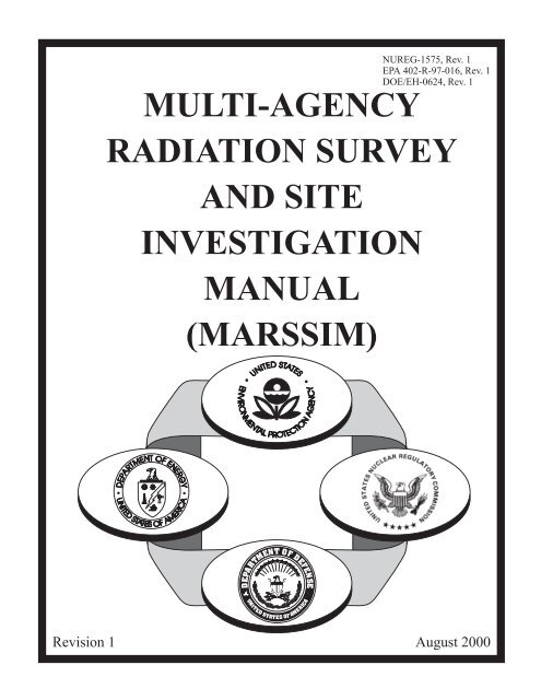
MULTI-AGENCY RADIATION SURVEY AND SITE<br />
INVESTIGATION MANUAL (<strong>MARSSIM</strong>)<br />
NUREG-1575, Rev. 1<br />
EPA 402-R-97-016, Rev. 1<br />
DOE/EH-0624,<br />
Rev. 1
ABSTRACT<br />
<strong>The</strong> <strong>MARSSIM</strong> provides information on planning, conducting, evaluating, and documenting<br />
building surface and surface soil final status radiological surveys for demonstrating compliance<br />
with dose or risk-based regulations or standards. <strong>The</strong> <strong>MARSSIM</strong> is a multi-agency consensus<br />
document that was developed collaboratively by four Federal agencies having authority and<br />
control over radioactive materials: Department of Defense (DOD), Department of Energy (DOE),<br />
Environmental Protection Agency (EPA), and Nuclear Regulatory Commission (NRC). <strong>The</strong><br />
<strong>MARSSIM</strong>’s objective is to describe a consistent approach for planning, performing, and<br />
assessing building surface and surface soil final status surveys to meet established dose or riskbased<br />
release criteria, while at the same time encouraging an effective use of resources.<br />
August 2000 iii <strong>MARSSIM</strong>, Revision 1
DISCLAIMER<br />
This manual was prepared by four agencies of the United States Government. Neither the United<br />
States Government nor any agency or branch thereof, or any of their employees, makes any<br />
warranty, expressed or implied, or assumes any legal liability of responsibility for any third<br />
party’s use, or the results of such use, of any information, apparatus, product, or process<br />
disclosed in this manual, or represents that its use by such third party would not infringe on<br />
privately owned rights.<br />
References within this manual to any specific commercial product, process, or service by trade<br />
name, trademark, or manufacturer does not constitute an endorsement or recommendation by the<br />
United States Government.<br />
<strong>MARSSIM</strong>, Revision 1 iv August 2000
CONTENTS<br />
Page<br />
Abstract .................................................................... iii<br />
Disclaimer .................................................................. iv<br />
Acknowledgments ........................................................... xix<br />
Abbreviations .............................................................. xxiii<br />
Conversion Factors ........................................................ xxvii<br />
Errata and Addenda ........................................................ xxviii<br />
Roadmap ........................................................... Roadmap-1<br />
1. Introduction .......................................................... 1-1<br />
1.1 Purpose and Scope of <strong>MARSSIM</strong> ................................... 1-1<br />
1.2 Structure of the Manual ........................................... 1-4<br />
1.3 Use of the Manual ............................................... 1-6<br />
1.4 Missions of the Federal Agencies Producing <strong>MARSSIM</strong> ................. 1-7<br />
1.4.1 Environmental Protection Agency ............................. 1-7<br />
1.4.2 Nuclear Regulatory Commission .............................. 1-7<br />
1.4.3 Department of Energy ...................................... 1-7<br />
1.4.4 Department of Defense ..................................... 1-8<br />
2. Overview of the Radiation Survey and Site Investigation Process ................ 2-1<br />
2.1 Introduction .................................................... 2-1<br />
2.2 Understanding Key <strong>MARSSIM</strong> Terminology .......................... 2-2<br />
2.3 Making Decisions Based on Survey Results ........................... 2-6<br />
2.3.1 Planning Effective Surveys—Planning Phase .................... 2-8<br />
2.3.2 Estimating the Uncertainty in Survey Results—<br />
Implementation Phase ..................................... 2-11<br />
2.3.3 Interpreting Survey Results—<strong>Assessment</strong> Phase . ................ 2-11<br />
2.3.4 Uncertainty in Survey Results ............................... 2-12<br />
2.3.5 Reporting Survey Results ................................... 2-13<br />
2.4 Radiation Survey and Site Investigation Process ....................... 2-14<br />
2.4.1 Site Identification ......................................... 2-16<br />
2.4.2 Historical Site <strong>Assessment</strong> .................................. 2-22<br />
2.4.3 Scoping Survey .......................................... 2-22<br />
2.4.4 Characterization Survey .................................... 2-23<br />
2.4.5 Remedial Action Support Survey ............................ 2-23<br />
2.4.6 Final Status Survey ....................................... 2-24<br />
2.4.7 Regulatory Agency Confirmation and Verification ............... 2-25<br />
2.5 Demonstrating Compliance With a Dose- or <strong>Risk</strong>-Based Regulation ....... 2-25<br />
2.5.1 <strong>The</strong> Decision To Use Statistical Tests ......................... 2-25<br />
2.5.2 Classification ............................................ 2-28<br />
2.5.3 Design Considerations for Small Areas of Elevated Activity ....... 2-29<br />
June 2001 v <strong>MARSSIM</strong>, Revision 1
CONTENTS<br />
Page<br />
2.5.4 Design Considerations for Relatively Uniform<br />
Distributions of Contamination .............................. 2-30<br />
2.5.5 Developing an Integrated Survey Design ....................... 2-31<br />
2.6 Flexibility in Applying <strong>MARSSIM</strong> Guidance ......................... 2-33<br />
2.6.1 Alternate Statistical Methods ................................ 2-34<br />
2.6.2 Alternate Null Hypothesis .................................. 2-39<br />
2.6.3 Integrating <strong>MARSSIM</strong> with Other Survey Designs . .............. 2-39<br />
3. Historical Site <strong>Assessment</strong> ............................................... 3-1<br />
3.1 Introduction .................................................... 3-1<br />
3.2 Data Quality Objectives ........................................... 3-2<br />
3.3 Site Identification ................................................ 3-4<br />
3.4 Preliminary Historical Site <strong>Assessment</strong> Investigation .................... 3-4<br />
3.4.1 Existing Radiation Data ..................................... 3-7<br />
3.4.2 Contracts and Interviews .................................... 3-9<br />
3.5 Site Reconnaissance .............................................. 3-9<br />
3.6 Evaluation of Historical Site <strong>Assessment</strong> Data ........................ 3-10<br />
3.6.1 Identify Potential Contaminants .............................. 3-11<br />
3.6.2 Identify Potentially Contaminated Areas ....................... 3-12<br />
3.6.3 Identify Potentially Contaminated Media ...................... 3-13<br />
3.6.4 Develop a Conceptual Model of the Site ....................... 3-21<br />
3.6.5 Professional Judgment ..................................... 3-22<br />
3.7 Determining the Next Step in the Site Investigation Process ............. 3-24<br />
3.8 Historical Site <strong>Assessment</strong> Report .................................. 3-24<br />
3.9 Review of the Historical Site <strong>Assessment</strong> ............................ 3-25<br />
4. Preliminary Survey Considerations ........................................ 4-1<br />
4.1 Introduction .................................................... 4-1<br />
4.2 Decommissioning Criteria ......................................... 4-1<br />
4.3 Identify Contaminants and Establish Derived Concentration Guideline Levels 4-3<br />
4.3.1 Direct Application of DCGLs ................................ 4-4<br />
4.3.2 DCGLs and the Use of Surrogate Measurements ................. 4-4<br />
4.3.3 Use of DCGLs for Sites With Multiple Radionulcides ............. 4-8<br />
4.3.4 Integrated Surface and Soil Contamination DCGLs ............... 4-8<br />
4.4 Classify Areas by Contamination Potential ........................... 4-11<br />
4.5 Select Background Reference Areas ................................ 4-13<br />
4.6 Identify Survey Units ............................................ 4-14<br />
<strong>MARSSIM</strong>, Revision 1 vi August 2000
CONTENTS<br />
Page<br />
4.7 Select Instruments and Survey Techniques ........................... 4-16<br />
4.7.1 Selection of Instruments .................................... 4-16<br />
4.7.2 Selection of Survey Techniques .............................. 4-17<br />
4.7.3 Criteria for Selection of Sample Collection and<br />
Direct Measurement Methods ............................... 4-19<br />
4.8 Site Preparation ................................................ 4-22<br />
4.8.1 Consent for Survey ........................................ 4-22<br />
4.8.2 Property Boundaries ....................................... 4-22<br />
4.8.3 Physical Characteristics of Site .............................. 4-22<br />
4.8.4 Clearing To Provide Access ................................. 4-24<br />
4.8.5 Reference Coordinate <strong>System</strong> ............................... 4-27<br />
4.9 Quality Control ................................................ 4-32<br />
4.9.1 Precision and <strong>System</strong>atic Errors (Bias) ........................ 4-33<br />
4.9.2 Number of Quality Control Measurements ..................... 4-34<br />
4.9.3 Controlling Sources of Error ................................ 4-38<br />
4.10 Health and Safety ............................................... 4-38<br />
5. Survey Planning and Design ............................................. 5-1<br />
5.1 Introduction .................................................... 5-1<br />
5.2 Scoping Surveys ................................................. 5-1<br />
5.2.1 General .................................................. 5-1<br />
5.2.2 Survey Design ............................................ 5-2<br />
5.2.3 Conducting Surveys ........................................ 5-3<br />
5.2.4 Evaluating Survey Results ................................... 5-3<br />
5.2.5 Documentation ............................................ 5-4<br />
5.3 Characterization Surveys .......................................... 5-7<br />
5.3.1 General .................................................. 5-7<br />
5.3.2 Survey Design ............................................ 5-8<br />
5.3.3 Conducting Surveys ........................................ 5-9<br />
5.3.4 Evaluating Survey Results .................................. 5-14<br />
5.3.5 Documentation ........................................... 5-15<br />
5.4 Remedial Action Support Surveys .................................. 5-18<br />
5.4.1 General ................................................. 5-18<br />
5.4.2 Survey Design ........................................... 5-18<br />
5.4.3 Conducting Surveys ....................................... 5-19<br />
5.4.4 Evaluating Survey Results .................................. 5-19<br />
5.4.5 Documentation ........................................... 5-19<br />
August 2000 vii <strong>MARSSIM</strong>, Revision 1
CONTENTS<br />
Page<br />
5.5 Final Status Surveys ............................................. 5-21<br />
5.5.1 General ................................................. 5-21<br />
5.5.2 Survey Design ........................................... 5-21<br />
5.5.3 Developing an Integrated Survey Strategy ...................... 5-46<br />
5.5.4 Evaluating Survey Results .................................. 5-52<br />
5.5.5 Documentation ........................................... 5-52<br />
6. Field Measurement Methods and Instrumentation ............................. 6-1<br />
6.1 Introduction .................................................... 6-1<br />
6.2 Data Quality Objectives ........................................... 6-2<br />
6.2.1 Identifying Data Needs ...................................... 6-2<br />
6.2.2 Data Quality Indicators ..................................... 6-3<br />
6.3 Selecting a Service Provider to Perform Field Data Collection Activities .... 6-8<br />
6.4 Measurement Methods ........................................... 6-10<br />
6.4.1 Direct Measurements ...................................... 6-10<br />
6.4.2 Scanning Surveys ......................................... 6-13<br />
6.5 Radiation Detection Instrumentation ................................ 6-15<br />
6.5.1 Radiation Detectors ....................................... 6-15<br />
6.5.2 Display and Recording Equipment ........................... 6-17<br />
6.5.3 Instrument Selection ...................................... 6-18<br />
6.5.4 Instrument Calibration ..................................... 6-20<br />
6.6 Data Conversion ................................................ 6-28<br />
6.6.1 Surface Activity .......................................... 6-29<br />
6.6.2 Soil Radionuclide Concentration and Exposure Rates ............ 6-31<br />
6.7 Detection Sensitivity ............................................ 6-31<br />
6.7.1 Direct Measurement Sensitivity .............................. 6-32<br />
6.7.2 Scanning Sensitivity ....................................... 6-37<br />
6.8 Measurement Uncertainty (Error) .................................. 6-49<br />
6.8.1 <strong>System</strong>atic and Random Uncertainties ........................ 6-50<br />
6.8.2 Statistical Counting Uncertainty ............................. 6-52<br />
6.8.3 Uncertainty Propagation .................................... 6-52<br />
6.8.4 Reporting Confidence Intervals .............................. 6-53<br />
6.9 Radon Measurements ............................................ 6-55<br />
6.9.1 Direct Radon Measurements ................................ 6-58<br />
6.9.2 Radon Progeny Measurements ............................... 6-59<br />
6.9.3 Radon Flux Measurements ................................. 6-60<br />
6.10 Special Equipment .............................................. 6-61<br />
6.10.1 Positioning <strong>System</strong>s ....................................... 6-61<br />
6.10.2 Mobile <strong>System</strong>s with Integrated Positioning <strong>System</strong>s ............. 6-62<br />
6.10.3 Radar, Magnetometer, and Electromagnetic Sensors ............. 6-63<br />
6.10.4 Aerial Radiological Surveys ................................ 6-66<br />
<strong>MARSSIM</strong>, Revision 1 viii August 2000
CONTENTS<br />
Page<br />
7. Sampling and Preparation for Laboratory Measurements ....................... 7-1<br />
7.1 Introduction .................................................... 7-1<br />
7.2 Data Quality Objectives ........................................... 7-1<br />
7.2.1 Identifying Data Needs ...................................... 7-2<br />
7.2.2 Data Quality Indicators ..................................... 7-2<br />
7.3 Communications with the Laboratory ................................ 7-7<br />
7.3.1 Communications During Survey Planning ...................... 7-8<br />
7.3.2 Communications Before and During Sample Collection . ........... 7-8<br />
7.3.3 Communications During Sample Analysis ...................... 7-9<br />
7.3.4 Communications Following Sample Analysis . ................... 7-9<br />
7.4 Selecting a Radioanalytical Laboratory .............................. 7-10<br />
7.5 Sampling ..................................................... 7-11<br />
7.5.1 Surface Soil ............................................. 7-12<br />
7.5.2 Building Surfaces ......................................... 7-15<br />
7.5.3 Other Media ............................................. 7-16<br />
7.6 Field Sample Preparation and Preservation ........................... 7-16<br />
7.6.1 Surface Soil ............................................. 7-17<br />
7.6.2 Building Surfaces ......................................... 7-17<br />
7.6.3 Other Media ............................................. 7-17<br />
7.7 Analytical Procedures ........................................... 7-17<br />
7.7.1 Photon Emitting Radionuclides .............................. 7-21<br />
7.7.2 Beta Emitting Radionuclides ................................ 7-21<br />
7.7.3 Alpha Emitting Radionuclides ............................... 7-22<br />
7.8 Sample Tracking ............................................... 7-23<br />
7.8.1 Field Tracking Considerations ............................... 7-24<br />
7.8.2 Transfer of Custody ....................................... 7-24<br />
7.8.3 Laboratory Tracking ....................................... 7-25<br />
7.9 Packaging and Transporting Samples ............................... 7-25<br />
7.9.1 U.S. Nuclear Regulatory Commission Regulations . .............. 7-27<br />
7.9.2 U.S. Department of Transportation Regulations ................. 7-27<br />
7.9.3 U.S. Postal Service Regulations .............................. 7-28<br />
8. Interpretation of Survey Results ........................................... 8-1<br />
8.1 Introduction .................................................... 8-1<br />
8.2 Data Quality <strong>Assessment</strong> .......................................... 8-1<br />
8.2.1 Review the Data Quality Objectives and Sampling<br />
Design .................................................. 8-2<br />
8.2.2 Conduct a Preliminary Data Review ........................... 8-2<br />
8.2.3 Select the Tests ........................................... 8-6<br />
August 2000 ix <strong>MARSSIM</strong>, Revision 1
CONTENTS<br />
Page<br />
8.2.4 Verify the Assumptions of the Tests ........................... 8-7<br />
8.2.5 Draw Conclusions From the Data ............................. 8-8<br />
8.2.6 Example ................................................ 8-10<br />
8.3 Contaminant Not Present in Background ............................. 8-11<br />
8.3.1 One-Sample Statistical Test ................................. 8-11<br />
8.3.2 Applying the Sign Test .................................... 8-12<br />
8.3.3 Sign Test Example: Class 2 Exterior Soil Survey Unit ............ 8-12<br />
8.3.4 Sign Test Example: Class 3 Exterior Soil Survey Unit ............ 8-14<br />
8.4 Contaminant Present in Background ................................ 8-17<br />
8.4.1 Two-Sample Statistical Test ................................ 8-17<br />
8.4.2 Applying the Wilcoxon Rank Sum Test ....................... 8-18<br />
8.4.3 Wilcoxon Rank Sum Test Example:<br />
Class 2 Interior Drywall Survey Unit .......................... 8-19<br />
8.4.4 Wilcoxon Rank Sum Test Example:<br />
Class 1 Interior Concrete Survey Unit ......................... 8-21<br />
8.4.5 Multiple Radionuclides .................................... 8-21<br />
8.5 Evaluating the Results: <strong>The</strong> Decision ............................... 8-21<br />
8.5.1 Elevated Measurement Comparison .......................... 8-21<br />
8.5.2 Interpretation of Statistical Test Results ....................... 8-23<br />
8.5.3 If the Survey Unit Fails .................................... 8-23<br />
8.5.4 Removable Activity ....................................... 8-25<br />
8.6 Documentation ................................................. 8-25<br />
9. Quality Assurance and Quality Control ..................................... 9-1<br />
9.1 Introduction .................................................... 9-1<br />
9.2 Development of a Quality Assurance Project Plan ...................... 9-3<br />
9.3 Data <strong>Assessment</strong> ................................................ 9-5<br />
9.3.1 Data Verification .......................................... 9-6<br />
9.3.2 Data Validation ........................................... 9-7<br />
References ............................................................... Ref-1<br />
Appendix A Example of <strong>MARSSIM</strong> Applied to a Final Status Survey ................ A-1<br />
A.1 Introduction ................................................... A-1<br />
A.2 Survey Preparations ..............................................A.1<br />
A.3 Survey Design ................................................. A-7<br />
A.4 Conducting Surveys ............................................ A-14<br />
A.5 Evaluating Survey Results ....................................... A-15<br />
<strong>MARSSIM</strong>, Revision 1 x August 2000
CONTENTS<br />
Page<br />
Appendix B Simplified Procedure for Certain Users of Sealed Sources, Short<br />
Half-Life Materials, and Small Quantities . ............................B-1<br />
Appendix C Site Regulations and Requirements Associated With Radiation<br />
Surveys and Site Investigations .....................................C-1<br />
C.1 EPA Statutory Authorities .........................................C-1<br />
C.2 DOE Regulations and Requirements .................................C-4<br />
C.3 NRC Regulations and Requirements ................................C-12<br />
C.4 DOD Regulations and Requirements ................................C-15<br />
C.5 State and Local Regulations and Requirements ........................C-20<br />
Appendix D <strong>The</strong> Planning Phase of the Data Life Cycle ........................... D-1<br />
D.1 State the Problem ............................................... D-4<br />
D.2 Identify the Decision ............................................ D-5<br />
D.3 Identify the Inputs to the Decision .................................. D-5<br />
D.4 Define the Boundaries of the Study ................................. D-6<br />
D.5 Develop a Decision Rule ......................................... D-8<br />
D.6 Specify Limits on Decision Errors ................................. D-13<br />
D.7 Optimize the Design for Collecting Data ............................ D-28<br />
Appendix E <strong>The</strong> <strong>Assessment</strong> Phase of the Data Life Cycle ..........................E-1<br />
E.1 Review DQOs and Survey Design ...................................E-1<br />
E.2 Conduct a Preliminary Data Review .................................E-3<br />
E.3 Select the Statistical Test ..........................................E-4<br />
E.4 Verify the Assumptions of the Statistical Test ..........................E-4<br />
E.5 Draw Conclusions from the Data ....................................E-5<br />
Appendix F <strong>The</strong> Relationship Between the Radiation Survey and Site<br />
Investigation Process, the CERCLA Remedial or Removal Process,<br />
and the RCRA Correction Action Process . ............................ F-1<br />
Appendix G Historical Site <strong>Assessment</strong> <strong>Information</strong> Sources ....................... G-1<br />
Appendix H Description of Field Survey and Laboratory Analysis Equipment ......... H-1<br />
H.1 Introduction ................................................... H-3<br />
H.2 Field Survey Equipment .......................................... H-5<br />
H.3 Laboratory Instruments ......................................... H-38<br />
June 2001 xi <strong>MARSSIM</strong>, Revision 1
CONTENTS<br />
Page<br />
Appendix I Statistical Tables and Procedures .................................... I-1<br />
I.1 Normal Distribution .............................................. I-1<br />
I.2 Sample Sizes for Statistical Tests ................................... I-2<br />
I.3 Critical Values for the Sign Test .................................... I-4<br />
I.4 Critical Values for the WRS Test ................................... I-6<br />
I.5 Probability of Detecting an Elevated Area ............................ I-11<br />
I.6 Random Numbers .............................................. I-14<br />
I.7 Stem and Leaf Display ........................................... I-17<br />
I.8 Quantile Plots .................................................. I-18<br />
I.9 Power Calculations for the Statistical Tests ........................... I-25<br />
I.10 Spreadsheet Formulas for the Wilcoxon Rank Sum Test ................ I-30<br />
I.11 Example WRS Test for Two Radionuclides .......................... I-31<br />
Appendix J Derivation of Alpha Scanning Equations Presented in Section 6.7.2.2 . ...... J-1<br />
Appendix K Comparison Tables Between Quality Assurance Documents ............. K-1<br />
Appendix L Regional Radiation Program Managers ...............................L-1<br />
L.1 Department of Energy ............................................L-2<br />
L.2 Environmental Protection Agency ...................................L-3<br />
L.3 Nuclear Regulatory Commission ....................................L-5<br />
L.4 Department of the Army ..........................................L-6<br />
L.5 Department of the Navy ...........................................L-7<br />
L.6 Department of the Air Force .......................................L-8<br />
Appendix M Sampling Methods: A List of Sources .............................. M-1<br />
M.1 Introduction ................................................... M-1<br />
M.2 List of Sources ................................................. M-1<br />
Appendix N Data Validation Using Data Descriptors ............................. N-1<br />
N.1 Reports to Decision Maker ....................................... N-1<br />
N.2 Documentation ................................................. N-2<br />
N.3 Data Sources .................................................. N-4<br />
N.4 Analytical Method and Detection Limit ............................. N-4<br />
N.5 Data Review ................................................... N-5<br />
N.6 Data Quality Indicators .......................................... N-6<br />
Glossary ................................................................. GL-1<br />
Index ................................................................. Index-1<br />
<strong>MARSSIM</strong>, Revision 1 xii June 2001
CONTENTS<br />
LIST OF TABLES<br />
Page<br />
1.1 Scope of <strong>MARSSIM</strong> ................................................... 1-8<br />
2.1 <strong>The</strong> Data Life Cycle used to Support the Radiation Survey and<br />
Site Investigation Process .............................................. 2-16<br />
2.2 Recommended Conditions for Demonstrating Compliance Based on Survey Unit<br />
Classification for a Final Status Survey .................................... 2-32<br />
2.3 Examples of Alternate Statistical Tests .................................... 2-35<br />
3.1 Questions Useful for the Preliminary HSA Investigation ....................... 3-5<br />
4.1 Selection of Direct Measurement Techniques Based on Experience .............. 4-20<br />
4.2 Example of DQO Planning Considerations ................................. 4-21<br />
4.3 Upper Confidence Limits for the True Variance as a Function of the Number of<br />
QC Measurements used to Determine the Estimated Variance .................. 4-36<br />
5.1 Values of P r for Given Values of the Relative Shift, )/F, when the<br />
Contaminant is Present in Background .................................... 5-28<br />
5.2 Percentiles Represented by Selected Values of " and $ ....................... 5-28<br />
5.3 Values of N/2 for Use with the Wilcoxon Rank Sum Test ..................... 5-30<br />
5.4 Values of Sign p for Given Values of the Relative Shift, )/F, when the<br />
Contaminant is Not Present in Background ................................. 5-32<br />
5.5 Values of N for Use with the Sign Test .................................... 5-34<br />
5.6 Illustrative Examples of Outdoor Area Dose Factors ......................... 5-37<br />
5.7 Illustrative Examples of Indoor Area Dose Factors ........................... 5-37<br />
5.8 Example Final Status Survey Investigation Levels ........................... 5-45<br />
5.9 Recommended Survey Coverage for Structures and Land Areas ................ 5-47<br />
6.1 Radiation Detectors With Applications for Alpha Surveys ..................... 6-20<br />
6.2 Radiation Detectors With Applications for Beta Surveys ...................... 6-21<br />
6.3 Radiation Detectors With Applications for Gamma Surveys ................... 6-22<br />
6.4 Examples of Estimated Detection Sensitivities for Alpha and Beta Survey<br />
Instrumentation ...................................................... 6-36<br />
6.5 Values of dN for Selected True Positive and False Positive Proportions ........... 6-40<br />
6.6 Scanning Sensitivity (MDCR) of the Ideal Observer for Various<br />
Background Levels .................................................... 6-41<br />
August 2000 xiii <strong>MARSSIM</strong>, Revision 1
LIST OF TABLES<br />
Page<br />
6.7 NaI(Tl) Scintillation Detector Scan MDCs for Common Radiological<br />
Contaminants ........................................................ 6-47<br />
6.8 Probability of Detecting 300 dpm/100 cm2 of Alpha Activity While Scanning with<br />
Alpha Detectors Using an Audible Output ................................. 6-49<br />
6.9 Areas Under Various Intervals About the Mean of a Normal Distribution ......... 6-54<br />
6.10 Radiation Detectors with Applications to Radon Surveys . ..................... 6-57<br />
6.11 Typical Radar Penetration Depths for Various Geologic Materials .............. 6-64<br />
7.1 Soil Sampling Equipment .............................................. 7-14<br />
7.2 Examples of Sources for Routine Analytical Methods ........................ 7-18<br />
7.3 Typical Measurement Sensitivities for Laboratory Radiometric Procedures ....... 7-20<br />
8.1 Methods for Checking the Assumptions of Statistical Tests ..................... 8-8<br />
8.2 Summary of Statistical Tests ............................................. 8-9<br />
8.3 Final Status Survey Parameters for Example Survey Units ..................... 8-10<br />
8.4 Example Sign Analysis: Class 2 Exterior Soil Survey Unit .................... 8-14<br />
8.5 Sign Test Example Data for Class 3 Exterior Survey Unit ..................... 8-16<br />
8.6 WRS Test for Class 2 Interior Drywall Survey Unit .......................... 8-20<br />
9.1 <strong>The</strong> Elements of a Quality <strong>System</strong> Related to the Data Life Cycle ................ 9-2<br />
9.2 Examples of QAPP Elements for Site Surveys and Investigations ................ 9-4<br />
9.3 Suggested Content or Consideration, Impact if Not Met, and Corrective Actions<br />
for Data Descriptors .................................................... 9-8<br />
A.1 Class 1 Interior Concrete Survey Unit and Reference Area Data ............... A-15<br />
A.2 Stem and Leaf Displays for Class 1 Interior Concrete Survey Unit .............. A-16<br />
A.3 WRS Test for Class 1 Interior Concrete Survey Unit ........................ A-18<br />
C.1 DOE Authorities, Orders and Regulations Related to Radiation Protection .........C-5<br />
C.2 Agreement States .....................................................C-21<br />
C.3 States that Regulate Diffuse NORM ......................................C-21<br />
D.1 Example Representation of Decision Errors for a Final Status Survey ........... D-15<br />
F.1 Program Comparison ...................................................F-5<br />
F.2 Data Elements for Site Visits ............................................F-10<br />
F.3 Comparison of Sampling Emphasis Between Remedial Site <strong>Assessment</strong><br />
and Removal <strong>Assessment</strong> ..............................................F-10<br />
G.1 Site <strong>Assessment</strong> <strong>Information</strong> Sources (Organized by <strong>Information</strong> Needed) ........ G-2<br />
G.2 Site <strong>Assessment</strong> <strong>Information</strong> Sources (Organized by <strong>Information</strong> Source) ......... G-7<br />
<strong>MARSSIM</strong>, Revision 1 xiv August 2000
LIST OF TABLES<br />
Page<br />
H.1 Radiation Detectors with Applications to Alpha Surveys ..................... H-50<br />
H.2 Radiation Detectors with Applications to Beta Surveys ...................... H-52<br />
H.3 Radiation Detectors with Applications to Gamma Surveys .................... H-53<br />
H.4 Radiation Detectors with Applications to Radon Surveys . .................... H-55<br />
H.5 <strong>System</strong>s that Measure Atomic Mass or Emissions .......................... H-56<br />
I.1 Cumulative Normal Distribution Function M(z) .............................. I-1<br />
I.2a Sample Sizes for Sign Test .............................................. I-2<br />
I.2b Sample Sizes for Wilcoxon Rank Sum Test ................................. I-3<br />
I.3 Critical Values for the Sign Test Statistic S+ ................................ I-4<br />
I.4 Critical Values for the WRS Test ......................................... I-6<br />
I.5 <strong>Risk</strong> that an Elevated Area with Length L/G and Shape S will not be Detected<br />
and the Area (%) of the Elevated Area Relative to a<br />
Triangular Sample Grid Area of 0.866 G 2 .................................. I-11<br />
I.6 1,000 Random Numbers Uniformly Distributed between Zero and One .......... I-14<br />
I.7 Data for Quantile Plot ................................................. I-19<br />
I.8 Ranked Reference Area Concentrations ................................... I-22<br />
I.9 Interpolated Ranks for Survey Unit Concentrations I-23<br />
I.10 Values of P r and p 2 for Computing the Mean and Variance of W MW .............. I-28<br />
I.11 Spreadsheet Formulas Used in Table 8.6 ................................... I-30<br />
I.12 Example WRS Test for Two Radionuclides ................................ I-35<br />
K.1 Comparison of EPA QA/R-5 and EPA QAMS-005/80 ........................ K-2<br />
K.2 Comparison of EPA QA/R-5 and ASME NQA-1 ............................ K-3<br />
K.3 Comparison of EPA QA/R-5 and DOE Order 5700.6c ........................ K-4<br />
K.4 Comparison of EPA QA/R-5 and MIL-Q-9858A ............................ K-5<br />
K.5 Comparison of EPA QA/R-5 and ISO 9000 ................................ K-6<br />
N.1 Use of Quality Control Data ............................................ N-7<br />
N.2 Minimum Considerations for Precision, Impact if Not Met,<br />
and Corrective Actions ................................................ N-9<br />
N.3 Minimum Considerations for Bias, Impact if Not Met,<br />
and Corrective Actions ............................................... N-10<br />
N.4 Minimum Considerations for Representativeness, Impact if Not Met,<br />
and Corrective Actions ............................................... N-13<br />
N.5 Minimum Considerations for Comparability, Impact if Not Met,<br />
and Corrective Actions ............................................... N-15<br />
N.6 Minimum Considerations for Completeness, Impact if Not Met,<br />
and Corrective Actions ............................................... N-16<br />
June 2001 xv <strong>MARSSIM</strong>, Revision 1
CONTENTS<br />
LIST OF FIGURES<br />
Page<br />
1.1 Compliance Demonstration .............................................. 1-2<br />
2.1 <strong>The</strong> Data Life Cycle .................................................... 2-7<br />
2.2 <strong>The</strong> Data Quality Objectives Process ...................................... 2-10<br />
2.3 <strong>The</strong> <strong>Assessment</strong> Phase of the Data Life Cycle ............................... 2-12<br />
2.4 <strong>The</strong> Radiation Survey and Site Investigation Process<br />
in Terms of Area Classification .......................................... 2-17<br />
2.5 <strong>The</strong> Historical Site <strong>Assessment</strong> Portion of the<br />
Radiation Survey and Site Investigation Process ............................. 2-18<br />
2.6 <strong>The</strong> Scoping Survey Portion of the Radiation Survey and<br />
Site Investigation Process .............................................. 2-19<br />
2.7 <strong>The</strong> Characterization and Remedial Action Support Survey Portion of the<br />
Radiation Survey and Site Investigation Process ............................. 2-20<br />
2.8 <strong>The</strong> Final Status Survey Portion of the Radiation Survey and<br />
Site Investigation Process .............................................. 2-21<br />
3.1 Example Showing How a Site Might Be Classified Prior to Cleanup<br />
Based on the Historical Site <strong>Assessment</strong> ................................... 3-23<br />
3.2 Example of a Historical Site <strong>Assessment</strong> Report Format ...................... 3-26<br />
4.1 Sequence of Preliminary Activities Leading to Survey Design ................... 4-2<br />
4.2 Flow Diagram for Selection of Field Survey Instrumentation for<br />
Direct Measurements and Analysis of Samples .............................. 4-18<br />
4.3 Indoor Grid Layout With Alphanumeric Grid Block Designation ................ 4-28<br />
4.4 Example of a Grid <strong>System</strong> for Survey of Site Grounds Using Compass Directions . . 4-29<br />
4.5 Example of a Grid <strong>System</strong> for Survey of Site Grounds Using Distances<br />
Left or Right of the Baseline ............................................ 4-30<br />
5.1 Flow Diagram Illustrating the Process for Identifying Measurement Locations ..... 5-22<br />
5.2 Flow Diagram for Identifying the Number of Data Points, N, for Statistical Tests . . . 5-23<br />
5.3 Flow Diagram for Identifying Data Needs for <strong>Assessment</strong> of Potential Areas of<br />
Elevated Activity in Class 1 Survey Units .................................. 5-24<br />
5.4 Example of a Random Measurement Pattern ................................ 5-41<br />
5.5 Example of a Random-Start Triangular Grid Measurement Pattern .............. 5-43<br />
6.1 <strong>The</strong> Physical Probe Area of a Detector .................................... 6-29<br />
6.2 Graphically Represented Probabilities for Type I and Type II Errors in Detection<br />
Sensitivity for Instrumentation With a Background Response .................. 6-33<br />
<strong>MARSSIM</strong>, Revision 1 xvi August 2000
LIST OF FIGURES<br />
Page<br />
8.1 Examples of Posting Plots ............................................... 8-4<br />
8.2 Example of a Frequency Plot ............................................. 8-5<br />
9.1 Example of a QAPP Format ............................................. 9-5<br />
A.1 Plot Plan for the Specialty Source Manufacturing Company ................... A-3<br />
A.2 Building Floor Plan ................................................... A-4<br />
A.3 Examples of Scanning Patterns for Each Survey Unit Classification ............. A-6<br />
A.4 Reference Coordinate <strong>System</strong> for the Class 1 Interior Concrete Survey Unit ....... A-8<br />
A.5 Power Chart for the Class 1 Interior Concrete Survey Unit ..................... A-9<br />
A.6 Prospective Power Curve for the Class 1 Interior Concrete Survey Unit ......... A-12<br />
A.7 Measurement Grid for the Class 1 Interior Concrete Survey Unit ............... A-13<br />
A.8 Quantile-Quantile Plot for the Class 1 Interior Concrete Survey Unit ........... A-17<br />
A.9 Retrospective Power Curve for the Class 1 Interior Concrete Survey Unit ........ A-20<br />
D.1 <strong>The</strong> Data Quality Objectives Process ...................................... D-2<br />
D.2 Repeated Applications of the DQO Process Throughout the<br />
Radiation Survey and Site Investigation Process ............................. D-3<br />
D.3 Example of the Parameter of Interest for the 1-Sample Case .................. D-11<br />
D.4 Example of the Parameter of Interest for the 2-Sample Case .................. D-12<br />
D.5 Possible Statement of the Null Hypothesis for the Final Status Survey<br />
Addressing the Issue of Compliance ..................................... D-18<br />
D.6 Possible Statement of the Null Hypothesis for the Final Status Survey<br />
Addressing the Issue of Indistinguishability from Background . ................ D-19<br />
D.7 Geometric Probability of Sampling at Least One Point of an<br />
Area of Elevated Activity as a Function of Sample Density with<br />
Either a Square or Triangular Sampling Pattern ............................ D-24<br />
D.8 Example of a Power Chart Illustrating the Decision Rule for the<br />
Final Status Survey .................................................. D-25<br />
D.9 Example of an Error Chart Illustrating the Decision Rule for the<br />
Final Status Survey .................................................. D-27<br />
E.1 <strong>The</strong> <strong>Assessment</strong> Phase of the Data Life Cycle ................................E-2<br />
F.1 Comparison of the Radiation Survey and Site Investigation Process with the<br />
CERCLA Superfund Process and the RCRA Corrective Action Process ........... F-2<br />
August 2000 xvii <strong>MARSSIM</strong>, Revision 1
LIST OF FIGURES<br />
Page<br />
I.1 Example of a Stem and Leaf Display ...................................... I-18<br />
I.2 Example of a Quantile Plot ............................................. I-20<br />
I.3 Quantile Plot for Example Class 2 Exterior Survey Unit of Section 8.3.3 ......... I-21<br />
I.4 Example Quantile-Quantile Plot ......................................... I-24<br />
I.5 Retrospective Power Curve for Class 3 Exterior Survey Unit ................... I-26<br />
I.6 Retrospective Power Curve for Class 2 Interior Drywall Survey Unit ............ I-29<br />
J.1 Probability (P) of Getting One or More Counts When Passing Over a 100 cm 2<br />
Area Contaminated at 500 dpm/100 cm 2 Alpha .............................. J-5<br />
J.2 Probability (P) of Getting One or More Counts When Passing Over a 100 cm 2<br />
Area Contaminated at 1,000 dpm/100 cm 2 Alpha ............................. J-6<br />
J.3 Probability (P) of Getting One or More Counts When Passing Over a 100 cm 2<br />
Area Contaminated at 5,000 dpm/100 cm 2 Alpha ............................. J-7<br />
J.4 Probability (P) of Getting Two or More Counts When Passing Over a 100 cm 2<br />
Area Contaminated at 500 dpm/100 cm 2 Alpha .............................. J-8<br />
J.5 Probability (P) of Getting Two or More Counts When Passing Over a 100 cm 2<br />
Area Contaminated at 1,000 dpm/100 cm 2 Alpha ............................. J-9<br />
J.6 Probability (P) of Getting Two or More Counts When Passing Over a 100 cm 2<br />
Area Contaminated at 5,000 dpm/100 cm 2 Alpha ............................ J-10<br />
N.1 Measurement Bias and Random Measurement Uncertainty ................... N-11<br />
<strong>MARSSIM</strong>, Revision 1 xviii August 2000
ACKNOWLEDGMENTS<br />
<strong>The</strong> Multi-Agency Radiation Survey and Site Investigation Manual (<strong>MARSSIM</strong>) came about as a<br />
result of individuals—at the management level—within the Environmental Protection Agency<br />
(EPA), Nuclear Regulatory Commission (NRC), Department of Energy (DOE), and Department<br />
of Defense (DOD) who recognized the necessity for a standardized guidance document for<br />
investigating radioactively contaminated sites. <strong>The</strong> creation of the <strong>MARSSIM</strong> was facilitated by<br />
the cooperation of subject matter specialists from these agencies with management’s support and<br />
a willingness to work smoothly together toward reaching the common goal of creating a<br />
workable and user-friendly guidance manual. Special appreciation is extended to Robert A.<br />
Meck of the NRC and Anthony Wolbarst of EPA for developing the concept of a multi-agency<br />
work group and bringing together representatives from the participating agencies.<br />
<strong>The</strong> <strong>MARSSIM</strong> could not have been possible without the technical work group members who<br />
contributed their time, talent, and efforts to develop this consensus guidance document:<br />
CDR Colleen F. Petullo, U.S. Public Health Service, EPA, Chair<br />
EPA: Mark Doehnert<br />
Anthony Wolbarst, Ph.D.<br />
H. Benjamin Hull<br />
Sam Keith, CHP*<br />
Jon Richards<br />
NRC: Robert A. Meck, Ph.D.<br />
Anthony Huffert<br />
George E. Powers, Ph.D.<br />
David Fauver, CHP<br />
Cheryl Trottier<br />
DOE: Hal Peterson, CHP<br />
Kenneth Duvall<br />
Andrew Wallo III<br />
DOD: David Alberth, CHP (Army)<br />
LCDR Lino Fragoso, Ph.D. (Navy)<br />
Lt. Col. Donald Jordan (Air Force)<br />
Capt. Kevin Martilla (Air Force)<br />
Capt. Julie Coleman (Air Force)<br />
Special mention is extended to the Federal agency contractors for their assistance in developing<br />
the <strong>MARSSIM</strong>:<br />
EPA: Scott Hay (S. Cohen & Associates, Inc.)<br />
Todd Peterson, Ph.D. (S. Cohen & Associates, Inc.)<br />
Harry Chmelynski, Ph.D. (S. Cohen & Associates, Inc.)<br />
Ralph Kenning, CHP (S. Cohen & Associates, Inc.)<br />
NRC: Eric Abelquist, CHP (<strong>Oak</strong> <strong>Ridge</strong> Institute of Science and Education)<br />
James Berger (Auxier & Associates)<br />
Carl Gogolak, Ph.D. (DOE/EML, under contract with NRC)<br />
* Formerly with EPA National Air and Radiation Environmental Laboratory (NAREL). Currently with the Agency<br />
for Toxic Substances and Disease Registry (ATSDR).<br />
August 2000 xix <strong>MARSSIM</strong>, Revision 1
ACKNOWLEDGMENTS<br />
DOE: Robert Coleman, CHP (<strong>Oak</strong> <strong>Ridge</strong> National Laboratory)<br />
John Kirk Williams (<strong>Oak</strong> <strong>Ridge</strong> National Laboratory)<br />
Romance Carrier (<strong>Oak</strong> <strong>Ridge</strong> National Laboratory)<br />
A special thank you is extended to Emilio Braganza (EPA), Gregory Budd (EPA), Mary Clark,<br />
Ph.D. (EPA), Brian Littleton (EPA), John Karhnak (EPA), Sarah Seeley (EPA), Rett Sutton<br />
(EPA/SEE), Juanita Beeson (NRC), Stephen A. McGuire, Ph.D. (NRC), Walter Oliu (NRC), LT<br />
James Coleman (Navy), CDR David E. Farrand (U.S Navy), CAPT David George (Navy), CDR<br />
Garry Higgins (Navy), CAPT James Malinoski (Navy), Harlan Keaton (State of Florida), J.<br />
Michael Beck, J.D. (EMS), Tom McLaughlin, Ph.D. (SC&A), Kevin Miller, Ph.D. (DOE/EML),<br />
and the members of the EPA’s Science Advisory Board (SAB) for their assistance in developing<br />
the manual.<br />
<strong>The</strong> membership of the SAB Radiation Advisory Committee’s Review Subcommittee that<br />
conducted an extensive peer review of the <strong>MARSSIM</strong> includes:<br />
Chair<br />
James E. Watson, Jr., Ph.D., University of North Carolina at Chapel Hill<br />
Members<br />
William Bair, Ph.D., (Retired), Battelle Pacific Northwest Laboratory<br />
Stephen L. Brown, Ph.D., R2C2 (<strong>Risk</strong>s of Radiation and Chemical Compounds)<br />
June Fabryka-Martin, Ph.D., Los Alamos National Laboratory<br />
Thomas F. Gesell, Ph.D., Idaho State University<br />
F. Owen Hoffman, Ph.D., SENES <strong>Oak</strong> <strong>Ridge</strong>, Inc.<br />
Janet Johnson, Ph.D., Shepherd Miller, Inc.<br />
Bernd Kahn, Ph.D., Georgia Institute of Technology<br />
Ellen Mangione, M.D., Colorado Department of Health<br />
Paul J. Merges, Ph.D., New York State Department of Environmental Conservation<br />
SAB Consultants<br />
Michael E. Ginevan, Ph.D., M.E. Ginevan & Associates<br />
David G. Hoel, Ph.D., University of South Carolina<br />
David E. McCurdy, Ph.D., Yankee Atomic Electric Company<br />
Frank L. Parker, Ph.D., Vanderbilt University [Liaison from Environmental<br />
Management Advisory Board, U.S. Department of Energy]<br />
Science Advisory Board Staff<br />
K. Jack Kooyoomjian, Ph.D., Designated Federal Official, EPA<br />
Mrs. Diana L. Pozun, Staff Secretary, EPA<br />
<strong>MARSSIM</strong>, Revision 1 xx August 2000
ACKNOWLEDGMENTS<br />
<strong>The</strong> work group meetings were open to the public, and the following people attended meetings as<br />
technical experts at the request of the work group or as observers:<br />
K. Allison A.T. Kearney<br />
L. Abramson NRC<br />
R. Abu-Eid NRC<br />
W. Beck <strong>Oak</strong> <strong>Ridge</strong> Institute of<br />
Science and Education<br />
A. Boerner <strong>Oak</strong> <strong>Ridge</strong> Institute of<br />
Science and Education<br />
Lt. E. Bonano Air Force<br />
M. Boyd EPA<br />
J. Buckley NRC<br />
B. Burns Army<br />
W. Cottrell <strong>Oak</strong> <strong>Ridge</strong><br />
National Laboratory<br />
D. Culberson Nuclear Fuel Services,<br />
Inc.<br />
M.C. Daily NRC<br />
M. Eagle EPA<br />
M. Frank Booz, Allen & Hamilton<br />
F. Galpin RAE Corp.<br />
R. Gilbert Pacific Northwest<br />
Laboratory<br />
J.E. Glenn NRC<br />
J. Hacala Booz, Allen & Hamilton<br />
L. Hendricks Nuclear Environmental<br />
Services<br />
K. Hogan EPA<br />
R. Hutchinson National Institute of<br />
Standards and<br />
Technology<br />
G. Jablonowski EPA<br />
N. Lailas EPA<br />
H. Larson NRC<br />
G. Lindsey International Atomic<br />
Energy Agency<br />
J. Lux Kerr-McGee Corporation<br />
M. Mahoney Army<br />
J. Malaro NRC<br />
H. Morton Morton Associates<br />
H. Mukhoty EPA<br />
A.J. Nardi Westinghouse<br />
D. Ottlieg Westinghouse Hanford<br />
Company<br />
V. Patania <strong>Oak</strong> <strong>Ridge</strong><br />
National Laboratory<br />
C.L. Pittiglio NRC<br />
C. Raddatz NRC<br />
L. Ralston SC&A, Inc.<br />
P. Reed NRC<br />
R. Rodriguez <strong>Oak</strong> <strong>Ridge</strong><br />
National Laboratory<br />
N. Rohnig<br />
R. Schroeder Army<br />
C. Simmons Kilpatrick & Cody<br />
E. Stamataky EPA<br />
R. Story Foster Wheeler<br />
E. Temple EPA<br />
D. Thomas Air Force<br />
S. Walker EPA<br />
P. White EPA<br />
R. Wilhelm EPA<br />
August 2000 xxi <strong>MARSSIM</strong>, Revision 1
<strong>MARSSIM</strong>, Revision 1 xxii August 2000
ABBREVIATIONS<br />
AEA Atomic Energy Act<br />
AEC Atomic Energy Commission<br />
AFI Air Force Instructions<br />
ALARA as low as reasonably achievable<br />
AMC Army Material Command<br />
ANSI American National Standards Institute<br />
AR Army Regulations<br />
ARA Army Radiation Authorization<br />
ASTM American Society of Testing and Materials<br />
ATSDR Agency for Toxic Substances and Disease Registry<br />
CAA Clean Air Act<br />
Capt. Captain (Air Force)<br />
CAPT Captain (Navy)<br />
CDR Commander<br />
CEDE committed effective dose equivalent<br />
CERCLA Comprehensive Environmental Response, Compensation, and Liability Act<br />
CERCLIS Comprehensive Environmental Response, Compensation, and Liability<br />
<strong>Information</strong> <strong>System</strong><br />
CFR Code of Federal Regulations<br />
CHP Certified Health Physicist<br />
CPM counts per minute<br />
DCF dose conversion factor<br />
DCGL derived concentration guideline level<br />
DCGLEMC DCGL for small areas of elevated activity, used with the EMC<br />
DCGLW DCGL for average concentrations over a wide area, used with statistical tests<br />
DEFT Decision Error Feasibility Trials<br />
DLC Data Life Cycle<br />
DOD Department of Defense<br />
DOE Department of Energy<br />
DOT Department of Transportation<br />
DQA Data Quality <strong>Assessment</strong><br />
DQO Data Quality Objectives<br />
EERF Eastern Environmental Radiation Facility<br />
Ehf human factors efficiency<br />
EMC elevated measurement comparison<br />
EML Environmental Measurements Laboratory<br />
EMMI Environmental Monitoring Methods Index<br />
EPA Environmental Protection Agency<br />
EPIC Environmental Photographic Interpretation Center<br />
ERAMS Environmental Radiation Ambient Monitoring <strong>System</strong><br />
June 2001 xxiii <strong>MARSSIM</strong>, Revision 1
ABBREVIATIONS<br />
FEMA Federal Emergency Management Agency<br />
FIRM Flood Insurance Rate Maps<br />
FRDS Federal Reporting Data <strong>System</strong><br />
FSP Field Sampling Plan<br />
FWPCA Federal Water Pollution Control Act<br />
FUSRAP Formerly Utilized Sites Remedial Action Program<br />
GEMS Geographical Exposure Modeling <strong>System</strong><br />
GM Geiger-Mueller<br />
GPS global positioning system<br />
GRIDS Geographic Resources <strong>Information</strong> Data <strong>System</strong><br />
GWSI Ground Water Site Inventory<br />
H0 Ha null hypothesis<br />
alternative hypothesis<br />
HSA Historical Site <strong>Assessment</strong><br />
HSWA Hazardous and Solid Waste Amendments<br />
ISI <strong>Information</strong> <strong>System</strong> Inventory<br />
LC LD LBGR<br />
critical level<br />
detection limit<br />
lower bound of the gray region<br />
LCDR Lieutenant Commander<br />
LLRWPA Low Level Radioactive Waste Policy Act as Amended<br />
LT Lieutenant<br />
MARLAP Multi-Agency Radiation Laboratory Analytical Protocols (Manual)<br />
<strong>MARSSIM</strong> Multi-Agency Radiation Survey and Site Investigation Manual<br />
MCA multichannel analyzer<br />
MDC minimum detectable concentration<br />
MDCR minimum detectable count rate<br />
MED Manhattan Engineering District<br />
NARM naturally occurring or accelerator produced radioactive material<br />
NCAPS National Corrective Action Prioritization <strong>System</strong><br />
NCRP National Council on Radiation Protection and Measurements<br />
NCP National Contingency Plan<br />
NIST National Institute of Standards and Technology<br />
NORM naturally occurring radioactive material<br />
NPDC National Planning Data Corporation<br />
<strong>MARSSIM</strong>, Revision 1 xxiv August 2000
ABBREVIATIONS<br />
NPDES National Pollutant Discharge Elimination <strong>System</strong><br />
NRC Nuclear Regulatory Commission<br />
NWPA Nuclear Waste Policy Act<br />
NWWA National Water Well Association<br />
ODES Ocean Data Evaluation <strong>System</strong><br />
ORNL <strong>Oak</strong> <strong>Ridge</strong> National Laboratory<br />
ORISE <strong>Oak</strong> <strong>Ridge</strong> Institute for Science and Education<br />
PERALS photon electron rejecting alpha liquid scintillator<br />
PIC pressurized ionization chamber<br />
QA quality assurance<br />
QAPP Quality Assurance Project Plan<br />
QC quality control<br />
QMP Quality Management Plan<br />
RASP Radiological Affairs Support Program<br />
RAGS/HHEM <strong>Risk</strong> <strong>Assessment</strong> Guidance for Superfund/Human Health Evaluation Manual<br />
RC release criterion<br />
RCRA Resource Conservation and Recovery Act<br />
RCRIS Resource Conservation and Recovery <strong>Information</strong> <strong>System</strong><br />
RI/FS Remedial Investigation/Feasibility Study<br />
ROD Record of Decision<br />
RODS Records of Decision <strong>System</strong><br />
RSSI Radiation Survey and Site Investigation<br />
SARA Superfund Amendments and Reauthorization Act<br />
SAP Sampling and Analysis Plan<br />
SDWA Safe Drinking Water Act<br />
SFMP Surplus Facilities Management Program<br />
SOP Standard Operating Procedures<br />
STORET Storage and Retrieval of U.S. Waterways Parametric Data<br />
TEDE total effective dose equivalent<br />
TLD thermoluminescence dosimeter<br />
TRU transuranic<br />
TSCA Toxic Substances Control Act<br />
August 2000 xxv <strong>MARSSIM</strong>, Revision 1
ABBREVIATIONS<br />
UMTRCA Uranium Mill Tailings Radiation Control Act<br />
USGS United States Geological Survey<br />
USPHS United States Public Health Service<br />
USRADS Ultrasonic Ranging and Data <strong>System</strong><br />
WATSTORE National Water Data Storage and Retrieval <strong>System</strong><br />
WL working level<br />
WRS Wilcoxon rank sum<br />
WSR Wilcoxon signed ranks<br />
WT Wilcoxon test<br />
<strong>MARSSIM</strong>, Revision 1 xxvi August 2000
CONVERSION FACTORS<br />
To Convert From To Multiply By To Convert From To Multiply By<br />
acre hectare 0.405 meter (m) inch 39.4<br />
sq. meter (m2 ) 4,050<br />
mile 0.000621<br />
sq. feet (ft 2 ) 43,600 sq. meter (m 2 ) acre 0.000247<br />
becquerel (Bq) curie (Ci) 2.7x10 -11 hectare 0.0001<br />
dps 1 sq. feet (ft 2 ) 10.8<br />
pCi 27 sq. mile 3.86x10 -7<br />
Bq/kg pCi/g 0.027 m 3 liter 1,000<br />
Bq/m 2 dpm/100 cm 2 0.60 mrem mSv 0.01<br />
Bq/m 3 Bq/L 0.001 mrem/y mSv/y 0.01<br />
pCi/L 0.027 mSv mrem 100<br />
centimeter (cm) inch 0.394 mSv/y mrem/y 100<br />
Ci Bq 3.70x10 10 ounce (oz) liter (L) 0.0296<br />
pCi 1x10 12 pCi Bq 0.037<br />
dpm 2.22<br />
dps dpm 60 pCi/g Bq/kg 37<br />
pCi 27 pCi/L Bq/m 3 37<br />
dpm dps 0.0167 rad Gy 0.01<br />
pCi 0.451 rem mrem 1,000<br />
gray (Gy) rad 100 mSv 10<br />
hectare acre 2.47 Sv 0.01<br />
liter (L) cm 3 1000 seivert (Sv) mrem 100,000<br />
m 3 0.001 mSv 1,000<br />
ounce (fluid) 33.8 rem 100<br />
August 2000 xxvii <strong>MARSSIM</strong>, Revision 1
ERRATA AND ADDENDA<br />
In response to comments received on the December 1997 Multi-Agency Radiation Survey and<br />
Site Investigation Manual (<strong>MARSSIM</strong>), minor modifications were made to individual pages.<br />
Modifications to the manual that correct errors are listed as errata, while modifications made to<br />
clarify guidance or provide additional information are referred to as addenda. <strong>The</strong> pages affected<br />
by these modifications are listed here and have the date of the modification in the footer. A<br />
complete list of comments and resolutions is available on the <strong>MARSSIM</strong> web site at:<br />
http://www.epa.gov/radiation/marssim/<br />
August 2000<br />
Pages Modified to Correct Errata<br />
v, xv, xxvii, Roadmap-4, 1-3, 2-6, 2-11, 2-12, 4-33, 4-35, 4-36, 4-37, 4-38, 5-33, 6-4, 6-10, 6-23,<br />
6-37, 7-20, 8-19, 9-3, 9-4, 9-7, Ref-3, Ref-4, A-2, A-5, A-7, A-11, A-14, A-19, E-2, H-7, H-8, H-<br />
10, H-12, H-14, H-16, H-32, I-30, N-2, N-6, N-8, N-11, N-13<br />
Pages Modified to Provide Addenda<br />
xiii, xxiii, xxviii, 5-30, 5-34, 7-8, C-20, C-21, D-23, I-5, L-2, L-3, L-4, L-5, L-8, , M-10<br />
June 2001<br />
Pages Modified to Correct Errata<br />
v, xxiii, xxviii, Roadmap-8, 4-24, 5-12, 6-16 6-30, 6-37, 8-19, C-19<br />
Pages Modified to Provide Addenda<br />
8-23<br />
August 2002<br />
Pages Modified to Correct Errata<br />
Ref-3, Ref-4, Ref-8, L-1, L-2, L-3, L-4, L-5, L-6, L-7<br />
Pages Modified to Provide Addenda<br />
2-4, 3-12, 4-11, GL-11<br />
<strong>MARSSIM</strong>, Revision 1 xxviii August 2002
Introduction to <strong>MARSSIM</strong><br />
ROADMAP<br />
<strong>The</strong> Multi-Agency Radiation Survey and Site Investigation Manual (<strong>MARSSIM</strong>) provides<br />
detailed guidance for planning, implementing, and evaluating environmental and facility<br />
radiological surveys conducted to demonstrate compliance with a dose- or risk-based regulation.<br />
<strong>The</strong> <strong>MARSSIM</strong> guidance focuses on the demonstration of compliance during the final status<br />
survey following scoping, characterization, and any necessary remedial actions.<br />
<strong>The</strong> process of planning the survey, implementing the survey plan, and assessing the survey<br />
results prior to making a decision is called the Data Life Cycle. <strong>MARSSIM</strong> Chapter 2 and<br />
Appendix D provide detailed guidance on developing appropriate survey designs using the Data<br />
Quality Objectives (DQO) Process to ensure that the survey results are of sufficient quality and<br />
quantity to support the final decision. <strong>The</strong> survey design process is described in <strong>MARSSIM</strong><br />
Chapters 3, 4, and 5. Guidance on selecting appropriate measurement methods (i.e., scan<br />
surveys, direct measurements, samples) and measurement systems (i.e., detectors, instruments,<br />
analytical methods) is provided in <strong>MARSSIM</strong> Chapters 6 and 7 and Appendix H. Data Quality<br />
<strong>Assessment</strong> (DQA) is the process of assessing the survey results, determining that the quality of<br />
the data satisfies the objectives of the survey, and interpreting the survey results as they apply to<br />
the decision being made. <strong>The</strong> DQA process is described in <strong>MARSSIM</strong> Chapter 2 and<br />
Appendix E and is applied in <strong>MARSSIM</strong> Chapter 8. Quality Assurance and Quality Control<br />
(QA/QC) procedures are developed and recorded in survey planning documents, such as a<br />
Quality Assurance Project Plan (QAPP) which is described in <strong>MARSSIM</strong> Chapter 9.<br />
<strong>MARSSIM</strong> does not provide guidance for translating the release criterion into derived<br />
concentration guideline levels (DCGLs). <strong>MARSSIM</strong> discusses contamination of surface soil and<br />
building surfaces in detail. If other media (e.g., ground water, surface water, subsurface soil,<br />
equipment, vicinity properties) are potentially contaminated at the time of the final status survey,<br />
modifications to the <strong>MARSSIM</strong> survey design guidance and examples may be required.<br />
<strong>The</strong> Goal of the Roadmap<br />
<strong>The</strong> goal of the roadmap is to present a summary of the major steps in the design,<br />
implementation, and assessment of a final status survey and to identify where guidance on these<br />
steps is located in <strong>MARSSIM</strong>. A brief description of each step is included in the roadmap along<br />
with references to the sections of <strong>MARSSIM</strong> that provide more detailed guidance.<br />
This roadmap provides the user with basic guidance from <strong>MARSSIM</strong> combined with “rules of<br />
thumb” (indicated by L) for performing compliance demonstration surveys. <strong>The</strong> roadmap is not<br />
designed to be a stand-alone document, but to be used as a quick reference to <strong>MARSSIM</strong> for<br />
August 2000 Roadmap-1 <strong>MARSSIM</strong>, Revision 1
<strong>MARSSIM</strong> Roadmap<br />
users already familiar with the process of planning and performing surveys. Roadmap users will<br />
also find flow charts summarizing the major steps in the Radiation Survey and Site Investigation<br />
Process, combined with references to sections in <strong>MARSSIM</strong> where detailed guidance may be<br />
found. In addition, the roadmap serves as an overview and example for applying <strong>MARSSIM</strong><br />
guidance at sites with radioactive contamination of surface soil and building surfaces. <strong>The</strong><br />
roadmap assumes a working knowledge of <strong>MARSSIM</strong> terminology. If such knowledge is<br />
lacking, the user may refer to Section 2.2 of <strong>MARSSIM</strong> for definitions of key terms. In addition,<br />
a complete set of definitions is provided in the Glossary.<br />
Data Life Cycle<br />
Compliance demonstration is simply a decision as to whether or not a survey unit meets the<br />
release criterion. For most sites, this decision is supported by statistical tests based on the results<br />
of one or more surveys. <strong>The</strong> initial assumption used in <strong>MARSSIM</strong> is that each survey unit is<br />
contaminated above the release criterion until proven otherwise. <strong>The</strong> surveys are designed to<br />
provide the information needed to reject this initial assumption. <strong>MARSSIM</strong> recommends using<br />
the Data Life Cycle as a framework for planning, implementing, and evaluating survey results<br />
prior to making a decision. Figure 1 summarizes the major activities associated with each phase<br />
of the Data Life Cycle.<br />
Planning Stage<br />
<strong>The</strong> survey design is developed and documented using the Data Quality Objectives (DQO)<br />
Process (Section 2.3.1, Appendix D). <strong>The</strong> DQOs for the project are established and preliminary<br />
surveys (e.g., scoping, characterization) are performed to provide information necessary to design<br />
the final status survey for compliance demonstration. <strong>The</strong> DQOs for the project are re-evaluated<br />
for each of the preliminary surveys. <strong>The</strong> preliminary surveys may provide information for<br />
purposes other than compliance demonstration that are not discussed in <strong>MARSSIM</strong>. For<br />
example, a characterization survey may provide information to support evaluation of remedial<br />
alternatives. In addition, any of the preliminary surveys may be designed to demonstrate<br />
compliance with the release criterion as one of the survey objectives. <strong>The</strong>se alternate survey<br />
designs are developed based on site-specific considerations (Section 2.6). <strong>The</strong> planning phase of<br />
the Data Life Cycle produces a final status survey design that is used for demonstrating<br />
compliance with the release criterion. This design is recorded in planning documents, such as a<br />
Quality Assurance Project Plan (QAPP) described in Section 9.2.<br />
<strong>MARSSIM</strong>, Revision 1 Roadmap-2 August 2000
PLAN<br />
IMPLEMENT<br />
ASSESS<br />
DECIDE<br />
Uniform<br />
Expected Values<br />
N, L, MDC<br />
(Number of Measurements,<br />
Location of Measurements<br />
Selection of Measurement Method)<br />
Direct Measurements<br />
or Samples<br />
Statistical<br />
Tests<br />
Area Classification<br />
Survey Unit Identification<br />
Reference Coordinate <strong>System</strong><br />
Contaminant<br />
Distribution<br />
Integrated<br />
Survey Design<br />
Final Status Survey Data Acquisition<br />
(Scan Surveys, Direct Measurements,<br />
Sample Collection and Analysis)<br />
Expected Values<br />
Coverage, Scan MDC<br />
(Percent of Survey Unit Scanned,<br />
Size of Areas of Elevated Contamination,<br />
Selection of Measurement Method)<br />
Data Verification and Data Validation<br />
Review DQOs and Integrated Survey Design<br />
Graphical Analysis of Data<br />
Actual Survey Results<br />
(N, L, MDC)<br />
Elevated<br />
Measurement<br />
Comparison<br />
Pass/Fail Pass/Fail<br />
Decide if Survey Unit Demonstrates Compliance with<br />
Regulation Based on Results of Final Status Survey<br />
Areas of<br />
Elevated Activity<br />
Scan Surveys<br />
Figure 1 <strong>The</strong> Data Life Cycle Applied to a Final Status Survey<br />
<strong>MARSSIM</strong> Roadmap<br />
Data Inputs<br />
HSA, Scoping,<br />
Characterization,<br />
Remedial Action<br />
Support Surveys<br />
DCGLW<br />
and<br />
DCGLEMC<br />
August 2000 Roadmap-3 <strong>MARSSIM</strong>, Revision 1
<strong>MARSSIM</strong> Roadmap<br />
A minimum amount of information is needed from the preliminary surveys to develop an<br />
effective final status survey design. This includes<br />
! Sufficient information to justify classification and specification of boundaries for survey<br />
units (the default is Class 1 which results in the highest level of survey effort)<br />
! An estimate of the variability of the contaminant concentration in the survey unit ( s) and<br />
the reference area ( r) if necessary<br />
After the preliminary surveys are completed, the final status survey design can be developed.<br />
Figure 2 presents the major steps in the development of a survey design that integrates scanning<br />
surveys with direct measurements and sampling. Most of the steps are easy to understand and<br />
references to appropriate sections of <strong>MARSSIM</strong> are included in the flowchart. Several of these<br />
steps are important enough to justify additional discussion in this guide. <strong>The</strong>se steps are<br />
! Classify Areas by Contamination Potential<br />
! Group/Separate Areas into Survey Units<br />
! Determine Number of Data Points<br />
! Select Instrumentation<br />
! Develop an Integrated Survey Design<br />
Classify Areas by Contamination Potential (Section 4.4)<br />
Classification is a critical step in survey design because it determines the level of survey effort<br />
based on the potential for contamination. Overestimating the potential for contamination results<br />
in an unnecessary increase in the level of survey effort. Underestimating the potential for<br />
contamination greatly increases the probability of failing to demonstrate compliance based on the<br />
survey results. <strong>The</strong>re are two key decisions made when classifying areas: 1) is the average<br />
activity in the area likely to exceed the DCGL W, and 2) is the contamination present in small<br />
areas of elevated activity or is the contamination distributed relatively homogeneously across the<br />
area. Each of these decisions is considered separately when designing the survey and then<br />
combined into an integrated survey design. Class 1 areas, prior to remediation, are impacted<br />
areas with concentrations of residual radioactivity that exceed the DCGL W. Class 2 areas are<br />
impacted areas where concentrations of residual activity that exceed the DCGL W are not<br />
expected. Class 3 areas are impacted areas that have a low probability of containing areas with<br />
residual radioactivity. <strong>The</strong> information obtained from the preliminary surveys is crucial for<br />
classifying areas (see Figure 2.4).<br />
L Area classification considers both the level of contamination relative to the DCGL W and<br />
the distribution of the contamination. <strong>The</strong> contamination may be uniformly distributed or<br />
present as small areas of elevated activity.<br />
<strong>MARSSIM</strong>, Revision 1 Roadmap-4 August 2000
IDENTIFY<br />
CONTAMINANTS<br />
ESTABLISH<br />
DCGLs<br />
CLASSIFY AREAS BY<br />
CONTAMINATION<br />
POTENTIAL<br />
GROUP/SEPARATE<br />
AREAS INTO SURVEY<br />
UNITS<br />
IS THE<br />
CONTAMINANT<br />
PRESENT IN<br />
BKGD?<br />
No<br />
PREPARE SITE FOR<br />
SURVEY ACCESS<br />
ESTABLISH SURVEY<br />
LOCATION REFERENCE<br />
SYSTEM<br />
DETERMINE NUMBER<br />
OF DATA POINTS<br />
SELECT<br />
INSTRUMENTATION<br />
DEVELOP AN INTEGRATED<br />
SURVEY DESIGN<br />
Section 3.6.1, Section 4.3<br />
Section 4.3<br />
Section 2.5.2, Section 4.4<br />
Section 4.6<br />
Yes<br />
Section 4.8<br />
Section 4.8.5<br />
Section 5.5.2<br />
SELECT BKGD<br />
REFERENCE AREAS<br />
Section 4.5<br />
Section 4.7, Section 6.5.3, Section 7.5, Section 7.7, Appendix H<br />
Section 2.5.5, Section 5.5.3<br />
Figure 2 Flow Diagram for Designing a Final Status Survey<br />
<strong>MARSSIM</strong> Roadmap<br />
August 2000 Roadmap-5 <strong>MARSSIM</strong>, Revision 1
<strong>MARSSIM</strong> Roadmap<br />
Group/Separate Areas into Survey Units (Section 4.6)<br />
Survey units are limited in size based on classification, exposure pathway modeling assumptions,<br />
and site-specific conditions. Table 1 provides suggested survey unit areas based on area<br />
classification. <strong>The</strong> rationale for selecting a larger survey unit area should be developed using the<br />
DQO Process and fully documented.<br />
L<br />
Class 1<br />
Class 2<br />
Class 3<br />
Structures<br />
Land Areas<br />
Structures<br />
Land Areas<br />
Structures<br />
Land Areas<br />
Table 1 Suggested Survey Unit Areas<br />
Classification Suggested Area<br />
up to 100 m 2<br />
up to 2,000 m 2<br />
100 to 1,000 m 2<br />
2,000 to 10,000 m 2<br />
no limit<br />
no limit<br />
Survey unit areas should be consistent with exposure pathway modeling assumptions<br />
used to develop DCGLs.<br />
Determine Number of Data Points (Section 5.5.2)<br />
<strong>The</strong> number of data points is determined based on the selection of a statistical test, which in turn<br />
is based on whether or not the contaminant is present in background. Figure 3 presents a flow<br />
chart for determining the number of data points.<br />
<strong>The</strong> first step in determining the number of data points is to specify the acceptable decision error<br />
rates, and . Decision error rates are site-specific and selected using the DQO Process.<br />
Changes in the values of and may result from successive iterations of the DQO Process.<br />
L Values for and are site-specific and selected using the DQO Process.<br />
<strong>MARSSIM</strong>, Revision 1 Roadmap-6 August 2000
ESTIMATE F, VARIABILITY IN THE<br />
CONTAMINANT LEVEL<br />
CALCULATE RELATIVE SHIFT<br />
)/F<br />
IS<br />
)/F<br />
BETWEEN<br />
1 AND 3?<br />
Section 5.5.2.3<br />
Section 5.5.2.3<br />
OBTAIN NUMBER OF DATA POINTS<br />
FOR SIGN TEST, N, FROM<br />
TABLE 5.5<br />
SPECIFY DECISION<br />
ERRORS<br />
Section 5.5.2.1<br />
No<br />
IS THE<br />
CONTAMINANT<br />
PRESENT IN<br />
BKGD?<br />
Yes<br />
Section 4.5<br />
No ADJUST LBGR ADJUST LBGR No<br />
<strong>MARSSIM</strong> Roadmap<br />
ESTIMATE F 's, VARIABILITIES<br />
IN BACKGROUND AND<br />
CONTAMINANT LEVELS<br />
Section<br />
5.5.2.2<br />
CALCULATE RELATIVE SHIFT<br />
)/F<br />
IS<br />
)/F<br />
BETWEEN<br />
1 AND 3?<br />
Yes Yes<br />
PREPARE SUMMARY OF DATA<br />
POINTS FROM SURVEY AREAS<br />
Section<br />
5.5.2.2<br />
OBTAIN NUMBER OF DATA POINTS<br />
FOR WRS TEST, N/2, FROM<br />
TABLE 5.3 FOR EACH SURVEY UNIT<br />
AND REFERENCE AREA<br />
PREPARE SUMMARY OF DATA<br />
POINTS FROM SURVEY AREAS<br />
Section 5.5.2.3 Section 5.5.2.2<br />
Figure 3 Flow Diagram for Determining the Number of Data Points<br />
August 2000 Roadmap-7 <strong>MARSSIM</strong>, Revision 1
<strong>MARSSIM</strong> Roadmap<br />
<strong>The</strong> next step, after determining whether or not the contaminant is present in background, is to<br />
estimate the variability of the contaminant concentration, . <strong>The</strong> standard deviation of the<br />
contaminant concentration determined from the preliminary survey results should provide an<br />
appropriate estimate of . If the contaminant is present in background, the variability in the<br />
survey unit ( s) and the variability in the reference area ( r) should both be estimated. <strong>The</strong> larger<br />
of the two values should be selected for determining the number of data points. Underestimating<br />
can underestimate the number of measurements needed to demonstrate compliance with the<br />
regulation, which increases the probability the survey unit will fail the statistical test.<br />
Overestimating can result in collecting more data than is necessary to demonstrate compliance.<br />
L It is better to overestimate values of s and r.<br />
L When s and r are different, select the larger of the two values.<br />
<strong>The</strong> third step is to calculate the relative shift, /. <strong>The</strong> variability of the contaminant<br />
concentration, , was determined in the previous step. <strong>The</strong> shift, , is equal to the width of the<br />
gray region. <strong>The</strong> upper bound of the gray region is defined as the DCGL W. <strong>The</strong> lower bound of<br />
the gray region (LBGR) is a site-specific parameter, adjusted to provide a value for / between<br />
one and three. / can be adjusted using the following steps:<br />
! Initially select LBGR to equal one half the DCGL W. This means = (DCGL W - LBGR)<br />
also equals one half the DCGL W. Calculate /.<br />
! If / is between one and three, obtain the appropriate number of data points from Table<br />
5.3 or Table 5.5.<br />
! If / is less than one, select a lower value for LBGR. Continue to select lower values<br />
for LBGR until / is greater than or equal to one, or until LBGR equals zero.<br />
! If / is greater than three, select a higher value for LBGR. Continue to select higher<br />
values for LBGR until / is less than or equal to three.<br />
Alternatively, / can be adjusted by solving the following equation and calculating /:<br />
LBGR ' DCGL W & <br />
If LBGR is less than zero, / can be calculated as DCGL W/.<br />
L Adjust the LBGR to provide a value for / between one and three.<br />
<strong>MARSSIM</strong>, Revision 1 Roadmap-8 June 2001
<strong>MARSSIM</strong> Roadmap<br />
<strong>The</strong> final step in determining the number of data points is to obtain the appropriate value from<br />
Table 5.3 or Table 5.5. Table 5.3 provides the number of data points for each survey unit and<br />
each reference area when the contaminant is present in background (N/2). Table 5.5 provides the<br />
number of data points for each survey unit when the contaminant is not present in background<br />
(N).<br />
Select Instrumentation (Section 4.7, Section 6.5.3, Section 7.5, Section 7.7, Appendix H)<br />
Instrumentation or measurement techniques should be selected based on detection sensitivity to<br />
provide technically defensible results that meet the objectives of the survey. Because of the<br />
uncertainty associated with interpreting scanning results, the detection sensitivity of the selected<br />
instruments should be as far below the DCGL as possible. For direct measurements and sample<br />
analyses, minimum detectable concentrations (MDCs) less than 10% of the DCGL are preferable<br />
while MDCs up to 50% of the DCGL are acceptable.<br />
L<br />
Estimates of the MDC that minimize potential decision errors should be used for planning<br />
surveys.<br />
Develop an Integrated Survey Design (Section 5.5.3)<br />
<strong>The</strong> integrated survey design combines scanning surveys with direct measurements and<br />
sampling. <strong>The</strong> level of survey effort is determined by the potential for contamination as<br />
indicated by the survey unit classification. This is illustrated in Figure 4. Class 3 survey units<br />
receive judgmental scanning and randomly located measurements. Class 2 survey units receive<br />
scanning over a portion of the survey unit based on the potential for contamination combined<br />
with direct measurements and sampling performed on a systematic grid. Class 1 survey units<br />
receive scanning over 100% of the survey unit combined with direct measurements and sampling<br />
performed on a systematic grid. <strong>The</strong> grid spacing is adjusted to account for the scan MDC<br />
(Section 5.5.2.4).<br />
Table 2 provides a summary of the recommended survey coverage for structures and land areas.<br />
Modifications to the example survey designs may be required to account for other contaminated<br />
media (e.g., ground water, subsurface soil).<br />
Implementation Phase<br />
<strong>The</strong> objectives outlined in the QAPP are incorporated into Standard Operating Procedures<br />
(SOPs). <strong>The</strong> final status survey design is carried out in accordance with the SOPs and the QAPP<br />
resulting in the generation of raw data. Chapter 6, Chapter 7, and Appendix H provide<br />
information on measurement techniques.<br />
August 2000 Roadmap-9 <strong>MARSSIM</strong>, Revision 1
<strong>MARSSIM</strong> Roadmap<br />
Class 1<br />
CONDUCT SURFACE<br />
SCANS FOR 100% OF LAND<br />
AREAS AND STRUCTURES<br />
Section 6.4.2<br />
DETERMINE NUMBER OF<br />
DATA POINTS NEEDED<br />
Section 5.5.2.2<br />
Section 5.5.2.3<br />
ADJUST GRID SPACING<br />
BASED ON SCAN MDC<br />
Section 5.5.2.4<br />
GENERATE A RANDOM<br />
STARTING POINT<br />
Section 5.5.2.5<br />
IDENTIFY DATA POINT GRID<br />
LOCATIONS<br />
Section 5.5.2.5<br />
WHERE CONDITIONS<br />
PREVENT SURVEY OF<br />
IDENTIFIED LOCATIONS,<br />
SUPPLEMENT WITH<br />
ADDITIONAL RANDOMLY<br />
SELECTED LOCATIONS<br />
PERFORM<br />
MEASUREMENTS AT DATA<br />
POINT GRID LOCATIONS<br />
WHAT IS THE<br />
AREA CLASSIFICATION?<br />
Class 2<br />
CONDUCT SURFACE<br />
SCANS FOR 10-100% OF<br />
LAND AREAS AND<br />
STRUCTURES<br />
Section 6.4.2<br />
DETERMINE NUMBER OF<br />
DATA POINTS NEEDED<br />
Section 5.5.2.2<br />
Section 5.5.2.3<br />
GENERATE A RANDOM<br />
STARTING POINT<br />
Section 5.5.2.5<br />
IDENTIFY DATA POINT GRID<br />
LOCATIONS<br />
Section 5.5.2.5<br />
WHERE CONDITIONS<br />
PREVENT SURVEY OF<br />
IDENTIFIED LOCATIONS,<br />
SUPPLEMENT WITH<br />
ADDITIONAL RANDOMLY<br />
SELECTED LOCATIONS<br />
PERFORM<br />
MEASUREMENTS AT DATA<br />
POINT GRID LOCATIONS<br />
Section 4.4<br />
Class 3<br />
CONDUCT JUDGMENTAL<br />
SURFACE SCANS FOR<br />
LAND AREAS AND<br />
STRUCTURES<br />
Section 6.4.2<br />
DETERMINE NUMBER OF<br />
DATA POINTS NEEDED<br />
Section 5.5.2.2<br />
Section 5.5.2.3<br />
GENERATE SETS OF<br />
RANDOM VALUES<br />
Section 5.5.2.5<br />
MULTIPLY SURVEY UNIT<br />
DIMENSIONS BY RANDOM<br />
NUMBERS TO DETERMINE<br />
COORDINATES<br />
Section 5.5.2.5<br />
CONTINUE UNTIL THE<br />
NECESSARY NUMBER OF<br />
DATA POINTS ARE<br />
IDENTIFIED<br />
PERFORM<br />
MEASUREMENTS AT DATA<br />
POINT GRID LOCATIONS<br />
Section 6.4.1 Section 6.4.1 Section 6.4.1<br />
Section 7.4 Section 7.4 Section 7.4<br />
Figure 4 Flow Diagram for Developing an Integrated Survey Design<br />
<strong>MARSSIM</strong>, Revision 1 Roadmap-10 August 2000
Area<br />
Classification<br />
Table 2 Recommended Survey Coverage for Structures and Land Areas<br />
Surface<br />
Scans<br />
Structures Land Areas<br />
Surface Activity<br />
Measurements<br />
Class 1 100% Number of data points<br />
from statistical tests<br />
(Sections 5.5.2.2 and<br />
5.5.2.3); additional<br />
direct measurements<br />
and samples may be<br />
necessary for small<br />
areas of elevated<br />
activity (Section<br />
5.5.2.4)<br />
Class 2 10 to 100%<br />
(10 to 50% for upper<br />
walls and ceilings)<br />
<strong>System</strong>atic and<br />
Judgmental<br />
Class 3 Judgmental<br />
<strong>Assessment</strong> Phase<br />
Number of data points<br />
from statistical tests<br />
(Sections 5.5.2.2 and<br />
5.5.2.3)<br />
Number of data points<br />
from statistical tests<br />
(Sections 5.5.2.2 and<br />
5.5.2.3)<br />
Surface<br />
Scans<br />
<strong>MARSSIM</strong> Roadmap<br />
Surface Soil<br />
Measurements<br />
100% Number of data points<br />
from statistical tests<br />
(Sections 5.5.2.2 and<br />
5.5.2.3); additional<br />
direct measurements<br />
and samples may be<br />
necessary for small<br />
areas of elevated<br />
activity (Section<br />
5.5.2.4)<br />
10 to 100%<br />
<strong>System</strong>atic<br />
and<br />
Judgmental<br />
Judgmental<br />
Number of data points<br />
from statistical tests<br />
(Sections 5.5.2.2 and<br />
5.5.2.3)<br />
Number of data points<br />
from statistical tests<br />
(Sections 5.5.2.2 and<br />
5.5.2.3)<br />
<strong>The</strong> assessment phase of the Data Life Cycle includes verification and validation of the survey<br />
results combined with an assessment of the quantity and quality of the data. As previously<br />
stated, both the average level of contamination in the survey unit and the distribution of the<br />
contamination within the survey unit are considered during area classification. For this reason,<br />
the assessment phase includes a graphical review of the data to provide a visual representation of<br />
the radionuclide distribution, an appropriate statistical test to demonstrate compliance for the<br />
average concentration of a uniformly distributed radionuclide, and the elevated measurement<br />
comparison (EMC) to demonstrate compliance for small areas of elevated activity.<br />
<strong>The</strong> survey data are verified to ensure that SOPs specified in the survey design were followed<br />
and that the measurement systems were performed in accordance with the criteria specified in the<br />
QAPP (Section 9.3.1). <strong>The</strong> data are validated to ensure that the results support the objectives of<br />
the survey, as documented in the QAPP, or permit a determination that these objectives should<br />
August 2000 Roadmap-11 <strong>MARSSIM</strong>, Revision 1
<strong>MARSSIM</strong> Roadmap<br />
be modified (Section 9.3.2). <strong>The</strong> Data Quality <strong>Assessment</strong> (DQA) process is then applied using<br />
the verified and validated data to determine if the quality of the data satisfies the data user’s<br />
needs. DQA is described in Appendix E and is applied in Chapter 8.<br />
<strong>The</strong> first step in DQA is to review the DQOs and survey design to ensure that they are still<br />
applicable. For example, if the data suggest that a survey unit is misclassified, the DQOs and<br />
survey design would be modified for the new classification.<br />
<strong>The</strong> next step is to conduct a preliminary data review to learn about the structure of the data and<br />
to identify patterns, relationships, or potential anomalies. This review should include calculating<br />
basic statistical quantities (i.e., mean, standard deviation, median) and graphically presenting the<br />
data using at least a histogram and a posting plot. <strong>The</strong> results of the preliminary data review are<br />
also used to verify the assumptions of the tests. Some of the assumptions and possible methods<br />
for assessing them are summarized in Table 3. <strong>Information</strong> on diagnostic tests is provided in<br />
Section 8.2 and Appendix I.<br />
Table 3 Methods for Checking the Assumptions of Statistical Tests<br />
Assumption Diagnostic<br />
Spatial Independence Posting Plot (Figure 8.1)<br />
Symmetry Histogram (Figure 8.2)<br />
Quantile Plot (Figure I.2)<br />
Data Variance Sample Standard Deviation (Section 8.2)<br />
Power is Adequate Retrospective Power Chart<br />
(Sign Test, Figure I.5)<br />
(WRS Test, Figure I.6)<br />
<strong>The</strong> final step in interpreting the data is to draw conclusions from the data. Table 4 summarizes<br />
the statistical tests recommended in <strong>MARSSIM</strong>. Section 8.3 provides guidance on performing<br />
the Sign test when the contaminant is not present in background. Section 8.4 provides guidance<br />
on performing the Wilcoxon Rank Sum (WRS) test when the contaminant is present in<br />
background.<br />
<strong>MARSSIM</strong>, Revision 1 Roadmap-12 August 2000
Table 4 Summary of Statistical Tests<br />
Radionuclide not in background and radionuclide-specific measurements made:<br />
All measurements less than DCGL W<br />
Average greater than DCGL W<br />
Survey Result Conclusion<br />
Any measurement greater than DCGL W and the average<br />
less than DCGL W<br />
Survey unit meets release criterion<br />
<strong>MARSSIM</strong> Roadmap<br />
Survey unit does not meet release criterion<br />
Conduct Sign test and elevated measurement<br />
comparison<br />
Radionuclide in background or radionuclide non-specific (gross) measurements made:<br />
Survey Result Conclusion<br />
Difference between maximum survey unit measurement<br />
and minimum reference area measurements is less than<br />
DCGL W<br />
Difference of survey unit average and reference area<br />
average is greater than DCGL W<br />
Difference between any survey unit measurement and any<br />
reference area measurement greater than DCGL W and the<br />
difference of survey unit average and reference area<br />
average is less than DCGL W<br />
Survey unit meets release criterion<br />
Survey unit does not meet release criterion<br />
Conduct WRS test and elevated measurement<br />
comparison<br />
Table 5 provides examples of final status survey investigation levels for each survey unit<br />
classification and type of measurement. For a Class 1 survey unit, measurements above the<br />
DCGL W are not necessarily unexpected. However, a measurement above the DCGL W at one of<br />
the discrete measurement locations might be considered unusual if it were much higher than all<br />
of the other discrete measurements. Thus, any discrete measurement that is above both the<br />
DCGL W and the statistical-based parameter for the measurements should be investigated further.<br />
Any measurement, either at a discrete location or from a scan, that is above the DCGL EMC should<br />
be flagged for further investigation.<br />
In Class 2 or Class 3 areas, neither measurements above the DCGL W nor areas of elevated<br />
activity are expected. Any measurement at a discrete location exceeding the DCGL W in these<br />
areas should be flagged for further investigation. Because the survey design for Class 2 and<br />
Class 3 survey units is not driven by the EMC, the scanning MDC might exceed the DCGL W. In<br />
this case, any indication of residual radioactivity during the scan would warrant further<br />
investigation.<br />
August 2000 Roadmap-13 <strong>MARSSIM</strong>, Revision 1
<strong>MARSSIM</strong> Roadmap<br />
Survey Unit<br />
Classification<br />
Table 5 Summary of Investigation Levels<br />
Flag Direct Measurement or Sample Result When: Flag Scanning Measurement<br />
Result When:<br />
Class 1 > DCGL EMC or<br />
> DCGL W and > a statistical-based parameter value<br />
> DCGL EMC<br />
Class 2 > DCGL W > DCGL W or > MDC<br />
Class 3 > fraction of DCGL W > DCGL W or > MDC<br />
Because there is a low expectation for residual radioactivity in a Class 3 area, it may be prudent<br />
to investigate any measurement exceeding even a fraction of the DCGL W. <strong>The</strong> level one chooses<br />
here depends on the site, the radionuclides of concern, and the measurement and scanning<br />
methods chosen. This level should be set using the DQO Process during the survey design phase<br />
of the Data Life Cycle. In some cases, the user may also decide to follow this procedure for<br />
Class 2 and even Class 1 survey units.<br />
Both the measurements at discrete locations and the scans are subject to the EMC. <strong>The</strong> result of<br />
the EMC does not in itself lead to a conclusion as to whether the survey unit meets or exceeds<br />
the release criterion, but is a flag or trigger for further investigation. <strong>The</strong> investigation may<br />
involve taking further measurements in order to determine that the area and level of the elevated<br />
residual radioactivity are such that the resulting dose or risk meets the release criterion. 1 <strong>The</strong><br />
investigation should also provide adequate assurance that there are no other undiscovered areas<br />
of elevated residual radioactivity in the survey unit that might result in a dose exceeding the<br />
release criterion. This could lead to a re-classification of all or part of a survey unit—that is,<br />
unless the results of the investigation indicate that reclassification is not necessary.<br />
Decision Making Phase<br />
A decision is made, in coordination with the responsible regulatory agency, based on the<br />
conclusions drawn from the assessment phase. <strong>The</strong> results of the EMC are used to demonstrate<br />
compliance with the dose- or risk-based regulation for small areas of elevated activity, while the<br />
nonparametric statistical tests are used to demonstrate that the average radionuclide concentration<br />
in the survey unit complies with the release criterion. <strong>The</strong> objective is to make technically<br />
defensible decisions with a specified level of confidence.<br />
1 Rather than, or in addition to, taking further measurements, the investigation may involve assessing the<br />
adequacy of the exposure pathway model used to obtain the DCGLs and area factors, and the consistency of the<br />
results obtained with the Historical Site <strong>Assessment</strong> and the scoping, characterization, and remedial action support<br />
surveys.<br />
<strong>MARSSIM</strong>, Revision 1 Roadmap-14 August 2000
<strong>MARSSIM</strong> Roadmap<br />
<strong>The</strong> EMC consists of comparing each measurement from the survey unit with the investigation<br />
levels in Table 5. <strong>The</strong> EMC is performed for measurements obtained from the systematic or<br />
random sample locations as well as locations flagged by scanning surveys. Any measurement<br />
from the survey unit that is equal to or greater than the investigation level indicates an area of<br />
relatively higher concentration and is investigated, regardless of the outcome of the<br />
nonparametric statistical tests.<br />
L<br />
Any measurement from the survey unit that is equal to or greater than the investigation<br />
level indicates an area of relatively higher concentration and is investigated, regardless of<br />
the outcome of the nonparametric statistical tests.<br />
<strong>The</strong> result of the Sign test or the WRS test is the decision to reject or not to reject the null<br />
hypothesis that the survey unit is contaminated above the DCGL W. Provided that the results of<br />
any investigations triggered by the EMC have been resolved, a rejection of the null hypothesis<br />
leads to the decision that the survey unit meets the release criterion. If necessary, the amount of<br />
residual radioactivity in the survey unit can be estimated so that dose or risk calculations can be<br />
made. In most cases, the average concentration is the best estimate for the amount of residual<br />
radioactivity.<br />
Summary<br />
<strong>The</strong> roadmap presents a summary of the planning, implementation, assessment, and decision<br />
making phases for a final status survey and identifies where guidance on these phases is located<br />
in <strong>MARSSIM</strong>. Each step in the process is described briefly along with references to the sections<br />
of <strong>MARSSIM</strong> to which the user may refer for more detailed guidance. Flow charts are provided<br />
to summarize the major steps in the Radiation Survey and Site Investigation Process, again citing<br />
appropriate sections of <strong>MARSSIM</strong>. In addition to providing the user with basic guidance from<br />
<strong>MARSSIM</strong>, the roadmap also includes “rules of thumb” for performing compliance<br />
demonstration surveys.<br />
August 2000 Roadmap-15 <strong>MARSSIM</strong>, Revision 1
1 INTRODUCTION<br />
1.1 Purpose and Scope of <strong>MARSSIM</strong><br />
Radioactive materials have been produced, processed, used, and stored at thousands of sites<br />
throughout the United States. Many of these sites—ranging in size from Federal weaponsproduction<br />
facilities covering hundreds of square kilometers to the nuclear medicine departments<br />
of small hospitals—were at one time or are now radioactively contaminated.<br />
<strong>The</strong> owners and managers of a number of sites would like to determine if these sites are<br />
contaminated, clean them up if contaminated, and release them for restricted use or for<br />
unrestricted public use. <strong>The</strong> Environmental Protection Agency (EPA), the Nuclear Regulatory<br />
Commission (NRC), and the Department of Energy (DOE) are responsible for the release of sites<br />
following cleanup. <strong>The</strong>se responsibilities apply to facilities under the control of Federal<br />
agencies, such as the DOE and Department of Defense (DOD), and to sites licensed by the NRC<br />
and its Agreement States. Some States have responsibilities for similar sites under their control.<br />
<strong>The</strong> Multi-Agency Radiation Survey and Site Investigation Manual (<strong>MARSSIM</strong>) provides a<br />
nationally consistent consensus approach to conducting radiation surveys and investigations at<br />
potentially contaminated sites. This approach should be both scientifically rigorous and flexible<br />
enough to be applied to a diversity of site cleanup conditions. <strong>MARSSIM</strong>’s title includes the<br />
term “survey” because it provides information on planning and conducting surveys, and includes<br />
the term “site investigation” because the process outlined in the manual allows one to begin by<br />
investigating any site (i.e., by gathering data or information) that may involve radioactive<br />
contamination.<br />
<strong>The</strong> decommissioning that follows remediation will normally require a demonstration to the<br />
responsible Federal or State agency that the cleanup effort was successful and that the release<br />
criterion (a specific regulatory limit) was met. In <strong>MARSSIM</strong>, this demonstration is given the<br />
name “final status survey.” This manual assists site personnel or others in performing or<br />
assessing such a demonstration. (Generally, <strong>MARSSIM</strong> may serve to guide or monitor<br />
remediation efforts whether or not a release criterion is applied.)<br />
As illustrated in Figure 1.1, the demonstration of compliance with respect to conducting surveys<br />
is comprised of three interrelated parts:<br />
I. Translate: Translating the cleanup/release criterion (e.g., mSv/y, mrem/y, specific risk)<br />
into a corresponding derived contaminant concentration level (e.g., Bq/kg or pCi/g in<br />
soil) through the use of environmental pathway modeling.<br />
August 2000 1-1 <strong>MARSSIM</strong>, Revision 1
Introduction<br />
Release<br />
Criterion<br />
Translate Measure Decide<br />
Modeling,<br />
Tables<br />
(DCGL)<br />
Survey<br />
&<br />
Sample<br />
<strong>MARSSIM</strong><br />
Figure 1.1 Compliance Demonstration<br />
Interpret<br />
Results,<br />
Statistical<br />
Tests<br />
II. Measure: Acquiring scientifically sound and defensible site-specific data on the levels<br />
and distribution of residual contamination, as well as levels and distribution of<br />
radionuclides present as background, by employing suitable field and/or laboratory<br />
measurement techniques. 1<br />
III. Decide: Determining that the data obtained from sampling does support the assertion that<br />
the site meets the release criterion, within an acceptable degree of uncertainty, through<br />
application of a statistically based decision rule.<br />
1 Measurements include field and laboratory analyses, however, <strong>MARSSIM</strong> leaves detailed discussions of<br />
laboratory sample analyses to another manual (i.e., a companion document, the Multi-Agency Radiation Laboratory<br />
Analytical Protocols (MARLAP) manual that is currently under development).<br />
<strong>MARSSIM</strong>, Revision 1 1-2 August 2000
Introduction<br />
<strong>MARSSIM</strong> presents comprehensive guidance—specifically for II and III above—for<br />
contaminated soil and buildings. This guidance describes a performance-based approach for<br />
demonstrating compliance with a dose- or risk-based regulation. This approach includes<br />
processes that identify data quality needs and may reveal limitations that enter into conducting a<br />
survey. <strong>The</strong> data quality needs stated as Data Quality Objectives (DQOs) include performance<br />
measures and goals in relation to a specific intended use of the data (EPA 1997a).<br />
DQOs must be developed on a site-specific basis. However, because of the large variability in<br />
the types of radiation sites, it is impossible to provide criteria that apply to every situation. As an<br />
example, <strong>MARSSIM</strong> presents a method for planning, implementing, assessing, and making<br />
decisions about regulatory compliance at sites with radioactive contaminants in surface soil and<br />
on building surfaces. In particular, <strong>MARSSIM</strong> describes generally acceptable approaches for:<br />
! planning and designing scoping, characterization, remediation-support, and final status<br />
surveys for sites with surface soil and building surface contamination<br />
! Historical Site <strong>Assessment</strong> (HSA)<br />
! QA/QC in data acquisition and analysis<br />
! conducting surveys<br />
! field and laboratory methods and instrumentation, and interfacing with radiation<br />
laboratories<br />
! statistical hypothesis testing, and the interpretation of statistical data<br />
! documentation<br />
Thus, <strong>MARSSIM</strong> provides standardized and consistent approaches for planning, conducting,<br />
evaluating, and documenting environmental radiological surveys, with a specific focus on the<br />
final status surveys that are carried out to demonstrate compliance with cleanup regulations.<br />
<strong>The</strong>se approaches may not meet the DQOs at every site, so other methods may be used to meet<br />
site-specific DQOs, as long as an equivalent level of performance can be demonstrated.<br />
Table 1.1, at the end of Chapter 1, summarizes the scope of <strong>MARSSIM</strong>. Several issues related to<br />
releasing sites are beyond the scope of <strong>MARSSIM</strong>. <strong>The</strong>se include translation of dose or risk<br />
standards into radionuclide specific concentrations, or demonstrating compliance with ground<br />
water or surface water regulations. <strong>MARSSIM</strong> can be applied to surveys performed at vicinity<br />
properties—those not under government or licensee control—but the decision to apply the<br />
<strong>MARSSIM</strong> at vicinity properties is outside the scope of <strong>MARSSIM</strong>. Other contaminated media<br />
(e.g., sub-surface soil, building materials, ground water) and the release of contaminated<br />
components and equipment are also not addressed by <strong>MARSSIM</strong>. With <strong>MARSSIM</strong>’s main<br />
focus on final status surveys, this manual continues a process of following remediation activities<br />
that are intended to remove below-surface contaminants. <strong>The</strong>refore, some of the reasons for<br />
limiting the scope of the guidance to contaminated surface soils and building surfaces include:<br />
1) contamination is limited to these media for many sites following remediation, 2) since many<br />
August 2000 1-3 <strong>MARSSIM</strong>, Revision 1
Introduction<br />
sites have surface soil and building surface contamination as the leading source of contamination,<br />
existing computer models used for calculating the concentrations based on dose or risk generally<br />
consider only surface soils or building surfaces as a source term, and 3) <strong>MARSSIM</strong> was written<br />
in support of cleanup rulemaking efforts for which supporting data are mostly limited to<br />
contaminated surface soil and building surfaces.<br />
<strong>MARSSIM</strong> also recognizes that there may be other factors, such as cost or stakeholder concerns,<br />
that have an impact on designing surveys. Guidance on how to address these specific concerns is<br />
outside the scope of <strong>MARSSIM</strong>. Unique site-specific cases may arise that require a modified<br />
approach beyond what is presently described in <strong>MARSSIM</strong>. This includes examples such as:<br />
1) the release of sites contaminated with naturally occurring radionuclides in which the<br />
concentrations corresponding to the release criteria are close to the variability of the background<br />
and 2) sites where a reference background cannot be established. However, the process of<br />
planning, implementing, assessing, and making decisions about a site described in <strong>MARSSIM</strong> is<br />
applicable to all sites, even if the examples in this manual do not meet a site’s specific objectives.<br />
Of <strong>MARSSIM</strong>’s many topics, the Data Quality Objective (DQO) approach to data acquisition<br />
and analysis and the Data Quality <strong>Assessment</strong> (DQA) for determining that data meet stated<br />
objectives are two elements that are a consistent theme throughout the manual. <strong>The</strong> DQO<br />
Process and DQA approach, described in Chapter 2, present a method for building common<br />
sense and the scientific method into all aspects of designing and conducting surveys, and making<br />
best use of the obtainable information. This becomes a formal framework for systematizing the<br />
planning of data acquisition surveys so that the data sought yield the kind of information actually<br />
needed for making important decisions—such as whether or not to release a particular site<br />
following remediation.<br />
1.2 Structure of the Manual<br />
<strong>MARSSIM</strong> begins with the overview of the Radiation Survey and Site Investigation Process in<br />
Chapter 2—Figures 2.4 through 2.8 are flowcharts that summarize the steps and decisions taken<br />
in the process. Chapter 3 provides instructions for performing an Historical Site <strong>Assessment</strong><br />
(HSA)—a detailed investigation to collect existing information on the site or facility and to<br />
develop a conceptual site model. <strong>The</strong> results of the HSA are used to plan surveys, perform<br />
measurements, and collect additional information at the site. Chapter 4 covers issues that arise in<br />
all types of surveys. Detailed information on performing specific types of surveys is included in<br />
Chapter 5. Guidance on selecting the appropriate instruments and measurement techniques for<br />
each type of measurement is in Chapters 6 and 7. Chapter 6 discusses direct measurements and<br />
scanning surveys, and Chapter 7 discusses sampling and sample preparation for laboratory<br />
measurements. <strong>The</strong> interpretation of survey results is described in Chapter 8. Chapter 9 provides<br />
guidance on data management, quality assurance (QA), and quality control (QC). <strong>Information</strong> on<br />
specific subjects related to radiation site investigation can be found in the appendices.<br />
<strong>MARSSIM</strong>, Revision 1 1-4 August 2000
Introduction<br />
<strong>MARSSIM</strong> contains several appendices to provide additional guidance on specific topics.<br />
Appendix A presents an example of how to apply the <strong>MARSSIM</strong> guidance to a specific site.<br />
Appendix B describes a simplified procedure for compliance demonstration that may be<br />
applicable at certain types of sites. Appendix C summarizes the regulations and requirements<br />
associated with radiation surveys and site investigations for each of the agencies involved in the<br />
development of <strong>MARSSIM</strong>. Detailed guidance on the DQO Process is in Appendix D, and<br />
Appendix E has guidance on DQA. Appendix F describes the relationships among <strong>MARSSIM</strong>,<br />
the Comprehensive Environmental Response, Compensation, and Liability Act (CERCLA), and<br />
the Resource Conservation and Recovery Act (RCRA). Sources of information used during site<br />
assessment are listed in Appendix G. Appendix H describes field survey and laboratory analysis<br />
equipment that may be used for radiation surveys and site investigations. Appendix I offers<br />
tables of statistical data and supporting information for interpreting survey results described in<br />
Chapter 8. <strong>The</strong> derivation of the alpha scanning detection limit calculations used in Chapter 6 is<br />
described in Appendix J. Comparison tables for QA documents are in Appendix K. Appendix L<br />
lists the regional radiation program managers for each of the agencies participating in the<br />
development of <strong>MARSSIM</strong>. Appendix M lists publications that serve as resources describing<br />
sampling methods. <strong>Information</strong> on data validation is provided in Appendix N.<br />
<strong>MARSSIM</strong> is presented in a modular format, with each module containing guidance on<br />
conducting specific aspects of, or activities related to, the survey process. Followed in order,<br />
each module leads to the generation and implementation of a complete survey plan. Although<br />
this approach may involve some overlap and redundancy in information, it also allows many<br />
users to concentrate only on those portions of the manual that apply to their own particular needs<br />
or responsibilities. <strong>The</strong> procedures within each module are listed in order of performance and<br />
options are provided to guide a user past portions of the manual that may not be specifically<br />
applicable to the user’s area of interest. Where appropriate, checklists condense and summarize<br />
major points in the process. <strong>The</strong> checklists may be used to verify that every suggested step is<br />
followed or to flag a condition in which specific documentation should explain why a step was<br />
not needed.<br />
Also included in the manual is a section titled Roadmap. <strong>The</strong> roadmap is designed to be used<br />
with <strong>MARSSIM</strong> as a quick reference for users already familiar with the process of planning and<br />
performing radiation surveys. <strong>The</strong> roadmap gives the user basic guidance, rules of thumb, and<br />
references to sections in the manual containing detailed guidance.<br />
<strong>MARSSIM</strong>, which is based on a graded approach, also contains a simplified procedure (see<br />
Appendix B) that many users of radioactive materials may—with the approval of the responsible<br />
regulatory agency—be able to employ to demonstrate compliance with the release criterion.<br />
Sites that may qualify for simplified release procedures are those in which the radioactive<br />
materials used were 1) of relatively short half-life (e.g., t 1/2 # 120 days) and have since decayed to<br />
insignificant quantities, 2) kept only in small enough quantities so as to be exempted or not<br />
August 2000 1-5 <strong>MARSSIM</strong>, Revision 1
Introduction<br />
requiring a specific license from a regulatory authority, 3) used or stored only in the form of nonleaking<br />
sealed sources, or 4) combinations of the above.<br />
1.3 Use of the Manual<br />
Potential users of this manual are Federal, State, and local government agencies having authority<br />
for control of radioactive environmental contamination; their contractors; and other parties, such<br />
as organizations with licensed authority to possess and use radioactive materials. <strong>The</strong> manual is<br />
intended for a technical audience having knowledge of radiation health physics and an<br />
understanding of statistics as well as experience with the practical applications of radiation<br />
protection. An understanding of instrumentation and methodologies and expertise in planning,<br />
approving, and implementing surveys of environmental levels of radioactive material is assumed.<br />
This manual has been written so that individuals responsible for planning, approving, and<br />
implementing radiological surveys will be able to understand and apply the guidance provided<br />
here. Certain situations and sites may require consultation with more experienced personnel.<br />
<strong>MARSSIM</strong> provides guidance for conducting radiation surveys and site investigations.<br />
<strong>MARSSIM</strong> uses the word “should” as a recommendation, that ought not be interpreted as a<br />
requirement. <strong>The</strong> reader need not expect that every recommendation in this manual will be taken<br />
literally and applied at every site. Rather, it is expected that the survey planning documentation<br />
will address how the guidance will be applied on a site-specific basis.<br />
As previously stated, <strong>MARSSIM</strong> supports implementation of dose- or risk-based regulations.<br />
<strong>The</strong> translation of the regulatory dose limit to a corresponding concentration level is not<br />
addressed in <strong>MARSSIM</strong>, so the guidance in this manual is applicable to a broad range of<br />
regulations, including risk- or concentration-based regulations. <strong>The</strong> terms dose and dose-based<br />
regulation are used throughout the manual, but these terms are not intended to limit the use of the<br />
manual.<br />
Note that Federal or State agencies that can approve a demonstration of compliance may support<br />
requirements that differ from what is presented in this version of <strong>MARSSIM</strong> . It is essential,<br />
therefore, that the persons carrying out the surveys, whether they are conducting surveys in<br />
accordance with the simplified approach of Appendix B or the full <strong>MARSSIM</strong> process, remain<br />
in close communication with the proper Federal or State authorities throughout the compliance<br />
demonstration process.<br />
<strong>MARSSIM</strong>, Revision 1 1-6 August 2000
1.4 Missions of the Federal Agencies Producing <strong>MARSSIM</strong><br />
Introduction<br />
<strong>MARSSIM</strong> is the product of a multi-agency workgroup with representatives from EPA, NRC,<br />
DOE, and DOD. This section briefly describes the missions of the participating agencies.<br />
Regulations and requirements governing site investigations for each of the agencies associated<br />
with radiation surveys and site investigations are presented in Appendix C.<br />
1.4.1 Environmental Protection Agency<br />
<strong>The</strong> mission of the U.S. Environmental Protection Agency (EPA) is to improve and preserve the<br />
quality of the environment, on both national and global levels. <strong>The</strong> EPA’s scope of<br />
responsibility includes implementing and enforcing environmental laws, setting guidelines,<br />
monitoring pollution, performing research, and promoting pollution prevention. EPA<br />
Headquarters maintains overall planning, coordination, and control of EPA programs, and EPA’s<br />
ten regional offices are responsible for executing EPA's programs within the boundaries of each<br />
region. EPA also coordinates with, and supports research and development of, pollution control<br />
activities carried out by State and local governments.<br />
1.4.2 Nuclear Regulatory Commission<br />
<strong>The</strong> mission of the U.S. Nuclear Regulatory Commission (NRC) is to ensure adequate protection<br />
of public health and safety, the common defense and security, and the environment in the use of<br />
certain radioactive materials in the United States. <strong>The</strong> NRC's scope of responsibility includes<br />
regulation of commercial nuclear power reactors; non-power research, test, and training reactors;<br />
fuel cycle facilities; medical, academic, and industrial uses of nuclear materials; and the<br />
transport, storage, and disposal of nuclear materials and waste. <strong>The</strong> Energy Reorganization Act<br />
of 1974 and the Atomic Energy Act of 1954, as amended, provide the foundation for regulation<br />
of the Nation's commercial use of radioactive materials.<br />
1.4.3 Department of Energy<br />
<strong>The</strong> mission of the Department of Energy (DOE) is to develop and implement a coordinated<br />
national energy policy to ensure the availability of adequate energy supplies and to develop new<br />
energy sources for domestic and commercial use. In addition, DOE is responsible for the<br />
development, construction and testing of nuclear weapons for the U.S. Military. DOE is also<br />
responsible for managing the low- and high-level radioactive wastes generated by past nuclear<br />
weapons and research programs and for constructing and maintaining a repository for civilian<br />
radioactive wastes generated by the commercial nuclear reactors. DOE has the lead in<br />
decontaminating facilities and sites previously used in atomic energy programs.<br />
August 2000 1-7 <strong>MARSSIM</strong>, Revision 1
Introduction<br />
1.4.4 Department of Defense<br />
<strong>The</strong> global mission of the Department of Defense (DOD) is to provide for the defense of the<br />
United States. In doing this, DOD is committed to protecting the environment. Each military<br />
service has specific regulations addressing the use of radioactive sources and the development of<br />
occupational health programs and radiation protection programs. <strong>The</strong> documents describing<br />
these regulations are used as guidance in developing environmental radiological surveys within<br />
DOD and are discussed in Appendix C.<br />
Table 1.1 Scope of <strong>MARSSIM</strong><br />
Within Scope of <strong>MARSSIM</strong> Beyond Scope of <strong>MARSSIM</strong><br />
Guidance <strong>MARSSIM</strong> provides technical<br />
guidance on conducting radiation<br />
surveys and site investigations.<br />
Tool Box <strong>MARSSIM</strong> can be thought of as an<br />
extensive tool box with many<br />
components—some within the text<br />
of <strong>MARSSIM</strong>, others by reference.<br />
Measurement <strong>The</strong> guidance given in <strong>MARSSIM</strong> is<br />
performance-based and directed<br />
towards acquiring site-specific data.<br />
Modeling <strong>The</strong> interface between environmental<br />
pathway modeling and <strong>MARSSIM</strong> is<br />
an important survey design<br />
consideration addressed in<br />
<strong>MARSSIM</strong>.<br />
Regulation <strong>MARSSIM</strong> does not set new<br />
regulations or non-technical issues<br />
(e.g., legal or policy) for site<br />
cleanup. Release criterion will be<br />
provided rather than calculated using<br />
<strong>MARSSIM</strong>.<br />
Tool Box Many topics are beyond the scope of<br />
<strong>MARSSIM</strong>, for example:<br />
-a public participation program<br />
-packaging and transportation of<br />
wastes for disposal<br />
-decontamination and stabilization<br />
techniques<br />
-training<br />
Procedure <strong>The</strong> approaches suggested in<br />
<strong>MARSSIM</strong> vary depending on the<br />
various site data needs—there are no<br />
set procedures for sample collection,<br />
measurement techniques, storage and<br />
disposal established in <strong>MARSSIM</strong>.<br />
Modeling Environmental pathway modeling<br />
and ecological endpoints in<br />
modeling are beyond the scope of<br />
<strong>MARSSIM</strong>.<br />
<strong>MARSSIM</strong>, Revision 1 1-8 August 2000
Table 1.1 Scope of <strong>MARSSIM</strong> (continued)<br />
Within Scope of <strong>MARSSIM</strong> Beyond Scope of <strong>MARSSIM</strong><br />
Soil and <strong>The</strong> two main media of interest in<br />
Buildings <strong>MARSSIM</strong> are contaminated surface<br />
soil and building surfaces.<br />
Final Status <strong>The</strong> focus of <strong>MARSSIM</strong> is on<br />
Survey the final status survey as this is the<br />
deciding factor in judging if the site<br />
meets the release criterion.<br />
Radiation <strong>MARSSIM</strong> only considers<br />
radiation-derived hazards.<br />
Remediation <strong>MARSSIM</strong> assists users in<br />
Method determining when sites are ready for<br />
a final status survey and provides<br />
guidance on how to determine if<br />
remediation was successful.<br />
DQO <strong>MARSSIM</strong> presents a systemized<br />
Process approach for designing surveys to<br />
collect data needed for making<br />
decisions such as whether or not to<br />
release a site.<br />
DQA <strong>MARSSIM</strong> provides a set of<br />
statistical tests for evaluating data<br />
and lists alternate tests that may be<br />
applicable at specific sites.<br />
Introduction<br />
Other Media <strong>MARSSIM</strong> does not cover other<br />
media, including construction<br />
materials, equipment, subsurface<br />
soil, surface or subsurface water,<br />
biota, air, sewers, sediments or<br />
volumetric contamination.<br />
Materials or <strong>MARSSIM</strong> does not recommend<br />
Equipment the use of any specific materials or<br />
equipment—there is too much<br />
variability in the types of radiation<br />
sites—this information will be in<br />
other documents.<br />
Chemicals <strong>MARSSIM</strong> does not deal with any<br />
hazards posed by chemical<br />
contamination.<br />
Remediation <strong>MARSSIM</strong> does not discuss<br />
Method selection and evaluation of remedial<br />
alternatives, public involvement,<br />
legal considerations, policy decisions<br />
related to planning<br />
DQO <strong>MARSSIM</strong> does not provide<br />
Process prescriptive or default values of<br />
DQOs.<br />
DQA <strong>MARSSIM</strong> does not prescribe a<br />
statistical test for use at all sites.<br />
August 2000 1-9 <strong>MARSSIM</strong>, Revision 1
2 OVERVIEW OF THE RADIATION SURVEY AND SITE<br />
INVESTIGATION PROCESS<br />
2.1 Introduction<br />
This chapter provides a brief overview of the Radiation Survey and Site Investigation (RSSI)<br />
Process, several important aspects of this Process, and its underlying principles. <strong>The</strong> concepts<br />
introduced here are discussed in detail throughout the manual.<br />
<strong>The</strong> purpose of <strong>MARSSIM</strong> is to provide a standardized approach to demonstrating compliance<br />
with a dose- or risk-based regulation. Since most of the manual is based on general technical and<br />
statistical concepts, much of the guidance can still be applied to other types of regulations or<br />
standards. <strong>The</strong> purpose of this chapter is to provide the overview information required to<br />
understand the rest of this manual.<br />
Section 2.2 introduces and defines key terms used throughout the manual. Some of these terms<br />
may be familiar to the <strong>MARSSIM</strong> user, while others are new terms developed specifically for<br />
this manual.<br />
Section 2.3 describes the flow of information used to decide whether or not a site or facility<br />
complies with a regulation. <strong>The</strong> section describes the framework that is used to demonstrate<br />
compliance with a regulation, and is the basis for all guidance presented in this manual. <strong>The</strong><br />
decision-making process is broken down into four phases: 1) planning, 2) implementation,<br />
3) assessment, and 4) decision making.<br />
Section 2.4 introduces the Radiation Survey and Site Investigation Process, which can be used<br />
for compliance demonstration at many sites. <strong>The</strong> section describes a series of surveys that<br />
combine to form the core of this process. Each survey has specified goals and objectives to<br />
support a final decision on whether or not a site or facility complies with the appropriate<br />
regulations. Flow diagrams showing how the different surveys support the overall process are<br />
provided, along with descriptions of the information provided by each type of survey.<br />
Section 2.5 presents major considerations that relate to the decision-making and survey-design<br />
processes. This section, as well as the examples discussed in detail throughout the manual,<br />
focuses on residual radioactive contamination in surface soils and on building surfaces.<br />
Recommended survey designs for demonstrating compliance are presented along with the<br />
rationale for selecting these designs.<br />
Section 2.6 recognizes that the methods presented in <strong>MARSSIM</strong> may not represent the optimal<br />
survey design at all sites. Some alternate methods for applying the Radiation Survey and Site<br />
Investigation process are discussed. Different methods for demonstrating compliance that are<br />
technically defensible may be developed with the approval of the responsible regulatory agency.<br />
August 2000 2-1 <strong>MARSSIM</strong>, Revision 1
Overview of the Radiation Survey and Site Investigation Process<br />
<strong>MARSSIM</strong> provides an approach that is technically defensible and flexible enough to be applied<br />
to a variety of site-specific conditions. Applying this guidance to a dose- or risk-based regulation<br />
provides a consistent approach to protecting human health and the environment. <strong>The</strong> manual’s<br />
performance-based approach to decision making provides the flexibility needed to address<br />
compliance demonstration at individual sites.<br />
2.2 Understanding Key <strong>MARSSIM</strong> Terminology<br />
<strong>The</strong> first step in understanding the Radiation Survey and Site Investigation (RSSI) Process is<br />
accomplished by understanding the scope of this manual, the terminology, and the concepts set<br />
forth. Some of the terms used in <strong>MARSSIM</strong> were developed for the purposes of this manual,<br />
while other commonly used terms are also adopted for use in <strong>MARSSIM</strong>. This section explains<br />
some of the terms roughly in the order of their presentation in the manual.<br />
<strong>The</strong> process described in <strong>MARSSIM</strong> begins with the premise that a release criterion has already<br />
been provided in terms of a measurement quantity. <strong>The</strong> methods presented in <strong>MARSSIM</strong> are<br />
generally applicable and are not dependent on the value of the release criterion.<br />
A release criterion is a regulatory limit expressed in terms of dose (mSv/y or mrem/y) or risk<br />
(cancer incidence or cancer mortality). <strong>The</strong> terms release limit or cleanup standard are also used<br />
to describe this term. A release criterion is typically based on the total effective dose equivalent<br />
(TEDE), the committed effective dose equivalent (CEDE), risk of cancer incidence (morbidity),<br />
or risk of cancer death (mortality) and generally cannot be measured directly. Exposure pathway<br />
modeling is used to calculate a radionuclide-specific predicted concentration or surface area<br />
concentration of specific nuclides that could result in a dose (TEDE or CEDE) or specific risk<br />
equal to the release criterion. In this manual, such a concentration is termed the derived<br />
concentration guideline level (DCGL). Exposure pathway modeling is an analysis of various<br />
exposure pathways and scenarios used to convert dose or risk into concentration. In many cases<br />
DCGLs can be obtained from responsible regulatory agency guidance based on default modeling<br />
input parameters, while other users may elect to take into account site-specific parameters to<br />
determine DCGLs. In general, the units for the DCGL are the same as the units for<br />
measurements performed to demonstrate compliance (e.g., Bq/kg or pCi/g, Bq/m 2 or dpm/100<br />
cm 2 ). This allows direct comparisons between the survey results and the DCGL. A discussion of<br />
the uncertainty associated with using DCGLs to demonstrate compliance is included in Appendix<br />
D, Section D.6.<br />
An investigation level is a radionuclide-specific level based on the release criterion that, if<br />
exceeded, triggers some response such as further investigation or remediation. An investigation<br />
level may be used early in decommissioning to identify areas requiring further investigation, and<br />
may also be used as a screening tool during compliance demonstration to identify potential<br />
problem areas. A DCGL is an example of a specific investigation level.<br />
<strong>MARSSIM</strong>, Revision 1 2-2 August 2000
Overview of the Radiation Survey and Site Investigation Process<br />
While the derivation of DCGLs is outside the scope of <strong>MARSSIM</strong>, it is important to understand<br />
the assumptions that underlie this derivation. <strong>The</strong> derivation assumptions must be consistent<br />
with those used for planning a compliance demonstration survey. One of the most important<br />
assumptions used for converting a dose or risk limit into a media-specific concentration is the<br />
modeled area of contamination. Other considerations include sample depth, composition,<br />
modeling parameters, and exposure scenarios. <strong>MARSSIM</strong> defines two potential DCGLs based<br />
on the area of contamination.<br />
! If the residual radioactivity is evenly distributed over a large area, <strong>MARSSIM</strong> looks at the<br />
1 average activity over the entire area. <strong>The</strong> DCGLW (the DCGL used for the statistical<br />
tests, see Section 2.5.1.2) is derived based on an average concentration over a large area.<br />
! If the residual radioactivity appears as small areas of elevated activity 2 within a larger<br />
area, typically smaller than the area between measurement locations, <strong>MARSSIM</strong><br />
considers the results of individual measurements. <strong>The</strong> DCGL EMC (the DCGL used for the<br />
elevated measurement comparison (EMC), see Section 2.5.3 and Section 2.5.4) is derived<br />
separately for these small areas and generally from different exposure assumptions than<br />
those used for larger areas.<br />
A site is any installation, facility, or discrete, physically separate parcel of land, or any building<br />
or structure or portion thereof, that is being considered for survey and investigation.<br />
Area is a very general term that refers to any portion of a site, up to and including the entire site.<br />
Decommissioning is the process of safely removing a site from service, reducing residual<br />
radioactivity through remediation to a level that permits release of the property, and termination<br />
of the license or other authorization for site operation. Although only part of the process, the<br />
term decommissioning is used in this sense for the Radiation Survey and Site Investigation<br />
(RSSI) Process, and is used this way throughout <strong>MARSSIM</strong>.<br />
1 <strong>The</strong> “W” in DCGLW stands for Wilcoxon Rank Sum test, which is the statistical test recommended in<br />
<strong>MARSSIM</strong> for demonstrating compliance when the contaminant is present in background. <strong>The</strong> Sign test<br />
recommended for demonstrating compliance when the contaminant is not present in background also uses the<br />
DCGL W.<br />
2 A small area of elevated activity, or maximum point estimate of contamination, might also be referred to as a<br />
“hot spot.” This term has been purposefully omitted from <strong>MARSSIM</strong> because the term often has different<br />
meanings based on operational or local program concerns. As a result, there may be problems associated with<br />
defining the term and reeducating <strong>MARSSIM</strong> users in the proper use of the term. Because these implications are<br />
inconsistent with <strong>MARSSIM</strong> concepts, the term is not used.<br />
August 2000 2-3 <strong>MARSSIM</strong>, Revision 1
Overview of the Radiation Survey and Site Investigation Process<br />
A survey unit is a physical area consisting of structure or land areas of specified size and shape<br />
for which a separate decision will be made as to whether or not that area exceeds the release<br />
criterion. This decision is made as a result of the final status survey—the survey in the RSSI<br />
Process used to demonstrate compliance with the regulation or standard. <strong>The</strong> size and shape of<br />
the survey unit are based on factors, such as the potential for contamination, the expected<br />
distribution of contamination, and any physical boundaries (e.g., buildings, fences, soil type,<br />
surface water body) at the site.<br />
For <strong>MARSSIM</strong>, measurement is used interchangeably to mean: 1) the act of using a detector to<br />
determine the level or quantity of radioactivity on a surface or in a sample of material removed<br />
from a media being evaluated, or 2) the quantity obtained by the act of measuring. Direct<br />
measurements are obtained by placing a detector near the media being surveyed and inferring the<br />
radioactivity level directly from the detector response. Scanning is a measurement technique<br />
performed by moving a portable radiation detector at a constant speed above a surface to semiquantitatively<br />
detect areas of elevated activity. Sampling is the process of collecting a portion of<br />
an environmental medium as being representative of the locally remaining medium. <strong>The</strong><br />
collected portion, or aliquot, of the medium is then analyzed to identify the contaminant and<br />
determine the concentration. <strong>The</strong> word sample may also refer to a set of individual<br />
measurements drawn from a population whose properties are studied to gain information about<br />
the entire population. This second definition of sample is primarily used for statistical<br />
discussions.<br />
To make the best use of resources for decommissioning, <strong>MARSSIM</strong> places greater survey efforts<br />
on areas that have, or had, the highest potential for contamination. This is referred to as a graded<br />
approach. <strong>The</strong> final status survey uses statistical tests to support decision making. <strong>The</strong>se<br />
statistical tests are performed using survey data from areas with common characteristics, such as<br />
contamination potential, which are distinguishable from other areas with different characteristics.<br />
Classification is the process by which an area or survey unit is described according to<br />
radiological characteristics. <strong>The</strong> significance of survey unit classification is that this process<br />
determines the final status survey design and the procedures used to develop this design.<br />
Preliminary area classifications, made earlier in the <strong>MARSSIM</strong> Process, are useful for planning<br />
subsequent surveys.<br />
Areas that have no reasonable potential for residual contamination are classified as non-impacted<br />
areas. <strong>The</strong>se areas have no radiological impact from site operations and are typically identified<br />
early in decommissioning. Areas with reasonable potential for residual contamination are classified as<br />
impacted areas.<br />
Impacted areas are further divided into one of three classifications:<br />
<strong>MARSSIM</strong>, Revision 1 2-4 August 2002
Overview of the Radiation Survey and Site Investigation Process<br />
! Class 1 Areas: Areas that have, or had prior to remediation, a potential for radioactive<br />
contamination (based on site operating history) or known contamination (based on<br />
previous radiation surveys) above the DCGL W. Examples of Class 1 areas include:<br />
1) site areas previously subjected to remedial actions 3 , 2) locations where leaks or spills<br />
are known to have occurred, 3) former burial or disposal sites, 4) waste storage sites, and<br />
5) areas with contaminants in discrete solid pieces of material and high specific activity.<br />
! Class 2 Areas: Areas that have, or had prior to remediation, a potential for radioactive<br />
contamination or known contamination, but are not expected to exceed the DCGL W. To<br />
justify changing the classification from Class 1 to Class 2, there should be measurement<br />
data that provides a high degree of confidence that no individual measurement would<br />
exceed the DCGL W. Other justifications for reclassifying an area as Class 2 may be<br />
appropriate, based on site-specific considerations. Examples of areas that might be<br />
classified as Class 2 for the final status survey include: 1) locations where radioactive<br />
materials were present in an unsealed form, 2) potentially contaminated transport routes,<br />
3) areas downwind from stack release points, 4) upper walls and ceilings of buildings or<br />
rooms subjected to airborne radioactivity, 5) areas handling low concentrations of<br />
radioactive materials, and 6) areas on the perimeter of former contamination control<br />
areas.<br />
! Class 3 Areas: Any impacted areas that are not expected to contain any residual<br />
radioactivity, or are expected to contain levels of residual radioactivity at a small fraction<br />
of the DCGL W, based on site operating history and previous radiation surveys. Examples<br />
of areas that might be classified as Class 3 include buffer zones around Class 1 or Class 2<br />
areas, and areas with very low potential for residual contamination but insufficient<br />
information to justify a non-impacted classification.<br />
Class 1 areas have the greatest potential for contamination and therefore receive the highest<br />
degree of survey effort for the final status survey using a graded approach, followed by Class 2,<br />
and then by Class 3. Non-impacted areas do not receive any level of survey coverage because<br />
they have no potential for residual contamination. Non-impacted areas are determined on a sitespecific<br />
basis. Examples of areas that would be non-impacted rather than impacted usually<br />
include residential or other buildings that have or had nothing more than smoke detectors or exit<br />
signs with sealed radioactive sources.<br />
3 Remediated areas are identified as Class 1 areas because the remediation process often results in less than<br />
100% removal of the contamination, even though the goal of remediation is to comply with regulatory standards and<br />
protect human health and the environment. <strong>The</strong> contamination that remains on the site after remediation is often<br />
associated with relatively small areas with elevated levels of residual radioactivity. This results in a non-uniform<br />
distribution of the radionuclide and a Class 1 classification. If an area is expected to have no potential to exceed the<br />
DCGL W and was remediated to demonstrate the residual radioactivity is as low as reasonably achievable (ALARA),<br />
the remediated area might be classified as Class 2 for the final status survey.<br />
August 2000 2-5 <strong>MARSSIM</strong>, Revision 1
Overview of the Radiation Survey and Site Investigation Process<br />
If the radionuclide of potential concern is present in background, or if the measurement system<br />
used to determine concentration in the survey unit is not radionuclide-specific, background<br />
measurements are compared to the survey unit measurements to determine the level of residual<br />
radioactivity. <strong>The</strong> background reference area is a geographical area from which representative<br />
reference measurements are performed for comparison with measurements performed in specific<br />
survey units. <strong>The</strong> background reference area is defined as an area that has similar physical,<br />
chemical, radiological, and biological characteristics as the survey unit(s) being investigated but<br />
has not been contaminated by site activities (i.e., non-impacted).<br />
<strong>The</strong> process of planning the survey, implementing the survey plan, and assessing the survey<br />
results prior to making a decision is called the Data Life Cycle. Survey planning uses the Data<br />
Quality Objectives (DQO) Process to ensure that the survey results are of sufficient quality and<br />
quantity to support the final decision. Quality Assurance and Quality Control (QA/QC)<br />
procedures are performed during implementation of the survey plan to collect information<br />
necessary to evaluate the survey results. Data Quality <strong>Assessment</strong> (DQA) is the process of<br />
assessing the survey results, determining that the quality of the data satisfies the objectives of the<br />
survey, and interpreting the survey results as they apply to the decision being made.<br />
A systematic process and structure for quality should be established to provide confidence in the<br />
quality and quantity of data collected to support decision making. <strong>The</strong> data used in decision<br />
making should be supported by a planning document that records how quality assurance and<br />
quality control are applied to obtain type and quality of results that are needed and expected.<br />
<strong>The</strong>re are several terms used to describe a variety of planning documents, some of which<br />
document only a small part of the survey design process. MARRSIM uses the term Quality<br />
Assurance Project Plan (QAPP) to describe a single document that incorporates all of the<br />
elements of the survey design. This term is consistent with consensus guidance ANSI/ASQC E4-<br />
1994 (ASQC 1995) and EPA guidance (EPA 1994c; EPA 1997a), and is recommended to<br />
promote consistency. <strong>The</strong> use of the term QAPP in <strong>MARSSIM</strong> does not exclude the use of other<br />
terms (e.g., Decommissioning Plan, Sampling and Analysis Plan, Field Sampling Plan) to<br />
describe survey documentation provided the information included in the documentation supports<br />
the objectives of the survey.<br />
2.3 Making Decisions Based on Survey Results<br />
Compliance demonstration is simply a decision as to whether or not a survey unit meets the<br />
release criterion. For most sites this decision is based on the results of one or more surveys.<br />
When survey results are used to support a decision, the decision maker 4 needs to ensure that the<br />
4 <strong>The</strong> term decision maker is used throughout this section to describe the person, team, board, or committee<br />
responsible for the final decision regarding disposition of the survey unit.<br />
<strong>MARSSIM</strong>, Revision 1 2-6 August 2000
Overview of the Radiation Survey and Site Investigation Process<br />
data will support that decision with satisfactory confidence. Usually a decision maker will make<br />
a correct decision after evaluating the data. However, since uncertainty in the survey results is<br />
unavoidable, the possibility of errors in decisions supported by survey results is unavoidable. For<br />
this reason, positive actions must be taken to manage the uncertainty in the survey results so that<br />
sound, defensible decisions may be made. <strong>The</strong>se actions include proper survey planning to<br />
control known causes of uncertainty, proper application of quality control (QC) procedures<br />
during implementation of the survey plan to detect and control significant sources of error , and<br />
careful analysis of uncertainty before the data are used to support decision making. <strong>The</strong>se<br />
actions describe the flow of data throughout each type of survey, and are combined in the Data<br />
Life Cycle as shown in Figure 2.1.<br />
<strong>The</strong>re are four phases of the Data Life Cycle:<br />
! Planning Phase. <strong>The</strong> survey design is<br />
developed and documented using the<br />
Data Quality Objectives (DQO) Process.<br />
Quality assurance and quality control<br />
(QA/QC) procedures are developed and<br />
documented in the Quality Assurance<br />
Project Plan (QAPP). <strong>The</strong> QAPP is the<br />
principal product of the planning process<br />
which incorporates the DQOs as it<br />
integrates all technical and quality aspects<br />
for the life cycle of the project, including<br />
planning, implementation, and<br />
assessment. <strong>The</strong> QAPP documents<br />
planning results for survey operations and<br />
provides a specific format for obtaining<br />
the type and quality of data needed for<br />
decision making. <strong>The</strong> QAPP elements<br />
are presented in an order corresponding<br />
to the Data Life Cycle by grouping them<br />
into two types of elements: 1) project<br />
management; and 2) collection and<br />
evaluation of environmental data (ASQC<br />
1995). <strong>The</strong> DQO process is described in<br />
Appendix D, and applied in Chapters 3,<br />
4, and 5 of this manual. Development of<br />
the QAPP is described in Section 9.2 and<br />
applied throughout decommissioning.<br />
August 2000 2-7<br />
PLANNING PHASE<br />
Plan for Data Collection using the<br />
Data Quality Objectives Process and<br />
Develop a Quality Assurance Project Plan<br />
IMPLEMENTATION PHASE<br />
Collect Data using Documented Measurement Techniques and<br />
Associated Quality Assurance and Quality Control Activities<br />
ASSESSMENT PHASE<br />
Evaluate the Collected Data Against the Survey Objectives using<br />
Data Verification, Data Validation, and Data Quality <strong>Assessment</strong><br />
DECISION-MAKING PHASE<br />
Figure 2.1 <strong>The</strong> Data Life Cycle<br />
<strong>MARSSIM</strong>, Revision 1
Overview of the Radiation Survey and Site Investigation Process<br />
! Implementation Phase. <strong>The</strong> survey design is carried out in accordance with the SOPs and<br />
QAPP, resulting in the generation of raw data. Chapter 6, Chapter 7, and Appendix H<br />
provide information on the selection of data collection techniques. <strong>The</strong> QA and QC<br />
measurements, discussed in Chapter 6 and Chapter 7, also generate data and other<br />
important information that will be used during the <strong>Assessment</strong> Phase.<br />
! <strong>Assessment</strong> Phase. <strong>The</strong> data generated during the Implementation Phase are first verified<br />
to ensure that the SOPs specified in the QAPP were actually followed and that the<br />
measurement systems performed in accordance with the criteria specified in the QAPP.<br />
<strong>The</strong>n the data are validated to ensure that the results of data collection activities support<br />
the objectives of the survey as documented in the QAPP, or permit a determination that<br />
these objectives should be modified. <strong>The</strong> data quality assessment (DQA) process is then<br />
applied using the validated data to determine if the quality of the data satisfies the data<br />
user’s needs. Data verification and validation are described in Section 9.3. <strong>The</strong> DQA<br />
process is described in Appendix E and is applied in Chapter 8.<br />
! Decision-Making Phase. A decision is made, in coordination with the responsible<br />
regulatory agency, based on the conclusions drawn from the assessment process. <strong>The</strong><br />
ultimate objective is to make technically defensible decisions with a specified level of<br />
confidence (Chapter 8).<br />
2.3.1 Planning Effective Surveys—Planning Phase<br />
<strong>The</strong> first step in designing effective surveys is planning. <strong>The</strong> DQO Process is a series of<br />
planning steps based on the scientific method for establishing criteria for data quality and<br />
developing survey designs (ASQC 1995, EPA 1994a, EPA 1987b, EPA 1987c). Planning<br />
radiation surveys using the DQO Process improves the survey effectiveness and efficiency, and<br />
thereby the defensibility of decisions. This minimizes expenditures related to data collection by<br />
eliminating unnecessary, duplicative, or overly precise data. Using the DQO Process ensures that<br />
the type, quantity, and quality of environmental data used in decision making will be appropriate<br />
for the intended application. <strong>MARSSIM</strong> supports the use of the DQO Process to design surveys<br />
for input to both evaluation techniques (elevated measurement comparison and the statistical<br />
test). <strong>The</strong> DQO Process provides systematic procedures for defining the criteria that the survey<br />
design should satisfy, including what type of measurements to perform, when and where to<br />
perform measurements, the level of decision errors for the survey, and how many measurements<br />
to perform.<br />
<strong>The</strong> level of effort associated with planning a survey is based on the complexity of the survey.<br />
Large, complicated sites generally receive a significant amount of effort during the planning<br />
phase, while smaller sites may not require as much planning. This graded approach defines data<br />
quality requirements according to the type of survey being designed, the risk of making a<br />
<strong>MARSSIM</strong>, Revision 1 2-8 August 2000
Overview of the Radiation Survey and Site Investigation Process<br />
decision error based on the data collected, and the consequences of making such an error. This<br />
approach provides a more effective survey design combined with a basis for judging the usability<br />
of the data collected.<br />
DQOs are qualitative and quantitative statements derived from the outputs of the DQO Process<br />
that:<br />
! clarify the study objective<br />
! define the most appropriate type of data to collect<br />
! determine the most appropriate conditions for collecting the data<br />
! specify limits on decision errors which will be used as the basis for establishing the<br />
quantity and quality of data needed to support the decision<br />
<strong>The</strong> DQO Process consists of seven steps, as shown in Figure 2.2. Each step is discussed in<br />
detail in Appendix D. While all of the outputs of the DQO Process are important for designing<br />
efficient surveys, there are some that are referred to throughout the manual. <strong>The</strong>se DQOs are<br />
mentioned briefly here, and are discussed in detail throughout <strong>MARSSIM</strong> and in Appendix D.<br />
<strong>The</strong> minimum information (outputs) required from the DQO Process to proceed with the<br />
methods described in <strong>MARSSIM</strong> are:<br />
! classify and specify boundaries of survey units: this can be accomplished at any time, but<br />
must be finalized during final status survey planning (Section 4.4, Section 4.6)<br />
! state the null hypothesis (H 0): the residual radioactivity in the survey unit exceeds the<br />
release criterion (Section 2.5, Appendix D, Section D.6)<br />
! specify a gray region where the consequences of decision errors are relatively minor: the<br />
upper bound of the gray region is defined as the DCGL W, and the lower bound of the gray<br />
region (LBGR) is a site-specific variable generally initially selected to equal one half the<br />
DCGL W and adjusted to provide an acceptable value for the relative shift (Section 5.5.2.2,<br />
Section 5.5.2.3, Appendix D, Section D.6)<br />
! define Type I and Type II decision errors and assign probability limits for the occurrence<br />
of these errors: the probability of making a Type I decision error () or a Type II decision<br />
error () are site-specific variables (Section 5.5.2.2, Section 5.5.2.3, Appendix D,<br />
Section D.6)<br />
! estimate the standard deviation of the measurements in the survey unit: the standard<br />
deviation () is a site-specific variable, typically estimated from preliminary survey data<br />
(Section 5.5.2.2, Section 5.5.2.3)<br />
! specify the relative shift: the shift () is equal to the width of the gray region<br />
(DCGL W - LBGR), and the relative shift is defined as /, which is generally designed to<br />
have a value between one and three (Section 5.5.2.2, Section 5.5.2.3)<br />
August 2000 2-9 <strong>MARSSIM</strong>, Revision 1
Overview of the Radiation Survey and Site Investigation Process<br />
STEP 1: STATE THE PROBLEM<br />
STEP 2: IDENTIFY THE DECISION<br />
STEP 3: IDENTIFY INPUTS TO THE DECISION<br />
STEP 4: DEFINE THE STUDY BOUNDARIES<br />
STEP 5: DEVELOP A DECISION RULE<br />
STEP 6: SPECIFY LIMITS ON DECISION ERRORS<br />
Figure 2.2 <strong>The</strong> Data Quality Objectives Process<br />
STEP 7:<br />
OPTIMIZE THE<br />
DESIGN FOR<br />
OBTAINING DATA<br />
! specify the detection limit for all measurement techniques (scanning, direct measurement,<br />
and sample analysis) specified in the QAPP: the minimum detectable concentration<br />
(MDC) is unique for each measurement system (Section 6.7)<br />
! calculate the estimated number of measurements (N) and specify the measurement<br />
locations required to demonstrate compliance: the number of measurements depends on<br />
the relative shift (/), Type I and Type II decision error rates ( and ), the potential for<br />
small areas of elevated activity, and the selection and classification of survey units<br />
(Section 5.5.2.2, Section 5.5.2.3)<br />
! specify the documentation requirements for the survey, including survey planning<br />
documentation: documentation supporting the decision on whether or not the site<br />
complies with the release criterion is determined on a site-specific basis (Appendix N,<br />
Section N.2)<br />
<strong>MARSSIM</strong>, Revision 1 2-10 August 2000
Overview of the Radiation Survey and Site Investigation Process<br />
In addition to DQOs, values for the Data Quality Indicators (DQIs) should also be established<br />
and recorded during the planning stage. Where DQOs include performance measures and goals<br />
in relation to a specific intended use of the data, DQIs quantify the amount of error in the data<br />
collection process and the analytical measurement system regardless of how the data may be used<br />
(EPA 1997a). Precision, bias, accuracy, representativeness, comparability, and completeness are<br />
the DQIs recommended for quantifying the amount of error for survey data. <strong>The</strong>se DQIs are<br />
discussed in detail in Appendix N, Section N.6.<br />
2.3.2 Estimating the Uncertainty in Survey Results—Implementation Phase<br />
To encourage flexibility and the use of optimal measurement techniques for a specific site,<br />
<strong>MARSSIM</strong> does not provide detailed guidance on specific techniques. Instead, <strong>MARSSIM</strong><br />
encourages the decision maker to evaluate available techniques based on the survey objectives.<br />
Guidance on evaluating these objectives, such as detection limit, is provided.<br />
QC programs can both lower the chances of making an incorrect decision and help the data user<br />
understand the level of uncertainty that surrounds the decision (EPA 1997a). As discussed<br />
previously, QC data are collected and analyzed during implementation to provide an estimate of<br />
the uncertainty associated with the survey results. QC measurements (scans, direct<br />
measurements, and samples) are technical activities performed to measure the attributes and<br />
performance of the survey. During any survey, a certain number of measurements should be<br />
taken for QC purposes.<br />
2.3.3 Interpreting Survey Results—<strong>Assessment</strong> Phase<br />
<strong>Assessment</strong> of environmental data is used to evaluate whether the data meet the objectives of the<br />
survey and whether the data are sufficient to determine compliance with the DCGL (EPA 1992a,<br />
EPA 1992b, EPA 1996a). <strong>The</strong> assessment phase of the Data Life Cycle consists of three phases:<br />
data verification, data validation, and Data Quality <strong>Assessment</strong> (DQA).<br />
Data verification is used to ensure that the requirements stated in the planning documents are<br />
implemented as prescribed (see Section 9.3). Data validation is used to ensure that the results of<br />
the data collection activities support the objectives of the survey as documented in the QAPP, or<br />
permit a determination that these objectives should be modified (see Section 9.3 and<br />
Appendix N). Data quality assessment (DQA) is the scientific and statistical evaluation of data<br />
to determine if the data are of the right type, quality, and quantity to support their intended use<br />
(EPA 1996a). DQA helps complete the Data Life Cycle by providing the assessment needed to<br />
determine that the planning objectives are achieved (see Section 8.2). Figure 2.3 illustrates<br />
where data verification, data validation, and DQA fit into the <strong>Assessment</strong> Phase of the Data Life<br />
Cycle.<br />
August 2000 2-11 <strong>MARSSIM</strong>, Revision 1
Overview of the Radiation Survey and Site Investigation Process<br />
<strong>The</strong>re are five steps in the DQA Process:<br />
! Review the DQOs and Survey Design<br />
! Conduct a Preliminary Data Review<br />
! Select the Statistical Test<br />
! Verify the Assumptions of the<br />
Statistical Test<br />
! Draw Conclusions from the Data<br />
<strong>The</strong> strength of DQA is its design that<br />
progresses in a logical and efficient manner to<br />
promote an understanding of how well the<br />
data meet the intended use. <strong>The</strong> <strong>Assessment</strong><br />
Phase is described in more detail in Appendix<br />
E. Section 2.6 discusses the flexibility of the<br />
Data Life Cycle and describes the use of<br />
survey designs other than those described<br />
later in <strong>MARSSIM</strong>.<br />
2.3.4 Uncertainty in Survey Results<br />
Uncertainty in survey results arises primarily<br />
from two sources: survey design errors and<br />
measurement errors. Survey design errors<br />
occur when the survey design is unable to<br />
capture the complete extent of variability that<br />
exists for the radionuclide distribution in a<br />
survey unit. Since it is impossible in every<br />
Routine Data<br />
INPUTS<br />
DATA VALIDATION/VERIFICATION<br />
Verify Measurement Performance<br />
Verify Measurement Procedures and Reporting Requirements<br />
VALIDATED/VERIFIED DATA<br />
DATA QUALITY ASSESSMENT<br />
Review DQOs and Design<br />
Conduct Preliminary Data Review<br />
Select Statistical Test<br />
Verify Assumptions<br />
Draw Conclusions<br />
QC/Performance<br />
Evaluation Data<br />
CONCLUSIONS DRAWN FROM DATA<br />
OUTPUT<br />
INPUT<br />
OUTPUT<br />
Figure 2.3 <strong>The</strong> <strong>Assessment</strong> Phase of the<br />
Data Life Cycle (EPA 1996a)<br />
situation to measure the residual radioactivity at every point in space and time, the survey results<br />
will be incomplete to some degree. It is also impossible to know with complete certainty the<br />
residual radioactivity at locations that were not measured, so the incomplete survey results give<br />
rise to uncertainty. <strong>The</strong> greater the natural or inherent variation in residual radioactivity, the<br />
greater the uncertainty associated with a decision based on the survey results. <strong>The</strong> unanswered<br />
question is: “How well do the survey results represent the true level of residual radioactivity in<br />
the survey unit?”<br />
Measurement errors create uncertainty by masking the true level of residual radioactivity and<br />
may be classified as random or systematic errors. Random errors affect the precision of the<br />
measurement system, and show up as variations among repeated measurements. <strong>System</strong>atic<br />
errors show up as measurements that are biased to give results that are consistently higher or<br />
lower than the true value. Measurement uncertainty is discussed in Section 6.8.<br />
<strong>MARSSIM</strong>, Revision 1 2-12 August 2000
Overview of the Radiation Survey and Site Investigation Process<br />
<strong>MARSSIM</strong> uses the Data Life Cycle to control and estimate the uncertainty in the survey results<br />
on which decisions are made. Adequate planning should minimize known sources of<br />
uncertainty. QC data collected during implementation of the survey plan provide an estimate of<br />
the uncertainty. Statistical hypothesis testing during the assessment phase provides a level of<br />
confidence for the final decision. <strong>The</strong>re are several levels of decisions included within each<br />
survey type. Some decisions are quantitative, based on the numerical results of measurements<br />
performed during the survey. Other decisions are qualitative based on the available evidence and<br />
best professional judgment. <strong>The</strong> Data Life Cycle can and should be applied consistently to both<br />
types of decisions.<br />
2.3.5 Reporting Survey Results<br />
<strong>The</strong> process of reporting survey results is an important consideration in planning the survey.<br />
Again, the level of effort for reporting should be based on the complexity of the survey. A<br />
simple survey with relatively few results may specify a single report, while a more complicated<br />
survey may specify several reports to meet the objectives of the survey. Reporting requirements<br />
for individual surveys should be developed during planning and clearly documented in the<br />
QAPP. <strong>The</strong>se requirements should be developed with cooperation from the people performing<br />
the analyses (e.g., the analytical laboratory should be consulted on reporting results for samples).<br />
<strong>The</strong> Health Physics Society has developed several suggestions for reporting survey results<br />
(EPA 1980c). <strong>The</strong>se suggestions include:<br />
! Report the actual result of the analysis. Do not report data as “less than the detection<br />
limit.” Even negative results and results with large uncertainties can be used in the<br />
statistical tests to demonstrate compliance. Results reported only as “
Overview of the Radiation Survey and Site Investigation Process<br />
! Report the measurement uncertainty for every analytical result or series of results, such as<br />
for a measurement system. This uncertainty, while not directly used for demonstrating<br />
compliance with the release criterion, is used for survey planning and data assessment<br />
throughout the Radiation Survey and Site Investigation Process. In addition, the<br />
uncertainty is used for evaluating the performance of measurement systems using QC<br />
measurement results (as described in Section 6.2 for scans and direct measurements, and<br />
in Section 7.2 for laboratory analysis of samples). <strong>The</strong> uncertainty is also used for<br />
comparing individual measurements to the action level, which is especially important in<br />
the early stages of decommissioning (scoping, characterization, and remedial action<br />
support surveys described in Section 2.4) when decisions are made based on a limited<br />
number of measurements. Section 6.8 discusses methods for calculating the<br />
measurement uncertainty.<br />
! Report the minimum detectable concentration (MDC) for the measurement system as well<br />
as the method used to calculate the MDC. <strong>The</strong> MDC is an a priori estimate of the<br />
capability for detecting an activity concentration with a specific measurement system<br />
(EPA 1980c). As such, this estimate is valuable for planning and designing radiation<br />
surveys. Optimistic estimates of the MDC (calculated using ideal conditions that may not<br />
apply to actual measurements) overestimate the ability of a technique to detect residual<br />
radioactivity, especially when scanning for alpha or low-energy beta radiations. This can<br />
invalidate survey results, especially for scanning surveys. Using a more realistic MDC, as<br />
described in Section 6.7, during scoping and characterization surveys helps in the proper<br />
classification of survey units for final status surveys and minimizes the possibility of<br />
designing and performing subsequent surveys because of errors in classification.<br />
Estimates of the MDC that minimize potential decision errors should be used for planning<br />
surveys.<br />
Reporting requirements for individual surveys should be developed during planning and clearly<br />
documented in the QAPP.<br />
2.4 Radiation Survey and Site Investigation Process<br />
<strong>The</strong> Data Life Cycle discussed in Section 2.3 is the basis for the performance-based guidance in<br />
<strong>MARSSIM</strong>. As a framework for collecting the information required for demonstrating<br />
compliance identified using the DQO Process, <strong>MARSSIM</strong> recommends using a series of surveys.<br />
<strong>The</strong> Radiation Survey and Site Investigation (RSSI) Process is an example of a series of surveys<br />
designed to demonstrate compliance with a dose- or risk-based regulation for sites with<br />
radioactive contamination.<br />
<strong>MARSSIM</strong>, Revision 1 2-14 August 2000
<strong>The</strong>re are six principal steps in the RSSI Process:<br />
! Site Identification<br />
! Historical Site <strong>Assessment</strong><br />
! Scoping Survey<br />
! Characterization Survey<br />
! Remedial Action Support Survey<br />
! Final Status Survey<br />
Overview of the Radiation Survey and Site Investigation Process<br />
Table 2.1 provides a simplified overview of the principal steps in the RSSI process and how the<br />
Data Life Cycle can be used in an iterative fashion within the process. Each of these steps is<br />
briefly described in the Sections 2.4.1 through 2.4.6, and described in more detail in Chapter 3<br />
and Chapter 5. In addition, there is a brief description of regulatory agency confirmation and<br />
verification (see Section 2.4.7). Because <strong>MARSSIM</strong> focuses on demonstrating compliance with<br />
a release criterion, specifically through the use of a final status survey, these surveys have<br />
additional objectives that are not fully discussed in <strong>MARSSIM</strong> (e.g., health and safety of<br />
workers, supporting selection of values for exposure pathway model parameters).<br />
Figure 2.4 illustrates the Radiation Survey and Site Investigation Process in terms of area<br />
classification, and lists the major decision to be made for each type of survey. <strong>The</strong> flowchart<br />
demonstrates one method for quickly estimating the survey unit classification early in the<br />
<strong>MARSSIM</strong> Process based on limited information. While this figure shows the relationship<br />
between area classification and survey unit classification along with the major decision points<br />
that determine classification, this illustration is not designed to comprehensively consider every<br />
possibility that may occur at individual survey units. As such, it is a useful tool for visualizing<br />
the classification process, but there are site-specific characteristics that may cause variation from<br />
this scheme.<br />
<strong>The</strong> flowchart, illustrated in Figures 2.5 through 2.8, presents the principal steps and decisions in<br />
the site investigation process and shows the relationship of the survey types to the overall<br />
assessment process. As shown in these figures, there are several sequential steps in the site<br />
investigation process and each step builds on information provided by its predecessor. Properly<br />
applying each sequential step in the RSSI Process should provide a high degree of assurance that<br />
the release criterion has not been exceeded.<br />
August 2000 2-15 <strong>MARSSIM</strong>, Revision 1
Overview of the Radiation Survey and Site Investigation Process<br />
Table 2.1 <strong>The</strong> Data Life Cycle used to Support the<br />
Radiation Survey and Site Investigation Process<br />
RSSI Process Data Life Cycle <strong>MARSSIM</strong> Guidance<br />
Site Identification Provides information on identifying potential radiation<br />
sites (Section 3.3)<br />
Historical Site<br />
<strong>Assessment</strong><br />
Historical Site<br />
<strong>Assessment</strong><br />
Data Life Cycle<br />
Scoping Survey Scoping Data<br />
Life Cycle<br />
Characterization<br />
Survey<br />
Remedial Action<br />
Support Survey<br />
Characterization<br />
Data Life Cycle<br />
Remedial<br />
Action Data<br />
Life Cycle<br />
Final Status Survey Final Status<br />
Data Life Cycle<br />
2.4.1 Site Identification<br />
Plan<br />
Implement<br />
Assess<br />
Decide<br />
Plan<br />
Implement<br />
Assess<br />
Decide<br />
Plan<br />
Implement<br />
Assess<br />
Decide<br />
Plan<br />
Implement<br />
Assess<br />
Decide<br />
Plan<br />
Implement<br />
Assess<br />
Decide<br />
Provides information on collecting and assessing<br />
existing site data (Sections 3.4 through 3.9) and<br />
potential sources of information (Appendix G)<br />
Discusses the purpose and general approach for<br />
performing scoping surveys, especially as sources of<br />
information when planning final status surveys (Section<br />
5.2)<br />
Discusses the purpose and general approach for<br />
performing characterization surveys, especially as<br />
sources of information when planning final status<br />
surveys (Section 5.3)<br />
Discusses the purpose and general approach for<br />
performing remedial action support surveys, especially<br />
as sources of information when planning final status<br />
surveys (Section 5.4)<br />
Provides detailed guidance for planning final status<br />
surveys (Chapter 4 and Section 5.5), selecting<br />
measurement techniques (Chapter 6, Chapter 7, and<br />
Appendix H), and assessing the data collected during<br />
final status surveys (Chapter 8 and Chapter 9)<br />
<strong>The</strong> identification of known, likely, or potential sites is generally easily accomplished, and is<br />
typically performed before beginning decommissioning. Any facility preparing to terminate an<br />
NRC or agreement state license would be identified as a site. Formerly terminated NRC licenses<br />
may also become sites for the EPA Superfund Program. Portions of military bases or DOE<br />
facilities may be identified as sites based on records of authorization to possess or handle<br />
radioactive materials. In addition, information obtained during the performance of survey<br />
activities may identify additional potential radiation sites related to the site being investigated.<br />
<strong>Information</strong> on site identification is provided in Section 3.3.<br />
<strong>MARSSIM</strong>, Revision 1 2-16 August 2000
No<br />
Non-Impacted<br />
No Survey Required<br />
Remedial Action<br />
Support Survey<br />
Class 1 Final Status<br />
Survey<br />
Historical Site<br />
<strong>Assessment</strong><br />
Is the Area<br />
Impacted?<br />
No<br />
No<br />
No<br />
Overview of the Radiation Survey and Site Investigation Process<br />
Yes/<br />
Unknown<br />
Scoping Survey<br />
Is the<br />
Area Potentially<br />
Contaminated?<br />
Yes/Unknown<br />
Characterization<br />
Survey<br />
Is the<br />
Area Actually<br />
Contaminated?<br />
Yes<br />
Is the Probability<br />
of Exceeding the<br />
DCGL W Small?<br />
Yes<br />
Is the Probability<br />
of Exceeding the<br />
DCGL EMC Small?<br />
Yes<br />
Is<br />
<strong>The</strong>re Sufficient<br />
<strong>Information</strong> to Support<br />
Classification as<br />
Class 2?<br />
Initially Assumes a Class 1<br />
Projected Final Status<br />
Survey Classification<br />
Figure 2.4 <strong>The</strong> Radiation Survey and Site Investigation Process<br />
in Terms of Area Classification<br />
No<br />
Yes<br />
No<br />
Class 3 Final Status<br />
Survey<br />
Class 2 Final Status<br />
Survey<br />
August 2000 2-17 <strong>MARSSIM</strong>, Revision 1
Overview of the Radiation Survey and Site Investigation Process<br />
Reassess DQOs<br />
No<br />
Are the DQOs<br />
Satisfied?<br />
Site Identification<br />
Design Historical Site<br />
<strong>Assessment</strong> (HSA)<br />
Using Data Quality<br />
Objectives (DQO)<br />
Process<br />
Perform HSA<br />
Validate Data<br />
and Assess<br />
Data Quality<br />
Is the Area<br />
Yes No<br />
Impacted?<br />
Yes/Unknown<br />
Area Previously<br />
Remediated and<br />
Currently Poses Low<br />
Human Health<br />
<strong>Risk</strong>?<br />
No<br />
Document<br />
Findings of HSA<br />
Yes<br />
Survey Objectives<br />
1) Identify potential sources of contamination<br />
2) Determine whether or not sites pose a threat<br />
to human health and the environment<br />
3) Differentiate impacted from non-impacted<br />
areas<br />
4) Provide input to scoping and characterization<br />
survey designs<br />
5) Provide an assessment of the likelihood of<br />
contaminant migration<br />
6) Identify additional potential radiation sites<br />
related to the site being investigated<br />
Document Findings<br />
Supporting Non-Impacted<br />
Classification<br />
Provide Documentation<br />
Sufficent to Demonstrate<br />
Compliance<br />
Figure 2.5 <strong>The</strong> Historical Site <strong>Assessment</strong> Portion of the<br />
Radiation Survey and Site Investigation Process<br />
To Figure<br />
2.6<br />
Decision to<br />
Release Area<br />
<strong>MARSSIM</strong>, Revision 1 2-18 August 2000
Reassess DQOs<br />
No<br />
Are the DQOs<br />
Satisfied?<br />
From<br />
Figure 2.5<br />
Design Scoping Survey<br />
Plan Using<br />
DQO Process<br />
Perform<br />
Scoping Survey<br />
Validate Data and<br />
Assess Data Quality<br />
Overview of the Radiation Survey and Site Investigation Process<br />
Yes<br />
Is<br />
<strong>The</strong>re Sufficient<br />
<strong>Information</strong> to Support<br />
Classification as<br />
Class 3?<br />
No/Unknown<br />
Yes<br />
Document Findings<br />
Supporting Class 3<br />
Classification<br />
To Figure<br />
2.8<br />
Figure 2.6 <strong>The</strong> Scoping Survey Portion of the<br />
Radiation Survey and Site Investigation Process<br />
Survey Objectives<br />
1) Perform a preliminary hazard<br />
assessment<br />
2) Support classification of all or part<br />
of the site as a Class 3 area<br />
3) Evaluate whether survey plan can<br />
be optimized for use in<br />
characterization or final status survey<br />
4) Provide input to the<br />
characterization survey design<br />
To Figure<br />
2.7<br />
August 2000 2-19 <strong>MARSSIM</strong>, Revision 1
Overview of the Radiation Survey and Site Investigation Process<br />
No<br />
Reassess DQOs<br />
No<br />
Are the DQOs<br />
Satisfied?<br />
Yes<br />
Classify Areas as<br />
Class 1, Class 2,<br />
or Class 3<br />
Do the<br />
Class 1 and Class 2<br />
Areas Require<br />
Remediation?<br />
Reassess Remedial<br />
Alternative and Site<br />
Specific DCGLs<br />
Yes<br />
Yes<br />
From<br />
Figure 2.6<br />
Design<br />
Characterization<br />
Survey Plan Using<br />
DQO Process<br />
Perform<br />
Characterization<br />
Survey<br />
Validate Data<br />
and Assess<br />
Data Quality<br />
No<br />
Is Reassessment<br />
of Remedial Alternative<br />
and Site Specific DCGLs<br />
Necessary?<br />
Determine Remedial<br />
Alternative and Site<br />
Specific DCGLs<br />
Remediate the Area<br />
Perform Remedial<br />
Action Support Survey<br />
Does the<br />
Remedial Action<br />
Support Survey Indicate<br />
the Remediation is<br />
Complete?<br />
From<br />
Figure<br />
2.8*<br />
Survey Objectives<br />
1) Determine the nature and extent of<br />
the contamination<br />
2) Evaluate remedial alternatives and<br />
technologies<br />
3) Evaluate whether survey plan can be<br />
optimized for use in the final status<br />
survey<br />
4) Provide input to the final status survey<br />
design<br />
No<br />
Yes<br />
To Figure<br />
2.8<br />
* <strong>The</strong> point where survey units that fail to demonstrate compliance in the final status survey in Figure 2.8 re-enter the process<br />
Figure 2.7 <strong>The</strong> Characterization and Remedial Action Support Survey Portion<br />
of the Radiation Survey and Site Investigation Process<br />
<strong>MARSSIM</strong>, Revision 1 2-20 August 2000
Reassess DQOs<br />
No<br />
Perform Final Status<br />
Survey for Class 1<br />
Survey Units<br />
Are the DQOs<br />
Satisfied?<br />
Yes<br />
Do the<br />
Final Status Survey<br />
Results Demonstrate<br />
Compliance with<br />
DCGLs?<br />
Yes<br />
Document Results in the Final<br />
Status Survey Report<br />
Overview of the Radiation Survey and Site Investigation Process<br />
From Figure<br />
2.6 and<br />
Figure<br />
2.7<br />
Design Final Status Survey<br />
Plan Using DQO Process<br />
Perform Final Status<br />
Survey for Class 2<br />
Survey Units<br />
Validate Data<br />
and Assess<br />
Data Quality<br />
* Connects with the Remedial Action Support Survey portion of the process in Figure 2.7<br />
Figure 2.8 <strong>The</strong> Final Status Survey Portion of the<br />
Radiation Survey and Site Investigation Process<br />
No<br />
Survey Objectives<br />
1) Select/verify survey unit<br />
classification<br />
2) Demonstrate that the potential dose<br />
or risk from residual contamination is<br />
below the release criterion for each<br />
survey unit<br />
3) Demonstrate that the potential dose<br />
from residual elevated areas is below<br />
the release criterion for each survey unit<br />
Perform Final Status<br />
Survey for Class 3<br />
Survey Units<br />
Perform Additional<br />
Surveys<br />
No<br />
Is Additional<br />
Remediation<br />
Required?<br />
Yes<br />
To Figure<br />
2.7*<br />
August 2000 2-21 <strong>MARSSIM</strong>, Revision 1
Overview of the Radiation Survey and Site Investigation Process<br />
2.4.2 Historical Site <strong>Assessment</strong><br />
<strong>The</strong> primary purpose of the Historical Site <strong>Assessment</strong> (HSA) is to collect existing information<br />
concerning the site and its surroundings.<br />
<strong>The</strong> primary objectives of the HSA are to:<br />
! identify potential sources of contamination<br />
! determine whether or not sites pose a threat to human health and the environment<br />
! differentiate impacted from non-impacted areas<br />
! provide input to scoping and characterization survey designs<br />
! provide an assessment of the likelihood of contaminant migration<br />
! identify additional potential radiation sites related to the site being investigated<br />
<strong>The</strong> HSA typically consists of three phases: identification of a candidate site, preliminary<br />
investigation of the facility or site, and site visits or inspections. <strong>The</strong> HSA is followed by an<br />
evaluation of the site based on information collected during the HSA.<br />
2.4.3 Scoping Survey<br />
If the data collected during the HSA indicate an area is impacted, a scoping survey could be<br />
performed. Scoping surveys provide site-specific information based on limited measurements.<br />
<strong>The</strong> primary objectives of a scoping survey are to:<br />
! perform a preliminary hazard assessment<br />
! support classification of all or part of the site as a Class 3 area<br />
! evaluate whether the survey plan can be optimized for use in the characterization or final<br />
status surveys<br />
! provide data to complete the site prioritization scoring process (CERCLA and RCRA<br />
sites only)<br />
! provide input to the characterization survey design if necessary<br />
Scoping surveys are conducted after the HSA is completed and consist of judgment<br />
measurements based on the HSA data. If the results of the HSA indicate that an area is Class 3<br />
and no contamination is found, the area may be classified as Class 3 and a Class 3 final status<br />
survey is performed. If the scoping survey locates contamination, the area may be considered as<br />
Class 1 (or Class 2) for the final status survey and a characterization survey is typically<br />
performed. Sufficient information should be collected to identify situations that require<br />
immediate radiological attention. For sites where the Comprehensive Environmental Response,<br />
Compensation, and Liability Act (CERCLA) requirements are applicable, the scoping survey<br />
<strong>MARSSIM</strong>, Revision 1 2-22 August 2000
Overview of the Radiation Survey and Site Investigation Process<br />
should collect sufficient data to complete the Hazard Ranking <strong>System</strong> (HRS) scoring process.<br />
For sites where the Resource Conservation and Recovery Act (RCRA) requirements are<br />
applicable, the scoping survey should collect sufficient data to complete the National Corrective<br />
Action Prioritization <strong>System</strong> (NCAPS) scoring process. Sites that meet the National<br />
Contingency Plan (NCP) criteria for a removal should be referred to the Superfund removal<br />
program (EPA 1988c). A comparison of <strong>MARSSIM</strong> guidance to CERCLA and RCRA<br />
requirements is provided in Appendix F.<br />
2.4.4 Characterization Survey<br />
If an area could be classified as Class 1 or Class 2 for the final status survey, based on the HSA<br />
and scoping survey results, a characterization survey is warranted. <strong>The</strong> characterization survey is<br />
planned based on the HSA and scoping survey results. This type of survey is a detailed<br />
radiological environmental characterization of the area.<br />
<strong>The</strong> primary objectives of a characterization survey are to:<br />
! determine the nature and extent of the contamination<br />
! collect data to support evaluation of remedial alternatives and technologies<br />
! evaluate whether the survey plan can be optimized for use in the final status survey<br />
! support Remedial Investigation/Feasibility Study requirements (CERCLA sites only) or<br />
Facility Investigation/Corrective Measures Study requirements (RCRA sites only)<br />
! provide input to the final status survey design<br />
<strong>The</strong> characterization survey is the most comprehensive of all the survey types and generates the<br />
most data. This includes preparing a reference grid, systematic as well as judgment<br />
measurements, and surveys of different media (e.g., surface soils, interior and exterior surfaces of<br />
buildings). <strong>The</strong> decision as to which media will be surveyed is a site-specific decision addressed<br />
throughout the Radiation Survey and Site Investigation Process.<br />
2.4.5 Remedial Action Support Survey<br />
If an area is adequately characterized and is contaminated above the derived concentration<br />
guideline levels (DCGLs), a decontamination plan should be prepared. A remedial action<br />
support survey is performed while remediation is being conducted, and guides the cleanup in a<br />
real-time mode.<br />
Remedial action support surveys are conducted to:<br />
! support remediation activities<br />
! determine when a site or survey unit is ready for the final status survey<br />
August 2000 2-23 <strong>MARSSIM</strong>, Revision 1
Overview of the Radiation Survey and Site Investigation Process<br />
! provide updated estimates of site-specific parameters used for planning the final status<br />
survey<br />
This manual does not provide guidance on the routine operational surveys used to support<br />
remediation activities. <strong>The</strong> determination that a survey unit is ready for a final status survey<br />
following remediation is an important step in the RSSI Process. In addition, remedial activities<br />
result in changes to the distribution of contamination within the survey unit. For most survey<br />
units, the site-specific parameters used during final status survey planning (e.g., variability in the<br />
radionuclide concentration, probability of small areas of elevated activity) will need to be reestablished<br />
following remediation. Obtaining updated values for these critical parameters should<br />
be considered when planning a remedial action support survey.<br />
2.4.6 Final Status Survey<br />
<strong>The</strong> final status survey is used to demonstrate compliance with regulations. This type of survey<br />
is the major focus of this manual.<br />
<strong>The</strong> primary objectives of the final status survey are to:<br />
! select/verify survey unit classification<br />
! demonstrate that the potential dose or risk from residual contamination is below the<br />
release criterion for each survey unit<br />
! demonstrate that the potential dose or risk from small areas of elevated activity is below<br />
the release criterion for each survey unit<br />
<strong>The</strong> final status survey provides data to demonstrate that all radiological parameters satisfy the<br />
established guideline values and conditions.<br />
Although the final status survey is discussed as if it were an activity performed at a single stage<br />
of the site investigation process, this does not have to be the case. Data from other surveys<br />
conducted during the Radiation Survey and Site Investigation Process—such as scoping,<br />
characterization, and remedial action support surveys—can provide valuable information for<br />
planning a final status survey provided they are of sufficient quality.<br />
Professional judgment and biased sampling are important for locating contamination and<br />
characterizing the extent of contamination at a site. However, the <strong>MARSSIM</strong> focus is on<br />
planning the final status survey which utilizes a more systematic approach to sampling.<br />
<strong>System</strong>atic sampling is based on rules that endeavor to achieve the representativeness in<br />
sampling consistent with the application of statistical tests.<br />
<strong>MARSSIM</strong>, Revision 1 2-24 August 2000
2.4.7 Regulatory Agency Confirmation and Verification<br />
Overview of the Radiation Survey and Site Investigation Process<br />
<strong>The</strong> regulatory agency responsible for the site often confirms whether the site is acceptable for<br />
release. This confirmation may be accomplished by the agency or an impartial party. Although<br />
some actual measurements may be performed, much of the work required for confirmation and<br />
verification will involve evaluation and review of documentation and data from survey activities.<br />
<strong>The</strong> evaluation may include site visits to observe survey and measurement procedures or splitsample<br />
analyses by the regulatory agency's laboratory. <strong>The</strong>refore, accounting for confirmation<br />
and verification activities during the planning stages is important to each type of survey. In some<br />
cases, post-remedial sampling and analysis may be performed by an impartial party. <strong>The</strong> review<br />
of survey results should include verifying that the data quality objectives are met, reviewing the<br />
analytical data used to demonstrate compliance, and verifying that the statistical test results<br />
support the decision to release the site. Confirmation and verification are generally ongoing<br />
processes throughout the Radiation Survey and Site Investigation (RSSI) Process.<br />
2.5 Demonstrating Compliance With a Dose- or <strong>Risk</strong>-Based Regulation<br />
<strong>MARSSIM</strong> presents a process for demonstrating compliance with a dose- or risk-based<br />
regulation. <strong>The</strong> RSSI Process provides flexibility in planning and performing surveys based on<br />
site-specific considerations. A dose- or risk-based regulation usually allows one to take into<br />
account radionuclide and site-specific differences.<br />
<strong>The</strong> final status survey is designed to demonstrate compliance with the release criterion. <strong>The</strong><br />
earlier surveys in the RSSI Process are performed to support decisions and assumptions used in<br />
the design of the final status survey. <strong>The</strong>se preliminary surveys (e.g., scoping, characterization)<br />
may have other objectives in addition to compliance demonstration that need to be considered<br />
during survey planning that are not fully discussed in this manual. For this reason <strong>MARSSIM</strong><br />
focuses on final status survey design. To allow maximum flexibility in the survey design,<br />
<strong>MARSSIM</strong> provides guidance on designing a survey using the RSSI Process. This allows users<br />
with few resources available for planning to develop an acceptable survey design. <strong>The</strong> rationale<br />
for the development of the guidance in <strong>MARSSIM</strong> is presented in the following sections. Users<br />
with available planning resources are encouraged to investigate alternate survey designs for sitespecific<br />
applications using the information provided in Section 2.6.<br />
2.5.1 <strong>The</strong> Decision to Use Statistical Tests<br />
<strong>The</strong> objective of compliance demonstration is to provide some level of confidence that the<br />
release criterion is not exceeded. As previously stated, 100% confidence in a decision cannot be<br />
proven because the data always contain some uncertainty. <strong>The</strong> use of statistical methods is<br />
necessary to provide a quantitative estimate of the probability that the release criterion is not<br />
August 2000 2-25 <strong>MARSSIM</strong>, Revision 1
Overview of the Radiation Survey and Site Investigation Process<br />
exceeded at a particular site. Statistical methods provide for specifying (controlling) the<br />
probability of making decision errors and for extrapolating from a set of measurements to the<br />
entire site in a scientifically valid fashion (EPA 1994b).<br />
Clearly stating the null hypothesis is necessary before a statistical test can be performed. <strong>The</strong><br />
null hypothesis recommended for use in <strong>MARSSIM</strong> is: “<strong>The</strong> residual radioactivity in the survey<br />
unit exceeds the release criterion.” This statement directly addresses the issue of compliance<br />
demonstration for the regulator and places the burden of proof for demonstrating compliance on<br />
the site owner or responsible party. <strong>The</strong> statistical tests are only applied at sites that were<br />
subjected to an Historical Site <strong>Assessment</strong> (HSA). At this point, the results of the HSA have<br />
been reviewed and the site is determined to be impacted based on existing data and professional<br />
judgment as described in Chapter 3. An impacted site, by definition, is expected to contain areas<br />
of contamination, so this statement of the null hypothesis is reasonable for these sites.<br />
<strong>The</strong> information needed to perform a statistical test is determined by the assumptions used to<br />
develop the test. <strong>MARSSIM</strong> recommends the use of nonparametric statistical tests because these<br />
tests use fewer assumptions, and consequently require less information to verify these<br />
assumptions. <strong>The</strong> tests described in <strong>MARSSIM</strong> (see Chapter 8) are relatively easy to understand<br />
and implement compared to other statistical tests.<br />
Site conditions can also affect the selection of statistical tests. <strong>The</strong> distribution of contamination<br />
is of particular concern at sites with residual radioactivity. Is the contamination distributed<br />
uniformly, or is it located in small areas of elevated activity? Is the residual radioactivity present<br />
as surface, volumetric, or subsurface contamination? To demonstrate the use of the RSSI<br />
Process at radiation sites, <strong>MARSSIM</strong> addresses only surface soil and building surfaces for the<br />
final status survey to demonstrate compliance. This represents a situation that is expected to<br />
commonly occur at sites with radioactive contamination, and allows the survey design to take<br />
into account the ability to directly measure surface radioactivity using scanning techniques.<br />
Other contaminated media may be identified during the HSA or preliminary surveys (i.e.,<br />
scoping, characterization, remedial action support). If other contaminated media (e.g.,<br />
subsurface contamination, volumetric contamination of building materials) are identified,<br />
methodologies for demonstrating compliance other than those described in this manual may need<br />
to be developed or evaluated. Situations where scanning techniques may not be effective (e.g.,<br />
volumetric or subsurface contamination) are discussed in existing guidance (EPA 1989a, EPA<br />
1994b, EPA 1994d).<br />
<strong>MARSSIM</strong>, Revision 1 2-26 August 2000
2.5.1.1 Small Areas of Elevated Activity<br />
Overview of the Radiation Survey and Site Investigation Process<br />
While the development of DCGLs is outside the scope of <strong>MARSSIM</strong>, this manual assumes that<br />
DCGLs will be developed using exposure pathway models which in turn assume a relatively<br />
uniform distribution of contamination. While this represents an ideal situation, small areas of<br />
elevated activity are a concern at many sites.<br />
<strong>MARSSIM</strong> addresses the concern for small areas of elevated activity by using a simple<br />
comparison to an investigation level as an alternative to statistical methods. Using the elevated<br />
measurement comparison (EMC) represents a conservative approach, in that every measurement<br />
needs to be below the action level. <strong>The</strong> investigation level for this comparison is called the<br />
DCGL EMC, which is the DCGL W modified to account for the smaller area. This area factor<br />
correction (discussed in Section 5.5.2.4) is considered to be a defensible modification because<br />
the exposure assumptions (e.g., exposure time and duration) are the same as those used to<br />
develop the DCGL W. In the case of multiple areas of elevated activity in a survey unit, a posting<br />
plot (discussed in Section 8.2.2.2) or similar representation of the distribution of activity in the<br />
survey unit can be used to determine any pattern in the location of these areas.<br />
If elevated levels of residual radioactivity are found in an isolated area, in addition to residual<br />
radioactivity distributed relatively uniformly across the survey unit, the unity rule (Section 4.3.3)<br />
can be used to ensure that the total dose or risk meets the release criterion. If there is more than<br />
one of these areas, a separate term should be included in the calculation for each area of elevated<br />
activity. As an alternative to the unity rule, the dose or risk due to the actual residual<br />
radioactivity distribution can be calculated if there is an appropriate exposure pathway model<br />
available. Note that these considerations generally only apply to Class 1 survey units, since areas<br />
of elevated activity should not be present in Class 2 or Class 3 survey units.<br />
2.5.1.2 Relatively Uniform Distribution of Contamination<br />
As discussed previously, the development of a DCGL starts with the assumption of a relatively<br />
uniform distribution of contamination. Some variability in the measurements is expected. This<br />
is primarily due to a random spatial distribution of contamination and uncertainties in the<br />
measurement process. <strong>The</strong> arithmetic mean of the measurements taken from such a distribution<br />
would represent the parameter of interest for demonstrating compliance.<br />
Whether or not the radionuclide of concern is present in background determines the form of the<br />
statistical test. <strong>The</strong> Wilcoxon Rank Sum (WRS) test is recommended for comparisons of survey<br />
unit radionuclide concentrations with background. When the radionuclide of concern is not<br />
present in background, the Sign test is recommended. Instructions on performing these tests are<br />
provided in Section 8.3 and Section 8.4.<br />
August 2000 2-27 <strong>MARSSIM</strong>, Revision 1
Overview of the Radiation Survey and Site Investigation Process<br />
<strong>The</strong> WRS and Sign tests are designed to determine whether or not the level of residual activity<br />
uniformly distributed throughout the survey unit exceeds the DCGL W. Since these methods are<br />
based on ranks, the results are generally expressed in terms of the median. When the underlying<br />
measurement distribution is symmetric, the mean is equal to the median. When the underlying<br />
distribution is not symmetric, these tests are still true tests of the median but only approximate<br />
tests of the mean. However, numerous studies show that this is a fairly good approximation<br />
(Hardin and Gilbert, 1993). <strong>The</strong> assumption of symmetry is less restrictive than that of normality<br />
because the normal distribution is itself symmetric. If, however, the measurement distribution is<br />
skewed to the right, the average will generally be greater than the median. In severe cases, the<br />
average may exceed the DCGL W while the median does not. For this reason, <strong>MARSSIM</strong><br />
recommends comparing the arithmetic mean of the survey unit data to the DCGL W as a first step<br />
in the interpretation of the data (see Section 8.2.2.1).<br />
<strong>The</strong> WRS test is a two-sample test that compares the distribution of a set of measurements in a<br />
survey unit to that of a set of measurements in a reference area. <strong>The</strong> test is performed by first<br />
adding the value of the DCGL W to each measurement in the reference area. <strong>The</strong> combined set of<br />
survey unit data and adjusted reference area data are listed, or ranked, in increasing numerical<br />
order. If the ranks of the adjusted reference site measurements are significantly higher than the<br />
ranks of the survey unit measurements, the survey unit demonstrates compliance with the release<br />
criterion.<br />
<strong>The</strong> Sign test is a one-sample test that compares the distribution of a set of measurements in a<br />
survey unit to a fixed value, namely the DCGL W. First, the value for each measurement in the<br />
survey unit is subtracted from the DCGL W. <strong>The</strong> resulting distribution is tested to determine if the<br />
center of the distribution is greater than zero. If the adjusted distribution is significantly greater<br />
than zero, the survey unit demonstrates compliance with the release criterion.<br />
Guidance on performing the statistical tests and presenting graphical representations of the data<br />
is provided in Chapter 8 and Appendix I.<br />
2.5.2 Classification<br />
Classifying a survey unit is crucial to the survey design because this step determines the level of<br />
survey effort based on the potential for contamination. Areas are initially classified as impacted<br />
or non-impacted based on the results of the HSA. Non-impacted areas have no reasonable<br />
potential for residual contamination and require no further evidence to demonstrate compliance<br />
with the release criterion. When planning the final status survey, impacted areas may be further<br />
divided into survey units. If a survey unit is classified incorrectly, the potential for making<br />
decision errors increases. For this reason, all impacted areas are initially assumed to be Class 1.<br />
Class 1 areas require the highest level of survey effort because they are known to have<br />
contaminant concentrations above the DCGL W, or the contaminant concentrations are unknown.<br />
<strong>MARSSIM</strong>, Revision 1 2-28 August 2000
Overview of the Radiation Survey and Site Investigation Process<br />
<strong>Information</strong> indicating the potential or known contaminant concentration is less than the DCGL W<br />
can be used to support re-classification of an area or survey unit as Class 2 or Class 3.<br />
<strong>The</strong>re is a certain amount of information necessary to demonstrate compliance with the release<br />
criterion. <strong>The</strong> amount of this information that is available and the level of confidence in this<br />
information is reflected in the area classification. <strong>The</strong> initial assumption for affected areas is that<br />
none of the necessary information is available. This results in a default Class 1 classification.<br />
This corresponds with the statement of the null hypothesis that the survey unit is contaminated,<br />
and represents the most efficient case for the regulator. For this reason, the recommendations for<br />
a Class 1 final status survey represent the minimal amount of information necessary to<br />
demonstrate compliance.<br />
Not all of the information available for an area will have been collected for purposes of<br />
compliance demonstration. For example, data are collected during characterization surveys to<br />
determine the extent, and not necessarily the amount, of contamination. This does not mean that<br />
the data do not meet the objectives of compliance demonstration, but may mean that statistical<br />
tests would be of little or no value because the data have not been collected using appropriate<br />
protocols or design. Rather than discard potentially valuable information, <strong>MARSSIM</strong> allows for<br />
a qualitative assessment of existing data (Chapter 3). Non-impacted areas represent areas where<br />
all of the information necessary to demonstrate compliance is available from existing sources.<br />
For these areas, no statistical tests are considered necessary. A classification as Class 2 or Class<br />
3 indicates that some information on describing the potential for contamination is available for<br />
that survey unit. <strong>The</strong> data collection recommendations are modified to account for the<br />
information already available, and the statistical tests are performed on the data collected during<br />
the final status survey.<br />
As previously stated, the conservative assumption that an area receive a classification of Class 1<br />
is only applied to impacted sites. <strong>The</strong> HSA (described in Chapter 3) is used to provide an initial<br />
classification for the site of impacted or non-impacted based on existing data and professional<br />
judgment.<br />
2.5.3 Design Considerations for Small Areas of Elevated Activity<br />
Scanning surveys are typically used to identify small areas of elevated activity. <strong>The</strong> size of the<br />
area of elevated activity that the survey is designed to detect affects the DCGL EMC , which in turn<br />
determines the ability of a scanning technique to detect these areas. Larger areas have a lower<br />
DCGL EMC and are more difficult to detect than smaller areas.<br />
<strong>The</strong> percentage of the survey unit to be covered by scans is also an important consideration.<br />
100% coverage means that the entire surface area of the survey unit has been covered by the field<br />
of view of the scanning instrument. 100% scanning coverage provides a high level of confidence<br />
August 2000 2-29 <strong>MARSSIM</strong>, Revision 1
Overview of the Radiation Survey and Site Investigation Process<br />
that all areas of elevated activity have been identified. If the available information concerning<br />
the survey unit provides information demonstrating that areas of elevated activity may not be<br />
present, the survey unit may be classified as Class 2 or Class 3. Because there is already some<br />
level of confidence that areas of elevated activity are not present, 100% coverage may not be<br />
necessary to demonstrate compliance. <strong>The</strong> scanning survey coverage may be adjusted based on<br />
the level of confidence supplied by the existing data. If there is evidence providing a high level<br />
of confidence that areas of elevated activity are not present, 10% scanning coverage may meet<br />
the objectives of the survey. If the existing information provides a lower level of confidence, the<br />
scanning coverage may be adjusted between 10 and 100% based on the level of confidence and<br />
the objectives of the survey. A general recommendation is to always err to minimize the decision<br />
error. In general, scanning the entire survey unit is less expensive than finding areas of elevated<br />
activity later in the survey process. Finding such areas will lead to performing additional surveys<br />
due to survey unit misclassification.<br />
Another consideration for scanning surveys is the selection of scanning locations. This is not an<br />
issue when 100% of the survey unit is scanned. Whenever less than 100% of the survey unit is<br />
scanned, a decision must be made on what areas are scanned. <strong>The</strong> general recommendation is<br />
that when large amounts of the survey unit are scanned (e.g., >50%), the scans should be<br />
systematically performed along transects of the survey unit. When smaller amounts of the survey<br />
unit are scanned, selecting areas based on professional judgment may be more appropriate and<br />
efficient for locating areas of elevated activity (e.g., drains, ducts, piping, ditches). A<br />
combination of 100% scanning in portions of the survey unit selected based on professional<br />
judgement and less coverage (e.g., 20-50%) for all remaining areas may result in an efficient<br />
scanning survey design for some survey units.<br />
2.5.4 Design Considerations for Relatively Uniform Distributions of Contamination<br />
<strong>The</strong> survey design for areas with relatively uniform distributions of contamination is primarily<br />
controlled by classification and the requirements of the statistical test. Again, the<br />
recommendations provided for Class 1 survey units are designed to minimize the decision error.<br />
Recommendations for Class 2 or Class 3 surveys may be appropriate based on the existing<br />
information and the level of confidence associated with this information.<br />
<strong>The</strong> first consideration is the identification of survey units. <strong>The</strong> identification of survey units<br />
may be accomplished early (e.g., scoping) or late (e.g., final status) in the survey process, but<br />
must be accomplished prior to performing a final status survey. Early identification of survey<br />
units can help in planning and performing surveys throughout the RSSI Process. Late<br />
identification of survey units can prevent misconceptions and problems associated with<br />
reclassification of areas based on results of subsequent surveys. <strong>The</strong> area of an individual survey<br />
unit is determined based on the area classification and modeling assumptions used to develop the<br />
DCGL W. Identification of survey units is discussed in Section 4.6.<br />
<strong>MARSSIM</strong>, Revision 1 2-30 August 2000
Overview of the Radiation Survey and Site Investigation Process<br />
Another consideration is the estimated number of measurements to demonstrate compliance<br />
using the statistical tests. Section 5.5.2 describes the calculations used to estimate the number of<br />
measurements. <strong>The</strong>se calculations use information that is usually available from planning or<br />
from preliminary surveys (i.e., scoping, characterization, remedial action support).<br />
<strong>The</strong> information needed to perform these calculations is: 1) acceptable values for the<br />
probabilities of making Type I () or Type II () decision errors, 2) the estimates of the<br />
measurement variability in the survey unit ( s ) and the reference area ( r ) if necessary, and 3) the<br />
shift ().<br />
<strong>MARSSIM</strong> recommends that site-specific values be determined for each of these parameters. To<br />
assist the user in selecting site-specific values for decision error rates and , <strong>MARSSIM</strong><br />
recommends that an initial value be selected and adjusted to develop a survey design that is<br />
appropriate for a specific site. An arbitrary initial value of one half the DCGL W is selected for<br />
the lower bound of the gray region. This value is adjusted to provide a relative shift (/) value<br />
between one and three as described in Section 5.5.2. For decision error rates a value that<br />
minimizes the risk of making a decision error is recommended for the initial calculations. <strong>The</strong><br />
number of measurements can be recalculated using different decision error rates until an<br />
optimum survey design is obtained. A prospective power curve (see Appendix D, Section D.6<br />
and Appendix I, Section I.9) that considers the effects of these parameters can be very helpful in<br />
designing a survey and considering alternative values for these parameters, and is highly<br />
recommended.<br />
To ensure that the desired power is achieved with the statistical test and to account for<br />
uncertainties in the estimated values of the measurement variabilities, <strong>MARSSIM</strong> recommends<br />
that the estimated number of measurements calculated using the formulas in Section 5.5.2.2 and<br />
5.5.2.3 be increased by 20%. Insufficient numbers of measurements may result in failure to<br />
achieve the DQO for power and result in increased Type II decision errors, where survey units<br />
below the release criterion fail to demonstrate compliance.<br />
Once survey units are identified and the number of measurements is determined, measurement<br />
locations should be selected. <strong>The</strong> statistical tests assume that the measurements are taken from<br />
random locations within the survey unit. A random survey design is used for Class 3 survey<br />
units, and a random starting point for the systematic grid is used for Class 2 and Class 1 survey<br />
units.<br />
2.5.5 Developing an Integrated Survey Design<br />
To account for assumptions used to develop the DCGL W and the realistic possibility of small<br />
areas of elevated activity, an integrated survey design should be developed to include all of the<br />
design considerations. An integrated survey design combines a scanning survey for areas of<br />
August 2000 2-31 <strong>MARSSIM</strong>, Revision 1
Overview of the Radiation Survey and Site Investigation Process<br />
elevated activity with random measurements for relatively uniform distributions of<br />
contamination. Table 2.2 presents the recommended conditions for demonstrating compliance<br />
for a final status survey based on classification.<br />
Table 2.2 Recommended Conditions for Demonstrating Compliance Based on<br />
Survey Unit Classification for a Final Status Survey<br />
Survey Unit<br />
Classification<br />
Statistical<br />
Test<br />
Elevated Measurement<br />
Comparison<br />
Sampling and/or<br />
Direct Measurements<br />
Scanning<br />
Impacted Class 1 Yes Yes <strong>System</strong>atic 100% Coverage<br />
Class 2 Yes Yes <strong>System</strong>atic 10-100% <strong>System</strong>atic<br />
Class 3 Yes Yes Random Judgmental<br />
Non-Impacted No No No None<br />
Random measurement patterns are used for Class 3 survey units to ensure that the measurements<br />
are independent and meet the requirements of the statistical tests. <strong>System</strong>atic grids are used for<br />
Class 2 survey units because there is an increased probability of small areas of elevated activity.<br />
<strong>The</strong> use of a systematic grid allows the decision maker to draw conclusions about the size of any<br />
potential areas of elevated activity based on the area between measurement locations, while the<br />
random starting point of the grid provides an unbiased method for determining measurement<br />
locations for the statistical tests. Class 1 survey units have the highest potential for small areas of<br />
elevated activity, so the areas between measurement locations are adjusted to ensure that these<br />
areas can be identified by the scanning survey if the area of elevated activity is not detected by<br />
the direct measurements or samples.<br />
<strong>The</strong> objectives of the scanning surveys are different. Scanning is used to identify locations<br />
within the survey unit that exceed the investigation level. <strong>The</strong>se locations are marked and<br />
receive additional investigations to determine the concentration, area, and extent of the<br />
contamination.<br />
For Class 1 areas, scanning surveys are designed to detect small areas of elevated activity that are<br />
not detected by the measurements using the systematic grids. For this reason, the measurement<br />
locations and the number of measurements may need to be adjusted based on the sensitivity of<br />
the scanning technique (see Section 5.5.2.4). This is also the reason for recommending 100%<br />
coverage for the scanning survey.<br />
Scanning surveys in Class 2 areas are also performed primarily to find areas of elevated activity<br />
not detected by the measurements using the systematic pattern. However, the measurement<br />
<strong>MARSSIM</strong>, Revision 1 2-32 August 2000
Overview of the Radiation Survey and Site Investigation Process<br />
locations are not adjusted based on sensitivity of the scanning technique, and scanning is only<br />
performed in portions of the survey unit. <strong>The</strong> level of scanning effort should be proportional to<br />
the potential for finding areas of elevated activity: in Class 2 survey units that have residual<br />
radioactivity close to the release criterion a larger portion of the survey unit would be scanned,<br />
but for survey units that are closer to background scanning a smaller portion of the survey unit<br />
may be appropriate. Class 2 survey units have a lower probability for areas of elevated activity<br />
than Class 1 survey units, but some portions of the survey unit may have a higher potential than<br />
others. Judgmental scanning surveys would focus on the portions of the survey unit with the<br />
highest probability for areas of elevated activity. If the entire survey unit has an equal probability<br />
for areas of elevated activity, or the judgmental scans don’t cover at least 10% of the area,<br />
systematic scans along transects of the survey unit or scanning surveys of randomly selected grid<br />
blocks are performed.<br />
Class 3 areas have the lowest potential for areas of elevated activity. For this reason, <strong>MARSSIM</strong><br />
recommends that scanning surveys be performed in areas of highest potential (e.g., corners,<br />
ditches, drains) based on professional judgment. This provides a qualitative level of confidence<br />
that no areas of elevated activity were missed by the random measurements or that there were no<br />
errors made in the classification of the area.<br />
Note that the DCGL itself is not free of error. <strong>The</strong> assumptions made in any model used to<br />
develop DCGLs for a site should be examined carefully. <strong>The</strong> results of this examination should<br />
determine if the use of site-specific parameters result in large changes in the DCGLs, or whether<br />
a site-specific model should be developed to obtain DCGLs more relevant to the exposure<br />
conditions at the site. Appendix D, Section D.6 provides additional information about the<br />
uncertainty associated with the DCGL and other considerations for developing an integrated<br />
survey design using the DQO Process.<br />
2.6 Flexibility in Applying <strong>MARSSIM</strong> Guidance<br />
Section 2.5 describes an example that applies the performance-based guidance presented in<br />
Section 2.3 and Section 2.4 to design a survey for a site with specific characteristics (i.e., surface<br />
soil and building surface contamination). Obviously this design cannot be uniformly applied at<br />
every site with radioactive contamination, so flexibility has been provided in the form of<br />
performance-based guidance. This guidance encourages the user to develop a site-specific<br />
survey design to account for site-specific characteristics. It is expected that most users will adopt<br />
the portions of the <strong>MARSSIM</strong> guidance that apply to their site. In addition, changes to the<br />
overall survey design that account for site-specific differences would be presented as part of the<br />
survey plan. <strong>The</strong> plan should also demonstrate that the extrapolation from measurements<br />
performed at specific locations to the entire site or survey unit is performed in a technically<br />
defensible manner.<br />
August 2000 2-33 <strong>MARSSIM</strong>, Revision 1
Overview of the Radiation Survey and Site Investigation Process<br />
Where Section 2.5 describes the development of a generic survey design that will be applicable at<br />
most radiation sites, this section describes the flexibility available within the <strong>MARSSIM</strong> for<br />
designing a site-specific survey design. Alternate methods for accomplishing the demonstration<br />
of compliance are briefly described and references for obtaining additional information on these<br />
alternate methods are provided.<br />
2.6.1 Alternate Statistical Methods<br />
<strong>MARSSIM</strong> encourages the use of statistics to provide a quantitative estimate of the probability<br />
that the release criterion is not exceeded at a site. While it is unlikely that any site will be able to<br />
demonstrate compliance with a dose- or risk-based regulation without at least considering the use<br />
of statistics, <strong>MARSSIM</strong> recognizes that the use of statistical tests may not always provide the<br />
most effective method for demonstrating compliance. For example, <strong>MARSSIM</strong> recommends a<br />
simple comparison to an investigation level to evaluate the presence of small areas of elevated<br />
activity in place of complicated statistical tests. At some sites a simple comparison of each<br />
measurement result to the DCGL W, to demonstrate that all the measurement results are below the<br />
release criterion, may be more effective than statistical tests for the overall demonstration of<br />
compliance with the regulation provided an adequate number of measurements are performed.<br />
<strong>MARSSIM</strong> recommends the use of nonparametric statistical tests for evaluating environmental<br />
data. <strong>The</strong>re are two reasons for this recommendation: 1) environmental data is usually not<br />
normally distributed, and 2) there are often a significant number of qualitative survey results<br />
(e.g., less than MDC). Either one of these conditions means that parametric statistical tests may<br />
not be appropriate. If one can demonstrate that the data are normally distributed and that there<br />
are a sufficient number of results to support a decision concerning the survey unit, parametric<br />
tests will generally provide higher power (or require fewer measurements to support a decision<br />
concerning the survey unit). <strong>The</strong> tests to demonstrate that the data are normally distributed<br />
generally require more measurements than the nonparametric tests. EPA provides guidance on<br />
selecting and performing statistical tests to demonstrate that data are normally distributed (EPA<br />
1996a). Guidance is also available for performing parametric statistical tests (NRC 1992, EPA<br />
1989a, EPA 1994b, EPA 1996a).<br />
<strong>The</strong>re are a wide variety of statistical tests designed for use in specific situations. <strong>The</strong>se tests<br />
may be preferable to the generic statistical tests recommended in <strong>MARSSIM</strong> when the<br />
underlying assumptions for these tests can be verified. Table 2.3 lists several examples of<br />
statistical tests that may be considered for use at individual sites or survey units. A brief<br />
description of the tests and references for obtaining additional information on these tests are also<br />
listed in the table. Applying these tests may require consultation with a statistician.<br />
<strong>MARSSIM</strong>, Revision 1 2-34 August 2000
August 2000 2-35 <strong>MARSSIM</strong>, Revision 1<br />
Alternate<br />
Tests<br />
Table 2.3 Examples of Alternate Statistical Tests<br />
Probability<br />
Model Assumed Type of Test Reference Advantages Disadvantages<br />
Alternate 1-Sample Tests (no reference area measurements)<br />
Student’s t Test Normal Parametric test for<br />
H o: Mean < L<br />
t Test Applied To<br />
Logarithms<br />
Minimum<br />
Variance<br />
Unbiased<br />
Estimator For<br />
Lognormal Mean<br />
Chen Test Skewed to right,<br />
including<br />
Lognormal<br />
Lognormal Parametric test for H o:<br />
Median < L<br />
Lognormal Parametric estimates<br />
for mean and variance<br />
of lognormal<br />
distribution<br />
Parametric test for<br />
H o: Mean > 0<br />
Guidance for Data<br />
Quality <strong>Assessment</strong>,<br />
EPA QA/G-9,<br />
p. 3.2-2.<br />
Guidance for Data<br />
Quality <strong>Assessment</strong>,<br />
EPA QA/G-9,<br />
p. 3.2-2<br />
Gilbert, Statistical<br />
Methods for<br />
Environmental<br />
Pollution<br />
Monitoring, p. 164,<br />
1987.<br />
Journal of the<br />
American Statistical<br />
Association (90),<br />
p.767, 1995.<br />
Appropriate if data<br />
appears to be normally<br />
distributed and<br />
symmetric.<br />
This is a well- known<br />
and easy-to-apply test.<br />
Useful for a quick<br />
summary of the<br />
situation if the data is<br />
skewed to right.<br />
A good parametric test<br />
to use if the data is<br />
lognormal.<br />
A good parametric test<br />
to use if the data is<br />
lognormal.<br />
Relies on a non-robust<br />
estimator for µ and .<br />
Sensitive to outliers and<br />
departures from<br />
normality.<br />
Relies on a non-robust<br />
estimator for .<br />
Sensitive to outliers and<br />
departures from<br />
lognormality.<br />
Inappropriate if the data<br />
is not lognormal.<br />
Applicable only for<br />
testing H o: “survey unit<br />
is clean.” Survey unit<br />
must be significantly<br />
greater than 0 to fail.<br />
Inappropriate if the data<br />
is not skewed to the<br />
right.<br />
Nudquhdv ne sgd Q`ch`shnm Rtqudx `mc Rhsd Hmudrshf`shnm Oqnbdrr
<strong>MARSSIM</strong>, Revision 1 2-36 August 2000<br />
Alternative<br />
Tests<br />
Table 2.3 (continued)<br />
Probability<br />
Model Assumed Type of Test Reference Advantages Disadvantages<br />
Alternate 1-Samples Tests (no reference area measurements)<br />
Bayesian Approaches Varies, but a<br />
family of<br />
probability<br />
distributions<br />
must be selected.<br />
Parametric test for<br />
H o: Mean < L<br />
Bootstrap No restriction Nonparametric. Uses<br />
resampling methods to<br />
estimate sampling<br />
variance.<br />
Lognormal<br />
Confidence Intervals<br />
Using Bootstrap<br />
Lognormal Uses resampling<br />
methods to estimate<br />
one-sided confidence<br />
interval for lognormal<br />
mean.<br />
DeGroot, Optimal<br />
Statistical Decisions,<br />
p. 157, 1970.<br />
Hall, Annals of<br />
Statistics (22), p.<br />
2011-2030, 1994.<br />
Angus, <strong>The</strong><br />
Statistician (43), p.<br />
395, 1994.<br />
Permits use of<br />
subjective “expert<br />
judgment” in<br />
interpretation of data.<br />
Avoids assumptions<br />
concerning the type of<br />
distribution.<br />
Nonparametric method<br />
applied within a<br />
parametric lognormal<br />
model.<br />
Decisions based on<br />
expert judgment may be<br />
difficult to explain and<br />
defend.<br />
Computer intensive<br />
analysis required.<br />
Accuracy of the results<br />
can be difficult to<br />
assess.<br />
Computer intensive<br />
analysis required.<br />
Accuracy of the results<br />
can be difficult to<br />
assess.<br />
Nudquhdv ne sgd Q`ch`shnm Rtqudx `mc Rhsd Hmudrshf`shnm Oqnbdrr
August 2000 2-37 <strong>MARSSIM</strong>, Revision 1<br />
Alternative<br />
Tests<br />
Table 2.3 (continued)<br />
Probability<br />
Model Assumed Type of Test Reference Advantages Disadvantages<br />
Alternate 2-Sample Tests (reference area measurements are required)<br />
Student’s t Test Symmetric, normal Parametric test for<br />
difference in means<br />
H o: µ x < µ y<br />
Mann-Whitney Test No restrictions Nonparametric test<br />
difference in location<br />
H o: µ x < µ y<br />
Kolmogorov-<br />
Smirnov<br />
Bayesian<br />
Approaches<br />
No restrictions Nonparametric test for<br />
any difference between<br />
the 2 distributions<br />
Varies, but a<br />
family of<br />
probability<br />
distributions must<br />
be selected<br />
Parametric tests for<br />
difference in means or<br />
difference in variance.<br />
Guidance for Data<br />
Quality <strong>Assessment</strong>,<br />
EPA QA/G-9,<br />
p. 3.3-2<br />
Hollander and<br />
Wolfe,<br />
Nonparametric<br />
Statistical Methods,<br />
p. 71, 1973.<br />
Hollander and<br />
Wolfe,<br />
Nonparametric<br />
Statistical Methods,<br />
p. 219, 1973.<br />
Box and Tiao,<br />
Bayesian Inference<br />
in Statistical<br />
Analysis, Chapter 2,<br />
1973.<br />
Easy to apply.<br />
Performance for nonnormal<br />
data is<br />
acceptable.<br />
Equivalent to the WRS<br />
test, but used less<br />
often. Similar to<br />
resampling, because<br />
test is based on set of<br />
all possible differences<br />
between the two data<br />
sets.<br />
A robust test for<br />
equality of two sample<br />
distributions against all<br />
alternatives.<br />
Permits use of “expert<br />
judgment” in the<br />
interpretation of data.<br />
Relies on a non-robust<br />
estimator for ,<br />
therefore test results are<br />
sensitive to outliers.<br />
Assumes that the only<br />
difference between the<br />
test and reference areas<br />
is a shift in location.<br />
May reject because<br />
variance is high,<br />
although mean is in<br />
compliance.<br />
Decisions based on<br />
expert judgement may<br />
be difficult to explain<br />
and defend.<br />
Nudquhdv ne sgd Q`ch`shnm Rtqudx `mc Rhsd Hmudrshf`shnm Oqnbdrr
L@QRRHL+ Qduhrhnm 0<br />
1,27 August 2000<br />
Alternative<br />
Tests<br />
Table 2.3 (continued)<br />
Probability Model<br />
Assumed Type of Test Reference Advantages Disadvantages<br />
Alternate 2-Sample Tests (reference area measurements are required)<br />
2-Sample<br />
Quantile Test<br />
Simultaneous<br />
WRS and Quantile<br />
Test<br />
Bootstrap and<br />
Other Resampling<br />
Methods<br />
Alternate to Statistical Tests<br />
No restrictions Nonparametric test for<br />
difference in shape and<br />
location.<br />
No restrictions Nonparametric test for<br />
difference in shape and<br />
location.<br />
No restrictions Nonparametric. Uses<br />
resampling methods to<br />
estimate sampling<br />
variance.<br />
Decision <strong>The</strong>ory No restrictions Incorporates loss<br />
function in the<br />
decision theory<br />
approach.<br />
EPA, Methods for<br />
Evaluating the<br />
Attainment of<br />
Cleanup Standards,<br />
Vol. 3, p. 7.1, 1992.<br />
EPA, Methods for<br />
Evaluating the<br />
Attainment of<br />
Cleanup Standards,<br />
Vol. 3, p. 7.17, 1992.<br />
Hall, Annals of<br />
Statistics (22),<br />
p. 2011, 1994.<br />
DOE, Statistical and<br />
Cost-Benefit<br />
Enhancements to the<br />
DQO Process for<br />
Characterization<br />
Decisions, 1996.<br />
Will detect if survey<br />
unit distribution<br />
exceeds reference<br />
distribution in the<br />
upper quantiles.<br />
Additional level of<br />
protection provided by<br />
using two tests. Has<br />
advantages of both<br />
tests.<br />
Avoids assumptions<br />
concerning the type of<br />
distribution. Generates<br />
informative resampling<br />
distributions for<br />
graphing.<br />
Combines elements of<br />
cost-benefit analysis<br />
and risk assessment<br />
into the planning<br />
process.<br />
Applicable only for<br />
testing H o: “survey unit<br />
is clean.” Survey unit<br />
must be significantly<br />
greater than 0 to fail.<br />
Cannot be combined<br />
with the WRS test that<br />
uses H o: “survey unit is<br />
not clean.” Should only<br />
be combined with WRS<br />
test for H o: “survey unit<br />
is clean.”<br />
Computer intensive<br />
analysis required.<br />
Limited experience in<br />
applying the method to<br />
compliance<br />
demonstration and<br />
decommissioning.<br />
Computer intensive<br />
analysis required.<br />
Nudquhdv ne sgd Q`ch`shnm Rtqudx `mc Rhsd Hmudrshf`shnm Oqnbdrr
2.6.2 Alternate Null Hypothesis<br />
Nudquhdv ne sgd Q`ch`shnm Rtqudx `mc Rhsd Hmudrshf`shnm Oqnbdrr<br />
<strong>The</strong> selection of the null hypothesis in <strong>MARSSIM</strong> is designed to be protective of human health<br />
and the environment as well as consistent with current methods used for demonstrating<br />
compliance with regulations. <strong>MARSSIM</strong> also acknowledges that site-specific conditions (e.g.,<br />
high variability in background, lack of measurement techniques with appropriate detection<br />
sensitivity) may preclude the use of the null hypothesis that the survey unit is assumed to be<br />
contaminated. Similarly, a different null hypothesis and methodology could be used for different<br />
survey units (e.g., Class 3 survey units). NUREG 1505 (NRC 1997b) provides guidance on<br />
determining when background variability might be an issue, designing surveys based on the null<br />
hypothesis that the survey unit concentration is indistinguishable from the concentration in the<br />
reference area, and performing statistical tests to demonstrate that the survey unit is<br />
indistinguishable from background.<br />
2.6.3 Integrating <strong>MARSSIM</strong> with Other Survey Designs<br />
2.6.3.1 Accelerated Cleanup Models<br />
<strong>The</strong>re are a number of approaches designed to expedite site cleanups. <strong>The</strong>se approaches can save<br />
time and resources by reducing sampling, preventing duplication of effort, and reducing inactive<br />
time periods between steps in a cleanup process. Although Section 2.4 describes the RSSI<br />
Process recommended in <strong>MARSSIM</strong> as one with six principal steps, <strong>MARSSIM</strong> is not intented<br />
to be a serial process that would slow site cleanups. Rather, <strong>MARSSIM</strong> supports existing<br />
programs and encourages approaches to expedite site cleanups. Part of the significant emphasis<br />
on planning in <strong>MARSSIM</strong> is meant to promote saving time and resources.<br />
<strong>The</strong>re are many examples of accelerated cleanup approaches. <strong>The</strong> Superfund Accelerated<br />
Cleanup Model (SACM), which includes a module called integrated site assessment, has as its<br />
objectives increased efficiency and shorter response times (EPA 1992f, EPA 1993c, EPA 1997b).<br />
Sandia National Laboratories (SNL) uses the Observational Approach. This approach uses an<br />
iterative process of sample collection and real-time data evaluation to characterize a site. This<br />
process allows early field results to guide later data collection in the field. Data collection is<br />
limited to only that required for selecting a unique remedy for a site. 5<br />
At DOE’s Hanford Site, the parties to the Tri-Party Agreement negotiated a method to implement<br />
the CERCLA process in order to 1) accelerate the assessment phase, and 2) coordinate RCRA<br />
5<br />
<strong>Information</strong> on the Observational Approach recommended by Sandia National Laboratories is available<br />
on the internet at http://www.em.doe.gov/tie/strechar.html.<br />
Cdbdladq 0886 2-39 L@QRRHL
Nudquhdv ne sgd Q`ch`shnm Rtqudx `mc Rhsd Hmudrshf`shnm Oqnbdrr<br />
and CERCLA requirements whenever possible, thereby resulting in cost savings. <strong>The</strong> Hanford<br />
Past Practice Strategy (HPPS) was developed in 1991 to accelerate decisionmaking and initiation<br />
of remediation through activities that include maximizing the use of existing data consistent with<br />
data quality objectives. 6<br />
<strong>The</strong> adaptive sampling programs at the Environmental <strong>Assessment</strong> Division (EAD) of Argonne<br />
National Laboratory quantitatively fuse soft data (for example, historical records, aerial photos,<br />
nonintrusive geophysical data) with hard sampling results to estimate contaminant extent,<br />
measure the uncertainty associated with these estimates, determine the benefits from collecting<br />
additional samples, and assist in siting new sample locations to maximize the information<br />
gained. 7<br />
2.6.3.2 Superfund Soil Screening Guidance<br />
<strong>The</strong> goal of the Soil Screening Guidance (EPA 1996b, EPA 1996c) is to help standardize and<br />
accelerate the evaluation and cleanup of contaminated soils at sites on the National Priorities List<br />
(NPL) designated for future residential land use. <strong>The</strong> guidance provides a methodology for<br />
calculating risk-based, site-specific, soil screening levels for chemical contaminants in soil that<br />
may be used to identify areas needing further investigation at NPL sites. While the Soil<br />
Screening Guidance was not developed for use with radionuclides, the methodology used is<br />
comparable to the <strong>MARSSIM</strong> guidance for demonstrating compliance using DCGLs. <strong>The</strong> Soil<br />
Screening Guidance assumes that there is a low probability of contamination, and does not<br />
account for small areas of elevated activity. <strong>The</strong>se assumptions correlate to a Class 3 area in<br />
<strong>MARSSIM</strong>. Because the Soil Screening Guidance is designed as a screening tool instead of a<br />
final demonstration of compliance, the specific values for decision error levels, the bounds of the<br />
gray region, and the number and location of measurements are developed to support these<br />
objectives. However, <strong>MARSSIM</strong> guidance can be integrated with the survey design in the Soil<br />
Screening Guidance using this guidance as an alternate <strong>MARSSIM</strong> survey design.<br />
<strong>The</strong> Soil Screening Guidance survey design is based on collecting samples, so scan surveys and<br />
direct measurements are not considered. To reduce analytical costs the survey design<br />
recommends compositing samples and provides a statistical test for demonstrating compliance.<br />
Compositing samples provides an additional source of uncertainty and prevents the detection of<br />
small areas of elevated activity.<br />
6<br />
<strong>Information</strong> on the Hanford Past Practice Strategy is available on the internet at<br />
http://www.bhi-erc.com/map/sec5.html.<br />
7 <strong>Information</strong> on the Argonne National Laboratory adaptive sampling programs can be obtained on the<br />
internet at http://www.ead.anl.gov/~web/newead/prgprj/proj/adaptive/adaptive.html.<br />
L@QRRHL 2-40 Cdbdladq 0886
3.1 Introduction<br />
3 HISTORICAL SITE ASSESSMENT<br />
<strong>The</strong> Radiation Survey and Site Investigation (RSSI) Process uses a graded approach that starts<br />
with the Historical Site <strong>Assessment</strong> (HSA) and is later followed by other surveys that lead to the<br />
final status survey. <strong>The</strong> HSA is an investigation to collect existing information describing a<br />
site’s complete history from the start of site activities to the present time. <strong>The</strong> necessity for<br />
detailed information and amount of effort to conduct an HSA depend on the type of site,<br />
associated historical events, regulatory framework, and availability of documented information.<br />
For example, some facilities—such as Nuclear Regulatory Commission (NRC) licensees that<br />
routinely maintain records throughout their operations—already have HSA information in place.<br />
Other facilities, such as Comprehensive Environmental Response, Compensation, and Liability<br />
Act (CERCLA) or Resource Conservation and Recovery Act (RCRA) sites, may initiate a<br />
comprehensive search to gather HSA information (also see Appendix F for comparison of Multi-<br />
Agency Radiation Survey and Site Investigation Manual (<strong>MARSSIM</strong>), CERCLA, and RCRA).<br />
In the former case, the HSA is essentially complete and a review of the following sections<br />
ensures that all information sources are incorporated into the overall investigation. In still other<br />
cases, where sealed sources or small amounts of radionuclides are described by the HSA, the site<br />
may qualify for a simplified decommissioning procedure (see Appendix B).<br />
<strong>The</strong> HSA<br />
! identifies potential, likely, or known sources of radioactive material and radioactive<br />
contamination based on existing or derived information<br />
! identifies sites that need further action as opposed to those posing no threat to human<br />
health<br />
! provides an assessment for the likelihood of contaminant migration<br />
! provides information useful to scoping and characterization surveys<br />
! provides initial classification of the site or survey unit 1 as impacted or non-impacted<br />
<strong>The</strong> HSA may provide information needed to calculate derived concentration guideline levels<br />
(DCGLs, initially described in Section 2.2) and furthermore provide information that reveals the<br />
magnitude of a site’s DCGLs. This information is used for comparing historical data to potential<br />
DCGLs and determining the suitability of the existing data as part of the assessment of the site.<br />
<strong>The</strong> HSA also supports emergency response and removal activities within the context of the<br />
1 Refer to Section 4.6 for a discussion of survey units.<br />
August 2000 3-1 <strong>MARSSIM</strong>, Revision 1
Historical Site <strong>Assessment</strong><br />
EPA’s Superfund program, fulfills public information needs, and furnishes appropriate<br />
information about the site early in the Site Investigation process. For a large number of sites (e.g.<br />
currently licensed facilities), site identification and reconnaissance may not be needed. For<br />
certain response activities, such as reports concerning the possible presence of radioactivity,<br />
preliminary investigations may consist more of a reconnaissance and a scoping survey in<br />
conjunction with efforts to gather historical information.<br />
<strong>The</strong> HSA is typically described in three sections: identification of a candidate site (Section 3.3),<br />
preliminary investigation of the facility or site (Section 3.4), and site reconnaissance (Section<br />
3.5). <strong>The</strong> reconnaissance however is not a scoping survey. <strong>The</strong> HSA is followed by an<br />
evaluation of the site based on information collected during the HSA.<br />
3.2 Data Quality Objectives<br />
<strong>The</strong> Data Quality Objectives (DQO) Process assists in directing the planning of data collection<br />
activities performed during the HSA. <strong>Information</strong> gathered during the HSA supports other<br />
DQOs when this process is applied to subsequent surveys.<br />
Three HSA-DQO results are expected:<br />
! identifying an individual or a list of planning team members—including the decision<br />
maker (DQO Step 1, Appendix D, Section D.1)<br />
! concisely describing the problem (DQO Step 1, Appendix D, Section D.1)<br />
! initially classifying site and survey unit as impacted or non-impacted (DQO Step 4,<br />
Appendix D, Section D.4)<br />
Other results may accompany these three, and this added information may be useful in supporting<br />
subsequent applications of the DQO process.<br />
<strong>The</strong> planning team clarifies and defines the DQOs for a site-specific survey. This<br />
multidisciplinary team of technical experts offers the greatest potential for solving problems<br />
when identifying every important aspect of a survey. Including a stakeholder group<br />
representative is an important consideration when assembling this team. Once formed, the team<br />
can also consider the role of public participation for this assessment and the possible surveys to<br />
follow. <strong>The</strong> number of team members is directly related to the scope and complexity of the<br />
problem. For a small site or simplified situations, planning may be performed by the site owner.<br />
For other specific sites (e.g., CERCLA), a regulatory agency representative may be included.<br />
<strong>MARSSIM</strong>, Revision 1 3-2 August 2000
Historical Site <strong>Assessment</strong><br />
<strong>The</strong> representative’s role facilitates survey planning—without direct participation in survey plan<br />
development—by offering comments and information based on past precedent, current guidance,<br />
and potential pitfalls. For a large, complex facility, the team may include technical project<br />
managers, site managers, scientists, engineers, community and local government representatives,<br />
health physicists, statisticians, and regulatory agency representatives. A reasonable effort should<br />
be made to include other individuals—that is, specific decision makers or data users—who may<br />
use the study findings sometime in the future.<br />
<strong>The</strong> planning team is generally led by a member who is referred to as the decision maker. This<br />
individual is often the person with the most authority over the study and may be responsible for<br />
assigning the roles and responsibilities to planning team members. Overall, the decision-making<br />
process arrives at final decisions based on the planning team’s recommendations.<br />
<strong>The</strong> problem or situation description provides background information on the fundamental issue<br />
to be addressed by the assessment (see EPA 1994a). <strong>The</strong> following steps may be helpful during<br />
DQO development:<br />
! describe the conditions or circumstances regarding the problem or situation and the<br />
reason for undertaking the survey<br />
! describe the problem or situation as it is currently understood by briefly summarizing<br />
existing information<br />
! conduct literature searches and interviews, and examine past or ongoing studies to ensure<br />
that the problem is correctly defined<br />
! if the problem is complex, consider breaking it into more manageable pieces<br />
Section 3.4 provides guidance on gathering existing site data and determining the usability of this<br />
data.<br />
<strong>The</strong> initial classification of the site involves developing a conceptual model based on the existing<br />
information collected during the preliminary investigation. Conceptual models describe a site or<br />
facility and its environs and present hypotheses regarding the radionuclides for known and<br />
potential residual contamination (EPA 1987b, 1987c). <strong>The</strong> classification of the site is discussed<br />
in Section 3.6, Evaluation of Historical Site <strong>Assessment</strong> Data.<br />
Several results of the DQO Process may be addressed initially during the HSA. This information<br />
or decision may be based on limited or incomplete data. As the site assessment progresses and as<br />
decisions become more difficult, the iterative nature of the DQO Process allows for re-evaluation<br />
of preliminary decisions. This is especially important for classification of sites and survey units<br />
where the final classification is not made until the final status survey is planned.<br />
August 2000 3-3 <strong>MARSSIM</strong>, Revision 1
Historical Site <strong>Assessment</strong><br />
3.3 Site Identification<br />
A site may already be known for its prior use and presence of radioactive materials. Elsewhere,<br />
potential radiation sites may be identified through the following:<br />
! records of authorization to possess or handle radioactive materials (e.g., NRC or NRC<br />
Agreement State License, DOE facility records, Naval Radioactive Materials Permit,<br />
USAF Master Materials License, Army Radiation Authorization, State Authorization for<br />
Naturally Occurring and Accelerator Produced Radioactive Material (NARM))<br />
! notification to government Agencies of possible releases of radioactive substances<br />
! citizens filing a petition under section 105(d) of the Superfund Amendments and<br />
Reauthorization Act of 1986 (SARA; EPA 1986)<br />
! ground and aerial radiological surveys<br />
! contacts with knowledge of the site<br />
! review of EPA’s Environmental Radiation Ambient Monitoring <strong>System</strong> (ERAMS)<br />
database (Appendix G)<br />
Once identified, the name, location, and current legal owner or custodian (where available) of the<br />
site should be recorded.<br />
3.4 Preliminary HSA Investigation<br />
This limited-scope investigation serves to collect readily available information concerning the<br />
facility or site and its surroundings. <strong>The</strong> investigation is designed to obtain sufficient<br />
information to provide initial classification of the site or survey unit as impacted or nonimpacted.<br />
<strong>Information</strong> on the potential distribution of radioactive contamination may be used for<br />
classifying each site or survey unit as Class 2 or Class 1 and is useful for planning scoping and<br />
characterization surveys.<br />
Table 3.1 provides a set of questions that can be used to assist in the preliminary HSA<br />
investigation. Apart from obvious cases (e.g., NRC licensees), this table focuses on<br />
characteristics that identify a previously unrecognized or known but undeclared source of<br />
potential contamination. Furthermore, these questions may identify confounding factors for<br />
selecting reference sites.<br />
<strong>MARSSIM</strong>, Revision 1 3-4 August 2000
Table 3.1 Questions Useful for the Preliminary HSA Investigation<br />
Historical Site <strong>Assessment</strong><br />
1. Was the site ever licensed for the manufacture, use, or Indicates a higher probability that the area is<br />
distribution of radioactive materials under Agreement impacted.<br />
State Regulations, NRC licenses, or Armed Services<br />
permits, or for the use of 91B material?<br />
2. Did the site ever have permits to dispose of, or Evidence of radioactive material disposal<br />
incinerate, radioactive material onsite? indicates a higher probability that the area is<br />
impacted.<br />
Is there evidence of such activities?<br />
3. Has the site ever had deep wells for injection or permits Indicates a higher probability that the area is<br />
for such? impacted.<br />
4. Did the site ever have permits to perform research with Research that may have resulted in the<br />
radiation generating devices or radioactive materials release of radioactive materials indicates a<br />
except medical or dental x-ray machines? higher probability that the area is impacted.<br />
5. As a part of the site's radioactive materials license were Leak test records of sealed sources may<br />
there ever any Soil Moisture Density Gauges indicate whether or not a storage area is<br />
(Americium-Beryllium or Plutonium-Beryllium impacted. Evidence of radioactive material<br />
sources), or Radioactive Thickness Monitoring Gauges disposal indicates a higher probability that<br />
stored or disposed of onsite? the area is impacted.<br />
6. Was the site used to create radioactive material(s) by Indicates a higher probability that the area is<br />
activation? impacted.<br />
7. Were radioactive sources stored at the site? Leak test records of sealed sources may<br />
indicate whether or not a storage area is<br />
impacted.<br />
8. Is there evidence that the site was involved in the Indicates a higher probability that the area is<br />
Manhattan Project or any Manhattan Engineering impacted.<br />
District (MED) activities (1942-1946)?<br />
9. Was the site ever involved in the support of nuclear Indicates a higher probability that the area is<br />
weapons testing (1945-1962)? impacted.<br />
10. Were any facilities on the site used as a weapons Indicates a higher probability that the area is<br />
storage area? Was weapons maintenance ever impacted.<br />
performed at the site?<br />
11. Was there ever any decontamination, maintenance, or Indicates a higher probability that the area is<br />
storage of radioactively contaminated ships, vehicles, or impacted.<br />
planes performed onsite?<br />
August 2000 3-5 <strong>MARSSIM</strong>, Revision 1
Historical Site <strong>Assessment</strong><br />
Table 3.1 Questions Useful for the Preliminary HSA Investigation (continued)<br />
12. Is there a record of any aircraft accident at or near the May include other considerations such as<br />
site (e.g., depleted uranium counterbalances, thorium evidence of radioactive materials that were<br />
alloys, radium dials)? not recovered.<br />
13. Was there ever any radiopharmaceutical manufacturing, Indicates a higher probability that the area is<br />
storage, transfer, or disposal onsite? impacted.<br />
14. Was animal research ever performed at the site? Evidence that radioactive materials were<br />
used for animal research indicates a higher<br />
probability that the area is impacted.<br />
15. Were uranium, thorium, or radium compounds Indicates a higher probability that the area is<br />
(NORM) used in manufacturing, research, or testing at impacted or results in a potential increase in<br />
the site, or were these compounds stored at the site? background variability.<br />
16. Has the site ever been involved in the processing or Indicates a higher probability that the area is<br />
production of Naturally Occurring Radioactive Material impacted or results in a potential increase in<br />
(e.g., radium, fertilizers, phosphorus compounds, background variability.<br />
vanadium compounds, refractory materials, or precious<br />
metals) or mining, milling, processing, or production of<br />
uranium?<br />
17. Were coal or coal products used onsite? May indicate other considerations such as a<br />
potential increase in background variability.<br />
If yes, did combustion of these substances leave ash or<br />
ash residues onsite?<br />
If yes, are runoff or production ponds onsite?<br />
18. Was there ever any onsite disposal of material known to May indicate other considerations such as a<br />
be high in naturally occurring radioactive materials potential increase in background variability.<br />
(e.g., monazite sands used in sandblasting)?<br />
19. Did the site process pipe from the oil and gas Indicates a higher probability that the area is<br />
industries? impacted or results in a potential increase in<br />
background variability.<br />
20. Is there any reason to expect that the site may be See Section 3.6.3.<br />
contaminated with radioactive material (other than<br />
previously listed)?<br />
Appendix G of this document provides a general listing and cross-reference of information<br />
sources—each with a brief description of the information contained in each source. <strong>The</strong> Site<br />
<strong>Assessment</strong> <strong>Information</strong> Directory (EPA 1991e) contains a detailed compilation of data sources,<br />
including names, addresses, and telephone numbers of agencies that can provide HSA<br />
information.<br />
<strong>MARSSIM</strong>, Revision 1 3-6 August 2000
3.4.1 Existing Radiation Data<br />
Historical Site <strong>Assessment</strong><br />
Site files, monitoring data, former site evaluation data, Federal, State, or local investigations, or<br />
emergency actions may be sources of useful site information. Existing site data may provide<br />
specific details about the identity, concentration, and areal distribution of contamination.<br />
However, these data should be examined carefully because:<br />
! Previous survey and sampling efforts may not be compatible with HSA objectives or may<br />
not be extensive enough to characterize the facility or site fully.<br />
! Measurement protocols and standards may not be known or compatible with HSA<br />
objectives (e.g., Quality Assurance/Quality Control (QA/QC) procedures, limited analysis<br />
rather than full-spectrum analysis) or may not be extensive enough to characterize the<br />
facility or site fully.<br />
! Conditions may have changed since the site was last sampled (i.e., substances may have<br />
been released, migration may have spread the contamination, additional waste disposal<br />
may have occurred, or decontamination may have been performed).<br />
Existing data can be evaluated using the Data Quality <strong>Assessment</strong> (DQA) process described in<br />
Appendix E. (Also see DOE 1987 and EPA 1980c, 1992a, 1992b, 1996a for additional guidance<br />
on evaluating data.)<br />
3.4.1.1 Licenses, Site Permits, and Authorizations<br />
<strong>The</strong> facility or site radioactive materials license and supporting or associated documents are<br />
potential sources of information for licensed facilities. If a license does not exist, there may be a<br />
permit or other document that authorized site operations involving radioactivity. <strong>The</strong>se<br />
documents may specify the quantities of radioactive material authorized for use at the site, the<br />
chemical and physical form of the materials, operations for which the materials are (or were)<br />
used, locations of these operations at the facility or site, and total quantities of material used at<br />
the site during its operating lifetime.<br />
EPA and State agencies maintain files on a variety of environmental programs. <strong>The</strong>se files may<br />
contain permit applications and monitoring results with information on specific waste types and<br />
quantities, sources, type of site operations, and operating status of the facility or site. Some of<br />
these information sources are listed in Appendix G (e.g., Comprehensive Environmental<br />
Response, Compensation, and Liability <strong>Information</strong> <strong>System</strong> (CERCLIS), Resource Conservation<br />
and Recovery <strong>Information</strong> <strong>System</strong> (RCRIS), Ocean Data Evaluation <strong>System</strong> (ODES)).<br />
August 2000 3-7 <strong>MARSSIM</strong>, Revision 1
Historical Site <strong>Assessment</strong><br />
3.4.1.2 Operating Records<br />
Records and other information sources useful for site evaluations include those describing onsite<br />
activities; current and past contamination control procedures; and past operations involving<br />
demolition, effluent releases, discharge to sewers or onsite septic systems, production of<br />
residues, land filling, waste and material storage, pipe and tank leaks, spills and accidental<br />
releases, release of facilities or equipment from radiological controls, and onsite or offsite<br />
radioactive and hazardous waste disposal. Some records may be or may have been classified for<br />
National Security purposes and means should be established to review all pertinent records. Past<br />
operations should be summarized in chronological order along with information indicating the<br />
type of permits and approvals that authorized these operations. Estimates of the total activity<br />
disposed of or released at the site and the physical and chemical form of the radioactive material<br />
should also be included. Records on waste disposal, environmental monitoring, site inspection<br />
reports, license applications, operational permits, waste disposal material balance and inventory<br />
sheets, and purchase orders for radioactive materials are useful—for estimating total activity.<br />
<strong>Information</strong> on accidents, such as fires, flooding, spills, unintentional releases, or leakage, should<br />
be collected as potential sources of contamination. Possible areas of localized contamination<br />
should be identified.<br />
Site plats or plots, blueprints, drawings, and sketches of structures are especially useful to<br />
illustrate the location and layout of buildings on the site. Site photographs, aerial surveys, and<br />
maps can help verify the accuracy of these drawings or indicate changes following the time when<br />
the drawings were prepared. Processing locations—plus waste streams to and from the site as<br />
well as the presence of stockpiles of raw materials and finished product—should be noted on<br />
these photographs and maps. Buildings or outdoor processing areas may have been modified or<br />
reconfigured such that former processing areas were converted to other uses or configurations.<br />
<strong>The</strong> locations of sewers, pipelines, electric lines, water lines, etc., should also be identified. This<br />
information facilitates planning the Site Reconnaissance and subsequent surveys, developing a<br />
site conceptual model, and increasing the efficiency of the survey program.<br />
Corporate contract files may also provide useful information during subsequent stages of the<br />
Radiation Survey and Site Investigation Process. Older facilities may not have complete<br />
operational records, especially for obsolete or discontinued processes. Financial records may<br />
also provide information on purchasing and shipping that in turn help to reconstruct a site’s<br />
operational history.<br />
While operating records can be useful tools during the HSA, the investigator should be careful<br />
not to place too much emphasis on this type of data. <strong>The</strong>se records are often incomplete and lack<br />
information on substances previously not considered hazardous. Out-of-date blueprints and<br />
drawings may not show modifications made during the lifetime of a facility.<br />
<strong>MARSSIM</strong>, Revision 1 3-8 August 2000
3.4.2 Contacts and Interviews<br />
Historical Site <strong>Assessment</strong><br />
Interviews with current or previous employees are performed to collect first-hand information<br />
about the site or facility and to verify or clarify information gathered from existing records.<br />
Interviews to collect first-hand information concerning the site or facility are generally conducted<br />
early in the data-gathering process. Interviews cover general topics, such as radioactive waste<br />
handling procedures. Results of early interviews are used to guide subsequent data collection<br />
activities.<br />
Interviews scheduled late in the data gathering process may be especially useful. This activity<br />
allows questions to be directed to specific areas of the investigation that need additional<br />
information or clarification. Photographs and sketches can be used to assist the interviewer and<br />
allow the interviewees to recall information of interest. Conducting interviews onsite where the<br />
employees performed their tasks often stimulates memories and facilitates information gathering.<br />
In addition to interviewing managers, engineers, and facility workers, interviews may be<br />
conducted with laborers and truck drivers to obtain information from their perspective. <strong>The</strong><br />
investigator should be cautious in the use of interview information. Whenever possible,<br />
anecdotal evidence should be assessed for accuracy and results of interviews should be backed up<br />
with supporting data. Steps that ensure specific information is properly recorded may include<br />
hiring trained investigators and taking affidavits.<br />
3.5 Site Reconnaissance<br />
<strong>The</strong> objective of the Site Reconnaissance or Site Visit is to gather sufficient information to<br />
support a decision regarding further action. Reconnaissance activity is not a risk assessment, a<br />
scoping survey, or a study of the full extent of contamination at a facility or site. <strong>The</strong><br />
reconnaissance offers an opportunity to record information concerning hazardous site conditions<br />
as they apply to conducting future survey work. In this regard, information describing physical<br />
hazards, structural integrity of buildings, or other conditions, defines potential problems that may<br />
impede future work. This section is most applicable to sites with less available information and<br />
may not be necessary at other sites having greater amounts of data, such as Nuclear Regulatory<br />
Commission (NRC) licensed facilities.<br />
To prepare for the Site Reconnaissance, begin by reviewing what is known about the facility or<br />
site and identify data gaps. Given the site-specific conditions, consider whether or not a Site<br />
Reconnaissance is necessary and practical. This type of effort may be deemed necessary if a site<br />
is abandoned, not easily observed from areas of public access, or discloses little information<br />
during file searches. <strong>The</strong>se same circumstances may also make a Site Reconnaissance risky for<br />
health and safety reasons—in view of the many unknowns—and may make entry difficult. This<br />
investigative step may be practical, but less critical, for active facilities whose operators grant<br />
August 2000 3-9 <strong>MARSSIM</strong>, Revision 1
Historical Site <strong>Assessment</strong><br />
access and provide requested information. Remember to arrange for proper site access and<br />
prepare an appropriate health and safety plan, if required, before initiating the Site<br />
Reconnaissance.<br />
Investigators should acquire signed consent forms from the site or equipment owner to gain<br />
access to the property to conduct the reconnaissance. Investigators are to determine if State and<br />
Federal officials, and local individuals, should be notified of the reconnaissance schedule. If<br />
needed, local officials should arrange for public notification. Guidance on obtaining access to<br />
sites can be found in Entry and Continued Access Under CERCLA (EPA 1987d).<br />
A study plan should be prepared before the Site Reconnaissance to anticipate every<br />
reconnaissance activity and identify specific information to be gathered. This plan should<br />
incorporate a survey of the site’s surroundings and provide details for activities that verify or<br />
identify the location of: nearby residents, worker populations, drinking water or irrigation wells,<br />
foods, and other site environs information.<br />
Preparing for the Site Reconnaissance includes initially gathering necessary materials and<br />
equipment. This includes a camera to document site conditions, health and safety monitoring<br />
instruments including a radiation detection meter for use during the site visit, and extra copies of<br />
topographic maps to mark target locations, water distribution areas, and other important site<br />
features. A logbook is critical to keeping a record of field activities and observations as they<br />
occur. For documentation purposes <strong>MARSSIM</strong> recommends that the logbook be completed in<br />
waterproof ink, preferably by one individual. Furthermore, each page of the logbook should be<br />
signed and dated, including the time of day, after the last entry on the page. Corrections should<br />
be documented and approved.<br />
3.6 Evaluation of Historical Site <strong>Assessment</strong> Data<br />
<strong>The</strong> main purpose of the Historical Site <strong>Assessment</strong> (HSA) is to determine the current status of<br />
the site or facility, but the data collected may also be used to differentiate sites that need further<br />
action from those that pose little or no threat to human health and the environment. This<br />
screening process can serve to provide a site disposition recommendation or to recommend<br />
additional surveys. Because much of the data collected during HSA activities is qualitative or is<br />
analytical data of unknown quality, many decisions regarding a site are the result of professional<br />
judgment.<br />
<strong>The</strong>re are three possible recommendations that follow the HSA:<br />
! An emergency action to reduce the risk to human health and the environment—this<br />
alternative is applicable to Superfund removal actions, which are discussed in detail by<br />
EPA (EPA 1988c).<br />
<strong>MARSSIM</strong>, Revision 1 3-10 August 2000
Historical Site <strong>Assessment</strong><br />
! <strong>The</strong> site or area is impacted and further investigation is needed before a decision<br />
regarding final disposition can be made. <strong>The</strong> area may be Class 1, Class 2, or Class 3,<br />
and a scoping survey or a characterization survey should be performed. <strong>Information</strong><br />
collected during the HSA can be very useful in planning these subsequent survey<br />
activities.<br />
! <strong>The</strong> site or area is non-impacted. <strong>The</strong>re is no possibility or an extremely low probability<br />
of residual radioactive materials being present at the site. <strong>The</strong> site or area can be released.<br />
Historical analytical data indicating the presence of contamination in environmental media<br />
(surface soil, subsurface soil, surface water, ground water, air, or buildings) can be used to<br />
support the hypothesis that radioactive material was released at the facility or site. A decision<br />
that the site is contaminated can be made regardless of the quality of the data, its attribution to<br />
site operations, or its relationship to background levels. In such cases, analytical indications are<br />
sufficient to support the hypothesis—it is not necessary to definitively demonstrate that a<br />
problem exists. Conversely, historical analytical data can also be used to support the hypothesis<br />
that no release has occurred. However, these data should not be the sole basis for this<br />
hypothesis. Using historical analytical data as the principal reason for ruling out the occurrence<br />
of contamination forces the data to demonstrate that a problem does not exist.<br />
In most cases it is assumed there will be some level of process knowledge available in addition to<br />
historical analytical data. If process knowledge suggests that no residual contamination should<br />
be present and the historical analytical data also suggests that no residual contamination is<br />
present, the process knowledge provides an additional level of confidence and supports<br />
classifying the area as non-impacted. However, if process knowledge suggests no residual<br />
contamination should be present but the historical analytical data indicate the presence of<br />
residual contamination, the area will probably be considered impacted.<br />
<strong>The</strong> following sections describe the information recommended for assessing the status of a site.<br />
This information is needed to accurately and completely support a site disposition<br />
recommendation. If some of the information is not available, it should be identified as a data<br />
need for future surveys. Data needs are collected during Step 3 of the Data Quality Objective<br />
(DQO) process (Identify Inputs to the Decision) as described in Appendix D, Section D.3.<br />
Section 3.6.5 provides information on professional judgment and how it may be applied to the<br />
decision making process.<br />
3.6.1 Identify Potential Contaminants<br />
An efficient HSA gathers information sufficient to identify the radionuclides used at the<br />
site—including their chemical and physical form. <strong>The</strong> first step in evaluating HSA data is to<br />
estimate the potential for residual contamination by these radionuclides.<br />
August 2000 3-11 <strong>MARSSIM</strong>, Revision 1
Historical Site <strong>Assessment</strong><br />
Site operations greatly influence the potential for residual contamination (NRC 1992a). An<br />
operation that only handled encapsulated sources is expected to have a low potential for<br />
contamination—assuming that the integrity of the sources was not compromised. A review of<br />
leak-test records for such sources may be adequate to demonstrate the low probability of residual<br />
contamination. A chemical manufacturing process facility would likely have contaminated<br />
piping, ductwork, and process areas, with a potential for soil contamination where spills,<br />
discharges, or leaks occurred. Sites using large quantities of radioactive ores—especially those<br />
with outside waste collection and treatment systems—are likely to have contaminated grounds.<br />
If loose dispersible materials were stored outside or process ventilation systems were poorly<br />
controlled, then windblown surface contamination may be possible.<br />
Consider how long the site was operational. If enough time elapsed since the site discontinued<br />
operations, radionuclides with short half-lives may no longer be present in significant quantities.<br />
In this case, calculations demonstrating that residual activity could not exceed the DCGL may be<br />
sufficient to evaluate the potential residual contaminants at the site. A similar consideration can<br />
be made based on knowledge of a contaminant’s chemical and physical form. Such a<br />
determination relies on records of radionuclide inventories, chemical and physical forms, total<br />
amounts of activity in waste shipments, and purchasing records to document and support this<br />
decision. However, a number of radionuclides experience significant decay product ingrowth,<br />
which should be included when evaluating existing site information.<br />
3.6.2 Identify Potentially Contaminated Areas<br />
<strong>Information</strong> gathered during the HSA should be used to provide an initial classification of the site<br />
areas as impacted or non-impacted.<br />
Impacted areas have a reasonable potential for radioactive contamination (based on historical data)<br />
or contain known radioactive contamination (based on past or preliminary radiological<br />
surveillance). This includes areas where 1) radioactive materials were used and stored;<br />
2) records indicate spills, discharges, or other unusual occurrences that could result in the spread<br />
of contamination; and 3) radioactive materials were buried or disposed. Areas immediately<br />
surrounding or adjacent to these locations are included in this classification because of the<br />
potential for inadvertent spread of contamination.<br />
Non-impacted areas—identified through knowledge of site history or previous survey<br />
information—are those areas where there is no reasonable possibility for residual radioactive<br />
contamination. <strong>The</strong> criteria used for this segregation need not be as strict as those used to<br />
demonstrate final compliance with the regulations. However, the reasoning for classifying an<br />
area as non-impacted should be maintained as a written record. Note that—based on<br />
accumulated survey data—an impacted area’s classification may change as the RSSI Process<br />
progresses.<br />
<strong>MARSSIM</strong>, Revision 1 3-12 August 2002
Historical Site <strong>Assessment</strong><br />
All potential sources of radioactivity in impacted areas should be identified and their dimensions<br />
recorded (in 2 or 3 dimensions—to the extent they can be measured or estimated). Sources can<br />
be delineated and characterized through visual inspection during the site reconnaissance,<br />
interviews with knowledgeable personnel, and historical information concerning disposal<br />
records, waste manifests, and waste sampling data. <strong>The</strong> HSA should address potential<br />
contamination from the site whether it is physically within or outside of site boundaries. This<br />
approach describes the site in a larger context, but as noted in Chapter 1, <strong>MARSSIM</strong>’s scope<br />
concerns releasing a site and not areas outside a site’s boundaries.<br />
3.6.3 Identify Potentially Contaminated Media<br />
<strong>The</strong> next step in evaluating the data gathered during the HSA is to identify potentially<br />
contaminated media at the site. To identify media that may and media that do not contain<br />
residual contamination supports both preliminary area classification (Section 4.4) and planning<br />
subsequent survey activities.<br />
This section provides guidance on evaluating the likelihood for release of radioactivity into the<br />
following environmental media: surface soil, subsurface soil, sediment, surface water, ground<br />
water, air, and buildings. While <strong>MARSSIM</strong>’s scope is focused on surface soils and building<br />
surfaces, this section makes note of still other media to provide a starting place to identify and<br />
address all possible media. <strong>The</strong> evaluation will result in either a finding of “Suspected<br />
Contamination” or “No Suspected Contamination,” which may be based on analytical data,<br />
professional judgment, or a combination of the two.<br />
Subsequent sections describe the environmental media and pose questions pertinent to each type.<br />
Each question is accompanied by a commentary. Carefully consider the questions within the<br />
context of the site and the available data. Avoid spending excessive amounts of time answering<br />
each question because answers to every question are unlikely to be available at each site.<br />
Questions that cannot be answered based on existing data can be used to direct future surveys of<br />
the site. Also, keep in mind the numerous differences in site-specific circumstances and that the<br />
questions do not identify every characteristic that might apply to a specific site. Additional<br />
questions or characteristics identified during a specific site assessment should be included in the<br />
HSA report (Section 3.8; EPA 1991f).<br />
3.6.3.1 Surface Soil<br />
Surface soil is the top layer of soil on a site that is available for direct exposure, growing plants,<br />
resuspension of particles for inhalation, and mixing from human disturbances. Surface soil may<br />
also be defined as the thickness of soil that can be measured using direct measurement or<br />
scanning techniques. Typically, this layer is represented as the top 15 cm (6 in.) of soil (40 CFR<br />
192). Surface sources may include gravel fill, waste piles, concrete, or asphalt paving. For many<br />
August 2000 3-13 <strong>MARSSIM</strong>, Revision 1
Historical Site <strong>Assessment</strong><br />
sites where radioactive materials were used, one first assumes that surface contamination exists<br />
and the evaluation is used to identify areas of high and low probability of contamination (Class 1,<br />
Class 2 or Class 3 areas).<br />
! Were all radiation sources used at the site encapsulated sources?<br />
A site where only encapsulated sources were used would be expected to have a low potential for<br />
contamination. A review of the leak-test records and documentation of encapsulated source<br />
location may be adequate for a finding of “No Suspected Contamination.”<br />
! Were radiation sources used only in specific areas of the site?<br />
Evidence that radioactive materials were confined to certain areas of the site may be helpful in<br />
determining which areas are impacted and which are non-impacted.<br />
! Was surface soil regraded or moved elsewhere for fill or construction purposes?<br />
This helps to identify additional potential radiation sites.<br />
3.6.3.2 Subsurface Soil and Media<br />
Subsurface soil and media are defined as any solid materials not considered to be surface soil.<br />
<strong>The</strong> purpose of these investigations is to locate and define the vertical extent of the potential<br />
contamination. Subsurface measurements can be expensive, especially for beta- or alphaemitting<br />
radionuclides. Removing areas from consideration for subsurface measurements or<br />
defining areas as non-impacted for subsurface sampling conserves limited resources and focuses<br />
the site assessment on areas of concern.<br />
! Are there areas of known or suspected surface soil contamination?<br />
Surface soil contamination can migrate deeper into the soil. Surface soil sources should be<br />
evaluated based on radionuclide mobility, soil permeability, and infiltration rate to determine the<br />
potential for subsurface contamination. Computer modeling may be helpful for evaluating these<br />
types of situations.<br />
! Is there a ground-water plume without an identifiable source?<br />
Contaminated ground water indicates that a source of contamination is present. If no source is<br />
identified during the HSA, subsurface contamination is a probable source.<br />
<strong>MARSSIM</strong>, Revision 1 3-14 August 2000
! Is there potential for enhanced mobility of radionuclides in soils?<br />
Historical Site <strong>Assessment</strong><br />
Radionuclide mobility can be enhanced by the presence of solvents or other volatile chemicals<br />
that affect the ion-exchange capacity of soil.<br />
! Is there evidence that the surface has been disturbed?<br />
Recent or previous excavation activities are obvious sources of surface disturbance. Areas with<br />
developed plant life (forested or old growth areas) may indicate that the area remained<br />
undisturbed during the operating life of the facility. Areas where vegetation is removed during<br />
previous excavation activity may be distinct from mature plant growth in adjacent areas. If a site<br />
is not purposely replanted, vegetation may appear in a sequence starting with grasses that are<br />
later replaced by shrubs and trees. Typically, grasslands recover within a few years, sagebrush or<br />
low ground cover appears over decades, while mature forests may take centuries to develop.<br />
! Is there evidence of subsurface disturbance?<br />
Non-intrusive, non-radiological measurement techniques may provide evidence of subsurface<br />
disturbance. Magnetometer surveys can identify buried metallic objects, and ground-penetrating<br />
radar can identify subsurface anomalies such as trenches or dump sites. Techniques involving<br />
special equipment are discussed in Section 6.10.<br />
! Are surface structures present?<br />
Structures constructed at a site—during the operational history of that site—may cover belowground<br />
contamination. Some consideration for contaminants that may exist beneath parking lots,<br />
buildings, or other onsite structures may be warranted as part of the investigation. <strong>The</strong>re may be<br />
underground piping, drains, sewers, or tanks that caused contamination.<br />
3.6.3.3 Surface Water<br />
Surface waters include streams and rivers, lakes, coastal tidal waters, and oceans. Note that<br />
certain ditches and intermittently flowing streams qualify as surface water. <strong>The</strong> evaluation<br />
determines whether radionuclides are likely to migrate to surface waters or their sediments.<br />
Where a previous release is not suspected, the potential for future release depends on the distance<br />
to surface water and the flood potential at the site. With regard to the two preceding sections,<br />
one can also consider an interaction between soil and water in relation to seasonal factors<br />
including soil cracking due to freezing, thawing, and dessication that influence the dispersal or<br />
infiltration of radionuclides.<br />
August 2000 3-15 <strong>MARSSIM</strong>, Revision 1
Historical Site <strong>Assessment</strong><br />
! Is surface water nearby?<br />
<strong>The</strong> proximity of a contaminant to local surface water is essentially determined by runoff and<br />
radionuclide migration through the soil. <strong>The</strong> definition for nearby depends on site-specific<br />
conditions. If the terrain is flat, precipitation is low, and soils are sandy, nearby may be within<br />
several meters. If annual precipitation is high or occasional rainfall events are high, within 1,200<br />
meters (3/4 mile) might be considered nearby. In general, sites need not include the surface<br />
water pathway where the overland flow distance to the nearest surface water is more than 3,200<br />
meters (2 miles).<br />
! Is the waste quantity particularly large?<br />
Depending on the physical and chemical form of the waste and its location, large is a relative<br />
term. A small quantity of liquid waste may be of more importance—i.e., a greater risk or<br />
hazard—than a large quantity of solid waste stored in water tight containers.<br />
! Is the drainage area large?<br />
<strong>The</strong> drainage area includes the area of the site itself plus the upgradient area that produces runoff<br />
flowing over the site. Larger drainage areas generally produce more runoff and increase the<br />
potential for surface water contamination.<br />
! Is rainfall heavy?<br />
If the site and surrounding area are flat, a combination of heavy precipitation and low infiltration<br />
rate may cause rainwater to pool on the site. Otherwise, these characteristics may contribute to<br />
high runoff rates that carry radionuclides overland to surface water. Total annual rainfall<br />
exceeding one meter (40 inches), or a once in two-year-24-hour precipitation exceeding five cm<br />
(two inches) might be considered “heavy.”<br />
Rainfall varies for locations across the continental United States from high (e.g., 89 in./y, Mt.<br />
Washington, NH) to low values (e.g., 4.2 in./y, Las Vegas, NV). Precipitation rates will vary<br />
during the year at each location due to seasonal and geographic factors. A median value for<br />
rainfall within the United States, as found in van der Leeden et al. 1990, is about 26 in./y as is<br />
observed for Minneapolis, MN.<br />
! Is the infiltration rate low?<br />
Infiltration rates range from very high in gravelly and sandy soils to very low in fine silt and clay<br />
soils. Paved sites prevent infiltration and generate runoff.<br />
<strong>MARSSIM</strong>, Revision 1 3-16 August 2000
! Are sources of contamination poorly contained or prone to runoff?<br />
Historical Site <strong>Assessment</strong><br />
Proper containment which prevents radioactive material from migrating to surface water<br />
generally uses engineered structures such as dikes, berms, run-on and runoff control systems, and<br />
spill collection and removal systems. Sources prone to releases via runoff include leaks, spills,<br />
exposed storage piles, or intentional disposal on the ground surface. Sources not prone to runoff<br />
include underground tanks, above-ground tanks, and containers stored in a building.<br />
! Is a runoff route well defined?<br />
A well defined runoff route—along a gully, trench, berm, wall, etc.—will more likely contribute<br />
to migration to surface water than a poorly defined route. However, a poorly defined route may<br />
contribute to dispersion of contamination to a larger area of surface soil.<br />
! Has deposition of waste into surface water been observed?<br />
Indications of this type of activity will appear in records from past practice at a site or from<br />
information gathered during personal interviews.<br />
! Is ground water discharge to surface water probable?<br />
<strong>The</strong> hydrogeology and geographical information of the area around and inside the site may be<br />
sufficiently documented to indicate discharge locations.<br />
! Does analytical or circumstantial evidence suggest surface water contamination?<br />
Any condition considered suspicious—and that indicates a potential contamination<br />
problem—can be considered circumstantial evidence.<br />
! Is the site prone to flooding?<br />
<strong>The</strong> Federal Emergency Management Agency (FEMA) publishes flood insurance rate maps that<br />
delineate 100-year and 500-year flood plains. Ten-year floodplain maps may also be available.<br />
Generally, a site on a 500-year floodplain is not considered prone to flooding.<br />
3.6.3.4 Ground Water<br />
Proper evaluation of ground water includes a general understanding of the local geology and<br />
subsurface conditions. Of particular interest is descriptive information relating to subsurface<br />
stratigraphy, aquifers, and ground water use.<br />
August 2000 3-17 <strong>MARSSIM</strong>, Revision 1
Historical Site <strong>Assessment</strong><br />
! Are sources poorly contained?<br />
Proper containment which prevents radioactive material from migrating to ground water<br />
generally uses engineered structures such as liners, layers of low permeability soil (e.g., clay),<br />
and leachate collection systems.<br />
! Is the source likely to contaminate ground water?<br />
Underground tanks, landfills, 2 surface impoundments and lagoons are examples of sources that<br />
are likely to release contaminants that migrate to ground water. Above ground tanks, drummed<br />
solid wastes, or sources inside buildings are less likely to contribute to ground-water<br />
contamination.<br />
! Is waste quantity particularly large?<br />
Depending on the physical and chemical form of the waste and its location, large is a relative<br />
term. A small quantity of liquid waste may be of more importance—i.e., greater risk or<br />
hazard—than a large quantity of solid waste stored in water tight containers.<br />
! Is precipitation heavy?<br />
If the site and surrounding area are flat, a combination of heavy precipitation and low infiltration<br />
rate may cause rainwater to pool on the site. Otherwise, these characteristics may contribute to<br />
high runoff rates that carry radionuclides overland to surface water. Total annual rainfall<br />
exceeding one meter (40 in.), or a once in two-year-24-hour precipitation exceeding five cm (two<br />
in.) might be considered “heavy.”<br />
Rainfall varies for locations across the continental United States from high (e.g., 89 in./y, Mt.<br />
Washington, NH) to low values (e.g., 4.2 in./y, Las Vegas, NV). Precipitation rates will vary<br />
during the year at each location due to seasonal and geographic factors. A median value for<br />
rainfall within the United States, as found in van der Leeden et al. 1990, is about 26 in./y as is<br />
observed for Minneapolis, MN.<br />
! Is the infiltration rate high?<br />
Infiltration rates range from very high in gravelly and sandy soils to very low in fine silt and clay<br />
soils. Unobstructed surface areas are potential candidates for further examination to determine<br />
infiltration rates.<br />
2 Landfills can affect the geology and hydrogeology of a site and produce heterogeneous conditions. It may be<br />
necessary to consult an expert on landfills and the conditions they generate.<br />
<strong>MARSSIM</strong>, Revision 1 3-18 August 2000
! Is the site located in an area of karst terrain?<br />
Historical Site <strong>Assessment</strong><br />
In karst terrain, ground water moves rapidly through channels caused by dissolution of the rock<br />
material (usually limestone) that facilitates migration of contaminants.<br />
! Is the subsurface highly permeable?<br />
Highly permeable soils favor downward movement of water that may transport radioactive<br />
materials. Well logs, local geologic literature, or interviews with knowledgeable individuals may<br />
help answer this question.<br />
! What is the distance from the surface to an aquifer?<br />
<strong>The</strong> shallower the source of ground water, the higher the threat of contamination. It is difficult to<br />
determine whether an aquifer may be a potential source of drinking water in the future (e.g., next<br />
1,000 years). This generally applies to the shallowest aquifer below the site.<br />
! Are suspected contaminants highly mobile in ground water?<br />
Mobility in ground water can be estimated based on the distribution coefficient (K d) of the<br />
radionuclide. Elements with a high K d, like thorium (e.g., K d = 3,200 cm 3 /g), are not mobile<br />
while elements with a low K d, like hydrogen (e.g., K d = 0 cm 3 /g), are very mobile. <strong>The</strong> NRC<br />
(NRC 1992b) and Department of Energy (DOE) (Yu, et al., 1993) provide a compilation of K d<br />
values. <strong>The</strong>se values can be influenced by site-specific considerations such that site-specific K d<br />
values need to be evaluated or determined. Also, the mobility of a radionuclide can be enhanced<br />
by the presence of a solvent or volatile chemical.<br />
! Does analytical or circumstantial evidence suggest ground water contamination?<br />
Evidence for contamination may appear in current site data; historical, hydrogeological, and<br />
geographical information systems records; or as a result of personal interviews.<br />
3.6.3.5 Air<br />
Evaluation of air is different than evaluation of other potentially contaminated media. Air is<br />
rarely the source of contamination. Air is evaluated as a pathway for resuspending and<br />
dispersing radioactive contamination as well as a contaminated media.<br />
August 2000 3-19 <strong>MARSSIM</strong>, Revision 1
Historical Site <strong>Assessment</strong><br />
! Were there observations of contaminant releases into the air?<br />
Direct observation of a release to the air might occur where radioactive materials are suspected to<br />
be present in particulate form (e.g., mine tailings, waste pile) or adsorbed to particulates (e.g.,<br />
contaminated soil), and where site conditions favor air transport (e.g., dry, dusty, windy).<br />
! Does analytical or circumstantial evidence suggest a release to the air?<br />
Other evidence for releases to the air might include areas of surface soil contamination that do<br />
not appear to be caused by direct deposition or overland migration of radioactive material.<br />
! For radon exposure only, are there elevated amounts of radium ( 226 Ra) in the soil or water<br />
that could act as a source of radon in the air?<br />
<strong>The</strong> source, 226 Ra, decays to 222 Rn, which is radon gas. Once radon is produced, the gas needs a<br />
pathway to escape from its point of origin into the air. Radon is not particularly soluble in water,<br />
so this gas is readily released from water sources which are open to air. Soil, however, can retain<br />
radon gas until it has decayed (see Section 6.9). <strong>The</strong> rate that radon is emitted by a solid, i.e.<br />
radon flux, can be measured directly to evaluate potential sources of radon.<br />
! Is there a prevailing wind and a propensity for windblown transport of contamination?<br />
<strong>Information</strong> pertaining to geography, ground cover (e.g., amount and types of local vegetation),<br />
meteorology (e.g., windspeed at 7 meters above ground level) for and around the site, plus sitespecific<br />
parameters related to surface soil characteristics enter into calculations used to describe<br />
particulate transport. Mean annual windspeed can be obtained from the National Weather<br />
Service surface station nearest to the site.<br />
3.6.3.6 Structures<br />
Structures used for storage, maintenance, or processing of radioactive materials are potentially<br />
contaminated by these materials. <strong>The</strong> questions presented in Table 3.1 help to determine if a<br />
building might be potentially contaminated. <strong>The</strong> questions listed in this section are for<br />
identifying potentially contaminated structures, or portions of structures, that might not be<br />
identified using Table 3.1. Section 4.8.3.1 also presents useful information on identifying<br />
structural contamination.<br />
<strong>MARSSIM</strong>, Revision 1 3-20 August 2000
Historical Site <strong>Assessment</strong><br />
! Were adjacent structures used for storage, maintenance, or processing of radioactive<br />
materials?<br />
Adjacent is a relative term for this question. A processing facility with a potential for venting<br />
radioactive material to the air could contaminate buildings downwind. A facility with little<br />
potential for release outside of the structures handling the material would be less likely to<br />
contaminate nearby structures.<br />
! Is a building or its addition or a new structure located on a former radioactive waste<br />
burial site or contaminated land?<br />
Comparing past and present photographs or site maps and retrieving building permits or other<br />
structural drawings and records in relation to historical operations information will reveal site<br />
locations where structures may have been built over buried waste or contaminated land.<br />
! Was the building constructed using contaminated material?<br />
Building materials such as concrete, brick, or cinder block may have been formed using<br />
contaminated material.<br />
! Does the potentially non-impacted portion of the building share a drainage system or<br />
ventilation system with a potentially contaminated area?<br />
Technical and architectural drawings for site structures along with visual inspections are required<br />
to determine if this is a concern in terms of current or past operations.<br />
! Is there evidence that previously identified areas of contamination were remediated by<br />
painting or similar methods of immobilizing contaminants?<br />
Removable sources of contamination immobilized by painting may be more difficult to locate,<br />
and may need special consideration when planning subsequent surveys.<br />
3.6.4 Develop a Conceptual Model of the Site<br />
Starting with project planning activities, one gathers and analyzes available information to<br />
develop a conceptual site model. <strong>The</strong> model is essentially a site diagram showing locations of<br />
known contamination, areas of suspected contamination, types and concentrations of<br />
radionuclides in impacted areas, potentially contaminated media, and locations of potential<br />
reference (background) areas. <strong>The</strong> diagram should include the general layout of the site<br />
including buildings and property boundaries. When possible, produce three dimensional<br />
diagrams. <strong>The</strong> conceptual site model will be upgraded and modified as information becomes<br />
August 2000 3-21 <strong>MARSSIM</strong>, Revision 1
Historical Site <strong>Assessment</strong><br />
available throughout the RSSI Process. <strong>The</strong> process of developing this model is also briefly<br />
described in Attachment A of EPA 1996b.<br />
<strong>The</strong> model is used to assess the nature and the extent of contamination, to identify potential<br />
contaminant sources, release mechanisms, exposure pathways, human and/or environmental<br />
receptors, and to develop exposure scenarios. Further, this model helps to identify data gaps,<br />
determine media to be sampled, and assists staff in developing strategies for data collection. Site<br />
history and preliminary survey data generally are extremely useful sources of information for<br />
developing this model. <strong>The</strong> conceptual site model should include known and suspected sources<br />
of contamination and the types of contaminants and affected media. Such a model can also<br />
illustrate known and potential routes of migration and known or potential human and<br />
environmental receptors.<br />
<strong>The</strong> site should be classified or initially divided into similar areas. Classification may be based<br />
on the operational history of the site or observations made during the Site Reconnaissance (see<br />
Section 3.5.2). After the site is classified using current and past site characteristics, further<br />
divide the site or facility based on anticipated future use. This classification can help to a) assign<br />
limited resources to areas that are anticipated to be released without restrictions, and b) identify<br />
areas with little or no possibility of unrestricted release. Figure 3.1 shows an example of how a<br />
site might be classified in this manner. Further classification of a site may be possible based on<br />
site disposition recommendations (unrestricted vs. release with passive controls).<br />
3.6.5 Professional Judgment<br />
In some cases, traditional sources of information, data, models, or scientific principles are<br />
unavailable, unreliable, conflicting, or too costly or time consuming to obtain. In these instances<br />
professional judgment may be the only practical tool available to the investigator. Professional<br />
judgment is the expression of opinion, that is documented in written form and based on technical<br />
knowledge and professional experience, assumptions, algorithms, and definitions, as stated by an<br />
expert in response to technical problems (NRC 1990). For general applications, this type of<br />
judgment is a routine part of scientific investigation where knowledge is incomplete.<br />
Professional judgment can be used as an independent review of historical data to support<br />
decision making during the HSA. Professional judgment should only be used in situations where<br />
data are not reasonably obtainable by collection or experimentation.<br />
<strong>The</strong> process of recruiting professionals should be documented and as unbiased as possible. <strong>The</strong><br />
credentials of the selected individual or individuals enhance the credibility of the elicitation, and<br />
the ability to communicate their reasoning is a primary determinant of the quality of the results.<br />
Qualified professionals can be identified by different sources, including the planning team,<br />
professional organizations, government agencies, universities, consulting firms, and public<br />
interest groups. <strong>The</strong> selection criteria for the professionals should include potential conflict of<br />
interest (economic or personal), evidence of expertise in a required topic, objectiveness, and<br />
availability.<br />
<strong>MARSSIM</strong>, Revision 1 3-22 August 2000
Area A:<br />
Production<br />
H ypothetical Area A: Area B:<br />
Site: Production Processing SIte Boundary<br />
Area C: Area D:<br />
Storage & Disposal Adm inistration<br />
A rea B:<br />
Processing<br />
Area A :<br />
Area B :<br />
Im pacted. Site history<br />
Im pacted. Site<br />
history<br />
show s areas<br />
show s areas<br />
exceeding the DC GL<br />
exceeding the D CGL<br />
are not likely.<br />
are likely.<br />
(a) Office (b) Lab<br />
Initial A rea C lassification Based on Site Use<br />
Area C:<br />
Storage & Disposal<br />
Further A rea C lassification P lanning C onsiderations<br />
Based on H istorical Site Assessm ent<br />
Area C:<br />
Im pacted. Potentially<br />
restricted access.<br />
Radioactive W aste<br />
M anagem ent Unit.<br />
Historical Site <strong>Assessment</strong><br />
Area D:<br />
Adm inistration<br />
(a) O ffice (b) Lab<br />
Area D :<br />
S ubarea (a):<br />
N on-Im pacted<br />
S ubarea (b):<br />
Im pacted<br />
(a) O ffice<br />
(b) Lab<br />
Figure 3.1 Example Showing how a Site Might be Classified Prior to Cleanup<br />
Based on the Historical Site <strong>Assessment</strong><br />
August 2000 3-23 <strong>MARSSIM</strong>, Revision 1
Historical Site <strong>Assessment</strong><br />
3.7 Determining the Next Step in the Site Investigation Process<br />
As stated in Section 1.1, the purpose of this manual is to describe a process-oriented approach for<br />
demonstrating compliance with the release criterion for residual radioactivity. <strong>The</strong> highest<br />
probability of demonstrating compliance can be obtained by sequentially following each step in<br />
the RSSI Process. In some cases, however, performing each step in the process is not practical or<br />
necessary. This section provides guidance on how the results of the HSA can be used to<br />
determine the next step in the process.<br />
<strong>The</strong> best method for determining the next step is to review the purpose for each type of survey<br />
described in Chapter 5. For example, a scoping survey is performed to provide sufficient<br />
information for determining 1) whether present contamination warrants further evaluation and<br />
2) initial estimates of the level of effort for decontamination and preparing a plan for a more<br />
detailed survey. If the HSA demonstrates that this information is already available, do not<br />
perform a scoping survey. On the other hand, if the information obtained during the HSA is<br />
limited, a scoping survey may be necessary to narrow the scope of the characterization survey.<br />
<strong>The</strong> exception to conducting additional surveys before a final status survey is the use of HSA<br />
results to release a site. Generally, the analytical data collected during the HSA are not adequate<br />
to statistically demonstrate compliance for impacted areas as described in Chapter 8. This means<br />
that the decision to release the site will be based on professional judgment. This determination<br />
will ultimately be decided by the responsible regulatory agency.<br />
3.8 Historical Site <strong>Assessment</strong> Report<br />
A narrative report is generally a useful product for an HSA. Use this report to summarize what is<br />
known about the site, what is assumed or inferred, activities conducted during the HSA, and all<br />
researched information. Cite a supporting reference for each factual statement given in the<br />
report. Attach copies of references (i.e., those not generally available to the public) to the report.<br />
<strong>The</strong> narrative portion of the report should be written in plain English and avoid the use of<br />
technical terminology.<br />
To encourage consistency in the content of HSA narratives, both the structure and content of<br />
each report should follow the outline shown in Figure 3.2. Additional information not identified<br />
in the outline may be requested by the regulatory agency at its discretion. <strong>The</strong> level of effort to<br />
produce the report should reflect the amount of information gathered during the HSA.<br />
<strong>MARSSIM</strong>, Revision 1 3-24 August 2000
3.9 Review of the HSA<br />
Historical Site <strong>Assessment</strong><br />
<strong>The</strong> planning team should ensure that someone (a first reviewer) conducts a detailed review of<br />
the HSA report for internal consistency and as a quality-control mechanism. A second reviewer<br />
with considerable site assessment experience should then examine the entire information package<br />
to assure consistency and to provide an independent evaluation of the HSA conclusions. <strong>The</strong><br />
second reviewer also evaluates the package to determine if special circumstances exist where<br />
radioactivity may be present but not identified in the HSA. Both the first reviewer and a second<br />
independent reviewer should examine the HSA written products to ensure internal consistency in<br />
the report's information, summarized data, and conclusions. <strong>The</strong> site review ensures that the<br />
HSA’s recommendations are appropriate.<br />
An important quality assurance objective is to find and correct errors. A significant<br />
inconsistency indicating either an error or a flawed conclusion, if undetected, could contribute to<br />
an inappropriate recommendation. Identifying such a discrepancy directs the HSA investigator<br />
and site reviewers to reexamine and resolve the apparent conflict.<br />
Under some circumstances, experienced investigators may have differing interpretations of site<br />
conditions and draw differing conclusions or hypotheses regarding the likelihood of<br />
contamination. Any such differences should be resolved during the review. If a reviewer's<br />
interpretations contradict those of the HSA investigator, the two should discuss the situation and<br />
reach a consensus. This aspect of the review identifies significant points about the site<br />
evaluation that may need detailed explanation in the HSA narrative report to fully support the<br />
conclusions. Throughout the review, the HSA investigator and site reviewers should keep in<br />
mind the need for conservative judgments in the absence of definitive proof to avoid<br />
underestimating the presence of contamination, which could lead to an inappropriate HSA<br />
recommendation.<br />
August 2000 3-25 <strong>MARSSIM</strong>, Revision 1
Historical Site <strong>Assessment</strong><br />
1. Glossary of Terms, Acronyms and Abbreviations<br />
2. Executive Summary<br />
3. Purpose of the Historical Site <strong>Assessment</strong><br />
4. Property Identification<br />
4.1 Physical Characteristics<br />
4.1.1 Name - CERCLIS ID# (if applicable), owner/operator name, address<br />
4.1.2 Location - street address, city, county, state, geographic coordinates<br />
4.1.3 Topography - USGS 7.5 minute quadrangle or equivalent<br />
4.1.4 Stratigraphy<br />
4.2 Environmental Setting<br />
4.2.1 geology<br />
4.2.2 hydrogeology<br />
4.2.3 hydrology<br />
4.2.4 meteorology<br />
5. Historical Site <strong>Assessment</strong> Methodology<br />
5.1 Approach and Rationale<br />
5.2 Boundaries of Site<br />
5.3 Documents Reviewed<br />
5.4 Property Inspections<br />
5.5 Personal Interviews<br />
6. History and Current Usage<br />
6.1 History - years of operation, type of facility, description of operations, regulatory involvement;<br />
permits & licenses, waste handling procedures<br />
6.2 Current Usage - type of facility, description of operations, probable source types and sizes,<br />
description of spills or releases, waste manifests, radionuclide inventories, emergency or<br />
removal actions<br />
6.3 Adjacent Land Usage - sensitive areas such as wetlands or preschools<br />
7. Findings<br />
7.1 Potential Contaminants<br />
7.2 Potential Contaminated Areas<br />
7.2.1 Impacted Areas—known and potential<br />
7.2.2 Non-Impacted Areas<br />
7.3 Potential Contaminated Media<br />
7.4 Related Environmental Concerns<br />
8. Conclusions<br />
9. References<br />
10. Appendices<br />
A. Conceptual Model and Site Diagram showing Classifications<br />
B. List of Documents<br />
C. Photo documentation Log<br />
Original photographs of the site and pertinent site features<br />
Figure 3.2 Example of a Historical Site <strong>Assessment</strong> Report Format<br />
<strong>MARSSIM</strong>, Revision 1 3-26 August 2000
4.1 Introduction<br />
4 PRELIMINARY SURVEY CONSIDERATIONS<br />
This chapter assists the <strong>MARSSIM</strong> user in designing a survey plan by presenting areas of<br />
consideration common to radiation surveys and site investigations in support of<br />
decommissioning. <strong>The</strong> topics discussed here should be addressed during the planning stages of<br />
each survey. Figure 4.1 illustrates the sequence of preliminary activities described in this chapter<br />
and their relationship to the survey design process.<br />
Conducting radiological surveys in support of decommissioning serves to answer several basic<br />
questions, including:<br />
! Is there residual radioactive contamination present from previous uses?<br />
! What is the character (qualitative and quantitative) of the residual activity?<br />
! Is the average residual activity level below the established derived concentration<br />
guideline level?<br />
! Are there small localized areas of residual activity in excess of the investigation level?<br />
<strong>The</strong> survey methods used to evaluate radiological conditions and develop answers to these<br />
questions depend on a number of factors including: contaminants, contaminant distribution,<br />
acceptable contaminant levels established by the regulatory agency, future site use, and physical<br />
characteristics of the site.<br />
4.2 Decommissioning Criteria<br />
<strong>The</strong> decommissioning process assures that residual radioactivity will not result in individuals<br />
being exposed to unacceptable levels of radiation or radioactive materials. Regulatory agencies<br />
establish radiation dose standards based on risk considerations and scientific data relating dose to<br />
risk. Residual levels of radioactive material that correspond to allowable radiation dose<br />
standards are calculated (derived) by analysis of various pathways and scenarios (direct radiation,<br />
inhalation, ingestion, etc.) through which exposures could occur. <strong>The</strong>se derived levels, known as<br />
derived concentration guideline levels (DCGLs), are presented in terms of surface or mass<br />
activity concentrations. DCGLs usually refer to average levels of radiation or radioactivity above<br />
appropriate background levels. DCGLs applicable to building or other structural and<br />
miscellaneous surfaces are expressed in units of activity per surface area (typically Bq/m 2 or<br />
dpm/100 cm 2 ). When applied to soil and induced activity from neutron irradiation, DCGLs are<br />
expressed in units of activity per unit of mass (typically Bq/kg or pCi/g).<br />
August 2000 4-1 <strong>MARSSIM</strong>, Revision 1
Preliminary Survey Considerations<br />
IDENTIFY<br />
CONTAMINANTS<br />
ESTABLISH<br />
DCGLs<br />
CLASSIFY AREAS BY<br />
CONTAMINATION POTENTIAL<br />
GROUP/SEPARATE<br />
AREAS INTO SURVEY UNITS<br />
IS THE<br />
CONTAMINANT<br />
PRESENT IN<br />
BACKGROUND?<br />
No<br />
PREPARE SITE FOR SURVEY<br />
ACCESS<br />
ESTABLISH SURVEY LOCATION<br />
REFERENCE SYSTEM<br />
DESIGN SURVEY<br />
Section 4.3<br />
Section 4.3<br />
Section 4.4<br />
Section 4.6<br />
Yes<br />
Section 4.8<br />
Section<br />
4.8.5<br />
Chapter 5<br />
SELECT BACKGROUND<br />
REFERENCE AREAS<br />
Section 4.5<br />
Figure 4.1 Sequence of Preliminary Activities Leading to Survey Design<br />
<strong>MARSSIM</strong>, Revision 1 4-2 August 2000
Preliminary Survey Considerations<br />
<strong>The</strong> DCGL W, based on pathway modeling, is the uniform residual radioactivity concentration<br />
level within a survey unit that corresponds to the release criterion (e.g., regulatory limit in terms<br />
of dose or risk). Note that for the majority of <strong>MARSSIM</strong> users, the DCGL will simply be<br />
obtained using regulatory agency guidance based on default parameters—other users may elect to<br />
perform site-specific pathway modeling to determine DCGLs. In both cases, the DCGL is based<br />
on the spatial distribution of the contaminant, and each derivation can produce different values<br />
depending on the specific radionuclide distribution and pathway modeling.<br />
In addition to the numerical DCGLs, criteria include conditions for implementing those guideline<br />
levels. Conditions applicable to satisfying decommissioning objectives described in Chapter 5<br />
are as follows:<br />
! <strong>The</strong> uniform residual contamination above background is below the DCGL W.<br />
! Individual measurements or samples, representing small areas of residual radioactivity, do<br />
not exceed the DCGL EMC for areas of elevated residual radioactivity. <strong>The</strong>se small areas of<br />
residual radioactivity may exceed the DCGL W established for average residual<br />
radioactivity levels in a survey unit, provided these areas of residual radioactivity satisfy<br />
the criteria of the responsible regulatory agency.<br />
<strong>The</strong> manner in which a DCGL is applied should be clearly documented in the survey plans and<br />
reports.<br />
4.3 Identify Contaminants and Establish DCGLs<br />
Some objectives of the scoping and characterization surveys, as discussed in Chapter 5, include<br />
identifying site contaminants, determining relative ratios of contaminants, and establishing<br />
DCGLs and conditions for the contaminants which satisfy the requirements of the responsible<br />
agency. Identification of potential radionuclide contaminants at the site is generally performed<br />
through laboratory analyses, such as alpha and gamma spectrometry. <strong>The</strong>se analyses are used to<br />
determine the relative ratios of the identified contaminants, as well as isotopic ratios for common<br />
contaminants like uranium and thorium. This information is essential in establishing and<br />
applying the DCGLs for the site. DCGLs provide the goal for essentially all aspects of<br />
designing, implementing, and evaluating the final status survey. <strong>The</strong> DCGLs discussed in this<br />
manual are limited to structure surfaces and soil contamination; the user should consult the<br />
responsible regulatory agency if it is necessary to establish DCGLs for other environmental<br />
media (e.g., ground water, and other water pathways). This section contains information<br />
regarding the selection and application of DCGLs.<br />
August 2000 4-3 <strong>MARSSIM</strong>, Revision 1
Preliminary Survey Considerations<br />
<strong>The</strong> development of DCGLs is often an iterative process, where the DCGLs selected or<br />
developed early in the Radiation Survey and Site Investigation (RSSI) Process are modified as<br />
additional site-specific information is obtained from subsequent surveys. One example of the<br />
iterative nature of DCGLs is the development of final cleanup levels in EPA’s Superfund<br />
program. Soil Screening Levels 1 (SSLs; EPA 1996b, EPA 1996c) are selected or developed at a<br />
point early in the process, usually corresponding to the scoping survey in <strong>MARSSIM</strong>. An SSL<br />
can be further developed, based on site-specific information, to become a preliminary<br />
remediation goal (PRG; EPA 1991h), usually at a point corresponding to the characterization<br />
survey. If the PRG is found to be acceptable during the characterization survey, it is documented<br />
as the final cleanup level in the Record of Decision (ROD) for the site. <strong>The</strong> ROD is typically in<br />
place prior to any remedial action, because the remedy is also documented in the ROD.<br />
Additional information on the Superfund program can be found in Appendix F.<br />
4.3.1 Direct Application of DCGLs<br />
In the simplest case, the DCGLs may be applied directly to survey data to demonstrate<br />
compliance. This involves assessing the surface activity levels and volumetric concentrations of<br />
radionuclides and comparing measured values to the appropriate DCGL. For example, consider<br />
a site that used only one radionuclide, such as 90 Sr throughout its operational lifetime. <strong>The</strong><br />
default DCGL for 90 Sr on building surfaces and in soil may be obtained from the responsible<br />
agency. Survey measurements and samples are then compared to the surface and volume activity<br />
concentration DCGLs for 90 Sr directly to demonstrate compliance. While seemingly<br />
straightforward, this approach is not always possible (e.g., when more than one radionuclide is<br />
present).<br />
4.3.2 DCGLs and the Use of Surrogate Measurements<br />
For sites with multiple contaminants, it may be possible to measure just one of the contaminants<br />
and still demonstrate compliance for all of the contaminants present through the use of surrogate<br />
measurements. Both time and resources can be saved if the analysis of one radionuclide is<br />
simpler than the analysis of the other. For example, using the measured 137 Cs concentration as a<br />
surrogate for 90 Sr reduces the analytical costs because wet chemistry separations do not have to<br />
be performed for 90 Sr on every sample. In using one radionuclide to measure the presence of<br />
others, a sufficient number of measurements, spatially separated throughout the survey unit,<br />
should be made to establish a “consistent” ratio. <strong>The</strong> number of measurements needed to<br />
determine the ratio is selected using the Data Quality Objectives (DQO) Process and based on the<br />
chemical, physical, and radiological characteristics of the nuclides and the site. If consistent<br />
1<br />
Soil Screening Levels are currently available for chemical contaminants and are not designed for use at sites<br />
with radioactive contamination.<br />
<strong>MARSSIM</strong>, Revision 1 4-4 August 2000
Preliminary Survey Considerations<br />
radionuclide ratios cannot be determined during the Historical Site <strong>Assessment</strong> (HSA) based on<br />
existing information, <strong>MARSSIM</strong> recommends that one of the objectives of scoping or<br />
characterization be a determination of the ratios rather than attempting to determine ratios based<br />
on the final status survey. If the ratios are determined using final status survey data, <strong>MARSSIM</strong><br />
recommends that at least 10% of the measurements (both direct measurements and samples)<br />
include analyses for all radionuclides of concern.<br />
In the use of surrogates, it is often difficult to establish a “consistent” ratio between two or more<br />
radionuclides. Rather than follow prescriptive guidance on acceptable levels of variability for the<br />
surrogate ratio, a more reasonable approach may be to review the data collected to establish the<br />
ratio and to use the DQO process to select an appropriate ratio from that data. An example is<br />
provided to illustrate the application of surrogate measurements.<br />
Ten soil samples within the survey unit were collected and analyzed for 137 Cs and 90 Sr to<br />
establish a surrogate ratio. <strong>The</strong> ratios of 90 Sr to 137 Cs were as follows: 6.6, 5.7, 4.2, 7.9, 3.0, 3.8,<br />
4.1, 4.6, 2.4, and 3.3. An assessment of this example data set results in an average 90 Sr to 137 Cs<br />
surrogate ratio of 4.6, with a standard deviation of 1.7. <strong>The</strong>re are various approaches that may be<br />
used to develop a surrogate ratio from this data—but each must consider the variability and level<br />
of uncertainty in the data. One may consider the variability in the surrogate ratio by selecting the<br />
95% upper bound of the surrogate ratio (to yield a conservative value of 90 Sr from the measured<br />
137 Cs), which is 8.0 in this case. Similarly, one may select the most conservative value from the<br />
data set (7.9). <strong>The</strong> DQO process should be used to assess the use of surrogates. <strong>The</strong> benefit of<br />
using the surrogate approach is the reduced cost of not having to perform costly wet chemistry<br />
analyses on each sample. This benefit should be considered relative to the difficulty in<br />
establishing the surrogate ratio, as well as the potential consequence of unnecessary<br />
investigations that result from the error in using a “conservative” surrogate ratio. Selecting a<br />
conservative surrogate ratio ensures that potential exposures from individual radionuclides are<br />
not underestimated. <strong>The</strong> surrogate method can only be used with confidence when dealing with<br />
the same media in the same surroundings—for example, soil samples with similar physical and<br />
geological characteristics. <strong>The</strong> <strong>MARSSIM</strong> user will need to consult with the responsible<br />
regulatory agency for concurrence on the approach used to determine the surrogate ratio.<br />
Once an appropriate surrogate ratio is determined, one needs to consider how compliance will be<br />
demonstrated using surrogate measurements. That is, the user must modify the DCGL of the<br />
measured radionuclide to account for the inferred radionuclide. Continuing with the above<br />
example, the modified DCGL for 137 Cs must be reduced according to the following equation:<br />
DCGL Sr<br />
DCGL Cs,mod ' DCGL Cs × [(CSr /C Cs )× DCGL Cs ] % DCGL Sr<br />
where C Sr/C Cs is the surrogate ratio of 90 Sr to 137 Cs.<br />
August 2000 4-5 <strong>MARSSIM</strong>, Revision 1<br />
4-1
Preliminary Survey Considerations<br />
Assuming that the DCGLSr is 15 Bq/kg, the DCGLCs is 10 Bq/kg, and the surrogate ratio is 8 (as<br />
derived previously), the modified DCGL for 137 Cs (DCGLCs, mod)<br />
can be calculated using<br />
Equation 4-1:<br />
15<br />
DCGL Cs,mod ' 10 × [8 × 10] % 15 ' 1.6 Bq/kg<br />
This modified DCGL is then used for survey design purposes described in Chapter 5.<br />
<strong>The</strong> potential for shifts or variations in the radionuclide ratios means that the surrogate method<br />
should be used with caution. Physical or chemical differences between the radionuclides may<br />
produce different migration rates, causing the radionuclides to separate and changing the<br />
radionuclide ratios. Remediation activities have a reasonable potential to alter the surrogate ratio<br />
established prior to remediation. <strong>MARSSIM</strong> recommends that when the ratio is established prior<br />
to remediation, additional post-remediation samples should be collected to ensure that the data<br />
used to establish the ratio are still appropriate and representative of the existing site condition. If<br />
these additional post-remediation samples are not consistent with the pre-remediation data,<br />
surrogate ratios should be re-established.<br />
Compliance with surface activity DCGLs for radionuclides of a decay series (e.g., thorium and<br />
uranium) that emit both alpha and beta radiation may be demonstrated by assessing alpha, beta,<br />
or both radiations. However, relying on the use of alpha surface contamination measurements<br />
often proves problematic due to the highly variable level of alpha attenuation by rough, porous,<br />
and dusty surfaces. Beta measurements typically provide a more accurate assessment of thorium<br />
and uranium contamination on most building surfaces because surface conditions cause<br />
significantly less attenuation of beta particles than alpha particles. Beta measurements, therefore,<br />
may provide a more accurate determination of surface activity than alpha measurements.<br />
<strong>The</strong> relationship of beta and alpha emissions from decay chains or various enrichments of<br />
uranium should be considered when determining the surface activity for comparison with the<br />
DCGL W values. When the initial member of a decay chain has a long half-life, the radioactivity<br />
associated with the subsequent members of the series will increase at a rate determined by the<br />
individual half-lives until all members of the decay chain are present at activity levels equal to<br />
the activity of the parent. This condition is known as secular equilibrium.<br />
Consider an example where the average surface activity DCGLW Bq/m2 (600 dpm/100 cm 2 ), and all of the progeny are in secular equilibrium—that is, for each<br />
disintegration of 232 for natural thorium is 1,000<br />
Th there are six alpha and four beta particles emitted in the thorium decay<br />
<strong>MARSSIM</strong>, Revision 1 4-6 August 2000
Preliminary Survey Considerations<br />
series. Note that in this example, the surface activity DCGL W of 1,000 Bq/m 2 is assumed to<br />
apply to the total activity from all members of the decay chain. In this situation, the<br />
corresponding alpha activity DCGL W should be adjusted to 600 Bq/m 2 (360 dpm/100 cm 2 ), and<br />
the corresponding beta activity DCGL W to 400 Bq/m 2 (240 dpm/100 cm 2 ), in order to be<br />
equivalent to 1,000 Bq/m 2 of natural thorium surface activity. For a surface activity DCGL W of<br />
1,000 Bq/m 2 , the beta activity DCGL W is calculated as follows:<br />
( 1,000 Bq of chain 4 <br />
)×(<br />
dis of T h&232 )<br />
m 400 Bq<br />
2<br />
'<br />
10 Bq of chain m 2<br />
1 Bq of Th&232<br />
To demonstrate compliance with the beta activity DCGL W for this example, beta measurements<br />
(in cpm) must be converted to activity using a weighted beta efficiency that accounts for the<br />
energy and yield of each beta particle. For decay chains that have not achieved secular<br />
equilibrium, the relative activities between the different members of the decay chain can be<br />
determined as previously discussed for surrogate ratios.<br />
Another example for the use of surrogates involves the measurement of exposure rates, rather<br />
than surface or volume activity concentrations, for radionuclides that deliver the majority of their<br />
dose through the direct radiation pathway. That is, instead of demonstrating compliance with<br />
soil or surface contamination DCGLs derived from the direct radiation pathway, compliance is<br />
demonstrated by direct measurement of exposure rates. To implement this surrogate method,<br />
Historical Site <strong>Assessment</strong> (HSA) documentation should provide reasonable assurance that no<br />
radioactive materials are buried at the site and that radioactive materials have not seeped into the<br />
soil or groundwater. This surrogate approach may still be possible for sites that contain<br />
radionuclides that do not deliver the majority of their dose through the direct radiation pathway.<br />
This requires that a consistent relative ratio for the radionuclides that do deliver the majority of<br />
their dose through the direct radiation pathway can be established. <strong>The</strong> appropriate exposure rate<br />
limit in this case accounts for the radionuclide(s) that do not deliver the majority of their dose to<br />
the direct radiation pathway. This is accomplished by determining the fraction of the total<br />
activity represented by radionuclide(s) that do deliver the majority of their dose through the direct<br />
radiation pathway, and weighting the exposure rate limit by this fraction. Note that the<br />
considerations for establishing consistent relative ratios discussed above apply to this surrogate<br />
approach as well. <strong>The</strong> responsible regulatory agency should be consulted prior to implementing<br />
this surrogate approach.<br />
August 2000 4-7 <strong>MARSSIM</strong>, Revision 1<br />
4-2
Preliminary Survey Considerations<br />
4.3.3 Use of DCGLs for Sites with Multiple Radionuclides<br />
Typically, each radionuclide DCGL corresponds to the release criterion (e.g., regulatory limit in<br />
terms of dose or risk). However, in the presence of multiple radionuclides, the total of the<br />
DCGLs for all radionuclides would exceed the release criterion. In this case, the individual<br />
DCGLs need to be adjusted to account for the presence of multiple radionuclides contributing to<br />
the total dose. One method for adjusting the DCGLs is to modify the assumptions made during<br />
exposure pathway modeling to account for multiple radionuclides. <strong>The</strong> surrogate measurements<br />
discussed in the previous section describe another method for adjusting the DCGL to account for<br />
multiple radionuclides. Other methods include the use of the unity rule and development of a<br />
gross activity DCGL for surface activity to adjust the individual radionuclide DCGLs.<br />
<strong>The</strong> unity rule, represented in the expression below, is satisfied when radionuclide mixtures yield<br />
a combined fractional concentration limit that is less than or equal to one:<br />
where<br />
C 1 C 2 C n<br />
% % ... # 1 4-3<br />
DCGL 1 DCGL 2 DCGL n<br />
C = concentration<br />
DCGL = guideline value for each individual radionuclide (1, 2, ..., n)<br />
For sites that have a number of significant radionuclides, a higher sensitivity will be needed in<br />
the measurement methods as the values of C become smaller. Also, this is likely to affect<br />
statistical testing considerations—specifically by increasing the numbers of data points necessary<br />
for statistical tests.<br />
4.3.4 Integrated Surface and Soil Contamination DCGLs<br />
Surface contamination DCGLs apply to the total of fixed plus removable surface activity. For<br />
cases where the surface contamination is due entirely to one radionuclide, the DCGL for that<br />
radionuclide is used for comparison to measurement data (Section 4.3.1).<br />
For situations where multiple radionuclides with their own DCGLs are present, a gross activity<br />
DCGL can be developed. This approach enables field measurement of gross activity, rather than<br />
determination of individual radionuclide activity, for comparison to the DCGL. <strong>The</strong> gross<br />
activity DCGL for surfaces with multiple radionuclides is calculated as follows:<br />
<strong>MARSSIM</strong>, Revision 1 4-8 August 2000
Preliminary Survey Considerations<br />
1. Determine the relative fraction (f) of the total activity contributed by the radionuclide.<br />
2. Obtain the DCGL for each radionuclide present.<br />
3. Substitute the values of f and DCGL in the following equation.<br />
Example<br />
Gross Activity DCGL '<br />
1<br />
f 1 f 2 f n 4-4<br />
% %...<br />
DCGL 1 DCGL 2 DCGL n<br />
Assume that 40% of the total surface activity was contributed by a radionuclide with a<br />
DCGL of 8,300 Bq/m 2 (5000 dpm/100 cm 2 ); 40% by a radionuclide with a DCGL of<br />
1,700 Bq/m 2 (1000 dpm/100 cm 2 ); and 20% by a radionuclide with a DCGL of 830 Bq/m 2<br />
(500 dpm/100 cm 2 ). Using Equation 4-4,<br />
1<br />
Gross Activity DCGL ' 0.40 0.40 0.20<br />
% %<br />
8,300 1,700 830<br />
= 1,900 Bq/m 2<br />
Note that Equation 4-4 may not work for sites exhibiting surface contamination from multiple<br />
radionuclides having unknown or highly variable concentrations of radionuclides throughout the<br />
site. In these situations, the best approach may be to select the most conservative surface<br />
contamination DCGL from the mixture of radionuclides present. If the mixture contains<br />
radionuclides that cannot be measured using field survey equipment, laboratory analyses of<br />
surface materials may be necessary.<br />
Because gross surface activity measurements are not nuclide-specific, they should be evaluated<br />
by the two-sample nonparametric tests described in Chapter 8 to determine if residual<br />
contamination meets the release criterion. <strong>The</strong>refore, gross surface activity measurements should<br />
be performed for both the survey units being evaluated and for background reference areas. <strong>The</strong><br />
background reference areas for surface activity typically involve building surfaces and<br />
construction materials that are considered free of residual radioactivity (see Section 4.5). <strong>The</strong><br />
total surface activity due to residual contamination should not exceed the gross activity DCGL<br />
calculated above.<br />
August 2000 4-9 <strong>MARSSIM</strong>, Revision 1
Preliminary Survey Considerations<br />
For soil contamination, it is likely that specific radionuclides, rather than gross activity, will be<br />
measured for demonstrating compliance. For radionuclides that are present in natural<br />
background, the two-sample nonparametric test described in Section 8.4 should be used to<br />
determine if residual soil contamination exceeds the release criterion. <strong>The</strong> soil contamination<br />
due to residual activity should not exceed the DCGL. To account for multiple background<br />
radionuclides, the DCGL should be adjusted in a manner similar to the gross activity DCGL<br />
described above. For a known mixture of these radionuclides, each having a fixed relative<br />
fraction of the total activity, the site-specific DCGLs for each radionuclide may be calculated by<br />
first determining the gross activity DCGL and then multiplying that gross DCGL by the<br />
respective fractional contribution of each radionuclide. For example, if 238 U, 226 Ra, and 232 Th<br />
have DCGLs of 190 Bq/kg (5.0 pCi/g), 93 Bq/kg (2.5 pCi/g), and 37 Bq/kg (1.0 pCi/g) and<br />
activity ratios of 40%, 40%, and 20%, respectively, Equation 4-4 can be used to calculate the<br />
gross activity DCGL.<br />
1<br />
Gross Activity DCGL ' 0.40 0.40 0.20<br />
% %<br />
190 93 37<br />
= 85 Bq/kg<br />
<strong>The</strong> adjusted DCGLs for each of the contributory radionuclides, when present in the given<br />
activity ratios, are then 34 Bq/kg (0.40 × 85) for 238 U, 34 Bq/kg (0.40 × 85) for 226 Ra, and 17<br />
Bq/kg (0.20 × 85) for 232 Th. Determining gross activity DCGLs to demonstrate compliance<br />
enables an evaluation of site conditions based on analysis for only one of the contributory<br />
contaminants (surrogate approach), provided the relative ratios of the contaminants do not<br />
change.<br />
For situations where the background radionuclides occurring in background have unknown or<br />
variable relative concentrations throughout the site, it may be necessary to perform the twosample<br />
nonparametric tests separately for each radionuclide present. <strong>The</strong> unity rule should be<br />
used to determine that the sum of each radionuclide concentration divided by its DCGL is less<br />
than or equal to one.<br />
<strong>The</strong>refore, at each measurement location calculate the quantity:<br />
where C is the radionuclide concentration.<br />
C 1 C 2 C n<br />
% % ... % 4-5<br />
DCGL 1 DCGL 2 DCGL n<br />
<strong>MARSSIM</strong>, Revision 1 4-10 August 2000
Preliminary Survey Considerations<br />
<strong>The</strong> values of C are the data to be used in the statistical tests to determine if the average over the<br />
survey unit exceeds one.<br />
<strong>The</strong> same approach applies for radionuclides that are not present in background, with the<br />
exception that the one-sample nonparametric statistical test described in Section 8.3 is used in<br />
place of the two-sample nonparametric test (see Section 5.5.2.3). Again, for multiple<br />
radionuclides either the surrogate approach or the unity rule should be used to demonstrate<br />
compliance, if relative ratios are expected to change.<br />
4.4 Classify Areas by Contamination Potential<br />
All areas of the site will not have the same potential for residual contamination and, accordingly,<br />
will not need the same level of survey coverage to achieve the established release criteria. <strong>The</strong><br />
process will be more efficient if the survey is designed so areas with higher potential for<br />
contamination (based in part on results of the HSA in Chapter 3) will receive a higher degree of<br />
survey effort.<br />
Classification is a critical step in the survey design process. <strong>The</strong> working hypothesis of<br />
<strong>MARSSIM</strong> is that all impacted areas being evaluated for release have a reasonable potential for<br />
radioactive contamination above the DCGL. This initial assumption means that all areas are initially<br />
considered Class 1 areas unless some basis for reclassification as non-impacted, Class 3, or<br />
Class 2 is provided.<br />
Areas that have no reasonable potential for residual contamination do not need any level of<br />
survey coverage and are designated as non-impacted areas. <strong>The</strong>se areas have no radiological<br />
impact from site operations and are typically identified during the HSA (Chapter 3). Background<br />
reference areas are normally selected from non-impacted areas (Section 4.5).<br />
Impacted areas are areas that have reasonable potential for containing contaminated material. <strong>The</strong>y<br />
can be subdivided into three classes:<br />
! Class 1 areas: Areas that have, or had prior to remediation, a potential for radioactive<br />
contamination (based on site operating history) or known contamination (based on<br />
previous radiological surveys). Examples of Class 1 areas include: 1) site areas<br />
previously subjected to remedial actions, 2) locations where leaks or spills are known to<br />
have occurred, 3) former burial or disposal sites, 4) waste storage sites, and 5) areas with<br />
contaminants in discrete solid pieces of material high specific activity. Note that areas<br />
containing contamination in excess of the DCGL W prior to remediation should be<br />
classified as Class 1 areas.<br />
August 2002 4-11 <strong>MARSSIM</strong>, Revision 1
Preliminary Survey Considerations<br />
! Class 2 areas: <strong>The</strong>se areas have, or had prior to remediation, a potential for radioactive<br />
contamination or known contamination, but are not expected to exceed the DCGL W. To<br />
justify changing an area's classification from Class 1 to Class 2, the existing data (from<br />
the HSA, scoping surveys, or characterization surveys) should provide a high degree of<br />
confidence that no individual measurement would exceed the DCGL W. Other<br />
justifications for this change in an area's classification may be appropriate based on the<br />
outcome of the DQO process. Examples of areas that might be classified as Class 2 for<br />
the final status survey include: 1) locations where radioactive materials were present in an<br />
unsealed form (e.g., process facilities), 2) potentially contaminated transport routes,<br />
3) areas downwind from stack release points, 4) upper walls and ceilings of some<br />
buildings or rooms subjected to airborne radioactivity, 5) areas where low concentrations<br />
of radioactive materials were handled, and 6) areas on the perimeter of former<br />
contamination control areas.<br />
! Class 3 areas: Any impacted areas that are not expected to contain any residual<br />
radioactivity, or are expected to contain levels of residual radioactivity at a small fraction<br />
of the DCGL W, based on site operating history and previous radiological surveys.<br />
Examples of areas that might be classified as Class 3 include buffer zones around Class 1<br />
or Class 2 areas, and areas with very low potential for residual contamination but<br />
insufficient information to justify a non-impacted classification.<br />
Class 1 areas have the greatest potential for contamination and, therefore, receive the highest<br />
degree of survey effort, followed by Class 2 and then Class 3 areas.<br />
<strong>The</strong> criteria used for designating areas as Class 1, 2, or 3 should be described in the final status<br />
survey plan. Compliance with the classification criteria should be demonstrated in the final<br />
status survey report. A thorough analysis of HSA findings (Chapter 3) and the results of scoping<br />
and characterization surveys provide the basis for an area's classification. As a survey<br />
progresses, reevaluation of this classification may be necessary based on newly acquired survey<br />
data. For example, if contamination is identified in a Class 3 area, an investigation and<br />
reevaluation of that area should be performed to determine if the Class 3 area classification is<br />
appropriate. Typically, the investigation will result in part or all of the area being reclassified as<br />
Class 1 or Class 2. If survey results identify residual contamination in a Class 2 area exceeding<br />
the DCGL or suggest that there may be a reasonable potential that contamination is present in<br />
excess of the DCGL, an investigation should be initiated to determine if all or part of the area<br />
should be reclassified to Class 1. More information on investigations and reclassifications is<br />
provided in Section 5.5.3.<br />
<strong>MARSSIM</strong>, Revision 1 4-12 August 2000
4.5 Select Background Reference Areas<br />
Preliminary Survey Considerations<br />
Certain radionuclides may also occur at significant levels as part of background in the media of<br />
interest (soil, building material, etc.). Examples include members of the naturally-occurring<br />
uranium, thorium, and actinium series; 40 K; 14 C; and tritium. 137 Cs and other radionuclides are<br />
also present in background as a result of nuclear weapons fallout (Wallo, et al., 1994).<br />
Establishing background concentrations that describe a distribution of measurement data is<br />
necessary to identify and evaluate contributions attributable to site operations. Determining<br />
background levels for comparison with the conditions determined in specific survey units entails<br />
conducting surveys in one or more reference areas to define the radiological conditions of the<br />
site. NUREG-1505 (NRC 1997a) provides additional information on background reference<br />
areas.<br />
A site background reference area should have similar physical, chemical, geological,<br />
radiological, and biological characteristics as the survey unit being evaluated. Background<br />
reference areas are normally selected from non-impacted areas, but are not limited to natural<br />
areas undisturbed by human activities. In some situations, a reference area may be associated<br />
with the survey unit being evaluated, but cannot be potentially contaminated by site activities.<br />
For example, background measurements may be taken from core samples of a building or<br />
structure surface, pavement, or asphalt. This option should be discussed with the responsible<br />
regulatory agency during survey planning. Generally, reference areas should not be part of the<br />
survey unit being evaluated.<br />
Reference areas provide a location for background measurements which are used for<br />
comparisons with survey unit data. <strong>The</strong> radioactivity present in a reference area would be ideally<br />
the same as the survey unit had it never been contaminated. If a site includes physical, chemical,<br />
geological, radiological, or biological variability that is not represented by a single reference<br />
background area, selecting more than one reference area may be necessary.<br />
It may be difficult to find a reference area within an industrial complex for comparison to a<br />
survey unit if the radionuclides of potential concern are naturally occurring. Background may<br />
vary greatly due to different construction activities that have occurred at the site. Examples of<br />
construction activities that change background include: leveling; excavating; adding fill dirt;<br />
importing rocks or gravel to stabilize soil or underlay asphalt; manufacturing asphalt with<br />
different matrix rock; using different pours of asphalt or concrete in a single survey unit; layering<br />
asphalt over concrete; layering different thicknesses of asphalt, concrete, rock, or gravel; and<br />
covering or burying old features such as railroad beds or building footings. Background<br />
variability may also increase due to the concentration of fallout in low areas of parking lots<br />
where runoff water collects and evaporates. Variations in background of a factor of five or more<br />
can occur in the space of a few hectares.<br />
August 2000 4-13 <strong>MARSSIM</strong>, Revision 1
Preliminary Survey Considerations<br />
<strong>The</strong>re are a number of possible actions to address these concerns. Reviewing and reassessing the<br />
selection of reference areas may be necessary. Selecting different reference areas to represent<br />
individual survey units is another possibility. More attention may also be needed in selecting<br />
survey units and their boundaries with respect to different areas of potential or actual background<br />
variability. More detailed scoping or characterization surveys may be needed to better<br />
understand background variability. Using radionuclide-specific measurement techniques instead<br />
of gross radioactivity measurement techniques may also be necessary. If a background reference<br />
area that satisfies the above recommendations is not available, consultation and negotiation with<br />
the responsible regulatory agency is recommended. Alternate approaches may include using<br />
published studies of radionuclide distributions.<br />
Verifying that a particular background reference area is appropriate for a survey can be<br />
accomplished using the techniques described or referenced in Chapter 8. Verification provides<br />
assurance that assumptions used to design the survey are appropriate and defensible. This<br />
approach can also prevent decision errors that may result from selecting an inappropriate<br />
background reference area.<br />
If the radionuclide contaminants of interest do not occur in background, or the background levels<br />
are known to be a small fraction of the DCGL W (e.g.,
Preliminary Survey Considerations<br />
A survey unit should not include areas that have different classifications. <strong>The</strong> survey unit’s<br />
characteristics should be generally consistent with exposure pathway modeling that is used to<br />
convert dose or risk into radionuclide concentrations. For indoor areas classified as Class 1, each<br />
room may be designated as a survey unit. Indoor areas may also be subdivided into several<br />
survey units of different classification, such as separating floors and lower walls from upper<br />
walls and ceilings (and other upper horizontal surfaces) or subdividing a large warehouse based<br />
on floor area.<br />
Survey units should be limited in size based on classification, exposure pathway modeling<br />
assumptions, and site-specific conditions. <strong>The</strong> suggested areas for survey units are as follows:<br />
Classification<br />
Class 1<br />
Structures<br />
Land areas<br />
Class 2<br />
Structures<br />
Land areas<br />
Class 3<br />
Structures<br />
Land areas<br />
Suggested Area<br />
up to 100 m 2 floor area<br />
up to 2,000 m 2<br />
100 to 1,000 m 2<br />
2,000 to 10,000 m 2<br />
no limit<br />
no limit<br />
<strong>The</strong> limitation on survey unit size for Class 1 and Class 2 areas ensures that each area is assigned<br />
an adequate number of data points. <strong>The</strong> rationale for selecting a larger survey unit area should be<br />
developed using the DQO Process (Section 2.3) and fully documented. Because the number of<br />
data points (determined in Sections 5.5.2.2 or 5.5.2.3) is independent of the survey unit size,<br />
disregarding locating small areas of elevated activity, the survey coverage in an area is<br />
determined by dividing the fixed number of data points obtained from the statistical tests by the<br />
survey unit area. That is, if the statistical test estimates that 20 data points are necessary to<br />
demonstrate compliance, then the survey coverage is determined by dividing 20 by the area over<br />
which the data points are distributed.<br />
Special considerations may be necessary for survey units with structure surface areas less than<br />
10 m 2 or land areas less than 100 m 2 . In this case, the number of data points obtained from the<br />
statistical tests is unnecessarily large and not appropriate for smaller survey unit areas. Instead,<br />
some specified level of survey effort should be determined based on the DQO process and with<br />
the concurrence of the responsible regulatory agency. <strong>The</strong> data generated from these smaller<br />
survey units should be obtained based on judgment, rather than on systematic or random design,<br />
and compared individually to the DCGLs.<br />
August 2000 4-15 <strong>MARSSIM</strong>, Revision 1
Preliminary Survey Considerations<br />
4.7 Select Instruments and Survey Techniques<br />
Based on the potential radionuclide contaminants, their associated radiations, and the types of<br />
residual contamination categories (e.g., soil, structure surfaces) to be evaluated, the detection<br />
sensitivities of various instruments and techniques are determined and documented. Instruments<br />
should be identified for each of the three types of measurements: 1) scans, 2) direct<br />
measurements, and 3) laboratory analysis of samples. In some cases, the same instrument (e.g.,<br />
sodium iodide detector) or same type of instrument (e.g., gas-flow proportional counter) may be<br />
used for performing several types of measurements. Once the instruments are selected,<br />
appropriate survey techniques and standard operating procedures (SOPs) should be developed<br />
and documented. <strong>The</strong> survey techniques describe how the instrument will be used to perform the<br />
required measurements.<br />
Chapter 6 of this manual, NRC report NUREG-1507 (NRC 1997b), and draft NRC report<br />
NUREG-1506 (NRC 1995) discuss the concept of detection sensitivities and provide guidance on<br />
determining sensitivities and selecting appropriate measurement methods. Chapter 6 also<br />
discusses instruments and survey techniques for scans and direct measurements, while Chapter 7<br />
provides guidance on sampling and laboratory analysis. Appendix H describes typical field and<br />
laboratory equipment plus associated cost and instrument sensitivities.<br />
4.7.1 Selection of Instruments<br />
Choose reliable instruments that are suited to the physical and environmental conditions at the<br />
site and capable of detecting the radiations of concern to the appropriate minimum detectable<br />
concentration (MDC). During survey design, it is generally considered good practice to select a<br />
measurement system with an MDC between 10-50% of the DCGL. Sometimes this goal may not<br />
be achievable based on site-specific conditions (e.g., best available technology, cost restrictions).<br />
<strong>The</strong> MDC is calculated based on an hypothesis test for individual measurements (see Section<br />
6.7), and results below the MDC are variable and lead to a high value for of the measured<br />
values in the survey unit or reference area. This high value for can be accounted for using the<br />
statistical tests described in Chapter 8 for the final status survey, but a large number of<br />
measurements are needed to account for the variability. is defined as the standard deviation of<br />
the measurements in the survey unit.<br />
Early in decommissioning, during scoping and characterization, low MDCs help in the<br />
identification of areas that can be classified as non-impacted or Class 3 areas. <strong>The</strong>se decisions<br />
are usually based on fewer numbers of samples, and each measurement is evaluated individually.<br />
Using an optimistic estimation of the MDC (see Section 2.3.5) for these surveys may result in the<br />
misclassification of a survey unit and cleaning up an uncontaminated area or performing a final<br />
status survey in a contaminated area. Selecting a measurement technique with a well defined<br />
<strong>MARSSIM</strong>, Revision 1 4-16 August 2000
Preliminary Survey Considerations<br />
MDC or a conservative estimate of the MDC ensures the usefulness of the data for making<br />
decisions for planning the final status survey. For these reasons, <strong>MARSSIM</strong> recommends that a<br />
realistic or conservative estimate of the MDC be used instead of an optimistic estimate. A<br />
conservative estimate of the MDC uses reasonably conservative values for parameters with a<br />
high level of uncertainty, and results in a MDC value that is higher than a non-conservative or<br />
optimistic estimate.<br />
<strong>The</strong> instrument should be calibrated for the radiations and energies of interest at the site. This<br />
calibration should be traceable to an accepted standards organization such as the National<br />
Institute of Science and Technology (NIST). Routine operational checks of instrument<br />
performance should be conducted to assure that the check source response is maintained within<br />
acceptable ranges and that any changes in instrument background are not attributable to<br />
contamination of the detector. If the radionuclide contaminants cannot be detected at desired<br />
levels by direct measurement (Section 6.7), the portion of the survey dealing with measurements<br />
at discrete locations should be designed to rely primarily on sampling and laboratory analysis<br />
(Chapter 7).<br />
Assuming the contaminants can be detected, either directly or by measuring a surrogate<br />
radionuclide in the mixture, the next decision point depends on whether the radionuclide being<br />
measured is present in background. Gross measurement methods will likely be more appropriate<br />
for measuring surface contamination in structures, scanning for locations of elevated activity, and<br />
determining exposure rates. Nuclide-specific measurement techniques, such as gamma<br />
spectrometry, provide a marked increase in detection sensitivity over gross measurements<br />
because of their ability to screen out contributions from other sources. Figure 4.2 illustrates the<br />
sequence of steps in determining if direct measurement techniques can be applied at a particular<br />
site, or if laboratory analysis is more appropriate. Scanning surveys are typically performed at all<br />
sites. <strong>The</strong> selection of appropriate instruments for scanning, direct measurement, and sampling<br />
and analysis should be survey specific.<br />
4.7.2 Selection of Survey Techniques<br />
In practice, the DQO process is used to obtain a proper balance among the use of various<br />
measurement techniques. In general, there is an inverse correlation between the cost of a specific<br />
measurement technique and the detection levels being sought. Depending on the survey<br />
objectives, important considerations include survey costs and choosing the optimum<br />
instrumentation and measurement mix.<br />
A certain minimum number of direct measurements or samples will be needed to demonstrate<br />
compliance with the release criterion based on the nonparametric statistical tests (see Section<br />
5.5.2). In addition, the potential for areas of elevated contamination will have to be considered<br />
for designing scanning surveys. Areas of elevated activity may also affect the number of<br />
measurements; however, scanning with survey instruments should generally be sufficient to<br />
August 2000 4-17 <strong>MARSSIM</strong>, Revision 1
Preliminary Survey Considerations<br />
IDENTIFY RADIONUCLIDES<br />
OF CONCERN<br />
IDENTIFY ASSOCIATED<br />
RADIONUCLIDES<br />
IDENTIFY CONDITION TO<br />
BE EVALUATED OR<br />
MEASURED<br />
DETERMINE<br />
DCGL VALUES<br />
DETERMINE WHETHER<br />
CONTAMINANT IS IN<br />
BACKGROUND<br />
CALCULATE REQUIRED<br />
DETECTION<br />
SENSITIVITIES<br />
EVALUATE INSTRUMENTS<br />
AND TECHNIQUES<br />
RELATIVE TO REQUIRED<br />
DETECTION<br />
SENSITIVITIES<br />
CAN<br />
REQUIRED SENSITIVITIES<br />
BE ACHIEVED<br />
USING DIRECT<br />
MEASUREMENTS?<br />
Yes<br />
DESIGN SURVEY PLAN<br />
FOR DIRECT<br />
MEASUREMENTS AND<br />
SAMPLING<br />
SELECT AND OBTAIN<br />
INSTRUMENTS<br />
CALIBRATE<br />
INSTRUMENTS<br />
PROCEED WITH FIELD<br />
SURVEY<br />
No<br />
DESIGN SURVEY PLAN<br />
FOR SAMPLING<br />
Figure 4.2 Flow Diagram for Selection of Field Survey Instrumentation for<br />
Direct Measurements and Analysis of Samples (Refer to Section 4.7)<br />
<strong>MARSSIM</strong>, Revision 1 4-18 August 2000
Preliminary Survey Considerations<br />
ensure that no areas with unusually high levels of radioactivity are left in place. Some<br />
measurements may also provide information of a qualitative nature to supplement other<br />
measurements. An example of such an application is in situ gamma spectrometry to demonstrate<br />
the absence (or presence) of specific contaminants.<br />
Table 4.1 presents a list of common contaminants along with recommended survey methods that<br />
have proven to be effective based on past survey experience in the decommissioning industry.<br />
This table provides a general indication of the detection capability of commercially-available<br />
instruments. As such, Table 4.1 may be used to provide an initial evaluation of instrument<br />
capabilities for some common radionuclides at the example DCGLs listed in the table. For<br />
example, consider the contamination of a surface with 241 Am. Table 4.1 indicates that 241 Am is<br />
detectable at the example DCGLs, and that viable direct measurement instruments include gasflow<br />
proportional ( mode) and alpha scintillation detectors. Table 4.1 should not be interpreted<br />
as providing specific values for an instrument’s detection sensitivity, which is discussed in<br />
Section 6.7. In addition, NRC draft report NUREG-1506 (NRC 1995) provides further<br />
information on factors that may affect survey instrumentation selection.<br />
4.7.3 Criteria for Selection of Sample Collection and Direct Measurement Methods<br />
Sample characteristics such as sample depth, volume, area, moisture level, and composition, as<br />
well as sample preparation techniques which may alter the sample, are important planning<br />
considerations for Data Quality Objectives. Sample preparation may include, but is not limited<br />
to, removing extraneous material, homogenizing, splitting, drying, compositing, and final<br />
preparation of samples. As is the case for determining survey unit characteristics, the physical<br />
sample characteristics and sampling method should be consistent with the dose or risk pathway<br />
modeling that is used to determine radionuclide DCGL’s. If a direct measurement method is<br />
used, it should also be consistent with the pathway modeling.<br />
For example, a sample depth of 15 cm (6 in.) for soil samples might be specified during the DQO<br />
process for a final status survey because this corresponds to the soil mixing or plow depth in<br />
several environmental pathway models (Yu et al., 1993, NRC 1992b). If contamination exists at<br />
a depth less than this, a number of models uniformly mix it throughout this depth to simulate the<br />
soil mixing associated with plowing. Similarly, models may be based on dry weight, which may<br />
necessitate either drying samples or data transformation to account for dry weight.<br />
<strong>The</strong> DQOs and subsequent direction to the laboratory for analysis might include removal of<br />
material not relevant for characterizing the sample, such as pieces of glass, twigs, or leaves.<br />
Table 4.2 provides examples of how a particular field soil composition of fine-, medium-, and<br />
coarse-grained materials might determine laboratory analysis DQOs for particular radionuclides.<br />
Fine materials consist of clay (less than 0.002 mm) and silt (0.002 to 0.062 mm). Medium<br />
materials consist of sand, which can be further divided into very fine, fine, medium, coarse, and<br />
very coarse sand. Coarse materials consist of gravel, which is composed of pebbles (2 to 64<br />
mm), cobbles (64 to 256 mm), and boulders (greater than 256 mm) (Friedman 1978).<br />
August 2000 4-19 <strong>MARSSIM</strong>, Revision 1
Preliminary Survey Considerations<br />
Nuclide<br />
Table 4.1 Selection of Direct Measurement Techniques Based on Experience<br />
Structure Surfaces Land Areas<br />
Example<br />
DCGL 1<br />
(Bq/m 2 )<br />
Detectable<br />
Example<br />
DCGL 1<br />
(Bq/kg)<br />
Detectable Surface<br />
Activity<br />
Direct Measurement Instruments 2<br />
Soil<br />
Activity<br />
Exposure<br />
Rate<br />
3 H 1.6x10 6 No 1.5x10 4 No ND 6 ND ND<br />
14 C 4.7x10 5 Yes 1.4x10 3 No GPß ND ND<br />
54 Mn 1.3x10 4<br />
55 Fe 1.8x10 6<br />
60 Co 3.1x10 3<br />
Yes 450 Yes GPß 7 ,GM S,IS PIC,S,IS<br />
No 4.1x10 5<br />
No 5<br />
ND ND(IS) ND(IS)<br />
Yes 110 Yes GPß,GM S,IS PIC,S,IS<br />
63 Ni 1.5x10 6 Yes 2.8x10 5 No GPß ND ND<br />
90 Sr 6.0x10 3<br />
99 Tc 6.4x10 5<br />
137 Cs 8.2x10 3<br />
152 Eu 6.6x10 3<br />
Yes 420 No 5<br />
Yes 1.9x10 3<br />
GPß,GM ND<br />
(GM,GPß)<br />
ND<br />
No GPß,GM ND ND<br />
Yes 400 Yes GPß,GM S,IS PIC,S,IS<br />
Yes 240 Yes GPß,GM S,IS PIC,S,IS<br />
226 Ra (C) 3 970 Yes 210 Yes GP,S S,IS PIC,S,IS<br />
232 Th (C) 3<br />
U 4<br />
239 Pu,<br />
240 Pu,<br />
241 Pu<br />
340 Yes 320 Yes GP,S,GPß S,IS PIC,S,IS<br />
560 Yes 710 Yes GP,S,GPß,<br />
IS<br />
120 Yes 70 No 5<br />
S,IS,<br />
GPß<br />
PIC,S,IS<br />
GP,S ND (IS) ND<br />
241 Am 110 Yes 70 Yes GP,S S,IS PIC,S,IS<br />
1<br />
Example DCGLs based on values given in NRC draft report NUREG-1500 (NRC 1994c).<br />
2 GP = Gas-flow proportional counter ( mode)<br />
GM = Geiger-Mueller survey meter<br />
GPß = Gas-flow proportional counter ( mode)<br />
PIC = Pressurized ionization chamber<br />
S = Alpha scintillation survey meter<br />
S = gamma scintillation (gross)<br />
IS= in situ gamma spectrometry<br />
3 For decay chains having two or more radionuclides of significant half-life that reach secular equilibrium.<br />
<strong>The</strong> notation “(c)” indicates the direct measurement techniques assume the presence of progeny in the chain.<br />
4 Depleted, natural, and enriched.<br />
5 Possibly detectable at limits for areas of elevated activity.<br />
6<br />
Not detectable.<br />
7<br />
Bold indicates the preferred method where alternative methods are available.<br />
<strong>MARSSIM</strong>, Revision 1 4-20 August 2000
Table 4.2 Example of DQO Planning Considerations<br />
Preliminary Survey Considerations<br />
Separate out and evaluate fine-grain material because resuspension is associated<br />
with the fine grain fraction for the air pathway.<br />
If contamination resides on sand, pebbles, and cobbles, analyze these materials for<br />
direct exposure pathway and analyze the fine-grain fraction for the air pathway.<br />
Separation and homogenization are not necessary for analyses because direct<br />
exposure pathway depends upon the average concentration and presence of cobbles<br />
will usually not impact laboratory analysis.<br />
Determine if pathway modeling considered the presence of cobbles.<br />
Separate, homogenize, and evaluate fine-grain material because plant root uptake is<br />
associated with the fine-grain fraction for the plant ingestion pathway.<br />
Separate, homogenize, and evaluate fine-grain materials because of their relevance<br />
for the contaminant source term for contaminant migration to the sub-surface for<br />
the water pathway.<br />
Both sample depth and area are considerations in determining appropriate sample volume, and<br />
sample volume is a key consideration for determining the laboratory MDC. <strong>The</strong> depth should<br />
also correlate with the conceptual model developed in Chapter 3 and upgraded throughout the<br />
Radiation Survey and Site Investigation (RSSI) Process. For example, if data collected during<br />
the Historical Site <strong>Assessment</strong> indicate contamination may exist to a depth of greater than 15 cm<br />
(6 in.), then samples should be deep enough to support the survey objectives, such as for the<br />
scoping or characterization survey. Taking samples as a function of depth might also be a survey<br />
design objective, such as for scoping, characterization, or remediation support.<br />
<strong>The</strong> depth and area of the sample should be recorded as well as any observations, such as the<br />
presence of materials noted during sampling. Chapter 6 and Chapter 7 present more detail<br />
regarding the application of these survey planning considerations.<br />
August 2000 4-21 <strong>MARSSIM</strong>, Revision 1
Preliminary Survey Considerations<br />
4.8 Site Preparation<br />
Site preparation involves obtaining consent for performing the survey, establishing the property<br />
boundaries, evaluating the physical characteristics of the site, accessing surfaces and land areas<br />
of interest, and establishing a reference coordinate system. Site preparation may also include<br />
removing equipment and materials that restrict access to surfaces. <strong>The</strong> presence of furnishings or<br />
equipment will restrict access to building surfaces and add additional items that the survey<br />
should address.<br />
4.8.1 Consent for Survey<br />
When facilities or sites are not owned by the organization performing the surveys, consent from<br />
the site or equipment owner should be obtained before conducting the surveys. All appropriate<br />
local, State, and Federal officials as well as the site owner and other affected parties should be<br />
notified of the survey schedule. Section 3.5 discusses consent for access, and additional<br />
guidance based on the CERCLA program is available from EPA (EPA 1987d).<br />
4.8.2 Property Boundaries<br />
Property boundaries may be determined from property survey maps furnished by the owners or<br />
from plat maps obtained from city or county tax maps. Large-area properties and properties with<br />
obscure boundaries or missing survey markers may require the services of a professional land<br />
surveyor.<br />
If the radiological survey is only performed inside buildings, a tax map with the buildings<br />
accurately located will usually suffice for site/building location designation.<br />
4.8.3 Physical Characteristics of Site<br />
<strong>The</strong> physical characteristics of the site will have a significant impact on the complexity, schedule,<br />
and cost of a survey. <strong>The</strong>se characteristics include the number and size of structures, type of<br />
building construction, wall and floor penetrations, pipes, building condition, total area,<br />
topography, soil type, and ground cover. In particular, the accessibility of structures and land<br />
areas (Section 4.8.4) has a significant impact on the survey effort. In some cases survey<br />
techniques (e.g., in situ gamma spectrometry discussed in Chapter 6) can preclude or reduce the<br />
need to gain physical access or use intrusive techniques. This should be considered during<br />
survey planning.<br />
<strong>MARSSIM</strong>, Revision 1 4-22 August 2000
4.8.3.1 Structures<br />
Preliminary Survey Considerations<br />
Building design and condition will have a marked influence on the survey efforts. <strong>The</strong> time<br />
involved in conducting a survey of building interior surfaces is essentially directly proportional to<br />
the total surface area. For this reason the degree of survey coverage decreases as the potential for<br />
residual activity decreases. Judgment measurements and sampling, which are performed in<br />
addition to the measurements performed for the nonparametric tests, are recommended in areas<br />
likely to have accumulated deposits of residual activity. As discussed in Section 5.5.3.3 and<br />
Section 8.5, judgment measurements and samples are compared directly to the appropriate<br />
DCGL.<br />
<strong>The</strong> condition of surfaces after decontamination may affect the survey process. Removing<br />
contamination that has penetrated a surface usually involves removing the surface material. As a<br />
result, the floors and walls of decontaminated facilities are frequently badly scarred or broken up<br />
and are often very uneven. Such surfaces are more difficult to survey because it is not possible to<br />
maintain a fixed distance between the detector and the surface. In addition, scabbled or porous<br />
surfaces may significantly attenuate radiations—particularly alpha and low-energy beta particles.<br />
Use of monitoring equipment on wheels is precluded by rough surfaces, and such surfaces also<br />
pose an increased risk of damage to fragile detector probe faces. <strong>The</strong>se factors should be<br />
considered during the calibration of survey instruments; NRC report NUREG-1507 (NRC 1997b)<br />
provides additional information on how to address these surface conditions. <strong>The</strong> condition of the<br />
building should also be considered from a safety and health standpoint before a survey is<br />
conducted. A structural assessment may be needed to determine whether the structure is safe to<br />
enter.<br />
Expansion joints, stress cracks, and penetrations into floors and walls for piping, conduit, and<br />
anchor bolts, etc., are potential sites for accumulation of contamination and pathways for<br />
migration into subfloor soil and hollow wall spaces. Drains, sewers, and septic systems can also<br />
become contaminated. Wall/floor interfaces are also likely locations for residual contamination.<br />
Coring, drilling, or other such methods may be necessary to gain access for survey. Intrusive<br />
surveying may require permitting by local regulatory authorities. Suspended ceilings may cover<br />
areas of potential contamination such as ventilation ducts and fixtures.<br />
Exterior building surfaces will typically have a low potential for residual contamination,<br />
however, there are several locations that should be considered during survey planning. If there<br />
are roof exhausts, roof accesses that allow for radioactive material movement, or the facility is<br />
proximal to the air effluent discharge points, the possibility of roof contamination should be<br />
considered. Because roofs are periodically resurfaced, contaminants may be trapped in roofing<br />
material, and sampling this material may be necessary. Roof drainage points such as driplines<br />
along overhangs, downspouts, and gutters are also important survey locations. Wall penetrations<br />
for process equipment, piping, and exhaust ventilation are potential locations for exterior<br />
August 2000 4-23 <strong>MARSSIM</strong>, Revision 1
Preliminary Survey Considerations<br />
contamination. Window ledges and outside exits (doors, doorways, landings, stairways, etc.) are<br />
also building exterior surfaces that should be addressed.<br />
4.8.3.2 Land Areas<br />
Depending upon site processes and operating history, the radiological survey may include<br />
varying portions of the land areas. Potentially contaminated open land or paved areas to be<br />
considered include storage areas (e.g., equipment, product, waste, and raw material), liquid waste<br />
collection lagoons and sumps, areas downwind (based on predominant wind directions on an<br />
average annual basis, if possible) of stack release points, and surface drainage pathways.<br />
Additionally, roadways and railways that may have been used for transport of radioactive or<br />
contaminated materials that may not have been adequately contained could also be potentially<br />
contaminated.<br />
Buried piping, underground tanks, sewers, spill areas, and septic leach fields that may have<br />
received contaminated liquids are locations of possible contamination that may necessitate<br />
sampling of subsurface soil (Section 7.5.3). <strong>Information</strong> regarding soil type (e.g., clay, sand)<br />
may provide insight into the retention or migration characteristics of specific radionuclides. <strong>The</strong><br />
need for special sampling by coring or split-spoon equipment should be anticipated for<br />
characterization surveys.<br />
If radioactive waste has been removed, surveys of excavated areas will be necessary before<br />
backfilling. If the waste is to be left in place, subsurface sampling around the burial site<br />
perimeter to assess the potential for future migration may be necessary.<br />
Additionally, potentially contaminated rivers, harbors, shorelines, and other outdoor areas may<br />
require survey activities including environmental media (e.g., sediment, marine biota) associated<br />
with these areas.<br />
4.8.4 Clearing to Provide Access<br />
In addition to the physical characteristics of the site, a major consideration is how to address<br />
inaccessible areas that have a potential for residual radioactivity. Inaccessible areas may need<br />
significant effort and resources to adequately survey. This section provides a description of<br />
common inaccessible areas that may have to be considered. <strong>The</strong> level of effort expended to<br />
access these difficult-to-reach areas should be commensurate with the potential for residual<br />
activity. For example, the potential for the presence of residual activity behind walls should be<br />
established before significant effort is expended to remove drywall.<br />
<strong>MARSSIM</strong>, Revision 1 4-24 June 2001
4.8.4.1 Structures<br />
Preliminary Survey Considerations<br />
Structures and indoor areas should be sufficiently cleared to permit completion of the survey.<br />
Clearing includes providing access to potentially contaminated interior surfaces (e.g., drains,<br />
ducting, tanks, pits, ceiling areas, and equipment) by removing covers, disassembly, or other<br />
means of producing adequate openings.<br />
Building features such as ceiling height, construction materials, ducts, pipes, etc., will determine<br />
the ease of accessibility of various surfaces. Scaffolding, cranes, lifts, or ladders may be<br />
necessary to reach some surfaces, and dismantling portions of the building may be required.<br />
<strong>The</strong> presence of furnishings and equipment will restrict access to building surfaces and add<br />
additional items that the survey should address. Remaining equipment indirectly involved in the<br />
process may need to be dismantled in order to evaluate the radiological status, particularly of<br />
inaccessible parts of the equipment. Removing or relocating certain furnishings, such as lab<br />
benches and hoods, to obtain access to potentially contaminated floors and walls may also be<br />
necessary. <strong>The</strong> amount of effort and resources dedicated to such removal or relocation activities<br />
should be commensurate with the potential for contamination. Where the potential is low, a few<br />
spot-checks may be sufficient to provide confidence that covered areas are free of contamination.<br />
In other cases, complete removal may be warranted.<br />
Piping, drains, sewers, sumps, tanks, and other components of liquid handling systems present<br />
special difficulties because of the inaccessibility of interior surfaces. Process information,<br />
operating history, and preliminary monitoring at available access points will assist in evaluating<br />
the extent of sampling and measurements included in the survey.<br />
If the building is constructed of porous materials (e.g., wood, concrete) and the surfaces were not<br />
sealed, contamination may be found in the walls, floors, and other surfaces. It may be necessary<br />
to obtain cores of these surfaces for laboratory analysis.<br />
Another accessibility problem is the presence of contamination beneath tile or other floor<br />
coverings. This often occurs because the covering was placed over contaminated surfaces, or the<br />
joints in tile were not sealed to prevent penetration. <strong>The</strong> practice in some facilities has been to<br />
“fix” contamination (particularly alpha emitters) by painting over the surface of the contaminated<br />
area. Thus, actions to obtain access to potentially contaminated surfaces, such as removing wall<br />
and floor coverings (including paint, wax, or other sealer) and opening drains and ducts, may be<br />
necessary to enable representative measurements of the contaminant. If alpha radiation or very<br />
low energy beta radiation is to be measured, the surface should be free of overlying material,<br />
such as dust and water, which may significantly attenuate the radiations.<br />
August 2000 4-25 <strong>MARSSIM</strong>, Revision 1
Preliminary Survey Considerations<br />
4.8.4.2 Land Areas<br />
If ground cover needs to be removed or if there are other obstacles that limit access by survey<br />
personnel or necessary equipment, the time and expense of making land areas accessible should<br />
be considered. In addition, precautionary procedures need to be developed to prevent spreading<br />
surface contamination during ground cover removal or the use of heavy equipment.<br />
Removal or relocation of equipment and materials that may entail special precautions to prevent<br />
damage or maintain inventory accountability should be performed by the property owner<br />
whenever possible. Clearing open land of brush and weeds will usually be performed by a<br />
professional land-clearing organization under subcontract arrangements. However, survey<br />
personnel may perform minor land-clearing activities as needed.<br />
An important consideration prior to clearing is the possibility of bio-uptake and consequent<br />
radiological contamination of the material to be cleared. Special precautions to avoid exposure<br />
of personnel involved in clearing activities may be necessary. Initial radiological screening<br />
surveys should be performed to ensure that cleared material or equipment is not contaminated.<br />
<strong>The</strong> extent of site clearing in specific areas depends primarily on the potential for radioactive<br />
contamination existing in those areas where: 1) the radiological history or results of previous<br />
surveys do not indicate potential contamination of an area (it may be sufficient to perform only<br />
minimum clearing to establish a reference coordinate system); 2) contamination is known to exist<br />
or a high potential for contamination necessitates completely clearing an area to provide access to<br />
all surfaces; and 3) new findings as the survey progresses may indicate that additional clearing be<br />
performed.<br />
Open land areas may be cleared by heavy machinery (e.g., bulldozers, bushhogs, and hydroaxes).<br />
However, care should be exercised to prevent relocation of surface contamination or damage to<br />
site features such as drainage ditches, utilities, fences, and buildings. Minor land clearing may be<br />
performed using manually operated equipment such as brushhooks, power saws, knives, and<br />
string trimmers. Brush and weeds should be cut to the minimum practical height necessary to<br />
facilitate measurement and sampling activities (approximately 15 cm). Care should be exercised<br />
to prevent unnecessary damage to or removal of mature trees or shrubs.<br />
Potential ecological damage that might result from an extensive survey should be considered. If<br />
a survey is likely to result in significant or permanent damage to the environment, appropriate<br />
environmental analyses should be conducted prior to initiating the survey. In addition,<br />
environmental hazards such as poison ivy, ticks carrying Lyme disease, and poisonous snakes,<br />
spiders, or insects should be noted. <strong>The</strong>se hazards can affect the safety and health of the workers<br />
as well as the schedule for performing the survey.<br />
<strong>MARSSIM</strong>, Revision 1 4-26 August 2000
4.8.5 Reference Coordinate <strong>System</strong><br />
Reference coordinate systems are established at the site to:<br />
Preliminary Survey Considerations<br />
! facilitate selection of measurement and sampling locations<br />
! provide a mechanism for referencing a measurement to a specific location so that<br />
the same survey point can be relocated<br />
A survey reference coordinate system consists of a grid of intersecting lines, referenced to a fixed<br />
site location or benchmark. Typically, the lines are arranged in a perpendicular pattern, dividing<br />
the survey location into squares or blocks of equal area; however, other types of patterns (e.g.,<br />
three-dimensional, polar) have been used.<br />
<strong>The</strong> reference coordinate system used for a particular survey should provide a level of<br />
reproducibility consistent with the objectives of the survey. For example, a commercially<br />
available global positioning system will locate a position within tens of meters, while a<br />
differential global positioning system (DGPS) provides precision on the order of a few<br />
centimeters (see Section 6.10.1.1). On the other hand, a metal bar can be driven into the ground<br />
to provide a long-term reference point for establishing a local reference coordinate system.<br />
Reference coordinate system patterns on horizontal surfaces are usually identified numerically on<br />
one axis and alphabetically on the other axis or in distances in different compass directions from<br />
the grid origin. Examples of structure interior and land area grids are shown in Figures 4.3<br />
through 4.5. Grids on vertical surfaces may include a third designator, indicating position<br />
relative to floor or ground level. Overhead measurement and sampling locations (e.g., ceiling<br />
and overhead beams) are referenced to corresponding floor grids.<br />
For surveys of Class 1 and Class 2 areas, basic grid patterns at 1 to 2 meter intervals on structure<br />
surfaces and at 10 to 20 meter intervals of land areas may be sufficient to identify survey<br />
locations with a reasonable level of effort, while not being prohibitive in cost or difficulty of<br />
installation. Gridding of Class 3 areas may also be necessary to facilitate referencing of survey<br />
locations to a common system or origin but, for practical purposes, may typically be at larger<br />
intervals—e.g., 5 to 10 meters for large structural surfaces and 20 to 50 meters for land areas.<br />
Reference coordinate systems on structure surfaces are usually marked by chalk line or paint<br />
along the entire grid line or at line intersections. Land area reference coordinate systems are<br />
usually marked by wooden or metal stakes, driven into the surface at reference line intersections.<br />
<strong>The</strong> selection of an appropriate marker depends on the characteristics and routine uses of the<br />
surface. Where surfaces prevent installation of stakes, the reference line intersection can be<br />
marked by painting.<br />
August 2000 4-27 <strong>MARSSIM</strong>, Revision 1
Preliminary Survey Considerations<br />
14<br />
13<br />
12<br />
11<br />
10<br />
9<br />
8<br />
7<br />
6<br />
5<br />
4<br />
3<br />
2<br />
1<br />
WALL<br />
WALL WALL<br />
FLOOR/CEILING<br />
WALL<br />
A B C D E F G H I J K L<br />
0<br />
0<br />
FEET<br />
METERS<br />
GRID BLOCK L11<br />
Figure 4.3 Indoor Grid<br />
Layout with Alphanumeric Grid Block Designation:<br />
Walls and Floors are Diagramed as Though <strong>The</strong>y Lay<br />
Along the Same Horizontal Plane<br />
<strong>MARSSIM</strong>, Revision 1 4-28<br />
August 2000<br />
6<br />
2
85N<br />
80N<br />
70N<br />
60N<br />
50N<br />
40N<br />
30N<br />
20N<br />
10N<br />
0<br />
3 m<br />
B<br />
4 m<br />
BUILDING<br />
0 10E 20E 30E 40E 50E 60E<br />
POINT A GRID COORDINATES 30E, 30N<br />
POINT B GRID COORDINATES 23E, 24N<br />
SHADED BLOCK GRID COORDINATES 10E, 30N<br />
SURVEY UNIT BOUNDARY<br />
ONSITE FENCE<br />
A<br />
Preliminary Survey Considerations<br />
Figure 4.4 Example<br />
of a Grid <strong>System</strong> for Survey of Site Grounds<br />
Using Compass Directions<br />
August 2000 4-29<br />
<strong>MARSSIM</strong>, Revision 1<br />
0<br />
0<br />
N<br />
FEET<br />
30<br />
10<br />
METERS
Preliminary Survey Considerations<br />
4+00<br />
3+00<br />
2+00<br />
1+00<br />
0+00<br />
25 m<br />
B<br />
30 m<br />
PROPERTY<br />
BOUNDARY<br />
200L 100L BASELINE 100R 200R 300R<br />
POINT A GRID COORDINATES 100R, 2+00<br />
POINT B GRID COORDINATES 25R, 1+30<br />
SHADED BLOCK GRID COORDINATES 200L, 2+00<br />
A<br />
Figure 4.5 Example<br />
of a Grid <strong>System</strong> for Survey of Site Grounds<br />
Using Distances Left or Right of the Baseline<br />
<strong>MARSSIM</strong>, Revision 1 4-30<br />
August 2000<br />
0<br />
0<br />
N<br />
FEET<br />
300<br />
100<br />
METERS
Preliminary Survey Considerations<br />
Three basic coordinate systems are used for identifying points on a reference coordinate system.<br />
<strong>The</strong> reference system shown in Figure 4.3 references grid locations using numbers on the vertical<br />
axis and letters on the horizontal axis. <strong>The</strong> reference system shown on Figure 4.4 references<br />
distances from the 0,0 point using the compass directions N (north), S (south), E (east), and W<br />
(west). <strong>The</strong> reference system shown in Figure 4.5 references distances along and to the R (right)<br />
or L (left) of the baseline. In addition, a less frequently used reference system is the polar<br />
coordinate system, which measures distances along transects from a central point. Polar<br />
coordinate systems are particularly useful for survey designs to evaluate effects of stack<br />
emissions, where it may be desirable to have a higher density of samples collected near the stack<br />
and fewer samples with increasing distance from the stack.<br />
Figure 4.5 shows an example grid system for an outdoor land area. <strong>The</strong> first digit or set of digits<br />
includes an L or R (separated from the first set by a comma) to indicate the distance from the<br />
baseline in units (meters) and the direction (left or right) from the baseline. <strong>The</strong> second digit or<br />
set of digits refers to the perpendicular distance from the 0,0 point on the baseline and is<br />
measured in hundreds of units. Point A in the example of a reference coordinate system for<br />
survey of site grounds, Figure 4.5, is identified 100R, 2+00 (i.e., 200 m from the baseline and<br />
100 m to the right of the baseline). Fractional distances between reference points are identified<br />
by adding the distance beyond the reference point and are expressed in the same units used for<br />
the reference coordinate system dimensions. Point B on Figure 4.5 is identified 25R, 1+30.<br />
Open land reference coordinate systems should be referenced to a location on an existing State or<br />
local reference system or to a U.S. Geological Survey (USGS) bench mark. (This may require<br />
the services of a professional land surveyor.) Global positioning systems (GPS) are capable of<br />
locating reference points in terms of latitude and longitude (Section 6.10.1 provides descriptions<br />
of positioning systems).<br />
Following establishment of the reference coordinate system, a drawing is prepared by the survey<br />
team or the land surveyor. This drawing indicates the reference lines, site boundaries, and other<br />
pertinent site features and provides a legend showing the scale and a reference compass direction.<br />
<strong>The</strong> process used to develop the reference coordinate system should be recorded in the survey<br />
planning documentation (e.g., the Quality Assurance Project Plan or QAPP). An deviations from<br />
the requirements developed during planning should be documented when the reference<br />
coordinate system is established.<br />
It should be noted that the reference coordinate systems described in this section are intended<br />
primarily for reference purposes and do not necessarily dictate the spacing or location of survey<br />
measurements or samples. Establishment of a measurement grid to demonstrate compliance with<br />
the DCGL is discussed in Section 5.5.2.5 and Chapter 8.<br />
August 2000 4-31 <strong>MARSSIM</strong>, Revision 1
Preliminary Survey Considerations<br />
4.9 Quality Control<br />
Site surveys should be performed in a manner that ensures results are accurate and sources of<br />
uncertainty are identified and controlled. This is especially the case for final status surveys that<br />
are vital to demonstrating a facility satisfies pre-established release criteria. Quality control (QC)<br />
and quality assurance (QA) are initiated at the start of a project and integrated into all surveys as<br />
DQOs are developed. This carries over to the writing of a Quality Assurance Project Plan<br />
(QAPP), which applies to each aspect of a survey. Section 9.2 provides guidance on developing<br />
a QAPP. Data quality is routinely a concern throughout the RSSI Process, and one should<br />
recognize that QA/QC procedures will change as data are collected and analyzed, and as DQOs<br />
become more rigorous for the different types of surveys that lead up to a final status survey.<br />
In general, surveys performed by trained individuals are conducted with approved written<br />
procedures and properly calibrated instruments that are sensitive to the suspected contaminant.<br />
However, even the best approaches for properly performing measurements and acquiring<br />
accurate data need to consider QC activities. QC activities are necessary to obtain additional<br />
quantitative information to demonstrate that measurement results have the required precision and<br />
are sufficiently free of errors to accurately represent the site being investigated. <strong>The</strong> following<br />
two questions are the main focus of the rationale for the assessment of errors in environmental<br />
data collection activities (EPA 1990).<br />
! How many and what type of measurements are required to assess the quality of data from<br />
an environmental survey?<br />
! How can the information from the quality assessment measurements be used to identify<br />
and control sources of error and uncertainties in the measurement process?<br />
<strong>The</strong>se questions are introduced as part of guidance that also includes an example to illustrate the<br />
planning process for determining a reasonable number of quality control (QC) measurements.<br />
This guidance also demonstrates how the information from the process may be used to document<br />
the quality of the measurement data. This process was developed in terms of soil samples<br />
collected in the field and then sent to a laboratory for analysis (EPA 1990). For <strong>MARSSIM</strong>,<br />
these questions may be asked in relation to measurements of surface soils and building surfaces<br />
both of which include sampling, scanning, and direct measurements.<br />
Quality control may be thought of in three parts: 1) determining the type of QC samples needed<br />
to detect precision or bias; 2) determining the number of samples as part of the survey design;<br />
and 3) scheduling sample collections throughout the survey process to identify and control<br />
sources of error and uncertainties. Section 4.9.1 introduces the concepts of precision and bias<br />
related to survey measurements and briefly discusses the types of QC measurements needed to<br />
detect and quantify precision and bias. Section 6.2 and Section 7.2 provide more detailed<br />
<strong>MARSSIM</strong>, Revision 1 4-32 August 2000
Preliminary Survey Considerations<br />
guidance on the types of QC measurements. <strong>The</strong> number of QC measurements is addressed in<br />
Section 4.9.2, while Section 4.9.3 and Section 9.3 contain information on identifying and<br />
controlling sources of uncertainty. Overall, survey activities associated with <strong>MARSSIM</strong> include<br />
obtaining the additional information related to QA of both field and laboratory activities.<br />
4.9.1 Precision and <strong>System</strong>atic Errors (Bias)<br />
Precision is a measure of agreement among repeated measurements. Precision is discussed<br />
further in Appendix N in statistical terms. Table N.2 presents the minimum considerations,<br />
impacts of not meeting these considerations, and corrective actions associated with assessing<br />
precision. <strong>System</strong>atic errors, also called bias, accumulate during the measurement process and<br />
result from faults in sampling designs and procedures, analytical procedures, sample<br />
contamination, losses, interactions with containers, deterioration, inaccurate instrument<br />
calibration, and other sources. Bias causes the mean value of the sample data to be consistently<br />
higher or lower than the true mean value. Appendix N also discusses bias, and Table N.3<br />
presents the minimum considerations associated with assessing bias, the impacts if the<br />
considerations are not met, and related corrective actions. Laboratories typically introduce QC<br />
samples into their sample load to assess possible bias. In simplest terms, spikes, repeated<br />
measurements, and blanks are used to assess bias, precision, and contamination, respectively.<br />
See Section 6.2 for further discussion of specific measurements for determining precision and<br />
bias for scans and direct measurements and Section 7.2 for further discussion of specific<br />
measurements for determining precision and bias for samples.<br />
Field work using scanning or direct measurements eliminates some sources of error because<br />
samples are not removed, containerized, nor transported to another location for analysis. <strong>The</strong><br />
operator’s technique or field instrument becomes the source of bias. In this case, detecting bias<br />
might incorporate field replicates (see Section 7.2.2.1) by having a second operator to revisit<br />
measurement locations and following the same procedure with the same instrument as was used<br />
by the first operator. This is an approach used to assess precision of measurements. A field<br />
instrument’s calibration can also be checked by one or more operators during the course of a<br />
survey and recorded on a control chart. Differences in set up or handling of instruments by<br />
different operators may reveal a significant source of bias that is quite different from sources of<br />
bias associated with laboratory work.<br />
<strong>The</strong> following factors should be considered when evaluating sources of bias, error, and<br />
uncertainty. Contamination is an added factor to consider for each of the following items.<br />
! sample collection methods<br />
! handling and preparation of samples<br />
! homogenization and aliquots of laboratory samples<br />
! field methods for sampling, scanning, or direct measurements<br />
August 2000 4-33 <strong>MARSSIM</strong>, Revision 1
Preliminary Survey Considerations<br />
! laboratory analytical process<br />
! total bias contributed by all sources<br />
<strong>The</strong> magnitude of the measurement system variability should be evaluated to determine if the<br />
variability approaches or exceeds the true but unknown variability in the population of interest.<br />
Errors, bias, or data variability may accumulate to the point of rendering data unusable to achieve<br />
survey objectives. <strong>System</strong>atic investigations of field or laboratory processes can be initiated to<br />
assess and identify the extent of errors, bias, and data variability and to determine if the DQOs<br />
are achieved. An important aspect of each QC determination is the representative nature of a<br />
sample or measurement (see Appendix N for a description of representativeness). If additional<br />
samples or measurements are not taken according to the appropriate method, the resulting QC<br />
information will be invalid or unusable. For example, if an inadequate amount of sample is<br />
collected, the laboratory analytical procedure may not yield a proper result. <strong>The</strong> QC sample must<br />
represent the sample population being studied. Misrepresentation itself creates a bias that if<br />
undetected leads to inaccurate conclusions concerning an analysis. At the very least,<br />
misrepresentation leads to a need for additional QA investigation.<br />
4.9.2 Number of Quality Control Measurements<br />
<strong>The</strong> number of QC measurements is determined by the available resources and the degree to<br />
which one needs assurance that a measurement process is adequately controlled. <strong>The</strong> process is<br />
simplified, for example, when the scope of a survey is narrowed to a single method, one<br />
sampling crew, and a single laboratory to analyze field samples. Increasing the number of<br />
samples and scheduling sample collections and analyses over time or at different laboratories<br />
increases the level of difficulty and necessitates increasing the number of QC measurements.<br />
<strong>The</strong> number of QC measurements may also be driven upward as the action level approaches a<br />
given instrument’s detection limit. This number is determined on a case-by-case basis, where the<br />
specific contaminant and instruments are assessed for detecting a particular radionuclide.<br />
A widely used standard practice is to collect a set percentage, such as 5% (EPA 1987b), of<br />
samples for QA purposes. However, this practice has disadvantages. For example, it provides<br />
no real assessment of the uncertainties for a relatively small sample size. For surveys where the<br />
required number of measurements increases, there may be a point beyond which there is little<br />
added value in performing additional QC measurements. Aside from cost, determining the<br />
appropriate number of QC measurements essentially depends on site-specific factors. For<br />
example, soil may present a complex and variable matrix requiring many more QC<br />
measurements for surface soils than for building surfaces.<br />
A performance based alternative (EPA 1990) to a set percentage or rule of thumb can be<br />
implemented. First, potential sources of error or uncertainty, the likelihood of occurrence, and<br />
the consequences in the context of the DQOs should be determined. <strong>The</strong>n, the appropriate type<br />
<strong>MARSSIM</strong>, Revision 1 4-34 August 2000
Preliminary Survey Considerations<br />
and number of QC measurements based on the potential error or uncertainty are determined. For<br />
example, field replicate samples (i.e., a single sample that is collected, homogenized, and split<br />
into equivalent fractions in the field) are used to estimate the combined contribution of several<br />
sources of variation. Hence, the number of field replicate samples to be obtained in the study<br />
should be dictated by how precise the estimate of the total measurement should be.<br />
Factors influencing this estimate include the<br />
! number of measurements<br />
! number and experience of personnel involved<br />
! current and historical performance of sampling and analytical procedures used<br />
! the variability of survey unit and background reference area radioactivity measurement<br />
systems used<br />
! number of laboratories used<br />
! the level of radioactivity in the survey unit (which for a final status survey should be low)<br />
! how close an action level (e.g., DCGL) is to a detection limit (which may represent a<br />
greater concern after reducing or removing radionuclide concentrations by remediation)<br />
<strong>The</strong> precision of an estimate of the “true” variance for precision or bias within a survey design<br />
depends on the number of degrees of freedom used to provide the estimate. Table 4.3 provides<br />
the one-sided upper confidence limits for selected degrees of freedom assuming the results of the<br />
measurements are normally distributed. Confidence limits are provided for 90, 95, 97.5, and 99<br />
percent confidence levels. At the stated level of confidence, the “true” variance of the estimate<br />
of precision or bias for a specified number of QC measurements will be between zero and the<br />
multiple of the estimated variance listed in Table 4.3. For example, for five degrees of freedom<br />
one would be 90% confident that the true variance for precision falls between zero and 3.10<br />
times the estimated variance. <strong>The</strong> number of QC measurements is equal to one greater than the<br />
degrees of freedom.<br />
When planning surveys, the number of each type of QC measurement can be obtained from<br />
Table 4.3. For example, if the survey objective is to estimate the variance in the bias for a<br />
specific measurement system between zero and two times the estimated variance at a 95%<br />
confidence level, 15 degrees of freedom or 16 measurements of a material with known<br />
concentration (e.g., performance evaluation samples) would be indicated. <strong>MARSSIM</strong><br />
recommends that the survey objective be set such that the true variance falls between zero and<br />
two times the estimated variance. <strong>The</strong> level of confidence is then determined on a site-specific<br />
basis to adjust the number of each type of QC measurement to the appropriate level (i.e., 11, 16,<br />
21 or 31 measurements). <strong>The</strong> results of the QC measurements are evaluated during the<br />
assessment phase of the data life cycle (see Section 9.3 and Appendix N).<br />
August 2000 4-35 <strong>MARSSIM</strong>, Revision 1
Preliminary Survey Considerations<br />
Table 4.3 Upper Confidence Limits for the True Variance as a Function of the<br />
Number of QC Measurements Used to Determine the Estimated Variance (EPA 1990)<br />
Degrees of Freedom* Level of Confidence (%)<br />
90 95 97.5 99<br />
2 9.49 19.49 39.21 99.50<br />
5 3.10 4.34 6.02 9.02<br />
10 2.05 2.54 3.08 3.91<br />
15 1.76 2.07 2.40 2.87<br />
20 1.61 1.84 2.08 2.42<br />
25 1.52 1.71 1.91 2.17<br />
30 1.46 1.62 1.78 2.01<br />
40 1.38 1.51 1.64 1.80<br />
50 1.33 1.44 1.61 1.68<br />
100 1.21 1.28 1.35 1.43<br />
* To obtain the necessary number of quality control measurements, add one to the degrees of freedom.<br />
Example:<br />
A site is contaminated with 60 Co and consists of four Class 1 interior survey units, nine<br />
Class 2 interior survey units, two Class 3 interior survey units, and one Class 3 exterior<br />
survey unit. Three different measurement systems are specified in the survey design for<br />
performing scanning surveys, one measurement system is specified for performing direct<br />
measurements for interior survey units, and one measurement system is specified for<br />
measuring samples collected from the exterior survey unit.<br />
Repeated measurements are used to estimate precision. For scan surveys there is not a<br />
specified number of measurements. 10% of the scans in each Class 1 survey unit were<br />
repeated as replicates to measure operator precision (see Section 6.2.2.1) within 24 hours<br />
of the original scan survey. 5% of each Class 2 and Class 3 survey unit were similarly<br />
repeated as replicates to measure operator precision. <strong>The</strong> results of the repeated scans<br />
were evaluated based on professional judgment. For direct measurements and sample<br />
collection activities, a 95% confidence level was selected as consistent with the<br />
objectives of the survey. Using Table 4.3, it was determined that 16 repeated<br />
measurements were required for both the direct measurement technique and the sample<br />
collection and laboratory measurement technique. Because 72 direct measurements<br />
would be performed in Class 1 survey units, 99 in Class 2 survey units, and 20 in Class 3<br />
survey units, it was anticipated that at least 16 direct measurements would have sufficient<br />
<strong>MARSSIM</strong>, Revision 1 4-36 August 2000
Preliminary Survey Considerations<br />
activity above background to perform repeated measurements and obtain usable results<br />
(see Section 5.5.2 for guidance on determining the number of measurements and<br />
Appendix A for a more detailed discussion of the example site). <strong>The</strong> 16 direct<br />
measurement locations to be repeated would be selected based on the results of the direct<br />
measurements and would represent the entire usable range of activity found in the survey<br />
units rather than measuring the 16 locations with the highest activities. (<strong>The</strong> usable range<br />
of activity includes the highest measurement result in the survey unit and the lowest<br />
measurement result with an acceptable measurement uncertainty compared to the desired<br />
level of precision.) <strong>The</strong> repeated measurements would be performed by different<br />
operators using the same equipment, but they would not know the results of the original<br />
survey. To ensure that the measurements would be valid, the QC measurements to check<br />
for contamination would be performed at the same time. Because the laboratory’s QA<br />
program called for periodic checks on the precision of the laboratory instruments, the<br />
total survey design precision for laboratory measurements was measured. Because the<br />
only samples collected would come from a Class 3 area, the sample activities were<br />
expected to be close to or below the measurement system MDC. This meant that field<br />
replicate samples would not provide any usable information. Also, QC samples for bias<br />
were repeated to obtain a usable estimate of precision for the survey design.<br />
Measurements of materials with known concentrations above background (e.g.,<br />
performance evaluation samples) and known concentrations at or below background (e.g.,<br />
field blanks) are used to estimate bias. For scan surveys, the repeated scanning performed<br />
to estimate precision would also serves as a check for contamination using blanks.<br />
Because there was no appropriate material of known concentration on which to perform<br />
bias measurements, the calibration checks were used to demonstrate that the instruments<br />
were reading properly during the surveys. A control chart was developed using the<br />
instrument response for an uncalibrated check source. Measurements were obtained<br />
using a specified source-detector alignment that could be easily repeated. Measurements<br />
were obtained at several times during the day over a period of several weeks prior to<br />
taking the instruments into the field. Calibration checks were performed before and after<br />
each survey period in the field and the results immediately plotted on the control chart to<br />
determine if the instrument was performing properly. This method was also adopted for<br />
the direct measurement system. 20 samples were required by the survey design for the<br />
Class 3 exterior survey unit. To ensure that the samples were truly blind for the<br />
laboratory, samples three times the requested volume were collected. <strong>The</strong>se samples<br />
were sent to a second laboratory for preparation. Each sample was weighed, dried, and<br />
reweighed to determine the moisture content. <strong>The</strong>n each sample was ground to a uniform<br />
particle size of 1 mm (approximately 16 mesh) and divided into three separate aliquots<br />
(each aliquot was the same size). For each sample one aliquot was packaged for transport<br />
to the laboratory performing the analysis. After these samples were packaged, 16 of the<br />
samples had both of the remaining aliquots spiked with the same level of activity using a<br />
August 2000 4-37 <strong>MARSSIM</strong>, Revision 1
Preliminary Survey Considerations<br />
source solution traceable to the National Institute of Science and Technology (NIST).<br />
<strong>The</strong> 16 samples each had a different level of activity within a range that was accepted by<br />
the laboratory performing the analysis. <strong>The</strong>se 32 samples were also packaged for<br />
transport to the laboratory. In addition, 16 samples of a soil similar to the soil at the site<br />
were prepared as blanks to check against contamination. <strong>The</strong> 20 samples, 32 spikes, and<br />
16 blanks were transported to the laboratory performing the analyses in a single shipment<br />
so that all samples were indistinguishable from each other except by the sample<br />
identification.<br />
4.9.3 Controlling Sources of Error<br />
During the performance of a survey, it is important to identify sources of error and uncertainty<br />
early in the process so that problems can be resolved. <strong>The</strong> timing of the QC measurements<br />
within the survey design can be very important. In order to identify problems as early as<br />
possible, it may be necessary to perform a significant number of QC measurements early in the<br />
survey. This can be especially important for surveys utilizing an innovative or untested survey<br />
design. Survey designs that have been used previously and produced reliable results may be able<br />
to space the QC measurement evenly throughout the survey, or even wait to have samples<br />
analyzed at the end of the survey, as long as the objectives of the survey are achieved.<br />
For example, a survey design requires a new scanning method to be used for several survey units<br />
when there are little performance data available for this technique. To ensure that the technique<br />
is working properly, the first few survey units are re-scanned to provide an initial estimate of the<br />
precision and bias. After the initial performance of the techniques has been verified, a small<br />
percentage of the remaining survey units is re-scanned to demonstrate that the technique is<br />
operating properly for the duration of the survey.<br />
Identifying sources of error and uncertainty is only the first step. Once the sources of uncertainty<br />
have been identified, they should be minimized and controlled for the rest of the survey. Section<br />
9.3 discusses the assessment of survey data and provides guidance on corrective actions that may<br />
be appropriate for controlling sources of error or uncertainty after they have been identified.<br />
4.10 Health and Safety<br />
Consistent with the approach for any operation, activities associated with the radiological surveys<br />
should be planned and monitored to assure the health and safety of the worker and other<br />
personnel, both onsite and offsite, are adequately protected. At the stage of determining the final<br />
status of the site, residual radioactivity is expected to be below the DCGL values; therefore, the<br />
final status survey should not include radiation protection controls. However, radiation<br />
protection controls may be necessary when performing scoping or characterization surveys where<br />
the potential for significant levels of residual radioactivity is unknown.<br />
<strong>MARSSIM</strong>, Revision 1 4-38 August 2000
Preliminary Survey Considerations<br />
Significant health and safety concerns during any radiological survey include the potential<br />
industrial hazards commonly found at a construction site, such as exposed electrical circuitry,<br />
excavations, enclosed work spaces, hazardous atmospheres, insects, poisonous snakes, plants,<br />
and animals, unstable surfaces (e.g., wet or swamp soil), heat and cold, sharp objects or surfaces,<br />
falling objects, tripping hazards, and working at heights. <strong>The</strong> survey plan should incorporate<br />
objectives and procedures for identifying and eliminating, avoiding, or minimizing these<br />
potential safety hazards.<br />
August 2000 4-39 <strong>MARSSIM</strong>, Revision 1
5.1 Introduction<br />
5 SURVEY PLANNING AND DESIGN<br />
This chapter is intended to assist the user in planning a strategy for conducting a final status<br />
survey, with the ultimate objective being to demonstrate compliance with the derived<br />
concentration guideline levels (DCGLs). <strong>The</strong> survey types that make up the Radiation Survey<br />
and Site Investigation (RSSI) Process include scoping, characterization, remedial action support,<br />
and final status surveys. Although the scoping, characterization, and remedial action support<br />
surveys have multiple objectives, this manual focuses on those aspects related to supporting the<br />
final status survey and demonstrating compliance with DCGLs. In general, each of these survey<br />
types expands upon the data collected during the previous survey (e.g., the characterization<br />
survey is planned with information collected during the scoping survey) up through the final<br />
status survey. <strong>The</strong> purpose of the final status survey is to demonstrate that the release criterion<br />
established by the regulatory agency has not been exceeded. This final release objective should<br />
be kept in mind throughout the design and planning phases for each of the other survey types.<br />
For example, scoping surveys may be designed to meet the objectives of the final status survey<br />
such that the scoping survey report is also the final status survey report. <strong>The</strong> survey and<br />
analytical procedures referenced in this chapter are described in Chapter 6, Chapter 7, and<br />
Appendix H. An example of a final status survey, as described in Section 5.5, appears in<br />
Appendix A. In addition, example checklists are provided for each type of survey to assist the<br />
user in obtaining the necessary information for planning a final status survey.<br />
5.2 Scoping Surveys<br />
5.2.1 General<br />
If the data collected during the Historical Site <strong>Assessment</strong> (HSA) indicate that a site or area is<br />
impacted, a scoping survey could be performed. <strong>The</strong> objective of this survey is to augment the<br />
HSA for sites with potential residual contamination. Specific objectives may include:<br />
1) performing a preliminary risk assessment and providing data to complete the site prioritization<br />
scoring process (CERCLA and RCRA sites only), 2) providing input to the characterization<br />
survey design, if necessary, 3) supporting the classification of all or part of the site as a Class 3<br />
area for planning the final status survey, 4) obtaining an estimate of the variability in the residual<br />
radioactivity concentration for the site, and 5) identifying non-impacted areas that may be<br />
appropriate for reference areas and estimating the variability in radionuclide concentrations when<br />
the radionuclide of interest is present in background.<br />
Scoping survey information needed when conducting a preliminary risk assessment (as noted<br />
above for CERCLA and RCRA sites) includes the general radiation levels at the site and gross<br />
levels of residual contamination on building surfaces and in environmental media. If unexpected<br />
August 2000 5-1 <strong>MARSSIM</strong>, Revision 1
Survey Planning and Design<br />
conditions are identified that prevent the completion of the survey, the <strong>MARSSIM</strong> user should<br />
contact the responsible regulatory agency for further guidance. Sites that meet the National<br />
Contingency Plan criteria for a removal should be referred to the Superfund Removal program<br />
(EPA 1988c).<br />
If the HSA indicates that contamination is likely, a scoping survey could be performed to provide<br />
initial estimates of the level of effort for remediation and information for planning a more<br />
detailed survey, such as a characterization survey. Not all radiological parameters need to be<br />
assessed when planning for additional characterization because total surface activity or limited<br />
sample collection may be sufficient to meet the objectives of the scoping survey.<br />
Once a review of pertinent site history indicates that an area is impacted, the minimum survey<br />
coverage at the site will include a Class 3 area final status survey prior to the site being released.<br />
For scoping surveys with this objective, identifying radiological decision levels is necessary for<br />
selecting instruments and procedures with the necessary detection sensitivities to demonstrate<br />
compliance with the release criterion. A methodology for planning, conducting, and<br />
documenting scoping surveys is described in the following sections.<br />
5.2.2 Survey Design<br />
Planning a scoping survey involves reviewing the HSA (Chapter 3). This process considers<br />
available information concerning locations of spills or other releases of radioactive material.<br />
Reviewing the radioactive materials license or similar documentation provides information on<br />
the identity, locations, and general quantities of radioactive material used at the site. This<br />
information helps to determine which areas are likely to contain residual radioactivity and, thus,<br />
areas where scoping survey activities will be concentrated. <strong>The</strong> information may also identify<br />
one or more non-impacted areas as potential reference areas when radionuclides of concern are<br />
present in background (Section 4.5). Following the review of the HSA, DCGLs that are<br />
appropriate for the site are selected. <strong>The</strong> DCGLs may be adjusted later if a determination is<br />
made to use site-specific information to support the development of DCGLs.<br />
If residual radioactivity is identified during the scoping survey, the area may be classified as<br />
Class 1 or Class 2 for final status survey planning (refer to Section 4.4 for guidance on initial<br />
classification), and a characterization survey is subsequently performed. For scoping surveys that<br />
are designed to provide input for characterization surveys, measurements and sampling may not<br />
be as comprehensive or performed to the same level of sensitivity necessary for final status<br />
surveys. <strong>The</strong> design of the scoping survey should be based on specific data quality objectives<br />
(DQOs; see Section 2.3.1 and Appendix D) for the information to be collected.<br />
For scoping surveys that potentially serve to release the site from further consideration, the<br />
survey design should consist of sampling based on the HSA data and professional judgment. If<br />
<strong>MARSSIM</strong>, Revision 1 5-2 August 2000
Survey Planning and Design<br />
residual radioactivity is not identified during judgment sampling, it may be appropriate to<br />
classify the area as Class 3 and perform a final status survey for Class 3 areas. Refer to Section<br />
5.5 for a description of final status surveys. However, collecting additional information during<br />
subsequent surveys (e.g., characterization surveys) may be necessary to make a final<br />
determination as to area classification.<br />
5.2.3 Conducting Surveys<br />
Scoping survey activities performed for preliminary risk assessment or to provide input for<br />
additional characterization include a limited amount of surface scanning, surface activity<br />
measurements, and sample collection (smears, soil, water, vegetation, paint, building materials,<br />
subsurface materials). In this case, scans, direct measurements, and samples are used to examine<br />
areas likely to contain residual radioactivity. <strong>The</strong>se activities are conducted based on HSA data,<br />
preliminary investigation surveys, and professional judgment.<br />
Background activity and radiation levels for the area should be determined, including direct<br />
radiation levels on building surfaces and radionuclide concentrations in media. Survey locations<br />
should be referenced to grid coordinates, if appropriate, or fixed site features. It may be<br />
considered appropriate to establish a reference coordinate system in the event that contamination<br />
is detected above the DCGLs (Section 4.8.5). Samples collected as part of a scoping survey<br />
should consider any sample tracking requirements, including chain of custody, if required<br />
(Section 7.8).<br />
Scoping surveys that are expected to be used as Class 3 area final status surveys should be<br />
designed following the guidance in Section 5.5. <strong>The</strong>se surveys should also include judgment<br />
measurements and sampling in areas likely to have accumulated residual radioactivity (Section<br />
5.5.3).<br />
5.2.4 Evaluating Survey Results<br />
Survey data are converted to the same units as those in which DCGLs are expressed (Section<br />
6.6). Identification of potential radionuclide contaminants at the site is performed using direct<br />
measurements or laboratory analysis of samples. <strong>The</strong> data are compared to the appropriate<br />
regulatory DCGLs.<br />
For scoping survey activities that provide an initial assessment of the radiological hazards at the<br />
site, or provide input for additional characterization, the survey data are used to identify locations<br />
and general extent of residual radioactivity. Scoping surveys that are expected to be used as<br />
Class 3 area final status surveys should follow the methodology presented in Chapter 8 to<br />
determine if the release criterion has been exceeded.<br />
August 2000 5-3 <strong>MARSSIM</strong>, Revision 1
Survey Planning and Design<br />
5.2.5 Documentation<br />
How the results of the scoping survey are documented depends on the specific objectives of the<br />
survey. For scoping surveys that provide additional information for characterization surveys, the<br />
documentation should provide general information on the radiological status of the site. Survey<br />
results should include identification of the potential contaminants (including the methods used<br />
for radionuclide identification), general extent of contamination (e.g., activity levels, area of<br />
contamination, and depth of contamination), and possibly even relative ratios of radionuclides to<br />
facilitate DCGL application. A narrative report or a report in the form of a letter may suffice for<br />
scoping surveys used to provide input for characterization surveys. Sites being released from<br />
further consideration should provide a level of documentation consistent with final status survey<br />
reports.<br />
<strong>MARSSIM</strong>, Revision 1 5-4 August 2000
SURVEY DESIGN<br />
EXAMPLE SCOPING SURVEY CHECKLIST<br />
Survey Planning and Design<br />
_____ Enumerate DQOs: State the objectives of the survey; survey instrumentation capabilities<br />
should be appropriate for the specified survey objectives.<br />
_____ Review the Historical Site <strong>Assessment</strong> for:<br />
_____ Operational history (e.g., problems, spills, releases, or notices of violation) and<br />
available documentation (e.g., radioactive materials license).<br />
_____ Other available resources—site personnel, former workers, residents, etc.<br />
_____ Types and quantities of materials that were handled and where radioactive<br />
materials were stored, handled, moved, relocated, and disposed.<br />
_____ Release and migration pathways.<br />
_____ Areas that are potentially affected and likely to contain residual contamination.<br />
Note: Survey activities will be concentrated in these areas.<br />
_____ Types and quantities of materials likely to remain onsite—consider radioactive<br />
decay.<br />
_____ Select separate DCGLs for the site based on the HSA review. (It may be necessary to<br />
assume appropriate regulatory DCGLs in order to permit selection of survey methods and<br />
instrumentation for the expected contaminants and quantities.)<br />
CONDUCTING SURVEYS<br />
_____ Follow the survey design documented in the QAPP. Record deviations from the stated<br />
objectives or documented SOPs and document additional observations made when<br />
conducting the survey.<br />
_____ Select instrumentation based on the specific DQOs of the survey. Consider detection<br />
capabilities for the expected contaminants and quantities.<br />
_____ Determine background activity and radiation levels for the area; include direct radiation<br />
levels on building surfaces, radionuclide concentrations in media, and exposure rates.<br />
August 2000 5-5 <strong>MARSSIM</strong>, Revision 1
Survey Planning and Design<br />
_____ Record measurement and sample locations referenced to grid coordinates or fixed site<br />
features.<br />
_____ For scoping surveys that are conducted as Class 3 area final status surveys, follow<br />
guidance for final status surveys.<br />
_____ Conduct scoping survey, which involves judgment measurements and sampling based on<br />
HSA results:<br />
_____ Perform investigatory surface scanning.<br />
_____ Conduct limited surface activity measurements.<br />
_____ Perform limited sample collection (smears, soil, water, vegetation, paint, building<br />
materials, subsurface materials).<br />
_____ Maintain sample tracking.<br />
EVALUATING SURVEY RESULTS<br />
_____ Compare survey results with the DQOs.<br />
_____ Identify radionuclides of concern.<br />
_____ Identify impacted areas and general extent of contamination.<br />
_____ Estimate the variability in the residual radioactivity levels for the site.<br />
_____ Adjust DCGLs based on survey findings (the DCGLs initially selected may not be<br />
appropriate for the site).<br />
_____ Determine the need for additional action (e.g., none, remediate, more surveys)<br />
_____ Prepare report for regulatory agency (determine if letter report is sufficient).<br />
<strong>MARSSIM</strong>, Revision 1 5-6 August 2000
5.3 Characterization Surveys<br />
5.3.1 General<br />
Survey Planning and Design<br />
Characterization surveys may be performed to satisfy a number of specific objectives. Examples<br />
of characterization survey objectives include: 1) determining the nature and extent of radiological<br />
contamination, 2) evaluating remediation alternatives (e.g., unrestricted use, restricted use, onsite<br />
disposal, off-site disposal, etc.), 3) input to pathway analysis/dose or risk assessment models for<br />
determining site-specific DCGLs (Bq/kg, Bq/m 2 ), 4) estimating the occupational and public<br />
health and safety impacts during decommissioning, 5) evaluating remediation technologies,<br />
6) input to final status survey design, and 7) Remedial Investigation/Feasibility Study<br />
requirements (CERCLA sites only) or RCRA Facility Investigation/Corrective Measures Study<br />
requirements (RCRA sites only).<br />
<strong>The</strong> scope of this manual precludes detailed discussions of characterization survey design for<br />
each of these objectives, and therefore, the user should consult other references for specific<br />
characterization survey objectives not covered. For example, the Decommissioning Handbook<br />
(DOE 1994) is a good reference for characterization objectives that are concerned with<br />
evaluating remediation technologies or unrestricted/restricted use alternatives. Other references<br />
(EPA 1988b, 1988c, 1994a; NRC 1994) should be consulted for planning decommissioning<br />
actions, including decontamination techniques, projected schedules, costs, and waste volumes,<br />
and health and safety considerations during decontamination. Also, the types of characterization<br />
data needed to support risk or dose modeling should be determined from the specific modeling<br />
code documentation.<br />
This manual concentrates on providing information for the final status survey design, with<br />
limited coverage on determining the specific nature and extent of radionuclide contamination.<br />
<strong>The</strong> specific objectives for providing information to the final status survey design include:<br />
1) estimating the projected radiological status at the time of the final status survey, in terms of<br />
radionuclides present, concentration ranges and variances, spatial distribution, etc., 2) evaluating<br />
potential reference areas to be used for background measurements, if necessary, 3) reevaluating<br />
the initial classification of survey units, 4) selecting instrumentation based on the necessary<br />
MDCs, and 5) establishing acceptable Type I and Type II errors with the regulatory agency<br />
(Appendix D provides guidance on establishing acceptable decision error rates). Many of these<br />
objectives are satisfied by determining the specific nature and extent of contamination of<br />
structures, residues, and environmental media. Additional detail on the performance of<br />
characterization surveys designed to determine the general extent of contamination can be found<br />
in the NRC's Draft Branch Technical Position on Site Characterization for Decommissioning<br />
(NRC 1994a) and EPA's RI/FS guidance (EPA 1988b; EPA 1993c).<br />
August 2000 5-7 <strong>MARSSIM</strong>, Revision 1
Survey Planning and Design<br />
Results of the characterization survey should include: 1) the identification and distribution of<br />
contamination in buildings, structures, and other site facilities; 2) the concentration and<br />
distribution of contaminants in surface and subsurface soils; 3) the distribution and concentration<br />
of contaminants in surface water, ground water, and sediments, and 4) the distribution and<br />
concentration of contaminants in other impacted media such as vegetation or paint. <strong>The</strong><br />
characterization should include sufficient information on the physical characteristics of the site,<br />
including surface features, meteorology and climatology, surface water hydrology, geology,<br />
demography and land use, and hydrogeology. This survey should also address environmental<br />
conditions that could affect the rate and direction of contaminant transport in the environment,<br />
depending on the extent of contamination identified above.<br />
<strong>The</strong> following sections describe a method for planning, conducting, and documenting<br />
characterization surveys. Alternative methodologies may also be acceptable to the regulatory<br />
agencies.<br />
5.3.2 Survey Design<br />
<strong>The</strong> design of the site characterization survey is based on the specific DQOs for the information<br />
to be collected, and is planned using the HSA and scoping survey results. <strong>The</strong> DQO Process<br />
ensures that an adequate amount of data with sufficient quality are collected for the purpose of<br />
characterization. <strong>The</strong> site characterization process typically begins with a review of the HSA,<br />
which includes available information on site description, operational history, and the type and<br />
extent of contamination (from the scoping survey, if performed). <strong>The</strong> site description, or<br />
conceptual site model as first developed in Section 3.6.4, consists of the general area,<br />
dimensions, and locations of contaminated areas on the site. A site map should show site<br />
boundaries, roads, hydrogeologic features, major structures, and other features that could affect<br />
decommissioning activities.<br />
<strong>The</strong> operational history includes records of site conditions prior to operational activities,<br />
operational activities of the facility, effluents and on-site disposal, and significant<br />
incidents—including spills or other unusual occurrences—involving the spread of contamination<br />
around the site and on areas previously released from radiological controls. This review should<br />
include other available resources, such as site personnel, former workers, residents, etc. Historic<br />
aerial photographs and site location maps may be particularly useful in identifying potential areas<br />
of contamination.<br />
<strong>The</strong> types and quantities of materials that were handled and the locations and disposition of<br />
radioactive materials should be reviewed using available documentation (e.g., the radioactive<br />
materials license). Contamination release and migration pathways should be identified, as well<br />
as areas that are potentially affected and are likely to contain residual contamination. <strong>The</strong> types<br />
and quantities of materials likely to remain onsite, considering radioactive decay, should be<br />
determined.<br />
<strong>MARSSIM</strong>, Revision 1 5-8 August 2000
Survey Planning and Design<br />
<strong>The</strong> characterization survey should clearly identify those portions of the site (e.g., soil, structures,<br />
and water) that have been affected by site activities and are potentially contaminated. <strong>The</strong> survey<br />
should also identify the portions of the site that have not been affected by these activities. In<br />
some cases where no remediation is anticipated, results of the characterization survey may<br />
indicate compliance with DCGLs established by the regulatory agency. When planning for the<br />
potential use of characterization survey data as part of the final status survey, the characterization<br />
data must be of sufficient quality and quantity for that use (see Section 5.5). <strong>The</strong>re are several<br />
processes that are likely to occur in conjunction with characterization. <strong>The</strong>se include considering<br />
and evaluating remediation alternatives, and calculating site-specific DCGLs.<br />
<strong>The</strong> survey should also provide information on variations in the contaminant distribution in the<br />
survey area. <strong>The</strong> contaminant variation in each survey unit contributes to determining the<br />
number of data points based on the statistical tests used during the final status survey (Section<br />
5.5.2). Additionally, characterization data may be used to justify reclassification for some survey<br />
units (e.g., from Class 1 to Class 2).<br />
Note that because of site-specific characteristics of contamination, performing all types of<br />
measurements described here may not be relevant at every site. For example, detailed<br />
characterization data may not be needed for areas with contamination well above the DCGLs that<br />
clearly require remediation. Judgment should be used in determining the types of<br />
characterization information needed to provide an appropriate basis for decontamination<br />
decisions.<br />
5.3.3 Conducting Surveys<br />
Characterization survey activities often involve the detailed assessment of various types of<br />
building and environmental media, including building surfaces, surface and subsurface soil,<br />
surface water, and ground water. <strong>The</strong> HSA data should be used to identify the potentially<br />
contaminated media onsite (see Section 3.6.3). Identifying the media that may contain<br />
contamination is useful for preliminary survey unit classification and for planning subsequent<br />
survey activities. Selection of survey instrumentation and analytical techniques are typically<br />
based on a knowledge of the appropriate DCGLs, because remediation decisions are made based<br />
on the level of the residual contamination as compared to the DCGL. Exposure rate<br />
measurements may be needed to assess occupational and public health and safety. <strong>The</strong> location<br />
of underground utilities should be considered before conducting a survey to avoid compounding<br />
the problems at the site.<br />
August 2000 5-9 <strong>MARSSIM</strong>, Revision 1
Survey Planning and Design<br />
5.3.3.1 Structure Surveys<br />
Surveys of building surfaces and structures include surface scanning, surface activity<br />
measurements, exposure rate measurements, and sample collection (e.g., smears, subfloor soil,<br />
water, paint, and building materials). Both field survey instrumentation (Chapter 6) and<br />
analytical laboratory equipment and procedures (Chapter 7) are selected based on their detection<br />
capabilities for the expected contaminants and their quantities. Field and laboratory instruments<br />
are described in Appendix H.<br />
Background activity and radiation levels for the area should be determined from appropriate<br />
background reference areas. Background assessments include surface activity measurements on<br />
building surfaces, exposure rates, and radionuclide concentrations in various media (refer to<br />
Section 4.5).<br />
Measurement locations should be documented using reference system coordinates, if appropriate,<br />
or fixed site features. A typical reference system spacing for building surfaces is 1 meter. This is<br />
chosen to facilitate identifying survey locations, evaluating small areas of elevated activity, and<br />
determining survey unit average activity levels.<br />
Scans should be conducted in areas likely to contain residual activity, based on the results of the<br />
HSA and scoping survey.<br />
Both systematic and judgment surface activity measurements are performed. Judgment direct<br />
measurements are performed at locations of elevated direct radiation, as identified by surface<br />
scans, to provide data on upper ranges of residual contamination levels. Judgment measurements<br />
may also be performed in sewers, air ducts, storage tanks, septic systems and on roofs of<br />
buildings, if necessary. Each surface activity measurement location should be carefully recorded<br />
on the appropriate survey form.<br />
Exposure rate measurements and media sampling are performed as necessary. For example,<br />
subfloor soil samples may provide information on the horizontal and vertical extent of<br />
contamination. Similarly, concrete core samples are necessary to evaluate the depth of activated<br />
concrete in a reactor facility. Note that one type of radiological measurement may be sufficient<br />
to determine the extent of contamination. For example, surface activity measurements alone may<br />
be all that is needed to demonstrate that decontamination of a particular area is necessary;<br />
exposure rate measurements would add little to this determination.<br />
Lastly, the measuring and sampling techniques should be commensurate with the intended use of<br />
the data, as characterization survey data may be used to supplement final status survey data,<br />
provided that the data meet the selected DQOs.<br />
<strong>MARSSIM</strong>, Revision 1 5-10 August 2000
5.3.3.2 Land Area Surveys<br />
Survey Planning and Design<br />
Characterization surveys for surface and subsurface soils and media involve employing<br />
techniques to determine the lateral and vertical extent and radionuclide concentrations in the soil.<br />
This may be performed using either sampling and laboratory analyses, or in situ gamma<br />
spectrometry analyses, depending on the detection capabilities of each methodology for the<br />
expected contaminants and concentrations. Note that in situ gamma spectrometry analyses or<br />
any direct surface measurement cannot easily be used to determine vertical distributions of<br />
radionuclides. Sample collection followed by laboratory analysis introduces several additional<br />
sources of uncertainty that need to be considered during survey design. In many cases, a<br />
combination of direct measurements and samples is required to meet the objectives of the survey.<br />
Radionuclide concentrations in background soil samples should be determined for a sufficient<br />
number of soil samples that are representative of the soil in terms of soil type, soil depth, etc. It<br />
is important that the background samples be collected in non-impacted areas. Consideration<br />
should be given to spatial variations in the background radionuclide concentrations as discussed<br />
in Section 4.5 and NRC draft report NUREG-1501 (NRC 1994b).<br />
Sample locations should be documented using reference system coordinates (see Section 4.8.5),<br />
if appropriate, or fixed site features. A typical reference system spacing for open land areas is 10<br />
meters (NRC 1992a). This spacing is somewhat arbitrary and is chosen to facilitate determining<br />
survey unit locations and evaluating areas of elevated radioactivity.<br />
Surface scans for gamma activity should be conducted in areas likely to contain residual activity.<br />
Beta scans may be appropriate if the contamination is near the surface and represents the<br />
prominent radiation emitted from the contamination. <strong>The</strong> sensitivity of the scanning technique<br />
should be appropriate to meet the DQOs.<br />
Both surface and subsurface soil and media samples may be necessary. Subsurface soil samples<br />
should be collected where surface contamination is present and where subsurface contamination<br />
is known or suspected. Boreholes should be constructed to provide samples representing<br />
subsurface deposits.<br />
Exposure rate measurements at 1 meter above the sampling location may also be appropriate.<br />
Each surface and subsurface soil sampling and measurement location should be carefully<br />
recorded.<br />
August 2000 5-11 <strong>MARSSIM</strong>, Revision 1
Survey Planning and Design<br />
5.3.3.3 Other Measurements/Sampling Locations<br />
Surface Water and Sediments. Surface water and sediment sampling may be necessary<br />
depending on the potential for these media to be contaminated. <strong>The</strong> contamination potential<br />
depends on several factors, including the proximity of surface water bodies to the site, size of the<br />
drainage area, total annual rainfall, and spatial and temporal variability in surface water flow rate<br />
and volume. Refer to Section 3.6.3.3 for further consideration of the necessity for surface water<br />
and sediment sampling.<br />
Characterizing surface water involves techniques that determine the extent and distribution of<br />
contaminants. This may be performed by collecting grab samples of the surface water in a wellmixed<br />
zone. At certain sites, it may be necessary to collect stratified water samples to provide<br />
information on the vertical distribution of contamination. Sediment sampling should also be<br />
performed to assess the relationship between the composition of the suspended sediment and the<br />
bedload sediment fractions (i.e., suspended sediments compared to deposited sediments). When<br />
judgment sampling is used to find radionuclides in sediments, contaminated sediments are more<br />
likely to be accumulated on fine-grained deposits found in low-energy environments (e.g.,<br />
deposited silt on inner curves of streams).<br />
Radionuclide concentrations in background water samples should be determined for a sufficient<br />
number of water samples that are upstream of the site or in areas unaffected by site operations.<br />
Consideration should be given to any spatial or temporal variations in the background<br />
radionuclide concentrations.<br />
Sampling locations should be documented using reference system coordinates, if appropriate, or<br />
scale drawings of the surface water bodies. Effects of variability of surface water flow rate<br />
should be considered. Surface scans for gamma activity may be conducted in areas likely to<br />
contain residual activity (e.g., along the banks) based on the results of the document review<br />
and/or preliminary investigation surveys.<br />
Surface water sampling should be performed in areas of runoff from active operations, at plant<br />
outfall locations, both upstream and downstream of the outfall, and any other areas likely to<br />
contain residual activity (see Section 3.6.3.3). Measurements of radionuclide concentrations in<br />
water should include gross alpha and gross beta assessments, as well as any necessary<br />
radionuclide-specific analyses. Non-radiological parameters, such as specific conductance, pH,<br />
and total organic carbon may be used as surrogate indicators of potential contamination, provided<br />
that a specific relationship exists between the radionuclide concentration and the level of the<br />
indicator (e.g., a linear relationship between pH and the radionuclide concentration in water is<br />
found to exist, then the pH may be measured such that the radionuclide concentration can be<br />
calculated based on the known relationship rather than performing an expensive nuclide-specific<br />
analysis). <strong>The</strong> use of surrogate measurements is discussed in Section 4.3.2.<br />
<strong>MARSSIM</strong>, Revision 1 5-12 June 2001
Survey Planning and Design<br />
Each surface water and sediment sampling location should be carefully recorded on the<br />
appropriate survey form. Additionally, surface water flow models may be used to illustrate<br />
contaminant concentrations and migration rates.<br />
Ground Water. Ground-water sampling may be necessary depending on the local geology,<br />
potential for subsurface contamination, and the regulatory framework. Because different<br />
agencies handle ground water contamination situations in different ways (e.g., EPA’s Superfund<br />
program and some States require compliance with maximum contaminant levels specified in the<br />
Safe Drinking Water Act), the responsible regulatory agency should be contacted if ground water<br />
contamination is expected. <strong>The</strong> need for ground-water sampling is described in Section 3.6.3.4.<br />
If ground-water contamination is identified, the responsible regulatory agency should be<br />
contacted at once because: 1) ground water release criteria and DCGLs should be established by<br />
the appropriate agency (Section 4.3), and 2) the default DCGLs for soil may be inappropriate<br />
since they are usually based on initially uncontaminated ground water.<br />
Characterization of ground-water contamination should determine the extent and distribution of<br />
contaminants, rates and direction of ground water migration, and the assessment of potential<br />
effects of ground water withdrawal on the migration of ground water contaminants. This may be<br />
performed by designing a suitable monitoring well network. <strong>The</strong> actual number and location of<br />
monitoring wells depends on the size of the contaminated area, the type and extent of the<br />
contaminants, the hydrogeologic system, and the objectives of the monitoring program.<br />
When ground-water samples are taken, background should be determined by sufficient sampling<br />
and analysis of ground-water samples collected from the same aquifer upgradient of the site. <strong>The</strong><br />
background samples should not be affected by site operations and should be representative of the<br />
quality of the ground water that would exist if the site had not been contaminated. Consideration<br />
should be given to any spatial or temporal variations in the background radionuclide<br />
concentrations.<br />
Sampling locations should be referenced to grid coordinates, if appropriate, or to scale drawings<br />
of the ground-water monitoring wells. Construction specifications on the monitoring wells<br />
should also be provided, including elevation, internal and external dimensions, types of casings,<br />
type of screen and its location, borehole diameter, and other necessary information on the wells.<br />
In addition to organic and inorganic constituents, ground-water sampling and analyses should<br />
include all significant radiological contaminants. Measurements in potential sources of drinking<br />
water should include gross alpha and gross beta assessments, as well as any other radionuclidespecific<br />
analyses. Non-radiological parameters, such as specific conductance, pH, and total<br />
organic carbon may be used as surrogate indicators of potential contamination, provided that a<br />
specific relationship exists between the radionuclide concentration and the level of the indicator.<br />
August 2000 5-13 <strong>MARSSIM</strong>, Revision 1
Survey Planning and Design<br />
Each ground-water monitoring well location should be carefully recorded on the appropriate<br />
survey form. Additionally, contaminant concentrations and sources should be plotted on a map<br />
to illustrate the relationship among contamination, sources, hydrogeologic features and boundary<br />
conditions, and property boundaries (EPA 1993b).<br />
Other Media. Air sampling may be necessary at some sites depending on the local geology and<br />
the radionuclides of potential concern. This may include collecting air samples or filtering the air<br />
to collect resuspended particulates. Air sampling is often restricted to monitoring activities for<br />
occupational and public health and safety and is not required to demonstrate compliance with<br />
risk- or dose-based regulations. Section 3.6.3.5 describes examples of sites where air sampling<br />
may provide information useful to designing a final status survey. At some sites, radon<br />
measurements may be used to indicate the presence of radium, thorium, or uranium in the soil.<br />
Section 6.9 and Appendix H provide information on this type of sampling.<br />
In rare cases, vegetation samples may be collected as part of a characterization survey to provide<br />
information in preparation for a final status survey. Because most risk- and dose-based<br />
regulations are concerned with potential future land use that may differ from the current land use,<br />
vegetation samples are unsuitable for demonstrating compliance with regulations. <strong>The</strong>re is a<br />
relationship between radionuclide concentrations in plants and those in soil (the soil-to-plant<br />
transfer factor is used in many models to develop DCGLs) and the plant concentration could be<br />
used as a surrogate measurement of the soil concentration. In most cases, a measurement of the<br />
soil itself as the parameter of interest is more appropriate and introduces less uncertainty in the<br />
result.<br />
5.3.4 Evaluating Survey Results<br />
Survey data are converted to the same units as those in which DCGLs are expressed (Section<br />
6.6). Identification of potential radionuclide contaminants at the site is performed through<br />
laboratory and in situ analyses. Appropriate regulatory DCGLs for the site are selected and the<br />
data are then compared to the DCGLs. For characterization data that are used to supplement<br />
final status survey data, the statistical methodology in Chapter 8 should be followed to determine<br />
if a survey unit satisfies the release criteria.<br />
For characterization data that are used to help guide remediation efforts, the survey data are used<br />
to identify locations and general extent of residual activity. <strong>The</strong> survey results are first compared<br />
with DCGLs. Surfaces and environmental media are then differentiated as exceeding DCGLs,<br />
not exceeding DCGLs, or not contaminated, depending on the measurement results relative to the<br />
DCGL value. Direct measurements indicating areas of elevated activity are further evaluated and<br />
the need for additional measurements is determined.<br />
<strong>MARSSIM</strong>, Revision 1 5-14 August 2000
5.3.5 Documentation<br />
Survey Planning and Design<br />
Documentation of the site characterization survey should provide a complete and unambiguous<br />
record of the radiological status of the site. In addition, sufficient information to characterize the<br />
extent of contamination, including all possible affected environmental media, should be provided<br />
in the report. This report should also provide sufficient information to support reasonable<br />
approaches or alternatives to site decontamination.<br />
August 2000 5-15 <strong>MARSSIM</strong>, Revision 1
Survey Planning and Design<br />
SURVEY DESIGN<br />
EXAMPLE CHARACTERIZATION SURVEY CHECKLIST<br />
________ Enumerate DQOs: State objective of the survey; survey instrumentation<br />
capabilities should be appropriate for the specific survey objective.<br />
________ Review the Historical Site <strong>Assessment</strong> for:<br />
CONDUCTING SURVEYS<br />
_______ Operational history (e.g., any problems, spills, or releases) and<br />
available documentation (e.g., radioactive materials license).<br />
_______ Other available resources—site personnel, former workers,<br />
residents, etc.<br />
_______ Types and quantities of materials that were handled and where<br />
radioactive materials were stored, handled, and disposed of.<br />
_______ Release and migration pathways.<br />
_______ <strong>Information</strong> on the potential for residual radioactivity that may be<br />
useful during area classification for final status survey design.<br />
Note: Survey activities will be concentrated in Class 1 and Class 2<br />
areas.<br />
_______ Types and quantities of materials likely to remain on-site—<br />
consider radioactive decay.<br />
_______ Select instrumentation based on detection capabilities for the expected<br />
contaminants and quantities and a knowledge of the appropriate DCGLs.<br />
_______ Determine background activity and radiation levels for the area; include surface<br />
activity levels on building surfaces, radionuclide concentrations in environmental<br />
media, and exposure rates.<br />
_______ Establish a reference coordinate system. Prepare scale drawings for surface water<br />
and ground-water monitoring well locations.<br />
<strong>MARSSIM</strong>, Revision 1 5-16 August 2000
Survey Planning and Design<br />
_______ Perform thorough surface scans of all potentially contaminated areas, (e.g., indoor<br />
areas include expansion joints, stress cracks, penetrations into floors and walls for<br />
piping, conduit, and anchor bolts, and wall/floor interfaces); outdoor areas include<br />
radioactive material storage areas, areas downwind of stack release points, surface<br />
drainage pathways, and roadways that may have been used for transport of<br />
radioactive or contaminated materials.<br />
_______ Perform systematic surface activity measurements.<br />
_______ Perform systematic smear, surface and subsurface soil and media, sediment,<br />
surface water and groundwater sampling, if appropriate for the site.<br />
_______ Perform judgment direct measurements and sampling of areas of elevated activity<br />
of residual radioactivity to provide data on upper ranges of residual contamination<br />
levels.<br />
_______ Document survey and sampling locations.<br />
_______ Maintain chain of custody of samples when necessary.<br />
Note: One category of radiological data (e.g., radionuclide concentration, direct radiation level,<br />
or surface contamination) may be sufficient to determine the extent of contamination;<br />
other measurements may not be necessary (e.g., removable surface contamination or<br />
exposure rate measurements).<br />
Note: Measuring and sampling techniques should be commensurate with the intended use of the<br />
data because characterization survey data may be used to supplement final status survey<br />
data.<br />
EVALUATING SURVEY RESULTS<br />
_______ Compare survey results with DCGLs. Differentiate surfaces/areas as exceeding<br />
DCGLs, not exceeding DCGLs, or not contaminated.<br />
_______ Evaluate all locations of elevated direct measurements and determine the need for<br />
additional measurements/samples.<br />
_______ Prepare site characterization survey report.<br />
August 2000 5-17 <strong>MARSSIM</strong>, Revision 1
Survey Planning and Design<br />
5.4 Remedial Action Support Surveys<br />
5.4.1 General<br />
Remedial action support surveys are conducted to 1) support remediation activities, 2) determine<br />
when a site or survey unit is ready for the final status survey, and 3) provide updated estimates of<br />
site-specific parameters to use for planning the final status survey. This manual does not discuss<br />
the routine operational surveys (e.g., air sampling, dose rate measurements, environmental<br />
sampling) conducted to support remediation activities.<br />
A remedial action support survey serves to monitor the effectiveness of decontamination efforts<br />
that are intended to reduce residual radioactivity to acceptable levels. This type of survey guides<br />
the cleanup in a real-time mode. <strong>The</strong> remedial action support survey typically relies on a simple<br />
radiological parameter, such as direct radiation near the surface, as an indicator of effectiveness.<br />
<strong>The</strong> investigation level (the level below which there is an acceptable level of assurance that the<br />
established DCGLs have been attained) is determined and used for immediate, in-field decisions<br />
(Section 5.5.2.6). Such a survey is intended for expediency and cost effectiveness and does not<br />
provide thorough or accurate data describing the radiological status of the site. Note that this<br />
survey does not provide information that can be used to demonstrate compliance with the<br />
DCGLs and is an interim step in the compliance demonstration process. Areas that are<br />
determined to satisfy the DCGLs on the basis of the remedial action support survey will then be<br />
surveyed in detail by the final status survey. Alternatively, the remedial action support survey<br />
can be designed to meet the objectives of a final status survey as described in Section 5.5.<br />
DCGLs may be recalculated based on the results of the remediation process as the regulatory<br />
program allows or permits.<br />
Remedial activities result in changes to the distribution of contamination within a survey unit.<br />
<strong>The</strong> site-specific parameters used during final status survey planning (e.g., variability in the<br />
radionuclide concentration within a survey unit or probability of small areas of elevated activity)<br />
will change during remediation. For most survey units, values for these parameters will need to<br />
be re-established following remediation. Obtaining updated values for these critical planning<br />
parameters should be considered when designing a remedial action support survey.<br />
5.4.2 Survey Design<br />
<strong>The</strong> objective of the remedial action support survey is to detect the presence of residual activity<br />
at or below the DCGL criteria. Although the presence of small areas of elevated radioactivity<br />
may satisfy the elevated measurement criteria, it may be more efficient to design the remedial<br />
action support survey to identify residual radioactivity at the DCGL W (and to remediate small<br />
areas of elevated activity that may potentially satisfy the release criteria). Survey instrumentation<br />
and techniques are therefore selected based on the detection capabilities for the known or<br />
suspected contaminants and DCGLs to be achieved.<br />
<strong>MARSSIM</strong>, Revision 1 5-18 August 2000
Survey Planning and Design<br />
<strong>The</strong>re will be radionuclides and media that cannot be evaluated at the DCGL W using field<br />
monitoring techniques. For these cases, it may be feasible to collect and analyze samples by<br />
methods that are quicker and less costly than radionuclide-specific laboratory procedures. Field<br />
laboratories and screening techniques may be acceptable alternatives to more expensive analyses.<br />
Reviewing remediation plans may be required to get an indication of the location and amount of<br />
remaining contamination following remediation.<br />
5.4.3 Conducting Surveys<br />
Field survey instruments and procedures are selected based on their detection capabilities for the<br />
expected contaminants and their quantities. Survey methods typically include scans of surfaces<br />
followed by direct measurements to identify residual radioactivity. <strong>The</strong> surface activity levels are<br />
compared to the DCGLs, and a determination is made on the need for further decontamination<br />
efforts.<br />
Survey activities for soil excavations include surface scans using field instrumentation sensitive<br />
to beta and gamma activity. Because it is difficult to correlate scanning results to radionuclide<br />
concentrations in soil, judgment should be carefully exercised when using scan results to guide<br />
the cleanup efforts. Field laboratories and screening techniques may provide a better approach<br />
for determining whether or not further soil remediation is necessary.<br />
5.4.4 Evaluating Survey Results<br />
Survey data (e.g., surface activity levels and radionuclide concentrations in various media) are<br />
converted to standard units and compared to the DCGLs (Section 6.6). If results of these survey<br />
activities indicate that remediation has been successful in meeting the DCGLs, decontamination<br />
efforts are ceased and final status survey activities are initiated. Further remediation may be<br />
needed if results indicate the presence of residual activity in excess of the DCGLs.<br />
5.4.5 Documentation<br />
<strong>The</strong> remedial action support survey is intended to guide the cleanup and alert those performing<br />
remedial activities that additional remediation is needed or that the site may be ready to initiate a<br />
final survey. Data that indicate an area has been successfully remediated could be used to<br />
estimate the variance for the survey units in that area. <strong>Information</strong> identifying areas of elevated<br />
activity that existed prior to remediation may be useful for planning final status surveys.<br />
August 2000 5-19 <strong>MARSSIM</strong>, Revision 1
Survey Planning and Design<br />
SURVEY DESIGN<br />
EXAMPLE REMEDIAL ACTION SUPPORT SURVEY CHECKLIST<br />
_______ Enumerate DQOs: State the objectives of the survey; survey instrumentation<br />
capabilities should be able to detect residual contamination at the DCGL.<br />
_______ Review the remediation plans.<br />
_______ Determine applicability of monitoring surfaces/soils for the radionuclides of<br />
concern. Note: Remedial action support surveys may not be feasible for surfaces<br />
contaminated with very low energy beta emitters or for soils or media<br />
contaminated with pure alpha emitters.<br />
_______ Select simple radiological parameters (e.g., surface activity) that can be used to<br />
make immediate in-field decisions on the effectiveness of the remedial action.<br />
CONDUCTING SURVEYS<br />
_______ Select instrumentation based on its detection capabilities for the expected<br />
contaminants.<br />
_______ Perform scanning and surface activity measurements near the surface being<br />
decontaminated.<br />
_______ Survey soil excavations and perform field evaluation of samples (e.g., gamma<br />
spectrometry of undried/non-homogenized soil) as remedial actions progress.<br />
EVALUATING SURVEY RESULTS<br />
_______ Compare survey results with DCGLs using survey data as a field decision tool to<br />
guide the remedial actions in a real-time mode.<br />
_______ Document survey results.<br />
<strong>MARSSIM</strong>, Revision 1 5-20 August 2000
5.5 Final Status Surveys<br />
5.5.1 General<br />
Survey Planning and Design<br />
A final status survey is performed to demonstrate that residual radioactivity in each survey unit<br />
satisfies the predetermined criteria for release for unrestricted use or, where appropriate, for use<br />
with designated limitations. <strong>The</strong> survey provides data to demonstrate that all radiological<br />
parameters do not exceed the established DCGLs. For these reasons, more detailed guidance is<br />
provided for this category of survey. For the final status survey, survey units represent the<br />
fundamental elements for compliance demonstration using the statistical tests (see Section 4.6).<br />
<strong>The</strong> documentation specified in the following sections helps ensure a consistent approach among<br />
different organizations and regulatory agencies. This allows for comparisons of survey results<br />
between sites or facilities.<br />
This section describes methods for planning and conducting final status surveys to satisfy the<br />
objectives of the regulatory agencies. <strong>The</strong> <strong>MARSSIM</strong> approach recognizes that alternative<br />
methods may be acceptable to those agencies. Flow diagrams and a checklist to assist the user in<br />
planning a survey are included in this section.<br />
5.5.2 Survey Design<br />
Figures 5.1 through 5.3 illustrate the process of designing a final status survey. This process<br />
begins with development of DQOs. On the basis of these objectives and the known or<br />
anticipated radiological conditions at the site, the numbers and locations of measurement and<br />
sampling points used to demonstrate compliance with the release criterion are then determined.<br />
Finally, survey techniques appropriate to develop adequate data (see Chapters 6 and 7) are<br />
selected and implemented.<br />
Planning for the final status survey should include early discussions with the regulatory agency<br />
concerning logistics for confirmatory or verification surveys. A confirmatory survey (also known<br />
as an independent verification survey), may be performed by the responsible regulatory agency or<br />
by an independent third party (e.g., contracted by the regulatory agency) to provide data to<br />
substantiate results of the final status survey. Actual field measurements and sampling may be<br />
performed. Another purpose of the confirmatory activities may be to identify any deficiencies in<br />
the final status survey documentation based on a thorough review of survey procedures and<br />
results. Independent confirmatory survey activities are usually limited in scope to spot-checking<br />
conditions at selected locations, comparing findings with those of the final status survey, and<br />
performing independent statistical evaluations of the data developed from the confirmatory<br />
survey and the final status survey.<br />
August 2000 5-21 <strong>MARSSIM</strong>, Revision 1
Survey Planning and Design<br />
DETERMINE SPACING<br />
FOR SURVEY UNIT<br />
GENERATE A RANDOM<br />
STARTING POINT<br />
IDENTIFY DATA POINT<br />
GRID LOCATIONS<br />
Class 1<br />
DETERMINE NUMBER OF<br />
DATA POINTS NEEDED<br />
Figure 5.2<br />
Figure 5.3<br />
Figure 5.3<br />
Section 5.5.2.4<br />
Section 5.5.2.5<br />
Section 5.5.2.5<br />
WHERE CONDITIONS<br />
PREVENT SURVEY OF<br />
IDENTIFIED LOCATIONS,<br />
SUPPLEMENT WITH<br />
ADDITIONAL RANDOMLY<br />
SELECTED LOCATIONS<br />
WHAT IS THE<br />
AREA CLASSIFICATION?<br />
Class 2<br />
DETERMINE NUMBER OF<br />
DATA POINTS NEEDED<br />
Figure 5.2<br />
DETERMINE SPACING<br />
FOR SURVEY UNIT<br />
Figure 5.3<br />
Section 5.5.2.4<br />
GENERATE A RANDOM<br />
STARTING POINT<br />
Section 5.5.2.5<br />
IDENTIFY DATA POINT<br />
GRID LOCATIONS<br />
WHERE CONDITIONS<br />
PREVENT SURVEY OF<br />
IDENTIFIED LOCATIONS,<br />
SUPPLEMENT WITH<br />
ADDITIONAL RANDOMLY<br />
SELECTED LOCATIONS<br />
Section 4.4<br />
Class 3<br />
DETERMINE NUMBER OF<br />
DATA POINTS NEEDED<br />
Figure 5.2<br />
GENERATE SETS OF<br />
RANDOM VALUES<br />
Section 5.5.2.5<br />
MULTIPLY SURVEY UNIT<br />
DIMENSIONS BY RANDOM<br />
NUMBERS TO DETERMINE<br />
COORDINATES<br />
Section 5.5.2.5<br />
CONTINUE UNTIL THE<br />
NECESSARY NUMBER OF<br />
DATA POINTS ARE<br />
IDENTIFIED<br />
Section 5.5.2.5 Section 5.5.2.5 Section 5.5.2.5<br />
Section 5.5.2.5 Section 5.5.2.5<br />
Figure 5.1 Flow Diagram Illustrating the Process for Identifying<br />
Measurement Locations (Refer to Section 5.5.2.5)<br />
<strong>MARSSIM</strong>, Revision 1 5-22 August 2000
ESTIMATE F, THE VARIABILITY IN<br />
THE CONTAMINANT LEVEL<br />
CALCULATE RELATIVE SHIFT<br />
)/F<br />
IS<br />
)/F<br />
BETWEEN<br />
1 AND 3?<br />
Section 5.5.2.3<br />
Section 5.5.2.3<br />
OBTAIN NUMBER OF DATA POINTS<br />
FOR SIGN TEST, N, FROM<br />
TABLE 5.5<br />
SPECIFY DECISION<br />
ERRORS<br />
Section 5.5.2.1<br />
No<br />
IS THE<br />
CONTAMINANT<br />
PRESENT IN<br />
BKGD?<br />
Yes<br />
No ADJUST LBGR ADJUST LBGR No<br />
Survey Planning and Design<br />
ESTIMATE F 's, THE VARIABILITIES<br />
IN BACKGROUND AND<br />
CONTAMINANT LEVELS<br />
Section 4.5 Section 5.5.2.2<br />
CALCULATE RELATIVE SHIFT<br />
)/F<br />
IS<br />
)/F<br />
BETWEEN<br />
1 AND 3?<br />
Yes Yes<br />
PREPARE SUMMARY OF DATA<br />
POINTS FROM SURVEY AREAS<br />
ENUMERATE<br />
DQOs<br />
Section 5.5.2.1<br />
Section 5.5.2.2<br />
OBTAIN NUMBER OF DATA POINTS<br />
FOR WRS TEST, N/2, FROM<br />
TABLE 5.3 FOR EACH SURVEY UNIT<br />
AND REFERENCE AREA<br />
PREPARE SUMMARY OF DATA<br />
POINTS FROM SURVEY AREAS<br />
Section 5.5.2.3 Section 5.5.2.2<br />
Figure 5.2 Flow Diagram for Identifying the Number of<br />
Data Points, N, for Statistical Tests<br />
August 2000 5-23 <strong>MARSSIM</strong>, Revision 1
Survey Planning and Design<br />
CALCULATE AREA FACTOR THAT<br />
CORRESPONDS TO THE ACTUAL<br />
SCAN MDC<br />
(SCAN MDC/AVERAGE DCGL)<br />
DETERMINE THE MAXIMUM<br />
AREA, A ', THAT CORRESPONDS<br />
TO THE AREA FACTOR<br />
RECALCULATE NUMBER OF<br />
DATA POINTS NEEDED<br />
(n EA =SURVEY UNIT AREA/A')<br />
DETERMINE GRID SIZE<br />
SPACING, L<br />
No<br />
ESTABLISH DQOs FOR AREAS WITH THE<br />
POTENTIAL FOR EXCEEDING DCGLs AND<br />
ACCEPTABLE RISK FOR MISSING SUCH AREAS<br />
Section 5.5.2.1<br />
IDENTIFY NUMBER OF DATA POINTS NEEDED<br />
BASED ON STATISTICAL TESTS, n<br />
CALCULATE THE AREA, A, BOUNDED BY<br />
SAMPLE LOCATIONS, n<br />
DETERMINE ACCEPTABLE CONCENTRATIONS IN<br />
VARIOUS INDIVIDUAL SMALLER AREAS WITHIN A<br />
SURVEY UNIT (USE AREA FACTORS)<br />
DETERMINE THE ACCEPTABLE CONCENTRATION<br />
CORRESPONDING TO THE CALCULATED AREA, A<br />
(AREA FACTOR x AVERAGE DCGL)<br />
DETERMINE THE REQUIRED SCAN MDC TO<br />
IDENTIFY THE ACCEPTABLE CONCENTRATION IN<br />
AN AREA, A<br />
EVALUATE MDCs OF MEASUREMENT<br />
TECHNIQUES FOR AVAILABLE<br />
INSTRUMENTATION<br />
IS THE<br />
SCAN MDC FOR<br />
AVAILABLE INSTRUMENTATION<br />
LESS THAN THE REQUIRED<br />
SCAN MDC?<br />
Figure 5.2, Section 5.5.2.2, Section 5.5.2.3<br />
Examples in Tables 5.6 and 5.7<br />
Examples in Tables 5.6 and 5.7<br />
Yes<br />
NO ADDITIONAL SAMPLING<br />
POINTS ARE NECESSARY FOR<br />
POTENTIAL ELEVATED AREAS<br />
Figure 5.3 Flow Diagram for Identifying Data Needs for <strong>Assessment</strong> of Potential<br />
Areas of Elevated Activity in Class 1 Survey Units (Refer to Section 5.5.2.4)<br />
<strong>MARSSIM</strong>, Revision 1 5-24 August 2000
5.5.2.1 Application of Decommissioning Criteria<br />
Survey Planning and Design<br />
<strong>The</strong> DQO Process, as it is applied to decommissioning surveys, is described in more detail in<br />
Appendix D of this manual and in EPA and NRC guidance documents (EPA 1994, 1987b,<br />
1987c; NRC 1997a). As part of this process, the objective of the survey and the null and<br />
alternative hypotheses should be clearly stated. <strong>The</strong> objective of final status surveys is typically<br />
to demonstrate that residual radioactivity levels meet the release criterion. In demonstrating that<br />
this objective is met, the null hypothesis (H o) tested is that residual contamination exceeds the<br />
release criterion; the alternative hypothesis (H a) is that residual contamination meets the release<br />
criterion.<br />
Two statistical tests are used to evaluate data from final status surveys. For contaminants that are<br />
present in background, the Wilcoxon Rank Sum (WRS) test is used. When contaminants are not<br />
present in background, the Sign test is used. To determine data needs for these tests, the<br />
acceptable probability of making Type I decision errors () and Type II decision errors () should<br />
be established (see Appendix D, Section D.6). <strong>The</strong> acceptable decision error rates are a function<br />
of the amount of residual radioactivity and are determined during survey planning using the DQO<br />
Process.<br />
<strong>The</strong> final step of the DQO process includes selecting the optimal design that satisfies the DQOs.<br />
For some sites or survey units, the guidance provided in this section may result in a survey design<br />
that cannot be accomplished with the available resources. For these situations, the planning team<br />
will need to relax one or more of the constraints used to develop the survey design as described<br />
in Appendix D. Examples of survey design constraints discussed in this section include:<br />
! increasing the decision error rates, not forgetting to consider the risks associated with<br />
making an incorrect decision<br />
! increasing the width of the gray region by decreasing the lower bound of the gray region<br />
! changing the boundaries—it may be possible to reduce measurement costs by changing or<br />
eliminating survey units that may require different decisions<br />
5.5.2.2 Contaminant Present in Background—Determining Numbers of Data Points for<br />
Statistical Tests<br />
<strong>The</strong> comparison of measurements from the reference area and survey unit is made using the<br />
WRS test, which should be conducted for each survey unit. In addition, the elevated<br />
measurement comparison (EMC) is performed against each measurement to ensure that the<br />
measurement result does not exceed a specified investigation level. If any measurement in the<br />
remediated survey unit exceeds the specified investigation level, then additional investigation is<br />
recommended, at least locally, regardless of the outcome of the WRS test.<br />
August 2000 5-25 <strong>MARSSIM</strong>, Revision 1
Survey Planning and Design<br />
<strong>The</strong> WRS test is most effective when residual radioactivity is uniformly present throughout a<br />
survey unit. <strong>The</strong> test is designed to detect whether or not this activity exceeds the DCGL W. <strong>The</strong><br />
advantage of this nonparametric test is that it does not assume the data are normally or<br />
log-normally distributed. <strong>The</strong> WRS test also allows for “less than” measurements to be present<br />
in the reference area and the survey units. As a general rule, this test can be used with up to 40 %<br />
“less than” measurements in either the reference area or the survey unit. However, the use of<br />
“less than” values in data reporting is not recommended. Wherever possible, the actual result of<br />
a measurement, together with its uncertainty, should be reported.<br />
This section introduces several terms and statistical parameters that will be used to determine the<br />
number of data points needed to apply the nonparametric tests. An example is provided to better<br />
illustrate the application of these statistical concepts.<br />
Calculate the Relative Shift. <strong>The</strong> lower bound of the gray region (LBGR) is selected during the<br />
DQO Process along with the target values for and . <strong>The</strong> width of the gray region, equal to<br />
(DCGL - LBGR), is a parameter that is central to the WRS test. This parameter is also referred<br />
to as the shift, . <strong>The</strong> absolute size of the shift is actually of less importance than the relative<br />
shift, /, where is an estimate of the standard deviation of the measured values in the survey<br />
unit. This estimate of includes both the real spatial variability in the quantity being measured<br />
and the precision of the chosen measurement system. <strong>The</strong> relative shift, /, is an expression of<br />
the resolution of the measurements in units of measurement uncertainty.<br />
<strong>The</strong> shift ( = DCGL W - LBGR) and the estimated standard deviation in the measurements of the<br />
contaminant ( r and s) are used to calculate the relative shift, / (see Appendix D, Section<br />
D.6). <strong>The</strong> standard deviations in the contaminant level will likely be available from previous<br />
survey data (e.g., scoping or characterization survey data for unremediated survey units or<br />
remedial action support surveys for remediated survey units). If they are not available, it may be<br />
necessary to 1) perform some limited preliminary measurements (about 5 to 20) to estimate the<br />
distributions, or 2) to make a reasonable estimate based on available site knowledge. If the first<br />
approach above is used, it is important to note that the scoping or characterization survey data or<br />
preliminary measurements used to estimate the standard deviation should use the same technique<br />
as that to be used during the final status survey. When preliminary data are not obtained, it may<br />
be reasonable to assume a coefficient of variation on the order of 30%, based on experience.<br />
<strong>The</strong> value selected as an estimate of for a survey unit may be based on data collected only from<br />
within that survey unit or from data collected from a much larger area of the site. Note that<br />
survey units are not finalized until the planning stage of the final status survey. This means that<br />
there may be some difficulty in determining which individual measurements from a preliminary<br />
survey may later represent a particular survey unit. For many sites, the most practical solution is<br />
to estimate for each area classification (i.e., Class 1, Class 2, and Class 3) for both interior and<br />
exterior survey units. This will result in all exterior Class 3 survey units using the same estimate<br />
<strong>MARSSIM</strong>, Revision 1 5-26 August 2000
Survey Planning and Design<br />
of , all exterior Class 2 survey units using a second estimate for , and all exterior Class 1<br />
survey units using a third estimate for . If there are multiple types of surfaces within an area<br />
classification, additional estimates of may be required. For example, a Class 2 concrete floor<br />
may require a different estimate of than a Class 2 cinder block wall, or a Class 3 unpaved<br />
parking area may require a different estimate of than a Class 3 lawn. In addition, <strong>MARSSIM</strong><br />
recommends that a separate estimate of be obtained for every reference area.<br />
<strong>The</strong> importance of choosing appropriate values for r and s must be emphasized. If the value is<br />
grossly underestimated, the number of data points will be too few to obtain the desired power<br />
level for the test and a resurvey may be recommended (refer to Chapter 8). If, on the other hand,<br />
the value is overestimated, the number of data points determined will be unnecessarily large.<br />
Values for the relative shift that are less than one will result in a large number of measurements<br />
needed to demonstrate compliance. <strong>The</strong> number of data points will also increase as becomes<br />
smaller. Since the DCGL is fixed, this means that the lower bound of the gray region also has a<br />
significant effect on the estimated number of measurements needed to demonstrate compliance.<br />
When the estimated standard deviations in the reference area and survey units are different, the<br />
larger value should be used to calculate the relative shift (/).<br />
Determine P r. <strong>The</strong> probability that a random measurement from the survey unit exceeds a<br />
random measurement from the background reference area by less than the DCGL W when the<br />
survey unit median is equal to the LBGR above background is defined as P r. P r is used in<br />
Equation 5-1 for determining the number of measurements to be performed during the survey.<br />
Table 5.1 lists relative shift values and values for P r. Using the relative shift calculated in the<br />
preceding section, the value of P r can be obtained from Table 5.1. <strong>Information</strong> on calculating<br />
individual values of P r is available in NUREG-1505 (NRC 1997a).<br />
If the actual value of the relative shift is not listed in Table 5.1, always select the next lower<br />
value that appears in the table. For example, /=1.67 does not appear in Table 5.1. <strong>The</strong> next<br />
lower value is 1.6, so the value of Pr<br />
would be 0.871014.<br />
Determine Decision Error Percentiles. <strong>The</strong> next step in this process is to determine the<br />
percentiles, Z1- and Z1-ß, represented by the selected decision error levels, and ß, respectively<br />
(see Table 5.2). Z1- and Z1-ß are standard statistical values (Harnett 1975).<br />
August 2000 5-27 <strong>MARSSIM</strong>, Revision 1
Survey Planning and Design<br />
Table 5.1 Values of P r for Given Values of the Relative Shift, /,<br />
when the Contaminant is Present in Background<br />
/ P r / P r<br />
0.1 0.528182 1.4 0.838864<br />
0.2 0.556223 1.5 0.855541<br />
0.3 0.583985 1.6 0.871014<br />
0.4 0.611335 1.7 0.885299<br />
0.5 0.638143 1.8 0.898420<br />
0.6 0.664290 1.9 0.910413<br />
0.7 0.689665 2.0 0.921319<br />
0.8 0.714167 2.25 0.944167<br />
0.9 0.737710 2.5 0.961428<br />
1.0 0.760217 2.75 0.974067<br />
1.1 0.781627 3.0 0.983039<br />
1.2 0.801892 3.5 0.993329<br />
1.3 0.820978 4.0 0.997658<br />
If / > 4.0, use P r = 1.000000<br />
Table 5.2 Percentiles Represented by Selected Values of and ß<br />
(or ß) Z 1- (or Z 1-ß) (or ) Z 1- (or Z 1-)<br />
0.005 2.576 0.10 1.282<br />
0.01 2.326 0.15 1.036<br />
0.015 2.241 0.20 0.842<br />
0.025 1.960 0.25 0.674<br />
0.05 1.645 0.30 0.524<br />
Calculate Number of Data Points for WRS Test. <strong>The</strong> number of data points, N, to be obtained<br />
from each reference area/survey unit pair for the WRS test is next calculated using<br />
(Z1& %Z1& ) 2<br />
N '<br />
2 3(P &0.5)<br />
r<br />
(5-1)<br />
<strong>MARSSIM</strong>, Revision 1 5-28 August 2000
Survey Planning and Design<br />
<strong>The</strong> value of N calculated using equation 5-1 is an approximation based on estimates of and P r ,<br />
so there is some uncertainty associated with this calculation. In addition, there will be some<br />
missing or unusable data from any survey. <strong>The</strong> rate of missing or unusable measurements, R,<br />
expected to occur in survey units or reference areas and the uncertainty associated with the<br />
calculation of N should be accounted for during survey planning. <strong>The</strong> number of data points<br />
should be increased by 20%, and rounded up, over the values calculated using equation 5-1 to<br />
obtain sufficient data points to attain the desired power level with the statistical tests and allow<br />
for possible lost or unusable data. <strong>The</strong> value of 20% is selected to account for a reasonable<br />
amount of uncertainty in the parameters used to calculate N and still allow flexibility to account<br />
for some lost or unusable data. <strong>The</strong> recommended 20% correction factor should be applied as a<br />
minimum value. Experience and site-specific considerations should be used to increase the<br />
correction factor if required. If the user determines that the 20% increase in the number of<br />
measurements is excessive for a specific site, a retrospective power curve should be used to<br />
demonstrate that the survey design provides adequate power to support the decision (see<br />
Appendix I).<br />
N is the total number of data points for each survey unit/reference area combination. <strong>The</strong> N data<br />
points are divided between the survey unit, n, and the reference area, m. <strong>The</strong> simplest method for<br />
distributing the N data points is to assign half the data points to the survey unit and half to the<br />
reference area, so n=m=N/2. This means that N/2 measurements are performed in each survey<br />
unit, and N/2 measurements are performed in each reference area. If more than one survey unit is<br />
associated with a particular reference area, N/2 measurements should be performed in each<br />
survey unit and N/2 measurements should be performed in the reference area.<br />
Obtain Number of Data Points for WRS Test from Table 5.3. Table 5.3 provides a list of the<br />
number of data points used to demonstrate compliance using the WRS test for selected values of<br />
, , and /. <strong>The</strong> values listed in Table 5.3 represent the number of measurements to be<br />
performed in each survey unit as well as in the corresponding reference area. <strong>The</strong> values were<br />
calculated using Equation 5-1 and increased by 20% for the reasons discussed in the previous<br />
section.<br />
Example:<br />
A site has 14 survey units and 1 reference area, and the same type of instrument<br />
and method is used to perform measurements in each area. <strong>The</strong> contaminant has a<br />
DCGL W which when converted to cpm equals 160 cpm. <strong>The</strong> contaminant is<br />
present in background at a level of 45 ± 7 (1) cpm. <strong>The</strong> standard deviation of the<br />
contaminant in the survey area is ± 20 cpm, based on previous survey results for<br />
August 2000 5-29 <strong>MARSSIM</strong>, Revision 1
<strong>MARSSIM</strong>, Revision 1 5-30 August 2000<br />
/<br />
Table 5.3 Values of N/2 for Use with the Wilcoxon Rank Sum Test<br />
=0.01 =0.025 =0.05 =0.10 =0.25<br />
<br />
0.01 0.025 0.05 0.10 0.25<br />
0.1 5452 4627 3972 3278 2268<br />
0.2<br />
0.3<br />
0.4<br />
0.5<br />
0.6<br />
0.7<br />
0.8<br />
0.9<br />
1.0<br />
1.1<br />
1.2<br />
1.3<br />
1.4<br />
1.5<br />
1.6<br />
1.7<br />
1.8<br />
1.9<br />
2.0<br />
2.25<br />
2.5<br />
2.75<br />
3.0<br />
3.5<br />
4.0<br />
1370 1163 998 824 570<br />
614 521 448 370 256<br />
350 297 255 211 146<br />
227 193 166 137 95<br />
161 137 117 97 67<br />
121 103 88 73 51<br />
95 81 69 57 40<br />
77 66 56 47 32<br />
64 55 47 39 27<br />
55 47 40 33 23<br />
48 41 35 29 20<br />
43 36 31 26 18<br />
38 32 28 23 16<br />
35 30 25 21 15<br />
32 27 23 19 14<br />
30 25 22 18 13<br />
28 24 20 17 12<br />
26 22 19 16 11<br />
25 21 18 15 11<br />
22 19 16 14 10<br />
21 18 15 13 9<br />
20 17 15 12 9<br />
19 16 14 12 8<br />
18 16 13 11 8<br />
18 15 13 11 8<br />
<br />
0.01 0.025 0.05 0.10 0.25<br />
4627 3870 3273 2646 1748<br />
1163 973 823 665 440<br />
521 436 369 298 197<br />
297 248 210 170 112<br />
193 162 137 111 73<br />
137 114 97 78 52<br />
103 86 73 59 39<br />
81 68 57 46 31<br />
66 55 46 38 25<br />
55 46 39 32 21<br />
47 39 33 27 18<br />
41 34 29 24 16<br />
36 30 26 21 14<br />
32 27 23 19 13<br />
30 25 21 17 11<br />
27 23 19 16 11<br />
25 21 18 15 10<br />
24 20 17 14 9<br />
22 19 16 13 9<br />
21 18 15 12 8<br />
19 16 14 11 8<br />
18 15 13 10 7<br />
17 14 12 10 7<br />
16 14 12 10 6<br />
16 13 11 9 6<br />
15 13 11 9 6<br />
<br />
0.01 0.025 0.05 0.10 0.25<br />
3972 3273 2726 2157 1355<br />
998 823 685 542 341<br />
448 369 307 243 153<br />
255 210 175 139 87<br />
166 137 114 90 57<br />
117 97 81 64 40<br />
88 73 61 48 30<br />
69 57 48 38 24<br />
56 46 39 31 20<br />
47 39 32 26 16<br />
40 33 28 22 14<br />
35 29 24 19 12<br />
31 26 22 17 11<br />
28 23 19 15 10<br />
25 21 18 14 9<br />
23 19 16 13 8<br />
22 18 15 12 8<br />
20 17 14 11 7<br />
19 16 13 11 7<br />
18 15 13 10 7<br />
16 14 11 9 6<br />
15 13 11 9 6<br />
15 12 10 8 5<br />
14 12 10 8 5<br />
13 11 9 8 5<br />
13 11 9 7 5<br />
<br />
0.01 0.025 0.05 0.10 0.25<br />
3278 2646 2157 1655 964<br />
824 665 542 416 243<br />
370 298 243 187 109<br />
211 170 139 106 62<br />
137 111 90 69 41<br />
97 78 64 49 29<br />
73 59 48 37 22<br />
57 46 38 29 17<br />
47 38 31 24 14<br />
39 32 26 20 12<br />
33 27 22 17 10<br />
29 24 19 15 9<br />
26 21 17 13 8<br />
23 19 15 12 7<br />
21 17 14 11 7<br />
19 16 13 10 6<br />
18 15 12 9 6<br />
17 14 11 9 5<br />
16 13 11 8 5<br />
15 12 10 8 5<br />
14 11 9 7 4<br />
13 10 9 7 4<br />
12 10 8 6 4<br />
12 10 8 6 4<br />
11 9 8 6 4<br />
11 9 7 6 4<br />
<br />
0.01 0.025 0.05 0.10 0.25<br />
2268 1748 1355 964 459<br />
570 440 341 243 116<br />
256 197 153 109 52<br />
146 112 87 62 30<br />
95 73 57 41 20<br />
67 52 40 29 14<br />
51 39 30 22 11<br />
40 31 24 17 8<br />
32 25 20 14 7<br />
27 21 16 12 6<br />
23 18 14 10 5<br />
20 16 12 9 4<br />
18 14 11 8 4<br />
16 13 10 7 4<br />
15 11 9 7 3<br />
14 11 8 6 3<br />
13 10 8 6 3<br />
12 9 7 5 3<br />
11 9 7 5 3<br />
11 8 7 5 3<br />
10 8 6 4 2<br />
9 7 6 4 2<br />
9 7 5 4 2<br />
8 6 5 4 2<br />
8 6 5 4 2<br />
8 6 5 4 2<br />
Survey Planning and Design
Survey Planning and Design<br />
the same or similar contaminant distribution. When the estimated standard deviation in<br />
the reference area and the survey units are different, the larger value, 20 cpm in this<br />
example, should be used to calculate the relative shift. During the DQO process the<br />
LBGR is selected to be one-half the DCGL W (80 cpm) as an arbitrary starting point for<br />
developing an acceptable survey design, 1 and Type I and Type II error values ( and ) of<br />
0.05 have been selected. Determine the number of data points to be obtained from the<br />
reference area and from each of the survey units for the statistical tests.<br />
<strong>The</strong> value of the relative shift for the reference area, /, is (160-80)/20 or 4. From Table<br />
5.1, the value of P r is 0.997658. Values of percentiles, represented by the selected<br />
decision error levels, are obtained from Table 5.2. In this case Z 1- (for = 0.05) is 1.645<br />
and Z 1-ß ( = 0.05) is also 1.645.<br />
<strong>The</strong> number of data points, N, for the WRS test of each combination of reference area and<br />
survey units can be calculated using Equation 5-1<br />
N '<br />
(1.645%1.645) 2<br />
3(0.997658&0.5) 2<br />
' 14.6<br />
Adding an additional 20% gives 17.5 which is then rounded up to the next even number,<br />
18. This yields 9 data points for the reference area and 9 for each survey unit.<br />
Alternatively, the number of data points can be obtained directly from Table 5.3. For<br />
=0.05, =0.05, and /=4.0 a value of 9 is obtained for N/2. <strong>The</strong> table value has already<br />
been increased by 20% to account for missing or unusable data.<br />
5.5.2.3 Contaminant Not Present in Background—Determining Numbers of Data Points for<br />
Statistical Tests<br />
For the situation where the contaminant is not present in background or is present at such a small<br />
fraction of the DCGL W as to be considered insignificant, a background reference area is not<br />
necessary. Instead, the contaminant levels are compared directly with the DCGL value. <strong>The</strong><br />
general approach closely parallels that used for the situation when the contaminant is present in<br />
background as described in Section 5.5.2.2. However, the statistical tests differ slightly. <strong>The</strong><br />
one-sample Sign test replaces the two-sample Wilcoxon Rank Sum test described above.<br />
1 Appendix D provides more detailed guidance on the selection of the LBGR.<br />
August 2000 5-31 <strong>MARSSIM</strong>, Revision 1
Survey Planning and Design<br />
Calculate the Relative Shift. <strong>The</strong> initial step in determining the number of data points in the<br />
one-sample case is to calculate the relative shift, / s = (DCGL-LBGR)/ s, from the DCGL<br />
value, the lower bound of the gray region (LBGR), and the standard deviation of the contaminant<br />
in the survey unit, s, as described in Section 5.5.2.2. Also as described in Section 5.5.2.2, the<br />
value of s may be obtained from earlier surveys, limited preliminary measurements, or a<br />
reasonable estimate. Values of the relative shift that are less than one will result in a large<br />
number of measurements needed to demonstrate compliance.<br />
Determine Sign p. Sign p is the estimated probability that a random measurement from the<br />
survey unit will be less than the DCGL W when the survey unit median is actually at the LBGR.<br />
<strong>The</strong> Sign p is used to calculate the minimum number of data points necessary for the survey to<br />
meet the DQOs. <strong>The</strong> value of the relative shift calculated in the previous section is used to<br />
obtain the corresponding value of Sign p from Table 5.4.<br />
Table 5.4 Values of Sign p for Given Values of the Relative Shift, /,<br />
when the Contaminant is Not Present in Background<br />
/ Sign p / Sign p<br />
0.1 0.539828 1.2 0.884930<br />
0.2 0.579260 1.3 0.903199<br />
0.3 0.617911 1.4 0.919243<br />
0.4 0.655422 1.5 0.933193<br />
0.5 0.691462 1.6 0.945201<br />
0.6 0.725747 1.7 0.955435<br />
0.7 0.758036 1.8 0.964070<br />
0.8 0.788145 1.9 0.971284<br />
0.9 0.815940 2.0 0.977250<br />
1.0 0.841345 2.5 0.993790<br />
1.1 0.864334 3.0 0.998650<br />
If / > 3.0, use Sign p = 1.000000<br />
Determine Decision Error Percentiles. <strong>The</strong> next step in this process is to determine the<br />
percentiles, Z1- and Z1-ß, represented by the selected decision error levels, and ß, respectively<br />
(see Table 5.2).<br />
<strong>MARSSIM</strong>, Revision 1 5-32 August 2000
Survey Planning and Design<br />
Calculate Number of Data Points for Sign Test. <strong>The</strong> number of data points, N, to be obtained<br />
for the Sign test is next calculated using the following formula:<br />
(Z 1& % Z 1& ) 2<br />
N ' 5-2<br />
4(Sign p & 0.5) 2<br />
Finally, the number of anticipated data points should be increased by at least 20% as discussed in<br />
Section 5.5.2.2 to ensure sufficient power of the tests and to allow for possible data losses.<br />
Obtain Number of Data Points for Sign Test from Table 5.5. Table 5.5 provides a list of the<br />
number of data points used to demonstrate compliance using the Sign test for selected values of<br />
, , and /. <strong>The</strong> values listed in Table 5.5 represent the number of measurements to be<br />
performed in each survey unit. <strong>The</strong>se values were calculated using Equation 5-2 and increased<br />
by 20% to account for missing or unusable data and uncertainty in the calculated value of N.<br />
Example:<br />
A site has 1 survey unit. <strong>The</strong> DCGL level for the contaminant of interest is 140<br />
Bq/kg (3.9 pCi/g) in soil. <strong>The</strong> contaminant is not present in background; data<br />
from previous investigations indicate average residual contamination at the survey<br />
unit of 3.7 ± 3.7 (1) Bq/kg. <strong>The</strong> lower bound of the gray region was selected to<br />
be 110 Bq/kg. A value of 0.05 is next selected for the probability of Type I<br />
decision errors () and a value of 0.01 is selected for the probability of Type II<br />
decision errors () based on the survey objectives. Determine the number of data<br />
points to be obtained from the survey unit for the statistical tests.<br />
<strong>The</strong> value of the shift parameter, /, is (140-110)/3.7 or 8. From Table 5.4, the value of<br />
Sign p is 1.0. Since />3, the width of the gray region can be reduced. If the LBGR is<br />
raised to 125, then / is (140-125)/3.7 or 4. <strong>The</strong> value of Sign p remains at 1.0. Thus,<br />
the number of data points calculated will not change. <strong>The</strong> probability of a Type II error is<br />
now specified at 125 Bq/kg (3.4 pCi/g) rather than 110 Bq/kg (3.0 pCi/g). As a<br />
consequence, the probability of a Type II error at 110 Bq/kg (3.0 pCi/g) will be even<br />
smaller.<br />
Values of percentiles, represented by the selected decision error levels are obtained from<br />
Table 5.2. Z1- (for = 0.05) is 1.645, and Z1-ß<br />
( = 0.01) is 2.326.<br />
August 2000 5-33 <strong>MARSSIM</strong>, Revision 1
<strong>MARSSIM</strong>, Revision 1 5-34 August 2000<br />
/<br />
Table 5.5 Values of N for Use with the Sign Test<br />
=0.01 =0.025 =0.05 =0.10 =0.25<br />
<br />
0.01 0.025 0.05 0.10 0.25<br />
0.1 4095 3476 2984 2463 1704<br />
0.2<br />
0.3<br />
0.4<br />
0.5<br />
0.6<br />
0.7<br />
0.8<br />
0.9<br />
1.0<br />
1.1<br />
1.2<br />
1.3<br />
1.4<br />
1.5<br />
1.6<br />
1.7<br />
1.8<br />
1.9<br />
2.0<br />
2.5<br />
3.0<br />
1035 879 754 623 431<br />
468 398 341 282 195<br />
270 230 197 162 113<br />
178 152 130 107 75<br />
129 110 94 77 54<br />
99 83 72 59 41<br />
80 68 58 48 34<br />
66 57 48 40 28<br />
57 48 41 34 24<br />
50 42 36 30 21<br />
45 38 33 27 20<br />
41 35 30 26 17<br />
38 33 28 23 16<br />
35 30 27 22 15<br />
34 29 24 21 15<br />
33 28 24 20 14<br />
32 27 23 20 14<br />
30 26 22 18 14<br />
29 26 22 18 12<br />
28 23 21 17 12<br />
27 23 20 17 12<br />
<br />
0.01 0.025 0.05 0.10 0.25<br />
3476 2907 2459 1989 1313<br />
879 735 622 503 333<br />
398 333 281 227 150<br />
230 1921 162 131 87<br />
152 126 107 87 58<br />
110 92 77 63 42<br />
83 70 59 48 33<br />
68 57 48 39 26<br />
57 47 40 33 22<br />
48 40 34 28 18<br />
42 35 30 24 17<br />
38 32 27 22 15<br />
35 29 24 21 14<br />
33 27 23 18 12<br />
30 26 22 17 12<br />
29 24 21 17 11<br />
28 23 20 16 11<br />
27 22 20 16 11<br />
26 22 18 15 10<br />
26 21 18 15 10<br />
23 20 17 14 10<br />
23 20 17 14 9<br />
<br />
0.01 0.025 0.05 0.10 0.25<br />
2984 2459 2048 1620 1018<br />
754 622 518 410 258<br />
341 281 234 185 117<br />
197 162 136 107 68<br />
130 107 89 71 45<br />
94 77 65 52 33<br />
72 59 50 40 26<br />
58 48 40 32 21<br />
48 40 34 27 17<br />
41 34 29 23 15<br />
36 30 26 21 14<br />
33 27 23 18 12<br />
30 24 21 17 11<br />
28 23 20 16 10<br />
27 22 18 15 10<br />
24 21 17 14 9<br />
24 20 17 14 9<br />
23 20 16 12 9<br />
22 18 16 12 9<br />
22 18 15 12 8<br />
21 17 15 11 8<br />
20 17 14 11 8<br />
<br />
0.01 0.025 0.05 0.10 0.25<br />
2463 1989 1620 1244 725<br />
623 503 410 315 184<br />
282 227 185 143 83<br />
162 131 107 82 48<br />
107 87 71 54 33<br />
77 63 52 40 23<br />
59 48 40 30 18<br />
48 39 32 24 15<br />
40 33 27 21 12<br />
34 28 23 18 11<br />
30 24 21 16 10<br />
27 22 18 15 9<br />
26 21 17 14 8<br />
23 18 16 12 8<br />
22 17 15 11 8<br />
21 17 14 11 6<br />
20 16 14 10 6<br />
20 16 12 10 6<br />
18 15 12 10 6<br />
18 15 12 10 6<br />
17 14 11 9 5<br />
17 14 11 9 5<br />
<br />
0.01 0.025 0.05 0.10 0.25<br />
1704 1313 1018 725 345<br />
431 333 258 184 88<br />
195 150 117 83 40<br />
113 87 68 48 23<br />
75 58 45 33 16<br />
54 42 33 23 11<br />
41 33 26 18 9<br />
34 26 21 15 8<br />
28 22 17 12 6<br />
24 18 15 11 5<br />
21 17 14 10 5<br />
20 15 12 9 5<br />
17 14 11 8 4<br />
16 12 10 8 4<br />
15 12 10 8 4<br />
15 11 9 6 4<br />
14 11 9 6 4<br />
14 11 9 6 4<br />
14 10 9 6 4<br />
12 10 8 6 3<br />
12 10 8 5 3<br />
12 9 8 5 3<br />
Survey Planning and Design
Survey Planning and Design<br />
<strong>The</strong> number of data points, N, for the Sign test can be calculated using Equation 5-2.<br />
N ' (1.645%2.326)2<br />
4(1.0&0.5) 2<br />
' 15.85<br />
Adding an additional 20% gives 19.2 and rounding up yields 20 data points for the survey<br />
unit.<br />
Alternatively, the number of data points can be obtained directly from Table 5.5. For<br />
=0.05, =0.01, and />3.0 a value of 20 is obtained for N. <strong>The</strong> table value has already<br />
been increased by 20% to account for missing or unusable data and uncertainty in the<br />
calculated value of N.<br />
5.5.2.4 Determining Data Points for Small Areas of Elevated Activity<br />
<strong>The</strong> statistical tests described above (also see Chapter 8) evaluate whether or not the residual<br />
radioactivity in an area exceeds the DCGL W for contamination conditions that are approximately<br />
uniform across the survey unit. In addition, there should be a reasonable level of assurance that<br />
any small areas of elevated residual radioactivity that could be significant relative to the<br />
DCGL EMC are not missed during the final status survey. <strong>The</strong> statistical tests introduced in the<br />
previous sections may not successfully detect small areas of elevated contamination. Instead,<br />
systematic measurements and sampling, in conjunction with surface scanning, are used to obtain<br />
adequate assurance that small areas of elevated radioactivity will still satisfy the release criterion<br />
or the DCGL EMC. <strong>The</strong> procedure is applicable for all radionuclides, regardless of whether or not<br />
they are present in background, and is implemented for survey units classified as Class 1.<br />
<strong>The</strong> number of survey data points needed for the statistical tests discussed in Section 5.5.2.2 or<br />
5.5.2.3 is identified (the appropriate section depends on whether the contaminant is present in<br />
background or not). <strong>The</strong>se data points are then positioned throughout the survey unit by first<br />
randomly selecting a start point and establishing a systematic pattern. This systematic sampling<br />
grid may be either triangular or square. <strong>The</strong> triangular grid is generally more efficient for<br />
locating small areas of elevated activity. Appendix D includes a brief discussion on the<br />
efficiency of triangular and square grids for locating areas of elevated activity. A more detailed<br />
discussion is provided by EPA (EPA 1994b).<br />
August 2000 5-35 <strong>MARSSIM</strong>, Revision 1
Survey Planning and Design<br />
<strong>The</strong> number of calculated survey locations, n, is used to determine the grid spacing, L, of the<br />
systematic sampling pattern (see Section 5.5.2.5). <strong>The</strong> grid area that is bounded by these survey<br />
locations is given by A = 0.866 × L 2 for a triangular grid and A = L 2 for a square grid. <strong>The</strong> risk<br />
of not sampling a circular area—equal to A—of elevated activity by use of a random-start grid<br />
pattern is illustrated in Figure D.7 in Appendix D.<br />
One method for determining values for the DCGL EMC is to modify the DCGL w using a correction<br />
factor that accounts for the difference in area and the resulting change in dose or risk. <strong>The</strong> area<br />
factor is the magnitude by which the concentration within the small area of elevated activity can<br />
exceed DCGL W while maintaining compliance with the release criterion. <strong>The</strong> area factor is<br />
determined based on specific regulatory agency guidance.<br />
Tables 5.6 and 5.7 provide examples of area factors generated using exposure pathway models.<br />
<strong>The</strong> outdoor area factors listed in Table 5.6 were calculated using RESRAD 5.6. For each<br />
radionuclide, all exposure pathways were calculated assuming a concentration of 37 Bq/kg<br />
(1 pCi/g). <strong>The</strong> area of contamination in RESRAD 5.6 defaults to 10,000 m 2 . Other than<br />
changing the area (i.e., 1, 3, 10, 30, 100, 300, 1,000, or 3,000 m 2 ), the RESRAD default values<br />
were not changed. <strong>The</strong> area factors were then computed by taking the ratio of the dose or risk<br />
per unit concentration generated by RESRAD for the default 10,000 m 2 to that generated for the<br />
other areas listed. If the DCGL for residual radioactivity distributed over 10,000 m 2 is multiplied<br />
by this value, the resulting concentration distributed over the specified smaller area delivers the<br />
same calculated dose. <strong>The</strong> indoor area factors listed in Table 5.7 were calculated in a similar<br />
manner using RESRAD-BUILD 1.5. For each radionuclide, all exposure pathways were<br />
calculated assuming a concentration of 37 Bq/m 2 (1 pCi/m 2 ). <strong>The</strong> area of contamination in<br />
RESRAD-BUILD 1.5 defaults to 36 m 2 . <strong>The</strong> other areas compared to this value were 1, 4, 9, 16,<br />
or 25 m 2 . Removable surface contamination was assumed to be 10%. No other changes to the<br />
default values were made. Note that the use of RESRAD to determine area factors is for<br />
illustration purposes only. <strong>The</strong> <strong>MARSSIM</strong> user should consult with the responsible regulatory<br />
agency for guidance on acceptable techniques to determine area factors.<br />
<strong>The</strong> minimum detectable concentration (MDC) of the scan procedure—needed to detect an area<br />
of elevated activity at the limit determined by the area factor—is calculated as follows:<br />
Scan MDC (required) ' (DCGL W )×(Area Factor) 5-3<br />
<strong>The</strong> actual MDCs of scanning techniques are then determined for the available instrumentation<br />
(see Section 6.7). <strong>The</strong> actual MDC of the selected scanning technique is compared to the<br />
required scan MDC. If the actual scan MDC is less than the required scan MDC, no additional<br />
sampling points are necessary for assessment of small areas of elevated activity. In other words,<br />
the scanning technique exhibits adequate sensitivity to detect small areas of elevated activity.<br />
<strong>MARSSIM</strong>, Revision 1 5-36 August 2000
Nuclide<br />
Am-241<br />
Co-60<br />
Cs-137<br />
Ni-63<br />
Ra-226<br />
Th-232<br />
Table 5.6 Illustrative Examples of Outdoor Area Dose Factors*<br />
Area Factor<br />
Survey Planning and Design<br />
1 m2 3 m2 10 m2 30 m2 100 m2 300 m2 1000 m2 3000 m2 10000 m2 208.7 139.7 96.3 44.2 13.4 4.4 1.3 1.0 1.0<br />
9.8 4.4 2.1 1.5 1.2 1.1 1.1 1.0 1.0<br />
11.0 5.0 2.4 1.7 1.4 1.3 1.1 1.1 1.0<br />
1175.2 463.7 154.8 54.2 16.6 5.6 1.7 1.5 1.0<br />
54.8 21.3 7.8 3.2 1.1 1.1 1.0 1.0 1.0<br />
12.5 6.2 3.2 2.3 1.8 1.5 1.1 1.0 1.0<br />
U-238 30.6 18.3 11.1 8.4 6.7 4.4 1.3 1.0 1.0<br />
* <strong>The</strong> values listed in Table 5.6 are for illustrative purposes only. Consult regulatory guidance to determine area<br />
factors to be used for compliance demonstration.<br />
Nuclide<br />
Am-241<br />
Co-60<br />
Cs-137<br />
Ni-63<br />
Ra-226<br />
Th-232<br />
Table 5.7 Illustrative Examples of Indoor Area Dose Factors*<br />
Area Factor<br />
1 m2 4 m2 9 m2 16 m2 25 m2 36 m2 36.0 9.0 4.0 2.2 1.4 1.0<br />
9.2 3.1 1.9 1.4 1.2 1.0<br />
9.4 3.2 1.9 1.4 1.2 1.0<br />
36.0 9.0 4.0 2.3 1.4 1.0<br />
18.1 5.5 2.9 1.9 1.3 1.0<br />
36.0 9.0 4.0 2.2 1.4 1.0<br />
U-238<br />
35.7 9.0 4.0 2.2 1.4 1.0<br />
* <strong>The</strong> values listed in Table 5.7 are for illustrative purposes only. Consult regulatory guidance to determine area<br />
factors to be used for compliance demonstration.<br />
If the actual scan MDC is greater than the required scan MDC (i.e., the available scan sensitivity<br />
is not sufficient to detect small areas of elevated activity), then it is necessary to calculate the<br />
area factor that corresponds to the actual scan MDC:<br />
August 2000 5-37 <strong>MARSSIM</strong>, Revision 1
Survey Planning and Design<br />
Area Factor '<br />
scan MDC (actual)<br />
DCGL<br />
<strong>The</strong> size of the area of elevated activity (in m 2 ) that corresponds to this area factor is then<br />
obtained from specific regulatory agency guidance, and may be similar to those illustrated in<br />
Table 5.6 or Table 5.7. <strong>The</strong> data needs for assessing small areas of elevated activity can then be<br />
determined by dividing the area of elevated activity acceptable to the regulatory agency into the<br />
survey unit area. For example, if the area of elevated activity is 100 m 2 (from Table 5.6) and the<br />
survey unit area is 2,000 m 2 , then the calculated number of survey locations is 20. <strong>The</strong> calculated<br />
number of survey locations, n EA, is used to determine a revised spacing, L, of the systematic<br />
pattern (refer to Section 5.5.2.5). Specifically, the spacing, L, of the pattern (when driven by the<br />
areas of elevated activity) is given by:<br />
A<br />
L ' for a triangular grid 5-5<br />
0.866 n EA<br />
5-4<br />
A<br />
L ' for a square grid 5-6<br />
n EA<br />
where A is the area of the survey unit. Grid spacings should generally be rounded down to the<br />
nearest distance that can be conveniently measured in the field.<br />
If the number of data points required to identify areas of elevated activity (n EA) is greater than the<br />
number of data points calculated using Equation 5-1 (N/2) or Equation 5-2 (N), L should be<br />
calculated using Equation 5-5 or Equation 5-6. This value of L is then used to determine the<br />
measurement locations as described in Section 5.5.2.5. If n EA is smaller than N/2 or N, L is<br />
calculated using Equation 5-7 or Equation 5-8 as described in Section 5.5.2.5. <strong>The</strong> statistical<br />
tests are performed using this larger number of data points. Figure 5.3 provides a concise<br />
overview of the procedure used to identify data needs for the assessment of small areas of<br />
elevated activity. If residual radioactivity is found in an isolated area of elevated activity—in<br />
addition to residual radioactivity distributed relatively uniformly across the survey unit—the<br />
unity rule (described in Section 4.3.3) can be used to ensure that the total dose or risk does not<br />
exceed the release criterion (see Section 8.5.2). If there is more than one elevated area, a separate<br />
term should be included for each. As an alternative to the unity rule, the dose or risk due to the<br />
actual residual radioactivity distribution can be calculated if there is an appropriate exposure<br />
pathway model available. Note that these considerations generally apply only to Class 1 survey<br />
units, since areas of elevated activity should not exist in Class 2 or Class 3 survey units.<br />
<strong>MARSSIM</strong>, Revision 1 5-38 August 2000
Survey Planning and Design<br />
When the detection limit of the scanning technique is very large relative to the DCGL EMC , the<br />
number of measurements estimated to demonstrate compliance using the statistical tests may<br />
become unreasonably large. In this situation perform an evaluation of the survey objectives and<br />
considerations. <strong>The</strong>se considerations may include the survey design and measurement<br />
methodology, exposure pathway modeling assumptions and parameter values used to determine<br />
the DCGLs, Historical Site <strong>Assessment</strong> conclusions concerning source terms and radionuclide<br />
distributions, and the results of scoping and characterization surveys. In most cases the result of<br />
this evaluation is not expected to justify an unreasonably large number of measurements.<br />
Example 1:<br />
A Class 1 land area survey unit of 1,500 m 2 is potentially contaminated with 60 Co.<br />
<strong>The</strong> DCGL W value for 60 Co is 110 Bq/kg (3 pCi/g) and the scan sensitivity for this<br />
radionuclide has been determined to be 150 Bq/kg (4 pCi/g). Calculations<br />
indicate the number of data points needed for statistical testing is 27. <strong>The</strong><br />
distance between measurement locations for this number of data points and the<br />
given land area is 8 m. <strong>The</strong> area encompassed by a triangular sampling pattern of<br />
8 m is approximately 55.4 m 2 . From Table 5.6 an area factor of about 1.4 is<br />
determined by interpolation. <strong>The</strong> acceptable concentration in a 55.4 m 2 area is<br />
therefore 160 Bq/kg (1.4 × 110 Bq/kg). Since the scan sensitivity of the procedure<br />
to be used is less than the DCGL W times the area factor, no additional data points<br />
are needed to demonstrate compliance with the elevated measurement comparison<br />
criteria.<br />
Example 2:<br />
A Class 1 land area survey unit of 1500 m 2 is potentially contaminated with 60 Co.<br />
<strong>The</strong> DCGL for 60 Co is 110 Bq/kg (3 pCi/g). In contrast to Example 1, the scan<br />
sensitivity for this radionuclide has been determined to be 170 Bq/kg (4.6 pCi/g).<br />
Calculations indicate the number of data points needed for statistical testing is 15.<br />
<strong>The</strong> distance between measurement locations for this number of data points and<br />
land area is 10 m. <strong>The</strong> area encompassed by a triangular sampling pattern of 10 m<br />
is approximately 86.6 m 2 . From Table 5.6 an area factor of about 1.3 is<br />
determined by interpolation. <strong>The</strong> acceptable concentration in a 86.6 m 2 area is<br />
therefore 140 Bq/kg (1.3 × 110 Bq/kg). Since the scan sensitivity of the procedure<br />
to be used is greater than the DCGL W times the area factor, the data points<br />
obtained for the statistical testing may not be sufficient to demonstrate compliance<br />
using the elevated measurement comparison. <strong>The</strong> area multiplier for elevated<br />
activity that would have to be achieved is 1.5 (170/110 Bq/kg). This is<br />
equivalent to an area of 30 m 2 (Table 5.6) which would be obtained with a spacing<br />
of about 6 m. A triangular pattern of 6 m spacing includes 50 data points, so 50<br />
measurements should be performed in the survey unit.<br />
August 2000 5-39 <strong>MARSSIM</strong>, Revision 1
Survey Planning and Design<br />
5.5.2.5 Determining Survey Locations<br />
A scale drawing of the survey unit is prepared, along with the overlying planar reference<br />
coordinate system or grid system. Any location within the survey area is thus identifiable by a<br />
unique set of coordinates. <strong>The</strong> maximum length, X, and width, Y, dimensions of the survey unit<br />
are then determined. Identifying and documenting a specific location for each measurement<br />
performed is an important part of a final status survey to ensure that measurements can be<br />
reproduced if necessary. <strong>The</strong> reference coordinate system described in Section 4.8.5 provides a<br />
method for relating measurements to a specific location within a survey unit.<br />
If the same values for , , and / are used in Equations 5-1 or Equation 5-2, the required<br />
number of measurements is independent of survey unit classification. This means that the same<br />
number of measurements could be performed in a Class 1, Class 2, or Class 3 survey unit. While<br />
this is a best case scenario, it points out the importance of identifying appropriate survey units<br />
(e.g., size, classification) in defining the level of survey effort. <strong>The</strong> spacing of measurements is<br />
affected by the number of measurements, which is independent of classification. However, the<br />
spacing of measurements is also affected by survey unit area, the variability in the contaminant<br />
concentration, and the interface with the models used to develop the DCGLs which are<br />
dependent on classification.<br />
Land Areas. Measurements and samples in Class 3 survey units and reference areas should be<br />
taken at random locations. <strong>The</strong>se locations are determined by generating sets of random numbers<br />
(2 values, representing the X axis and Y axis distances). Random numbers can be generated by<br />
calculator or computer, or can be obtained from mathematical tables. Sufficient sets of numbers<br />
will be needed to identify the total number of survey locations established for the survey unit.<br />
Each set of random numbers is multiplied by the appropriate survey unit dimension to provide<br />
coordinates, relative to the origin of the survey unit reference grid pattern. Coordinates identified<br />
in this manner, which do not fall within the survey until area or which cannot be surveyed, due to<br />
site conditions, are replaced with other survey points determined in the same manner. Figure 5.4<br />
is an example of a random sampling pattern. In this example, 8 data points were identified using<br />
the appropriate formula based on the statistical tests (i.e., Equation 5-1 or Equation 5-2). <strong>The</strong><br />
locations of these points were determined using the table of random numbers found in Appendix<br />
I, Table I.6.<br />
<strong>MARSSIM</strong>, Revision 1 5-40 August 2000
85N<br />
80N<br />
70N<br />
60N<br />
50N<br />
40N<br />
30N<br />
20N<br />
10N<br />
0<br />
6<br />
7<br />
2<br />
0 10E 20E 30E 40E 50E 60E<br />
8<br />
BUILDING<br />
Survey Planning and Design<br />
# SURFACE SOIL MEASUREMENT/SAMPLING LOCATION<br />
SURVEY UNIT BOUNDARY<br />
ONSITE FENCE<br />
Figure 5.4 Example of a Random Measurement Pattern<br />
August 2000 5-41<br />
<strong>MARSSIM</strong>, Revision 1<br />
5<br />
3<br />
4<br />
1<br />
0<br />
0<br />
N<br />
SAMPLE<br />
COORDINATES<br />
#1: 52E, 24N<br />
#2: 28E, 2N<br />
#3: 45E, 83N<br />
#4: 47E, 5N<br />
#5: 41E, 22N<br />
#6: 0E, 44N<br />
#7: 21E, 56N<br />
#8: 35E, 63N<br />
FEET<br />
30<br />
10<br />
METERS
Survey Planning and Design<br />
Class 2 areas are surveyed on a random-start systematic pattern. <strong>The</strong> number of calculated<br />
survey locations, n, based on the statistical tests, is used to determine the spacing, L, of a<br />
systematic pattern by:<br />
L '<br />
L '<br />
where A is the area of the survey unit.<br />
A<br />
0.866 n<br />
A<br />
n<br />
for a triangular grid<br />
for a square grid<br />
After L is determined, a random coordinate location is identified, as described previously, for a<br />
survey pattern starting location. Beginning at the random starting coordinate, a row of points is<br />
identified, parallel to the X axis, at intervals of L.<br />
For a triangular grid, a second row of points is then developed, parallel to the first row, at a<br />
distance of 0.866 × L from the first row. Survey points along that second row are midway (on<br />
the X-axis) between the points on the first row. This process is repeated to identify a pattern of<br />
survey locations throughout the affected survey unit. If identified points fall outside the survey<br />
unit or at locations which cannot be surveyed, additional points are determined using the random<br />
process described above, until the desired total number of points is identified.<br />
An example of such a survey pattern is shown in Figure 5.5. In this example, the statistical test<br />
calculations estimate 20 samples (Table 5.5, =0.01, =0.05, />3.0). <strong>The</strong> random-start<br />
coordinate was 27E, 53N. <strong>The</strong> grid spacing was calculated using Equation 5-7:<br />
L'<br />
5,100 m 2<br />
0.866 × 20<br />
' 17 m.<br />
Two points were identified on a row parallel to the X-axis, each 17 m from the starting point.<br />
<strong>The</strong> subsequent rows were positioned 0.866 × L, or 15 m, from the initial row. This random-start<br />
triangular sampling process resulted in 21 sampling locations, one of which was inaccessible<br />
because of the building location, which yields the desired number of data points.<br />
<strong>MARSSIM</strong>, Revision 1 5-42 August 2000<br />
5-7<br />
5-8
85N<br />
80N<br />
70N<br />
60N<br />
50N<br />
40N<br />
30N<br />
20N<br />
10N<br />
0<br />
15 m<br />
17 m<br />
BUILDING<br />
0 10E 20E 30E 40E 50E 60E<br />
SURFACE SOIL MEASUREMENT LOCATION<br />
MEASUREMENT LOCATION THAT IS NOT SAMPLED<br />
SURVEY UNIT BOUNDARY<br />
ONSITE FENCE<br />
Survey Planning and Design<br />
August 2000 5-43<br />
<strong>MARSSIM</strong>, Revision 1<br />
0<br />
0<br />
N<br />
STARTING POINT<br />
FOR TRIANGULAR<br />
SAMPLING GRID<br />
(27E, 53N)<br />
FEET<br />
30<br />
10<br />
METERS<br />
Figure 5.5 Example of a Random-Start Triangular Grid Measurement Pattern
Survey Planning and Design<br />
For Class 1 areas a systematic pattern, having dimensions determined in Section 5.5.2.4, is<br />
installed on the survey unit. <strong>The</strong> starting point for this pattern is selected at random, as described<br />
above for Class 2 areas. <strong>The</strong> same process as described above for Class 2 areas applies to<br />
Class 1, only the estimated number of samples is different.<br />
Structure Surfaces. All structure surfaces for a specific survey unit are included on a single<br />
reference grid system for purposes of identifying survey locations. <strong>The</strong> same methods as<br />
described above for land areas are then used to locate survey points for all classifications of<br />
areas.<br />
In addition to the survey locations identified for statistical evaluations and elevated measurement<br />
comparisons, data will likely be obtained from judgment locations that are selected due to<br />
unusual appearance, location relative to contamination areas, high potential for residual activity,<br />
general supplemental information, etc. Data points selected based on professional judgment are<br />
not included with the data points from the random-start triangular grid for statistical evaluations;<br />
instead they are compared individually with the established DCGLs and conditions.<br />
Measurement locations selected based on professional judgment violate the assumption of<br />
unbiased measurements used to develop the statistical tests described in Chapter 8.<br />
5.5.2.6 Determining Investigation Levels<br />
An important aspect of the final status survey is the design and implementation of investigation<br />
levels. Investigation levels are radionuclide-specific levels of radioactivity used to indicate when<br />
additional investigations may be necessary. Investigation levels also serve as a quality control<br />
check to determine when a measurement process begins to get out of control. For example, a<br />
measurement that exceeds the investigation level may indicate that the survey unit has been<br />
improperly classified (see Section 4.4) or it may indicate a failing instrument.<br />
When an investigation level is exceeded, the first step is to confirm that the initial<br />
measurement/sample actually exceeds the particular investigation level. This may involve taking<br />
further measurements to determine that the area and level of the elevated residual radioactivity<br />
are such that the resulting dose or risk meets the release criterion. 2 Depending on the results of<br />
the investigation actions, the survey unit may require reclassification, remediation, and/or<br />
resurvey. Table 5.8 illustrates an example of how investigation levels can be developed.<br />
2 Rather than, or in addition to, taking further measurements the investigation may involve assessing the<br />
adequacy of the exposure pathway model used to obtain the DCGLs and area factors, and the consistency of the<br />
results obtained with the Historical Site <strong>Assessment</strong> and the scoping, characterization and remedial action support<br />
surveys.<br />
<strong>MARSSIM</strong>, Revision 1 5-44 August 2000
Survey Unit<br />
Classification<br />
Table 5.8 Example Final Status Survey Investigation Levels<br />
Flag Direct Measurement or Sample<br />
Result When:<br />
Class 1 > DCGL EMC or<br />
> DCGL W and > a statistical parameterbased<br />
value<br />
Survey Planning and Design<br />
Flag Scanning Measurement Result When:<br />
> DCGL EMC<br />
Class 2 > DCGL W > DCGL W or > MDC<br />
Class 3 > fraction of DCGL W > DCGL W or > MDC<br />
When determining an investigation level using a statistical-based parameter (e.g., standard<br />
deviation) one should consider survey objectives, underlying radionuclide distributions and an<br />
understanding of corresponding types (e.g., normal, log normal, non-parametric), descriptors<br />
(e.g., standard deviation, mean, median), population stratifications (i.e., are there sub-groups<br />
present?), and other prior survey and historical information. For example, a level might be<br />
arbitrarily established at the mean + 3s, where s is the standard deviation of the survey unit,<br />
assuming a normal distribution. A higher value might be used if locating discrete sources of<br />
higher activity was a primary survey objective. By the time the final status survey is conducted,<br />
survey units should be defined. Estimates of the mean, variance, and standard deviation of the<br />
radionuclide activity levels within the survey units should also be available.<br />
For a Class 1 survey unit, measurements above the DCGL W are not necessarily unexpected.<br />
However, a measurement above the DCGL W at one of the discrete measurement locations might<br />
be considered unusual if it were much higher than all of the other discrete measurements. Thus,<br />
any discrete measurement that is both above the DCGL W and above the statistical-based<br />
parameter for the measurements should be investigated further. Any measurement, either at a<br />
discrete location or from a scan, that is above the DCGL EMC should be flagged for further<br />
investigation.<br />
In Class 2 or Class 3 areas, neither measurements above the DCGL W nor areas of elevated<br />
activity are expected. Any measurement at a discrete location exceeding the DCGL W in these<br />
areas should be flagged for further investigation. Because the survey design for Class 2 and<br />
Class 3 survey units is not driven by the EMC, the scanning MDC might exceed the DCGL W. In<br />
this case, any indication of residual radioactivity during the scan would warrant further<br />
investigation.<br />
<strong>The</strong> basis for using the DCGL EMC rather than the more conservative criteria for Class 2 and<br />
Class 3 areas should be justified in survey planning documents. For example, where there is high<br />
uncertainty in the reported scanning MDC, a more conservative criteria would be warranted.<br />
August 2000 5-45 <strong>MARSSIM</strong>, Revision 1
Survey Planning and Design<br />
Similarly, DQA for scanning may warrant a more conservative flag, as would greater uncertainty<br />
from Historical Site <strong>Assessment</strong> or other surveys on the size of potential areas of elevated<br />
activity. In some cases, it may even be necessary to agree in advance with the regulatory agency<br />
responsible for the site on which site-specific investigation will be used if other than those<br />
presented in Table 5.8.<br />
Because there is a low expectation for residual radioactivity in a Class 3 area, it may be prudent<br />
to investigate any measurement exceeding even a fraction of the DCGL W. <strong>The</strong> level selected in<br />
these situations depends on the site, the radionuclides of concern, and the measurement and<br />
scanning methods chosen. This level should be set using the DQO Process during the survey<br />
design phase of the Data Life Cycle. In some cases, the user may also wish to follow this<br />
procedure for Class 2 and even Class 1 survey units.<br />
5.5.3 Developing an Integrated Survey Strategy<br />
<strong>The</strong> final step in survey design is to integrate the survey techniques (Chapter 6) with the number<br />
of measurements and measurement spacing determined earlier in this chapter. This integration<br />
along with the guidance provided in other portions of this manual produce an overall strategy for<br />
performing the survey. Table 5.9 provides a summary of the recommended survey coverage for<br />
structures and land areas. This survey coverage for different areas is the subject of this section.<br />
Random measurement patterns are used for Class 3 survey units to ensure that the measurements<br />
are independent and support the assumptions of the statistical tests. <strong>System</strong>atic grids are used for<br />
Class 2 survey units because there is an increased probability of small areas of elevated activity.<br />
<strong>The</strong> use of a systematic grid allows the decision maker to draw conclusions about the size of the<br />
potential areas of elevated activity based on the area between measurement locations. <strong>The</strong><br />
random starting point of the grid provides an unbiased method for obtaining measurement<br />
locations to be used in the statistical tests. Class 1 survey units have the highest potential for<br />
small areas of elevated activity, so the areas between measurement locations are adjusted to<br />
ensure that these areas can be detected by scanning techniques.<br />
<strong>The</strong> objectives of the scanning surveys are different. Scanning is used to identify locations<br />
within the survey unit that exceed the investigation level. <strong>The</strong>se locations are marked and<br />
receive additional investigations to determine the concentration, area, and extent of the<br />
contamination.<br />
For Class 1 areas, scanning surveys are designed to detect small areas of elevated activity that are<br />
not detected by the measurements using the systematic pattern. For this reason the measurement<br />
locations, and the number of measurements, may need to be adjusted based on the sensitivity of<br />
the scanning technique (Section 5.5.2.4). This is also the reason for recommending 100%<br />
<strong>MARSSIM</strong>, Revision 1 5-46 August 2000
Area<br />
Classification<br />
Survey Planning and Design<br />
Table 5.9 Recommended Survey Coverage for Structures and Land Areas<br />
Surface Scans<br />
Class 1 100% Number of data points<br />
from statistical tests<br />
(Sections 5.5.2.2 and<br />
5.5.2.3); additional<br />
measurements may be<br />
necessary for small<br />
areas of elevated<br />
activity (Section<br />
5.5.2.4)<br />
Class 2 10 to 100%<br />
(10 to 50% for upper<br />
walls and ceilings)<br />
<strong>System</strong>atic and<br />
Judgmental<br />
Structures Land Areas<br />
Surface Activity<br />
Measurements Surface Scans Soil Samples<br />
Number of data points<br />
from statistical tests<br />
(Sections 5.5.2.2 and<br />
5.5.2.3)<br />
Class 3 Judgmental Number of data points<br />
from statistical tests<br />
(Sections 5.5.2.2 and<br />
5.5.2.3)<br />
100% Number of data points<br />
from statistical tests<br />
(Sections 5.5.2.2 and<br />
5.5.2.3); additional<br />
measurements may be<br />
necessary for small<br />
areas of elevated<br />
activity (Section<br />
5.5.2.4)<br />
10 to 100%<br />
<strong>System</strong>atic and<br />
Judgmental<br />
Number of data points<br />
from statistical tests<br />
(Sections 5.5.2.2 and<br />
5.5.2.3)<br />
Judgmental Number of data points<br />
from statistical tests<br />
(Sections 5.5.2.2 and<br />
5.5.2.3)<br />
coverage for the scanning survey. 100% coverage means that the entire surface area of the<br />
survey unit is covered by the field of view of the scanning instrument. If the field of view is two<br />
meters wide, the survey instrument can be moved along parallel paths two meters apart to<br />
provide 100% coverage. If the field of view of the detector is 5 cm, the parallel paths should be<br />
5 cm apart.<br />
Scanning surveys in Class 2 areas are also primarily performed to find areas of elevated activity<br />
not detected by the measurements using the systematic pattern. However, the measurement<br />
locations are not adjusted based on sensitivity of the scanning technique and scanning is<br />
performed in portions of the survey unit. <strong>The</strong> level of scanning effort should be proportional to<br />
the potential for finding areas of elevated activity based on the conceptual site model developed<br />
and refined from Section 3.6.4. A larger portion of the survey unit would be scanned in Class 2<br />
survey units that have residual radioactivity close to the release criterion, but for survey units that<br />
are closer to background scanning, a smaller portion of the survey unit may be appropriate.<br />
Class 2 survey units have a lower probability for areas of elevated activity than Class 1 survey<br />
units, but some portions of the survey unit may have a higher potential than others. Judgmental<br />
August 2000 5-47 <strong>MARSSIM</strong>, Revision 1
Survey Planning and Design<br />
scanning surveys focus on the portions of the survey unit with the highest probability for areas of<br />
elevated activity. If the entire survey unit has an equal probability for areas of elevated activity,<br />
or the judgmental scans don’t cover at least 10% of the area, systematic scans along transects of<br />
the survey unit or scanning surveys of randomly selected grid blocks are performed.<br />
Class 3 areas have the lowest potential for areas of elevated activity. For this reason, scanning<br />
surveys are recommended for areas with the highest potential for contamination (e.g., corners,<br />
ditches, drains) based on professional judgment. Such recommendations are typically provided<br />
by a health physics professional with radiation survey experience. This provides a qualitative<br />
level of confidence that no areas of elevated activity were missed by the random measurements<br />
or that there were no errors made in the classification of the area.<br />
<strong>The</strong> sensitivity for scanning techniques used in Class 2 and Class 3 areas is not tied to the area<br />
between measurement locations, as they are in a Class 1 area (see Section 5.5.2.4). <strong>The</strong> scanning<br />
techniques selected should represent the best reasonable effort based on the survey objectives.<br />
Structure surfaces are generally scanned for alpha, beta, and gamma emitting radionuclides.<br />
Scanning for alpha emitters or low-energy (
Survey Planning and Design<br />
locations (Section 5.5.2.5). Where gamma emitting radionuclides are present, in situ gamma<br />
spectroscopy may be used to identify the presence of specific radionuclides or to demonstrate<br />
compliance with the release criterion.<br />
Direct measurement or sample investigation levels for Class 1 areas should establish a course of<br />
action for individual measurements that approach or exceed the DCGL W. Because measurements<br />
above the DCGL W are not necessarily unexpected in a Class 1 survey unit, additional<br />
investigation levels may be established to identify discrete measurements that are much higher<br />
than the other measurements. Any discrete measurement that is both above the DCGL W and<br />
exceeds three times the standard deviation (s) of the mean should be investigated further (Section<br />
5.5.2.6). Any measurement (direct measurement, sample, or scan) that exceeds the DCGL EMC<br />
should be flagged for further investigation. <strong>The</strong> results of the investigation and any additional<br />
remediation that was performed should be included in the final status survey report. Data are<br />
reviewed as described in Section 8.2.2, additional data are collected as necessary, and the final<br />
complete data set evaluated as described in Section 8.3 or Section 8.4.<br />
Class 2 Areas. Surface scans are performed over 10 to 100% of structure surfaces. Generally,<br />
upper wall surfaces and ceilings should receive surface scans over 10 to 50% of these areas.<br />
Locations of scanning survey results above the investigation level are identified and investigated.<br />
If small areas of elevated activity are confirmed by this investigation, all or part of the survey unit<br />
should be reclassified as Class 1 and the survey strategy for that survey unit redesigned<br />
accordingly.<br />
Investigation levels for Class 2 areas should establish a course of action for individual<br />
measurements that exceed or approach the DCGL w. <strong>The</strong> results of the investigation of the<br />
positive measurements and basis for reclassifying all or part of the survey unit as Class 1 should<br />
be included in the final status survey report. Where gamma emitting radionuclides are<br />
contaminants, in situ gamma spectroscopy may be used to identify the presence of specific<br />
radionuclides or to demonstrate compliance with the release criterion. Data are reviewed as<br />
described in Section 8.2.2, additional data are collected as necessary, and the final complete data<br />
set evaluated as described in Section 8.3 or Section 8.4.<br />
Class 3 Areas. Scans of Class 3 area surfaces should be performed for all radiations which<br />
might be emitted from the potential radionuclide contaminants. <strong>MARSSIM</strong> recommends that the<br />
surface area be scanned. Locations of scanning survey results above the investigation level are<br />
identified and evaluated. Measurements of total and removable contamination are performed at<br />
the locations identified by the scans and at the randomly selected locations that are chosen in<br />
accordance with Section 5.5.2.5. Identification of contamination suggests that the area may be<br />
incorrectly classified. If so, a re-evaluation of the Class 3 area classification should be performed<br />
and, if appropriate, all or part of the survey unit should be resurveyed as a Class 1 or Class 2 area.<br />
In some cases the investigation may include measurements by in situ gamma spectroscopy at a<br />
August 2000 5-49 <strong>MARSSIM</strong>, Revision 1
Survey Planning and Design<br />
few locations in each structure in a Class 3 area. A gamma spectroscopy system might even be<br />
an appropriate substitution for surface scans.<br />
Because there is a low expectation for residual radioactivity in a Class 3 area, it may be prudent<br />
to investigate any measurement exceeding even a fraction of the DCGL W. <strong>The</strong> investigation level<br />
selected will depend on the site, the radionuclides of concern, and the measurement and scanning<br />
methods chosen. This level should be determined using the DQO Process during survey<br />
planning. In some cases, the user may wish to follow this procedure for Class 2 survey units.<br />
<strong>The</strong> results of the investigation of the measurements that exceed the investigation level and the<br />
basis for reclassifying all or part of the survey unit as Class 1 or Class 2 should be included in the<br />
final status survey report. <strong>The</strong> data are tested relative to the preestablished criteria. If additional<br />
data are needed, they should be collected and evaluated as part of the entire data set.<br />
5.5.3.2 Land Area Surveys<br />
Class 1 Areas. As with structure surfaces, 100% scanning coverage of Class 1 land areas is<br />
recommended. Locations of scanning survey results above the investigation level are identified<br />
and evaluated. Results of initial and followup direct measurements and sampling at these<br />
locations are recorded. Soil sampling is performed at locations identified by scans and at<br />
previously determined locations (Section 5.5.2.5). Where gamma emitting radionuclides are<br />
contaminants, in situ gamma spectroscopy may be used to confirm the absence of specific<br />
radionuclides or to demonstrate compliance.<br />
Direct measurement or sample investigation levels for Class 1 areas should establish a course of<br />
action for individual measurements that approach or exceed the DCGL W. Because measurements<br />
above the DCGL W are not necessarily unexpected in a Class 1 survey unit, additional<br />
investigation levels may be established to identify discrete measurements that are much higher<br />
than the other measurements. Any discrete measurement that is both above the DCGL W and<br />
exceeds three standard deviations above the mean should be investigated further (Section<br />
5.5.2.6). Any measurement (direct measurement, sample, or scan) that exceeds the DCGL EMC<br />
should be flagged for further investigation. <strong>The</strong> results of the investigation and any additional<br />
remediation that was performed should be included in the final status survey report. Data are<br />
reviewed as described in Section 8.2.2, additional data are collected as necessary, and the final<br />
complete data set evaluated as described in Section 8.3 or Section 8.4.<br />
Class 2 Areas. Surface scans are performed over 10 to 100% of open land surfaces. Locations<br />
of direct radiation above the scanning survey investigation level are identified and evaluated. If<br />
small areas of elevated activity are identified, the survey unit should be reclassified as “Class 1”<br />
and the survey strategy for that survey unit redesigned accordingly.<br />
<strong>MARSSIM</strong>, Revision 1 5-50 August 2000
Survey Planning and Design<br />
If small areas of elevated activity above DCGL values are not identified, direct measurement or<br />
soil sampling is performed at previously determined locations (Section 5.5.2.5). Where gamma<br />
emitting radionuclides are contaminants, in situ gamma spectroscopy may be used to confirm the<br />
absence of specific radionuclides or to demonstrate compliance. Data are reviewed as described<br />
in Section 8.2.2, additional data are collected as necessary, and the final complete data set<br />
evaluated as described in Section 8.3 or Section 8.4.<br />
Investigation levels for Class 2 areas should establish levels for investigation of individual<br />
measurements close to but below the DCGL w. <strong>The</strong> results of the investigation of the positive<br />
measurements and basis for reclassifying all or part of the survey unit as Class 1 should be<br />
included in the final status survey report.<br />
Class 3 Areas. Class 3 areas may be uniformly scanned for radiations from the radionuclides of<br />
interest, or the scanning may be performed in areas with the greatest potential for residual<br />
contamination based on professional judgment and the objectives of the survey. In some cases a<br />
combination of these approaches may be the most appropriate. Locations exceeding the scanning<br />
survey investigation level are evaluated, and, if the presence of contamination not occurring in<br />
background is identified, reevaluation of the classification of contamination potential should be<br />
performed.<br />
Investigation levels for Class 3 areas should be established to identify areas of elevated activity<br />
that may indicate the presence of residual radioactivity. Scanning survey locations that exceed<br />
the investigation level should be flagged for further investigation. <strong>The</strong> results of the<br />
investigation and basis for reclassifying all or part of the survey unit as Class 1 or Class 2 should<br />
be included in the final status survey report. <strong>The</strong> data are tested relative to the preestablished<br />
criteria. If additional data are needed, they should be collected and evaluated as part of the entire<br />
data set. Soil sampling is performed at randomly selected locations (Section 5.5.2.5); if the<br />
contaminant can be measured at DCGL levels by in situ techniques, this method may be used to<br />
replace or supplement the sampling and laboratory analysis approach. For gamma emitting<br />
radionuclides, the above data should be supplemented by several exposure rate and/or in situ<br />
gamma spectrometry measurements. Survey results are tested for compliance with DCGLs and<br />
additional data are collected and tested, as necessary.<br />
5.5.3.3 Other Measurement/Sampling Locations<br />
In addition to the building and land surface areas described above, there are numerous other<br />
locations where measurements and/or sampling may be necessary. Examples include items of<br />
equipment and furnishings, building fixtures, drains, ducts, and piping. Many of these items or<br />
locations have both internal and external surfaces with potential residual radioactivity.<br />
Subsurface measurements and/or sampling may also be necessary. Guidance on conducting or<br />
evaluating these types of surveys is outside the scope of <strong>MARSSIM</strong>.<br />
August 2000 5-51 <strong>MARSSIM</strong>, Revision 1
Survey Planning and Design<br />
Special situations may be evaluated by judgment sampling and measurements. Data from such<br />
surveys should be compared directly with DCGLs developed for the specific situation. Areas of<br />
elevated direct radiation identified by surface scans are typically followed by direct<br />
measurements or samples. <strong>The</strong>se direct measurements and samples are not included in the<br />
nonparametric tests described in this manual, but rather, should be compared directly with<br />
DCGLs developed for the specific situation.<br />
Quality control measurements are recommended for all surveys, as described in Section 4.9,<br />
Section 6.2, and Section 7.2. Also, some regulatory programs require removable activity<br />
measurements (e.g., NRC Regulatory Guide 1.86; NRC 1974). <strong>The</strong>se additional measurements<br />
should be considered during survey planning.<br />
5.5.4 Evaluating Survey Results<br />
After data are converted to DCGL units, the process of comparing the results to the DCGLs,<br />
conditions, and objectives begins. Individual measurements and sample concentrations are first<br />
compared to DCGL levels for evidence of small areas of elevated activity and not to determine if<br />
reclassification is necessary. Additional data or additional remediation and resurvey may be<br />
necessary. Data are then evaluated using statistical methods to determine if they exceed the<br />
release criterion. If the release criterion has been exceeded or if results indicate the need for<br />
additional data points, appropriate further actions will be determined by the site management and<br />
the responsible regulatory agency. <strong>The</strong> scope of further actions should be agreed upon and<br />
developed as part of the DQO Process before the survey begins (Appendix D). Finally, the<br />
results of the survey are compared with the data quality objectives established during the<br />
planning phase of the project. Note that Data Quality Objectives may require a report of the<br />
semi-quantitative evaluation of removable contamination resulting from the analysis of smears.<br />
<strong>The</strong>se results may be used to satisfy regulatory requirements or to evaluate the effectiveness of<br />
ALARA procedures. Chapter 8 describes detailed procedures for evaluating survey results.<br />
5.5.5 Documentation<br />
Documentation of the final status survey should provide a complete and unambiguous record of<br />
the radiological status of the survey unit, relative to the established DCGLs. In addition,<br />
sufficient data and information should be provided to enable an independent re-creation and<br />
evaluation at some future time. Much of the information in the final status report will be<br />
available from other decommissioning documents; however, to the extent practicable, this report<br />
should be a stand-alone document with minimum information incorporated by reference. <strong>The</strong><br />
report should be independently reviewed (see Section 3.9) and should be approved by a<br />
designated person (or persons) who is capable of evaluating all aspects of the report prior to<br />
release, publication, or distribution.<br />
<strong>MARSSIM</strong>, Revision 1 5-52 August 2000
SURVEY PREPARATIONS<br />
EXAMPLE FINAL STATUS SURVEY CHECKLIST<br />
Survey Planning and Design<br />
_______ Ensure that residual radioactivity limits have been determined for the<br />
radionuclides present at the site, typically performed during earlier surveys<br />
associated with the decommissioning process.<br />
_______ Identify the radionuclides of concern. Determine whether the radionuclides of<br />
concern exist in background. This will determine whether one-sample or twosample<br />
tests are performed to demonstrate compliance. Two-sample tests are<br />
performed when radionuclides are present in the natural background; one-sample<br />
tests may be performed if the radionuclide is not present in background.<br />
_______ Segregate the site into Class 1, Class 2, and Class 3 areas, based on contamination<br />
potential.<br />
_______ Identify survey units.<br />
_______ Select representative reference (background) areas for both indoor and outdoor<br />
survey areas. Reference areas are selected from non-impacted areas and<br />
_______ are free of contamination from site operations,<br />
_______ exhibit similar physical, chemical, and biological<br />
characteristics of the survey area,<br />
_______ have similar construction, but have no history of<br />
radioactive operations.<br />
_______ Select survey instrumentation and survey techniques. Determine MDCs (select<br />
instrumentation based on the radionuclides present) and match between<br />
instrumentation and DCGLs—the selected instruments should be capable of<br />
detecting the contamination at 10-50% of the DCGLs.<br />
_______ Prepare area if necessary—clear and provide access to areas to be surveyed.<br />
_______ Establish reference coordinate systems (as appropriate).<br />
August 2000 5-53 <strong>MARSSIM</strong>, Revision 1
Survey Planning and Design<br />
SURVEY DESIGN<br />
_______ Enumerate DQOs: State objective of survey, state the null and alternative<br />
hypotheses, specify the acceptable decision error rates (Type I () and Type II ()).<br />
_______ Specify sample collection and analysis procedures.<br />
_______ Determine numbers of data points for statistical tests, depending on whether or<br />
not the radionuclide is present in background.<br />
_______ Specify the number of samples/measurements to be obtained based<br />
on the statistical tests.<br />
_______ Evaluate the power of the statistical tests to determine that the<br />
number of samples is appropriate.<br />
_______ Ensure that the sample size is sufficient for detecting areas of<br />
elevated activity.<br />
_______ Add additional samples/measurements for QC and to allow for<br />
possible loss.<br />
_______ Specify sampling locations.<br />
_______ Provide information on survey instrumentation and techniques. <strong>The</strong> decision to<br />
use portable survey instrumentation or in situ techniques, and/or a combination of<br />
both, depends on whether or not the radiation levels are elevated compared to<br />
natural background, and whether or not the residual radioactivity is present at<br />
some fraction of background levels.<br />
_______ Specify methods of data reduction and comparison of survey units to reference<br />
areas.<br />
_______ Provide quality control procedures and QAPP for ensuring validity of survey data:<br />
_______ properly calibrated instrumentation,<br />
_______ necessary replicate, reference and blank measurements,<br />
_______ comparison of field measurement results to laboratory sample<br />
analyses.<br />
_______ Document the survey plan (e.g., QAPP, SOPs, etc.)<br />
<strong>MARSSIM</strong>, Revision 1 5-54 August 2000
CONDUCTING SURVEYS<br />
_______ Perform reference (background) area measurements and sampling.<br />
Conduct survey activities:<br />
Survey Planning and Design<br />
_______ Perform surface scans of the Class 1, Class 2, and Class 3 areas.<br />
_______ Conduct surface activity measurements and sampling at previously<br />
selected sampling locations.<br />
_______ Conduct additional direct measurements and sampling at locations<br />
based on professional judgment.<br />
_______ Perform and document any necessary investigation activities, including survey<br />
unit reclassification, remediation, and resurvey.<br />
_______ Document measurement and sample locations; provide information on<br />
measurement system MDC and measurement errors.<br />
_______ Document any observations, abnormalities, and deviations from the QAPP or SOPs<br />
EVALUATING SURVEY RESULTS<br />
_______ Review DQOs.<br />
_______ Analyze samples.<br />
_______ Perform data reduction on survey results.<br />
_______ Verify assumptions of statistical tests.<br />
_______ Compare survey results with regulatory DCGLs:<br />
_______ Conduct elevated measurement comparison.<br />
_______ Determine area-weighted average, if appropriate.<br />
_______ Conduct WRS or Sign tests.<br />
_______ Prepare final status survey report.<br />
_______ Obtain an independent review of the report.<br />
August 2000 5-55 <strong>MARSSIM</strong>, Revision 1
6 FIELD MEASUREMENT METHODS AND INSTRUMENTATION<br />
6.1 Introduction<br />
Measurement is used in <strong>MARSSIM</strong> to mean 1) the act of using a detector to determine the level<br />
or quantity of radioactivity on a surface or in a sample of material removed from a media being<br />
evaluated, or 2) the quantity obtained by the act of measuring. Three methods are available for<br />
collecting radiation data while performing a survey—direct measurements, scanning, and<br />
sampling. This chapter discusses scanning and direct measurement methods and<br />
instrumentation. <strong>The</strong> collection and analysis of media samples are presented in Chapter 7.<br />
<strong>Information</strong> on the operation and use of individual field and laboratory instruments is provided in<br />
Appendix H. Quality assurance and quality control (QA/QC) are discussed in Chapter 9.<br />
Total surface activities, removable surface activities, and radionuclide concentrations in various<br />
environmental media (e.g., soil, water, air) are the radiological parameters typically determined<br />
using field measurements and laboratory analyses. Certain radionuclides or radionuclide<br />
mixtures may necessitate the measurement of alpha, beta, and gamma radiations. In addition to<br />
assessing each survey unit as a whole, any small areas of elevated activity should be identified<br />
and their extent and activities determined. Due to numerous detector requirements, no single<br />
instrument (detector and readout combination) is generally capable of adequately measuring all<br />
of the parameters required to satisfy the release criterion or meet all the objectives of a survey.<br />
Selecting instrumentation requires evaluation of both site and radionuclide specific parameters<br />
and conditions. Instruments should be stable and reliable under the environmental and physical<br />
conditions where they are used, and their physical characteristics (size and weight) should be<br />
compatible with the intended application. <strong>The</strong> instrument and measurement method should be<br />
able to detect the type of radiation of interest, and should, in relation to the survey or analytical<br />
technique, be capable of measuring levels that are less than the derived concentration guideline<br />
level (DCGL). Numerous commercial firms offer a wide variety of instruments appropriate for<br />
the radiation measurements described in this manual. <strong>The</strong>se firms can provide thorough<br />
information regarding capabilities, operating characteristics, limitations, etc., for specific<br />
equipment.<br />
If the field instruments and measurement methods cannot detect radiation levels below the<br />
DCGLs, laboratory methods discussed in Chapter 7 are typically used. A discussion of detection<br />
limits and detection levels for some typical instruments is presented in Section 6.7. <strong>The</strong>re are<br />
certain radionuclides that will be essentially impossible to measure at the DCGLs in situ using<br />
current state-of-the-art instrumentation and techniques because of the types, energies, and<br />
abundances of their radiations. Examples of such radionuclides include very low energy, pure<br />
beta emitters such as 3 H and 63 Ni and low-energy photon emitters such as 55 Fe and 125 I. Pure<br />
alpha emitters dispersed in soil or covered with some absorbing layer may not be detectable<br />
because alpha radiation will not penetrate through the media or covering to reach the detector. A<br />
August 2000 6-1 <strong>MARSSIM</strong>, Revision 1
Field Measurement Methods and Instrumentation<br />
common example of such a condition would be 230 Th surface contamination, covered by paint,<br />
dust, oil, or moisture. NRC report NUREG-1507 (NRC 1997a) provides information on the<br />
extent to which these surface conditions may affect detection sensitivity. In circumstances such<br />
as these, the survey design will usually rely on sampling and laboratory analysis to measure<br />
residual activity levels.<br />
6.2 Data Quality Objectives<br />
<strong>The</strong> third step of the Data Quality Objectives (DQO) Process involves identifying the data needs<br />
for a survey. One decision that can be made at this step is the selection of direct measurements<br />
for performing a survey or deciding that sampling methods followed by laboratory analysis are<br />
necessary.<br />
6.2.1 Identifying Data Needs<br />
<strong>The</strong> decision maker and the survey planning team need to identify the data needs for the survey<br />
being performed, including the:<br />
! type of measurements to be performed (Chapter 5)<br />
! radionuclide(s) of interest (Section 4.3)<br />
! number of direct measurements to be performed (Section 5.5.2)<br />
! area of survey coverage for surface scans based on survey unit classification (Section<br />
5.5.3)<br />
! type and frequency of field QC measurements to be performed (Section 4.9)<br />
! measurement locations and frequencies (Section 5.5.2)<br />
! standard operating procedures (SOPs) to be followed or developed (Chapter 6)<br />
! analytical bias and precision (e.g., quantitative or qualitative) (Appendix N, Section N.6)<br />
! target detection limits for each radionuclide of interest (Section 6.4)<br />
! cost of the methods being evaluated (cost per measurement as well as total cost)<br />
(Appendix H)<br />
! necessary turnaround time<br />
! specific background for the radionuclide(s) of interest (Section 4.5)<br />
! derived concentration guideline level (DCGL) for each radionuclide of interest<br />
(Section 4.3)<br />
! measurement documentation requirements<br />
! measurement tracking requirements<br />
Some of this information will be supplied by subsequent steps in the DQO process, and several<br />
iterations of the process may be needed to identify all of the data needs. Consulting with a health<br />
physicist or radiochemist may be necessary to properly evaluate the information before deciding<br />
<strong>MARSSIM</strong>, Revision 1 6-2 August 2000
Field Measurement Methods and Instrumentation<br />
between direct measurements or sampling methods to perform the survey. Many surveys will<br />
involve a combination of direct measurements and sampling methods, along with scanning<br />
techniques, to demonstrate compliance with the release criterion.<br />
6.2.2 Data Quality Indicators<br />
<strong>The</strong> data quality indicators identified as DQOs in Section 2.3.1 and described in Appendix N<br />
should be considered when selecting a measurement method (i.e., scanning, direct measurement,<br />
sampling) or a measurement system (e.g., survey instrument, human operator, and procedure for<br />
performing measurements). In some instances, the data quality indicator requirements will help<br />
in the selection of a measurement system. In other cases, the requirements of the measurement<br />
system will assist in the selection of appropriate levels for the data quality indicators.<br />
6.2.2.1 Precision<br />
Precision is a measure of agreement among replicate measurements of the same property, under<br />
prescribed similar conditions (ASQC 1995). Precision is determined quantitatively based on the<br />
results of replicate measurements (equations are provided in EPA 1990). <strong>The</strong> number of<br />
replicate analyses needed to determine a specified level of precision for a project is discussed in<br />
Section 4.9. Determining precision by replicating measurements with results at or near the<br />
detection limit of the measurement system is not recommended because the measurement<br />
uncertainty is usually greater than the desired level of precision. <strong>The</strong> types of replicate<br />
measurements applied to scanning and direct measurements are limited by the relatively<br />
uncomplicated measurement system (i.e., the uncertainties associated with sample collection and<br />
preparation are eliminated). However, the uncertainties associated with applying a single<br />
calibration factor to a wide variety of site conditions mean these measurements are very useful<br />
for assessing data quality.<br />
! Replicates to Measure Operator Precision. For scanning and direct measurements,<br />
replicates to measure operator precision provide an estimate of precision for the operator<br />
and the Standard Operating Procedure (SOP) or protocol used to perform the<br />
measurement. Replicates to measure operator precision are measurements performed<br />
using the same instrument at the same location, but with a different operator. Replicates<br />
to measure operator precision are usually non-blind or single-blind measurements.<br />
! Replicates to Measure Instrument Precision. For scanning and direct measurements,<br />
replicates to measure instrument precision provide an estimate of precision for the type of<br />
instrument, the calibration, and the SOP or protocol used to perform the measurement.<br />
Replicates to measure instrument precision are measurements performed by the same<br />
operator at the same location, but with a different instrument. Replicates to measure<br />
instrument precision are usually non-blind or single-blind measurements.<br />
August 2000 6-3 <strong>MARSSIM</strong>, Revision 1
Field Measurement Methods and Instrumentation<br />
For many surveys a combination of instrument and operator replicates are used to provide an<br />
estimate of overall precision for both scanning and direct measurements. Replicates of direct<br />
measurements can be compared with one another similar to the analytical results for samples.<br />
Results for scanning replicates may be obtained by stopping and recording instrument readings at<br />
specific intervals during the scanning survey (effectively performing direct measurements at<br />
specified locations). An alternative method for estimating the precision of scanning is to<br />
evaluate the effectiveness of the scanning survey for identifying areas of elevated activity. <strong>The</strong><br />
results of scanning are usually locations that are identified for further investigation. A<br />
comparison of the areas identified by the replicate scanning surveys can be performed either<br />
quantitatively (using statistical methods) or qualitatively (using professional judgment). Because<br />
there is a necessity to evaluate whether the same number of locations were identified by both<br />
replicates as well as if the identified locations are the same, there is difficulty in developing<br />
precision as a DQO that can be evaluated.<br />
6.2.2.2 Bias<br />
Bias is the systematic or persistent distortion of a measurement process that causes error in one<br />
direction (EPA 1997a). Bias is determined quantitatively based on the measurement of materials<br />
with a known concentration. <strong>The</strong>re are several types of materials with known concentrations that<br />
may be used to determine bias for scans and direct measurements.<br />
! Reference Material. Reference material is a material or substance one or more of whose<br />
property values are sufficiently homogeneous and well established to be used for the<br />
calibration of an apparatus, the assessment of a measurement method, or for assigning<br />
values to materials (ISO 1993). A certified reference material is reference material for<br />
which each certified property value is accompanied by an uncertainty at a stated level of<br />
confidence. Radioactive reference materials may be available for certain radionuclides in<br />
soil (e.g., uranium in soil), but reference building materials may not be available.<br />
Because reference materials are prepared and homogenized as part of the certification<br />
process, they are rarely available as double-blind samples. When appropriate reference<br />
materials are available (i.e., proper matrix, proper radionuclide, proper concentration<br />
range) they are recommended for use in determining the overall bias for a measurement<br />
system. For scanning and direct measurements a known amount of reference material is<br />
sealed in a known geometry. This known material is measured in the field using a<br />
specified protocol (e.g., specified measurement time at a specified distance from the<br />
reference material) to evaluate the performance of the instrument only.<br />
! Performance Evaluation (PE) Samples. PE samples are used to evaluate the bias of the<br />
instrument and detect any error in the instrument calibration. <strong>The</strong>se samples are usually<br />
prepared by a third party, using a quantity of analyte(s) which is known to the preparer<br />
but unknown to the operator, and always undergo certification analysis. <strong>The</strong> analyte(s)<br />
<strong>MARSSIM</strong>, Revision 1 6-4 August 2000
Field Measurement Methods and Instrumentation<br />
used to prepare the PE sample is the same as the analyte(s) of interest (EPA 1991g). PE<br />
samples are recommended for use in determining bias for a measurement system when<br />
appropriate reference materials are not available. PE samples are equivalent to matrix<br />
spikes prepared by a third party that undergo certification analysis and can be non-blind<br />
or single-blind when used to measure bias for scanning and direct measurements.<br />
! Matrix Spike Samples. Matrix spike samples are environmental samples that are spiked<br />
in the laboratory with a known concentration of a target analyte(s) to verify percent<br />
recoveries. <strong>The</strong>y are primarily used to check sample matrix interferences but can also be<br />
used in the field to monitor instrument performance (EPA 1991g). Matrix Spike samples<br />
are often replicated to monitor a method’s performance and evaluate bias and precision<br />
(when four or more pairs are analyzed). <strong>The</strong>se replicates are often collectively referred to<br />
as a matrix spike/matrix spike duplicate (MS/MSD).<br />
! Calibration Checks. Calibration checks are measurements performed to verify instrument<br />
performance each time an instrument is used (see Section 6.5.4). <strong>The</strong>se checks may be<br />
qualitative or quantitative. Operators use qualitative checks to determine if an instrument<br />
is operating properly and can be used to perform measurements. Quantitative calibration<br />
checks require a specified protocol to measure a calibration source with a known<br />
instrument response, and the results are documented to provide a record of instrument<br />
precision and bias. <strong>The</strong> results of quantitative calibration checks are typically recorded<br />
on a control chart (see Section 6.2.2.7). Note that the calibration check source does not<br />
need to be traceable for qualitative or quantitative calibration checks as long as the<br />
instrument response has been adequately established (see Section 6.5.4). Because<br />
calibration checks are non-blind measurements they are only recommended when other<br />
types of QC measurements are not available.<br />
Quality control measurements can also be used to estimate bias caused by contamination.<br />
! Background Measurement. A background measurement is a measurement performed<br />
upgradient of the area of potential contamination (either onsite or offsite) where there is<br />
little or no chance of migration of the contaminants of concern (EPA 1991g).<br />
Background measurements are performed in the background reference area (Section 4.5),<br />
determine the natural composition and variability of the material of interest (especially<br />
important in areas with high concentrations of naturally occurring radionuclides), and are<br />
considered “clean.” <strong>The</strong>y provide a basis for comparison of contaminant concentration<br />
levels with measurements performed in the survey unit when the statistical tests described<br />
in Chapter 8 are performed.<br />
August 2000 6-5 <strong>MARSSIM</strong>, Revision 1
Field Measurement Methods and Instrumentation<br />
! Measurement Blanks. Measurement blanks are samples prepared in the laboratory using<br />
certified clean sand or soil and brought to the field to monitor contamination for scanning<br />
and direct measurements. A measurement blank is used to evaluate contamination error<br />
associated with the instrument used to perform measurements in the field. Measurement<br />
blanks are recommended for determining bias resulting from contamination of<br />
instruments used for scanning and direct measurements.<br />
6.2.2.3 Representativeness<br />
Representativeness is a measure of the degree to which data accurately and precisely represent a<br />
characteristic of a population parameter at a sampling point (ASQC 1995) or measurement<br />
location. Representativeness is a qualitative term that is reflected in the survey design through<br />
the selection of a measurement method (e.g., direct measurement or sampling).<br />
Sample collection and analysis is typically less representative of true radionuclide concentrations<br />
at a specific measurement location than performing a direct measurement. This is caused by the<br />
additional steps required in collecting and analyzing samples, such as sample collection, field<br />
sample preparation, laboratory sample preparation, and radiochemical analysis. However, direct<br />
measurement techniques with acceptable detection limits are not always available. <strong>The</strong> location<br />
of the direct measurement is determined in Section 5.5.2.5, where random and systematic survey<br />
designs are selected based on survey unit classification. <strong>The</strong> coverage for a survey unit using<br />
scanning techniques is discussed in Section 5.5.3 and is also based primarily on survey unit<br />
classification. Because scanning locations are often selected based on professional judgment for<br />
survey units with less than 100% coverage, representativeness of these locations may be a<br />
concern. For both scanning and direct measurements the measurement locations and method for<br />
performing the measurements should be compared to the modeling assumptions used to develop<br />
the DCGLs.<br />
6.2.2.4 Comparability<br />
Comparability is a qualitative term that expresses the confidence that two data sets can contribute<br />
to a common analysis and interpolation. Generally, comparability is provided by using the same<br />
measurement system for all analyses of a specific radionuclide. Comparability is usually not an<br />
issue except in cases where historical data has been collected and is being compared to current<br />
analytical results, or when multiple laboratories are used to provide results as part of a single<br />
survey design.<br />
6.2.2.5 Completeness<br />
Completeness is a measure of the amount of valid data obtained from the measurement system.<br />
This is expressed as a percentage of the number of valid measurements that should have been<br />
<strong>MARSSIM</strong>, Revision 1 6-6 August 2000
Field Measurement Methods and Instrumentation<br />
collected. Completeness is of greater concern for laboratory analyses than for direct<br />
measurements because the consequences of incomplete data often require the collection of<br />
additional data. Completeness is a concern for scanning only if the scanning results are<br />
invalidated for some reason. Direct measurements and scans can usually be repeated fairly easily<br />
while the personnel performing the measurements are still in the field. For this reason<br />
<strong>MARSSIM</strong> strongly recommends that scanning and direct measurement results be evaluated as<br />
soon as possible. Direct measurements performed on a systematic grid to locate areas of elevated<br />
activity are also a concern for completeness. If one direct measurement result is not valid, the<br />
entire survey design for locating areas of elevated activity may be invalidated.<br />
6.2.2.6 Other Data Quality Indicators<br />
Several additional data quality indicators that influence the final status survey design are<br />
identified as DQOs in Section 2.3.1. Many of these (e.g., selection and classification of survey<br />
units, decision error rates, variability in the contaminant concentration, lower bound of the gray<br />
region) are used to determine the number of measurements and are discussed in detail in Section<br />
5.5.2. <strong>The</strong> method detection limit is directly related to the selection of a measurement method<br />
and a specific measurement system.<br />
Scanning and direct measurement techniques should be capable of measuring levels below the<br />
established DCGLs— detection limits of 10-50% of the DCGL should be the target (see Section<br />
6.7). Cost, time, best available technology, or other constraints may create situations where the<br />
above stated sensitivities are deemed impractical. Under these circumstances, higher detection<br />
sensitivities may be acceptable. Although service providers and instrument manufacturers will<br />
state detection limits, these sensitivities are usually based on ideal or optimistic situations and<br />
may not be achievable under site-specific measurement conditions. Detection limits are subject<br />
to variation from measurement to measurement, instrument to instrument, operator to operator,<br />
and procedure to procedure. This variation depends on geometry, background, instrument<br />
calibration, abundance of the radiations being measured, counting time, operator training,<br />
operator experience, self-absorption in the medium being measured, and interferences from<br />
radionuclides or other materials present in the medium. <strong>The</strong> detection limit that is achievable in<br />
practice should not exceed the DCGL.<br />
6.2.2.7 Using Control Charts to Provide Control of Field Measurement <strong>System</strong>s<br />
Control charts are commonly used in radioanalytical laboratories to monitor the performance of<br />
laboratory instruments. Control charts are also useful for monitoring the performance of field<br />
instruments and can be used to help control field measurement systems.<br />
A control chart is a graphical plot of measurement results with respect to time or sequence of<br />
measurement, together with limits within in which the measurement values are expected to lie<br />
August 2000 6-7 <strong>MARSSIM</strong>, Revision 1
Field Measurement Methods and Instrumentation<br />
when the system is in a state of statistical control (DOE 1995). Calibration check results are<br />
typically plotted on control charts for field measurements. However, control charts may be<br />
developed for any measurements where the expected performance is established and<br />
documented. A separate set of control charts for monitoring each type of measurement (e.g.,<br />
calibration check, background, measurement of PE samples) should be developed for each<br />
instrument.<br />
<strong>The</strong> control chart is constructed by preparing a graph showing the arithmetic mean and the<br />
control limits as horizontal lines. <strong>The</strong> recommended control limits are two standard deviations<br />
above and below the mean, and three standard deviations above and below the mean. <strong>The</strong><br />
measurement results in the appropriate units are shown on the y-axis and time or sequence is<br />
plotted using the x-axis. Detailed guidance on the development and use of control charts is<br />
available in Quality Assurance of Chemical Measurements (Taylor 1987) and Statistical Methods<br />
for Quality Improvement (Kume 1985).<br />
As the quality control or other measurements are performed, the results are entered on the control<br />
chart. If the results are outside the control limits or show a particular trend or tendency, then the<br />
process is not in control. <strong>The</strong> control chart documents the performance of the measurement<br />
system during the time period of interest.<br />
Quality control measurements for field instruments may be difficult or expensive to obtain for<br />
some surveys. In these cases control charts documenting instrument performance may represent<br />
the only determination of precision and bias for the survey. Because control charts are non-blind<br />
measurements they are generally not appropriate for estimating precision and bias. However, the<br />
control chart documents the performance of the field instruments. Provided the checks for<br />
precision and bias fall within the control limits, the results obtained using that instrument should<br />
be acceptable for the survey.<br />
6.3 Selecting a Service Provider to Perform Field Data Collection Activities<br />
One of the first steps in designing a survey is to select a service provider to perform field data<br />
collection activities. <strong>MARSSIM</strong> recommends that this selection take place early in the planning<br />
process so that the service provider can provide information during survey planning and<br />
participate in the design of the survey. Service providers may include in-house experts in field<br />
measurements and sample collection, health physics companies, or environmental engineering<br />
firms among others.<br />
When the service provider is not part of the organization responsible for the site, these services<br />
are obtained using some form of procurement mechanism. Examples of procurement<br />
mechanisms include purchase orders or contracts. A graded approach should be used in<br />
determining the appropriate method for procuring services.<br />
<strong>MARSSIM</strong>, Revision 1 6-8 August 2000
Field Measurement Methods and Instrumentation<br />
Potential service providers should be evaluated to determine their ability to perform the<br />
necessary analyses. For large or complex sites, this evaluation may take the form of a pre-award<br />
audit. <strong>The</strong> results of this audit provide a written record of the decision to use a specific service<br />
provider. For less complex sites or facilities, a review of the potential service provider’s<br />
qualifications is sufficient for the evaluation.<br />
<strong>The</strong>re are six criteria that should be reviewed during this evaluation:<br />
! Does the service provider possess the validated Standard Operating Procedures (SOPs),<br />
appropriate instrumentation, and trained personnel necessary to perform the field data<br />
collection activities? Field data collection activities (e.g., scanning surveys, direct<br />
measurements, and sample collection) are defined by the data needs identified by the<br />
DQO process.<br />
! Is the service provider experienced in performing the same or similar data collection<br />
activities?<br />
! Does the service provider have satisfactory performance evaluation or technical review<br />
results? <strong>The</strong> service provider should be able to provide a summary of QA audits and QC<br />
measurement results to demonstrate proficiency. Equipment calibrations should be<br />
performed using National Institute of Standards and Technology (NIST) traceable<br />
reference radionuclide standards whenever possible.<br />
! Is there an adequate capacity to perform all field data collection activities within the<br />
desired timeframe? This criterion considers the number of trained personnel and quantity<br />
of calibrated equipment available to perform the specified tasks.<br />
! Does the service provider conduct an internal quality control review of all generated data<br />
that is independent of the data generators?<br />
! Are there adequate protocols for method performance documentation, sample tracking<br />
and security (if necessary), and documentation of results?<br />
Potential service providers should have an active and fully documented quality system in place. 1<br />
This system should enable compliance with the objectives determined by the DQO process in<br />
Section 2.3 and Appendix D (see EPA 1994c). <strong>The</strong> elements of a quality management system<br />
are discussed in Section 9.1 (ASQC 1995, EPA 1994f).<br />
1 <strong>The</strong> quality management system is typically documented in one or more documents such as a Quality<br />
Management Plan (QMP) or Quality Assurance Manual (QAM). A description of quality systems is included in<br />
Section 9.1.<br />
August 2000 6-9 <strong>MARSSIM</strong>, Revision 1
Field Measurement Methods and Instrumentation<br />
6.4 Measurement Methods<br />
Measurement methods used to generate field data can be classified into two categories commonly<br />
known as scanning surveys and direct measurements. <strong>The</strong> decision to use a measurement<br />
method as part of the survey design is determined by the survey objectives and the survey unit<br />
classification. Scanning is performed to identify areas of elevated activity that may not be<br />
detected by other measurement methods. Direct measurements are analogous to collecting and<br />
analyzing samples to determine the average activity in a survey unit. Section 5.5.3 discusses<br />
combining scans and direct measurements in an integrated survey design.<br />
6.4.1 Direct Measurements<br />
To conduct direct measurements of alpha, beta, and photon surface activity, instruments and<br />
techniques providing the required detection sensitivity are selected. <strong>The</strong> type of instrument and<br />
method of performing the direct measurement are selected as dictated by the type of potential<br />
contamination present, the measurement sensitivity requirements, and the objectives of the<br />
radiological survey. Direct measurements are taken by placing the instrument at the appropriate<br />
distance 2 above the surface, taking a discrete measurement for a pre-determined time interval<br />
(e.g., 10 s, 60 s, etc.), and recording the reading. A one minute integrated count technique is a<br />
practical field survey procedure for most equipment and provides detection sensitivities that are<br />
below most DCGLs. However, longer or shorter integrating times may be warranted (see Section<br />
6.7.1 for information dealing with the calculation of direct measurement detection sensitivities).<br />
Direct measurements may be collected at random locations in the survey unit. Alternatively,<br />
direct measurements may be collected at systematic locations and supplement scanning surveys<br />
for the identification of small areas of elevated activity (see Section 5.5.2.5). Direct<br />
measurements may also be collected at locations identified by scanning surveys as part of an<br />
investigation to determine the source of the elevated instrument response. Professional judgment<br />
may also be used to identify location for direct measurements to further define the areal extent of<br />
contamination and to determine maximum radiation levels within an area, although these types of<br />
direct measurements are usually associated with preliminary surveys (i.e., scoping,<br />
characterization, remedial action support). All direct measurement locations and results should<br />
be documented.<br />
2 Measurements at several distances may be needed. Near-surface or surface measurements provide the<br />
best indication of the size of the contaminated region and are useful for model implementation. Gamma<br />
measurements at 1 m provide a good estimate of potential direct external exposure.<br />
<strong>MARSSIM</strong>, Revision 1 6-10 August 2000
Field Measurement Methods and Instrumentation<br />
If the equipment and methodology used for scanning is capable of providing data of the same<br />
quality required for direct measurement (e.g., detection limit, location of measurements, ability to<br />
record and document results), then scanning may be used in place of direct measurements.<br />
Results should be documented for at least the number of locations required for the statistical<br />
tests. In addition, some direct measurement systems may be able to provide scanning data,<br />
provided they meet the objectives of the scanning survey.<br />
<strong>The</strong> following sections briefly describe methods used to perform direct measurements in the<br />
field. <strong>The</strong> instruments used to perform these measurements are described in more detail in<br />
Section 6.5.3 and Appendix H.<br />
6.4.1.1 Direct Measurements for Photon Emitting Radionuclides<br />
<strong>The</strong>re are a wide variety of instruments available for measuring photons in the field (see<br />
Appendix H) but all of them are used in essentially the same way. <strong>The</strong> detector is set up at a<br />
specified distance from the surface being measured and data are collected for a specified period<br />
of time. <strong>The</strong> distance from the surface to the detector is generally determined by the calibration<br />
of the instrument because photons do not interact appreciably with air. When measuring x-rays<br />
or low-energy gamma rays, the detector is often placed closer to the surface to increase the<br />
counting efficiency. <strong>The</strong> time required to perform a direct measurement may vary from very<br />
short (e.g., 10 seconds) to very long (e.g., several days or weeks) depending on the type of<br />
detector and the required detection limit. In general, the lower the required detection limit the<br />
longer the time required to perform the measurement. A collimator may be used in areas where<br />
activity from adjacent or nearby areas might interfere with the direct measurement. <strong>The</strong><br />
collimator (usually lead, tungsten, or steel) shields the detector from extraneous photons but<br />
allows activity from a specified area of the surface to reach the detector.<br />
Example:<br />
<strong>The</strong> portable germanium detector, or in situ gamma spectrometer, can be used to estimate<br />
gamma-emitting radionuclide concentrations in the field. As with the laboratory-based<br />
germanium detector with multichannel analyzer, in situ gamma spectrometry can<br />
discriminate among various radionuclides on the basis of characteristic gamma and x-ray<br />
energies to provide a nuclide-specific measurement. A calibrated detector measures the<br />
fluence rate of primary photons at specific energies that are characteristic of a particular<br />
radionuclide (NRC 1995b). This fluence rate can then be converted to units of<br />
concentration. Under certain conditions the fluence rate may be converted directly to<br />
dose or risk for a direct comparison to the release criterion rather than to the DCGL W.<br />
Although this conversion is generally made, the fluence rate should be considered the<br />
fundamental parameter for assessing the level of radiation at a specific location because it<br />
is a directly measurable physical quantity.<br />
August 2000 6-11 <strong>MARSSIM</strong>, Revision 1
Field Measurement Methods and Instrumentation<br />
For outdoor measurements, where the contaminant is believed to be distributed within the<br />
surface soil, it may be appropriate to assume a uniform depth profile when converting the<br />
fluence rate to a concentration. At sites where the soil is plowed or overturned regularly,<br />
this assumption is quite realistic because of the effects of homogenization. At sites where<br />
the activity was initially deposited on the surface and has gradually penetrated deeper<br />
over time, the actual depth profile will have a higher activity at the surface and gradually<br />
diminish with depth. In this case, the assumption of a uniform depth profile will estimate<br />
a higher radionuclide concentration relative to the average concentration over that depth.<br />
In cases where there is an inverted depth profile (i.e., low concentration at the surface that<br />
increase with depth), the assumption of a uniform depth profile will underestimate the<br />
average radionuclide concentration over that depth. For this reason, <strong>MARSSIM</strong><br />
recommends that soil cores be collected to determine the actual depth profile for the site.<br />
<strong>The</strong>se soil cores may be collected during the characterization or remedial action support<br />
survey to establish a depth profile for planning a final status survey. <strong>The</strong> cores may also<br />
be collected during the final status survey to verify the assumptions used to develop the<br />
fluence-to-concentration correction.<br />
For indoor measurements, uncollimated in situ measurements can provide useful<br />
information on the low-level average activity across an entire room. <strong>The</strong> position of the<br />
measurement within the room is not critical if the radionuclide of interest is not present in<br />
the building materials. A measurement of peak count rate can be converted to fluence<br />
rate, which can in turn be related to the average surface activity. <strong>The</strong> absence of a<br />
discernible peak would mean that residual activity could not exceed a certain average<br />
level. However, this method will not easily locate small areas of elevated activity. For<br />
situations where the activity is not uniformly distributed on the surface, a series of<br />
collimated measurements using a systematic grid allows the operator to identify general<br />
areas of elevated contamination.<br />
<strong>The</strong> NRC draft report Measurement Methods for Radiological Surveys in Support of New<br />
Decommissioning Criteria (NRC 1995b) provides a detailed description of the theory and<br />
implementation of in situ gamma spectrometry. In situ spectrometry is provided as one<br />
example of a useful tool for performing direct measurements for particular scenarios, but<br />
interpretation of the instrument output in terms of radionuclide distributions is dependent<br />
on the assumptions used to calibrate the method site-specifically. <strong>The</strong> depth of treatment<br />
of this technique in this example is not meant to imply that in situ gamma spectrometry is<br />
preferred a priori over other appropriate measurement techniques described in this<br />
manual.<br />
<strong>MARSSIM</strong>, Revision 1 6-12 August 2000
6.4.1.2 Direct Measurements for Alpha Emitting Radionuclides<br />
Field Measurement Methods and Instrumentation<br />
Direct measurements for alpha-emitting radionuclides are generally performed by placing the<br />
detector on or near the surface to be measured. <strong>The</strong> limited range of alpha particles (e.g., about<br />
1 cm or 0.4 in. in air, less in denser material) means that these measurements are generally<br />
restricted to relatively smooth, impermeable surfaces such as concrete, metal, or drywall where<br />
the activity is present as surface contamination. In most cases, direct measurements of porous<br />
(e.g., wood) and volumetric (e.g., soil, water) material cannot meet the objectives of the survey.<br />
However, special instruments such as the long range alpha detector (see Appendix H) have been<br />
developed to measure the concentration of alpha emitting radionuclides in soil under certain<br />
conditions. Because the detector is used in close proximity to the potentially contaminated<br />
surface, contamination of the detector or damage to the detector caused by irregular surfaces need<br />
to be considered before performing direct measurements for alpha emitters.<br />
6.4.1.3 Direct Measurements for Beta Emitting Radionuclides<br />
Direct measurements for beta emitting radionuclides are generally performed by placing the<br />
detector on or near the surface to be measured, similar to measurements for alpha emitting<br />
radionuclides. <strong>The</strong>se measurements are typically restricted to relatively smooth, impermeable<br />
surfaces where the activity is present as surface contamination. In most cases, direct<br />
measurements of porous (e.g., wood) and volumetric (e.g., soil, water) material cannot meet the<br />
objectives of the survey. However, special instruments such as large area gas-flow proportional<br />
counters (see Appendix H) and arrays of beta scintillators have been developed to measure the<br />
concentration of beta emitting radionuclides in soil under certain conditions. Similar to direct<br />
measurements for alpha emitting radionuclides, contamination of the detector and damage to the<br />
detector need to be considered before performing direct measurements for beta emitters.<br />
6.4.2 Scanning Surveys<br />
Scanning is the process by which the operator uses portable radiation detection instruments to<br />
detect the presence of radionuclides on a specific surface (i.e., ground, wall, floor, equipment).<br />
<strong>The</strong> term scanning survey is used to describe the process of moving portable radiation detectors<br />
across a suspect surface with the intent of locating radionuclide contamination. Investigation<br />
levels for scanning surveys are determined during survey planning to identify areas of elevated<br />
activity. Scanning surveys are performed to locate radiation anomalies indicating residual gross<br />
activity that may require further investigation or action. <strong>The</strong>se investigation levels may be based<br />
on the DCGL W, the DCGL EMC, or some other level as discussed in Section 5.5.2.6.<br />
August 2000 6-13 <strong>MARSSIM</strong>, Revision 1
Field Measurement Methods and Instrumentation<br />
Small areas of elevated activity typically represent a small portion of the site or survey unit.<br />
Thus, random or systematic direct measurements or sampling on the commonly used grid spacing<br />
may have a low probability of identifying such small areas. Scanning surveys are often relatively<br />
quick and inexpensive to perform. For these reasons, scanning surveys are typically performed<br />
before direct measurements or sampling. This way time is not spent fully evaluating an area that<br />
may quickly prove to be contaminated above the investigation level during the scanning process.<br />
Scans are conducted which would be indicative of all radionuclides potentially present, based on<br />
the Historical Site <strong>Assessment</strong>, surfaces to be surveyed, and survey design objectives. Surrogate<br />
measurements may be utilized where appropriate (see Section 4.3.2). Documenting scanning<br />
results and observations from the field is very important. For example, a scan that identified<br />
relatively sharp increases in instrument response or identified the boundary of an area of<br />
increased instrument response should be documented. This information is useful when<br />
interpreting survey results.<br />
<strong>The</strong> following sections briefly describe techniques used to perform scanning surveys for different<br />
types of radiation. <strong>The</strong> instruments used to perform these measurements are described in more<br />
detail in Section 6.5.3 and Appendix H.<br />
6.4.2.1 Scanning for Photon Emitting Radionuclides<br />
Sodium iodide survey meters (NaI(Tl) detectors) are normally used for scanning areas for gamma<br />
emitters because they are very sensitive to gamma radiation, easily portable and relatively<br />
inexpensive. <strong>The</strong> detector is held close to the ground surface (~6 cm or 2.5 in.) and moved in a<br />
serpentine (i.e., snake like, “S” shaped) pattern while walking at a speed that allows the<br />
investigator to detect the desired investigation level. A scan rate of approximately 0.5 m/s is<br />
typically used for distributed gamma emitting contaminants in soil; however, this rate must be<br />
adjusted depending on the expected detector response and the desired investigation level.<br />
Discussion of scanning rates versus detection sensitivity for gamma emitters is provided in<br />
Section 6.7.2.1.<br />
Sodium iodide survey meters are also used for scanning to detect areas with elevated areas of<br />
low-energy gamma and x-ray emitting radionuclides such as 241 Am and 239 Pu. Specially designed<br />
detectors, such as the FIDLER (field instrument for the detection of low energy radiation) probe<br />
with survey meter, are typically used to detect these types of radionuclides.<br />
6.4.2.2 Scanning for Alpha Emitting Radionuclides<br />
Alpha scintillation survey meters and thin window gas-flow proportional counters are typically<br />
used for performing alpha surveys. Alpha radiation has a very limited range and, therefore,<br />
instrumentation must be kept close to the surface—usually less than 1 cm (0.4 in.). For this<br />
reason, alpha scans are generally performed on relatively smooth, impermeable surfaces (e.g.,<br />
<strong>MARSSIM</strong>, Revision 1 6-14 August 2000
Field Measurement Methods and Instrumentation<br />
concrete, metal, drywall) and not on porous material (e.g., wood) or for volumetric<br />
contamination (e.g., soil, water). In most cases, porous and volumetric contamination cannot be<br />
detected by scanning for alpha activity and meet the objectives of the survey because of high<br />
detection sensitivities. Under these circumstances, samples of the material are usually collected<br />
and analyzed as discussed in Chapter 7. Determining scan rates when surveying for alpha<br />
emitters is discussed in Section 6.7.2.2 and Appendix J.<br />
6.4.2.3 Scanning for Beta Emitting Radionuclides<br />
Thin window gas-flow proportional counters are normally used when surveying for beta emitters,<br />
although solid scintillators designed for this purpose are also available. Typically, the beta<br />
detector is held less than 2 cm from the surface and moved at a rate such that the desired<br />
investigation level can be detected. Low-energy (
Field Measurement Methods and Instrumentation<br />
6.5.1.1 Gas-Filled Detectors<br />
Radiation interacts with the fill gas, producing ion-pairs that are collected by charged electrodes.<br />
Commonly used gas-filled detectors are categorized as ionization, proportional, or Geiger-<br />
Mueller (GM), referring to the region of gas amplification in which they are operated. <strong>The</strong> fill<br />
gas varies, but the most common are: 1) air, 2) argon with a small amount of organic methane<br />
(usually 10% methane by mass, referred to as P-10 gas), and 3) argon or helium with a small<br />
amount of a halogen such as chlorine or bromine added as a quenching agent.<br />
6.5.1.2 Scintillation Detectors<br />
Radiation interacts with a solid or liquid medium causing electronic transitions to excited states<br />
in a luminescent material. <strong>The</strong> excited states decay rapidly, emitting photons that in turn are<br />
captured by a photomultiplier tube. <strong>The</strong> ensuing electrical signal is proportional to the scintillator<br />
light output, which, under the right conditions, is proportional to the energy loss that produced<br />
the scintillation. <strong>The</strong> most common scintillant materials are NaI(Tl), ZnS(Ag), Cd(Te), and<br />
CsI(Tl) which are used in traditional radiation survey instruments such as the NaI(Tl) detector<br />
used for gamma surveys and the ZnS(Ag) detector for alpha surveys.<br />
6.5.1.3 Solid-State Detectors<br />
Radiation interacting with a semiconductor material creates electron-hole pairs that are collected<br />
by a charged electrode. <strong>The</strong> design and operating conditions of a specific solid-state detector<br />
determines the types of radiations (alpha, beta, and/or gamma) that can be measured, the<br />
detection level of the measurements, and the ability of the detector to resolve the energies of the<br />
interacting radiations. <strong>The</strong> semiconductor materials currently being used are germanium and<br />
silicon which are available in both n and p types in various configurations.<br />
Spectrometric techniques using these detectors provide a marked increase in sensitivity in many<br />
situations. When a particular radionuclide contributes only a fraction of the total particle fluence<br />
or photon fluence, or both, from all sources (natural or manmade background), gross<br />
measurements are inadequate and nuclide-specific measurements are necessary. Spectrometry<br />
provides the means to discriminate among various radionuclides on the basis of characteristic<br />
energies. In-situ gamma spectrometry is particularly effective in field measurements since the<br />
penetrating nature of the radiation allows one to “see” beyond immediate surface contamination.<br />
<strong>The</strong> availability of large, high efficiency germanium detectors permits measurement of low<br />
abundance gamma emitters such as 238 U as well as low energy emitters such as 241 Am and 239 Pu.<br />
<strong>MARSSIM</strong>, Revision 1 6-16 June 2001
6.5.1.4 Passive Integrating Detectors<br />
Field Measurement Methods and Instrumentation<br />
<strong>The</strong>re is an additional class of instruments that consists of passive, integrating detectors and<br />
associated reading/analyzing instruments. <strong>The</strong> integrated ionization is read using a laboratory or<br />
hand-held reader. This class includes thermoluminescence dosimeters (TLDs) and electret ion<br />
chambers (EICs). Because these detectors are passive and can be exposed for relatively long<br />
periods of time, they can provide better sensitivity for measuring low activity levels such as free<br />
release limits or for continuing surveillance. <strong>The</strong> ability to read and present data onsite is a<br />
useful feature and such systems are comparable to direct reading instruments.<br />
<strong>The</strong> scintillation materials in Section 6.5.1.2 are selected for their prompt fluorescence<br />
characteristics. In another class of inorganic crystals, called TLDs, the crystal material and<br />
impurities are chosen so that the free electrons and holes created following the absorption of<br />
energy from the radiation are trapped by impurities in the crystalline lattice thus locking the<br />
excitation energy in the crystal. Such materials are used as passive, integrating detectors. After<br />
removal from the exposure area, the TLDs are heated in a reader which measures the total<br />
amount of light produced when the energy is released. <strong>The</strong> total amount of light is proportional<br />
to the number of trapped, excited electrons, which in turn is proportional to the amount of energy<br />
absorbed from the radiation. <strong>The</strong> intensity of the light emitted from the thermoluminescent<br />
crystals is thus directly proportional to the radiation dose. TLDs come in a large number of<br />
materials, the most common of which are LiF, CaF 2:Mn, CaF 2:Dy, CaSO 4:Mn, CaSO 4:Dy,<br />
Al 2O 3:C.<br />
<strong>The</strong> electret ion chamber consists of a very stable electret (a charged Teflon® disk) mounted<br />
inside a small chamber made of electrically charged plastic. <strong>The</strong> ions produced inside this air<br />
filled chamber are collected onto the electret, causing a reduction of its surface charge. <strong>The</strong><br />
reduction in charge is a function of the total ionization during a specific monitoring period and<br />
the specific chamber volume. This change in voltage is measured with a surface potential<br />
voltmeter.<br />
6.5.2 Display and Recording Equipment<br />
Radiation detectors are connected to electronic devices to 1) provide a source of power for<br />
detector operation, and 2) enable measurement of the quantity and/or quality of the radiation<br />
interactions that are occurring in the detector. <strong>The</strong> quality of the radiation interaction refers to<br />
the amount of energy transferred to the detector. In many cases, radiation interacts with other<br />
material (e.g., air) prior to interacting with the detector, or only partially interacts with the<br />
detector (e.g., Compton scattering for photons). Because the energy recorded by the detector is<br />
affected, there is an increased probability of incorrectly identifying the radionuclide.<br />
August 2000 6-17 <strong>MARSSIM</strong>, Revision 1
Field Measurement Methods and Instrumentation<br />
<strong>The</strong> most common recording or display device used for portable radiation measurement systems<br />
is a ratemeter. This device provides a display on an analog meter representing the number of<br />
events occurring over some time period (e.g., counts per minute). Digital ratemeters are also<br />
commercially available. <strong>The</strong> number of events can also be accumulated over a preset time period<br />
using a digital scaling device. <strong>The</strong> resulting information from a scaling device is the total<br />
number of events that occurred over a fixed period of time, where a ratemeter display varies with<br />
time and represents a short term average of the event rate. Determining the average level on a<br />
ratemeter will require judgment by the user, especially when a low frequency of events results in<br />
significant variations in the meter reading.<br />
Pulse height analyzers are specialized electronic devices designed to measure and record the<br />
number of pulses or events that occur at different pulse height levels. <strong>The</strong>se types of devices are<br />
used with detectors which produce output pulses that are proportional in height to the energy<br />
deposited within them by the interacting radiation. <strong>The</strong>y can be used to record only those events<br />
occurring in a detector within a single band of energy or can simultaneously record the events in<br />
multiple energy ranges. In the former case, the equipment is known as a single-channel analyzer;<br />
the latter application is referred to as a multichannel analyzer.<br />
6.5.3 Instrument Selection<br />
Radiation survey parameters that might be needed for site release purposes include surface<br />
activities, exposure rates, and radionuclide concentrations in soil. To determine these<br />
parameters, field measurements and laboratory analyses may be necessary. For certain<br />
radionuclides or radionuclide mixtures, both alpha and beta radiations may have to be measured.<br />
In addition to assessing average radiological conditions, the survey objectives should address<br />
identifying small areas of elevated activity and determining the extent and level of residual<br />
radioactivity.<br />
Additionally, the potential uses of radiation instruments can vary significantly depending on the<br />
specific design and operating criteria of a given detector type. For example, a NaI(Tl) scintillator<br />
can be designed to be very thin with a low atomic number entrance window (e.g., beryllium) such<br />
that the effective detection capability for low energy photons is optimized. Conversely, the same<br />
scintillant material can be fabricated as a thick cylinder in order to optimize the detection<br />
probability for higher energy photons. On the recording end of a detection system, the output<br />
could be a ratemeter, scaler, or multichannel analyzer as described in Section 6.5.2. Operator<br />
variables such as training and level of experience with specific instruments should also be<br />
considered.<br />
With so many variables, it is highly unlikely that any single instrument (detector and readout<br />
combination) will be capable of adequately measuring all of the radiological parameters<br />
necessary to demonstrate that criteria for release have been satisfied. It is usually necessary to<br />
select multiple instruments to perform the variety of measurements required.<br />
<strong>MARSSIM</strong>, Revision 1 6-18 August 2000
Field Measurement Methods and Instrumentation<br />
Selection of instruments will require an evaluation of a number of situations and conditions.<br />
Instruments must be stable and reliable under the environmental and physical conditions where<br />
they will be used, and their physical characteristics (size and weight) should be compatible with<br />
the intended application. <strong>The</strong> instrument must be able to detect the type of radiation of interest,<br />
and the measurement system should be capable of measuring levels that are less than the DCGL<br />
(see Section 6.7).<br />
For gamma radiation scanning, a scintillation detector/ratemeter combination is the usual<br />
instrument of choice. A large-area proportional detector with a ratemeter is recommended for<br />
scanning for alpha and beta radiations where surface conditions and locations permit; otherwise,<br />
an alpha scintillation or thin-window GM detector (for beta surveys) may be used.<br />
For direct gamma measurements, a pressurized ionization chamber or in-situ gamma<br />
spectroscopy system is recommended. As an option, a NaI(Tl) scintillation detector may be used<br />
if cross-calibrated to a pressurized ion chamber or calibrated for the specific energy of interest.<br />
<strong>The</strong> same alpha and beta detectors identified above for scanning surveys are also recommended<br />
for use in direct measurements.<br />
<strong>The</strong>re are certain radionuclides that, because of the types, energies, and abundances of their<br />
radiations, will be essentially impossible to measure at the guideline levels, under field<br />
conditions, using state-of-the-art instrumentation and techniques. Examples of such<br />
radionuclides include very low energy pure beta emitters, such as 3 H and 63 Ni, and low energy<br />
photon emitters, such as 55 Fe and 125 I. Pure alpha emitters dispersed in soil or covered with some<br />
absorbing layer will not be detectable because the alpha radiation will not penetrate through the<br />
media or covering to reach the detector. A common example of such a condition would be 230 Th<br />
surface contamination covered by paint, dust, oil, or moisture. In such circumstances, sampling<br />
and laboratory analysis would be required to measure the residual activity levels unless surrogate<br />
radionuclides are present as discussed in Section 4.3.2.<br />
<strong>The</strong> number of possible design and operating schemes for each of the different types of detectors<br />
is too large to discuss in detail within the context of this document. For a general overview, lists<br />
of common radiation detectors along with their usual applications during surveys are provided in<br />
Tables 6.1 through 6.3. Appendix H contains specific information for various types of field<br />
survey and laboratory analysis equipment currently in use. Continual development of new<br />
technologies will result in changes to these listings.<br />
August 2000 6-19 <strong>MARSSIM</strong>, Revision 1
Field Measurement Methods and Instrumentation<br />
Table 6.1 Radiation Detectors with Applications to Alpha Surveys<br />
Detector Type Detector Description Application Remarks<br />
Gas Proportional
Field Measurement Methods and Instrumentation<br />
Table 6.2 Radiation Detectors with Applications to Beta Surveys<br />
Detector Type Detector Description Application Remarks<br />
Gas Proportional
Field Measurement Methods and Instrumentation<br />
Table 6.3 Radiation Detectors with Applications to Gamma Surveys<br />
Detector Type Detector Description Application Remarks<br />
Gas Ionization Pressurized ionization<br />
chamber; Non-pressurized<br />
ionization chamber<br />
Geiger-Mueller Pancake (
Field Measurement Methods and Instrumentation<br />
! the energies of radioactive sources used for routine calibration may differ significantly<br />
from those of radionuclides in the field<br />
! the source-detector geometry (e.g., point source or large area distributed source) used for<br />
routine calibration may be different than that found in the field<br />
! the source-to-detector distance typically used for routine calibration may not always be<br />
achievable in the field<br />
! the condition and composition of the surface being monitored (e.g., sealed concrete,<br />
scabbled concrete, carbon steel, stainless steel, and wood) and the presence of overlaying<br />
material (e.g., water, dust, oil, paint) may result in a decreased instrument response<br />
relative to that observed during routine calibration<br />
If the actual field conditions differ significantly from the calibration assumptions, a special<br />
calibration for specific field conditions may be required. Such an extensive calibration need only<br />
be done once to determine the effects of the range of field conditions that may be encountered at<br />
the site. If responses under routine calibration conditions and proposed use conditions are<br />
significantly different, a correction factor or chart should be supplied with the instrument for use<br />
under the proposed conditions.<br />
As a minimum, each measurement system (detector/readout combination) should be calibrated<br />
annually and response checked with a source following calibration (ANSI 1996). Instruments<br />
may require more frequent calibration if recommended by the manufacturer. Re-calibration of<br />
field instruments is also required if an instrument fails a performance check or if it has undergone<br />
repair or any modification that could affect its response.<br />
<strong>The</strong> user may decide to perform calibrations following industry recognized procedures (ANSI<br />
1996b, DOE Order 5484.1, NCRP 1978, NCRP 1985, NCRP 1991, ISO 1988, HPS 1994a, HPS<br />
1994b), or the user can choose to obtain calibration by an outside service, such as a major<br />
instrument manufacturer or a health physics services organization.<br />
Calibration sources should be traceable to the National Institute of Standards and Technology<br />
(NIST). Where NIST traceable standards are not available, standards obtained from an industry<br />
recognized organization (e.g., the New Brunswick Laboratory for various uranium standards)<br />
may be used.<br />
Calibration of instruments for measurement of surface contamination should be performed such<br />
that a direct instrument response can be accurately converted to the 4 (total) emission rate from<br />
the source. An accurate determination of activity from a measurement of count rate above a<br />
surface in most cases is an extremely complex task because of the need to determine appropriate<br />
chacteristics of the source including decay scheme, geometry, energy, scatter, and selfabsorption.<br />
For the purpose of release of contaminated areas from radiological control,<br />
measurements must provide sufficient accuracy to ensure that cleanup standards have been<br />
August 2000 6-23 <strong>MARSSIM</strong>, Revision 1
Field Measurement Methods and Instrumentation<br />
achieved. Inaccuracies in measurements should be controlled in a manner that minimizes the<br />
consequences of decision errors. <strong>The</strong> variables that affect instrument response should be<br />
understood well enough to ensure that the consequences of decision errors are minimized.<br />
<strong>The</strong>refore, the calibration should account for the following factors (where necessary):<br />
! Calibrations for point and large area source geometries may differ, and both may be<br />
necessary if areas of activity smaller than the probe area and regions of activity larger<br />
than the probe area are present.<br />
! Calibration should either be performed with the radionuclide of concern, or with<br />
appropriate correction factors developed for the radionuclide(s) present based on<br />
calibrations with nuclides emitting radiations similar to the radionuclide of concern.<br />
! For portable instrumentation, calibrations should account for the substrate of concern<br />
(i.e., concrete, steel) or appropriate correction factors developed for the substrates relative<br />
to the actual calibration standard substrate. This is especially important for beta emitters<br />
because backscatter is significant and varies with the composition of the substrate.<br />
Conversion factors developed during the calibration process should be for the same<br />
counting geometry to be used during the actual use of the detector.<br />
For cleanup standards for building surfaces, the contamination level is typically expressed in<br />
terms of the particle emission rate per unit time per unit area, normally Bq/m 2 or disintegrations<br />
per minute (dpm) per 100 cm 2 . In many facilities, surface contamination is assessed by<br />
converting the instrument response (in counts per minute) to surface activity using one overall<br />
total efficiency. <strong>The</strong> total efficiency may be considered to represent the product of two factors,<br />
the instrument (detector) efficiency, and the source efficiency. Use of the total efficiency is not a<br />
problem provided that the calibration source exhibits characteristics similar to the surface<br />
contamination (i.e., radiation energy, backscatter effects, source geometry, self-absorption). In<br />
practice, this is hardly the case; more likely, instrument efficiencies are determined with a clean,<br />
stainless steel source, and then those efficiencies are used to determine the level of contamination<br />
on a dust-covered concrete surface. By separating the efficiency into two components, the<br />
surveyor has a greater ability to consider the actual characteristics of the surface contamination.<br />
<strong>The</strong> instrument efficiency is defined as the ratio of the net count rate of the instrument and the<br />
surface emission rate of a source for a specified geometry. <strong>The</strong> surface emission rate is defined<br />
as the number of particles of a given type above a given energy emerging from the front face of<br />
the source per unit time. <strong>The</strong> surface emission rate is the 2 particle fluence that embodies both<br />
the absorption and scattering processes that effect the radiation emitted from the source. Thus,<br />
the instrument efficiency is determined by the ratio of the net count rate and the surface emission<br />
rate.<br />
<strong>MARSSIM</strong>, Revision 1 6-24 August 2000
Field Measurement Methods and Instrumentation<br />
<strong>The</strong> instrument efficiency is determined during calibration by obtaining a static count with the<br />
detector over a calibration source that has a traceable activity or surface emission rate. In many<br />
cases, a source emission rate is measured by the manufacturer and certified as NIST traceable.<br />
<strong>The</strong> source activity is then calculated from the surface emission rate based on assumed<br />
backscatter and self-absorption properties of the source. <strong>The</strong> maximum value of instrument<br />
efficiency is 1.<br />
<strong>The</strong> source efficiency is defined as the ratio of the number of particles of a given type emerging<br />
from the front face of a source and the number of particles of the same type created or released<br />
within the source per unit time. <strong>The</strong> source efficiency takes into account the increased particle<br />
emission due to backscatter effects, as well as the decreased particle emission due to selfabsorption<br />
losses. For an ideal source (i.e., no backscatter or self-absorption), the value of the<br />
source efficiency is 0.5. Many real sources will exhibit values less than 0.5, although values<br />
greater than 0.5 are possible, depending on the relative importance of the absorption and<br />
backscatter processes.<br />
Source efficiencies may be determined experimentally. Alternatively, ISO-7503-1 (ISO 1988)<br />
makes recommendations for default source efficiencies. A source efficiency of 0.5 is<br />
recommended for beta emitters with maximum energies above 0.4 MeV. Alpha emitters and<br />
beta emitters with maximum beta energies between 0.15 and 0.4 MeV have a recommended<br />
source efficiency of 0.25. Source efficiencies for some common surface materials and overlaying<br />
material are provided in NUREG-1507 (NRC 1997b).<br />
Instrument efficiency may be affected by detector-related factors such as detector size (probe<br />
surface area), window density thickness, geotropism, instrument response time, counting time (in<br />
static mode), scan rate (in scan mode), and ambient conditions such as temperature, pressure, and<br />
humidity. Instrument efficiency also depends on solid angle effects, which include source-todetector<br />
distance and source geometry.<br />
Source efficiency may be affected by source-related factors such as the type of radiation and its<br />
energy, source uniformity, surface roughness and coverings, and surface composition (e.g., wood,<br />
metal, concrete).<br />
<strong>The</strong> calibration of gamma detectors for the measurement of photon radiation fields should also<br />
provide reasonable assurance of acceptable accuracy in field measurements. Use of these<br />
instruments for demonstration of compliance with cleanup standards is complicated by the fact<br />
that most cleanup levels produce exposure rates of at most a few µR/h. Several of the portable<br />
survey instruments currently available in the United States for exposure rate measurements of<br />
~1 µR/h (often referred to as micro-R meters) have full scale intensities of ~3 to 5 µR/h on the<br />
first range. This is below the ambient background for most low radiation areas and most<br />
calibration laboratories. (A typical background dose equivalent rate of 100 mrem/y gives a<br />
August 2000 6-25 <strong>MARSSIM</strong>, Revision 1
Field Measurement Methods and Instrumentation<br />
background exposure rate of about 10 µR/h.) Even on the second range, the ambient background<br />
in the calibration laboratory is normally a significant part of the range and must be taken into<br />
consideration during calibration. <strong>The</strong> instruments commonly are not energy-compensated and<br />
are very sensitive to the scattered radiation that may be produced by the walls and floor of the<br />
room or additional shielding required to lower the ambient background.<br />
Low intensity sources and large distances between the source and detector can be used for lowlevel<br />
calibrations if the appropriate precautions are taken. Field characterization of low-level<br />
sources with traceable transfer standards is difficult because of the poor signal-to-noise ratio in<br />
the standard chamber. In order to achieve adequate ionization current, the distance between the<br />
standard chamber and the source generally will be as small as possible while still maintaining<br />
good geometry (5 to 7 detector diameters). Generally it is not possible to use a standard<br />
ionization chamber to characterize the field at the distance necessary to reduce the field to the<br />
level required for calibration. A high quality GM detector, calibrated as a transfer standard, may<br />
be useful at low levels.<br />
Corrections for scatter can be made using a shadow-shield technique in which a shield of<br />
sufficient density and thickness to eliminate virtually all the primary radiation is placed about<br />
midway between the source and the detector. <strong>The</strong> dimensions of the shield should be the<br />
minimum required to reduce the primary radiation intensity at the detector location to less than<br />
2% of its unshielded value. <strong>The</strong> change in reading caused by the shield being removed is<br />
attributed to the primary field from the source at the detector position.<br />
In some instruments that produce pulses (GM counters or scintillation counters), the detector can<br />
be separated electronically from the readout electronics and the detector output can be simulated<br />
with a suitable pulser. Caution must be exercised to ensure that either the high voltage is<br />
properly blocked or that the pulser is designed for this application. If this can be accomplished,<br />
the instrument can first be calibrated on a higher range that is not affected by the ambient<br />
background and in a geometry where scatter is not a problem and, after disconnecting the<br />
detector, to provide the pulse-rate from the pulser which will give the same instrument response.<br />
<strong>The</strong> pulse rate can then be related to field strength and reduced to give readings on lower ranges<br />
(with the detector disconnected) even below the ambient background. This technique does not<br />
take account of any inherent detector background independent of the external background.<br />
Ionization chambers are commonly used to measure radiation fields at very low levels. In order<br />
to obtain the sensitivity necessary to measure these radiation levels, the instruments are<br />
frequently very large and often pressurized. <strong>The</strong>se instruments have the same calibration<br />
problems as the more portable micro-R meters described above. <strong>The</strong> same precautions (shadow<br />
shield) must be taken to separate the response of the instrument to the source and to scattered<br />
radiation. Generally, it is not possible to substitute an electronic pulser for the radiation field in<br />
these instruments.<br />
<strong>MARSSIM</strong>, Revision 1 6-26 August 2000
Field Measurement Methods and Instrumentation<br />
For energy-dependent gamma scintillation instruments, such as NaI(Tl) detectors, calibration for<br />
the gamma energy spectrum at a specific site may be accomplished by comparing the instrument<br />
response to that of a pressurized ionization chamber, or equivalent detector, at different locations<br />
on the site. Multiple radionuclides with various photon energies may also be used to calibrate the<br />
system for the specific energy of interest.<br />
In the interval between calibrations, the instrument should receive a performance check prior to<br />
use. In some cases, a performance check following use may also provide valuable information.<br />
This calibration check is merely intended to establish whether or not the instrument is operating<br />
within certain specified, rather large, uncertainty limits. <strong>The</strong> initial performance check should be<br />
conducted following the calibration by placing the source in a fixed, reproducible location and<br />
recording the instrument reading. <strong>The</strong> source should be identified along with the instrument, and<br />
the same check source should be used in the same fashion to demonstrate the instrument’s<br />
operability on a daily basis when the instrument is in use. For analog readout (count rate)<br />
instruments, a variation of ± 20% is usually considered acceptable. Optionally, instruments that<br />
integrate events and display the total on a digital readout typically provide an acceptable average<br />
response range of 2 or 3 standard deviations. This is achieved by performing a series of<br />
repetitive measurements (10 or more is suggested) of background and check source response and<br />
determining the average and standard deviation of those measurements. From a practical<br />
standpoint, a maximum deviation of ± 20% is usually adequate when compared with other<br />
uncertainties associated with the use of the equipment. <strong>The</strong> amount of uncertainty allowed in the<br />
response checks should be consistent with the level of uncertainty allowed in the final data.<br />
Ultimately the decision maker determines what level of uncertainty is acceptable.<br />
Instrument response, including both the background and check source response of the instrument,<br />
should be tested and recorded at a frequency that ensures the data collected with the equipment is<br />
reliable. For most portable radiation survey equipment, <strong>MARSSIM</strong> recommends that a response<br />
check be performed twice daily when in use—typically prior to beginning the day’s<br />
measurements and again following the conclusion of measurements on that same day.<br />
Additional checks can be performed if warranted by the instrument and the conditions under<br />
which it is used. If the instrument response does not fall within the established range, the<br />
instrument is removed from use until the reason for the deviation can be resolved and acceptable<br />
response again demonstrated. If the instrument fails the post-survey source check, all data<br />
collected during that time period with the instrument must be carefully reviewed and possibly<br />
adjusted or discarded, depending on the cause of the failure. Ultimately, the frequency of<br />
response checks must be balanced with the stability of the equipment being used under field<br />
conditions and the quantity of data being collected. For example, if the instrument experiences a<br />
sudden failure during the course of the day's work due to physical harm, such as a punctured<br />
probe, then the data collected up until that point is probably acceptable even though a post-use<br />
performance check cannot be performed. Likewise, if no obvious failure occurred but the<br />
instrument failed the post-use response check, then the data collected with that instrument since<br />
August 2000 6-27 <strong>MARSSIM</strong>, Revision 1
Field Measurement Methods and Instrumentation<br />
the last response check should be viewed with great skepticism and possibly re-collected or<br />
randomly checked with a different instrument. Additional corrective action alternatives are<br />
presented in Section 9.3. If re-calibration is necessary, acceptable response ranges must be<br />
reestablished and documented.<br />
Record requirements vary considerably and depend heavily on the needs of the user. While<br />
Federal and State regulatory agencies all specify requirements, the following records should be<br />
considered a minimum.<br />
Laboratory Quality Control<br />
! records documenting the traceabililty of radiological standards<br />
! records documenting the traceability of electronic test equipment<br />
Records for Instruments to be Calibrated<br />
! date received in the calibration laboratory<br />
! initial condition of the instrument, including mechanical condition (e.g., loose or broken<br />
parts, dents, punctures), electrical condition (e.g., switches, meter movement, batteries),<br />
and radiological condition (presence or absence of contamination)<br />
! calibrator’s records including training records and signature on calibration records<br />
! calibration data including model and serial number of instrument, date of calibration,<br />
recommended recalibration date, identification of source(s) used, “as found” calibration<br />
results, and final calibration results—“as returned” for use.<br />
In addition, records of instrument problems, failures, and maintenance can be included and are<br />
useful in assessing performance and identifying possible needs for altered calibration frequencies<br />
for some instruments. Calibration records should be maintained at the facility where the<br />
instruments are used as permanent records, and should be available either as hard copies or in<br />
safe computer storage.<br />
6.6 Data Conversion<br />
This section describes methods for converting survey data to appropriate units for comparison to<br />
radiological criteria. As stated in Chapter 4, conditions applicable to satisfying decommissioning<br />
requirements include determining that any residual contamination will not result in individuals<br />
being exposed to unacceptable levels of radiation and/or radioactive materials.<br />
Radiation survey data are usually obtained in units, such as the number of counts per unit time,<br />
that have no intrinsic meaning relative to DCGLs. For comparison of survey data to DCGLs, the<br />
survey data from field and laboratory measurements should be converted to DCGL units.<br />
<strong>MARSSIM</strong>, Revision 1 6-28 August 2000
6.6.1 Surface Activity<br />
Field Measurement Methods and Instrumentation<br />
When measuring surface activity, it is important to account for the physical surface area assessed<br />
by the detector in order to make probe area corrections and report data in the proper units (i.e.,<br />
Bq/m 2 , dpm/100 cm 2 ). This is termed the physical probe area. A common misuse is to make<br />
probe area corrections using the effective probe area which accounts for the amount of the<br />
physical probe area covered by a protective screen. Figure 6.1 illustrates the difference between<br />
the physical probe area and the effective probe area. <strong>The</strong> physical probe area is used because the<br />
reduced detector response due to the screen is accounted for during instrument calibration.<br />
11.2 cm<br />
11.2 cm<br />
Physical Probe Area = 11.2 x 11.2 = 126 cm<br />
Area of Protective Screen = 26 cm 2<br />
Effective Probe Area = 100 cm 2<br />
Gas Flow Proportional Detector with Physical Probe Area of 126 cm 2<br />
Figure 6.1 <strong>The</strong> Physical Probe Area of a Detector<br />
<strong>The</strong> conversion of instrument display in counts to surface activity units is obtained using the<br />
following equation.<br />
C s<br />
Bq/m 2 ' T (6-1)<br />
s<br />
( T × A)<br />
August 2000 6-29 <strong>MARSSIM</strong>, Revision 1<br />
2
Field Measurement Methods and Instrumentation<br />
where<br />
C s = integrated counts recorded by the instrument<br />
T s = time period over which the counts were recorded in seconds<br />
T = total efficiency of the instrument in counts per disintegration, effectively<br />
the product of the instrument efficiency ( i ) and the source efficiency ( s )<br />
A = physical probe area in m 2<br />
To convert instrument counts to conventional surface activity units, Equation 6-1 can be<br />
modified as shown in Equation 6-2.<br />
dpm<br />
100 cm 2<br />
C s<br />
' T s<br />
(T )×(A/100)<br />
(6-2)<br />
where T s is recorded in minutes instead of seconds, and A is recorded in cm 2 instead of m 2 .<br />
Some instruments have background counts associated with the operation of the instrument. A<br />
correction for instrument background can be included in the data conversion calculation as<br />
shown in Equation 6-3. Note that the instrument background is not the same as the<br />
measurements in the background reference area used to perform the statistical tests described in<br />
Chapter 8.<br />
where<br />
C s Cb Bq/m 2 ' T & s Tb (T × A)<br />
C b = background counts recorded by the instrument<br />
T b = time period over which the background counts were recorded in seconds<br />
(6-3)<br />
Equation 6-3 can be modified to provide conventional surface activity units as shown in Equation<br />
6-4.<br />
C s Cb dpm &<br />
s<br />
100 cm 2 ' T Tb ( T )×(A/100)<br />
(6-4)<br />
<strong>MARSSIM</strong>, Revision 1 6-30 June 2001
Field Measurement Methods and Instrumentation<br />
where T s and T b are recorded in minutes instead of seconds and A is recorded in cm 2 instead of<br />
m 2 .<br />
<strong>The</strong> presence of multiple radionuclides at a site requires additional considerations for<br />
demonstrating compliance with a dose- or risk-based regulation. As demonstrated in Section<br />
4.3.2, a gross activity DCGL should be determined. For example, consider a site contaminated<br />
with 60 Co and 63 Ni, with 60 Co representing 60% of the total activity. <strong>The</strong> relative fractions are 0.6<br />
for 60 Co and 0.4 for 63 Ni. If the DCGL for 60 Co is 8,300 Bq/m 2 (5,000 dpm/100 cm 2 ) and the<br />
DCGL for 63 Ni is 12,000 Bq/m 2 (7,200 dpm/100 cm 2 ), the gross activity DCGL is 9,500 Bq/m 2<br />
(5,700 dpm/100 cm 2 ) calculated using Equation 4-4.<br />
When using the gross activity DCGL, it is important to use an appropriately weighted total<br />
efficiency to convert from instrument counts to surface activity units using Equations 6-1 through<br />
6-4. In this example, the individual efficiencies for 60 Co and 63 Ni should be independently<br />
evaluated. <strong>The</strong> overall efficiency is then determined by weighting each individual efficiency by<br />
the relative fraction of each radionuclide.<br />
6.6.2 Soil Radionuclide Concentration and Exposure Rates<br />
Analytical procedures, such as alpha and gamma spectrometry, are typically used to determine<br />
the radionuclide concentration in soil in units of Bq/kg. Net counts are converted to soil DCGL<br />
units by dividing by the time, detector or counter efficiency, mass or volume of the sample, and<br />
by the fractional recovery or yield of the chemistry procedure (if applicable). Refer to Chapter 7<br />
for examples of analytical procedures.<br />
Instruments, such as a PIC or micro-R meter, used to measure exposure rate typically read<br />
directly in mSv/h. A gamma scintillation detector (e.g., NaI(Tl)) provides data in counts per<br />
minute and conversion to mSv/h is accomplished by using site-specific calibration factors<br />
developed for the specific instrument (Section 6.5.4).<br />
In situ gamma spectrometry data may require special analysis routines before the spectral data<br />
can be converted to soil concentration units or exposure rates.<br />
6.7 Detection Sensitivity<br />
<strong>The</strong> detection sensitivity of a measurement system refers to a radiation level or quantity of<br />
radioactive material that can be measured or detected with some known or estimated level of<br />
confidence. This quantity is a factor of both the instrumentation and the technique or procedure<br />
being used.<br />
August 2000 6-31 <strong>MARSSIM</strong>, Revision 1
Field Measurement Methods and Instrumentation<br />
<strong>The</strong> primary parameters that affect the detection capability of a radiation detector are the<br />
background count rate, the detection efficiency of the detector and the counting time interval. It<br />
is important to use actual background count rate values and detection efficiencies when<br />
determining counting and scanning parameters, particularly during final status and verification<br />
surveys. When making field measurements, the detection sensitivity will usually be less than<br />
what can be achieved in a laboratory due to increased background and, often times, a<br />
significantly lower detection efficiency. It is often impossible to guarantee that pure alpha<br />
emitters can be detected in situ since the weathering of aged surfaces will often completely<br />
absorb the alpha emissions. NRC report NUREG-1507 (NRC 1997b) contains data on many of<br />
the parameters that affect detection efficiencies in situ, such as absorption, surface smoothness,<br />
and particulate radiation energy.<br />
6.7.1 Direct Measurement Sensitivity<br />
Prior to performing field measurements, an investigator must evaluate the detection sensitivity of<br />
the equipment proposed for use to ensure that levels below the DCGL can be detected (see<br />
Section 4.3). After a direct measurement has been made, it is then necessary to determine<br />
whether or not the result can be distinguished from the instrument background response of the<br />
measurement system. <strong>The</strong> terms that are used in this manual to define detection sensitivity for<br />
fixed point counts and sample analyses are:<br />
Critical level (LC) Detection limit (LD) Minimum detectable concentration (MDC)<br />
<strong>The</strong> critical level (L C) is the level, in counts, at which there is a statistical probability (with a<br />
predetermined confidence) of incorrectly identifying a measurement system background value as<br />
“greater than background.” Any response above this level is considered to be greater than<br />
background. <strong>The</strong> detection limit (L D) is an a priori estimate of the detection capability of a<br />
measurement system, and is also reported in units of counts. <strong>The</strong> minimum detectable<br />
concentration (MDC) is the detection limit (counts) multiplied by an appropriate conversion<br />
factor to give units consistent with a site guideline, such as Bq/kg.<br />
<strong>The</strong> following discussion provides an overview of the derivation contained in the well known<br />
publication by Currie (Currie 1968) followed by a description of how the resulting formulae<br />
should be used. Publications by Currie (Currie 1968, NRC 1984) and Altshuler and Pasternack<br />
(Altshuler and Pasternak 1963) provide details of the derivations involved.<br />
<strong>The</strong> two parameters of interest for a detector system with a background response greater than<br />
zero are:<br />
<strong>MARSSIM</strong>, Revision 1 6-32 August 2000
L C<br />
L D<br />
Field Measurement Methods and Instrumentation<br />
the net response level, in counts, at which the detector output can be considered<br />
“above background”<br />
the net response level, in counts, that can be expected to be seen with a detector<br />
with a fixed level of certainty<br />
Assuming that a system has a background response and that random uncertainties and systematic<br />
uncertainties are accounted for separately, these parameters can be calculated using Poisson<br />
statistics. For these calculations, two types of decision errors should be considered. A Type I<br />
error (or “false positive”) occurs when a detector response is considered to be above background<br />
when, in fact, only background radiation is present. A Type II error (or “false negative”) occurs<br />
when a detector response is considered to be background when in fact radiation is present at<br />
levels above background. <strong>The</strong> probability of a Type I error is referred to as (alpha) and is<br />
associated with L C; the probability of a Type II error is referred to as ß (beta) and is associated<br />
with L D. Figure 6.2 graphically illustrates the relationship of these terms with respect to each<br />
other and to a normal background distribution.<br />
2 = B<br />
0 Lc<br />
B = Background counts (mean)<br />
LC = Critical level (net counts above bkgd)<br />
LD = Detection limit (net counts above bkgd)<br />
= Probability of Type I error<br />
= Probability of Type II error<br />
Figure 6.2 Graphically Represented Probabilities for Type I and Type II Errors<br />
in Detection Sensitivity for Instrumentation with a Background Response<br />
If and are assumed to be equal, the variance ( 2 ) of all measurement values is assumed to be<br />
equal to the values themselves. If the background of the detection system is not well known,<br />
then the critical detection level and the detection limit can be calculated by using the following<br />
formulae:<br />
August 2000 6-33 <strong>MARSSIM</strong>, Revision 1<br />
L D
Field Measurement Methods and Instrumentation<br />
where<br />
L C ' k 2B<br />
L D '<br />
k 2 % 2k 2B<br />
(6-5)<br />
L C = critical level (counts)<br />
L D = detection limit (counts)<br />
k = Poisson probability sum for and (assuming and are equal)<br />
B = number of background counts that are expected to occur while performing<br />
an actual measurement<br />
<strong>The</strong> curve to the left in the diagram is the background distribution minus the mean of the<br />
background distribution. <strong>The</strong> result is a Poisson distribution with a mean equal to zero and a<br />
variance, 2 , equal to B. Note that the distribution accounts only for the expected statistical<br />
variation due to the stochastic nature of radioactive decay. Currie assumed “paired blanks” when<br />
deriving the above stated relationships (Currie 1968), which is interpreted to mean that the<br />
sample and background count times are the same.<br />
If values of 0.05 for both and are selected as acceptable, then k = 1.645 (from Appendix I,<br />
Table I.1) and Equation 6-5 can be written as:<br />
L C ' 2.33 B<br />
L D '<br />
3 % 4.65 B<br />
(6-6)<br />
Note: In Currie's derivation, the constant factor of 3 in the L D formula was stated as<br />
being 2.71, but since that time it has been shown (Brodsky 1992) and generally accepted<br />
that a constant factor of 3 is more appropriate. If the sample count times and background<br />
count times are different, a slightly different formulation is used.<br />
For an integrated measurement over a preset time, the MDC can be obtained from Equation 6-6<br />
by multiplying by the factor, C. This factor is used to convert from counts to concentration as<br />
shown in Equation 6-7:<br />
MDC ' C ×(3 % 4.65 B ) (6-7)<br />
<strong>The</strong> total detection efficiency and other constants or factors represented by the variable C are<br />
usually not truly constants as shown in Equation 6-7. It is likely that at least one of these factors<br />
<strong>MARSSIM</strong>, Revision 1 6-34 August 2000
Field Measurement Methods and Instrumentation<br />
will have a certain amount of variability associated with it which may or may not be significant.<br />
<strong>The</strong>se varying factors are gathered together into the single constant, C, by which the net count<br />
result will be multiplied when converting the final data. If C varies significantly between<br />
measurements, then it might be best to select a value, CN, from the observed distribution of C<br />
values that represents a conservative estimate. For example, a value of C might be selected to<br />
ensure that at least 95% of the possible values of C are less than the chosen value, CN. <strong>The</strong> MDC<br />
calculated in this way helps assure that the survey results will meet the Data Quality Objectives.<br />
This approach for including uncertainties into the MDC calculation is recommended in both<br />
NUREG/CR-4007 (NRC 1984) and Appendix A to ANSI N13.30 (ANSI 1996a).<br />
Underestimating an MDC can have adverse consequences, especially if activity is later detected<br />
at a level above the stated MDC.<br />
Summary of Direct Measurement Sensitivity Terms<br />
! <strong>The</strong> MDC is the a priori net activity level above the critical level that an instrument can<br />
be expected to detect 95% of the time. This value should be used when stating the<br />
detection capability of an instrument. <strong>The</strong> MDC is the detection limit, L D, multiplied by<br />
an appropriate conversion factor to give units of activity. Again, this value is used before<br />
any measurements are made and is used to estimate the level of activity that can be<br />
detected using a given protocol.<br />
! <strong>The</strong> critical level, L C, is the lower bound on the 95% detection interval defined for L D and<br />
is the level at which there is a 5% chance of calling a background value “greater than<br />
background.” This value should be used when actually counting samples or making<br />
direct radiation measurements. Any response above this level should be considered as<br />
above background (i.e., a net positive result). This will ensure 95% detection capability<br />
for L D.<br />
! From a conservative point of view, it is better to overestimate the MDC for a<br />
measurement method. <strong>The</strong>refore, when calculating MDC and L C values, a measurement<br />
system background value should be selected that represents the high end of what is<br />
expected for a particular measurement method. For direct measurements, probes will be<br />
moved from point to point and, as a result, it is expected that the background will most<br />
likely vary significantly due to variations in background, source materials, and changes in<br />
geometry and shielding. Ideally, the MDC values should be calculated for each type of<br />
area, but it may be more economical to simply select a background value from the highest<br />
distribution expected and use this for all calculations. For the same reasons, realistic<br />
values of detection efficiencies and other process parameters should be used when<br />
possible and should be reflective of the actual conditions. To a great degree, the selection<br />
of these parameters will be based on judgment and will require evaluation of site-specific<br />
conditions.<br />
August 2000 6-35 <strong>MARSSIM</strong>, Revision 1
Field Measurement Methods and Instrumentation<br />
MDC values for other counting conditions may be derived from Equation 6-7 depending on the<br />
detector and contaminants of concern. For example, it may be required to determine what level<br />
of contamination, distributed over 100 cm 2 , can be detected with a 500 cm 2 probe or what<br />
contamination level can be detected with any probe when the contamination area is smaller than<br />
the probe active area. Table 6.4 lists several common field survey detectors with estimates of<br />
MDC values for 238 U on a smooth, flat plane. As such, these represent minimum MDC values<br />
and may not be applicable at all sites. Appropriate site-specific MDC values should be<br />
determined using the DQO Process.<br />
Detector<br />
Alpha<br />
proportional<br />
Alpha<br />
proportional<br />
Alpha<br />
proportional<br />
Alpha<br />
scintillation<br />
Beta<br />
proportional<br />
Beta<br />
proportional<br />
Beta<br />
GM pancake<br />
Table 6.4 Examples of Estimated Detection Sensitivities for Alpha and<br />
Beta Survey Instrumentation<br />
(Static one minute counts for 238 U calculated using Equations 6-6 and 6-7)<br />
Probe area<br />
(cm 2 )<br />
Background<br />
(cpm)<br />
Efficiency<br />
(cpm/dpm)<br />
50 1 0.15<br />
100 1 0.15<br />
600 5 0.15<br />
50 1 0.15<br />
100 300 0.20<br />
600 1500 0.20<br />
15 40 0.20<br />
L C<br />
(counts)<br />
a Assumes that the size of the contamination area is at least as large as the probe area.<br />
Sample Calculation 1:<br />
Approximate Sensitivity<br />
L D<br />
(counts)<br />
MDC<br />
(Bq/m 2 ) a<br />
2 7 150<br />
2 7 83<br />
5 13 25<br />
2 7 150<br />
40 83 700<br />
90 183 250<br />
15 32 1800<br />
<strong>The</strong> following example illustrates the calculation of an MDC in Bq/m 2 for an instrument<br />
with a 15 cm 2 probe area when the measurement and background counting times are each<br />
one minute:<br />
<strong>MARSSIM</strong>, Revision 1 6-36 August 2000
Field Measurement Methods and Instrumentation<br />
B = 40 counts<br />
C = (5 dpm/count)(Bq/60 dpm)(1/15 cm 2 probe area)(10,000 cm 2 /m 2 )<br />
= 55.6 Bq/m 2 -counts<br />
<strong>The</strong> MDC is calculated using Equation 6-7:<br />
MDC ' 55.6 × (3 % 4.65 40 ) ' 1,800 Bq/m 2 (1,100 dpm/100 cm 2 )<br />
<strong>The</strong> critical level, L c, for this example is calculated from Equation 6-6:<br />
L C ' 2.33 B ' 15 counts<br />
Given the above scenario, if a person asked what level of contamination could be detected<br />
95% of the time using this method, the answer would be 1,800 Bq/m 2 (1,100 dpm/100<br />
cm 2 ). When actually performing measurements using this method, any count yielding<br />
greater than 55 total counts, or greater than 15 net counts (55-40=15) during a period of<br />
one minute, would be regarded as greater than background.<br />
6.7.2 Scanning Sensitivity<br />
<strong>The</strong> ability to identify a small area of elevated radioactivity during surface scanning is dependent<br />
upon the surveyor’s skill in recognizing an increase in the audible or display output of an<br />
instrument. For notation purposes, the term “scanning sensitivity” is used throughout this section<br />
to describe the ability of a surveyor to detect a pre-determined level of contamination with a<br />
detector. <strong>The</strong> greater the sensitivity, the lower the level of contamination that can be detected.<br />
Many of the radiological instruments and monitoring techniques typically used for occupational<br />
health physics activities may not provide the detection sensitivities necessary to demonstrate<br />
compliance with the DCGLs. <strong>The</strong> detection sensitivity for a given application can be improved<br />
(i.e., lower the MDC) by: 1) selecting an instrument with a higher detection efficiency or a lower<br />
background, 2) decreasing the scanning speed, or 3) increasing the size of the effective probe<br />
area without significantly increasing the background response.<br />
Scanning is usually performed during radiological surveys in support of decommissioning to<br />
identify the presence of any areas of elevated activity. <strong>The</strong> probability of detecting residual<br />
contamination in the field depends not only on the sensitivity of the survey instrumentation when<br />
used in the scanning mode of operation, but is also affected by the surveyor’s ability—i.e.,<br />
human factors. <strong>The</strong> surveyor must make a decision whether the signals represent only the<br />
June 2001 6-37 <strong>MARSSIM</strong>, Revision 1
Field Measurement Methods and Instrumentation<br />
background activity, or residual contamination in excess of background. <strong>The</strong> greater the<br />
sensitivity, the lower the level of contamination that may be detected by scanning. Accounting<br />
for these human factors represents a significant change from the traditionally accepted methods<br />
of estimating scanning sensitivities.<br />
An empirical method for evaluating the detection sensitivity for contamination surveys is by<br />
actual experimentation or, since it is certainly feasible, by simulating an experimental setup using<br />
computer software. <strong>The</strong> following steps provide a simple example of how one can perform this<br />
empirical evaluation:<br />
1) A desired nuclide contamination level is selected.<br />
2) <strong>The</strong> response of the detector to be used is determined for the selected nuclide<br />
contamination level.<br />
3) A test source is constructed which will give a detector count rate equivalent to what was<br />
determined in step 2. <strong>The</strong> count rate is equivalent to what would be expected from the<br />
detector when placed on an actual contamination area equal in value to that selected in<br />
step 1.<br />
4) <strong>The</strong> detector of choice is then moved over the source at different scan rates until an<br />
acceptable speed is determined.<br />
<strong>The</strong> most useful aspect of this approach is that the source can then be used to show surveyors<br />
what level of contamination is expected to be targeted with the scan. <strong>The</strong>y, in turn, can gain<br />
experience with what the expected response of the detector will be and how fast they can survey<br />
and still feel comfortable about detecting the target contamination level. <strong>The</strong> person responsible<br />
for the survey can then use this information when developing a fixed point measurement and<br />
sampling plan.<br />
<strong>The</strong> remainder of this section is dedicated to providing the reader with information pertaining to<br />
the underlying processes involved when performing scanning surveys for alpha, beta, and gamma<br />
emitting radionuclides. <strong>The</strong> purpose is to provide relevant information that can be used for<br />
estimating realistic scanning sensitivities for survey activities.<br />
6.7.2.1 Scanning for Beta and Gamma Emitters<br />
<strong>The</strong> minimum detectable concentration of a scan survey (scan MDC) depends on the intrinsic<br />
characteristics of the detector (efficiency, physical probe area, etc.), the nature (type and energy<br />
of emissions) and relative distribution of the potential contamination (point versus distributed<br />
source and depth of contamination), scan rate, and other characteristics of the surveyor. Some<br />
factors that may affect the surveyor’s performance include the costs associated with various<br />
outcomes—e.g., fatigue, noise, level of training, experience—and the survey’s a priori<br />
expectation of the likelihood of contamination present. For example, if the surveyor believes that<br />
<strong>MARSSIM</strong>, Revision 1 6-38 August 2000
Field Measurement Methods and Instrumentation<br />
the potential for contamination is very low, as in a Class 3 area, a relatively large signal may be<br />
required for the surveyor to conclude that contamination is present. NRC draft report<br />
NUREG/CR-6364 (NRC 1997d) provides a complete discussion of the human factors as they<br />
relate to the performance of scan surveys.<br />
Signal Detection <strong>The</strong>ory. Personnel conducting radiological surveys for residual contamination<br />
at decommissioning sites must interpret the audible output of a portable survey instrument to<br />
determine when the signal (“clicks”) exceeds the background level by a margin sufficient to<br />
conclude that contamination is present. It is difficult to detect low levels of contamination<br />
because both the signal and the background vary widely. Signal detection theory provides a<br />
framework for the task of deciding whether the audible output of the survey meter during<br />
scanning is due to background or signal plus background levels. An index of sensitivity (dN ) that<br />
represents the distance between the means of the background and background plus signal (refer<br />
to Figure 6.2 for determining L D), in units of their common standard deviation, can be calculated<br />
for various decision errors (correct detection and false positive rate). As an example, for a<br />
correct detection rate of 95% (complement of a false negative rate of 5%) and a false positive<br />
rate of 5%, dN is 3.29 (similar to the static MDC for the same decision error rates). <strong>The</strong> index of<br />
sensitivity is independent of human factors, and therefore, the ability of an ideal observer<br />
(theoretical construct), may be used to determine the minimum dN that can be achieved for<br />
particular decision errors. <strong>The</strong> ideal observer makes optimal use of the available information to<br />
maximize the percent correct responses, providing an effective upper bound against which to<br />
compare actual surveyors. Table 6.5 lists selected values of dN.<br />
Two Stages of Scanning. <strong>The</strong> framework for determining the scan MDC is based on the<br />
premise that there are two stages of scanning. That is, surveyors do not make decisions on the<br />
basis of a single indication, rather, upon noting an increased number of counts, they pause briefly<br />
and then decide whether to move on or take further measurements. Thus, scanning consists of<br />
two components: continuous monitoring and stationary sampling. In the first component,<br />
characterized by continuous movement of the probe, the surveyor has only a brief “look” at<br />
potential sources, determined by the scan speed. <strong>The</strong> surveyor’s willingness to decide that a<br />
signal is present at this stage is likely to be liberal, in that the surveyor should respond positively<br />
on scant evidence, since the only “cost” of a false positive is a little time. <strong>The</strong> second component<br />
occurs only after a positive response was made at the first stage. This response is marked by the<br />
surveyor interrupting his scanning and holding the probe stationary for a period of time, while<br />
comparing the instrument output signal during that time to the background counting rate. Owing<br />
to the longer observation interval, sensitivity is relatively high. For this decision, the criterion<br />
should be more strict, since the cost of a “yes” decision is to spend considerably more time taking<br />
a static measurement or a sample.<br />
August 2000 6-39 <strong>MARSSIM</strong>, Revision 1
Field Measurement Methods and Instrumentation<br />
Table 6.5 Values of dNNNN for Selected True Positive and False Positive Proportions<br />
False Positive<br />
Proportion<br />
True Positive Proportion<br />
0.60 0.65 0.70 0.75 0.80 0.85 0.90 0.95<br />
0.05 1.90 2.02 2.16 2.32 2.48 2.68 2.92 3.28<br />
0.10 1.54 1.66 1.80 1.96 2.12 2.32 2.56 2.92<br />
0.15 1.30 1.42 1.56 1.72 1.88 2.08 2.32 2.68<br />
0.20 1.10 1.22 1.36 1.52 1.68 1.88 2.12 2.48<br />
0.25 0.93 1.06 1.20 1.35 1.52 1.72 1.96 2.32<br />
0.30 0.78 0.91 1.05 1.20 1.36 1.56 1.80 2.16<br />
0.35 0.64 0.77 0.91 1.06 1.22 1.42 1.66 2.02<br />
0.40 0.51 0.64 0.78 0.93 1.10 1.30 1.54 1.90<br />
0.45 0.38 0.52 0.66 0.80 0.97 1.17 1.41 1.77<br />
0.50 0.26 0.38 0.52 0.68 0.84 1.04 1.28 1.64<br />
0.55 0.12 0.26 0.40 0.54 0.71 0.91 1.15 1.51<br />
0.60 0.00 0.13 0.27 0.42 0.58 0.82 1.02 1.38<br />
Since scanning can be divided into two stages, it is necessary to consider the survey’s scan<br />
sensitivity for each of the stages. Typically, the minimum detectable count rate (MDCR)<br />
associated with the first scanning stage will be greater due to the brief observation intervals of<br />
continuous monitoring—provided that the length of the pause during the second stage is<br />
significantly longer. Typically, observation intervals during the first stage are on the order of 1<br />
or 2 seconds, while the second stage pause may be several seconds long. <strong>The</strong> greater value of<br />
MDCR from each of the scan stages is used to determine the scan sensitivity for the surveyor.<br />
Determination of MDCR and Use of Surveyor Efficiency. <strong>The</strong> minimum detectable number<br />
of net source counts in the interval is given by s i. <strong>The</strong>refore, for an ideal observer, the number of<br />
source counts required for a specified level of performance can be arrived at by multiplying the<br />
square root of the number of background counts by the detectability value associated with the<br />
desired performance (as reflected in dN) as shown in Equation 6-8:<br />
s i ' dN b i<br />
where the value of dN is selected from Table 6.5 based on the required true positive and false<br />
positive rates and bi is the number of background counts in the interval.<br />
(6-8)<br />
<strong>MARSSIM</strong>, Revision 1 6-40 August 2000
Field Measurement Methods and Instrumentation<br />
For example, suppose that one wished to estimate the minimum count rate that is detectable by<br />
scanning in an area with a background of 1,500 cpm. Note that the minimum detectable count<br />
rate must be considered for both scan stages—and the more conservative value is selected as the<br />
minimum count rate that is detectable. It will be assumed that a typical source remains under the<br />
probe for 1 second during the first stage, therefore, the average number of background counts in<br />
the observation interval is 25 (b i = 1500 × (1/60)). Furthermore, as explained earlier, it can be<br />
assumed that at the first scanning stage a high rate (e.g., 95%) of correct detections is required,<br />
and that a correspondingly high rate of false positives (e.g., 60%) will be tolerated. From Table<br />
6.5, the value of dN, representing this performance goal, is 1.38. <strong>The</strong> net source counts needed to<br />
support the specified level of performance (assuming an ideal observer) will be estimated by<br />
multiplying 5 (the square root of 25) by 1.38. Thus, the net source counts per interval, s i, needed<br />
to yield better than 95% detections with about 60% false positives is 6.9. <strong>The</strong> minimum<br />
detectable source count rate, in cpm, may be calculated by:<br />
MDCR ' s i × (60/i) (6-9)<br />
For this example, MDCR is equivalent to 414 cpm (1,914 cpm gross). Table 6.6 provides the<br />
scan sensitivity for the ideal observer (MDCR) at the first scanning stage for various background<br />
levels, based on an index of sensitivity (dN) of 1.38 and a 2-second observation interval.<br />
Table 6.6 Scanning Sensitivity (MDCR) of the Ideal Observer for<br />
Various Background Levels a<br />
Background (cpm) MDCR (net cpm) Scan Sensitivity (gross cpm)<br />
45 50 95<br />
60 60 120<br />
260 120 380<br />
300 130 430<br />
350 140 490<br />
400 150 550<br />
1,000 240 1,240<br />
3,000 410 3,410<br />
4,000 480 4,480<br />
*<strong>The</strong> sensitivity of the ideal observer during the first scanning stage is based on an index of sensitivity (dN) of 1.38<br />
and a 2-second observation interval.<br />
August 2000 6-41 <strong>MARSSIM</strong>, Revision 1
Field Measurement Methods and Instrumentation<br />
<strong>The</strong> minimum number of source counts required to support a given level of performance for the<br />
final detection decision (second scan stage) can be estimated using the same method. As<br />
explained earlier, the performance goal at this stage will be more demanding. <strong>The</strong> required rate<br />
of true positives remains high (e.g., 95%), but fewer false positives (e.g., 20%) can be tolerated,<br />
such that dN (from Table 6.5) is now 2.48. One will assume that the surveyor typically stops the<br />
probe over a suspect location for about 4 seconds before making a decision, so that the average<br />
number of background counts in an observation interval is 100 (b i = 1,500 × (4/60)). <strong>The</strong>refore,<br />
the minimum detectable number of net source counts, s i, needed will be estimated by multiplying<br />
10 (the square root of 100) by 2.48 (the dN value); so s i equals 24.8. <strong>The</strong> MDCR is calculated by<br />
2.48 × (60/4) and equals 372 cpm. <strong>The</strong> value associated with the first scanning stage (this<br />
example, 414 cpm) will typically be greater, owing to the relatively brief intervals assumed.<br />
Laboratory studies using simulated sources and backgrounds were performed to assess the<br />
abilities of surveyors under controlled conditions. <strong>The</strong> methodology and analysis of results for<br />
these studies are described in draft NUREG/CR-6364 (NRC 1997d) and NUREG-1507 (NRC<br />
1997b). <strong>The</strong> surveyor’s actual performance as compared with that which is ideally possible<br />
(using the ideal observer construct) provided an indication of the efficiency of the surveyors.<br />
Based on the results of the confidence rating experiment, this surveyor efficiency (p) was<br />
estimated to be between 0.5 and 0.75.<br />
<strong>MARSSIM</strong> recommends assuming an efficiency value at the lower end of the observed range<br />
(i.e., 0.5) when making MDC estimates. Thus, the required number of net source counts for the<br />
surveyor, MDCR surveyor, is determined by dividing the MDCR by the square root of p. Continuing<br />
with this example, the surveyor MDCR is calculated by 414 cpm/0.707, or 585 cpm (2,085 cpm<br />
gross).<br />
Scan MDCs for Structure Surfaces and Land Areas. <strong>The</strong> survey design for determining the<br />
number of data points for areas of elevated activity (see Section 5.5.2.4) depends on the scan<br />
MDC for the selected instrumentation. In general, alpha or beta scans are performed on structure<br />
surfaces to satisfy the elevated activity measurements survey design, while gamma scans are<br />
performed for land areas. Because of low background levels for alpha emitters, the approach<br />
described here is not generally applied to determining scan MDCs for alpha contaminants—<br />
rather, the reader is referred to Section 6.7.2.2 for an appropriate method for determining alpha<br />
scan MDCs for building surfaces. In any case, the data requirements for assessing potential<br />
elevated areas of direct radiation depend on the scan MDC of the survey instrument (e.g., floor<br />
monitor, GM detector, NaI scintillation detector).<br />
Scan MDCs for Building/Structure Surfaces. <strong>The</strong> scan MDC is determined from the minimum<br />
detectable count rate (MDCR) by applying conversion factors that account for detector and<br />
surface characteristics and surveyor efficiency. As discussed above, the MDCR accounts for the<br />
background level, performance criteria (dN), and observation interval. <strong>The</strong> observation interval<br />
<strong>MARSSIM</strong>, Revision 1 6-42 August 2000
Field Measurement Methods and Instrumentation<br />
during scanning is the actual time that the detector can respond to the contamination source—<br />
this interval depends on the scan speed, detector size in the direction of the scan, and area of<br />
elevated activity. Because the actual dimensions of potential areas of elevated activity in the<br />
field cannot be known a priori, <strong>MARSSIM</strong> recommends postulating a certain area (e.g., perhaps<br />
50 to 200 cm 2 ), and then selecting a scan rate that provides a reasonable observation interval.<br />
Finally, the scan MDC for structure surfaces may be calculated:<br />
where<br />
Scan MDC '<br />
MDCR<br />
MDCR = minimum detectable count rate<br />
i = instrument efficiency<br />
s = surface efficiency<br />
p = surveyor efficiency<br />
probe area (6-10)<br />
p i s 100 cm 2<br />
As an example, the scan MDC (in dpm/100 cm 2 ) for 99 Tc on a concrete surface may be<br />
determined for a background level of 300 cpm and a 2-second observation interval using a handheld<br />
gas proportional detector (126 cm 2 probe area). For a specified level of performance at the<br />
first scanning stage of 95% true positive rate and 60% false positive rate (and assuming the<br />
second stage pause is sufficiently long to ensure that the first stage is more limiting), dN equals<br />
1.38 (Table 6.5) and the MDCR is 130 cpm (Table 6.6). Using a surveyor efficiency of 0.5, and<br />
assuming instrument and surface efficiencies of 0.36 and 0.54, respectively, the scan MDC is<br />
calculated using Equation 6-10:<br />
Scan MDC '<br />
130<br />
0.5 (0.36) (0.54) (1.26)<br />
' 750 dpm/100 cm 2<br />
Additional examples for calculating the scan MDC may be found in NUREG-1507 (NRC<br />
1997b).<br />
Scan MDCs for Land Areas. In addition to the MDCR and detector characteristics, the scan<br />
MDC (in pCi/g) for land areas is based on the area of elevated activity, depth of contamination,<br />
and the radionuclide (i.e., energy and yield of gamma emissions). If one assumes constant<br />
parameters for each of the above variables, with the exception of the specific radionuclide in<br />
question, the scan MDC may be reduced to a function of the radionuclide alone. NaI scintillation<br />
detectors are generally used for scanning land areas.<br />
August 2000 6-43 <strong>MARSSIM</strong>, Revision 1
Field Measurement Methods and Instrumentation<br />
An overview of the approach used to determine scan MDCs for land areas follows. <strong>The</strong> NaI(Tl)<br />
scintillation detector background level and scan rate (observation interval) are postulated, and the<br />
MDCR for the ideal observer, for a given level of performance, is obtained. After a surveyor<br />
efficiency is selected, the relationship between the surveyor MDCR (MDCR surveyor) and the<br />
radionuclide concentration in soil (in Bq/kg or pCi/g)is determined. This correlation requires<br />
two steps—first, the relationship between the detector’s net count rate to net exposure rate (cpm<br />
per µR/h) is established, and second, the relationship between the radionuclide contamination<br />
and exposure rate is determined.<br />
For a particular gamma energy, the relationship of NaI(Tl) scintillation detector count rate and<br />
exposure rate may be determined analytically (in cpm per µR/h). <strong>The</strong> approach used to<br />
determine the gamma fluence rate necessary to yield a fixed exposure rate (1 µR/h)—as a<br />
function of gamma energy—is provided in NUREG-1507 (NRC 1997b). <strong>The</strong> NaI(Tl)<br />
scintillation detector response (cpm) is related to the fluence rate at specific energies, considering<br />
the detector’s efficiency (probability of interaction) at each energy. From this, the NaI(Tl)<br />
scintillation detector versus exposure rates for varying gamma energies are determined. Once the<br />
relationship between the NaI(Tl) scintillation detector response (cpm) and the exposure rate is<br />
established, the MDCR surveyor (in cpm) of the NaI(Tl) scintillation detector can be related to the<br />
minimum detectable net exposure rate. <strong>The</strong> minimum detectable exposure rate is used to<br />
determine the minimum detectable radionuclide concentration (i.e., the scan MDC) by modeling<br />
a specified small area of elevated activity.<br />
Modeling (using Microshield TM ) of the small area of elevated activity (soil concentration) is used<br />
to determine the net exposure rate produced by a radionuclide concentration at a distance 10 cm<br />
above the source. This position is selected because it relates to the average height of the NaI(Tl)<br />
scintillation detector above the ground during scanning.<br />
<strong>The</strong> factors considered in the modeling include:<br />
! radionuclide of interest (considering all gamma emitters for decay chains)<br />
! expected concentration of the radionuclide of interest<br />
! areal dimensions of the area of elevated activity<br />
! depth of the area of elevated activity<br />
! location of dose point (NaI(Tl) scintillation detector height above the surface)<br />
! density of soil<br />
Modeling analyses are conducted by selecting a radionuclide (or radioactive material decay<br />
series) and then varying the concentration of the contamination. <strong>The</strong> other factors are held<br />
constant—the areal dimension of a cylindrical area of elevated activity is 0.25 m 2 (radius of 28<br />
cm), the depth of the area of elevated activity is 15 cm, the dose point is 10 cm above the surface,<br />
and the density of soil is 1.6 g/cm 3 . <strong>The</strong> objective is to determine the radionuclide concentration<br />
that is correlated to the minimum detectable net exposure rate.<br />
<strong>MARSSIM</strong>, Revision 1 6-44 August 2000
Field Measurement Methods and Instrumentation<br />
As an example, the scan MDC for 137 Cs using a 1.5 in. by 1.25 in. NaI(Tl) scintillation detector is<br />
considered in detail. Assume that the background level is 4,000 cpm and that the desired level of<br />
performance, 95% correct detections and 60% false positive rate, results in a dN of 1.38. <strong>The</strong><br />
scan rate of 0.5m/s provides an observation interval of 1-second (based on a diameter of about 56<br />
cm for the area of elevated activity). <strong>The</strong> MDCR surveyor may be calculated assuming a surveyor<br />
efficiency (p) of 0.5 as follows:<br />
1) b i ' (4,000 cpm) × (1 sec) × (1 min/60 sec) ' 66.7 counts<br />
2) MDCR ' (1.38) × ( 66.7 ) × (60 sec/1 min) ' 680 cpm<br />
3) MDCR surveyor ' 680/ 0.5 ' 960 cpm<br />
<strong>The</strong> corresponding minimum detectable exposure rate is determined for this detector and<br />
radionuclide. <strong>The</strong> manufacturer of this particular 1.5 in. by 1.25 in. NaI(Tl) scintillation detector<br />
quotes a count rate to exposure rate ratio for 137 Cs of 350 cpm per µR/h. <strong>The</strong> minimum<br />
detectable exposure rate is calculated by dividing the count rate (960 cpm) by the count rate to<br />
exposure rate ratio for the radionuclide of interest (350 cpm per µR/h). <strong>The</strong> minimum detectable<br />
exposure rate for this example is 2.73 µR/h.<br />
Both 137 Cs and its short-lived progeny, 137m Ba, were chosen from the Microshield TM library. <strong>The</strong><br />
source activity and other modeling parameters were entered into the modeling code. <strong>The</strong> source<br />
activity was selected based on an arbitrary concentration of 5 pCi/g. <strong>The</strong> modeling code<br />
performed the appropriate calculations and determined an exposure rate of 1.307 µR/h (which<br />
accounts for buildup). Finally, the radionuclide concentrations of 137 Cs and 137m Ba (scan MDC)<br />
necessary to yield the minimum detectable exposure rate (2.73 FR/h) may be calculated using the<br />
following formula.<br />
scan MDC ' (5 pCi/g)(2.73 µR/h) '10.4 pCi/g (6-11)<br />
1.307 µR/h<br />
It must be emphasized that while a single scan MDC value can be calculated for a given<br />
radionuclide—other scan MDC values may be equally justifiable depending on the values chosen<br />
for the various factors, including the MDCR (background level, acceptable performance criteria,<br />
observation interval), surveyor efficiency, detector parameters and the modeling conditions of the<br />
contamination. It should also be noted that determination of the scan MDC for radioactive<br />
materials—like uranium and thorium—must consider the gamma radiation emitted from the<br />
entire decay series. NUREG-1507 (NRC 1997b) provides a detailed example of how the scan<br />
MDC can be determined for enriched uranium.<br />
August 2000 6-45 <strong>MARSSIM</strong>, Revision 1
Field Measurement Methods and Instrumentation<br />
Table 6.7 provides scan MDCs for common radionuclides and radioactive materials in soil. It is<br />
important to note that the variables used in the above examples to determine the scan MDCs for<br />
the 1.25 in. by 1.5 in. NaI(Tl) scintillation detector—i.e., the MDCR surveyor detector parameters<br />
(e.g., cpm per µR/h), and the characteristics of the area of elevated activity—have all been held<br />
constant to facilitate the calculation of scan MDCs provided in Table 6.7. <strong>The</strong> benefit of this<br />
approach is that generally applicable scan MDCs are provided for different radioactive<br />
contaminants. Additionally, the relative detectability of different contaminants is evident<br />
because the only variable in Table 6.7 is the nature of the contaminant.<br />
As noted above, the scan MDCs calculated using the approach in this section are dependent on<br />
several factors. One way to validate the appropriateness of the scan MDC is by tracking the<br />
residual radioactivity (both surface activity and soil concentrations) levels identified during<br />
investigations performed as a result of scanning surveys. <strong>The</strong> measurements performed during<br />
these investigations may provide an a posteriori estimate of the scan MDC that can be used to<br />
validate the a priori scan MDC used to design the survey.<br />
6.7.2.2 Scanning for Alpha Emitters<br />
Scanning for alpha emitters differs significantly from scanning for beta and gamma emitters in<br />
that the expected background response of most alpha detectors is very close to zero. <strong>The</strong><br />
following discussion covers scanning for alpha emitters and assumes that the surface being<br />
surveyed is similar in nature to the material on which the detector was calibrated. In this respect,<br />
the approach is purely theoretical. Surveying surfaces that are dirty, non-planar, or weathered<br />
can significantly affect the detection efficiency and therefore bias the expected MDC for the<br />
scan. <strong>The</strong> use of reasonable detection efficiency values instead of optimistic values is highly<br />
recommended. Appendix J contains a complete derivation of the alpha scanning equations used<br />
in this section.<br />
Since the time a contaminated area is under the probe varies and the background count rate of<br />
some alpha instruments is less than 1 cpm, it is not practical to determine a fixed MDC for<br />
scanning. Instead, it is more useful to determine the probability of detecting an area of<br />
contamination at a predetermined DCGL for given scan rates.<br />
For alpha survey instrumentation with backgrounds ranging from
Radionuclide/Radioactive<br />
Material<br />
Table 6.7 NaI(Tl) Scintillation Detector Scan MDCs<br />
for Common Radiological Contaminants a<br />
Field Measurement Methods and Instrumentation<br />
1.25 in. by 1.5 in. NaI Detector 2 in. by 2 in. NaI Detector<br />
Scan MDC<br />
(Bq/kg)<br />
Weighted Scan MDC Weighted<br />
cpm/FR/h F (Bq/kg) cpm/FR/h F<br />
Am-241 1,650 5,830 1,170 13,000<br />
Co-60 215 160 126 430<br />
Cs-137 385 350 237 900<br />
Th-230 111,000 4,300 78,400 9,580<br />
Ra-226<br />
(in equilibrium with progeny)<br />
Th-232 decay series<br />
(Sum of all radionuclides in he<br />
thorium decay series)<br />
Th-232<br />
(In equilibrium with progeny in<br />
decay series)<br />
Depleted Uranium b<br />
(0.34% U-235)<br />
Natural Uranium b<br />
3% Enriched Uranium b<br />
20% Enriched Uranium b<br />
167 300 104 760<br />
1,050 340 677 830<br />
104 340 66.6 830<br />
2,980 1,680 2,070 3,790<br />
4,260 1,770 2,960 3,990<br />
5,070 2,010 3,540 4,520<br />
5,620 2,210 3,960 4,940<br />
50% Enriched Uranium b 6,220 2,240 4,370 5,010<br />
75% Enriched Uranium b 6,960 2,250 4,880 5,030<br />
a Refer to text for complete explanation of factors used to calculate scan MDCs. For example, the background level<br />
for the 1.25 in. by 1.5 in. NaI detector was assumed to be 4,000 cpm, and 10,000 cpm for the 2 in. by 2 in. NaI<br />
detector. <strong>The</strong> observation interval was 1-sec and the level of performance was selected to yield dN of 1.38.<br />
b Scan MDC for uranium includes sum of 238 U, 235 U, and 234 U.<br />
August 2000 6-47 <strong>MARSSIM</strong>, Revision 1
Field Measurement Methods and Instrumentation<br />
Given a known scan rate and a surface contamination DCGL, the probability of detecting a single<br />
count while passing over the contaminated area is<br />
where<br />
& GEd<br />
P(n$1) ' 1&e 60v<br />
P(n$1) = probability of observing a single count<br />
G = contamination activity (dpm)<br />
E = detector efficiency (4)<br />
d = width of detector in direction of scan (cm)<br />
v = scan speed (cm/s)<br />
Note: Refer to Appendix J for a complete derivation of these formulas.<br />
(6-12)<br />
Once a count is recorded and the guideline level of contamination is present the surveyor should<br />
stop and wait until the probability of getting another count is at least 90%. This time interval<br />
can be calculated by<br />
where<br />
t ' 13,800<br />
CAE<br />
t = time period for static count (s)<br />
C = contamination guideline (dpm/100 cm 2 )<br />
A = physical probe area (cm 2 )<br />
E = detector efficiency (4)<br />
(6-13)<br />
Many portable proportional counters have background count rates on the order of 5 to 10 cpm,<br />
and a single count should not cause a surveyor to investigate further. A counting period long<br />
enough to establish that a single count indicates an elevated contamination level would be<br />
prohibitively inefficient. For these types of instruments, the surveyor usually will need to get at<br />
least 2 counts while passing over the source area before stopping for further investigation.<br />
Assuming this to be a valid assumption, the probability of getting two or more counts can be<br />
calculated by:<br />
<strong>MARSSIM</strong>, Revision 1 6-48 August 2000
where<br />
P(n$2) ' 1 & P(n'0) & P(n'1)<br />
Field Measurement Methods and Instrumentation<br />
' 1& 1 % (GE % B)t (GE % B) t<br />
& (6-14)<br />
60<br />
60 e<br />
P(n$2) = probability of getting 2 or more counts during the time interval t<br />
P(n=0) = probability of not getting any counts during the time interval t<br />
P(n=1) = probability of getting 1 count during the time interval t<br />
B = background count rate (cpm)<br />
All other variables are the same as for Equation 6-12.<br />
Appendix J provides a complete derivation of Equations 6-12 through 6-14 and a detailed<br />
discussion of the probability of detecting alpha surface contamination for several different<br />
variables. Several probability charts are included at the end of Appendix J for common detector<br />
sizes. Table 6.8 provides estimates of the probability of detecting 300 dpm/100 cm 2 for some<br />
commonly used alpha detectors.<br />
Table 6.8 Probability of Detecting 300 dpm/100 cm 2 of Alpha Activity While<br />
Scanning with Alpha Detectors Using an Audible Output<br />
(calculated using Equation 6-12)<br />
Detector<br />
Type<br />
Detection<br />
Efficiency<br />
cpm/dpm<br />
Probe Dimension<br />
in Direction of Scan<br />
(cm)<br />
Scan Rate<br />
(cm/s)<br />
Probability of<br />
detecting<br />
300 dpm/100 cm 2<br />
Proportional 0.20 5 3 80%<br />
Proportional 0.15 15 5 90%<br />
Scintillation 0.15 5 3 70%<br />
Scintillation 0.15 10 3 90%<br />
6.8 Measurement Uncertainty (Error)<br />
<strong>The</strong> quality of measurement data will be directly impacted by the magnitude of the measurement<br />
uncertainty associated with it. Some uncertainties, such as statistical counting uncertainties, can<br />
be easily calculated from the count results using mathematical procedures. Evaluation of other<br />
August 2000 6-49 <strong>MARSSIM</strong>, Revision 1
Field Measurement Methods and Instrumentation<br />
sources of uncertainty require more effort and in some cases is not possible. For example, if an<br />
alpha measurement is made on a porous concrete surface, the observed instrument response when<br />
converted to units of activity will probably not exactly equal the true activity under the probe.<br />
Variations in the absorption properties of the surface for particulate radiation will vary from<br />
point to point and therefore will create some level of variation in the expected detection<br />
efficiency. This variability in the expected detector efficiency results in uncertainty in the final<br />
reported result. In addition, QC measurement results provide an estimate of random and<br />
systematic uncertainties associated with the measurement process.<br />
<strong>The</strong> measurement uncertainty for every analytical result or series of results, such as for a<br />
measurement system, should be reported. This uncertainty, while not directly used for<br />
demonstrating compliance with the release criterion, is used for survey planning and data<br />
assessment throughout the Radiation Survey and Site Investigation (RSSI) process. In addition,<br />
the uncertainty is used for evaluating the performance of measurement systems using QC<br />
measurement results. Uncertainty can also be used for comparing individual measurements to<br />
the DCGL. This is especially important in the early stages of decommissioning (i.e., scoping,<br />
characterization, remedial action support) when decisions are made based on a limited number of<br />
measurements.<br />
For most sites, evaluations of uncertainty associated with field measurements is important only<br />
for data being used as part of the final status survey documentation. <strong>The</strong> final status survey data,<br />
which is used to document the final radiological status of a site, should state the uncertainties<br />
associated with the measurements. Conversely, detailing the uncertainties associated with<br />
measurements made during scoping or characterization surveys may or may not be of value<br />
depending on what the data will be used for—i.e. the data quality objectives (DQOs). From a<br />
practical standpoint, if the observed data are obviously greater than the DCGL and will be<br />
eventually cleaned up, then the uncertainty may be relatively unimportant. Conversely, data<br />
collected during early phases of a site investigation that may eventually be used to show that the<br />
area is below the DCGL—and therefore does not require any clean-up action—will need the<br />
same uncertainty evaluation as the final status survey data. In summary, the level of effort needs<br />
to match the intended use of the data.<br />
6.8.1 <strong>System</strong>atic and Random Uncertainties<br />
Measurement uncertainties are often broken into two sub-classes of uncertainty termed<br />
systematic (e.g., methodical) uncertainty and random (e.g., stochastic) uncertainty. <strong>System</strong>atic<br />
uncertainties derive from a lack of knowledge about the true distribution of values associated<br />
with a numerical parameter and result in data that is consistently higher (or lower) than the true<br />
value. An example of a systematic uncertainty would be the use of a fixed counting efficiency<br />
value even though it is known that the efficiency varies from measurement to measurement but<br />
without knowledge of the frequency. If the fixed counting efficiency value is higher than the true<br />
<strong>MARSSIM</strong>, Revision 1 6-50 August 2000
Field Measurement Methods and Instrumentation<br />
but unknown efficiency—as would be the case for an unrealistically optimistic value—then every<br />
measurement result calculated using that efficiency would be biased low. Random uncertainties<br />
refer to fluctuations associated with a known distribution of values. An example of a random<br />
uncertainty would be a well documented chemical separation efficiency that is known to fluctuate<br />
with a regular pattern about a mean. A constant recovery value is used during calculations, but<br />
the true value is known to fluctuate from sample to sample with a fixed and known degree of<br />
variation.<br />
To minimize the need for estimating potential sources of uncertainty, the sources of uncertainty<br />
themselves should be reduced to a minimal level by using practices such as:<br />
! <strong>The</strong> detector used should minimize the potential uncertainty. For example, when making<br />
field surface activity measurements for 238 U on concrete, a beta detector such as a thinwindow<br />
Geiger-Mueller “pancake” may provide better quality data than an alpha detector<br />
depending on the circumstances. Less random uncertainty would be expected between<br />
measurements with a beta detector such as a pancake since beta emissions from the<br />
uranium will be affected much less by thin absorbent layers than will the alpha emissions.<br />
! Calibration factors should accurately reflect the efficiency of a detector being used on the<br />
surface material being measured for the contaminant radionuclide or mixture of<br />
radionuclides (see Section 6.5.4). For most field measurements, variations in the<br />
counting efficiency on different types of materials will introduce the largest amount of<br />
uncertainty in the final result.<br />
! Uncertainties should be reduced or eliminated by use of standardized measurement<br />
protocols (e.g., SOPs) when possible. Special effort should be made to reduce or<br />
eliminate systematic uncertainties, or uncertainties that are the same for every<br />
measurement simply due to an error in the process. If the systematic uncertainties are<br />
reduced to a negligible level, then the random uncertainties, or those uncertainties that<br />
occur on a somewhat statistical basis, can be dealt with more easily.<br />
! Instrument operators should be trained and experienced with the instruments used to<br />
perform the measurements.<br />
! QA/QC should be conducted as described in Chapter 9.<br />
Uncertainties that cannot be eliminated need to be evaluated such that the effect can be<br />
understood and properly propagated into the final data and uncertainty estimates. As previously<br />
stated, non-statistical uncertainties should be minimized as much as possible through the use of<br />
good work practices.<br />
August 2000 6-51 <strong>MARSSIM</strong>, Revision 1
Field Measurement Methods and Instrumentation<br />
Overall random uncertainty can be evaluated using the methods described in the following<br />
sections. Section 6.8.2 describes a method for calculating random counting uncertainty. Section<br />
6.8.3 discusses how to combine this counting uncertainty with other uncertainties from the<br />
measurement process using uncertainty propagation.<br />
<strong>System</strong>atic uncertainty is derived from calibration errors, incorrect yields and efficiencies, nonrepresentative<br />
survey designs, and “blunders.” It is difficult—and sometimes impossible—to<br />
evaluate the systematic uncertainty for a measurement process, but bounds should always be<br />
estimated and made small compared to the random uncertainty, if possible. If no other<br />
information on systematic uncertainty is available, Currie (NRC 1984) recommends using 16%<br />
as an estimate for systematic uncertainties (1% for blanks, 5% for baseline, and 10% for<br />
calibration factors).<br />
6.8.2 Statistical Counting Uncertainty<br />
When performing an analysis with a radiation detector, the result will have an uncertainty<br />
associated with it due to the statistical nature of radioactive decay. To calculate the total<br />
uncertainty associated with the counting process, both the background measurement uncertainty<br />
and the sample measurement uncertainty must be accounted for. <strong>The</strong> standard deviation of the<br />
net count rate, or the statistical counting uncertainty, can be calculated by<br />
where<br />
n '<br />
C s%b % C b<br />
2<br />
Ts%b 2<br />
Tb n = standard deviation of the net count rate result<br />
C s+b = number of gross counts (sample)<br />
T s+b = gross count time<br />
C b = number of background counts<br />
T b = background count time<br />
6.8.3 Uncertainty Propagation<br />
(6-15)<br />
Most measurement data will be converted to different units or otherwise included in a calculation<br />
to determine a final result. <strong>The</strong> standard deviation associated with the final result, or the total<br />
uncertainty, can then be calculated. Assuming that the individual uncertainties are relatively<br />
small, symmetric about zero, and independent of one another, then the total uncertainty for the<br />
final calculated result can be determined by solving the following partial differential equation:<br />
<strong>MARSSIM</strong>, Revision 1 6-52 August 2000
where<br />
u '<br />
Mu 2<br />
Mu 2<br />
2 % 2 x y %<br />
Mx My Mz<br />
Field Measurement Methods and Instrumentation<br />
2<br />
Mu<br />
2<br />
z<br />
<br />
% ...<br />
(6-16)<br />
u = function, or formula, that defines the calculation of a final result as<br />
a function of the collected data. All variables in this equation, i.e.,<br />
x, y, z..., are assumed to have a measurement uncertainty<br />
associated with them and do not include numerical constants<br />
u = standard deviation, or uncertainty, associated with the final result<br />
x, y,... = standard deviation, or uncertainty, associated with the parameters<br />
x, y, z, ...<br />
Equation 6-16, generally known as the error propagation formula, can be solved to determine the<br />
standard deviation of a final result from calculations involving measurement data and their<br />
associated uncertainties. <strong>The</strong> solutions for common calculations along with their uncertainty<br />
propagation formulas are included below.<br />
Data Calculation Uncertainty Propagation<br />
u = x + y , or u= x - y : ' 2 % 2<br />
u x y<br />
u = x ÷ y , or u = x × y : ' u<br />
u = c × x, where c is a positive constant: ' c <br />
u x<br />
u = x ÷ c, where c is a positive constant: '<br />
u<br />
u<br />
2<br />
x <br />
%<br />
x y<br />
Note: In the above examples, x and y are measurement values with associated standard<br />
deviations, or uncertainties, equal to x and y respectively. <strong>The</strong> symbol “c” is used to<br />
represent a numerical constant which has no associated uncertainty. <strong>The</strong> symbol u is<br />
used to denote the standard deviation, or uncertainty, of the final calculated value u.<br />
6.8.4 Reporting Confidence Intervals<br />
Throughout Section 6.8, the term “measurement uncertainty” is used interchangeably with the<br />
term “standard deviation.” In this respect, the uncertainty is qualified as numerically identical to<br />
August 2000 6-53 <strong>MARSSIM</strong>, Revision 1<br />
c<br />
x<br />
y<br />
2
Field Measurement Methods and Instrumentation<br />
the standard deviation associated with a normally distributed range of values. When reporting a<br />
confidence interval for a value, one provides the range of values that represent a pre-determined<br />
level of confidence (i.e., 95%). To make this calculation, the final standard deviation, or total<br />
uncertainty u as shown in Equation 6-16, is multiplied by a constant factor k representing the<br />
area under a normal curve as a function of the standard deviation. <strong>The</strong> values of k representing<br />
various intervals about a mean of normal distributions as a function of the standard deviation is<br />
given in Table 6.9. <strong>The</strong> following example illustrates the use of this factor in context with the<br />
propagation and reporting of uncertainty values.<br />
Table 6.9 Areas Under Various Intervals About the Mean of a Normal Distribution<br />
Example:<br />
Interval<br />
(µG ± k)<br />
Area<br />
µ G ± 0.674 0.500<br />
µ G ± 1.00 0.683<br />
µ G ± 1.65 0.900<br />
µ G ± 1.96 0.950<br />
µ G ± 2.00 0.954<br />
µ G ± 2.58 0.990<br />
µ G ± 3.00 0.997<br />
Uncertainty Propagation and Confidence Interval: A measurement process with a zero<br />
background yields a count result of 28 ± 5 counts in 5 minutes, where the ± 5 counts<br />
represents one standard deviation about a mean value of 28 counts. <strong>The</strong> detection<br />
efficiency is 0.1 counts per disintegration ± 0.01 counts per disintegration, again<br />
representing one standard deviation about the mean.<br />
Calculate the activity of the sample, in dpm, total measurement uncertainty, and the 95%<br />
confidence interval for the result.<br />
1) <strong>The</strong> total number of disintegrations is:<br />
28 counts = 280<br />
0.1 c/d<br />
<strong>MARSSIM</strong>, Revision 1 6-54 August 2000
Field Measurement Methods and Instrumentation<br />
2) Using the equation for error propagation for division, total uncertainty is:<br />
2<br />
5<br />
280 % = 57 disintegrations<br />
28 0.1<br />
0.01 2<br />
3) <strong>The</strong> activity will then be 280 ÷ 5 minutes = 56 dpm and the total<br />
uncertainty will be 57 ÷ 5 minutes = 11 dpm. (Since the count time is<br />
considered to have trivial variance, this is assumed to be a constant.)<br />
Referring to Table 6.9, a k value of ±1.96 represents a confidence interval equal to 95% about the<br />
mean of a normal distribution. <strong>The</strong>refore, the 95% confidence interval would be 1.96 × 11 dpm<br />
= 22 dpm. <strong>The</strong> final result would be 56 ± 22 dpm.<br />
6.9 Radon Measurements<br />
<strong>The</strong>re are three radon isotopes in nature: 222 Rn (radon) in the 238 U decay chain, 220 Rn (thoron) in<br />
the 232 Th chain, and 219 Rn (actinon) in the 235 U chain. 219 Rn is the least abundant of these three<br />
isotopes, and because of its short half-life of 4 seconds it has the least probability of emanating<br />
into the atmosphere before decaying. 220 Rn with a 55 second half-life is somewhat more mobile.<br />
222 Rn with a 3.8 d half-life is capable of migrating through several decimeters of soil or building<br />
material and reaching the atmosphere. <strong>The</strong>refore, in most situations, 222 Rn should be the<br />
predominant airborne radon isotope.<br />
Many techniques have been developed over the years for measuring radon (Jenkins 1986) and<br />
radon progeny in air. In addition, considerable attention is given by EPA to measurement of<br />
radon and radon progeny in homes (EPA 1992d). Radon and radon progeny emit alpha and beta<br />
particles and gamma rays. <strong>The</strong>refore, numerous techniques can and have been developed for<br />
measuring these radionuclides based on detecting alpha particles, beta particles, or gamma rays,<br />
independently or in some combination. It is even difficult to categorize the various techniques<br />
that are presently in use. This section contains an overview of information dealing with the<br />
measurement of radon and radon progeny. <strong>The</strong> information is focused on the measurement of<br />
222 Rn, however the information may be adapted for the measurement of 219 Rn and 220 Rn.<br />
Radon concentrations within a fixed structure can vary significantly from one section of the<br />
building to another and can fluctuate over time. If a home has a basement, for instance, it is<br />
usually expected that a higher radon concentration will be found there. Likewise, a relatively<br />
small increase in the relative pressure between the soil and the inside of a structure can cause a<br />
significant increase in the radon emanation rate from the soil into the structure. Many factors<br />
play a role in these variations, but from a practical standpoint it is only necessary to recognize<br />
August 2000 6-55 <strong>MARSSIM</strong>, Revision 1
Field Measurement Methods and Instrumentation<br />
that fluctuations are expected and that they should be accounted for. Long term measurement<br />
periods are required to determine a true mean concentration inside a structure and to account for<br />
the fluctuations.<br />
Two analytical end points are of interest when performing radon measurements. <strong>The</strong> first and<br />
most commonly used is radon concentration, which is stated in terms of activity per unit volume<br />
(Bq/m 3 or pCi/L). Although this terminology is consistent with most federal guidance values, it<br />
only infers the potential dose equivalent associated with radon. <strong>The</strong> second analytical end point<br />
is the radon progeny working level. Radon progeny usually attach very quickly to charged<br />
aerosols in the air following creation. <strong>The</strong> fraction that remains unattached is usually quite small<br />
(i.e., 5-10%). Since most aerosol particles carry an electrical charge and are relatively massive<br />
($ 0.1 µm), they are capable of attaching to the surfaces of the lung. Essentially all dose or risk<br />
from radon is associated with alpha decays from radon progeny attached to tissues of the<br />
respiratory system. If an investigator is interested in accurately determining the potential dose or<br />
risk associated with radon in the air of a room, the radon progeny concentration must be known.<br />
Radon progeny concentrations are usually reported in units of working levels (WL), where one<br />
working level is equal to the potential alpha energy associated with the radon progeny in secular<br />
equilibrium with 100 pCi/L of radon. One working level is equivalent to 1.28 x 10 5 MeV/L of<br />
potential alpha energy. Given a known breathing rate and lung attachment probability, the<br />
expected mean lung dose from exposure to a known working level of radon progeny can be<br />
calculated.<br />
Radon progeny are not usually found in secular equilibrium with radon indoors due to plating out<br />
of the charged aerosols onto walls, furniture, etc. <strong>The</strong> ratio of 222 Rn progeny activity to 222 Rn<br />
activity usually ranges from 0.2 to as high as 0.8 indoors (NCRP 1988). If only the 222 Rn<br />
concentration is measured and it is not practical to measure the progeny concentrations, then<br />
general practice is to assume a progeny to 222 Rn equilibrium ratio of 0.5 for indoor areas. This<br />
allows one to estimate the expected dose or risk associated with a given radon concentration.<br />
In general, the following generic guidelines should be followed when performing radon<br />
measurements during site investigations:<br />
! <strong>The</strong> radon measurement method used should be well understood and documented.<br />
! Long term measurements are used to determine the true mean radon concentration.<br />
! <strong>The</strong> impact of variable environmental conditions (e.g., humidity, temperature, dust<br />
loading, and atmospheric pressure) on the measurement process should be accounted for<br />
when necessary. Consideration should be given to effects on both the air collection<br />
process and the counting system.<br />
<strong>MARSSIM</strong>, Revision 1 6-56 August 2000
Field Measurement Methods and Instrumentation<br />
! <strong>The</strong> background response of the detection system should be accounted for.<br />
! If the quantity of interest is the working level, then the radon progeny concentrations<br />
should be evaluated. If this is not practical, then the progeny activities can be estimated<br />
by assuming they are 50% of the measured radon activity (NCRP 1988).<br />
For a general overview, a list of common radiation detectors with their usual applications during<br />
radon surveys is provided in Table 6.10. Descriptions and costs for specific equipment used for<br />
the measurement of radon are contained in Appendix H.<br />
Table 6.10 Radiation Detectors with Applications to Radon Surveys<br />
<strong>System</strong> Description Application Remarks<br />
Large area<br />
activated charcoal<br />
collector<br />
Continuous radon<br />
monitor<br />
Activated charcoal<br />
adsorption<br />
Electret ion<br />
chamber<br />
Alpha track<br />
detection<br />
A canister containing activated<br />
charcoal is twisted into the<br />
surface and left for 24 hours.<br />
Air pump and scintillation cell<br />
or ionization chamber.<br />
Activated charcoal is opened to<br />
the ambient air, then gamma<br />
counted on a gamma<br />
scintillator or in a liquid<br />
scintillation counter.<br />
This is a charged plastic vessel<br />
that can be opened for air to<br />
pass through.<br />
A small piece of special plastic<br />
or film inside a small container.<br />
Damage tracks from alpha<br />
particles are chemically etched<br />
and tracks counted.<br />
Short term radon<br />
flux measurements<br />
Track the real time<br />
concentration of<br />
radon<br />
Measure radon<br />
concentration in<br />
indoor air<br />
Measure shortterm<br />
or long-term<br />
radon<br />
concentration in<br />
indoor air<br />
Measure indoor or<br />
outdoor radon<br />
concentration in air<br />
<strong>The</strong> LLD is 0.007 Bq m -2 s -1<br />
(0.2 pCi m -2 s -1 ).<br />
Takes 1 to 4 hours for system to<br />
equilibrate before starting. <strong>The</strong> LLD<br />
is 0.004-0.04 Bq/L (0.1-1.0 pCi/L).<br />
Detector is deployed for 2 to 7 days.<br />
<strong>The</strong> LLD is 0.007-0.04 Bq/L (0.2 to<br />
1.0 pCi/L).<br />
Must correct reading for gamma<br />
background concentration. Electret is<br />
sensitive to extremes of temperature<br />
and humidity. LLD is 0.007-0.02<br />
Bq/L (0.2-0.5 pCi/L).<br />
LLD is 0.04 Bq L -1 d -1<br />
(1 pCi L -1 d -1 ).<br />
<strong>The</strong> following provides a general overview of radon sampling and measurement concepts. <strong>The</strong><br />
intent of this section is to provide an overview of common methods and terminology.<br />
August 2000 6-57 <strong>MARSSIM</strong>, Revision 1
Field Measurement Methods and Instrumentation<br />
6.9.1 Direct Radon Measurements<br />
Direct radon measurements are performed by gathering radon into a chamber and measuring the<br />
ionizations produced. A variety of methods have been developed, each making use of the same<br />
fundamental mechanics but employing different measurement processes. <strong>The</strong> first step is to get<br />
the radon into a chamber without collecting any radon progeny from the ambient air. A filter is<br />
normally used to capture charged aerosols while allowing the radon gas to pass through. Most<br />
passive monitors rely on diffusion of the ambient radon in the air into the chamber to establish an<br />
equilibrium between the concentrations of radon in the air and in the chamber. Active monitors<br />
use some type of air pump system for the air exchange method.<br />
Once inside the chamber, the radon decays by alpha emission to form 218 Po which usually takes<br />
on a positive charge within thousandths of a second following formation. Some monitor types<br />
collect these ionic molecules and subsequently measure the alpha particles emitted by the radon<br />
progeny. Other monitor types, such as the electret ion chamber, measure the ionization produced<br />
by the decay of radon in the air within the chamber by directly collecting the ions produced inside<br />
the chamber. Simple systems measure the cumulative radon during the exposure period based on<br />
the total alpha decays that occur. More complicated systems actually measure the individual<br />
pulse height distributions of the alpha and/or beta radiation emissions and derive the radon plus<br />
progeny isotopic concentration in the air volume.<br />
Care must be taken to accurately calibrate a system and to understand the effects of humidity,<br />
temperature, dust loading, and atmospheric pressure on the system. <strong>The</strong>se conditions create a<br />
small adverse effect on some systems and a large influence on others.<br />
6.9.1.1 Integrating Methods for Radon Measurement<br />
With integrating methods, measurements are made over a period of days, weeks, or months and<br />
the device is subsequently read by an appropriate device for the detector media used. <strong>The</strong> most<br />
common detectors used are activated charcoal adsorbers, electret ion chamber (EIC), and alpha<br />
track plastics. Short term fluctuations are averaged out, thus making the measurement<br />
representative of average concentration. Results in the form of an average value provide no way<br />
to determine the fluctuations of the radon concentration over the measurement interval.<br />
Successive short term measurements can be used in place of single long term measurements to<br />
gain better insight into the time dependence of the radon concentration.<br />
6.9.1.2 Continuous Methods for Radon Measurement<br />
Devices that measure direct radon concentrations over successive time increments are generally<br />
called continuous radon monitors. <strong>The</strong>se systems are more complex than integrating devices in<br />
that they measure the radon concentration and log the results to a data recording device on a real<br />
<strong>MARSSIM</strong>, Revision 1 6-58 August 2000
Field Measurement Methods and Instrumentation<br />
time basis. Continuous radon measurement devices normally allow the noble gas radon to pass<br />
through a filter into a detection chamber where the radon decays and the radon and/or the<br />
resulting progeny are measured. <strong>The</strong> most common detectors used for real time measurements<br />
are ion chambers, solid state surface barrier detectors, and ZnS(Ag) scintillation detectors.<br />
Continuous methods offer the advantage of providing successive, short-term results over long<br />
periods of time. This allows the investigator not only to determine the average radon<br />
concentration, but also to analyze the fluctuations in the values over time. More complicated<br />
systems are available that measure the relative humidity and temperature at the measurement<br />
location and log the values along with the radon concentrations to the data logging device. This<br />
allows the investigator to make adjustments, if necessary, to the resulting data prior to reporting<br />
the results.<br />
6.9.2 Radon Progeny Measurements<br />
Radon progeny measurements are performed by collecting charged aerosols onto filter paper and<br />
subsequently counting the filter for attached progeny. Some systems pump air through a filter<br />
and then automatically count the filter for alpha and/or beta emissions. An equivalent but more<br />
labor intensive method is to collect a sample using an air sampling pump and then count the filter<br />
in stand alone alpha and/or beta counting systems. <strong>The</strong> measurement system may make use of<br />
any number of different techniques ranging from full alpha and beta spectrometric analysis of the<br />
filters to simply counting the filter for total alpha and or beta emissions.<br />
When performing total (gross) counting analyses, the assumption is usually made that the only<br />
radioisotopes in the air are due to 222 Rn and its progeny. This uncertainty, which is usually very<br />
small, can be essentially eliminated when performing manual sampling and analysis by<br />
performing a follow up measurement of the filter after the radon progeny have decayed to a<br />
negligible level. This value can then be used as a background value for the air. Of course, such a<br />
simple approach is only applicable when 222 Rn is the isotope of concern. For 219 Rn or 220 Rn, other<br />
methods would have to be used.<br />
Time is a significant element in radon progeny measurements. Given any initial equilibrium<br />
condition for the progeny isotopes, an investigator must be able to correlate the sampling and<br />
measurement technique back to the true concentration values. When collecting radon progeny,<br />
the buildup of total activity on the filter increases asymptotically until the activity on the filter<br />
becomes constant. At this point, the decay rate of the progeny atoms on the filter is equal to the<br />
collection rate of progeny atoms. This is an important parameter to consider when designing a<br />
radon sampling procedure.<br />
Note that the number of charged aerosol particles in the air can affect the results for radon<br />
progeny measurements. If the number of particles is few, as is possible when humidity is low<br />
and a room is very clean, then most of the progeny will not be attached and can plate out on room<br />
August 2000 6-59 <strong>MARSSIM</strong>, Revision 1
Field Measurement Methods and Instrumentation<br />
surfaces prior to reaching the sample filter. This is not a problem if the same conditions always<br />
exist in the room, however the calculated dose would underestimate the dose that would be<br />
received in a higher humidity or dust concentration state with the same radon progeny<br />
concentration.<br />
6.9.3 Radon Flux Measurements<br />
Sometimes it is desirable to characterize the source of radon in terms of the rate at which radon is<br />
emanating from a surface—that is, soil, uranium mill tailings, or concrete. One method used for<br />
measuring radon flux is briefly described here.<br />
<strong>The</strong> measurement of radon flux can be achieved by adsorption onto charcoal using a variety of<br />
methods such as a charcoal canister or a large area collector (e.g., 25 cm PVC end cap). <strong>The</strong><br />
collector is deployed by firmly twisting the end cap into the surface of the material to be<br />
measured. After 24 hours of exposure, the activated charcoal is removed and transferred to<br />
plastic containers. <strong>The</strong> amount of radon adsorbed on the activated charcoal is determined by<br />
gamma spectroscopy. Since the area of the surface is well defined and the deployment period is<br />
known, the radon flux (in units of Bq/m 2 -s or pCi/m 2 -s) can be calculated.<br />
This method is reliable for measuring radon flux in normal environmental situations. However,<br />
care should be taken if an extremely large source of radon is measured with this method. <strong>The</strong><br />
collection time should be chosen carefully to avoid saturating the canister with radon. If<br />
saturation is approached, the charcoal loses its ability to absorb radon and the collection rate<br />
decreases. Even transporting and handling of a canister that is saturated with radon can be a<br />
problem due to the dose rate from the gamma rays being emitted. One would rarely encounter a<br />
source of radon that is so large that this would become a problem; however, it should be<br />
recognized as a potential problem. Charcoal can also become saturated with water, which will<br />
affect the absorption of radon. This can occur in areas with high humidity.<br />
An alternative method for making passive radon flux measurements has been developed recently<br />
using electret ionization chambers (EICs). EIC technology has been widely used for indoor<br />
radon measurements. <strong>The</strong> passive EIC procedure is similar to the procedures used with large<br />
area activated charcoal canisters. In order to provide the data for the background corrections, an<br />
additional passive monitor is located side by side on a radon impermeable membrane. <strong>The</strong>se<br />
data are used to calculate the net radon flux. <strong>The</strong> Florida State Bureau of Radiation Protection<br />
has compared the results from measurements of several phosphogypsum flux beds using the<br />
charcoal canisters and EICs and has shown that the two methods give comparable results. <strong>The</strong><br />
passive method seems to have overcome some of the limitations encountered in the use of<br />
charcoal. <strong>The</strong> measurement periods can be extended from hours to several days in order to<br />
obtain a better average, if needed. EIC flux measurements are not affected by environmental<br />
conditions such as temperature, humidity, and air flow. <strong>The</strong> measured sensitivities are<br />
<strong>MARSSIM</strong>, Revision 1 6-60 August 2000
Field Measurement Methods and Instrumentation<br />
comparable to the charcoal method but, unlike charcoal, EICs do not become saturated by<br />
humidity. Intermediate readings can be made if needed.. In view of the low cost of the EIC<br />
reading/analyzing equipment, the cost per measurement can be as much as 50% lower than the<br />
charcoal method with additional savings in time.<br />
6.10 Special Equipment<br />
Various specialized systems have been developed which can be used during the performance of<br />
radiation surveys and site investigations. <strong>The</strong>se range from specially designed quick radiation<br />
scanning systems to commercial global positioning systems (GPSs). <strong>The</strong> equipment may be<br />
designed to detect radiation directly, detect and locate materials associated with the<br />
contamination (e.g., metal containers), or locate the position where a particular measurement is<br />
performed (e.g., GPS). Because these specialized systems are continuously being modified and<br />
developed for site-specific applications, it is not possible to provide detailed descriptions of<br />
every system. <strong>The</strong> following sections provide examples of specialized equipment that have been<br />
applied to radiation surveys and site investigations.<br />
6.10.1 Positioning <strong>System</strong>s<br />
As stated in Section 4.8.5, documenting the location of measurements is important for<br />
demonstrating the reproducibility of the results. <strong>The</strong>re are a variety of positioning systems<br />
available that provide a range of accuracy and precision that can be evaluated during survey<br />
planning to determine their applicability to a particular site. <strong>The</strong>se positioning systems can be<br />
used to establish a reproducible reference coordinate system or to locate individual measurements<br />
using an established reference coordinate system (e.g., longitude and latitude).<br />
6.10.1.1 Differential Global Positioning <strong>System</strong>s<br />
A variety of practical and versatile GPSs based on radio signals tracked from satellite beacons<br />
are available (e.g., Trimble, Novatel, Garmin). <strong>The</strong>se systems are generally used to aid in<br />
recording and retrieving location data with precision on the order of tens of meters. With a<br />
stationary base station and a separate moving locator, the system is deployed in the “differential<br />
global positioning system” (DGPS) mode. DGPSs can record and retrieve location data with a<br />
precision in the centimeter range.<br />
DGPS can be used to provide position information on surface features in areas being surveyed,<br />
linking the survey results to previously published maps and aerial photographs. In addition,<br />
survey results may be positioned using the DGPS readings to accurately and precisely locate the<br />
results as well as the results of any subsequent analyses to these same maps or photographs. A<br />
process called waypointing uses the DGPS to locate specific points and allows the user to find<br />
August 2000 6-61 <strong>MARSSIM</strong>, Revision 1
Field Measurement Methods and Instrumentation<br />
predetermined locations and set up gridded locations for measurements based on location data<br />
that are tied into local or state coordinate systems.<br />
Limitations on the use of DGPS are related to the number of satellite beacons available to the<br />
system. When three or fewer satellites are available the accuracy and precision of the location<br />
data will be reduced. <strong>The</strong>re are short periods of time (usually less than one hour even on the<br />
worst days) when a limited number of satellites are overhead in the continental United States.<br />
Satellites may also be blocked by excess tree cover or tall buildings. Distance between the<br />
moving locator and the stationary base station may be several kilometers or may be limited to<br />
line-of-sight. This limitation can be mitigated through the strategic use of repeater stations to retransmit<br />
the signal between the moving locator and the base station.<br />
6.10.1.2 Local Microwave and Sonar Positioning <strong>System</strong>s<br />
Local microwave or sonar beacons and receivers may provide useful location data in small areas<br />
and tree-covered locales. One example of a sonar-based system is the ultrasonic ranging and data<br />
system (USRADS). With a number of fixed beacons in place, a roving unit can be oriented and<br />
provide location data with similar accuracy and precision as the DGPS. If the beacons are<br />
located at known points, the resulting positions can be determined using simple calculations<br />
based on the known reference locations of the beacons.<br />
<strong>The</strong> logistics of deploying the necessary number of beacons properly and the short range of the<br />
signals are the major limitations of the system. In addition, multipathing of signals within<br />
wooded areas can cause jumps in the positioning data.<br />
6.10.2 Mobile <strong>System</strong>s with Integrated Positioning <strong>System</strong>s<br />
In recent years, the advent of new technologies has introduced mobile sensor systems for<br />
acquiring data that include fully-integrated positioning systems. Portable and vehicle-based<br />
versions of these systems record survey data while moving over surfaces to be surveyed and<br />
simultaneously recording the location data from either a roving DGPS receiver or local<br />
microwave/sonar receiver. All measurement data are automatically stored and processed with<br />
the measurement location for later posting (see Section 8.2.2.2 for a discussion of posting plots)<br />
or for mapping the results. <strong>The</strong>se systems are designed with a variety of detectors for different<br />
applications. For example, alpha or beta detectors have been mounted on a robot a fixed distance<br />
over a smooth surface. <strong>The</strong> robot moves at a predetermined speed over the surface to provide<br />
scanning results, and also records individual direct measurements at predetermined intervals.<br />
This type of system not only provides the necessary measurement data, but also reduces the<br />
uncertainty associated with human factors. Other systems are equipped with several types of<br />
radiation detectors, magnetometers, electromagnetic sensors, or various combinations of multiple<br />
sensors. <strong>The</strong> limitations of each system should be evaluated on a site-specific basis to determine<br />
<strong>MARSSIM</strong>, Revision 1 6-62 August 2000
Field Measurement Methods and Instrumentation<br />
if the positioning system, the detector, the transport system, or some combination based on sitespecific<br />
characteristics will represent the limits of the system.<br />
6.10.3 Radar, Magnetometer, and Electromagnetic Sensors<br />
<strong>The</strong> number of sensors and sensor systems applicable to the detection and location of buried<br />
waste have increased in use and reliability in recent years. <strong>The</strong>se systems are typically applicable<br />
to scoping and characterization surveys where the identification of subsurface contamination is a<br />
primary concern. However, the results of these surveys may be used during final status survey<br />
planning to demonstrate that subsurface contamination is not a concern for a particular site or<br />
survey unit. Some of the major technologies are briefly described in the following sections.<br />
6.10.3.1 Ground Penetrating Radar<br />
For most sites, ground penetrating radar (GPR) is the only instrument capable of collecting<br />
images of buried objects in situ, as compared to magnetometers (Section 6.10.3.2) and<br />
electromagnetic sensors (Section 6.10.3.3) which detect the strength of signals as measured at the<br />
ground surface. Additionally, GPR is unique in its ability to detect both metallic and nonmetallic<br />
(e.g., plastic, glass) containers.<br />
Subsurface radar detection systems have been the focus of study for locating and identifying<br />
buried or submerged objects that otherwise could not be detected. <strong>The</strong>re are two major<br />
categories of radar signals: 1) time domain, and 2) frequency domain. Time-domain radar uses<br />
short impulses of radar-frequency energy directed into the ground being investigated.<br />
Reflections of this energy, based on changes in dielectric properties, are then received by the<br />
radar. Frequency-domain radar, on the other hand, uses a continuous transmission where the<br />
frequency of the transmission can be varied either stepwise or continuously. <strong>The</strong> changes in the<br />
frequency characteristics due to effects from the ground are recorded. Signal processing, in both<br />
cases, converts this signal to represent the location of radar reflectors against the travel time of<br />
the return signal. Greater travel time corresponds to a greater distance beneath the surface.<br />
Table 6.11 lists the typical penetration depth for various geologic materials (fresh water is<br />
included as a baseline for comparison).<br />
Examples of existing GPR technologies currently being applied to subsurface investigations<br />
include:<br />
! narrow-band radar<br />
! ultra-wideband radar<br />
! synthetic aperture radar<br />
! frequency modulated continuous radar<br />
! polarized radar waves<br />
August 2000 6-63 <strong>MARSSIM</strong>, Revision 1
Field Measurement Methods and Instrumentation<br />
Table 6.11 Typical Radar Penetration Depths for Various Geologic Materials<br />
Material Penetration Depth<br />
m (ft)<br />
Fresh Water 100 (330)<br />
Sand (desert) 5 (16)<br />
Sandy Soil 3 (10)<br />
Loam Soil 3 (10)<br />
Clay Soil 2 (6)<br />
Salt Flats (dry) 1 (3)<br />
Coal 20 (66)<br />
Rocks 20 (66)<br />
Walls 0.3 (1)<br />
<strong>The</strong> major limitation to GPR is the difficulty in interpreting the data, which is often provided in<br />
the form of hazy, “waterfall-patterned” data images requiring an experienced professional to<br />
interpret. Also, GPR can vary depending on the soil type as shown in Table 6.10. Highly<br />
conductive clay soils often absorb a large amount of the radar energy, and may even reflect the<br />
energy. GPR can be deployed using ground-based or airborne systems.<br />
6.10.3.2 Magnetometers<br />
Although contaminated soil and most radioactive waste possess no ferromagnetic properties, the<br />
containers commonly used to hold radioactive waste (e.g., 55-gallon drums) are made from steel.<br />
<strong>The</strong>se containers possess significant magnetic susceptibility making the containers detectable<br />
using magnetometry.<br />
Magnetometers sense the pervasive magnetic field of the Earth. This field, when encountering an<br />
object with magnetic susceptibility, induces a secondary magnetic field in that object. This<br />
secondary field creates an increase or decrease in Earth’s ambient magnetic field.<br />
Magnetometers measure these changes in the expected strength of the ambient magnetic field.<br />
Some magnetometers, called “vector magnetometers,” can sense the direction as well as the<br />
magnitude of these changes. However, for subsurface investigations only the magnitude of the<br />
changes are used.<br />
<strong>MARSSIM</strong>, Revision 1 6-64 August 2000
Field Measurement Methods and Instrumentation<br />
<strong>The</strong> ambient magnetic field on Earth averages 55,000 gamma in strength. <strong>The</strong> variations caused<br />
by the secondary magnetic fields typically range from 10 to 1,000 gamma, and average around<br />
100 gamma. Most magnetometers currently in use have a sensitivity in the 0.1 to 0.01 gamma<br />
range and are capable of detecting these secondary fields.<br />
An alternate magnetometer survey can be performed using two magnetometers in a gradiometric<br />
configuration. This means that the first magnetometer is placed at the ground surface, while the<br />
second is mounted approximately 0.5 meters above the first. Data is recorded from both sensors<br />
and compared. When the readings from both detectors are nearly the same, it implies that there<br />
is no significant disturbance in the Earth’s ambient magnetic field or that such disturbances are<br />
broad and far away from the gradiometer. When a secondary magnetic field is induced in an<br />
object, it affects one sensor more strongly than the other, producing a difference in the readings<br />
from the two magnetometers. This approach is similar to the use of a guard detector in anticoincidence<br />
mode in a low-background gas-flow proportional counter in a laboratory (see<br />
Appendix H for a description of gas-flow proportional counters). <strong>The</strong> gradiometric configuration<br />
filters out the Earth’s ambient magnetic field, large scale variations, and objects located far from<br />
the sensor to measure the effects of nearby objects, all without additional data processing.<br />
Fifty-five gallon drums buried 5 to 7 meters below the surface may be detectable using a<br />
magnetometer. At many sites, multiple drums have been buried in trenches or pits and detection<br />
is straightforward. A single operator carrying a magnetometer with the necessary electronics in a<br />
backpack can cover large areas in a relatively small amount of time.<br />
<strong>The</strong> limitations on the system are related to the size of the objects and their depth below the<br />
surface. Objects that are too small or buried too deep will not provide a secondary magnetic field<br />
that can be detected at the ground surface.<br />
6.10.3.3 Electromagnetic Sensors<br />
Electromagnetic sensors emit an electromagnetic wave, in either a pulsed or continuous wave<br />
mode, and then receive the result of that transmission. <strong>The</strong> result of the transmission is two<br />
signals; quadrature and in-phase. As the wave passes through some material other than air, it is<br />
slowed down by a resistive medium or sped up by a conductor through dielectric effects. This<br />
produces the quadrature signal. If the electromagnetic wave encounters a highly conductive<br />
object it induces a magnetic field in the object. This induced electromagnetic field returns to the<br />
sensor as a reflection of the original electromagnetic wave and forms the in-phase signal.<br />
<strong>The</strong> in-phase signal is indicative of the presence, size, and conductivity of nearby objects (e.g.,<br />
55-gallon drums), while the quadrature signal is a measure of the dielectric properties of the<br />
nearby objects such as soil. This means that electromagnetic sensors can detect all metallic<br />
objects (including steel, brass, and aluminum), such as the metal in waste containers, and also<br />
sample the soil for changes in properties, such as those caused by leaks of contaminants.<br />
August 2000 6-65 <strong>MARSSIM</strong>, Revision 1
Field Measurement Methods and Instrumentation<br />
Depths of interest are largely determined by the spacing between the coil used to transmit the<br />
primary electromagnetic wave, and the receiver used to receive that transmission. <strong>The</strong> rule of<br />
thumb is that the depth of interest is on the order of the distance between the transmitter and the<br />
receiver. A system designed with the transmitter and receiver placed tens of meters apart can<br />
detect signals from tens of meters below the surface. A system with the transmitter and receiver<br />
collocated can only detect signals from depths on the order of the size of the coil, which is<br />
typically about one meter. <strong>The</strong> limitations of electromagnetic sensors include a lack of clearly<br />
defined signals, and decreasing resolution of the signal as the distance below the surface<br />
increases.<br />
6.10.4 Aerial Radiological Surveys<br />
Low–altitude aerial radiological surveys are designed to encompass large areas and may be useful<br />
in:<br />
! providing data to assist in the identification of radioactive contaminants and their<br />
corresponding concentrations and spatial distributions<br />
! characterizing the nature, extent, and impact of contamination<br />
<strong>The</strong> measurement sensitivity and data processing procedures provide total area coverage and a<br />
detailed definition of the extent of gamma-producing isotopes for a specific area. <strong>The</strong> gamma<br />
radiation spectral data are processed to provide a qualitative and quantitative analysis of the<br />
radionuclides in the survey area. Helicopter flights establish a grid pattern (e.g., east–west) of<br />
parallel lines approximately 61 m (200 ft) above the ground surface.<br />
<strong>The</strong> survey consists of airborne measurements of natural and man–made gamma radiation from<br />
the terrain surface. <strong>The</strong>se measurements allow for the determination of terrestrial spatial<br />
distribution of isotopic concentrations and equivalent gamma exposure rates (e.g., 60 Co, 234m Pa,<br />
and 137 Cs). <strong>The</strong> results are reported as isopleths for the isotopes and are usually superimposed on<br />
scale maps of the area.<br />
<strong>MARSSIM</strong>, Revision 1 6-66 August 2000
7.1 Introduction<br />
7 SAMPLING AND PREPARATION FOR<br />
LABORATORY MEASUREMENTS<br />
<strong>The</strong>re are three methods for collecting radiation data while performing a survey. A direct<br />
measurement is obtained by placing the detector near or against the surface or in the media being<br />
surveyed and reading the radioactivity level directly. Scanning is an evaluation technique<br />
performed by moving a portable radiation detection instrument at a constant speed and distance<br />
above the surface to semi-quantitatively detect elevated areas of radiation. <strong>The</strong>se measurement<br />
techniques are discussed in Chapter 6. Sampling is the process of collecting a portion of an<br />
environmental medium as representative of the locally remaining medium. <strong>The</strong> collected portion<br />
of the medium is then analyzed to determine the radionuclide concentration. This chapter<br />
discusses issues involved in collecting and preparing samples in the field for analysis, and in<br />
evaluating the results of these analyses. In addition, a general discussion on laboratory sample<br />
preparation and analysis is provided to assist in communications with the laboratory during<br />
survey planning.<br />
Samples should be collected and analyzed by qualified individuals using the appropriate<br />
equipment and procedures. This manual assumes that the samples taken during the survey will<br />
be submitted to a qualified laboratory for analysis. <strong>The</strong> laboratory should have written<br />
procedures that document its analytical capabilities for the radionuclides of interest and a Quality<br />
Assurance/Quality Control (QA/QC) program that documents the compliance of the analytical<br />
process with established criteria. <strong>The</strong> method used to assay for the radionuclides of concern<br />
should be recognized as a factor affecting analysis time.<br />
Commonly used radiation detection and measuring equipment for radiological survey field<br />
applications is described in Chapter 6 and Appendix H. Many of these equipment types are also<br />
used for laboratory analyses, usually under more controlled conditions that provide for lower<br />
detection limits and greater delineation between radionuclides. Laboratory methods often<br />
involve combinations of both chemical and instrument techniques to quantify the low levels<br />
expected in the samples. This chapter provides guidance to assist the <strong>MARSSIM</strong> user in<br />
selecting appropriate procedures for collecting and handling samples for laboratory analysis.<br />
More detailed information is available in documents listed in the reference section of this<br />
manual.<br />
7.2 Data Quality Objectives<br />
<strong>The</strong> survey design is developed and documented using the Data Quality Objectives (DQO)<br />
Process (see Appendix D). <strong>The</strong> third step of the DQO Process involves identifying the data<br />
needs for a survey. One decision that can be made at this step is the selection of direct<br />
August 2000 7-1 <strong>MARSSIM</strong>, Revision 1
Sampling and Preparation for Laboratory Measurements<br />
measurements for performing a survey or deciding that sampling methods followed by laboratory<br />
analysis are necessary.<br />
7.2.1 Identifying Data Needs<br />
<strong>The</strong> decision maker and the survey planning team need to identify the data needs for the survey<br />
being performed, including the:<br />
! type of samples to be collected or measurements to be performed (Chapter 5)<br />
! radionuclide(s) of interest (Section 4.3)<br />
! number of samples to be collected (Section 5.5.2)<br />
! type and frequency of field QC samples to be collected (Section 4.9)<br />
! amount of material to be collected for each sample (Section 4.7.3 and Section 7.5)<br />
! sampling locations and frequencies (Section 5.5.2)<br />
! standard operating procedures (SOPs) to be followed or developed (Chapter 7)<br />
! analytical bias and precision (e.g., quantitative or qualitative) (Appendix N)<br />
! target detection limits for each radionuclide of interest (Section 6.4 and Table 7.2)<br />
! cost of the methods being evaluated (cost per analysis as well as total cost) (Appendix H)<br />
! necessary turnaround time<br />
! sample preservation and shipping requirements (Section 7.6 and Section 7.9)<br />
! specific background for the radionuclide(s) of interest (Section 4.5)<br />
! derived concentration guideline level (DCGL) for each radionuclide of interest<br />
(Section 4.3)<br />
! measurement documentation requirements (Section 9.4.2.2)<br />
! sample tracking requirements (Section 7.8)<br />
Some of this information will be supplied by subsequent steps in the DQO process, and several<br />
iterations of the process may be needed to identify all of the data needs. Consulting with a<br />
radiochemist or health physicist may be necessary to properly evaluate the information before<br />
deciding between direct measurements or sampling methods to perform the survey. Surveys may<br />
require data from all three collection methods (i.e., sample analysis, direct measurements, and<br />
scans) in order to demonstrate compliance with the regulation.<br />
7.2.2 Data Quality Indicators<br />
<strong>The</strong> data quality indicators identified as DQOs in Section 2.3.1 and described in Appendix N,<br />
Section N.6, should be considered when selecting a measurement method (i.e., scanning, direct<br />
measurement, sampling) or an analytical technique (e.g., radionuclide-specific analytical<br />
procedure). In some instances, the data quality indicator requirements will help in the selection<br />
of an analytical technique. In other cases, the analytical requirements will assist in the selection<br />
of appropriate levels for the data quality indicators.<br />
<strong>MARSSIM</strong>, Revision 1 7-2 August 2000
7.2.2.1 Precision<br />
Sampling and Preparation for Laboratory Measurements<br />
Precision is a measure of agreement among replicate measurements of the same property under<br />
prescribed similar conditions (ASQC 1995). Precision is determined quantitatively based on the<br />
results of replicate measurements (equations are provided in EPA 1990). <strong>The</strong> number of<br />
replicate analyses needed to determine a specified level of precision for a project is discussed in<br />
Section 4.9. <strong>The</strong>re are several types of replicate analyses available to determine the level of<br />
precision, and these replicates are typically distinguished by the point in the sample collection<br />
and analysis process where the sample is divided. Determining precision by replicating<br />
measurements with results at or near the detection limit of the measurement system is not<br />
recommended because the measurement uncertainty is usually greater than the desired level of<br />
precision.<br />
! Collocated Samples. Collocated samples are samples collected adjacent to the routine<br />
field sample to determine local variability of the radionuclide concentration. Typically,<br />
collocated samples are collected about one-half to three feet away from the selected<br />
sample location. Analytical results from collocated samples can be used to assess site<br />
variation, but only in the immediate sampling area. Collocated samples should not be<br />
used to assess variability across a site and are not recommended for assessing error (EPA<br />
1991g). Collocated samples can be non-blind, single-blind, or double-blind.<br />
! Field Replicates. Field replicates are samples obtained from one location, homogenized,<br />
divided into separate containers and treated as separate samples throughout the remaining<br />
sample handling and analytical processes. <strong>The</strong>se samples are used to assess error<br />
associated with sample heterogeneity, sample methodology and analytical procedures.<br />
Field replicates are used when determining total error for critical samples with<br />
contamination concentrations near the action level. For statistical analysis to be valid in<br />
such a case, a minimum of eight replicate samples would be required (EPA 1991g). Field<br />
replicates (or field split samples) can be non-blind, single-blind, or double-blind and are<br />
recommended for determining the level of precision for a radiation survey or site<br />
investigation.<br />
! Analytical Laboratory Replicate. An analytical laboratory replicate is a subsample of a<br />
routine sample that is homogenized, divided into separate containers, and analyzed using<br />
the same analytical method. It is used to determine method precision, but because it is a<br />
non-blind sample, or known to the analyst, it can only be used by the analyst as an<br />
internal control tool and not as an unbiased estimate of analytical precision (EPA 1990).<br />
! Laboratory Instrument Replicate. A laboratory instrument replicate is the repeated<br />
measurement of a sample that has been prepared for counting (i.e., laboratory sample<br />
preparation and radiochemical procedures have been completed). It is used to determine<br />
August 2000 7-3 <strong>MARSSIM</strong>, Revision 1
Sampling and Preparation for Laboratory Measurements<br />
7.2.2.2 Bias<br />
precision for the instrument (repeated measurements using same instrument) and the<br />
instrument calibration (repeated measurements using different instruments, such as two<br />
different germanium detectors with multichannel analyzers). A laboratory instrument<br />
replicate is generally performed as part of the laboratory QC program and is a non-blind<br />
sample. It is typically used as an internal control tool and not as an unbiased estimate of<br />
analytical precision.<br />
Bias is the systematic or persistent distortion of a measurement process that causes error in one<br />
direction (ASQC 1995). Bias is determined quantitatively based on the analysis of samples with<br />
a known concentration. <strong>The</strong>re are several types of samples with known concentrations. QC<br />
samples used to determine bias should be included as early in the analytical process as possible.<br />
! Reference Material. A material or substance one or more of whose property values are<br />
sufficiently homogeneous and well established to be used for the calibration of an<br />
apparatus, the assessment of a measurement method, or for assigning values to materials<br />
(ISO 1993). A certified reference material is reference material for which each certified<br />
property value is accompanied by an uncertainty at a stated level of confidence.<br />
Radioactive reference materials may be available for certain radionuclides in soil (e.g.,<br />
uranium in soil), but reference building materials may not be available. Because<br />
reference materials are prepared and homogenized as part of the certification process,<br />
they are rarely available as double-blind samples. When appropriate reference materials<br />
are available (i.e., proper matrix, proper radionuclide, proper concentration range), they<br />
are recommended for use in determining the overall bias for a measurement system.<br />
! Performance Evaluation (PE) Samples. PE sample are samples that evaluate the overall<br />
bias of the analytical laboratory and detect any error in the analytical method used. <strong>The</strong>se<br />
samples are usually prepared by a third party, using a quantity of analyte(s) which is<br />
known to the preparer but unknown to the laboratory, and always undergo certification<br />
analysis. <strong>The</strong> analyte(s) used to prepare the PE sample is the same as the analyte(s) of<br />
interest. Laboratory procedural error is evaluated by the percentage of analyte identified<br />
in the PE sample (EPA 1991g). PE samples are recommended for use in determining<br />
overall bias for a measurement system when appropriate reference material are not<br />
available. PE samples are equivalent to matrix spikes prepared by a third party that<br />
undergo certification analysis and can be non-blind, single-blind, or double-blind.<br />
! Matrix Spike Samples. Matrix spike samples are environmental samples that are spiked<br />
in the laboratory with a known concentration of a target analyte(s) to verify percent<br />
recoveries. <strong>The</strong>y are used primarily to check sample matrix interferences but can also be<br />
used to monitor laboratory performance. However, a data set of at least three or more<br />
<strong>MARSSIM</strong>, Revision 1 7-4 August 2000
Sampling and Preparation for Laboratory Measurements<br />
results is necessary to distinguish between laboratory performance and matrix<br />
interference (EPA 1991g). Matrix Spike samples are often replicated to monitor method<br />
performance and evaluate error due to laboratory bias and precision (when four or more<br />
pairs are analyzed). <strong>The</strong>se replicates are often collectively referred to as a matrix<br />
spike/matrix spike duplicate (MS/MSD).<br />
<strong>The</strong>re are several additional terms applied to samples prepared by adding a known amount of the<br />
radionuclide of interest to the sample. <strong>The</strong> majority of these samples are designed to isolate<br />
individual sources of bias within a measurement system by preparing pre- and post-operation<br />
spikes. For example, the bias from the digestion phase of the measurement system can be<br />
determined by comparing the result from a pre-digest spike to the result from a post-digest spike.<br />
<strong>The</strong>re are also several types of samples used to estimate bias caused by contamination.<br />
! Background Sample. A background sample is a sample collected upgradient of the area<br />
of potential contamination (either onsite or offsite) where there is little or no chance of<br />
migration of the contaminants of concern (EPA 1991g). Background samples are<br />
collected from the background reference area (Section 4.5), determine the natural<br />
composition and variability of the soil (especially important in areas with high<br />
concentrations of naturally occurring radionuclides), and are considered “clean” samples.<br />
<strong>The</strong>y provide a basis for comparison of contaminant concentration levels with samples<br />
collected from the survey unit when the statistical tests described in Chapter 8 are<br />
performed.<br />
! Field Blanks. Field blanks are samples prepared in the field using certified clean sand or<br />
soil and then submitted to the laboratory for analysis (EPA 1991g). A field blank is used<br />
to evaluate contamination error associated with sampling methodology and laboratory<br />
procedures. It also provides information about contaminants that may be introduced<br />
during sample collection, storage, and, transport. Field blanks are recommended for<br />
determining bias resulting from contamination for a radiation survey or site investigation.<br />
! Method Blank. A method blank is an analytical control sample used to demonstrate that<br />
reported analytical results are not the result of laboratory contamination (ATSDR 1992).<br />
It contains distilled or deionized water and reagents, and is carried through the entire<br />
analytical procedure (laboratory sample preparation, digestion, and analysis). <strong>The</strong><br />
method blank is also referred to as a reagent blank. <strong>The</strong> method blank is generally used<br />
as an internal control tool by the laboratory because it is a non-blind sample.<br />
August 2000 7-5 <strong>MARSSIM</strong>, Revision 1
Sampling and Preparation for Laboratory Measurements<br />
7.2.2.3 Representativeness<br />
Representativeness is a measure of the degree to which data accurately and precisely represent a<br />
characteristic of a population parameter at a sampling point (ASQC 1995). Representativeness is<br />
a qualitative term that is reflected in the survey design through the selection of a measurement<br />
method (e.g., direct measurement or sampling) and the size of a sample collected for analysis.<br />
Sample collection and analysis is typically less representative of true radionuclide concentrations<br />
at a specific measurement location than performing a direct measurement. This is caused by the<br />
additional steps required in collecting and analyzing samples, such as sample collection, field<br />
sample preparation, laboratory sample preparation, and radiochemical analysis. However, direct<br />
measurement techniques with acceptable detection limits are not always available. When<br />
sampling is required as part of a survey design, it is critical that the sample collection procedures<br />
consider representativeness. <strong>The</strong> location of the sample is determined in Section 5.5.2.5, but the<br />
size and content of the sample are usually determined as the sample is collected. Sample size<br />
and content are discussed in Section 4.7.3 and Section 7.5. Sample collection procedures also<br />
need to consider the development of the DCGLs when determining the representativeness of the<br />
samples.<br />
7.2.2.4 Comparability<br />
Comparability is a qualitative term that expresses the confidence that two data sets can contribute<br />
to a common analysis and interpolation. Generally, comparability is provided by using the same<br />
measurement system for all analyses of a specific radionuclide. In many cases, equivalent<br />
procedures used within a measurement system are acceptable. For example, using a liquid-liquid<br />
extraction purification step to determine the concentration of 238 Pu using alpha spectrometry may<br />
be equivalent to using an ion-exchange column purification step. However, using a gross alpha<br />
measurement on a gas proportional counting system would not be considered equivalent.<br />
Comparability is usually not an issue except in cases where historical data have been collected<br />
and are being compared to current analytical results, or when multiple laboratories are used to<br />
provide results as part of a single survey design.<br />
7.2.2.5 Completeness<br />
Completeness is a measure of the amount of valid data obtained from the measurement system,<br />
expressed as a percentage of the number of valid measurements that should have been collected.<br />
Completeness is of greater concern for laboratory analyses than for direct measurements because<br />
the consequences of incomplete data often require the collection of additional samples. Direct<br />
measurements can usually be repeated fairly easily. <strong>The</strong> collection of additional samples<br />
generally requires a remobilization of sample collection personnel which can be expensive.<br />
Conditions at the site may have changed making it difficult or impossible to collect<br />
<strong>MARSSIM</strong>, Revision 1 7-6 August 2000
Sampling and Preparation for Laboratory Measurements<br />
representative and comparable samples without repeating the entire survey. On the other hand, if<br />
it is simply an analytical problem and sufficient sample was originally collected, the analysis can<br />
be repeated using archived sample material. Samples collected on a grid to locate areas of<br />
elevated activity are also a concern for completeness. If one sample analysis is not valid, the<br />
entire survey design for locating areas of elevated activity may be invalidated.<br />
7.2.2.6 Other Data Quality Indicators<br />
Several additional data quality indicators that influence the final status survey design are<br />
identified as DQOs in Section 2.3.1. Many of these (e.g., selection and classification of survey<br />
units, decision error rates, variability in the contaminant concentration, lower bound of the gray<br />
region) are used to determine the number of measurements and are discussed in detail in Section<br />
5.5. <strong>The</strong> method detection limit is directly related to the selection of a measurement method and<br />
a radionuclide-specific analytical technique.<br />
Analytical methods should be capable of measuring levels below the established DCGLs,<br />
detection limits of 10-50% of the DCGL should be the target (see Section 6.7). Cost, time, best<br />
available technology, or other constraints may create situations where the above stated<br />
sensitivities are deemed impracticable. Under these circumstances, higher detection sensitivities<br />
may be acceptable. Although laboratories will state detection limits, these sensitivities are<br />
usually based on ideal or optimistic situations and may not be achievable under actual<br />
measurement conditions. Detection limits are subject to variation from sample to sample,<br />
instrument to instrument, and procedure to procedure, depending on sample size, geometry,<br />
background, instrument efficiency, chemical recovery, abundance of the radiations being<br />
measured, counting time, self-absorption in the prepared sample, and interferences from<br />
radionuclides or other materials present in the sample. <strong>The</strong> detection limit that is achievable in<br />
practice should not exceed the DCGL.<br />
7.3 Communications with the Laboratory<br />
Laboratory analyses of samples are generally performed by personnel not directly involved in the<br />
collection of the samples being analyzed. Samples are typically collected by one group working<br />
in the field, and analyzed by a second group located in a laboratory. This separation of tasks can<br />
potentially lead to problems based on the lack of communication between the two groups. For<br />
this reason, communications between the Project Manager, field personnel, and laboratory<br />
personnel are vital to ensuring the success of a project.<br />
August 2000 7-7 <strong>MARSSIM</strong>, Revision 1
Sampling and Preparation for Laboratory Measurements<br />
7.3.1 Communications During Survey Planning<br />
<strong>The</strong> radioanalytical laboratory is a valuable resource during survey planning. <strong>Information</strong> on<br />
available analytical techniques, analytical bias and precision, method detection limits, analytical<br />
costs, and turnaround times can easily be provided by the laboratory. All of this information is<br />
used to make the decision to perform direct measurements or collect samples for laboratory<br />
measurements. Additional information, such as required sample size/volume, type of sample<br />
container, preservative requirements, and shipping requirements, including the availability of the<br />
laboratory for receipt of samples on weekends or holidays, can be obtained and factored into the<br />
survey plan.<br />
Involving the radioanalytical laboratory during survey planning also provides the laboratory with<br />
site-specific information about the project. <strong>Information</strong> on the radionuclides of interest, possible<br />
chemical and physical form of the contamination, and mechanism for release of the<br />
contamination to the environment is used to modify or develop the analytical method for sitespecific<br />
conditions if required. <strong>The</strong> laboratory should also be provided with the site-specific<br />
action levels (i.e., DCGLs, investigation levels) early in the survey planning process.<br />
In some cases, it is not practical to select a radioanalytical laboratory early in the survey process<br />
to participate in the survey planning activities. For example, Federal procurement procedures<br />
require that a statement of work (SOW) identifying the tasks to be performed by the laboratory be<br />
developed prior to selecting a laboratory. Unfortunately, the details of the tasks for the<br />
laboratory to perform are developed during survey planning. This means that the information<br />
provided by the laboratory and used during survey planning will be obtained from another<br />
source, usually a radiochemist or health physicist trained in radiochemistry. <strong>The</strong> uncertainty<br />
associated with this information and subsequent decisions made based on this information<br />
increases. This may lead to increased costs caused by specifying an unnecessarily expensive<br />
analytical method in the SOW or repeated sampling and analysis of samples that did not meet the<br />
target detection limits because the specified analytical method was not sensitive enough. In<br />
addition, unnecessary or inappropriate analytical methods may be selected by the laboratory<br />
because site-specific information concerning the samples was not provided.<br />
<strong>The</strong> laboratory should be consulted when planning the schedule for the survey to insure that the<br />
expected turnaround times can be met based on the projected laboratory workload.<br />
7.3.2 Communications Before and During Sample Collection<br />
In most situations, the sample collection and shipping containers are supplied by the laboratory;<br />
therefore, the laboratory should be notified well in advance of the sampling trip so that these<br />
items will be available to the sampling team during the survey.<br />
<strong>MARSSIM</strong>, Revision 1 7-8 August 2000
Sampling and Preparation for Laboratory Measurements<br />
<strong>The</strong> main purpose of communications with the laboratory during sample collection is to inform<br />
the laboratory of modifications to the survey design specified in the planning documents (e.g.,<br />
QAPP and SOPs). <strong>The</strong> laboratory should have a copy of the survey design in their possession<br />
prior to samples being collected.<br />
Modifications to the survey design are often minor deviations from the SOPs caused by sitespecific<br />
conditions and usually affect a small number of samples. For example, a rock<br />
outcropping covered by a thin layer of soil may restrict the depth of the surface soil sample to<br />
5 cm (2 in.) instead of the 10 cm (4 in.) specified in the SOP. <strong>The</strong> mass of the samples collected<br />
from this area of the site is one-half the expected sample mass, and the laboratory needs to be<br />
informed of this deviation from the SOP.<br />
In other situations, there may be an extensive modification to the number or types of samples<br />
collected at the site that will affect the analytical methods, detection capabilities, analytical costs,<br />
or even the assumptions used to develop the DCGL. For example, a large portion of the site may<br />
have been converted to a parking lot. A large pile of material that may represent the former<br />
surface soil will be sampled as well as soil collected from beneath the parking lot surface. <strong>The</strong><br />
number of samples to be analyzed has doubled compared to the original SOW.<br />
If the expected timing of receipt of samples at the laboratory changes due to sample collection<br />
schedule deviations, the laboratory should be notified. Most laboratories require prior<br />
notification for samples to be received on weekends.<br />
7.3.3 Communications During Sample Analysis<br />
<strong>The</strong> laboratory should communicate with the Project Manager and field personnel during sample<br />
analysis. <strong>The</strong> laboratory should provide a list of missing or damaged samples as soon after the<br />
samples are received as practical. This allows the Project Manager to determine if resampling is<br />
required to replace the missing or damaged samples. <strong>The</strong> Project Manager may also request<br />
notification from the laboratory when samples are spilled or lost during analysis. Preliminary<br />
reports of analytical results may be useful to help direct sampling activities and provide early<br />
indications of whether the survey objectives defined by the DQOs are being met. However, if<br />
preliminary results have not been verified or validated, their usefulness is limited.<br />
7.3.4 Communications Following Sample Analysis<br />
Following sample analysis, the laboratory will provide documentation of the analytical results as<br />
specified in the survey design. Laboratory personnel should be available to assist with data<br />
verification and validation.<br />
August 2000 7-9 <strong>MARSSIM</strong>, Revision 1
Sampling and Preparation for Laboratory Measurements<br />
7.4 Selecting a Radioanalytical Laboratory<br />
Once the decision to perform sampling activities is made, the next step is to select the analytical<br />
methods and determine the data needs for these methods. It is advisable to select a radiochemical<br />
laboratory early in the survey planning process in order that it may be consulted on the analytical<br />
methodology 1 and the sampling activities. In addition, mobile laboratories can provide on-site<br />
analytical capability. Obtaining laboratory or other services may involve a specific procurement<br />
process. Federal procurement procedures may require additional considerations beyond the<br />
method described here.<br />
<strong>The</strong> procurement of laboratory services usually starts with the development of a request for<br />
proposal that includes a statement-of-work describing the analytical services to be procured. <strong>The</strong><br />
careful preparation of the statement-of-work is essential to the selection of a laboratory capable<br />
of performing the required services in a technically competent and timely manner.<br />
<strong>The</strong> technical proposals received in response to the procurement request for proposal must be<br />
reviewed by personal familiar with radioanalytical laboratory operations in order to select the<br />
most qualified offerer. For complicated sites with a large number of laboratory analyses, it is<br />
recommended that a portion of this evaluation take the form of a pre-award audit. <strong>The</strong> provision<br />
for this audit must be in the request for proposal. <strong>The</strong> results of this audit provide a written<br />
record of the decision to use a specific laboratory. Smaller sites or facilities may decide that a<br />
review of the laboratory’s qualifications is sufficient for the evaluation.<br />
<strong>The</strong>re are six criteria that should be reviewed during this evaluation:<br />
! Does the laboratory possess the appropriate well-documented procedures,<br />
instrumentation, and trained personnel to perform the necessary analyses? Necessary<br />
analyses are defined by the data needs (radionuclide(s) of interest and target detection<br />
limits) identified by the DQO process.<br />
! Is the laboratory experienced in performing the same or similar analyses?<br />
! Does the laboratory have satisfactory performance evaluation results from formal<br />
monitoring or accreditation programs? <strong>The</strong> laboratory should be able to provide a<br />
summary of QA audits and proof of participation in interlaboratory cross-check programs.<br />
Equipment calibrations should be performed using National Institute of Standards and<br />
Technology (NIST) traceable reference radionuclide standards whenever possible.<br />
1<br />
<strong>The</strong> laboratory provides information on personnel, capabilities, and current workload that are necessary<br />
inputs to the decision-making process.<br />
<strong>MARSSIM</strong>, Revision 1 7-10 August 2000
Sampling and Preparation for Laboratory Measurements<br />
! Is there an adequate capacity to perform all analyses within the desired timeframe? This<br />
criterion considers whether or not the laboratory possesses a radioactive materials<br />
handling license or permit for the samples to be analyzed. Very large survey designs may<br />
indicate that more than one analytical laboratory is necessary to meet the survey<br />
objectives. 2<br />
! Does the laboratory provide an internal quality control review of all generated data that is<br />
independent of the data generators?<br />
! Are there adequate protocols for method performance documentation and sample<br />
security?<br />
Providers of radioanalytical services should have an active and fully documented QA program in<br />
place. 3 This program should comply with the objectives determined by the DQO process in<br />
Section 2.3. <strong>The</strong> QA program should include:<br />
! laboratory organizational structure<br />
! personnel qualifications<br />
! written standard operating procedures and instructions<br />
! inter- and intralaboratory performance analyses<br />
! design control to define the flow of samples through the laboratory<br />
! a corrective action plan<br />
! an internal audit program<br />
Chain-of-Custody requirements and numbers of samples are also specified. <strong>The</strong> analytical<br />
procedures as well as the documentation and reporting requirements should be specified and<br />
agreed upon. <strong>The</strong>se topics are discussed in detail in the following sections of this chapter.<br />
7.5 Sampling<br />
This section provides guidance on developing appropriate sample collection procedures for<br />
surveys designed to demonstrate compliance with a dose- or risk-based regulation. Sample<br />
collection procedures are concerned mainly with ensuring that a sample is representative of the<br />
sample media, is large enough to provide sufficient material to achieve the desired detection<br />
limit, and is consistent with assumptions used to develop the conceptual site model and the<br />
DCGLs. Additional considerations for sample collection activities are discussed in Section 4.7.3.<br />
2 If several laboratories are performing analyses as part of the survey, the analytical methods used to perform the<br />
analyses should be similar to ensure comparability of results (see Appendix N, Section N.6.5).<br />
3 <strong>The</strong> QA program is typically documented in one or more documents such as a Quality Management Plan,<br />
Quality Assurance Manual, or Quality Assurance Project Plan.<br />
August 2000 7-11 <strong>MARSSIM</strong>, Revision 1
Sampling and Preparation for Laboratory Measurements<br />
<strong>The</strong> presence of radioactive and hazardous chemical wastes (mixed wastes) at a site can<br />
influence the survey design. <strong>The</strong> external exposure rates or radioactivity concentration of a<br />
specific sample may limit the time that workers will be permitted to remain in intimate contact<br />
with the samples, or may dictate that smaller samples be taken and special holding areas be<br />
provided for collected samples prior to shipment. <strong>The</strong>se special handling considerations may<br />
conflict with the size specifications for the analytical method, normal sampling procedures, or<br />
equipment. <strong>The</strong>re is a potential for biasing sampling programs by selecting samples that can be<br />
safely handled or legally shipped to support laboratories. Because final status surveys are<br />
performed to demonstrate that a site can be safely released, issues associated with high levels of<br />
radioactivity are not expected to be a concern.<br />
7.5.1 Surface Soil<br />
<strong>The</strong> purpose of surface soil sampling is to collect samples that accurately and precisely represent<br />
the radionuclides and their concentrations at the location being sampled. In order to do this and<br />
plan for sampling, a decision must be made as to the survey design. <strong>The</strong> selection of a survey<br />
design is based on the Historical Site <strong>Assessment</strong>, results from preliminary surveys (i.e., scoping<br />
characterization, remedial action support), and the objectives of the survey developed using the<br />
Data Quality Objectives (DQO) Process. <strong>The</strong> selection between judgmental, random, and<br />
systematic survey designs is discussed in Section 5.5.3.<br />
7.5.1.1 Sample Volume<br />
<strong>The</strong> volume of soil collected should be specified in the sample collection procedure. In general,<br />
large volumes of soil are more representative than small volumes of soil. In addition, large<br />
samples provide sufficient sample to ensure that required detection limits can be achieved and<br />
that sample reanalysis can be done if there is a problem. However, large samples may cause<br />
problems with shipping, storage, and disposal. All of these issues should be discussed with the<br />
sample collection team and the analytical laboratory during development of sample collection<br />
procedures. In general, surface soil samples range in size from 100 g up to several kilograms.<br />
<strong>The</strong> sample collection procedure should also make clear if it is more important to meet the<br />
volume requirement of the survey design or the surface area the sample represents. Constant<br />
volume is related to comparability of the results while surface area is more closely related to the<br />
representativeness of the results. Maintaining a constant surface area and depth for samples<br />
collected for a particular survey can eliminate problems associated with different depth profiles.<br />
<strong>The</strong> actual surface area included as part of the sample may be important for estimating the<br />
probability of locating areas of elevated concentration.<br />
<strong>MARSSIM</strong>, Revision 1 7-12 August 2000
7.5.1.2 Sample Content<br />
Sampling and Preparation for Laboratory Measurements<br />
<strong>The</strong> material present in the field at the sample location may or may not provide a representative<br />
sample. Vegetative cover, soil particle size distribution, inaccessibility, or lack of sample<br />
material are examples of problems that may be identified during sample collection. All<br />
deviations from the survey design as documented in the Standard Operating Procedures (SOPs)<br />
should be recorded as part of the field sample documentation.<br />
Sample content is generally defined by the assumptions used to develop the conceptual site<br />
model and the DCGLs. A typical agricultural scenario assumes that the top few centimeters of<br />
soil are available for resuspension in air, that the top 15 cm (6 in.) are homogenized by<br />
agricultural activities (e.g., plowing), that roots can extend down several meters to obtain water<br />
and nutrients depending on the plant, and that external exposure is based on an assumed<br />
thickness of contaminated soil (usually at the surface). Depending on the dominant exposure<br />
pathways for each radionuclide, this can result in a complicated set of instructions for collecting<br />
representative samples. This situation can be further complicated by the fact that the site is not<br />
currently being used for agricultural purposes. For this situation it is necessary to look at the<br />
analytical results from the preliminary surveys (i.e., scoping, characterization, remedial action<br />
support) to determine the expected depth of contamination.<br />
In most situations the vegetative cover is not considered part of the surface soil sample and is<br />
removed in the field. For agricultural scenarios where external exposure is not the primary<br />
concern, soil particles greater than 2 mm (0.08 in.) are generally not considered as part of the<br />
sample (EPA 1990). Foreign material (e.g., plant roots, glass, metal, or concrete) is also<br />
generally not considered part of the sample, but should be reviewed on a site-specific basis. It is<br />
important that the sample collection procedure clearly indicate what is and what is not considered<br />
part of the sample.<br />
7.5.1.3 Sampling Equipment<br />
<strong>The</strong> selection of proper sampling equipment is important to ensure that samples are collected<br />
effectively and efficiently. Sampling equipment generally consists of a tool to collect the sample<br />
and a container to place the collected sample in. Sample tracking begins as soon as the sample is<br />
collected, so it may be necessary to consider security of collected samples required by the<br />
objectives of the survey.<br />
Sampling tools are selected based on the type of soil, sample depth, number of samples required,<br />
and training of available personnel. <strong>The</strong> selection of a sampling tool may also be based on the<br />
expected use of the results. For example, if a soil sample is collected to verify the depth profile<br />
used to develop the calibration for in situ gamma spectrometry, it is important to preserve the soil<br />
core. Table 7.1 lists several examples of tools used for collecting soil samples, situations where<br />
they are applicable, and some advantages and disadvantages involved in their use.<br />
August 2000 7-13 <strong>MARSSIM</strong>, Revision 1
Sampling and Preparation for Laboratory Measurements<br />
Table 7.1 Soil Sampling Equipment *<br />
Equipment Application Advantages/Disadvantages<br />
Tier Soft surface soil Inexpensive; easy to use and decontaminate; difficult to<br />
use in stone or dry soil.<br />
Scoop or trowel Soft surface soil Inexpensive; easy to use and decontaminate; trowels<br />
with painted surfaces should be avoided<br />
Bulb Planter Soft Soil, 0-15 cm<br />
(0-6 in.)<br />
Soil Coring Device Soft soil, 0-60 cm<br />
(0-24 in.)<br />
Easy to use and decontaminate: uniform diameter and<br />
sample volume; preserves soil core; limited depth<br />
capability; can be difficult to decontaminate<br />
Relatively easy to use; preserves soil core; limited depth<br />
capability; can be difficult to decontaminate<br />
Thin-wall tube sampler Soft soil, 0-3 m (0-10 ft) easy to use; preserves soil core; easy to decontaminate;<br />
can be difficult to remove cores<br />
Split spoon sampler Soil, to bedrock Excellent depth range; preserves soil core; useful for<br />
hard soils; often used in conjunction with drill rig for<br />
obtaining deep cores<br />
Shelby tube sampler Soft soil, to bedrock Excellent depth range; preserves soil core; tube may be<br />
used for shipping core to lab.; may be used in<br />
conjunction with drill rig for obtaining deep cores<br />
Bucket auger Soft soil, 7.5 cm - 3 m<br />
(3 in. - 10 ft)<br />
Hand -operated power<br />
auger<br />
* Reproduced from EPA 1991g<br />
Soil, 15 cm - 4.5 m<br />
(6 in. -15 ft)<br />
Easy to use; good depth range; uniform diameter and<br />
sample volume; may disrupt and mix soil horizons<br />
greater than 15 cm<br />
Good depth range; generally used in conjunction with<br />
bucket auger; destroys soil core; requires two or more<br />
operators; can be difficult to decontaminate<br />
Sample containers are generally not a major concern for collecting surface soil samples.<br />
Polyethylene bottles with screw caps and wide mouths are recommended. <strong>The</strong>se containers are<br />
fairly economical, provide easy access for adding and removing samples, and resist chemicals,<br />
breaking, and temperature extremes. Glass containers are also acceptable, but they are fragile<br />
and tend to break during shipment. Metal containers are sometimes used, but sealing the<br />
container can present a problem and corrosion can be an issue if the samples are stored for a<br />
significant length of time.<br />
<strong>MARSSIM</strong>, Revision 1 7-14 August 2000
7.5.2 Building Surfaces<br />
Sampling and Preparation for Laboratory Measurements<br />
Because building surfaces tend to be relatively smooth and the radioactivity is assumed to be on<br />
or near the surface, direct measurements are typically used to provide information on<br />
contaminant concentrations. Sometimes, however, it is necessary to collect actual samples of the<br />
building material surface for analysis in a laboratory.<br />
7.5.2.1 Sample Volume<br />
<strong>The</strong> sample volume collected from building surfaces is usually a less significant DQO concern<br />
than the area from which the sample was collected. This is because building surface DCGLs are<br />
usually expressed in terms of activity per unit area. It is still necessary to consider the sample<br />
volume to account for sample matrix effects that may reduce the chemical recovery, which in<br />
turn has an affect on the detection limit.<br />
7.5.2.2 Sample Content<br />
If residual activity is covered by paint or some other treatment, the underlying surface and the<br />
coating itself may be contaminated. If the activity is a pure alpha or low-energy beta emitter,<br />
measurements at the surface will probably not be representative of the actual residual activity<br />
level. In this case the surface layer is removed from the known area, such as by using a<br />
commercial stripping agent or by physically abrading the surface. <strong>The</strong> removed coating material<br />
is analyzed for activity content and the level converted to appropriate units (i.e., Bq/m 2 ,<br />
dpm/100 cm 2 ) for comparison with surface activity DCGLs. Direct measurements can be<br />
performed on the underlying surface after removal of the coating.<br />
Residual radioactivity may be incorporated into building materials, such as pieces of concrete or<br />
other unusual matrices. Development of SOPs for collecting these types of samples may involve<br />
consultation with the analytical laboratory to help ensure that the objectives of the survey are<br />
achieved.<br />
<strong>The</strong> thickness of the layer of building surface to be removed as a sample should be consistent<br />
with the development of the conceptual site model and the DCGLs. For most sites the surface<br />
layer will only be the first few millimeters of the material being sampled.<br />
7.5.2.3 Sampling Equipment<br />
Tools used to provide samples of building surfaces depend on the material to be sampled.<br />
Concrete may require chisels, hammers, drills, or other tools specifically designed to remove a<br />
thin layer of the surface. Wood surfaces may require using a sander or a saw to collect a sample.<br />
Paint may be chemically or physically stripped from the surface.<br />
August 2000 7-15 <strong>MARSSIM</strong>, Revision 1
Sampling and Preparation for Laboratory Measurements<br />
Sample containers for these samples are generally the same as those recommended for soil<br />
samples. If chemicals are used to strip paint or other surface materials, the chemical resistance of<br />
the container should be considered.<br />
7.5.3 Other Media<br />
Surface soil and building surfaces are the media addressed in <strong>MARSSIM</strong> during the final status<br />
survey design. Other media may be involved and may have been remediated. Data collection<br />
activities during preliminary surveys (i.e., scoping, characterization, remedial action support)<br />
may involve collecting samples of other media to support the final status survey design.<br />
Examples of other media that may be sampled include:<br />
! subsurface soil<br />
! ground water<br />
! surface water<br />
! sediments<br />
! sewers and septic systems<br />
! flora and fauna (plants and animals)<br />
! airborne particulates<br />
! air (gas)<br />
Appendix M provides a list of resources that can be used to develop sample collection<br />
procedures for other media that may required by preliminary surveys to support the development<br />
of a final status survey design.<br />
7.6 Field Sample Preparation and Preservation<br />
Proper sample preparation and preservation are essential parts of any radioactivity sampling<br />
program. <strong>The</strong> sampling objectives should be specified before sampling activities begin. Precise<br />
records of sample collection and handling are necessary to ensure that data obtained from<br />
different locations or time frames are correctly compared.<br />
<strong>The</strong> appropriateness of sample preparation techniques is a function of the analysis to be<br />
performed (EPA 1992a, 1992b). Field sample preparation procedures are a function of the<br />
specified analysis and the objectives of the survey. It is essential that these objectives be clearly<br />
established and agreed upon in the early stages of survey planning (see Section 2.3).<br />
<strong>MARSSIM</strong>, Revision 1 7-16 August 2000
7.6.1 Surface Soil<br />
Sampling and Preparation for Laboratory Measurements<br />
Soil and sediment samples, in most protocols, require no field preparation and are not preserved.<br />
In some protocols, cooling of soil samples to 4 o C is required during shipping and storage of soil<br />
samples. This is not a practice normally followed for the radiochemical analysis of soil samples.<br />
When replicate samples are prepared in the field, it is necessary to homogenize the sample prior<br />
to separation into replicates. <strong>The</strong>re are standard procedures for homogenizing soil in the<br />
laboratory (ASTM 1995), but the equipment required for these procedures may not be available<br />
in the field. Simple field techniques, such as cone and quarter, or using a riffle splitter to divide<br />
the sample may be appropriate if the sample can be dried (ASTM 1993, EPA 1991g). If the<br />
sample contains significant amounts of residual water (e.g., forms clumps of soil) and there are<br />
no facilities for drying the sample, it is recommended that the homogenization and separation<br />
into replicates be performed in a laboratory. It is preferable to use non-blind replicates where the<br />
same laboratory prepares and analyzes the replicates rather than use poorly homogenized or<br />
heterogeneous samples to prepare replicates samples.<br />
7.6.2 Building Surfaces<br />
Field preparation and preservation of building and associated materials, including smear samples,<br />
is not generally required. Homogenization of samples to prepare replicates is the same for<br />
building surface material and soil.<br />
7.6.3 Other Media<br />
Other media may have significant requirements related to field sample preparation and<br />
preservation. For example, water samples may need filtering and acidification. Storage at<br />
reduced temperatures (i.e., cooling or freezing) to reduce biological activity may be necessary for<br />
some samples. Addition of chemical preservatives for specific radionuclides or media may also<br />
be required.<br />
7.7 Analytical Procedures<br />
<strong>The</strong> selection of the appropriate radioanalytical methods is normally made prior to the<br />
procurement of analytical services and is included in the statement-of-work of the request for<br />
proposal. <strong>The</strong> statement-of-work may dictate the use of specific methods or be performance<br />
based. Unless there is a regulatory requirement, such as conformance to the EPA drinking water<br />
methods (EPA 1980a), the specification of performance based methodology is encouraged. One<br />
reason for this is that a laboratory will usually perform better using the methods routinely<br />
employed in its laboratory as contrasted to using other methods with which it has less experience.<br />
August 2000 7-17 <strong>MARSSIM</strong>, Revision 1
Sampling and Preparation for Laboratory Measurements<br />
<strong>The</strong> laboratory is also likely to have historical data on performance for methods routinely used by<br />
that laboratory. However, the methods employed in a laboratory should be derived from a<br />
reliable source, such as those listed in Table 7.2.<br />
Table 7.2 Examples of References for Routine Analytical Methods<br />
! Methods of Air Sampling and Analysis (Lodge 1988)<br />
! Annual Book of ASTM Standards, Water and Environmental technology. Volume<br />
11.04, Environmental <strong>Assessment</strong>; Hazardous Substances and Oil Spill Responses;<br />
Waste Management; Environmental <strong>Risk</strong> <strong>Assessment</strong> (ASTM 1997)<br />
! Standard Methods for the Examination of Water and Wastewater (APHA 1995)<br />
! EML Procedures Manual (DOE 1990b)<br />
! Radiochemical Analytical Procedures for Analysis of Environmental Samples (EPA<br />
1979)<br />
! Radiochemistry Procedures Manual (EPA 1984a)<br />
! Indoor Radon and Radon Decay Product Measurement Protocols (EPA 1992d)<br />
! USAEHA Environmental Sampling Guide (Department of the Army 1993)<br />
This section briefly describes specific equipment and procedures to be used once the sample is<br />
prepared for analysis. <strong>The</strong> results of these analyses (i.e., the levels of radioactivity found in these<br />
samples) are the values used to determine the level of residual activity at a site. In a<br />
decommissioning effort, the DCGLs are expressed in terms of the concentrations of certain<br />
radionuclides. It is of vital importance, therefore, that the analyses be accurate and of adequate<br />
sensitivity for the radionuclides of concern. <strong>The</strong> selection of analytical procedures should be<br />
coordinated with the laboratory and specified in the survey plan.<br />
Analytical methods should be adequate to meet the data needs identified in the DQO process.<br />
Consultation with the laboratory performing the analysis is recommended before selecting a<br />
course of action. <strong>MARSSIM</strong> is not intended to limit the selection of analytical procedures, rather<br />
all applicable methods should be reviewed to provide results that meet the objectives of the<br />
survey. <strong>The</strong> decision maker and survey planning team should decide whether routine methods<br />
will be used at the site or if non-routine methods may be acceptable.<br />
<strong>MARSSIM</strong>, Revision 1 7-18 August 2000
Sampling and Preparation for Laboratory Measurements<br />
! Routine analytical methods are documented with information on minimum performance<br />
characteristics, such as detection limit, precision and accuracy, and useful range of<br />
radionuclide concentrations and sample sizes. Routine methods may be issued by a<br />
recognized organization (e.g., Federal or State agency, professional organization),<br />
published in a refereed journal, or developed by an individual laboratory. Table 7.2 lists<br />
examples of sources for routine methods.<br />
! Non-routine methods address situations with unusual or problematic matrices, low<br />
detection limits, or new parameters, procedures or techniques. Non-routine methods<br />
include adjustments to routine methods, new techniques published in refereed literature,<br />
and development of new methods.<br />
References that provide information on radiochemical methodology and should be considered in<br />
the methods review and selection process are available from such organizations as:<br />
! National Council on Radiation Protection and Measurements (NCRP)<br />
! American Society of Testing and Materials (ASTM)<br />
! Radiological and Environmental Sciences Laboratory (RESL), Idaho Falls, Idaho<br />
(Operated by the DOE)<br />
! DOE Technical Measurements Center, Grand Junction, CO<br />
! Environmental Measurements Laboratory (EML); formerly the Health and Safety<br />
Laboratory of the DOE<br />
Equipment vendor literature, catalogs, and instrument manuals are often a source of useful<br />
information on the characteristics of radiation detection equipment. Table 7.3 provides a<br />
summary of common laboratory methods with estimated detection limits.<br />
Analytical procedures in the laboratory consist of several parts that are assembled to produce an<br />
SOP for a specific project or sample type. <strong>The</strong>se parts include:<br />
! laboratory sample preparation<br />
! sample dissolution<br />
! sample purification<br />
! preparation for counting<br />
! counting<br />
! data reduction<br />
August 2000 7-19 <strong>MARSSIM</strong>, Revision 1
<strong>MARSSIM</strong>, Revision 1 7-20 August 2000<br />
Sample Type<br />
Smears (filter<br />
paper)<br />
Soil Sediment<br />
Table 7.3 Typical Measurement Sensitivities for Laboratory Radiometric Procedures<br />
Radionuclides or Radiation<br />
Measured<br />
Gross alpha<br />
Gross beta<br />
Low energy beta<br />
( 3 H, 14 C, 63 Ni)<br />
Water Gross alpha<br />
137 Cs, 60 Co, 226 Ra ( 214 Bi) a , 232 Th<br />
( 228 Ac), 235 U<br />
234, 235, 238 238, 239, 240 U; Pu;<br />
227, 228, 230, 232Th; other alpha<br />
emitters<br />
Gross beta<br />
137 Cs, 60 Co, 226 Ra ( 214 Bi), 232 Th<br />
( 228 Ac), 235 U<br />
234, 235, 238 238, 239, 240 U; Pu;<br />
227, 228, 230, 232Th; other alpha<br />
emitters<br />
3 H<br />
Procedure<br />
Gas-flow proportional counter; 5-min count<br />
Alpha scintillation detector with scaler; 5-min count<br />
Gas-flow proportional counter; 5-min count<br />
End window GM with scaler; 5-min count (unshielded detector)<br />
Liquid scintillation spectrometer; 5-min count<br />
Germanium detector (25% relative efficiency) with multichannel analyzer;<br />
pulse height analyzer; 500-g sample; 15-min analysis<br />
Alpha spectroscopy with multichannel analyzer - pyrosulfate fusion and<br />
solvent extraction; surface barrier detector; pulse height analyzer; 1-g<br />
sample; 16-hr count<br />
Gas-flow proportional counter; 100-ml sample, 200-min count<br />
Gas-flow proportional counter; 100-ml sample, 200-min count<br />
Germanium detector (25% relative efficiency) with multichannel analyzer;<br />
pulse height analyzer; 3.5L sample, 16-hr count<br />
Alpha spectroscopy with multichannel analyzer - solvent extraction;<br />
surface barrier detector; pulse height analyzer; 100 ml sample, 30 min<br />
count<br />
Liquid scintillation spectrometry; 5-ml sample, 30-min count<br />
a Indicates that a member of the decay series is measured to determine activity level of the parent radionuclide of primary interest.<br />
Approximate<br />
Measurement<br />
Sensitivity<br />
5 dpm<br />
20 dpm<br />
10 dpm<br />
80 dpm<br />
30 dpm<br />
0.04-0.1 Bq/g<br />
(1-3 pCi/g)<br />
0.004-0.02 Bq/g<br />
(0.1-0.5 pCi/g)<br />
0.04 Bq/L<br />
(1 pCi/l)<br />
0.04 Bq/L<br />
(1 pCi/L)<br />
0.4 Bq/L<br />
(10 pCi/L)<br />
0.004-0.02 Bq/L<br />
(0.1-0.5 pCi/L)<br />
10 Bq/L<br />
(300 pCi/L)<br />
Sampling and Preparation for Laboratory Measurements
7.7.1 Photon Emitting Radionuclides<br />
Sampling and Preparation for Laboratory Measurements<br />
<strong>The</strong>re is no special sample preparation required for counting samples using a germanium detector<br />
or a sodium iodide detector beyond placing the sample in a known geometry for which the<br />
detector has been calibrated. <strong>The</strong> samples can be measured as they arrive at the laboratory, or the<br />
sample can be dried, ground to a uniform particle size, and mixed to provide a more<br />
homogeneous sample if required by the SOPs.<br />
<strong>The</strong> samples are typically counted using a germanium detector with a multichannel analyzer or a<br />
sodium iodide detector with a multichannel analyzer. Germanium detectors have better<br />
resolution and can identify peaks (and the associated radionuclides) at lower concentrations.<br />
Sodium iodide detectors often have a higher efficiency and are significantly less expensive than<br />
germanium detectors. Low-energy photons (i.e., x-rays and gamma rays below 50 keV) can be<br />
measured using specially designed detectors with an entrance window made from a very light<br />
metal, typically beryllium. Descriptions of germanium and sodium iodide detectors are provided<br />
in Appendix H.<br />
Data reduction is usually the critical step in measuring photon emitting radionuclides. <strong>The</strong>re are<br />
often several hundred individual gamma ray energies detected within a single sample. Computer<br />
software is usually used to identify the peaks, associate them with the proper energy, associate<br />
the energy with one or more radionuclides, correct for the efficiency of the detector and the<br />
geometry of the sample, and provide results in terms of concentrations with the associated<br />
uncertainty. It is important that the software be either a well-documented commercial package or<br />
thoroughly evaluated and documented before use.<br />
7.7.2 Beta Emitting Radionuclides<br />
Laboratory sample preparation is an important step in the analysis of surface soil and other solid<br />
samples for beta emitting radionuclides. <strong>The</strong> laboratory will typically have a sample preparation<br />
procedure that involves drying the sample and grinding the soil so that all of the particles are less<br />
than a specified size to provide a homogeneous sample. A small portion of the homogenized<br />
sample is usually all that is required for the individual analysis.<br />
Once the sample has been prepared, a small portion is dissolved, fused, or leached to provide a<br />
clear solution containing the radionuclide of interest. <strong>The</strong> only way to ensure that the sample is<br />
solubilized is to completely dissolve the sample. However, this can be an expensive and timeconsuming<br />
step in the analysis. In some cases, leaching with strong acids can consistently<br />
provide greater than 80% recovery of the radionuclide of interest (NCRP 1976a) and may be<br />
acceptable for certain applications. Gross beta measurements may be performed on material that<br />
has not been dissolved.<br />
August 2000 7-21 <strong>MARSSIM</strong>, Revision 1
Sampling and Preparation for Laboratory Measurements<br />
After dissolution, the sample is purified using a variety of chemical reactions to remove bulk<br />
chemical and radionuclide impurities. <strong>The</strong> objective is to provide a chemically and<br />
radiologically pure sample for measurement. Examples of purification techniques include<br />
precipitation, liquid-liquid extraction, ion-exchange chromatography, distillation, and<br />
electrodeposition. Gross beta measurements may be performed on material that has not been<br />
purified.<br />
After the sample is purified, it is prepared for counting. Beta emitting radionuclides are usually<br />
prepared for a specific type of counter in a specified geometry. Solid material is usually<br />
precipitated and collected on a filter in a circular geometry to provide a homogeneous sample.<br />
Liquid samples are typically converted to the appropriate chemical form and diluted to a<br />
specified volume in preparation for counting.<br />
Measurements of solid samples are typically performed using a gas-flow proportional counter.<br />
Because total beta activity is measured, it is important that the purification step be performed to<br />
remove any interfering radionuclides. Liquid samples are usually diluted using a liquid<br />
scintillation cocktail and counted using a liquid scintillation spectrometer. Liquid scintillation<br />
spectrometers can be used for low-energy beta emitting radionuclides, such as 3 H and 63 Ni. <strong>The</strong>y<br />
also have high counting efficiencies, but often have a high instrument background as well. Gasflow<br />
proportional counters have a very low background. Appendix H provides a description of<br />
both the gas-flow proportional counter and the liquid scintillation spectrometer.<br />
Data reduction for beta emitting radionuclides is less complicated than that for photon emitting<br />
radionuclides. Since the beta detectors report total beta activity, the calculation to determine the<br />
concentration for the radionuclide of interest is straightforward.<br />
7.7.3 Alpha Emitting Radionuclides<br />
Laboratory sample preparation for alpha emitting radionuclides is similar to that for beta emitting<br />
radionuclides. Sample dissolution and purification tasks are also similar to those performed for<br />
beta emitting radionuclides.<br />
Because of the limited penetrating power of alpha particles, the preparation for counting is often<br />
a critical step. Gross alpha measurements can be made using small sample sizes with a gas-flow<br />
proportional counter, but self-absorption of the alpha particles results in a relatively high<br />
detection limit for this technique. Liquid scintillation spectrometers can also be used to measure<br />
alpha emitting radionuclides but the resolution limits the usefulness of this technique. Most<br />
alpha emitting radionuclides are measured in a vacuum (to limit absorption by air) using alpha<br />
spectroscopy. This method requires that the sample be prepared as a virtually weightless mount<br />
in a specific geometry. Electrodeposition is the traditional method for preparing samples for<br />
counting. This technique provides the highest resolution, but it requires a significant amount of<br />
<strong>MARSSIM</strong>, Revision 1 7-22 August 2000
Sampling and Preparation for Laboratory Measurements<br />
training and expertise on the part of the analyst to produce a high quality sample. Precipitation of<br />
the radionuclide of interest on the surface of a substrate is often used to prepare samples for alpha<br />
spectroscopy. While this technique generally produces a spectrum with lower resolution, the<br />
preparation time is relatively short compared to electrodeposition, and personnel can be trained<br />
to prepare acceptable samples relatively quickly.<br />
Alpha emitting radionuclides are typically measured using alpha spectroscopy. <strong>The</strong> data<br />
reduction requirements for alpha spectroscopy are greater than those for beta emitting<br />
radionuclides, and similar to those for photon emitting radionuclides. Alpha spectroscopy<br />
produces a spectrum of alpha particles detected at different energies, but because the sample is<br />
purified prior to counting, all of the alpha particles come from radionuclides of a single element.<br />
This simplifies the process of associating each peak with a specific radionuclide, but the lower<br />
resolution associated with alpha spectroscopy increases the difficulty of identifying the peaks.<br />
Although commercial software packages are available for interpreting alpha spectroscopy results,<br />
an experienced operator is required to ensure that the software is working properly.<br />
7.8 Sample Tracking<br />
Sample tracking refers to the identification of samples, their location, and the individuals<br />
responsible for their custody and transfer of the custody. This process covers the entire process<br />
from collection of the samples and remains intact through the analysis and final holding or<br />
disposal. It begins with the taking of a sample where its identification and designation of the<br />
sample are critical to being able to relate the analytical result to a site location.<br />
Tracking samples from collection to receipt at the analytical laboratory is normally done through<br />
a Chain of Custody process, and documented on a Chain-of-Custody (COC) record. Once<br />
samples are received by the laboratory, internal tracking (e.g., COC) procedures should be in<br />
place and codified through SOPs that assure integrity of the samples. Documentation of changes<br />
in the custody of a sample(s) is important. This is especially true for samples that may be used as<br />
evidence to establish compliance with a release criterion. In such cases, there should be<br />
sufficient evidence to demonstrate that the integrity of the sample is not compromised from the<br />
time it is collected to the time it is analyzed. During this time, the sample should either be under<br />
the positive control of a responsible individual or secured and protected from any activity that<br />
could change the true value of the results or the nature of the sample. When this degree of<br />
sample handling or custody is necessary, written procedures should be developed for field<br />
operations and for interfacing between the field operations and the analytical laboratory. This<br />
ensures that a clear transfer of the custodial responsibility is well documented and no questions<br />
exist as to who is responsible for the sample at any time.<br />
August 2000 7-23 <strong>MARSSIM</strong>, Revision 1
Sampling and Preparation for Laboratory Measurements<br />
7.8.1 Field Tracking Considerations<br />
! Field personnel are responsible for maintaining field logbooks with adequate information<br />
to relate the sample identifier (sample number) to its location and for recording other<br />
information necessary to adequately interpret results of sample analytical data.<br />
! <strong>The</strong> sample collector is responsible for the care and custody of the samples until they are<br />
properly transferred or dispatched. This means that samples are in their possession, under<br />
constant observation, or secured. Samples may be secured in a sealed container, locked<br />
vehicle, locked room, etc.<br />
! Sample labels should be completed for each sample using waterproof ink.<br />
! <strong>The</strong> survey manager or designee determines whether or not proper custody procedures<br />
were followed during the field work, and decides if additional sampling is indicated.<br />
! If photographs are included as part of the sampling documentation, the name of the<br />
photographer, date, time, site location, and site description should be entered sequentially<br />
in a logbook as the photos are taken. After the photographs are developed, the prints<br />
should be serially numbered.<br />
7.8.2 Transfer of Custody<br />
! All samples leaving the site should be accompanied by a Chain-of-Custody record. This<br />
record documents sample custody transfer from the sampler, often through another<br />
person, to the laboratory. <strong>The</strong> individuals relinquishing the samples should sign and date<br />
the record. <strong>The</strong> record should include a list, including sample designation (number), of<br />
the samples in the shipping container and the analysis requested for each sample.<br />
! Shipping containers should be sealed and include a tamper indicating seal that will<br />
indicate if the container seal has been disturbed. <strong>The</strong> method of shipment, courier name,<br />
or other pertinent information should be listed in the Chain-of-Custody record.<br />
! <strong>The</strong> original Chain-of-Custody record should accompany the samples. A copy of the<br />
record should be retained by the individual or organization relinquishing the samples.<br />
! Discuss the custody objectives with the shipper to ensure that the objectives are met. For<br />
example, if the samples are sent by mail and the originator of the sample requires a record<br />
that the shipment was delivered, the package should be registered with return receipt<br />
requested. If, on the other hand, the objective is to simply provide a written record of the<br />
shipment, a certificate of mailing may be a less expensive and appropriate alternative.<br />
! <strong>The</strong> individual receiving the samples should sign and date the record. <strong>The</strong> condition of<br />
the container and the tamper indicating seal should be noted on the Chain-of-Custody<br />
record. Any problems with the individual samples, such as a broken container, should be<br />
noted on the record.<br />
<strong>MARSSIM</strong>, Revision 1 7-24 August 2000
7.8.3 Laboratory Tracking<br />
Sampling and Preparation for Laboratory Measurements<br />
When the samples are received by the laboratory they are prepared for radiochemical analyses.<br />
This includes the fractionation of the sample into aliquots. <strong>The</strong> tracking and Chain-of-Custody<br />
documentation within the laboratory become somewhat complicated due to the fact that several<br />
portions of the original sample may exist in the laboratory at a given time. <strong>The</strong> use of a computer<br />
based Laboratory <strong>Information</strong> <strong>System</strong> (LIMS) can greatly assist in tracking samples and fractions<br />
through the analytical system.<br />
<strong>The</strong> minimal laboratory tracking process consists of the following:<br />
! transfer of custody on receipt of the samples (original Chain-of-Custody form is retained<br />
by the laboratory and submitted with the data package for the samples)<br />
! documentation of sample storage (location and amount)<br />
! documentation of removal and return of sample aliquots (amount, date and time, person<br />
removing or returning, and reason for removal)<br />
! transfer of the samples and residues to the receiving authority (usually the site from which<br />
they were taken)<br />
<strong>The</strong> procedure for accomplishing the above varies from laboratory to laboratory, but the exact<br />
details of performing the operations of sample tracking should be contained in a SOP.<br />
7.9 Packaging and Transporting Samples<br />
All samples being shipped for radiochemical analysis should be properly packaged and labeled<br />
before transport offsite or within the site. <strong>The</strong> primary concern is the possibility of spills, leaks,<br />
or breakage of the sample containers. In addition to resulting in the loss of samples and crosscontamination,<br />
the possible release of hazardous material poses a threat to the safety of persons<br />
handling and transporting the package.<br />
Suggestions on packaging and shipping radioactive environmental samples are listed below.<br />
1) Review NRC requirements (10 CFR part 71) and Department of Transportation (DOT)<br />
requirements (49 CFR parts 170 through 189) for packaging and shipping radioactive<br />
environmental samples.<br />
2) Visually inspect each sample container for indication of leaks or defects in the sample<br />
container.<br />
August 2000 7-25 <strong>MARSSIM</strong>, Revision 1
Sampling and Preparation for Laboratory Measurements<br />
a) Liquid samples should be shipped in plastic containers, if possible, and the caps<br />
on the containers should be secured with tape. One exception to the use of plastic<br />
bottles is samples collected for 3 H analyses which may require glass containers.<br />
b) Heavy plastic bags, with sealable tops, can be used to contain solid samples (e.g.,<br />
soil, sediment, air filters). <strong>The</strong> zip-lock should be secured with tape. Heavy<br />
plastic lawn bags can be used to contain vegetation samples. <strong>The</strong> tops should be<br />
closed with a “tie” that is covered by tape to prevent it from loosening and<br />
slipping off.<br />
3) Wipe individual sample containers with a damp cloth or paper towel to remove any<br />
exterior contamination. <strong>The</strong> outer surfaces of containers holding samples collected in a<br />
contaminated area should be surveyed with a hand-held instrument(s), appropriate for the<br />
suspected type of radioactivity (/ or ).<br />
4) If glass sample containers are used, place sample containers inside individual plastic bags<br />
and seal in order to contain the sample in case of breakage.<br />
5) Use packing material (e.g., paper, styrofoam, “bubble wrap”) to immobilize and isolate<br />
each sample container and buffer hard knocks on the outer container during shipping.<br />
This is especially important in cold weather when plastic containers may become brittle<br />
and water samples may freeze.<br />
6) When liquid samples are shipped, include a sufficient quantity of an absorbent material<br />
(e.g., vermiculite) to absorb all liquid packed in the shipping container in case of<br />
breakage. This absorbent material may suffice as the packing material described above in<br />
item 5.<br />
7) Include the original, signed and dated, Chain-of-Custody (COC) form, identifying each<br />
sample in the package. It is good practice to place the COC form in a plastic bag to<br />
prevent it from becoming wet or contaminated in case of a spill during shipment. If<br />
possible, avoid having multiple packages of samples covered by a single COC form.<br />
8) Seal closed the package and apply COC tape in such a manner that it must be torn<br />
(broken) in order to open the package. <strong>The</strong> tape should carry the signature of the sender,<br />
and the date and time, so that it cannot be removed and replaced undetected.<br />
9) Ice chests, constructed of metal or hard plastic, make excellent shipping containers for<br />
radioactive environmental samples.<br />
<strong>MARSSIM</strong>, Revision 1 7-26 August 2000
Sampling and Preparation for Laboratory Measurements<br />
If samples are sent offsite for analysis, the shipper is responsible for complying with all<br />
applicable Federal, State, and local regulations. Applicable Federal regulations are briefly<br />
addressed below. Any State or local regulation will very likely reflect a Federal regulation.<br />
7.9.1 U.S. Nuclear Regulatory Commission Regulations<br />
NRC regulations for packaging, preparation, and shipment of licensed material are contained in<br />
10 CFR Part 71: "Packaging and Transportation of Radioactive materials".<br />
Samples containing low levels of radioactivity are exempted as set forth in §§ 71.10. A licensee<br />
is exempt from all requirements of Part 71 if the specific activity of the sample being shipped is<br />
not greater than 74,000 Bq/kg (2,000 pCi/g).<br />
Low Specific Activity Material (LSAM) is defined in §§ 71.4: “Definitions.” Samples classified<br />
as LSAM need only meet the requirements of the U.S. Department of Transportation (DOT),<br />
discussed below, and the requirements of §§ 71.88: “Air transport of plutonium.” Most<br />
environmental samples will fall into this category.<br />
7.9.2 U.S. Department of Transportation Regulations<br />
<strong>The</strong> U.S. Department of Transportation provides regulations governing the transport of<br />
hazardous materials under the Hazardous Materials Transportation Act of 1975 (88 Stat. 2156,<br />
Public Law 93-633). Applicable requirements of the regulations are found in 49 CFR Parts 170<br />
through 189. Shippers of samples containing radioactivity should be aware of the current rules in<br />
the following areas.<br />
! Accident Reporting - 49 CFR 171<br />
! Marking and Labeling Packages for Shipment - 49 CFR 172<br />
! Packaging - 49 CFR 173<br />
! Placarding a Package - 49 CFR 172<br />
! Registration of Shipper/Carrier - 49 CFR 107<br />
! Shipper Required Training - 49 CFR 172<br />
! Shipping Papers & Emergency <strong>Information</strong> - 49 CFR 172<br />
! Transport by Air - 49 CFR 175<br />
August 2000 7-27 <strong>MARSSIM</strong>, Revision 1
Sampling and Preparation for Laboratory Measurements<br />
! Transport by Rail - 49 CFR 174<br />
! Transport by Vessel - 49 CFR 176<br />
! Transport on Public Highway - 49 CFR 177<br />
7.9.3 U.S. Postal Service Regulations<br />
Any package containing radioactive materials is nonmailable if required to bear the U.S.<br />
Department of Transportation’s Radioactive White-1 (49 CFR 172.436), Radioactive Yellow-II<br />
(49 CFR 172.438), or Radioactive Yellow-III (49 CFR 172.440) label, or if it contains quantities<br />
of radioactive material in excess of those authorized in Publication 6, Radioactive Material, of<br />
the U.S. Postal Service.<br />
<strong>MARSSIM</strong>, Revision 1 7-28 August 2000
8.1 Introduction<br />
8 INTERPRETATION OF SURVEY RESULTS<br />
This chapter discusses the interpretation of survey results, primarily those of the final status<br />
survey. Interpreting a survey’s results is most straightforward when measurement data are<br />
entirely higher or lower than the DCGL W. In such cases, the decision that a survey unit meets or<br />
exceeds the release criterion requires little in terms of data analysis. However, formal statistical<br />
tests provide a valuable tool when a survey unit’s measurements are neither clearly above nor<br />
entirely below the DCGL W. Nevertheless, the survey design always makes use of the statistical<br />
tests in helping to assure that the number of sampling points and the measurement sensitivity are<br />
adequate, but not excessive, for the decision to be made.<br />
Section 8.2 discusses the assessment of data quality. <strong>The</strong> remainder of this chapter deals with<br />
application of the statistical tests used in the decision-making process, and the evaluation of the<br />
test results. In addition, an example checklist is provided to assist the user in obtaining the<br />
necessary information for interpreting the results of a final status survey.<br />
8.2 Data Quality <strong>Assessment</strong><br />
Data Quality <strong>Assessment</strong> (DQA) is a scientific and statistical evaluation that determines if the<br />
data are of the right type, quality, and quantity to support their intended use. An overview of the<br />
DQA process appears in Section 2.3 and Appendix E. <strong>The</strong>re are five steps in the DQA process:<br />
! Review the Data Quality Objectives (DQOs) and Survey Design<br />
! Conduct a Preliminary Data Review<br />
! Select the Statistical Test<br />
! Verify the Assumptions of the Statistical Test<br />
! Draw Conclusions from the Data<br />
<strong>The</strong> effort expended during the DQA evaluation should be consistent with the graded approach<br />
used in developing the survey design. More information on DQA is located in Appendix E, and<br />
the EPA Guidance Document QA/G-9 (EPA 1996a). Data should be verified and validated as<br />
described in Section 9.3 prior to the DQA evaluation.<br />
August 2000 8-1 <strong>MARSSIM</strong>, Revision 1
Interpretation of Survey Results<br />
8.2.1 Review the Data Quality Objectives (DQOs) and Sampling Design<br />
<strong>The</strong> first step in the DQA evaluation is a review of the DQO outputs to ensure that they are still<br />
applicable. For example, if the data suggest the survey unit was misclassified as Class 3 instead<br />
of Class 1, then the original DQOs should be redeveloped for the correct classification.<br />
<strong>The</strong> sampling design and data collection documentation should be reviewed for consistency with<br />
the DQOs. For example, the review should check that the appropriate number of samples were<br />
taken in the correct locations and that they were analyzed with measurement systems with<br />
appropriate sensitivity. Example checklists for different types of surveys are given in Chapter 5.<br />
Determining that the sampling design provides adequate power is important to decision making,<br />
particularly in cases where the levels of residual radioactivity are near the DCGL W. This can be<br />
done both prospectively, during survey design to test the efficacy of a proposed design, and<br />
retrospectively, during interpretation of survey results to determine that the objectives of the<br />
design are met. <strong>The</strong> procedure for generating power curves for specific tests is discussed in<br />
Appendix I. Note that the accuracy of a prospective power curve depends on estimates of the<br />
data variability, , and the number of measurements. After the data are analyzed, a sample<br />
estimate of the data variability, namely the sample standard deviation (s) and the actual number<br />
of valid measurements will be known. <strong>The</strong> consequence of inadequate power is that a survey<br />
unit that actually meets the release criterion has a higher probability of being incorrectly deemed<br />
not to meet the release criterion.<br />
8.2.2 Conduct a Preliminary Data Review<br />
To learn about the structure of the data—identifying patterns, relationships, or potential<br />
anomalies—one can review quality assurance (QA) and quality control (QC) reports, prepare<br />
graphs of the data, and calculate basic statistical quantities.<br />
8.2.2.1 Data Evaluation and Conversion<br />
Radiological survey data are usually obtained in units, such as the number of counts per unit<br />
time, that have no intrinsic meaning relative to DCGLs. For comparison of survey data to<br />
DCGLs, the survey data from field and laboratory measurements are converted to DCGL units.<br />
Further information on instrument calibration and data conversion is given in Section 6.2.7.<br />
Basic statistical quantities that should be calculated for the sample data set are the:<br />
! mean<br />
! standard deviation<br />
! median<br />
<strong>MARSSIM</strong>, Revision 1 8-2 August 2000
Example:<br />
Suppose the following 20 concentration values are from a survey unit:<br />
90.7, 83.5, 86.4, 88.5, 84.4, 74.2, 84.1, 87.6, 78.2, 77.6,<br />
86.4, 76.3, 86.5, 77.4, 90.3, 90.1, 79.1, 92.4, 75.5, 80.5.<br />
Interpretation of Survey Results<br />
First, the average of the data (83.5) and the sample standard deviation (5.7) should be<br />
calculated.<br />
<strong>The</strong> average of the data can be compared to the reference area average and the DCGL W to<br />
get a preliminary indication of the survey unit status. Where remediation is inadequate,<br />
this comparison may readily reveal that a survey unit contains excess residual<br />
radioactivity—even before applying statistical tests. For example, if the average of the<br />
data exceeds the DCGL W and the radionuclide of interest does not appear in background,<br />
then the survey unit clearly does not meet the release criterion. On the other hand, if<br />
every measurement in the survey unit is below the DCGL W, the survey unit clearly meets<br />
the release criterion. 1<br />
<strong>The</strong> value of the sample standard deviation is especially important. If too large compared<br />
to that assumed during the survey design, this may indicate an insufficient number of<br />
samples were collected to achieve the desired power of the statistical test. Again,<br />
inadequate power can lead to unnecessary remediation.<br />
<strong>The</strong> median is the middle value of the data set when the number of data points is odd, and<br />
is the average of the two middle values when the number of data points is even. Thus<br />
50% of the data points are above the median, and 50% are below the median. Large<br />
differences between the mean and the median would be an early indication of skewness in<br />
the data. This would also be evident in a histogram of the data. For the example data<br />
above, the median is 84.25 (i.e., (84.1 + 84.4)/2). <strong>The</strong> difference between the median and<br />
the mean (i.e., 84.25 - 83.5 = 0.75) is a small fraction of the sample standard deviation<br />
(i.e., 5.7). Thus, in this instance, the mean and median would not be considered<br />
significantly different.<br />
Examining the minimum, maximum, and range of the data may provide additional useful<br />
information. <strong>The</strong> minimum in this example is 74.2 and the maximum is 92.4, so the<br />
range is 92.4 - 74.2 = 18.2. This is only 3.2 standard deviations. Thus, the range is not<br />
unusually large. When there are 30 or fewer data points, values of the range much larger<br />
than about 4 to 5 standard deviations would be unusual. For larger data sets the range<br />
might be wider.<br />
1<br />
It can be verified that if every measurement is below the DCGLW, the conclusion from the statistical tests will<br />
always be that the survey unit does not exceed the release criterion.<br />
August 2000 8-3 <strong>MARSSIM</strong>, Revision 1
Interpretation of Survey Results<br />
8.2.2.2 Graphical Data Review<br />
At a minimum, a graphical data review should consist of a posting plot and a histogram.<br />
Quantile plots are also useful diagnostic tools, particularly in the two-sample case, to compare<br />
the survey unit and reference area. <strong>The</strong>se are discussed in Appendix I, Section I.8.<br />
A posting plot is simply a map of the survey unit with the data values entered at the measurement<br />
locations. This potentially reveals heterogeneities in the data—especially possible patches of<br />
elevated residual radioactivity. Even in a reference area, a posting plot can reveal spatial trends<br />
in background data that might affect the results of the two-sample statistical tests.<br />
If the data above were obtained using a<br />
triangular grid in a rectangular survey unit,<br />
the posting plot might resemble the display in<br />
Figure 8.1. Figure 8.1a shows no unusual<br />
patterns in the data. Figure 8.1b shows a<br />
different plot of the same values, but with<br />
individual results associated with different<br />
locations within the survey unit. In this plot<br />
there is an obvious trend towards smaller<br />
values as one moves from left to right across<br />
the survey unit. This trend is not apparent in<br />
the simple initial listing of the data. <strong>The</strong><br />
trend may become more apparent if isopleths<br />
are added to the posting plot.<br />
If the posting plot reveals systematic spatial<br />
trends in the survey unit, the cause of the<br />
trends would need to be investigated. In<br />
some cases, such trends could be due to<br />
residual radioactivity, but may also be due to<br />
inhomogeneities in the survey unit<br />
background. Other diagnostic tools for<br />
examining spatial data trends may be found in<br />
EPA Guidance Document QA/G-9 (EPA<br />
90.7 83.5 86.4 88.5 84.4<br />
74.2 84.1 87.6 78.2 77.6<br />
86.4 76.3 86.5 77.4 90.3<br />
90.1 79.1 92.4 75.5 80.5<br />
(a)<br />
90.7 83.5 86.4 76.3 79.1<br />
90.3 84.1 87.6 78.2 77.6<br />
92.4 88.5 86.5 77.4 74.2<br />
90.1 84.4 86.4 80.5 75.5<br />
(b)<br />
Figure 8.1 Examples of Posting Plots<br />
1996a). <strong>The</strong> use of geostatistical tools to evaluate spatial data trends may also be<br />
useful in some cases (EPA 1989a).<br />
A frequency plot (or a histogram) is a useful tool for examining the general shape of a data<br />
distribution. This plot is a bar chart of the number of data points within a certain range of values.<br />
A frequency plot of the example data is shown in Figure 8.2). A simple method for generating a<br />
<strong>MARSSIM</strong>, Revision 1 8-4 August 2000
Figure 8.2 Example<br />
of a Frequency Plot<br />
Interpretation of Survey Results<br />
rough frequency plot is the stem and leaf display discussed in Appendix I, Section I.7. <strong>The</strong><br />
frequency plot will reveal any obvious departures from symmetry, such as skewness or<br />
bimodality (two peaks), in the data distributions for the survey unit or reference area. <strong>The</strong><br />
presence of two peaks in the survey unit frequency plot may indicate the existence of isolated<br />
areas of residual radioactivity. In<br />
some cases it may be possible to determine an appropriate<br />
background for the survey unit using this information.<br />
<strong>The</strong> interpretation of the data for this<br />
purpose will generally be highly dependent on site-specific considerations and should only be<br />
pursued after a consultation with the responsible regulatory agency.<br />
<strong>The</strong> presence of two peaks in the background reference area or survey unit frequency plot may<br />
indicate a mixture of background concentration distributions due to different soil types,<br />
construction materials, etc. <strong>The</strong> greater variability in the data due to the presence of such a<br />
mixture will reduce the power of the statistical tests to detect an adequately remediated survey<br />
unit. <strong>The</strong>se situations should be avoided whenever possible by carefully matching the<br />
background reference areas to the survey units, and choosing survey units with homogeneous<br />
backgrounds.<br />
Skewness or other asymmetry can impact the accuracy of the statistical tests. A data<br />
transformation (e.g., taking the logarithms of the data) can sometimes be used to make the<br />
distribution more symmetric. <strong>The</strong> statistical tests would then be performed on the transformed<br />
data. When<br />
the underlying data distribution is highly skewed, it is often because there are a few<br />
high areas. Since<br />
the EMC is used to detect such measurements, the difference between using<br />
the median and the mean as a measure for the degree to which uniform residual radioactivity<br />
remains in a survey unit tends to diminish in importance.<br />
August 2000 8-5<br />
<strong>MARSSIM</strong>, Revision 1
Interpretation of Survey Results<br />
8.2.3 Select the Tests<br />
An overview of the statistical considerations important for final status surveys appears in Section<br />
2.5 and Appendix D. <strong>The</strong> most appropriate procedure for summarizing and analyzing the data is<br />
chosen based on the preliminary data review. <strong>The</strong> parameter of interest is the mean<br />
concentration in the survey unit. <strong>The</strong> nonparametric tests recommended in this manual, in their<br />
most general form, are tests of the median. If one assumes that the data are from a symmetric<br />
distribution—where the median and the mean are effectively equal—these are also tests of the<br />
mean. If the assumption of symmetry is violated, then nonparametric tests of the median<br />
approximately test the mean. Computer simulations (e.g., Hardin and Gilbert, 1993) have shown<br />
that the approximation is a good one. That is, the correct decision will be made about whether or<br />
not the mean concentration exceeds the DCGL, even when the data come from a skewed<br />
distribution. In this regard, the nonparametric tests are found to be correct more often than the<br />
commonly used Student’s t test. <strong>The</strong> robust performance of the Sign and WRS tests over a wide<br />
range of conditions is the reason that they are recommended in this manual.<br />
When a given set of assumptions is true, a parametric test designed for exactly that set of<br />
conditions will have the highest power. For example, if the data are from a normal distribution,<br />
the Student’s t test will have higher power than the nonparametric tests. It should be noted that<br />
for large enough sample sizes (e.g., large number of measurements), the Student’s t test is not a<br />
great deal more powerful than the nonparametric tests. On the other hand, when the assumption<br />
of normality is violated, the nonparametric tests can be very much more powerful than the t test.<br />
<strong>The</strong>refore, any statistical test may be used provided that the data are consistent with the<br />
assumptions underlying their use. When these assumptions are violated, the prudent approach is<br />
to use the nonparametric tests which generally involve fewer assumptions than their parametric<br />
equivalents.<br />
<strong>The</strong> one-sample statistical test (Sign test) described in Section 5.5.2.3 should only be used if the<br />
contaminant is not present in background and radionuclide-specific measurements are made. <strong>The</strong><br />
one-sample test may also be used if the contaminant is present at such a small fraction of the<br />
DCGL W value as to be considered insignificant. In this case, background concentrations of the<br />
radionuclide are included with the residual radioactivity (i.e., the entire amount is attributed to<br />
facility operations). Thus, the total concentration of the radionuclide is compared to the release<br />
criterion. This option should only be used if one expects that ignoring the background<br />
concentration will not affect the outcome of the statistical tests. <strong>The</strong> advantage of ignoring a<br />
small background contribution is that no reference area is needed. This can simplify the final<br />
status survey considerably.<br />
<strong>The</strong> one-sample Sign test (Section 8.3.1) evaluates whether the median of the data is above or<br />
below the DCGLW.<br />
If the data distribution is symmetric, the median is equal to the mean. In<br />
cases where the data are severely skewed, the mean may be above the DCGLW,<br />
while the median<br />
<strong>MARSSIM</strong>, Revision 1 8-6 August 2000
Interpretation of Survey Results<br />
is below the DCGL W. In such cases, the survey unit does not meet the release criterion regardless<br />
of the result of the statistical tests. On the other hand, if the largest measurement is below the<br />
DCGL W, the Sign test will always show that the survey unit meets the release criterion.<br />
For final status surveys, the two-sample statistical test (Wilcoxon Rank Sum test, discussed in<br />
Section 5.5.2.2) should be used when the radionuclide of concern appears in background or if<br />
measurements are used that are not radionuclide specific. <strong>The</strong> two-sample Wilcoxon Rank Sum<br />
(WRS) test (Section 8.4.1) assumes the reference area and survey unit data distributions are<br />
similar except for a possible shift in the medians. When the data are severely skewed, the value<br />
for the mean difference may be above the DCGL W, while the median difference is below the<br />
DCGL W. In such cases, the survey unit does not meet the release criterion regardless of the result<br />
of the statistical test. On the other hand, if the difference between the largest survey unit<br />
measurement and the smallest reference area measurement is less than the DCGL W, the WRS test<br />
will always show that the survey unit meets the release criterion.<br />
8.2.4 Verify the Assumptions of the Tests<br />
An evaluation to determine that the data are consistent with the underlying assumptions made for<br />
the statistical procedures helps to validate the use of a test. One may also determine that certain<br />
departures from these assumptions are acceptable when given the actual data and other<br />
information about the study. <strong>The</strong> nonparametric tests described in this chapter assume that the<br />
data from the reference area or survey unit consist of independent samples from each<br />
distribution.<br />
Spatial dependencies that potentially affect the assumptions can be assessed using posting plots<br />
(Section 8.2.2.2). More sophisticated tools for determining the extent of spatial dependencies are<br />
also available (e.g., EPA QA/G-9). <strong>The</strong>se methods tend to be complex and are best used with<br />
guidance from a professional statistician.<br />
Asymmetry in the data can be diagnosed with a stem and leaf display, a histogram, or a Quantile<br />
plot. As discussed in the previous section, data transformations can sometimes be used to<br />
minimize the effects of asymmetry.<br />
One of the primary advantages of the nonparametric tests used in this report is that they involve<br />
fewer assumptions about the data than their parametric counterparts. If parametric tests are used,<br />
(e.g., Student’s t test), then any additional assumptions made in using them should be verified<br />
(e.g., testing for normality). <strong>The</strong>se issues are discussed in detail in EPA QA/G-9 (EPA 1996a).<br />
August 2000 8-7 <strong>MARSSIM</strong>, Revision 1
Interpretation of Survey Results<br />
One of the more important assumptions made in the survey design described in Chapter 5 is that<br />
the sample sizes determined for the tests are sufficient to achieve the data quality objectives set<br />
for the Type I () and Type II () error rates. Verification of the power of the tests (1-) to detect<br />
adequate remediation may be of particular interest. Methods for assessing the power are<br />
discussed in Appendix I.9. If the hypothesis that the survey unit residual radioactivity exceeds<br />
the release criterion is accepted, there should be reasonable assurance that the test is equally<br />
effective in determining that a survey unit has residual contamination less than the DCGL W.<br />
Otherwise, unnecessary remediation may result. For this reason, it is better to plan the surveys<br />
cautiously—even to the point of:<br />
! overestimating the potential data variability<br />
! taking too many samples<br />
! overestimating minimum detectable concentrations (MDCs)<br />
If one is unable to show that the DQOs were met with reasonable assurance, a resurvey may be<br />
needed. Examples of assumptions and possible methods for their assessment are summarized in<br />
Table 8.1.<br />
Table 8.1 Methods for Checking the Assumptions of Statistical Tests<br />
Assumption Diagnostic<br />
Spatial Independence Posting Plot<br />
Symmetry Histogram, Quantile Plot<br />
Data Variance Sample Standard Deviation<br />
Power is Adequate Retrospective Power Chart<br />
8.2.5 Draw Conclusions from the Data<br />
<strong>The</strong> types of measurements that can be made in a survey unit are 1) direct measurements at<br />
discrete locations, 2) samples collected at discrete locations, and 3) scans. <strong>The</strong> statistical tests<br />
are only applied to measurements made at discrete locations. Specific details for conducting the<br />
statistical tests are given in Sections 8.3 and 8.4. When the data clearly show that a survey unit<br />
meets or exceeds the release criterion, the result is often obvious without performing the formal<br />
statistical analysis. Table 8.2 describes examples of circumstances leading to specific<br />
conclusions based on a simple examination of the data.<br />
<strong>MARSSIM</strong>, Revision 1 8-8 August 2000
Table 8.2 Summary of Statistical Tests<br />
Interpretation of Survey Results<br />
Radionuclide not in background and radionuclide-specific measurements made:<br />
Survey Result Conclusion<br />
All measurements less than DCGL W<br />
Average greater than DCGL W<br />
Any measurement greater than DCGL W and the average<br />
less than DCGL W<br />
Survey unit meets release criterion<br />
Survey unit does not meet release criterion<br />
Conduct Sign test and elevated measurement<br />
comparison<br />
Radionuclide in background or radionuclide non-specific (gross) measurements made:<br />
Survey Result Conclusion<br />
Difference between largest survey unit measurement and<br />
smallest reference area measurement is less than DCGL W<br />
Difference of survey unit average and reference area<br />
average is greater than DCGL W<br />
Difference between any survey unit measurement and any<br />
reference area measurement greater than DCGL W and the<br />
difference of survey unit average and reference area<br />
average is less than DCGL W<br />
Survey unit meets release criterion<br />
Survey unit does not meet release criterion<br />
Conduct WRS test and elevated measurement<br />
comparison<br />
Both the measurements at discrete locations and the scans are subject to the elevated<br />
measurement comparison (EMC). <strong>The</strong> result of the EMC is not conclusive as to whether the<br />
survey unit meets or exceeds the release criterion, but is a flag or trigger for further investigation.<br />
<strong>The</strong> investigation may involve taking further measurements to determine that the area and level<br />
of the elevated residual radioactivity are such that the resulting dose or risk meets the release<br />
criterion. 2 <strong>The</strong> investigation should also provide adequate assurance, using the DQO process,<br />
that there are no other undiscovered areas of elevated residual radioactivity in the survey unit that<br />
might otherwise result in a dose or risk exceeding the release criterion. In some cases, this may<br />
lead to re-classifying all or part of a survey unit—unless the results of the investigation indicate<br />
that reclassification is not necessary. <strong>The</strong> investigation level appropriate for each class of survey<br />
unit and type of measurement is shown in Table 5.8 and is described in Section 5.5.2.6.<br />
2 Rather than, or in addition to, taking further measurements the investigation may involve assessing the<br />
adequacy of the exposure pathway model used to obtain the DCGLs and area factors, and the consistency of the<br />
results obtained with the Historical Site <strong>Assessment</strong> and the scoping, characterization and remedial action support<br />
surveys.<br />
August 2000 8-9 <strong>MARSSIM</strong>, Revision 1
Interpretation of Survey Results<br />
8.2.6 Example<br />
To illustrate the data interpretation process, consider an example facility with 14 survey units<br />
consisting of interior concrete surfaces, one interior survey unit with drywall surfaces, and two<br />
exterior survey units. <strong>The</strong> contaminant of concern is 60 Co. <strong>The</strong> interior surfaces were measured<br />
with a gas-flow proportional counter (see Appendix H) with an active surface area of 20 cm 2 to<br />
determine total beta-gamma activity. Because these measurements are not radionuclide specific,<br />
appropriate reference areas were chosen for comparison. <strong>The</strong> exterior soil was measured with a<br />
germanium spectrometer to provide radionuclide-specific results. A reference area is not needed<br />
because 60 Co does not have a significant background in soil.<br />
<strong>The</strong> exterior Class 3 survey unit incorporates areas that are not expected to contain residual<br />
radioactivity. <strong>The</strong> exterior Class 2 survey unit is similar to the Class 3 survey unit, but is<br />
expected to contain residual radioactivity below the DCGL W. <strong>The</strong> Class 1 Interior Concrete<br />
survey units are expected to contain small areas of elevated activity that may or may not exceed<br />
the DCGL W. <strong>The</strong> Class 2 Interior Drywall survey unit is similar to the Class 1 Interior Concrete<br />
survey unit, but the drywall is expected to have a lower background, less measurement<br />
variability, and a more uniform distribution of contamination. <strong>The</strong> Class 2 survey unit is not<br />
expected to contain areas of activity above the DCGL W. Section 8.3 describes the Sign test used<br />
to evaluate the survey units where the contaminant is not present in background. Section 8.4<br />
describes the WRS test used to evaluate the survey units where the contaminant is present in<br />
background. Section 8.5 discusses the evaluation of the results of the statistical tests and the<br />
decision regarding compliance with the release criterion. <strong>The</strong> survey design parameters and<br />
DQOs developed for these survey units are summarized in Table 8.3.<br />
Table 8.3 Final Status Survey Parameters for Example Survey Units<br />
Survey<br />
Unit Type<br />
Interior<br />
Concrete<br />
Interior<br />
Drywall<br />
DQO<br />
DCGL W<br />
Estimated Standard<br />
Deviation, Test/Section<br />
Survey Reference<br />
Class 1 .05 .05 5000 dpm<br />
per 100 cm 2<br />
Class 2 .025 .05 5000 dpm<br />
per 100 cm 2<br />
625 dpm<br />
per 100 cm 2<br />
200 dpm<br />
per 100 cm 2<br />
220 dpm<br />
per 100 cm 2<br />
200 dpm<br />
per 100 cm 2<br />
WRS/App. A<br />
WRS/8.4.3<br />
Exterior Lawn Class 2 .025 .025 140 Bq/kg 3.8 Bq/kg N/A Sign/8.3.3<br />
Exterior Lawn Class 3 .025 .01 140 Bq/kg 3.8 Bq/kg N/A Sign/8.3.4<br />
<strong>MARSSIM</strong>, Revision 1 8-10 August 2000
8.3 Contaminant Not Present in Background<br />
Interpretation of Survey Results<br />
<strong>The</strong> statistical test discussed in this section is used to compare each survey unit directly with the<br />
applicable release criterion. A reference area is not included because the measurement technique<br />
is radionuclide-specific and the radionuclide of concern is not present in background (see Section<br />
8.2.6). In this case the contaminant levels are compared directly with the DCGL W. <strong>The</strong> method<br />
in this section should only be used if the contaminant is not present in background or is present at<br />
such a small fraction of the DCGL W value as to be considered insignificant. In addition, onesample<br />
tests are applicable only if radionuclide-specific measurements are made to determine the<br />
concentrations. Otherwise, the method in Section 8.4 is recommended.<br />
Reference areas and reference samples are not needed when there is sufficient information to<br />
indicate there is essentially no background concentration for the radionuclide being considered.<br />
With only a single set of survey unit samples, the statistical test used here is called a one-sample<br />
test. See Section 5.5 for further information appropriate to following the example and discussion<br />
presented here.<br />
8.3.1 One-Sample Statistical Test<br />
<strong>The</strong> Sign test is designed to detect uniform failure of remedial action throughout the survey unit.<br />
This test does not assume that the data follow any particular distribution, such as normal or<br />
log-normal. In addition to the Sign Test, the DCGL EMC (see Section 5.5.2.4) is compared to each<br />
measurement to ensure none exceeds the DCGL EMC. If a measurement exceeds this DCGL, then<br />
additional investigation is recommended, at least locally, to determine the actual areal extent of<br />
the elevated concentration.<br />
<strong>The</strong> hypothesis tested by the Sign test is<br />
Null Hypothesis<br />
H 0: <strong>The</strong> median concentration of residual radioactivity in the survey unit is greater than<br />
the DCGL W<br />
versus<br />
Alternative Hypothesis<br />
H a: <strong>The</strong> median concentration of residual radioactivity in the survey unit is less than the<br />
DCGL W<br />
<strong>The</strong> null hypothesis is assumed to be true unless the statistical test indicates that it should be<br />
rejected in favor of the alternative. <strong>The</strong> null hypothesis states that the probability of a<br />
measurement less than the DCGL W is less than one-half, i.e., the 50th percentile (or median) is<br />
August 2000 8-11 <strong>MARSSIM</strong>, Revision 1
Interpretation of Survey Results<br />
greater than the DCGL W. Note that some individual survey unit measurements may exceed the<br />
DCGL W even when the survey unit as a whole meets the release criterion. In fact, a survey unit<br />
average that is close to the DCGL W might have almost half of its individual measurements<br />
greater than the DCGL W. Such a survey unit may still not exceed the release criterion.<br />
<strong>The</strong> assumption is that the survey unit measurements are independent random samples from a<br />
symmetric distribution. If the distribution of measurements is symmetric, the median and the<br />
mean are the same.<br />
<strong>The</strong> hypothesis specifies a release criterion in terms of a DCGL W. <strong>The</strong> test should have sufficient<br />
power (1-, as specified in the DQOs) to detect residual radioactivity concentrations at the Lower<br />
Boundary of the Gray Region (LBGR). If is the standard deviation of the measurements in the<br />
survey unit, then / expresses the size of the shift (i.e., = DCGL W - LBGR) as the number of<br />
standard deviations that would be considered “large” for the distribution of measurements in the<br />
survey unit. <strong>The</strong> procedure for determining / is given in Section 5.5.2.3.<br />
8.3.2 Applying the Sign Test<br />
<strong>The</strong> Sign test is applied as outlined in the following five steps, and further illustrated by the<br />
examples in Sections 8.3.3 and 8.3.4.<br />
1. List the survey unit measurements, X i , i = 1, 2, 3..., N.<br />
2. Subtract each measurement, X i , from the DCGL W<br />
D i = DCGL W - X i , i = 1, 2, 3..., N.<br />
to obtain the differences:<br />
3. Discard each difference that is exactly zero and reduce the sample size, N, by the number<br />
of such zero measurements.<br />
4. Count the number of positive differences. <strong>The</strong> result is the test statistic S+. Note that a<br />
positive difference corresponds to a measurement below the DCGLW<br />
and contributes<br />
evidence that the survey unit meets the release criterion.<br />
5. Large values of S+ indicate that the null hypothesis (that the survey unit exceeds the<br />
release criterion) is false. <strong>The</strong> value of S+ is compared to the critical values in Table I.3.<br />
If S+ is greater than the critical value, k, in that table, the null hypothesis is rejected.<br />
8.3.3 Sign Test Example: Class 2 Exterior Soil Survey Unit<br />
For the Class 2 Exterior Soil survey unit, the one-sample nonparametric statistical test is<br />
appropriate since the radionuclide of concern does not appear in background and radionuclidespecific<br />
measurements were made.<br />
<strong>MARSSIM</strong>, Revision 1 8-12 August 2000
Interpretation of Survey Results<br />
Table 8.3 shows that the DQOs for this survey unit include = 0.025 and = 0.025. <strong>The</strong><br />
DCGL W is 140 Bq/kg (3.8 pCi/g) and the estimated standard deviation of the measurements is <br />
= 3.8 Bq/kg (0.10 pCi/g). Since the estimated standard deviation is much smaller than the<br />
DCGL W, the LBGR should be set so that / is about 3.<br />
If / = (DCGL W - LBGR)/<br />
= 3<br />
then LBGR = DCGL W - 3<br />
= 140 - (3 × 3.8)<br />
= 128 Bq/kg (3.5 pCi/g).<br />
Table 5.5 indicates the number of measurements estimated for the Sign Test, N, is 20 ( = 0.025,<br />
= 0.025, and / = 3). (Table I.2a in Appendix I also lists the number of measurements<br />
estimated for the Sign test.) This survey unit is Class 2, so the 20 measurements needed were<br />
made on a random-start triangular grid. When laying out the grid, 22 measurement locations<br />
were identified.<br />
<strong>The</strong> 22 measurements taken on the exterior lawn Class 2 survey unit are shown in the first<br />
column of Table 8.4. <strong>The</strong> mean of these data is 129 Bq/kg (3.5 pCi/g) and the standard deviation<br />
is 11 Bq/kg (0.30 pCi/g). Since the number of measurements is even, the median of the data is<br />
the average of the two middle values (126+128)/2 = 127 Bq/kg (3.4 pCi/g). A Quantile Plot of<br />
the data is shown in Appendix I.8, Figure I.3.<br />
<strong>The</strong>re are five measurements that exceed the DCGL W value of 140 Bq/kg: 142, 143, 145, 148,<br />
and 148. However, none exceed the mean of the data plus three standard deviations:<br />
127 + (3 × 11) = 160 Bq/kg (4.3 pCi/g). Thus, these values appear to reflect the overall<br />
variability of the concentration measurements rather than to indicate an area of elevated<br />
activity—provided that these measurements were scattered through the survey unit. However, if<br />
a posting plot demonstrates that the locations of these measurements are grouped together, then<br />
that portion of the survey unit containing these locations merits further investigation.<br />
<strong>The</strong> middle column of Table 8.4 contains the differences, DCGL W - Data, and the last column<br />
contains the signs of the differences. <strong>The</strong> bottom row shows the number of measurements with<br />
positive differences, which is the test statistic S+. In this case, S+ = 17.<br />
<strong>The</strong> value of S+ is compared to the appropriate critical value in Table I.3. In this case, for N = 22<br />
and = 0.025, the critical value is 16. Since S+ = 17 exceeds this value, the null hypothesis that<br />
the survey unit exceeds the release criterion is rejected.<br />
August 2000 8-13 <strong>MARSSIM</strong>, Revision 1
Interpretation of Survey Results<br />
Table 8.4 Example Sign Analysis: Class 2 Exterior Soil Survey Unit<br />
Data<br />
(Bq/kg)<br />
DCGL W-Data<br />
(Bq/kg) Sign<br />
121 19 1<br />
143 -3 -1<br />
145 -5 -1<br />
112 28 1<br />
125 15 1<br />
132 8 1<br />
122 18 1<br />
114 26 1<br />
123 17 1<br />
148 -8 -1<br />
115 25 1<br />
113 27 1<br />
126 14 1<br />
134 6 1<br />
148 -8 -1<br />
130 10 1<br />
119 21 1<br />
136 4 1<br />
128 12 1<br />
125 15 1<br />
142 -2 -1<br />
129 11 1<br />
Number of positive differences S+ = 17<br />
8.3.4 Sign Test Example: Class 3 Exterior Soil Survey Unit<br />
For the Class 3 exterior soil survey unit, the one-sample nonparametric statistical test is again<br />
appropriate since the radionuclide of concern does not appear in background and radionuclidespecific<br />
measurements were made.<br />
Table 8.3 shows that the DQOs for this survey unit include = 0.025 and = 0.01. <strong>The</strong> DCGL W<br />
is 140 Bq/kg (3.8 pCi/g) and the estimated standard deviation of the measurements is = 3.8<br />
Bq/kg (0.10 pCi/g). Since the estimated standard deviation is much smaller than the DCGL W, the<br />
lower bound for the gray region should be set so that / is about 3.<br />
<strong>MARSSIM</strong>, Revision 1 8-14 August 2000
If / = (DCGL W - LBGR)/<br />
= 3<br />
then LBGR = DCGL W - 3<br />
= 140 - (3 × 4)<br />
= 128 Bq/kg (3.5 pCi/g).<br />
Interpretation of Survey Results<br />
Table 5.5 indicates that the sample size estimated for the Sign Test, N, is 23 ( = 0.025, = 0.01,<br />
and / = 3). This survey unit is Class 3, so the measurements were made at random locations<br />
within the survey unit.<br />
<strong>The</strong> 23 measurements taken on the exterior lawn are shown in the first column of Table 8.5.<br />
Notice that some of these measurements are negative (-0.37 in cell A6). This might occur if an<br />
analysis background (e.g., the Compton continuum under a spectrum peak) is subtracted to<br />
obtain the net concentration value. <strong>The</strong> data analysis is both easier and more accurate when<br />
numerical values are reported as obtained rather than reporting the results as “less than” or not<br />
detected. <strong>The</strong> mean of these data is 2.1 Bq/kg (0.057 pCi/g) and the standard deviation is 3.3<br />
Bq/kg (0.089 pCi/g). None of the data exceed 2.1 + (3 × 3.3) = 12.0 Bq/kg (0.32 pCi/g). Since<br />
N is odd, the median is the middle (12 th highest) value, namely 2.6 Bq/kg (0.070 pCi/g).<br />
An initial review of the data reveals that every data point is below the DCGL W, so the survey unit<br />
meets the release criterion specified in Table 8.3. For purely illustrative purposes, the Sign test<br />
analysis is performed. <strong>The</strong> middle column of Table 8.5 contains the quantity DCGL W - Data.<br />
Since every data point is below the DCGL W, the sign of DCGL W - Data is always positive. <strong>The</strong><br />
number of positive differences is equal to the number of measurements, N, and so the Sign test<br />
statistic S+ is 23. <strong>The</strong> null hypothesis will always be rejected at the maximum value of S+<br />
(which in this case is 23) and the survey unit passes. Thus, the application of the Sign test in<br />
such cases requires no calculations and one need not consult a table for a critical value. If the<br />
survey is properly designed, the critical value must always be less than N.<br />
Passing a survey unit without making a single calculation may seem an unconventional approach.<br />
However, the key is in the survey design which is intended to ensure enough measurements are<br />
made to satisfy the DQOs. As in the previous example, after the data are collected the<br />
conclusions and power of the test can be checked by constructing a retrospective power curve as<br />
outlined in Appendix I, Section I..9.<br />
One final consideration remains regarding the survey unit classification: “Was any definite<br />
amount of residual radioactivity found in the survey unit?” This will depend on the MDC of the<br />
measurement method. Generally the MDC is at least 3 or 4 times the estimated measurement<br />
standard deviation. In the present case, the largest observation, 9.3 Bq/kg (0.25 pCi/g), is less<br />
than three times the estimated measurement standard deviation of 3.8 Bq/kg (0.10 pCi/g). Thus,<br />
it is unlikely that any of the measurements could be considered indicative of positive<br />
contamination. This means that the Class 3 survey unit classification was appropriate.<br />
August 2000 8-15 <strong>MARSSIM</strong>, Revision 1
Interpretation of Survey Results<br />
Table 8.5 Sign Test Example Data for Class 3 Exterior Survey Unit<br />
1<br />
2<br />
3<br />
4<br />
5<br />
6<br />
7<br />
8<br />
9<br />
10<br />
11<br />
12<br />
13<br />
14<br />
15<br />
16<br />
17<br />
18<br />
19<br />
20<br />
21<br />
22<br />
23<br />
24<br />
25<br />
A B C<br />
Data DCGLW-Data Sign<br />
3.0 137.0 1<br />
3.0 137.0 1<br />
1.9 138.1 1<br />
0.37 139.6 1<br />
-0.37 140.4 1<br />
6.3 133.7 1<br />
-3.7 143.7 1<br />
2.6 137.4 1<br />
3.0 137.0 1<br />
-4.1 144.1 1<br />
3.0 137.0 1<br />
3.7 136.3 1<br />
2.6 137.4 1<br />
4.4 135.6 1<br />
-3.3 143.3 1<br />
2.1 137.9 1<br />
6.3 133.7 1<br />
4.4 135.6 1<br />
-0.37 140.4 1<br />
4.1 135.9 1<br />
-1.1 141.1 1<br />
1.1 138.9 1<br />
9.3 130.7 1<br />
Number of positive differences S+ = 23<br />
If one determines that residual radioactivity is definitely present, this would indicate that the<br />
survey unit was initially mis-classified. Ordinarily, <strong>MARSSIM</strong> recommends a resurvey using a<br />
Class 1 or Class 2 design. If one determines that the survey unit is a Class 2, a resurvey might be<br />
avoided if the survey unit does not exceed the maximum size for such a classification. In this<br />
case, the only difference in survey design would be whether the measurements were obtained on<br />
a random or on a triangular grid. Provided that the initial survey’s scanning methodology is<br />
sufficiently sensitive to detect areas at DCGL W without the use of an area factor, this difference<br />
in the survey grids alone would not affect the outcome of the statistical analysis. <strong>The</strong>refore, if the<br />
above conditions were met, a resurvey might not be necessary.<br />
<strong>MARSSIM</strong>, Revision 1 8-16 August 2000
8.4 Contaminant Present in Background<br />
Interpretation of Survey Results<br />
<strong>The</strong> statistical tests discussed in this section will be used to compare each survey unit with an<br />
appropriately chosen, site-specific reference area. Each reference area should be selected on the<br />
basis of its similarity to the survey unit, as discussed in Section 4.5.<br />
8.4.1 Two-Sample Statistical Test<br />
<strong>The</strong> comparison of measurements from the reference area and survey unit is made using the<br />
Wilcoxon Rank Sum (WRS) test (also called the Mann-Whitney test). <strong>The</strong> WRS test should be<br />
conducted for each survey unit. In addition, the EMC is performed against each measurement to<br />
ensure that it does not exceed a specified investigation level. If any measurement in the<br />
remediated survey unit exceeds the specified investigation level, then additional investigation is<br />
recommended, at least locally, regardless of the outcome of the WRS test.<br />
<strong>The</strong> WRS test is most effective when residual radioactivity is uniformly present throughout a<br />
survey unit. <strong>The</strong> test is designed to detect whether or not this activity exceeds the DCGL W. <strong>The</strong><br />
advantage of the nonparametric WRS test is that it does not assume that the data are normally or<br />
log-normally distributed. <strong>The</strong> WRS test also allows for “less than” measurements to be present<br />
in the reference area and the survey units. As a general rule, the WRS test can be used with up to<br />
40 percent “less than” measurements in either the reference area or the survey unit. However, the<br />
use of “less than” values in data reporting is not recommended as discussed in Section 2.3.5.<br />
When possible, report the actual result of a measurement together with its uncertainty.<br />
<strong>The</strong> hypothesis tested by the WRS test is<br />
Null Hypothesis<br />
H 0: <strong>The</strong> median concentration in the survey unit exceeds that in the reference area by<br />
more than the DCGL W<br />
versus<br />
Alternative Hypothesis<br />
H a: <strong>The</strong> median concentration in the survey unit exceeds that in the reference area by less<br />
than the DCGL W<br />
<strong>The</strong> null hypothesis is assumed to be true unless the statistical test indicates that it should be<br />
rejected in favor of the alternative. One assumes that any difference between the reference area<br />
and survey unit concentration distributions is due to a shift in the survey unit concentrations to<br />
higher values (i.e., due to the presence of residual radioactivity in addition to background).<br />
Note that some or all of the survey unit measurements may be larger than some reference area<br />
August 2000 8-17 <strong>MARSSIM</strong>, Revision 1
Interpretation of Survey Results<br />
measurements, while still meeting the release criterion. Indeed, some survey unit measurements<br />
may exceed some reference area measurements by more than the DCGL W. <strong>The</strong> result of the<br />
hypothesis test determines whether or not the survey unit as a whole is deemed to meet the<br />
release criterion. <strong>The</strong> EMC is used to screen individual measurements.<br />
Two assumptions underlying this test are: 1) samples from the reference area and survey unit are<br />
independent, identically distributed random samples, and 2) each measurement is independent of<br />
every other measurement, regardless of the set of samples from which it came.<br />
8.4.2 Applying the Wilcoxon Rank Sum Test<br />
<strong>The</strong> WRS test is applied as outlined in the following six steps and further illustrated by the<br />
examples in Section 8.4.3 and Appendix A.<br />
1. Obtain the adjusted reference area measurements, Z i , by adding the DCGL W to each<br />
reference area measurement, X i . Z i = X i +DCGL W<br />
2. <strong>The</strong> m adjusted reference sample measurements, Z i , from the reference area and the n<br />
sample measurements, Y i , from the survey unit are pooled and ranked in order of<br />
increasing size from 1 to N, where N = m+n.<br />
3. If several measurements are tied (i.e., have the same value), they are all assigned the<br />
average rank of that group of tied measurements.<br />
4. If there are t “less than” values, they are all given the average of the ranks from 1 to t.<br />
<strong>The</strong>refore, they are all assigned the rank t(t+1)/(2t) = (t+1)/2, which is the average of the<br />
first t integers. If there is more than one detection limit, all observations below the largest<br />
detection limit should be treated as “less than” values. 3<br />
5. Sum the ranks of the adjusted measurements from the reference area, W r . Note that since<br />
the sum of the first N integers is N(N+1)/2, one can equivalently sum the ranks of the<br />
measurements from the survey unit, W s , and compute W r = N(N+1)/2 - W s.<br />
6. Compare W r with the critical value given in Table I.4 for the appropriate values of n, m,<br />
and . If W r is greater than the tabulated value, reject the hypothesis that the survey unit<br />
exceeds the release criterion.<br />
3 If more than 40 percent of the data from either the reference area or survey unit are “less than,” the WRS test<br />
cannot be used. Such a large proportion of non-detects suggest that the DQO process be re-visited for this survey to<br />
determine if the survey unit was properly classified or the appropriate measurement method was used. As stated<br />
previously, the use of “less than” values in data reporting is not recommended. Wherever possible, the actual result<br />
of a measurement, together with its uncertainty, should be reported.<br />
<strong>MARSSIM</strong>, Revision 1 8-18 August 2000
Interpretation of Survey Results<br />
8.4.3 Wilcoxon Rank Sum Test Example: Class 2 Interior Drywall Survey Unit<br />
In this example, the gas-flow proportional counter measures total beta-gamma activity (see<br />
Appendix H) and the measurements are not radionuclide specific. <strong>The</strong> two-sample<br />
nonparametric test is appropriate for the Class 2 interior drywall survey unit because gross betagamma<br />
activity contributes to background even though the radionuclide of interest does not<br />
appear in background.<br />
Table 8.3 shows that the DQOs for this survey unit include = 0.025 and = 0.05. <strong>The</strong> DCGL W<br />
is 8,300 Bq/m 2 (5,000 dpm per 100 cm 2 ) and the estimated standard deviation of the<br />
measurements is about = 1,040 Bq/m 2 (625 dpm per 100 cm 2 ). <strong>The</strong> estimated standard<br />
deviation is 8 times less than the DCGL W. With this level of precision, the width of the gray<br />
region can be made fairly narrow. As noted earlier, sample sizes do not decrease very much once<br />
/ exceeds 3 or 4. In this example, the lower bound for the gray region was set so that / is<br />
about 4.<br />
If / = (DCGL W - LBGR)/<br />
= 4<br />
then LBGR = DCGL W - 4<br />
= 8,300 - (4 × 1,040)<br />
= 4,100 Bq/m 2 (2,500 dpm per 100 cm 2 ).<br />
In Table 5.3, one finds that the number of measurements estimated for the WRS test is 11 in each<br />
survey unit and 11 in each reference area ( = 0.025, = 0.05, and / = 4). (Table I.2b in<br />
Appendix I also lists the number of measurements estimated for the WRS test.) This survey unit<br />
was classified as Class 2, so the 11 measurements needed in the survey unit and the 11<br />
measurements needed in the reference area were made using a random-start triangular grid. 4<br />
Table 8.6 lists the data obtained from the gas-flow proportional counter in units of counts per<br />
minute. A reading of 160 cpm with this instrument corresponds to the DCGL W of 8,300 Bq/m 2<br />
(5,000 dpm per 100 cm 2 ). Column A lists the measurement results as they were obtained. <strong>The</strong><br />
average and standard deviation of the reference area measurements are 44 and 4.4 cpm,<br />
respectively. <strong>The</strong> average and standard deviation of the survey unit measurements are 98 and 5.3<br />
cpm, respectively.<br />
4 A random start systematic grid is used in Class 2 and 3 survey units primarily to limit the size of any potential<br />
elevated areas. Since areas of elevated activity are not an issue in the reference areas, the measurement locations<br />
can be either random or on a random start systematic grid (see Section 5.5.2.5).<br />
June 2001 8-19 <strong>MARSSIM</strong>, Revision 1
Interpretation of Survey Results<br />
Table 8.6 WRS Test for Class 2 Interior Drywall Survey Unit<br />
1<br />
A B C D E<br />
Data<br />
(cpm)<br />
Area Adjusted<br />
Data<br />
Ranks Reference Area<br />
Ranks<br />
2 49 R 209 22 22<br />
3 35 R 195 12 12<br />
4 45 R 205 17.5 17.5<br />
5 45 R 205 17.5 17.5<br />
6 41 R 201 14 14<br />
7 44 R 204 16 16<br />
8 48 R 208 21 21<br />
9 37 R 197 13 13<br />
10 46 R 206 19 19<br />
11 42 R 202 15 15<br />
12 47 R 207 20 20<br />
13 104 S 104 9.5 0<br />
14 94 S 94 4 0<br />
15 98 S 98 6 0<br />
16 99 S 99 7 0<br />
17 90 S 90 1 0<br />
18 104 S 104 9.5 0<br />
19 95 S 95 5 0<br />
20 105 S 105 11 0<br />
21 93 S 93 3 0<br />
22 101 S 101 8 0<br />
23 92 S 92 2 0<br />
24 Sum = 253 187<br />
In column B, the code “R” denotes a reference area measurement, and “S” denotes a survey unit<br />
measurement. Column C contains the Adjusted Data. <strong>The</strong> Adjusted Data are obtained by adding<br />
the DCGL W to the reference area measurements (see Section 8.4.2, Step 1). <strong>The</strong> ranks of the<br />
adjusted data appear in Column D. <strong>The</strong>y range from 1 to 22, since there is a total of 11+11<br />
measurements (see Section 8.4.2, Step 2).<br />
Note that there were two cases of measurements tied with the same value, at 104 and 209. Each<br />
tied measurement is always assigned the average of the ranks. <strong>The</strong>refore, both measurements at<br />
104, are assigned rank (9+10)/2 = 9.5 (see Section 8.4.2, Step 3). Also note that the sum of all<br />
of the ranks is still 22(22+1)/2 = 253. Checking this value with the formula in Step 5 of Section<br />
8.4.2 is recommended to guard against errors in the rankings.<br />
<strong>MARSSIM</strong>, Revision 1 8-20 August 2000
Interpretation of Survey Results<br />
Column E contains only the ranks belonging to the reference area measurements. <strong>The</strong> total is<br />
187. This is compared with the entry for the critical value of 156 in Table I.4 for = 0.025, with<br />
n = 11 and m =11. Since the sum of the reference area ranks is greater than the critical value, the<br />
null hypothesis (i.e., that the average survey unit concentration exceeds the DCGL W) is rejected.<br />
<strong>The</strong> analysis for the WRS test is very well suited to the use of a computer spreadsheet. <strong>The</strong><br />
spreadsheet formulas used for the example above are given in Appendix I.10, Table I.11.<br />
8.4.4 Class 1 Interior Concrete Survey Unit<br />
As in the previous example, the gas-flow proportional counter measures total beta-gamma<br />
activity (see Appendix H) and the measurements are not radionuclide specific. <strong>The</strong> two-sample<br />
nonparametric test is appropriate for the Class 1 interior concrete survey unit because gross betagamma<br />
activity contributes to background even though the radionuclide of interest does not<br />
appear in background.<br />
Appendix A provides a detailed description of the calculations for the Class 1 interior concrete<br />
survey unit.<br />
8.4.5 Multiple Radionuclides<br />
<strong>The</strong> use of the unity rule when there is more than one radionuclide to be considered is discussed<br />
in Appendix I.11. An example application appears in Section I.11.4.<br />
8.5 Evaluating the Results: <strong>The</strong> Decision<br />
Once the data and the results of the tests are obtained, the specific steps required to achieve site<br />
release depend on the procedures instituted by the governing regulatory agency and site-specific<br />
ALARA considerations. <strong>The</strong> following suggested considerations are for the interpretation of the<br />
test results with respect to the release limit established for the site or survey unit. Note that the<br />
tests need not be performed in any particular order.<br />
8.5.1 Elevated Measurement Comparison<br />
<strong>The</strong> Elevated Measurement Comparison (EMC) consists of comparing each measurement from<br />
the survey unit with the investigation levels discussed in Section 5.5.2.6 and Section 8.2.5. <strong>The</strong><br />
EMC is performed for both measurements obtained on the systematic-sampling grid and for<br />
locations flagged by scanning measurements. Any measurement from the survey unit that is<br />
equal to or greater than an investigation level indicates an area of relatively high concentrations<br />
that should be investigated—regardless of the outcome of the nonparametric statistical tests.<br />
August 2000 8-21 <strong>MARSSIM</strong>, Revision 1
Interpretation of Survey Results<br />
<strong>The</strong> statistical tests may not reject H 0 when only a very few high measurements are obtained in<br />
the survey unit. <strong>The</strong> use of the EMC against the investigation levels may be viewed as assurance<br />
that unusually large measurements will receive proper attention regardless of the outcome of<br />
those tests and that any area having the potential for significant dose contributions will be<br />
identified. <strong>The</strong> EMC is intended to flag potential failures in the remediation process. This<br />
should not be considered the primary means to identify whether or not a site meets the release<br />
criterion.<br />
<strong>The</strong> derived concentration guideline level for the EMC is:<br />
DCGL EMC ' A m × DCGL W<br />
where A m is the area factor for the area of the systematic grid area. Note that DCGL EMC is an a<br />
priori limit, established both by the DCGL W and by the survey design (i.e., grid spacing and<br />
scanning MDC). <strong>The</strong> true extent of an area of elevated activity can only be determined after<br />
performing the survey and taking additional measurements. Upon the completion of further<br />
investigation, the a posteriori limit, DCGL EMC = A m × DCGL W , can be established using the<br />
value of A m appropriate for the actual area of elevated concentration. <strong>The</strong> area of elevated<br />
activity is generally bordered by concentration measurements below the DCGL W. An individual<br />
elevated measurement on a systematic grid could conceivably represent an area four times as<br />
large as the systematic grid area used to define the DCGL EMC. This is the area bounded by the<br />
nearest neighbors of the elevated measurement location. <strong>The</strong> results of the investigation should<br />
show that the appropriate DCGL EMC is not exceeded. Area factors are discussed in Section<br />
5.5.2.4.<br />
If measurements above the stated scanning MDC are found by sampling or by direct<br />
measurement at locations that were not flagged by the scanning survey, this may indicate that the<br />
scanning method did not meet the DQOs.<br />
<strong>The</strong> preceding discussion primarily concerns Class 1 survey units. Measurements exceeding<br />
DCGL W in Class 2 or Class 3 areas may indicate survey unit mis-classification. Scanning<br />
coverage for Class 2 and Class 3 survey units is less stringent than for Class 1. If the<br />
investigation levels of Section 8.2.5 are exceeded, an investigation should: 1) ensure that the area<br />
of elevated activity discovered meets the release criterion, and 2) provide reasonable assurance<br />
that other undiscovered areas of elevated activity do not exist. If further investigation determines<br />
that the survey unit was mis-classified with regard to contamination potential, then a resurvey<br />
using the method appropriate for the new survey unit classification may be appropriate.<br />
<strong>MARSSIM</strong>, Revision 1 8-22 August 2000<br />
8-1
8.5.2 Interpretation of Statistical Test Results<br />
Interpretation of Survey Results<br />
<strong>The</strong> result of the statistical test is the decision to reject or not to reject the null hypothesis.<br />
Provided that the results of investigations triggered by the EMC were resolved, a rejection of the<br />
null hypothesis leads to the decision that the survey unit meets the release criterion. However,<br />
estimating the average residual radioactivity in the survey unit may also be necessary so that dose<br />
or risk calculations can be made. This estimate is designated . <strong>The</strong> average concentration is<br />
generally the best estimator for (EPA 1992g). However, only the unbiased measurements from<br />
the statistically designed survey should be used in the calculation of .<br />
If residual radioactivity is found in an isolated area of elevated activity—in addition to residual<br />
radioactivity distributed relatively uniformly across the survey unit—the unity rule (Section<br />
4.3.3) can be used to ensure that the total dose is within the release criterion:<br />
<br />
DCGL W<br />
% (average concentration in elevated area & )
Interpretation of Survey Results<br />
radioactivity may not pass the nonparametric statistical tests. Further investigation following the<br />
elevated measurement comparison may show that there is a large enough area with a<br />
concentration too high to meet the release criterion. Investigation levels may have caused<br />
locations to be flagged during scanning that indicate unexpected levels of residual radioactivity<br />
for the survey unit classification. Site-specific information is needed to fully evaluate all of the<br />
possible reasons for failure, their causes, and their remedies.<br />
When a survey unit fails to demonstrate compliance with the release criterion, the first step is to<br />
review and confirm the data that led to the decision. Once this is done, the DQO Process<br />
(Appendix D) can be used to identify and evaluate potential solutions to the problem. <strong>The</strong> level<br />
of residual radioactivity in the survey unit should be determined to help define the problem.<br />
Once the problem has been stated the decision concerning the survey unit should be developed<br />
into a decision rule. Next, determine the additional data, if any, needed to document that the<br />
survey unit demonstrates compliance with the release criterion. Alternatives to resolving the<br />
decision statement should be developed for each survey unit that fails the tests. <strong>The</strong>se<br />
alternatives are evaluated against the DQOs, and a survey design that meets the objectives of the<br />
project is selected.<br />
For example, a Class 2 survey unit passes the nonparametric statistical tests, but has several<br />
measurements on the sampling grid that exceed the DCGL W. This is unexpected in a Class 2<br />
area, and so these measurements are flagged for further investigation. Additional sampling<br />
confirms that there are several areas where the concentration exceeds the DCGL W. This indicates<br />
that the survey unit was mis-classified. However, the scanning technique that was used was<br />
sufficient to detect residual radioactivity at the DCGL EMC calculated for the sample grid. No<br />
areas exceeding the DCGL EMC where found. Thus, the only difference between the final status<br />
survey actually done, and that which would be required for a Class 1 area, is that the scanning<br />
may not have covered 100% of the survey unit area. In this case, one might simply increase the<br />
scan coverage to 100%. Reasons why the survey unit was misclassified should be noted. If no<br />
areas exceeding the DCGL EMC are found, the survey unit essentially demonstrates compliance<br />
with the release criterion as a Class 1 survey unit.<br />
If, in the example above, the scanning technique was not sufficiently sensitive, it may be possible<br />
to re-classify as Class 1 only that portion of the survey unit containing the higher measurements.<br />
This portion would be re-sampled at the higher measurement density required for a Class 1<br />
survey unit, with the rest of the survey unit remaining Class 2.<br />
A second example might be a Class 1 Survey unit that passes the nonparametric statistical tests<br />
and contains some areas that were flagged for investigation during scanning. Further<br />
investigation, sampling and analysis indicates one area is truly elevated. This area has a<br />
concentration that exceeds the DCGL W by a factor greater than the area factor calculated for its<br />
actual size. This area is then remediated. Remediation control sampling shows that the residual<br />
<strong>MARSSIM</strong>, Revision 1 8-24 August 2000
Interpretation of Survey Results<br />
radioactivity was removed, and no other areas were contaminated with removed material. In this<br />
case one may simply document the original final status survey, the fact that remediation was<br />
performed, the results of the remedial action support survey, and the additional remediation data.<br />
In some cases, additional final status survey data may not be needed to demonstrate compliance<br />
with the release criterion.<br />
As a last example, consider a Class 1 area which fails the nonparametric statistical tests.<br />
Confirmatory data indicates that the average concentration in the survey unit does exceed the<br />
DCGL W over a majority of its area. This indicates remediation of the entire survey unit is<br />
necessary, followed by another final status survey. Reasons for performing a final status survey<br />
in a survey unit with significant levels of residual radioactivity should be noted.<br />
<strong>The</strong>se examples are meant to illustrate the actions that may be necessary to secure the release of a<br />
survey unit that has failed to meet the release criterion. <strong>The</strong> DQO Process should be revisited to<br />
plan how to attain the original objective, that is to safely release the survey unit by showing that<br />
it meets the release criterion. Whatever data are necessary to meet this objective will be in<br />
addition to the final status survey data already in hand.<br />
8.5.4 Removable Activity<br />
Some regulatory agencies may require that smear samples be taken at indoor grid locations as an<br />
indication of removable surface activity. <strong>The</strong> percentage of removable activity assumed in the<br />
exposure pathway models has a great impact on dose calculations. However, measurements of<br />
smears are very difficult to interpret quantitatively. <strong>The</strong>refore, the results of smear samples<br />
should not be used for determining compliance. Rather, they should be used as a diagnostic tool<br />
to determine if further investigation is necessary.<br />
8.6 Documentation<br />
Documentation of the final status survey should provide a complete and unambiguous record of<br />
the radiological status of the survey unit relative to the established DCGLs. In addition,<br />
sufficient data and information should be provided to enable an independent evaluation of the<br />
results of the survey including repeating measurements at some future time. <strong>The</strong> documentation<br />
should comply with all applicable regulatory requirements. Additional information on<br />
documentation is provided in Chapter 3, Chapter 5, Chapter 9, and Appendix N.<br />
Much of the information in the final status report will be available from other decommissioning<br />
documents. However, to the extent practicable, this report should be a stand-alone document<br />
with minimum information incorporated by reference. This document should describe the<br />
August 2000 8-25 <strong>MARSSIM</strong>, Revision 1
Interpretation of Survey Results<br />
instrumentation or analytical methods used, how the data were converted to DCGL units, the<br />
process of comparing the results to the DCGLs, and the process of determining that the data<br />
quality objectives were met.<br />
<strong>The</strong> results of actions taken as a consequence of individual measurements or sample<br />
concentrations in excess of the investigation levels should be reported together with any<br />
additional data, remediation, or re-surveys performed to demonstrate that issues concerning<br />
potential areas of elevated activity were resolved. <strong>The</strong> results of the data evaluation using<br />
statistical methods to determine if release criteria were satisfied should be described. If criteria<br />
were not met or if results indicate a need for additional data, appropriate further actions should<br />
be determined by the site management in consultation with the responsible regulatory agency.<br />
<strong>MARSSIM</strong>, Revision 1 8-26 August 2000
EXAMPLE DATA INTERPRETATION CHECKLIST<br />
CONVERT DATA TO STANDARD UNITS<br />
_____ Structure activity in Bq/m 2 (dpm/100 cm 2 )<br />
_____ Solid media (soil, etc.) activity in Bq/kg (pCi/g)<br />
EVALUATE ELEVATED MEASUREMENTS<br />
_____ Identify elevated data<br />
_____ Compare data with derived elevated area criteria<br />
_____ Determine need to remediate and/or reinvestigate elevated condition<br />
_____ Compare data with survey unit classification criteria<br />
_____ Determine need to investigate and/or reclassify<br />
ASSESS SURVEY DATA<br />
Interpretation of Survey Results<br />
_____ Review DQOs and survey design<br />
_____ Verify that data of adequate quantity and quality were obtained<br />
_____ Perform preliminary assessments (graphical methods) for unusual or suspicious trends<br />
or results—investigate further as appropriate<br />
PERFORM STATISTICAL TESTS<br />
_____ Select appropriate tests for category of contaminant<br />
_____ Conduct tests<br />
_____ Compare test results against hypotheses<br />
_____ Confirm power level of tests<br />
COMPARE RESULTS TO GUIDELINES<br />
_____ Determine average or median concentrations<br />
_____ Confirm that residual activity satisfies guidelines<br />
COMPARE RESULTS WITH DQOs *<br />
_____ Determine whether all DQOs are satisfied<br />
_____ Explain/describe deviations from design-basis DQOs<br />
__________________________<br />
* ALARA may be included in the DQOs.<br />
August 2000 8-27 <strong>MARSSIM</strong>, Revision 1
9.1 Introduction<br />
9 QUALITY ASSURANCE AND QUALITY CONTROL<br />
<strong>The</strong> goal of quality assurance and quality control (QA/QC) is to identify and implement sampling<br />
and analytical methodologies which limit the introduction of error into analytical data. For<br />
<strong>MARSSIM</strong> data collection and evaluation, a system is needed to ensure that radiation surveys<br />
produce results that are of the type and quality needed and expected for their intended use. A<br />
quality system is a management system that describes the elements necessary to plan, implement,<br />
and assess the effectiveness of QA/QC activities. This system establishes many functions<br />
including: quality management policies and guidelines for the development of organization- and<br />
project-specific quality plans; criteria and guidelines for assessing data quality; assessments to<br />
ascertain effectiveness of QA/QC implementation; and training programs related to QA/QC<br />
implementation. A quality system ensures that <strong>MARSSIM</strong> decisions will be supported by<br />
sufficient data of adequate quality and usability for their intended purpose, and further ensures<br />
that such data are authentic, appropriately documented, and technically defensible.<br />
Any organization collecting and evaluating data for a particular program must be concerned with<br />
the quality of results. <strong>The</strong> organization must have results that: meet a well-defined need, use, or<br />
purpose; comply with program requirements; and reflect consideration of cost and economics.<br />
To meet the objective, the organization should control the technical, administrative, and human<br />
factors affecting the quality of results. Control should be oriented toward the appraisal,<br />
reduction, elimination, and prevention of deficiencies that affect quality.<br />
Quality systems already exist for many organizations involved in the use of radioactive materials.<br />
<strong>The</strong>re are self-imposed internal quality management systems (e.g., DOE) or there are systems<br />
required by regulation by another entity (e.g., NRC) which require a quality system as a condition<br />
of the operating license. 1 <strong>The</strong>se systems are typically called Quality Assurance Programs. An<br />
organization may also obtain services from another organization that already has a quality system<br />
in place. When developing an organization-specific quality system, there is no need to develop<br />
new quality management systems, to the extent that a facility’s current Quality Assurance<br />
Program can be used. Standard ANSI/ASQC E4-1994 (ASQC 1995) provides national<br />
consensus quality standards for environmental programs. It addresses both quality systems and<br />
the collection and evaluation of environmental data. Annex B of ANSI/ASQC E4-1994<br />
1 Numerous quality assurance and quality control (QA/QC) requirements and guidance documents have been<br />
applied to environmental programs. Until now, each Federal agency has developed or chosen QA/QC requirements<br />
to fit its particular mission and needs. Some of these requirements include DOE Order 5700.6c (DOE 1991c); EPA<br />
QA/R-2 (EPA 1994f); EPA QA/R-5 (EPA 1994c); 10 CFR 50, App. B; NUREG-1293, Rev. 1 (NRC 1991); Reg<br />
Guide 4.15 (NRC 1979); and MIL-Q-9858A (DOD 1963). In addition, there are several consensus standards for<br />
QA/AC, including ASME NQA-1 (ASME 1989), and ISO 9000/ASQC Q9000 series (ISO 1987). ANSI/ASQC E4-<br />
1994 (ASQC 1995) is a consensus standard specifically for environmental data collection.<br />
August 2000 9-1 <strong>MARSSIM</strong>, Revision 1
Quality Assurance and Quality Control<br />
(ASQC 1995) and Appendix K of <strong>MARSSIM</strong> illustrate how existing quality system documents<br />
compare with organization- and project-specific environmental quality system documents.<br />
Table 9.1 illustrates elements of a quality system as they relate to the Data Life Cycle. Applying a<br />
quality system to a project is typically done in three phases as described in Section 2.3: 1) the<br />
planning phase where the Data Quality Objectives (DQOs) are developed following the process<br />
described in Appendix D and documented in the Quality Assurance Project Plan (QAPP), 2 2) the<br />
implementation phase involving the collection of environmental data in accordance with<br />
approved procedures and protocols, and 3) the assessment phase including the verification and<br />
validation of survey results as discussed in Section 9.3 and the evaluation of the environmental<br />
data using Data Quality <strong>Assessment</strong> (DQA) as discussed in Section 8.2 and Appendix E.<br />
Detailed guidance on quality systems is not provided in <strong>MARSSIM</strong> because a quality system<br />
should be in place and functioning prior to beginning environmental data collection activities.<br />
Table 9.1 <strong>The</strong> Elements of a Quality <strong>System</strong> Related<br />
to the Data Life Cycle<br />
Data Life Cycle Quality <strong>System</strong> Elements<br />
Planning Data Quality Objectives (DQOs)<br />
Quality Assurance Project Plans (QAPPs)<br />
Standard Operating Procedures (SOPs)<br />
Implementation QAPPs<br />
SOPs<br />
Data collection<br />
<strong>Assessment</strong>s and audits<br />
<strong>Assessment</strong> Data validation and verification<br />
Data Quality <strong>Assessment</strong> (DQA)<br />
A graded approach bases the level of controls on the intended use of the results and the degree of<br />
confidence needed in their quality. Applying a graded approach may mean that some<br />
organizations (e.g., those using the simplified procedures in Appendix B) make use of existing<br />
plans and procedures to conduct surveys. For many other organizations, the need for cleanup and<br />
restoration of contaminated facilities may create the need for one or more QAPPs suitable to the<br />
special needs of environmental data gathering, especially as it relates to the demonstration of<br />
compliance with regulatory requirements. <strong>The</strong>re may even be a need to update or revise an<br />
existing quality management system.<br />
2 <strong>The</strong> quality assurance project plan is sometimes abbreviated QAPjP. <strong>MARSSIM</strong> adopts the terminology and<br />
abbreviations used in ANSI/ASQC E4-1994 (ASQC 1995) and EPA QA/R-5 (EPA 1994c).<br />
<strong>MARSSIM</strong>, Revision 1 9-2 August 2000
9.2 Development of a Quality Assurance Project Plan<br />
Quality Assurance and Quality Control<br />
<strong>The</strong> Quality Assurance Project Plan (QAPP) 3 is the critical planning document for any<br />
environmental data collection operation because it documents how QA/QC activities will be<br />
implemented during the life cycle of a project (EPA 1997a). <strong>The</strong> QAPP is the blueprint for<br />
identifying how the quality system of the organization performing the work is reflected in a<br />
particular project and in associated technical goals. This section provides information on how to<br />
develop a QAPP based on the DQO process. <strong>The</strong> results of the DQO process provide key inputs<br />
to the QAPP and will largely determine the level of detail in the QAPP.<br />
<strong>The</strong> consensus standard ANSI/ASQC E4-1994 (ASQC 1995) describes the minimum set of<br />
quality elements required to conduct programs involving environmental data collection and<br />
evaluation. Table 9.2 lists the quality elements for collection and evaluation of environmental<br />
data from ANSI/ASQC E4-1994. <strong>The</strong>se quality elements are provided as examples that should<br />
be addressed when developing a QAPP. This table also includes references for obtaining<br />
additional information on each of these quality elements. Many of these elements will be<br />
addressed in existing documents, such as the organization’s Quality Assurance Program or<br />
Quality Management Plan. Each of these quality elements should be considered during survey<br />
planning to determine the degree to which they will be addressed in the QAPP. Additional<br />
quality elements may need to be added to this list as a result of organizational preferences or<br />
requirements of Federal and State regulatory authorities. For example, safety and health or<br />
public participation may be included as elements to be considered during the development of a<br />
QAPP.<br />
<strong>The</strong> QAPP should be developed using a graded approach as discussed in Section 9.1. In other<br />
words, existing procedures and survey designs can be included by reference. This is especially<br />
useful for sites using a simplified survey design process (e.g., surveys designed using<br />
Appendix B).<br />
A QAPP should be developed to document the results of the planning phase of the Data Life<br />
Cycle (see Section 2.3). <strong>The</strong> level of detail provided in the QAPP for relevant quality elements is<br />
determined using the DQO process during survey planning activities. <strong>Information</strong> that is already<br />
provided in existing documents does not need to be repeated in the QAPP, and can be included<br />
by reference (EPA 1997a).<br />
3 <strong>MARSSIM</strong> uses the term Quality Assurance Project Plan to describe a single document that incorporates all<br />
of the elements of the survey design. This term is consistent with ANSI/ASQC E4-1994 (ASQC 1995) and EPA<br />
guidance (EPA 1994c, EPA 1997a), and is recommended to promote consistency. <strong>The</strong> use of the term QAPP in<br />
<strong>MARSSIM</strong> does not exclude the use of other terms (e.g., Decommissioning Plan, Sampling and Analysis Plan,<br />
Field Sampling Plan) to describe survey planning documentation as long as the information in the documentation<br />
supports the objectives of the survey.<br />
August 2000 9-3 <strong>MARSSIM</strong>, Revision 1
Quality Assurance and Quality Control<br />
Table 9.2 Examples of QAPP Elements for Site Surveys and Investigations<br />
QAPP Element <strong>Information</strong> Source<br />
Planning and<br />
Scoping (reference<br />
the QA Manual for<br />
information on the<br />
quality system)<br />
Design of Data<br />
Collection<br />
Operations<br />
(including training)<br />
Implementation of<br />
Planned Operations<br />
(including<br />
documents and<br />
records)<br />
<strong>Assessment</strong> and<br />
Response<br />
<strong>Assessment</strong> and<br />
Verification of<br />
Data Usability<br />
ASQC 1995<br />
EPA 1994c<br />
EPA 1997a<br />
NRC 1997c<br />
EPA 1993d<br />
ASQC 1995<br />
EPA 1994c<br />
EPA 1997a<br />
EPA 1993d<br />
ASQC 1995<br />
EPA 1994c<br />
EPA 1997a<br />
NRC 1997c<br />
EPA 1993d<br />
ASQC 1995<br />
EPA 1994c<br />
EPA 1997a<br />
EPA 1993d<br />
ASQC 1995<br />
EPA 1994c<br />
EPA 1997a<br />
NRC 1997c<br />
EPA 1993d<br />
Part A, Sections 2.1 and 2.7; Part B, Section 3.1<br />
Sections A4, A5, A6 and A7<br />
Chapter III, Sections A4, A5, A6, and A7<br />
Chapter 14<br />
Project Objectives<br />
Part A, Section 2.3; Part B, Section 3.2<br />
Sections A9 and B1<br />
Chapter III, Sections A9 and B1<br />
Sampling Design<br />
Part A, Section 2.8; Part B, Section 3.3<br />
Sections A1, A2, A3, B2, B3, B4, B5, B6, B7, B8, B9, and B10<br />
Chapter III, Sections A1, A2, A3, B2, B3, B4, B5, B6, B7, B8, B9, and B10<br />
Chapter 5<br />
Sampling Execution, Sample Analysis<br />
Part A, Section 2.9, Part B, Section 3.4<br />
Sections C1 and C2<br />
Chapter III, Sections C1 and C2<br />
Exhibit 3, Reference Box 3<br />
Part B, Section 3.5<br />
Sections D1, D2, and D3<br />
Chapter III, Sections D1, D2, and D3<br />
Chapter 20, Appendix J, Appendix Q<br />
<strong>Assessment</strong> of Data Quality<br />
For example, the quality system description, personnel qualifications and requirements, and<br />
Standard Operating Procedures (SOPs) for the laboratory analysis of samples may simply be<br />
references to existing documents (e.g., Quality Management Plan, Laboratory Procedure<br />
Manual). SOPs for performing direct measurements with a specific instrument may be attached<br />
to the QAPP because this information may not be readily available from other sources.<br />
<strong>The</strong>re is no particular format recommended for developing a QAPP. Figure 9.1 provides an<br />
example of a QAPP format presented in EPA QA/R-5 (EPA 1994c). Appendix K compares the<br />
quality elements presented in this example to the quality elements found in EPA QAMS-005-80<br />
(EPA 1980d), ASME NQA-1 (ASME 1989), DOE Order 5700.6c (DOE 1991c), MIL-Q-9858A<br />
(DOD 1963), and ISO 9000 (ISO 1987).<br />
<strong>MARSSIM</strong>, Revision 1 9-4 August 2000
Project Management<br />
Title and Approval Sheet<br />
Table of Contents<br />
Distribution List<br />
Project/Task Organization<br />
Problem Definition/Background<br />
Project Task Description<br />
Quality Objectives and Criteria for Measurement Data<br />
Special Training Requirements/Certification<br />
Measurement/Data Acquisition<br />
Sampling Process Design (Experimental Design)<br />
Sampling Methods Requirements<br />
Sample Handling and Custody Requirements<br />
Analytical Methods Requirements<br />
Quality Control Requirements<br />
Instrument/Equipment Testing, Inspection, and Maintenance Requirements<br />
Instrument Calibration and Frequency<br />
Inspection/Acceptance Requirements for Supplies and Consumables<br />
<strong>Assessment</strong>/Oversight<br />
<strong>Assessment</strong>s and Response Actions<br />
Reports to Management<br />
Data Validation and Usability<br />
Data Review, Validation, and Verification Requirements<br />
Validation and Verification Methods<br />
Reconciliation with User Requirements<br />
9.3 Data <strong>Assessment</strong><br />
Figure 9.1 Example of a QAPP Format<br />
Quality Assurance and Quality Control<br />
<strong>Assessment</strong> of environmental data is used to evaluate whether the data meet the objectives of the<br />
survey, and whether the data are sufficient to determine compliance with the DCGL (EPA 1992a,<br />
1992b, 1996a). <strong>The</strong> assessment phase of the Data Life Cycle consists of three phases: data<br />
verification, data validation, and Data Quality <strong>Assessment</strong> (DQA). This section provides<br />
guidance on verifying and validating data collected during a final status survey designed to<br />
demonstrate compliance with a dose- or risk-based regulation. Guidance on DQA is provided in<br />
Chapter 8 and Appendix E. As with all components of a successful survey, the level of effort<br />
associated with the assessment of survey data should be consistent with the objectives of the<br />
survey (i.e., a graded approach).<br />
August 2000 9-5 <strong>MARSSIM</strong>, Revision 1
Quality Assurance and Quality Control<br />
9.3.1 Data Verification<br />
Data verification ensures that the requirements stated in the planning documents (e.g., Quality<br />
Assurance Project Plan, Standard Operating Procedures) are implemented as prescribed. This<br />
means that deficiencies or problems that occur during implementation should be documented and<br />
reported. This also means that activities performed during the implementation phase are assessed<br />
regularly with findings documented and reported to management. Corrective actions undertaken<br />
should be reviewed for adequacy and appropriateness and documented in response to the<br />
findings. Data verification activities should be planned and documented in the QAPP. <strong>The</strong>se<br />
assessments may include but are not limited to inspections, QC checks, surveillance, technical<br />
reviews, performance evaluations, and audits.<br />
To ensure that conditions requiring corrective actions are identified and addressed promptly, data<br />
verification activities should be initiated as part of data collection during the implementation<br />
phase of the survey. <strong>The</strong> performance of tasks by personnel is generally compared to a<br />
prescribed method documented in the SOPs, and is generally assessed using inspections,<br />
surveillance, or audits. Self-assessments and independent assessments may be planned,<br />
scheduled, and performed as part of the survey. Self-assessment also means that personnel doing<br />
work should document and report deficiencies or problems that they encounter to their<br />
supervisors or management.<br />
<strong>The</strong> performance of equipment such as radiation detectors or measurement systems such as an<br />
instrument and human operator can be monitored using control charts. Control charts are used to<br />
record the results of quantitative QC checks such as background and daily calibration or<br />
performance checks. Control charts document instrument and measurement system performance<br />
on a regular basis and identify conditions requiring corrective actions on a real time basis.<br />
Control charts are especially useful for surveys that extend over a significant period of time (e.g.,<br />
weeks instead of days) and for equipment that is owned by a company that is frequently used to<br />
collect survey data. Surveys that are accomplished in one or two days and use rented instruments<br />
may not benefit significantly from the preparation and use of control charts. <strong>The</strong> use of control<br />
charts is usually documented in the SOPs.<br />
A technical review is an independent assessment that provides an in-depth analysis and<br />
evaluation of documents, activities, material, data, or items that require technical verification to<br />
ensure that established requirements are satisfied (ASQC 1995). A technical review typically<br />
requires a significant effort in time and resources and may not be necessary for all surveys. A<br />
complex survey using a combination of scanning, direct measurements, and sampling for<br />
multiple survey units is more likely to benefit from a detailed technical review than a simple<br />
survey design calling for relatively few measurements using one or two measurement techniques<br />
for a single survey unit.<br />
<strong>MARSSIM</strong>, Revision 1 9-6 August 2000
9.3.2 Data Validation<br />
Quality Assurance and Quality Control<br />
Data validation activities ensure that the results of data collection activities support the objectives<br />
of the survey as documented in the QAPP, or support a determination that these objectives<br />
should be modified. Data Usability is the process of ensuring or determining whether the quality<br />
of the data produced meets the intended use of the data (EPA 1992a, EPA 1997a). Data<br />
verification compares the collected data with the prescribed activities documented in the SOPs;<br />
data validation compares the collected data to the DQOs documented in the QAPP. Corrective<br />
actions may improve data quality and reduce uncertainty, and may eliminate the need to qualify<br />
or reject data.<br />
9.3.2.1 Data Qualifiers<br />
Qualified data are any data that have been modified or adjusted as part of statistical or<br />
mathematical evaluation, data validation, or data verification operations (ASQC 1995). Data<br />
may be qualified or rejected as a result of data validation or data verification activities. Data<br />
qualifier codes or flags are often used to identify data that has been qualified. Any scheme used<br />
should be fully explained in the QAPP and survey documentation. <strong>The</strong> following are examples<br />
of data qualifier codes or flags derived from national qualifiers assigned to results in the contract<br />
laboratory program (CLP; EPA 1994g).<br />
U or
Quality Assurance and Quality Control<br />
9.3.2.2 Data Validation Descriptors<br />
Data validation is often defined by six data descriptors. <strong>The</strong>se six data descriptors are<br />
summarized in Table 9.3 and discussed in detail in Appendix N. <strong>The</strong> decision maker or reviewer<br />
examines the data, documentation, and reports for each of the six data descriptors to determine if<br />
performance is within the limits specified in the DQOs during planning. <strong>The</strong> data validation<br />
process for each data descriptor should be conducted according to procedures documented in the<br />
QAPP.<br />
Data Descriptor<br />
Reports to<br />
Decision Maker<br />
Table 9.3 Suggested Content or Consideration, Impact if Not Met,<br />
and Corrective Actions for Data Descriptors<br />
Suggested Content<br />
or Consideration<br />
! Site description<br />
! Survey design with<br />
measurement locations<br />
! Analytical method and detection<br />
limit<br />
! Detection limits (MDCs)<br />
! Background radiation data<br />
! Results on per measurement<br />
basis, qualified for analytical<br />
limitations<br />
! Field conditions for media and<br />
environment<br />
! Preliminary reports<br />
! Meteorological data, if indicated<br />
by DQOs<br />
! Field reports<br />
Documentation ! Chain-of-custody records<br />
! SOPs<br />
! Field and analytical records<br />
! Measurement results related to<br />
geographic location<br />
Data Sources ! Historical data used meets<br />
DQO's<br />
Impact if Not Met Corrective Action<br />
! Unable to perform a<br />
quantitative radiation<br />
survey and site<br />
investigation<br />
! Unable to identify<br />
appropriate concentration<br />
for survey unit<br />
measurements<br />
! Unable to have<br />
adequate assurance of<br />
measurement results<br />
! Potential for Type I<br />
and Type II decision<br />
errors<br />
! Lower confidence of<br />
data quality<br />
! Request missing<br />
information<br />
! Perform qualitative or<br />
semi-quantitative site<br />
investigation<br />
! Request that locations be<br />
identified<br />
! Resurveying or<br />
resampling<br />
! Correct deficiencies<br />
! Resurveying, resampling,<br />
or reanalysis for unsuitable<br />
or questionable<br />
measurements<br />
<strong>MARSSIM</strong>, Revision 1 9-8 August 2000
Data Descriptor<br />
Analytical<br />
Method and<br />
Detection Limit<br />
Suggested Content<br />
or Consideration<br />
! Routine methods used to<br />
analyze radionuclides of potential<br />
concern<br />
Data Review ! Defined level of data review for<br />
all data<br />
Data Quality<br />
Indicators<br />
! Surveying and sampling<br />
variability identified for each<br />
radionuclide<br />
! QC measurements to identify<br />
and quantify precision and accuracy<br />
! Surveying, sampling, and<br />
analytical precision and accuracy<br />
quantified<br />
Table 9.3 (continued)<br />
Quality Assurance and Quality Control<br />
Impact if Not Met Corrective Action<br />
! Unquantified<br />
precision and accuracy<br />
! Potential for Type I<br />
and Type II decision<br />
errors<br />
! Potential for Type I<br />
and Type II decision<br />
errors<br />
! Increased variability<br />
and bias due to analytical<br />
process, calculation<br />
errors, or transcription<br />
errors<br />
! Unable to quantify<br />
levels for uncertainty<br />
! Potential for Type I<br />
and Type II decision<br />
errors<br />
! Reanalysis<br />
! Resurveying, resampling,<br />
or reanalysis<br />
! Documented statements<br />
of limitation<br />
! Perform data review<br />
! Resurveying or<br />
resampling<br />
! Perform qualitative site<br />
investigation<br />
! Documented discussion<br />
of potential limitations<br />
Data collected should meet performance objectives for each data descriptor. If they do not,<br />
deviations should be noted and any necessary corrective action performed. Corrective action<br />
should be taken to improve data usability when performance fails to meet objectives.<br />
August 2000 9-9 <strong>MARSSIM</strong>, Revision 1
General References<br />
REFERENCES, REGULATIONS, & U. S. CODE<br />
42 FR 60956. November 30, 1977. "Persons Exposed to Transuranium Elements in the<br />
Environment," Federal Register<br />
46 FR 52601. October 1981. "Disposal or On-site Storage of Thorium or Uranium Wastes<br />
From Past Operations," NRC Branch Technical Position, Federal Register<br />
57 FR 13389. April 16, 1992. “Action Plan to Ensure Timely Cleanup of Site<br />
Decommissioning Management Plan Sites," Federal Register<br />
57 FR 6136. February 20, 1992. “Order Establishing Criteria and Schedule for<br />
Decommissioning the Bloomberg Site.” Federal Register<br />
Agency for Toxic Substances and Disease Registry (ATSDR). 1992. ATSDR - Public Health<br />
<strong>Assessment</strong> Guidance Manual. ATSDR, Atlanta, GA. (PB92-147164)<br />
Altshuler, B., and B. Pasternak. 1963. Statistical Measures of the Lower Limit of Detection of a<br />
Radioactivity Counter. Health Physics 9:293-298.<br />
American National Standards Institute (ANSI). 1996a. Performance Criteria for<br />
Radiobioassay, N13.30.<br />
American National Standards Institute (ANSI). 1996b. Radiation Protection Instrumentation<br />
Test and Calibration - Portable Survey Instruments, N323A.<br />
American Nuclear Society (ANS). 1994. Mobile In Situ Gamma-Ray Spectroscopy <strong>System</strong>.<br />
Transactions of the American Nuclear Society 70:47.<br />
American Nuclear Society (ANS). 1994. Large Area Proportional Counter for In Situ<br />
Transuranic Measurements. Transactions of the American Nuclear Society 70:47.<br />
American Public Health Association (APHA). 1995. Standard Methods for the Examination of<br />
Water and Wastewater. 19 th Edition, APHA, Washington, DC.<br />
American Society of Mechanical Engineers (ASME). 1989. Quality Assurance Program<br />
Requirements for Nuclear Facilities. NQA-1, ASME, New York, New York.<br />
American Society for Quality Control (ASQC). 1995. Specifications and Guidelines for Quality<br />
<strong>System</strong>s for Environmental Data Collection and Environmental Technology Programs.<br />
ANSI/ASQC E4-1994, ASQC, Milwaukee, Wisconsin.<br />
August 2000 Ref-1 <strong>MARSSIM</strong>, Revision 1
References<br />
American Society of Testing and Materials (ASTM). 1993. Reducing Samples of Aggregate to<br />
Testing Size, C702-93. ASTM, West Conshohocken, PA.<br />
American Society of Testing and Materials (ASTM). 1995. Soil Sample preparation for the<br />
Determination of Radionuclides, C999-90 (1995) e1. ASTM, West Conshohocken, PA.<br />
American Society of Testing and Materials (ASTM). 1997. Annual Book of ASTM Standards,<br />
Water and Environmental Technology: Environmental <strong>Assessment</strong>; Hazardous<br />
Substances and Oil Spill Responses; Waste Management; Environmental <strong>Risk</strong><br />
<strong>Assessment</strong>. Volume 11.04, ASTM, West Conshohocken, PA.<br />
Bernabee, R., D. Percival, and D. Martin. 1980. Fractionation of Radionuclides in Liquid<br />
Samples from Nuclear Power Facilities. Health Physics 39:57-67.<br />
Berven, B. A., W. D. Cottrell, R. W. Leggett, C. A. Little, T. E. Myrick, W. A. Goldsmith, and<br />
F. F. Haywood. 1986. Generic Radiological Characterization Protocol for Surveys<br />
Conducted for DOE Remedial Action Programs. ORNL/TM-7850, Martin Marietta<br />
Energy <strong>System</strong>s, Inc., <strong>Oak</strong> <strong>Ridge</strong> National Laboratory. (DE86-011747)<br />
Berven, B. A., W. D. Cottrell, R. W. Leggett, C. A. Little, T. E. Myrick, W. A. Goldsmith, and<br />
F. F. Haywood. 1987. Procedures Manual for the ORNL Radiological Survey Activities<br />
(RASA) Program. ORNL/TM-8600, Martin Marietta Energy <strong>System</strong>s, Inc., <strong>Oak</strong> <strong>Ridge</strong><br />
National Laboratory. (DE87-009089)<br />
Brodsky, A. 1992. “Exact Calculation of Probabilities of False Positives and False Negatives<br />
for Low Background Counting,” Health Physics 63(2):198-204.<br />
Committee on the Biological Effects of Ionizing Radiations (BEIR). 1990. Health Effects of<br />
Exposure to Low Levels of Ionizing Radiation. BEIR V. National Academy of Sciences,<br />
National Academy Press, Washington D.C.<br />
Conover. W. J. 1980. Practical Nonparametric Statistics, Second Edition. John Wiley & Sons,<br />
New York.<br />
Currie, L.A. 1968. Limits for Qualitative Detection and Quantitative Determination. Analytical<br />
Chemistry 40(3):586-693.<br />
Davidson, J.R. 1995. ELIPGRID-PC: Upgraded Version. ORNL/TM-13103. <strong>Oak</strong> <strong>Ridge</strong><br />
National Laboratory.<br />
<strong>MARSSIM</strong>, Revision 1 Ref-2 August 2000
References<br />
Department of the Army. 1993. USAEHA Environmental Sampling Guide. Technical Guide<br />
No. 155, U.S. Army Environmental Hygiene Agency, Aberdeen Proving Ground, MD.<br />
Department of Defense (DOD). 1963. Quality Program Requirements. Military Specification<br />
MIL-Q-9858A. DOD, Washington, D.C.<br />
Department of Energy (DOE). 1982. Radiological and Environmental Sciences Laboratory<br />
Procedures, Analytical Chemistry Branch Procedures Manual. DOE/IDO-12096, DOE,<br />
Idaho Operations Office, Idaho Falls.<br />
Department of Energy (DOE). 1985. Formerly Utilized Sites Remedial Action Program,<br />
Verification and Certification Protocol — Supplement No. 2 to the FUSRAP Summary<br />
Protocol, Revision 1. DOE, Division of Facility and Site Decommissioning Projects,<br />
Office of Nuclear Energy.<br />
Department of Energy (DOE). 1986a. Formerly Utilized Sites Remedial Action Program,<br />
Summary Protocol, Identification – Characterization – Designation - Remedial Action -<br />
Certification. DOE, Division of Facility and Site Decommissioning Projects, Office of<br />
Nuclear Energy.<br />
Department of Energy (DOE). 1986b. Formerly Utilized Sites Remedial Action Program,<br />
Designation/Elimination Protocol—Supplement No. 1 to the FUSRAP Summary Protocol.<br />
DOE, Division of Facility and Site Decommissioning Projects, Office of Nuclear Energy.<br />
Department of Energy (DOE). 1987. <strong>The</strong> Environmental Survey Manual, Appendix A - Criteria<br />
for Data Evaluation. DOE/EH-0053, DOE, Office of Environmental Audit, Washington,<br />
D.C. (DE88-000254)<br />
Department of Energy (DOE). 1990a. Environmental Protection, Safety, and Health Protection<br />
<strong>Information</strong> Reporting Requirements. DOE Order 5484.1, Change 7, DOE, Washington,<br />
DC.<br />
Department of Energy (DOE). 1990b. EML Procedures Manual, HASL-300, 28th ed. HASL-<br />
300-ED.27-Vol 1, DOE, Environmental Measurements Laboratory, New York. (DE91-<br />
010178)<br />
Department of Energy (DOE). 1991a. Deleted.<br />
August 2002 Ref-3 <strong>MARSSIM</strong>, Revision 1
References<br />
Department of Energy (DOE). 1991c. Quality Assurance. U.S. DOE Order 5700.6c.<br />
Department of Energy (DOE). 1992. Environmental Implementation Guide for Radiological<br />
Survey Procedures Manual, DOE Report for Comment. Martin Marietta Energy <strong>System</strong>s,<br />
<strong>Oak</strong> <strong>Ridge</strong> National Laboratory.<br />
Department of Energy (DOE). 1994. Decommissioning Handbook. DOE/EM-0142P, DOE,<br />
Washington, D.C.. (DE94-008981)<br />
Department of Energy (DOE). 1995. DOE Methods for Evaluating Environmental and Waste<br />
Management Samples. DOE/EM-0089T, Rev. 2. Prepared for the U.S. Department of<br />
Energy by Pacific Northwest Laboratory, Richland, WA.<br />
Department of Energy (DOE). 1996. Statistical and Cost-Benefit Enhancements to the DQO<br />
Process for Characterization Decisions. DOE/EM-0316, U.S. Department of Energy,<br />
Washington, D.C.<br />
Department of Energy (DOE). 1997. EML Procedures Manual, HASL-300, 28th ed. HASL-<br />
300-ED.27-Vol 1, DOE, Environmental Measurements Laboratory, New York. (DE91-<br />
010178)<br />
Environmental Protection Agency (EPA). 1974. Methods for Chemical Analysis of Water and<br />
Wastes. EPA 625/6-74-003, (revised), EPA, Washington, D.C.<br />
Environmental Protection Agency (EPA). 1979. Radiochemical Analytical Procedures for<br />
Analysis of Environmental Samples, EMSL-LV-0539-17, EPA, Office of Radiation and<br />
Indoor Air, Las Vegas. (EMSL-LV-0539-17)<br />
Environmental Protection Agency (EPA). 1980a. Prescribed Procedures for Measurement of<br />
Radioactivity in Drinking Water. EPA-600/4-80-032, EPA, Environmental Monitoring<br />
and Support Laboratory, Cincinnati, Ohio. (PB80-224744)<br />
Environmental Protection Agency (EPA). 1980b. Samplers and Sampling Procedures for<br />
Hazardous Waste Streams. EPA-600/2-80-018, EPA, Washington, D.C. (PB80-135353)<br />
Environmental Protection Agency (EPA). 1980c. Upgrading Environmental Radiation Data,<br />
Health Physics Society Committee Report HPSR-1. EPA 520/1-80-012, EPA, Office of<br />
Radiation Programs, Washington, D.C. (PB81-100364)<br />
<strong>MARSSIM</strong>, Revision 1 Ref-4 August 2002
References<br />
Environmental Protection Agency (EPA). 1980d. Interim Guidelines and Specifications for<br />
Preparing Quality Assurance Project Plans. QAMS-005/80, EPA, Washington, D.C.<br />
Environmental Protection Agency (EPA). 1982. Handbook for Sampling and Sample<br />
Preservation of Water and Wastewater. EPA 600/4-82-029, EPA, Washington, D.C.<br />
(PB83-124503)<br />
Environmental Protection Agency (EPA). 1983. Interim Guidelines and Specifications for<br />
Preparing Quality Assurance Project Plans. EPA, Washington, D.C. (PB83-170514)<br />
Environmental Protection Agency (EPA). 1984a. Eastern Environmental Radiation Facility:<br />
Radiochemical Procedures Manual. EPA 520/5-84-006, EPA, Office of Radiation<br />
Programs, Eastern Environmental Radiation Facility [renamed the National Air and<br />
Radiation Environmental Laboratory (NAREL) in 1989], Montgomery, Alabama. (PB84-<br />
215581)<br />
Environmental Protection Agency (EPA). 1984b. Soil Sampling Quality Assurance User’s<br />
Guide. EPA 600/4-84-0043, EPA, Washington, D.C. (PB84-198621)<br />
Environmental Protection Agency (EPA). 1986. Preliminary <strong>Assessment</strong> Petition. Publication<br />
9200.5-301FS, EPA, Office of Emergency and Remedial Response, Washington, D.C.<br />
Environmental Protection Agency (EPA). 1987a. A Compendium of Superfund Field<br />
Operations Methods. EPA 540/P-87-001, EPA, Office of Emergency and Remedial<br />
Response, Washington, D.C. (PB88-181557)<br />
Environmental Protection Agency (EPA). 1987b. Data Quality Objectives for Remedial<br />
Response Activities-Development Process. EPA/540/G-87/003, OSWER Directive<br />
9355.07B, EPA, Washington, D.C. (PB88-131370)<br />
Environmental Protection Agency (EPA). 1987c. DQOs for Remedial Response Activities-<br />
Example Scenario: RI/FS Activities at a Site with Contaminated Soils and Groundwater.<br />
EPA/540/G-87/004. OSWER Directive 9355.07B, EPA, Washington, D.C. (PB88-<br />
131388)<br />
Environmental Protection Agency (EPA). 1987d. Entry and Continued Access Under CERCLA.<br />
EPA, Washington, D.C. (PB91-138867)<br />
August 2000 Ref-5 <strong>MARSSIM</strong>, Revision 1
References<br />
Environmental Protection Agency (EPA). 1988a. Field Screening Methods Catalog - User’s<br />
Guide. EPA 540/2-88-005, EPA, Office of Emergency and Remedial Response,<br />
Washington, D.C. (PB89-134159)<br />
Environmental Protection Agency (EPA). 1988b. Guidance for Conducting Remedial<br />
Investigations and Feasibility Studies Under CERCLA, Interim Final.. EPA/540/G-<br />
89/004, OSWER Directive 9355.3-01, EPA, Washington, D.C. (PB 89-184626)<br />
Environmental Protection Agency (EPA). 1988c. Superfund Removal Procedures. OSWER<br />
Directive 9360.0-03B, EPA, Office of Emergency and Remedial Response, Washington,<br />
D.C.<br />
Environmental Protection Agency (EPA). 1989a. Methods for Evaluating the Attainment of<br />
Cleanup Standards, Volume 1: Soils and Solid Media. EPA-230/02-89-042, EPA, Office<br />
of Policy, Planning, and Evaluation, Washington, D.C. (PB89-234959)<br />
Environmental Protection Agency (EPA). 1989b. Procedures for Completion And Deletion of<br />
National Priorities List Sites and (Update); Final Report. OSWER Directive 9320.2-03B<br />
EPA, Office of Solid Waste and Emergency Response, Washington, D.C. (PB90-274556)<br />
Environmental Protection Agency (EPA). 1989c. Background <strong>Information</strong> Document on<br />
Procedures Approved for Demonstrating Compliance with 40 CFR Part 61, Subpart I.<br />
EPA/520/1-89-001, EPA, Washington, D.C.<br />
Environmental Protection Agency (EPA). 1990. A Rationale for the <strong>Assessment</strong> of Errors in the<br />
Sampling of Soils. EPA 600/4-90/013.<br />
Environmental Protection Agency (EPA). 1991a. Description and Sampling of Contaminated<br />
Soils. EPA 625/12-91-002, EPA, Office, Washington, D.C.<br />
Environmental Protection Agency (EPA). 1991b. Compendium of ERT Soil Sampling and<br />
Surface Geophysics Procedures. EPA 540/P-91-006, EPA, Office, Washington, D.C.<br />
(PB91-921273/CCE)<br />
Environmental Protection Agency (EPA). 1991c. Compendium of ERT Ground Water Sampling<br />
Procedures. EPA 540/P-91-007, EPA, Office, Washington, D.C. (PB91-921275/CCE)<br />
<strong>MARSSIM</strong>, Revision 1 Ref-6 August 2000
References<br />
Environmental Protection Agency (EPA). 1991d. Compendium of ERT Surface Water and<br />
Sediment Sampling Procedures. EPA 540/P-91-005, EPA, Washington, D.C. (PB91-<br />
921274/CCE)<br />
Environmental Protection Agency (EPA). 1991e. Site <strong>Assessment</strong> <strong>Information</strong> Directory. EPA,<br />
Office of Emergency and Remedial Response, Washington, D.C.<br />
Environmental Protection Agency (EPA). 1991f. Guidance for Performing Preliminary<br />
<strong>Assessment</strong>s Under CERCLA. EPA/540/G-91/013, EPA, Office of Emergency and<br />
Remedial Response, Washington, D.C. (PB92-963303)<br />
Environmental Protection Agency (EPA). 1991g. Removal Program Representative Sampling<br />
Guidance: Volume 1 - Soil. Publication 9360.4-10, EPA, Office of Emergency and<br />
Remedial Response, Washington, D.C. (PB92-963408)<br />
Environmental Protection Agency (EPA). 1991h. <strong>Risk</strong> <strong>Assessment</strong> Guidance for Superfund.<br />
Volume 1, Human Health Evaluation Manual. Part B, Development of <strong>Risk</strong> Based<br />
Preliminary Remediation Goals. Interim Report, EPA/540/R-92/003, OSWER 9285.7-<br />
01B, Office of Solid Waste and Emergency Response, Washington, D.C. (PB92-963333)<br />
Environmental Protection Agency (EPA). 1992a. Guidance for Data Useability in <strong>Risk</strong><br />
<strong>Assessment</strong>, Part A. OSWER Directive 9285.7-09A, EPA, Office of Emergency and<br />
Remedial Response, Washington, D.C. (PB92-963356)<br />
Environmental Protection Agency (EPA). 1992b. Guidance for Data Useability in <strong>Risk</strong><br />
<strong>Assessment</strong>, Part B. OSWER Directive 9285.7-09B, EPA, Office of Emergency and<br />
Remedial Response, Washington, D.C. (PB92-963362)<br />
Environmental Protection Agency (EPA). 1992c. Radon Measurement in Schools, Revised<br />
Edition. EPA 402-R-92-014, EPA, Office of Air and Radiation, Washington, D.C.<br />
Environmental Protection Agency (EPA). 1992d. Indoor Radon and Radon Decay Product<br />
Measurement Device Protocols. EPA 402-R-92-004, EPA, Office of Air and Radiation,<br />
Washington, D.C.<br />
Environmental Protection Agency (EPA). 1992e. Guidance for Performing Site Inspections<br />
Under CERCLA. EPA/540-R-92-021, EPA, Office of Solid Waste and Emergency<br />
Response, Washington, D.C.<br />
August 2000 Ref-7 <strong>MARSSIM</strong>, Revision 1
References<br />
Environmental Protection Agency (EPA). 1992f. Guidance on Implementation of the<br />
Superfund Accelerated Cleanup Model (SACM) under CERCLA and the NCP. OSWER<br />
Directive 9203.1-03, EPA, Office of Solid Waste and Emergency Response, Washington,<br />
D.C.<br />
Environmental Protection Agency (EPA). 1992g. Supplemental Guidance to RAGS:<br />
Calculating the Concentration Term. Publication 9285.7-081, EPA, Office of Solid<br />
Waste and Emergency Response, Washington, DC. (PB92-963373)<br />
Environmental Protection Agency (EPA). 1993a. Deleted.<br />
Environmental Protection Agency (EPA). 1993b. RCRA Groundwater Monitoring: Draft<br />
Technical Guidance. EPA/530-R-93-001. EPA Office of Solid Waste, Washington, D.C.<br />
(PB93-139350)<br />
Environmental Protection Agency (EPA). 1993c. Integrating Removal and Remedial Site<br />
<strong>Assessment</strong> Investigations. OSWER Directive 9345.1-16FS, EPA, Office of Solid Waste<br />
and Emergency Response, Washington, D.C. (PB93-963341)<br />
Environmental Protection Agency (EPA). 1993d. Quality Assurance for Superfund<br />
Environmental Data Collection Activities. Publication 9200.2-16FS, EPA, Office of<br />
Solid Waste and Emergency Response, Washington, D.C.<br />
Environmental Protection Agency (EPA). 1993e. Subsurface Characterization and Monitoring<br />
Techniques: A Desk Reference Guide, Volume 1. EPA/625/R-93/003A, U.S.<br />
Environmental Protection Agency, Cincinnati, Ohio. (PB94-136272)<br />
Environmental Protection Agency. 1993f. Description and Sampling of Contaminated Soils: A<br />
Field Pocket Guide, EPA/625/12-91/00.<br />
Environmental Protection Agency (EPA). 1994a. Guidance for the Data Quality Objectives<br />
Process. EPA/600/R-96/055, EPA QA/G-4, Final, EPA, Quality Assurance Management<br />
Staff, Washington, D.C.<br />
Environmental Protection Agency (EPA). 1994b. Statistical Methods for Evaluating the<br />
Attainment of Cleanup Standards, Volume 3: Reference Based Standards for Soils and<br />
Solid Media. EPA 230-R-94-004, EPA, Office of Policy, Planning, and Evaluation,<br />
Washington, D.C. (PB94-176831)<br />
<strong>MARSSIM</strong>, Revision 1 Ref-8 August 2002
References<br />
Environmental Protection Agency (EPA). 1994c. EPA Requirements for Quality Assurance<br />
Project Plans for Environmental Data Operations. EPA QA/R-5, EPA, Draft Interim<br />
Final, Quality Assurance Management Staff, Washington, D.C.<br />
Environmental Protection Agency (EPA). 1994d. An SAB Report: Review of EPA’s Approach<br />
to Screening for Radioactive Waste Materials at a Superfund Site in Uniontown, Ohio.<br />
Prepared by the ad hoc Industrial Excess Landfill Panel of the Science Advisory Board<br />
(SAB). EPA-SAB-EC-94-010. EPA, SAB, Washington, D.C.<br />
Environmental Protection Agency (EPA). 1994e. Methods for Monitoring Pump-and-Treat<br />
Performance. EPA/600/R-94/123, EPA, Office of Research and Development,<br />
Washington, D.C.<br />
Environmental Protection Agency (EPA). 1994f. EPA Requirements for Quality Management<br />
Plans. EPA QA/R-2, Interim Draft. Quality Assurance Management Staff, Washington,<br />
D.C.<br />
Environmental Protection Agency (EPA). 1995a. DEFT Software for Data Quality Objectives.<br />
EPA/600/R-96/056, EPA QA/G-4D. EPA, Washington, D.C.<br />
Environmental Protection Agency (EPA). 1995b. Guidance for the Preparation of Standard<br />
Operating Procedures (SOPs) for Quality Related Documents. EPA QA/G-6, EPA,<br />
Quality Assurance Management Staff, Washington, D.C.<br />
Environmental Protection Agency (EPA). 1996a. Guidance for Data Quality <strong>Assessment</strong>:<br />
Practical Methods for Data Analysis. EPA QA/G-9 QA96 Version, EPA/600/R-96/084,<br />
EPA, Quality Assurance Management Staff, Washington, D.C.<br />
Environmental Protection Agency (EPA). 1996b. Soil Screening Guidance: User’s Guide.<br />
EPA/540/R-96/018, EPA, Office of Emergency and Remedial Response, Washington,<br />
D.C.<br />
Environmental Protection Agency (EPA). 1996c. Soil Screening Guidance: Technical<br />
Background Document. EPA/540/R-95/128, EPA, Office of Solid Waste and Emergency<br />
Response, Washington, D.C. (PB96-963502)<br />
Environmental Protection Agency (EPA). 1997a. EPA Guidance for Quality Assurance Project<br />
Plans. Final, EPA QA/G-5, EPA, Office of Research and Development, Washington,<br />
D.C.<br />
August 2000 Ref-9 <strong>MARSSIM</strong>, Revision 1
References<br />
Environmental Protection Agency (EPA). 1997b. Integrated Site <strong>Assessment</strong>s may Expedite<br />
Cleanups. GAO/RCED-97-181. GAO, Washington, D.C.<br />
Egan, J.P. 1975. Signal Detection <strong>The</strong>ory and ROC Analysis. Academic Press, Inc., New York.<br />
Eisenbud, M. 1987. Environmental Radioactivity, 3rd ed. Academic Press, Inc., New York.<br />
Friedman, G.M. and J.L. Sanders. 1978. Principles of Sedimentology. John Wiley and Sons,<br />
New York, NY.<br />
Fritzsche, A.E. 1987. An Aerial Radiological Survey of the White Creek Floodplain, <strong>Oak</strong> <strong>Ridge</strong><br />
Resrvation, <strong>Oak</strong> <strong>Ridge</strong>, Tennessee. EGG-10282-1136, Remote Sensing Laboratory,<br />
EG&G/EM, Las Vegas, NV.<br />
George, A.C. 1984. Passive, Integrated Measurement of Indoor Radon Using Activated Carbon.<br />
Health Physics 46:867.<br />
Gilbert, R. O. 1987. Statistical Methods for Environmental Pollution Monitoring. Van<br />
Nostrand Reinhold, New York.<br />
Hardin, J.W. and R.O. Gilbert. 1993. Comparing Statistical tests for Detecting Soil<br />
Contamination Greater Than Background. PNL-8989, Pacific Northwest Laboratory,<br />
Richland, WA.<br />
Harnett, D. L. 1975. Introduction to Statistical Methods, 2nd ed. Addison-Wesley, Reading,<br />
Massachusetts.<br />
Health Physics Society (HPS). 1994a. Program handbook for the Accreditation of Calibration<br />
Laboratories by the Health Physics Society. HPS, McLean, VA.<br />
Health Physics Society (HPS). 1994b. Criteria for Accreditation of Calibration Laboratories<br />
by the Health Physics Society. HPS, McLean, VA.<br />
Hora, S. C. and R. L. Iman. 1989. Expert Opinion in <strong>Risk</strong> Analysis: <strong>The</strong> NUREG-1150<br />
Methodology. Nuclear Science and Engineering. 102 (4):323-331.<br />
International Atomic Energy Agency (IAEA). 1971. Handbook on Calibration of Radiation<br />
Protection Monitoring Instruments. IAEA, Technical Report Series 133, Vienna.<br />
<strong>MARSSIM</strong>, Revision 1 Ref-10 August 2000
References<br />
International Organization for Standardization (ISO). 1987. ISO 9000/ASQC Q9000 Series.<br />
American Society for Quality Control, Milwaukee, Wisconsin.<br />
ISO 9000-1, Quality Management and Quality Assurance Standards - Guidelines for<br />
Selection and Use.<br />
ISO 9001-1, Quality <strong>System</strong>s - Model for Quality Assurance in Design/Development,<br />
Production, Installation and Servicing.<br />
ISO 9002, Quality <strong>System</strong>s - Model for Quality Assurance in Production and Installation,<br />
and Servicing.<br />
ISO 9003, Quality <strong>System</strong>s - Model for Quality Assurance in Final Inspection and Test.<br />
ISO 9004-1, Quality Management and Quality <strong>System</strong> Elements - Guidelines.<br />
International Organization for Standardization (ISO). 1988. Evaluation of Surface<br />
Contamination - Part 1: Beta Emitters and Alpha Emitters. ISO-7503-1 (first edition),<br />
ISO, Geneva, Switzerland.<br />
International Organization for Standardization (ISO). 1993. International Vocabulary of Basic<br />
and General Terms in Metrology. ISO, Geneva, Switzerland.<br />
Jenkins, P .H. 1986. Radon Measurement Methods: An Overview. In Proceedings of Health<br />
Physics Society Meeting, 29 June 1986, Pittsburgh, PA. CONF-8606139-5, Monsanto<br />
Research Corporation, Miamisburg, Ohio, p. 38.<br />
Kume, H. 1985. Statistical Methods for Quality Improvement. <strong>The</strong> Association of Overseas<br />
Technical Scholarship, Tokyo, Japan.<br />
Lodge. J.P., Jr. (Ed). 1988. Methods of Air Sampling and Analysis. 3 rd Edition, American<br />
Chemical Society, American Institute of Chemical Engineers, American Public Works<br />
Association, American Society of Mechanical Engineers, Association of Official<br />
Analytical Chemists, Air and Waste Management Association, Health Physics Society,<br />
Instrument Society of America. CRC Press, Inc. Boca Raton, FL.<br />
Macmillan, N.A., and C.D. Creelman. 1991. Detection <strong>The</strong>ory: A User’s Guide. Cambridge<br />
University Press, Cambridge, England.<br />
Miller, K. M., P. Shebell and G. A. Klemic. 1994. In Situ Gamma-Ray Spectrometry for the<br />
Measurement of Uranium in Surface Soils. Health Physics 67, 140-150.<br />
Myrick, T.E. et al. 1981. State Background Radiation Levels: Results of Measurements Taken<br />
During 1975-1979. ORNL/TM 7343, <strong>Oak</strong> <strong>Ridge</strong> National Laboratory, <strong>Oak</strong> <strong>Ridge</strong>,<br />
Tennessee.<br />
August 2000 Ref-11 <strong>MARSSIM</strong>, Revision 1
References<br />
National Council on Radiation Protection and Measurements (NCRP). 1976a. Environmental<br />
Radiation Measurements. NCRP Report No. 50, NCRP, Bethesda, Maryland.<br />
National Council on Radiation Protection and Measurements (NCRP). 1976b Tritium<br />
Measurement Techniques. NCRP Report 47, NCRP, Bethesda, Maryland.<br />
National Council on Radiation Protection and Measurements (NCRP). 1978. Instrumentation<br />
and Monitoring Methods for Radiation Protection. NCRP Report 57, NCRP, Bethesda,<br />
Maryland.<br />
National Council on Radiation Protection and Measurements (NCRP). 1985. A Handbook of<br />
Radioactivity Measurement Procedures. NCRP Report 58, 2nd ed, NCRP, Bethesda,<br />
Maryland.<br />
National Council on Radiation Protection and Measurements (NCRP). 1987. Exposure of the<br />
Population in the United States and Canada from Natural Radiation. NCRP Report 94,<br />
NCRP, Bethesda, Maryland.<br />
National Council on Radiation Protection and Measurements (NCRP). 1991. Calibration of<br />
Survey Instruments used in Radiation Protection for the <strong>Assessment</strong> of Ionizing Radiation<br />
Fields and radioactive Surface Contamination. NCRP Report 112, NCRP, Bethesda,<br />
Maryland.<br />
Nuclear Regulatory Commission (NRC). 1974. Termination of Operating Licenses for Nuclear<br />
Reactors. Regulatory Guide 1.86, NRC, Washington, D.C.<br />
Nuclear Regulatory Commission (NRC). 1975. Programs for Monitoring Radioactivity in the<br />
Environs of Nuclear Power Plants. NRC Regulatory Guide 4.1, Rev. 1, NRC,<br />
Washington, D.C.<br />
Nuclear Regulatory Commission (NRC). 1979. Quality Assurance for Radiological Monitoring<br />
Programs (Normal Operations) - Effluent Streams and the Environment. Regulatory<br />
Guide 4.15, NRC, Washington, D.C.<br />
Nuclear Regulatory Commission (NRC). 1980. Radiological Effluent and Environmental<br />
Monitoring at Uranium Mills. NRC Regulatory Guide 4.14, Rev. 1, NRC, Washington,<br />
D.C.<br />
Nuclear Regulatory Commission (NRC). 1982. NRC, Office of Nuclear Reactor Regulation<br />
Letter to Stanford University, NRC Docket No. 50-401, NRC, Washington, D.C.<br />
<strong>MARSSIM</strong>, Revision 1 Ref-12 August 2000
References<br />
Nuclear Regulatory Commission (NRC). 1984. Lower Limit of Detection: Definition and<br />
Elaboration of a Proposed Position for Radiological Effluent and Environmental<br />
Measurements. NUREG/CR-4007, U.S. Nuclear Regulatory Commission, Washington<br />
D.C.<br />
Nuclear Regulatory Commission (NRC). 1990. Severe Accident <strong>Risk</strong>s: An <strong>Assessment</strong> for Five<br />
U.S. Nuclear Power Plants. NUREG-1150, Volume 1. Office of Nuclear Regulatory<br />
Research, NRC, Washington, D.C.<br />
Nuclear Regulatory Commission (NRC). 1991. Quality Assurance Guidance for a Low-Level<br />
Radioactive Waste Disposal Facility. NUREG-1293, Revision 1. NRC, Washington,<br />
D.C.<br />
Nuclear Regulatory Commission (NRC). 1992a. Manual for Conducting Radiological Surveys<br />
in Support of License Termination. NUREG/CR-5849, Draft Report for Comment, U.S.<br />
Nuclear Regulatory Commission, Washington, D.C. and <strong>Oak</strong> <strong>Ridge</strong> Associated<br />
Universities, <strong>Oak</strong> <strong>Ridge</strong>, TN.<br />
Nuclear Regulatory Commission (NRC). 1992b. Residual Radioactive Contamination from<br />
Decommissioning. NUREG/CR-5512, Final Report. U.S. Nuclear Regulatory<br />
Commission, Washington, D.C. and Pacific Northwest Laboratory, Richland, WA.<br />
Nuclear Regulatory Commission (NRC). 1994a. Draft Branch Technical Position on Site<br />
Characterization for Decommissioning. NRC, Washington, D.C.<br />
Nuclear Regulatory Commission (NRC). 1994b. Background as a Residual Radioactivity<br />
Criterion for Decommissioning, Draft Report. NUREG-1501, U. S. Nuclear Regulatory<br />
Commission, Office of Nuclear Regulatory Research, Washington, D.C.<br />
Nuclear Regulatory Commission (NRC). 1994c. Working Draft Regulatory Guide on Release<br />
Criteria for Decommissioning: NRC Staff’s Draft for Comment. NUREG-1500, U. S.<br />
Nuclear Regulatory Commission, Office of Nuclear Regulatory Research, Washington,<br />
D.C.<br />
Nuclear Regulatory Commission (NRC). 1995. Proposed Methodologies for Measuring Low<br />
Levels of Residual Radioactivity for Decommissioning. NUREG-1506, Draft Report for<br />
Comment, NRC, Washington, D.C.<br />
August 2000 Ref-13 <strong>MARSSIM</strong>, Revision 1
References<br />
Nuclear Regulatory Commission (NRC). 1997a. A Proposed Nonparametric Statistical<br />
Methodology for the Design and Analysis of Final Status Decommissioning Surveys.<br />
NUREG-1505, Final, NRC, Washington, D.C.<br />
Nuclear Regulatory Commission (NRC). 1997b. Minimum Detectable Concentrations with<br />
Typical Radiation Survey Instruments for Various Contaminants and Field Conditions.<br />
NUREG/CR-1507, Final, NRC, Washington, D.C.<br />
Nuclear Regulatory Commission (NRC). 1997c. NMSS Handbook for Decommissioning Fuel<br />
Cycle and Materials Licensees. NUREG/BR-0241, NRC, Washington, D.C.<br />
Perdue, P. A., R. W. Leggett, and F. F. Haywood. 1978. A Technique for Evaluating Airborne<br />
Concentrations of Daughters of Radon Isotopes. T. F. Gesell and W. M. Lowder, (eds).<br />
Third International Symposium on the Natural Radiation Environment, 23-28 April 1978,<br />
in Natural Radiation Environment III, Volume 1, pp. 347-356. CONF-780422, Houston,<br />
Texas.<br />
Peter Gray & Associates (PGA). 2000. <strong>The</strong> NORM Report. (P.O. Box 11541, Fort Smith,<br />
Arkansas 72917). Fall 1999/Winter 2000, pp. 1-10.<br />
Taylor, J.K. 1987. Quality Assurance of Chemical Measurements. Lewis Publishers, Inc.,<br />
Chelsea, MI.<br />
van der Leeden, F., F.L. Troise, and D.K. Todd. 1990. <strong>The</strong> Water Encyclopedia. 2 nd Edition,<br />
Lewis Publishers, Chelsea, MI.<br />
Wallo, A., M. Moscovitch, J.E. Rodgers, D. Duffey, and C. Soares. 1994. “Investigations of<br />
Natural Variations of Cesium-137 Concentrations in Residential Soils.” <strong>The</strong> Health<br />
Physics Society 39th Anual Meeting, June 28, 1994. McLean, Virginia: <strong>The</strong> Health<br />
Physics Society.<br />
Yu, C., A. J. Zidan, J.-J. Cheng, Y. C. Yuan, L. G. Jones, D. J. LePoire, Y. Y. Wang, C. O.<br />
Loureiro, E. Gnanaprgusan, E. Faillace, A. Wallo III, W. A. Williams, and H. Peterson.<br />
1993. Manual for Implementing Residual Radioactive Material Guidelines Using<br />
RESRAD, Version 5.0. ANL/EAD/LD-2, Argonne National Laboratory, Argonne, Illinois.<br />
(DE94-015594)<br />
Walpole, R.E. and R.H. Myers. 1985. Probability and Statistics for Engineers and Scientists.<br />
3 rd Edition, MacMillan Publishing Company, New York, NY.<br />
<strong>MARSSIM</strong>, Revision 1 Ref-14 August 2000
U. S. Code of Federal Regulations<br />
10 CFR, Chapter 1. 1995. U.S. Nuclear Regulatory Commission. “Nuclear Regulatory<br />
Commission.”<br />
References<br />
10 CFR 20. 1995. U.S. Nuclear Regulatory Commission. “Standards for Protection Against<br />
Radiation.”<br />
10 CFR 20.1001. 1995. U.S. Nuclear Regulatory Commission. “Standards for Protection<br />
Against Radiation—Subpart A—General Provisions: Purpose.”<br />
10 CFR 20.1301. 1995. U.S. Nuclear Regulatory Commission. “Dose limits for individual<br />
members of the public—Subpart D—Occupational Dose Limits: Dose Limits for<br />
Individual Members of the Public.”<br />
10 CFR 20.2002. 1995. U.S. Nuclear Regulatory Commission. “Method for obtaining<br />
approval of proposed disposal procedures.”<br />
10 CFR 30. 1995. U.S. Nuclear Regulatory Commission. “Rules of General Applicability to<br />
Domestic Licensing of Byproducts and Material.”<br />
10 CFR 30.36. 1995. U.S. Nuclear Regulatory Commission. “Licenses: Expiration and<br />
Termination of Licenses and Decommissioning of Sites and Separate Buildings or<br />
Outdoor Areas.”<br />
10 CFR 40. 1995. U.S. Nuclear Regulatory Commission. “Domestic Licensing of Source<br />
Material.”<br />
10 CFR 40.42. 1995. U.S. Nuclear Regulatory Commission. “Licenses: Expiration and<br />
Termination of Licenses and Decommissioning of Sites and Separate Buildings or<br />
Outdoor Areas.”<br />
10 CFR 40.65. 1995. U.S. Nuclear Regulatory Commission. “Domestic Licensing of Source<br />
Material: Effluent Monitoring Reporting Requirements.”<br />
10 CFR 40, Appendix A. 1995. U.S. Nuclear Regulatory Commission. “Criteria Relating to<br />
the Operation of Uranium Mills and the Disposition of Tailings or Wastes Produced by<br />
the Extraction or Concentration of Source Material From Ores Processed Primarily for<br />
<strong>The</strong>ir Source Material Content”<br />
10 CFR Part 50. 1995. U.S. Nuclear Regulatory Commission. “Domestic Licensing of<br />
Production and Utilization Facilities.”<br />
August 2000 Ref-15 <strong>MARSSIM</strong>, Revision 1
References<br />
10 CFR Part 50, Appendix I. 1995. U.S. Nuclear Regulatory Commission. “Numerical Guides<br />
for Design Objectives and Limiting Conditions for Operations to Meet the Criterion ‘As<br />
Low as is Reasonably Achievable’ For Radioactive Material in Light-Water-Cooled<br />
Nuclear Power Reactor Effluents.”<br />
10 CFR Part 50.82. 1995. U.S. Nuclear Regulatory Commission. “Domestic Licensing of<br />
Production and Utilization Facilities: US/IAEA Safeguards Agreement: Application for<br />
Termination of License.”<br />
10 CFR 70. 1995. U.S. Nuclear Regulatory Commission. “Domestic Licensing of Special<br />
Nuclear Material.”<br />
10 CFR 70.38. 1995. U.S. Nuclear Regulatory Commission. “Licenses: Expiration and<br />
Termination of Licenses and Decommissioning of Sites and Separate Buildings or<br />
Outdoor Areas.”<br />
10 CFR 70.59. 1995. U.S. Nuclear Regulatory Commission. “Special Nuclear Material<br />
Control, Records, Reports and Inspections: Effluent Monitoring Reporting Requirements.”<br />
10 CFR 71. 1996. U.S. Nuclear Regulatory Commission. “Packaging and Transportation of<br />
Radioactive Material.”<br />
10 CFR 71.4. 1996. U.S. Nuclear Regulatory Commission. “Packaging and Transportation of<br />
Radioactive Material—Subpart A—General Provisions: Definitions.”<br />
10 CFR 71.10. 1996. U.S. Nuclear Regulatory Commission. “Packaging and Transportation of<br />
Radioactive Material—Subpart B—Exemptions: Exemption for Low-level Materials.”<br />
10 CFR 71.88. 1996. U.S. Nuclear Regulatory Commission. “Packaging and Transportation of<br />
Radioactive Material—Subpart F—Operating Controls and Procedures: Air Transport of<br />
Plutonium.”<br />
10 CFR 72.54. 1995. U.S. Nuclear Regulatory Commission. “Licensing Requirements for the<br />
Independent Storage of Spent Nuclear Fuel and High-level Radioactive Waste—Subpart<br />
C—Issuance and Conditions of License: Expiration and Termination of Licenses and<br />
Decommissioning of Sites and Separate Buildings or Outdoor Areas.”<br />
40 CFR 141. 1994. U.S. Environmental Protection Agency. “National Primary Drinking Water<br />
Regulations.”<br />
<strong>MARSSIM</strong>, Revision 1 Ref-16 August 2000
References<br />
40 CFR 141.15. 1994. U.S. Environmental Protection Agency. “National Primary Drinking<br />
Water Regulations—Subpart B—Maximum Contaminant Levels for Radium-226,<br />
Radium-228, and Gross Alpha Particle Radioactivity in Community Water <strong>System</strong>s.”<br />
40 CFR 141.16. 1994. U.S. Environmental Protection Agency. “National Primary Drinking<br />
Water Regulations—Subpart C—Maximum Contaminant Levels for Beta Particle and<br />
Photon Radioactivity from Man-made Radionuclides in Community Water <strong>System</strong>s.”<br />
40 CFR Part 190. 1995. U.S. Environmental Protection Agency. "Environmental Radiation<br />
Protection Standards for Nuclear Power Operations."<br />
40 CFR 192, 30-34. 1994. U.S. Environmental Protection Agency. “Health and<br />
Environmental Protection Standards for Uranium and Thorium Mill Tailings—Subpart<br />
D—Standards for Management of Uranium Byproduct Materials Pursuant to Section 84 of<br />
the Atomic Energy Act of 1954, as Amended.”<br />
40 CFR 192, 40-43. 1994. U.S. Environmental Protection Agency. “Health and<br />
Environmental Protection Standards for Uranium and Thorium Mill Tailings—Subpart<br />
E—Standards for Management of Thorium Byproduct Materials Pursuant to Section 84 of<br />
the Atomic Energy Act of 1954, as Amended.”<br />
40 CFR 300. 1990. U.S. Environmental Protection Agency. “Hazard Ranking <strong>System</strong>.”<br />
49 CFR 107. 1996. U.S. Department of Transportation. “Registration of<br />
shipper/carrier—Subpart G—Registration of Persons Who Offer or Transport Hazardous<br />
Materials.”<br />
49 CFR 171. 1996. U.S. Department of Transportation. “Accident Reporting.”<br />
49 CFR 172. 1996. U.S. Department of Transportation. “Marking and Labeling Packages for<br />
Shipment.”<br />
49 CFR 173. 1996. U.S. Department of Transportation. “Packaging.”<br />
49 CFR 174. 1996. U.S. Department of Transportation. “Transport by Rail.”<br />
49 CFR 175. 1996. U.S. Department of Transportation. “Transport by Air.”<br />
49 CFR 176. 1996. U.S. Department of Transportation. “Transport by Vessel.”<br />
49 CFR 177. 1996. U.S. Department of Transportation. “Transport on Public Highway.”<br />
August 2000 Ref-17 <strong>MARSSIM</strong>, Revision 1
References<br />
U.S. Federal Code<br />
Atomic Energy Act of 1954 (AEA), as Amended.<br />
Clean Air Act of 1955 (CAA).<br />
Diplomatic Security and Anti-Terrorism Act of 1986.<br />
Energy Reorganization Act of 1974, as Amended.<br />
Executive Order 10831, "Federal Compliance With Pollution Control Standards."<br />
Energy Policy Act of 1992.<br />
Federal Water Pollution Control Act of 1948 (FWPCA).<br />
Comprehensive Environmental Response, Compensation, and Liability Act of 1980 (CERCLA),<br />
as Amended.<br />
Low Level Radioactive Waste Policy Act (LLRWPA) of 1980, as amended.<br />
Low-Level Radioactive Waste Policy Amendments Act of 1985.<br />
Low-Level Radioactive Waste Policy Act of 1980.<br />
Nuclear Non-Proliferation Act of 1982.<br />
Nuclear Waste Policy Act of 1982 (NWPA).<br />
Nuclear Waste Policy Amendments Act of 1987.<br />
Resource Conservation and Recovery Act of 1976 (RCRA).<br />
Safe Drinking Water Act of 1974 (SDWA).<br />
Solar, Wind, Waste and Geothermal Power Production Incentives Act of 1990.<br />
Toxic Substances Control Act of 1976 (TSCA).<br />
Uranium Mill Tailings Radiation Control Act of 1978 (UMTRCA), as Amended.<br />
West Valley Demonstration Project Act of 1980.<br />
<strong>MARSSIM</strong>, Revision 1 Ref-18 August 2000
A.1 Introduction<br />
APPENDIX A<br />
Example of <strong>MARSSIM</strong> Applied to a Final Status Survey<br />
This appendix presents the final status survey for a relatively simple example of a radiation site.<br />
Portions of this example appear earlier in Chapter 5 and Chapter 8. This appendix highlights the<br />
major steps for implementing a final status survey and gathering information needed to prepare a<br />
report. <strong>The</strong> report’s format will vary with the requirements of the responsible regulatory agency.<br />
<strong>The</strong> Final Status Survey Checklist given at the end of Section 5.5 serves as a general outline for<br />
this appendix—although not every point is discussed in detail. Chapters providing discussions<br />
on particular points are referenced at each step. This example presents detailed calculations for a<br />
single Class 1 survey unit. Section A.2 addresses the completion of steps 1-4 of the Data Quality<br />
Objectives (DQO) Process (see Appendix D, Sections D.1 to D.4). Section A.3 addresses the<br />
completion of steps 5-7 of the DQO Process (see Appendix D, Sections D.5 to D.7). Section A.4<br />
covers survey performance. Section A.5 discusses evaluating the survey results using Data<br />
Quality <strong>Assessment</strong> (DQA, see Appendix E).<br />
A.2 Survey Preparations<br />
(Chapter 3- Historical Site <strong>Assessment</strong>)<br />
<strong>The</strong> Specialty Source Manufacturing Company produced low-activity encapsulated sources of<br />
radioactive material for use in classroom educational projects, instrument calibration, and<br />
consumer products. <strong>The</strong> manufacturing process—conducted between 1978 and 1993—involved<br />
combining a liquid containing a known quantity of the radioactive material with a plastic binder.<br />
This mixture was poured into a metal form and allowed to solidify. After drying, the form and<br />
plastic were encapsulated in a metal holder which was pressure sealed. A variety of<br />
radionuclides were used in this operation, but the only one having a half-life greater than 60 days<br />
was 60 Co. Licensed activities were terminated as of April 1993 and stock materials containing<br />
residual radioactivity were disposed using authorized procedures. Decontamination activities<br />
included the initial identification and removal of contaminated equipment and facilities. <strong>The</strong> site<br />
was then surveyed to demonstrate that the radiological conditions satisfy regulatory agency<br />
criteria for release.<br />
A.2.1 Identify the Radionuclides of Concern<br />
(Section 4.3)<br />
More than 15 half-lives have passed for the materials with a half-life of 60 days or less. Based<br />
on radioactive decay and the initial quantities of the radionuclides, the quantities that could<br />
remain at the site are negligible. A characterization survey confirmed that no radioactive<br />
contaminants, other than 60 Co, were present.<br />
August 2000 A-1 <strong>MARSSIM</strong>, Revision 1
Appendix A<br />
A.2.2 Determine Residual Radioactivity Limits (DCGLs)<br />
(Section 4.3)<br />
<strong>The</strong> objective of this survey is to demonstrate that residual contamination in excess of the release<br />
criterion is not present at the site. <strong>The</strong> DCGL W for 60 Co used for evaluating survey results is<br />
8,300 Bq/m 2 (5,000 dpm/100 cm 2 ) for surface contamination of structures. <strong>The</strong> DCGL W for<br />
contamination in soil is 140 Bq/kg (3.8 pCi/g). 1<br />
A.2.3 Classify Areas Based on Contamination Potential.<br />
(Section 4.4)<br />
This facility consists of one administration/manufacturing building situated on approximately 0.4<br />
hectares (1.0 acres) of land as shown in Figure A.1. <strong>The</strong> building is a concrete block structure on<br />
a poured concrete slab with a poured concrete ceiling. <strong>The</strong> northern portion of the building<br />
housed the manufacturing operations, and consists of a high-bay area of approximately 20 m x 20<br />
m with a 7 m high ceiling. <strong>The</strong> remainder of the building is single-story with numerous small<br />
rooms partitioned by drywall construction. This portion of the building, used for administration<br />
activities, occupies an area of approximately 600 m 2 (20 m x 30 m). <strong>The</strong> license does not<br />
authorize use of radioactive materials in this area. Operating records and previous radiological<br />
surveys do not identify a potential for residual contamination in this section of the building.<br />
Figure A.2 is a drawing of the building.<br />
<strong>The</strong> property is surrounded by a chain-link security fence. At the northern end of the property,<br />
the surface is paved and was used as a parking lot for employees and for truck access to the<br />
manufacturing and shipping/receiving areas. <strong>The</strong> remainder of the property is grass-covered.<br />
<strong>The</strong>re are no indications of incidents or occurrences leading to radioactive material releases from<br />
the building. Previous surveys were reviewed and the results were determined to be appropriate<br />
for planning the final status survey. <strong>The</strong>se surveys identified no radioactive contamination<br />
outside the building.<br />
A.2.4 Identify Survey Units<br />
(Section 4.6)<br />
Based on the results of other decommissioning surveys at the site and the operating history, the<br />
following survey units were used to design the final status survey. All of the interior survey units<br />
consist of concrete surfaces (either poured concrete or cinder block) with the exception of the<br />
administration areas which are drywall. <strong>The</strong> results of previous surveys demonstrated that the<br />
same reference area could be used to represent the poured concrete and cinder block surfaces.<br />
generally applied.<br />
1 <strong>The</strong> DCGL values used in this appendix are meant to be illustrative examples and are not meant to be<br />
<strong>MARSSIM</strong>, Revision 1 A-2 August 2000
10N<br />
0<br />
10S<br />
20S<br />
30S<br />
40S<br />
50S<br />
60S<br />
70S<br />
<br />
<br />
<br />
<br />
<br />
<br />
<br />
<br />
<br />
<br />
<br />
<br />
<br />
<br />
<br />
<br />
<br />
<br />
<br />
<br />
<br />
<br />
<br />
<br />
<br />
<br />
<br />
<br />
<br />
Appendix A<br />
10W 0 10E 20E 30E 40E 50E 60E 70E<br />
FENCE<br />
PAVED AREA<br />
MANUFACTURING<br />
ADMINISTRATION<br />
MAIN STREET<br />
August 2000 A-3<br />
<strong>MARSSIM</strong>, Revision 1<br />
0<br />
0<br />
N<br />
FEET<br />
METERS<br />
Figure A.1 Plot<br />
Plan of the Specialty Source Manufacturing Company<br />
60<br />
20
Appendix A<br />
M ANUFACTURING<br />
ADM INISTRATION<br />
PARTITIONS (WALLS) REMOVED<br />
Figure A.2 Building Floor Plan<br />
FEET<br />
0 30<br />
0 10<br />
METERS<br />
<strong>MARSSIM</strong>, Revision 1 A-4 August 2000<br />
N
Appendix A<br />
Structures<br />
Class 1 Floor and lower walls (up to 2 meters above the floor) of manufacturing<br />
area - 4 survey units of 140 m 2 each.<br />
Class 2 Upper walls (over 2 meters above the floor) of manufacturing area - 4<br />
survey units of 100 m 2 each.<br />
Ceiling of manufacturing area - 4 survey units of 100 m 2 each.<br />
Paved area outside manufacturing area roll-up door - 1 survey unit of<br />
60 m 2 .<br />
Class 3 Floors and lower walls of administration areas - 1 survey unit.<br />
Remainder of paved surfaces - 1 survey unit.<br />
Land Areas<br />
Class 3 Lawn areas - 1 survey unit.<br />
A.2.5 Select Survey Instrumentation and Survey Techniques<br />
(Section 4.7, Chapter 6, Chapter 7, Appendix H, and Appendix M)<br />
For interior surfaces, direct measurements of gross beta activity were made using one minute<br />
counts on a gas flow proportional counter with an MDC of 710 Bq/m 2 (425 dpm/100 cm 2 ). This<br />
is actually less than 10% of the DCGL for 60 Co. Surfaces were scanned using either a 573 cm 2<br />
floor monitor with an MDC of 6,000 Bq/m 2 (3,600 dpm/100 cm 2 ) or a 126 cm 2 gas flow<br />
proportional counter with an MDC of 3,300 Bq/m 2 (2,000 dpm/100 cm 2 ).<br />
Exterior soil surfaces were sampled and counted in a laboratory using a Ge spectrometer with an<br />
MDC of 20 Bq/kg (0.5 pCi/g). This is actually slightly greater than 10% of the DCGL for 60 Co.<br />
Soil surfaces were scanned using a NaI(Tl) scintillator with an MDC of 185 Bq/kg (5.0 pCi/g) of<br />
60 Co.<br />
Examples of scanning patterns used in each of the Class 1, 2, and 3 areas are shown in Figure<br />
A.3.<br />
A.2.6 Select Representative Reference (Background) Areas<br />
(Section 4.5)<br />
For the purposes of evaluating gross beta activity on structure surfaces, a building of similar<br />
construction was identified on the property immediately east of the site. This building served as<br />
a reference for surface activity measurements. Two reference areas—one for concrete surfaces<br />
and one for drywall surfaces—were required. Because 60 Co is not a constituent of background<br />
and evaluation of the soil concentrations was radionuclide-specific, a reference area was not<br />
needed for the land area surveys.<br />
August 2000 A-5 <strong>MARSSIM</strong>, Revision 1
Appendix A<br />
Interior Concrete Survey Units Manufacturing Area Upper Walls and Ceiling<br />
Class 1 Floors - 100% Scan with Floor Monitor Class 2 Areas - 25% Scans with Gas Flow<br />
Class 1 Walls - 100% Scans with Gas Flow Proportional Counter<br />
Proportional Counter<br />
Administration/Office Areas Class 2 Paved Area - 100% Scan with Floor Monitor<br />
Class 3 Floors - 25% Scan with Floor Monitor Class 3 Paved Area - 25% Scan with NaI(Tl)<br />
Class 3 Walls - 25% Scan with Gas Flow Class 3 Lawn Area - 100% Scan with NaI(Tl) at Downspouts<br />
Proportional Counter and Edge of Pavement (Runoff Areas)<br />
10% Scan with NaI(Tl) on Remaining Lawn Area<br />
Figure A.3 Examples of Scanning Patterns for Each Survey Unit Classification<br />
<strong>MARSSIM</strong>, Revision 1 A-6 August 2000
A.2.7 Prepare Area<br />
(Section 4.8)<br />
Appendix A<br />
Prior to the survey, and as part of the decommissioning process, all internal partitions were<br />
removed from the manufacturing area. Other items removed include the radioactive material<br />
control exhaust system, a liquid waste collection system, and other furnishings and fixtures not<br />
considered an integral part of the structure.<br />
A.2.8 Establish Reference Coordinate <strong>System</strong>s<br />
(Section 4.8.5)<br />
Land areas were gridded at 10 m intervals along north-south and east-west axes in preparation for<br />
the characterization survey as shown in Figure A.1. <strong>The</strong> grid was checked to verify its use for the<br />
final status survey.<br />
Structure surfaces were already gridded at 2 m intervals, incorporating the floors and the lower 2<br />
m of the walls. Figure A.4 is an example of the coordinate system installed for one of the Class 1<br />
interior concrete survey units.<br />
A.3 Survey Design<br />
A.3.1 Quantify DQOs<br />
(Section 2.3, Appendix D)<br />
<strong>The</strong> null hypothesis for each survey unit is that the residual radioactivity concentrations exceed<br />
the release criterion (Scenario A, Figure D.5). Acceptable decision error probabilities for<br />
testing the hypothesis were determined to be =0.05 and =0.05 for the Class 1 interior concrete<br />
survey units, and =0.025 and =0.05 for all other survey units.<br />
A.3.2 Construct the Desired Power Curve<br />
(Section 2.3, Appendix D.6, Appendix I.9)<br />
<strong>The</strong> desired power curve for the Class 1 interior concrete survey units is shown in Figure A.5.<br />
<strong>The</strong> gray region extends from 4,200 to 8,300 Bq/m 2 (2,500 to 5,000 dpm/100 cm 2 ). <strong>The</strong> survey<br />
was designed for the statistical test to have 95% power to decide that a survey unit containing<br />
less than 4,200 Bq/m 2 (2,500 dpm/100 cm 2 ) above background meets the release criterion. For<br />
the same test, a survey unit containing over 17,000 Bq/m 2 (10,000 dpm/100 cm 2 ) above<br />
background had less than a 2.5% probability of being released.<br />
August 2000 A-7 <strong>MARSSIM</strong>, Revision 1
Appendix A<br />
18S<br />
20S<br />
22S<br />
24S<br />
26S<br />
28S<br />
30S<br />
32S<br />
WEST<br />
WALL<br />
NORTH WALL<br />
FLOOR<br />
26E 28E 30E 32E 34E 36E 38E 40E 42E<br />
FEET<br />
0 12<br />
0 4<br />
METERS<br />
Figure A.4 Reference Coordinate <strong>System</strong> for the Class 1<br />
Interior Concrete Survey Unit<br />
<strong>MARSSIM</strong>, Revision 1 A-8 August 2000<br />
N
Acceptable Probability of Deciding that the Survey Unit<br />
has not been Adequately Decontaminated<br />
1<br />
0.8<br />
0.6<br />
0.4<br />
0.2<br />
0<br />
Desired<br />
Power<br />
Acceptable<br />
Type II<br />
Decision Error<br />
Rate ($)<br />
Gray Region<br />
Larger Error<br />
Rates Are<br />
Acceptable<br />
Acceptable<br />
Type I<br />
Decision Error<br />
Rate, (1 - ")<br />
Desired Power<br />
0 2500 5000 7500 10000 12500 15000<br />
True Activity Above Background (dpm/100 cm 2 )<br />
Figure A.5 Power Chart for the Class 1 Interior Concrete Survey Unit<br />
Appendix A<br />
August 2000 A-9 <strong>MARSSIM</strong>, Revision 1
Appendix A<br />
A.3.3 Specify Sample Collection and Analysis Procedures<br />
(Chapter 7)<br />
In the Class 3 exterior survey unit soil cores were taken to a depth of 7.5 cm (3 in.) based on<br />
development of DQOs, the conceptual site model, and the assumptions used to develop the<br />
DCGLs. Each sample was labeled with the location code, date and time of sampling, sealed in a<br />
plastic bag, and weighed prior to shipment to the analytical laboratory. At the laboratory, the<br />
samples were weighed, dried, and weighed again. <strong>The</strong> samples were ground to a uniform particle<br />
size to homogenize the samples consistent with the modeling assumptions used to develop the<br />
DCGLs. One hundred gram (100 g) aliquots were gamma counted using a germanium detector<br />
with multichannel analyzer.<br />
<strong>The</strong> decision to use radionuclide-specific measurements for soil means that the survey of the<br />
Class 3 exterior soil surface survey unit was designed for use with the one-sample Sign test.<br />
A.3.4 Provide <strong>Information</strong> on Survey Instrumentation and Techniques<br />
(Chapter 6)<br />
A gas flow proportional counter with 20 cm 2 probe area and 16% 4 response was placed on the<br />
surface at each direct measurement location, and a one minute count taken. Calibration and<br />
background were checked before and after each series of measurements. <strong>The</strong> DCGL W, adjusted<br />
for the detector size and efficiency, is:<br />
(5,000 dpm/100 cm 2 ) (0.20) (0.16) = 160 cpm<br />
<strong>The</strong> decision to use total activity measurements for interior surfaces means that the survey of all<br />
the interior survey units was designed for use with the two-sample WRS test for comparison with<br />
an appropriate reference area.<br />
A.3.5 Determine Numbers of Data Points<br />
(Section 5.5.2.2)<br />
This facility contains 15 survey units consisting of interior concrete surfaces, interior drywall<br />
surfaces, exterior surface soil, and exterior paved surfaces.<br />
Concrete Surfaces<br />
<strong>The</strong> site has 12 interior concrete survey units to be compared with 1 reference area. <strong>The</strong> same<br />
type of instrument and method were used to perform measurements in each area.<br />
<strong>MARSSIM</strong>, Revision 1 A-10 August 2000<br />
A-1
Appendix A<br />
<strong>The</strong> lower bound of the gray region is selected to be one-half the DCGL, and Type I and Type II<br />
error values ( and ) of 0.05 were selected. <strong>The</strong> number of samples/measurements to be<br />
obtained, based on the requirements of the statistical tests, was determined using Equation 5-1 in<br />
Section 5.5.2.2:<br />
(Z 1& % Z 1& ) 2<br />
N ' A-2<br />
3(P & 0.5) 2<br />
r<br />
From Table 5.2 it is found that Z 1- = Z 1- = 1.645 for = = 0.05.<br />
<strong>The</strong> parameter P r depends on the relative shift, /. <strong>The</strong> width of the gray region, , in Figure<br />
A.5 is 4,200 Bq/m 2 (2,500 dpm/100 cm 2 ), which corresponds to 80 cpm. Data from previous<br />
scoping and characterization surveys indicate that the background level is 45 ± 7 (1) cpm. <strong>The</strong><br />
standard deviation of the contaminant in the survey unit ( s) is estimated at ± 20 cpm. When the<br />
estimated standard deviation in the reference area and the survey units are different, the larger<br />
value should be used to calculate the relative shift. Thus, the value of the relative shift, /, is<br />
(160-80)/20 or 4. 2 From Table 5.1, the value of P r is approximately 1.000.<br />
<strong>The</strong> number of data points for the WRS test of each combination of reference area and survey<br />
units according to the allocation formula was:<br />
N ' (1.645%1.645)2<br />
' 14.4 A-3<br />
3(1.000&0.5) 2<br />
Adding an additional 20% and rounding up yielded 18 data points total for the reference area and<br />
each survey unit combined. Note that the same result is obtained by simply using Table 5.3 or<br />
Table I.2b with = = 0.05 and / = 4. Of this total number, 9 were planned from the<br />
reference area and 9 from each survey unit. <strong>The</strong> total number of measurements calculated based<br />
on the statistical tests was 9 + (12)(9) = 117.<br />
A.3.6 Evaluate the power of the statistical tests against the DQOs.<br />
(Appendix I.9.2)<br />
Using Equation I-8, the prospective power expected of the WRS test was calculated using the<br />
fact that 9 samples were planned in each of the survey units and the reference area. <strong>The</strong> value of<br />
s was taken to be 20 cpm, the larger of the two values anticipated for the reference area (7 cpm)<br />
and the survey unit (20 cpm). This prospective power curve is shown in Figure A.6.<br />
made.<br />
2 Ordinarily / would be adjusted to a value between 1 and 3. For this example the adjustment was not<br />
August 2000 A-11 <strong>MARSSIM</strong>, Revision 1
Appendix A<br />
Probability Survey Unit Passes<br />
1<br />
0.9<br />
0.8<br />
0.7<br />
0.6<br />
0.5<br />
0.4<br />
0.3<br />
0.2<br />
0.1<br />
Prospective Power<br />
0<br />
100 110 120 130 140 150 160 170 180 190 200<br />
cpm<br />
Figure A.6 Prospective Power Curve for the Class 1 Interior Concrete Survey Unit<br />
A.3.7 Ensure that the Sample Size is Sufficient for Detecting Areas of Elevated Activity<br />
(Chapter 5.5.2.4)<br />
<strong>The</strong> Class 1 concrete interior survey units each have an area of 140 m 2 (Figure A.7). <strong>The</strong><br />
distance between measurement locations in these survey units was:<br />
L '<br />
A<br />
140<br />
'<br />
0.866n 0.866 (10)<br />
' 4.2 m<br />
<strong>MARSSIM</strong>, Revision 1 A-12 August 2000<br />
A-4
12<br />
10<br />
8<br />
6<br />
4<br />
2<br />
0<br />
WEST<br />
WALL<br />
NORTH WALL<br />
FLOOR<br />
0 2 4 6 8 10 12<br />
DIRECT MEASUREMENT LOCATION<br />
RANDOM START LOCATION<br />
FEET<br />
0 12<br />
0 4<br />
METERS<br />
Figure A.7 Measurement Grid for the Class 1 Interior Concrete Survey Unit<br />
Appendix A<br />
August 2000 A-13 <strong>MARSSIM</strong>, Revision 1<br />
N
Appendix A<br />
<strong>The</strong> result for L was rounded down to the nearest meter, giving L = 4 m. This resulted in an area<br />
between sampling points of 0.866L 2 = 13.9 m 2 . <strong>The</strong> DCGL W of 8,300 Bq/m 2 (5,000 dpm/100<br />
cm 2 ) was well above the scanning MDC of 6,000 Bq/m 2 (3,600 dpm/100 m 2 ) for the least<br />
sensitive of the two scanning instruments (the floor monitor). <strong>The</strong>refore, no adjustment to the<br />
number of data points to account for areas of elevated activity was necessary.<br />
A.3.8 Specify Sampling Locations<br />
(Chapter 5.5.2.5)<br />
Two random numbers between zero and one were generated to locate the random start for the<br />
sampling grid. Using Table I.6 in Appendix I, 0.322467 and 0.601951 were selected. <strong>The</strong><br />
random start for triangular sampling pattern was found by multiplying these numbers by the<br />
length of the reference grid X and Y axes:<br />
X = 0.322467 x 12 m = 3.9 A-5<br />
Y = 0.601951 x 12 m = 7.2 A-6<br />
<strong>The</strong> first row of measurement locations was laid out at 4m intervals parallel to one axis of the<br />
reference grid. <strong>The</strong> second row was positioned (0.866)(4) = 3.5 m from the first row, with<br />
measurement locations offset by 2 m from those in the first row. <strong>The</strong> measurement grid is shown<br />
in Figure A.7. When the measurement grid was constructed it was found that 10 measurement<br />
locations were identified within the boundaries of the survey unit, which is greater than the 9<br />
measurement locations calculated to be required for the statistical test. Because the spacing<br />
between the measurements (L) is important for identifying areas of elevated activity, all of the<br />
identified sampling locations should be used.<br />
A.3.9 Develop Quality Control Procedures<br />
(Section 4.9)<br />
A.3.10 Document Results of Planning into a Quality Assurance Project Plan<br />
(Section 9.2)<br />
A.4 Conducting Surveys<br />
A.4.1 Perform Reference (Background) Area Measurements and Scanning<br />
(Chapter 6)<br />
A.4.2 Collect and Analyze Samples<br />
(Chapter 7)<br />
<strong>MARSSIM</strong>, Revision 1 A-14 August 2000
A.5 Evaluating Survey Results<br />
A.5.1 Perform Data Quality <strong>Assessment</strong><br />
(Chapter 8.2)<br />
Appendix A<br />
<strong>The</strong> data from the one Class 1 interior concrete survey unit and its associated reference area are<br />
given in Table A.1. Since ten sampling locations were identified, ten results are listed for the<br />
survey unit. 3 <strong>The</strong> average measurement in the survey unit is 206 cpm, and in the reference area<br />
the average is 46 cpm. <strong>The</strong> means and the medians are nearly equal in both cases. <strong>The</strong> standard<br />
deviations are also consistent with those estimated during the survey design. <strong>The</strong> survey unit<br />
clearly contains residual radioactivity close to the DCGL W of 160 cpm (calculated using<br />
Equation A-1).<br />
Table A.1 Class 1 Interior Concrete Survey Unit and Reference Area Data<br />
Reference Area<br />
(cpm)<br />
Survey Unit<br />
(cpm)<br />
45 205<br />
36 207<br />
32 203<br />
57 196<br />
46 211<br />
60 208<br />
39 172<br />
45 216<br />
53 233<br />
42 209<br />
mean 46 206<br />
standard deviation 9 15.4<br />
median 45 207.5<br />
3 <strong>The</strong>re are also ten results listed for the reference area. This is only because there were also ten locations<br />
identified there when the grid was laid out. Had nine locations been found, the survey would proceed using those nine<br />
locations. <strong>The</strong>re is no requirement that the number of sampling locations in the survey unit and reference area be equal.<br />
It is only necessary that at least the minimum number of samples required for the statistical tests is obtained in each.<br />
August 2000 A-15 <strong>MARSSIM</strong>, Revision 1
Appendix A<br />
<strong>The</strong> stem and leaf displays (see Appendix I.7) for the data appear in Table A.2. <strong>The</strong>y indicate<br />
that the data distributions are unimodal with no notable asymmetry. <strong>The</strong>re are two noticeably<br />
extreme values in the survey unit data set, at 172 and 233 cpm. <strong>The</strong>se are both about 2 standard<br />
deviations from the mean. A check of the data logs indicated nothing unusual about these points,<br />
so there was no reason to conclude that these values were due to anything other than random<br />
measurement variability.<br />
Table A.2 Stem and Leaf Displays for Class 1 Interior Concrete Survey Unit<br />
Reference Area<br />
30 6 2 9<br />
40 5 5 6 2<br />
50 7 3<br />
60 0<br />
170 2<br />
180<br />
190 6<br />
200 5<br />
210 1 6<br />
220<br />
230 3<br />
Survey Unit<br />
A Quantile-Quantile plot (see Appendix I.8) of this data, shown in Figure A.8, is consistent with<br />
these conclusions. <strong>The</strong> median and spread of the survey unit data are clearly above those in the<br />
reference area. <strong>The</strong> middle part of the curve has no sharp rises. However, the lower and upper<br />
portion of the curve both show a steep rise due to the two extreme measurements in the survey<br />
unit data set.<br />
A.5.2 Conduct Elevated Measurement Comparison<br />
(Section 8.5.1)<br />
<strong>The</strong> DCGL W is 160 cpm above background. Based on an area between measurement locations<br />
13.9 m 2 for L = 4 m, the area factor (from Table 5.7) is approximately 1.5. This means the<br />
DCGL EMC is 240 cpm above background. Even without subtracting the average background<br />
value of 46, there were no survey unit measurements exceeding this value. All of the survey unit<br />
measurements exceed the DCGL W and six exceed 206 cpm—the DCGL W plus the average<br />
background. If any of these data exceeded three standard deviations of the survey unit mean, they<br />
might have been considered unusual, but this was not the case. Thus, while the amount of<br />
residual radioactivity appeared to be near the release criterion, there was no evidence of smaller<br />
areas of elevated residual radioactivity.<br />
<strong>MARSSIM</strong>, Revision 1 A-16 August 2000<br />
7<br />
3<br />
8<br />
9
Survey Unit<br />
Quantile-Quantile Plot: Class 1 Interior Concrete<br />
240<br />
230<br />
220<br />
210<br />
200<br />
190<br />
180<br />
170 30 35 40 45 50 55 60<br />
Reference Area<br />
Figure A.8 Quantile-Quantile Plot for the Class 1 Interior Concrete Survey Unit<br />
A.5.3 Conduct Statistical Tests<br />
(Section 8.3, 8.4)<br />
Appendix A<br />
For the Class 1 interior concrete survey unit, the two-sample nonparametric statistical tests of<br />
Section 8.4 were appropriate since, although the radionuclide of concern does not appear in<br />
background, radionuclide specific measurements were not made. This survey unit was classified<br />
as Class 1, so the 10 measurements performed in the reference area and the 10 measurements<br />
performed in the survey unit were made on random start triangular grids.<br />
Table A.3 shows the results of the twenty measurements in the first column. <strong>The</strong> average and<br />
standard deviation of the reference area measurements were 46 and 9, respectively. <strong>The</strong> average<br />
and standard deviation of the survey unit measurements were 206 and 15, respectively.<br />
August 2000 A-17 <strong>MARSSIM</strong>, Revision 1
Appendix A<br />
Table A.3 WRS Test for Class 1 Interior Concrete Survey Unit<br />
Data Area<br />
Adjusted<br />
Data<br />
Ranks<br />
Reference Area<br />
Ranks<br />
45 R 205 7.5 7.5<br />
36 R 196 4 4<br />
32 R 192 3 3<br />
57 R 217 15 15<br />
46 R 206 9 9<br />
60 R 220 16 16<br />
39 R 199 5 5<br />
45 R 205 7.5 7.5<br />
53 R 213 13 13<br />
42 R 202 6 6<br />
211 S 211 12 0<br />
208 S 208 10 0<br />
172 S 172 1 0<br />
216 S 216 14 0<br />
233 S 233 18 0<br />
209 S 209 11 0<br />
237 S 237 19 0<br />
176 S 176 2 0<br />
253 S 253 20 0<br />
229 S 229 17 0<br />
Sum= 210 86<br />
<strong>The</strong> analysis proceeded as described in Section 8.6.3. In the “Area” column, the code "R" is<br />
inserted to denote a reference area measurement, and "S" to denote a survey unit measurement.<br />
In the “Data” column, the data were simply listed as obtained. <strong>The</strong> Adjusted Data were obtained<br />
by adding the DCGL W to the reference area measurements and leaving the survey unit<br />
measurements unchanged. <strong>The</strong> ranks of the Adjusted Data appear in the “Ranks” column. <strong>The</strong>y<br />
range from 1 to 20, since there is a total of 20 (10+10) measurements. <strong>The</strong> sum of all of the<br />
ranks is 20(20+1)/2 = 210. It is recommended to check this value as a guard against errors in the<br />
rankings.<br />
<strong>The</strong> “Reference Area Ranks” column contains only the ranks belonging to the reference area<br />
measurements. <strong>The</strong> total is 86. This was compared with the entry in Table I.4 for = 0.05, with<br />
n = 10 and m =10. This critical value is 127. Thus, the sum of the reference area ranks was less<br />
than the critical value and the null hypothesis—that the survey unit concentrations exceed the<br />
DCGL W—was accepted.<br />
<strong>MARSSIM</strong>, Revision 1 A-18 August 2000
Appendix A<br />
Again, as in Section 8.6.3, the retrospective power curve for the WRS test was constructed as<br />
described in Appendix I.9, using Equations I-8, I-9, and I-10, together with the actual number of<br />
concentration measurements obtained, N. <strong>The</strong> power as a function of /s was calculated using<br />
the observed standard deviation, s = 15.4, in place of . <strong>The</strong> values of / were converted to<br />
cpm using:<br />
cpm = DCGL W - (/)(observed standard deviation) A-7<br />
<strong>The</strong> results for this example are plotted in Figure A.9, showing the probability that the survey<br />
unit would have passed the release criterion using the WRS test versus cpm of residual<br />
radioactivity. This curve shows that the data quality objectives were easily met. <strong>The</strong> curve<br />
shows that a survey unit with less than about 130 cpm above background would almost always<br />
pass and that a survey unit with more than about 170 cpm above background would almost<br />
always fail.<br />
A.5.4 Estimate Amount of Residual Radioactivity<br />
(Chapter 8.5.2.1)<br />
<strong>The</strong> amount of residual radioactivity in the survey unit above background was estimated<br />
following the WRS test using the difference between the mean measurement in the survey unit<br />
and the mean measurement in the reference area: = 206 - 46 = 160. This was converted to a<br />
surface area activity concentration of 8,300 Bq/m 2 (5,000 dpm/100 cm 2 ), which is just at the<br />
limiting value, DCGL W.<br />
<strong>The</strong> difference in the median measurements (207.5 - 45 = 162.5) was converted to a surface<br />
activity concentration of 8,500 Bq/m 2 (5,100 dpm/100 cm 2 ). This slightly exceeds the DCGL W.<br />
August 2000 A-19 <strong>MARSSIM</strong>, Revision 1
Appendix A<br />
Probability Survey Unit Passes<br />
1<br />
0.9<br />
0.8<br />
0.7<br />
0.6<br />
0.5<br />
0.4<br />
0.3<br />
0.2<br />
0.1<br />
Retrospective Power<br />
0<br />
100 110 120 130 140 150 160 170 180 190 200<br />
cpm<br />
Figure A.9 Retrospective Power Curve for the Class 1 Interior Concrete Survey Unit<br />
<strong>MARSSIM</strong>, Revision 1 A-20 August 2000
APPENDIX B<br />
SIMPLIFIED PROCEDURE FOR CERTAIN USERS OF<br />
SEALED SOURCES, SHORT HALF-LIFE MATERIALS,<br />
AND SMALL QUANTITIES<br />
A large number of users of radioactive materials may use a simplified procedure to demonstrate<br />
regulatory compliance for decommissioning, avoiding complex final status surveys. Sites that<br />
qualify for simplified decommissioning procedures are those where radioactive materials have<br />
been used or stored only in the form of: non-leaking, sealed sources; short half-life radioactive<br />
materials (e.g., t 1/2 # 120 days) that have since decayed to insignificant quantities; small quantities<br />
exempted or not requiring a specific license from a regulatory authority; or combinations of the<br />
above.<br />
<strong>The</strong> user of a site that may qualify for implementation of a simplified procedure should provide<br />
the regulatory authority with a minimum of: (1) a certification that no residual radioactive<br />
contamination attributable to the user's activities is detectable by generally accepted survey<br />
methods for decommissioning; and (2) documentation on the disposal of nuclear materials, such<br />
as the information required in Form NRC-314 (Certification of Disposition of Materials). This<br />
minimum information may be used by the regulatory authority to document protection of both<br />
the public health and safety and the environment, based on the transfer, decay, or disposal of<br />
radioactive material in some authorized manner.<br />
Normally, the absence of radioactive contamination can be demonstrated by: (1) documenting the<br />
amounts, kinds and uses of radionuclides as well as the processes involved; (2) conducting a<br />
radiation survey of the site; and (3) submitting a report on this survey. More specifically, a user<br />
of a qualified site should document from process knowledge and the nature of the use that either<br />
no or unmeasurable quantities of radioactive material remain onsite—whether on surfaces,<br />
buried, imbedded, submersed, or dissolved. <strong>The</strong> submittal to the regulatory authority should<br />
include possession history, use of the radioactive materials, and, if applicable, results of all leak<br />
tests. Where only small quantities or short half-life materials were handled, the regulatory<br />
authority may consider the documentation on a case-by-case basis.<br />
For those sites where a simple final status survey is conducted to demonstrate compliance with<br />
the release criterion, the following information should be included in the final status survey<br />
report:<br />
! basis for selecting the instrumentation used for the survey<br />
! nature of the radionuclides surveyed<br />
! measurement techniques and instruments used, including references for procedures and<br />
protocols used to perform the measurements<br />
August 2000 B-1 <strong>MARSSIM</strong>, Revision 1
Appendix B<br />
! minimum detectable concentrations (MDCs) of the instruments and measurement systems<br />
used to perform the measurements<br />
! calibration, field testing, and maintenance of the instrumentation<br />
! qualifications of the personnel using the instrumentation<br />
! methods used to interpret the survey measurements<br />
! qualifications of the personnel interpreting the survey measurements<br />
! measurement results and measurement locations including the operator’s name,<br />
instrument model and serial number, date the measurement was performed, and<br />
traceability of the measurement location<br />
<strong>The</strong> number of measurements in each survey unit and each reference area can be determined<br />
using Table 5.3 for sites where the radionuclide of potential interest is present in background.<br />
<strong>The</strong> number of measurements for each survey unit where the radionuclide is not present in<br />
background can be determined using Table 5.5. Values for acceptable decision error levels (<br />
and ) and the relative shift (/) can be determined as described in Section 5.5.2. For sites<br />
where the simplified approach in this appendix is appropriate, reasonably conservative values for<br />
these parameters would be = 0.05, = 0.05, and / = 1. After increasing the number of<br />
measurements by 20% to ensure adequate power for the statistical tests, Table 5.3 and Table 5.5<br />
list a value of approximately 30 measurements for each survey unit and each reference.<br />
<strong>The</strong>refore, 30 measurements may be used in place of the guidance in Section 5.5.2 at sites that<br />
qualify for the simplified survey design process.<br />
<strong>The</strong> results of the survey should be compared to derived concentration guideline levels (DCGLs)<br />
using an appropriate statistical test, such as the Student's t test or Wilcoxon test. If all<br />
measurements are less than the DCGL W, then the statistics do not need to be addressed because<br />
the conclusions are obvious. If the mean of the measurements exceeds the DCGL W, the survey<br />
unit obviously fails to demonstrate compliance and the statistics do not need to be addressed.<br />
Radiation levels and concentrations should be reported as follows:<br />
! For external dose rates, units of:<br />
- milli-Sieverts (micro-rem) per hour at one meter from surfaces;<br />
! For levels of radioactive materials, including alpha and beta measurements, units of:<br />
- Bq/m 2 (dpm/100 cm 2 , pCi/100 cm 2 ) (removable and fixed) for surfaces;<br />
- Bq/L (pCi/mL) for water;<br />
- Bq/kg (pCi/g) for solids such as soils or concrete.<br />
<strong>MARSSIM</strong>, Revision 1 B-2 August 2000
APPENDIX C<br />
REGULATIONS AND REQUIREMENTS ASSOCIATED WITH<br />
RADIATION SURVEYS AND SITE INVESTIGATIONS 1<br />
C.1 EPA Statutory Authorities<br />
<strong>The</strong> U.S. Environmental Protection Agency administers several statutes that address various<br />
aspects of the cleanup of radioactively contaminated sites. Listed below are the statutes, the<br />
implementing regulations, and the responsible EPA offices.<br />
C.1.1 <strong>The</strong> Office of Air and Radiation (OAR) administers several statutes and<br />
implementing regulations:<br />
! Clean Air Act (CAA) as amended (42 U.S.C. 7401-7671 q.): <strong>The</strong> CAA protects and<br />
enhances the nation's air quality through national ambient air quality standards, new<br />
source performance standards, and other provisions. Radionuclides are a hazardous air<br />
pollutant regulated under Section 112 of the Act.<br />
- National Emissions Standard for Hazardous Air Pollutants for Radionuclides (40<br />
CFR Part 61, 10 CFR 20.101-20.108)<br />
! Uranium Mill Tailings Radiation Control Act (UMTRCA) of 1978 (42 U.S.C. 2022):<br />
UMTRCA requires stabilization and control of byproduct materials (primarily mill<br />
tailings) at licensed commercial uranium and thorium processing sites. NRC and DOE<br />
implement standards under this Act.<br />
- Health and Environmental Protection Standards for Uranium and Thorium Mill<br />
Tailings (40 CFR Part 192)<br />
This regulation, along with “Criteria Relating to the Operation of Uranium Mills<br />
and the Disposition of Tailings or Wastes Produced by the Extraction or<br />
Concentration of Source Material From Ores Processed Primarily for <strong>The</strong>ir<br />
Source Material Content” (10 CFR 40, Appendix A), issued by the NRC and<br />
EPA, establish technical criteria related to the operation, decontamination,<br />
decommissioning, and reclamation of uranium or thorium mills and mill tailings.<br />
Both regulations provide design requirements for closure of the mill's waste<br />
disposal area.<br />
1 <strong>The</strong> user of this manual should consult the text of the statutes and regulations listed in this Appendix to<br />
ensure compliance with all requirements applicable to a specific site and to ensure the use of current versions of<br />
applicable statutes and regulations.<br />
August 2000 C-1 <strong>MARSSIM</strong>, Revision 1
Appendix C<br />
<strong>The</strong> principal radiological hazards from uranium milling operations and mill<br />
tailings disposal are due to radon gas emissions originating from uranium and<br />
thorium daughters. Release rates to the atmosphere are limited to an average rate<br />
of 0.7 Bq (20 pCi) per square meter per second. This rate is applicable to any<br />
portion of a licensed or disposal site unless land areas do not contain radium<br />
concentrations—averaged over 100 square meters—greater than (i) 185 Bq/kg<br />
(5 pCi/g) of radium averaged over the first 15 centimeters below the surface and<br />
(ii) 555 Bq/kg (15 pCi/g) of radium averaged over 15 cm thick layers more than<br />
15 centimeters below the surface.<br />
! Atomic Energy Act (AEA) as amended (42 U.S.C. 2011-2296): <strong>The</strong> AEA requires the<br />
management, processing, and utilization of radioactive materials in a manner that protects<br />
public health and the environment. This is the principal basis for EPA, NRC and DOE<br />
authorities.<br />
<strong>The</strong> AEA requires that source, special nuclear, and byproduct materials be managed,<br />
processed, and used in a manner that protects public health and the environment. Under<br />
the AEA and Reorganization Plan No. 3 of 1970, EPA is authorized to issue federal<br />
guidance on radiation protection matters as deemed necessary by the Agency or as<br />
mandated by Congress. This guidance may be issued as regulations, given that EPA<br />
possesses the authority to promulgate generally applicable radiation protection standards<br />
under Reorganization Plan No. 3. For example, under AEA authority EPA promulgated<br />
its environmental radiation protection standards for nuclear power operations in 40 CFR<br />
Part 190.<br />
In conjunction with the AEA, EPA presently supports the following:<br />
S Environmental Radiation Protection Standards for the Management and Disposal<br />
of Spent Nuclear, High-Level and Transuranic Radioactive Wastes (40 CFR 191)<br />
! Nuclear Waste Policy Act (NWPA), as amended (Pub. L. 100-507, 42 U.S.C. 10101):<br />
<strong>The</strong> NWPA is intended to provide an orderly scheme for the selection and development<br />
of repositories for high-level radioactive waste and spent nuclear fuel.<br />
! Low Level Radioactive Waste Policy Act (LLRWPA), as amended (Pub. L. 99-240, 42<br />
U.S.C. 2021b): LLRWPA assigns States responsibility for ensuring adequate disposal<br />
capacity for low-level radioactive waste generated within their borders.<br />
! Indoor Radon Abatement Act of 1988 (15 U.S.C. 2601 Sec. 301-311)<br />
<strong>MARSSIM</strong>, Revision 1 C-2 August 2000
C.1.2 <strong>The</strong> Office of Emergency and Remedial Response (OERR) administers the<br />
Comprehensive Environmental Response, Compensation, and Liability Act<br />
(CERCLA) of 1980, as amended (Pub. L. 99-499, 42 U.S.C. 9601-9657)<br />
Appendix C<br />
! CERCLA authorizes EPA, consistent with the National Oil and Hazardous Substances<br />
Contingency Plan (NCP, 40 CFR 300) to provide for remedial action in response to<br />
releases or substantial threats of releases of hazardous substances into the environment.<br />
Hazardous substances are defined as any substance designated or listed under the Clean<br />
Air Act, the Federal Water Pollution Control Act, the Toxic Substances Control Act, and<br />
the Resource Conservation and Recovery Act. Because the CAA designated<br />
radionuclides as a hazardous air pollutant, the provisions of CERCLA apply to<br />
radionuclides.<br />
C.1.3 <strong>The</strong> Office of Solid Waste (OSW) administers the Resource Conservation and<br />
Recovery Act of 1976 (RCRA), as amended (Pub. L. 94-580, 42 U.S.C. 6901 et seq.)<br />
! RCRA provides for detailed regulation of hazardous waste from generation to final<br />
disposal. Hazardous waste generators and transporters must comply with EPA standards.<br />
Owners and operators of treatment, storage, or disposal facilities must obtain RCRA<br />
permits. Materials defined in the AEA are expressly excluded from the definition of solid<br />
waste, and, thus from regulation under RCRA. Naturally occurring and accelerator<br />
produced radioactive materials, however, are not excluded.<br />
C.1.4 <strong>The</strong> Office of Water (OW) administers several statutes and implementing<br />
regulations:<br />
! Section 14.2 of the Public Health Service Act as amended by the Safe Drinking Water<br />
Act (SDWA) as amended (Pub. L. 93-523, 42 U.S.C. 300f et seq.). As amended in 1986,<br />
SDWA seeks to protect public water supply systems through protection of groundwater.<br />
Any radioactive substance that may be found in water is regulated under the Act<br />
(although the current regulations only specify a limited number of individual substances).<br />
- Maximum Contaminant Levels (includes certain radionuclides). (40 CFR 141.11-<br />
141.16)<br />
! Clean Water Act as amended (Pub. L. 92-500, 33 U.S.C. 1251 et seq.)<br />
- Requirements (40 CFR Parts 131, 400-469) established pursuant to sections 301,<br />
302, 303 (including State water quality standards), 306, 307, (including Federal<br />
Pretreatment requirements for discharge into a publicly owned treatment works),<br />
and 403 of the Clean Water Act.<br />
August 2000 C-3 <strong>MARSSIM</strong>, Revision 1
Appendix C<br />
C.1.5 <strong>The</strong> Office of Prevention, Pesticides and Toxic Substances administers the Toxic<br />
Substances and Control Act (TSCA; 15 U.S.C. 2601)<br />
! TSCA regulates the manufacture, distribution in commerce, processing, use, and disposal<br />
of chemical substances and mixtures. Materials defined in the AEA are expressly<br />
excluded from TSCA. However, naturally occurring and accelerator produced<br />
radionuclides are not excluded.<br />
C.2 DOE Regulations and Requirements<br />
C.2.1 Authorities of the Department of Energy<br />
<strong>The</strong> Department of Energy Organization Act, which created DOE, the Energy Reorganization<br />
Act of 1974, which created the Energy Research and Development Administration, and the<br />
Atomic Energy Act of 1954 2 provide the basic authorities of the Department of Energy. <strong>The</strong><br />
principal DOE statutory authorities and regulations that pertain to radiation protection are shown<br />
in Table C.1.<br />
C.2.1.1 Atomic Energy Act of 1954, as amended<br />
<strong>The</strong> Atomic Energy Act of 1954 established a program of private ownership and use of nuclear<br />
materials and nuclear facilities, such as nuclear research reactors, and a program for government<br />
regulation of those applications. (Prior to 1954, all source, byproduct, and special nuclear<br />
materials were government owned). <strong>The</strong> Atomic Energy Commission was given both the<br />
regulatory authorities and the mission to develop both the peaceful and military uses of atomic<br />
energy. <strong>The</strong> Act also retained the Atomic Energy Commission as the civilian agency responsible<br />
for weapons programs production, development and research consistent with the Atomic Energy<br />
Act of 1946.<br />
Under the Act, the Atomic Energy Commission was responsible for establishing regulations<br />
ensuring the safety of commercial facilities and establishing requirements that ensure public<br />
protection from radiation and radioactive materials resulting from or used in its research,<br />
development, and production activities.<br />
2 <strong>The</strong> Atomic Energy Commission was created by the Atomic Energy Act of 1946, not the 1954 act.<br />
<strong>MARSSIM</strong>, Revision 1 C-4 August 2000
Table C.1<br />
DOE AUTHORITIES, ORDERS AND REGULATIONS<br />
RELATED TO RADIATION PROTECTION<br />
Statutes<br />
Atomic Energy Act of 1954, as amended<br />
Energy Reorganization Act of 1974<br />
Uranium Mill Tailings Radiation Control Act of<br />
1978, as amended<br />
Nuclear Non-Proliferation Act of 1978<br />
Department of Energy Organization Act of 1980<br />
West Valley Demonstration Project Act of 1980<br />
Nuclear Waste Policy Act of 1982<br />
Low-Level Waste Policy Act of 1980<br />
Low-Level Waste Policy Amendments Act of 1985<br />
Energy Policy Act of 1992<br />
Waste Isolation Pilot Plant Land Withdrawal Act<br />
Price Anderson Act<br />
DOE Regulations<br />
10 CFR Part 835, "Occupational Radiation<br />
Protection"<br />
Executive Order 12580<br />
Executive Orders<br />
DOE Orders<br />
Appendix C<br />
Order 5400.1, "General Environmental Protection<br />
Program"<br />
Order 5400.2A, "Environmental Compliance Issue<br />
Coordination"<br />
Order DOE 5400.5, "Radiation Protection of the<br />
Public and the Environment"<br />
Order DOE 5400.4, "Comprehensive Environmental,<br />
Response, Compensation and Liability Act<br />
Requirements"<br />
Order DOE 5440.1E, "National Environmental<br />
Policy Act Compliance Program"<br />
Order DOE 5480.1B, "Environment, Safety and<br />
Health Program for Department of Energy Facilities"<br />
Order DOE 5480.3, "Safety Requirements for the<br />
Packaging and Transportation of Hazardous<br />
Materials, Hazardous Substances & Hazardous<br />
Wastes"<br />
Order DOE 5480.4, "Environment, Safety and Health<br />
Protection Standards"<br />
Order DOE 5480.6, "Safety of Department of Energy<br />
Owned Nuclear Reactors"<br />
Order DOE 5480.11, "Occupational Radiation<br />
Protection"<br />
Order DOE 5480.24, "Nuclear Criticality Safety"<br />
Order DOE 5480.25, "Safety at Accelerator<br />
Facilities"<br />
Order DOE 5484.1, "Environmental Protection,<br />
Safety and Health Protection <strong>Information</strong> Reporting<br />
Requirements"<br />
Order DOE 5820.2A, "Radioactive Waste<br />
Management"<br />
August 2000 C-5 <strong>MARSSIM</strong>, Revision 1
Appendix C<br />
C.2.1.2 Energy Reorganization Act of 1974 (Public Law 93-438 (1974), as amended)<br />
<strong>The</strong> Energy Reorganization Act of 1974 divided the former Atomic Energy Commission and<br />
created the Energy Research and Development Administration (ERDA) and the Nuclear<br />
Regulatory Commission. <strong>The</strong> ERDA was responsible for radiation protection at its facilities, to<br />
provide for worker and public health, worker safety, and environmental protection. ERDA was<br />
abolished with the creation of the Department of Energy in 1980.<br />
C.2.1.3 Department of Energy Organization Act of 1977 Public Law 95-91<br />
<strong>The</strong> Department of Energy Organization Act created the Department of Energy (DOE) by<br />
combining the Energy Research & Development Administration, the Federal Energy<br />
Administration, Federal Power Commission, and part of the Department of Interior.<br />
<strong>The</strong> DOE was intended to identify potential environmental, health, safety, socioeconomic,<br />
institutional, and technological issues associated with the development and use of energy<br />
sources. Through this Act, DOE retained the responsibilities and authorities—held by its<br />
predecessor agencies—to take actions necessary to protect the public from radiation associated<br />
with radioactive materials production, research, and development. DOE established<br />
requirements through a directives system that largely used DOE Orders as its regulatory<br />
procedures. With the passage of the Price-Anderson Act Amendments of 1990, DOE began<br />
converting its health and safety Orders to rules.<br />
C.2.1.4 Uranium Mill Tailings Radiation Control Act of 1978, as amended<br />
<strong>The</strong> Uranium Mill Tailings Radiation Control Act (UMTRCA) provides a program of assessment<br />
and remedial action at active and inactive uranium mill sites to control their tailings in a safe and<br />
environmentally sound manner and to reduce radiation hazards to the public residing in the<br />
vicinity of these sites. <strong>The</strong> DOE was directed to complete remedial action at 21 sites of inactive<br />
uranium mills.<br />
C.2.1.5 West Valley Demonstration Project Act of 1980<br />
This act authorized DOE to carry out a project at West Valley, New York to demonstrate<br />
solidification techniques which could be used for preparing high level radioactive waste for<br />
disposal. <strong>The</strong> Act provides for informal review and project consultation by the NRC.<br />
C.2.1.6 Low-Level Waste Policy Act of 1980<br />
This act established the policy that each State is responsible for providing for the disposal of lowlevel<br />
radioactive waste generated within its borders, except for waste from defense activities of<br />
<strong>MARSSIM</strong>, Revision 1 C-6 August 2000
DOE or Federal research and development activities, and authorized States to enter into<br />
compacts to carry out this policy. DOE was required to take actions to assist the States in<br />
carrying out this policy.<br />
C.2.1.7 Nuclear Waste Policy Act of 1982 (Public Law 97-425, 1983)<br />
Appendix C<br />
This Act gives DOE the responsibility to develop repositories and to establish a program of<br />
research, development, and demonstration for the disposal of high-level radioactive waste and<br />
spent nuclear fuel. Title to and custody of commercial low-level waste sites under certain<br />
conditions could be transferred to DOE.<br />
C.2.1.8 Low-Level Waste Policy Amendments Act of 1985<br />
This act amends the Low-Level Waste Policy Act of 1980 to improve the procedures for State<br />
compacts. It also assigns responsibility to the Federal government for the disposal of low-level<br />
waste generated or owned by the DOE, specific other Federally generated or owned wastes, and<br />
wastes with concentrations of radionuclides that exceed the limits established by the NRC for<br />
class C radioactive waste. <strong>The</strong> Act provides that all class C radioactive wastes designated as a<br />
Federal responsibility—those that result from activities licensed by the NRC—shall be disposed<br />
of in a facility licensed by the NRC. <strong>The</strong> Act also assigns responsibilities to DOE to provide<br />
financial and technical assistance to the States in carrying out the Act.<br />
C.2.1.9 Waste Isolation Pilot Plant Land Withdrawal Act<br />
<strong>The</strong> Waste Isolation Pilot Plant (WIPP) is a repository intended for the disposal of transuranic<br />
radioactive waste produced by defense activities. <strong>The</strong> Act establishes the following:<br />
1) an isolated parcel of land for the WIPP<br />
2) provisions concerning testing and limits on the quantities of waste which may be<br />
disposed at the WIPP<br />
3) EPA certification of compliance with disposal standards<br />
C.2.1.10 Price Anderson Act<br />
C.2.2 Executive Orders<br />
Executive Order (E.O.) 12580 delegates to various Federal officials the responsibilities vested in<br />
the President for implementing the Comprehensive Environmental Response, Compensation, and<br />
Liability Act of 1980 (CERCLA) as amended by the Superfund Amendments and<br />
Reauthorization Act of 1986 (SARA).<br />
August 2000 C-7 <strong>MARSSIM</strong>, Revision 1
Appendix C<br />
C.2.3 DOE Regulations and Orders<br />
C.2.3.1 10 CFR Part 835, "Occupational Radiation Protection"<br />
This rule, which became effective on January 13, 1993, provides for the protection of radiation<br />
workers at DOE owned facilities. <strong>The</strong> requirements contained in Part 835 are generally similar<br />
to those in Order DOE 5480.11 and those used in NRC Regulations pertaining to the commercial<br />
nuclear industry. In addition to the rule, DOE issued a dozen implementation guides, including<br />
the "DOE Radiological Control Manual," (DOE/EH-0256T, Rv.1, April 1994).<br />
C.2.3.2 Order DOE 5400.5, "Radiation Protection of the Public and the Environment"<br />
This Order, issued in February 1990, contains DOE's requirements for ensuring the protection of<br />
the public from the hazards of radiation. This regulation includes dose limits for protection of<br />
the public and environment, plus requirements:<br />
1) to apply the ALARA process—to reduce doses to the public as far below the release<br />
criterion as is practicable<br />
2) to apply the best available control technology to liquid effluents<br />
3) for control of property containing residual radioactive material<br />
DOE 5400.5 is supported by numerous guidance documents, including those listed in this<br />
section.<br />
DOE 5400.5 is the primary directive relating to the release of property subject to radiological<br />
contamination by DOE operations. DOE 5400.5 will be replaced by 10 CFR Part 834 and its<br />
guidance will be adopted for Part 834 when it is issued.<br />
Under DOE 5400.5 and the guidance included in this section (C.2.3), DOE established<br />
requirements for a case-by-case review and approval for release of real or non-real property<br />
containing residual radioactive material. Authorized limits and measurement procedures must be<br />
developed by DOE before facilities can release property from their control. <strong>The</strong> principle<br />
requirement is to reduce doses to levels that are as low as practicable using the ALARA process<br />
and assuming realistic but conservative use scenarios that are not likely to underestimate dose.<br />
This requirement ensures that doses are as far below the primary dose limit (1 mSv/y [100<br />
mrem/y]) as is reasonably achievable. Because the primary dose limit is for doses from all<br />
sources and pathways, authorized limits should be selected at levels below a DOE dose constraint<br />
of 0.3 mSv/y (30 mrem/y). However, the goal is to reduce doses under likely-use scenarios to a<br />
few fractions of a mSv/year or less.<br />
<strong>MARSSIM</strong>, Revision 1 C-8 August 2000
Appendix C<br />
In addition to the requirement to apply ALARA and the dose constraint, DOE also utilizes<br />
surface contamination guidelines similar to those in NRC Regulatory Guide 1.86 and the 40 CFR<br />
Part 192 soil concentration limits for radium and thorium. <strong>The</strong> ALARA requirement ensures that<br />
the 40 CFR Part 192 limits are appropriately used. DOE also permits the use of supplemental<br />
limits for situations where cleanups to authorized limits are not practicable or where the<br />
scenarios used to develop the authorized limits are not appropriate. DOE 5400.5 permits the<br />
release of property for restricted use and requires procedures to ensure these restrictions are<br />
maintained.<br />
Most DOE remedial action and restoration activities are also subject to CERCLA. In such cases,<br />
DOE requirements are integrated into the CERCLA process.<br />
<strong>The</strong> following sections describe the scope and importance of several guidance documents.<br />
A. Residual Radioactive Material Control:<br />
DOE/CH-8901, Manual for Implementing Residual Radioactive Material Guidelines - A<br />
Supplement to the U.S. Department of Energy Guidelines for Residual Radioactive Material at<br />
FUSRAP and SFMP Sites, Department of Energy, June 1989.<br />
DOE Guidance Memorandum, "Unrestricted Release of Radioactively Contaminated Personal<br />
Property," J. Maher, DOE Office of Nuclear Safety, Mar. 15, 1984.<br />
ANL/EAD/LD-2, Manual for Implementing Residual Radioactive Material Guidelines Using<br />
RESRAD, Version 5.0, Published by Argonne National Laboratory and prepared by ANL and<br />
DOE staff, September 1993.<br />
ANL/EAIS-8, Data Collection Handbook to Support Modeling the Impacts of Radioactive<br />
Material in Soil, Argonne National Laboratory, April 1993.<br />
ANL/EAIS/TM-103, A Compilation of Radionuclide Transfer Factors for Plant, Meat, Milk and<br />
Aquatic Food Pathways and Suggested Default Values for the RESRAD Code, Argonne National<br />
Laboratory, August 1993.<br />
PNL-8724, Radiation Dose <strong>Assessment</strong>s to Support Evaluations of Radiological Control Levels<br />
for Recycling or Reuse of Material and Equipment, Pacific Northwest Laboratory, July 1995.<br />
ANL/EAD.LD-3, RESRAD-Build: A Computer Model for Analyzing the Radiological Doses<br />
Resulting from the Remediation and Occupancy of Buildings Contaminated with Radioactive<br />
Material, Argonne National Laboratory, November 1994.<br />
August 2000 C-9 <strong>MARSSIM</strong>, Revision 1
Appendix C<br />
B. ALARA<br />
DOE Guidance: DOE Guidance on the Procedures in Applying the ALARA Process for<br />
Compliance with DOE 5400.5, Department of Energy, Office of Environmental Guidance,<br />
March 8, 1991.<br />
ANL/EAD/LD-2, Manual for Implementing Residual Radioactive Material Guidelines Using<br />
RESRAD, Version 5.0, Chapters 1 and 5 and App. M, September 1993.<br />
C. Measurement and Data Reporting<br />
DOE Manual for use and Comment, Environmental Implementation Guide for Radiological<br />
Survey Procedures, Department of Energy, Office of Environmental Guidance, Nov. 1992.<br />
DOE/EH-0173T, Environmental Regulatory Guide for Radiological Effluent Monitoring and<br />
Environmental Surveillance, Department of Energy, Jan. 1991.<br />
D. Dose Factors<br />
DOE/EH-0071, Internal Dose Conversion Factors for Calculation of Dose to the public, DOE,<br />
July 1988. DOE currently recommends use of EPA-520-1-88-020, Federal Guidance Report No.<br />
11, Limiting Radionuclide Intake and Air Concentrations and Dose Conversion Factors for<br />
Inhalation, Submersion and Ingestion, Environmental Protection Agency, Sept. 1988, as an<br />
alternative to DOE/EH-0071.<br />
DOE/EH-0070, External Dose-Rate Conversion Factors for Calculation of Dose to the Public,<br />
DOE, July 1988. DOE currently recommends use of EPA 402-R-93-081, Federal Guidance<br />
Report No. 12, External Exposure to Radionuclides in Air, Water and Soil, Environmental<br />
Protection Agency, Sept. 1993, as an alternative to DOE/EH-0070.<br />
E. Liquid Effluents<br />
Implementation Guidance for DOE 5400.5, Section II.3 (Management and Control of<br />
Radioactive Materials in Liquid Discharges and the Phaseout of Soil Columns), DOE Office of<br />
Environment, June 1992.<br />
C.2.3.3 Order DOE 5820.2A, "Radioactive Waste Management"<br />
Order DOE 5820.2A establishes the policies, guidelines, and requirements by which the DOE<br />
manages its radioactive and mixed waste and contaminated facilities. <strong>The</strong> Order implements<br />
DOE's responsibilities and authorities for prediction of public and worker health and safety and<br />
<strong>MARSSIM</strong>, Revision 1 C-10 August 2000
Appendix C<br />
the environment under the Atomic Energy Act. It contains the requirements for management and<br />
disposal of high-level waste, transuranic waste, low-level waste, NARM waste, and for the<br />
decommissioning of radioactively contaminated facilities.<br />
A. High-level Waste<br />
<strong>The</strong> Order specifies: (1) requirements for storage operations including requirements for waste<br />
characterization, transfer operations, monitoring, surveillance, and leak detection, and (2)<br />
specifies that disposal shall be in accordance with the requirements of the Nuclear Waste Policy<br />
Act of 1982.<br />
B. Transuranic Waste<br />
<strong>The</strong> Order requires waste to be certified in compliance with the Waste Isolation Pilot Plant-<br />
Waste Acceptance Criteria and sent to the WIPP. <strong>The</strong>re are requirements for waste<br />
classification, waste generation and treatment, waste certification, waste packaging, temporary<br />
storage, transportation and shipping, and interim storage. <strong>The</strong>re are provisions for use of the<br />
WIPP, and for assessing the disposition of previously buried transuranic-contaminated wastes.<br />
C. Low-level Waste<br />
<strong>The</strong> Order specifies performance objectives which assure that external exposure waste<br />
concentrations of radioactive material—which may be released into surface water, ground water,<br />
soil, plants, and animals—result in an effective dose equivalent that does not exceed 0.25 mSv/y<br />
(25 mrem/y) to a member of the public. Releases to the atmosphere shall meet the requirements<br />
of 40 CFR Part 61. Reasonable efforts should be made to maintain releases of radioactivity in<br />
effluents to the general environment as low as is reasonably achievable. Radiological<br />
performance assessments are required for the disposal of waste for the purpose of demonstrating<br />
compliance with these performance objectives.<br />
For low-level waste, there are also requirements on waste generation, waste characterization,<br />
waste acceptance criteria, waste treatment, and long term storage. <strong>The</strong> Order includes additional<br />
disposal requirements concerning disposal facility and disposal site design and waste<br />
characteristic, site selection, facility operations, site closure and post closure, and environmental<br />
monitoring.<br />
D. NARM Waste<br />
For management of Naturally-Occurring and Accelerator-Produced Radioactive Materials<br />
(NARM) and 11(e)(2) byproduct materials (the tailings or wastes resulting from the<br />
concentration of uranium or thorium), the order specifies that storage and disposal shall be<br />
August 2000 C-11 <strong>MARSSIM</strong>, Revision 1
Appendix C<br />
consistent with the requirements of the residual radioactive material guidelines contained in<br />
40 CFR 192.<br />
E. Decommissioning of Radioactively Contaminated Facilities<br />
For the decommissioning of contaminated facilities, the order requires DOE organizations to<br />
develop and document decommissioning programs which include provisions for surveillance and<br />
maintenance. <strong>The</strong>re are requirements for facility design, post-operational activities,<br />
characterization, and environmental review.<br />
C.3 NRC Regulations and Requirements<br />
C.3.1 NRC's Mission and Statutory Authority<br />
<strong>The</strong> mission of the U.S. Nuclear Regulatory Commission (NRC) is to ensure adequate protection<br />
of the public health and safety, the common defense and security, and the environment in the use<br />
of nuclear materials in the United States. <strong>The</strong> NRC's scope of responsibility includes regulation<br />
of commercial nuclear power reactors; nonpower research, test, and training reactors; fuel cycle<br />
facilities; medical, academic, and industrial uses of nuclear materials; and the storage and<br />
disposal of nuclear materials and waste.<br />
<strong>The</strong> NRC is an independent agency created by the Energy Reorganization Act of 1974. This Act<br />
abolished the Atomic Energy Commission (AEC), moved the AEC's regulatory function to NRC,<br />
and, along with the Atomic Energy Act of 1954, as amended, provides the foundation for<br />
regulation of the nation's commercial nuclear power industry.<br />
NRC regulations are issued under the United States Code of Federal Regulations (CFR) Title 10,<br />
Chapter 1. Principal statutory authorities that govern NRC's work are:<br />
! Atomic Energy Act of 1954, as amended<br />
! Energy Reorganization Act of 1974, as amended<br />
! Uranium Mill Tailings Radiation Control Act of 1978, as amended<br />
! Nuclear Non-Proliferation Act of 1978<br />
! Low-Level Radioactive Waste Policy Act of 1980<br />
! West Valley Demonstration Project Act of 1980<br />
! Nuclear Waste Policy Act of 1982<br />
! Low-Level Radioactive Waste Policy Amendments Act of 1985<br />
! Diplomatic Security and Anti-Terrorism Act of 1986<br />
! Nuclear Waste Policy Amendments Act of 1987<br />
! Solar, Wind, Waste and Geothermal Power Production Incentives Act of 1990<br />
! Energy Policy Act of 1992<br />
<strong>MARSSIM</strong>, Revision 1 C-12 August 2000
Appendix C<br />
<strong>The</strong> Atomic Energy Act of 1954, as amended, allows the NRC to issue orders to both licensees<br />
and persons not licensed by the NRC. NRC orders may be a means of compelling<br />
decommissioning at sites where the license has been terminated or at sites that were not<br />
previously licensed but currently contain radioactive material that is under the jurisdiction of the<br />
NRC.<br />
<strong>The</strong> NRC and its licensees share a common responsibility to protect the public health and safety.<br />
Federal regulations and the NRC regulatory program are important elements in the protection of<br />
the public. NRC licensees, however, have the primary responsibility for the safe use of nuclear<br />
materials.<br />
C.3.2 NRC Criteria for Decommissioning<br />
This section of the survey manual contains information on the existing cleanup criteria for<br />
decommissioning sites regulated by the NRC. Additional cleanup criteria established by State<br />
and local governments may also be applicable at NRC-licensed sites at the time of<br />
decommissioning.<br />
NRC's requirements for decommissioning and license termination are contained in 10 CFR<br />
30.36, 40.42, 50.82, 70.38, and 72.54. <strong>The</strong> radiological criteria for license termination are<br />
contained in 10 CFR 20.1401 through 1406 (62 FR 39058, July 21, 1997).<br />
Prior to the adoption of the current regulations on radiological criteria for license termination, the<br />
Commission’s position on residual contamination criteria, site characterization, and other related<br />
decommissioning issues was outlined in a NRC document entitled “Action Plan to Ensure<br />
Timely Cleanup of Site Decommissioning Management Plan Sites,” which was published in the<br />
Federal Register on April 6, 1993 (57 FR 13389). Other documents that were used in the past<br />
and which may continue to have some applicability in special cases include:<br />
“Criteria Relating to the Operation of Uranium Mills and the Disposition of Tailings or Wastes<br />
Produced by the Extraction or Concentration of Source Material From Ores Processed Primarily<br />
for <strong>The</strong>ir Source Material Content” (10 CFR 40, Appendix A) and Health and Environmental<br />
Protection Standards for Uranium and Thorium Mill Tailings (40 CFR 192, Subparts D and E)<br />
<strong>The</strong>se regulations, issued by the NRC and EPA, establish technical criteria related to the<br />
operation, decontamination, decommissioning, and reclamation of uranium or thorium<br />
mills and mill tailings. Both regulations provide design requirements for closure of the<br />
mill's waste disposal area, which requires an earthen cover over tailings or waste piles to<br />
control radiological hazards from uranium and thorium tailings for 200 to 1,000 years,<br />
according to Technical Criterion 6 of Appendix A to 10 CFR Part 40.<br />
August 2000 C-13 <strong>MARSSIM</strong>, Revision 1
Appendix C<br />
<strong>The</strong> principal radiological hazards from uranium milling operations and mill tailings<br />
disposal are radon from uranium and thorium daughters. <strong>The</strong> atmospheric release rates of<br />
these gaseous radionuclides to the atmosphere are limited to an average rate of 0.7 Bq (20<br />
pCi) per square meter per second. This rate is applicable to any portion of a licensed or<br />
disposal site unless land areas do not contain radium concentrations—averaged over<br />
100 square meters—greater than: (i) 0.2 Bq/g (5 pCi/g) of radium averaged over the first<br />
15 centimeters below the surface, and (ii) 0.6 Bq/g (15 pCi/g) of radium averaged over<br />
15-centimeter thick layers more than 15 centimeters below the surface.<br />
Criterion 6 allows radon release rates to be averaged over a period of at least 1 year (but<br />
much less than 100 years) to account for the wide variability in atmospheric radon<br />
concentrations over short time periods and seasons. In addition, this criterion applies<br />
only to emissions from uranium daughters and does not include radon emissions from<br />
earthen materials used to cover the tailings piles. If appropriate, radon emissions from<br />
cover materials are evaluated when developing a closure plan for each site to account for<br />
this additional contribution from naturally occurring radon. However, direct gamma<br />
exposure rates from tailings or wastes should be reduced to background levels according<br />
to this standard.<br />
C.3.3 NRC Decommissioning Process and Staff Plans for Implementing Survey<br />
Procedures in this Manual<br />
NRC licensees are required to conduct radiation surveys of the premises where the licensed<br />
activities were conducted and submit a report describing the survey results. <strong>The</strong> survey process<br />
follows requirements contained in 10 CFR 30.36, 40.42, 50.82, 70.38, and 72.54, which pertain<br />
to decommissioning of a site and termination of a license. This process leads to the unrestricted<br />
release of a site; however, many of the requirements may not be necessary if the licensee<br />
demonstrates that the premises are suitable for release in some other manner. Each year, the<br />
NRC staff routinely evaluates licensee requests to discontinue licensed operations. <strong>The</strong> majority<br />
of these requests are straightforward, requiring little, if any, site remediation before radiological<br />
surveys are conducted and evaluated. However, some NRC sites require substantial remediation<br />
because buildings and lands contain nonroutine amounts of radiological contamination.<br />
Radiological surveys may also be performed by the NRC at sites where there is not a license.<br />
<strong>The</strong> NRC decommissioning process for a site requiring substantial remediation can be described<br />
by the activities listed below:<br />
! licensee notifies the NRC they intend to decommission all or part of the site<br />
! site characterization, including preparation of the characterization plan and performance<br />
of site characterization<br />
! development and submission of decommissioning plan<br />
<strong>MARSSIM</strong>, Revision 1 C-14 August 2000
! NRC review and approval of decommissioning plan<br />
! performance of decommissioning actions described in the plan<br />
! performance of termination survey and submittal of termination survey report<br />
! NRC performance and documentation of confirmatory survey<br />
! NRC termination of license<br />
Appendix C<br />
<strong>The</strong> NRC staff plans to use the information contained in this manual as primary guidance for<br />
conducting radiological surveys of routine licensee requests for license termination and<br />
nonroutine license termination requests that require more extensive decommissioning actions.<br />
Supplementary guidance may be used by the NRC staff to assist licensees in conducting such<br />
surveys or aid the NRC staff in evaluating licensee's survey plans and survey results to determine<br />
compliance with decommissioning criteria. Examples of supplementary guidance include NRC<br />
<strong>Information</strong> Notices, Bulletins, Generic Letters, Branch Technical Positions, NUREG reports,<br />
Regulatory Guides, and other regulatory documents that transmit NRC requirements and<br />
guidance.<br />
C.4 DOD Regulations and Requirements<br />
<strong>The</strong> Department of Defense (DOD) consists of four primary military services: the United States<br />
Air Force, the United States Army, the United States Navy, and the United States Marine Corps.<br />
DOD installations use sources of ionizing radiation and support radiation protection programs for<br />
the control of these radioactive materials. As a Federal agency, the DOD complies with all<br />
applicable environmental regulations under the Federal Facilities Compliance Act of 1992.<br />
C.4.1 DOD Sources of Ionizing Radiation<br />
DOD's list of radioactive materials includes:<br />
! Special nuclear material such as plutonium or enriched uranium<br />
! Source material such as uranium or thorium<br />
! Byproduct material such as any radioactive material yielded in or made radioactive by<br />
exposure to radiation incident to the process of producing special nuclear material<br />
! Naturally occurring or accelerator-produced radioactive material (NARM), such as<br />
radium, and not classified as source material<br />
! Materials containing induced or deposited radioactivity<br />
Ionizing Radiation Producing Devices: Electronic devices that are capable of emitting ionizing<br />
radiation. Examples are linear accelerators, cyclotrons, radiofrequency generators that use<br />
klystrons or magnetrons, and other electron tubes that produce x-rays. <strong>The</strong>se devices may have<br />
August 2000 C-15 <strong>MARSSIM</strong>, Revision 1
Appendix C<br />
components that contain radioactive material or they may induce radioactivity in certain other<br />
materials.<br />
C.4.2 Commodities Containing Radioactive Material Within the DOD <strong>System</strong><br />
<strong>The</strong> DOD uses a variety of manufactured items (commodities) incorporating in whole or in part<br />
both sealed and unsealed radioactive material. A sealed source is any radioactive material that is<br />
permanently bound or fixed in a capsule or matrix designed to prevent the release or dispersal of<br />
such material under the most severe conditions encountered in normal use.<br />
Ionizing radiation is used directly in DOD systems as calibration and check sources for RADIAC<br />
or other survey-type instruments, as a source of radioluminescence in meters and gauges, as an<br />
ionization source in various devices, and as radiographic sources.<br />
Indirectly, ionizing radiation may be emitted from a DOD material system as natural radioactivity<br />
or induced radioactivity incorporated into material or a component of the system.<br />
Specific examples of commodities include instrument calibration sources, luminescent<br />
compasses and exit signs, certain electron tubes and spark gaps, depleted uranium<br />
counterweights and munitions, and magnesium-thorium aircraft components.<br />
C.4.3 Licensed Radioactive Material<br />
Licensed radioactive material is source, special nuclear, or byproduct material received, stored,<br />
possessed, used, or transferred under a specific or general license issued by the NRC or an NRC<br />
Agreement State.<br />
Radioactive material licensed or controlled by the individual military services:<br />
! <strong>The</strong> Department of the Air Force has been designated by the NRC, through the issuance<br />
of a Master Materials License, regulatory authority for the receipt, possession,<br />
distribution, use, transportation, transfer, and disposal of radioactive material at Air Force<br />
activities. <strong>The</strong> Air Force Radioisotope Committee was established to provide<br />
administrative control of all radioactive material used in the Air Force except for reactors<br />
and associated radioactivity, nuclear weapons, and certain components of weapons<br />
delivery systems. Air Force Radioactive Material Permits are used to maintain this<br />
control.<br />
! <strong>The</strong> Department of the Army, through the issuance of NRC specific licenses to Army<br />
installations and activity commanders, maintains the regulatory authority for the receipt,<br />
possession, distribution, use, transportation, transfer, and disposal of radioactive material<br />
<strong>MARSSIM</strong>, Revision 1 C-16 August 2000
Appendix C<br />
at Army activities. In addition, within the Department of the Army, radioactive material<br />
classified as NARM may be used under a Department of the Army Radioactive Material<br />
Authorization (DARA) issued by the Army Material Command (AMC) or the Office of<br />
<strong>The</strong> Army Surgeon General. A Department of the Army Radiation Permit is required for<br />
use, storage, possession, and disposal of radiation sources by non-Army agencies<br />
(including contractors) on Army installations.<br />
! <strong>The</strong> Department of the Navy is designated by the NRC to have—through the issuance of a<br />
Master Materials License—regulatory authority for the receipt, possession, distribution,<br />
use, transportation, transfer, and disposal of radioactive material at Navy and Marine<br />
Corps activities. <strong>The</strong> Navy Radiation Safety Committee was established to provide<br />
administrative control of all radioactive material used in the Navy and Marine Corps<br />
except for nuclear propulsion reactors and associated radioactivity, nuclear weapons, and<br />
certain components of weapons delivery systems. Navy Radioactive Material Permits are<br />
used to maintain this control.<br />
C.4.4 Other Controlled Radioactive Material<br />
Certain radioactive material on DOD installations may not be controlled or regulated by either<br />
the NRC or the DOE. However, during Base Realignment and Closure actions, DOD installation<br />
property which is identified to be returned to civilian use may have the potential for radioactive<br />
contamination by such material. <strong>The</strong> DOD complies with applicable State limits, guidelines, and<br />
procedures for this material. <strong>The</strong> methodologies and technical approaches for environmental<br />
radiological surveys outlined in this manual will provide guidance for dealing with issues<br />
concerning this material.<br />
Naturally Occurring and Accelerator-Produced Radioactive Material<br />
! Naturally occurring and accelerator-produced radioactive material (NARM) is controlled<br />
and regulated by the individual military services, as is similarly done by certain States for<br />
corporations and other users residing within their boundaries.<br />
Special Nuclear Material Used in Military Applications<br />
! Special nuclear material used in military applications is a unique category of radioactive<br />
material. This may be buried as radioactive waste on DOD installations, used in military<br />
weapons or utilization facilities, or used in nuclear reactors involving military<br />
applications on DOD installations. Radioactive material used or associated with weapons<br />
systems or reactors associated with such military applications is exempt from NRC and<br />
State regulations under Section 91b, Chapter 9, Military Application of Atomic Energy,<br />
Atomic Energy Act of 1954.<br />
August 2000 C-17 <strong>MARSSIM</strong>, Revision 1
Appendix C<br />
C.4.5 DOD Regulations Concerning Radiation and the Environment<br />
<strong>The</strong> DOD, with its global mission, supports several directives and instructions concerning<br />
environmental compliance. <strong>The</strong> individual military services have regulations implementing these<br />
directives and instructions. <strong>The</strong> documents describing these regulations are used as guidance in<br />
developing environmental radiological surveys within DOD.<br />
<strong>The</strong> DOD and each military service also have specific regulations addressing the use of<br />
radioactive sources and the development of occupational health programs and radiation<br />
protection programs. <strong>The</strong>se regulations may help in identifying potential locations and sources<br />
of radioactive contamination on DOD installations.<br />
C.4.6 DOD Regulations and Requirements<br />
Regulations and Requirements Concerning Development of Environmental Radiological Surveys<br />
1. DOD Directive 4165.60, Solid and Hazardous Waste Management-Collection, Disposal,<br />
Resource Recovery, and Recycling Program.<br />
2. DOD Directive 4210.15, Hazardous Material Pollution Prevention.<br />
3. DOD Directive 5100.50, Protection and Enhancement of Environmental Quality.<br />
4. DOD Directive 6050.1, Environmental Effects in the United States of Department of<br />
Defense Actions.<br />
5. DOD Directive 6050.7, Environmental Effects Abroad of Major Department of Defense<br />
Actions.<br />
6. DOD Directive 6050.8, Storage and Disposal of Non-DOD-Owned-Hazardous or Toxic<br />
Materials on DOD Installations.<br />
7. DOD Instruction 4120.14, Environmental Pollution Prevention, Control, and Abatement.<br />
8. DOD Instruction 5100.5, Protection and Enhancement of Environmental Quality.<br />
Regulations and Requirements Concerning Use of Radioactive Sources and Development of<br />
Occupational Health Programs and Radiation Protection Programs:<br />
1. DOD Instruction 6055.5-M, Occupational Health Surveillance Manual.<br />
2. DOD Instruction 6055.8, Occupational Radiation Protection Program.<br />
Examples of Air Force Instructions (AFIs):<br />
1. AFI 40-201, Managing Radioactive Materials in the Air Force.<br />
2. AFI 32-7020, Environmental Restoration Program.<br />
3. AFI 32-7066, Environmental Baseline and Close-out Surveys in Real Estate Transactions.<br />
<strong>MARSSIM</strong>, Revision 1 C-18 August 2000
Examples of Army Regulations (ARs):<br />
Appendix C<br />
1. AR 11-9, <strong>The</strong> Army Radiation Safety Program<br />
2. AR 40-5, Preventive Medicine.<br />
3. AR 40-10, Health Hazard <strong>Assessment</strong> Program in Support of the Army Materiel<br />
Acquisition Decision Process.<br />
4. AR 200-1, Environmental Protection and Enhancement.<br />
5. AR 200-2, Environmental Effects of Army Actions.<br />
6. AR 385-30, Safety Color Code Markings and Signs.<br />
7. AR 700-64, Radioactive Commodities in the DOD Supply <strong>System</strong>.<br />
8. AR 750-25, Army Test, Measurement, and Diagnostic Equipment (TMDE) Calibration<br />
and Repair Support Program.<br />
9. TB MED 521, Management and Control of Diagnostic X-Ray, <strong>The</strong>rapeutic X-Ray, and<br />
Gamma Beam Equipment.<br />
10. TB MED 522, Control of Health Hazards from Protective Material Used in Self-<br />
Luminous Devices.<br />
11. TB MED 525, Control of Hazards to Health from Ionizing Radiation Used by the Army<br />
Medical Department.<br />
12. TB 43-180, Calibration and Repair Requirements for the Maintenance of Army Materiel.<br />
13. TB 43-0108, Handling, Storage, and Disposal of Army Aircraft Components Containing<br />
Radioactive Material.<br />
14. TB 43-0116, Identification of Radioactive Items in the Army.<br />
15. TB 43-0122, Identification of U.S. Army Communications-Electronic Command<br />
Managed Radioactive items in the Army.<br />
16. TB 43-0141, Safe Handling, Maintenance, Storage, and Disposal of Radioactive<br />
Commodities Managed by U.S. Army Troop Support and Aviation Material Readiness<br />
Command (Including Aircraft Components).<br />
17. TB 43-0197, Instructions for Safe Handling, Maintenance, Storage, and Disposal of<br />
Radioactive Items Managed by U.S. Army Armament Material Command.<br />
18. TB 43-0216, Safety and Hazard Warnings for Operation and Maintenance of TACOM<br />
Equipment.<br />
19. TM 3-261, Handling and Disposal of Unwanted Radioactive Material.<br />
20. TM 55-315, Transportability Guidance for Safe Transport of Radioactive Materials.<br />
Examples of Navy Regulations:<br />
1. NAVMED P-5055, Radiation Health Protection Manual.<br />
2. NAVSEA SO420-AA-RAD-010, Radiological Affairs Support Program (RASP) Manual.<br />
3. OPNAV 6470.3, Navy Radiation Safety Committee.<br />
4. NAVSEA 5100.18A, Radiological Affairs Support Program.<br />
5. OPNAV 5100.8G, Navy Safety and Occupational Safety and Health Program.<br />
June 2001 C-19 <strong>MARSSIM</strong>, Revision 1
Appendix C<br />
6. NAVMEDCOM 6470.10, Initial Management of Irradiated or Radioactively<br />
Contaminated Personnel.<br />
7. OPNAV 3710.31, Carrying Hazardous Materials; Operational Procedures.<br />
8. NAVSUP 5101.11, Procedures for the Receipt, Storage, and Handling of Radioactive<br />
Material Shipments.<br />
9. NAVSUP 5101.6, Procedures for the Requisitioning, Labeling, Handling, Storage, &<br />
Disposal of Items Which Contain Radioactive By-Product Material.<br />
10. NAVSUP 4000.34, Radioactive Commodities in the DOD Supply <strong>System</strong>.<br />
11. NAVSEA 9639.1, Radioluminescent Sources and Radioactively Contaminated<br />
Equipment Aboard Inactive Naval Ships and Craft.<br />
12. NAVSUP 4510.28, Special Restrictions on Issue and Disposal of Radiological Control<br />
Materials.<br />
13. NAVMED 6470.7, Procedures and Responsibilities for Use of Radioactive Materials at<br />
NAVMED Activities.<br />
C.5 State and Local Regulations and Requirements<br />
An Agreement State is a state that has signed an agreement with the NRC allowing the State to<br />
regulate the use of radioactive materials—i.e., specifically Atomic Energy Act materials—within<br />
that state. Table C.2 lists the Agreement States as of April 15, 2000 (see Appendix L for<br />
contacts and addresses). Each Agreement State provides regulations governing the use of<br />
radioactive materials that may relate to radiation site investigations. 3 Table C.3 lists the states<br />
that regulate naturally occurring radioactive material (NORM) as of January 1, 2000 (PGA<br />
2000). A number of other states are in the process of developing regulations governing the use of<br />
NORM. <strong>The</strong> decision maker should check with the state to ensure compliance with all<br />
applicable regulations.<br />
3 A current list of agreement states can be obtained through the U.S. Nuclear Regulatory Commission on<br />
the Internet on the State Program Directory page operated by the <strong>Oak</strong> <strong>Ridge</strong> National Laboratory at<br />
http://www.hsrd.ornl.gov/nrc/asframe.htm.<br />
<strong>MARSSIM</strong>, Revision 1 C-20 August 2000
Alabama<br />
Arizona<br />
Arkansas<br />
California<br />
Colorado<br />
Florida<br />
Georgia<br />
Illinois<br />
Iowa<br />
Kansas<br />
Kentucky<br />
Alabama (proposed)<br />
Arkansas<br />
Colorado (proposed)<br />
Georgia<br />
Illinois (proposed)<br />
Louisiana<br />
Table C.2 Agreement States<br />
Louisiana<br />
Maine<br />
Maryland<br />
Massachusetts<br />
Mississippi<br />
Nebraska<br />
Nevada<br />
New Hampshire<br />
New Mexico<br />
New York<br />
Table C.3 States That Regulate Diffuse NORM<br />
Michigan<br />
Mississippi<br />
New Jersey<br />
New Mexico<br />
North Dakota<br />
Ohio<br />
North Carolina<br />
North Dakota<br />
Ohio<br />
Oregon<br />
Rhode Island<br />
South Carolina<br />
Tennessee<br />
Texas<br />
Utah<br />
Washington<br />
Oklahoma (proposed)<br />
Oregon<br />
South Carolina<br />
Texas<br />
Utah<br />
Appendix C<br />
August 2000 C-21 <strong>MARSSIM</strong>, Revision 1
APPENDIX D<br />
THE PLANNING PHASE OF THE DATA LIFE CYCLE<br />
<strong>The</strong> planning phase of the Data Life Cycle is carried out using the Data Quality Objectives<br />
(DQO) Process. <strong>The</strong> DQO Process is a series of planning steps based on the scientific method<br />
for establishing criteria for data quality and developing survey designs (EPA 1994a, 1987b,<br />
1987c). <strong>The</strong> level of effort associated with planning is based on the complexity of the survey.<br />
Large, complicated sites generally receive a significant amount of effort during the planning<br />
phase, while smaller sites may not require as much planning effort.<br />
Planning radiological surveys using the DQO Process can improve the survey effectiveness and<br />
efficiency, and thereby the defensibility of decisions. It also can minimize expenditures related<br />
to data collection by eliminating unnecessary, duplicative, or overly precise data. <strong>The</strong> use of the<br />
DQO Process assures that the type, quantity, and quality of environmental data used in decision<br />
making will be appropriate for the intended application. It provides systematic procedures for<br />
defining the criteria that the survey design should satisfy, including when and where to perform<br />
measurements, the level of decision errors for the survey, and how many measurements to<br />
perform.<br />
<strong>The</strong> expected output of planning a survey using the DQO Process is a quality assurance project<br />
plan (QAPP). <strong>The</strong> QAPP integrates all technical and quality aspects of the Data Life Cycle, and<br />
defines in detail how specific quality assurance and quality control activities will be implemented<br />
during the survey.<br />
<strong>The</strong> DQO Process provides for early involvement of the decision maker and uses a graded<br />
approach to data quality requirements. This graded approach defines data quality requirements<br />
according to the type of survey being designed, the risk of making a decision error based on the<br />
data collected, and the consequences of making such an error. This approach provides a more<br />
effective survey design combined with a basis for judging the usability of the data collected.<br />
DQOs are qualitative and quantitative statements derived from the outputs of the DQO Process<br />
that:<br />
! clarify the study objective<br />
! define the most appropriate type of data to collect<br />
! determine the most appropriate conditions for collecting the data<br />
! specify limits on decision errors which will be used as the basis for establishing the<br />
quantity and quality of data needed to support the decision<br />
August 2000 D-1 <strong>MARSSIM</strong>, Revision 1
Appendix D<br />
<strong>The</strong> DQO Process consists of seven steps, as shown in Figure D.1. <strong>The</strong> output from each step<br />
influences the choices that will be made later in the Process. Even though the DQO Process is<br />
depicted as a linear sequence of steps, in practice it is iterative; the outputs of one step may lead<br />
to reconsideration of prior steps as illustrated in Figure D.2. For example, defining the survey<br />
unit boundaries may lead to classification of the survey unit, with each area or survey unit having<br />
a different decision statement. This iteration is encouraged since it ultimately leads to a more<br />
efficient survey design. <strong>The</strong> first six steps of the DQO Process produce the decision performance<br />
criteria that are used to develop the survey design. <strong>The</strong> final step of the Process develops a<br />
survey design based on the DQOs. <strong>The</strong> first six steps should be completed before the final<br />
survey design is developed, and every step should be completed before data collection begins.<br />
STEP 1: STATE THE PROBLEM<br />
STEP 2: IDENTIFY THE DECISION<br />
STEP 3: IDENTIFY INPUTS TO THE DECISION<br />
STEP 4: DEFINE THE STUDY BOUNDARIES<br />
STEP 5: DEVELOP A DECISION RULE<br />
STEP 6: SPECIFY LIMITS ON DECISION ERRORS<br />
Figure D.1 <strong>The</strong> Data Quality Objectives Process<br />
STEP 7:<br />
OPTIMIZE THE<br />
DESIGN FOR<br />
OBTAINING DATA<br />
When the DQO Process is used to design a survey, it helps ensure that planning is performed<br />
properly the first time and establishes measures of performance for the data collector<br />
(implementation) and the decision maker (assessment) during subsequent phases of the Data Life<br />
Cycle. DQOs provide up-front planning and define decision maker/data collector relationships<br />
by presenting a clear statement of the decision maker's needs. This information is recorded in the<br />
QAPP.<br />
<strong>MARSSIM</strong>, Revision 1 D-2 August 2000
Start<br />
Developing<br />
DQOs<br />
HSA<br />
Develop<br />
a<br />
Decision<br />
Rule<br />
Specify<br />
Limits on<br />
Decision<br />
Errors<br />
Define the<br />
Study<br />
Boundaries<br />
State<br />
the<br />
Problem<br />
Scoping<br />
Survey Characterization<br />
Survey<br />
Optimize the<br />
Survey<br />
Design<br />
Identify<br />
the<br />
Decision<br />
Identify<br />
Inputs to<br />
the Decision<br />
Survey<br />
Design<br />
Completed<br />
Remedial Action<br />
Support Survey Final Status<br />
Survey<br />
Iterate as<br />
Needed<br />
Figure D.2 Repeated Applications of the DQO Process Throughout<br />
the Radiation Survey and Site Investigation Process<br />
Appendix D<br />
Perform<br />
Survey<br />
Demonstration<br />
of Compliance<br />
Based on Results<br />
of Final Status<br />
Survey<br />
August 2000 D-3 <strong>MARSSIM</strong>, Revision 1
Appendix D<br />
DQOs for data collection activities describe the overall level of uncertainty that a decision maker<br />
is willing to accept for survey results. This uncertainty is used to specify the quality of the<br />
measurement data required in terms of objectives for precision, accuracy, representativeness,<br />
comparability, and completeness. <strong>The</strong>se objectives are presented in detail in Section 9.3.2 and<br />
Appendix N.<br />
<strong>The</strong> DQO Process is a flexible planning tool that can be used more or less intensively as the<br />
situation requires. For surveys that have multiple decisions, such as characterization or final<br />
status surveys, the DQO Process can be used repeatedly throughout the performance of the<br />
survey. Decisions made early in decommissioning are often preliminary in nature. For this<br />
reason, a scoping survey may only require a limited planning and evaluation effort. As the site<br />
investigation process nears conclusion the necessity of avoiding a decision error becomes more<br />
critical.<br />
<strong>The</strong> following sections briefly discuss the steps of the DQO Process, especially as they relate to<br />
final status survey planning, and list the outputs for each step in the process. <strong>The</strong> outputs from<br />
the DQO Process should be included in the documentation for the survey plan.<br />
D.1 State the Problem<br />
<strong>The</strong> first step in any decision making process is to define the problem so that the focus of the<br />
survey will be unambiguous. Since many sites or facilities present a complex interaction of<br />
technical, economic, social, and political factors, the success of a project is critically linked to a<br />
complete but uncomplicated definition of the problem .<br />
<strong>The</strong>re are four activities associated with this step:<br />
! identifying members of the planning team and stakeholders<br />
! identifying the primary decision maker or decision-making method<br />
! developing a concise description of the problem<br />
! specifying available resources and relevant deadlines for the study<br />
<strong>The</strong> expected outputs of this step are:<br />
! a list of the planning team members and identification of the decision maker<br />
! a concise description of the problem<br />
! a summary of available resources and relevant deadlines for the survey<br />
For a final status survey, examples of planning team members and stakeholders are described in<br />
Section 3.2. A description of the problem would typically involve the release of all or some<br />
portion of a site to demonstrate compliance with a regulation. <strong>The</strong> resources and deadlines are<br />
typically identified on a site-specific basis.<br />
<strong>MARSSIM</strong>, Revision 1 D-4 August 2000
D.2 Identify the Decision<br />
Appendix D<br />
<strong>The</strong> goal of this step is to define the question that the survey will attempt to resolve and identify<br />
alternative actions that may be taken based on the outcome of the survey. <strong>The</strong> combination of<br />
these two elements is called the decision statement. <strong>The</strong> decision statement would be different<br />
for each type of survey in the Radiation Survey and Site Investigation Process, and would be<br />
developed based on the survey objectives described in Chapter 5.<br />
<strong>The</strong>re are four activities associated with this step in the DQO Process:<br />
! identifying the principal study question<br />
! defining the alternative actions that could result from resolution of the principal study<br />
question<br />
! combining the principal study question and the alternative actions into a decision<br />
statement<br />
! organizing multiple decisions<br />
<strong>The</strong> expected output from this step is a decision statement that links the principal study question<br />
to possible solutions to the problem.<br />
For a final status survey, the principal study question could be: “Is the level of residual<br />
radioactivity in the survey units in this portion of the site below the release criterion?”<br />
Alternative actions may include further remediation, re-evaluation of the modeling assumptions<br />
used to develop the DCGLs, re-assessment of the survey unit to see if it can be released with<br />
passive controls, or a decision not to release the survey unit. <strong>The</strong> decision statement may be:<br />
“Determine whether or not all the survey units in this portion of the site satisfy the release<br />
criterion.”<br />
D.3 Identify the Inputs to the Decision<br />
Collecting data or information is necessary to resolve most decision statements. In this step, the<br />
planning team focuses on the information needed for the decision and identifies the different<br />
types of information needed to resolve the decision statement.<br />
<strong>The</strong> key activities for this step include:<br />
! Identifying the information required to resolve the decision statement. Ask general<br />
questions such as: “Is information on the physical properties of the site required?” or: “Is<br />
information on the chemical characteristics of the radionuclide or the matrix required?”<br />
Determine which environmental variables or other information are needed to resolve the<br />
decision statement.<br />
August 2000 D-5 <strong>MARSSIM</strong>, Revision 1
Appendix D<br />
! Determining the sources for each item of information. Identify and list the sources for the<br />
required information.<br />
! Identifying the information needed to establish the action level or the derived<br />
concentration guideline level (DCGL) based on the release criterion. <strong>The</strong> actual<br />
numerical value will be determined in Step 5 (i.e., Section D.5).<br />
! Confirming that appropriate measurement methods exist to provide the necessary data. A<br />
list of potentially appropriate measurement techniques should be prepared based on the<br />
information requirements determined previously in this step. Field and laboratory<br />
measurement techniques for radionuclides are discussed in Chapters 6 and 7 of this<br />
manual. <strong>Information</strong> on using field and laboratory equipment, their detection limits and<br />
analytical costs are listed in Appendix H. This performance information will be used in<br />
Steps 5 and 7 of the DQO Process.<br />
<strong>The</strong> expected outputs of this step are:<br />
! a list of informational inputs needed to resolve the decision statement<br />
! a list of environmental variables or characteristics that will be measured<br />
For the final status survey, the list of information inputs generally involves measurements of the<br />
radioactive contaminants of concern in each survey unit. <strong>The</strong>se inputs include identifying survey<br />
units, classifying survey units, identifying appropriate measurement techniques including<br />
measurement costs and detection limits, and whether or not background measurements from a<br />
reference area or areas need to be performed. <strong>The</strong> list of environmental variables measured<br />
during the final status survey is typically limited to the level of residual radioactivity in the<br />
affected media for each survey unit.<br />
D.4 Define the Boundaries of the Study<br />
During this step the planning team should develop a conceptual model of the site based on<br />
existing information collected in Step 1 of the DQO Process or during previous surveys.<br />
Conceptual models describe a site or facility and its environs, and present hypotheses regarding<br />
the radionuclides present and potential migration pathways. <strong>The</strong>se models may include<br />
components from computer models, analytical models, graphic models, and other techniques.<br />
Additional data collected during decommissioning are used to expand the conceptual model.<br />
<strong>The</strong> purpose of this step is to define the spatial and temporal boundaries that will be covered by<br />
the decision statement so data can be easily interpreted. <strong>The</strong>se attributes include:<br />
! spatial boundaries that define the physical area under consideration for release (site<br />
boundaries)<br />
<strong>MARSSIM</strong>, Revision 1 D-6 August 2000
Appendix D<br />
! spatial boundaries that define the physical area to be studied and locations where<br />
measurements could be performed (actual or potential survey unit boundaries)<br />
! temporal boundaries that describe the time frame the study data represents and when<br />
measurements should be performed<br />
! spatial and temporal boundaries developed from modeling used to determine DCGLs<br />
<strong>The</strong>re are seven activities associated with this step:<br />
! specifying characteristics that define the true but unknown value of the parameter of<br />
interest<br />
! defining the geographic area within which all decisions must apply<br />
! when appropriate, dividing the site into areas or survey units that have relatively<br />
homogeneous characteristics<br />
! determining the time frame to which the decision applies<br />
! determining when to collect data<br />
! defining the scale of decision making<br />
! identifying any practical constraints on data collection<br />
<strong>The</strong> expected outputs of this step are:<br />
! a detailed description of the spatial and temporal boundaries of the problem (a conceptual<br />
model)<br />
! any practical constraints that may interfere with the full implementation of the survey<br />
design<br />
Specifying the characteristics that define the true but unknown value of the parameter of interest<br />
for the final status survey typically involves identifying the radionuclides of concern. If possible,<br />
the physical and chemical form of the radionuclides should be described. For example,<br />
describing the residual radioactivity in terms of total uranium is not as specific or informative as<br />
describing a mixture of uraninite (UO 2) and uranium metaphosphate (U(PO 3) 4) for natural<br />
abundances of 234 U, 235 U, and 238 U.<br />
As an example, the study boundary may be defined as the property boundary of a facility or, if<br />
there is only surface contamination expected at the site, the soil within the property boundary to a<br />
depth of 15 cm. When appropriate (typically during and always before final status survey<br />
design), the site is subdivided into survey units with relatively homogeneous characteristics<br />
based on information collected during previous surveys. <strong>The</strong> radiological characteristics are<br />
defined by the area classification (Class 1, Class 2, or Class 3) while the physical characteristics<br />
may include structures vs. land areas, transport routes vs. grassy areas, or soil types with different<br />
radionuclide transfer characteristics.<br />
August 2000 D-7 <strong>MARSSIM</strong>, Revision 1
Appendix D<br />
<strong>The</strong> time frame to which the final status survey decision applies is typically defined by the<br />
regulation. For example: “<strong>The</strong> data are used to reflect the condition of radionuclides leaching<br />
into ground water over a period of 1,000 years.” Temporal boundaries may also include seasonal<br />
conditions such as winter snow cover or summer drought that affect the accessibility of certain<br />
media for measurement.<br />
For the final status survey, the smallest, most appropriate subsets of the site for which decisions<br />
will be made are defined as survey units. <strong>The</strong> size of the survey unit and the measurement<br />
frequency within a survey unit are based on classification, site-specific conditions, and relevant<br />
decisions used during modeling to determine the DCGLs.<br />
D.5 Develop a Decision Rule<br />
<strong>The</strong> purpose of this step is to define the parameter of interest, specify the action level (or DCGL),<br />
and integrate previous DQO outputs into a single statement that describes a logical basis for<br />
choosing among alternative actions.<br />
<strong>The</strong>re are three activities associated with this step:<br />
! specifying the statistical parameter that characterizes the parameter of interest<br />
! specifying the action level for the study<br />
! combining the outputs of the previous DQO steps into an "if...then..." decision rule that<br />
defines the conditions that would cause the decision maker to choose among alternative<br />
actions<br />
Certain aspects of the site investigation process, such as the HSA, are not so quantitative that a<br />
statistical parameter can be specified. Nevertheless, a decision rule should still be developed that<br />
defines the conditions that would cause the decision maker to choose among alternatives.<br />
<strong>The</strong> expected outputs of this step are:<br />
! the parameter of interest that characterizes the level of residual radioactivity<br />
! the action level<br />
! an “if...then...” statement that defines the conditions that would cause the decision maker<br />
to choose among alternative actions<br />
<strong>The</strong> parameter of interest is a descriptive measure (such as a mean or median) that specifies the<br />
characteristic or attribute that the decision maker would like to know about the residual<br />
contamination in the survey unit.<br />
<strong>MARSSIM</strong>, Revision 1 D-8 August 2000
Appendix D<br />
<strong>The</strong> mean is the value that corresponds to the “center” of the distribution in the sense of the<br />
“center of gravity” (EPA 1989a). Positive attributes of the mean include: 1) it is useful when the<br />
action level is based on long-term, average health effects, 2) it is useful when the population is<br />
uniform with relatively small spread, and 3) it generally requires fewer samples than other<br />
parameters of interest. Negative attributes include: 1) it is not a very representative measure of<br />
central tendency for highly skewed distributions, and 2) it is not useful when a large proportion<br />
of the measurements are reported as less than the detection limit (EPA 1994a).<br />
<strong>The</strong> median is also a value that corresponds to the “center” of a distribution, but where the mean<br />
represents the center of gravity the median represents the “middle” value of a distribution. <strong>The</strong><br />
median is that value such that there are the same number of measurements greater than the<br />
median as less than the median. <strong>The</strong> positive attributes of the median include: 1) it is useful<br />
when the action level is based on long-term, average health effects, 2) it provides a more<br />
representative measure of central tendency than the mean for skewed populations, 3) it is useful<br />
when a large proportion of the measurements are reported as less than the detection limit, and 4)<br />
it relies on few statistical assumptions. Negative attributes include: 1) it will not protect against<br />
the effects of extreme values, and 2) it is not a very representative measure of central tendency<br />
for highly skewed distributions (EPA 1994a).<br />
<strong>The</strong> nonparametric statistical tests discussed in Chapter 8 are designed to determine whether or<br />
not the level of residual activity uniformly distributed throughout the survey unit exceeds the<br />
DCGL W. Since these methods are based on ranks, the results are generally expressed in terms of<br />
the median. When the underlying measurement distribution is symmetric, the mean is equal to<br />
the median. <strong>The</strong> assumption of symmetry is less restrictive than that of normality because the<br />
normal distribution is itself symmetric. If, however, the measurement distribution is skewed to<br />
the right, the average will generally be greater than the median. In severe cases, the average may<br />
exceed the DCGL W while the median does not. For this reason, <strong>MARSSIM</strong> recommends<br />
comparing the arithmetic mean of the survey unit data to the DCGL W as a first step in the<br />
interpretation of the data (see Section 8.2.2.1).<br />
<strong>The</strong> action level is a measurement threshold value of the parameter of interest that provides the<br />
criterion for choosing among alternative actions. <strong>MARSSIM</strong> uses the investigation level, a<br />
radionuclide-specific level of radioactivity based on the release criterion that results in additional<br />
investigation when it is exceeded, as an action level. Investigation levels are developed for both<br />
the Elevated Measurement Comparison (EMC) using scanning techniques and the statistical tests<br />
using direct measurements and samples. Section 5.5.2.6 provides information on investigation<br />
levels used in <strong>MARSSIM</strong>.<br />
<strong>The</strong> mean concentration of residual radioactivity is the parameter of interest used for making<br />
decisions based on the final status survey. <strong>The</strong> definition of residual radioactivity depends on<br />
whether or not the contaminant appears as part of background radioactivity in the reference area.<br />
If the radionuclide is not present in background, residual radioactivity is defined as the mean<br />
August 2000 D-9 <strong>MARSSIM</strong>, Revision 1
Appendix D<br />
concentration in the survey unit. If the radionuclide is present in background, residual<br />
radioactivity is defined as the difference between the mean concentration in the survey unit and<br />
the mean concentration in the reference area selected to represent background. <strong>The</strong> term<br />
1-sample case is used when the radionuclide does not appear in background, because<br />
measurements are only made in the survey unit. <strong>The</strong> term 2-sample case is used when the<br />
radionuclide appears in background, because measurements are made in both the survey unit and<br />
the reference area.<br />
Figure D.3 contains a simple, hypothetical example of the 1-sample case. <strong>The</strong> upper portion of<br />
the figure shows a probability distribution of residual radionuclide concentrations in the surface<br />
soil of the survey unit. <strong>The</strong> parameter of interest is the location of the mean of this distribution,<br />
represented by the vertical dotted line and denoted by the symbol D.<br />
<strong>The</strong> decision rule for the 1-sample case is: “If the mean concentration in the survey unit is less<br />
than the investigation level, then the survey unit is in compliance with the release criterion.” To<br />
implement the decision rule, an estimate of the mean concentration in the survey unit is required.<br />
An estimate of the mean of the survey unit distribution may be obtained by measuring<br />
radionuclide concentrations in soil at a set of n randomly selected locations in the survey unit. A<br />
point estimate for the survey unit mean is obtained by calculating the simple arithmetic average<br />
of the n measurements. Due to measurement variability, there is a distribution of possible values<br />
for the point estimate for the survey unit mean, . This distribution is referred to as f(), and is<br />
shown in the lower graph of Figure D.3. <strong>The</strong> investigation level for the Sign test used in the<br />
1-sample case is the DCGL W, shown on the horizontal axis of the graph.<br />
If f() lies far to the left (or to the right) of the DCGL W, a decision of whether or not the survey<br />
unit demonstrates compliance can be easily made. However, if f() overlaps the DCGL W,<br />
statistical decision rules are used to assist the decision maker. Note that the width of the<br />
distribution for the estimated mean may be reduced by increasing the number of measurements.<br />
Thus, a large number of samples will reduce the probability of making decision errors.<br />
Figure D.4 shows a simple, hypothetical example of the 2-sample case. <strong>The</strong> upper portion of the<br />
figure shows one probability distribution representing background radionuclide concentrations in<br />
the surface soil of the reference area, and another probability distribution representing<br />
radionuclide concentrations in the surface soil of the survey unit. <strong>The</strong> graph in the middle<br />
portion of the figure shows the distributions of the estimated mean concentrations in the<br />
reference area and the survey unit. In this case, the parameter of interest is the difference<br />
between the means of these two distributions, D, represented by the distance between the two<br />
vertical dotted lines.<br />
<strong>The</strong> decision rule for the 2-sample case is: “If the difference between the mean concentration in<br />
the survey unit and the mean concentration in the reference area is less than the investigation<br />
level, then the survey unit is in compliance with the release criterion.” To implement the<br />
<strong>MARSSIM</strong>, Revision 1 D-10 August 2000
Contamination<br />
Distribution<br />
f(*)<br />
0<br />
0<br />
D = Difference Due to<br />
Residual Radioactivity<br />
D = Difference Due to<br />
Residual Radioactivity<br />
1-Sample Case<br />
D<br />
Survey Unit<br />
Survey Unit Mean DCGL<br />
f(*) is the sampling distribution of the estimated survey unit mean.<br />
Appendix D<br />
Concentration<br />
* = Mean Shift<br />
Above Zero<br />
Figure D.3 Example of the Parameter of Interest for the 1-Sample Case<br />
August 2000 D-11 <strong>MARSSIM</strong>, Revision 1
Appendix D<br />
Contamination<br />
Distributions<br />
Sampling<br />
Distributions<br />
of Estimated<br />
Means<br />
f(*)<br />
2-Sample Case<br />
0 Concentration<br />
Reference Area Survey Unit<br />
0<br />
0<br />
Reference Area<br />
Mean<br />
D = Mean Difference Due to<br />
Residual Radioactivity<br />
D = Mean Difference Due to<br />
Residual Radioactivity<br />
f(*) is the sampling distribution of the difference between<br />
the survey unit mean and the reference area mean.<br />
D<br />
Survey Unit<br />
Mean<br />
DCGL<br />
Concentration<br />
* = Mean Shift<br />
Above<br />
Background<br />
Figure D.4 Example of the Parameter of Interest for the 2-Sample Case<br />
<strong>MARSSIM</strong>, Revision 1 D-12 August 2000
Appendix D<br />
decision rule, an estimate of the difference is required. This estimate may be obtained by<br />
measuring radionuclide concentrations at a set of “n” randomly selected locations in the survey<br />
unit and “m” randomly selected locations in the reference area. A point estimate of the survey<br />
unit mean is obtained by calculating the simple arithmetic average of the n measurements in the<br />
survey unit. A point estimate of the reference area mean is similarly calculated. A point estimate<br />
of the difference between the two means is obtained by subtracting the reference area average<br />
from the survey unit average.<br />
<strong>The</strong> measurement distribution of this difference, f(), is centered at D, the true value of the<br />
difference. This distribution is shown in the lower graph of Figure D.4.<br />
Once again, if f() lies far to the left (or to the right) of the DCGLW, a decision of whether or not<br />
the survey unit demonstrates compliance can be easily made. However, if f() overlaps the<br />
DCGLW, statistical decision rules are used to assist the decision maker.<br />
D.6 Specify Limits on Decision Errors<br />
Decisions based on survey results can often be reduced to a choice between “yes” or “no”, such<br />
as determining whether or not a survey unit meets the release criterion. When viewed in this<br />
way, two types of incorrect decisions, or decision errors, are identified: 1) incorrectly deciding<br />
that the answer is “yes” when the true answer is “no”, and 2) incorrectly deciding the answer is<br />
“no” when the true answer is “yes”. <strong>The</strong> distinctions between these two types of errors are<br />
important for two reasons: 1) the consequences of making one type of error versus the other may<br />
be very different, and 2) the methods for controlling these errors are different and involve<br />
tradeoffs. For these reasons, the decision maker should specify levels for each type of decision<br />
error.<br />
<strong>The</strong> purpose of this section is to specify the decision maker's limits on decision errors, which are<br />
used to establish performance goals for the data collection design. <strong>The</strong> goal of the planning team<br />
is to develop a survey design that reduces the chance of making a decision error.<br />
While the possibility of a decision error can never be totally eliminated, it can be controlled. To<br />
control the possibility of making decision errors, the planning team attempts to control<br />
uncertainty in the survey results caused by sampling design error and measurement error.<br />
Sampling design error may be controlled by collecting a large number of samples. Using more<br />
precise measurement techniques or field duplicate analyses can reduce measurement error.<br />
Better sampling designs can also be developed to collect data that more accurately and efficiently<br />
represent the parameter of interest. Every survey will use a slightly different method of<br />
controlling decision errors, depending on the largest source of error and the ease of reducing<br />
those error components.<br />
August 2000 D-13 <strong>MARSSIM</strong>, Revision 1
Appendix D<br />
<strong>The</strong> estimate of the standard deviation for the measurements performed in a survey unit ( s)<br />
includes the individual measurement uncertainty as well as the spatial and temporal variations<br />
captured by the survey design. For this reason, individual measurement uncertainties are not<br />
used during the final status survey data assessment. However, individual measurement<br />
uncertainties may be useful for determining an a priori estimate of s during survey planning.<br />
Since a larger value of s results in an increased number of measurements needed to demonstrate<br />
compliance during the final status survey, the decision maker may seek to reduce measurement<br />
uncertainty through various methods (e.g., different instrumentation). <strong>The</strong>re are trade-offs that<br />
should be considered during survey planning. For example, the costs associated with performing<br />
additional measurements with an inexpensive measurement system may be less than the costs<br />
associated with a measurement system with better sensitivity (i.e., lower measurement<br />
uncertainty, lower minimum detectable concentration). However, the more expensive<br />
measurement system with better sensitivity may reduce s and the number of measurements used<br />
to demonstrate compliance to the point where it is more cost effective to use the more expensive<br />
measurement system. For surveys in the early stages of the Radiation Survey and Site<br />
Investigation Process, the measurement uncertainty and instrument sensitivity become even more<br />
important. During scoping, characterization, and remedial action support surveys, decisions<br />
about classification and remediation are made based on a limited number of measurements.<br />
When the measurement uncertainty or the instrument sensitivity values approach the value of the<br />
DCGL, it becomes more difficult to make these decisions. From an operational standpoint, when<br />
operators of a measurement system have an a priori understanding of the sensitivity and potential<br />
measurement uncertainties, they are able to recognize and respond to conditions that may warrant<br />
further investigation—e.g., changes in background radiation levels, the presence of areas of<br />
elevated activity, measurement system failure or degradation, etc.<br />
<strong>The</strong> probability of making decision errors can be controlled by adopting a scientific approach,<br />
called hypothesis testing. In this approach, the survey results are used to select between one<br />
condition of the environment (the null hypothesis, H 0) and an alternative condition (the<br />
alternative hypothesis, H a). <strong>The</strong> null hypothesis is treated like a baseline condition that is<br />
assumed to be true in the absence of strong evidence to the contrary. Acceptance or rejection of<br />
the null hypothesis depends upon whether or not the particular survey results are consistent with<br />
the hypothesis.<br />
A decision error occurs when the decision maker rejects the null hypothesis when it is true, or<br />
accepts the null hypothesis when it is false. <strong>The</strong>se two types of decision errors are classified as<br />
Type I and Type II decision errors, and can be represented by a table as shown in Table D.1.<br />
A Type I decision error occurs when the null hypothesis is rejected when it is true, and is<br />
sometimes referred to as a false positive error. <strong>The</strong> probability of making a Type I decision error,<br />
or the level of significance, is denoted by alpha (). Alpha reflects the amount of evidence the<br />
decision maker would like to see before abandoning the null hypothesis, and is also referred to as<br />
the size of the test.<br />
<strong>MARSSIM</strong>, Revision 1 D-14 August 2000
Table D.1 Example Representation of Decision Errors for a Final Status Survey<br />
TRUE<br />
CONDITION<br />
OF<br />
SURVEY<br />
UNIT<br />
H 0: <strong>The</strong> Residual Activity in the Survey Unit Exceeds the Release Criterion<br />
Meets<br />
Release<br />
Criterion<br />
Exceeds<br />
Release<br />
Criterion<br />
Reject H 0<br />
(Meets Release Criterion)<br />
(No decision error)<br />
Incorrectly Release<br />
Survey Unit<br />
(Type I)<br />
DECISION<br />
Accept H 0<br />
(Exceeds Release Criterion)<br />
Incorrectly Fail to Release<br />
Survey Unit<br />
(Type II)<br />
(No decision error)<br />
Appendix D<br />
A Type II decision error occurs when the null hypothesis is accepted when it is false. This is<br />
sometimes referred to as a false negative error. <strong>The</strong> probability of making a Type II decision<br />
error is denoted by beta (). <strong>The</strong> term (1-) is the probability of rejecting the null hypothesis<br />
when it is false, and is also referred to as the power of the test.<br />
<strong>The</strong>re is a relationship between and that is used in developing a survey design. In general,<br />
increasing decreases and vice versa, holding all other variables constant. Increasing the<br />
number of measurements typically results in a decrease in both and . <strong>The</strong> number of<br />
measurements that will produce the desired values of and from the statistical test can be<br />
estimated from , , the DCGL W, and the estimated variance of the distribution of the parameter<br />
of interest.<br />
<strong>The</strong>re are five activities associated with specifying limits on decision errors:<br />
! Determining the possible range of the parameter of interest. Establish the range by<br />
estimating the likely upper and lower bounds based on professional judgement.<br />
! Identifying the decision errors and choosing the null hypothesis.<br />
a. Define both types of decision errors (Type I and Type II) and establish the true<br />
condition of the survey unit for each decision error.<br />
b. Specify and evaluate the potential consequences of each decision error.<br />
c. Establish which decision error has more severe consequences near the action<br />
level. Consequences include health, ecological, political, social, and resource<br />
risks.<br />
August 2000 D-15 <strong>MARSSIM</strong>, Revision 1
Appendix D<br />
d. Define the null hypothesis and the alternative hypothesis and assign the terms<br />
"Type I" and "Type II" to the appropriate decision error.<br />
! Specifying a range of possible parameter values, a gray region, where the consequences of<br />
decision errors are relatively minor. It is necessary to specify a gray region because<br />
variability in the parameter of interest and unavoidable imprecision in the measurement<br />
system combine to produce variability in the data such that a decision may be "too close<br />
to call" when the true but unknown value of the parameter of interest is very near the<br />
action level. Additional guidance on specifying a gray region is available in Guidance for<br />
the Data Quality Objectives Process (EPA 1994a).<br />
! Assigning probability limits to points above and below the gray region that reflect the<br />
probability for the occurrence of decision errors.<br />
! Graphically representing the decision rule.<br />
<strong>The</strong> expected outputs of this step are decision error rates based on the consequences of making<br />
an incorrect decision. Certain aspects of the site investigation process, such as the Historical Site<br />
<strong>Assessment</strong> (HSA), are not so quantitative that numerical values for decision errors can be<br />
specified. Nevertheless, a "comfort region" should be identified where the consequences of<br />
decision errors are relatively minor.<br />
In Section D.5, the parameter of interest was defined as the difference between the survey unit<br />
mean concentration of residual radioactivity and the reference area mean concentration in the<br />
2-sample case, or simply the survey unit mean concentration in the 1-sample case. <strong>The</strong> possible<br />
range of values for the parameter of interest is determined based on existing information (such as<br />
the Historical Site <strong>Assessment</strong> or previous surveys) and best professional judgement. <strong>The</strong> likely<br />
lower bound for f() is either background or zero. For a final status survey when the residual<br />
radioactivity is expected to meet the release criterion, and a conservative upper bound might be<br />
approximately three times DCGL W.<br />
Hypothesis testing is used to determine whether or not a statement concerning the parameter of<br />
interest should be verified. <strong>The</strong> statement about the parameter of interest is called the null<br />
hypothesis. <strong>The</strong> alternative hypothesis is the opposite of what is stated in the null hypothesis.<br />
<strong>The</strong> decision maker needs to choose between two courses of action, one associated with the null<br />
hypothesis and one associated with the alternative hypothesis.<br />
To make a decision using hypothesis testing, a test statistic is compared to a critical value. <strong>The</strong><br />
test statistic 1 is a number calculated using data from the survey. <strong>The</strong> critical value of the test<br />
statistic defines a rejection region based on some assumptions about the true distribution of data<br />
in the survey unit. If the value of the test statistic falls within the rejection region, the null<br />
1<br />
<strong>The</strong> test statistic is not necessarily identical to the parameter of interest, but is functionally related to it<br />
through the statistical analysis.<br />
<strong>MARSSIM</strong>, Revision 1 D-16 August 2000
hypothesis is rejected. <strong>The</strong> decision rule, developed in Section D.5, is used to describe the<br />
relationship between the test statistic and the critical value.<br />
Appendix D<br />
<strong>MARSSIM</strong> considers two ways to state H 0 for a final status survey. <strong>The</strong> primary consideration in<br />
most situations will be compliance with the release criterion. This is shown as Scenario A in<br />
Figure D.5. <strong>The</strong> null hypothesis is that the survey unit exceeds the release criterion. Using this<br />
statement of H 0 means that significant evidence that the survey unit does not exceed the release<br />
criterion is required before the survey unit would be released.<br />
In some situations, however, the primary consideration may be determining if any residual<br />
radioactivity at the site is distinguishable from background, shown as Scenario B in Figure D.6.<br />
In this manual, Scenario A is used as an illustration because it directly addresses the compliance<br />
issue and allows consideration of decision errors. More information on Scenario B can be found<br />
in the NRC draft report NUREG-1505 (NRC 1995a).<br />
For Scenario A, the null hypothesis is that the survey unit does not meet the release criterion. A<br />
Type I decision error would result in the release of a survey unit containing residual radioactivity<br />
above the release criterion. <strong>The</strong> probability of making this error is . Setting a high value for <br />
would result in a higher risk that survey units that might be somewhat in excess of the release<br />
criterion would be passed as meeting the release criterion. Setting a low value for would result<br />
in fewer survey units where the null hypothesis is rejected. However, the cost of setting a low<br />
value for is either a higher value for or an increased number of samples used to demonstrate<br />
compliance.<br />
For Scenario A, the alternative hypothesis is that the survey unit does meet the release criterion.<br />
A Type II decision error would result in either unnecessary costs due to remediation of survey<br />
units that are truly below the release criterion or additional survey activities to demonstrate<br />
compliance. <strong>The</strong> probability of making a Type II error is . Selecting a high value for (low<br />
power) would result in a higher risk that survey units that actually meet the release criterion are<br />
subject to further investigation. Selecting a low value for (high power) will minimize these<br />
investigations, but the tradeoff is either a higher value for or an increased number of<br />
measurements used to demonstrate compliance. Setting acceptable values for and , as well as<br />
determining an appropriate gray region, is a crucial step in the DQO process.<br />
In the <strong>MARSSIM</strong> framework, the gray region is always bounded from above by the DCGL<br />
corresponding to the release criterion. <strong>The</strong> Lower Bound of the Gray Region (LBGR) is selected<br />
during the DQO process along with the target values for and . <strong>The</strong> width of the gray region,<br />
equal to (DCGL - LBGR), is a parameter that is central to the nonparametric tests discussed in<br />
this manual. It is also referred to as the shift, . <strong>The</strong> absolute size of the shift is actually of less<br />
importance than the relative shift /, where is an estimate of the standard deviation of the<br />
measured values in the survey unit. <strong>The</strong> estimated standard deviation, , includes both the real<br />
spatial variability in the quantity being measured, and the precision of the chosen measurement<br />
August 2000 D-17 <strong>MARSSIM</strong>, Revision 1
Appendix D<br />
SCENARIO A<br />
Assume as a null hypothesis that the survey unit exceeds the release criterion. This requires<br />
significant evidence that the residual radioactivity in the survey unit is less than the release<br />
criterion to reject the null hypothesis (and pass the survey unit). If the evidence is not<br />
significant at level , the null hypothesis of a non-complying survey unit is accepted (and the<br />
survey unit fails).<br />
HYPOTHESIS TEST<br />
H 0: Survey unit does not meet release criterion Survey unit passes if and<br />
H a: Survey unit does meet the release criterion only if the test statistic falls in<br />
the rejection region.<br />
f()<br />
0<br />
= probability the<br />
null hypothesis<br />
is rejected<br />
This test directly addresses the compliance question.<br />
Critical Release<br />
Value Criterion<br />
<strong>The</strong> mean shift for the survey unit must be significantly below the release criterion for the null<br />
hypothesis to be rejected.<br />
With this test, site owners face a trade-off between additional sampling costs and unnecessary<br />
remediation costs. <strong>The</strong>y may choose to increase the number of measurements in order to decrease<br />
the number of Type II decision errors (reduce the chance of remediating a clean survey unit for<br />
survey units at or near background levels.<br />
Distinguishability from background is not directly addressed. However, sample sizes may be<br />
selected to provide adequate power at or near background levels, hence ensuring that most survey<br />
units near background would pass. Additional analyses, such as point estimates and/or confidence<br />
intervals, may be used to address this question.<br />
A high percentage of survey units slightly below the release criterion may fail the release criterion,<br />
unless large numbers of measurements are used. This achieves a high degree of assurance that<br />
most survey units that are at or above the release criterion will not be improperly released.<br />
Figure D.5 Possible Statement of the Null Hypothesis for the Final Status Survey<br />
Addressing the Issue of Compliance<br />
<strong>MARSSIM</strong>, Revision 1 D-18 August 2000
SCENARIO B<br />
Appendix D<br />
Assume as a null hypothesis that the survey unit is indistinguishable from background. This<br />
requires significant evidence that the survey unit residual radioactivity is greater than<br />
background to reject the null hypothesis (and fail the survey unit). If the evidence is not<br />
significant at level , the null hypothesis of a clean survey unit is accepted (and the survey<br />
unit passes).<br />
HYPOTHESIS TEST<br />
H 0: Survey unit is indistinguishable from background Survey unit passes if and<br />
H a: Survey unit is distinguishable from background only if the test statistic falls in<br />
the rejection region.<br />
f()<br />
0 Critical<br />
Value<br />
= probability the null hypothesis is rejected<br />
Distinguishability from background may be of primary importance to some stakeholders.<br />
<strong>The</strong> residual radioactivity in the survey unit must be significantly above background for the null<br />
hypothesis to be rejected.<br />
Compliance with the DCGLs is not directly addressed. However, the number of measurements may<br />
be selected to provide adequate power at or near the DCGL, hence ensuring that most survey units<br />
near the DCGL would not be improperly released. Additional analysis, based on point estimates<br />
and/or confidence intervals, is required to determine compliance if the null hypothesis is rejected by<br />
the test.<br />
A high percentage of survey units slightly below the release criterion will fail unless large numbers of<br />
measurements are used. This is necessary to achieve a high degree of assurance that for most sites<br />
at or above the release criterion the null hypothesis will fail to be improperly released.<br />
Figure D.6 Possible Statement of the Null Hypothesis for the Final Status Survey<br />
Addressing the Issue of Indistinguishability from Background<br />
August 2000 D-19 <strong>MARSSIM</strong>, Revision 1
Appendix D<br />
method. <strong>The</strong> relative shift, /, is an expression of the resolution of the measurements in units<br />
of measurement uncertainty. Expressed in this way, it is easy to see that relative shifts of less<br />
than one standard deviation, / < 1, will be difficult to detect. On the other hand, relative shifts<br />
of more than three standard deviations, / > 3, are generally easier to detect. <strong>The</strong> number of<br />
measurements that will be required to achieve given error rates, and , depends almost entirely<br />
on the value of / (see Chapter 5).<br />
Since small values of / result in large numbers of samples, it is important to design for / > 1<br />
whenever possible. <strong>The</strong>re are two obvious ways to increase /. <strong>The</strong> first is to increase the<br />
width of the gray region by making LBGR small. Only Type II decision errors occur in the gray<br />
region. <strong>The</strong> disadvantage of making this gray region larger is that the probability of incorrectly<br />
failing to release a survey unit will increase. <strong>The</strong> target false negative rate will be specified at<br />
lower residual radioactivity levels, i.e., a survey unit will generally have to be lower in residual<br />
radioactivity to have a high probability of being judged to meet the release criterion. <strong>The</strong> second<br />
way to increase / is to make smaller. One way to make small is by having survey units<br />
that are relatively homogeneous in the amount of measured radioactivity. This is an important<br />
consideration in selecting survey units that have both relatively uniform levels of residual<br />
radioactivity and also have relatively uniform background radiation levels. Another way to make<br />
small is by using more precise measurement methods. <strong>The</strong> more precise methods might be<br />
more expensive, but this may be compensated for by the decrease in the number of required<br />
measurements. One example would be in using a radionuclide specific method rather than gross<br />
radioactivity measurements for residual radioactivity that does not appear in background. This<br />
would eliminate the variability in background from , and would also eliminate the need for<br />
reference area measurements.<br />
<strong>The</strong> effect of changing the width of the gray region and/or changing the measurement variability<br />
on the estimated number of measurements (and cost) can be investigated using the DEFT<br />
(Decision Error Feasibility Trials) software developed by EPA (EPA 1995a). This program can<br />
only give approximate sample sizes and costs since it assumes that the measurement data are<br />
normally distributed, that a Student’s t test will be used to evaluate the data, and that there is<br />
currently no provision for comparison to a reference area. Nevertheless, as a rough rule of<br />
thumb, the sample sizes calculated by DEFT are about 85% of those required by the one-sample<br />
nonparametric tests recommended in this manual. This rule of thumb works better for large<br />
numbers of measurements than for smaller numbers of measurements, but can be very useful for<br />
estimating the relative impact on costs of decisions made during the planning process.<br />
Generally, the design goal should be to achieve / values between one and three. <strong>The</strong> number<br />
of samples needed rises dramatically when / is smaller than one. Conversely, little is usually<br />
gained by making / larger than about three. If / is greater than three or four, one should<br />
take advantage of the measurement precision available by making the width of the gray region<br />
smaller. It is even more important, however, that overly optimistic estimates for be avoided.<br />
<strong>The</strong> consequence of taking fewer samples than are needed given the actual measurement<br />
variations will be unnecessary remediations (increased Type II decision errors).<br />
<strong>MARSSIM</strong>, Revision 1 D-20 August 2000
Appendix D<br />
Once the preliminary estimates of and are available, target values for and can be<br />
selected. <strong>The</strong> values of and should reflect the risks involved in making Type I and Type II<br />
decision errors, respectively.<br />
One consideration in setting the false positive rate are the health risks associated with releasing a<br />
survey unit that might actually contain residual radioactivity in excess of the DCGL W. If a survey<br />
unit did exceed the DCGL W, the first question that arises is “How much above the DCGL W is the<br />
residual radioactivity likely to be?” <strong>The</strong> DEFT software can be used to evaluate this.<br />
For example, if the DCGL W is 100 Bq/kg (2.7 pCi/g), the LBGR is 50 Bq/kg (1.4 pCi/g), is 50<br />
Bq/kg (1.4 pCi/g), = 0.10 and = 0.05, the DEFT calculations show that while a survey unit<br />
with residual radioactivity equal to the DCGL W has a 10% chance of being released, a survey unit<br />
at a level of 115 Bq/kg (3.1 pCi/g) has less than a 5% chance of being released, a survey unit at a<br />
level of 165 Bq/kg (4.5 pCi/g) has virtually no chance of being released. However, a survey unit<br />
with a residual radioactivity level of 65 Bq/kg (1.8 pCi/g) will have about an 80% chance of<br />
being released and a survey unit with a residual radioactivity level of 80 Bq/kg (2.2 pCi/g) will<br />
only have about a 40% chance of being released. <strong>The</strong>refore, it is important to examine the<br />
probability of deciding that the survey unit does not meet the release criterion over the entire<br />
range of possible residual radioactivity values, and not only at the boundaries of the gray region.<br />
Of course, the gray region can be made narrower, but at the cost of additional sampling. Since<br />
the equations governing the process are not linear, small changes can lead to substantial changes<br />
in survey costs.<br />
As stated earlier, the values of and that are selected in the DQO process should reflect the<br />
risk involved in making a decision error. In setting values for , the following are important<br />
considerations:<br />
! In radiation protection practice, public health risk is modeled as a linear function of dose<br />
(BEIR 1990). <strong>The</strong>refore a 10% change in dose, say from 15 to 16.5, results in a 10%<br />
change in risk. This situation is quite different from one in which there is a threshold. In<br />
the latter case, the risk associated with a decision error can be quite high, and low values<br />
of should be selected. When the risk is linear, much higher values of at the release<br />
criterion might be considered adequately protective when the survey design results in<br />
smaller decision error rates at doses or risks greater than the release criterion. False<br />
positives will tend to be balanced by false negatives across sites and survey units,<br />
resulting in approximately equal human health risks.<br />
! <strong>The</strong> DCGL itself is not free of error. <strong>The</strong> dose or risk cannot be measured directly, and<br />
many assumptions are made in converting doses or risks to derived concentrations. To be<br />
adequately protective of public health, these models are generally designed to over predict<br />
the dose or risk. Unfortunately, it is difficult to quantify this. Nonetheless, it is probably<br />
safe to say that most models have uncertainty sufficiently large such that the true dose or<br />
risk delivered by residual radioactivity at the DCGL is very likely to be lower than the<br />
August 2000 D-21 <strong>MARSSIM</strong>, Revision 1
Appendix D<br />
release criterion. This is an additional consideration for setting the value of , that could<br />
support the use of larger values in some situations. In this case, one would prospectively<br />
address, as part of the DQO process, the magnitude, significance, and potential<br />
consequences of decision errors at values above the release criterion. <strong>The</strong> assumptions<br />
made in any model used to predict DCGLs for a site should be examined carefully to<br />
determine if the use of site specific parameters results in large changes in the DCGLs, or<br />
whether a site-specific model should be developed rather than designing a survey around<br />
DCGLs that may be too conservative.<br />
! <strong>The</strong> risk of making the second type of decision error, , is the risk of requiring additional<br />
remediation when a survey unit already meets the release criterion. Unlike the health<br />
risk, the cost associated with this type of error may be highly non-linear. <strong>The</strong> costs will<br />
depend on whether the survey unit has already had remediation work performed on it, and<br />
the type of residual radioactivity present. <strong>The</strong>re may be a threshold below which the<br />
remediation cost rises very rapidly. If so, a low value for is appropriate at that threshold<br />
value. This is primarily an issue for survey units that have a substantial likelihood of<br />
falling at or above the gray region for residual radioactivity. For survey units that are<br />
very lightly contaminated, or have been so thoroughly remediated that any residual<br />
radioactivity is expected to be far below the DCGL, larger values of may be appropriate<br />
especially if final status survey sampling costs are a concern. Again, it is important to<br />
examine the probability of deciding that the survey unit does not meet the release<br />
criterion over the entire range of possible residual radioactivity values, below as well as<br />
above the gray region.<br />
! Lower decision error rates may be possible if alternative sampling and analysis<br />
techniques can be used that result in higher precision. <strong>The</strong> same might be achieved with<br />
moderate increases in sample sizes. <strong>The</strong>se alternatives should be explored before<br />
accepting higher design error rates. However, in some circumstances, such as high<br />
background variations, lack of a radionuclide specific technique, and/or radionuclides that<br />
are very difficult and expensive to quantify, error rates that are lower than the<br />
uncertainties in the dose or risk estimates may be neither cost effective nor necessary for<br />
adequate radiation protection.<br />
None of the above discussion is meant to suggest that under any circumstances a less than<br />
rigorous, thorough, and professional approach to final status surveys would be satisfactory. <strong>The</strong><br />
decisions made and the rationale for making these decisions should be thoroughly documented.<br />
For Class 1 Survey Units, the number of samples may be driven more by the need to detect small<br />
areas of elevated activity than by the requirements of the statistical tests. This in turn will depend<br />
primarily on the sensitivity of available scanning instrumentation, the size of the area of elevated<br />
activity, and the dose or risk model. A given concentration of residual radioactivity spread over a<br />
smaller area will, in general, result in a smaller dose or risk. Thus, the DCGL EMC used for the<br />
elevated measurement comparison is usually larger than the DCGL W used for the statistical test.<br />
In some cases, especially radionuclides that deliver dose or risk primarily via internal pathways,<br />
<strong>MARSSIM</strong>, Revision 1 D-22 August 2000
Appendix D<br />
dose or risk is approximately proportional to inventory, and so the difference in the DCGLs is<br />
approximately proportional to the areas.<br />
However, this may not be the case for radionuclides that deliver a significant portion of the dose<br />
or risk via external exposure. <strong>The</strong> exact relationship between the DCGL EMC and the DCGL W is a<br />
complicated function of the dose or risk modeling pathways, but area factors to relate the two<br />
DCGLs can be tabulated for most radionuclides (see Chapter 5), and site-specific area factors can<br />
also be developed.<br />
For many radionuclides, scanning instrumentation is readily available that is sensitive enough to<br />
detect residual radioactivity concentrations at the DCGL EMC derived for the sampling grid of<br />
direct measurements used in the statistical tests. Where instrumentation of sufficient sensitivity<br />
(MDC, see Chapter 6) is not available, the number of samples in the survey unit can be increased<br />
until the area between sampling points is small enough (and the resulting area factor is large<br />
enough) that DCGL EMC can be detected by scanning. <strong>The</strong> details of this process are discussed in<br />
Chapter 5. For some radionuclides (e.g., 3 H) the scanning sensitivity is so low that this process<br />
would never terminate—i.e., the number of samples required could increase without limit. Thus,<br />
an important part of the DQO process is to determine the smallest size of an area of elevated<br />
activity that it is important to detect, A min , and an acceptable level of risk , R A , that it may go<br />
undetected. <strong>The</strong> probability of sampling a circular area of size A with either a square or<br />
triangular sampling pattern is shown in Figure D.7. <strong>The</strong> ELIPGRID-PC (Davidson 1995)<br />
computer code can also be used to calculate these probabilities.<br />
In this part of the DQO process, the concern is less with areas of elevated activity that are found<br />
than with providing adequate assurance that negative scanning results truly demonstrate the<br />
absence of such areas. In selecting acceptable values for A min and R A, maximum use of<br />
information from the HSA and all surveys prior to the final status surveys should be used to<br />
determine what sort of areas of elevated activity could possibly exist, their potential size and<br />
shape, and how likely they are to exist. When the detection limit of the scanning technique is<br />
very large relative to the DCGL EMC, the number of measurements estimated to demonstrate<br />
compliance using the statistical tests may become unreasonably large. In this situation an<br />
evaluation of the survey objectives and considerations be performed. <strong>The</strong>se considerations may<br />
include the survey design and measurement methodology, exposure pathway modeling<br />
assumptions and parameter values used to determine the DCGLs, Historical Site <strong>Assessment</strong><br />
conclusions concerning source terms and radionuclide distributions, and the results of scoping<br />
and characterization surveys. In most cases the results of this evaluation is not expected to<br />
justify an unreasonably large number of measurements.<br />
A convenient method for visualizing the decision rule is to graph the probability of deciding that<br />
the survey unit does not meet the release criterion, i.e., that the null hypothesis of Scenario A is<br />
accepted. An example of such a chart is shown in Figure D.8.<br />
August 2000 D-23 <strong>MARSSIM</strong>, Revision 1
Appendix D<br />
P roba bility<br />
P ro b a b ility<br />
1<br />
0.9<br />
0.8<br />
0.7<br />
0.6<br />
0.5<br />
0.4<br />
0.3<br />
0.2<br />
0.1<br />
0<br />
1<br />
0.9<br />
0.8<br />
0.7<br />
0.6<br />
0.5<br />
0.4<br />
0.3<br />
0.2<br />
0.1<br />
0<br />
Tria n g u la r S ys te m a tic G rid<br />
0.1 1 .0 10.0<br />
A rea o f E le vated A c tivity<br />
2<br />
(B x L )<br />
Sq u are <strong>System</strong> a tic G rid<br />
0.1 1 .0 10.0<br />
A rea o f E le va ted A c tivity<br />
2<br />
(B x L )<br />
Figure D.7 Geometric Probability of Sampling at Least One Point of<br />
an Area of Elevated Activity as a Function of Sample Density with<br />
Either a Square or Triangular Sampling Pattern<br />
1 00.0<br />
1 00.0<br />
<strong>MARSSIM</strong>, Revision 1 D-24 August 2000
Acceptable Probability of Deciding that the Survey Unit<br />
has not been Adequately Decontaminated<br />
1<br />
0.8<br />
0.6<br />
0.4<br />
0.2<br />
0<br />
Acceptable<br />
Type II<br />
Decision Error<br />
Rate ($)<br />
Gray Region<br />
Larger Error<br />
Rates Are<br />
Acceptable<br />
Acceptable<br />
Type I<br />
Decision Error<br />
Rate (1 - ")<br />
Appendix D<br />
0 0.5 DCGLW DCGLW 1.5 DCGLW 2 DCGLW<br />
True Activity Above Background<br />
Figure D.8 Example of a Power Chart Illustrating the Decision Rule<br />
for the Final Status Survey<br />
August 2000 D-25 <strong>MARSSIM</strong>, Revision 1
Appendix D<br />
In this example is 0.025 and is 0.05, providing an expected power (1-) of 0.95 for the test.<br />
A second method for presenting the information is shown in Figure D.9. This figure shows the<br />
probability of making a decision error for possible values of the parameter of interest, and is<br />
referred to as an error chart. In both examples a gray region, where the consequences of decision<br />
errors are deemed to be relatively minor, is shown. <strong>The</strong>se charts are used in the final step of the<br />
DQO Process, combined with the outputs from the previous steps, to produce an efficient and<br />
cost-effective survey design. It is clear that setting acceptable values for and , as well as<br />
determining an appropriate gray region, is a crucial step in the DQO Process. Instructions for<br />
creating a prospective power curve, which can also be used to visualize the decision rule, are<br />
provided in Appendix I.<br />
After the survey design is implemented, the expected values of and determined in this step<br />
are compared to the actual significance level and power of the statistical test based on the<br />
measurement results during the assessment phase of the Data Life Cycle. This comparison is<br />
used to verify that the objectives of the survey have been achieved.<br />
EPA QA/G-9 (EPA 1996a) discusses considerations for selecting a particular null hypothesis.<br />
Because of the basic hypothesis testing philosophy, the null hypothesis is generally specified in<br />
terms of the status quo (e.g., no change or action will take place if the null hypothesis is not<br />
rejected). Also, since the classical hypothesis testing approach exercises direct control over the<br />
Type I (false positive) error rate, this rate is generally associated with the error of most concern.<br />
In the case of the null hypothesis in which the residual radioactivity in the survey unit exceeds<br />
the release criterion, a Type I decision error would conclude that the residual activity was less<br />
than the release criterion when in fact it was above the release criterion. One difficulty,<br />
therefore, may be obtaining a consensus on which error should be of most concern (i.e., releasing<br />
a site where the residual activity exceeds the release criterion or failing to release a site where the<br />
residual activity is less than the release criterion). It is likely that the regulatory agency’s public<br />
health-based protection viewpoint will differ from the viewpoint of the regulated party. <strong>The</strong><br />
ideal approach is not only to define the null hypothesis in such a way that the Type I decision<br />
error protects human health and the environment but also in a way that encourages quality (high<br />
precision and accuracy) and minimizes expenditure of resources in situations where decisions are<br />
relatively “easy” (e.g., all observations are far below the threshold level of interest or DCGL).<br />
To avoid excessive expense in performing measurements, compromises are sometimes<br />
necessary. For example, suppose that a significance level () of 0.05 is to be used. However, the<br />
affordable sample size may be expected to yield a test with power () of only 0.40 at some<br />
specified parameter value chosen to have practical significance. One possible compromise may<br />
be to relax the Type I decision error rate () and use a value of 0.10, 0.15, or even 0.20. By<br />
relaxing the Type I decision error rate, a higher power (i.e., a lower Type II decision error rate)<br />
can be achieved. An argument can be made that survey designs should be developed and number<br />
of measurements determined in such a way that both the Type I () and Type II () decision error<br />
rates are treated simultaneously and in a balanced manner (i.e., = = 0.15). This approach of<br />
<strong>MARSSIM</strong>, Revision 1 D-26 August 2000
Acceptable Error Rates<br />
1.00<br />
0.20<br />
0.15<br />
0.10<br />
0.05<br />
0.00<br />
.<br />
Acceptable<br />
Type II<br />
Decision Error<br />
Rate ($)<br />
Gray Region<br />
Larger Error<br />
Rates Are<br />
Acceptable<br />
Acceptable<br />
Type I<br />
Decision Error<br />
Rate (")<br />
Appendix D<br />
0 0.5 DCGLW DCGLW 1.5 DCGLW 2 DCGLW<br />
True Activity Above Background<br />
Figure D.9 Example of an Error Chart Illustrating the Decision Rule<br />
for the Final Status Survey<br />
August 2000 D-27 <strong>MARSSIM</strong>, Revision 1
Appendix D<br />
treating the Type I and Type II decision error rates simultaneously is taken by the DQO Process.<br />
It is recommended that several different values for and be investigated before specific values<br />
are selected.<br />
D.7 Optimize the Design for Collecting Data<br />
This step is designed to produce the most resource-effective survey design that is expected to<br />
meet the DQOs. It may be necessary to work through this step more than once after revisiting<br />
previous steps in the DQO Process.<br />
<strong>The</strong>re are six activities included in this step:<br />
! Reviewing the DQO outputs and existing environmental data to ensure they are internally<br />
consistent.<br />
! Developing general data collection design alternatives. Chapter 5 describes random and<br />
systematic sampling designs recommended for final status surveys based on survey unit<br />
classification.<br />
! Formulating the mathematical expressions needed to solve the design problem for each<br />
data collection design alternative.<br />
! Selecting the optimal design that satisfies the DQOs for each data collection design<br />
alternative. If the recommended design will not meet the limits on decision errors within<br />
the budget or other constraints, then the planning team will need to relax one or more<br />
constraints. Examples include:<br />
a. increasing the budget for sampling and analysis<br />
b. using exposure pathway modeling to develop site-specific DCGLs<br />
c. increasing the decision error rates, not forgetting to consider the risks associated<br />
with making an incorrect decision<br />
d. increasing the width of the gray region by decreasing the LBGR<br />
e. relaxing other project constraints—e.g., schedule<br />
f. changing the boundaries—it may be possible to reduce measurement costs by<br />
changing or eliminating survey units that will require different decisions<br />
g. evaluating alternative measurement techniques with lower detection limits or<br />
lower survey costs<br />
h. considering the use of passive controls when releasing the survey unit rather than<br />
unrestricted release<br />
! Selecting the most resource-effective survey design that satisfies all of the DQOs.<br />
Generally, the survey designs described in Chapter 5 will be acceptable for demonstrating<br />
compliance. Atypical sites (e.g., mixed-waste sites) may require the planning team to<br />
consider alternative survey designs on a site-specific basis.<br />
<strong>MARSSIM</strong>, Revision 1 D-28 August 2000
Appendix D<br />
! Documenting the operational details and theoretical assumptions of the selected design in<br />
the QAPP, the field sampling plan, the sampling and analysis plan, or the<br />
decommissioning plan. All of the decisions that will be made based on the data collected<br />
during the survey should be specified along with the alternative actions that may be<br />
adopted based on the survey results.<br />
Chapters 4 and 5 present a framework for a final status survey design. When this framework is<br />
combined with the site-specific DQOs developed using the guidance in this section, the survey<br />
design should be acceptable for most sites. <strong>The</strong> key inputs to Chapters 4 and 5 are:<br />
! investigation levels and DCGLs for each radionuclide of interest<br />
! acceptable measurement techniques for scanning, sampling, and direct measurements,<br />
including detection limits and estimated survey costs<br />
! identification and classification of survey units<br />
! an estimate of the variability in the distribution of residual radioactivity for each survey<br />
unit, and in the reference area if necessary<br />
! the decision maker’s acceptable a priori values for decision error rates ( and )<br />
August 2000 D-29 <strong>MARSSIM</strong>, Revision 1
APPENDIX E<br />
THE ASSESSMENT PHASE OF THE DATA LIFE CYCLE<br />
<strong>The</strong> assessment phase of the Data Life Cycle includes verification and validation of the survey<br />
data and assessment of quality of the data. Data verification is used to ensure that the<br />
requirements stated in the planning documents are implemented as prescribed. Data validation is<br />
used to ensure that the results of the data collection activities support the objectives of the survey<br />
as documented in the Quality Assurance Project Plan (QAPP), or permit a determination that<br />
these objectives should be modified. Data Quality <strong>Assessment</strong> (DQA) is the scientific and<br />
statistical evaluation of data to determine if the data are of the right type, quality, and quantity to<br />
support their intended use (EPA 1996a). DQA helps complete the Data Life Cycle by providing<br />
the assessment needed to determine that the planning objectives are achieved. Figure E.1<br />
illustrates where data verification, data validation and DQA fit into the <strong>Assessment</strong> Phase of the<br />
Data Life Cycle.<br />
<strong>The</strong>re are five steps in the DQA Process:<br />
! Review the Data Quality Objectives (DQOs) and Survey Design<br />
! Conduct a Preliminary Data Review<br />
! Select the Statistical Test<br />
! Verify the Assumptions of the Statistical Test<br />
! Draw Conclusions from the Data<br />
<strong>The</strong>se five steps are presented in a linear sequence, but the DQA process is applied in an iterative<br />
fashion much like the DQO process. <strong>The</strong> strength of the DQA process is that it is designed to<br />
promote an understanding of how well the data will meet their intended use by progressing in a<br />
logical and efficient manner.<br />
E.1 Review DQOs and Survey Design<br />
<strong>The</strong> DQA process begins by reviewing the key outputs from the Planning phase of the Data Life<br />
Cycle that are recorded in the planning documents (e.g., the QAPP). <strong>The</strong> DQOs provide the<br />
context for understanding the purpose of the data collection effort. <strong>The</strong>y also establish<br />
qualitative and quantitative criteria for assessing the quality of the data set for the intended use.<br />
<strong>The</strong> survey design (documented in the QAPP) provides important information about how to<br />
interpret the data.<br />
August 2000 E-1 <strong>MARSSIM</strong>, Revision 1
Appendix E<br />
Routine Data<br />
INPUTS<br />
DATA VALIDATION/VERIFICATION<br />
Verify Measurement Performance<br />
Verify Measurement Procedures and Reporting Requirements<br />
VALIDATED/VERIFIED DATA<br />
DATA QUALITY ASSESSMENT<br />
Review DQOs and Design<br />
Conduct Preliminary Data Review<br />
Select Statistical Test<br />
Verify Assumptions<br />
Draw Conclusions<br />
QC/Performance<br />
Evaluation Data<br />
CONCLUSIONS DRAWN FROM DATA<br />
OUTPUT<br />
INPUT<br />
OUTPUT<br />
Figure E.1 <strong>The</strong> <strong>Assessment</strong> Phase of the Data Life Cycle (EPA 1996a)<br />
<strong>MARSSIM</strong>, Revision 1 E-2 August 2000
<strong>The</strong>re are three activities associated with this step in the DQA process:<br />
Appendix E<br />
! Translating the data user's objectives into a statement of the hypotheses to be tested using<br />
environmental data. <strong>The</strong>se objectives should be documented as part of the DQO Process,<br />
and this activity is reduced to translating these objectives into the statement of<br />
hypotheses. If DQOs have not been developed, which may be the case for historical data,<br />
review Appendix D for assistance in developing these objectives.<br />
! Translating the objectives into limits on the probability of committing Type I or Type II<br />
decision errors. Appendix D, Section D.6 provides guidance on specifying limits on<br />
decision errors as part of the DQO process.<br />
! Reviewing the survey design and noting any special features or potential problems. <strong>The</strong><br />
goal of this activity is to familiarize the analyst with the main features of the survey<br />
design used to generate the environmental data. Review the survey design documentation<br />
(e.g., the QAPP) with the data user's objectives in mind. Look for design features that<br />
support or contradict these objectives.<br />
For the final status survey, this step would consist of a review of the DQOs developed using<br />
Appendix D and the QAPP developed in Chapter 9.<br />
E.2 Conduct a Preliminary Data Review<br />
In this step of the DQA process, the analyst conducts a preliminary evaluation of the data set,<br />
calculating some basic statistical quantities and looking at the data through graphical<br />
representations. By reviewing the data both numerically and graphically, the analyst can learn<br />
the “structure” of the data and thereby identify appropriate approaches and limitations for their<br />
use.<br />
This step includes three activities:<br />
! reviewing quality assurance reports<br />
! calculating statistical quantities (e.g., relative standing, central tendency, dispersion,<br />
shape, and association)<br />
! graphing the data (e.g., histograms, scatter plots, confidence intervals, ranked data plots,<br />
quantile plots, stem-and-leaf diagrams, spatial or temporal plots)<br />
Chapter 8 discusses the application of these activities to a final status survey.<br />
August 2000 E-3 <strong>MARSSIM</strong>, Revision 1
Appendix E<br />
E.3 Select the Statistical Test<br />
<strong>The</strong> statistical tests presented in Chapter 8 are applicable for most sites contaminated with<br />
radioactive material. Chapter 2 discusses the rationale for selecting the statistical methods<br />
recommended for the final status survey in more detail. Additional guidance on selecting<br />
alternate statistical methods can be found in Section 2.6 and in EPA's DQA guidance document<br />
(EPA 1995).<br />
E.4 Verify the Assumptions of the Statistical Test<br />
In this step, the analyst assesses the validity of the statistical test by examining the underlying<br />
assumptions in light of the environmental data. <strong>The</strong> key questions to be resolved are: “Do the<br />
data support the underlying assumptions of the test?”, and: “Do the data suggest that<br />
modifications to the statistical analysis are warranted?”<br />
<strong>The</strong> underlying assumptions for the statistical tests are discussed in Section 2.5. Graphical<br />
representations of the data, such as those described in Section 8.2 and Appendix I, can provide<br />
important qualitative information about the validity of the assumptions. Documentation of this<br />
step is always important, especially when professional judgement plays a role in accepting the<br />
results of the analysis.<br />
<strong>The</strong>re are three activities included in this step:<br />
! Determining the approach for verifying assumptions. For this activity, determine how the<br />
assumptions of the hypothesis test will be verified, including assumptions about<br />
distributional form, independence, dispersion, type, and quantity of data. Chapter 8<br />
discusses methods for verifying assumptions for the final status survey statistical test<br />
during the preliminary data review.<br />
! Performing tests of the assumptions. Perform the calculations selected in the previous<br />
activity for the statistical tests. Guidance on performing the tests recommended for the<br />
final status survey are included in Chapter 8.<br />
! Determining corrective actions (if any). Sometimes the assumptions underlying the<br />
hypothesis test will not be satisfied and some type of corrective action should be<br />
performed before proceeding. In some cases, the data for verifying some key assumption<br />
may not be available and existing data may not support the assumption. In this situation,<br />
it may be necessary to collect new data, transform the data to correct a problem with the<br />
distributional assumptions, or select an alternate hypothesis test. Section 9.3 discusses<br />
potential corrective actions.<br />
<strong>MARSSIM</strong>, Revision 1 E-4 August 2000
E.5 Draw Conclusions from the Data<br />
Appendix E<br />
<strong>The</strong> final step of the DQA process is performing the statistical test and drawing conclusions that<br />
address the data user’s objectives. <strong>The</strong> procedure for implementing the statistical test is included<br />
in Chapter 8.<br />
<strong>The</strong>re are three activities associated with this final step:<br />
! Performing the calculations for the statistical hypothesis test (see Chapter 8).<br />
! Evaluating the statistical test results and drawing the study conclusions. <strong>The</strong> results of<br />
the statistical test will be either accept the null hypothesis, or reject the null hypothesis.<br />
! Evaluating the performance of the survey design if the design is to be used again. If the<br />
survey design is to be used again, either in a later phase of the current study or in a similar<br />
study, the analyst will be interested in evaluating the overall performance of the design.<br />
To evaluate the survey design, the analyst performs a statistical power analysis that<br />
describes the estimated power of the test over the full range of possible parameter values.<br />
This helps the analyst evaluate the adequacy of the sampling design when the true<br />
parameter value lies in the vicinity of the action level (which may not have been the<br />
outcome of the current study). It is recommended that a statistician be consulted when<br />
evaluating the performance of a survey design for future use.<br />
August 2000 E-5 <strong>MARSSIM</strong>, Revision 1
APPENDIX F<br />
THE RELATIONSHIP BETWEEN THE RADIATION SURVEY AND SITE<br />
INVESTIGATION PROCESS, THE CERCLA REMEDIAL OR REMOVAL<br />
PROCESS, AND THE RCRA CORRECTIVE ACTION PROCESS<br />
This appendix presents a discussion of the relationship between the Radiation Survey and Site<br />
Investigation Process, the Comprehensive Environmental Response, Compensation, and Liability<br />
Act (CERCLA) Remedial or Removal Process, and the Resource Conservation and Recovery Act<br />
(RCRA) Corrective Action Process. Each of these processes has been designed to incorporate<br />
survey planning using the Data Quality Objectives (DQO) Process and data interpretation using<br />
Data Quality <strong>Assessment</strong> (DQA) using a series of surveys to accomplish the project objectives.<br />
At this basic level, <strong>MARSSIM</strong> is consistent with the other processes.<br />
Figure F.1 illustrates the relationship between the major steps in each of these processes. As<br />
shown in Figure F.1, the scope of <strong>MARSSIM</strong> (Section 1.1) results in steps in the CERCLA<br />
Remedial or Removal Process and the RCRA Process that are not directly addressed by<br />
<strong>MARSSIM</strong> (e.g., Feasibility Study or Corrective Measure Study). <strong>MARSSIM</strong>’s focus on the<br />
demonstration of compliance for sites with residual radioactivity using a final status survey<br />
integrates with the remedial design/remedial action (RD/RA) step of the CERCLA Remedial<br />
Process described in Sec. 300.435(b)(1) of Part 40 of the Code of Federal Regulations. However,<br />
<strong>MARSSIM</strong>’s focus is not directly addressed by the major steps of the CERCLA Removal<br />
Process or the RCRA Corrective Action Process.<br />
Much of the guidance presented in <strong>MARSSIM</strong> for designing surveys and assessing the survey<br />
results is taken directly from the corresponding CERCLA or RCRA guidance. <strong>MARSSIM</strong> users<br />
familiar with the Superfund Preliminary <strong>Assessment</strong> guidance (EPA 1991f) will recognize the<br />
guidance provided on performing the Historical Site <strong>Assessment</strong> (Chapter 3) for identifying<br />
potentially contaminated soil, water, or sediment. In addition, <strong>MARSSIM</strong> provides guidance for<br />
identifying potentially contaminated structures which is not covered in the original CERCLA<br />
guidance. <strong>The</strong> survey designs and statistical tests for relatively uniform distributions of residual<br />
radioactivity discussed in <strong>MARSSIM</strong> are also discussed in CERCLA guidance (EPA 1989a, EPA<br />
1994b). However, <strong>MARSSIM</strong> includes scanning for radioactive materials which isn’t discussed<br />
in the more general CERCLA guidance that doesn’t specifically address radionuclides.<br />
<strong>MARSSIM</strong> is not designed to replace or conflict with existing CERCLA or RCRA guidance, it is<br />
designed to provide supplemental guidance for specific applications of the CERCLA Remedial<br />
or Removal Process or the RCRA Corrective Action Process.<br />
August 2000 F-1 <strong>MARSSIM</strong>, Revision 1
Appendix F<br />
RADIATION SURVEY<br />
AND SITE<br />
INVESTIGATION PROCESS<br />
Historical Site<br />
<strong>Assessment</strong><br />
Scoping<br />
Survey<br />
Characterization<br />
Survey<br />
Remedial Action<br />
Support Survey<br />
Final Status<br />
Survey<br />
CERCLA RCRA CORRECTIVE<br />
ACTION PROCESS<br />
SOIL SCREENING REMEDIAL REMOVAL<br />
LEVEL GUIDANCE PROCESS PROCESS<br />
Develop a<br />
Conceptual<br />
Site Model<br />
Soil Screening<br />
Survey<br />
Pass Fail<br />
Preliminary<br />
<strong>Assessment</strong><br />
Site<br />
Inspection<br />
Remedial<br />
Investigation<br />
Feasibility<br />
Study<br />
Remedial Design/<br />
Remedial Action<br />
Removal<br />
Site<br />
Evaluation<br />
Closure/Post-Closure<br />
Long-Term Remedial <strong>Assessment</strong><br />
Removal<br />
Preliminary<br />
<strong>Assessment</strong><br />
Removal<br />
Site<br />
Inspection<br />
(if needed)<br />
Removal Action<br />
RCRA<br />
Facility<br />
<strong>Assessment</strong><br />
RCRA<br />
Facility<br />
Investigation<br />
Corrective<br />
Measure<br />
Study<br />
Corrective<br />
Measure<br />
Implementation<br />
Figure F.1 Comparison of the Radiation Survey and Site Investigation Process<br />
with the CERCLA Superfund Process and the RCRA Corrective Action Process<br />
Table F.1 lists the major steps in <strong>MARSSIM</strong> and other CERCLA and RCRA processes and<br />
describes the objectives of each step. This table provides a direct comparison of these processes,<br />
and it shows the correlation between the processes. This correlation is the result of carefully<br />
integrating CERCLA and RCRA guidance with guidance from other agencies participating in the<br />
development of <strong>MARSSIM</strong> to produce a multi-agency consensus document.<br />
<strong>The</strong> first step in the CERCLA Remedial Process is the preliminary assessment to obtain existing<br />
information about the site and determine if there is a threat to human health and the environment.<br />
<strong>The</strong> next step is the site inspection which includes risk prioritization using the Hazard Ranking<br />
<strong>System</strong>—sites with a score above a certain level are put on the National Priorities List (NPL).<br />
Following the site assessment, the remedial investigation (RI) is performed to characterize the<br />
<strong>MARSSIM</strong>, Revision 1 F-2 August 2000
Appendix F<br />
extent and type of release, and to evaluate the risk to human health and the environment. A<br />
Sampling and Analysis Plan is constructed as part of the remedial investigation which consists of<br />
a Quality Assurance Project Plan, a Field Sampling Plan, a Health and Safety Plan, and a<br />
Community Relations Plan. <strong>The</strong> site feasibility study (FS) is the next step in the CERCLA<br />
Remedial Process (although the RI and FS are intended to be done concurrently) which involves<br />
an evaluation of alternative remedial actions. For sites listed on the NPL the next action would<br />
be to obtain a Record of Decision (ROD) which provides the remedy selected for the site. <strong>The</strong><br />
remedial design/remedial action (RD/RA), which includes the development of the selected<br />
remedy and its implementation, follows development of the ROD. After the RD/RA activities<br />
there is a period of operation and maintenance when the site is given a long term remedial<br />
assessment followed by closure/post-closure of the site (or removal from the NPL). A removal<br />
action may occur at any stage of the CERCLA Remedial Process.<br />
<strong>The</strong> CERCLA Removal Process is similar to the Remedial Process for the first few steps.<br />
40 CFR § 300.400 (NCP Subpart E—Hazardous Substance Response) establishes methods and<br />
criteria for determining the extent of response when there is a release into the environment of a<br />
hazardous substance or any pollutant or contaminant that may present an imminent and<br />
substantial danger to the public health or welfare of the United States. <strong>The</strong> first step in the<br />
Removal Process is a removal site evaluation which includes a removal preliminary assessment<br />
and, if warranted, a removal site inspection. A removal preliminary assessment may be based on<br />
available information and should include an evaluation of the factors necessary to make the<br />
determination of whether a removal is necessary. A removal site inspection is performed, if<br />
warranted, in a similar manner as in the CERCLA Remedial Process. If environmental samples<br />
are to be collected, a sampling and analysis plan should be developed which consists of a field<br />
sampling plan and a quality assurance project plan. Post-removal site controls are those activities<br />
necessary to sustain the effectiveness and integrity of the removal action. In the case of all<br />
CERCLA removal actions taken pursuant to § 300.415, a designated spokesperson will inform<br />
the community of actions taken, respond to inquiries, and provide information concerning the<br />
release—this may include a formal community relations plan specifying the community relations<br />
activities expected during the removal response.<br />
Comparisons have been made between the CERCLA Remedial Process and CERCLA Removal<br />
Process (EPA, 1993c). Table F.2 presents the data elements that are common to both programs<br />
and those that are generally common to one program rather than the other. Table F.3 shows the<br />
emphasis placed on sampling for remedial site assessment versus removal site assessment.<br />
Another guidance document that can be compared to <strong>MARSSIM</strong> is the Soil Screening Guidance<br />
(EPA 1996b, EPA 1996c), which facilitates removing sites from consideration early in the<br />
CERCLA Process. Although not written to specifically address radioactive contaminants, the<br />
Soil Screening Guidance leads the user from the initial site conceptualization and planning stages<br />
through data collection and evaluation to the final testing step. <strong>MARSSIM</strong> also leads the user<br />
through similar planning, evaluation, and testing stages, but the guidance focuses on the final<br />
compliance demonstration step.<br />
August 2000 F-3 <strong>MARSSIM</strong>, Revision 1
Appendix F<br />
<strong>The</strong> Soil Screening Guidance provides a way to calculate risk-based, site-specific, soil screening<br />
levels (SSLs) for contaminants in soil. SSLs can be used as preliminary remediation goals<br />
(PRGs) if the conditions found at a specific site are similar to the conditions assumed in<br />
calculating the SSLs.<br />
Both the Soil Screening Guidance and <strong>MARSSIM</strong> provide examples of acceptable sampling and<br />
analysis plans (SAP) for site contaminants. <strong>The</strong> Soil Screening Guidance recommended default<br />
survey design for surface soils is very specific—recommendations for the grid size for sampling,<br />
the number of soil samples collected from each subarea and composited, and data analysis and<br />
interpretation techniques are described in detail. <strong>MARSSIM</strong> provides guidance that is consistent<br />
and compatible with the Soil Screening Guidance with respect to the approaches, framework,<br />
tools, and overall objectives.<br />
SSLs calculated using the CERCLA Soil Screening Guidance could also be used for RCRA<br />
Corrective Action sites as action levels. <strong>The</strong> RCRA Corrective Action program views action<br />
levels as generally fulfilling the same purpose as soil screening levels. Table F.1 shows other<br />
similarities between the RCRA Corrective Action Process, CERCLA Remedial or Removal<br />
Process, and <strong>MARSSIM</strong>.<br />
<strong>The</strong> similarities between the CERCLA Remedial Process and Removal Process have led to a<br />
number of streamlined approaches to expedite site cleanups by reducing sampling and preventing<br />
duplication of effort. One example of these approaches is the Superfund Accelerated Cleanup<br />
Model (SACM) where the concept of integrating the removal and remedial site assessment was<br />
introduced (EPA, 1993c). A memorandum from EPA, DOE, and DOD (August 22,1994)<br />
discusses guidance on accelerating and developing streamlined approaches for the cleanup of<br />
hazardous waste at federal facility sites.<br />
<strong>MARSSIM</strong>, Revision 1 F-4 August 2000
@tftrs 1/// E,4<br />
L@QRRHL+ Qduhrhnm 0<br />
<strong>MARSSIM</strong> CERCLA REMEDIAL<br />
PROCESS<br />
Historical Site <strong>Assessment</strong><br />
Performed to gather existing<br />
information about radiation sites.<br />
Designed to distinguish between<br />
sites that possess no potential for<br />
residual radioactivity and those<br />
that require further investigation.<br />
Performed in three stages:<br />
1) Site Identification<br />
2) Preliminary Investigation<br />
3) Site Reconnaissance<br />
Scoping Survey<br />
Performed to provide a<br />
preliminary assessment of the<br />
radiological hazards of the site.<br />
Supports classification of all or<br />
part of the site as Class 3 areas<br />
and identifying non-impacted<br />
areas of the site.<br />
Scoping surveys provide data to<br />
complete the site prioritization<br />
scoring process for CERCLA or<br />
RCRA sites.<br />
Preliminary <strong>Assessment</strong><br />
Performed to gather existing information<br />
about the site and surrounding area. <strong>The</strong><br />
emphasis is on obtaining comprehensive<br />
information on people and resources that<br />
might be threatened by a release from the<br />
site.<br />
Designed to distinguish between sites that<br />
pose little or no threat to human health and<br />
the environment and sites that require<br />
further investigation.<br />
Site Inspection<br />
Performed to identify the substances<br />
present, determine whether hazardous<br />
substances are being released to the<br />
environment, and determine whether<br />
hazardous substances have impacted<br />
specific targets.<br />
Designed to gather information on<br />
identified sites in order to complete the<br />
Hazard Ranking <strong>System</strong> to determine<br />
whether removal actions or further<br />
investigations are necessary.<br />
Table F.1 Program Comparison<br />
CERCLA REMOVAL<br />
PROCESS<br />
Preliminary <strong>Assessment</strong><br />
Performed in a similar manner as in the<br />
CERCLA Remedial Process. <strong>The</strong><br />
removal preliminary assessment may be<br />
based on available information.<br />
A removal preliminary assessment may<br />
include an identification of the source,<br />
nature and magnitude of the release,<br />
evaluation by ATSDR of the threat to<br />
public health, and evaluation of factors<br />
necessary to make the determination of<br />
whether a removal is necessary.<br />
Site Inspection<br />
Performed in a similar manner as in the<br />
Remedial Process. A removal site<br />
inspection may be performed as part of<br />
the removal site evaluation (§ 300.410)<br />
if warranted. A removal site inspection<br />
may include an perimeter or on-site<br />
inspection.<br />
If the removal site evaluation shows<br />
that removal is not required, but that<br />
remedial action under § 300.430 may<br />
be necessary, a remedial site evaluation<br />
pursuant to § 300.420 would be<br />
initiated.<br />
Facility <strong>Assessment</strong><br />
RCRA<br />
Performed to identify and gather<br />
information at RCRA facilities, make<br />
preliminary determinations regarding<br />
releases of concern and identify the<br />
need for further actions and interim<br />
measures at the facility.<br />
Performed in three stages:<br />
1) Preliminary Review<br />
2) Visual Site Inspection<br />
3) Sampling Visit (if necessary)<br />
<strong>The</strong> RCRA Facility <strong>Assessment</strong><br />
accomplishes the same objectives as<br />
the Preliminary <strong>Assessment</strong> and Site<br />
Inspection under the Superfund<br />
Process.<br />
<strong>The</strong> RCRA Facility <strong>Assessment</strong> often<br />
forms the basis for the first conceptual<br />
model of the site.<br />
@oodmchw E
L@QRRHL+ Qduhrhnm 0 E,5 @tftrs 1///<br />
<strong>MARSSIM</strong> CERCLA REMEDIAL<br />
PROCESS<br />
Characterization Survey<br />
Performed to support planning<br />
for final status surveys to<br />
demonstrate compliance with a<br />
dose- or risk-based regulation.<br />
Objectives include determining<br />
the nature and extent of<br />
contamination at the site, as well<br />
as meeting the requirements of<br />
RI/FS and FI/CMS.<br />
Remedial Investigation<br />
Performed to characterize the extent and<br />
type of release of contaminants. <strong>The</strong> RI is<br />
the mechanism for collecting data to<br />
characterize site conditions, determine the<br />
nature of the waste, assess risk to human<br />
health and the environment, and conduct<br />
treatability testing as necessary to evaluate<br />
the potential performance and cost of the<br />
treatment technologies that are being<br />
considered.<br />
EPA guidance presents a combined RI/FS<br />
Model Statement of Work. <strong>The</strong> RI is<br />
generally performed in seven tasks:<br />
1) project planning (scoping):<br />
- summary of site location<br />
- history and nature of problem<br />
- history of regulatory and<br />
response actions<br />
- preliminary site boundary<br />
- development of site operations<br />
plans<br />
2) field investigations<br />
3) sample/analysis verification<br />
4) data evaluation<br />
5) assessment of risks<br />
6) treatability study/pilot testing<br />
7) RI reporting<br />
Table F.1 Program Comparison<br />
CERCLA REMOVAL<br />
PROCESS<br />
Removal Action<br />
Performed once the decision has been<br />
made to conduct a removal action at the<br />
site (under § 300.415). Whenever a<br />
planning period of at least six months<br />
exists before on-site activities must be<br />
initiated, an engineering evaluation/cost<br />
analysis or its equivalent is conducted.<br />
If environmental samples are to be<br />
collected, a sampling and analysis plan<br />
is developed to provide a process for<br />
obtaining data of sufficient quality and<br />
quantity to satisfy data needs. <strong>The</strong><br />
sampling and analysis plan consists of:<br />
1) <strong>The</strong> field sampling plan, which<br />
describes the number, type, and<br />
location of samples and the type of<br />
analysis<br />
2) <strong>The</strong> quality assurance project plan,<br />
which describes policy, organization,<br />
and functional activities and the data<br />
quality objectives and measures<br />
necessary to achieve adequate data for<br />
use in removal actions.<br />
RCRA<br />
Facility Investigation<br />
Defines the presence, magnitude,<br />
extent, direction, and rate of movement<br />
of any hazardous wastes and hazardous<br />
constituents within and beyond the<br />
facility boundary.<br />
<strong>The</strong> scope is to :<br />
1) characterize the potential pathways<br />
of contaminant migration<br />
2) characterize the source(s) of<br />
contamination<br />
3) define the degree and extent of<br />
contamination<br />
4) identify actual or potential receptors<br />
5) support the development of<br />
alternatives from which a corrective<br />
measure will be selected by the EPA<br />
<strong>The</strong> Facility Investigation is performed<br />
in seven tasks:<br />
1) description of current conditions<br />
2) identification of preliminary<br />
remedial measures technologies<br />
3) FI work plan requirements<br />
- project management plan<br />
- data collection QAPP<br />
- data management plan<br />
- health and safety plan<br />
- community relations plan<br />
4) facility investigation<br />
5) investigation analysis<br />
6) laboratory and bench-scale studies<br />
7) reports<br />
@oodmchw E
@tftrs 1/// E,6<br />
L@QRRHL+ Qduhrhnm 0<br />
<strong>MARSSIM</strong> CERCLA REMEDIAL<br />
PROCESS<br />
DCGLs<br />
Residual levels of radioactive<br />
material that correspond to<br />
allowable radiation dose<br />
standards are calculated (derived<br />
concentration guideline levels)<br />
and provided to the user. <strong>The</strong><br />
survey unit is then evaluated<br />
against this radionuclide-specific<br />
DCGL.<br />
<strong>The</strong> DCGLs in this manual are<br />
for structure surfaces and soil<br />
contamination. <strong>MARSSIM</strong> does<br />
not provide equations or guidance<br />
for calculating DCGLs.<br />
PRGs<br />
Preliminary remediation goals are<br />
developed early in the RI/FS process.<br />
PRGs may then be used as the basis for<br />
final cleanup levels based on the nine<br />
criteria in the National Contingency Plan.<br />
Soil Screening Levels (SSLs) can be used<br />
as PRGs provided conditions at a specific<br />
site are similar to those assumed in<br />
calculating the SSLs.<br />
SSLs are derived with exposure<br />
assumptions for suburban residential land<br />
use only. SSLs are based on a<br />
10 -6 risk for carcinogens, a hazard index<br />
quotient of 1 for noncarcinogens (child<br />
ingestion assumptions), or MCLGs,<br />
MCLs, or HBLs for the migration to<br />
groundwater. <strong>The</strong> User's Guide provides<br />
equations and guidance for calculating<br />
site-specific SSLs.<br />
Table F.1 Program Comparison<br />
CERCLA REMOVAL<br />
PROCESS<br />
Removal Levels<br />
<strong>The</strong> removal level is established by<br />
identification of applicable or relevant<br />
and appropriate requirements (ARARs),<br />
or by health assessments. Concern is<br />
for protection of human health and the<br />
environment from the immediate<br />
hazard of a release rather than a<br />
permanent remedy.<br />
RCRA<br />
Action Levels<br />
At certain facilities subject to RCRA<br />
corrective action, contamination will be<br />
present at concentrations (action levels)<br />
that may not justify further study or<br />
remediation. Action levels are healthor<br />
environmental-based concentrations<br />
derived using chemical-specific<br />
toxicity information and standardized<br />
exposure assumptions. <strong>The</strong> SSLs<br />
developed under CERCLA guidance<br />
can be used as action levels since the<br />
RCRA corrective action program<br />
currently views them as serving the<br />
same purpose.<br />
@oodmchw E
L@QRRHL+ Qduhrhnm 0<br />
E,7 @tftrs 1///<br />
<strong>MARSSIM</strong> CERCLA REMEDIAL<br />
PROCESS<br />
No Direct Correlation<br />
(<strong>MARSSIM</strong> characterization and<br />
remedial action support surveys<br />
may provide data to the<br />
Feasibility Study or the<br />
Corrective Measures Study)<br />
Feasibility Study<br />
<strong>The</strong> FS serves as the mechanism for the<br />
development, screening, and detailed<br />
evaluation of alternative remedial actions.<br />
As noted above, the RI and the FS are<br />
intended to be performed concurrently.<br />
However, the FS is generally considered to<br />
be composed of four general tasks.<br />
<strong>The</strong>se tasks are:<br />
1) development and screening of remedial<br />
alternatives<br />
2) detailed analysis of alternatives<br />
3) community relations<br />
4) FS reporting<br />
Table F.1 Program Comparison<br />
CERCLA REMOVAL<br />
PROCESS<br />
RCRA<br />
No Direct Correlation Corrective Measures Study<br />
<strong>The</strong> purpose of the CMS is to identify ,<br />
develop, and evaluate potentially<br />
applicable corrective measures and to<br />
recommend the corrective measures to<br />
be taken.<br />
<strong>The</strong> CMS is performed following an FI<br />
and consists of the following four<br />
tasks:<br />
1) identification and development of<br />
the corrective measures alternatives<br />
2) evaluation of the corrective<br />
measures alternatives<br />
3) justification and recommendations<br />
of the corrective measures alternatives<br />
4) reports<br />
@oodmchw E
@tftrs 1/// E,8<br />
L@QRRHL+ Qduhrhnm 0<br />
<strong>MARSSIM</strong> CERCLA REMEDIAL<br />
PROCESS<br />
Remedial Action Support Survey<br />
Performed to support remediation<br />
activities and determine when a<br />
site or survey unit is ready for the<br />
final status survey. <strong>The</strong>se surveys<br />
monitor the effectiveness of<br />
decontamination efforts in<br />
reducing residual radioactivity to<br />
acceptable levels.<br />
Remedial action support surveys<br />
do not include routine operational<br />
surveys conducted to support<br />
remedial activities.<br />
Final Status Survey<br />
Performed to demonstrate that<br />
residual radioactivity in each<br />
survey unit satisfies the release<br />
criterion.<br />
Remedial Design/Remedial Action<br />
This activity includes the development of<br />
the selected remedy and implementation of<br />
the remedy through construction. A<br />
period of operation and maintenance may<br />
follow the RD/RA activities.<br />
Generally, the RD/RA includes:<br />
1) plans and specifications<br />
- preliminary design<br />
- intermediate design<br />
- prefinal/final design<br />
- estimated cost<br />
- correlation of plans and specifications<br />
- selection of appropriate RCRA facilities<br />
- compliance with requirements of other<br />
environmental laws<br />
- equipment startup and operator training<br />
2) additional studies<br />
3) operation and maintenance plan<br />
4) QAPP<br />
5) site safety plan<br />
Long Term Remedial <strong>Assessment</strong><br />
Closure/Post-Closure<br />
NPL De-Listing<br />
Table F.1 Program Comparison<br />
CERCLA REMOVAL<br />
PROCESS<br />
RCRA<br />
No Direct Correlation Corrective Measures Implementation<br />
Post-Removal Site Control<br />
Those activities that are necessary to<br />
sustain the integrity of a removal action<br />
following its conclusion.<br />
<strong>The</strong> purpose of the CMI is to design,<br />
construct, operate, maintain, and<br />
monitor the performance of the<br />
corrective measures selected in the<br />
CMS.<br />
<strong>The</strong> CMI consists of four activities:<br />
1) Corrective Measure Implementation<br />
Program Plan<br />
2) corrective measure design<br />
- design plans and specifications<br />
- operation and maintenance plan<br />
- cost estimate<br />
- schedule<br />
- construction QA objectives<br />
- health and safety plan<br />
- design phases<br />
3) corrective measures construction<br />
(includes a construction QA program)<br />
4) reporting<br />
Closure/Post-Closure<br />
@oodmchw E
@oodmchw E<br />
Data Elements Common<br />
to Both Remedial and Removal<br />
<strong>Assessment</strong><br />
-Current human exposure identification<br />
-Sources identification, including locations,<br />
sizes, volumes<br />
-<strong>Information</strong> on substances present<br />
-Labels on drums and containers<br />
-Containment evaluation<br />
-Evidence of releases (e.g., stained soils)<br />
-Locations of wells on site and in<br />
immediate vicinity<br />
-Nearby wetlands identification<br />
-Nearby land uses<br />
-Distance measurements or estimates for<br />
wells, land uses (residences and schools),<br />
surface waters, and wetlands<br />
-Public accessibility<br />
-Blowing soils and air contaminants<br />
-Photodocumentation<br />
-Site sketch<br />
a From EPA, 1993c<br />
Table F.2 Data Elements for Site Visits a<br />
Generally Remedial Site<br />
<strong>Assessment</strong> Only<br />
-Perimeter survey<br />
-Number of people within 200<br />
feet<br />
-Some sensitive environments<br />
-Review all pathways<br />
Table F.3 Comparison of Sampling Emphasis Between<br />
Remedial Site <strong>Assessment</strong> and Removal <strong>Assessment</strong> a<br />
Generally Removal<br />
<strong>Assessment</strong> Only<br />
-Petroleum releases<br />
-Fire and explosion threat<br />
-Urgency of need for response<br />
-Response and treatment<br />
alternatives evaluation<br />
-Greater emphasis on specific<br />
pathways (e.g., direct contact)<br />
-Sampling<br />
Remedial Site <strong>Assessment</strong> Emphasis Removal <strong>Assessment</strong> Emphasis<br />
-Attribution to the site<br />
-Background samples<br />
-Ground water samples<br />
-Grab samples from residential soils<br />
-Surface water sediment samples<br />
-HRS factors related to surface water sample locations<br />
-Fewer samples on average (10-30) than removal<br />
assessment<br />
-Strategic sampling for HRS<br />
-Contract Laboratory Program usage<br />
-Full screening organics and inorganics analyses<br />
-Definitive analyses<br />
-Documentation, including targets and receptors<br />
-Computing HRS scores<br />
-Standardized reports<br />
a From EPA, 1993c<br />
-Sampling from containers<br />
-Physical characteristics of wastes<br />
-Treatability and other engineering concerns<br />
-On-site contaminated soils<br />
-Composite and grid sampling<br />
-Rapid turnaround on analytical services<br />
-Field/screening analyses<br />
-PRP-lead removal actions<br />
-Goal of characterizing site<br />
-Focus on NCP removal action criteria<br />
L@QRRHL+ Qduhrhnm 0 E,0/ @tftrs 1///
--<br />
--<br />
--<br />
--<br />
--<br />
--<br />
--<br />
--<br />
--<br />
--<br />
APPENDIX G<br />
HISTORICAL SITE ASSESSMENT INFORMATION SOURCES<br />
This appendix provides lists of information sources often useful to site assessment. <strong>The</strong> lists are<br />
organized in two ways:<br />
! Table G.1, beginning on page G-2, identifies information needs by category and lists<br />
appropriate information sources for each. <strong>The</strong> categories are:<br />
General site information, p. G-2<br />
Source and waste characteristics, p. G-2<br />
Ground water use and characteristics, p. G-3<br />
Surface water use and characteristics, p. G-4<br />
Soil exposure characteristics, p. G-5<br />
Air characteristics, p. G-6<br />
! <strong>The</strong> reverse approach is provided in Table G.2, beginning on page G-7. Categories of<br />
information sources are listed with a brief explanation of the information provided by<br />
each source. A contact is provided for additional information. <strong>The</strong> categories are:<br />
Databases, p. G-7<br />
Maps and aerial photographs, p. G-13<br />
Files, p. G-17<br />
Expert and other sources, p. G-19<br />
More complete listings of site assessment information sources are available in the Site<br />
<strong>Assessment</strong> <strong>Information</strong> Directory (EPA91e).<br />
August 2000 G-1 <strong>MARSSIM</strong>, Revision 1
Appendix G<br />
Site Location, Latitude/Longitude<br />
Table G.1 Site <strong>Assessment</strong> <strong>Information</strong> Sources<br />
(Organized by <strong>Information</strong> Needed)<br />
CERCLIS<br />
USGS Topographic Maps<br />
State Department of Transportation Maps<br />
Site Reconnaissance<br />
USGS Global Land <strong>Information</strong> <strong>System</strong><br />
U.S. Census Bureau Tiger Mapping Services<br />
Owner/Operator <strong>Information</strong><br />
EPA Regional Libraries<br />
State Environmental Agency Files<br />
Local Tax Assessor<br />
Source Types, Locations, Sizes<br />
EPA Regional Libraries<br />
State Environmental Agency Files<br />
Aerial Photographs<br />
Site Reconnaissance<br />
DOE Field Offices<br />
Waste Types and Quantities<br />
EPA Regional Office Files<br />
State Environmental Agency Files<br />
RCRIS<br />
Local Fire Department<br />
Aerial Photographs<br />
Site Reconnaissance<br />
Aerial Radiation Surveys<br />
General Site <strong>Information</strong><br />
Type of Operation and Site Status<br />
EPA Regional Libraries<br />
State Environmental Agency Files<br />
Site Reconnaissance<br />
Environmental Setting, Size of Site<br />
USGS Topographic Maps<br />
Aerial Photographs<br />
Site Reconnaissance<br />
Source and Waste Characteristics<br />
Hazardous Substances Present<br />
EPA Regional Libraries<br />
State Environmental Agency Files<br />
RCRIS<br />
Local Health Department<br />
Local Fire Department<br />
ERAMS<br />
Local Public Works Department<br />
<strong>MARSSIM</strong>, Revision 1 G-2 August 2000
General Stratigraphy<br />
USGS Topographic Maps<br />
U.S. Geological Survey<br />
State Geological Surveys<br />
Geologic and Bedrock Maps<br />
Local Experts<br />
Local University or College<br />
Karst Terrain<br />
USGS Topographic Maps<br />
U.S. Geological Survey<br />
State Geological Surveys<br />
Geologic and Bedrock Maps<br />
Local Experts<br />
Local University or College<br />
Depth to Aquifer<br />
U.S. Geological Survey<br />
State Geological Surveys<br />
Geologic and Bedrock Maps<br />
Local Experts<br />
Local Well Drillers<br />
WATSTORE<br />
Table G.1 Site <strong>Assessment</strong> <strong>Information</strong> Sources (continued)<br />
(Organized by <strong>Information</strong> Needed)<br />
Ground Water Use and Characteristics<br />
Private and Municipal Wells<br />
Local Water Authority<br />
Local Health Department<br />
Local Well Drillers<br />
State Environmental Agency Files<br />
WellFax<br />
WATSTORE<br />
Distance to Nearest Drinking Water Well<br />
USGS Topographic Maps<br />
Local Water Authority<br />
Local Well Drillers<br />
Local Health Department<br />
WellFax<br />
WATSTORE<br />
Site Reconnaissance<br />
Wellhead Protection Areas<br />
State Environmental Agency<br />
Local Water Authority<br />
Local Well Drillers<br />
Local Health Department<br />
EPA Regional Water Officials<br />
Appendix G<br />
August 2000 G-3 <strong>MARSSIM</strong>, Revision 1
Appendix G<br />
Surface Water Body Types<br />
Table G.1 Site <strong>Assessment</strong> <strong>Information</strong> Sources (continued)<br />
(Organized by <strong>Information</strong> Needed)<br />
USGS Topographic Maps<br />
State Department of Transportation Maps<br />
Aerial Photographs<br />
Site Reconnaissance<br />
Distance to Nearest Surface Water Body<br />
USGS Topographic Maps<br />
State Department of Transportation<br />
Aerial Photographs<br />
Site Reconnaissance<br />
Surface Water Flow Characteristics<br />
U.S. Geological Survey<br />
State Environmental Agency<br />
U.S. Army Corps of Engineers<br />
STORET<br />
WATSTORE<br />
Flood Frequency at the Site<br />
Federal Emergency Management Agency<br />
State Environmental Agency<br />
Surface Water Use and Characteristics<br />
Drinking Water Intakes<br />
Local Water Authority<br />
USGS Topographic Maps<br />
U.S. Army Corps of Engineers<br />
State Environmental Agency<br />
Fisheries<br />
U.S. Fish and Wildlife Service<br />
State Environmental Agency<br />
Local Fish and Wildlife Officials<br />
Sensitive Environments<br />
USGS Topographic Maps<br />
State Department of Transportation Maps<br />
State Environmental Agency<br />
U.S. Fish and Wildlife Service<br />
Local Fish and Wildlife Officials<br />
National Wetland Inventory Maps<br />
Ecological Inventory Maps<br />
Natural Heritage Program<br />
<strong>MARSSIM</strong>, Revision 1 G-4 August 2000
Table G.1 Site <strong>Assessment</strong> <strong>Information</strong> Sources (continued)<br />
(Organized by <strong>Information</strong> Needed)<br />
Number of People Living Within 200 Feet<br />
Site Reconnaissance<br />
USGS Topographic Maps<br />
Aerial Photographs<br />
U.S. Census Bureau Tiger Mapping Service<br />
Number of Workers Onsite<br />
Site Reconnaissance<br />
Owner/Operator Interviews<br />
Soil Exposure Characteristics<br />
Schools or Day Care Within 200 Feet<br />
Site Reconnaissance<br />
USGS Topographic Maps<br />
Local Street Maps<br />
Locations of Sensitive Environment<br />
USGS Topographic<br />
State Department of Transportation Maps<br />
State Environmental Agency<br />
U.S. Fish and Wildlife Service<br />
Ecological Inventory Maps<br />
Natural Heritage Program<br />
Appendix G<br />
August 2000 G-5 <strong>MARSSIM</strong>, Revision 1
Appendix G<br />
Populations Within Four Miles<br />
Table G.1 Site <strong>Assessment</strong> <strong>Information</strong> Sources (continued)<br />
(Organized by <strong>Information</strong> Needed)<br />
GEMS<br />
NPDC<br />
USGS Topographic Maps<br />
Site Reconnaissance<br />
U.S. Census Bureau Tiger Mapping Services<br />
Distance to Nearest Individual<br />
USGS Topographic Maps<br />
Site Reconnaissance<br />
Air Pathway Characteristics<br />
Locations of Sensitive Environments, Acreage<br />
of Wetlands<br />
USGS Topographic Maps<br />
State Department of Transportation Maps<br />
State Environmental Agency<br />
U.S. Fish and Wildlife Service<br />
National Wetland Inventory Maps<br />
Ecological Inventory Maps<br />
Natural Heritage Program<br />
<strong>MARSSIM</strong>, Revision 1 G-6 August 2000
Table G.2 Site <strong>Assessment</strong> <strong>Information</strong> Sources<br />
(Organized by <strong>Information</strong> Source)<br />
Databases<br />
Source: CERCLIS (Comprehensive Environmental Response, Compensation, and<br />
Liability <strong>Information</strong> <strong>System</strong>)<br />
Provides: EPA’s inventory of potential hazardous waste sites. Provides site name, EPA<br />
identification number, site address, and the date and types of previous<br />
investigations<br />
Supports: General Site <strong>Information</strong><br />
Contact: U.S. Environmental Protection Agency<br />
Office of Solid Waste and Emergency Response<br />
Office of Emergency and Remedial Response<br />
Mike Cullen 703/603-8881<br />
Fax 703/603-9133<br />
Source: RODS (Records of Decision <strong>System</strong>)<br />
Appendix G<br />
Provides: <strong>Information</strong> on technology justification, site history, community participation,<br />
enforcement activities, site characteristics, scope and role of response action, and<br />
remedy.<br />
Supports: General Site <strong>Information</strong>, Source and Waste Characteristics<br />
Contacts: U.S. Environmental Protection Agency<br />
Office of Solid Waste and Emergency Response<br />
Office of Emergency and Remedial Response<br />
Mike Cullen 703/603-8881<br />
Fax 703/603-9133<br />
August 2000 G-7 <strong>MARSSIM</strong>, Revision 1
Appendix G<br />
Table G.2 Site <strong>Assessment</strong> <strong>Information</strong> Sources (continued)<br />
(Organized by <strong>Information</strong> Source)<br />
Databases<br />
Source: RCRIS (Resource Conservation and Recovery <strong>Information</strong> <strong>System</strong>)<br />
Provides: EPA’s inventory of hazardous waste generators. Contains facility name, address,<br />
phone number, and contact name; EPA identification number; treatment, storage<br />
and disposal history; and date of notification.<br />
Supports: General Site <strong>Information</strong>, Source and Waste Characteristics<br />
Contacts: U.S. Environmental Protection Agency<br />
Office of Solid Waste and Emergency Response<br />
Office of Solid Waste<br />
Kevin Phelps 202/260-4697<br />
Fax 202/260-0284<br />
Source: ODES (Ocean Data Evaluation <strong>System</strong>)<br />
Provides: <strong>Information</strong> associated with both marine and fresh water supplies with the<br />
following programs:<br />
C301(h) sewage discharge<br />
CNational Pollutant Discharge Elimination <strong>System</strong> (NPDES)<br />
COcean Dumping<br />
CNational Estuary Program<br />
C403c Industrial Discharge<br />
CGreat Lakes Remedial Action Program<br />
CNational Coastal Waters Program<br />
Houses a variety of data pertaining to water quality, oceanographic descriptions,<br />
sediment pollutants, physical/chemical characteristics, biological characteristics,<br />
and estuary information.<br />
Supports: General Site <strong>Information</strong>, Source and Waste Characteristics,<br />
Surface Water Use and Characteristics<br />
Contact: U.S. Environmental Protection Agency<br />
Office of Water<br />
Robert King 202/260-7026<br />
Fax 202/260-7024<br />
<strong>MARSSIM</strong>, Revision 1 G-8 August 2000
Table G.2 Site <strong>Assessment</strong> <strong>Information</strong> Sources (continued)<br />
(Organized by <strong>Information</strong> Source)<br />
Databases<br />
Source: EMMI (Environmental Monitoring Methods Index)<br />
Appendix G<br />
Provides: U.S. Environmental Protection Agency’s official methods compendium. Serves<br />
as a source of standard analytical methods.<br />
Supports: General Site <strong>Information</strong><br />
Contact: U.S. Environmental Protection Agency<br />
User Support 703/519-1222<br />
Annual updates may be purchased from the National Technical <strong>Information</strong><br />
Service at 703/487-4650<br />
Source: WellFax<br />
Provides: National Water Well Association’s inventory of municipal and community water<br />
supplies. Identifies public and private wells within specified distances around a<br />
point location and the number of households served by each.<br />
Supports: Ground Water Use and Characteristics<br />
Contact: National Water Well Association (NWWA)<br />
6375 Riverside Drive<br />
Dublin, OH 43017<br />
Source: Geographic Resources <strong>Information</strong> Data <strong>System</strong> (GRIDS)<br />
Provides: National access to commonly requested geographic data products such as those<br />
maintained by the U.S. Geologic Survey, the Bureau of the Census, and the U.S.<br />
Fish and Wildlife Service.<br />
Supports: General Site <strong>Information</strong>, Ground Water Use and Characteristics,<br />
Surface Water Use and Characteristics, Soil Exposure Characteristics,<br />
Air Pathway Characteristics<br />
Contact: U.S. Environmental Protection Agency<br />
Office of Administration and Resources Management<br />
Office of <strong>Information</strong> Resources Management<br />
Bob Pease 703/235-5587<br />
Fax 703/557-3186<br />
August 2000 G-9 <strong>MARSSIM</strong>, Revision 1
Appendix G<br />
Table G.2 Site <strong>Assessment</strong> <strong>Information</strong> Sources (continued)<br />
(Organized by <strong>Information</strong> Source)<br />
Databases<br />
Source: National Planning Data Corporation (NPDC)<br />
Provides: Commercial database of U.S. census data. Provides residential populations in<br />
specified distance rings around a point location.<br />
Supports: Soil Exposure Characteristics, Air Pathway Characteristics<br />
Contact: National Planning Data Corporation<br />
20 Terrace Hill<br />
Ithaca, NY 14850-5686<br />
Source: STORET (Storage and Retrieval of U.S. Waterways Parametric Data)<br />
Provides: EPA’s repository of water quality data for waterways within the U.S. <strong>The</strong> system<br />
is capable of performing a broad range of reporting, statistical analysis, and<br />
graphics functions.<br />
Supports: Geographic and descriptive information on various waterways; analytical data<br />
from surface water, fish tissue, and sediment samples; stream flow data.<br />
Contact: U.S. Environmental Protection Agency<br />
Office of Water<br />
Office of Wetlands, Oceans, and Watersheds and<br />
Office of <strong>Information</strong> Resources Management<br />
Louie H. Hoelman 202/260-7050<br />
Fax 202/260-7024<br />
<strong>MARSSIM</strong>, Revision 1 G-10 August 2000
Table G.2 Site <strong>Assessment</strong> <strong>Information</strong> Sources (continued)<br />
(Organized by <strong>Information</strong> Source)<br />
Databases<br />
Source: Federal Reporting Data <strong>System</strong> (FRDS)<br />
Appendix G<br />
Provides: General information on public water supplies, including identification<br />
information, noncompliance related events, violations of the State Drinking<br />
Water Act, enforcement actions, identification of significant noncompliers, and<br />
information on variances, exemptions, and waivers.<br />
Supports: Ground Water Use and Characteristics, Surface Water Use and Characteristics<br />
Contact: U.S. Environmental Protection Agency<br />
Office of Water<br />
Office of Ground Water and Drinking Water<br />
Abe Seigel 202/260-2804<br />
Fax 202/260-3464<br />
Source: WATSTORE<br />
Provides: U.S. Geological Survey’s National Water Data Storage and Retrieval <strong>System</strong>.<br />
Administered by the Water Resources Division and contains the Ground Water<br />
Site Inventory file (GWSI). This provides physical, hydrologic, and geologic<br />
data about test holes, springs, tunnels, drains, ponds, other excavations, and<br />
outcrops.<br />
Supports: General Site <strong>Information</strong>, Ground Water Use and Characteristics, Surface Water<br />
Use and Characteristics<br />
Contact: U.S. Geological Surgery or USGS Regional Field Office<br />
12201 Sunrise Valley Drive<br />
Reston, VA 22092<br />
August 2000 G-11 <strong>MARSSIM</strong>, Revision 1
Appendix G<br />
Table G.2 Site <strong>Assessment</strong> <strong>Information</strong> Sources (continued)<br />
(Organized by <strong>Information</strong> Source)<br />
Databases<br />
Source: ISI (<strong>Information</strong> <strong>System</strong>s Inventory)<br />
Provides: Abstracts and contacts who can provide information on U.S. Environmental<br />
Protection Agency databases.<br />
Supports: All information needs<br />
Contacts: U.S. Environmental Protection Agency<br />
Office of <strong>Information</strong> and Resources Management<br />
<strong>Information</strong> Management and Services Division<br />
ISI <strong>System</strong> Manager 202/260-5914<br />
Fax 202/260-3923<br />
Source: ERAMS (Environmental Radiation Ambient Monitoring <strong>System</strong>)<br />
Provides; A direct assessment of the population intake of radioactive pollutants due to<br />
fallout, data for developing dose computational models, population exposures<br />
from routine and accidental releases of radioactivity from major sources, data for<br />
indicating additional measurement needs or other actions required in the event of<br />
a major release of radioactivity in the environment, and a reference for data<br />
comparison with other localized and limited monitoring programs.<br />
Supports: Source and waste characteristics<br />
Contact: U.S. Environmental Protection Agency<br />
National Air and Radiation Environmental Laboratory<br />
540 South Morris Avenue<br />
Montgomery, AL 36115<br />
Phone 334/270-3400<br />
Fax 334/270-3454<br />
<strong>MARSSIM</strong>, Revision 1 G-12 August 2000
Table G.2 Site <strong>Assessment</strong> <strong>Information</strong> Sources (continued)<br />
(Organized by <strong>Information</strong> Source)<br />
Maps and Aerial Photographs<br />
Source: U.S. Geological Survey (USGS) Topographic Quadrangles<br />
Provides: Maps detailing topographic, geographical, political, and cultural features.<br />
Available in 7.5- and 15-minutes series.<br />
Appendix G<br />
Supports: Site location and environmental setting; latitude/longitude; houses, schools, and<br />
other buildings; distances to targets; surface water body types; drainage routes;<br />
wetlands and sensitive environments; karst terrain features.<br />
Contacts: U.S. Geological Survey or USGS Regional or Field Office<br />
12201 Sunrise Valley Drive<br />
Reston, VA 22092<br />
Source: National Wetland Inventory Maps<br />
Provides; Maps delineating boundaries and acreage of wetlands.<br />
Supports: Environmental setting and wetlands locations.<br />
Contact: U.S. Geological Survey or U.S. Fish and Wildlife Service<br />
12201 Sunrise Valley Drive 18th and C Street, NW<br />
Reston, VA 22092 Washington, DC 20240<br />
Source: Ecological Inventory Maps<br />
Provides: Maps delineating sensitive environments and habitats, including special land use<br />
areas, wetlands, study areas, and native plant and animal species.<br />
Supports: Environmental setting, sensitive environments, wetland locations and size.<br />
Contact: U.S. Geological Survey or U.S. Fish and Wildlife Service<br />
12201 Sunrise Valley Drive 18th and C Streets, NW<br />
Reston, VA 22092 Washington, DC 20240<br />
August 2000 G-13 <strong>MARSSIM</strong>, Revision 1
Appendix G<br />
Table G.2 Site <strong>Assessment</strong> <strong>Information</strong> Sources (continued)<br />
(Organized by <strong>Information</strong> Source)<br />
Maps and Aerial Photographs<br />
Source: Flood Insurance Rate Maps (FIRM)<br />
Provides: Maps delineating flood hazard boundaries for flood insurance purposes.<br />
Supports: Flood frequency.<br />
Contact: Federal Emergency Management Agency (FEMA) or Local Zoning and<br />
Federal Insurance Administration Planning Office<br />
Office of <strong>Risk</strong> <strong>Assessment</strong><br />
500 C Street, SW<br />
Washington, DC 20472<br />
Source: State Department of Transportation Maps<br />
Provides: State maps detailing road systems, surface water systems, and other geographical,<br />
cultural, and political features.<br />
Supports: Site location and environmental setting, distances to targets, wetlands, and<br />
sensitive environments.<br />
Contact: State or Local Government Agency<br />
Source: Geologic and Bedrock Maps<br />
Provides: Maps detailing surficial exposure and outcrop of formations for interpreting<br />
subsurface geology. Bedrock maps describe depth and lateral distribution of<br />
bedrock.<br />
Supports: General stratigraphy beneath and surrounding the site.<br />
Contact: U.S. Geological Survey or USGS Regional or Field Office<br />
12201 Sunrise Valley Drive State Geological Survey Office<br />
Reston, VA 22092<br />
<strong>MARSSIM</strong>, Revision 1 G-14 August 2000
Table G.2 Site <strong>Assessment</strong> <strong>Information</strong> Sources (continued)<br />
(Organized by <strong>Information</strong> Source)<br />
Source: Aerial Photographs<br />
Maps and Aerial Photographs<br />
Provides: Black and white and/or color photographic images detailing topographic,<br />
physical, and cultural features.<br />
Supports: Site location and size, location and extent of waste sources, identification of<br />
surrounding surficial geology, distances to targets, wetlands and sensitive<br />
environments. May provide information on historical site operations, waste<br />
quantity, and waste handling practices.<br />
Contact: State Department of Transportation<br />
Local Zoning and Planning Office<br />
County Tax Assessor’s Office<br />
Colleges and Universities (geology or geography departments)<br />
EPA’s Environmental Monitoring Services Laboratory (EMSL)<br />
EPA’s Environmental Photographic Interpretation Center (EPIC)<br />
U.S. Army Corps of Engineers<br />
U.S. Department of Agriculture, Forest Service<br />
U.S. Geological Survey<br />
Source: Global Land <strong>Information</strong> <strong>System</strong> (GLIS)<br />
Appendix G<br />
Provides: An interactive computer system about the Earth’s land surfaces information.<br />
GLIS contains abstract, description, and search information for each data set.<br />
Through GLIS, scientists can evaluate data sets, determine their availability,<br />
place online requests for products, or, in some cases, download products. GLIS<br />
also offers online samples of earth science data.<br />
Supports: Site location and environmental setting; latitude/longitude; houses, schools, and<br />
other buildings; distances to targets; surface water body types; drainage routes;<br />
wetlands and sensitive environments; karst terrain features.<br />
Contact: Internet: http://mapping.usgs.gov or U.S. Geological Survey<br />
12202 Sunrise Valley Drive<br />
Reston, VA 20192, USA<br />
August 2000 G-15 <strong>MARSSIM</strong>, Revision 1
Appendix G<br />
Table G.2 Site <strong>Assessment</strong> <strong>Information</strong> Sources (continued)<br />
(Organized by <strong>Information</strong> Source)<br />
Maps and Aerial Photographs<br />
Source: Topologically Integrated Geographic Encoding and Referencing (TIGER) <strong>System</strong><br />
Provides: Automates the mapping and related geographic activities required to support the<br />
decennial census and sample survey programs of the U.S. Census Bureau starting<br />
with the 1990 decennial census. <strong>The</strong> topological structure of the TIGER data<br />
base defines the location and relationship of streets, rivers, railroads, and other<br />
features to each other and to the numerous geographic entities for which the<br />
Census Bureau tabulates data from its censuses and sample surveys.<br />
Supports: General Site <strong>Information</strong>, Soil Exposure Characteristics, Air Pathway<br />
Characteristics<br />
Contacts: http://www.census.gov/geo/www/tiger<br />
Public <strong>Information</strong> Office<br />
Room 2705, FB-3<br />
Census Bureau<br />
U.S. Department of Commerce<br />
Washington, DC 20233<br />
<strong>MARSSIM</strong>, Revision 1 G-16 August 2000
Table G.2 Site <strong>Assessment</strong> <strong>Information</strong> Sources (continued)<br />
(Organized by <strong>Information</strong> Source)<br />
Source: Office project files<br />
Files<br />
Provides: Site investigation reports, logbooks, telecons, references, etc.<br />
Appendix G<br />
Supports: <strong>Information</strong> on nearby sites such as town populations, public and private water<br />
supplies, well locations, targets, and general stratigraphy descriptions.<br />
Source: State Environmental Agency files<br />
Provides; Historical site information, permits, violations, and notifications.<br />
Supports: General site information and operational history, source descriptions, waste<br />
quantities and waste handling practices. May provide results of previous site<br />
investigations.<br />
August 2000 G-17 <strong>MARSSIM</strong>, Revision 1
Appendix G<br />
Table G.2 Site <strong>Assessment</strong> <strong>Information</strong> Source (continued)<br />
(Organized by <strong>Information</strong> Source)<br />
Source: EPA Regional Libraries<br />
Files<br />
Provides: Historical information on CERCLIS sites, permits, violations, and notification.<br />
Additionally provides interlibrary loan services.<br />
Supports: General site information and operational history, source descriptions, waste quantities<br />
and waste handling practices. May provide results of previous site investigations.<br />
Contact: USEPA<br />
Region 1 Library<br />
JFK Federal Building<br />
Boston, MA 02203<br />
617/565-3300<br />
USEPA<br />
Region 2 Library<br />
290 Broadway<br />
16th Floor<br />
New York, NY 10007-1866<br />
212/264-2881<br />
USEPA<br />
Region 3 <strong>Information</strong> Resources Center,<br />
3PM52<br />
841 Chestnut Street<br />
Philadelphia, PA 19107<br />
215/597-0580<br />
USEPA<br />
Region 4 Library<br />
Atlanta Federal Center<br />
61 Forsyth Street, SW<br />
Atlanta, GA 30303-8909<br />
404/562-8190<br />
USEPA<br />
Region 5 Library<br />
77 W. Jackson Blvd., 12th Floor<br />
Chicago, IL 60604-3590<br />
312/353-2022<br />
USEPA<br />
Region 6 Library, 6M-A1<br />
1445 Ross Avenue, Suite 1200<br />
First Interstate Bank Tower<br />
Dallas, TX 75202-2733<br />
214/655-6427<br />
USEPA<br />
Region 7 <strong>Information</strong> Resources Center<br />
726 Minnesota Avenue<br />
Kansas City, KS 66101<br />
913/551-7358<br />
USEPA<br />
Region 8 Library, 8PM-IML<br />
999 18th Street Suite 500<br />
Denver, CO 80202-2405<br />
303/293-1444<br />
USEPA<br />
Region 9 Library, MS:P-5-3<br />
75 Hawthorne Street<br />
San Francisco, CA 94105<br />
415/744-1510<br />
USEPA<br />
Region 10 Library, MD-108<br />
1200 Sixth Avenue<br />
Seattle, WA 98101<br />
206/553-1289 or 1259<br />
<strong>MARSSIM</strong>, Revision 1 G-18 August 2000
Table G.2 Site <strong>Assessment</strong> <strong>Information</strong> Sources (continued)<br />
(Organized by <strong>Information</strong> Source)<br />
Source: U.S. Geological Survey<br />
Expert and Other Sources<br />
Appendix G<br />
Provides: Geologic, hydrogeologic, and hydraulic information including maps, reports,<br />
studies, and databases.<br />
Supports: General stratigraphy descriptions, karst terrain, depth to aquifer, stream flow,<br />
ground water and surface water use and characteristics.<br />
Contact: U.S. Geological Survey or USGS Regional or Field Office<br />
12201 Sunrise Valley Drive<br />
Reston, VA 22092<br />
Source: U.S. Army Corps of Engineers<br />
Provides: Records and data surrounding engineering projects involving surface waters.<br />
Supports: Ground water and surface water characteristics, stream flow, locations of<br />
wetlands and sensitive environments.<br />
Contact: U.S. Army Corps of Engineers<br />
Source: State Geological Survey<br />
Provides: State-specific geologic and hydrogeologic information including maps, reports,<br />
studies, and databases.<br />
Supports: General stratigraphy descriptions, karst terrain, depth to aquifer, ground water<br />
use and characteristics.<br />
Contact: State Geological Survey (Local or Field Office)<br />
Source: Natural Heritage Program<br />
Provides: <strong>Information</strong> on Federal and State designated endangered and threatened plants,<br />
animals, and natural communities. Maps, lists and general information may be<br />
available.<br />
Supports: Location of sensitive environments and wetlands.<br />
Contact: State Environmental Agency<br />
August 2000 G-19 <strong>MARSSIM</strong>, Revision 1
Appendix G<br />
Table G.2 Site <strong>Assessment</strong> <strong>Information</strong> Sources (continued)<br />
(Organized by <strong>Information</strong> Source)<br />
Source: U.S. Fish and Wildlife Service<br />
Provides: Environmental <strong>Information</strong><br />
Expert and Other Sources<br />
Supports: Locations of sensitive environments, wetlands, fisheries; surface water<br />
characteristics and stream flow.<br />
Contact: U.S. Fish and Wildlife Service or U.S. Fish and Wildlife Service<br />
18th and C Streets, NW Regional office<br />
Washington, DC 20240<br />
Source: Local Fish and Wildlife Officials<br />
Provides: Local Environmental <strong>Information</strong><br />
Supports: Locations of sensitive environments, wetlands, fisheries; surface water<br />
characteristics and stream flow.<br />
Contact: State or Local Environmental Agency<br />
State or Local Game or Conservation Office<br />
Source: Local Tax Assessor<br />
Provides: Past and present land ownership records, lot and building sizes, assessors maps.<br />
May also provide historical aerial photographs.<br />
Supports: Name of present and past owners/operators, years of ownership, size of site,<br />
and operational history.<br />
Contact: Local Town Government Office<br />
<strong>MARSSIM</strong>, Revision 1 G-20 August 2000
Table G.2 Site <strong>Assessment</strong> <strong>Information</strong> Sources (continued)<br />
(Organized by <strong>Information</strong> Source)<br />
Source: Local Water Authority<br />
Expert and Other Sources<br />
Appendix G<br />
Provides: Public and private water supply information, including service area maps, well<br />
locations and depths, well logs, surface water intake locations, information<br />
regarding water supply contamination.<br />
Supports: Locations and populations served by municipal and private drinking water<br />
sources (wells and surface water intakes), pumpage and production, blended<br />
systems, depth to aquifer, general stratigraphic descriptions, ground water and<br />
surface water characteristics, stream flow.<br />
Contact: Local Town Government Office<br />
Source: Local Health Department<br />
Provides: <strong>Information</strong> and reports regarding health-related problems that may be<br />
associated with a site. <strong>Information</strong> on private and municipal water supplies,<br />
and onsite monitoring wells.<br />
Supports: Primary/secondary targets differentiation, locations and characteristics of public<br />
substances present at the site.<br />
Contact: Local Town Government Office<br />
Source: Local Zoning Board or Planning Commission<br />
Provides: Records of local land development, including historical land use and<br />
ownership, and general stratigraphy descriptions.<br />
Supports: General site description and history, previous ownership, and land use.<br />
Contact: Local Town Government Office<br />
August 2000 G-21 <strong>MARSSIM</strong>, Revision 1
Appendix G<br />
Table G.2 Site <strong>Assessment</strong> <strong>Information</strong> Sources (continued)<br />
(Organized by <strong>Information</strong> Source)<br />
Source: Local Fire Department<br />
Expert and Other Sources<br />
Provides: Records of underground storage tanks in the area, material safety data sheets<br />
(MSDS) for local commercial and industrial businesses, and other information<br />
on hazardous substances used by those businesses.<br />
Supports: Location and use of underground storage tanks and other potential sources of<br />
hazardous substances, identification of hazardous substances present at the site.<br />
Contact: Local Town Government Office<br />
Source: Local Well Drillers<br />
Provides: Public and Private water supply information including well locations and<br />
depths, well logs, pumpage and production.<br />
Supports: Populations served by private and municipal drinking water wells, depth to<br />
aquifer, general stratigraphic information.<br />
Source: Local University or College<br />
Provides: Geology/Environmental Studies departments may have relevant published<br />
materials (reports, theses, dissertations) and faculty experts knowledgeable in<br />
local geologic, hydrologic, and environmental conditions.<br />
Supports: General stratigraphic information, ground water and surface water use and<br />
characteristics, stream flow.<br />
Source: Site Reconnaissance<br />
Provides: Onsite and /or offsite visual observation of the site and surrounding area.<br />
Supports: General site information; source identification and descriptions; general ground<br />
water, surface water, soil, and air pathway characteristics; nearby targets;<br />
probable point of entry to surface water.<br />
<strong>MARSSIM</strong>, Revision 1 G-22 August 2000
APPENDIX H<br />
DESCRIPTION OF<br />
FIELD SURVEY AND LABORATORY ANALYSIS EQUIPMENT<br />
H.1 INTRODUCTION ................................................... H-3<br />
H.2 FIELD SURVEY EQUIPMENT ....................................... H-5<br />
H.2.1 Alpha Particle Detectors ........................................ H-5<br />
ALPHA SCINTILLATION SURVEY METER ....................... H-6<br />
ALPHA TRACK DETECTOR .................................... H-7<br />
ELECTRET ION CHAMBER ..................................... H-8<br />
GAS-FLOW PROPORTIONAL COUNTER ......................... H-9<br />
LONG RANGE ALPHA DETECTOR (LRAD) ...................... H-10<br />
H.2.2 Beta Particle Detectors ........................................ H-11<br />
ELECTRET ION CHAMBER .................................... H-12<br />
GAS-FLOW PROPORTIONAL COUNTER ........................ H-13<br />
GM SURVEY METER WITH BETA PANCAKE PROBE ............. H-14<br />
H.2.3 Gamma Ray Detectors . ........................................ H-15<br />
ELECTRET ION CHAMBER .................................... H-16<br />
GM SURVEY METER WITH GAMMA PROBE .................... H-17<br />
HAND-HELD ION CHAMBER SURVEY METER .................. H-18<br />
HAND-HELD PRESSURIZED ION CHAMBER SURVEY METER .... H-19<br />
PORTABLE GERMANIUM MULTICHANNEL ANALYZER ......... H-20<br />
PRESSURIZED IONIZATION CHAMBER (PIC) .................... H-22<br />
SODIUM IODIDE SURVEY METER ............................. H-23<br />
THERMOLUMINESCENCE DOSIMETER ........................ H-24<br />
H.2.4 Radon Detectors .............................................. H-25<br />
ACTIVATED CHARCOAL ADSORPTION ........................ H-26<br />
ALPHA TRACK DETECTION .................................. H-27<br />
CONTINUOUS RADON MONITOR .............................. H-28<br />
ELECTRET ION CHAMBER .................................... H-29<br />
LARGE AREA ACTIVATED CHARCOAL COLLECTOR ............ H-30<br />
H.2.5 X-Ray and Low Energy Gamma Detectors ........................ H-31<br />
FIDLER PROBE WITH SURVEY METER ......................... H-32<br />
FIELD X-RAY FLUORESCENCE SPECTROMETER ............... H-33<br />
H.2.6 Other Field Survey Equipment . ................................. H-34<br />
CHEMICAL SPECIES LASER ABLATION MASS SPECTROMETER . . H-35<br />
LA-ICP-AES AND LA-ICP-MS .................................. H-36<br />
August 2000 H-1 <strong>MARSSIM</strong>, Revision 1
Appendix H<br />
H.3 LABORATORY INSTRUMENTS .................................... H-38<br />
H.3.1 Alpha Particle Analysis ........................................ H-38<br />
ALPHA SPECTROSCOPY WITH MULTICHANNEL ANALYZER . .... H-39<br />
GAS-FLOW PROPORTIONAL COUNTER ........................ H-40<br />
LIQUID SCINTILLATION SPECTROMETER ..................... H-41<br />
LOW-RESOLUTION ALPHA SPECTROSCOPY ................... H-42<br />
H.3.2 Beta Particle Analysis ......................................... H-43<br />
GAS-FLOW PROPORTIONAL COUNTER ........................ H-44<br />
LIQUID SCINTILLATION SPECTROMETER ..................... H-45<br />
H.3.3 Gamma Ray Analysis . ......................................... H-46<br />
GERMANIUM DETECTOR WITH MULTICHANNEL ANALYZER . . . H-47<br />
SODIUM IODIDE DETECTOR WITH MULTICHANNEL ANALYZER . H-48<br />
EQUIPMENT SUMMARY TABLES ........................................ H-49<br />
Table H.1 - Radiation Detectors with Applications to Alpha Surveys ............... H-50<br />
Table H.2 - Radiation Detectors with Applications to Beta Surveys ................ H-52<br />
Table H.3 - Radiation Detectors with Applications to Gamma Surveys .............. H-53<br />
Table H.4 - Radiation Detectors with Applications to Radon Surveys . .............. H-55<br />
Table H.5 - <strong>System</strong>s that Measure Atomic Mass or Emissions .................... H-56<br />
<strong>MARSSIM</strong>, Revision 1 H-2 August 2000
H.1 INTRODUCTION<br />
Appendix H<br />
This appendix provides information on various field and laboratory equipment used to measure<br />
radiation levels and radioactive material concentrations. <strong>The</strong> descriptions provide general<br />
guidance, and those interested in purchasing or using the equipment are encouraged to contact<br />
vendors and users of the equipment for specific information and recommendations. Although<br />
most of this equipment is in common use, a few specialty items are included to demonstrate<br />
promising developments.<br />
<strong>The</strong> equipment is divided into two broad groupings of field survey and laboratory instruments,<br />
and each group is subdivided into equipment that measures alpha, beta, gamma, x-rays, and<br />
radon. A single sheet provides information for each system and includes its type of use (field or<br />
lab), the primary and secondary radiation detected, applicability for site surveys, operation,<br />
specificity/sensitivity, and cost of the equipment and surveys performed.<br />
<strong>The</strong> Applicability for Site Surveys section discusses how the equipment is most useful for<br />
performing site radiological surveys. <strong>The</strong> Operation section provides basic technical information<br />
on what the system includes, how it works, how to use it practically in the field, and its features.<br />
<strong>The</strong> Specificity/Sensitivity section addresses the system's strengths and weaknesses, and the<br />
levels of radioactivity it can measure. <strong>Information</strong> for the Cost section was obtained primarily<br />
from discussions with manufacturers, users, and reviews of product literature. <strong>The</strong> cost per<br />
measurement is an estimate of the cost of producing and documenting a single data point,<br />
generally as part of a multipoint survey. It assumes times for instrument calibration (primarily if<br />
conducted at the time of the survey), use, sample analysis, and report preparation and review. It<br />
should be recognized that these values will change over time due to factors like inflation and<br />
market expansion.<br />
It is assumed that the user of this appendix has a basic familiarity with field and laboratory<br />
equipment. Some of the typical instrument features and terms are listed below and may not be<br />
described separately for the individual instruments:<br />
! Field survey equipment consists of a detector, a survey meter, and interconnected cables,<br />
although these are sometimes packaged in a single container. <strong>The</strong> detector or probe is<br />
the portion which is sensitive to radiation. It is designed in such a manner, made of<br />
selected materials, and operated at a high voltage that makes it sensitive to one or more<br />
types of radiation. Some detectors feature a window or a shield whose construction<br />
material and thickness make the detector more or less sensitive to a particular radiation.<br />
<strong>The</strong> size of the detector can vary depending on the specific need, but is often limited by<br />
the characteristics of the construction materials and the physics of the detection process.<br />
<strong>The</strong> survey meter contains the electronics and provides high voltage to the detector,<br />
processes the detector's signal, and displays the readings in analog or digital fashion. An<br />
analog survey meter has a continuous swing needle and typically a manually operated<br />
August 2000 H-3 <strong>MARSSIM</strong>, Revision 1
Appendix H<br />
scale switch, used to keep the needle on scale. <strong>The</strong> scaling switch may not be required on<br />
a digital survey meter. <strong>The</strong> interconnecting cables serve to transfer the high voltage and<br />
detector signals in the proper direction. <strong>The</strong>se cables may be inside those units which<br />
combine the meter and detector into a single box, but they are often external with<br />
connectors that allow the user to interchange detectors.<br />
! Scanning and measuring surveys. In a scanning survey, the field survey meter is operated<br />
while moving the detector over an area to search for a change in readings. Since the<br />
meter's audible signal responds faster than the meter display, listening to the built-in<br />
speaker or using headphones allows the user to more quickly discern changes in radiation<br />
level. When a scanning survey detects a change, the meter can be held in place for a<br />
more accurate static measurement.<br />
! Integrated readings. Where additional sensitivity is desired, the reading can be integrated<br />
using internal electronics or an external scaler to give total values over time. <strong>The</strong> degree<br />
to which the sensitivity can be improved depends largely on the integration time selected.<br />
! Units of measure. Survey meters with conventional meter faces measure radiation levels<br />
in units of counts, microRoentgen (µR), millirad (mrad), or millirem (mrem) in terms of<br />
unit time, e.g., cpm or µR/hr. Those with SI meter faces use units of microSievert (µSv)<br />
or milliGray per unit time, e.g., µSv/hr or mGy/hr.<br />
<strong>MARSSIM</strong>, Revision 1 H-4 August 2000
H.2 FIELD SURVEY EQUIPMENT<br />
------<br />
H.2.1 Alpha Particle Detectors<br />
Appendix H<br />
August 2000 H-5 <strong>MARSSIM</strong>, Revision 1
Appendix H<br />
<strong>System</strong>: ALPHA SCINTILLATION SURVEY METER<br />
Lab/Field: Field<br />
Radiation Detected: Primary: Alpha Secondary: None (in relatively low gamma fields)<br />
Applicability to Site Surveys: <strong>The</strong> alpha scintillation survey meter is useful for determining the<br />
presence or absence of alpha-emitting contamination on nonporous surfaces, swipes, and air<br />
filters, or on irregular surfaces if the degree of surface shielding is known.<br />
Operation: This survey meter uses an alpha radiation detector with a sensitive area of<br />
approximately 50 to 100 cm 2 (8 to 16 in. 2 ). <strong>The</strong> detector has a thin, aluminized window of mylar<br />
that blocks ambient light but allows alpha radiation to pass through. <strong>The</strong> detecting medium is<br />
silver activated zinc sulfide, ZnS(Ag). When the discriminator is appropriately adjusted, the<br />
meter is sensitive only to alpha radiation. Light pulses are amplified by a photomultiplier tube<br />
and passed to the survey meter.<br />
<strong>The</strong> probe is generally placed close to the surface due to the short range of alpha particles in air.<br />
A scanning survey is used to identify areas of elevated surface contamination and then a direct<br />
survey is performed to obtain actual measurements. Integrating the readings over time improves<br />
the sensitivity enough to make the instrument very useful for alpha surface contamination<br />
measurements for many isotopes. <strong>The</strong> readings are displayed in counts per minute, but factors<br />
can usually be obtained to convert readings from cpm to dpm. Conversion factors, however, can<br />
be adversely affected by the short range of alpha particles which allows them to be shielded to<br />
often uncertain degrees if they are embedded in the surface. <strong>System</strong>s typically use 2 to 6 "C" or<br />
"D" cells and will operate for 100-300 hours.<br />
Specificity/Sensitivity: When the alpha discriminator is correctly adjusted, the alpha<br />
scintillation survey meter measures only alpha radiation, even if there are other radiations<br />
present. A scanning survey gives a quick indication of the presence or absence of surface<br />
contamination, while integrating the readings provides a measure of the activity on a surface,<br />
swipe, or filter. Alpha radiation is easily adsorbed by irregular, porous, moist, or over painted<br />
surfaces, and this should be carefully considered when converting count rate data to surface<br />
contamination levels. This also requires wet swipes and filters to be dried before counting. <strong>The</strong><br />
minimum sensitivity is around 10 cpm using the needle deflection or 1 to 2 cpm when using<br />
headphones or a scaler. Some headphones or scalers give one click for every two counts, so the<br />
manual should be consulted to preclude underestimating the radioactivity by a factor of two.<br />
Cost of Equipment: $1000<br />
Cost per Measurement: $5<br />
<strong>MARSSIM</strong>, Revision 1 H-6 August 2000
<strong>System</strong>: ALPHA TRACK DETECTOR<br />
Lab/Field: Field and Indoor Surfaces<br />
Radiation Detected: Primary: Alpha Secondary: None<br />
Applicability to Site Surveys: Alpha track detectors measure gross alpha surface<br />
contamination, soil activity levels, or the depth profile of contamination.<br />
Appendix H<br />
Operation: This is a passive integrating detector. It consists of a l mm-thick sheet of<br />
polycarbonate material which is deployed directly on the soil surface or in close proximity to the<br />
contaminated surface. When alpha particles strike the detector surface, they cause microscopic<br />
damage centers to form in the plastic matrix. After deployment, the detector is etched in a<br />
caustic solution which preferentially attacks the damage centers. <strong>The</strong> etch pits may then be<br />
counted in an optical scanner. <strong>The</strong> density of etch pits, divided by the deployment time, is<br />
proportional to the soil or surface alpha activity. <strong>The</strong> measurement may be converted to isotopic<br />
concentration if the isotopes are known or measured separately. <strong>The</strong> area of a standard detector<br />
is 2 cm 2 (0.3 in. 2 ), but it may be cut into a variety of shapes and sizes to suit particular needs.<br />
Specificity/Sensitivity: Alpha track detectors are relatively inexpensive, simple, passive, and<br />
have no measurable response to beta/gamma radiation. <strong>The</strong>y provide a gross alpha measurement<br />
where the lower limit of detection is a function of deployment time. For surface contamination it<br />
is 330 Bq/m 2 (200 dpm/100cm 2 ) @ l hour, 50 Bq/m 2 (30 dpm/100cm 2 ) @ 8 hours, and 17 Bq/m 2<br />
(10 dpm/100cm 2 ) @ 48 hours. For soil contamination it is 11,000 Bq/kg (300 pCi/g) @ 1 hour,<br />
3,700 Bq/kg (100 pCi/g) @ 8 hours, and 740 Bq/kg (20 pCi/g) @ 96 hours. High surface<br />
contamination or soil activity levels may be measured with deployment times of a few minutes,<br />
while activity down to background levels may require deployment times of 48-96 hours. When<br />
placed on a surface, they provide an estimate of alpha surface contamination or soil<br />
concentration. When deployed against the side of a trench, they can provide an estimate of the<br />
depth profile of contamination. <strong>The</strong>y may also be used in pipes and under/inside of equipment.<br />
For most applications, the devices are purchased for a fixed price per measurement, which<br />
includes readout. This requires that the detectors be returned to the vendor and the data are not<br />
immediately available. For programs having continuing needs and a large number of<br />
measurements, automated optical scanners may be purchased. <strong>The</strong> cost per measurement is then<br />
a function of the number of measurements required.<br />
Cost of Equipment: $65,000<br />
Cost per Measurement: $5 to $10<br />
August 2000 H-7 <strong>MARSSIM</strong>, Revision 1
Appendix H<br />
<strong>System</strong>: ELECTRET ION CHAMBER<br />
Lab/Field: Field<br />
Radiation Detected: Primary: Alpha, beta, gamma, or radon Secondary: None<br />
Applicability to Site Surveys: An electret is a passive integrating detector for measurements of<br />
alpha- or beta-emitting contaminants on surfaces and in soils, gamma radiation dose, or radon air<br />
concentration.<br />
Operation: <strong>The</strong> system consists of a charged Teflon disk (electret), open-faced ionization<br />
chamber, and electret voltage reader/data logger. When the electret is screwed into the chamber,<br />
a static electric field is established and a passive ionization chamber is formed. For alpha or beta<br />
radiation, the chamber is opened and deployed directly on the surface or soil to be measured so<br />
the particles can enter the chamber. For gammas, however, the chamber is left closed and the<br />
gamma rays incident on the chamber penetrate the 2 mm-thick plastic detector wall. <strong>The</strong>se<br />
particles or rays ionize the air molecules, the ions are attracted to the charged electret, and the<br />
electret’s charge is reduced. <strong>The</strong> electret charge is measured before and after deployment with<br />
the voltmeter, and the rate of change of the charge is proportional to the alpha or beta surface or<br />
soil activity, with appropriate compensation for background gamma levels. A thin Mylar<br />
window may be used to protect the electret from dust. In low-level gamma measurements, the<br />
electret is sealed inside a Mylar bag during deployment to minimize radon interference. For<br />
alpha and beta measurements, corrections must be made for background gamma radiation and<br />
radon response. This correction is accomplished by deploying additional gamma or radonsensitive<br />
detectors in parallel with the alpha or beta detector. Electrets are simple and can<br />
usually be reused several times before recharging by a vendor. Due to their small size (3.8 cm<br />
tall by 7.6 cm diameter or l.5 in. tall by 3 in. diameter), they may be deployed in hard-to-access<br />
locations.<br />
Specificity/Sensitivity: This method gives a gross alpha, gross beta, gross gamma, or gross<br />
radon measurement. <strong>The</strong> lower limit of detection depends on the exposure time and the volume<br />
of the chamber used. High surface alpha or beta contamination levels or high gamma radiation<br />
levels may be measured with deployment times of a few minutes. Much lower levels can be<br />
measured by extending the deployment time to 24 hours or longer. For gamma radiation, the<br />
response of the detector is nearly independent of energy from 15 to 1200 keV, and fading<br />
corrections are not required. To quantify ambient gamma radiation fields of 10 µR/hr, a 1000<br />
mL chamber may be deployed for two days or a 50 mL chamber deployed for 30 days. <strong>The</strong><br />
smallest chamber is particularly useful for long-term monitoring and reporting of monthly or<br />
quarterly measurements. For alpha and beta particles, the measurement may be converted to<br />
isotopic concentration if the isotopes are known or measured separately. <strong>The</strong> lower limit of<br />
detection for alpha radiation is 83 Bq/m 2 (50 dpm/100 cm 2 ) @ 1 hour, 25 Bq/m 2 (l5 dpm/100<br />
cm 2 ) @ 8 hours, and 13 Bq/m 2 (8 dpm/100 cm) @ 24 hours. For beta radiation from tritium it is<br />
10,000 Bq/m 2 (6,000 dpm/cm 2 ) @ 1 hour and 500 Bq/m 2 (300 dpm/cm 2 ) @ 24 hours. For beta<br />
radiation from 99 Tc it is 830 Bq/m 2 (500 dpm/cm 2 ) @ 1 hour and 33 Bq/m 2 (20 dpm/cm 2 ) @ 24<br />
hours.<br />
Cost of Equipment: $4,000 to $25,000, for system if purchased.<br />
Cost per Measurement: $8-$25, for use under service contract<br />
<strong>MARSSIM</strong>, Revision 1 H-8 August 2000
Appendix H<br />
<strong>System</strong>: GAS-FLOW PROPORTIONAL COUNTER<br />
Lab/Field: Field<br />
Radiation Detected: Primary: Alpha, Beta Secondary: Gamma<br />
Applicability to Site Surveys: This equipment measures gross alpha or gross beta/gamma<br />
surface contamination levels on relatively flat surfaces like the floors and walls of facilities. It<br />
also serves as a screen to determine whether or not more nuclide-specific analyses may be<br />
needed.<br />
Operation: This system consists of a gas-flow proportional detector, gas supply, supporting<br />
electronics, and a scaler or rate meter. Small detectors (~100 cm 2 ) are hand-held and large<br />
detectors (~400-600 cm 2 ) are mounted on a rolling cart. <strong>The</strong> detector entrance window can be
Appendix H<br />
<strong>System</strong>: LONG RANGE ALPHA DETECTOR (LRAD)<br />
Lab/Field: Field<br />
Radiation Detected: Primary: Alpha Secondary: None<br />
Applicability to Site Surveys: <strong>The</strong> LRAD is a rugged field-type unit for measuring alpha<br />
surface soil concentration over a variety of dry, solid, flat terrains.<br />
Operation: <strong>The</strong> LRAD system consists of a large (1 m x 1 m) aluminum box, open on the<br />
bottom side, containing copper plates that collect ions produced in the soil or surface under the<br />
box, and used to measure alpha surface contamination or soil concentration. It is attached to a<br />
lifting device on the front of a tractor and can be readily moved to new locations. Bias power is<br />
supplied by a 300-V dry cell battery, and the electrometer and computer are powered by an<br />
automobile battery and DC-to-AC inverter. A 50 cm grounding rod provides electrical<br />
grounding. A notebook computer is used for data logging and graphical interpretation of the<br />
data. Alpha particles emitted by radionuclides in soil travel only about 3 cm in air. However,<br />
these alpha particles interact with the air and produce ions that travel considerably farther. <strong>The</strong><br />
LRAD detector box is lowered to the ground to form an enclosed ionization region. <strong>The</strong> copper<br />
detector plate is raised to +300V along with a guard detector mounted above the detector plate to<br />
control leakage current. <strong>The</strong> ions are then allowed to collect on the copper plate producing a<br />
current that is measured with a sensitive electrometer. <strong>The</strong> signal is then averaged and processed<br />
on a computer. <strong>The</strong> electric current produced is proportional to the ionization within the<br />
sensitive area of the detector and to the amount of alpha contamination present on the surface<br />
soil.<br />
Due to its size and weight (300 lb), the unit can be mounted on a tractor for ease of movement.<br />
All metal surfaces are covered with plastic to reduce the contribution from ion sources outside<br />
the detector box. At each site, a ground rod is driven into the ground. Each location is<br />
monitored for at least 5 min. After each location is monitored, its data is fed into a notebook<br />
computer and an interpolative graph of alpha concentration produced. <strong>The</strong> unit is calibrated<br />
using standard alpha sources.<br />
Sensitivity/Specificity: <strong>The</strong> terrain over which this system is used must be dry, to prevent the<br />
shielding of alpha particles by residual moisture, and flat, to prevent air infiltration from outside<br />
the detector, both of which can lead to large errors. <strong>The</strong> unit can detect a thin layer of alpha<br />
surface contamination at levels of 33-83 Bq/m 2 (20-50 dpm/100 cm 2 ), but does not measure<br />
alpha contamination of deeper layers. Alpha concentration errors are +74-740 Bq/kg (+2-20<br />
pCi/g), with daily repeat accuracies of +370-3,700 Bq/kg (+10-100 pCi/g), depending on the<br />
contamination level. <strong>The</strong> dynamic measurement range appears to be 370-110,00 Bq/kg<br />
(10-3,000 pCi/g).<br />
Cost of Equipment: $25,000 (est. for tractor, computer, software, electrometer, and detector)<br />
Cost per Measurement: $80 (based on 30 min per point and a 2 person team)<br />
<strong>MARSSIM</strong>, Revision 1 H-10 August 2000
H.2 FIELD SURVEY EQUIPMENT<br />
--------<br />
H.2.2 Beta Particle Detectors<br />
Appendix H<br />
August 2000 H-11 <strong>MARSSIM</strong>, Revision 1
Appendix H<br />
<strong>System</strong>: ELECTRET ION CHAMBER<br />
Lab/Field: Field<br />
Radiation Detected: Primary: Low energy beta (e.g. tritium, 99 Tc, 14 C, 90 Sr, 63 Ni), alpha,<br />
gamma, or radon Secondary: None<br />
Applicability to Site Surveys: This system measures alpha- or beta-emitting contaminants on<br />
surfaces and in soils, gamma radiation dose, or radon air concentration, depending on how it is<br />
configured.<br />
Operation: <strong>The</strong> system consists of a charged Teflon disk (electret), open-faced ionization<br />
chamber, and electret voltage reader/data logger. When the electret is screwed into the chamber,<br />
a static electric field is established and a passive ionization chamber is formed. For alpha or beta<br />
radiation, the chamber is opened and deployed directly on the surface or soil to be measured so<br />
the particles can enter the chamber. For gammas, however, the chamber is left closed and the<br />
gamma rays incident on the chamber penetrate the 2 mm-thick plastic detector wall. <strong>The</strong>se<br />
particles or rays ionize the air molecules, the ions are attracted to the charged electret, and the<br />
electret’s charge is reduced. <strong>The</strong> electret charge is measured before and after deployment with<br />
the voltmeter, and the rate of change of the charge is proportional to the alpha or beta surface or<br />
soil activity, with appropriate compensation for background gamma levels. A thin Mylar window<br />
may be used to protect the electret from dust. In low-level gamma measurements, the electret is<br />
sealed inside a Mylar bag during deployment to minimize radon interference. For alpha and beta<br />
measurements, corrections must be made for background gamma radiation and radon response.<br />
This correction is accomplished by deploying additional gamma or radon-sensitive detectors in<br />
parallel with the alpha or beta detector. Electrets are simple and can usually be reused several<br />
times before recharging by a vendor. Due to their small size (3.8 cm tall by 7.6 cm diameter or<br />
l.5 in. tall by 3 in. diameter), they may be deployed in hard-to-access locations.<br />
Specificity/Sensitivity: This method gives a gross alpha, gross beta, gross gamma, or gross<br />
radon measurement. <strong>The</strong> lower limit of detection depends on the exposure time and the volume<br />
of the chamber used. High surface alpha or beta contamination levels or high gamma radiation<br />
levels may be measured with deployment times of a few minutes. Much lower levels can be<br />
measured by extending the deployment time to 24 hours or longer. For gamma radiation, the<br />
response of the detector is nearly independent of energy from 15 to 1200 keV, and fading<br />
corrections are not required. To quantify ambient gamma radiation fields of 10 µR/hr, a 1000<br />
mL chamber may be deployed for two days or a 50 mL chamber deployed for 30 days. <strong>The</strong><br />
smallest chamber is particularly useful for long-term monitoring and reporting of monthly or<br />
quarterly measurements. For alpha and beta particles, the measurement may be converted to<br />
isotopic concentration if the isotopes are known or measured separately. <strong>The</strong> lower limit of<br />
detection for alpha radiation is 83 Bq/m 2 (50 dpm/100 cm 2 ) @ 1 hour, 25 Bq/m 2 (15 dpm/100<br />
cm 2 ) @ 8 hours, and 13 Bq/m 2 (8 dpm/100 cm 2 ) @ 24 hours. For beta radiation from tritium it is<br />
10,000 Bq/m 2 (6,000 dpm/cm 2 ) @ 1 hour and 500 Bq/m 2 (300 dpm/cm 2 ) @ 24 hours. For beta<br />
radiation from 99 Tc it is 830 Bq/m 2 (500 dpm/cm 2 ) @ 1 hour and 33 Bq/m 2 (20 dpm/cm 2 ) @ 24<br />
hours.<br />
Cost of Equipment: $4,000 to $25,000, for system if purchased.<br />
Cost per Measurement: $8-$25, for use under service contract<br />
<strong>MARSSIM</strong>, Revision 1 H-12 August 2000
Appendix H<br />
<strong>System</strong>: GAS-FLOW PROPORTIONAL COUNTER<br />
Lab/Field: Field<br />
Radiation Detected: Primary: Alpha, Beta Secondary: Gamma<br />
Applicability to Site Surveys: This equipment measures gross alpha or gross beta/gamma<br />
surface contamination levels on relatively flat surfaces like the floors and walls of facilities. It<br />
would serve as a screen to determine whether or not more nuclide-specific analyses were needed.<br />
Operation: This system consists of a gas-flow proportional detector, gas supply, supporting<br />
electronics, and a scaler or rate meter. Small detectors (~100 cm 2 ) are hand-held and large<br />
detectors (~400-600 cm 2 ) are mounted on a rolling cart. <strong>The</strong> detector entrance window can be
Appendix H<br />
<strong>System</strong>: GM SURVEY METER WITH BETA PANCAKE PROBE<br />
Lab/Field: Field<br />
Radiation Detected: Primary: Beta Secondary: Gamma and alpha<br />
Applicability to Site Surveys: This instrument is used to find and measure low levels of<br />
beta/gamma contamination on relatively flat surfaces.<br />
Operation: This instrument consists of a flat “pancake” type Geiger-Mueller detector connected<br />
to a survey meter which measures radiation response in counts per minute. <strong>The</strong> detector housing<br />
is typically a rigid metal on all sides except the radiation entrance face or window, which is made<br />
of Mylar, mica, or a similar material. A steel, aluminum, lead, or tungsten housing surrounds the<br />
detector on all sides except the window, giving the detector a directional response. <strong>The</strong> detector<br />
requires approximately 900 volts for operation. It is held within a few cm of the surface to<br />
minimize the thickness of air shielding in between the radioactive material and the detector. It is<br />
moved slowly to scan the surface in search of elevated readings, then held in place long enough<br />
to obtain a stable measurement. Radiation entering the detector ionizes the gas, causes a<br />
discharge throughout the entire tube, and results in a single count being sent to the meter. <strong>The</strong><br />
counts per minute meter reading is converted to a beta surface contamination level in the range of<br />
1,700 Bq/m 2 (1,000 dpm/100 cm 2 ) using isotope specific factors.<br />
Specificity/Sensitivity: Pancake type GM detectors primarily measure beta count rate in close<br />
contact with surfaces to indicate the presence of contamination. <strong>The</strong>y are sensitive to any alpha,<br />
beta, or gamma radiation that enters the detector and causes ionization. As a result, they cannot<br />
determine the type or energy of that radiation, except by using a set of absorbers. To be detected,<br />
beta particles must have enough energy to penetrate through any surface material that the<br />
contamination is absorbed in, plus the detector window, and the layer of air and other shielding<br />
materials in between. Low energy beta particles from emitters like 3 H (17 keV) that cannot<br />
penetrate the window alone are not detectable, while higher energy betas like those from 60 Co<br />
(314 keV) can be readily detected. <strong>The</strong> beta detection efficiency at a field site is primarily a<br />
function of the beta energy, window thickness, and the surface condition. <strong>The</strong> detection<br />
sensitivity can be improved by using headphones or the audible response during scans. By<br />
integrating the count rate over a longer period or by counting the removable radioactive material<br />
collected on a swipe , the ability to detect surface contamination can be improved. <strong>The</strong> nominal<br />
2 in. diameter detector can measure an increase of around 100 cpm above background, which<br />
equates to 4,200 Bq/m 2 (2,500 dpm/100 cm 2 ) of 60 Co on a surface under the detector or 20 Bq<br />
(500 pCi) on a swipe. Larger 100 cm 2 detectors improve sensitivity and eliminate the need to<br />
swipe. A swipe’s collection efficiency may be below 100%, and depends on the wiping<br />
technique, the actual surface area covered, the texture and porosity of the surface, the affinity of<br />
the contamination for the swipe material, and the dryness of the swipe. This will proportionately<br />
change the values above. <strong>The</strong> sensitivity to gamma radiation is around 10% or less of the beta<br />
sensitivity, while the alpha detection efficiency is difficult to evaluate.<br />
Cost of equipment: $400 to $1,500<br />
Cost per Measurement: $5 to $10 per location<br />
<strong>MARSSIM</strong>, Revision 1 H-14 August 2000
H.2 FIELD SURVEY EQUIPMENT<br />
------<br />
H.2.3 Gamma Ray Detectors<br />
Appendix H<br />
August 2000 H-15 <strong>MARSSIM</strong>, Revision 1
Appendix H<br />
<strong>System</strong>: ELECTRET ION CHAMBER<br />
Lab/Field: Field<br />
Radiation Detected: Primary: Low energy beta (e.g. tritium, 99 Tc, 14 C, 90 Sr, 63 Ni), alpha,<br />
gamma, or radon Secondary: None<br />
Applicability to Site Surveys: This system measures alpha- or beta-emitting contaminants on<br />
surfaces and in soils, gamma radiation dose, or radon air concentration, depending on how it is<br />
configured.<br />
Operation: <strong>The</strong> system consists of a charged Teflon disk (electret), open-faced ionization<br />
chamber, and electret voltage reader/data logger. When the electret is screwed into the chamber,<br />
a static electric field is established and a passive ionization chamber is formed. For alpha or beta<br />
radiation, the chamber is opened and deployed directly on the surface or soil to be measured so<br />
the particles can enter the chamber. For gammas, however, the chamber is left closed and the<br />
gamma rays incident on the chamber penetrate the 2 mm-thick plastic detector wall. <strong>The</strong>se<br />
particles or rays ionize the air molecules, the ions are attracted to the charged electret, and the<br />
electret’s charge is reduced. <strong>The</strong> electret charge is measured before and after deployment with<br />
the voltmeter, and the rate of change of the charge is proportional to the alpha or beta surface or<br />
soil activity, with appropriate compensation for background gamma levels. A thin Mylar window<br />
may be used to protect the electret from dust. In low-level gamma measurements, the electret is<br />
sealed inside a Mylar bag during deployment to minimize radon interference. For alpha and beta<br />
measurements, corrections must be made for background gamma radiation and radon response.<br />
This correction is accomplished by deploying additional gamma or radon-sensitive detectors in<br />
parallel with the alpha or beta detector. Electrets are simple and can usually be reused several<br />
times before recharging by a vendor. Due to their small size (3.8 cm tall by 7.6 cm diameter or<br />
l.5 in. tall by 3 in. diameter), they may be deployed in hard-to-access locations.<br />
Specificity/Sensitivity: This method gives a gross alpha, gross beta, gross gamma, or gross<br />
radon measurement. <strong>The</strong> lower limit of detection depends on the exposure time and the volume<br />
of the chamber used. High surface alpha or beta contamination levels or high gamma radiation<br />
levels may be measured with deployment times of a few minutes. Much lower levels can be<br />
measured by extending the deployment time to 24 hours or longer. For gamma radiation, the<br />
response of the detector is nearly independent of energy from 15 to 1200 keV, and fading<br />
corrections are not required. To quantify ambient gamma radiation fields of 10 µR/hr, a 1000<br />
mL chamber may be deployed for two days or a 50 mL chamber deployed for 30 days. <strong>The</strong><br />
smallest chamber is particularly useful for long-term monitoring and reporting of monthly or<br />
quarterly measurements. For alpha and beta particles, the measurement may be converted to<br />
isotopic concentration if the isotopes are known or measured separately. <strong>The</strong> lower limit of<br />
detection for alpha radiation is 83 Bq/m 2 (50 dpm/100 cm 2 ) @ 1 hour, 25 Bq/m 2 (15 dpm/100<br />
cm 2 ) @ 8 hours, and 13 Bq/m 2 (8 dpm/100 cm 2 ) @ 24 hours. For beta radiation from tritium it is<br />
10,000 Bq/m 2 (6,000 dpm/cm 2 ) @ 1 hour and 500 Bq/m 2 (300 dpm/cm 2 ) @ 24 hours. For beta<br />
radiation from 99 Tc it is 830 Bq/m 2 (500 dpm/cm 2 ) @ 1 hour and 33 Bq/m 2 (20 dpm/cm 2 ) @ 24<br />
hours.<br />
Cost of Equipment: $4,000 to $25,000, for system if purchased.<br />
Cost per Measurement: $8-$25, for use under service contract<br />
<strong>MARSSIM</strong>, Revision 1 H-16 August 2000
<strong>System</strong>: GM SURVEY METER WITH GAMMA PROBE<br />
Lab/Field: Field<br />
Radiation Detected: Primary: Gamma Secondary: Beta<br />
Appendix H<br />
Applicability to Site Surveys: This instrument is used to give a quick indication of gammaradiation<br />
levels present at a site. Due to its high detection limit, the GM survey meter may be<br />
useful during characterization surveys but may not meet the needs of final status surveys.<br />
Operation: This instrument consists of a cylindrical Geiger Mueller detector connected to a<br />
survey meter. It is calibrated to measure gamma exposure rate in mR/hr. <strong>The</strong> detector is<br />
surrounded on all sides by a protective rigid metal housing. Some units called end window or<br />
side window have a hinged door or rotating sleeve that opens to expose an entry window of<br />
Mylar, mica, or a similar material, allowing beta radiation to enter the sensitive volume. <strong>The</strong><br />
detector requires approximately 900 volts for operation. It is normally held at waist height, but is<br />
sometimes placed in contact with an item be evaluated. It is moved slowly over the area to scan<br />
for elevated readings, observing the meter or, preferably, listening to the audible signal. <strong>The</strong>n it<br />
is held in place long enough to obtain a stable measurement. Radiation entering the detector<br />
ionizes the gas, causes a discharge throughout the entire tube, and results in a single count being<br />
sent to the meter. Conversion from count rate to exposure rate is accomplished at calibration by<br />
exposing the detector at discrete levels and adjusting the meter scale(s) to read accordingly. In<br />
the field, the exposure rate is read directly from the meter. If the detector housing has an entry<br />
window , an increase in “open-door” over “closed-door” reading indicates the presence of beta<br />
radiation in the radiation field, but the difference is not a direct measure of the beta radiation<br />
level.<br />
Specificity/Sensitivity: GM meters measure gamma exposure rate, and those with an entry<br />
window can identify if the radiation field includes beta radiation. Since GM detectors are<br />
sensitive to any energy of alpha, beta, or gamma radiation that enters the detector, instruments<br />
that use these detectors cannot identify the type or energy of that radiation, or the specific<br />
radionuclide(s) present. <strong>The</strong> sensitivity can be improved by using headphones or the audible<br />
response during scans, or by integrating the exposure rate over time. <strong>The</strong> instrument has two<br />
primary limitations for environmental work. First, its minimum sensitivity is high, around 0.1<br />
mR/hr in rate meter mode or 0.01 mR/hr in integrate mode. Some instruments use a large<br />
detector to improve low end sensitivity. However, in many instances the instrument is not<br />
sensitive enough for site survey work. Second, the detector’s energy response is nonlinear.<br />
Energy compensated survey meters are commercially available, but the instrument's sensitivity<br />
may be reduced.<br />
Cost of Equipment: $400 to $1,500.<br />
Cost per Measurement: $5 per measurement for survey and report.<br />
August 2000 H-17 <strong>MARSSIM</strong>, Revision 1
Appendix H<br />
<strong>System</strong>: HAND-HELD ION CHAMBER SURVEY METER<br />
Lab/Field: Field<br />
Radiation Detected: Primary: Gamma Secondary: None<br />
Applicability to Site Surveys: <strong>The</strong> hand-held ion chamber survey meter measures true gamma<br />
radiation exposure rate, in contrast to most other survey meter/probe combinations which are<br />
calibrated to measure exposure rate at one energy and approximate the exposure rate at all other<br />
energies. Due to their high detection limit, these instruments are not applicable for many final<br />
status surveys.<br />
Operation: This device uses an ion chamber operated at a bias voltage sufficient to collect all<br />
ion pairs created by the passage of ionizing radiation, but not sufficiently high to generate<br />
secondary ion pairs as a proportional counter does. <strong>The</strong> units of readout are mR/hr, or some<br />
multiple of mR/hr. If equipped with an integrating mode, the operator can measure the total<br />
exposure over a period of time. <strong>The</strong> instrument may operate on two “D” cells or a 9 volt battery<br />
that will last for 100 to 200 hours of operation.<br />
Specificity/Sensitivity: Ion chamber instruments respond only to gamma or x-radiation. <strong>The</strong>y<br />
have no means to provide the identity of contaminants. Typical ion chamber instruments have a<br />
lower limit of detection of 0.5 mR/hr. <strong>The</strong>se instruments can display readings below this, but the<br />
readings may be erratic and have large errors associated with them. In integrate mode, the<br />
instrument sensitivity can be as low as 0.05 mR/hr.<br />
Cost of Equipment: $800 to $1,200<br />
Cost per Measurement: $5, or higher for making integrated exposure measurements.<br />
<strong>MARSSIM</strong>, Revision 1 H-18 August 2000
<strong>System</strong>: HAND-HELD PRESSURIZED ION CHAMBER (PIC) SURVEY<br />
METER<br />
Lab/Field: Field<br />
Radiation Detected: Primary: Gamma Secondary: None<br />
Appendix H<br />
Applicability to Site Surveys: <strong>The</strong> hand-held pressurized ion chamber survey meter measures<br />
true gamma radiation exposure rate, in contrast to most other survey meter/probe combinations<br />
which are calibrated to measure exposure rate at one energy and approximate the exposure rate at<br />
all other energies. Due to their high detection limit, these instruments are not applicable for<br />
many final status surveys.<br />
Operation: This device uses a pressurized air ion chamber operated at a bias voltage sufficient<br />
to collect all ion pairs created by the passage of ionizing radiation, but not sufficiently high to<br />
cause secondary ionization.. <strong>The</strong> instrument is identical to the ion chamber meter on the<br />
previous page, except in this case the ion chamber is sealed and pressurized to 2 to 3 atmospheres<br />
to increase the sensitivity of the instrument by the same factors. <strong>The</strong> units of readout are µR/hr<br />
or mR/hr. A digital meter will allow an operator to integrate the total exposure over a period of<br />
time. <strong>The</strong> unit may use two “D” cells or a 9-volt battery that will last for 100 to 200 hours of<br />
operation.<br />
Specificity/Sensitivity: Since the ion chamber is sealed, pressurized ion chamber instruments<br />
respond only to gamma or X-radiation. <strong>The</strong>y have no means to provide the identity of<br />
contaminants. Typical instruments have a lower limit of detection of 0.1 mR/hr, or as low as<br />
0.01 mR in integrate mode. <strong>The</strong>se instruments can display readings below this, but the readings<br />
may be erratic and have large errors associated with them.<br />
Cost of Equipment: $1,000 to $1,500<br />
Cost per Measurement: $5, or higher for making integrated exposure measurements.<br />
August 2000 H-19 <strong>MARSSIM</strong>, Revision 1
Appendix H<br />
<strong>System</strong>: PORTABLE GERMANIUM MULTICHANNEL ANALYZER (MCA) SYSTEM<br />
Lab/Field: Field<br />
Radiation Detected: Primary: Gamma Secondary: None<br />
Applicability for Site Surveys: This system produces semi-quantitative estimates of<br />
concentration of uranium and plutonium in soil, water, air filters, and quantitative estimates of<br />
many other gamma-emitting isotopes. With an appropriate dewar, the detector may be used in a<br />
vertical orientation to determine, in situ, gamma isotopes concentrations in soil.<br />
Operation: This system consists of a portable germanium detector connected to a dewar of<br />
liquid nitrogen, high voltage power supply, and multichannel analyzer. It is used to identify and<br />
quantify gamma-emitting isotopes in soil or other surfaces.<br />
Germanium is a semiconductor material. When a gamma ray interacts with a germanium crystal,<br />
it produces electron-hole pairs. An electric field is applied which causes the electrons to move in<br />
the conduction band and the holes to pass the charge from atom to neighboring atoms. <strong>The</strong><br />
charge is collected rapidly and is proportional to the deposited energy.<br />
<strong>The</strong> typical system consists of a portable multichannel analyzer (MCA) weighing about 7-10 lbs<br />
with batteries, a special portable low energy germanium detector with a built-in shield, and the<br />
acquisition control and spectrum analysis software. <strong>The</strong> detector is integrally mounted to a liquid<br />
nitrogen dewar. <strong>The</strong> liquid nitrogen is added 2-4 hours before use and replenished every 4-24<br />
hours based on capacity.<br />
<strong>The</strong> MCA includes all required front end electronics, such as a high voltage power supply, an<br />
amplifier, a digital stabilizer, and an analog-to-digital converter (ADC), which are fully<br />
controllable from a laptop computer and software.<br />
One method uses the 94-104 keV peak region to analyze the plutonium isotopes from either<br />
“fresh” or aged materials. It requires virtually no user input or calibration. <strong>The</strong> source-todetector<br />
distance for this method does not need to be calibrated as long as there are enough<br />
counts in the spectrum to perform the analysis.<br />
For in situ applications, a collimated detector is positioned at a fixed distance from a surface to<br />
provide multichannel spectral data for a defined surface area. It is especially useful for<br />
qualitative and (based on careful field calibration or appropriate algorithms) quantitative analysis<br />
of freshly deposited contamination. Additionally, with prior knowledge of the depth distribution<br />
of the primary radionuclides of interest, which is usually not known, or using algorithms that<br />
match the site, the in situ system can be used to estimate the content of radionuclides distributed<br />
below the surface (dependent, of course, on adequate detection capability.)<br />
<strong>MARSSIM</strong>, Revision 1 H-20 August 2000
Appendix H<br />
Calibration based on Monte Carlo modeling of the assumed source-to-detector geometry or<br />
computation of fluence rates with analytical expressions is an important component to the<br />
accurate use of field spectrometry, when it is not feasible or desirable to use real radioactive<br />
sources. Such modeling used in conjunction with field spectrometry is becoming much more<br />
common recently, especially using the MCNP Monte Carlo computer software system.<br />
Specificity/Sensitivity: With proper calibration or algorithms, field spectrometers can identify<br />
and quantify concentrations of gamma emitting radionuclides in the middle to upper energy range<br />
(i.e., 50 keV with a P-type detector or 10 keV with an N-type detector).<br />
For lower energy photons, as are important for plutonium and americium, an N-type detector or a<br />
planar crystal is preferred with a very thin beryllium (Be) window. This configuration allows<br />
measurement of photons in the energy range 5 to 80 keV. <strong>The</strong> Be window is quite fragile and a<br />
target of corrosion, and should be protected accordingly.<br />
<strong>The</strong> detector high voltage should only be applied when the cryostat has contained sufficient<br />
liquid nitrogen for several hours. <strong>The</strong>se systems can accurately identify plutonium, uranium, and<br />
many gamma-emitting isotopes in environmental media, even if a mixture of radionuclides is<br />
present. Germanium has an advantage over sodium iodide because it can produce a quantitative<br />
estimate of concentrations of multiple radionuclides in samples like soil, water, and air filters.<br />
A specially designed low energy germanium detector that exhibits very little deterioration in the<br />
resolution as a function of count rate may be used to analyze uranium and plutonium, or other<br />
gamma-emitting radionuclides. When equipped with a built-in shield, it is unnecessary to build<br />
complicated shielding arrangements while making field measurements. Tin filters can be used to<br />
reduce the count rate from the 241 Am 59 keV line which allows the electronics to process more of<br />
the signal coming from Pu or U.<br />
A plutonium content of 10 mg can be detected in a 55 gallon waste drum in about 30 minutes,<br />
although with high uncertainty. A uranium analysis can be performed for an enrichment range<br />
from depleted to 93% enrichment. <strong>The</strong> measurement time can be in the order of minutes<br />
depending on the enrichment and the attenuating materials.<br />
Cost of Equipment: $40,000<br />
Cost per Measurement: $100 to $200<br />
August 2000 H-21 <strong>MARSSIM</strong>, Revision 1
Appendix H<br />
<strong>System</strong>: PRESSURIZED IONIZATION CHAMBER (PIC)<br />
Lab/Field: Field<br />
Radiation Detected: Primary: Moderate (>80 keV) to high energy photons<br />
Secondary: None<br />
Applicability to Site Surveys: <strong>The</strong> PIC is a highly accurate ionization chamber for measuring<br />
gamma exposure rate in air, and for correcting for the energy dependence of other instruments<br />
due to their energy sensitivities. It is excellent for characterizing and evaluating the effectiveness<br />
of remediation of contaminated sites based on exposure rate. However, most sites also require<br />
nuclide-specific identification of the contributing radionuclides. Under these circumstances,<br />
PICs must be used in conjunction with other soil sampling or spectrometry techniques to evaluate<br />
the success of remediation efforts.<br />
Operation: <strong>The</strong> PIC detector is a large sphere of compressed argon-nitrogen gas at 10 to 40<br />
atmospheres pressure surrounded by a protective box. <strong>The</strong> detector is normally mounted on a<br />
tripod and positioned to sit about three feet off the ground. It is connected to an electronics box<br />
in which a strip chart recorder or digital integrator measures instantaneous and integrated<br />
exposure rate. It operates at a bias voltage sufficient to collect all ion pairs created by the<br />
passage of ionizing radiation, but not sufficiently high to amplify or increase the number of ion<br />
pairs . <strong>The</strong> high pressure inside the detector and the integrate feature make the PIC much more<br />
sensitive and precise than other ion chambers for measuring low exposures. <strong>The</strong> average<br />
exposure rate is calculated from the integrated exposure and the operating time. Arrays of PIC<br />
systems can be linked by telecommunications so their data can be observed from a central and<br />
remote location.<br />
Specificity/Sensitivity: <strong>The</strong> PIC measures gamma or x-radiation and cosmic radiation. It is<br />
highly stable, relatively energy independent, and serves as an excellent tool to calibrate (in the<br />
field) other survey equipment to measure exposure rate. Since the PIC is normally uncollimated,<br />
it measures cosmic, terrestrial, and foreign source contributions without discrimination. Its<br />
rugged and stable behavior makes it an excellent choice for an unattended sensor where area<br />
monitors for gamma emitters are needed. PICs are highly sensitive, precise, and accurate to vast<br />
changes in exposure rate (1 µR/ hr up to 10 R/hr). PICs lack any ability to distinguish either<br />
energy spectral characteristics or source type. If sufficient background information is obtained ,<br />
the data can be processed using algorithms that employ time and frequency domain analysis of<br />
the recorded systems to effectively separate terrestrial, cosmic, and “foreign” source<br />
contributions. One major advantage of PIC systems is that they can record exposure rate over<br />
ranges of 1 to 10,000,000 µR per hour (i.e., µR/hr to 10 R/hr) with good precision and accuracy.<br />
Cost of Equipment: $15,000 to $50,000 depending on the associated electronics, data<br />
processing, and telecommunications equipment.<br />
Cost per Measurement: $50 to $500 based on the operating time at each site and the number of<br />
measurements performed.<br />
<strong>MARSSIM</strong>, Revision 1 H-22 August 2000
Appendix H<br />
<strong>System</strong>: SODIUM IODIDE SURVEY METER<br />
Lab/Field: Field<br />
Radiation Detected: Primary: Gamma Secondary: None<br />
Applicability to Site Surveys: Sodium iodide survey meters can be response checked against a<br />
pressurized ionization chamber(PIC) and then used in its place so readings can be taken more<br />
quickly. This check should be performed often, possibly several times each day. <strong>The</strong>y are useful<br />
for determining ambient radiation levels and for estimating the concentration of radioactive<br />
materials at a site.<br />
Operation: <strong>The</strong> sodium iodide survey meter measures gamma radiation levels in µR/hr (10 -6<br />
R/hr) or counts per minute (cpm). Its response is energy and count rate dependent, so<br />
comparison with a pressurized ion chamber necessitates a conversion factor for adjusting the<br />
meter readings to true µR/hr values. <strong>The</strong> conversion factor obtained from this comparison is<br />
valid only in locations where the radionuclide mix is identical to that where the comparison is<br />
performed, and over a moderate range of readings. <strong>The</strong> detector is held at waist level or<br />
suspended near the surface and walked through an area listening to the audio and watching the<br />
display for changes. It is held in place and the response allowed to stabilize before each<br />
measurement is taken, with longer times required for lower responses. Generally, the center of<br />
the needle swing or the integrated reading is recorded. <strong>The</strong> detector is a sodium iodide crystal<br />
inside an aluminum container with an optical glass window that is connected to a photomultiplier<br />
tube. A gamma ray that interacts with the crystal produces light that travels out of the crystal and<br />
into the photomultiplier tube. <strong>The</strong>re, electrons are produced and multiplied to produce a readily<br />
measurable pulse whose magnitude is proportional to the energy the gamma ray incident on the<br />
crystal. Electronic filters accept the pulse as a count if certain discrimination height restrictions<br />
are met. This translates into a meter response. Instruments with pulse height discrimination<br />
circuitry can be calibrated to view the primary gamma decay energy of a particular isotope. If<br />
laboratory analysis has shown a particular isotope to be present, the discrimination circuitry can<br />
be adjusted to partially tune out other isotopes, but this also limits its ability to measure exposure<br />
rate.<br />
Specificity/Sensitivity: Sodium iodide survey meters measure gamma radiation in µR/hr or cpm<br />
with a minimum sensitivity of around 1-5 µR per hour, or 200-1,000 cpm, or lower in digital<br />
integrate mode. <strong>The</strong> reading error of 50% can occur at low count rates because of a large needle<br />
swing, but this decreases with increased count rate. <strong>The</strong> instrument is quite energy sensitive,<br />
with the greatest response around 100-120 keV and decreasing in either direction. Measuring the<br />
radiation level at a location with both a PIC and the survey meter gives a factor for converting<br />
subsequent readings to actual exposure rates. This ratio can change with location. Some meters<br />
have circuitry that looks at a few selected ranges of gamma energies, or one at a time with the<br />
aide of a single channel analyzer. This feature is used to determine if a particular isotope is<br />
present. <strong>The</strong> detector should be protected against thermal or mechanical shock which can break<br />
the sodium iodide crystal or the photomultiplier tube. Covering at least the crystal end with<br />
padding is often sufficient. <strong>The</strong> detector is heavy, so adding a carrying strap to the meter and a<br />
means of easily attaching and detaching the detector from the meter case helps the user endure<br />
long surveys.<br />
Cost of Equipment: $2,000<br />
Cost per Measurement: $5<br />
August 2000 H-23 <strong>MARSSIM</strong>, Revision 1
Appendix H<br />
<strong>System</strong>: THERMOLUMINESCENCE DOSIMETER (TLD)<br />
Lab/Field: Field and lab<br />
Radiation Detected: Primary: Gamma Secondary: Neutron, beta, x-ray<br />
Applicability to Site Surveys: TLDs can be used to measure such a low dose equivalent that<br />
they can identify gamma levels slightly above natural background. TLDs should be placed in<br />
areas outside the site but over similar media to determine the average natural background<br />
radiation level in the area. Other TLDs should be posted on site to determine the difference<br />
from background. Groups should be posted quarterly for days to quarters and compared to<br />
identify locations of increased onsite doses.<br />
Operation: A TLD is a crystal that measures radiation dose. TLDs are semiconductor crystals<br />
that contain small amounts of added impurities. When radiation interacts with the crystal,<br />
electrons in the valence band are excited into the conduction band. Many lose their energy and<br />
return directly to the valence band, but some are trapped at an elevated energy state by the<br />
impurity atoms. This trapped energy can be stored for long periods, but the signal can fade with<br />
age, temperature, and light. Heating the TLD in a TLD reader releases the excess energy in the<br />
form of heat and light. <strong>The</strong> quantity or intensity of the light given off gives a measure of the<br />
radiation dose the TLD received. If the TLDs are processed at an off site location, the transit<br />
dose (from the location to the site and return) must be determined and subtracted from the net<br />
dose. <strong>The</strong> ability to determine this transit dose affects the net sensitivity of the measurements.<br />
<strong>The</strong> TLD is left in the field for a period of a day to a quarter and then removed from the field and<br />
read in the laboratory on a calibrated TLD reader. <strong>The</strong> reading is the total dose received by the<br />
TLD during the posting period. TLDs come in various shapes (thin-rectangles, rods, and<br />
powder), sizes (0.08 cm to 0.6 cm (1/32 in. to 1/4 in.) on a side), and materials (CaF 2:Mn,<br />
CaSO 4:Dy, 6 LiF:Mn, 7 LiF:Mn, LiBO 4, LiF:Mg,Cu,P and Al 2O 3:C). <strong>The</strong> TLD crystals can be held<br />
loosely inside a holder, sandwiched between layers of Teflon, affixed to a substrate, or attached<br />
to a heater strip and surrounded by a glass envelope. Most are surrounded by special thin shields<br />
to correct for an over response to low-energy radiation. Many have special radiation filters to<br />
allow the same type TLD to measure various types and energies of radiation.<br />
Specificity/Sensitivity: TLDs are primarily sensitive to gamma radiation, but selected<br />
TLD/filter arrangements can be used to measure beta, x-ray, and neutron radiation. <strong>The</strong>y are<br />
posted both on site and off site in comparable areas. <strong>The</strong>se readings are compared to determine<br />
if the site can cause personnel to receive more radiation exposure than would be received from<br />
background radiation. <strong>The</strong> low-end sensitivity can be reduced by specially calibrating each TLD<br />
and selecting those with high accuracy and good precision. <strong>The</strong> new Al 2O 3 TLD may be capable<br />
of measuring doses as low as 0.1 µSv (0.01 mrem) while specially calibrated CaF 2 TLDs posted<br />
quarterly can measure dose differences as low as 0.05 mSv/y (5 mrem/y). This is in contrast to<br />
standard TLDs that are posted monthly and may not measure doses below 1 mSv/y (100<br />
mrem/y). TLDs should be protected from damage as the manufacturer recommends. Some are<br />
sensitive to visible light, direct sunlight, fluorescent light, excessive heat, or high humidity.<br />
Cost of Equipment: $5K-$ 100K (reader), $25-$40 (TLD). TLDs cost $5 to $40 per rental.<br />
Cost per Measurement: $25 to $125<br />
<strong>MARSSIM</strong>, Revision 1 H-24 August 2000
H.2 FIELD SURVEY EQUIPMENT<br />
--------<br />
H.2.4 Radon Detectors<br />
Appendix H<br />
August 2000 H-25 <strong>MARSSIM</strong>, Revision 1
Appendix H<br />
<strong>System</strong>: ACTIVATED CHARCOAL ADSORPTION<br />
Lab/Field: Field<br />
Radiation Detected: Primary: Radon gas Secondary: None<br />
Applicability to Site Surveys: Activated charcoal adsorption is a passive low cost screening<br />
method for measuring indoor air radon concentration. <strong>The</strong> charcoal adsorption method is not<br />
designed for outdoor measurements. For contaminated structures, charcoal is a good short-term<br />
indicator of radon contamination. Vendors provide measurement services which includes the<br />
detector and subsequent readout.<br />
Operation: For this method, an airtight container with activated charcoal is opened in the area<br />
to be sampled and radon in the air adsorbs onto the charcoal. <strong>The</strong> detector, depending on its<br />
design, is deployed for 2 to 7 days. At the end of the sampling period, the container is sealed and<br />
sent to a laboratory for analysis. Proper deployment and analysis will yield accurate results.<br />
Two analysis methods are commonly used in activated charcoal adsorption. <strong>The</strong> first method<br />
calculates the radon concentration based on the gamma decay from the radon progeny analyzed<br />
on a gamma scintillation or semiconductor detection system. <strong>The</strong> second method is liquid<br />
scintillation which employs a small vial containing activated charcoal for sampling. After<br />
exposure, scintillation fluid is added to the vial and the radon concentration is determined by the<br />
alpha and beta decay of the radon and progeny when counted in a liquid scintillation<br />
spectrometer.<br />
Specificity/Sensitivity: Charcoal absorbers are designed to measure radon concentrations in<br />
indoor air. Some charcoal absorbers are sensitive to drafts, temperature and humidity. However,<br />
the use of a diffusion barrier over the charcoal reduces these effects. <strong>The</strong> minimum detectable<br />
concentration for this method ranges from 0.007-0.04 Bq/L (0.2-1.0 pCi/L).<br />
Cost of Equipment: $10,000 for a liquid scintillation counter, $10,000 for a sodium iodide<br />
multichannel analyzer system, or $30,000+ for a germanium multichannel analyzer system. <strong>The</strong><br />
cost of the activated charcoal itself is minimal.<br />
Cost per Measurement: $5 to $30 including canister.<br />
<strong>MARSSIM</strong>, Revision 1 H-26 August 2000
Appendix H<br />
<strong>System</strong>: ALPHA TRACK DETECTOR<br />
Lab/Field: Field<br />
Radiation Detected: Primary: Radon Gas (Alpha Particles) Secondary: None<br />
Applicability to Site Surveys: An alpha track detector is a passive, low cost, long term method<br />
used for measuring radon. Alpha track detectors can be used for site assessments both indoors<br />
and outdoors (with adequate protection from the elements).<br />
Operation: Alpha track detectors employ a small piece of special plastic or film inside a small<br />
container. Air being tested diffuses through a filtering mechanism into the container. When<br />
alpha particles from the decay of radon and its progeny strike the detector, they cause damage<br />
tracks. At the end of exposure, the container is sealed and returned to the laboratory for analysis.<br />
<strong>The</strong> plastic or film detector is chemically treated to amplify the damage tracks and then the<br />
number of tracks over a predetermined area are counted using a microscope, optical reader, or<br />
spark counter. <strong>The</strong> radon concentration is determined by the number of tracks per unit area.<br />
Detectors are usually exposed for 3 to 12 months, although shorter time frames may be used<br />
when measuring high radon concentrations.<br />
Specificity/Sensitivity: Alpha track detectors are primarily used for indoor air measurements<br />
but specially designed detectors are available for outdoor measurements. Alpha track results are<br />
usually expressed as the radon concentration over the exposure period (Bq/L-days). <strong>The</strong><br />
sensitivity is a function of detector design and exposure duration, and is on the order of 0.04<br />
Bq/L-day (1 pCi/L-day).<br />
Cost of Equipment: Not applicable when provided by a vendor<br />
Cost per Measurement: $5 to $25<br />
August 2000 H-27 <strong>MARSSIM</strong>, Revision 1
Appendix H<br />
<strong>System</strong>: CONTINUOUS RADON MONITOR<br />
Lab/Field: Field<br />
Radiation Detected: Primary: Radon gas Secondary: None<br />
Applicability to Site Surveys: Continuous radon monitors are devices that measure and record<br />
real-time measurements of radon gas or variations in radon concentration on an hourly basis.<br />
Since continuous monitors display real-time hourly radon measurements, they are useful for<br />
short-term site investigation.<br />
Operation: Continuous radon monitors are precision devices that track and record real-time<br />
measurements and variations in radon gas concentration on an hourly basis. Air either diffuses or<br />
is pumped into a counting chamber. <strong>The</strong> counting chamber is typically a scintillation cell or<br />
ionization chamber. Using a calibration factor, the counts are processed electronically, and radon<br />
concentrations for predetermined intervals are stored in memory or directly transmitted to a<br />
printer.<br />
Most continuous monitors are used for a relatively short measurement period, usually 1 to 7 days.<br />
<strong>The</strong>se devices do require some operator skills and often have a ramp-up period to equilibrate<br />
with the surrounding atmosphere. This ramp-up time can range from 1 to 4 hours depending on<br />
the size of the counting chamber and rate of air movement into the chamber.<br />
Specificity/Sensitivity: Most continuous monitors are designed for both indoor and outdoor<br />
radon measurements. <strong>The</strong> limiting factor for outdoor usage is the need for electrical power. In<br />
locations where external power is unavailable, the available operating time depends on the<br />
battery lifetime of the monitor. <strong>The</strong> minimum detectable concentration for these detectors ranges<br />
from 0.004-0.04 Bq/L (0.1-1.0 pCi/L).<br />
Cost of Equipment: $1,000 to $5,000.<br />
Cost per Measurement: $80+ based on duration of survey.<br />
<strong>MARSSIM</strong>, Revision 1 H-28 August 2000
<strong>System</strong>: ELECTRET ION CHAMBER<br />
Lab/Field: Field<br />
Radiation Detected: Primary: Radon gas (alpha, beta) Secondary: Gamma<br />
Appendix H<br />
Applicability to Site Surveys: Electrets are used to measure radon concentration in indoor<br />
environments. For contaminated structures, the electret ion chamber is a good indicator of shortterm<br />
and long-term radon concentrations.<br />
Operation: For this method, an electrostatically charged disk (electret) is situated within a small<br />
container (ion chamber). During the measurement period, radon diffuses through a filter into the<br />
ion chamber, where the ionization produced by the decay of radon and its progeny reduces the<br />
charge on the electret. A calibration factor relates the voltage drop, due to the charge reduction,<br />
to the radon concentration. Variations in electret design enable the detector to make long-term or<br />
short-term measurements. Short-term detectors are deployed for 2 to 7 days, whereas long-term<br />
detectors may be deployed from 1 to 12 months.<br />
Electrets are relatively inexpensive, passive, and can be used several times before discarding or<br />
recharging, except in areas of extreme radon concentrations. <strong>The</strong>se detectors need to be<br />
corrected for the background gamma radiation during exposure since this ionization also<br />
discharges the electret.<br />
Specificity/Sensitivity: Electrets are designed to make radon measurements primarily in indoor<br />
environments. Care must be taken to measure the background gamma radiation at the site during<br />
the exposure period. Extreme temperatures and humidity encountered outdoors may affect<br />
electret voltage. <strong>The</strong> minimum detectable concentration ranges from 0.007-0.02 Bq/L (0.2 to<br />
0.5 pCi/L).<br />
Cost of Equipment: Included in rental price<br />
Cost per Measurement: $8 to $25 rental for an electret supplied by a vendor<br />
August 2000 H-29 <strong>MARSSIM</strong>, Revision 1
Appendix H<br />
<strong>System</strong>: LARGE AREA ACTIVATED CHARCOAL COLLECTOR<br />
Lab/Field: Field<br />
Radiation Detected: Primary: Radon gas Secondary: None<br />
Applicability to Site Surveys: This method is used to make radon flux measurements (the<br />
surface emanation rate of radon gas) and involves the adsorption of radon on activated carbon in<br />
a large area collector.<br />
Operation: <strong>The</strong> collector consists of a 10 inch diameter PVC end cap, spacer pads, charcoal<br />
distribution grid, retainer pad with screen, and a steel retainer spring. Between 170 and 200<br />
grams of activated charcoal is spread in the distribution grid and held in place by the retainer pad<br />
and spring.<br />
<strong>The</strong> collector is deployed by firmly twisting the end cap into the surface of the material to be<br />
measured. After 24 hours of exposure, the activated charcoal is removed and transferred to<br />
plastic containers. <strong>The</strong> amount of radon adsorbed on the activated charcoal is determined by<br />
gamma spectroscopy. This data is used to calculate the radon flux in units of Bq m -2 s -1 .<br />
Specificity/Sensitivity: <strong>The</strong>se collectors give an accurate short-term assessment of the radon gas<br />
surface emanation rate from a material. <strong>The</strong> minimum detectable concentration of this method is<br />
0.007 Bq m -2 s -1 (0.2 pCi m -2 s -1 ).<br />
Exposures greater than 24 hours are not recommended due to atmospheric and surface moisture<br />
and temperature extremes which may affect charcoal efficiency.<br />
Cost of Equipment: Not applicable<br />
Cost per Measurement: $20 - $50 including canister<br />
<strong>MARSSIM</strong>, Revision 1 H-30 August 2000
H.2 FIELD SURVEY EQUIPMENT<br />
------<br />
H.2.5 X-Ray and Low Energy Gamma Detectors<br />
Appendix H<br />
August 2000 H-31 <strong>MARSSIM</strong>, Revision 1
Appendix H<br />
<strong>System</strong>: FIDLER PROBE WITH SURVEY METER<br />
Lab/Field: Field<br />
Radiation Detected: Primary: X-ray Secondary: Low Energy Gamma<br />
Applicability to Site Surveys: <strong>The</strong> FIDLER (Field Instrument for the Detection of Low<br />
Energy Radiation) probe is a specialized detector consisting of a thin layer of sodium or cesium<br />
iodide which is optimized to detect gamma and x-radiation below 100 keV. It is most widely<br />
used for determining the presence of Pu and 241 Am, and can be used for estimating radionuclide<br />
concentrations in the field.<br />
Operation: <strong>The</strong> FIDLER consists of a thin beryllium or aluminum window, a thin crystal of<br />
sodium iodide, a quartz light pipe, and photomultiplier tube. <strong>The</strong> probe can have either a 3 in. or<br />
5 in. crystal. <strong>The</strong> discussion below is applicable to 5 in. crystals. <strong>The</strong> survey meter requires<br />
electronics capable of setting a window about an x-ray or gamma ray energy. This window<br />
allows the probe and meter to detect specific energies and, in most cases, provide information<br />
about a single element or radionuclide. <strong>The</strong> window also lowers the background count. Two<br />
types of survey meters are generally used with FIDLER probes. One type resembles those used<br />
with GM and alpha scintillation probes. <strong>The</strong>y have an analog meter and range switch. <strong>The</strong><br />
second type is a digital survey meter, which can display the count rate or accumulate counts in a<br />
scaler mode for a preset length of time. Both types have adjustable high voltage and window<br />
settings. <strong>The</strong> advantage of the digital meter is that both background and sample counts can be<br />
acquired in scaler mode, yielding a net count above background. <strong>The</strong> activity of a radionuclide<br />
can then be estimated in the field.<br />
Specificity/Sensitivity: <strong>The</strong> FIDLER probe is quite sensitive to x-ray and low energy gamma<br />
radiation. Since it has the ability to discriminate energies, an energy window can be set that<br />
makes it possible to determine the presence of specific radionuclides when the nature of the<br />
contamination is known. If the identity of a contaminant is known, the FIDLER can be used to<br />
quantitatively determine the concentration. However, interferences can cause erroneous results if<br />
other radionuclides are present. <strong>The</strong> FIDLER can also be used as a survey instrument to detect<br />
the presence of x-ray or low energy gamma contaminates, and to determine the extent of the<br />
contamination. FIDLER probes are most useful for determining the presence of Pu and 241 Am.<br />
<strong>The</strong>se isotopes have a complex of x-rays and gamma rays from 13-21 keV that have energies<br />
centered around 17 keV, and 241 Am has a gamma at 59 keV. <strong>The</strong>re is an interference at 13 keV<br />
from both americium and uranium x-rays. <strong>The</strong> FIDLER cannot distinguish which isotope of Pu<br />
is present. 241 Am can be identified based on the 59 keV gamma. Typical sensitivities for 238 Pu<br />
and 239 Pu at one foot above the surface of a contaminated area are 500 to 700 and 250 to 350<br />
counts per minute per µCi per square meter (cpm/µCi/m 2 ), respectively. Assuming a soil density<br />
of 1.5, uniform contamination of the first 1 mm of soil, and a typical background of 400 counts<br />
per minute, the MDC for 238 Pu and 239 Pu would be 370 and 740 Bq/kg (10 and 20 pCi/g), or 1500<br />
and 3000 Bq/m 2 (900 and 1,800 dpm/100 cm 2 ). This MDC is for fresh deposition; and will be<br />
significantly less as the plutonium migrates into the soil. Because the window is fragile, most<br />
operations with a FIDLER probe require a low mass protective cover to prevent damaging the<br />
window. Styrofoam, cardboard, and other cushioning materials are common choices for a<br />
protective cover.<br />
Cost of Equipment: $4,000 to $7,000<br />
Cost per Measurement: $10 to $20<br />
<strong>MARSSIM</strong>, Revision 1 H-32 August 2000
<strong>System</strong>: FIELD X-RAY FLUORESCENCE SPECTROMETER<br />
Lab/Field: Field<br />
Radiation Detected: Primary: X-ray and low energy gamma radiation<br />
Secondary: None<br />
Appendix H<br />
Applicability to Site Surveys: <strong>The</strong> system accurately measures relative concentrations of metal<br />
atoms in soil or water samples down to the ppm range.<br />
Operation: This system is a rugged form of x-ray fluorescence system that measures the<br />
characteristic x-rays of metals as they are released from excited electron structures. <strong>The</strong><br />
associated electronic and multi-channel analyzer systems are essentially identical to those used<br />
with germanium spectrometry systems. <strong>The</strong> spectra of characteristic x-rays gives information for<br />
both quantitative and qualitative analysis; however, most frequently, the systems are only<br />
calibrated for relative atomic abundance or percent composition.<br />
Specificity/Sensitivity: This is ideal for cases of contamination by metals that have strong x-ray<br />
emissions within 5-100 keV. Application for quantification of the transition metals (in the<br />
periodic table) is most common because of the x-ray emissions. Operation of this equipment is<br />
possible with only a moderate amount of training. <strong>The</strong> sensitivity ranges from a few percent to<br />
ppm depending on the particular atoms and their characteristic x-rays. When converted to<br />
activity concentration, the minimum detectable concentration for 238 U is around 1,850 Bq/kg<br />
(50 pCi/g) for typical soil matrices.<br />
Cost of Equipment: $15,000 - $75,000 depending on size, speed of operation and auxiliary<br />
features employed for automatic analysis of the results.<br />
Cost per Measurement: $200<br />
August 2000 H-33 <strong>MARSSIM</strong>, Revision 1
Appendix H<br />
H.2 FIELD SURVEY EQUIPMENT<br />
--------<br />
H.2.6 Other Field Survey Equipment<br />
<strong>MARSSIM</strong>, Revision 1 H-34 August 2000
Appendix H<br />
<strong>System</strong>: CHEMICAL SPECIES LASER ABLATION MASS SPECTROMETER<br />
Lab/Field: Field<br />
Radiation Detected: None<br />
Applicability to Site Surveys: Chemical Species Laser Ablation Mass Spectrometry has been<br />
successfully applied to the analysis of organic and inorganic molecular species in condensed<br />
material with high sensitivity and specificity.<br />
Operation: Solids can be converted into aerosol particles which contain much of the molecular<br />
species information present in the original material. (One way this is done is by laser excitation<br />
of one component of a solid mixture which, when volatilized, carries along the other molecular<br />
species without fragmentation.) Aerosol particles can be carried hundreds of feet without<br />
significant loss in a confined or directed air stream before analysis by mass spectrometry. Some<br />
analytes of interest already exist in the form of aerosol particles. Laser ablation is also preferred<br />
over traditional means for the conversion of the aerosol particles into molecular ions for mass<br />
spectral analysis. Instrument manufacturers are working with scientists at national laboratories<br />
and universities in the development of compact portable laser ablation mass spectrometry<br />
instrumentation for field based analyses.<br />
Specificity/Sensitivity: This system can analyze soils and surfaces for organic and inorganic<br />
molecular species, with extremely good sensitivity. Environmental concentrations in the range of<br />
10 -9 - 10 -14 g/g can be determined, depending on environmental conditions. It is highly effective<br />
when used by a skilled operator, but of limited use due to high costs. It may be possible to<br />
quantify an individual radionuclide if no other nuclides of that isotope are present in the sample<br />
matrix. Potential MDC’s are 4x10 -8 Bq/kg (1x10 -9 pCi/g) for 238 U, 0.04 Bq/kg (10 -3 pCi/g) for<br />
239 Pu, 4 Bq/kg (1 pCi/g) for 137 Cs, and 37 Bq/kg (10 pCi/g) for 60 Co.<br />
Cost of Equipment: Very expensive (prototype)<br />
Cost per Measurement: May be comparable to laser ablation inductively coupled plasma<br />
atomic emission spectrometry (LA-ICP-AES) and laser ablation inductively coupled plasma<br />
mass spectrometry (LA-ICP-MS). When using the Atomic Emission Spectrometer, the reported<br />
cost is $4,000 per sample, or 80% of conventional sampling and analysis costs. This high cost<br />
for conventional samples is partly due to the 2-3 day time to analyze a sample for thorium by<br />
conventional methods. When using the mass spectrometer, the time required is about 30 minutes<br />
per sample.<br />
August 2000 H-35 <strong>MARSSIM</strong>, Revision 1
Appendix H<br />
<strong>System</strong>: LA-ICP-AES AND LA-ICP-MS<br />
Lab/Field: Field<br />
Radiation Detected: None<br />
Applicability to Site Surveys: LA-ICP-AES and LA-ICP-MS are acronyms for Laser Ablation-<br />
Inductively Coupled Plasma-Atomic Emission Spectrometry or Mass Spectrometry. LA-ICP-<br />
AES/MS techniques are used to screen/characterize very small samples of soils and concrete<br />
(non-destructively) in situ to determine the level of contamination. It is particularly suited to<br />
measuring the surface concentration of uranium and thorium. <strong>The</strong> unit can assess the<br />
concentrations at various depths when lower levels are exposed by some means. It has the<br />
advantages of not consuming surface material, providing real time response, reducing sampling<br />
and analysis time, and keeping personnel clear of the materials being sampled. <strong>The</strong> information<br />
developed can assist in identifying locations for excavation. It is currently being tested.<br />
Operation: Components of the system include a sampling system, fiber optics cables,<br />
spectrometer, potable water supply, cryogenic and high-pressure gas supply, a robotics arm,<br />
control computers, inductively coupled plasma torch, and video monitor.<br />
Sampling probes have been developed and prototyped that will screen/characterize surface soils,<br />
concrete floors or pads, and subsurface soils. <strong>The</strong> sampling probes, both surface and subsurface,<br />
contain the laser (a 50-Hz Nd/YAG laser), associated optics, and control circuitry to raster the<br />
laser (ablation) energy across one square inch of sample surface. Either sampling probe is<br />
connected by an umbilical, currently 20 m long, to the Mobile Demonstration Laboratory for<br />
Environmental Screening Technologies (MDLEST), a completely self-contained mobile<br />
laboratory containing the instrumentation to immediately analyze the samples generated by the<br />
laser ablation.<br />
A fiber optic cable delivers laser light to the surface of interest. This ablates a small quantity of<br />
material that is carried away in a stream of argon gas. <strong>The</strong> material enters the plasma torch<br />
where it is vaporized, atomized, ionized, and electrically excited at about 8,000 K. This produces<br />
an ionic emission spectrum that is analyzed on the atomic emission spectrometer.<br />
<strong>The</strong> analysis instrumentation (ICP-AES/MS) in the MDLEST does not depend on radioactive<br />
decay for detection but looks directly at the atomic make up of the elements(s) of interest. A<br />
large number of metals including the longer half-life radioactive elements can be detected and<br />
quantified. <strong>The</strong> spectrometer is set up using either hardware, software, or both to simultaneously<br />
detect all elements of interest in each sample.<br />
<strong>The</strong> MDLEST can be set up on site to monitor soil treatment processes. This function enables<br />
the remediation manager to monitor, in real time, the treatment processes removing the<br />
contaminants and ensure that satisfactory agreement with both regulatory agency and QC/QA<br />
requirements is attained.<br />
<strong>MARSSIM</strong>, Revision 1 H-36 August 2000
Appendix H<br />
Specificity/Sensitivity: This system measures the surface or depth concentration of atomic<br />
species, and is particularly suited to uranium and thorium analysis. It is highly effective with<br />
skilled operators. Some advantages are no contact with the soil, real time results, and no samples<br />
to dispose of. <strong>The</strong> sample results are quickly available for field remediation decisions, with the<br />
LA-ICP-AES taking about 10 minutes and LA-ICP-MS taking about 30 minutes. <strong>The</strong> detection<br />
limits for the two spectrometers that have been used are as follows:<br />
1) <strong>The</strong> AES (atomic emission spectrometer) can see ppm levels for some 70 elements and<br />
reportedly detects uranium and thorium concentrations at 1 ppm, or 10 Bq/kg (0.3 pCi/g)<br />
for 238 U and 0.4 Bq/kg (0.1 pCi/g) for 232 Th. However, the technique is only sensitive to<br />
elements; it cannot discriminate between the different isotopes of uranium and thorium.<br />
This prevents it from being used for assessing lower Z elements that have stable isotopes,<br />
or from determining relative abundances of isotopes of any element. This may<br />
significantly limit its use at some sites.<br />
2) <strong>The</strong> MS (mass spectrometer) can see sub-ppb levels and is capable of quantifying the<br />
uranium and thorium isotopes. This system has been used to search for 230 Th and 226 Ra<br />
and is reportedly useful in reaching 0.8 ppm or 0.6 Bq/g (15 pCi/g) for 230 Th content for<br />
remediated soil. It appears to measure uranium and thorium concentration of soil more<br />
sensitively than the LA-ICP-AES system.<br />
Cost of Equipment: Very expensive, >$1M.<br />
Cost per Measurement: When using the Atomic Emission Spectrometer, the reported cost is<br />
$4,000 per sample. When using the mass spectrometer, a dollar price was not provided.<br />
August 2000 H-37 <strong>MARSSIM</strong>, Revision 1
Appendix H<br />
H.3 LABORATORY INSTRUMENTS<br />
--------<br />
H.3.1 Alpha Particle Analysis<br />
<strong>MARSSIM</strong>, Revision 1 H-38 August 2000
Appendix H<br />
<strong>System</strong>: ALPHA SPECTROSCOPY WITH MULTICHANNEL ANALYZER<br />
Lab/Field: Lab<br />
Radiation Detected: Primary: Alpha Secondary: None<br />
Applicability to Site: This is a very powerful tool for accurately identifying and quantifying the<br />
activity of multiple alpha-emitting radionuclides in a sample of soil, water, air filters, etc.<br />
Methods exist for the analyses of most alpha emitting radionuclides including uranium, thorium,<br />
plutonium, polonium, and americium. Samples must first be prepared in a chemistry lab to<br />
isolate the radionuclides of interest from the environmental matrix.<br />
Operation: This system consists of an alpha detector housed in a light-tight vacuum chamber, a<br />
bias supply, amplifier, analog-to-digital converter, multichannel analyzer, and computer. <strong>The</strong><br />
bias is typically 25 to 100 volts. <strong>The</strong> vacuum is typically less than 10 microns (0.1 millitorr).<br />
<strong>The</strong> detector is a silicon diode that is reverse biased. Alpha particles which strike the diode<br />
create electron-hole pairs; the number of pairs is directly related to the energy of each alpha.<br />
<strong>The</strong>se pairs cause a breakdown of the diode and a current pulse to flow. <strong>The</strong> charge is collected<br />
by a preamplifier and converted to a voltage pulse which is proportional to the alpha energy. It<br />
is amplified and shaped by an amplifier. <strong>The</strong> MCA stores the resultant pulses and displays a<br />
histogram of the number of counts vs. alpha energy. Since most alphas will loose all of their<br />
energy to the diode, peaks are seen on the MCA display that can be identified by specific alpha<br />
energies. Two system calibrations are necessary. A source with at least two known alpha<br />
energies is counted to correlate the voltage pulses with alpha energy. A standard source of<br />
known activity is analyzed to determine the system efficiency for detecting alphas. Since the<br />
sample and detector are in a vacuum, most commonly encountered alpha energies will be<br />
detected with approximately the same efficiency, provided there is no self-absorption in the<br />
sample. Samples are prepared in a chemistry lab. <strong>The</strong> sample is placed in solution and the<br />
element of interest (uranium, plutonium, etc.) separated. A tracer of known activity is added<br />
before separation to determine the overall recovery of the sample from the chemical procedures.<br />
<strong>The</strong> sample is converted to a particulate having very little mass and collected on a special filter,<br />
or it is collected from solution by electroplating onto a metal disk. It is then placed in the<br />
vacuum chamber at a fixed distance from the diode and analyzed. For environmental levels,<br />
samples are typically analyzed for 1000 minutes or more.<br />
Specificity/Sensitivity: <strong>The</strong> system can accurately identify and quantify the various alpha<br />
emitting radioactive isotopes of each elemental species provided each has a different alpha<br />
energy that can be resolved by the system. For soils, a radionuclide can be measured below<br />
0.004 Bq/g (0.1 pCi/g) . <strong>The</strong> system is appropriate for all alphas except those from gaseous<br />
radionuclides.<br />
Cost of Equipment: $10,000 - $100,000 based on the number of detectors and sophistication of<br />
the computer and data reduction software. This does not include the cost of equipment for the<br />
chemistry lab.<br />
Cost per Measurement: $250-$400 for the first element, $100-200 for each additional element<br />
per sample. <strong>The</strong> additional element cost depends on the separation chemistry involved and may<br />
not always be less. $200-$300 additional for a rush analysis.<br />
August 2000 H-39 <strong>MARSSIM</strong>, Revision 1
Appendix H<br />
<strong>System</strong>: GAS-FLOW PROPORTIONAL COUNTER<br />
Lab/Field: Lab<br />
Radiation Detected: Primary: Alpha, Beta Secondary: Gamma<br />
Applicability to Site Surveys: This system can determine the gross alpha or gross beta activity<br />
of water, soil, air filters, or swipes. Results can indicate if nuclide-specific analysis is needed.<br />
Operation: <strong>The</strong> system consists of a gas-flow detector, supporting electronics, and an optional<br />
guard detector for reducing background count rate. A thin window can be placed between the<br />
gas-flow detector and sample to protect the detector from contamination, or the sample can be<br />
placed directly into the detector. <strong>System</strong>s with guard detectors operate sample and guard<br />
detectors in anticoincidence mode to reduce the background and MDC. <strong>The</strong> detector high<br />
voltage and discriminator are set to count alpha radiation, beta radiation, or both simultaneously.<br />
<strong>The</strong> alpha and beta operating voltages are determined for each system by placing an alpha source,<br />
like 230 Th or 241 Am, in the detector and increasing the high voltage incrementally until the count<br />
rate becomes constant, then repeating with a beta source, like 90 Sr. <strong>The</strong> alpha plateau, or region<br />
of constant count rate, should have a slope 800V long. <strong>The</strong> beta plateau<br />
should have a slope of 200V long. Operation on the beta plateau will also<br />
allow detection of some gamma radiation and bremsstrahlung (x-rays), but the efficiency is very<br />
low. Crosstalk between the -to- channels is typically around 10% while -to- channels<br />
should be
Appendix H<br />
<strong>System</strong>: LIQUID SCINTILLATION SPECTROMETER<br />
Lab/Field: Lab (primarily), field (secondarily)<br />
Radiation Detected: Primary: Alpha, beta Secondary: Gamma<br />
Applicability to Site Surveys: Liquid Scintillation can be a very effective tool for measuring<br />
the concentration of radionuclides in soil, water, air filters, and swipes. Liquid scintillation has<br />
historically been applied more to beta emitters, particularly the low energy beta emitters 3 H and<br />
14 C, but it can also apply to other radionuclides. More recently it has been used for measuring<br />
radon in air and water. Initial scoping surveys may be done (particularly for loose surface<br />
contamination) with surface swipes or air particulate filters. <strong>The</strong>y may be counted directly in<br />
liquid scintillation cocktails with no paper dissolution or other sample preparation.<br />
Operation: <strong>The</strong> liquid scintillation process involves detection of light pulses (usually in the near<br />
visible range) by photo-multiplier tubes (or conceptually similar devices). <strong>The</strong> detected light<br />
pulses originate from the re-structuring of previously excited molecular electron structures. <strong>The</strong><br />
molecular species that first absorb and then re-admit the visible light are called “liquid<br />
scintillators” and the solutions in which they reside are called “liquid scintillation cocktails.” For<br />
gross counting, samples may be placed directly into a LSC vial of cocktail, and counted with no<br />
preparation. Inaccuracies result when the sample itself absorbs the radiation before it can reach<br />
the LSC cocktail, or when the sample absorbs the light produced by the cocktail. For accurate<br />
results, these interferences are minimized. Interferences in liquid scintillation counting due to the<br />
inability of the solution to deliver the full energy pulse to the photo-multiplier detector, for a<br />
variety of reasons, are called “pulse quenching.” Raw samples that cloud or color the LSC<br />
cocktail so the resulting scintillations are absorbed will “quench” the sample and result in<br />
underestimates of the activity. Such samples are first processed by ashing, radiochemical or<br />
solvent extraction, or pulverizing to place the sample in intimate contact with the LSC cocktail.<br />
Actions like bleaching the sample may also be necessary to make the cocktail solution<br />
transparent to the wavelength of light it emits. <strong>The</strong> analyst has several reliable computational or<br />
experimental procedures to account for “quenching.” One is by exposing the sample and pure<br />
cocktail to an external radioactive standard and measuring the difference in response.<br />
Specificity/Sensitivity: <strong>The</strong> method is extremely flexible and accurate when used with proper<br />
calibration and compensation for quenching effects. Energy spectra are 10 to 100 times broader<br />
than gamma spectrum photopeaks so that quantitative determination of complex multi-energy<br />
beta spectra is impossible. Sample preparation can range from none to complex chemical<br />
reactions. In some cases, liquid scintillation offers many unique advantages; no sample<br />
preparation before counting in contrast to conventional sample preparation for gas proportional<br />
counting. Recent advances in electronic stability and energy pulse shape discrimination has<br />
greatly expanded uses. Liquid scintillation counters are ideal instruments for moderate to high<br />
energy beta as well as alpha emitters, where the use of pulse shape discrimination has allowed<br />
dramatic increases in sensitivity by electronic discrimination against beta and gamma emitters.<br />
Additionally, very high energy beta emitters (above 1.5 MeV) may be counted using liquid<br />
scintillation equipment without “liquid scintillation cocktails” by use of the Cerenkov light pulse<br />
emitted as high energy charged particles move through water or similar substances.<br />
Cost of Equipment: $20,000 to $70,000 based on the specific features and degree of automation<br />
Cost per Measurement: $50 -200 plus cost of chemical separation, if required<br />
August 2000 H-41 <strong>MARSSIM</strong>, Revision 1
Appendix H<br />
<strong>System</strong>: LOW-RESOLUTION ALPHA SPECTROSCOPY<br />
Lab/Field: Lab (Soil Samples)<br />
Radiation Detected: Primary: Alpha Secondary:<br />
Applicability to Site Surveys: Low-resolution alpha spectroscopy is a method for measuring<br />
alpha activity in soils with a minimum of sample preparation. Some isotopic information can be<br />
obtained.<br />
Operation: <strong>The</strong> system consists of a 2 in. diameter silicon detector, small vacuum chamber,<br />
roughing pump, multichannel analyzer, laptop or benchtop computer, and analysis software. Soil<br />
samples are dried, milled to improve homogeneity, distributed into 2 in. planchets, loaded into<br />
the vacuum chamber, and counted. <strong>The</strong> accumulated alpha spectrum is displayed in real time.<br />
When sufficient counts have been accumulated, the spectrum is transferred to a data file and the<br />
operator inputs the known or suspected contaminant isotopes. <strong>The</strong> analysis software then fits the<br />
alpha spectrum with a set of trapezoidal peaks, one for each isotope, and outputs an estimate of<br />
the specific activity of each isotope.<br />
Specificity/Sensitivity: This method fills the gap between gross alpha analysis and<br />
radiochemical separation/high-resolution alpha spectroscopy. Unlike gross alpha analysis, it<br />
does provide some isotopic information. Because this is a low-resolution technique, isotopes<br />
with energies closer than -0.2 MeV cannot be separated. For example, 238 U (4.20 MeV) can be<br />
readily distinguished from 234 U (4.78 MeV), but 230 Th (4.69 MeV) cannot be distinguished from<br />
234 U.<br />
Because no chemical separation of isotopes is involved, only modest MDC’s can be achieved.<br />
Detection limits are determined by the background alpha activity in the region of interest of the<br />
contaminant of concern, and also by the counting time. Typical MDC’s are 1,500 Bq/kg (40<br />
pCi/g) @ l5 min counting time, 260 Bq/kg (7 pCi/g) @ 8 hours, and 185 Bq/kg (5 pCi/g) @ 24<br />
hours. <strong>The</strong> method does not generate any new waste streams and does not require a sophisticated<br />
laboratory or highly-trained personnel.<br />
Cost of Equipment: $11,000<br />
Cost per Measurement: $25-$100<br />
<strong>MARSSIM</strong>, Revision 1 H-42 August 2000
H.3 LABORATORY INSTRUMENTS<br />
--------<br />
H.3.2 Beta Particle Analysis<br />
Appendix H<br />
August 2000 H-43 <strong>MARSSIM</strong>, Revision 1
Appendix H<br />
<strong>System</strong>: GAS-FLOW PROPORTIONAL COUNTER<br />
Lab/Field: Lab<br />
Radiation Detected: Primary: Alpha, Beta Secondary: Gamma<br />
Applicability to Site Surveys: This system can determine the gross alpha or gross beta activity<br />
of water, soil, air filters, or swipes. Results can indicate if nuclide-specific analysis is needed.<br />
Operation: <strong>The</strong> system consists of a gas-flow detector, supporting electronics, and an optional<br />
guard detector for reducing background count rate. A thin window can be placed between the<br />
gas-flow detector and sample to protect the detector from contamination, or the sample can be<br />
placed directly into the detector. <strong>System</strong>s with guard detectors operate sample and guard<br />
detectors in anticoincidence mode to reduce the background and MDC. <strong>The</strong> detector high<br />
voltage and discriminator are set to count alpha radiation, beta radiation, or both simultaneously.<br />
<strong>The</strong> alpha and beta operating voltages are determined for each system by placing an alpha source,<br />
like 230 Th or 241 Am, in the detector and increasing the high voltage incrementally until the count<br />
rate becomes constant, then repeating with a beta source, like 90 Sr. <strong>The</strong> alpha plateau, or region<br />
of constant count rate, should have a slope 800V long. <strong>The</strong> beta plateau<br />
should have a slope of 200V long. Operation on the beta plateau will also<br />
allow detection of some gamma radiation and bremsstrahlung (x-rays), but the efficiency is very<br />
low. Crosstalk between the -to- channels is typically around 10% while -to- channels<br />
should be
Appendix H<br />
<strong>System</strong>: LIQUID SCINTILLATION SPECTROMETER<br />
Lab/Field: Lab (primarily), field (secondarily)<br />
Radiation Detected: Primary: Alpha, beta Secondary: Gamma<br />
Applicability to Site Surveys: Liquid Scintillation can be a very effective tool for measuring<br />
the concentration of radionuclides in soil, water, air filters, and swipes. Liquid scintillation has<br />
historically been applied more to beta emitters, particularly the low energy beta emitters 3 H and<br />
14 C, but it can also apply to other radionuclides. More recently it has been used for measuring<br />
radon in air and water. Initial scoping surveys may be done (particularly for loose surface<br />
contamination) with surface swipes or air particulate filters. <strong>The</strong>y may be counted directly in<br />
liquid scintillation cocktails with no paper dissolution or other sample preparation.<br />
Operation: <strong>The</strong> liquid scintillation process involves detection of light pulses (usually in the near<br />
visible range) by photo-multiplier tubes (or conceptually similar devices). <strong>The</strong> detected light<br />
pulses originate from the re-structuring of previously excited molecular electron structures. <strong>The</strong><br />
molecular species that first absorb and then re-admit the visible light are called “liquid<br />
scintillators” and the solutions in which they reside are called “liquid scintillation cocktails.” For<br />
gross counting, samples may be placed directly into a LSC vial of cocktail, and counted with no<br />
preparation. Inaccuracies result when the sample itself absorbs the radiation before it can reach<br />
the LSC cocktail, or when the sample absorbs the light produced by the cocktail. For accurate<br />
results, these interferences are minimized. Interferences in liquid scintillation counting due to the<br />
inability of the solution to deliver the full energy pulse to the photo-multiplier detector, for a<br />
variety of reasons, are called “pulse quenching.” Raw samples that cloud or color the LSC<br />
cocktail so the resulting scintillations are absorbed will “quench” the sample and result in<br />
underestimates of the activity. Such samples are first processed by ashing, radiochemical or<br />
solvent extraction, or pulverizing to place the sample in intimate contact with the LSC cocktail.<br />
Actions like bleaching the sample may also be necessary to make the cocktail solution<br />
transparent to the wavelength of light it emits. <strong>The</strong> analyst has several reliable computational or<br />
experimental procedures to account for “quenching.” One is by exposing the sample and pure<br />
cocktail to an external radioactive standard and measuring the difference in response.<br />
Specificity/Sensitivity: <strong>The</strong> method is extremely flexible and accurate when used with proper<br />
calibration and compensation for quenching effects. Energy spectra are 10 to 100 times broader<br />
than gamma spectrum photopeaks so that quantitative determination of complex multi-energy<br />
beta spectra is impossible. Sample preparation can range from none to complex chemical<br />
reactions. In some cases, liquid scintillation offers many unique advantages such as no sample<br />
preparation before counting in contrast to conventional sample preparation for gas proportional<br />
counting. Recent advances in electronic stability and energy pulse shape discrimination has<br />
greatly expanded uses. Liquid scintillation counters are ideal instruments for moderate to high<br />
energy beta as well as alpha emitters, where the use of pulse shape discrimination has allowed<br />
dramatic increases in sensitivity by electronic discrimination against beta and gamma emitters.<br />
Additionally, very high energy beta emitters (above 1.5 MeV) may be counted using liquid<br />
scintillation equipment without “liquid scintillation cocktails” by use of the Cerenkov light pulse<br />
emitted as high energy charged particles move through water or similar substances.<br />
Cost of Equipment: $20,000 to $70,000 based on the specific features and degree of automation<br />
Cost per Measurement: $50 -200 plus cost of chemical separation, if required<br />
August 2000 H-45 <strong>MARSSIM</strong>, Revision 1
Appendix H<br />
H.3 LABORATORY INSTRUMENTS<br />
--------<br />
H.3.3 Gamma Ray Analysis<br />
<strong>MARSSIM</strong>, Revision 1 H-46 August 2000
Appendix H<br />
<strong>System</strong>: GERMANIUM DETECTOR WITH MULTICHANNEL ANALYZER<br />
(MCA)<br />
Lab/Field: Lab<br />
Radiation Detected: Primary: Gamma Secondary: None<br />
Applicability to Site: This system accurately measures the activity of gamma-emitting<br />
radionuclides in a variety of materials like soil, water, air filters, etc. with little preparation.<br />
Germanium is especially powerful in dealing with multiple radionuclides and complicated<br />
spectra.<br />
Operation: This system consists of a germanium detector connected to a dewar of liquid<br />
nitrogen, high voltage power supply, spectroscopy grade amplifier, analog to digital converter,<br />
and a multichannel analyzer. P-type germanium detectors typically operate from +2000 to +5000<br />
volts. N-type germanium detectors operate from -2000 to -5000 volts. Germanium is a<br />
semiconductor material. When a gamma ray interacts with a germanium crystal, it produces<br />
electron-hole pairs. An electric field is applied which causes the electrons to move in the<br />
conduction band and the holes to pass the charge from atom to neighboring atom. <strong>The</strong> charge is<br />
collected rapidly and is proportional to the deposited energy. <strong>The</strong> count rate/energy spectrum is<br />
displayed on the MCA screen with the full energy photopeaks providing more useful information<br />
than the general smear of Compton scattering events shown in between. <strong>The</strong> system is energy<br />
calibrated using isotopes that emit at least two known gamma ray energies, so the MCA data<br />
channels are given an energy equivalence. <strong>The</strong> MCA’s display then becomes a display of<br />
intensity versus energy. Efficiency calibration is performed using known concentrations of<br />
mixed isotopes. A curve of gamma ray energy versus counting efficiency is generated, and it<br />
shows that P-type germanium is most sensitive at 120 keV and trails off to either side. Since the<br />
counting efficiency depends on the distance from the sample to the detector, each geometry must<br />
be given a separate efficiency calibration curve. From that point the center of each gaussianshaped<br />
peak tells the gamma ray energy that produced it, the combination of peaks identifies<br />
each isotope, and the area under selected peaks is a measure of the amount of that isotope in the<br />
sample. Samples are placed in containers and tare weighed. Plastic petri dishes sit atop the<br />
detector and are useful for small volumes or low energies, while Marinelli beakers fit around the<br />
detector and provide exceptional counting efficiency for volume samples. Counting times of<br />
1000 seconds to 1000 minutes are typical. Each peak is identified manually or by gamma<br />
spectrometry analysis software. <strong>The</strong> counts in each peak or energy band, the sample weight, the<br />
efficiency calibration curve, and the isotope’s decay scheme are factored together to give the<br />
sample concentration.<br />
Specificity/Sensitivity: <strong>The</strong> system accurately identifies and quantifies the concentrations of<br />
multiple gamma-emitting radionuclides in samples like soil, water, and air filters with minimum<br />
preparation. A P-type detector is good for energies over 50 keV. An N-type or P-type planar<br />
(thin crystal) detector with beryllium-end window is good for 5-80 keV energies using a thinner<br />
sample placed over the window.<br />
Cost of Equipment: $35,000 to $150,000 based on detector efficiency and sophistication of<br />
MCA/computer/software system<br />
Cost per Measurement: $ 100 to $200 (rush requests can double or triple costs)<br />
August 2000 H-47 <strong>MARSSIM</strong>, Revision 1
Appendix H<br />
<strong>System</strong>: SODIUM IODIDE DETECTOR WITH MULTICHANNEL ANALYZER<br />
Lab/Field: Lab<br />
Radiation Detected: Primary: Gamma Secondary: None<br />
Applicability to Site Surveys: This system accurately measures the activity of gamma-emitting<br />
radionuclides in a variety of materials like soil, water, air filters, etc. with little preparation.<br />
Sodium iodide is inherently more efficient for detecting gamma rays but has lower resolution<br />
than germanium, particularly if multiple radionuclides and complicated spectra are involved.<br />
Operation: This system consists of a sodium iodide detector, a high voltage power supply, an<br />
amplifier, an analog to digital converter, and a multichannel analyzer. <strong>The</strong> detector is a sodium<br />
iodide crystal connected to a photomultiplier tube (PMT). Crystal shapes can vary extensively<br />
and typical detector high voltage are 900-1,000 V. Sodium iodide is a scintillation material. A<br />
gamma ray interacting with a sodium iodide crystal produces light which is passed to the PMT.<br />
This light ejects electrons which the PMT multiplies into a pulse that is proportional to the<br />
energy the gamma ray imparted to the crystal. <strong>The</strong> MCA assesses the pulse size and places a<br />
count in the corresponding channel. <strong>The</strong> count rate and energy spectrum is displayed on the<br />
MCA screen with the full energy photopeaks providing more useful information than the general<br />
smear of Compton scattering events shown in between. <strong>The</strong> system is energy calibrated using<br />
isotopes that emit at least two gamma ray energies, so the MCA data channels are given an<br />
energy equivalence. <strong>The</strong> MCA’s CRT then becomes a display of intensity versus energy. A<br />
non-linear energy response and lower resolution make isotopic identification less precise than<br />
with a germanium detector. Efficiency calibration is performed using known concentrations of<br />
single or mixed isotopes. <strong>The</strong> single isotope method develops a count rate to activity factor. <strong>The</strong><br />
mixed isotope method produces a gamma ray energy versus counting efficiency curve that shows<br />
that sodium iodide is most sensitive around 100-120 keV and trails off to either side. Counting<br />
efficiency is a function of sample to detector distance, so each geometry must have a separate<br />
efficiency calibration curve. <strong>The</strong> center of each peak tells the gamma ray energy that produced it<br />
and the combination of peaks identifies each isotope. Although the area under a peak relates to<br />
that isotope’s activity in the sample, integrating a band of channels often provides better<br />
sensitivity. Samples are placed in containers and tare weighed. Plastic petri dishes sit atop the<br />
detector and are useful for small volumes or low energies, while Marinelli beakers fit around the<br />
detector and provide exceptional counting efficiency for volume samples. Counting times of 60<br />
seconds to 1,000 minutes are typical. <strong>The</strong> CRT display is scanned and each peak is identified by<br />
isotope. <strong>The</strong> counts in each peak or energy band, the sample weight, the efficiency calibration<br />
curve, and the isotope’s decay scheme are factored together to give the sample concentration.<br />
Specificity/Sensitivity: This system analyzes gamma-emitting isotopes with minimum<br />
preparation, better efficiency, but lower resolution compared to most germanium detectors.<br />
Germanium detectors do reach efficiencies of 150% compared with a 3 in. by 3 in. sodium iodide<br />
detector, but the cost is around $100,000 each compared with $3,000. Sodium iodide measures<br />
energies over 80 keV. <strong>The</strong> instrument response is energy dependent, the resolution is not superb,<br />
and the energy calibration is not totally linear, so care should be taken when identifying or<br />
quantifying multiple isotopes. Computer software can help interpret complicated spectra.<br />
Sodium iodide is fragile and should be protected from shock and sudden temperature changes.<br />
Cost of Equipment: $6K-$20K<br />
Cost per Measurement: $100-$200 per sample.<br />
<strong>MARSSIM</strong>, Revision 1 H-48 August 2000
EQUIPMENT SUMMARY TABLES<br />
Table H.1 - Radiation Detectors with Applications to Alpha Surveys<br />
Table H.2 - Radiation Detectors with Applications to Beta Surveys<br />
Table H.3 - Radiation Detectors with Applications to Gamma Surveys<br />
Table H.4 - Radiation Detectors with Applications to Radon Surveys<br />
Table H.5 - <strong>System</strong>s that Measure Atomic Mass or Emissions<br />
Appendix H<br />
August 2000 H-49 <strong>MARSSIM</strong>, Revision 1
<strong>MARSSIM</strong>, Revision 1 H-50 August 2000<br />
Table H.1 Radiation Detectors with Applications to Alpha Surveys<br />
<strong>System</strong> Description Application Remarks Equipment<br />
Cost<br />
Alpha<br />
spectroscopy<br />
Alpha<br />
scintillation<br />
survey meter<br />
Alpha Track<br />
Detector<br />
Electret ion<br />
chamber<br />
Long range<br />
alpha detector<br />
(LRAD)<br />
A system using silicon diode<br />
surface barrier detectors for<br />
alpha energy identification<br />
and quantification<br />
August 2000 H-51 <strong>MARSSIM</strong>, Revision 1<br />
Table H.1 Radiation Detectors with Applications to Alpha Surveys<br />
<strong>System</strong> Description Application Remarks Equipment<br />
Cost<br />
Gas-flow<br />
proportional<br />
counter (field)<br />
Gas-flow<br />
proportional<br />
counter (lab)<br />
Liquid<br />
scintillation<br />
counter (LSC)<br />
A detector through which P10<br />
gas flows and which measures<br />
alpha and beta radiation. < 1-<br />
10 mg/cm 2 window, probe<br />
face area 50 to 100 cm 2 for<br />
hand held detectors; up to 600<br />
cm 2 if cart mounted<br />
Windowless (internal<br />
proportional) or window
<strong>MARSSIM</strong>, Revision 1 H-52 August 2000<br />
Table H.2 Radiation Detectors with Applications to Beta Surveys<br />
<strong>System</strong> Description Application Remarks Equipment<br />
Cost<br />
GM survey meter<br />
with beta<br />
pancake probe<br />
Gas-flow<br />
proportional<br />
counter (field)<br />
Gas-flow<br />
proportional<br />
counter (lab)<br />
Liquid<br />
scintillation<br />
counter (LSC)<br />
Thin 1.4 mg/cm 2 window<br />
detector, probe area 10 to 100<br />
cm 2<br />
A detector through which P10<br />
gas flows and which measures<br />
alpha and beta radiation. < 1-<br />
10 mg/cm 2 window, probe<br />
face area 50 to 100 cm 2<br />
Windowless (internal<br />
proportional) or window
August 2000 H-53 <strong>MARSSIM</strong>, Revision 1<br />
Table H.3 Radiation Detectors with Applications to Gamma and X-Ray Surveys<br />
<strong>System</strong> Description Application Remarks Cost of Equipment Cost per<br />
Measurement<br />
GM survey meter Thick-walled 30 mg/cm<br />
with gamma probe<br />
2<br />
detector<br />
Pressurized ion<br />
chamber (PIC)<br />
Electret ion<br />
chamber<br />
Hand-held ion<br />
chamber survey<br />
meter<br />
Hand-held<br />
pressurized ion<br />
chamber survey<br />
meter<br />
Sodium Iodide<br />
survey meter<br />
FIDLER (Field<br />
Instrument for<br />
Detection of Low<br />
Energy Radiation)<br />
A highly accurate<br />
ionization chamber that is<br />
rugged and stable.<br />
Electrostatically charged<br />
disk inside an ion<br />
chamber<br />
Ion chamber for<br />
measuring higher<br />
radiation levels than<br />
typical background.<br />
Ion chamber for<br />
measuring higher<br />
radiation levels than<br />
typical background.<br />
Detectors sizes up to<br />
8"x8". Used in micro Rmeter<br />
in smaller sizes.<br />
Thin crystals of NaI or<br />
CsI.<br />
Measure radiation levels<br />
above 0.1 mR/hr.<br />
Excellent for measuring<br />
gamma exposure rate during<br />
site remediation.<br />
Its non-linear energy response can<br />
be corrected by using an energy<br />
compensated probe.<br />
Is used in conjunction with<br />
radionuclide identification<br />
equipment.<br />
$400-$1,000 $5<br />
$15K - $50K $50 - $500<br />
Gamma exposure rate N/A, rented included in rental<br />
price<br />
Measures true gamma<br />
exposure rate.<br />
Measures true gamma<br />
exposure rate with more<br />
sensitivity than the<br />
unpressurized ion chamber.<br />
Measures low levels of<br />
environmental radiation.<br />
Scanning of gamma/X<br />
radiation from plutonium and<br />
americium.<br />
Not very useful for site surveys<br />
because of high detection limit<br />
above background levels.<br />
Not very useful for site surveys<br />
because of high detection limit<br />
above background levels.<br />
$800-$1,200 $5<br />
$1,000-$1,500 $5<br />
$8 - $25<br />
Its energy response is not linear,<br />
so it should be calibrated for the<br />
energy field it will measure or<br />
have calibration factors developed<br />
by comparison with a PIC for a<br />
specific site.<br />
$2K $5<br />
$6K-$7K $10-$20<br />
Appendix H
<strong>MARSSIM</strong>, Revision 1 H-54 August 2000<br />
Table H.3 Radiation Detectors with Applications to Gamma and X-Ray Surveys<br />
<strong>System</strong> Description Application Remarks Cost of Equipment Cost per<br />
Measurement<br />
Sodium iodide<br />
detector with<br />
multichannel<br />
analyzer (MCA)<br />
Germanium<br />
detector with<br />
multichannel<br />
analyzer (MCA)<br />
Portable<br />
Germanium<br />
Multichannel<br />
Analyzer (MCA)<br />
<strong>System</strong><br />
Field x-ray<br />
fluorescence<br />
spectrometer<br />
<strong>The</strong>rmoluminesce<br />
nce dosimeters<br />
(TLDs)<br />
Sodium iodide crystal Laboratory gamma<br />
with a large range of sizes<br />
and shapes, connected to<br />
a photomultiplier tube and<br />
MCA.<br />
Intrinsic germanium<br />
semiconductor in p- or ntype<br />
configuration and<br />
without a beryllium<br />
window.<br />
A portable version of a<br />
laboratory based<br />
germanium detector and<br />
multichannel analyzer.<br />
Uses silicon or<br />
germanium<br />
semiconductor<br />
Crystals that are sensitive<br />
to gamma radiation<br />
spectroscopy to determine the<br />
identity and concentration of<br />
gamma emitting radionuclides<br />
in a sample.<br />
Laboratory gamma<br />
spectroscopy to determine the<br />
identity and concentration of<br />
gamma emitting radionuclides<br />
in a sample.<br />
Excellent during<br />
characterization through final<br />
status survey to identify and<br />
quantify the concentration of<br />
gamma ray emitting<br />
radionuclides and in situ<br />
concentrations of soil and<br />
other media<br />
Determining fractional<br />
abundance of low percentage<br />
metal atoms.<br />
Measure cumulative radiation<br />
dose over a period of days to<br />
months.<br />
Sensitive for surface soil or<br />
groundwater contamination.<br />
Analysis programs have difficulty<br />
if sample contains more than a few<br />
isotopes.<br />
$6K-$20K $100 to $200<br />
Very sensitive for surface soil or<br />
groundwater contamination. Is<br />
especially powerful when more<br />
than one radionuclide is present in<br />
a sample.<br />
Requires a supply of liquid<br />
nitrogen or a mechanical cooling<br />
system, as well as highly trained<br />
operators.<br />
Requires special calibration to<br />
achieve high accuracy and<br />
reproducibility of results.<br />
$35K-$150K $100 to $200<br />
$40K $100<br />
$15K-$75K $200<br />
$5K-$50K for<br />
reader +<br />
$25-$40 per TLD<br />
$25-$125<br />
Appendix H
@tftrs 1/// G,44<br />
L@QRRHL+ Qduhrhnm 0<br />
Table H.4 Radiation Detectors with Applications to Radon Surveys<br />
<strong>System</strong> Description Application Remarks Equipment<br />
Cost<br />
Large area<br />
activated charcoal<br />
collector<br />
Continuous radon<br />
monitor<br />
Activated<br />
charcoal<br />
adsorption<br />
Electret ion<br />
chamber<br />
Alpha track<br />
detection<br />
A canister containing activated<br />
charcoal is twisted into the<br />
surface and left for 24 hours.<br />
Air pump and scintillation cell<br />
or ionization chamber<br />
Activated charcoal is opened<br />
to the ambient air, then gamma<br />
counted on a gamma<br />
scintillator or in a liquid<br />
scintillation counter.<br />
This is a charged plastic vessel<br />
that can be opened for air to<br />
pass into.<br />
Short term radon flux<br />
measurements<br />
Track the real time<br />
concentration of radon<br />
Measure radon<br />
concentration in indoor<br />
air<br />
Measure short-term or<br />
long-term radon<br />
concentration in indoor<br />
air.<br />
A small piece of special plastic Measure indoor or<br />
or film inside a small outdoor radon<br />
container. Damage tracks from concentration in air.<br />
alpha particles are chemically<br />
etched and tracks counted.<br />
<strong>The</strong> LLD is 0.007 Bq m -2 s -1<br />
(0.2 pCi m -2 s -1 ).<br />
Measurement<br />
Cost<br />
N/A, rented $20-$50<br />
including<br />
canister<br />
Takes 1 to 4 hours for system to<br />
equilibrate before starting. <strong>The</strong> LLD is<br />
0.004-0.04 Bq/L (0.1-1.0 pCi/L).<br />
$1K-$5K $80<br />
Detector is deployed for 2 to 7 days.<br />
<strong>The</strong> LLD is 0.007-0.04 Bq/L (0.2 to<br />
1.0 pCi/L).<br />
$10K-$30K $5-$30<br />
including<br />
canister if<br />
outsourced.<br />
Must correct reading for gamma<br />
background concentration. Electret is<br />
sensitive to extremes of temperature<br />
and humidity. LLD is 0.007-0.02 Bq/L<br />
(0.2-0.5 pCi/L).<br />
N/A, rented $8-$25 for rental<br />
LLD is 0.04 Bq L -1d-1 (1 pCi L-1d-1 ).<br />
$5-$25<br />
Appendix H
L@QRRHL+ Qduhrhnm 0<br />
G,45 @tftrs 1///<br />
Table H.5 <strong>System</strong>s that Measure Atomic Mass or Emissions<br />
<strong>System</strong> Description Application Remarks Cost of<br />
Equipment<br />
LA-ICP-AES (Laser<br />
Ablation Inductively<br />
Coupled Plasma Atomic<br />
Emissions Spectrometer)<br />
LA-ICP-MS (Laser<br />
Ablation Inductively<br />
Coupled Plasma Mass<br />
Spectrometer)<br />
Chemical speciation laser<br />
ablation/mass<br />
spectrometer<br />
Vaporizes and ionizes the<br />
surface material, and<br />
measures emissions from<br />
the resulting atoms.<br />
Vaporizes and ionizes the<br />
surface material, then<br />
measures the mass of the<br />
resulting atoms.<br />
A laser changes the sample<br />
into an aerosol that it<br />
analyzed with a mass<br />
spectrometer.<br />
Live time analysis of<br />
radioactive U and Th<br />
contamination in the<br />
field.<br />
Live time analysis of<br />
radioactive U and Th<br />
contamination in the<br />
field.<br />
Requires expensive equipment<br />
and skilled operators. LLD is<br />
0.004 Bq/g (0.1 pCi/g) for 232 Th<br />
and 0.01 Bq/g (0.3 pCi/g) for<br />
238 U.<br />
Requires expensive equipment<br />
and skilled operators. More<br />
sensitive than LA-ICP-AES.<br />
LLD is 0.6 Bq/g (15 pCi/g) for<br />
230 Th.<br />
Analyze organic and Volatilized samples can be<br />
inorganic species with carried hundreds of feet to the<br />
high sensitivity and analysis area.<br />
specificity.<br />
>$1,000,000 $4,000<br />
>$1,000,000 >$4,000<br />
>$1,000,000 >$4,000<br />
Cost per<br />
Measurement<br />
Appendix H
I.1 Normal Distribution<br />
APPENDIX I<br />
STATISTICAL TABLES AND PROCEDURES<br />
Table I.1 Cumulative Normal Distribution Function (z)<br />
z 0.00 0.01 0.02 0.03 0.04 0.05 0.06 0.07 0.08 0.09<br />
0.00 0.5000 0.5040 0.5080 0.5120 0.5160 0.5199 0.5239 0.5279 0.5319 0.5359<br />
0.10 0.5398 0.5438 0.5478 0.5517 0.5557 0.5596 0.5636 0.5674 0.5714 0.5753<br />
0.20 0.5793 0.5832 0.5871 0.5910 0.5948 0.5987 0.6026 0.6064 0.6103 0.6141<br />
0.30 0.6179 0.6217 0.6255 0.6293 0.6331 0.6368 0.6406 0.6443 0.6480 0.6517<br />
0.40 0.6554 0.6591 0.6628 0.6664 0.6700 0.6736 0.6772 0.6808 0.6844 0.6879<br />
0.50 0.6915 0.6950 0.6985 0.7019 0.7054 0.7088 0.7123 0.7157 0.7190 0.7224<br />
0.60 0.7257 0.7291 0.7324 0.7357 0.7389 0.7422 0.7454 0.7486 0.7517 0.7549<br />
0.70 0.7580 0.7611 0.7642 0.7673 0.7704 0.7734 0.7764 0.7794 0.7823 0.7852<br />
0.80 0.7881 0.7910 0.7939 0.7967 0.7995 0.8023 0.8051 0.8078 0.8106 0.8133<br />
0.90 0.8159 0.8186 0.8212 0.8238 0.8264 0.8289 0.6315 0.8340 0.8365 0.8389<br />
1.00 0.8413 0.8438 0.8461 0.8485 0.8508 0.8531 0.8554 0.8577 0.8599 0.8621<br />
1.10 0.8643 0.8665 0.8686 0.8708 0.8729 0.8749 0.8770 0.8790 0.8810 0.8830<br />
1.20 0.8849 0.8869 0.8888 0.8907 0.8925 0.8944 0.8962 0.8980 0.8997 0.9015<br />
1.30 0.9032 0.9049 0.9066 0.9082 0.9099 0.9115 0.9131 0.9147 0.9162 0.9177<br />
1.40 0.9192 0.9207 0.9222 0.9236 0.9251 0.9265 0.9279 0.9292 0.9306 0.9319<br />
1.50 0.9332 0.9345 0.9357 0.9370 0.9382 0.9394 0.9406 0.9418 0.9429 0.9441<br />
1.60 0.9452 0.9463 0.9474 0.9484 0.9495 0.9505 0.9515 0.9525 0.9535 0.9545<br />
1.70 0.9554 0.9564 0.9573 0.9582 0.9591 0.9599 0.9608 0.9616 0.9625 0.9633<br />
1.80 0.9641 0.9649 0.9656 0.9664 0.9671 0.9678 0.9686 0.9693 0.9699 0.9706<br />
1.90 0.9713 0.9719 0.9726 0.9732 0.9738 0.9744 0.9750 0.9756 0.9761 0.9767<br />
2.00 0.9772 0.9778 0.9783 0.9788 0.9793 0.9798 0.9803 0.9808 0.9812 0.9817<br />
2.10 0.9821 0.9826 0.9830 0.9834 0.9838 0.9842 0.9846 0.9850 0.9854 0.9857<br />
2.20 0.9861 0.9864 0.9868 0.9871 0.9875 0.9878 0.9881 0.9884 0.9887 0.9890<br />
2.30 0.9893 0.9896 0.9898 0.9901 0.9904 0.9906 0.9909 0.9911 0.9913 0.9916<br />
2.40 0.9918 0.9920 0.9922 0.9925 0.9927 0.9929 0.9931 0.9932 0.9934 0.9936<br />
2.50 0.9938 0.9940 0.9941 0.9943 0.9945 0.9946 0.9948 0.9949 0.9951 0.9952<br />
2.60 0.9953 0.9955 0.9956 0.9957 0.9959 0.9960 0.9961 0.9962 0.9963 0.9964<br />
2.70 0.9965 0.9966 0.9967 0.9968 0.9969 0.9970 0.9971 0.9972 0.9973 0.9974<br />
2.80 0.9974 0.9975 0.9976 0.9977 0.9977 0.9978 0.9979 0.9979 0.9980 0.9981<br />
2.90 0.9981 0.9982 0.9982 0.9983 0.9984 0.9984 0.9985 0.9985 0.9986 0.9986<br />
3.00 0.9987 0.9987 0.9987 0.9988 0.9988 0.9989 0.9989 0.9989 0.9990 0.9990<br />
3.10 0.9990 0.9991 0.9991 0.9991 0.9992 0.9992 0.9992 0.9992 0.9993 0.9993<br />
3.20 0.9993 0.9993 0.9994 0.9994 0.9994 0.9994 0.9994 0.9995 0.9995 0.9995<br />
3.30 0.9995 0.9995 0.9995 0.9996 0.9996 0.9996 0.9996 0.9996 0.9996 0.9997<br />
3.40 0.9997 0.9997 0.9997 0.9997 0.9997 0.9997 0.9997 0.9997 0.9997 0.9998<br />
Negative values of z can be obtained from the relationship (-z) = 1 - (z).<br />
August 2000 I-1 <strong>MARSSIM</strong>, Revision 1
Appendix I<br />
I.2 Sample Sizes for Statistical Tests<br />
Δ/σ Δ/σ<br />
Table I.2a Sample Sizes for Sign Test<br />
(Number of measurements to be performed in each survey unit)<br />
(,) or (,)<br />
0.01 0.01 0.01 0.01 0.01 0.025 0.025 0.025 0.025 0.05 0.05 0.05 0.1 0.1 0.25<br />
0.01 0.025 0.05 0.1 0.25 0.025 0.05 0.1 0.25 0.05 0.1 0.25 0.1 0.25 0.25<br />
0.1 4095 3476 2984 2463 1704 2907 2459 1989 1313 2048 1620 1018 1244 725 345<br />
0.2 1035 879 754 623 431 735 622 503 333 518 410 258 315 184 88<br />
0.3 468 398 341 282 195 333 281 227 150 234 185 117 143 83 40<br />
0.4 270 230 197 162 113 192 162 131 87 136 107 68 82 48 23<br />
0.5 178 152 130 107 75 126 107 87 58 89 71 45 54 33 16<br />
0.6 129 110 94 77 54 92 77 63 42 65 52 33 40 23 11<br />
0.7 99 83 72 59 41 70 59 48 33 50 40 26 30 18 9<br />
0.8 80 68 58 48 34 57 48 39 26 40 32 21 24 15 8<br />
0.9 66 57 48 40 28 47 40 33 22 34 27 17 21 12 6<br />
1.0 57 48 41 34 24 40 34 28 18 29 23 15 18 11 5<br />
1.1 50 42 36 30 21 35 30 24 17 26 21 14 16 10 5<br />
1.2 45 38 33 27 20 32 27 22 15 23 18 12 15 9 5<br />
1.3 41 35 30 26 17 29 24 21 14 21 17 11 14 8 4<br />
1.4 38 33 28 23 16 27 23 18 12 20 16 10 12 8 4<br />
1.5 35 30 27 22 15 26 22 17 12 18 15 10 11 8 4<br />
1.6 34 29 24 21 15 24 21 17 11 17 14 9 11 6 4<br />
1.7 33 28 24 20 14 23 20 16 11 17 14 9 10 6 4<br />
1.8 32 27 23 20 14 22 20 16 11 16 12 9 10 6 4<br />
1.9 30 26 22 18 14 22 18 15 10 16 12 9 10 6 4<br />
2.0 29 26 22 18 12 21 18 15 10 15 12 8 10 6 3<br />
2.5 28 23 21 17 12 20 17 14 10 15 11 8 9 5 3<br />
3.0 27 23 20 17 12 20 17 14 9 14 11 8 9 5 3<br />
<strong>MARSSIM</strong>, Revision 1 I-2 August 2000
Δ/σ Δ/σ<br />
Appendix I<br />
Table I.2b Sample Sizes for Wilcoxon Rank Sum Test<br />
(Number of measurements to be performed in the reference area and in each survey unit)<br />
(,) or (,)<br />
0.01 0.01 0.01 0.01 0.01 0.025 0.025 0.025 0.025 0.05 0.05 0.05 0.1 0.1 0.25<br />
0.01 0.025 0.05 0.1 0.25 0.025 0.05 0.1 0.25 0.05 0.1 0.25 0.1 0.25 0.25<br />
0.1 5452 4627 3972 3278 2268 3870 3273 2646 1748 2726 2157 1355 1655 964 459<br />
0.2 1370 1163 998 824 570 973 823 665 440 685 542 341 416 243 116<br />
0.3 614 521 448 370 256 436 369 298 197 307 243 153 187 109 52<br />
0.4 350 297 255 211 146 248 210 170 112 175 139 87 106 62 30<br />
0.5 227 193 166 137 95 162 137 111 73 114 90 57 69 41 20<br />
0.6 161 137 117 97 67 114 97 78 52 81 64 40 49 29 14<br />
0.7 121 103 88 73 51 86 73 59 39 61 48 30 37 22 11<br />
0.8 95 81 69 57 40 68 57 46 31 48 38 24 29 17 8<br />
0.9 77 66 56 47 32 55 46 38 25 39 31 20 24 14 7<br />
1.0 64 55 47 39 27 46 39 32 21 32 26 16 20 12 6<br />
1.1 55 47 40 33 23 39 33 27 18 28 22 14 17 10 5<br />
1.2 48 41 35 29 20 34 29 24 16 24 19 12 15 9 4<br />
1.3 43 36 31 26 18 30 26 21 14 22 17 11 13 8 4<br />
1.4 38 32 28 23 16 27 23 19 13 19 15 10 12 7 4<br />
1.5 35 30 25 21 15 25 21 17 11 18 14 9 11 7 3<br />
1.6 32 27 23 19 14 23 19 16 11 16 13 8 10 6 3<br />
1.7 30 25 22 18 13 21 18 15 10 15 12 8 9 6 3<br />
1.8 28 24 20 17 12 20 17 14 9 14 11 7 9 5 3<br />
1.9 26 22 19 16 11 19 16 13 9 13 11 7 8 5 3<br />
2.0 25 21 18 15 11 18 15 12 8 13 10 7 8 5 3<br />
2.25 22 19 16 14 10 16 14 11 8 11 9 6 7 4 2<br />
2.5 21 18 15 13 9 15 13 10 7 11 9 6 7 4 2<br />
2.75 20 17 15 12 9 14 12 10 7 10 8 5 6 4 2<br />
3.0 19 16 14 12 8 14 12 10 6 10 8 5 6 4 2<br />
3.5 18 16 13 11 8 13 11 9 6 9 8 5 6 4 2<br />
4.0 18 15 13 11 8 13 11 9 6 9 7 5 6 4 2<br />
August 2000 I-3<br />
<strong>MARSSIM</strong>, Revision 1
Appendix I<br />
I.3 Critical Values for the SignTest<br />
N<br />
4<br />
5<br />
6<br />
7<br />
8<br />
9<br />
10<br />
11<br />
12<br />
13<br />
14<br />
15<br />
16<br />
17<br />
18<br />
19<br />
20<br />
21<br />
22<br />
23<br />
24<br />
25<br />
26<br />
27<br />
28<br />
29<br />
30<br />
Table I.3 Critical Values for the Sign Test Statistic S+<br />
0.005 0.01 0.025 0.05<br />
Alpha<br />
0.1 0.2 0.3 0.4 0.5<br />
4 4 4 4 3 3 3 2 2<br />
5 5 5 4 4 3 3 3 2<br />
6 6 5 5 5 4 4 3 3<br />
7 6 6 6 5 5 4 4 3<br />
7 7 7 6 6 5 5 4 4<br />
8 8 7 7 6 6 5 5 4<br />
9 9 8 8 7 6 6 5 5<br />
10 9 9 8 8 7 6 6 5<br />
10 10 9 9 8 7 7 6 6<br />
11 11 10 9 9 8 7 7 6<br />
12 11 11 10 9 9 8 7 7<br />
12 12 11 11 10 9 9 8 7<br />
13 13 12 11 11 10 9 9 8<br />
14 13 12 12 11 10 10 9 8<br />
14 14 13 12 12 11 10 10 9<br />
15 14 14 13 12 11 11 10 9<br />
16 15 14 14 13 12 11 11 10<br />
16 16 15 14 13 12 12 11 10<br />
17 16 16 15 14 13 12 12 11<br />
18 17 16 15 15 14 13 12 11<br />
18 18 17 16 15 14 13 13 12<br />
19 18 17 17 16 15 14 13 12<br />
19 19 18 17 16 15 14 14 13<br />
20 19 19 18 17 16 15 14 13<br />
21 20 19 18 17 16 15 15 14<br />
21 21 20 19 18 17 16 15 14<br />
22 21 20 19 19 17 16 16 15<br />
<strong>MARSSIM</strong>, Revision 1 I-4 August 2000
N<br />
31<br />
32<br />
33<br />
34<br />
35<br />
36<br />
37<br />
38<br />
39<br />
40<br />
41<br />
42<br />
43<br />
44<br />
45<br />
46<br />
47<br />
48<br />
49<br />
50<br />
Table I.3 Critical Values for the Sign Test Statistic S+ (continued)<br />
0.005 0.01 0.025 0.05<br />
Alpha<br />
0.1 0.2 0.3 0.4 0.5<br />
23 22 21 20 19 18 17 16 15<br />
23 23 22 21 20 18 17 17 16<br />
24 23 22 21 20 19 18 17 16<br />
24 24 23 22 21 19 19 18 17<br />
25 24 23 22 21 20 19 18 17<br />
26 25 24 23 22 21 20 19 18<br />
26 26 24 23 22 21 20 19 18<br />
27 26 25 24 23 22 21 20 19<br />
27 27 26 25 23 22 21 20 19<br />
28 27 26 25 24 23 22 21 20<br />
29 28 27 26 25 23 22 21 20<br />
29 28 27 26 25 24 23 22 21<br />
30 29 28 27 26 24 23 22 21<br />
30 30 28 27 26 25 24 23 22<br />
31 30 29 28 27 25 24 23 22<br />
32 31 30 29 27 26 25 24 23<br />
32 31 30 29 28 26 25 24 23<br />
33 32 31 30 28 27 26 25 24<br />
33 33 31 30 29 27 26 25 24<br />
34 33 32 31 30 28 27 26 25<br />
For N greater than 50, the table (critical) value can be calculated from:<br />
N z<br />
%<br />
2 2 N<br />
Appendix I<br />
z is the (1-) percentile of a standard normal distribution, which can be found on page I-10 or on<br />
page 5-28 in Table 5.2.<br />
August 2000 I-5 <strong>MARSSIM</strong>, Revision 1
Appendix I<br />
I.4 Critical Values for the WRS Test<br />
Table I.4 Critical Values for the WRS test<br />
m is the number of reference area samples and n is the number of survey unit samples.<br />
n = 2 3 4 5 6 7 8 9 10 11 12 13 14 15 16 17 18 19 20<br />
m = 2 =0.001 7 9 11 13 15 17 19 21 23 25 27 29 31 33 35 37 39 41 43<br />
=0.005 7 9 11 13 15 17 19 21 23 25 27 29 31 33 35 37 39 40 42<br />
=0.01 7 9 11 13 15 17 19 21 23 25 27 28 30 32 34 36 38 39 41<br />
=0.025 7 9 11 13 15 17 18 20 22 23 25 27 29 31 33 34 36 38 40<br />
=0.05 7 9 11 12 14 16 17 19 21 23 24 26 27 29 31 33 34 36 38<br />
=0.1 7 8 10 11 13 15 16 18 19 21 22 24 26 27 29 30 32 33 35<br />
n = 2 3 4 5 6 7 8 9 10 11 12 13 14 15 16 17 18 19 20<br />
m = 3 =0.001 12 15 18 21 24 27 30 33 36 39 42 45 48 51 54 56 59 62 65<br />
=0.005 12 15 18 21 24 27 30 32 35 38 40 43 46 48 51 54 57 59 62<br />
=0.01 12 15 18 21 24 26 29 31 34 37 39 42 45 47 50 52 55 58 60<br />
=0.025 12 15 18 20 22 25 27 30 32 35 37 40 42 45 47 50 52 55 57<br />
=0.05 12 14 17 19 21 24 26 28 31 33 36 38 40 43 45 47 50 52 54<br />
=0.1 11 13 16 18 20 22 24 27 29 31 33 35 37 40 42 44 46 48 50<br />
n = 2 3 4 5 6 7 8 9 10 11 12 13 14 15 16 17 18 19 20<br />
m = 4 =0.001 18 22 26 30 34 38 42 46 49 53 57 60 64 68 71 75 78 82 86<br />
=0.005 18 22 26 30 33 37 40 44 47 51 54 58 61 64 68 71 75 78 81<br />
=0.01 18 22 26 29 32 36 39 42 46 49 52 56 59 62 66 69 72 76 79<br />
=0.025 18 22 25 28 31 34 37 41 44 47 50 53 56 59 62 66 69 72 75<br />
=0.05 18 21 24 27 30 33 36 39 42 45 48 51 54 57 59 62 65 68 71<br />
=0.1 17 20 22 25 28 31 34 36 39 42 45 48 50 53 56 59 61 64 67<br />
n = 2 3 4 5 6 7 8 9 10 11 12 13 14 15 16 17 18 19 20<br />
m = 5 =0.001 25 30 35 40 45 50 54 58 63 67 72 76 81 85 89 94 98 102 107<br />
=0.005 25 30 35 39 43 48 52 56 60 64 68 72 77 81 85 89 93 97 101<br />
=0.01 25 30 34 38 42 46 50 54 58 62 66 70 74 78 82 86 90 94 8 9<br />
=0.025 25 29 33 37 41 44 48 52 56 60 63 67 71 75 79 82 86 90 94<br />
=0.05 24 28 32 35 39 43 46 50 53 57 61 64 68 71 75 79 82 86 9 8<br />
=0.1 23 27 30 34 37 41 44 47 51 54 57 61 64 67 71 74 77 81 84<br />
n = 2 3 4 5 6 7 8 9 10 11 12 13 14 15 16 17 18 19 20<br />
m = 6 =0.001 33 39 45 51 57 63 67 72 77 82 88 93 98 103 108 113 118 123 128<br />
=0.005 33 39 44 49 54 59 64 69 74 79 83 88 93 98 103 107 112 117 122<br />
=0.01 33 39 43 48 53 58 62 67 72 77 81 86 91 95 100 104 109 114 118<br />
=0.025 33 37 42 47 51 56 60 64 69 73 78 82 87 91 95 100 104 109 113<br />
=0.05 32 36 41 45 49 54 58 62 66 70 75 79 83 87 91 96 100 104 108<br />
=0.1 31 35 39 43 47 51 55 59 63 67 71 75 79 83 87 91 94 98 102<br />
<strong>MARSSIM</strong>, Revision 1 I-6 August 2000
Table I.4 Critical Values for the WRS Test (continued)<br />
n = 2 3 4 5 6 7 8 9 10 11 12 13 14 15 16 17 18 19 20<br />
m = 7 =0.001 42 49 56 63 69 75 81 87 92 98 104 110 116 122 128 133 139 145 151<br />
=0.005 42 49 55 61 66 72 77 83 88 94 99 105 110 116 121 127 132 138 143<br />
=0.01 42 48 54 59 65 70 76 81 86 92 97 102 108 113 118 123 129 134 139<br />
=0.025 42 47 52 57 63 68 73 78 83 88 93 98 103 108 113 118 123 128 133<br />
=0.05 41 46 51 56 61 65 70 75 80 85 90 94 99 104 109 113 118 123 128<br />
=0.1 40 44 49 54 58 63 67 72 76 81 85 90 94 99 103 108 112 117 121<br />
n = 2 3 4 5 6 7 8 9 10 11 12 13 14 15 16 17 18 19 20<br />
m = 8 =0.001 52 60 68 75 82 89 95 102 109 115 122 128 135 141 148 154 161 167 174<br />
=0.005 52 60 66 73 79 85 92 98 104 110 116 122 129 135 141 147 153 159 165<br />
=0.01 52 59 65 71 77 84 90 96 102 108 114 120 125 131 137 143 149 155 161<br />
=0.025 51 57 63 69 75 81 86 92 98 104 109 115 121 126 132 137 143 149 154<br />
=0.05 50 56 62 67 73 78 84 89 95 100 105 111 116 122 127 132 138 143 148<br />
=0.1 49 54 60 65 70 75 80 85 91 96 101 106 111 116 121 126 131 136 141<br />
n = 2 3 4 5 6 7 8 9 10 11 12 13 14 15 16 17 18 19 20<br />
m = 9 =0.001 63 72 81 88 96 104 111 118 126 133 140 147 155 162 169 176 183 190 198<br />
=0.005 63 71 79 86 93 100 107 114 121 127 134 141 148 155 161 168 175 182 188<br />
=0.01 63 70 77 84 91 98 105 111 118 125 131 138 144 151 157 164 170 177 184<br />
=0.025 62 69 76 82 88 95 101 108 114 120 126 133 139 145 151 158 164 170 176<br />
=0.05 61 67 74 80 86 92 98 104 110 116 122 128 134 140 146 152 158 164 170<br />
=0.1 60 66 71 77 83 89 94 100 106 112 117 123 129 134 140 145 151 157 162<br />
n = 2 3 4 5 6 7 8 9 10 11 12 13 14 15 16 17 18 19 20<br />
m = 10 =0.001 75 85 94 103 111 119 128 136 144 152 160 167 175 183 191 199 207 215 222<br />
=0.005 75 84 92 100 108 115 123 131 138 146 153 160 168 175 183 190 197 205 212<br />
=0.01 75 83 91 98 106 113 121 128 135 142 150 157 164 171 178 186 193 200 207<br />
=0.025 74 81 89 96 103 110 117 124 131 138 145 151 158 165 172 179 186 192 199<br />
=0.05 73 80 87 93 100 107 114 120 127 133 140 147 153 160 166 173 179 186 192<br />
=0.1 71 78 84 91 97 103 110 116 122 128 135 141 147 153 160 166 172 178 184<br />
n = 2 34 5 6 7 8 9 10 11 12 13 14 15 16 17 18 19 20<br />
m = 11 =0.001 88 99 109 118 127 136 145 154 163 171 180 188 197 206 214 223 231 240 248<br />
=0.005 88 98 107 115 124 132 140 148 157 165 173 181 189 197 205 213 221 229 237<br />
=0.01 88 97 105 113 122 130 138 146 153 161 169 177 185 193 200 208 216 224 232<br />
=0.025 87 95 103 111 118 126 134 141 149 156 164 171 179 186 194 201 208 216 223<br />
=0.05 86 93 101 108 115 123 130 137 144 152 159 166 173 180 187 195 202 209 216<br />
=0.1 84 91 98 105 112 119 126 133 139 146 153 160 167 173 180 187 194 201 207<br />
Appendix I<br />
August 2000 I-7 <strong>MARSSIM</strong>, Revision 1
Appendix I<br />
Table I.4 Critical Values for the WRS Test (continued)<br />
n = 2 3 4 5 6 7 8 9 10 11 12 13 14 15 16 17 18 19 20<br />
m = 12 =0.001 102 114 125 135 145 154 164 173 183 192 202 210 220 230 238 247 256 266 275<br />
=0.005 102 112 122 131 140 149 158 167 176 185 194 202 211 220 228 237 246 254 263<br />
=0.01 102 111 120 129 138 147 156 164 173 181 190 198 207 215 223 232 240 249 257<br />
=0.025 100 109 118 126 135 143 151 159 168 176 184 192 200 208 216 224 232 240 248<br />
=0.05 99 108 116 124 132 140 147 155 165 171 179 186 194 202 209 217 225 233 240<br />
=0.1 97 105 113 120 128 135 143 150 158 165 172 180 187 194 202 209 216 224 231<br />
n = 2 3 4 5 6 7 8 9 10 11 12 13 14 15 16 17 18 19 20<br />
m = 13 =0.001 117 130 141 152 163 173 183 193 203 213 223 233 243 253 263 273 282 292 302<br />
=0.005 117 128 139 148 158 168 177 187 196 206 215 225 234 243 253 262 271 280 290<br />
=0.01 116 127 137 146 156 165 174 184 193 202 211 220 229 238 247 256 265 274 283<br />
=0.025 115 125 134 143 152 161 170 179 187 196 205 214 222 231 239 248 257 265 274<br />
=0.05 114 123 132 140 149 157 166 174 183 191 199 208 216 224 233 241 249 257 266<br />
=0.1 112 120 129 137 145 153 161 169 177 185 193 201 209 217 224 232 240 248 256<br />
n = 2 3 4 5 6 7 8 9 10 11 12 13 14 15 16 17 18 19 20<br />
m = 14 =0.001 133 147 159 171 182 193 204 215 225 236 247 257 268 278 289 299 310 320 330<br />
=0.005 133 145 156 167 177 187 198 208 218 228 238 248 258 268 278 288 298 307 317<br />
=0.01 132 144 154 164 175 185 194 204 214 224 234 243 253 263 272 282 291 301 311<br />
=0.025 131 141 151 161 171 180 190 199 208 218 227 236 245 255 264 273 282 292 301<br />
=0.05 129 139 149 158 167 176 185 194 203 212 221 230 239 248 257 265 274 283 292<br />
=0.1 128 136 145 154 163 171 180 189 197 206 214 223 231 240 248 257 265 273 282<br />
n = 2 3 4 5 6 7 8 9 10 11 12 13 14 15 16 17 18 19 20<br />
m = 15 =0.001 150 165 178 190 202 212 225 237 248 260 271 282 293 304 316 327 338 349 360<br />
=0.005 150 162 174 186 197 208 219 230 240 251 262 272 283 293 304 314 325 335 346<br />
=0.01 149 161 172 183 194 205 215 226 236 247 257 267 278 288 298 308 319 329 339<br />
=0.025 148 159 169 180 190 200 210 220 230 240 250 260 270 280 289 299 309 319 329<br />
=0.05 146 157 167 176 186 196 206 215 225 234 244 253 263 272 282 291 301 310 319<br />
=0.1 144 154 163 172 182 191 200 209 218 227 236 246 255 264 273 282 291 300 309<br />
n = 2 3 4 5 6 7 8 9 10 11 12 13 14 15 16 17 18 19 20<br />
m = 16 =0.001 168 184 197 210 223 236 248 260 272 284 296 308 320 332 343 355 367 379 390<br />
=0.005 168 181 194 206 218 229 241 252 264 275 286 298 309 320 331 342 353 365 376<br />
=0.01 167 180 192 203 215 226 237 248 259 270 281 292 303 314 325 336 347 357 368<br />
=0.025 166 177 188 200 210 221 232 242 253 264 274 284 295 305 316 326 337 347 357<br />
=0.05 164 175 185 196 206 217 227 237 247 257 267 278 288 298 308 318 328 338 348<br />
=0.1 162 172 182 192 202 211 221 231 241 250 260 269 279 289 298 308 317 327 336<br />
<strong>MARSSIM</strong>, Revision 1 I-8 August 2000
Table I.4 Critical Values for the WRS Test (continued)<br />
n = 2 3 4 5 6 7 8 9 10 11 12 13 14 15 16 17 18 19 20<br />
m = 17 =0.001 187 203 218 232 245 258 271 284 297 310 322 335 347 360 372 384 397 409 422<br />
=0.005 187 201 214 227 239 252 264 276 288 300 312 324 336 347 359 371 383 394 406<br />
=0.01 186 199 212 224 236 248 260 272 284 295 307 318 330 341 353 364 376 387 399<br />
=0.025 184 197 209 220 232 243 254 266 277 288 299 310 321 332 343 354 365 376 387<br />
=0.05 183 194 205 217 228 238 249 260 271 282 292 303 313 324 335 345 356 366 377<br />
=0.1 180 191 202 212 223 233 243 253 264 274 284 294 305 315 325 335 345 355 365<br />
n = 2 3 4 5 6 7 8 9 10 11 12 13 14 15 16 17 18 19 20<br />
m = 18 =0.001 207 224 239 254 268 282 296 309 323 336 349 362 376 389 402 415 428 441 454<br />
=0.005 207 222 236 249 262 275 288 301 313 326 339 351 364 376 388 401 413 425 438<br />
=0.01 206 220 233 246 259 272 284 296 309 321 333 345 357 370 382 394 406 418 430<br />
=0.025 204 217 230 242 254 266 278 290 302 313 325 337 348 360 372 383 395 406 418<br />
=0.05 202 215 226 238 250 261 273 284 295 307 318 329 340 352 363 374 385 396 407<br />
=0.1 200 211 222 233 244 255 266 277 288 299 309 320 331 342 352 363 374 384 395<br />
n = 2 3 4 5 6 7 8 9 10 11 12 13 14 15 16 17 18 19 20<br />
m = 19 =0.001 228 246 262 277 292 307 321 335 350 364 377 391 405 419 433 446 460 473 487<br />
=0.005 227 243 258 272 286 300 313 327 340 353 366 379 392 405 419 431 444 457 470<br />
=0.01 226 242 256 269 283 296 309 322 335 348 361 373 386 399 411 424 437 449 462<br />
=0.025 225 239 252 265 278 290 303 315 327 340 352 364 377 389 401 413 425 437 450<br />
=0.05 223 236 248 261 273 285 297 309 321 333 345 356 368 380 392 403 415 427 439<br />
=0.1 220 232 244 256 267 279 290 302 313 325 336 347 358 370 381 392 403 415 426<br />
n = 2 3 4 5 6 7 8 9 10 11 12 13 14 15 16 17 18 19 20<br />
m = 20 =0.001 250 269 286 302 317 333 348 363 377 392 407 421 435 450 464 479 493 507 521<br />
=0.005 249 266 281 296 311 325 339 353 367 381 395 409 422 436 450 463 477 490 504<br />
=0.01 248 264 279 293 307 321 335 349 362 376 389 402 416 429 442 456 469 482 495<br />
=0.025 247 261 275 289 302 315 329 341 354 367 380 393 406 419 431 444 457 470 482<br />
=0.05 245 258 271 284 297 310 322 335 347 360 372 385 397 409 422 434 446 459 471<br />
=0.1 242 254 267 279 291 303 315 327 339 351 363 375 387 399 410 422 434 446 458<br />
Appendix I<br />
August 2000 I-9 <strong>MARSSIM</strong>, Revision 1
Appendix I<br />
Reject the null hypothesis if the test statistic (W r) is greater than the table (critical) value.<br />
For n or m greater than 20, the table (critical) value can be calculated from:<br />
m (n%m%1)/2 % z nm (n%m%1)/12 (I.1)<br />
if there are few or no ties, and from<br />
m (n%m%1)/2 % z<br />
g 2<br />
nm<br />
tj (tj &1)<br />
[(n%m%1) &<br />
12 j'1 (n%m)(n%m&1)]<br />
j<br />
if there are many ties, where g is the number of groups of tied measurements and tj is the number of<br />
tied measurements in the jth group. z is the (1-) percentile of a standard normal distribution, which<br />
can be found in the following table:<br />
z<br />
0.001 3.09<br />
0.005 2.575<br />
0.01 2.326<br />
0.025 1.960<br />
0.05 1.645<br />
0.1 1.282<br />
Other values can be found in Table I-1.<br />
<strong>MARSSIM</strong>, Revision 1 I-10 August 2000<br />
(I.2)
I.5 Probability of Detecting an Elevated Area<br />
Appendix I<br />
Table I.5 isk that an Elevated Area with Length L/G and Shape S will not be Detected<br />
and the Area (%) of the Elevated Area Relative to a Triangular Sample Grid Area of 0.866 G2 R<br />
Shape Parameter, S<br />
0.10 0.20 0.30 0.40 0.50 0.60 0.70 0.80 0.90 1.00<br />
L/G <strong>Risk</strong> Area <strong>Risk</strong> Area <strong>Risk</strong> Area <strong>Risk</strong> Area <strong>Risk</strong> Area <strong>Risk</strong> Area <strong>Risk</strong> Area <strong>Risk</strong> Area <strong>Risk</strong> Area <strong>Risk</strong> Area<br />
0.01 1.00
Appendix I<br />
Table I.5 isk that an Elevated Area with Length L/G and Shape S will not be Detected<br />
and the Area (%) of the Elevated Area Relative to a Triangular Sample Grid Area of 0.866 G2 R<br />
(continued)<br />
Shape Parameter, S<br />
0.10 0.20 0.30 0.40 0.50 0.60 0.70 0.80 0.90 1.00<br />
L/G <strong>Risk</strong> Area <strong>Risk</strong> Area <strong>Risk</strong> Area <strong>Risk</strong> Area <strong>Risk</strong> Area <strong>Risk</strong> Area <strong>Risk</strong> Area <strong>Risk</strong> Area <strong>Risk</strong> Area <strong>Risk</strong> Area<br />
0.31 0.97 3% 0.93 7% 0.90 10% 0.86 14% 0.83 17% 0.79 21% 0.76 24% 0.72 28% 0.69 31% 0.65 35%<br />
0.32 0.96 4% 0.93 7% 0.89 11% 0.85 15% 0.81 19% 0.78 22% 0.74 26% 0.70 30% 0.67 33% 0.63 37%<br />
0.33 0.96 4% 0.92 8% 0.88 12% 0.84 16% 0.80 20% 0.76 24% 0.72 28% 0.68 32% 0.64 36% 0.61 40%<br />
0.34 0.96 4% 0.92 8% 0.87 13% 0.83 17% 0.79 21% 0.75 25% 0.71 29% 0.66 34% 0.62 38% 0.58 42%<br />
0.35 0.96 4% 0.91 9% 0.87 13% 0.82 18% 0.78 22% 0.73 27% 0.69 31% 0.64 36% 0.60 40% 0.56 44%<br />
0.36 0.95 5% 0.91 9% 0.86 14% 0.81 19% 0.76 24% 0.72 28% 0.67 33% 0.62 38% 0.58 42% 0.53 47%<br />
0.37 0.95 5% 0.90 10% 0.85 15% 0.80 20% 0.75 25% 0.70 30% 0.65 35% 0.60 40% 0.55 45% 0.50 50%<br />
0.38 0.95 5% 0.90 10% 0.84 16% 0.79 21% 0.74 26% 0.69 31% 0.63 37% 0.58 42% 0.53 47% 0.48 52%<br />
0.39 0.94 6% 0.89 11% 0.83 17% 0.78 22% 0.72 28% 0.67 33% 0.61 39% 0.56 44% 0.50 50% 0.45 55%<br />
0.40 0.94 6% 0.88 12% 0.83 17% 0.77 23% 0.71 29% 0.65 35% 0.59 41% 0.54 46% 0.48 52% 0.42 58%<br />
0.41 0.94 6% 0.88 12% 0.82 18% 0.76 24% 0.70 30% 0.63 37% 0.57 43% 0.51 49% 0.45 55% 0.39 61%<br />
0.42 0.94 6% 0.87 13% 0.81 19% 0.74 26% 0.68 32% 0.62 38% 0.55 45% 0.49 51% 0.42 58% 0.36 64%<br />
0.43 0.93 7% 0.87 13% 0.80 20% 0.73 27% 0.66 34% 0.60 40% 0.53 47% 0.46 54% 0.40 60% 0.33 67%<br />
0.44 0.93 7% 0.86 14% 0.79 21% 0.72 28% 0.65 35% 0.58 42% 0.51 49% 0.44 56% 0.37 63% 0.30 70%<br />
0.45 0.93 7% 0.85 15% 0.78 22% 0.71 29% 0.63 37% 0.56 44% 0.49 51% 0.41 59% 0.34 66% 0.27 73%<br />
0.46 0.92 8% 0.85 15% 0.77 23% 0.69 31% 0.62 38% 0.54 46% 0.46 54% 0.39 61% 0.31 69% 0.23 77%<br />
0.47 0.92 8% 0.84 16% 0.76 24% 0.68 32% 0.60 40% 0.52 48% 0.44 56% 0.36 64% 0.28 72% 0.20 80%<br />
0.48 0.92 8% 0.83 17% 0.75 25% 0.67 33% 0.58 42% 0.50 50% 0.41 59% 0.33 67% 0.25 75% 0.16 84%<br />
0.49 0.91 9% 0.83 17% 0.74 26% 0.65 35% 0.56 44% 0.48 52% 0.39 61% 0.30 70% 0.22 78% 0.13 87%<br />
0.50 0.91 9% 0.82 18% 0.73 27% 0.64 36% 0.55 45% 0.46 54% 0.37 63% 0.27 73% 0.18 82% 0.09 91%<br />
0.51 0.91 9% 0.81 19% 0.72 28% 0.62 38% 0.53 47% 0.43 57% 0.34 66% 0.25 75% 0.15 85% 0.07 94%<br />
0.52 0.90 10% 0.80 20% 0.71 29% 0.61 39% 0.51 49% 0.41 59% 0.32 69% 0.22 78% 0.13 88% 0.05 98%<br />
0.53 0.90 10% 0.80 20% 0.70 31% 0.59 41% 0.49 51% 0.39 61% 0.29 71% 0.19 82% 0.10 92% 0.03 102%<br />
0.54 0.89 11% 0.79 21% 0.68 32% 0.58 42% 0.47 53% 0.37 63% 0.27 74% 0.17 85% 0.08 95% 0.02 106%<br />
0.55 0.89 11% 0.78 22% 0.67 33% 0.56 44% 0.46 55% 0.35 66% 0.24 77% 0.14 88% 0.06 99% 0.01 110%<br />
0.56 0.89 11% 0.77 23% 0.66 34% 0.55 46% 0.44 57% 0.33 68% 0.22 80% 0.12 91% 0.04 102% 0.00 114%<br />
0.57 0.88 12% 0.77 24% 0.65 35% 0.54 47% 0.42 59% 0.31 71% 0.20 83% 0.10 94% 0.02 106% 0.00 118%<br />
0.58 0.88 12% 0.76 24% 0.64 37% 0.52 49% 0.40 61% 0.29 73% 0.18 85% 0.08 98% 0.01 110% 0.00 122%<br />
0.59 0.87 13% 0.75 25% 0.63 38% 0.51 51% 0.39 63% 0.27 76% 0.16 88% 0.06 101% 0.00 114% 0.00 126%<br />
0.60 0.87 13% 0.74 26% 0.62 39% 0.49 52% 0.37 65% 0.25 78% 0.14 91% 0.04 104% 0.00 118% 0.00 131%<br />
0.61 0.87 13% 0.73 27% 0.60 40% 0.48 54% 0.35 67% 0.23 81% 0.12 94% 0.03 108% 0.00 121% 0.00 135%<br />
0.62 0.86 14% 0.73 28% 0.59 42% 0.46 56% 0.34 70% 0.21 84% 0.10 98% 0.02 112% 0.00 126% 0.00 139%<br />
0.63 0.86 14% 0.72 29% 0.58 43% 0.45 58% 0.32 72% 0.20 86% 0.09 101% 0.01 115% 0.00 130% 0.00 144%<br />
0.64 0.85 15% 0.71 30% 0.57 45% 0.43 59% 0.30 74% 0.18 89% 0.07 104% 0.00 119% 0.00 134% 0.00 149%<br />
0.65 0.85 15% 0.70 31% 0.56 46% 0.42 61% 0.29 77% 0.16 92% 0.06 107% 0.00 123% 0.00 138% 0.00 153%<br />
<strong>MARSSIM</strong>, Revision 1 I-12<br />
August 2000
Appendix I<br />
Table I.5 isk that an Elevated Area with Length L/G and Shape S will not be Detected<br />
and the Area (%) of the Elevated Area Relative to a Triangular Sample Grid Area of 0.866G2 R<br />
(continued)<br />
Shape Parameter, S<br />
0.10 0.20 0.30 0.40 0.50 0.60 0.70 0.80 0.90 1.00<br />
L/G <strong>Risk</strong> Area <strong>Risk</strong> Area <strong>Risk</strong> Area <strong>Risk</strong> Area <strong>Risk</strong> Area <strong>Risk</strong> Area <strong>Risk</strong> Area <strong>Risk</strong> Area <strong>Risk</strong> Area <strong>Risk</strong> Area<br />
0.66 0.84 16% 0.69 32% 0.55 47% 0.40 63% 0.27 79% 0.15 95% 0.05 111% 0.00 126% 0.00 142% 0.00 158%<br />
0.67 0.84 16% 0.68 33% 0.53 49% 0.39 65% 0.25 81% 0.13 98% 0.03 114% 0.00 130% 0.00 147% 0.00 163%<br />
0.68 0.84 17% 0.68 34% 0.52 50% 0.38 67% 0.24 84% 0.12 101% 0.02 117% 0.00 134% 0.00 151% 0.00 168%<br />
0.69 0.83 17% 0.67 35% 0.51 52% 0.36 69% 0.22 86% 0.10 104% 0.01 121% 0.00 138% 0.00 155% 0.00 173%<br />
0.70 0.83 18% 0.66 36% 0.50 53% 0.35 71% 0.21 89% 0.09 107% 0.01 124% 0.00 142% 0.00 160% 0.00 178%<br />
0.71 0.82 18% 0.65 37% 0.49 55% 0.33 73% 0.20 91% 0.08 110% 0.00 128% 0.00 146% 0.00 165% 0.00 183%<br />
0.72 0.82 19% 0.64 38% 0.48 56% 0.32 75% 0.18 94% 0.07 113% 0.00 132% 0.00 150% 0.00 169% 0.00 188%<br />
0.73 0.81 19% 0.63 39% 0.46 58% 0.31 77% 0.17 97% 0.05 116% 0.00 135% 0.00 155% 0.00 174% 0.00 193%<br />
0.74 0.81 20% 0.62 40% 0.45 60% 0.29 79% 0.15 99% 0.04 119% 0.00 139% 0.00 159% 0.00 179% 0.00 199%<br />
0.75 0.80 20% 0.61 41% 0.44 61% 0.28 82% 0.14 102% 0.04 122% 0.00 143% 0.00 163% 0.00 184% 0.00 204%<br />
0.76 0.80 21% 0.61 42% 0.43 63% 0.27 84% 0.13 105% 0.03 126% 0.00 147% 0.00 168% 0.00 189% 0.00 210%<br />
0.77 0.79 22% 0.60 43% 0.42 65% 0.25 86% 0.12 108% 0.02 129% 0.00 151% 0.00 172% 0.00 194% 0.00 215%<br />
0.78 0.79 22% 0.59 44% 0.40 66% 0.24 88% 0.10 110% 0.01 132% 0.00 154% 0.00 177% 0.00 199% 0.00 221%<br />
0.79 0.78 23% 0.58 45% 0.39 68% 0.23 91% 0.09 113% 0.01 136% 0.00 158% 0.00 181% 0.00 204% 0.00 226%<br />
0.80 0.78 23% 0.57 46% 0.38 70% 0.22 93% 0.08 116% 0.00 139% 0.00 163% 0.00 186% 0.00 209% 0.00 232%<br />
0.81 0.77 24% 0.56 48% 0.37 71% 0.20 95% 0.07 119% 0.00 143% 0.00 167% 0.00 190% 0.00 214% 0.00 238%<br />
0.82 0.77 24% 0.55 49% 0.36 73% 0.19 98% 0.06 122% 0.00 146% 0.00 171% 0.00 195% 0.00 220% 0.00 244%<br />
0.83 0.76 25% 0.54 50% 0.35 75% 0.18 100% 0.05 125% 0.00 150% 0.00 175% 0.00 200% 0.00 225% 0.00 250%<br />
0.84 0.76 26% 0.53 51% 0.33 77% 0.17 102% 0.05 128% 0.00 154% 0.00 179% 0.00 205% 0.00 230% 0.00 256%<br />
0.85 0.75 26% 0.52 52% 0.32 79% 0.16 105% 0.04 131% 0.00 157% 0.00 183% 0.00 210% 0.00 236% 0.00 262%<br />
0.86 0.74 27% 0.51 54% 0.31 80% 0.14 107% 0.03 134% 0.00 161% 0.00 188% 0.00 215% 0.00 241% 0.00 268%<br />
0.87 0.74 27% 0.50 55% 0.30 82% 0.13 110% 0.02 137% 0.00 165% 0.00 192% 0.00 220% 0.00 247% 0.00 275%<br />
0.88 0.73 28% 0.50 56% 0.29 84% 0.12 112% 0.02 140% 0.00 169% 0.00 197% 0.00 225% 0.00 253% 0.00 281%<br />
0.89 0.73 29% 0.49 57% 0.28 86% 0.11 115% 0.01 144% 0.00 172% 0.00 201% 0.00 230% 0.00 259% 0.00 287%<br />
0.90 0.72 29% 0.48 59% 0.27 88% 0.10 118% 0.01 147% 0.00 176% 0.00 206% 0.00 235% 0.00 264% 0.00 294%<br />
0.91 0.72 30% 0.47 60% 0.26 90% 0.10 120% 0.01 150% 0.00 180% 0.00 210% 0.00 240% 0.00 270% 0.00 300%<br />
0.92 0.71 31% 0.46 61% 0.25 92% 0.09 123% 0.00 154% 0.00 184% 0.00 215% 0.00 246% 0.00 276% 0.00 307%<br />
0.93 0.71 31% 0.45 63% 0.24 94% 0.08 126% 0.00 157% 0.00 188% 0.00 220% 0.00 251% 0.00 282% 0.00 314%<br />
0.94 0.70 32% 0.44 64% 0.23 96% 0.07 128% 0.00 160% 0.00 192% 0.00 224% 0.00 256% 0.00 288% 0.00 321%<br />
0.95 0.69 33% 0.43 65% 0.22 98% 0.07 131% 0.00 164% 0.00 196% 0.00 229% 0.00 262% 0.00 295% 0.00 327%<br />
0.96 0.69 33% 0.42 67% 0.21 100% 0.06 134% 0.00 167% 0.00 201% 0.00 234% 0.00 267% 0.00 301% 0.00 334%<br />
0.97 0.68 34% 0.41 68% 0.20 102% 0.05 137% 0.00 171% 0.00 205% 0.00 239% 0.00 273% 0.00 307% 0.00 341%<br />
0.98 0.68 35% 0.40 70% 0.19 105% 0.05 139% 0.00 174% 0.00 209% 0.00 244% 0.00 279% 0.00 314% 0.00 348%<br />
0.99 0.67 36% 0.40 71% 0.18 107% 0.04 142% 0.00 178% 0.00 213% 0.00 249% 0.00 284% 0.00 320% 0.00 356%<br />
1.00 0.67 36% 0.39 73% 0.17 109% 0.04 145% 0.00 181% 0.00 218% 0.00 254% 0.00 290% 0.00 326% 0.00 363%<br />
August 2000 I-13<br />
<strong>MARSSIM</strong>, Revision 1
Appendix I<br />
I.6 Random Numbers<br />
Table I.6 1,000 Random Numbers Uniformly Distributed between Zero and One<br />
0.163601 0.647423 0.555548 0.248859 0.259801 0.718368 0.305020 0.812482 0.601951 0.973160<br />
0.934196 0.951102 0.979831 0.132364 0.157808 0.040605 0.997626 0.896462 0.360578 0.443218<br />
0.054552 0.965257 0.999181 0.172627 0.583713 0.852958 0.116336 0.748483 0.058602 0.738495<br />
0.972409 0.241889 0.799991 0.926726 0.585505 0.453993 0.877990 0.947022 0.910821 0.388081<br />
0.556401 0.621126 0.293328 0.984335 0.366531 0.912588 0.733824 0.092405 0.717362 0.423421<br />
0.625153 0.838711 0.196153 0.630553 0.867808 0.957094 0.830218 0.783518 0.141557 0.444997<br />
0.527330 0.124034 0.351792 0.161947 0.688925 0.140346 0.553577 0.890058 0.470457 0.566196<br />
0.826643 0.673286 0.550827 0.885295 0.690781 0.371540 0.108632 0.090765 0.618443 0.937184<br />
0.296068 0.891272 0.392367 0.649633 0.261410 0.523221 0.769081 0.358794 0.924341 0.167665<br />
0.848882 0.083603 0.274621 0.268003 0.272254 0.017727 0.309463 0.445986 0.244653 0.944564<br />
0.779276 0.484461 0.101393 0.995100 0.085164 0.611426 0.030270 0.494982 0.426236 0.270225<br />
0.095038 0.577943 0.186239 0.267852 0.786070 0.208937 0.184565 0.826397 0.256825 0.489034<br />
0.011672 0.844846 0.443407 0.915087 0.275906 0.883009 0.243728 0.865552 0.796671 0.314429<br />
0.215993 0.476035 0.354717 0.883172 0.840666 0.393867 0.374810 0.222167 0.114691 0.596046<br />
0.982374 0.101973 0.683995 0.730612 0.548200 0.084302 0.145212 0.337680 0.566173 0.592776<br />
0.860868 0.794380 0.819422 0.752871 0.158956 0.317468 0.062387 0.909843 0.779089 0.648967<br />
0.718917 0.696798 0.463655 0.762408 0.823097 0.843209 0.368678 0.996266 0.542048 0.663842<br />
0.800735 0.225556 0.398048 0.437067 0.642698 0.144068 0.104212 0.675095 0.318953 0.648478<br />
0.915538 0.711742 0.232159 0.242961 0.327863 0.156608 0.260175 0.385141 0.681475 0.978186<br />
0.975506 0.652654 0.928348 0.513444 0.744095 0.972031 0.527368 0.494287 0.602829 0.592834<br />
0.435196 0.272807 0.452254 0.793464 0.817291 0.828245 0.407518 0.441518 0.358966 0.619741<br />
0.692512 0.368151 0.821543 0.583707 0.802354 0.133831 0.569521 0.474516 0.437608 0.961559<br />
0.678823 0.930602 0.657348 0.025057 0.294093 0.499623 0.006423 0.290613 0.325204 0.044439<br />
0.642075 0.029842 0.289042 0.891009 0.813844 0.973093 0.952871 0.361623 0.709933 0.466955<br />
0.174285 0.863244 0.133649 0.773819 0.891664 0.246417 0.272407 0.517658 0.132225 0.795514<br />
0.951401 0.921291 0.210993 0.369411 0.196909 0.054389 0.364475 0.716718 0.096843 0.308418<br />
0.186824 0.005407 0.310843 0.998118 0.725887 0.143171 0.293721 0.841304 0.661969 0.409622<br />
0.105673 0.026338 0.878006 0.105936 0.612556 0.124601 0.922558 0.648985 0.896805 0.737256<br />
0.801080 0.619461 0.933720 0.275881 0.637352 0.644996 0.713379 0.302687 0.904515 0.457172<br />
0.101214 0.236405 0.945199 0.005975 0.893786 0.082317 0.648743 0.511871 0.298942 0.121573<br />
0.177754 0.930066 0.390527 0.575622 0.390428 0.600575 0.460949 0.191600 0.910079 0.099444<br />
0.846157 0.322467 0.156607 0.253388 0.739021 0.133498 0.293141 0.144834 0.626600 0.045169<br />
0.812147 0.306383 0.201517 0.306651 0.827112 0.277716 0.660224 0.268538 0.518416 0.579216<br />
0.691055 0.059046 0.104390 0.427038 0.148688 0.480788 0.026511 0.572705 0.745522 0.986078<br />
0.483819 0.797573 0.174899 0.892670 0.118990 0.813221 0.857964 0.279164 0.883509 0.154562<br />
0.165133 0.985134 0.214681 0.595309 0.741697 0.418602 0.301917 0.338913 0.680062 0.097350<br />
0.281668 0.476899 0.839512 0.057760 0.474156 0.898409 0.482638 0.198725 0.888281 0.018872<br />
0.554337 0.350955 0.942401 0.526759 0.509846 0.408165 0.800079 0.789263 0.564192 0.140684<br />
<strong>MARSSIM</strong>, Revision 1 I-14 August 2000
Table I.6 1,000 Random Numbers Uniformly Distributed between Zero and One<br />
(continued)<br />
Appendix I<br />
0.873143 0.349662 0.238282 0.383195 0.568383 0.298471 0.490431 0.731405 0.339906 0.431645<br />
0.401675 0.061151 0.771468 0.795760 0.365952 0.221234 0.947374 0.375686 0.828215 0.113060<br />
0.574987 0.154831 0.808117 0.723544 0.134014 0.360957 0.166572 0.112314 0.242857 0.309290<br />
0.745415 0.929459 0.425406 0.118845 0.386382 0.867386 0.808757 0.009573 0.229879 0.849242<br />
0.613554 0.926550 0.857632 0.014438 0.004214 0.592513 0.280223 0.283447 0.943793 0.205750<br />
0.880368 0.303741 0.247850 0.341580 0.867155 0.542130 0.473418 0.650251 0.326222 0.036285<br />
0.567556 0.183534 0.696381 0.373333 0.716762 0.526636 0.306862 0.904790 0.151931 0.328792<br />
0.280015 0.237361 0.336240 0.424191 0.192603 0.770194 0.284572 0.992475 0.308979 0.698329<br />
0.502862 0.818555 0.238758 0.057148 0.461531 0.904929 0.521982 0.599127 0.239509 0.424858<br />
0.738375 0.794328 0.305231 0.887161 0.021104 0.469779 0.913966 0.266514 0.647901 0.246223<br />
0.366209 0.749763 0.634971 0.261038 0.869115 0.787951 0.678287 0.667142 0.216531 0.763214<br />
0.739267 0.554299 0.979969 0.489597 0.545130 0.931869 0.096443 0.374089 0.140070 0.840563<br />
0.375690 0.866922 0.256930 0.518074 0.217373 0.027043 0.801938 0.040364 0.624283 0.292810<br />
0.894101 0.178824 0.443631 0.110614 0.556232 0.969563 0.291364 0.695764 0.306903 0.303885<br />
0.668169 0.296926 0.324041 0.616290 0.799426 0.372555 0.070954 0.045748 0.505327 0.027722<br />
0.470107 0.135634 0.271284 0.494071 0.485610 0.382772 0.418470 0.004082 0.298068 0.539847<br />
0.047906 0.694949 0.309033 0.223989 0.008978 0.383695 0.479858 0.894958 0.597796 0.162072<br />
0.917713 0.072793 0.107402 0.007328 0.176598 0.576809 0.052969 0.421803 0.737514 0.340966<br />
0.839439 0.338565 0.254833 0.924413 0.871833 0.480599 0.172846 0.736102 0.471802 0.783451<br />
0.488244 0.260352 0.129716 0.153558 0.305933 0.777100 0.111924 0.412930 0.601453 0.083217<br />
0.488369 0.485094 0.322236 0.894264 0.781546 0.770237 0.707400 0.587451 0.571609 0.981580<br />
0.311380 0.270400 0.807264 0.348433 0.172763 0.914856 0.011893 0.014317 0.820797 0.261767<br />
0.028802 0.072165 0.944160 0.804761 0.770481 0.104256 0.112919 0.184068 0.940946 0.238087<br />
0.466082 0.603884 0.959713 0.547834 0.487552 0.455150 0.240324 0.428921 0.648821 0.277620<br />
0.720229 0.575779 0.939622 0.234554 0.767389 0.735335 0.941002 0.794021 0.291615 0.165732<br />
0.861579 0.778039 0.331677 0.608231 0.646094 0.498720 0.140520 0.259197 0.782477 0.922273<br />
0.849884 0.917789 0.816247 0.572502 0.753757 0.857324 0.988330 0.597085 0.186087 0.771997<br />
0.989999 0.994007 0.349735 0.954437 0.741124 0.791852 0.986074 0.444554 0.177531 0.743725<br />
0.337214 0.987184 0.344245 0.039033 0.549585 0.688526 0.225470 0.556251 0.157058 0.681447<br />
0.706330 0.082994 0.299909 0.613361 0.031334 0.941102 0.772731 0.198070 0.460602 0.778659<br />
0.417239 0.916556 0.707773 0.249767 0.169301 0.914420 0.732687 0.934912 0.985594 0.726957<br />
0.653326 0.529996 0.305465 0.181747 0.153359 0.353168 0.673377 0.448970 0.546347 0.885438<br />
0.099373 0.156385 0.067157 0.755573 0.689979 0.494021 0.996216 0.051811 0.049321 0.595525<br />
0.860299 0.210143 0.026232 0.838499 0.108975 0.455260 0.320633 0.150619 0.445073 0.275619<br />
0.067160 0.791992 0.363875 0.825052 0.047561 0.311194 0.447486 0.971659 0.876616 0.455018<br />
0.944317 0.348844 0.210015 0.769274 0.253032 0.239894 0.208165 0.600014 0.945046 0.505316<br />
0.917419 0.185575 0.743859 0.655124 0.185320 0.237660 0.271534 0.949825 0.441666 0.811135<br />
0.365705 0.800723 0.116707 0.386073 0.837800 0.244896 0.337304 0.869528 0.845737 0.194553<br />
0.911453 0.591254 0.920222 0.707522 0.782902 0.092884 0.426444 0.320336 0.226369 0.377845<br />
August 2000 I-15 <strong>MARSSIM</strong>, Revision 1
Appendix I<br />
Table I.6 1,000 Random Numbers Uniformly Distributed between Zero and One<br />
(continued)<br />
0.027171 0.058193 0.726183 0.057705 0.935493 0.688071 0.752543 0.932781 0.048914 0.591035<br />
0.768066 0.387888 0.655990 0.690208 0.746739 0.936409 0.685458 0.090931 0.242120 0.067899<br />
0.052305 0.899285 0.092643 0.058916 0.826653 0.772790 0.785028 0.967761 0.588503 0.896590<br />
0.623285 0.492051 0.644294 0.821341 0.600824 0.901289 0.774379 0.391874 0.810022 0.437879<br />
0.624284 0.308522 0.208541 0.297156 0.576129 0.373705 0.370345 0.372748 0.965550 0.874416<br />
0.853117 0.671602 0.018316 0.095780 0.871263 0.885420 0.919787 0.439594 0.460586 0.629443<br />
0.967796 0.933631 0.397054 0.682343 0.505977 0.406611 0.539543 0.066152 0.885414 0.857606<br />
0.759450 0.768853 0.115419 0.744466 0.607572 0.179839 0.413809 0.228607 0.362857 0.826932<br />
0.514703 0.108915 0.864053 0.076280 0.352557 0.674917 0.572689 0.588574 0.596215 0.639101<br />
0.826296 0.264540 0.255775 0.180449 0.405715 0.740170 0.423514 0.537793 0.877436 0.512284<br />
0.354198 0.792775 0.051583 0.806962 0.385851 0.655314 0.046701 0.860466 0.848112 0.515684<br />
0.744807 0.960789 0.123099 0.163569 0.621969 0.571558 0.482449 0.346358 0.795845 0.207558<br />
0.642312 0.356643 0.797708 0.505570 0.418534 0.634642 0.033111 0.393330 0.105093 0.328848<br />
0.824625 0.855876 0.770743 0.678619 0.927298 0.204828 0.831460 0.979875 0.566627 0.056160<br />
0.755877 0.679791 0.442388 0.899944 0.563383 0.197074 0.679568 0.244433 0.786084 0.337991<br />
0.625370 0.967123 0.321605 0.697578 0.122418 0.475395 0.068207 0.070374 0.353248 0.461960<br />
0.124012 0.133851 0.761154 0.501578 0.204221 0.866481 0.925783 0.329001 0.327832 0.844681<br />
0.825392 0.382001 0.847909 0.520741 0.404959 0.308849 0.418976 0.972838 0.452438 0.600528<br />
0.999194 0.297058 0.617183 0.570478 0.875712 0.581618 0.284410 0.405575 0.362205 0.427077<br />
0.536855 0.667083 0.636883 0.043774 0.113509 0.980045 0.237797 0.618925 0.670767 0.814902<br />
0.361632 0.797162 0.136063 0.487575 0.682796 0.952708 0.759989 0.058556 0.292400 0.871674<br />
0.923253 0.479871 0.022855 0.673915 0.733795 0.811955 0.417970 0.095675 0.831670 0.043950<br />
0.845432 0.202336 0.348421 0.050704 0.171916 0.600557 0.284838 0.606715 0.758190 0.394811<br />
<strong>MARSSIM</strong>, Revision 1 I-16 August 2000
I.7 Stem and Leaf Display<br />
Appendix I<br />
<strong>The</strong> construction of a stem and leaf display is a simple way to generate a crude histogram of the<br />
data quickly. <strong>The</strong> “stems” of such a display are the most significant digits of the data. Consider the<br />
sample data of Section 8.2.2.2:<br />
90.7, 83.5, 86.4, 88.5, 84.4, 74.2, 84.1, 87.6, 78.2, 77.6,<br />
86.4, 76.3, 86.5, 77.4, 90.3, 90.1, 79.1, 92.4, 75.5, 80.5.<br />
Here the data span three decades, so one might consider using the stems 70, 80 and 90. However,<br />
three is too few stems to be informative, just as three intervals would be too few for constructing a<br />
histogram. <strong>The</strong>refore, for this example, each decade is divided into two parts. This results in the six<br />
stems 70, 75, 80, 85, 90, 95. <strong>The</strong> leaves are the least significant digits, so 90.7 has the stem 90 and<br />
the leaf 0.7. 77.4 has the stem 75 and the leaf 7.4. Note that even though the stem is 75, the leaf is<br />
not 2.4. <strong>The</strong> leaf is kept as 7.4 so that the data can be read directly from the display without any<br />
calculations.<br />
As shown in the top part of Figure I.1, simply arrange the leaves of the data into rows, one stem per<br />
row. <strong>The</strong> result is a quick histogram of the data. In order to ensure this, the same number of digits<br />
should be used for each leaf, so that each occupies the same amount of horizontal space.<br />
If the stems are arranged in increasing order, as shown in the bottom half of Figure I.1, it is easy to<br />
pick out the minimum (74.2), the maximum (92.4), and the median (between 84.1 and 84.4).<br />
A stem and leaf display (or histogram) with two peaks may indicate that residual radioactivity is<br />
distributed over only a portion of the survey unit. Further information on the construction and<br />
interpretation of data plots is given in EPA QA/G-9 (EPA 1996a).<br />
August 2000 I-17 <strong>MARSSIM</strong>, Revision 1
Appendix I<br />
I.8 Quantile Plots<br />
Stem Leaves<br />
70 4.2<br />
75 8.2, 7.6, 6.3, 7.4, 9.1, 5.5<br />
80 3.5, 4.4, 4.1, 0.5<br />
85 6.4, 8.5, 7.6, 6.4, 6.5<br />
90 0.7, 0.3, 0.1, 2.4<br />
95<br />
Stem Sorted Leaves<br />
70 4.2<br />
75 5.5, 6.3, 7.4, 7.6, 8.2, 9.1<br />
80 0.5, 3.5, 4.1, 4.4<br />
85 6.4, 6.4, 6.5, 7.6, 8.5<br />
90 0.1, 0.3, 0.7, 2.4<br />
95<br />
Figure I.1 Example of a Stem and Leaf Display<br />
A Quantile plot is constructed by first ranking the data from smallest to largest. Sorting the<br />
data is easy once the stem and leaf display has been constructed. <strong>The</strong>n, each data value is simply<br />
plotted against the percentage of the samples with that value or less. This percentage is<br />
computed from:<br />
Percent '<br />
100(rank & 0.5)<br />
(number of data points)<br />
<strong>The</strong> results for the example data of Section I.7 are shown in Table I.7. <strong>The</strong> Quantile plot for this<br />
example is shown in Figure I.2.<br />
<strong>The</strong> slope of the curve in the Quantile plot is an indication of the amount of data in a given range<br />
of values. A small amount of data in a range will result in a large slope. A large amount of data<br />
in a range of values will result in a more horizonal slope. A sharp rise near the bottom or the top<br />
is an indication of asymmetry. Sudden changes in slope, or notably flat or notably steep areas<br />
may indicate peculiarities in the survey unit data needing further investigation.<br />
<strong>MARSSIM</strong>, Revision 1 I-18 August 2000<br />
(I-3)
Table I.7 Data for Quantile Plot<br />
Data: 74.2 75.5 76.3 77.4 77.6 78.2 79.1 80.5 83.5 84.1<br />
Rank: 1 2 3 4 5 6 7 8 9 10<br />
Percent: 2.5 7.5 12.5 17.5 22.5 27.5 32.5 37.5 42.5 47.5<br />
Data: 84.4 86.4 86.4 86.5 87.6 88.5 90.1 90.3 90.7 92.4<br />
Rank: 11 12.5 12.5 14 15 16 17 18 19 20<br />
Percent: 52.5 60.0 60.0 67.5 72.5 77.5 82.5 87.5 92.5 97.5<br />
Appendix I<br />
A useful aid to interpreting the quantile plot is the addition of boxes containing the middle 50%<br />
and middle 75% of the data. <strong>The</strong>se are shown as the dashed lines in Figure I.2. <strong>The</strong> 50% box has<br />
its upper right corner at the 75th percentile and its lower left corner at the 25th percentile. <strong>The</strong>se<br />
points are also called the Quartiles. <strong>The</strong>se are ~78 and ~88, respectively, as indicated by the<br />
dashed lines. <strong>The</strong>y bracket the middle half of the data values. <strong>The</strong> 75% box has its upper right<br />
corner at the 87.5th percentile and its lower left corner at the 12.5th percentile. A sharp increase<br />
within the 50% box can indicate two or more modes in the data. Outside the 75% box, sharp<br />
increases can indicate outliers. <strong>The</strong> median (50th percentile) is indicated by the heavy solid line<br />
at the value ~84, and can be used as an aid to judging the symmetry of the data distribution.<br />
<strong>The</strong>re are no especially unusual features in the example Quantile plot shown in Figure I.2, other<br />
than the possibility of slight asymmetry around the median.<br />
Another Quantile plot, for the example data of Section 8.3.3, is shown in Figure I.3.<br />
August 2000 I-19 <strong>MARSSIM</strong>, Revision 1
Appendix I<br />
Concentration<br />
( Bq/<br />
kg)<br />
94<br />
90<br />
86<br />
82<br />
78<br />
74<br />
0 20 40 50 60 80 100<br />
Percent<br />
Figure I.2 Example of a Quantile Plot<br />
<strong>MARSSIM</strong>, Revision 1 I-20 August 2000
Appendix I<br />
Figure I.3 Quantile Plot for Example Class 2 Exterior Survey Unit of Section 8.3.3.<br />
August 2000 I-21<br />
<strong>MARSSIM</strong>, Revision 1
Appendix I<br />
A Quantile-Quantile plot is extremely useful for comparing two sets of data. Suppose the<br />
following 17 concentration values were obtained in a reference area corresponding to the<br />
example survey unit data of Section I.7:<br />
92.1, 83.2, 81.7, 81.8, 88.5, 82.4, 81.5, 69.7, 82.4, 89.7,<br />
81.4, 79.4, 82.0, 79.9, 81.1, 59.4, 75.3.<br />
A Quantile-Quantile plot can be constructed to compare the distribution of the survey unit data,<br />
Y j, j=1,...n, with the distribution of the reference area data X i , i=1,... m. (If the reference area<br />
data set were the larger, the roles of X and Y would be reversed.) <strong>The</strong> data from each set are<br />
ranked separately from smallest to largest. This has already been done for the survey unit data in<br />
Table I.7. For the reference area data, we obtain the results in Table I.8.<br />
Table I.8 Ranked Reference Area Concentrations<br />
Data: 59.4 69.7 75.3 79.4 79.9 81.1 81.4 81.5 81.7 81.8<br />
Rank: 1 2 3 4 5 6 7 8 9 10<br />
Data: 82.0 82.4 82.4 83.2 88.5 89.7 92.1<br />
Rank: 11 12.5 12.5 14 15 16 17<br />
<strong>The</strong> median for the reference area data is 81.7, the sample mean is 80.7, and the sample standard<br />
deviation is 7.5.<br />
For the larger data set, the data must be interpolated to match the number of points in the smaller<br />
data set. This is done by computing<br />
1 ' 0.5(n/m) % 0.5 and i%1 ' i % (n/m) for i ' 1,...m&1, (I-4)<br />
where m is the number of points in the smaller data set and n is the number of points in the larger<br />
data set. For each of the ranks, i, in the smaller data set, a corresponding value in the larger data<br />
set is found by first decomposing v i into its integer part, j, and its fractional part, g.<br />
<strong>The</strong>n the interpolated values are computed from the relationship:<br />
<strong>MARSSIM</strong>, Revision 1 I-22 August 2000
<strong>The</strong> results of these calculations are shown in Table I.9.<br />
Appendix I<br />
Z i = (1-g) Y j + g Y j +1 . (I-5)<br />
Table I.9 Interpolated Ranks for Survey Unit Concentrations<br />
Rank 1 2 3 4 5 6 7 8 9 10<br />
v i 1.09 2.26 3.44 4.62 5.79 6.97 8.15 9.33 10.50 11.68<br />
Z i 74.3 75.7 76.8 77.5 78.1 79.1 80.9 83.7 84.3 85.8<br />
X i 59.4 69.7 75.3 79.4 79.7 81.1 81.4 81.5 81.7 81.8<br />
Rank 11 12.5 12.5 14 15 16 17<br />
v i 12.85 14.03 15.21 16.38 17.56 18.74 19.91<br />
Z i 86.4 86.5 87.8 89.1 90.2 90.6 92.3<br />
X i 82.0 82.4 82.4 83.2 88.5 89.7 92.1<br />
Finally, Z i is plotted against X i to obtain the Quantile-Quantile plot. This example is shown in<br />
Figure I.4.<br />
<strong>The</strong> Quantile-Quantile Plot is valuable because it provides a direct visual comparison of the two<br />
data sets. If the two data distributions differ only in location (e.g. mean) or scale (e.g. standard<br />
deviation), the points will lie on a straight line. If the two data distributions being compared are<br />
identical, all of the plotted points will lie on the line Y=X. Any deviations from this would point<br />
to possible differences in these distributions. <strong>The</strong> middle data point plots the median of Y against<br />
the median of X. That this point lies above the line Y=X, in the example of Figure 8.4, shows that<br />
the median of Y is larger than the median of X. Indeed, the cluster of points above the line Y = X<br />
in the region of the plot where the data points are dense, is an indication that the central portion<br />
of the survey unit distribution is shifted toward higher values than the reference area distribution.<br />
This could imply that there is residual radioactivity in the survey unit. This should be tested<br />
using the nonparametric statistical tests described in Chapter 8.<br />
Another Quantile-Quantile plot, for the Class 1 Interior Survey Unit example data, is shown in<br />
Figure A.8.<br />
Further information on the interpretation of Quantile and Quantile-Quantile plots are given in<br />
EPA QA/G-9 (EPA 1996a).<br />
August 2000 I-23 <strong>MARSSIM</strong>, Revision 1
Appendix I<br />
Figure I.4 Example Quantile-Quantile Plot<br />
<strong>MARSSIM</strong>, Revision 1 I-24<br />
August 2000
I.9 Power Calculations for the Statistical Tests<br />
I.9.1 Power of the Sign Test<br />
Appendix I<br />
<strong>The</strong> power of the Sign test for detecting residual radioactivity at the concentration level LBGR =<br />
DGCL - , may be found using equation I-6.<br />
with<br />
k<br />
N<br />
1 & ' 1 & j<br />
i'0 i<br />
[ q ( ] i @[1 &q ( ] N&i . 1 & <br />
k & Nq (<br />
Nq ( (1&q ( )<br />
(I-6)<br />
q ( ' (/) (I-7)<br />
<strong>The</strong> function (z) is the standard normal cumulative distribution function tabulated in Table I.1.<br />
Note that if / is large, q * approaches one, and the power also approaches one. This calculation<br />
can be performed for other values, *, in order to construct a power curve for the test. <strong>The</strong>se<br />
calculations can also be performed using the standard deviation of the actual measurement data,<br />
s, in order to construct a retrospective power curve for the test. This is an important step when<br />
the null hypothesis is not rejected, since it demonstrates whether the DQOs have been met.<br />
<strong>The</strong> retrospective power curve for the Sign test can be constructed using Equations I-6 and I-7,<br />
together with the actual number of concentration measurements obtained, N. <strong>The</strong> power as a<br />
function of / is calculated. <strong>The</strong> values of / are converted to concentration using:<br />
Concentration = DCGL W - (/)(observed standard deviation).<br />
<strong>The</strong> results for the Class 3 Exterior Survey Unit example of Section 8.3.4 are plotted in Figure<br />
I.5. This figure shows the probability that the survey unit would have passed the release criterion<br />
using the Sign test versus concentration of residual radioactivity. This curve shows that the data<br />
quality objectives were met, despite the fact that the actual standard deviation was larger than<br />
that used in designing the survey. This is primarily due to the additional 20% that was added to<br />
the sample size, and also that sample sizes were always rounded up. <strong>The</strong> curve shows that a<br />
survey unit with less than 135 Bq/kg would almost always pass, and that a survey unit with more<br />
than 145 Bq/kg would almost always fail.<br />
August 2000 I-25 <strong>MARSSIM</strong>, Revision 1
Appendix I<br />
Probability survey Unit Passes<br />
1.00<br />
0.80<br />
0.60<br />
0.40<br />
0.20<br />
Retrospective Power<br />
0.00<br />
130 135 140 145 150<br />
Concentration (Bq/kg)<br />
Figure I.5 Retrospective Power Curve for Class 3 Exterior Survey Unit<br />
<strong>MARSSIM</strong>, Revision 1 I-26 August 2000
I.9.2 Power of the Wilcoxon Rank Sum Test<br />
<strong>The</strong> power of the WRS test is computed from<br />
Appendix I<br />
Power ' 1 & [ W c & 0.5 & 0.5m(m%1) & E(W MW ) ] (I-8)<br />
Var(W MW )<br />
where W c is the critical value found in Table I.4 for the appropriate vales of , n and m. Values<br />
of (z), the standard normal cumulative distribution function, are given in Table I.1.<br />
W MW =W r -0.5m(m+1) is the Mann-Whitney form of the WRS test statistic. Its mean is<br />
and its variance is<br />
E(W MW ) ' mnP r<br />
2<br />
Var(WMW ) ' mnPr (1&Pr ) % mn(n%m&2)(p2 & Pr ) (I-10)<br />
Values of P r and p 2 as a function of / are given in Table I.10.<br />
<strong>The</strong> power calculated in Equation I-8 is an approximation, but the results are generally accurate<br />
enough to be used to determine if the sample design achieves the DQOs.<br />
<strong>The</strong> retrospective power curve for the WRS test can be constructed using Equations I-8, I-9, and<br />
I-10, together with the actual number of concentration measurements obtained, N. <strong>The</strong> power as<br />
a function of / is calculated. <strong>The</strong> values of / are converted to dpm/100 cm 2 using:<br />
dpm/100 cm 2 = DCGL - (/)(observed standard deviation).<br />
<strong>The</strong> results for this example are plotted in Figure I.6, showing the probability that the survey unit<br />
would have passed the release criterion using the WRS test versus dpm of residual radioactivity.<br />
This curve shows that the data quality objectives were easily achieved. <strong>The</strong> curve shows that a<br />
survey unit with less than 4,500 dpm/100 cm 2 above background would almost always pass, and<br />
that one with more than 5,100 dpm/100 cm 2 above background would almost always fail.<br />
August 2000 I-27 <strong>MARSSIM</strong>, Revision 1<br />
(I-9)
Appendix I<br />
Table I.10 Values of P r and p 2 for Computing the Mean and Variance of W MW<br />
/ P r p 2 / P r p 2<br />
-6.0<br />
-5.0<br />
-4.0<br />
-3.5<br />
-3.0<br />
-2.5<br />
-2.0<br />
-1.9<br />
-1.8<br />
-1.7<br />
-1.6<br />
-1.5<br />
-1.4<br />
-1.3<br />
-1.2<br />
-1.1<br />
-1.0<br />
-0.9<br />
-0.8<br />
-0.7<br />
-0.6<br />
-0.5<br />
-0.4<br />
-0.3<br />
-0.2<br />
-0.1<br />
0.0<br />
0.1<br />
0.2<br />
0.3<br />
0.4<br />
0.5<br />
0.6<br />
1.11E-05<br />
0.000204<br />
0.002339<br />
0.006664<br />
0.016947<br />
0.038550<br />
0.078650<br />
0.089555<br />
0.101546<br />
0.114666<br />
0.128950<br />
0.144422<br />
0.161099<br />
0.178985<br />
0.198072<br />
0.218338<br />
0.239750<br />
0.262259<br />
0.285804<br />
0.310309<br />
0.335687<br />
0.361837<br />
0.388649<br />
0.416002<br />
0.443769<br />
0.471814<br />
0.500000<br />
0.528186<br />
0.556231<br />
0.583998<br />
0.611351<br />
0.638163<br />
0.664313<br />
1.16E-07<br />
6.14E-06<br />
0.000174<br />
0.000738<br />
0.002690<br />
0.008465<br />
0.023066<br />
0.027714<br />
0.033114<br />
0.039348<br />
0.046501<br />
0.054656<br />
0.063897<br />
0.074301<br />
0.085944<br />
0.098892<br />
0.113202<br />
0.128920<br />
0.146077<br />
0.164691<br />
0.184760<br />
0.206266<br />
0.229172<br />
0.253419<br />
0.278930<br />
0.305606<br />
0.333333<br />
0.361978<br />
0.391392<br />
0.421415<br />
0.451875<br />
0.482593<br />
0.513387<br />
0.7<br />
0.8<br />
0.9<br />
1.0<br />
1.1<br />
1.2<br />
1.3<br />
1.4<br />
1.5<br />
1.6<br />
1.7<br />
1.8<br />
1.9<br />
2.0<br />
2.1<br />
2.2<br />
2.3<br />
2.4<br />
2.5<br />
2.6<br />
2.7<br />
2.8<br />
2.9<br />
3.0<br />
3.1<br />
3.2<br />
3.3<br />
3.4<br />
3.5<br />
4.0<br />
5.0<br />
6.0<br />
0.689691<br />
0.714196<br />
0.737741<br />
0.760250<br />
0.781662<br />
0.801928<br />
0.821015<br />
0.838901<br />
0.855578<br />
0.871050<br />
0.885334<br />
0.898454<br />
0.910445<br />
0.921350<br />
0.931218<br />
0.940103<br />
0.948062<br />
0.955157<br />
0.961450<br />
0.967004<br />
0.971881<br />
0.976143<br />
0.979848<br />
0.983053<br />
0.985811<br />
0.988174<br />
0.990188<br />
0.991895<br />
0.993336<br />
0.997661<br />
0.999796<br />
0.999989<br />
0.544073<br />
0.574469<br />
0.604402<br />
0.633702<br />
0.662216<br />
0.689800<br />
0.716331<br />
0.741698<br />
0.765812<br />
0.788602<br />
0.810016<br />
0.830022<br />
0.848605<br />
0.865767<br />
0.881527<br />
0.895917<br />
0.908982<br />
0.920777<br />
0.931365<br />
0.940817<br />
0.949208<br />
0.956616<br />
0.963118<br />
0.968795<br />
0.973725<br />
0.977981<br />
0.981636<br />
0.984758<br />
0.987410<br />
0.995497<br />
0.999599<br />
0.999978<br />
<strong>MARSSIM</strong>, Revision 1 I-28 August 2000
Probability survey Unit Passes<br />
1<br />
0.9<br />
0.8<br />
0.7<br />
0.6<br />
0.5<br />
0.4<br />
0.3<br />
0.2<br />
0.1<br />
Retrospective Power<br />
Appendix I<br />
0<br />
4000 4500 5000 5500 6000<br />
dpm per 100 cm 2<br />
Figure I.6 Retrospective Power Curve for Class 2 Interior Drywall Survey Unit<br />
August 2000 I-29 <strong>MARSSIM</strong>, Revision 1
Appendix I<br />
I.10 Spreadsheet Formulas for the Wilcoxon Rank Sum Test<br />
<strong>The</strong> analysis for the WRS test is very well suited for calculation on a spreadsheet. This is how<br />
the analysis discussed above was done. This particular example was constructed using Excel<br />
5.0. <strong>The</strong> formula sheet corresponding to Table 8.6 is given in Table I.11. <strong>The</strong> function in<br />
Column D of Table I.11 calculates the ranks of the data. <strong>The</strong> RANK function in Excel does<br />
not return tied ranks in the way needed for the WRS. <strong>The</strong> COUNTIF function is used to correct<br />
for this. Column E simply picks out the reference area ranks from Column D.<br />
Table I.11 Spreadsheet Formulas Used in Table 8.6<br />
A B<br />
C D E<br />
1 Data Area Adjusted Data Ranks Reference Area<br />
Ranks<br />
2 49 R =IF(B2="R",A2+160,A2) =RANK(C2,$C$2:$C$23,1)+(COUNTIF($C$2:$C$23,C2) - 1) / 2 =IF(B2="R",D2,0)<br />
3 35 R =IF(B3="R",A3+160,A3) =RANK(C3,$C$2:$C$23,1)+(COUNTIF($C$2:$C$23,C3) - 1) / 2 =IF(B3="R",D3,0)<br />
4 45 R =IF(B4="R",A4+160,A4) =RANK(C4,$C$2:$C$23,1)+(COUNTIF($C$2:$C$23,C4) - 1) / 2 =IF(B4="R",D4,0)<br />
5 45 R =IF(B5="R",A5+160,A5) =RANK(C5,$C$2:$C$23,1)+(COUNTIF($C$2:$C$23,C5) - 1) / 2 =IF(B5="R",D5,0)<br />
6 41 R =IF(B6="R",A6+160,A6) =RANK(C6,$C$2:$C$23,1)+(COUNTIF($C$2:$C$23,C6) - 1) / 2 =IF(B6="R",D6,0)<br />
7 44 R =IF(B7="R",A7+160,A7) =RANK(C7,$C$2:$C$23,1)+(COUNTIF($C$2:$C$23,C7) - 1) / 2 =IF(B7="R",D7,0)<br />
8 48 R =IF(B8="R",A8+160,A8) =RANK(C8,$C$2:$C$23,1)+(COUNTIF($C$2:$C$23,C8) - 1) / 2 =IF(B8="R",D8,0)<br />
9 37 R =IF(B9="R",A9+160,A9) =RANK(C9,$C$2:$C$23,1)+(COUNTIF($C$2:$C$23,C9) - 1) / 2 =IF(B9="R",D9,0)<br />
10 46 R =IF(B10="R",A10+160,A10) =RANK(C10,$C$2:$C$23,1)+(COUNTIF($C$2:$C$23,C10) - 1) / 2 =IF(B10="R",D10,0)<br />
11 42 R =IF(B11="R",A11+160,A11) =RANK(C11,$C$2:$C$23,1)+(COUNTIF($C$2:$C$23,C11) - 1) / 2 =IF(B11="R",D11,0)<br />
12 47 R =IF(B12="R",A12+160,A12) =RANK(C12,$C$2:$C$23,1)+(COUNTIF($C$2:$C$23,C12) - 1) / 2 =IF(B12="R",D12,0)<br />
13 104 S =IF(B13="R",A13+160,A13) =RANK(C13,$C$2:$C$23,1)+(COUNTIF($C$2:$C$23,C13) - 1) / 2 =IF(B13="R",D13,0)<br />
14 94 S =IF(B14="R",A14+160,A14) =RANK(C14,$C$2:$C$23,1)+(COUNTIF($C$2:$C$23,C14) - 1) / 2 =IF(B14="R",D14,0)<br />
15 98 S =IF(B15="R",A15+160,A15) =RANK(C15,$C$2:$C$23,1)+(COUNTIF($C$2:$C$23,C15) - 1) / 2 =IF(B15="R",D15,0)<br />
16 99 S =IF(B16="R",A16+160,A16) =RANK(C16,$C$2:$C$23,1)+(COUNTIF($C$2:$C$23,C16) - 1) / 2 =IF(B16="R",D16,0)<br />
17 90 S =IF(B17="R",A17+160,A17) =RANK(C17,$C$2:$C$23,1)+(COUNTIF($C$2:$C$23,C17) - 1) / 2 =IF(B17="R",D17,0)<br />
18 104 S =IF(B18="R",A18+160,A18) =RANK(C18,$C$2:$C$23,1)+(COUNTIF($C$2:$C$23,C18) - 1) / 2 =IF(B18="R",D18,0)<br />
19 95 S =IF(B19="R",A19+160,A19) =RANK(C19,$C$2:$C$23,1)+(COUNTIF($C$2:$C$23,C19) - 1) / 2 =IF(B19="R",D19,0)<br />
20 105 S =IF(B20="R",A20+160,A20) =RANK(C20,$C$2:$C$23,1)+(COUNTIF($C$2:$C$23,C20) - 1) / 2 =IF(B20="R",D20,0)<br />
21 93 S =IF(B21="R",A21+160,A21) =RANK(C21,$C$2:$C$23,1)+(COUNTIF($C$2:$C$23,C21) - 1) / 2 =IF(B21="R",D21,0)<br />
22 101 S =IF(B22="R",A22+160,A22) =RANK(C22,$C$2:$C$23,1)+(COUNTIF($C$2:$C$23,C22) - 1) / 2 =IF(B22="R",D22,0)<br />
23 92 S =IF(B23="R",A23+160,A23) =RANK(C23,$C$2:$C$23,1)+(COUNTIF($C$2:$C$23,C23) - 1) / 2 =IF(B23="R",D23,0)<br />
24 Sum= =SUM(D2:D23) =SUM(E2:E23)<br />
<strong>MARSSIM</strong>, Revision 1 I-30 August 2000
Appendix I<br />
I.11 Multiple Radionuclides<br />
<strong>The</strong>re are two cases to be considered when dealing with multiple radionuclides, namely 1) the<br />
radionuclide concentrations have a fairly constant ratio throughout the survey unit, or 2) the<br />
concentrations of the different radionuclides appear to be unrelated in the survey unit. In<br />
statistical terms, we are concerned about whether the concentrations of the different<br />
radionuclides are correlated or not. A simple way to judge this would be to make a scatter plot of<br />
the concentrations against each other, and see if the points appear to have an underlying linear<br />
pattern. <strong>The</strong> correlation coefficient can also be computed to see if it lies nearer to zero than to<br />
one. One could also perform a curve fit and test the significance of the result. Ultimately,<br />
however, sound judgement must be used in interpreting the results of such calculations. If there<br />
is no physical reason for the concentrations to be related, they probably are not. Conversely, if<br />
there is sound evidence that the radionuclide concentrations should be related because of how<br />
they were treated, processed or released, this information should be used.<br />
I.11.1 Using the Unity Rule<br />
In either of the two above cases, the unity rule described in Section 4.3.3 is applied. <strong>The</strong><br />
difference is in how it is applied. Suppose there are n radionuclides. If the concentration of<br />
radionuclide i is denoted by C i, and its DCGL W is denoted by D i, then the unity rule for the n<br />
radionuclides states that:<br />
C 1 / D 1 + C 2 / D 2 + C 3 / D 3 + ˛ + C n / D n # 1 (I-11)<br />
This will ensure that the total dose or risk due to the sum of all the radionuclides does not exceed<br />
the release criterion. Note that if D min is the smallest of the DCGLs, then<br />
(C 1 + C 2 + C 3 + ˛ + C n )/D min # C 1 / D 1 + C 2 / D 2 + C 3 / D 3 + ˛ + C n / D n<br />
so that the smallest DCGL may be applied to the total activity concentration, rather than using<br />
the unity rule. While this option may be considered, in many cases it will be too conservative to<br />
be useful.<br />
I.11.2 Radionuclide Concentrations with Fixed Ratios<br />
If there is an established ratio among the concentrations of the n radionuclides in a survey unit,<br />
then the concentration of every radionuclide can be expressed in terms of any one of them, e.g.,<br />
radionuclide #1. <strong>The</strong> measured radionuclide is often called a surrogate radionuclide for the<br />
others.<br />
(I-12)<br />
August 2000 I-31 <strong>MARSSIM</strong>, Revision 1
If C 2 = R 2 C 1, C 3 = R 3 C 1,..., C i = R i C 1, ..., C n = R n C 1<br />
then<br />
C 1 / D 1 + C 2 / D 2 + C 3 / D 3 + ˛ + C n / D n<br />
= C 1 / D 1 +R 2 C 1 / D 2 + R 3 C 1 / D 3 + ˛ +R n C 1 / D n<br />
= C 1 [1/ D 1 +R 2 / D 2 + R 3 / D 3 + ˛ +R n / D n ]<br />
= C 1 / D total<br />
where<br />
Appendix I<br />
(I-13)<br />
D total = 1/ [1/ D 1 +R 2 / D 2 + R 3 / D 3 + ˛ +R n / D n ] (I-14)<br />
Thus, D total is the DCGL W for the surrogate radionuclide when the concentration of that<br />
radionuclide represents all radionuclides that are present in the survey unit. Clearly, this scheme<br />
is applicable only when radionuclide specific measurements of the surrogate radionuclide are<br />
made. It is unlikely to apply in situations where the surrogate radionuclide appears in<br />
background, since background variations would tend to obscure the relationships between it and<br />
the other radionuclides.<br />
Thus, in the case where there are constant ratios among radionuclide concentrations, the<br />
statistical tests are applied as if only the surrogate radionuclide were contributing to the residual<br />
radioactivity, with the DCGL W for that radionuclide replaced by D total. For example, in planning<br />
the final status survey, only the expected standard deviation of the concentration measurements<br />
for the surrogate radionuclide is needed to calculate the sample size.<br />
For the elevated measurement comparison, the DCGL EMC<br />
replaced by<br />
where E i is the DCGL EMC for radionuclide i.<br />
I.11.3 Unrelated Radionuclide Concentrations<br />
for the surrogate radionuclide is<br />
E total = 1/ [1/ E 1 + R 2 / E 2 + R 3 / E 3 + ˛ +R n / E n ] (I-15)<br />
If the concentrations of the different radionuclides appear to be unrelated in the survey unit, there<br />
is little alternative but to measure the concentration of each radionuclide and use the unity rule.<br />
<strong>The</strong> exception would be in applying the most restrictive DCGL W to all of the radionuclides, as<br />
mentioned later in this section.<br />
Since the release criterion is<br />
C 1 / D 1 + C 2 / D 2 + C 3 / D 3 + ˛ + C n / D n # 1 (I-16)<br />
<strong>MARSSIM</strong>, Revision 1 I-32 August 2000
Appendix I<br />
the quantity to be measured is the weighted sum, T = C 1 / D 1 + C 2 / D 2 + C 3 / D 3 + ˛ + C n / D n.<br />
<strong>The</strong> DCGL W for T is one. In planning the final status survey, the measurement standard<br />
deviation of the weighted sum, T, is estimated by<br />
2 (T) = [(C 1)/ D 1 ] 2 + [(C 2)/ D 2 ] 2 + [(C 3)/ D 3 ] 2 + ˛ + [(C n)/ D n ] 2 (I-17)<br />
since the measured concentrations of the various radionuclides are assumed to be uncorrelated.<br />
For the elevated measurement comparison, the inequality<br />
C 1 / E 1 + C 2 / E 2 + C 3 / E 3 + ˛ + C n / E n # 1 (I-18)<br />
is used, where Ei is the DCGLEMC for radionuclide i. For scanning, the most restrictive DCGLEMC<br />
should generally be used.<br />
When some of the radionuclides also appear in background, the quantity T = C1 / D1 + C2 / D2 +<br />
C3 / D3 + ˛ + Cn / Dn must also be measured in an appropriate reference area. If radionuclide i<br />
does not appear in background, set Ci = 0 in the calculation of T for the reference area.<br />
Note that if there is a fixed ratio between the concentrations of some radionuclides, but not<br />
others, a combination of the method of this section with that of the previous section may be used.<br />
<strong>The</strong> appropriate value of D total with the concentration of the measured surrogate radionuclide<br />
should replace the corresponding terms in equation I-17.<br />
I.11.4 Example Application of WRS Test to multiple radionuclides<br />
This section contains an example application of the nonparametric statistical methods in this<br />
report to sites that have residual radioactivity from more than one radionuclide. Consider a site<br />
with both 60 Co and 137 Cs contamination. 137 Cs appears in background from global atmospheric<br />
weapons tests at a typical concentration of about 1 pCi/g. Assume that the DCGL W for 60 Co is 2<br />
pCi/g and for 137 Cs is 1.4 pCi/g. In disturbed areas, the background concentration of 137 Cs can<br />
vary considerably. An estimated spatial standard deviation of 0.5 pCi/g for 137 Cs will be<br />
assumed. During remediation, it was found that the concentrations of the two radionuclides were<br />
not well correlated in the survey unit. 60 Co concentrations were more variable than the 137 Cs<br />
concentrations, and 0.7 pCi/g is estimated for its standard deviation. Measurement errors for<br />
both 60 Co and 137 Cs using gamma spectrometry will be small compared to this. For the<br />
comparison to the release criteria, the weighted sum of the concentrations of these radionuclides<br />
is computed from:<br />
Weighted sum = ( 60 Co concentration)/( 60 Co DCGL W) + ( 137 Cs Concentration)/( 137 Cs DCGL W)<br />
= ( 60 Co concentration)/(2) + ( 137 Cs Concentration)/(1.4)<br />
August 2000 I-33 <strong>MARSSIM</strong>, Revision 1
Appendix I<br />
<strong>The</strong> variance of the weighted sum, assuming that the 60 Co and 137 Cs concentrations are spatially<br />
unrelated is<br />
2 = [( 60 Co Standard deviation)/( 60 Co DCGL W)] 2 + [( 137 Cs Standard Deviation)/( 137 Cs DCGL W)] 2<br />
= [(0.7)/(2)] 2 + [(0.5)/(1.4)] 2 = 0.25.<br />
Thus = 0.5. <strong>The</strong> DCGL W for the weighted sum is one. <strong>The</strong> null hypothesis is that the survey<br />
unit exceeds the release criterion. During the DQO process, the LBGR was set at 0.5 for the<br />
weighted sum, so that = DCGL W - LBGR =1.0 -0.5 = 0.5, and / = 0.5/0.5 = 1.0. <strong>The</strong><br />
acceptable error rates chosen were = = 0.05. To achieve this, 32 samples each are required in<br />
the survey unit and the reference area.<br />
<strong>The</strong> weighted sums are computed for each measurement location in both the reference area and<br />
the survey unit. <strong>The</strong> WRS test is then performed on the weighted sum. <strong>The</strong> calculations for this<br />
example are shown in Table I.12. <strong>The</strong> DCGL W (i.e., 1.0) is added to the weighted sum for each<br />
location in the reference area. <strong>The</strong> ranks of the combined survey unit and adjusted reference area<br />
weighted sums are then computed. <strong>The</strong> sum of the ranks of the adjusted reference area weighted<br />
sums is then compared to the critical value for n = m = 32, = 0.05, which is 1162 (see formula<br />
following Table I.4). In Table I.12, the sum of the ranks of the adjusted reference area weighted<br />
sums is 1281. This exceeds the critical value, so the null hypothesis is rejected. <strong>The</strong> survey unit<br />
meets the release criterion. <strong>The</strong> difference between the mean of the weighted sums in the survey<br />
unit and the reference area is 1.86 - 1.16 = 0.7. Thus, the estimated dose or risk due to residual<br />
radioactivity in the survey unit is 70% of the release criterion.<br />
<strong>MARSSIM</strong>, Revision 1 I-34 August 2000
Appendix I<br />
Table I.12 Example WRS Test for Two Radionuclides<br />
Reference Area Survey Unit Weighted Sum Ranks<br />
137Cs 60Co 137Cs 60Co Ref Survey Adj Ref Survey Adj Ref<br />
1 2.00 0 1.12 0.06 1.43 0.83 2.43 1 56<br />
2 1.23 0 1.66 1.99 0.88 2.18 1.88 43 21<br />
3 0.99 0 3.02 0.56 0.71 2.44 1.71 57 14<br />
4 1.98 0 2.47 0.26 1.41 1.89 2.41 23 55<br />
5 1.78 0 2.08 0.21 1.27 1.59 2.27 9 50<br />
6 1.93 0 2.96 0.00 1.38 2.11 2.38 37 54<br />
7 1.73 0 2.05 0.20 1.23 1.56 2.23 7 46<br />
8 1.83 0 2.41 0.00 1.30 1.72 2.30 16 52<br />
9 1.27 0 1.74 0.00 0.91 1.24 1.91 2 24<br />
10 0.74 0 2.65 0.16 0.53 1.97 1.53 27 6<br />
11 1.17 0 1.92 0.63 0.83 1.68 1.83 13 18<br />
12 1.51 0 1.91 0.69 1.08 1.71 2.08 15 32<br />
13 2.25 0 3.06 0.13 1.61 2.25 2.61 47 63<br />
14 1.36 0 2.18 0.98 0.97 2.05 1.97 30 28<br />
15 2.05 0 2.08 1.26 1.46 2.12 2.46 39 58<br />
16 1.61 0 2.30 1.16 1.15 2.22 2.15 45 41<br />
17 1.29 0 2.20 0.00 0.92 1.57 1.92 8 25<br />
18 1.55 0 3.11 0.50 1.11 2.47 2.11 59 35<br />
19 1.82 0 2.31 0.00 1.30 1.65 2.30 11 51<br />
20 1.17 0 2.82 0.41 0.84 2.22 1.84 44 19<br />
21 1.76 0 1.81 1.18 1.26 1.88 2.26 22 48<br />
22 2.21 0 2.71 0.17 1.58 2.02 2.58 29 62<br />
23 2.35 0 1.89 0.00 1.68 1.35 2.68 3 64<br />
24 1.51 0 2.12 0.34 1.08 1.68 2.08 12 33<br />
25 0.66 0 2.59 0.14 0.47 1.92 1.47 26 5<br />
26 1.56 0 1.75 0.71 1.12 1.60 2.12 10 38<br />
27 1.93 0 2.35 0.85 1.38 2.10 2.38 34 53<br />
28 2.15 0 2.28 0.87 1.54 2.06 2.54 31 61<br />
29 2.07 0 2.56 0.56 1.48 2.11 2.48 36 60<br />
30 1.77 0 2.50 0.00 1.27 1.78 2.27 17 49<br />
31 1.19 0 1.79 0.30 0.85 1.43 1.85 4 20<br />
32 1.57 0 2.55 0.70 1.12 2.17 2.12 42 40<br />
Avg 1.62 0 2.28 0.47 1.16 1.86 2.16 sum = sum =<br />
Std Dev 0.43 0 0.46 0.48 0.31 0.36 0.31 799 1281<br />
August 2000 I-35 <strong>MARSSIM</strong>, Revision 1
Appendix I<br />
<strong>MARSSIM</strong>, Revision 1 I-36 August 2000
APPENDIX J<br />
DERIVATION OF ALPHA SCANNING EQUATIONS<br />
PRESENTED IN SECTION 6.7.2.2<br />
For alpha survey instrumentation with a background around one to three counts per minute, a<br />
single count will give a surveyor sufficient cause to stop and investigate further. Assuming this<br />
to be true, the probability of detecting given levels of alpha emitting radionuclides can be<br />
calculated by use of Poisson summation statistics.<br />
Discussion<br />
Experiments yielding numerical values for a random variable X, where X represents the number<br />
of events occurring during a given time interval or a specified region in space, are often called<br />
Poisson experiments (Walpole and Myers 1985). <strong>The</strong> probability distribution of the Poisson<br />
random variable X, representing the number of events occurring in a given time interval t, is<br />
given by:<br />
where:<br />
P (x ; t ) ' e & t ( t ) x<br />
, x ' 0,1,2,... (J-1)<br />
x!<br />
P(x; t) = probability of x events in time interval t<br />
= Average number of events per unit time<br />
t = Average value expected<br />
To define this distribution for an alpha scanning system, substitutions may be made giving:<br />
where:<br />
P (n ; m ) '<br />
e &m m n<br />
P(n; m) = probability of getting n counts when the average number expected is m<br />
m = t , average number of counts expected<br />
n = x, number of counts actually detected<br />
For a given detector size, source activity, and scanning rate, the probability of getting n counts<br />
while passing over the source activity with the detector can be written as:<br />
August 2000 J-1 <strong>MARSSIM</strong>, Revision 1<br />
n!<br />
(J-2)
Appendix J<br />
where:<br />
&GEd &GEt<br />
n n<br />
60 v GEd 60 GEt<br />
e e<br />
60 v 60 (J-3)<br />
P (n ; m ) ' '<br />
n! n!<br />
G = source activity (dpm)<br />
E = detector efficiency (4)<br />
d = width of the detector in the direction of scan (cm)<br />
v = scan speed (cm/s)<br />
t = d/v, dwell time over source (s)<br />
If it is assumed that the detector background is equal to zero, then the probability of observing<br />
greater than or equal to 1 count, P(n$1), within a time interval t is:<br />
P ( n $ 1) ' 1 & P ( n ' 0) (J-4)<br />
If it is also assumed that a single count is sufficient to cause a surveyor to stop and investigate<br />
further, then:<br />
& GEd<br />
P ( n $1) ' 1& P ( n ' 0) ' 1& e 60 v<br />
Figures J.1 through J.3 show this function plotted for three different detector sizes and four<br />
different source activity levels. Note that the source activity levels are given in terms of areal<br />
activity values (dpm per 100 cm 2 ), the probe sizes are the dimensions of the probes in line with<br />
the direction of scanning, and the detection efficiency has been assumed to be 15%. <strong>The</strong><br />
assumption is made that the areal activity is contained within a 100 cm 2 area and that the detector<br />
completely passes over the area either in one or multiple passes.<br />
Once a count has been recorded and the surveyor stops, the surveyor should wait a sufficient<br />
period of time such that if the guideline level of contamination is present, the probability of<br />
getting another count is at least 90%. This minimum time interval can be calculated for given<br />
contamination guideline values by substituting the following parameters into Equation J-5 and<br />
solving:<br />
<strong>MARSSIM</strong>, Revision 1 J-2 August 2000<br />
(J-5)
where:<br />
Giving:<br />
P($1) = 0.9<br />
d/v = t<br />
G = CA<br />
100<br />
C = contamination guideline (dpm/100 cm 2 )<br />
A = Detector area (cm 2 )<br />
13800<br />
t ' CAE<br />
Appendix J<br />
Equation J-3 can be solved to give the probability of getting any number of counts while passing<br />
over the source area, although the solutions can become long and complex. Many portable<br />
proportional counters have background count rates on the order of 5 to 10 counts per minute and<br />
a single count will not give a surveyor cause to stop and investigate further. If a surveyor did<br />
stop for every count, and subsequently waited a sufficiently long period to make sure that the<br />
previous count either was or wasn't caused by an elevated contamination level, little or no<br />
progress would be made. For these types of instruments, the surveyor usually will need to get at<br />
least 2 counts while passing over the source area before stopping for further investigation.<br />
Assuming this to be a valid assumption, Equation J-3 can be solved for n $ 2 as follows:<br />
Where:<br />
P (n $2) ' 1 & P ( n ' 0) & P ( n ' 1)<br />
(GE %B ) t<br />
&<br />
& (GE%B ) t (GE %B ) t<br />
&<br />
(J-6)<br />
60 60<br />
' 1& e e<br />
60 (J-7)<br />
' 1 & e<br />
(GE %B ) t<br />
&<br />
60<br />
1 %<br />
(GE %B ) t<br />
60<br />
P(n$2) = probability of getting 2 or more counts during the time interval t<br />
P(n=0) = probability of not getting any counts during the time interval t<br />
P(n=1) = probability of getting 1 count during the time interval t<br />
B = background count rate (cpm)<br />
All other variables are the same as in Equation J-3.<br />
August 2000 J-3 <strong>MARSSIM</strong>, Revision 1
Appendix J<br />
Figures J-4 through J-7 show this function plotted for three different probe sizes and three<br />
different source activity levels. <strong>The</strong> same assumptions were made when calculating these curves<br />
as were made for Figures J-1 through J-3 except that the background was assumed to be 7 counts<br />
per minute.<br />
<strong>MARSSIM</strong>, Revision 1 J-4 August 2000
Appendix J<br />
Ehftqd I-0 Oqna`ahkhsx 'O( ne fdsshmf nmd nq lnqd bntmsr vgdm o`rrhmf nudq ` 0// bl 1<br />
`qd` bnms`lhm`sdc `s 4// col.0// bl 1 `kog`- Sgd bg`qs rgnvr sgd<br />
oqna`ahkhsx udqrtr rb`mmhmf roddc enq sgqdd cheedqdms oqnad rhydr- Sgd oqnad<br />
rhyd cdmnsdr sgd chldmrhnmr ne sgd oqnadr vghbg `qd hm khmd vhsg sgd chqdbshnm<br />
ne rb`mmhmf- @ cdsdbshnm deehbhdmbx ne 04$ '3B( hr `rrtldc-<br />
August 2000 J-5<br />
<strong>MARSSIM</strong>, Revision 1
Appendix J<br />
Ehftqd I-1 Oqna`ahkhsx 'O( ne fdsshmf nmd nq lnqd bntmsr vgdm o`rrhmf nudq ` 0// bl 1<br />
`qd` bnms`lhm`sdc `s 0+/// col.0// bl 1 `kog`- Sgd bg`qs rgnvr sgd<br />
oqna`ahkhsx udqrtr rb`mmhmf roddc enq sgqdd cheedqdms oqnad rhydr- Sgd oqnad<br />
rhyd cdmnsdr sgd chldmrhnmr ne sgd oqnadr vghbg `qd hm khmd vhsg sgd chqdbshnm<br />
ne rb`mmhmf- @ cdsdbshnm deehbhdmbx ne 04$ '3B( hr `rrtldc-<br />
<strong>MARSSIM</strong>, Revision 1 J-6<br />
August 2000
Appendix J<br />
Ehftqd I-2 Oqna`ahkhsx 'O( ne fdsshmf nmd nq lnqd bntmsr vgdm o`rrhmf nudq ` 0// bl 1<br />
`qd` bnms`lhm`sdc `s 4+/// col.0// bl 1 `kog`- Sgd bg`qs rgnvr sgd<br />
oqna`ahkhsx udqrtr rb`mmhmf roddc enq sgqdd cheedqdms oqnad rhydr- Sgd oqnad<br />
rhyd cdmnsdr sgd chldmrhnmr ne sgd oqnadr vghbg `qd hm khmd vhsg sgd chqdbshnm<br />
ne rb`mmhmf- @ cdsdbshnm deehbhdmbx ne 04$ '3B( hr `rrtldc-<br />
August 2000 J-7<br />
<strong>MARSSIM</strong>, Revision 1
Appendix J<br />
Ehftqd I-3 Oqna`ahkhsx 'O( ne fdsshmf svn nq lnqd bntmsr vgdm o`rrhmf nudq ` 0// bl 1<br />
`qd` bnms`lhm`sdc `s 4// col.0// bl 1 `kog`- Sgd bg`qs rgnvr sgd<br />
oqna`ahkhsx udqrtr rb`mmhmf roddc enq sgqdd cheedqdms oqnad rhydr- Sgd oqnad<br />
rhyd cdmnsdr sgd chldmrhnmr ne sgd oqnadr vghbg `qd hm khmd vhsg sgd chqdbshnm<br />
ne rb`mmhmf- @ cdsdbshnm deehbhdmbx ne 04$ '3B( hr `rrtldc-<br />
<strong>MARSSIM</strong>, Revision 1 J-8<br />
August 2000
Appendix J<br />
Ehftqd I-4 Oqna`ahkhsx 'O( ne fdsshmf svn nq lnqd bntmsr vgdm o`rrhmf nudq ` 0// bl 1<br />
`qd` bnms`lhm`sdc `s 0+/// col.0// bl 1 `kog`- Sgd bg`qs rgnvr sgd<br />
oqna`ahkhsx udqrtr rb`mmhmf roddc enq sgqdd cheedqdms oqnad rhydr- Sgd oqnad<br />
rhyd cdmnsdr sgd chldmrhnmr ne sgd oqnadr vghbg `qd hm khmd vhsg sgd chqdbshnm<br />
ne rb`mmhmf- @ cdsdbshnm deehbhdmbx ne 04$ '3B( hr `rrtldc-<br />
August 2000 J-9<br />
<strong>MARSSIM</strong>, Revision 1
Appendix J<br />
Ehftqd I-5 Oqna`ahkhsx 'O( ne fdsshmf svn nq lnqd bntmsr vgdm o`rrhmf nudq ` 0// bl 1<br />
`qd` bnms`lhm`sdc `s 4+/// col.0// bl 1 `kog`- Sgd bg`qs rgnvr sgd<br />
oqna`ahkhsx udqrtr rb`mmhmf roddc enq sgqdd cheedqdms oqnad rhydr- Sgd oqnad<br />
rhyd cdmnsdr sgd chldmrhnmr ne sgd oqnadr vghbg `qd hm khmd vhsg sgd chqdbshnm<br />
ne rb`mmhmf- @ cdsdbshnm deehbhdmbx ne 04$ '3B( hr `rrtldc-<br />
<strong>MARSSIM</strong>, Revision 1 J-10<br />
August 2000
APPENDIX K<br />
COMPARISON TABLES BETWEEN QUALITY<br />
ASSURANCE DOCUMENTS<br />
<strong>The</strong> comparison tables in this appendix provide a reference for the <strong>MARSSIM</strong> user who may not<br />
be familiar with developing a QAPP based on EPA QA/R-5 (EPA 1994c). <strong>The</strong> tables relate the<br />
basic recommendations and requirements of EPA QA/R-5 and other quality assurance documents<br />
the reader may be more familiar with.<br />
Each of the quality assurance documents compared in these tables was developed for a specific<br />
industry and scope. For this reason, there is not a direct comparison from one document to<br />
another. Rather, the tables are designed to show similarities between different quality assurance<br />
documents. In addition, there are topics specific to certain quality assurance documents that do<br />
not have a counterpart in these comparison tables.<br />
If there is no section listed as being comparable with a section of EPA QA/R-5, this does not<br />
necessarily mean that the topic is not covered by the quality assurance document. In some cases<br />
the topic may have been divided up into several subtopics that are distributed between other<br />
sections of the particular document.<br />
This appendix is not meant to provide a thorough cross-reference between different quality<br />
assurance documents. <strong>The</strong> purpose of these comparison tables is to demonstrate how the content<br />
of QAPPs might be arranged differently and show a user the location of important information<br />
concerning radiation surveys and site investigations. This might occur if the QAPP is developed<br />
using guidance the reviewer is unfamiliar with.<br />
EPA QA/R-5 is compared with five quality assurance documents in the following tables:<br />
! EPA QAMS-005/80 (EPA 1980d)<br />
! ASME NQA-1 (ASME 1989)<br />
! DOE Order 5700.6c (DOE 1991c)<br />
! MIL-Q-9858A (DOD 1963)<br />
! ISO 9000 (ISO 1987)<br />
August 2000 K-1 <strong>MARSSIM</strong>, Revision 1
Appendix K<br />
Table K.1 Comparison of EPA QA/R-5 and EPA QAMS-005/80<br />
EPA QA/R-5 Elements EPA QAMS-005/80<br />
A1 Title and Approval Sheet 1.0 Title Page with Provision for Approval<br />
Signatures<br />
A2 Table of Contents 2.0 Table of Contents<br />
A3 Distribution List<br />
A4 Project/Task Organization 4.0 Project Organization and Responsibility<br />
A5 Problem Definition/Background 3.0 Project Description<br />
A6 Project/Task Description 3.0 Project Description<br />
A7 Quality Objectives and Criteria for<br />
Measurement Data<br />
A8 Project Narrative<br />
A9 Special Training Requirements/Certification<br />
A10 Documentation and Records<br />
5.0 Quality Assurance Objectives for<br />
Measurement Data<br />
B1 Sampling Process Design 6.0 Sampling Procedures<br />
B2 Sampling Methods Requirements 6.0 Sampling Procedures<br />
B3 Sample Handling and Custody Requirements 7.0 Sample Custody<br />
B4 Analytical Methods Requirements 9.0 Analytical Methods<br />
B5 Quality Control Requirements 11.0 Internal Quality Control Checks and<br />
Frequency<br />
B6 Instrument/Equipment Testing, Inspection,<br />
and Maintenance Requirements<br />
13.0 Preventive Maintenance Procedures and<br />
Schedules<br />
B7 Instrument Calibration and Frequency 8.0 Calibration Procedures and Frequency<br />
B8 Inspection/Acceptance Requirements for<br />
Supplies and Consumables<br />
B9 Data Acquisition Requirements<br />
B10 Data Quality Management<br />
C1 <strong>Assessment</strong>s and Response Actions 12.0 <strong>Assessment</strong> and Response Actions<br />
15.0 Corrective Actions<br />
C2 Reports to Management 16.0 Quality Assurance Reports to Management<br />
D1 Data Review, Validation, and Verification<br />
Requirements<br />
10.0 Data Reduction, Validation, and Reporting<br />
D2 Validation and Verification Methods 10.0 Data Reduction, Validation, and Reporting<br />
D3 Reconciliation with User Requirements<br />
<strong>MARSSIM</strong>, Revision 1 K-2 August 2000
Table K.2 Comparison of EPA QA/R-5 and ASME NQA-1<br />
EPA QA/R-5 Elements ASME NQA-1 Elements<br />
A1 Title and Approval Sheet<br />
A2 Table of Contents<br />
A3 Distribution List<br />
A4 Project/Task Organization 1. Organization<br />
A5 Problem Definition/Background<br />
A6 Project/Task Description 3. Design Control<br />
A7 Quality Objectives and Criteria for<br />
Measurement Data<br />
2. Quality Assurance Program<br />
A8 Project Narrative 8. Identification and Control of Items<br />
A9 Special Training Requirements/Certification<br />
A10 Documentation and Records 4. Procurement Document Control<br />
6. Document Control<br />
B1 Sampling Process Design 3. Design Control<br />
B2 Sampling Methods Requirements 5. Instructions, Procedures, and Drawings<br />
B3 Sample Handling and Custody Requirements 13. Handling, Storage, and Shipping<br />
B4 Analytical Methods Requirements 5. Instructions, Procedures, and Drawings<br />
B5 Quality Control Requirements 9. Control of Processes<br />
11. Test Control<br />
B6 Instrument/Equipment Testing, Inspection,<br />
and Maintenance Requirements<br />
Appendix K<br />
10. Inspection<br />
12. Control of Measuring and Test Equipment<br />
B7 Instrument Calibration and Frequency 14. Inspection, Test, and Operating Status<br />
B8 Inspection/Acceptance Requirements for<br />
Supplies and Consumables<br />
B9 Data Acquisition Requirements<br />
B10 Data Quality Management<br />
7. Control of Purchased Items and Services<br />
8. Identification and Control of Items<br />
C1 <strong>Assessment</strong>s and Response Actions 15. Control of Nonconforming Items<br />
16. Corrective Action<br />
18. Audits<br />
C2 Reports to Management 17. Quality Assurance Records<br />
D1 Data Review, Validation, and Verification<br />
Requirements<br />
D2 Validation and Verification Methods<br />
D3 Reconciliation with User Requirements<br />
August 2000 K-3 <strong>MARSSIM</strong>, Revision 1
Appendix K<br />
Table K.3 Comparison of EPA QA/R-5 and DOE Order 5700.6c<br />
EPA QA/R-5 Elements DOE Order 5700.6C Elements<br />
A1 Title and Approval Sheet<br />
A2 Table of Contents<br />
A3 Distribution List<br />
A4 Project/Task Organization 2 Personnel Training and Qualification<br />
A5 Problem Definition/Background 1 Program<br />
A6 Project/Task Description<br />
A7 Quality Objectives and Criteria for<br />
Measurement Data<br />
A8 Project Narrative<br />
1 Program<br />
A9 Special Training Requirements/Certification 2 Personnel Training and Qualification<br />
A10 Documentation and Records 4 Documents and Records<br />
B1 Sampling Process Design 6 Design<br />
B2 Sampling Methods Requirements 5 Work Processes<br />
B3 Sample Handling and Custody Requirements<br />
B4 Analytical Methods Requirements 5 Work Processes<br />
B5 Quality Control Requirements<br />
B6 Instrument/Equipment Testing, Inspection,<br />
and Maintenance Requirements<br />
B7 Instrument Calibration and Frequency<br />
B8 Inspection/Acceptance Requirements for<br />
Supplies and Consumables<br />
B9 Data Acquisition Requirements<br />
B10 Data Quality Management<br />
8 Inspection and Acceptance Testing<br />
7 Procurement<br />
8 Inspection and Acceptance Testing<br />
C1 <strong>Assessment</strong>s and Response Actions 10 Independent <strong>Assessment</strong><br />
C2 Reports to Management 9 Management <strong>Assessment</strong><br />
D1 Data Review, Validation, and Verification<br />
Requirements<br />
D2 Validation and Verification Methods<br />
D3 Reconciliation with User Requirements 3 Quality Improvement<br />
<strong>MARSSIM</strong>, Revision 1 K-4 August 2000
Table K.4 Comparison of EPA QA/R-5 and MIL-Q-9858A<br />
EPA QA/R-5 Elements MIL-Q-9858A Elements<br />
A1 Title and Approval Sheet<br />
A2 Table of Contents<br />
A3 Distribution List<br />
A4 Project/Task Organization 3.1 Organization<br />
A5 Problem Definition/Background<br />
A6 Project/Task Description<br />
A7 Quality Objectives and Criteria for<br />
Measurement Data<br />
A8 Project Narrative<br />
A9 Special Training Requirements/Certification<br />
3.2 Initial Quality Planning<br />
A10 Documentation and Records 3.4 Records<br />
4.1 Drawings, Documentation, and Changes<br />
B1 Sampling Process Design<br />
B2 Sampling Methods Requirements 3.3 Work Instructions<br />
B3 Sample Handling and Custody Requirements 6.4 Handling, Storage, and Delivery<br />
B4 Analytical Methods Requirements 3.3 Work Instructions<br />
B5 Quality Control Requirements 6.7 Identification of Inspection Status<br />
B6 Instrument/Equipment Testing, Inspection,<br />
and Maintenance Requirements<br />
4.2 Measuring and Test Equipment<br />
B7 Instrument Calibration and Frequency 4.2 Measuring and Test Equipment<br />
B8 Inspection/Acceptance Requirements for<br />
Supplies and Consumables<br />
B9 Data Acquisition Requirements<br />
B10 Data Quality Management 3.4 Records<br />
5.0 Control of Purchases<br />
6.1 Materials and Material Control<br />
C1 <strong>Assessment</strong>s and Response Actions 3.5 Corrective Action<br />
6.5 Nonconforming Material<br />
C2 Reports to Management 3.6 Costs Related to Quality<br />
D1 Data Review, Validation, and Verification<br />
Requirements<br />
D2 Validation and Verification Methods 6.6 Statistical Quality Control<br />
D3 Reconciliation with User Requirements<br />
6.2 Production Processing and Fabrication<br />
6.3 Completed Item Inspection and Test<br />
Appendix K<br />
August 2000 K-5 <strong>MARSSIM</strong>, Revision 1
Appendix K<br />
Table K.5 Comparison of EPA QA/R-5 and ISO 9000<br />
EPA QA/R-5 Elements ISO 9000 Elements<br />
A1 Title and Approval Sheet<br />
A2 Table of Contents<br />
A3 Distribution List<br />
A4 Project/Task Organization 4 Management Responsibility<br />
A5 Problem Definition/Background<br />
A6 Project/Task Description<br />
A7 Quality Objectives and Criteria for<br />
Measurement Data<br />
A8 Project Narrative<br />
A9 Special Training Requirements/Certification<br />
A10 Documentation and Records<br />
5 Quality <strong>System</strong> Principles<br />
5.2 Structure of the Quality <strong>System</strong><br />
B1 Sampling Process Design 8 Quality in Specification and Design<br />
B2 Sampling Methods Requirements 10 Quality in Production<br />
B3 Sample Handling and Custody Requirements 16 Handling and Post Production Functions<br />
B4 Analytical Methods Requirements 10 Quality in Production<br />
B5 Quality Control Requirements 11 Control of Production<br />
B6 Instrument/Equipment Testing, Inspection,<br />
and Maintenance Requirements<br />
B7 Instrument Calibration and Frequency<br />
B8 Inspection/Acceptance Requirements for<br />
Supplies and Consumables<br />
B9 Data Acquisition Requirements<br />
B10 Data Quality Management<br />
13 Control of Measuring and Test Equipment<br />
9 Quality in Procurement<br />
11.2 Material Control and Traceability<br />
C1 <strong>Assessment</strong>s and Response Actions 5.4 Auditing the Quality <strong>System</strong><br />
14 Nonconformity<br />
15 Corrective Action<br />
C2 Reports to Management 5.3 Documentation of the Quality <strong>System</strong><br />
6 Economics—Quality Related Costs<br />
D1 Data Review, Validation, and Verification<br />
Requirements<br />
11.7 Control of Verification Status<br />
D2 Validation and Verification Methods 12 Verification Status<br />
D3 Reconciliation with User Requirements<br />
7 Quality in Marketing<br />
<strong>MARSSIM</strong>, Revision 1 K-6 August 2000
APPENDIX L<br />
REGIONAL RADIATION PROGRAM MANAGERS<br />
<strong>The</strong> following is a directory list of regional program managers in Federal agencies who<br />
administer radiation control activities and have responsibility for certain radiation protection<br />
activities. <strong>The</strong> telephone numbers and addresses in this appendix are subject to change without<br />
notice. A more complete directory list of professional personnel in state and local government<br />
agencies is available from the Conference of Radiation Control Program Directors, Inc.<br />
(CRCPD). This directory is updated and distributed yearly. To obtain a copy of this annual<br />
publication please contact:<br />
CRCPD<br />
205 Capital Avenue<br />
Frankfort, KY 40601<br />
(502) 227-4543<br />
http://www.crcpd.org<br />
staff@crcpd.org<br />
August 2002 L-1 <strong>MARSSIM</strong>, Revision 1
Appendix L<br />
L.1 Department of Energy (DOE)<br />
DOE Home Page<br />
<strong>Oak</strong> <strong>Ridge</strong> Operations Office<br />
ORO Public Affairs Office<br />
Post Office Box 2001<br />
<strong>Oak</strong> <strong>Ridge</strong>, Tennessee 37831<br />
Savannah River Operations Office<br />
Department of Energy<br />
Post Office Box A<br />
Aiken, South Carolina 29808<br />
Albuquerque Operations Office<br />
Department of Energy<br />
Post Office Box 5400<br />
Albuquerque, New Mexico 87185-5400<br />
Chicago Operations Office<br />
Department of Energy<br />
9700 South Cass Avenue<br />
Argonne, Illinois 60439<br />
Idaho Operations Office<br />
Department of Energy<br />
Post Office Box 1625<br />
Idaho Falls, Idaho 83401<br />
<strong>Oak</strong>land Operations Office<br />
Department of Energy<br />
1301 Clay Street<br />
<strong>Oak</strong>land, California 94612<br />
Richland Operations Office<br />
Department of Energy<br />
Post Office Box 550, A7-75<br />
Richland, Washington 99352<br />
Nevada Operations Office<br />
Department of Energy<br />
PO Box 98518<br />
Las Vegas, NV 89193-8518<br />
http://www.doe.gov<br />
Telephone: (865) 576-1005<br />
http://www.oakridge.doe.gov/<br />
Telephone: (803) 725-2889<br />
http://www.srs.gov/<br />
Telephone: (505) 845-6202<br />
http://www.doeal.gov/<br />
Telephone: (630) 252-2000<br />
http://www.ch.doe.gov/<br />
Telephone: (208) 526-0833<br />
http://www.id.doe.gov/doeid/index.html<br />
Telephone: (510) 637-1762<br />
http://www.oak.doe.gov/<br />
Telephone: (509) 376-7501<br />
http://www.hanford.gov/<br />
Telephone: (702) 295-3521<br />
http://www.nv.doe.gov/<br />
<strong>MARSSIM</strong>, Revision 1 L-2 August 2002
L.2 Environmental Protection Agency (EPA)<br />
Appendix L<br />
EPA Home Page http://www.epa.gov<br />
Region 1 (CT, MA, ME, NH, RI, VT)<br />
U.S. Environmental Protection Agency Telephone: (888) 372-7341<br />
Region 1 (617) 918-1111<br />
1 Congress Street http://www.epa.gov/region01/<br />
Boston, Massachusetts 02114-2023<br />
Region 2 (NJ, NY, PR, VI)<br />
U.S. Environmental Protection Agency Telephone: (212) 637-3000<br />
Region 2 http://www.epa.gov/Region2/<br />
290 Broadway<br />
New York, New York 10007-1866<br />
Region 3 (DC, DE, MD, PA, VA, WV)<br />
U.S. Environmental Protection Agency Telephone: (215) 597-9800<br />
Region 3 (3CG00) (215) 814-5000<br />
1650 Arch Street (800) 438-2474<br />
Philadelphia, Pennsylvania 19103-2029 http://www.epa.gov/region03/<br />
Region 4 (AL, FL, GA, KY, MS, NC, SC, TN)<br />
U.S. Environmental Protection Agency Telephone: (404) 562-9900<br />
Region 4 (800) 241-1754<br />
Atlanta Federal Center http://www.epa.gov/region4/<br />
61 Forsyth Street, SW<br />
Atlanta, Georgia 30303-3104<br />
Region 5 (IL, IN, MI, MN, OH, WI)<br />
U.S. Environmental Protection Agency Telephone: (312) 353-2000<br />
Region 5 (800) 621-8431<br />
77 West Jackson Boulevard http://www.epa.gov/region5/<br />
Chicago, Illinois 60604<br />
August 2002 L-3 <strong>MARSSIM</strong>, Revision 1
Appendix L<br />
Region 6 (AR, LA, NM, OK, TX)<br />
U.S. Environmental Protection Agency Telephone: (214) 665-2200<br />
Region 6 (800) 887-6063<br />
1445 Ross Avenue, Suite 1200 http://www.epa.gov/earth1r6/index.htm<br />
Dallas, Texas 75202<br />
Region 7 (IA, KS, MO, NE)<br />
U.S. Environmental Protection Agency Telephone: (913) 551-7003<br />
Region 7 (800) 223-0425<br />
901 North 5 th Street http://www.epa.gov/rgytgrnj/<br />
Kansas City, Kansas 66101<br />
Region 8 (CO, MT, ND, SD, UT, WY)<br />
U.S. Environmental Protection Agency Telephone:(303) 312-6312<br />
Region 8 (800) 227-8917<br />
999 18th Street, Suite 500 http://www.epa.gov/unix0008/<br />
Denver, Colorado 80202-2466<br />
Region 9 (AZ, CA, HI, NV, American Samoa, and Guam)<br />
U.S. Environmental Protection Agency Telephone: (415) 947-8700<br />
Region 9 http://www.epa.gov/region09/<br />
75 Hawthorne Street<br />
San Francisco, California 94105<br />
Region 10 (AK, ID, OR, WA)<br />
U.S. Environmental Protection Agency Telephone: (206) 553-1200<br />
Region 10 (800) 424-4372<br />
1200 Sixth Avenue http://www.epa.gov/r10earth/<br />
Seattle, Washington 98101<br />
<strong>MARSSIM</strong>, Revision 1 L-4 August 2002
L.3 Nuclear Regulatory Commission (NRC)<br />
Appendix L<br />
NRC Home Page http://www.nrc.gov<br />
Region I (CT, DC, DE, MA, MD, ME, NH, NJ, NY, PA, RI, VT)<br />
Administrator Telephone: (610) 337-5000<br />
U.S. Nuclear Regulatory Commission (800) 432-1156<br />
475 Allendale Road<br />
King of Prussia, Pennsylvania 19406-1415<br />
Region II (AL, FL, GA, KY, MS, NC, PR, SC, TN, VA, VI, WV, Panama Canal)<br />
Administrator Telephone: (404) 562-4400<br />
U.S. Nuclear Regulatory Commission (800) 577-8510<br />
Sam Nunn Atlanta Federal Center, 23 T85<br />
61 Forsyth Street, SW<br />
Atlanta, Georgia 30303-8931<br />
Region III (IA, IL, IN, MI, MN, MO, OH, WI)<br />
Administrator Telephone: (630) 829-9500<br />
U.S. Nuclear Regulatory Commission (800) 522-3025<br />
801 Warrenville Road<br />
Lisle, Illinois 60532-4351<br />
Region IV (AR, CO, ID, KS, LA, MT, NE, ND, NM, OK, SD, TX, UT, WY, AK, AZ, CA,<br />
HI, NV, OR, WA, Pacific Trust Territories)<br />
Administrator Telephone: (817) 860-8100<br />
U.S. Nuclear Regulatory Commission (800) 952-9677<br />
Texas Health Resources Tower<br />
611 Ryan Plaza Drive, Suite 400<br />
Arlington, Texas 76011-8064<br />
August 2002 L-5 <strong>MARSSIM</strong>, Revision 1
Appendix L<br />
L.4 Department of the Army<br />
<strong>The</strong> following is a list of key personnel within the Department of the Army who<br />
administer radiation control activities and have responsibilities for certain radiation<br />
protection activities.<br />
Deputy for Environmental Safety &<br />
Occupational Health<br />
Office of the Assistant Secretary of the Army<br />
(Installations, Logistics, & Environment)<br />
110 Army Pentagon<br />
Washington, DC 20310-0110<br />
Director of Army Radiation Safety<br />
Army Safety Office<br />
DACS-SF<br />
Chief of Staff<br />
200 Army Pentagon<br />
Washington, DC 20310-0200<br />
Radiological Hygiene Consultant<br />
Office of <strong>The</strong> Surgeon General<br />
Walter Reed Army Medical Center<br />
Attn: MCHL-HP<br />
Washington, DC 20307-5001<br />
Telephone: (703) 695-7824<br />
Telephone: (703) 695-7291<br />
Telephone: (301) 295-0267<br />
<strong>MARSSIM</strong>, Revision 1 L-6 August 2002
L.5 Department of the Navy<br />
<strong>The</strong> following is a list of key personnel within the Department of the Navy who<br />
administer radiation control activities and have responsibilities for certain radiation<br />
protection activities.<br />
Naval Radiation Safety Committee<br />
Chief of Naval Operations (N455)<br />
2211 S. Clark Place<br />
Crystal Plaza #5, Room 680<br />
Arlington, VA 22202-3735<br />
Commander (SEA-07R)<br />
Radiological Controls Program<br />
Naval Sea <strong>System</strong>s Command<br />
2531 Jefferson Davis Highway<br />
Arlington, VA 22242-5160<br />
Officer in Charge<br />
Radiological Affairs Support Office<br />
P.O. Drawer 260<br />
Yorktown, VA 23691-0260<br />
Appendix L<br />
Telephone: (703) 602-2582<br />
Telephone: (703) 602-1252<br />
Telephone: (757) 887-4692<br />
August 2002 L-7 <strong>MARSSIM</strong>, Revision 1
Appendix L<br />
L.6 Department of the Air Force<br />
<strong>The</strong> following is a list of key personnel within the Department of the Air Force who<br />
administer radiation control activities and have responsibilities for certain radiation<br />
protection activities.<br />
Chief, Materials Licensing<br />
USAF Radioisotope Committee<br />
AFMOA/SGOR<br />
110 Luke Avenue, Room 405<br />
Bolling AFB, DC 20332-7050<br />
Chief, Consultant Branch<br />
Radiation Services Division, Armstrong Laboratory<br />
IERA/SDRH<br />
2402 E Street<br />
Brooks AFB, TX 78235-5114<br />
Telephone: (202) 767-4313<br />
Telephone: (210) 536-3486<br />
<strong>MARSSIM</strong>, Revision 1 L-8 August 2002
M.1 Introduction<br />
APPENDIX M<br />
SAMPLING METHODS: A LIST OF SOURCES<br />
Planning activities associated with field survey work include developing new and compiling or<br />
adopting existing sampling methods. <strong>The</strong> following listing includes documents that represent<br />
examples for the types of information one encounters when searching for sampling methods.<br />
This listing initially presents references that appear with brief annotations that characterize the<br />
information found in each document.<br />
Journal articles and books may list references that lead to still other types of useful information.<br />
Depending on survey needs, media being sampled, or site-specific requirements, one may follow<br />
these references to resources that describe other types of methods found in original papers or<br />
documents that appeared even as specific sampling techniques were first introduced.<br />
<strong>The</strong> present listing is not exhaustive. Other titles or resources for sampling methods are available<br />
through online literature databases; Federal, State, and university libraries; the internet; and other<br />
sources.<br />
M.2 List of Sources<br />
Department of Energy (DOE). 1987. <strong>The</strong> Environmental Survey Manual. DOE/EH-0053, Vol.<br />
1 of 4. DOE, Office of the Assistant Secretary for Environment, Safety, and Health, Office of<br />
Environmental Audit, Washington, D.C.<br />
! General Description of Document: Size: Approximately 188 pages (single sided)—This<br />
is the first of a four volume set that amounts to over 4 ins. (total thickness) of<br />
documentation related to environmental surveys. <strong>The</strong> first volume represents the main<br />
document, with the remaining three volumes contain eleven appendices.<br />
! Key Features of This Document: Unlike a number of other references listed here, this<br />
document does include information related to radionuclides and considers biota (animal,<br />
plant, and related sample types). Flow charts, checklists, planning diagrams, and figures<br />
help the reader to visualize a number of topics described in the text of all four volumes.<br />
Section 2 of this volume entertains topics related to a survey team’s activities and survey<br />
reports. Section 3 considers the use of existing data, followed by technical checklists in<br />
Section 4 and health and safety issues described in Section 5.<br />
August 2000 M-1 <strong>MARSSIM</strong>, Revision 1
Appendix M<br />
A quick review of this first volume reveals a limited amount of depth to the information<br />
presented. <strong>The</strong>re is little descriptive How To Sample information given here. However,<br />
as an overview, the document is quite comprehensive and this may encourage a survey<br />
team to consider obtaining additional information relevant to a particular project need.<br />
Department of Energy (DOE). 1987. <strong>The</strong> Environmental Survey Manual: Appendices A, B, and<br />
C. DOE/EH-0053, Vol. 2 of 4. DOE, Office of the Assistant Secretary for Environment, Safety,<br />
and Health, Office of Environmental Audit, Washington, D.C.<br />
! General Description of Document: Size: Approximately 188 pages (double sided)—This<br />
second volume contains three of eleven appendices.<br />
! Key Features of This Document: <strong>The</strong> appendices include: A) Criteria for Data<br />
Evaluation, B) Checklists and Lines of Inquiry, and C) Health and Safety Plan for On-Site<br />
Survey Activities.<br />
Department of Energy (DOE). 1987. <strong>The</strong> Environmental Survey Manual: Appendix D.<br />
DOE/EH-0053, Vol. 3 of 4. DOE, Office of the Assistant Secretary for Environment, Safety, and<br />
Health, Office of Environmental Audit, Washington, D.C.<br />
! General Description of Document: Size: Approximately 438 pages (double sided)—This<br />
single volume is the largest part of the four part set and contains only one appendix:<br />
Appendix D - Analytical Methods.<br />
! Key Features of This Document: <strong>The</strong> topics presented here have little to do with sample<br />
collection and are mostly concerned with the types of compounds or constituents within a<br />
sample. A radiological section covers a number of radionuclides that one may encounter<br />
in a number of sample matrices—including in water, air, soil, and sediments. Again, this<br />
is an appendix dedicated to sample analysis.<br />
Department of Energy (DOE). 1987. <strong>The</strong> Environmental Survey Manual: Appendices E, F, G,<br />
H, I, J, and K. DOE/EH-0053, Vol. 4 of 4. DOE, Office of the Assistant Secretary for<br />
Environment, Safety, and Health, Office of Environmental Audit, Washington, D.C.<br />
! General Description of Document: Size: Approximately 312 pages (double sided)—This<br />
fourth and final volume includes seven appendices.<br />
<strong>MARSSIM</strong>, Revision 1 M-2 August 2000
Appendix M<br />
! Key Features of This Document: Appendix E is entitled Field Sampling Protocols and<br />
Guidance—which offers a number of site scenarios to describe an approach to sampling<br />
under varied conditions. Each scenario is followed by a set of sampling procedures<br />
appropriate for a particular sample matrix. This appendix is 216 pages in length making<br />
this the largest part of Volume 4. Diagrams are included to illustrate scenarios and the<br />
appearance of sampling equipment.<br />
<strong>The</strong> remaining appendices cover: F) guidelines for preparation of quality assurance plans,<br />
G) decontamination guidance, H) data management and analysis, I) sample and document<br />
management guidance, J) health and safety guidance for sampling and analysis teams, and<br />
K) documents for sampling and analysis program.<br />
Department of Energy (DOE). 1991. Environmental Regulatory Guide for Radiological Effluent<br />
Monitoring and Environmental Surveillance. DOE/EH-0173T, DOE, Assistant Secretary for<br />
Environment, Safety, and Health, Washington, D.C. (DE91-013607)<br />
! General Description of Document: Size: approximately 90 pages— This guide covers a<br />
number of topics related to radiation and environmental surveillance.<br />
! Key Features of This Document: To accomplish environmental surveillance, various<br />
sample types—from biotic (animal and plant) to abiotic (air, water, soil, etc.)—are<br />
considered in Chapter 5 (title: Environmental Surveillance). <strong>The</strong> basis for taking certain<br />
samples appears along with information on sample location and frequency. A brief<br />
statement on sampling methods completes each section but procedures or techniques are<br />
not given in detail. References to other guidance documents on sampling are cited. <strong>The</strong><br />
reader is directed to other sources to obtain additional regulatory information or<br />
descriptions of specific procedures.<br />
Chapter 6 provides information on laboratory procedures. Other chapters cover: liquid<br />
effluent monitoring, airborne effluent monitoring, meteorological monitoring, data<br />
analysis and statistical treatment, dose calculations, records and reports, quality assurance<br />
(QA), and reports.<br />
Department of Energy (DOE). 1994. Decommissioning Handbook. DOE/EM-0142P. DOE,<br />
Office of Environmental Restoration, Germantown, MD<br />
! General Description of Document: Size: Approximately 312 pages—<strong>The</strong> manual is<br />
essentially written for those involved in decommissioning a nuclear power facility. While<br />
not specifically focused on radiation sampling methods, this document may play a role in<br />
August 2000 M-3 <strong>MARSSIM</strong>, Revision 1
Appendix M<br />
identifying activities or sampling needs related to survey work before or during<br />
remediation at some Federal facilities.<br />
! Key Features of This Document: Chapter 6 presents information on final project<br />
configuration based on planning and as such speaks of site boundaries. Chapter 7<br />
presents topics related to characterization including on-site measurements.<br />
This document includes discussion and illustrations of robotic devices used in sampling<br />
operations. Perhaps only appropriate in extreme situations, the use of a robot for<br />
obtaining a sample may apply where radiation levels are high, dust or air quality pose<br />
problems, or where technical staff cannot physically reach a sample location due to<br />
structural limitations.<br />
Environmental Protection Agency (EPA). 1980. Samplers and Sampling Procedures for<br />
Hazardous Waste Streams. EPA-600/2-80-018, EPA, Municipal Environmental Research<br />
Laboratory, Cincinnati, OH.<br />
! General Description of Document: Size: 67 pages—the procedures listed here cover<br />
different types of media and include helpful diagrams of sampling devices.<br />
! Key Features of This Document: While not specifically geared to radioactive samples,<br />
this short manual outlines and presents information in a logical sequence—starting with<br />
descriptions of sampling devices, followed by discussion of selecting an appropriate<br />
device for various media (including samples taken from various sources; e.g., drum,<br />
barrel, waste pile), container types, labels, seals, use of a log book, chain of custody,<br />
sample receipt and logging, preservation and storage of samples, and references. <strong>The</strong><br />
document includes five appendices, covering development of the composite liquid waste<br />
sampler, parts for constructing the sampler, checklist of items required in the field for<br />
sampling hazardous waste, random sampling, and systematic errors in using the<br />
composite liquid waste sampler.<br />
Environmental Protection Agency (EPA). 1982. Test Methods For Evaluating Solid Waste,<br />
Physical / Chemical Methods, 2nd Edition. EPA, Office of Solid Waste, Washington, D.C.<br />
(PB87-120291)<br />
! General Description of Document: Size: Approximately 375 pages—composed of<br />
chapters and methods that update the first edition of this volume.<br />
<strong>MARSSIM</strong>, Revision 1 M-4 August 2000
Appendix M<br />
! Key Features of This Document: Chapter 1 of this manual pulls together information<br />
from the first three chapters of the first edition. This includes a Sampling Methodology<br />
section that addresses statistics, sampling strategies and examples, implementing a<br />
sampling plan, plus tables and figures of sampling devices, etc. <strong>The</strong> main focus is on<br />
solid waste including metals and organics. Methods are described with the same format<br />
as indicated above in reference 1. As above, the methods include some information<br />
relevant to the field component of sampling work, but the remainder of each method<br />
essentially is most useful to laboratory personnel.<br />
Environmental Protection Agency (EPA). 1982. Handbook for Sampling and Sample<br />
Preservation of Water and Wastewater. EPA-600/4-82-029, EPA, Environmental Monitoring<br />
and Support Laboratory, Cincinnati, OH. (PB83-124503)<br />
! General Description of Document: Size: Approximately 500 pages—composed of<br />
information specifically focused on sample collection and preservation. While the<br />
document concerns only water sampling, this volume is comprehensive and even includes<br />
a chapter on Sampling Radioactive Materials.<br />
! Key Features of This Document: <strong>The</strong> handbook is geared to address sampling issues.<br />
<strong>The</strong> scope of the document covers all types or sources of water, including: municipal,<br />
industrial, surface, agricultural, ground, and drinking waters. Types of samples are<br />
defined and discussed, including grab and composite samples. Diagrams, tables, and<br />
forms are provided to illustrate key points raised in the text. Statistical methods and<br />
related tables are provided. Each topic is accompanied by references. <strong>The</strong> chapter on<br />
radioactive samples is brief but touches on: background, radioactive decay, detection<br />
capability, frequency of sampling, sampling location, sample volume, containers,<br />
filtration, preservation, general procedures, radiation safety, and references.<br />
Environmental Protection Agency (EPA). 1984. Soil Sampling Quality Assurance User’s<br />
Guide. EPA 600/4-84-043, EPA, Environmental Monitoring <strong>System</strong>s Laboratory, Office of<br />
Research and Development, Las Vegas, NV.<br />
! General Description of Document: Size: 102 pages—<strong>The</strong> introduction to this document<br />
starts with: “An adequate quality assurance/quality control (QA/QC) program requires<br />
the identification and quantification of all sources of error associated with each step of a<br />
monitoring program so that the resulting data will be of known quality. the components<br />
of error, or variance, include those associated with sampling, sample preparation,<br />
extraction, analysis, and residual error.”<br />
August 2000 M-5 <strong>MARSSIM</strong>, Revision 1
Appendix M<br />
! Key Features of This Document: Because of potential inhomogeneity in soil samples, the<br />
authors state this QA/QC document is specifically concerned with soil sampling. <strong>The</strong><br />
general outline of the document includes: objectives of QA/QC, statistics, exploratory<br />
studies, sample number and sample sites, sample collection, sample handling and<br />
documentation, analysis and interpretation of QA/QC data, and systems audits and<br />
training. References are provided followed by two appendices covering sample number<br />
precision and confidence plus tables for use in calculating confidence tolerance limits and<br />
judging validity of measurements.<br />
<strong>The</strong> sample collection chapter is very brief and does not specifically outline methods or<br />
types of equipment. This and the following chapter on sample handling and<br />
documentation mention relevant topics in light of QA/QC.<br />
Environmental Protection Agency (EPA). 1986. Engineering Support Branch Standard<br />
Operating Procedures and Quality Assurance Manual. EPA, Region IV, Environmental<br />
Services Division, Athens, GA. (Sections 3 to 5 reviewed)<br />
! General Description of Document: Size: approximately 90 pages (single sided)—<strong>The</strong><br />
introduction states: “<strong>The</strong> objectives of this section are to present the Branch standard<br />
operating procedures for sample identification, sample control and chain of custody,<br />
maintenance of field records, and document control.<br />
! Key Features of This Document: <strong>The</strong> basic format of the document is that of a<br />
compendium of standard operating procedures bound in one volume. Each Standard<br />
Operating Procedure (SOP) is several pages and is dedicated to a specific topic. A five<br />
page outline pertaining to sampling procedures presents a brief overview that is a<br />
relatively typical treatment of this topic. Sample preservation, for example, is<br />
summarized with five bullet points. <strong>The</strong> next section offers a three page listing of<br />
definitions covering grab, composite, split, duplicate, reference or control, and<br />
background samples, plus a very brief definition for sample aliquot.<br />
<strong>The</strong> document lacks figures but does include descriptive notes for equipment and<br />
methods related to taking samples of waste water, surface water (fresh and salt water),<br />
ground water, potable water supply, soil, samples from landfills and hazardous waste<br />
sites, followed by references. <strong>The</strong> last part of the guide include information on making<br />
flow measurements.<br />
<strong>The</strong> document does not appear to focus on radioactive materials, but as with other<br />
documents the information can in part be used in conjunction with obtaining radioactive<br />
samples.<br />
<strong>MARSSIM</strong>, Revision 1 M-6 August 2000
Appendix M<br />
Environmental Protection Agency (EPA). 1987. A Compendium of Superfund Field Operations<br />
Methods. EPA/540/P-87/001, EPA, Office of Emergency and Remedial Response, Washington,<br />
D.C.<br />
! General Description of Document: Size: Approximately 375 pages—the size and title of<br />
this document is a clue to the comprehensive nature of this volume. In brief, the text of<br />
this document provides a potentially valuable resource to field workers involved with<br />
Multi-Agency Radiation Survey and Site Investigation Manual (<strong>MARSSIM</strong>) surveys.<br />
While relatively complete—in that the document covers a broad range of topics—some<br />
readers may desire additional depth to the information provided here. Conversely,<br />
planners and field personnel might gain added insight by considering the broad range of<br />
topics included here before approaching the survey process.<br />
! Key Features of This Document: Perhaps the best summary of this compendium is<br />
provided by a listing of sections, as follows: 1) Use of the Compendium, 2) Preparation<br />
of Project Description and Statement of Objectives, 3) Implementing Field Objectives, 4)<br />
Sample Control, Including Chain of Custody, 5) Laboratory Interface, 6) Sample<br />
Containers, Preservation, and Shipping, 7) Field Methods for Screening Hazardous<br />
Material, 8) Earth Sciences (i.e., drilling, excavations, reconnaissance, geophysics, and<br />
ground water), 9) Earth Sciences Laboratory Procedures, 10) Surface Hydrology, 11)<br />
Meteorology and Air Quality, 12) Specialized Sampling Techniques (e.g., wipes, human<br />
habitation sampling, TCDD, and container sampling), 14) Land Surveying, Aerial<br />
Photography, and Mapping, 15) Field Instrumentation (a comprehensive treatment<br />
including radiation monitors), 16) data handling, 17) Document Control, 18) Corrective<br />
Action, 19) QA Audit Procedures, and 20) QA Reporting.<br />
That this document serves objectives set forth by Superfund—and is not specifically<br />
focused on radionuclide sampling—in no way diminishes the importance of the<br />
compendium’s complete overview of field sampling equipment and activities.<br />
Environmental Protection Agency (EPA). 1989. Test Methods For Evaluating Solid Waste<br />
Physical / Chemical Methods - Third Edition Proposed Update Package. EPA, Office of Solid<br />
Waste, Washington, D.C. (PB89-148076)<br />
! General Description of Document: Size Approximately 500 pages—composed of several<br />
updated chapters and 46 methods that are described by text and graphics. Only methods<br />
that are updated from 2nd Edition appear in this volume.<br />
August 2000 M-7 <strong>MARSSIM</strong>, Revision 1
Appendix M<br />
! Key Features of This Document: Chapters 1, 2, 4, and 7 describe QC, Choosing the<br />
Correct Procedure, Organic Analytes, and Regulatory Definitions, respectively. Of<br />
primary interest are the 46 methods that are described in what constitutes the bulk of this<br />
document. However, as is evident from some of the first methods listed for organics,<br />
sample collection techniques are only briefly touched on by a section of Chapter Four.<br />
This essentially makes the methods laboratory oriented protocols and the only reference<br />
to field methods appears in the text of a short chapter as opposed to part of each method.<br />
Some methods do list Sample Collection, Preservation, and Handling information with<br />
emphasis on use of containers, acidification or refrigeration, or a brief set of points to<br />
consider when preparing to go out to the field.<br />
Each method includes a method number and a title, plus the following information:<br />
1) Scope and Application, 2) Summary of Method, 3) Interferences, 4) Apparatus and<br />
Materials, 5) Reagents, 6) Sample Collection, Preservation, and Handling, 7) Procedure,<br />
8) QC, 9) Method Performance, and 10) References. Diagrams, flow charts, and tables<br />
follow the initial sequence of sections.<br />
<strong>The</strong> listing of methods include Method 9320 for Radium-228, Method 9310 for Gross<br />
Alpha & Gross Beta, and Method 9315 for Alpha-Emitting Radium Isotopes. <strong>The</strong>se<br />
methods do not appear in the bound volume used for this review and thus no further<br />
comment is offered here.<br />
Environmental Protection Agency (EPA). 1991. Compendium of ERT Surface Water and<br />
Sediment Sampling Procedures. OSWER Directive 9360.4-03, EPA, Office of Emergency and<br />
Remedial Response, Washington, D.C. (PB91-921274)<br />
! General Description of Document: Size: 31 pages—this document includes three<br />
standard operating procedures (SOPs), the first of which is the same as the first SOP<br />
listed in the document described below.<br />
! Key Features of This Document: <strong>The</strong> three SOPs included in this document include: 1)<br />
Sampling Equipment Decontamination, 2) Surface Water Sampling, and 3) Sediment<br />
Sampling. Each SOP is similar in content with sections that cover: scope, method<br />
summary, preservation, containers, equipment, apparatus, etc.<br />
Environmental Protection Agency (EPA). 1991. Compendium of ERT Ground water Sampling<br />
Procedures. OSWER Directive 9360.4-06, EPA, Office of Emergency and Remedial<br />
Response, Washington, D.C. (PB91-921275)<br />
<strong>MARSSIM</strong>, Revision 1 M-8 August 2000
! General Description of Document: Size: 71 pages—this document embodies eight<br />
standard operating procedures (SOPs) with a similar format as that described above.<br />
Appendix M<br />
! Key Features of This Document: <strong>The</strong> SOPs covered in this document include sampling<br />
equipment decontamination, ground water well sampling, soil gas samples, installing<br />
monitor wells, water level measurements, and other topics related to ground water and<br />
wells.<br />
Environmental Protection Agency (EPA). 1991. Compendium of ERT Soil Sampling and<br />
Surface Geophysics Procedures. OSWER Directive 9360.4-02, EPA, Office of Emergency and<br />
Remedial Response, Washington, D.C. (PB91-921273)<br />
! General Description of Document: Size: 39 pages—this document lists four standard<br />
operating procedures (SOPs) for soil sampling—with a similar format as that described<br />
above.<br />
! Key Features of This Document: <strong>The</strong> SOPs covered in this document include sampling<br />
equipment decontamination, soil sampling, soil gas sampling, and soil sampling and<br />
surface geophysics. <strong>The</strong> SOP for soil sampling is five pages in length. This treatment<br />
essentially covers samples collected from the soil surface, to use of augers and tube<br />
samplers, a trier, split-spoon (barrel) sampler, and excavation techniques.<br />
Environmental Protection Agency (EPA). 1991. Environmental Compliance Branch Standard<br />
Operating Procedures and Quality Assurance Manual. EPA, Region IV, Environmental<br />
Services Division, Athens, GA.<br />
! General Description of Document: Size: Approximately 500 pages (single sided)—This<br />
document is presented with seven sections and eleven appendices. <strong>The</strong> main sections<br />
cover standard operating polices and procedures which relates to the Region IV<br />
laboratory’s administrative functions to SOPs that are specifically focused on sampling<br />
activities.<br />
! Key Features of This Document: Sections 3 and 4 are of primary importance when<br />
thinking of sample control, field record keeping, document control and sampling<br />
procedures. Section 4 on sampling procedures is descriptive—without diagrams or<br />
figures—and quite comprehensive in that this section touches on a multitude of topics not<br />
mentioned in a number of other guides, including: selection of parameters to be<br />
measured, holding time, cross contamination, and Data Quality Objectives (DQOs)<br />
(described as Level I to V). <strong>The</strong> sampling of soil, water, and air are covered in this<br />
August 2000 M-9 <strong>MARSSIM</strong>, Revision 1
Appendix M<br />
section with many of the subsections covering topics that are common to other documents<br />
reviewed here. A number of example forms are presented, including several that relate to<br />
State programs. Section 6 covers field analytical methods and Section 7 describes field<br />
physical measurements.<br />
<strong>The</strong> appendices include helpful information relevant to sampling, including: A) sample<br />
containers, preservation, holding times, and permissible sample type, B) standard<br />
cleaning procedures, C) shipping procedures, D) standard field analytical methods, E)<br />
monitoring wells, F) pump operation procedures, G) air monitoring, H) wastewater field<br />
methods, I) saturation monitoring, and K) safety protocols.<br />
Environmental Protection Agency (EPA). 1992. Characterizing Heterogeneous Waste:<br />
Methods and Recommendations. EPA/600/R92/033, EPA, Environmental Monitoring <strong>System</strong>s<br />
Laboratory, Office of Research and Development, Las Vegas, NV. (PB92-216894)<br />
! General Description of Document: Size: 144 pages—the focus of this document is on all<br />
types of waste materials that one might encounter. <strong>The</strong> base scenario appears to be one<br />
where a drum is encountered and the objective is to work to a point when the drum<br />
contents are understood. Because a drum may include more than one type of waste, this<br />
document provides a review of a wide variety of materials one might expect when<br />
surveying a site.<br />
! Key Features of This Document: <strong>The</strong> table of contents reveals that the text attempts to<br />
provide a complete picture, from definitions of terms, to planning studies, QA/QC and<br />
data assessment, to sample acquisition, and steps that follow to the lab and what makes<br />
the characterization process a success. Radioactive waste materials, along with organics,<br />
solids, liquids, etc., are covered, but in a relatively brief fashion. <strong>The</strong> model scenario of<br />
dealing with wastes in a drum is incorporated into a hypothetical example in an appendix.<br />
Environmental Protection Agency (EPA). 1992. Preparation of Soil Sampling Protocols:<br />
Sampling Techniques and Strategies. EPA/600/R92/128, EPA, Office of Research and<br />
Development, Washington, DC. (PB92-220532)<br />
! General Description of Document: Size: 174 pages—this document summarizes various<br />
statistical and geostatistical concepts and procedures pertaining to the design,<br />
implementation, and data interpretation of appropriate sampling designs.<br />
! Key Features of This Document: This document focuses on applying the concept of the<br />
Data Life Cycle to soil sampling. <strong>The</strong> document describes statistical concepts that apply<br />
to soil sampling, including particulate sampling theory. Types of samples, numbers of<br />
samples, and size of samples as well as methods for sampling soils from conveyor belts<br />
and stockpiles are also discussed. A bibliography is provided.<br />
<strong>MARSSIM</strong>, Revision 1 M-10 August 2000
APPENDIX N<br />
Data Validation Using Data Descriptors<br />
Data validation is often defined by six data descriptors:<br />
1) reports to decision maker<br />
2) documentation<br />
3) data sources<br />
4) analytical method and detection limit<br />
5) data review<br />
6) data quality indicators<br />
<strong>The</strong> decision maker or reviewer examines the data, documentation, and reports for each of the six<br />
data descriptors to determine if performance is within the limits specified in the DQOs developed<br />
during survey planning. <strong>The</strong> data validation process should be conducted according to<br />
procedures documented in the QAPP.<br />
N.1 Reports to Decision Maker<br />
Data and documentation supplied to the decision maker should be evaluated for completeness<br />
and appropriateness and to determine if any changes were made to the survey plan during the<br />
course of work. <strong>The</strong> survey plan discusses the surveying, sampling, and analytical design and<br />
contains the QAPP and DQOs. <strong>The</strong> decision maker should receive all data as collected plus<br />
preliminary and final data reports. <strong>The</strong> final decision on qualifying or rejecting data will be made<br />
during the assessment of environmental data. All data, including qualified or rejected data,<br />
should be documented and recorded even if the data are not included in the final report.<br />
Preliminary analytical data reports allow the decision maker to begin the assessment process as<br />
soon as the surveying effort has begun. <strong>The</strong>se initial reports have three functions.<br />
1) For scoping or characterization survey data, they allow the decision maker to begin to<br />
characterize the site on the basis of actual data. Radionuclides of interest will be<br />
identified and the variability in concentration can be estimated.<br />
2) <strong>The</strong>y allow potential measurement problems to be identified and the need for corrective<br />
action can be assessed.<br />
3) Schedules are more likely to be met if the planning of subsequent survey activities can<br />
begin before the final data reports are produced.<br />
August 2000 N-1 <strong>MARSSIM</strong>, Revision 1
Appendix N<br />
N.2 Documentation<br />
Three types of documentation should be assessed: (1) field operation records; (2) laboratory<br />
records; and (3) data handling records (EPA 1997a).<br />
N.2.1 Field Operation Records<br />
<strong>The</strong> information contained in these records documents overall field operations and generally<br />
consists of the following:<br />
! Field measurement records. <strong>The</strong>se records show that the proper measurement protocol<br />
was performed in the field. At a minimum, this documentation should include the names<br />
of the persons conducting the activity, measurement identification, measurement<br />
locations, measurement results, maps and diagrams, equipment and SOP used, and<br />
unusual observations. Bound field notebooks are generally used to record raw data and<br />
make references to prescribed procedures and changes in planned activities. Data<br />
recording forms might also be used. A document control system should be used for these<br />
records to control attributes such as formatting to include pre-numbered pages with date<br />
and signature lines.<br />
! Sample tracking records. Sample tracking records (e.g., chain-of-custody) document the<br />
progression of samples as they travel from the original sampling location to the laboratory<br />
and finally to disposal (see Section 7.7).<br />
! QC measurement records. QC measurement records document the performance of QC<br />
measurements in the field. <strong>The</strong>se records should include calibration and standards’<br />
traceability documentation that can be used to provide a reproducible reference point to<br />
which all similar measurements can be correlated. QC measurement records should<br />
contain information on the frequency, conditions, level of standards, and instrument<br />
calibration history.<br />
! Personnel files. Personnel files record the names and training certificates of the staff<br />
collecting the data.<br />
! General field procedures. General field procedures (e.g., SOPs) record the procedures<br />
used in the field to collect data and outline potential areas of difficulty in performing<br />
measurements.<br />
! Deficiency and problem identification reports. <strong>The</strong>se reports document problems and<br />
deficiencies encountered as well as suggestions for process improvement.<br />
<strong>MARSSIM</strong>, Revision 1 N-2 August 2000
Appendix N<br />
! Corrective action reports. Corrective action reports show what methods were used in<br />
cases where general field practices or other standard procedures were violated and include<br />
the methods used to resolve noncompliance.<br />
N.2.2 Laboratory Records<br />
<strong>The</strong> following list describes some of the laboratory-specific records that should be compiled if<br />
available and appropriate:<br />
! Laboratory measurement results and sample data. <strong>The</strong>se records contain information on<br />
the sample analysis used to verify that prescribed analytical methods were followed. <strong>The</strong><br />
overall number of samples, sample identification, sample measurement results, any<br />
deviations from the SOPs, time of day, and date should be included. Sample location<br />
information might also be provided.<br />
! Sample management records. Sample management records should document sample<br />
receipt, handling and storage, and scheduling of analyses. <strong>The</strong> records will verify that<br />
sample tracking requirements were maintained, reflect any anomalies in the samples (e.g.,<br />
receipt of damaged samples), and note proper log-in of samples into the laboratory.<br />
! Test methods. Unless analyses were performed exactly as prescribed by SOPs, this<br />
documentation will describe how the analyses were carried out in the laboratory. This<br />
documentation includes sample preparation and analysis, instrument standardization,<br />
detection and reporting limits, and method-specific QC requirements. Documentation<br />
demonstrating laboratory proficiency with each method used could also be a part of the<br />
data reporting package, particularly for subcontracted work.<br />
! QC measurement records. <strong>The</strong>se include the general QC records, such as initial<br />
demonstration of capability, instrument calibration, routine monitoring of analytical<br />
performance, calibration verification, etc., considered in Section 7.3 for selecting a<br />
radioanalytical laboratory. Project-specific information from the QC checks such as<br />
blanks, spikes, calibration check samples, replicates, splits, and so on should be included<br />
in these reports to facilitate data quality analysis.<br />
! Deficiency and problem identification reports. <strong>The</strong>se reports document problems and<br />
deficiencies encountered as well as suggestions for process improvement.<br />
! Corrective action reports. Corrective action reports show what methods were used in<br />
cases where general laboratory practices or other standard procedures were violated and<br />
include the methods used to resolve noncompliance. Corrective action procedures to<br />
replace samples violating the SOP also should be noted.<br />
August 2000 N-3 <strong>MARSSIM</strong>, Revision 1
Appendix N<br />
N.2.3 Data Handling Records<br />
Data handling records document protocols used in data reduction, verification, and validation.<br />
Data reduction addresses data transformation operations such as converting raw data into<br />
reportable quantities and units, using significant figures, calculating measurement uncertainties,<br />
etc. <strong>The</strong> records document procedures for handling data corrections.<br />
N.3 Data Sources<br />
Data source assessment involves the evaluation and use of historical analytical data. Historical<br />
analytical data should be evaluated according to data quality indicators and not the source of the<br />
data (e.g., analytical protocols may have changed significantly over time). Data quality<br />
indicators are qualitative and quantitative descriptors used in interpreting the degree of<br />
acceptability or utility of data. Historical data sources are addressed during the Historical Site<br />
<strong>Assessment</strong>, and are discussed in Section 3.4.1.<br />
N.4 Analytical Method and Detection Limit<br />
<strong>The</strong> selection of appropriate analytical methods based on detection limits is important to survey<br />
planning. <strong>The</strong> detection limit of the method directly affects the usability of the data because<br />
results near the detection limit have a greater possibility of false negatives and false positives.<br />
Results near the detection limit have increased measurement uncertainty. When the<br />
measurement uncertainty becomes large compared to the variability in the radionuclide<br />
concentration, it becomes more difficult to demonstrate compliance using the guidance provided<br />
in <strong>MARSSIM</strong>.<br />
<strong>The</strong> decision maker compares detection limits (i.e., minimum detectable concentrations; MDCs)<br />
with radionuclide-specific results to determine their effectiveness in relation to the DCGL.<br />
<strong>Assessment</strong> of preliminary data reports provides an opportunity to review the detection limits<br />
early and resolve any detection sensitivity problems. When a radionuclide is reported as not<br />
detected, the result can only be used with confidence if the MDCs reported are lower than the<br />
DCGL.<br />
If the DCGL is less than or equal to the MDC, and the radionuclide is not detected, report the<br />
actual result of the analysis. Do not report data as “less than the detection limit.” Even negative<br />
results and results with large uncertainties can be used in the statistical tests described in Chapter<br />
8. Results reported as “
concerning non-detects or detections at or near MDCs should be qualified according to the<br />
degree of acceptable uncertainty.<br />
N.5 Data Review<br />
Appendix N<br />
Data review begins with an assessment of the quality of analytical results and is performed by a<br />
professional with knowledge of the analytical procedures. Only data that are reviewed according<br />
to a specified level or plan should be used in the quantitative site investigation. Any analytical<br />
errors, or limitations in the data that are identified by the review, should be noted. An<br />
explanation of data qualifiers should be included with the review report.<br />
All data should receive some level of review. Data that have not been reviewed should be<br />
identified, because the lack of review increases the uncertainty in the data. Unreviewed data may<br />
lead to Type I and Type II decision errors, and may also contain transcription errors and<br />
calculation errors. Data may be used in the preliminary assessment before review, but should be<br />
reviewed at a predetermined level before use in the final survey report.<br />
Depending on the survey objectives, the level and depth of the data review varies. <strong>The</strong> level and<br />
depth of the data review may be determined during the planning process and should include an<br />
examination of laboratory and method performance for the measurements and radionuclides<br />
involved. This examination includes<br />
! evaluation of data completeness<br />
! verification of instrument calibration<br />
! measurement of precision using duplicates, replicates, or split samples<br />
! measurement of bias using reference materials or spikes<br />
! examination of blanks for contamination<br />
! assessment of adherence to method specifications and QC limits<br />
! evaluation of method performance in the sample matrix<br />
! applicability and validation of analytical procedures for site-specific measurements<br />
! assessment of external QC measurement results and QA assessments<br />
A different level or depth of data review may be indicated by the results of this evaluation.<br />
Specific data review procedures are dependent upon the survey objectives and should be<br />
documented in the QAPP.<br />
August 2000 N-5 <strong>MARSSIM</strong>, Revision 1
Appendix N<br />
N.6 Data Quality Indicators<br />
<strong>The</strong> assessment of data quality indicators presented in this section is significant to determine data<br />
usability. <strong>The</strong> principal data quality indicators are precision, bias, representativeness,<br />
comparability, and completeness (EPA 1997a). Other data quality indicators affecting the RSSI<br />
process include the selection and classification of survey units, Type I and Type II decision error<br />
rates, the variability in the radionuclide concentration measured within the survey unit, and the<br />
lower bound of the gray region (see Section 2.3.1).<br />
Of the six principal data quality indicators, precision and bias are quantitative measures,<br />
representativeness and comparability are qualitative, completeness is a combination of both<br />
qualitative and quantitative measures, and accuracy is a combination of precision and bias. <strong>The</strong><br />
selection and classification of survey units is qualitative, while decision error rates, variability,<br />
and the lower bound of the gray region are quantitative measures.<br />
<strong>The</strong> major activity in determining the usability of data based on survey activities is assessing the<br />
effectiveness of measurements. Scanning and direct measurements taken during survey activities<br />
and samples collected for analysis should meet site-specific objectives based on scoping and<br />
planning decisions.<br />
Determining the usability of analytical results begins with the review of QC measurements and<br />
qualifiers to assess the measurement result and the performance of the analytical method. If an<br />
error in the data is discovered, it is more important to evaluate the effect of the error on the data<br />
than to determine the source of the error. <strong>The</strong> documentation described in Section N.2 is<br />
reviewed as a whole for some criteria. Data are reviewed at the measurement level for other<br />
criteria.<br />
Factors affecting the accuracy of identification and the precision and bias of quantitation of<br />
individual radionuclides, such as calibration and recoveries, should be examined radionuclide by<br />
radionuclide. Table N.1 presents a summary of the QC measurements and the data use<br />
implications.<br />
N.6.1 Precision<br />
Precision is a measure of agreement among replicate measurements of the same property under<br />
prescribed similar conditions. This agreement is calculated as either the range or the standard<br />
deviation. It may also be expressed as a percentage of the mean of the measurements such as<br />
relative range (for duplicates) or coefficient of variation.<br />
<strong>MARSSIM</strong>, Revision 1 N-6 August 2000
Quality Control<br />
Criterion<br />
Spikes (Higher than<br />
expected result)<br />
Spikes (Lower than<br />
expected result)<br />
Replicates<br />
(Inconsistent)<br />
Table N.1 Use of Quality Control Data<br />
Effect on Identification When<br />
Criterion is Not Met Quantitative<br />
Bias<br />
Potential for incorrectly<br />
deciding a survey unit does not<br />
meet the release criterion<br />
(Type II decision error)<br />
Potential for incorrectly<br />
deciding a survey unit does<br />
meet the release criterion a<br />
(Type I decision error)<br />
None, unless analyte found in<br />
one duplicate and not the<br />
other—then either Type I or<br />
Type II decision error<br />
Blanks (Contaminated) Potential for incorrectly<br />
deciding a survey unit does not<br />
meet the release criterion<br />
(Type II decision error)<br />
Calibration (Bias) Potential for Type I or Type II<br />
decision errors<br />
Use<br />
Appendix N<br />
High Use data as upper limit<br />
Low Use data as lower limit<br />
High or Low b Use data as<br />
estimate—poor precision<br />
High Check for gross<br />
contamination or<br />
instrument malfunction<br />
High or Low b<br />
a Only likely if recovery is near zero.<br />
b<br />
Effect on bias determined by examination of data for each radionuclide.<br />
Use data as estimate<br />
unless problem is<br />
extreme<br />
For scanning and direct measurements, precision may be specified for a single person performing<br />
the measurement or as a comparison between people performing the same measurement. For<br />
laboratory analyses, precision may be specified as either intralaboratory (within a laboratory) or<br />
interlaboratory (between laboratories). Precision estimates based on a single surveyor or<br />
laboratory represent the agreement expected when the same person or laboratory uses the same<br />
method to perform multiple measurements of the same location. Precision estimates based on<br />
two or more surveyors or laboratories refer to the agreement expected when different people or<br />
laboratories perform the same measurement using the same method.<br />
<strong>The</strong> two basic activities performed in the assessment of precision are estimating the radionuclide<br />
concentration variability from the measurement locations and estimating the measurement error<br />
attributable to the data collection process. <strong>The</strong> level for each of these performance measures<br />
August 2000 N-7 <strong>MARSSIM</strong>, Revision 1
Appendix N<br />
should be specified during development of DQOs. If the statistical performance objectives are<br />
not met, additional measurements should be taken or one (or more) of the performance<br />
parameters changed.<br />
Measurement error is estimated using the results of replicate measurements, as discussed in<br />
Chapter 6 for field measurements and Chapter 7 for laboratory measurements. When collocated<br />
measurements are performed (in the field or in the laboratory) an estimate of total precision is<br />
obtained. When collocated samples are not available for laboratory analysis, a sample<br />
subdivided in the field and preserved separately can be used to assess the variability of sample<br />
handling, preservation, and storage along with the variability in the analytical process, but<br />
variability in sample acquisition is not included. When only variability in the analytical process<br />
is desired, a sample can be subdivided in the laboratory prior to analysis.<br />
Summary statistics such as sample mean and sample variance can provide as assessment of the<br />
precision of a measurement system or component thereof for a project. <strong>The</strong>se statistics may be<br />
used to estimate precision at discrete concentration levels, average estimated precision over<br />
applicable concentration ranges, or provide the basis for a continual assessment of precision for<br />
future measurements. Methods for calculating and reporting precision are provided in EPA<br />
Guidance for Quality Assurance Project Plans (EPA 1997a).<br />
Table N.2 presents the minimum considerations, impacts if the considerations are not met, and<br />
corrective actions for precision.<br />
N.6.2 Bias<br />
Bias is the systematic or persistent distortion of a measurement process that causes errors in one<br />
direction. Bias assessments for radioanalytical measurements should be made using personnel,<br />
equipment, and spiking materials or reference materials as independent as possible from those<br />
used in the calibration of the measurement system. When possible, bias assessments should be<br />
based on certified reference materials rather than matrix spikes or water spikes so that the effect<br />
of the matrix and the chemical composition of the contamination is incorporated into the<br />
assessment. While matrix spikes include matrix effects, the addition of a small amount of liquid<br />
spike does not always reflect the chemical composition of the contamination in the sample<br />
matrix. Water spikes do not account for either matrix effects or chemical composition of the<br />
contamination. When spikes are used to assess bias, a documented spiking protocol and<br />
consistency in following that protocol are important to obtaining meaningful data quality<br />
estimates.<br />
<strong>MARSSIM</strong>, Revision 1 N-8 August 2000
Minimum Considerations for<br />
Precision<br />
Confidence level as specified<br />
in DQOs.<br />
Power as specified in DQOs.<br />
Minimum detectable relative<br />
differences specified in the<br />
survey design and modified<br />
after analysis of background<br />
measurements if necessary<br />
One set of field duplicates or<br />
more as specified in the survey<br />
design.<br />
Analytical duplicates and splits<br />
as specified in the survey<br />
design.<br />
Measurement error specified.<br />
Table N.2 Minimum Considerations for Precision,<br />
Impact if Not Met, and Corrective Actions<br />
Impact When Minimum<br />
Considerations Are Not Met Corrective Action<br />
Errors in decisions to act or not<br />
to act based on analytical data.<br />
Unacceptable level of<br />
uncertainty.<br />
Increased variability of<br />
quantitative results.<br />
Potential for incorrectly<br />
deciding a survey unit does<br />
meet the release criterion for<br />
measurements near the<br />
detection limits (Type I<br />
decision error).<br />
For Surveying and Sampling:<br />
Appendix N<br />
Add survey or sample locations based<br />
on information from available data that<br />
are known to be representative.<br />
Adjust performance objectives.<br />
For Analysis:<br />
Analysis of new duplicate samples.<br />
Review laboratory protocols to ensure<br />
comparability.<br />
Use precision measurements to<br />
determine confidence limits for the<br />
effects on the data.<br />
<strong>The</strong> investigator can use the maximum<br />
measurement results to set an upper<br />
bound on the uncertainty if there is too<br />
much variability in the analyses.<br />
Activity levels for bias assessment measurements should cover the range of expected<br />
contaminant concentrations, although the minimum activity is usually at least five times the<br />
MDC. For many final status surveys, the expected contaminant concentration is zero or<br />
background, so the highest activity will be associated with the bias assessment measurements.<br />
<strong>The</strong> minimum and maximum concentrations allowable in bias assessment samples should be<br />
agreed on during survey planning activities to prevent accidental contamination of the<br />
environment or an environmental level radioanalytical laboratory.<br />
For scanning and direct measurements there are a limited number of options available for<br />
performing bias assessment measurements. Perhaps the best estimate of bias for scanning and<br />
direct measurements is to collect samples from locations where scans or direct measurements<br />
were performed, analyze the samples in a laboratory, and compare the results. Problems<br />
associated with this method include the time required to obtain the results and the difficulty in<br />
August 2000 N-9 <strong>MARSSIM</strong>, Revision 1
Appendix N<br />
obtaining samples that are representative of the field measurement to provide comparable results.<br />
A simple method of demonstrating that analytical bias is not a significant problem for scanning<br />
or direct measurements is to use the instrument performance checks to demonstrate the lack of<br />
analytical bias. A control chart can be used to determine the variability of a specific instrument<br />
and track the instrument performance throughout the course of the survey. Field background<br />
measurements can also be plotted on a control chart to estimate bias caused by contamination of<br />
the instrument.<br />
<strong>The</strong>re are several types of bias assessment samples available for laboratory analyses as discussed<br />
in Chapter 7. Field blanks can be evaluated to estimate the potential bias caused by<br />
contamination from sample collection, preparation, shipping, and storage.<br />
Table N.3 presents the minimum considerations, impacts if the considerations are not met, and<br />
corrective actions for bias.<br />
Minimum Considerations for<br />
Bias<br />
Matrix spikes to assess bias of<br />
non-detects and positive sample<br />
results if specified in the survey<br />
design.<br />
Analytical spikes as specified in<br />
the survey design.<br />
Use analytical methods (routine<br />
methods whenever possible) that<br />
specify expected or required<br />
recovery ranges using spikes or<br />
other QC measures.<br />
No radionuclides of potential<br />
concern detected in the blanks.<br />
Table N.3 Minimum Considerations for Bias,<br />
Impact if Not Met, and Corrective Actions<br />
Impact When Minimum<br />
Considerations Are Not Met Corrective Action<br />
Potential for incorrectly deciding a<br />
survey unit does meet the release<br />
criterion (Type I decision error): if<br />
spike recovery is low, it is<br />
probable that the method or<br />
analysis is biased low for that<br />
radionuclide and values of all<br />
related samples may underestimate<br />
the actual concentration.<br />
Potential for incorrectly deciding a<br />
survey unit does not meet the<br />
release criterion (Type II decision<br />
error): if spike recovery exceeds<br />
100%, interferences may be<br />
present, and it is probable that the<br />
method or analysis is biased high.<br />
Analytical results overestimate the<br />
true concentration of the spiked<br />
radionuclide.<br />
Consider resampling at affected<br />
locations.<br />
If recoveries are extremely low or<br />
extremely high, the investigator<br />
should consult with a<br />
radiochemist or health physicist<br />
to identify a more appropriate<br />
method for reanalysis of the<br />
samples.<br />
<strong>MARSSIM</strong>, Revision 1 N-10 August 2000
N.6.3 Accuracy<br />
Appendix N<br />
Accuracy is a measure of the closeness of an individual measurement or the average of a number<br />
of measurements to the true value (EPA 1997a). Accuracy includes a combination of random<br />
error (precision) and systematic error (bias) components that result from performing<br />
measurements. <strong>System</strong>atic and random uncertainties (or errors) are discussed in more detail in<br />
Section 6.8.1.<br />
Accuracy is determined by analyzing a reference material of known contaminant concentration or<br />
by reanalyzing material to which a known concentration of contaminant has been added. To be<br />
accurate, data must be both precise and unbiased. Using the analogy of archery, to be accurate<br />
one’s arrows must land close together and, on average, at the spot where they are aimed. That is,<br />
the arrows must all land near the bull’s eye (see Figure N.1).<br />
* *<br />
* *<br />
* * *<br />
*<br />
(a) high bias + low precision = low accuracy<br />
*** * *<br />
(c) high bias + high precision = low accuracy<br />
* *<br />
*<br />
*<br />
* * *<br />
*<br />
(b) low bias + low precision = low accuracy<br />
*<br />
* *<br />
**<br />
* *<br />
*<br />
(d) low bias + high precision = high accuracy<br />
Figure N.1 Measurement Bias and Random Measurement Uncertainty<br />
August 2000 N-11 <strong>MARSSIM</strong>, Revision 1
Appendix N<br />
Accuracy is usually expressed either as a percent recovery or as a percent bias. Determination of<br />
accuracy always includes the effects of variability (precision); therefore, accuracy is used as a<br />
combination of bias and precision. <strong>The</strong> combination is known statistically as mean square error.<br />
Mean square error is the quantitative term for overall quality of individual measurements or<br />
estimators.<br />
Mean square error is the sum of the variance plus the square of the bias. (<strong>The</strong> bias is squared to<br />
eliminate concern over whether the bias is positive or negative.) Frequently it is impossible to<br />
quantify all of the components of the mean square error—especially the biases—but it is<br />
important to attempt to quantify the magnitude of such potential biases, often by comparison with<br />
auxiliary data.<br />
N.6.4 Representativeness<br />
Representativeness is a measure of the degree to which data accurately and precisely represent a<br />
characteristic of a population parameter at a sampling point or for a process condition or<br />
environmental condition. Representativeness is a qualitative term that should be evaluated to<br />
determine whether in situ and other measurements are made and physical samples collected in<br />
such a manner that the resulting data appropriately reflect the media and contamination measured<br />
or studied.<br />
Representativeness of data is critical to data usability assessments. <strong>The</strong> results of the<br />
environmental radiological survey will be biased to the degree that the data do not reflect the<br />
radionuclides and concentrations present at the site. Non-representative radionuclide<br />
identification may result in false negatives. Non-representative estimates of concentrations may<br />
be higher or lower than the true concentration. With few exceptions, non-representative<br />
measurements are only resolved by additional measurements.<br />
Representativeness is primarily a planning concern. <strong>The</strong> solution to enhancing<br />
representativeness is in the design of the survey plan. Representativeness is determined by<br />
examining the survey plan. Analytical data quality affects representativeness since data of low<br />
quality may be rejected for use.<br />
Table N.4 presents the minimum considerations, impacts if the considerations are not met, and<br />
corrective actions for representativeness.<br />
N.6.5 Comparability<br />
Comparability is the qualitative term that expresses the confidence that two data sets can<br />
contribute to a common analysis and interpolation. Comparability should be carefully evaluated<br />
to establish whether two data sets can be considered equivalent in regard to the measurement of a<br />
specific variable or groups of variables.<br />
<strong>MARSSIM</strong>, Revision 1 N-12 August 2000
Table N.4 Minimum Considerations for Representativeness,<br />
Impact if Not Met, and Corrective Actions<br />
Minimum Considerations for<br />
Representativeness<br />
Survey data representative of<br />
survey unit.<br />
Documented sample preparation<br />
procedures. Filtering,<br />
compositing, and sample<br />
preservation may affect<br />
representativeness.<br />
Documented analytical data as<br />
specified in the survey design.<br />
Impact When Minimum<br />
Considerations Are Not Met Corrective Action<br />
Bias high or low in estimate of<br />
extent and quantity of<br />
contaminated material.<br />
Potential for incorrectly deciding a<br />
survey unit does meet the release<br />
criterion (Type I decision error).<br />
Inaccurate identification or<br />
estimate of concentration of a<br />
radionuclide.<br />
Remaining data may no longer<br />
sufficiently represent the site if a<br />
large portion of the data are<br />
rejected, or if all data from<br />
measurements at a specific<br />
location are rejected.<br />
Appendix N<br />
Additional surveying or sampling.<br />
Examination of effects of sample<br />
preparation procedures.<br />
Reanalysis of samples, or<br />
resurveying or resampling of the<br />
affected site areas.<br />
If the resurveying, resampling, or<br />
reanalyses cannot be performed,<br />
document in the site<br />
environmental radiological survey<br />
report what areas of the site are<br />
not represented due to poor<br />
quality of analytical data.<br />
Comparability is not compromised provided that the survey design is unbiased, and the survey<br />
design or analytical methods are not changed over time. Comparability is a very important<br />
qualitative data indicator for analytical assessment and is a critical parameter when considering<br />
the combination of data sets from different analyses for the same radionuclides. <strong>The</strong> assessment<br />
of data quality indicators determines if analytical results being reported are equivalent to data<br />
obtained from similar analyses. Only comparable data sets can be readily combined.<br />
<strong>The</strong> use of routine methods (as defined in Section 7.6) simplifies the determination of<br />
comparability because all laboratories use the same standardized procedures and reporting<br />
parameters. In other cases, the decision maker may have to consult with a health physicist and/or<br />
radiochemist to evaluate whether different methods are sufficiently comparable to combine data<br />
sets.<br />
<strong>The</strong>re are a number of issues that can make two data sets comparable, and the presence of each of<br />
the following items enhances their comparability (EPA 1997a).<br />
August 2000 N-13 <strong>MARSSIM</strong>, Revision 1
Appendix N<br />
! two data sets should contain the same set of variables of interest.<br />
! units in which these variables were measured should be convertible to a common metric.<br />
! similar analytic procedures and quality assurance should be used to collect data for both<br />
data sets<br />
! time of measurements of certain characteristics (variables) should be similar for both data<br />
sets<br />
! measuring devices used for both data sets should have approximately similar detection<br />
levels<br />
! rules for excluding certain types of observations from both samples should be similar<br />
! samples within data sets should be selected in a similar manner<br />
! sampling frames from which the samples were selected should be similar<br />
! number of observations in both data sets should be of the same order of magnitude<br />
<strong>The</strong>se characteristics vary in importance depending on the final use of the data. <strong>The</strong> closer two<br />
data sets are with regard to these characteristics, the more appropriate it will be to compare them.<br />
Large differences between characteristics may be of only minor importance depending on the<br />
decision that is to be made from the data.<br />
Table N.5 presents the minimum considerations, impacts if they are not met, and corrective<br />
actions for comparability.<br />
N.6.6 Completeness<br />
Completeness is a measure of the amount of valid data obtained from the measurement system,<br />
expressed as a percentage of the number of valid measurements that should have been collected<br />
(i.e., measurements that were planned to be collected).<br />
Completeness for measurements is calculated by the following formula:<br />
%Completeness '<br />
(Number of Valid Measurements) x 100<br />
Total Number of Measurements Planned<br />
Completeness is not intended to be a measure of representativeness; that is, it does not describe<br />
how closely the measured results reflect the actual concentration or distribution of the<br />
contaminant in the media being measured. A project could produce 100% data completeness<br />
(i.e., all planned measurements were actually performed and found valid), but the results may not<br />
be representative of the actual contaminant concentration.<br />
<strong>MARSSIM</strong>, Revision 1 N-14 August 2000
Minimum Considerations for<br />
Comparability<br />
Unbiased survey design or<br />
documented reasons for selecting<br />
another survey design.<br />
<strong>The</strong> analytical methods used should<br />
have common analytical parameters.<br />
Same units of measure used in<br />
reporting.<br />
Similar detection limits.<br />
Equivalent sample preparation<br />
techniques.<br />
Analytical equipment with similar<br />
efficiencies or the efficiencies<br />
should be factored into the results.<br />
Table N.5 Minimum Considerations for Comparability,<br />
Impact if Not Met, and Corrective Actions<br />
Impact When Minimum<br />
Considerations Are Not Met Corrective Action<br />
Non-additivity of survey results.<br />
Reduced confidence, power, and<br />
ability to detect differences,<br />
given the number of<br />
measurements available.<br />
Increased overall error.<br />
Appendix N<br />
For Surveying and Sampling:<br />
Statistical analysis of effects of<br />
bias.<br />
For Analytical Data:<br />
Preferentially use those data that<br />
provide the most definitive<br />
identification and quantitation of<br />
the radionuclides of potential<br />
concern. For quantitation,<br />
examine the precision and<br />
accuracy data along with the<br />
reported detection limits.<br />
Reanalysis using comparable<br />
methods.<br />
Alternatively, there could be only 70% data completeness (30% lost or found invalid), but, due to<br />
the nature of the survey design, the results could still be representative of the target population<br />
and yield valid estimates. <strong>The</strong> degree to which lack of completeness affects the outcome of the<br />
survey is a function of many variables ranging from deficiencies in the number of measurements<br />
to failure to analyze as many replications as deemed necessary by the QAPP and DQOs. <strong>The</strong><br />
intensity of effect due to incompleteness of data is sometimes best expressed as a qualitative<br />
measure and not just as a quantitative percentage.<br />
Completeness can have an effect on the DQO parameters. Lack of completeness may require<br />
reconsideration of the limits for decision error rates because insufficient completeness will<br />
decrease the power of the statistical tests described in Chapter 8.<br />
For most final status surveys, the issue of completeness only arises when the survey unit<br />
demonstrates compliance with the release criterion and less than 100% of the measurements are<br />
determined to be acceptable. <strong>The</strong> question now becomes whether the number of measurements is<br />
sufficient to support the decision to release the survey unit. This question can be answered by<br />
constructing a power curve as described in Appendix I and evaluating the results. An alternative<br />
August 2000 N-15 <strong>MARSSIM</strong>, Revision 1
Appendix N<br />
method is to consider that the number of measurements estimated to demonstrate compliance in<br />
Chapter 5 was increased by 20% to account for lost or rejected data and uncertainty in the<br />
calculation of the number of measurements. This means a survey with 80% completeness may<br />
still have sufficient power to support a decision to release the survey unit.<br />
Table N.6 presents the minimum considerations, impacts if the considerations are not met, and<br />
corrective actions for completeness.<br />
Minimum Considerations for<br />
Completeness<br />
Percentage of measurement<br />
completeness determined during<br />
planning to meet specified<br />
performance measures.<br />
Table N.6 Minimum Considerations for Completeness,<br />
Impact if Not Met, and Corrective Actions<br />
Impact When Minimum<br />
Considerations Are Not Met Corrective Action<br />
Higher potential for incorrectly<br />
deciding a survey unit does not meet<br />
the release criterion (Type II decision<br />
error).<br />
Reduction in power.<br />
A reduction in the number of<br />
measurements reduces site coverage<br />
and may affect representativeness.<br />
Reduced ability to differentiate site<br />
levels from background.<br />
Impact of incompleteness generally<br />
decreases as the number of<br />
measurements increases.<br />
N.6.7 Selection and Classification of Survey Units<br />
Resurveying, resampling, or<br />
reanalysis to fill data gaps.<br />
Additional analysis of samples<br />
already in laboratory.<br />
Determine whether the missing<br />
data are crucial to the survey.<br />
Selection and classification of survey units is a qualitative measure of the assumptions used to<br />
develop the survey plan. <strong>The</strong> level of survey effort, measurement locations (i.e., random vs.<br />
systematic and density of measurements), and the integrated survey design are based on the<br />
survey unit classification. <strong>The</strong> results of the survey should be reviewed to determine whether the<br />
classification used to plan the survey is supported by the results of the survey.<br />
<strong>MARSSIM</strong>, Revision 1 N-16 August 2000
Appendix N<br />
If a Class 3 survey unit is found to contain areas of contamination (even if the survey unit passes<br />
the statistical tests), the survey unit may be divided into several survey units with appropriate<br />
classifications, and additional surveys planned as necessary for these new survey units.<br />
Class 3 areas may only require additional randomly located measurements to provide sufficient<br />
power to release the new survey units. Class 2 and Class 1 areas will usually require a new<br />
survey design based on systematic measurement locations, and Class 1 areas may require<br />
remediation before a new final status survey is performed.<br />
If a Class 2 survey unit is determined to be a Class 1 survey unit following the final status survey<br />
and remediation is not required, it may not be necessary to plan a new survey. <strong>The</strong> scan MDC<br />
should be compared to the DCGL EMC to determine if the measurement spacing is adequate to<br />
meet the survey objectives. If the scan MDC is too high, a new scan survey using a more<br />
sensitive measurement technique may be available. Alternatively, a new survey may be planned<br />
using a new measurement spacing or a stratified survey design may be implemented to use as<br />
much of the existing data as possible.<br />
N.6.8 Decision Error Rates<br />
<strong>The</strong> decision error rates developed during survey planning are related to completeness. A low<br />
level of completeness will affect the power of the statistical test. It is recommended that a power<br />
curve be constructed as described in Appendix I, and the expected decision error rates compared<br />
to the actual decision error rates to determine if the survey objectives have been accomplished.<br />
N.6.9 Variability in Contaminant Concentration<br />
<strong>The</strong> variability in the contaminant concentration (both in the survey unit and the reference area)<br />
is a key parameter in survey planning, and is related to the precision of the measurements.<br />
Statistical simulations show that underestimating the value of (the standard deviation of the<br />
survey unit measurements) can greatly increase the probability that a survey unit will fail to<br />
demonstrate compliance with the release criterion.<br />
If a survey unit fails to demonstrate compliance and the actual is greater than the used during<br />
survey planning, there are several options available to the project manager. If the major<br />
component of variability is measurement uncertainty, a new survey can be designed using a<br />
measurement technique with higher precision or a lower MDC to reduce variability. If samples<br />
were collected as part of the survey design, it may only be necessary to reanalyze the samples<br />
using a method with higher precision rather than collect additional samples. Alternatively, the<br />
number of measurements can be increased to reduce the variability.<br />
August 2000 N-17 <strong>MARSSIM</strong>, Revision 1
Appendix N<br />
If the variability is due to actual variations in the contaminant concentration, there are still<br />
options available. If there is a high variability in the reference area, it may be appropriate to<br />
demonstrate the survey unit is indistinguishable from background. NUREG 1505 (NRC 1997b)<br />
provides guidance on determining whether this test is appropriate and performing the statistical<br />
tests. If the variability is caused by different contaminant distributions in different parts of the<br />
site (i.e., changing soil types influences contaminant concentrations), it may be appropriate to<br />
redefine the survey unit boundaries to provide a more homogeneous set of survey units.<br />
N.6.10 Lower Bound of the Gray Region<br />
<strong>The</strong> lower bound of the gray region (LBGR) is used to calculate the relative shift, which in turn is<br />
used to estimate the number of measurements required to demonstrate compliance. <strong>The</strong> LBGR is<br />
initially set arbitrarily to one half the DCGL W. If this initial selection is used to design the<br />
survey, there is no technical basis for the selection of this value. This becomes important<br />
because the Type II decision error rate () is calculated at the LBGR.<br />
For survey units that pass the statistical tests, the value selected for the LBGR is generally not a<br />
concern. If the survey unit fails to demonstrate compliance, it may be caused by improper<br />
selection of the LBGR. Because the number of measurements estimated during survey planning<br />
is based on the relative shift (which includes both and the LBGR), <strong>MARSSIM</strong> recommends<br />
that a power curve be constructed as described in Appendix I. If the survey unit failed to<br />
demonstrate compliance because of a lack of statistical power, an adjustment of the LBGR may<br />
be necessary when planning subsequent surveys.<br />
<strong>MARSSIM</strong>, Revision 1 N-18 August 2000
GLOSSARY<br />
91b material: Any material identified under Section 91b of the Atomic Energy Act of 1954 (42<br />
U.S.C. Section 2121).<br />
A min: <strong>The</strong> smallest area of elevated activity identified using the DQO Process that is important to<br />
identify.<br />
action level: <strong>The</strong> numerical value that will cause the decision maker to choose one of the<br />
alternative actions. It may be a regulatory threshold standard (e.g., Maximum Contaminant Level<br />
for drinking water), a dose- or risk-based concentration level (e.g., DCGL), or a reference-based<br />
standard. See investigation level.<br />
activity: See radioactivity.<br />
ALARA (acronym for As Low As Reasonably Achievable): A basic concept of radiation<br />
protection which specifies that exposure to ionizing radiation and releases of radioactive<br />
materials should be managed to reduce collective doses as far below regulatory limits as is<br />
reasonably achievable considering economic, technological, and societal factors, among others.<br />
Reducing exposure at a site to ALARA strikes a balance between what is possible through<br />
additional planning and management, remediation, and the use of additional resources to achieve<br />
a lower collective dose level. A determination of ALARA is a site-specific analysis that is open to<br />
interpretation, because it depends on approaches or circumstances that may differ between<br />
regulatory agencies. An ALARA recommendation should not be interpreted as a set limit or level.<br />
alpha (): <strong>The</strong> specified maximum probability of a Type I error. In other words, the maximum<br />
probability of rejecting the null hypothesis when it is true. Alpha is also referred to as the size of<br />
the test. Alpha reflects the amount of evidence the decision maker would like to see before<br />
abandoning the null hypothesis.<br />
alpha particle: A positively charged particle emitted by some radioactive materials undergoing<br />
radioactive decay.<br />
alternative hypothesis (H a): See hypothesis.<br />
area: A general term referring to any portion of a site, up to and including the entire site.<br />
area of elevated activity: An area over which residual radioactivity exceeds a specified value<br />
DCGL EMC.<br />
August 2000 GL-1 <strong>MARSSIM</strong>, Revision 1
Glossary<br />
area factor (A m): A factor used to adjust DCGL W to estimate DCGL EMC and the minimum<br />
detectable concentration for scanning surveys in Class 1 survey units—DCGL EMC = DCGL W •A m.<br />
A m is the magnitude by which the residual radioactivity in a small area of elevated activity can<br />
exceed the DCGL W while maintaining compliance with the release criterion. Examples of area<br />
factors are provided in Chapter 5 of this manual.<br />
arithmetic mean: <strong>The</strong> average value obtained when the sum of individual values is divided by<br />
the number of values.<br />
arithmetic standard deviation: A statistic used to quantify the variability of a set of data. It is<br />
calculated in the following manner: 1) subtracting the arithmetic mean from each data value<br />
individually, 2) squaring the differences, 3) summing the squares of the differences, 4) dividing<br />
the sum of the squared differences by the total number of data values less one, and 5) taking the<br />
square root of the quotient. <strong>The</strong> calculation process produces the Root Mean Square Deviation<br />
(RMSD).<br />
assessment: <strong>The</strong> evaluation process used to measure the performance or effectiveness of a<br />
system and its elements. As used in <strong>MARSSIM</strong>, assessment is an all-inclusive term used to<br />
denote any of the following: audit, performance evaluation, management systems review, peer<br />
review, inspection, or surveillance.<br />
attainment objectives: Objectives that specify the design and scope of the sampling study<br />
including the radionuclides to be tested, the cleanup standards to be attained, the measure or<br />
parameter to be compared to the cleanup standard, and the Type I and Type II error rates for the<br />
selected statistical tests.<br />
audit (quality): A systematic and independent examination to determine whether quality<br />
activities and related results comply with planned arrangements and whether these arrangements<br />
are implemented effectively and are suitable to achieve objectives.<br />
background reference area: See reference area.<br />
background radiation: Radiation from cosmic sources, naturally occurring radioactive<br />
material, including radon (except as a decay product of source or special nuclear material), and<br />
global fallout as it exists in the environment from the testing of nuclear explosive devices or<br />
from nuclear accidents like Chernobyl which contribute to background radiation and are not<br />
under the control of the cognizant organization. Background radiation does not include radiation<br />
from source, byproduct, or special nuclear materials regulated by the cognizant Federal or State<br />
agency. Different definitions may exist for this term. <strong>The</strong> definition provided in regulations or<br />
regulatory program being used for a site release should always be used if it differs from the<br />
definition provided here.<br />
<strong>MARSSIM</strong>, Revision 1 GL-2 August 2000
Becquerel (Bq): <strong>The</strong> International <strong>System</strong> (SI) unit of activity equal to one nuclear<br />
transformation (disintegration) per second. 1 Bq = 2.7x10 -11 Curies (Ci) = 27.03 picocuries<br />
(pCi).<br />
Glossary<br />
beta (): <strong>The</strong> probability of a Type II error, i.e., the probability of accepting the null hypothesis<br />
when it is false. <strong>The</strong> complement of beta (1-) is referred to as the power of the test.<br />
beta particle: An electron emitted from the nucleus during radioactive decay.<br />
bias: <strong>The</strong> systematic or persistent distortion of a measurement process which causes errors in<br />
one direction (i.e., the expected sample measurement is different from the sample’s true value).<br />
biased sample or measurement: See judgement measurement.<br />
byproduct material: Any radioactive material (except special nuclear material) yielded in or<br />
made radioactive by exposure to the radiation incident to the process of producing or utilizing<br />
special nuclear material.<br />
calibration: Comparison of a measurement standard, instrument, or item with a standard or<br />
instrument of higher accuracy to detect and quantify inaccuracies and to report or eliminate those<br />
inaccuracies by adjustments.<br />
CDE (committed dose equivalent): <strong>The</strong> dose equivalent calculated to be received by a tissue or<br />
organ over a 50-year period after the intake into the body. It dose not include contributions from<br />
radiation sources external to the body. CDE is expressed in units of Sv or rem.<br />
CEDE (committed effective dose equivalent): <strong>The</strong> sum of the committed dose equivalent to<br />
various tissues in the body, each multiplied by the appropriate weighting factor (W t ). CEDE is<br />
expressed in units of Sv or rem. See TEDE.<br />
chain of custody: An unbroken trail of accountability that ensures the physical security of<br />
samples, data, and records.<br />
characterization survey: A type of survey that includes facility or site sampling, monitoring,<br />
and analysis activities to determine the extent and nature of contamination. Characterization<br />
surveys provide the basis for acquiring necessary technical information to develop, analyze, and<br />
select appropriate cleanup techniques.<br />
Class 1 area: An area that is projected to require a Class 1 final status survey.<br />
August 2000 GL-3 <strong>MARSSIM</strong>, Revision 1
Glossary<br />
Class 1 survey: A type of final status survey that applies to areas with the highest potential for<br />
contamination, and meet the following criteria: (1) impacted; (2) potential for delivering a dose<br />
above the release criterion; (3) potential for small areas of elevated activity; and (4) insufficient<br />
evidence to support reclassification as Class 2 or Class 3.<br />
Class 2 area: An area that is projected to require a Class 2 final status survey.<br />
Class 2 survey: A type of final status survey that applies to areas that meet the following<br />
criteria: (1) impacted; (2) low potential for delivering a dose above the release criterion; and (3)<br />
little or no potential for small areas of elevated activity.<br />
Class 3 area: An area that is projected to require a Class 3 final status survey.<br />
Class 3 survey: A type of final status survey that applies to areas that meet the following<br />
criteria: (1) impacted; (2) little or no potential for delivering a dose above the release criterion;<br />
and (3) little or no potential for small areas of elevated activity.<br />
classification: <strong>The</strong> act or result of separating areas or survey units into one of three designated<br />
classes: Class 1 area, Class 2 area, or Class 3 area.<br />
cleanup: Actions taken to deal with a release or threatened release of hazardous substances that<br />
could affect public health or the environment. <strong>The</strong> term is often used broadly to describe various<br />
Superfund response actions or phases of remedial responses, such as remedial investigation/<br />
feasibility study. Cleanup is sometimes used interchangeably with the terms remedial action,<br />
response action, or corrective action.<br />
cleanup standard: A numerical limit set by a regulatory agency as a requirement for releasing a<br />
site after cleanup. See release criterion.<br />
cleanup (survey) unit: A geographical area of specified size and shape defined for the purpose<br />
of survey design and compliance testing.<br />
coefficient of variation: A unitless measure that allows the comparison of dispersion across<br />
several sets of data. It is often used in environmental applications because variability (expressed<br />
as a standard deviation) is often proportional to the mean. See relative standard deviation.<br />
comparability: A measure of the confidence with which one data set can be compared to<br />
another.<br />
completeness: A measure of the amount of valid data obtained from a measurement system<br />
compared to the amount that was expected to be obtained under correct, normal conditions.<br />
<strong>MARSSIM</strong>, Revision 1 GL-4 August 2000
composite sample: A sample formed by collecting several samples and combining them (or<br />
selected portions of them) into a new sample which is then thoroughly mixed.<br />
Glossary<br />
conceptual site model: A description of a site and its environs and presentation of hypotheses<br />
regarding the contaminants present, their routes of migration, and their potential impact on<br />
sensitive receptors.<br />
confidence interval: A range of values for which there is a specified probability (e.g., 80%,<br />
90%, 95%) that this set contains the true value of an estimated parameter.<br />
confirmatory survey: A type of survey that includes limited independent (third-party)<br />
measurements, sampling, and analyses to verify the findings of a final status survey.<br />
consensus standard: A standard established by a group representing a cross section of a<br />
particular industry or trade, or a part thereof.<br />
contamination: <strong>The</strong> presence of residual radioactivity in excess of levels which are acceptable<br />
for release of a site or facility for unrestricted use.<br />
control chart: A graphic representation of a process, showing plotted values of some statistic<br />
gathered from that characteristic, and one or two control limits. It has two basic uses: 1) as a<br />
judgement to determine if a process was in control, and 2) as an aid in achieving and maintaining<br />
statistical control.<br />
core sample: A soil sample taken by core drilling.<br />
corrective action: An action taken to eliminate the causes of an existing nonconformance,<br />
deficiency, or other undesirable situation in order to prevent recurrence.<br />
criterion: See release criterion.<br />
critical group: <strong>The</strong> group of individuals reasonably expected to receive the greatest exposure to<br />
residual radioactivity for any applicable set of circumstances.<br />
critical level (L c ): A fixed value of the test statistic corresponding to a given probability level,<br />
as determined from the sampling distribution of the test statistic. L c is the level at which there is<br />
a statistical probability (with a predetermined confidence) of correctly identifying a background<br />
value as “greater than background.”<br />
August 2000 GL-5 <strong>MARSSIM</strong>, Revision 1
Glossary<br />
critical value: <strong>The</strong> value of a statistic (t) corresponding to a given significance level as<br />
determined from its sampling distribution; e.g., if Pr ( t > t o ) = 0.05, t o is the critical value of t at<br />
the 5 percent level.<br />
curie (Ci): <strong>The</strong> customary unit of radioactivity. One curie (Ci) is equal to 37 billion<br />
disintegrations per second (3.7 x 10 10 dps = 3.7 x 10 10 Bq), which is approximately equal to the<br />
decay rate of one gram of 226 Ra. Fractions of a curie, e.g. picocurie (pCi) or 10 -12 Ci and<br />
microcurie (µCi) or 10 -6 Ci, are levels typically encountered in decommissioning.<br />
cyclotron: A device used to impart high energy to charged particles, of atomic weight one or<br />
greater, which can be used to initiate nuclear transformations upon collision with a suitable<br />
target.<br />
D: <strong>The</strong> true, but unknown, value of the difference between the mean concentration of residual<br />
radioactivity in the survey unit and the reference area.<br />
DQA (Data Quality <strong>Assessment</strong>): <strong>The</strong> scientific and statistical evaluation of data to determine<br />
if the data are of the right type, quality, and quantity to support their intended use.<br />
DQOs (Data Quality Objectives): Qualitative and quantitative statements derived from the<br />
DQO process that clarify study technical and quality objectives, define the appropriate type of<br />
data, and specify tolerable levels of potential decision errors that will be used as the basis for<br />
establishing the quality and quantity of data needed to support decisions.<br />
Data Quality Objectives Process: A systematic strategic planning tool based on the scientific<br />
method that identifies and defines the type, quality, and quantity of data needed to satisfy a<br />
specified use. <strong>The</strong> key elements of the process include:<br />
! concisely defining the problem<br />
! identifying the decision to be made<br />
! identifying the inputs to that decision<br />
! defining the boundaries of the study<br />
! developing the decision rule<br />
! specifying tolerate limits on potential decision errors<br />
! selecting the most resource efficient data collection design<br />
DQOs are the qualitative and quantitative outputs from the DQO process. <strong>The</strong> DQO process was<br />
developed originally by the U.S. Environmental Protection Agency, but has been adapted for use<br />
by other organizations to meet their specific planning requirement. See also graded approach.<br />
<strong>MARSSIM</strong>, Revision 1 GL-6 August 2000
Glossary<br />
data quality indicators: Measurable attributes of the attainment of the necessary quality for a<br />
particular decision. Data quality indicators include precision, bias, completeness,<br />
representativeness, reproducibility, comparability, and statistical confidence.<br />
data usability: <strong>The</strong> process of ensuring or determining whether the quality of the data produced<br />
meets the intended use of the data.<br />
DCGL (derived concentration guideline level): A derived, radionuclide-specific activity<br />
concentration within a survey unit corresponding to the release criterion. <strong>The</strong> DCGL is based on<br />
the spatial distribution of the contaminant and hence is derived differently for the nonparametric<br />
statistical test (DCGL W) and the Elevated Measurement Comparison (DCGL EMC). DCGLs are<br />
derived from activity/dose relationships through various exposure pathway scenarios.<br />
decay: See radioactive decay.<br />
decision maker: <strong>The</strong> person, team, board, or committee responsible for the final decision<br />
regarding disposition of the survey unit.<br />
decision rule: A statement that describes a logical basis for choosing among alternative actions.<br />
decommission: To remove a facility or site safely from service and reduce residual radioactivity<br />
to a level that permits release of the property and termination of the license and other<br />
authorization for site operation.<br />
decommissioning: <strong>The</strong> process of removing a facility or site from operation, followed by<br />
decontamination, and license termination (or termination of authorization for operation) if<br />
appropriate. <strong>The</strong> objective of decommissioning is to reduce the residual radioactivity in<br />
structures, materials, soils, groundwater, and other media at the site so that the concentration of<br />
each radionuclide contaminant that contributes to residual radioactivity is indistinguishable from<br />
the background radiation concentration for that radionuclide.<br />
decontamination: <strong>The</strong> removal of radiological contaminants from, or their neutralization on, a<br />
person, object or area to within levels established by governing regulatory agencies.<br />
Decontamination is sometimes used interchangeably with remediation, remedial action, and<br />
cleanup.<br />
delta (): <strong>The</strong> amount that the distribution of measurements for a survey unit is shifted to the<br />
right of the distribution of measurements of the reference area.<br />
August 2000 GL-7 <strong>MARSSIM</strong>, Revision 1
Glossary<br />
delta (): <strong>The</strong> width of the gray region. divided by , the arithmetic standard deviation of<br />
the measurements, is the relative shift expressed in multiples of standard deviations. See relative<br />
shift, gray region.<br />
derived concentration guideline level: See DCGL.<br />
design specification process: <strong>The</strong> process of determining the sampling and analysis procedures<br />
that are needed to demonstrate that the attainment objectives are achieved.<br />
detection limit: <strong>The</strong> net response level that can be expected to be seen with a detector with a<br />
fixed level of certainty.<br />
detection sensitivity: <strong>The</strong> minimum level of ability to identify the presence of radiation or<br />
radioactivity.<br />
direct measurement: Radioactivity measurement obtained by placing the detector near the<br />
surface or media being surveyed. An indication of the resulting radioactivity level is read out<br />
directly.<br />
distribution coefficient (K d ): <strong>The</strong> ratio of elemental (i.e., radionuclide) concentration in soil to<br />
that in water in a soil-water system at equilibrium. K d is generally measured in terms of gram<br />
weights of soil and volumes of water (g/cm 3 or g/ml).<br />
dose commitment: <strong>The</strong> dose that an organ or tissue would receive during a specified period of<br />
time (e.g., 50 or 70 years) as a result of intake (as by ingestion or inhalation) of one or more<br />
radionuclides from a given release.<br />
dose equivalent (dose): A quantity that expresses all radiations on a common scale for<br />
calculating the effective absorbed dose. This quantity is the product of absorbed dose (rads)<br />
multiplied by a quality factor and any other modifying factors. Dose is measured in Sv or rem.<br />
double-blind measurement: Measurements that cannot be distinguished from routine<br />
measurements by the individual performing the measurement. See non-blind measurement and<br />
single-blind measurement.<br />
effective probe area: <strong>The</strong> physical probe area corrected for the amount of the probe area<br />
covered by a protective screen.<br />
elevated area: See area of elevated activity.<br />
<strong>MARSSIM</strong>, Revision 1 GL-8 August 2000
elevated measurement: A measurement that exceeds a specified value DCGL EMC.<br />
Glossary<br />
Elevated Measurement Comparison (EMC): This comparison is used in conjunction with the<br />
Wilcoxon test to determine if there are any measurements that exceed a specified value<br />
DCGL EMC.<br />
exposure pathway: <strong>The</strong> route by which radioactivity travels through the environment to<br />
eventually cause radiation exposure to a person or group.<br />
exposure rate: <strong>The</strong> amount of ionization produced per unit time in air by X-rays or gamma rays.<br />
<strong>The</strong> unit of exposure rate is Roentgens/hour (R/h); for decommissioning activities the typical<br />
units are microRoentgens per hour (µR/h), i.e., 10 -6 R/h.<br />
external radiation: Radiation from a source outside the body.<br />
false negative decision error: <strong>The</strong> error that occurs when the null hypothesis (H 0) is not<br />
rejected when it is false. For example, the false negative decision error occurs when the decision<br />
maker concludes that the waste is hazardous when it truly is not hazardous. A statistician usually<br />
refers to a false negative error as a Type II decision error. <strong>The</strong> measure of the size of this error is<br />
called beta, and is also known as the complement of the power of a hypothesis test.<br />
false positive decision error: A false positive decision error occurs when the null hypothesis<br />
(H 0) is rejected when it is true. Consider an example where the decision maker presumes that a<br />
certain waste is hazardous (i.e., the null hypothesis or baseline condition is “the waste is<br />
hazardous”). If the decision maker concludes that there is insufficient evidence to classify the<br />
waste as hazardous when it truly is hazardous, the decision maker would make a false positive<br />
decision error. A statistician usually refers to the false positive error as a Type I decision error.<br />
<strong>The</strong> measure of the size of this error is called alpha, the level of significance, or the size of the<br />
critical region.<br />
Field Sampling Plan: As defined for Superfund in the Code of Federal Regulations 40 CFR<br />
300.430, a document which describes the number, type, and location of samples and the type of<br />
analyses to be performed. It is part of the Sampling and Analysis Plan.<br />
final status survey: Measurements and sampling to describe the radiological conditions of a<br />
site, following completion of decontamination activities (if any) in preparation for release.<br />
August 2000 GL-9 <strong>MARSSIM</strong>, Revision 1
Glossary<br />
fluence rate: A fundamental parameter for assessing the level of radiation at a measurement<br />
site. In the case of in situ spectrometric measurements, a calibrated detector provides a measure<br />
of the fluence rate of primary photons at specific energies that are characteristic of a particular<br />
radionuclide.<br />
gamma () radiation: Penetrating high-energy, short-wavelength electromagnetic radiation<br />
(similar to X-rays) emitted during radioactive decay. Gamma rays are very penetrating and<br />
require dense materials (such as lead or steel) for shielding.<br />
graded approach: <strong>The</strong> process of basing the level of application of managerial controls applied<br />
to an item or work according to the intended use of the results and the degree of confidence<br />
needed in the quality of the results. See data quality objectives process.<br />
gray region: A range of values of the parameter of interest for a survey unit where the<br />
consequences of making a decision error are relatively minor. <strong>The</strong> upper bound of the gray<br />
region in <strong>MARSSIM</strong> is set equal to the DCGL W, and the lower bound of the gray region (LBGR)<br />
is a site-specific variable.<br />
grid: A network of parallel horizontal and vertical lines forming squares on a map that may be<br />
overlaid on a property parcel for the purpose of identification of exact locations. See reference<br />
coordinate system.<br />
grid block: A square defined by two adjacent vertical and two adjacent horizontal reference grid<br />
lines.<br />
half-life (t 1/2): <strong>The</strong> time required for one-half of the atoms of a particular radionuclide present to<br />
disintegrate.<br />
Historical Site <strong>Assessment</strong> (HSA): A detailed investigation to collect existing information,<br />
primarily historical, on a site and its surroundings.<br />
hot measurement: See elevated measurement.<br />
hot spot: See area of elevated activity.<br />
hypothesis: An assumption about a property or characteristic of a set of data under study. <strong>The</strong><br />
goal of statistical inference is to decide which of two complementary hypotheses is likely to be<br />
true. <strong>The</strong> null hypothesis (H 0) describes what is assumed to be the true state of nature and the<br />
alternative hypothesis (H a) describes the opposite situation.<br />
<strong>MARSSIM</strong>, Revision 1 GL-10 August 2000
Glossary<br />
impacted area: Any area that is not classified as non-impacted. Areas with a reasonable<br />
possibility of containing residual radioactivity in excess of natural background or fallout levels.<br />
independent assessment: An assessment performed by a qualified individual, group, or<br />
organization that is not part of the organization directly performing and accountable for the work<br />
being assessed.<br />
indistinguishable from background: <strong>The</strong> term indistinguishable from background means that<br />
the detectable concentration distribution of a radionuclide is not statistically different from the<br />
background concentration distribution of that radionuclide in the vicinity of the site or, in the<br />
case of structures, in similar materials using adequate measurement technology, survey, and<br />
statistical techniques.<br />
infiltration rate: <strong>The</strong> rate at which a quantity of a hazardous substance moves from one<br />
environmental medium to another—e.g., the rate at which a quantity of a radionuclide moves<br />
from a source into and through a volume of soil or solution.<br />
inspection: An activity such as measuring, examining, testing, or gauging one or more<br />
characteristics of an entity and comparing the results with specified requirements in order to<br />
establish whether conformance is achieved for each characteristic.<br />
inventory: Total residual quantity of formerly licensed radioactive material at a site.<br />
investigation level: A derived media-specific, radionuclide-specific concentration or activity<br />
level of radioactivity that: 1) is based on the release criterion, and 2) triggers a response, such as<br />
further investigation or cleanup, if exceeded. See action level.<br />
isopleth: A line drawn through points on a graph or plot at which a given quantity has the same<br />
numerical value or occurs with the same frequency.<br />
judgment measurement: Measurements performed at locations selected using professional<br />
judgment based on unusual appearance, location relative to known contaminated areas, high<br />
potential for residual radioactivity, general supplemental information, etc. Judgment<br />
measurements are not included in the statistical evaluation of the survey unit data because they<br />
violate the assumption of randomly selected, independent measurements. Instead, judgment<br />
measurements are individually compared to the DCGL W.<br />
August 2002 GL-11 <strong>MARSSIM</strong>, Revision 1
Glossary<br />
karst terrain: A kind of terrain with characteristics of relief and drainage arising from a high<br />
degree of rock solubility. <strong>The</strong> majority of karst conditions occur in limestone areas, but karst<br />
may also occur in areas of dolomite, gypsum, or salt deposits. Features associated with karst<br />
terrain may include irregular topography, abrupt ridges, sink holes, caverns, abundant springs,<br />
and disappearing streams. Well developed or well integrated drainage systems of streams and<br />
tributaries are generally not present.<br />
klystron: An electron tube used in television, etc., for converting a stream of electrons into ultra<br />
high-frequency waves that are transmitted as a pencil-like radio beam.<br />
less-than data: Measurements that are less than the minimum detectable concentration.<br />
license: A license issued under the regulations in parts 30 through 35, 39, 40, 60, 61, 70 or part<br />
72 of 10 CFR Chapter I.<br />
licensee: <strong>The</strong> holder of a license.<br />
license termination: Discontinuation of a license, the eventual conclusion to decommissioning.<br />
lower bound of the gray region (LBGR): <strong>The</strong> minimum value of the gray region. <strong>The</strong> width<br />
of the gray region (DCGL-LBGR) is also referred to as the shift, .<br />
lower limit of detection (L D): <strong>The</strong> smallest amount of radiation or radioactivity that statistically<br />
yields a net result above the method background. <strong>The</strong> critical detection level, L C, is the lower<br />
bound of the 95% detection interval defined for L D and is the level at which there is a 5% chance<br />
of calling a background value “greater than background.” This value should be used when<br />
actually counting samples or making direct radiation measurements. Any response above this<br />
level should be considered as above background; i.e., a net positive result. This will ensure 95%<br />
detection capability for L D. A 95% confidence interval should be calculated for all responses<br />
greater than L C.<br />
m: <strong>The</strong> number of measurements from the reference area used to conduct a statistical test.<br />
magnetron: A vacuum tube in which the flow of ions from the heated cathode to the anode is<br />
controlled by a magnetic field externally applied and perpendicular to the electric field by which<br />
they are propelled. Magnetrons are used to produce very short radio waves.<br />
measurement: For the purpose of <strong>MARSSIM</strong>, it is used interchangeably to mean: 1) the act of<br />
using a detector to determine the level or quantity of radioactivity on a surface or in a sample of<br />
material removed from a media being evaluated, or 2) the quantity obtained by the act of<br />
measuring.<br />
<strong>MARSSIM</strong>, Revision 1 GL-12 August 2000
micrometeorology: <strong>The</strong> study of weather conditions in a local or very small area, such as<br />
immediately around a tree or building, that can affect meteorological conditions.<br />
Glossary<br />
minimum detectable concentration (MDC): <strong>The</strong> minimum detectable concentration (MDC) is<br />
the a priori activity level that a specific instrument and technique can be expected to detect 95%<br />
of the time. When stating the detection capability of an instrument, this value should be used.<br />
<strong>The</strong> MDC is the detection limit, L D, multiplied by an appropriate conversion factor to give units<br />
of activity.<br />
minimum detectable count rate (MDCR): <strong>The</strong> minimum detectable count rate (MDCR) is the<br />
a priori count rate that a specific instrument and technique can be expected to detect.<br />
missing or unusable data: Data (measurements) that are mislabeled, lost, or do not meet<br />
quality control standards. Less-than data are not considered to be missing or unusable data. See<br />
R.<br />
munitions: Military supplies, especially weapons and ammunition.<br />
N: N = m + n, is the total number of measurements required from the reference area and a survey<br />
unit. See m and n.<br />
n: Number of measurements from a survey unit used to conduct a statistical test.<br />
n f: <strong>The</strong> number of samples that should be collected in an area to assure that the required number<br />
of measurements from that area for conducting statistical tests is obtained. n f = n/(1-R).<br />
NARM: Naturally occurring or accelerator-produced radioactive material, such as radium, and<br />
not classified as source material.<br />
naturally occurring radionuclides: Radionuclides and their associated progeny produced<br />
during the formation of the earth or by interactions of terrestrial matter with cosmic rays.<br />
non-blind measurement: Non-blind measurements are measurements that have a concentration<br />
and origin that are known to the individual performing the measurement. See single-blind<br />
measurement and double-blind measurement.<br />
nonconformance: A deficiency in characteristic, documentation, or procedure that renders the<br />
quality of an item or activity unacceptable or indeterminate; nonfulfillment of a specified<br />
requirements.<br />
August 2000 GL-13 <strong>MARSSIM</strong>, Revision 1
Glossary<br />
non-impacted area: Areas where there is no reasonable possibility (extremely low probability)<br />
of residual contamination. Non-impacted areas are typically located off-site and may be used as<br />
background reference areas.<br />
nonparametric test: A test based on relatively few assumptions about the exact form of the<br />
underlying probability distributions of the measurements. As a consequence, nonparametric tests<br />
are generally valid for a fairly broad class of distributions. <strong>The</strong> Wilcoxon Rank Sum test and the<br />
Sign test are examples of nonparametric tests.<br />
normal (gaussian) distribution: A family of bell shaped distributions described by the mean<br />
and variance.<br />
organization: a company, corporation, firm, government unit, enterprise, facility, or institution,<br />
or part thereof, whether incorporated or not, public or private, that has its own functions and<br />
administration.<br />
outlier: Measurements that are unusually large or small relative to the rest and therefore are<br />
suspected of misrepresenting the population from which they were collected.<br />
p: <strong>The</strong> probability that a random measurement from the survey unit is less than .<br />
pN: N <strong>The</strong> probability that the sum of two independent random measurements from the survey unit<br />
is less than 2.<br />
P r: <strong>The</strong> probability that a measurement performed at a random location in the survey unit is<br />
greater than a measurement performed at a random location in the reference area.<br />
peer review: A documented critical review of work generally beyond the state of the art or<br />
characterized by the existence of potential uncertainty. <strong>The</strong> peer review is conducted by<br />
qualified individuals (or organization) who are independent of those who performed the work,<br />
but are collectively equivalent in technical expertise (i.e., peers) to those who performed the<br />
original work. <strong>The</strong> peer review is conducted to ensure that activities are technically adequate,<br />
competently performed, properly documented, and satisfy established technical and quality<br />
requirements. <strong>The</strong> peer review is an in-depth assessment of the assumptions, calculations,<br />
extrapolations, alternate interpretations, methodology, acceptance criteria, and conclusions<br />
pertaining to specific work and of the documentation that supports them. Peer reviews provide<br />
an evaluation of a subject where quantitative methods of analysis or measures of success are<br />
unavailable or undefined, such as in research and development.<br />
<strong>MARSSIM</strong>, Revision 1 GL-14 August 2000
Glossary<br />
performance evaluation: A type of audit in which the quantitative data generated in a<br />
measurement system are obtained independently and compared with routinely obtained data to<br />
evaluate the proficiency of an analyst or laboratory.<br />
physical probe area: <strong>The</strong> physical surface area assessed by a detector. <strong>The</strong> physical probe area<br />
is used to make probe area corrections in the activity calculations.<br />
Pitman efficiency: A measure of performance for statistical tests. It is equal to the reciprocal of<br />
the ratio of the sample sizes required by each of two tests to achieve the same power, as these<br />
sample sizes become large.<br />
power (1-): <strong>The</strong> probability of rejecting the null hypothesis when it is false. <strong>The</strong> power is<br />
equal to one minus the Type II error rate, i.e. (1-).<br />
precision: A measure of mutual agreement among individual measurements of the same<br />
property, usually under prescribed similar conditions, expressed generally in terms of the<br />
standard deviation.<br />
process: A combination of people, machine and equipment, methods, and the environment in<br />
which they operate to produce a given product or service.<br />
professional judgement: An expression of opinion, based on technical knowledge and<br />
professional experience, assumptions, algorithms, and definitions, as stated by an expert in<br />
response to technical problems.<br />
qualified data: Any data that have been modified or adjusted as part of statistical or<br />
mathematical evaluation, data validation, or data verification operations.<br />
quality: <strong>The</strong> totality of features and characteristics of a product or service that bear on its ability<br />
to meet the stated or implied needs and expectations of the user.<br />
quality assurance (QA): An integrated system of management activities involving planning,<br />
implementation, assessment, reporting, and quality improvement to ensure that a process, item,<br />
or service is of the type and quality needed and expected by the customer.<br />
Quality Assurance Project Plan (QAPP): A formal document describing in comprehensive<br />
detail the necessary QA, QC, and other technical activities that must be implemented to ensure<br />
that the results of the work performed will satisfy the stated performance criteria. As defined for<br />
Superfund in the Code of Federal Regulations 40 CFR 300.430, the Quality Assurance Project<br />
Plan describes policy, organization, and functional activities and the Data Quality Objectives and<br />
measures necessary to achieve adequate data for use in selecting the appropriate remedy. <strong>The</strong><br />
August 2000 GL-15 <strong>MARSSIM</strong>, Revision 1
Glossary<br />
QAPP is a plan that provides a process for obtaining data of sufficient quality and quantity to<br />
satisfy data needs. It is a part of the Sampling and Analysis Plan.<br />
quality control (QC): <strong>The</strong> overall system of technical activities that measure the attributes and<br />
performance of a process, item, or service against defined standards to verify that they meet the<br />
stated requirements established by the customer, operational techniques and activities that are<br />
used to fulfill requirements for quality.<br />
quality indicators: Measurable attributes of the attainment of the necessary quality for a<br />
particular environmental decision. Indicators of quality include precision, bias, completeness,<br />
representativeness, reproducibility, comparability, and statistical confidence.<br />
Quality Management Plan (QMP): A formal document that describes the quality system in<br />
terms of the organizational structure, functional responsibilities of management and staff, lines of<br />
authority, and required interfaces for those planning, implementing, and assessing all activities<br />
conducted.<br />
quality system: A structured and documented management system describing the policies,<br />
objectives, principles, organizational authority, responsibilities, accountability, and<br />
implementation plan of an organization for ensuring quality in its work processes, products<br />
(items), and services. <strong>The</strong> quality system provides the framework for planning, implementing,<br />
and assessing work performed by the organization and for carrying out required QA and QC.<br />
R: <strong>The</strong> rate of missing or unusable measurements expected to occur for samples collected in<br />
reference areas or survey units. See missing or unusable data. See n f. (Not to be confused with<br />
the symbol for the radiation exposure unit Roentgen.)<br />
R A: <strong>The</strong> acceptable level of risk associated with not detecting an area of elevated activity of area<br />
A min.<br />
radiation survey: Measurements of radiation levels associated with a site together with<br />
appropriate documentation and data evaluation.<br />
radioactive decay: <strong>The</strong> spontaneous transformation of an unstable atom into one or more<br />
different nuclides accompanied by either the emission of energy and/or particles from the<br />
nucleus, nuclear capture or ejection of orbital electrons, or fission. Unstable atoms decay into a<br />
more stable state, eventually reaching a form that does not decay further or has a very long halflife.<br />
<strong>MARSSIM</strong>, Revision 1 GL-16 August 2000
adioactivity: <strong>The</strong> mean number of nuclear transformations occurring in a given quantity of<br />
radioactive material per unit time. <strong>The</strong> International <strong>System</strong> (SI) unit of radioactivity is the<br />
Becquerel (Bq). <strong>The</strong> customary unit is the Curie (Ci).<br />
Glossary<br />
radiological survey: Measurements of radiation levels and radioactivity associated with a site<br />
together with appropriate documentation and data evaluation.<br />
radioluminescence: Light produced by the absorption of energy from ionizing radiation.<br />
radionuclide: An unstable nuclide that undergoes radioactive decay.<br />
random error: <strong>The</strong> deviation of an observed value from the true value is called the error of<br />
observation. If the error of observation behaves like a random variable (i.e., its value occurs as<br />
though chosen at random from a probability distribution of such errors) it is called a random<br />
error. See systematic error.<br />
readily removable: A qualitative statement of the extent to which a radionuclide can be<br />
removed from a surface or medium using non-destructive, common, housekeeping techniques<br />
(e.g., washing with moderate amounts of detergent and water) that do not generate large volumes<br />
of radioactive waste requiring subsequent disposal or produce chemical wastes that are expected<br />
to adversely affect public health or the environment.<br />
reference area: Geographical area from which representative reference measurements are<br />
performed for comparison with measurements performed in specific survey units at remediation<br />
site. A site radiological reference area (background area) is defined as an area that has similar<br />
physical, chemical, radiological, and biological characteristics as the site area being remediated,<br />
but which has not been contaminated by site activities. <strong>The</strong> distribution and concentration of<br />
background radiation in the reference area should be the same as that which would be expected<br />
on the site if that site had never been contaminated. More than one reference area may be<br />
necessary for valid comparisons if a site exhibits considerable physical, chemical, radiological, or<br />
biological variability.<br />
reference coordinate system: A grid of intersecting lines referenced to a fixed site location or<br />
benchmark. Typically the lines are arranged in a perpendicular pattern dividing the survey<br />
location into squares or blocks of equal areas. Other patterns include three-dimensional and<br />
polar coordinate systems.<br />
reference region: <strong>The</strong> geographical region from which reference areas will be selected for<br />
comparison with survey units.<br />
August 2000 GL-17 <strong>MARSSIM</strong>, Revision 1
Glossary<br />
regulation: A rule, law, order, or direction from federal or state governments regulating action<br />
or conduct. Regulations concerning radioisotopes in the environment in the United States are<br />
shared by the Environmental Protection Agency (EPA), the U.S. Nuclear Regulatory<br />
Commission (NRC), the U.S. Department of Energy (DOE), and many State governments.<br />
Federal regulations and certain directives issued by the U.S. Department of Defense(DOD) are<br />
enforced within the DOD.<br />
relative shift (/): divided by , the standard deviation of the measurements. See delta.<br />
relative standard deviation: See coefficient of variation.<br />
release criterion: A regulatory limit expressed in terms of dose or risk.<br />
rem (radiation equivalent man): <strong>The</strong> conventional unit of dose equivalent. <strong>The</strong> corresponding<br />
International <strong>System</strong> (SI) unit is the Sievert (Sv): 1 Sv = 100 rem.<br />
remedial action: Those actions that are consistent with a permanent remedy taken instead of, or<br />
in addition to, removal action in the event of a release or threatened release of a hazardous<br />
substance into the environment, to prevent or minimize the release of hazardous substances so<br />
that they do not migrate to cause substantial danger to present or future public health or welfare<br />
or the environment. See remedy.<br />
remediation: Cleanup or other methods used to remove or contain a toxic spill or hazardous<br />
materials from a Superfund site.<br />
remediation control survey: A type of survey that includes monitoring the progress of remedial<br />
action by real time measurement of areas being decontaminated to determine whether or not<br />
efforts are effective and to guide further decontamination activities.<br />
remedy: See remedial action.<br />
removable activity: Surface activity that is readily removable by wiping the surface with<br />
moderate pressure and can be assessed with standard radiation detectors. It is usually expressed<br />
in units of dpm/100 cm 2 .<br />
removal: <strong>The</strong> cleanup or removal of released hazardous substances, or pollutants or<br />
contaminants which may present an imminent and substantial danger; such actions as may be<br />
necessary taken in the event of the threat of release of hazardous substances into the<br />
environment; such actions as may be necessary to monitor, assess, and evaluate the threat of<br />
release of hazardous substances; the removal and disposal of material, or the taking of other such<br />
actions as may be necessary to prevent, minimize or mitigate damage to the public health or<br />
welfare or the environment.<br />
<strong>MARSSIM</strong>, Revision 1 GL-18 August 2000
Glossary<br />
replicate: A repeated analysis of the same sample or repeated measurement at the same location.<br />
representative measurement: A measurement that is selected using a procedure in such a way<br />
that it, in combination with other representative measurements, will give an accurate<br />
representation of the phenomenon being studied.<br />
representativeness: A measure of the degree to which data accurately and precisely represent a<br />
characteristic of a population, parameter variations at a sampling point, a process condition, or an<br />
environmental condition.<br />
reproducibility: <strong>The</strong> precision, usually expressed as a standard deviation, that measures the<br />
variability among the results of measurement of the same sample at different laboratories.<br />
residual radioactivity: Radioactivity in structures, materials, soils, groundwater, and other<br />
media at a site resulting from activities under the cognizant organization's control. This includes<br />
radioactivity from all sources used by the cognizant organization, but excludes background<br />
radioactivity as specified by the applicable regulation or standard. It also includes radioactive<br />
materials remaining at the site as a result of routine or accidental releases of radioactive material<br />
at the site and previous burials at the site, even if those burials were made in accordance with the<br />
provisions of 10 CFR Part 20.<br />
restoration: Actions to return a remediated area to a usable state following decontamination.<br />
restricted use: A designation following remediation requiring radiological controls.<br />
robust: A statistical test or method that is approximately valid under a wide range of conditions.<br />
run chart: A chart used to visually represent data. Run charts are used to monitor a process to<br />
see whether or not the long range average is changing. Run charts are points plotted on a graph<br />
in the order in which they become available, such as parameters plotted versus time.<br />
s: <strong>The</strong> arithmetic standard deviation of the mean.<br />
S+: <strong>The</strong> test statistic used for the Sign test.<br />
sample: (As used in <strong>MARSSIM</strong>) A part or selection from a medium located in a survey unit or<br />
reference area that represents the quality or quantity of a given parameter or nature of the whole<br />
area or unit; a portion serving as a specimen.<br />
sample: (As used in statistics) A set of individual samples or measurements drawn from a<br />
population whose properties are studied to gain information about the entire population.<br />
August 2000 GL-19 <strong>MARSSIM</strong>, Revision 1
Glossary<br />
Sampling and Analysis Plan (SAP): As defined for Superfund in the Code of Federal<br />
Regulations 40 CFR 300.430, a plan that provide a process for obtaining data of sufficient quality<br />
and quantity to satisfy data needs. <strong>The</strong> sampling and analysis plans consists of two parts: 1) the<br />
Field Sampling Plan, which describes the number, type, and location of samples and the type of<br />
analyses; and 2) the Quality Assurance Project Plan, which describes policy, organization,<br />
functional activities, the Data Quality Objectives, and measures necessary to achieve adequate<br />
data for use in selecting the appropriate remedy.<br />
scanning: An evaluation technique performed by moving a detection device over a surface at a<br />
specified speed and distance above the surface to detect radiation.<br />
scoping survey: A type of survey that is conducted to identify: 1) radionuclide contaminants,<br />
2) relative radionuclide ratios, and 3) general levels and extent of contamination.<br />
self-assessment: <strong>Assessment</strong>s of work conducted by individuals, groups, or organizations<br />
directly responsible for overseeing and/or performing the work.<br />
shape parameter (S): For an elliptical area of elevated activity, the ratio of the semi-minor axis<br />
length to the semi-major axis length. For a circle, the shape parameter is one. A small shape<br />
parameter corresponds to a flat ellipse.<br />
shift: See delta ().<br />
Sievert (Sv): <strong>The</strong> special name for the International <strong>System</strong> (SI) unit of dose equivalent.<br />
1 Sv = 100 rem = 1 Joule per kilogram.<br />
Sign test: A nonparametric statistical test used to demonstrate compliance with the release<br />
criterion when the radionuclide of interest is not present in background and the distribution of<br />
data is not symmetric. See also Wilcoxon Rank Sum test.<br />
single-blind measurement: A measurement that can be distinguished from routine<br />
measurements but are of unknown concentration. See non-blind measurement and double-blind<br />
measurement.<br />
site: Any installation, facility, or discrete, physically separate parcel of land, or any building or<br />
structure or portion thereof, that is being considered for survey and investigation.<br />
site reconnaissance: A visit to the site to gather sufficient information to support a site decision<br />
regarding the need for further action, or to verify existing site data. Site reconnaissance is not a<br />
study of the full extent of contamination at a facility or site, or a risk assessment.<br />
<strong>MARSSIM</strong>, Revision 1 GL-20 August 2000
size (of a test): See alpha.<br />
soil: <strong>The</strong> top layer of the earth's surface, consisting of rock and mineral particles mixed with<br />
organic matter. A particular kind of earth or ground—e.g., sandy soil.<br />
soil activity (soil concentration): <strong>The</strong> level of radioactivity present in soil and expressed in<br />
units of activity per soil mass (typically Bq/kg or pCi/g).<br />
Glossary<br />
source material: Uranium and/or Thorium other than that classified as special nuclear material.<br />
source term: All residual radioactivity remaining at the site, including material released during<br />
normal operations, inadvertent releases, or accidents, and that which may have been buried at the<br />
site in accordance with 10 CFR Part 20.<br />
special nuclear material: Plutonium, 233 U, and Uranium enriched in 235 U; material capable of<br />
undergoing a fission reaction.<br />
split: A sample that has been homogenized and divided into two or more aliquots for subsequent<br />
analysis.<br />
standard normal distribution: A normal (Gaussian) distribution with mean zero and variance<br />
one.<br />
standard operating procedure (SOP): A written document that details the method for an<br />
operation, analysis, or action with thoroughly prescribed techniques and steps, and that is<br />
officially approved as the method for performing certain routine or repetitive tasks.<br />
statistical control: <strong>The</strong> condition describing a process from which all special causes have been<br />
removed, evidenced on control chart by the absence of points beyond the control limits and by<br />
the absence of non-random patterns or trends within the control limits. A special cause is a<br />
source of variation that is intermittent, unpredictable, or unstable.<br />
stratification: <strong>The</strong> act or result of separating an area into two or more sub-areas so as each subarea<br />
has relatively homogeneous characteristics such as contamination level, topology, surface<br />
soil type, vegetation cover, etc.<br />
subsurface soil sample: A soil sample that reflects the modeling assumptions used to develop<br />
the DCGL for subsurface soil activity. An example would be soil taken deeper than 15 cm below<br />
the soil surface to support surveys performed to demonstrate compliance with 40 CFR 192.<br />
August 2000 GL-21 <strong>MARSSIM</strong>, Revision 1
Glossary<br />
surface contamination: Residual radioactivity found on building or equipment surfaces and<br />
expressed in units of activity per surface area (Bq/m 2 or dpm/100 cm 2 ).<br />
surface soil sample: A soil sample that reflects the modeling assumptions used to develop the<br />
DCGL for surface soil activity. An example would be soil taken from the first 15 cm of surface<br />
soil to support surveys performed to demonstrate compliance with 40 CFR 192.<br />
surveillance (quality): Continual or frequent monitoring and verification of the status of an<br />
entity and the analysis of records to ensure that specified requirements are being fulfilled.<br />
survey: A systematic evaluation and documentation of radiological measurements with a<br />
correctly calibrated instrument or instruments that meet the sensitivity required by the objective<br />
of the evaluation.<br />
survey plan: A plan for determining the radiological characteristics of a site.<br />
survey unit: A geographical area consisting of structures or land areas of specified size and<br />
shape at a remediated site for which a separate decision will be made whether the unit attains the<br />
site-specific reference-based cleanup standard for the designated pollution parameter. Survey<br />
units are generally formed by grouping contiguous site areas with a similar use history and the<br />
same classification of contamination potential. Survey units are established to facilitate the<br />
survey process and the statistical analysis of survey data.<br />
systematic error: An error of observation based on system faults which are biased in one or<br />
more ways, e.g., tending to be on one side of the true value more than the other.<br />
T+: <strong>The</strong> test statistic for the Wilcoxon Signed Rank test.<br />
tandem testing: Two or more statistical tests conducted using the same data set.<br />
technical review: A documented critical review of work that has been performed within the<br />
state of the art. <strong>The</strong> review is accomplished by one or more qualified reviewers who are<br />
independent of those who performed the work, but are collectively equivalent in technical<br />
expertise to those who performed the original work. <strong>The</strong> review is an in-depth analysis and<br />
evaluation of documents, activities, material, data, or items that require technical verification or<br />
validation for applicability, correctness, adequacy, completeness, and assurance that established<br />
requirements are satisfied.<br />
technical systems audit (TSA): A thorough, systematic, on-site, qualitative audit of facilities,<br />
equipment, personnel, training, procedures, recordkeeping, data validation, data management,<br />
and reporting aspects of a system.<br />
<strong>MARSSIM</strong>, Revision 1 GL-22 August 2000
Glossary<br />
TEDE (total effective dose equivalent): <strong>The</strong> sum of the effective dose equivalent (for external<br />
exposure) and the committed effective dose equivalent (for internal exposure). TEDE is<br />
expressed in units of Sv or rem. See CEDE.<br />
test statistic: A function of the measurements (or their ranks) that has a known distribution if<br />
the null hypothesis is true. This is compared to the critical level to determine if the null<br />
hypothesis should be accepted or rejected. See S+, T+, and W r.<br />
tied measurements: Two or more measurements that have the same value.<br />
traceability: <strong>The</strong> ability to trace the history, application, or location of an entity by means of<br />
recorded identifications. In a calibration sense, traceability relates measuring equipment to<br />
national or international standards, primary standards, basic physical constants or properties, or<br />
reference materials. In a data collection sense, it relates calculations and data generated<br />
throughput the project back to the requirements for quality for the project.<br />
triangular sampling grid: A grid of sampling locations that is arranged in a triangular pattern.<br />
See grid.<br />
two-sample t test: A parametric statistical test used in place of the Wilcoxon Rank Sum (WRS)<br />
test if the reference area and survey unit measurements are known to be normally (Gaussian)<br />
distributed and there are no less-than measurements in either data set.<br />
Type I decision error: A decision error that occurs when the null hypothesis is rejected when it<br />
is true. <strong>The</strong> probability of making a Type I decision error is called alpha ().<br />
Type II decision error: A decision error that occurs when the null hypothesis is accepted when<br />
it is false. <strong>The</strong> probability of making a Type II decision error is called beta ().<br />
unity rule (mixture rule): A rule applied when more than one radionuclide is present at a<br />
concentration that is distinguishable from background and where a single concentration<br />
comparison does not apply. In this case, the mixture of radionuclides is compared against default<br />
concentrations by applying the unity rule. This is accomplished by determining: 1) the ratio<br />
between the concentration of each radionuclide in the mixture, and 2) the concentration for that<br />
radionuclide in an appropriate listing of default values. <strong>The</strong> sum of the ratios for all<br />
radionuclides in the mixture should not exceed 1.<br />
unrestricted area: Any area where access is not controlled by a licensee for purposes of<br />
protection of individuals from exposure to radiation and radioactive materials—including areas<br />
used for residential purposes.<br />
August 2000 GL-23 <strong>MARSSIM</strong>, Revision 1
Glossary<br />
unrestricted release: Release of a site from regulatory control without requirements for future<br />
radiological restrictions. Also known as unrestricted use.<br />
validation: Confirmation by examination and provision of objective evidence that the particular<br />
requirements for a specific intended use are fulfilled. In design and development, validation<br />
concerns the process of examining a product or result to determine conformance to user needs.<br />
verification: Confirmation by examination and provision of objective evidence that the<br />
specified requirements have been fulfilled. In design and development, verification concerns the<br />
process of examining a result of given activity to determine conformance to the stated<br />
requirements for that activity.<br />
W r: <strong>The</strong> sum of the ranks of the adjusted measurements from the reference area, used as the test<br />
statistic for the Wilcoxon Rank Sum test.<br />
W s: <strong>The</strong> sum of the ranks of the measurements from the survey unit, used with the Wilcoxon<br />
Rank Sum test.<br />
weighting factor (W t): <strong>The</strong> fraction of the overall health risk, resulting from uniform, wholebody<br />
radiation, attributable to specific tissue. <strong>The</strong> dose equivalent to tissue is multiplied by the<br />
appropriate weighting factor to obtain the effective dose equivalent to the tissue.<br />
Wilcoxon Rank Sum (WRS) test: A nonparametric statistical test used to determine<br />
compliance with the release criterion when the radionuclide of concern is present in background.<br />
See also Sign test.<br />
working level: A special unit of radon exposure defined as any combination of short-lived<br />
radon daughters in 1 liter of air that will result in the ultimate emission of 1.3x10 5 MeV of<br />
potential alpha energy. This value is approximately equal to the alpha energy released from the<br />
decay of progeny in equilibrium with 100 pCi of 222 Ra.<br />
Z 1-: <strong>The</strong> value from the standard normal distribution that cuts off 100 % of the upper tail of<br />
the standard normal distribution. See standard normal distribution.<br />
<strong>MARSSIM</strong>, Revision 1 GL-24 August 2000
see Type I decision error<br />
<br />
see Type II decision error<br />
91b material 3-5<br />
Amin area of elevated activity D-23<br />
action level 2-14, 27; 4-34,<br />
35; 7-3; D-6, 8,<br />
9, 15, 16<br />
activity 2-3; 3-11<br />
activity concentration 4-1, 6<br />
distribution 2-29, 30;<br />
6-33, 34<br />
ratios 4-4, 5<br />
gross activity 4-8<br />
units of activity<br />
see elevated activity<br />
2-14; 4-1<br />
air 3-19; 5-10, 14,<br />
18; 6-11, 13,<br />
55 to 60; 7-13,<br />
16, 27; App. M<br />
ALARA 2-5; 5-52; 8-21,<br />
27; C-8 to 10<br />
alpha () radiation 4-6, 7; 7-15<br />
analysis<br />
detection sensitivity<br />
7-22<br />
direct measurement 6-32 to 37<br />
scanning 2-14; 5-48;<br />
6-47 to 49<br />
detectors 6-15 to 17, 20<br />
attenuation 4-23, 25<br />
measurement 5-12, 13;<br />
6-13, 14<br />
radon 6-55 to 59<br />
alternative hypothesis<br />
area<br />
2-39; 5-25;<br />
8-11, 17<br />
evaluation & HSA 3-11<br />
classification 2-4, 5, 17, 28;<br />
4-11<br />
contaminated 2-3<br />
land 4-26<br />
reference coordinate system 4-27<br />
scanning 2-31; 5-46 to 48<br />
site 4-17<br />
site diagram 3-21<br />
structures 4-23, 25<br />
survey unit 2-4; 4-15<br />
INDEX<br />
area of elevated activity 2-3, 4, 27, 28,<br />
30; 5-35 to 39;<br />
6-42 to 45;<br />
8-22, 23, 27<br />
demonstrating compliance 2-27<br />
determining data points 5-35<br />
flagging 5-44<br />
investigation level 5-44 to 46<br />
final status survey design 2-29, 32;<br />
5-46 to 52<br />
area factor<br />
arithmetic mean<br />
see mean<br />
2-27; 5-36 to 39;<br />
8-16, 22, 24<br />
arithmetic standard deviation<br />
see standard deviation<br />
background (radiation)<br />
activity 5-10, 11<br />
decommissioning 4-13<br />
detection sensitivity 6-37, 39 to 49<br />
ground water 5-13<br />
indistinguishable from 2-39<br />
samples 5-10, 11; 7-2, 5<br />
statistical tests<br />
see background reference area<br />
2-26; 4-9; 5-28<br />
background reference area 2-6, 28; 4-13 to<br />
16; 7-5; 8-3 to<br />
11, 17 to 21; A-5<br />
background radiation 4-13<br />
data points 5-25 to 31<br />
P r<br />
relative shift<br />
5-27<br />
WRS test 5-26<br />
survey<br />
Becquerel (Bq)<br />
see conversion table<br />
5-1, 2, 10<br />
beta () radiation 4-6<br />
analysis<br />
detection sensitivity<br />
7-21, 22<br />
direct measurement 6-32 to 37<br />
scanning 2-14; 5-48;<br />
6-37 to 47<br />
detectors 6-15 to 17, 21<br />
attenuation 4-23, 25<br />
measurement 5-12, 13<br />
radon 6-55, 58, 59<br />
bias 2-11; 4-32 to 38<br />
field measurements 6-4 to 6<br />
laboratory measurements 7-4, 5<br />
August 2000 Index-1 <strong>MARSSIM</strong>, Revision 1
Index<br />
biased sample measurement<br />
see judgement measurement<br />
byproduct material C-15, 16<br />
byproducts 3-5<br />
calibration 4-17; 6-20 to 28;<br />
7-4, 13; 9-5, 6<br />
CEDE (committed effective dose<br />
equivalent) 2-2<br />
CERCLA 2-22, 39; 3-1, 2;<br />
5-1, 7<br />
compared to <strong>MARSSIM</strong> App. F<br />
Chain of Custody 5-3, 17;<br />
7-23 to 25; 9-8<br />
characterization survey 2-15, 16, 22, 23;<br />
3-24; 4-21;<br />
5-7 to 17; A-17<br />
checklist 5-16, 17<br />
DCGLs 4-4<br />
checklist(s)<br />
see survey checklist<br />
Class 1 area 2-5; 4-11; 5-48;<br />
8-24, 25<br />
investigation level 5-45<br />
scanning 2-32; 5-46<br />
Class 2 area 2-5; 4-12; 5-49;<br />
8-24<br />
investigation level 5-45<br />
scanning 2-32; 5-47<br />
Class 3 area 2-5; 4-12; 5-49<br />
investigation level 5-45<br />
scanning 2-33; 5-48<br />
classification 2-4, 10, 17, 28;<br />
3-1, 12, 22; 4-11;<br />
5-46 to 51; 7-7;<br />
8-1, 2, 15, 16, 22,<br />
24, 27; A-5; N-16<br />
areas 2-5<br />
HSA/scoping 2-23<br />
see Class 1, 2, and 3 area<br />
cleanup 1-1, 4; 5-18, 19<br />
regulations 1-3<br />
release criterion 2-2<br />
cleanup standard 2-2<br />
cleanup (survey) unit<br />
see survey unit<br />
coefficient of variation 5-26<br />
comparability 2-11; 6-6; 7-6,<br />
12; N-12 to 15<br />
completeness 2-11; 6-6, 7; 7-6,<br />
7; N-14 to 16<br />
computer code<br />
DEFT D-20, 21<br />
ELIPGRID D-23<br />
RESRAD 5-36<br />
RESRAD-BUILD 5-36<br />
conceptual site model 3-21, 22; 4-21;<br />
5-8, 47; 7-11, 13,<br />
15; A-10<br />
confidence interval 6-53 to 55<br />
alternate null hypothesis 2-36<br />
confirmatory survey<br />
survey design 5-21<br />
see final status survey<br />
contamination 1-1, 2, 3, 6<br />
characterization survey 5-7 to 15<br />
classification 2-4, 5, 28; 3-3;<br />
4-11<br />
DCGLs 2-2, 3; 4-3<br />
decommissioning criteria 5-25<br />
field measurements 6-5, 6<br />
final status survey 5-25 to 52<br />
HSA 2-22<br />
historical data 3-7, 10<br />
reconnaissance 3-9<br />
identifying 3-11<br />
in soil 3-13, 14<br />
in water 3-15, 17<br />
in structures 3-20<br />
in air 3-19<br />
remedial action 2-23; 5-18, 19<br />
sampling 7-11 to 16;<br />
App. M<br />
surrogate measurements 4-4<br />
see area of elevated activity<br />
see impacted area<br />
control chart 4-33, 37;<br />
6-5, 7, 8<br />
corrective action 2-23; 6-28; 7-11;<br />
9-8, 9<br />
bias N-10<br />
comparability N-15<br />
completeness N-16<br />
precision N-9<br />
representativeness N-13<br />
<strong>MARSSIM</strong>, Revision 1 Index-2 August 2000
criterion<br />
alternate hypothesis<br />
compliance<br />
DCGLs<br />
FSS<br />
measurement<br />
QC<br />
release criterion<br />
statistical tests<br />
null hypothesis<br />
critical level (L c)<br />
critical value<br />
curie (Ci)<br />
see conversion table<br />
data<br />
conversion<br />
data interpretation checklist<br />
distribution<br />
number of points needed<br />
EMC<br />
Sign test<br />
WRS test<br />
preliminary review (DQA)<br />
review<br />
skewness<br />
spatial dependency<br />
2-39<br />
2-25<br />
4-3<br />
2-24<br />
6-1<br />
4-32 to 38<br />
1-1 to 3; 3-24<br />
2-22, 34<br />
2-9<br />
6-32 to 37<br />
8-12, 13, 15, 18,<br />
21; A-18;<br />
D-16, 17<br />
6-28 to 31<br />
8-27<br />
8-4, 5<br />
2-10<br />
5-35 to 39<br />
5-31 to 35<br />
5-25 to 31<br />
E-3<br />
N-5<br />
8-5<br />
8-4<br />
see mean, median, standard deviation<br />
see posting plot<br />
see ranked data<br />
see stem and leaf display<br />
Data Life Cycle 2-6 to 12; 4-35;<br />
5-46; 9-2, 3, 5<br />
figure 2-7<br />
steps:<br />
1. planning 2-8; App. D<br />
2. implementation 2-11<br />
3. assessment 2-11; App. E<br />
4. decision making 2-7<br />
table 2-16<br />
Data Quality <strong>Assessment</strong> (DQA)<br />
1-4; 2-6; 5-46;<br />
8-1, 2; 9-2, 5;<br />
App. E<br />
assessment phase 2-8, 11; App. E<br />
historical data 3-7<br />
Data Quality Objectives (DQOs)<br />
DQO Process<br />
iterations (figure)<br />
state problem<br />
identify decision<br />
inputs<br />
study boundaries<br />
develop decision rule<br />
decision errors<br />
optimize design<br />
HSA<br />
Planning<br />
preliminary review (DQA)<br />
measurement uncertainty<br />
QAPP<br />
data quality indicators<br />
DCGL W<br />
DCGL EMC<br />
HSA<br />
gross activity<br />
sampling<br />
surveys<br />
decay<br />
see radioactive decay<br />
decision error<br />
error chart<br />
false positive<br />
see Type I error<br />
false negative<br />
see Type II error<br />
feasibility trials<br />
DEFT<br />
specifying limits<br />
table<br />
Index<br />
1-3, 4; 2-7, 9;<br />
4-4, 19; 5-2, 8,<br />
21, 52; 6-2;<br />
7-1, 2; 8-1, 2;<br />
9-2, 7, 8; App.D<br />
2-10; App. D<br />
D-3<br />
D-4<br />
D-5<br />
D-5, 6<br />
D-6 to 8<br />
D-8 to 13<br />
D-13 to 28<br />
D-28, 29<br />
3-2<br />
2-9<br />
E-1<br />
6-50<br />
9-2, 3<br />
2-11; 6-3, 7; 7-2,<br />
7; 9-9; N-6 to 18<br />
Derived Concentration Guideline Level<br />
(DCGL)<br />
2-2, 11, 33;<br />
4-3 to 11; 6-1, 2,<br />
7, 19, 32, 50;<br />
7-2, 7, 9; 8-2, 6,<br />
11, 22, 26; 9-5<br />
2-3; A-2; D-9<br />
2-3<br />
3-1, 12<br />
4-8<br />
7-2, 7, 9<br />
5-1<br />
D-13 to 17,<br />
20 to 22, 26 to<br />
29; N-17<br />
D-27<br />
D-14, 21, 26<br />
D-15, 20<br />
D-20, 21<br />
D-15<br />
D-15<br />
August 2000 Index-3 <strong>MARSSIM</strong>, Revision 1
Index<br />
decision maker 2-6; 4-14; 5-46;<br />
6-27; 7-2, 18; 9-8<br />
alternate methods 2-32<br />
estimating uncertainty 2-11<br />
DQOs 3-2; 6-2<br />
decision rule 1-2; 8-24<br />
one-sample case D-11<br />
power chart (example) D-25<br />
two-sample case D-12<br />
decision statement 8-24; D-2, 5, 6<br />
decommissioning 1-1; 2-3; 3-1<br />
Characterization Survey 2-23; 5-7, 8<br />
criteria 4-1<br />
documentation 5-52<br />
simplified procedure App. B<br />
site identification 2-16<br />
site investigation 4-1<br />
delta () 5-26 to 35;<br />
8-12 to 15, 19,<br />
23; A-11, 19;<br />
D-10, 13, 16, 17,<br />
20, 21<br />
delta () 2-9, 10, 31<br />
see relative shift<br />
detection limit<br />
see minimum detectable concentration<br />
detector(s) Chap. 6; 9-6;<br />
App. H<br />
alpha<br />
field survey 6-15 to 18, 20;<br />
H-5 to 10<br />
laboratory 7-20, 22;<br />
H-38 to 42<br />
beta<br />
field survey 6-15 to 18, 21;<br />
H-11 to 14<br />
laboratory 7-20, 21;<br />
H-43 to 45<br />
calibration 6-20 to 28<br />
in situ spectrometry 6-11, 12<br />
gamma<br />
field survey 6-15 to 18, 22;<br />
H-15 to 24<br />
laboratory 7-20, 21;<br />
H-46 to 48<br />
low energy H-31 to 33<br />
radon 6-57; H-25 to 30<br />
sensitivity 6-31 to 49<br />
X-ray H-31 to 33<br />
direct measurement 2-4; 4-17;<br />
Chap. 6<br />
background 6-7, 35<br />
description 6-10 to 13<br />
detectors 6-15 to 22;<br />
App. H<br />
instruments 4-16, 6-15 to 28<br />
methods 4-17<br />
QC 4-32 to 38<br />
radon 6-55 to 60<br />
replicates 6-3<br />
sensitivity 6-31 to 49<br />
surveys 5-45 to 51<br />
distribution coefficient (Kd) 3-19<br />
documentation N-2 to 4<br />
dose equivalent (dose) 1-1, 3; 2-1, 2<br />
DCGL 2-3; 5-36 to 38<br />
release criterion 2-2<br />
effective probe area<br />
elevated area<br />
see area of elevated activity<br />
elevated measurement<br />
see area of elevated activity<br />
6-29, 37<br />
Elevated Measurement Comparison<br />
(EMC) 2-3, 27, 32;<br />
8-5, 9, 17, 18,<br />
21 to 23<br />
DCGL EMC<br />
2-3, 27<br />
number of data points 5-35 to 39<br />
example 5-39; A-16<br />
see area of elevated activity<br />
exposure pathway model 2-2, 15, 27;<br />
5-38, 44; 8-9, 23<br />
exposure rate 4-20; 5-9 to 11,<br />
17, 51<br />
field sampling plan 2-6; 9-3<br />
field survey equipment H-5 to 37<br />
final status survey 2-4, 24, 32; 3-24;<br />
5-21 to 55; 8-1,<br />
6, 10, 23 to 25;<br />
9-5<br />
checklist 5-53 to 55<br />
classification 2-28; 4-11<br />
compliance 2-25<br />
DCGL 4-3<br />
example App. A<br />
figure 2-21<br />
<strong>MARSSIM</strong>, Revision 1 Index-4 August 2000
final status survey (continued)<br />
health and safety<br />
integrated design<br />
investigation process<br />
planning<br />
sampling<br />
survey units<br />
fluence rate<br />
frequency plot<br />
gamma () radiation<br />
analysis<br />
detection sensitivity<br />
direct measurement<br />
scanning<br />
detectors<br />
measurement<br />
radon<br />
scanning<br />
spectrometry<br />
surface measurement<br />
graded approach<br />
graphical data review<br />
see frequency plot<br />
see posting plot<br />
see stem and leaf display<br />
gray region<br />
example<br />
see decision error<br />
see lower bound (LBGR)<br />
grid<br />
example<br />
positioning systems<br />
random start example<br />
4-38<br />
2-32<br />
2-16<br />
2-9; 5-21 to 55<br />
7-7 to 16;<br />
App. M<br />
4-14<br />
6-11, 12, 44<br />
8-4, 5<br />
7-21<br />
6-31<br />
6-32 to 37<br />
6-37 to 47<br />
6-15 to 18, 22;<br />
7-20, 21; H-15 to<br />
24, 46 to 48<br />
4-16<br />
6-55, 57, 60<br />
6-14<br />
4-16<br />
6-11, 12<br />
1-5; 2-4, 5, 8;<br />
3-1; 6-8; 8-1;<br />
9-2, 3, 5<br />
8-4; E-3<br />
2-9, 31; 5-25 to<br />
27, 32, 33; 6-7;<br />
7-7, 8 to 12, 14,<br />
19; D-16, 17,<br />
20 to 22, 26, 28<br />
A-7, 11<br />
2-31; 4-27 to 31;<br />
5-3, 16, 40 to 43;<br />
7-7<br />
A-7, 13, 14, 15<br />
6-61, 62<br />
5-40, 41; A-14<br />
reference coordinate system 2-23; 4-27;<br />
6-61, 66<br />
example(s) 4-28, 29, 30<br />
Index<br />
grid (continued)<br />
sample/scan 2-32; 5-40<br />
spacing 5-42<br />
triangular grid 5-40 to 43<br />
figure 5-43<br />
half-life (t 1/2) 1-5; 4-6; 6-55;<br />
A-1; B-1<br />
histogram<br />
see frequency plot<br />
see stem and leaf display<br />
Historical Site <strong>Assessment</strong> (HSA)<br />
data sources<br />
figure<br />
information sources<br />
survey planning<br />
hot measurement<br />
see area of elevated activity<br />
hot spot<br />
see area of elevated activity<br />
hypothesis<br />
alternative hypothesis<br />
null hypothesis<br />
statistical testing<br />
approach explained<br />
Sign test<br />
WRS test<br />
impacted area<br />
classification<br />
DQO<br />
HSA<br />
non-impacted<br />
Scoping Survey<br />
site diagram<br />
survey design<br />
see residual radioactivity<br />
1-3, 4; 2-16, 22;<br />
Chap. 3; 5-1, 16,<br />
39; 6-14; 7-12;<br />
8-9; A-1<br />
App. G<br />
2-18<br />
App. G<br />
4-11<br />
2-26; 8-8, 12, 18<br />
2-39; D-14, 15<br />
2-9, 26; 8-11, 15,<br />
17, 23; D-14, 15<br />
1-3; 2-13, 26<br />
2-26<br />
2-28; 8-11<br />
2-28; 8-17<br />
2-4<br />
4-11<br />
3-2<br />
2-23; Chap. 3<br />
2-4<br />
2-23<br />
3-23<br />
2-25<br />
indistinguishable from background<br />
2-39; D-19<br />
infiltration rate 3-14, 16, 18<br />
inventory 3-8; 4-26<br />
August 2000 Index-5 <strong>MARSSIM</strong>, Revision 1
Index<br />
investigation level 2-2, 32; 4-1;<br />
5-18, 44 to 46;<br />
6-14, 15;<br />
8-9, 17, 21<br />
example (table) 5-45<br />
scanning 6-3<br />
survey strategy 5-46<br />
see release criterion<br />
see action level<br />
judgment measurement 2-22, 23, 30, 33;<br />
5-2, 3, 44, 48,<br />
51, 55<br />
karst terrain 3-19<br />
laboratory equipment 4-16; H-38 to 48<br />
less-than data 2-13<br />
license 2-16; 3-4, 5, 7, 8;<br />
7-11<br />
license termination<br />
see decommissioning<br />
lower bound of the gray region (LBGR)<br />
2-9, 31; 5-25 to<br />
27, 31 to 33; 6-7;<br />
7-7; 8-12, 13, 15,<br />
19; D-17, 20,<br />
21, 28; N-18<br />
example A-11<br />
see gray region<br />
m (number of data points in the reference<br />
area) 5-29, 39, 42;<br />
8-18, 21<br />
mean 2-27, 28; 4-33;<br />
5-49, 50; 8-2, 3,<br />
5 to 7, 12, 13, 15;<br />
D-9<br />
of data (example) 8-3<br />
measurement techniques 1-2, 4; 2-4; 3-7;<br />
4-16, 17;<br />
7-20 to 22<br />
median 2-28; 5-27, 32,<br />
45; 8-2, 3, 5 to 7,<br />
12, 13, 15; D-9<br />
minimum detectable concentration<br />
(MDC) 2-10, 34; 4-16,<br />
17, 34, 35;<br />
5-36, 37, 48;<br />
6-31 to 49;<br />
8-15, 18, 22;<br />
9-7 to 9<br />
direct measurement 6-32 to 37<br />
elevated activity 5-39<br />
reporting 2-13<br />
scan 6-37 to 49<br />
minimum detectable count rate<br />
(MDCR)<br />
missing or unusable data<br />
model(s)<br />
conceptual site model<br />
defining study boundaries<br />
exposure pathway<br />
area factor (example)<br />
determining DCGLs<br />
6-40 to 45<br />
5-29, 31, 33, 35<br />
3-3, 22; 5-8, 47<br />
D-6, 7<br />
1-4; 2-2, 15, 27;<br />
6-10, 28<br />
5-36<br />
4-3, 6<br />
N (number of data points) 2-10; 5-25 to 39;<br />
8-12, 13, 15, 18<br />
QC measurements 4-32 to 38<br />
Sign test 5-31 to 35<br />
example 5-33, 35; B-2<br />
table 5-34<br />
WRS test 5-25 to 31<br />
example 5-29, 31;<br />
A-11; B-2<br />
table 5-30<br />
n (number of data points in survey unit)<br />
5-29, 38, 42;<br />
8-18, 21<br />
NARM 3-4<br />
naturally occurring radionuclides<br />
1-4; 3-3; 6-5; 7-5<br />
non-impacted area 2-4<br />
background (reference area) 4-13<br />
classification 2-28; 4-11<br />
DQO 3-2<br />
HSA 2-17;<br />
3-10 to 12<br />
survey design 2-31<br />
<strong>MARSSIM</strong>, Revision 1 Index-6 August 2000
nonparametric test 2-26; 4-10, 11;<br />
5-25; 8-6, 7, 22,<br />
24, 25<br />
alternate methods 2-34 to 38<br />
one-sample test 2-28; 5-31;<br />
8-11 to 16; D-10<br />
two-sample test 2-28; 5-25;<br />
8-17 to 21; D-10<br />
see Sign test<br />
see Wilcoxon Rank Sum test<br />
see Wilcoxon Signed Rank test<br />
normal (gaussian) distribution<br />
2-28; 5-45;<br />
6-54, 55; 8-6; I-1<br />
one-sample test 2-28; 5-25,<br />
31 to 35<br />
see Sign test<br />
outlier 9-7<br />
Pr 5-27, 28; I-27, 28<br />
performance evaluation 4-35, 37; 6-4, 9;<br />
7-4, 10<br />
physical probe area 6-29, 30, 38, 48<br />
posting plot 2-27; 8-4, 8, 13<br />
power (1-) 2-31, 34; 4-26;<br />
5-27, 29, 33, 54;<br />
6-15, 17; 8-2, 3,<br />
5, 6, 8, 12, 15,<br />
23, 27; D-15,<br />
17 to 19, 25, 26<br />
Sign test I-25, 26<br />
WRS test I-27 to 29<br />
chart D-25<br />
power curve I-26, 29<br />
example A-7, 9, 11, 12<br />
precision 2-11; 4-32 to 38;<br />
9-9; N-6 to 8<br />
global positioning system 6-61, 62<br />
QC measurements 4-35, 37; 6-3, 4;<br />
7-3, 4<br />
probe area 6-20, 21, 24, 29,<br />
30, 36, 37, 38,<br />
43, 48<br />
quality 2-6, 8, 9<br />
assessment data 2-11<br />
data quality needs 2-8<br />
HSA data 3-10<br />
professional judgment 3-22<br />
Index<br />
quality assurance (QA) 2-6; 4-32; 8-1, 2,<br />
4, 7; 9-1 to 4<br />
review of HSA 3-25<br />
document comparison tables App. K<br />
Quality Assurance Project Plan (QAPP)<br />
2-6; 4-31, 32;<br />
5-5, 54, 55; 7-9;<br />
9-2, 3, 6<br />
quality control (QC) 2-6; 8-2; 9-1, 5, 7<br />
field measurement control 6-3 to 8<br />
laboratory control 7-2 to 7<br />
number of measurements 4-32 to 38<br />
quality system 9-1 to 4<br />
Quantile plot 8-4, 7, 8, 13;<br />
I-18 to 21<br />
Quantile-Quantile plot A-16, 17;<br />
I-22 to 24<br />
R 5-29, 31, 33, 35<br />
RA D-23<br />
radiation program managers<br />
list by region App. L<br />
radiation survey 1-1, 4;4-4, 21<br />
data life cycle 2-16<br />
HSA 2-22; 3-1, 8<br />
scoping survey 2-22; 5-1 to 6<br />
characterization survey<br />
remedial action support survey<br />
2-23; 5-7 to 17<br />
2-23; 5-18 to 20<br />
final status survey 2-24; 5-21 to 55<br />
planning 2-8 to 11;<br />
Chap. 4; Chap. 5<br />
process 2-14, 17 to 21<br />
radioactive decay 3-12; 7-18, 20<br />
decay chain 4-6, 7<br />
half-life 4-5<br />
radon 6-55, 58, 59<br />
scan MDC 6-44 to 46<br />
survey design<br />
radioactivity<br />
see residual radioactivity<br />
radiological survey<br />
see radiation survey<br />
5-5, 8, 16<br />
radionuclide 2-2, 5<br />
compliance/dose<br />
see unity rule<br />
2-25<br />
August 2000 Index-7 <strong>MARSSIM</strong>, Revision 1
Index<br />
radon 3-20; 5-14;<br />
6-55 to 60<br />
random uncertainty 2-14; 6-50 to 52<br />
ranked data I-22<br />
interpolated ranks I-23<br />
RCRA 2-22, 23, 39; 3-1;<br />
5-1, 7<br />
compared to <strong>MARSSIM</strong> App. F<br />
reference coordinate system<br />
see grid<br />
regulations & requirements App. C<br />
DOD C-15 to 20<br />
DOE C-4 to 12<br />
EPA C-1 to 4<br />
NRC C-12 to 15<br />
States C-20, 21<br />
relative shift (/) 5-26 to 35, 40,<br />
42; 8-12 to 15,<br />
19; D-17, 20<br />
calculate 5-26, 5-32<br />
example 5-29, 5-33;<br />
A-11, 19<br />
DQO process 2-9, 10, 31<br />
number of data points 5-28, 33<br />
P 5-27<br />
r<br />
Sign p 5-32<br />
tables<br />
N (Sign test) 5-34<br />
N/2 (WRS test) 5-30<br />
P 5-28<br />
r<br />
Sign p 5-32<br />
release criterion 1-1, 2, 5; 2-2<br />
alternate null hypothesis 2-39<br />
compliance 2-25<br />
DCGLs 4-3<br />
final status survey 2-24<br />
null hypothesis 2-9, 26<br />
statistical tests 2-25<br />
survey planning 5-1<br />
rem (radiation equivalent man)<br />
see conversion table<br />
remedial action support survey<br />
2-15, 23; 5-18 to<br />
20; 6-12; 8-25<br />
checklist 5-20<br />
figure 2-20<br />
table 2-16<br />
remediation<br />
1-1, 3, 4; 8-9, 11<br />
see remedial action support survey<br />
removable activity 5-17, 52;<br />
6-20, 21<br />
see surface contamination<br />
removal<br />
criteria<br />
of structures/equipment<br />
Superfund<br />
HSA<br />
scoping survey<br />
replicate<br />
sample<br />
measurement<br />
representativeness<br />
reproducibility<br />
residual radioactivity<br />
analytical procedures<br />
characterization surveys<br />
land areas<br />
structures<br />
final status survey<br />
land areas<br />
structures<br />
remedial action design<br />
see surface contamination<br />
restricted use<br />
see unrestricted release<br />
robust<br />
s<br />
S+<br />
see test statistic<br />
sample(s)<br />
alternate survey design<br />
background<br />
blanks<br />
Chain of Custody<br />
characterization<br />
land<br />
structures<br />
confirmation/verification<br />
criteria<br />
DCGLs<br />
2-5; 5-2<br />
2-23; App. F<br />
4-24 to 26<br />
App. F<br />
3-1<br />
5-2<br />
4-35, 37<br />
7-3<br />
6-3<br />
2-11, 24; 4-34;<br />
6-6; 7-3;<br />
N-12, 13<br />
4-27; 6-61<br />
2-3, 26; 3-24;<br />
4-1, 24<br />
7-17 to 23<br />
5-11<br />
5-10<br />
5-40, 50, 51<br />
5-44, 48 to 50<br />
5-18<br />
1-1; 5-7<br />
2-35, 37; 8-6<br />
5-45, 49; 8-2<br />
8-12 to 16<br />
2-4<br />
2-33<br />
4-13<br />
7-5<br />
7-23 to 25<br />
5-11<br />
5-10<br />
2-25<br />
4-19, 21<br />
4-4<br />
<strong>MARSSIM</strong>, Revision 1 Index-8 August 2000
sample(s) (continued)<br />
documentation 5-52<br />
final status survey<br />
locations 5-40 to 44<br />
number of data points 5-25 to 39<br />
matrix spikes 7-4<br />
packing/transport 7-25 to 28<br />
preservation of 7-16, 17<br />
QC 4-32 to 38<br />
remedial action 5-19<br />
sampling 2-4<br />
scoping 5-2, 3<br />
soil 7-11 to 14<br />
surrogate 4-4<br />
water & sediments 5-12, 13<br />
Sampling and Analysis Plan 2-6; 9-3<br />
scanning 2-4; 4-17<br />
alpha 6-14<br />
alpha scanning sensitivity<br />
equations - derivations App. J<br />
beta 6-15<br />
demonstrating compliance 2-31<br />
detectors 6-15 to 18, 20 to<br />
22, 57; App. H<br />
elevated activity 2-29<br />
gamma 6-14<br />
MDCs 6-37 to 49<br />
pattern (example) A-6<br />
sensitivity 6-37 to 49<br />
survey techniques 4-17; 6-13 to 15<br />
scanning surveys<br />
scoping 5-3, 6<br />
characterization<br />
land areas 5-11<br />
structures 5-10<br />
remedial action 5-19<br />
final status<br />
Class 1 areas 2-32; 5-46<br />
Class 2 areas 2-32; 5-47<br />
Class 3 areas 2-33; 5-48<br />
scoping survey 2-15, 22; 5-1 to 6<br />
area classification 4-11<br />
checklist 5-5, 6<br />
figure 2-19<br />
HSA & planning 3-1, 2<br />
table 2-16<br />
sealed source<br />
final status survey example App. B<br />
Index<br />
sigma ()<br />
see standard deviation<br />
Sievert (Sv)<br />
see conversion table<br />
Sign test 2-3, 27, 28; 5-25;<br />
8-11 to 16<br />
applying test 8-12<br />
example(s) 8-12, 14<br />
hypothesis 8-11<br />
number of data points 5-31 to 35<br />
example 5-33, 35<br />
power I-25, 26<br />
Sign p 5-32<br />
site(s) Chap. 1<br />
clearing for access 4-24<br />
decommissioning 4-1<br />
definition 2-3<br />
historical assessment Chap. 3<br />
identification 2-16; 3-4<br />
investigation process 2-14<br />
site preparation 4-22<br />
site reconnaissance 3-9<br />
identify contamination 3-13<br />
site model 3-22<br />
smear (swipe)<br />
see removable activity<br />
soil 3-13 to 15<br />
analysis 7-17 to 23<br />
background 4-13<br />
sampling 7-11 to 14<br />
surveys 5-33, 9 to 11, 19,<br />
33, 47, 50, 51<br />
survey coverage 2-32; 5-47<br />
source term 4-21<br />
split<br />
regulatory verification 2-25<br />
sample 4-35; 7-3, 14<br />
standard deviation 2-9, 31; 4-16;<br />
5-26, 29, 31, 32,<br />
45, 49; 8-2, 10,<br />
12 to 15, 19, 23;<br />
A-11, 19; N-17<br />
standard operating procedure (SOP)<br />
6-3, 51;<br />
7-9, 19, 25<br />
August 2000 Index-9 <strong>MARSSIM</strong>, Revision 1
Index<br />
statistical tests 2-25; 4-11; 5-25;<br />
Chap. 8; App. I<br />
alternate methods 2-34 to 38<br />
documenting 8-25, 26<br />
interpreting results 8-21 to 25<br />
selecting a test 8-6, 7; E-4<br />
summary (table) 8-9<br />
verify assumptions 8-7, 8; E-4<br />
stem & leaf display 8-5, 7; I-17, 18<br />
structures 3-20<br />
access 4-25<br />
HSA site plots 3-8<br />
measurements 4-20<br />
reference coordinate system 4-27 to 31<br />
surface activity 5-10<br />
surveys 5-7 to 10, 46, 47<br />
survey coverage 5-47<br />
survey example App. A<br />
survey unit 2-4; 4-14, 15<br />
WRS test (example)<br />
Class 1 8-21, App. A<br />
Class 2 8-19<br />
Student’s t test 2-35, 37<br />
subsurface soil (sample) 1-9; 4-24<br />
characterization survey 5-9, 5, 11<br />
HSA 3-11, 13, 14<br />
sampling 7-16; App. M<br />
surface contamination 1-3, 4<br />
detectors<br />
alpha 6-20<br />
beta 6-21<br />
gamma 6-22<br />
direct measurements 6-10 to 13<br />
identification 3-12<br />
in situ spectrometry 6-11, 12<br />
land areas 4-24<br />
scanning 6-13 to 15<br />
soil 3-14<br />
structures 4-23; 5-10<br />
surface activity DCGLs 4-4<br />
surrogates/DCGLs 4-4<br />
surface soil 1-3, 1-4; 3-13<br />
background 4-13<br />
sampling 7-9, 12 to 14, 16,<br />
17, 21; App. M<br />
surrogate measurements 4-4 to 7; 5-12;<br />
6-14; 9-7<br />
survey<br />
approach Chap. 1<br />
DCGLs 4-3<br />
decommissioning criteria 4-1<br />
DQOs 2-9 to 11<br />
field measurements Chap. 6<br />
instruments/technique 4-16; App. H<br />
overview Chap. 2<br />
planning 2-8 to 11;<br />
Chap. 5<br />
QAPP 2-6<br />
sampling/preparation Chap. 7, App. M<br />
simplified procedure App. B<br />
site investigation process 2-14<br />
statistical tests 2-25; Chap. 8;<br />
App. I<br />
survey considerations Chap. 4<br />
using <strong>MARSSIM</strong> 1-6; Roadmap<br />
see characterization 5-7 to 16<br />
see final status 5-20 to 53<br />
see HSA Chapter 3<br />
see remedial action 5-17 to 19<br />
see scoping 5-1 to 6<br />
see Data Life Cycle<br />
see survey unit<br />
survey checklist<br />
characterization 5-16, 17<br />
final status 5-53 to 55<br />
remedial action 5-20<br />
scoping 5-5, 6<br />
statistical tests 8-27<br />
survey plan 1-5; 2-6; 5-54;<br />
7-8, 18<br />
alternate designs 2-33 to 40<br />
design Chap. 4; Chap. 5<br />
DQOs 2-9; 3-3<br />
optimizing survey 2-30<br />
survey unit 2-4; 4-14; 7-5;<br />
9-6, 8; N-16<br />
area 4-15<br />
characterization 5-9 to 5-11<br />
characterize/DQOs 2-9<br />
classification 2-28; 4-11, 12<br />
classify/flowchart 2-17<br />
elevated activity 2-27<br />
HSA 3-1, 2, 4<br />
identifying 4-14<br />
investigation level 5-44 to 46<br />
statistics & final status survey 5-21 to 55<br />
uniform contamination 2-28<br />
<strong>MARSSIM</strong>, Revision 1 Index-10 August 2000
surveyor(s) 4-22, 31; 6-24,<br />
37, 38, 40 to 48<br />
selecting 6-8, 9<br />
systematic uncertainty 6-50 to 52<br />
systematic grid 2-31, 32; 5-46;<br />
6-7, 12; 8-19, 22<br />
test statistic 8-12, 13, 15;<br />
D-16 to 19<br />
example (S+) 8-12 to 16<br />
example (W r , W s ) 8-18<br />
see critical level<br />
total effective dose equivalent (TEDE)<br />
triangular sampling grid<br />
see systematic grid<br />
two-sample test<br />
alternate methods<br />
nonparametric test<br />
see Wilcoxon Ranked Sign test<br />
Type I decision error<br />
DQOs<br />
examples<br />
Type II decision error<br />
DQOs<br />
examples<br />
uncertainty<br />
2-2<br />
5-35, 36,<br />
42 to 44; 8-4, 13,<br />
16, 19<br />
2-28; 5-25 to 31;<br />
D-10<br />
2-37, 38<br />
4-9 to 11<br />
5-25 to 35; 6-33,<br />
34; 8-8, 10, 13 to<br />
15, 18, 19, 21;<br />
9-8, 9; D-14 to<br />
17, 21, 26, 28<br />
2-9, 10, 31<br />
8-10; A-7, 11,<br />
18; B-2<br />
5-25 to 35; 6-33,<br />
34; 8-8, 10, 12 to<br />
15, 19; 9-8, 9;<br />
D-14 to 18, 20,<br />
21, 26, 28<br />
2-9, 10, 31<br />
8-10; A-7, 11;<br />
B-2<br />
1-2; 2-25; 5-11,<br />
14, 26, 29, 33,<br />
35, 45, 46;<br />
6-49 to 55; 7-3,<br />
4, 8, 21; 8-17, 18;<br />
9-7, 9<br />
Index<br />
uncertainty (continued)<br />
confidence intervals 6-53 to 55<br />
decision making<br />
2-7<br />
DCGL<br />
2-33<br />
estimating<br />
2-11<br />
measurement<br />
6-49 to 55<br />
MDC<br />
4-17<br />
propagation<br />
6-52, 53<br />
QC<br />
4-32 to 38<br />
reporting<br />
2-14<br />
statistical counting 6-52<br />
systematic/random 6-50 to 52<br />
unity rule (mixture rule) 2-27; 4-8; 5-38;<br />
8-21, 23<br />
adjusting DCGLs<br />
4-8 to 4-10<br />
unrestricted release 3-22<br />
validation<br />
2-8, 11; 7-9; 9-2,<br />
5, 7, 8; App. N<br />
verification<br />
2-15, 25; 5-21;<br />
6-32; 7-9; 8-8;<br />
9-2, 4 to 7<br />
Wr see test statistic<br />
8-18<br />
Ws see test statistic<br />
8-18<br />
Wilcoxon Rank Sum (WRS) test<br />
2-28; 5-25 to 31;<br />
8-17 to 21<br />
adjusted data<br />
8-20<br />
example<br />
8-19, 21;<br />
A-10, 11, 18, 19<br />
applying the test<br />
8-18<br />
Class 1 example 8-21<br />
Class 2 example 8-19<br />
power<br />
I-27 to 29<br />
spreadsheet formulas<br />
see two-sample test<br />
I-30<br />
working level<br />
6-56<br />
August 2000 Index-11 <strong>MARSSIM</strong>, Revision 1
General References<br />
REFERENCES, REGULATIONS, & U. S. CODE<br />
42 FR 60956. November 30, 1977. "Persons Exposed to Transuranium Elements in the<br />
Environment," Federal Register<br />
46 FR 52601. October 1981. "Disposal or On-site Storage of Thorium or Uranium Wastes<br />
From Past Operations," NRC Branch Technical Position, Federal Register<br />
57 FR 13389. April 16, 1992. “Action Plan to Ensure Timely Cleanup of Site<br />
Decommissioning Management Plan Sites," Federal Register<br />
57 FR 6136. February 20, 1992. “Order Establishing Criteria and Schedule for<br />
Decommissioning the Bloomberg Site.” Federal Register<br />
Agency for Toxic Substances and Disease Registry (ATSDR). 1992. ATSDR - Public Health<br />
<strong>Assessment</strong> Guidance Manual. ATSDR, Atlanta, GA. (PB92-147164)<br />
Altshuler, B., and B. Pasternak. 1963. Statistical Measures of the Lower Limit of Detection of a<br />
Radioactivity Counter. Health Physics 9:293-298.<br />
American National Standards Institute (ANSI). 1996a. Performance Criteria for<br />
Radiobioassay, N13.30.<br />
American National Standards Institute (ANSI). 1996b. Radiation Protection Instrumentation<br />
Test and Calibration - Portable Survey Instruments, N323A.<br />
American Nuclear Society (ANS). 1994. Mobile In Situ Gamma-Ray Spectroscopy <strong>System</strong>.<br />
Transactions of the American Nuclear Society 70:47.<br />
American Nuclear Society (ANS). 1994. Large Area Proportional Counter for In Situ<br />
Transuranic Measurements. Transactions of the American Nuclear Society 70:47.<br />
American Public Health Association (APHA). 1995. Standard Methods for the Examination of<br />
Water and Wastewater. 19 th Edition, APHA, Washington, DC.<br />
American Society of Mechanical Engineers (ASME). 1989. Quality Assurance Program<br />
Requirements for Nuclear Facilities. NQA-1, ASME, New York, New York.<br />
American Society for Quality Control (ASQC). 1995. Specifications and Guidelines for Quality<br />
<strong>System</strong>s for Environmental Data Collection and Environmental Technology Programs.<br />
ANSI/ASQC E4-1994, ASQC, Milwaukee, Wisconsin.<br />
August 2000 Ref-1 <strong>MARSSIM</strong>, Revision 1
References<br />
American Society of Testing and Materials (ASTM). 1993. Reducing Samples of Aggregate to<br />
Testing Size, C702-93. ASTM, West Conshohocken, PA.<br />
American Society of Testing and Materials (ASTM). 1995. Soil Sample preparation for the<br />
Determination of Radionuclides, C999-90 (1995) e1. ASTM, West Conshohocken, PA.<br />
American Society of Testing and Materials (ASTM). 1997. Annual Book of ASTM Standards,<br />
Water and Environmental Technology: Environmental <strong>Assessment</strong>; Hazardous<br />
Substances and Oil Spill Responses; Waste Management; Environmental <strong>Risk</strong><br />
<strong>Assessment</strong>. Volume 11.04, ASTM, West Conshohocken, PA.<br />
Bernabee, R., D. Percival, and D. Martin. 1980. Fractionation of Radionuclides in Liquid<br />
Samples from Nuclear Power Facilities. Health Physics 39:57-67.<br />
Berven, B. A., W. D. Cottrell, R. W. Leggett, C. A. Little, T. E. Myrick, W. A. Goldsmith, and<br />
F. F. Haywood. 1986. Generic Radiological Characterization Protocol for Surveys<br />
Conducted for DOE Remedial Action Programs. ORNL/TM-7850, Martin Marietta<br />
Energy <strong>System</strong>s, Inc., <strong>Oak</strong> <strong>Ridge</strong> National Laboratory. (DE86-011747)<br />
Berven, B. A., W. D. Cottrell, R. W. Leggett, C. A. Little, T. E. Myrick, W. A. Goldsmith, and<br />
F. F. Haywood. 1987. Procedures Manual for the ORNL Radiological Survey Activities<br />
(RASA) Program. ORNL/TM-8600, Martin Marietta Energy <strong>System</strong>s, Inc., <strong>Oak</strong> <strong>Ridge</strong><br />
National Laboratory. (DE87-009089)<br />
Brodsky, A. 1992. “Exact Calculation of Probabilities of False Positives and False Negatives<br />
for Low Background Counting,” Health Physics 63(2):198-204.<br />
Committee on the Biological Effects of Ionizing Radiations (BEIR). 1990. Health Effects of<br />
Exposure to Low Levels of Ionizing Radiation. BEIR V. National Academy of Sciences,<br />
National Academy Press, Washington D.C.<br />
Conover. W. J. 1980. Practical Nonparametric Statistics, Second Edition. John Wiley & Sons,<br />
New York.<br />
Currie, L.A. 1968. Limits for Qualitative Detection and Quantitative Determination. Analytical<br />
Chemistry 40(3):586-693.<br />
Davidson, J.R. 1995. ELIPGRID-PC: Upgraded Version. ORNL/TM-13103. <strong>Oak</strong> <strong>Ridge</strong><br />
National Laboratory.<br />
<strong>MARSSIM</strong>, Revision 1 Ref-2 August 2000
References<br />
Department of the Army. 1993. USAEHA Environmental Sampling Guide. Technical Guide<br />
No. 155, U.S. Army Environmental Hygiene Agency, Aberdeen Proving Ground, MD.<br />
Department of Defense (DOD). 1963. Quality Program Requirements. Military Specification<br />
MIL-Q-9858A. DOD, Washington, D.C.<br />
Department of Energy (DOE). 1982. Radiological and Environmental Sciences Laboratory<br />
Procedures, Analytical Chemistry Branch Procedures Manual. DOE/IDO-12096, DOE,<br />
Idaho Operations Office, Idaho Falls.<br />
Department of Energy (DOE). 1985. Formerly Utilized Sites Remedial Action Program,<br />
Verification and Certification Protocol — Supplement No. 2 to the FUSRAP Summary<br />
Protocol, Revision 1. DOE, Division of Facility and Site Decommissioning Projects,<br />
Office of Nuclear Energy.<br />
Department of Energy (DOE). 1986a. Formerly Utilized Sites Remedial Action Program,<br />
Summary Protocol, Identification – Characterization – Designation - Remedial Action -<br />
Certification. DOE, Division of Facility and Site Decommissioning Projects, Office of<br />
Nuclear Energy.<br />
Department of Energy (DOE). 1986b. Formerly Utilized Sites Remedial Action Program,<br />
Designation/Elimination Protocol—Supplement No. 1 to the FUSRAP Summary Protocol.<br />
DOE, Division of Facility and Site Decommissioning Projects, Office of Nuclear Energy.<br />
Department of Energy (DOE). 1987. <strong>The</strong> Environmental Survey Manual, Appendix A - Criteria<br />
for Data Evaluation. DOE/EH-0053, DOE, Office of Environmental Audit, Washington,<br />
D.C. (DE88-000254)<br />
Department of Energy (DOE). 1990a. Environmental Protection, Safety, and Health Protection<br />
<strong>Information</strong> Reporting Requirements. DOE Order 5484.1, Change 7, DOE, Washington,<br />
DC.<br />
Department of Energy (DOE). 1990b. EML Procedures Manual, HASL-300, 28th ed. HASL-<br />
300-ED.27-Vol 1, DOE, Environmental Measurements Laboratory, New York. (DE91-<br />
010178)<br />
Department of Energy (DOE). 1991a. Deleted.<br />
August 2002 Ref-3 <strong>MARSSIM</strong>, Revision 1
References<br />
Department of Energy (DOE). 1991c. Quality Assurance. U.S. DOE Order 5700.6c.<br />
Department of Energy (DOE). 1992. Environmental Implementation Guide for Radiological<br />
Survey Procedures Manual, DOE Report for Comment. Martin Marietta Energy <strong>System</strong>s,<br />
<strong>Oak</strong> <strong>Ridge</strong> National Laboratory.<br />
Department of Energy (DOE). 1994. Decommissioning Handbook. DOE/EM-0142P, DOE,<br />
Washington, D.C.. (DE94-008981)<br />
Department of Energy (DOE). 1995. DOE Methods for Evaluating Environmental and Waste<br />
Management Samples. DOE/EM-0089T, Rev. 2. Prepared for the U.S. Department of<br />
Energy by Pacific Northwest Laboratory, Richland, WA.<br />
Department of Energy (DOE). 1996. Statistical and Cost-Benefit Enhancements to the DQO<br />
Process for Characterization Decisions. DOE/EM-0316, U.S. Department of Energy,<br />
Washington, D.C.<br />
Department of Energy (DOE). 1997. EML Procedures Manual, HASL-300, 28th ed. HASL-<br />
300-ED.27-Vol 1, DOE, Environmental Measurements Laboratory, New York. (DE91-<br />
010178)<br />
Environmental Protection Agency (EPA). 1974. Methods for Chemical Analysis of Water and<br />
Wastes. EPA 625/6-74-003, (revised), EPA, Washington, D.C.<br />
Environmental Protection Agency (EPA). 1979. Radiochemical Analytical Procedures for<br />
Analysis of Environmental Samples, EMSL-LV-0539-17, EPA, Office of Radiation and<br />
Indoor Air, Las Vegas. (EMSL-LV-0539-17)<br />
Environmental Protection Agency (EPA). 1980a. Prescribed Procedures for Measurement of<br />
Radioactivity in Drinking Water. EPA-600/4-80-032, EPA, Environmental Monitoring<br />
and Support Laboratory, Cincinnati, Ohio. (PB80-224744)<br />
Environmental Protection Agency (EPA). 1980b. Samplers and Sampling Procedures for<br />
Hazardous Waste Streams. EPA-600/2-80-018, EPA, Washington, D.C. (PB80-135353)<br />
Environmental Protection Agency (EPA). 1980c. Upgrading Environmental Radiation Data,<br />
Health Physics Society Committee Report HPSR-1. EPA 520/1-80-012, EPA, Office of<br />
Radiation Programs, Washington, D.C. (PB81-100364)<br />
<strong>MARSSIM</strong>, Revision 1 Ref-4 August 2002
References<br />
Environmental Protection Agency (EPA). 1980d. Interim Guidelines and Specifications for<br />
Preparing Quality Assurance Project Plans. QAMS-005/80, EPA, Washington, D.C.<br />
Environmental Protection Agency (EPA). 1982. Handbook for Sampling and Sample<br />
Preservation of Water and Wastewater. EPA 600/4-82-029, EPA, Washington, D.C.<br />
(PB83-124503)<br />
Environmental Protection Agency (EPA). 1983. Interim Guidelines and Specifications for<br />
Preparing Quality Assurance Project Plans. EPA, Washington, D.C. (PB83-170514)<br />
Environmental Protection Agency (EPA). 1984a. Eastern Environmental Radiation Facility:<br />
Radiochemical Procedures Manual. EPA 520/5-84-006, EPA, Office of Radiation<br />
Programs, Eastern Environmental Radiation Facility [renamed the National Air and<br />
Radiation Environmental Laboratory (NAREL) in 1989], Montgomery, Alabama. (PB84-<br />
215581)<br />
Environmental Protection Agency (EPA). 1984b. Soil Sampling Quality Assurance User’s<br />
Guide. EPA 600/4-84-0043, EPA, Washington, D.C. (PB84-198621)<br />
Environmental Protection Agency (EPA). 1986. Preliminary <strong>Assessment</strong> Petition. Publication<br />
9200.5-301FS, EPA, Office of Emergency and Remedial Response, Washington, D.C.<br />
Environmental Protection Agency (EPA). 1987a. A Compendium of Superfund Field<br />
Operations Methods. EPA 540/P-87-001, EPA, Office of Emergency and Remedial<br />
Response, Washington, D.C. (PB88-181557)<br />
Environmental Protection Agency (EPA). 1987b. Data Quality Objectives for Remedial<br />
Response Activities-Development Process. EPA/540/G-87/003, OSWER Directive<br />
9355.07B, EPA, Washington, D.C. (PB88-131370)<br />
Environmental Protection Agency (EPA). 1987c. DQOs for Remedial Response Activities-<br />
Example Scenario: RI/FS Activities at a Site with Contaminated Soils and Groundwater.<br />
EPA/540/G-87/004. OSWER Directive 9355.07B, EPA, Washington, D.C. (PB88-<br />
131388)<br />
Environmental Protection Agency (EPA). 1987d. Entry and Continued Access Under CERCLA.<br />
EPA, Washington, D.C. (PB91-138867)<br />
August 2000 Ref-5 <strong>MARSSIM</strong>, Revision 1
References<br />
Environmental Protection Agency (EPA). 1988a. Field Screening Methods Catalog - User’s<br />
Guide. EPA 540/2-88-005, EPA, Office of Emergency and Remedial Response,<br />
Washington, D.C. (PB89-134159)<br />
Environmental Protection Agency (EPA). 1988b. Guidance for Conducting Remedial<br />
Investigations and Feasibility Studies Under CERCLA, Interim Final.. EPA/540/G-<br />
89/004, OSWER Directive 9355.3-01, EPA, Washington, D.C. (PB 89-184626)<br />
Environmental Protection Agency (EPA). 1988c. Superfund Removal Procedures. OSWER<br />
Directive 9360.0-03B, EPA, Office of Emergency and Remedial Response, Washington,<br />
D.C.<br />
Environmental Protection Agency (EPA). 1989a. Methods for Evaluating the Attainment of<br />
Cleanup Standards, Volume 1: Soils and Solid Media. EPA-230/02-89-042, EPA, Office<br />
of Policy, Planning, and Evaluation, Washington, D.C. (PB89-234959)<br />
Environmental Protection Agency (EPA). 1989b. Procedures for Completion And Deletion of<br />
National Priorities List Sites and (Update); Final Report. OSWER Directive 9320.2-03B<br />
EPA, Office of Solid Waste and Emergency Response, Washington, D.C. (PB90-274556)<br />
Environmental Protection Agency (EPA). 1989c. Background <strong>Information</strong> Document on<br />
Procedures Approved for Demonstrating Compliance with 40 CFR Part 61, Subpart I.<br />
EPA/520/1-89-001, EPA, Washington, D.C.<br />
Environmental Protection Agency (EPA). 1990. A Rationale for the <strong>Assessment</strong> of Errors in the<br />
Sampling of Soils. EPA 600/4-90/013.<br />
Environmental Protection Agency (EPA). 1991a. Description and Sampling of Contaminated<br />
Soils. EPA 625/12-91-002, EPA, Office, Washington, D.C.<br />
Environmental Protection Agency (EPA). 1991b. Compendium of ERT Soil Sampling and<br />
Surface Geophysics Procedures. EPA 540/P-91-006, EPA, Office, Washington, D.C.<br />
(PB91-921273/CCE)<br />
Environmental Protection Agency (EPA). 1991c. Compendium of ERT Ground Water Sampling<br />
Procedures. EPA 540/P-91-007, EPA, Office, Washington, D.C. (PB91-921275/CCE)<br />
<strong>MARSSIM</strong>, Revision 1 Ref-6 August 2000
References<br />
Environmental Protection Agency (EPA). 1991d. Compendium of ERT Surface Water and<br />
Sediment Sampling Procedures. EPA 540/P-91-005, EPA, Washington, D.C. (PB91-<br />
921274/CCE)<br />
Environmental Protection Agency (EPA). 1991e. Site <strong>Assessment</strong> <strong>Information</strong> Directory. EPA,<br />
Office of Emergency and Remedial Response, Washington, D.C.<br />
Environmental Protection Agency (EPA). 1991f. Guidance for Performing Preliminary<br />
<strong>Assessment</strong>s Under CERCLA. EPA/540/G-91/013, EPA, Office of Emergency and<br />
Remedial Response, Washington, D.C. (PB92-963303)<br />
Environmental Protection Agency (EPA). 1991g. Removal Program Representative Sampling<br />
Guidance: Volume 1 - Soil. Publication 9360.4-10, EPA, Office of Emergency and<br />
Remedial Response, Washington, D.C. (PB92-963408)<br />
Environmental Protection Agency (EPA). 1991h. <strong>Risk</strong> <strong>Assessment</strong> Guidance for Superfund.<br />
Volume 1, Human Health Evaluation Manual. Part B, Development of <strong>Risk</strong> Based<br />
Preliminary Remediation Goals. Interim Report, EPA/540/R-92/003, OSWER 9285.7-<br />
01B, Office of Solid Waste and Emergency Response, Washington, D.C. (PB92-963333)<br />
Environmental Protection Agency (EPA). 1992a. Guidance for Data Useability in <strong>Risk</strong><br />
<strong>Assessment</strong>, Part A. OSWER Directive 9285.7-09A, EPA, Office of Emergency and<br />
Remedial Response, Washington, D.C. (PB92-963356)<br />
Environmental Protection Agency (EPA). 1992b. Guidance for Data Useability in <strong>Risk</strong><br />
<strong>Assessment</strong>, Part B. OSWER Directive 9285.7-09B, EPA, Office of Emergency and<br />
Remedial Response, Washington, D.C. (PB92-963362)<br />
Environmental Protection Agency (EPA). 1992c. Radon Measurement in Schools, Revised<br />
Edition. EPA 402-R-92-014, EPA, Office of Air and Radiation, Washington, D.C.<br />
Environmental Protection Agency (EPA). 1992d. Indoor Radon and Radon Decay Product<br />
Measurement Device Protocols. EPA 402-R-92-004, EPA, Office of Air and Radiation,<br />
Washington, D.C.<br />
Environmental Protection Agency (EPA). 1992e. Guidance for Performing Site Inspections<br />
Under CERCLA. EPA/540-R-92-021, EPA, Office of Solid Waste and Emergency<br />
Response, Washington, D.C.<br />
August 2000 Ref-7 <strong>MARSSIM</strong>, Revision 1
References<br />
Environmental Protection Agency (EPA). 1992f. Guidance on Implementation of the<br />
Superfund Accelerated Cleanup Model (SACM) under CERCLA and the NCP. OSWER<br />
Directive 9203.1-03, EPA, Office of Solid Waste and Emergency Response, Washington,<br />
D.C.<br />
Environmental Protection Agency (EPA). 1992g. Supplemental Guidance to RAGS:<br />
Calculating the Concentration Term. Publication 9285.7-081, EPA, Office of Solid<br />
Waste and Emergency Response, Washington, DC. (PB92-963373)<br />
Environmental Protection Agency (EPA). 1993a. Deleted.<br />
Environmental Protection Agency (EPA). 1993b. RCRA Groundwater Monitoring: Draft<br />
Technical Guidance. EPA/530-R-93-001. EPA Office of Solid Waste, Washington, D.C.<br />
(PB93-139350)<br />
Environmental Protection Agency (EPA). 1993c. Integrating Removal and Remedial Site<br />
<strong>Assessment</strong> Investigations. OSWER Directive 9345.1-16FS, EPA, Office of Solid Waste<br />
and Emergency Response, Washington, D.C. (PB93-963341)<br />
Environmental Protection Agency (EPA). 1993d. Quality Assurance for Superfund<br />
Environmental Data Collection Activities. Publication 9200.2-16FS, EPA, Office of<br />
Solid Waste and Emergency Response, Washington, D.C.<br />
Environmental Protection Agency (EPA). 1993e. Subsurface Characterization and Monitoring<br />
Techniques: A Desk Reference Guide, Volume 1. EPA/625/R-93/003A, U.S.<br />
Environmental Protection Agency, Cincinnati, Ohio. (PB94-136272)<br />
Environmental Protection Agency. 1993f. Description and Sampling of Contaminated Soils: A<br />
Field Pocket Guide, EPA/625/12-91/00.<br />
Environmental Protection Agency (EPA). 1994a. Guidance for the Data Quality Objectives<br />
Process. EPA/600/R-96/055, EPA QA/G-4, Final, EPA, Quality Assurance Management<br />
Staff, Washington, D.C.<br />
Environmental Protection Agency (EPA). 1994b. Statistical Methods for Evaluating the<br />
Attainment of Cleanup Standards, Volume 3: Reference Based Standards for Soils and<br />
Solid Media. EPA 230-R-94-004, EPA, Office of Policy, Planning, and Evaluation,<br />
Washington, D.C. (PB94-176831)<br />
<strong>MARSSIM</strong>, Revision 1 Ref-8 August 2002
References<br />
Environmental Protection Agency (EPA). 1994c. EPA Requirements for Quality Assurance<br />
Project Plans for Environmental Data Operations. EPA QA/R-5, EPA, Draft Interim<br />
Final, Quality Assurance Management Staff, Washington, D.C.<br />
Environmental Protection Agency (EPA). 1994d. An SAB Report: Review of EPA’s Approach<br />
to Screening for Radioactive Waste Materials at a Superfund Site in Uniontown, Ohio.<br />
Prepared by the ad hoc Industrial Excess Landfill Panel of the Science Advisory Board<br />
(SAB). EPA-SAB-EC-94-010. EPA, SAB, Washington, D.C.<br />
Environmental Protection Agency (EPA). 1994e. Methods for Monitoring Pump-and-Treat<br />
Performance. EPA/600/R-94/123, EPA, Office of Research and Development,<br />
Washington, D.C.<br />
Environmental Protection Agency (EPA). 1994f. EPA Requirements for Quality Management<br />
Plans. EPA QA/R-2, Interim Draft. Quality Assurance Management Staff, Washington,<br />
D.C.<br />
Environmental Protection Agency (EPA). 1995a. DEFT Software for Data Quality Objectives.<br />
EPA/600/R-96/056, EPA QA/G-4D. EPA, Washington, D.C.<br />
Environmental Protection Agency (EPA). 1995b. Guidance for the Preparation of Standard<br />
Operating Procedures (SOPs) for Quality Related Documents. EPA QA/G-6, EPA,<br />
Quality Assurance Management Staff, Washington, D.C.<br />
Environmental Protection Agency (EPA). 1996a. Guidance for Data Quality <strong>Assessment</strong>:<br />
Practical Methods for Data Analysis. EPA QA/G-9 QA96 Version, EPA/600/R-96/084,<br />
EPA, Quality Assurance Management Staff, Washington, D.C.<br />
Environmental Protection Agency (EPA). 1996b. Soil Screening Guidance: User’s Guide.<br />
EPA/540/R-96/018, EPA, Office of Emergency and Remedial Response, Washington,<br />
D.C.<br />
Environmental Protection Agency (EPA). 1996c. Soil Screening Guidance: Technical<br />
Background Document. EPA/540/R-95/128, EPA, Office of Solid Waste and Emergency<br />
Response, Washington, D.C. (PB96-963502)<br />
Environmental Protection Agency (EPA). 1997a. EPA Guidance for Quality Assurance Project<br />
Plans. Final, EPA QA/G-5, EPA, Office of Research and Development, Washington,<br />
D.C.<br />
August 2000 Ref-9 <strong>MARSSIM</strong>, Revision 1
References<br />
Environmental Protection Agency (EPA). 1997b. Integrated Site <strong>Assessment</strong>s may Expedite<br />
Cleanups. GAO/RCED-97-181. GAO, Washington, D.C.<br />
Egan, J.P. 1975. Signal Detection <strong>The</strong>ory and ROC Analysis. Academic Press, Inc., New York.<br />
Eisenbud, M. 1987. Environmental Radioactivity, 3rd ed. Academic Press, Inc., New York.<br />
Friedman, G.M. and J.L. Sanders. 1978. Principles of Sedimentology. John Wiley and Sons,<br />
New York, NY.<br />
Fritzsche, A.E. 1987. An Aerial Radiological Survey of the White Creek Floodplain, <strong>Oak</strong> <strong>Ridge</strong><br />
Resrvation, <strong>Oak</strong> <strong>Ridge</strong>, Tennessee. EGG-10282-1136, Remote Sensing Laboratory,<br />
EG&G/EM, Las Vegas, NV.<br />
George, A.C. 1984. Passive, Integrated Measurement of Indoor Radon Using Activated Carbon.<br />
Health Physics 46:867.<br />
Gilbert, R. O. 1987. Statistical Methods for Environmental Pollution Monitoring. Van<br />
Nostrand Reinhold, New York.<br />
Hardin, J.W. and R.O. Gilbert. 1993. Comparing Statistical tests for Detecting Soil<br />
Contamination Greater Than Background. PNL-8989, Pacific Northwest Laboratory,<br />
Richland, WA.<br />
Harnett, D. L. 1975. Introduction to Statistical Methods, 2nd ed. Addison-Wesley, Reading,<br />
Massachusetts.<br />
Health Physics Society (HPS). 1994a. Program handbook for the Accreditation of Calibration<br />
Laboratories by the Health Physics Society. HPS, McLean, VA.<br />
Health Physics Society (HPS). 1994b. Criteria for Accreditation of Calibration Laboratories<br />
by the Health Physics Society. HPS, McLean, VA.<br />
Hora, S. C. and R. L. Iman. 1989. Expert Opinion in <strong>Risk</strong> Analysis: <strong>The</strong> NUREG-1150<br />
Methodology. Nuclear Science and Engineering. 102 (4):323-331.<br />
International Atomic Energy Agency (IAEA). 1971. Handbook on Calibration of Radiation<br />
Protection Monitoring Instruments. IAEA, Technical Report Series 133, Vienna.<br />
<strong>MARSSIM</strong>, Revision 1 Ref-10 August 2000
References<br />
International Organization for Standardization (ISO). 1987. ISO 9000/ASQC Q9000 Series.<br />
American Society for Quality Control, Milwaukee, Wisconsin.<br />
ISO 9000-1, Quality Management and Quality Assurance Standards - Guidelines for<br />
Selection and Use.<br />
ISO 9001-1, Quality <strong>System</strong>s - Model for Quality Assurance in Design/Development,<br />
Production, Installation and Servicing.<br />
ISO 9002, Quality <strong>System</strong>s - Model for Quality Assurance in Production and Installation,<br />
and Servicing.<br />
ISO 9003, Quality <strong>System</strong>s - Model for Quality Assurance in Final Inspection and Test.<br />
ISO 9004-1, Quality Management and Quality <strong>System</strong> Elements - Guidelines.<br />
International Organization for Standardization (ISO). 1988. Evaluation of Surface<br />
Contamination - Part 1: Beta Emitters and Alpha Emitters. ISO-7503-1 (first edition),<br />
ISO, Geneva, Switzerland.<br />
International Organization for Standardization (ISO). 1993. International Vocabulary of Basic<br />
and General Terms in Metrology. ISO, Geneva, Switzerland.<br />
Jenkins, P .H. 1986. Radon Measurement Methods: An Overview. In Proceedings of Health<br />
Physics Society Meeting, 29 June 1986, Pittsburgh, PA. CONF-8606139-5, Monsanto<br />
Research Corporation, Miamisburg, Ohio, p. 38.<br />
Kume, H. 1985. Statistical Methods for Quality Improvement. <strong>The</strong> Association of Overseas<br />
Technical Scholarship, Tokyo, Japan.<br />
Lodge. J.P., Jr. (Ed). 1988. Methods of Air Sampling and Analysis. 3 rd Edition, American<br />
Chemical Society, American Institute of Chemical Engineers, American Public Works<br />
Association, American Society of Mechanical Engineers, Association of Official<br />
Analytical Chemists, Air and Waste Management Association, Health Physics Society,<br />
Instrument Society of America. CRC Press, Inc. Boca Raton, FL.<br />
Macmillan, N.A., and C.D. Creelman. 1991. Detection <strong>The</strong>ory: A User’s Guide. Cambridge<br />
University Press, Cambridge, England.<br />
Miller, K. M., P. Shebell and G. A. Klemic. 1994. In Situ Gamma-Ray Spectrometry for the<br />
Measurement of Uranium in Surface Soils. Health Physics 67, 140-150.<br />
Myrick, T.E. et al. 1981. State Background Radiation Levels: Results of Measurements Taken<br />
During 1975-1979. ORNL/TM 7343, <strong>Oak</strong> <strong>Ridge</strong> National Laboratory, <strong>Oak</strong> <strong>Ridge</strong>,<br />
Tennessee.<br />
August 2000 Ref-11 <strong>MARSSIM</strong>, Revision 1
References<br />
National Council on Radiation Protection and Measurements (NCRP). 1976a. Environmental<br />
Radiation Measurements. NCRP Report No. 50, NCRP, Bethesda, Maryland.<br />
National Council on Radiation Protection and Measurements (NCRP). 1976b Tritium<br />
Measurement Techniques. NCRP Report 47, NCRP, Bethesda, Maryland.<br />
National Council on Radiation Protection and Measurements (NCRP). 1978. Instrumentation<br />
and Monitoring Methods for Radiation Protection. NCRP Report 57, NCRP, Bethesda,<br />
Maryland.<br />
National Council on Radiation Protection and Measurements (NCRP). 1985. A Handbook of<br />
Radioactivity Measurement Procedures. NCRP Report 58, 2nd ed, NCRP, Bethesda,<br />
Maryland.<br />
National Council on Radiation Protection and Measurements (NCRP). 1987. Exposure of the<br />
Population in the United States and Canada from Natural Radiation. NCRP Report 94,<br />
NCRP, Bethesda, Maryland.<br />
National Council on Radiation Protection and Measurements (NCRP). 1991. Calibration of<br />
Survey Instruments used in Radiation Protection for the <strong>Assessment</strong> of Ionizing Radiation<br />
Fields and radioactive Surface Contamination. NCRP Report 112, NCRP, Bethesda,<br />
Maryland.<br />
Nuclear Regulatory Commission (NRC). 1974. Termination of Operating Licenses for Nuclear<br />
Reactors. Regulatory Guide 1.86, NRC, Washington, D.C.<br />
Nuclear Regulatory Commission (NRC). 1975. Programs for Monitoring Radioactivity in the<br />
Environs of Nuclear Power Plants. NRC Regulatory Guide 4.1, Rev. 1, NRC,<br />
Washington, D.C.<br />
Nuclear Regulatory Commission (NRC). 1979. Quality Assurance for Radiological Monitoring<br />
Programs (Normal Operations) - Effluent Streams and the Environment. Regulatory<br />
Guide 4.15, NRC, Washington, D.C.<br />
Nuclear Regulatory Commission (NRC). 1980. Radiological Effluent and Environmental<br />
Monitoring at Uranium Mills. NRC Regulatory Guide 4.14, Rev. 1, NRC, Washington,<br />
D.C.<br />
Nuclear Regulatory Commission (NRC). 1982. NRC, Office of Nuclear Reactor Regulation<br />
Letter to Stanford University, NRC Docket No. 50-401, NRC, Washington, D.C.<br />
<strong>MARSSIM</strong>, Revision 1 Ref-12 August 2000
References<br />
Nuclear Regulatory Commission (NRC). 1984. Lower Limit of Detection: Definition and<br />
Elaboration of a Proposed Position for Radiological Effluent and Environmental<br />
Measurements. NUREG/CR-4007, U.S. Nuclear Regulatory Commission, Washington<br />
D.C.<br />
Nuclear Regulatory Commission (NRC). 1990. Severe Accident <strong>Risk</strong>s: An <strong>Assessment</strong> for Five<br />
U.S. Nuclear Power Plants. NUREG-1150, Volume 1. Office of Nuclear Regulatory<br />
Research, NRC, Washington, D.C.<br />
Nuclear Regulatory Commission (NRC). 1991. Quality Assurance Guidance for a Low-Level<br />
Radioactive Waste Disposal Facility. NUREG-1293, Revision 1. NRC, Washington,<br />
D.C.<br />
Nuclear Regulatory Commission (NRC). 1992a. Manual for Conducting Radiological Surveys<br />
in Support of License Termination. NUREG/CR-5849, Draft Report for Comment, U.S.<br />
Nuclear Regulatory Commission, Washington, D.C. and <strong>Oak</strong> <strong>Ridge</strong> Associated<br />
Universities, <strong>Oak</strong> <strong>Ridge</strong>, TN.<br />
Nuclear Regulatory Commission (NRC). 1992b. Residual Radioactive Contamination from<br />
Decommissioning. NUREG/CR-5512, Final Report. U.S. Nuclear Regulatory<br />
Commission, Washington, D.C. and Pacific Northwest Laboratory, Richland, WA.<br />
Nuclear Regulatory Commission (NRC). 1994a. Draft Branch Technical Position on Site<br />
Characterization for Decommissioning. NRC, Washington, D.C.<br />
Nuclear Regulatory Commission (NRC). 1994b. Background as a Residual Radioactivity<br />
Criterion for Decommissioning, Draft Report. NUREG-1501, U. S. Nuclear Regulatory<br />
Commission, Office of Nuclear Regulatory Research, Washington, D.C.<br />
Nuclear Regulatory Commission (NRC). 1994c. Working Draft Regulatory Guide on Release<br />
Criteria for Decommissioning: NRC Staff’s Draft for Comment. NUREG-1500, U. S.<br />
Nuclear Regulatory Commission, Office of Nuclear Regulatory Research, Washington,<br />
D.C.<br />
Nuclear Regulatory Commission (NRC). 1995. Proposed Methodologies for Measuring Low<br />
Levels of Residual Radioactivity for Decommissioning. NUREG-1506, Draft Report for<br />
Comment, NRC, Washington, D.C.<br />
August 2000 Ref-13 <strong>MARSSIM</strong>, Revision 1
References<br />
Nuclear Regulatory Commission (NRC). 1997a. A Proposed Nonparametric Statistical<br />
Methodology for the Design and Analysis of Final Status Decommissioning Surveys.<br />
NUREG-1505, Final, NRC, Washington, D.C.<br />
Nuclear Regulatory Commission (NRC). 1997b. Minimum Detectable Concentrations with<br />
Typical Radiation Survey Instruments for Various Contaminants and Field Conditions.<br />
NUREG/CR-1507, Final, NRC, Washington, D.C.<br />
Nuclear Regulatory Commission (NRC). 1997c. NMSS Handbook for Decommissioning Fuel<br />
Cycle and Materials Licensees. NUREG/BR-0241, NRC, Washington, D.C.<br />
Perdue, P. A., R. W. Leggett, and F. F. Haywood. 1978. A Technique for Evaluating Airborne<br />
Concentrations of Daughters of Radon Isotopes. T. F. Gesell and W. M. Lowder, (eds).<br />
Third International Symposium on the Natural Radiation Environment, 23-28 April 1978,<br />
in Natural Radiation Environment III, Volume 1, pp. 347-356. CONF-780422, Houston,<br />
Texas.<br />
Peter Gray & Associates (PGA). 2000. <strong>The</strong> NORM Report. (P.O. Box 11541, Fort Smith,<br />
Arkansas 72917). Fall 1999/Winter 2000, pp. 1-10.<br />
Taylor, J.K. 1987. Quality Assurance of Chemical Measurements. Lewis Publishers, Inc.,<br />
Chelsea, MI.<br />
van der Leeden, F., F.L. Troise, and D.K. Todd. 1990. <strong>The</strong> Water Encyclopedia. 2 nd Edition,<br />
Lewis Publishers, Chelsea, MI.<br />
Wallo, A., M. Moscovitch, J.E. Rodgers, D. Duffey, and C. Soares. 1994. “Investigations of<br />
Natural Variations of Cesium-137 Concentrations in Residential Soils.” <strong>The</strong> Health<br />
Physics Society 39th Anual Meeting, June 28, 1994. McLean, Virginia: <strong>The</strong> Health<br />
Physics Society.<br />
Yu, C., A. J. Zidan, J.-J. Cheng, Y. C. Yuan, L. G. Jones, D. J. LePoire, Y. Y. Wang, C. O.<br />
Loureiro, E. Gnanaprgusan, E. Faillace, A. Wallo III, W. A. Williams, and H. Peterson.<br />
1993. Manual for Implementing Residual Radioactive Material Guidelines Using<br />
RESRAD, Version 5.0. ANL/EAD/LD-2, Argonne National Laboratory, Argonne, Illinois.<br />
(DE94-015594)<br />
Walpole, R.E. and R.H. Myers. 1985. Probability and Statistics for Engineers and Scientists.<br />
3 rd Edition, MacMillan Publishing Company, New York, NY.<br />
<strong>MARSSIM</strong>, Revision 1 Ref-14 August 2000
U. S. Code of Federal Regulations<br />
10 CFR, Chapter 1. 1995. U.S. Nuclear Regulatory Commission. “Nuclear Regulatory<br />
Commission.”<br />
References<br />
10 CFR 20. 1995. U.S. Nuclear Regulatory Commission. “Standards for Protection Against<br />
Radiation.”<br />
10 CFR 20.1001. 1995. U.S. Nuclear Regulatory Commission. “Standards for Protection<br />
Against Radiation—Subpart A—General Provisions: Purpose.”<br />
10 CFR 20.1301. 1995. U.S. Nuclear Regulatory Commission. “Dose limits for individual<br />
members of the public—Subpart D—Occupational Dose Limits: Dose Limits for<br />
Individual Members of the Public.”<br />
10 CFR 20.2002. 1995. U.S. Nuclear Regulatory Commission. “Method for obtaining<br />
approval of proposed disposal procedures.”<br />
10 CFR 30. 1995. U.S. Nuclear Regulatory Commission. “Rules of General Applicability to<br />
Domestic Licensing of Byproducts and Material.”<br />
10 CFR 30.36. 1995. U.S. Nuclear Regulatory Commission. “Licenses: Expiration and<br />
Termination of Licenses and Decommissioning of Sites and Separate Buildings or<br />
Outdoor Areas.”<br />
10 CFR 40. 1995. U.S. Nuclear Regulatory Commission. “Domestic Licensing of Source<br />
Material.”<br />
10 CFR 40.42. 1995. U.S. Nuclear Regulatory Commission. “Licenses: Expiration and<br />
Termination of Licenses and Decommissioning of Sites and Separate Buildings or<br />
Outdoor Areas.”<br />
10 CFR 40.65. 1995. U.S. Nuclear Regulatory Commission. “Domestic Licensing of Source<br />
Material: Effluent Monitoring Reporting Requirements.”<br />
10 CFR 40, Appendix A. 1995. U.S. Nuclear Regulatory Commission. “Criteria Relating to<br />
the Operation of Uranium Mills and the Disposition of Tailings or Wastes Produced by<br />
the Extraction or Concentration of Source Material From Ores Processed Primarily for<br />
<strong>The</strong>ir Source Material Content”<br />
10 CFR Part 50. 1995. U.S. Nuclear Regulatory Commission. “Domestic Licensing of<br />
Production and Utilization Facilities.”<br />
August 2000 Ref-15 <strong>MARSSIM</strong>, Revision 1
References<br />
10 CFR Part 50, Appendix I. 1995. U.S. Nuclear Regulatory Commission. “Numerical Guides<br />
for Design Objectives and Limiting Conditions for Operations to Meet the Criterion ‘As<br />
Low as is Reasonably Achievable’ For Radioactive Material in Light-Water-Cooled<br />
Nuclear Power Reactor Effluents.”<br />
10 CFR Part 50.82. 1995. U.S. Nuclear Regulatory Commission. “Domestic Licensing of<br />
Production and Utilization Facilities: US/IAEA Safeguards Agreement: Application for<br />
Termination of License.”<br />
10 CFR 70. 1995. U.S. Nuclear Regulatory Commission. “Domestic Licensing of Special<br />
Nuclear Material.”<br />
10 CFR 70.38. 1995. U.S. Nuclear Regulatory Commission. “Licenses: Expiration and<br />
Termination of Licenses and Decommissioning of Sites and Separate Buildings or<br />
Outdoor Areas.”<br />
10 CFR 70.59. 1995. U.S. Nuclear Regulatory Commission. “Special Nuclear Material<br />
Control, Records, Reports and Inspections: Effluent Monitoring Reporting Requirements.”<br />
10 CFR 71. 1996. U.S. Nuclear Regulatory Commission. “Packaging and Transportation of<br />
Radioactive Material.”<br />
10 CFR 71.4. 1996. U.S. Nuclear Regulatory Commission. “Packaging and Transportation of<br />
Radioactive Material—Subpart A—General Provisions: Definitions.”<br />
10 CFR 71.10. 1996. U.S. Nuclear Regulatory Commission. “Packaging and Transportation of<br />
Radioactive Material—Subpart B—Exemptions: Exemption for Low-level Materials.”<br />
10 CFR 71.88. 1996. U.S. Nuclear Regulatory Commission. “Packaging and Transportation of<br />
Radioactive Material—Subpart F—Operating Controls and Procedures: Air Transport of<br />
Plutonium.”<br />
10 CFR 72.54. 1995. U.S. Nuclear Regulatory Commission. “Licensing Requirements for the<br />
Independent Storage of Spent Nuclear Fuel and High-level Radioactive Waste—Subpart<br />
C—Issuance and Conditions of License: Expiration and Termination of Licenses and<br />
Decommissioning of Sites and Separate Buildings or Outdoor Areas.”<br />
40 CFR 141. 1994. U.S. Environmental Protection Agency. “National Primary Drinking Water<br />
Regulations.”<br />
<strong>MARSSIM</strong>, Revision 1 Ref-16 August 2000
References<br />
40 CFR 141.15. 1994. U.S. Environmental Protection Agency. “National Primary Drinking<br />
Water Regulations—Subpart B—Maximum Contaminant Levels for Radium-226,<br />
Radium-228, and Gross Alpha Particle Radioactivity in Community Water <strong>System</strong>s.”<br />
40 CFR 141.16. 1994. U.S. Environmental Protection Agency. “National Primary Drinking<br />
Water Regulations—Subpart C—Maximum Contaminant Levels for Beta Particle and<br />
Photon Radioactivity from Man-made Radionuclides in Community Water <strong>System</strong>s.”<br />
40 CFR Part 190. 1995. U.S. Environmental Protection Agency. "Environmental Radiation<br />
Protection Standards for Nuclear Power Operations."<br />
40 CFR 192, 30-34. 1994. U.S. Environmental Protection Agency. “Health and<br />
Environmental Protection Standards for Uranium and Thorium Mill Tailings—Subpart<br />
D—Standards for Management of Uranium Byproduct Materials Pursuant to Section 84 of<br />
the Atomic Energy Act of 1954, as Amended.”<br />
40 CFR 192, 40-43. 1994. U.S. Environmental Protection Agency. “Health and<br />
Environmental Protection Standards for Uranium and Thorium Mill Tailings—Subpart<br />
E—Standards for Management of Thorium Byproduct Materials Pursuant to Section 84 of<br />
the Atomic Energy Act of 1954, as Amended.”<br />
40 CFR 300. 1990. U.S. Environmental Protection Agency. “Hazard Ranking <strong>System</strong>.”<br />
49 CFR 107. 1996. U.S. Department of Transportation. “Registration of<br />
shipper/carrier—Subpart G—Registration of Persons Who Offer or Transport Hazardous<br />
Materials.”<br />
49 CFR 171. 1996. U.S. Department of Transportation. “Accident Reporting.”<br />
49 CFR 172. 1996. U.S. Department of Transportation. “Marking and Labeling Packages for<br />
Shipment.”<br />
49 CFR 173. 1996. U.S. Department of Transportation. “Packaging.”<br />
49 CFR 174. 1996. U.S. Department of Transportation. “Transport by Rail.”<br />
49 CFR 175. 1996. U.S. Department of Transportation. “Transport by Air.”<br />
49 CFR 176. 1996. U.S. Department of Transportation. “Transport by Vessel.”<br />
49 CFR 177. 1996. U.S. Department of Transportation. “Transport on Public Highway.”<br />
August 2000 Ref-17 <strong>MARSSIM</strong>, Revision 1
References<br />
U.S. Federal Code<br />
Atomic Energy Act of 1954 (AEA), as Amended.<br />
Clean Air Act of 1955 (CAA).<br />
Diplomatic Security and Anti-Terrorism Act of 1986.<br />
Energy Reorganization Act of 1974, as Amended.<br />
Executive Order 10831, "Federal Compliance With Pollution Control Standards."<br />
Energy Policy Act of 1992.<br />
Federal Water Pollution Control Act of 1948 (FWPCA).<br />
Comprehensive Environmental Response, Compensation, and Liability Act of 1980 (CERCLA),<br />
as Amended.<br />
Low Level Radioactive Waste Policy Act (LLRWPA) of 1980, as amended.<br />
Low-Level Radioactive Waste Policy Amendments Act of 1985.<br />
Low-Level Radioactive Waste Policy Act of 1980.<br />
Nuclear Non-Proliferation Act of 1982.<br />
Nuclear Waste Policy Act of 1982 (NWPA).<br />
Nuclear Waste Policy Amendments Act of 1987.<br />
Resource Conservation and Recovery Act of 1976 (RCRA).<br />
Safe Drinking Water Act of 1974 (SDWA).<br />
Solar, Wind, Waste and Geothermal Power Production Incentives Act of 1990.<br />
Toxic Substances Control Act of 1976 (TSCA).<br />
Uranium Mill Tailings Radiation Control Act of 1978 (UMTRCA), as Amended.<br />
West Valley Demonstration Project Act of 1980.<br />
<strong>MARSSIM</strong>, Revision 1 Ref-18 August 2000