PCWA-L 437.pdf - PCWA Middle Fork American River Project ...
PCWA-L 437.pdf - PCWA Middle Fork American River Project ...
PCWA-L 437.pdf - PCWA Middle Fork American River Project ...

Create successful ePaper yourself
Turn your PDF publications into a flip-book with our unique Google optimized e-Paper software.
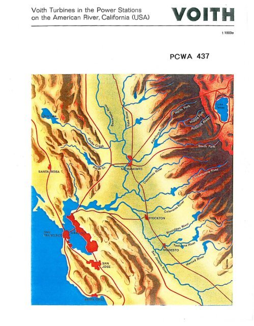
Voith Turbines in the Power Stations<br />
on the <strong>American</strong> <strong>River</strong>, California (USA) YOIIM<br />
<strong>PCWA</strong> 437<br />
t 1900.
Fig. 6 Installation of the spiral casing in the French<br />
Meadows Power Station.<br />
Fig. 7 Looking down the turbine pit of the French Meadows<br />
Power Station. In the right Foreground. the servomotor<br />
linkage driving the gate operating ring.<br />
5
<strong>Middle</strong> <strong>Fork</strong> Power Station<br />
The <strong>Middle</strong> <strong>Fork</strong> Power station utilizes the differential head<br />
between the Hell Hole reservoir and the small reservoir of the<br />
<strong>Middle</strong> <strong>Fork</strong> Power Station on the <strong>American</strong> <strong>River</strong>.<br />
Fig. 8 shows a section through this power station. Two<br />
vertical-shaft 6-jet Pelton turbines are connected to a penstock.<br />
Turbine data:<br />
head<br />
water discharge<br />
speed<br />
output<br />
1,832 It<br />
438 cfs<br />
400 rpm<br />
61,200 kW<br />
General design of the turbine<br />
(559 m)<br />
(12.48 m'/sec)<br />
The inlet casing, inlet diameter 43slu" (1,100 mm) Is embedded<br />
in concrete; welded of steel plates, it consists of 6 sections<br />
connected through welding·neck flanges; 5 of these<br />
sections have branches which lead to the nozzles.<br />
The aeration piping with hydraulically controlled valve is<br />
embedded in concrete above the inlet casing.<br />
The Pelton runner of chrome cast-steel is integral cast with<br />
23 buckets.<br />
The turbine shaft, forged of steel, has two flanges for<br />
connection with the runner and the generator shaft In the<br />
shaft flange and the runner hub a key is fitted to transmit the<br />
torque.<br />
The turbine housing, welded of steel plates, is shaped to<br />
provide favourable flow conditions for the water on<br />
its passage from the buckets into the tailrace. At the points<br />
where the nozzles project into the interior of the housing,<br />
a cone construction stiffens the housing. Air pipes terminating<br />
underneath the nozzles aerate the turbine housing when<br />
the equipment is in operation.<br />
The turbine pit is steel-plate lined. A door In the lateral wall<br />
gives access to an inspection grating Fitted underneath the<br />
runner for convenient inspection.<br />
The self-lubricating gUide bearing of the shaft is<br />
accommodated In the upper portion of the turbine housing;<br />
a separate oil cooler has been installed.<br />
The nozzles have renewable nozzle tips, the needle tips are<br />
also renewable. The needles are controlled from the<br />
outside. All parts subject to erosion are protected by a hardchromium<br />
layer. Compensating pistons and compensating<br />
springs are combined to obtain a closing tendency of the<br />
power needles. The needles are controlled by double-acting<br />
servomotors. The needle stem is additionally supported<br />
midway to provide against vibration. When the nozzles are<br />
being closed, the discharging all is throttled to keep the<br />
6<br />
Fig. 8 Section through <strong>Middle</strong> <strong>Fork</strong> Power Station with<br />
2 vertical-shaft 6·jet Pelton turbines and generators in semioutdoor<br />
arrangement.<br />
closing speed and thus the pressure rise in the penstock<br />
within the prescribed limits.<br />
Each power nozzle has a jet deflector which cuts into the<br />
power jet in the event of sudden load rejection. The deflector<br />
edge, made of 13% chrome cast-steel, is renewable. AI<br />
jet deflectors are interconnected through a linkage anl. ... (e<br />
operated by means of a double-acting pressure-oil servomotor.<br />
For emergency shutdown, a pressure·water<br />
servomotor is additionally available. A grease·lubricating<br />
pump automatically supplies the lubricating requirements of<br />
the bearings of the deflector shafts and the needle stems.<br />
Shaft seals<br />
A splash-water seal is fitted which consists of several<br />
labyrinths in series; furthermore, a standstill seal with a<br />
rubber diaphragm is provided which is pressed by<br />
compressed air against the shaft flange at the runner end.<br />
For subsequent operation of the equipment at a higher<br />
water level, a Sliding ring seal will be fitted.<br />
Shut-off valve<br />
Upstream of the inlet casing, a spherical valve has been<br />
installed with a body which is split at right angles to the axis<br />
outside the bearing points (nominal width of the spherical<br />
valve 43'1.. [1,100 mm], overalllen9th 70'1,," [1,789 mm)).<br />
Valve body and plug consist of cast steel, the trunnions of<br />
the plug are made of forged steel. Pressure water taken from<br />
the penstock is used to press the sealing plate against a<br />
seal on the downstream portion of the valve body, whereas<br />
upstream a maintenance seal allows renewal of the main<br />
seal of the spherical valve without the necessity of<br />
emptying the penstock. The plug of the spherical valve is<br />
operated by a double·acting rack·type pressure-water<br />
servomotor attached to the body of the spherical valve<br />
Opening of the spherical valve requires balanced preSb", e<br />
conditions, and for this purpose, a bypass Is prOVided. The<br />
spherical valve can, however, close against the full water<br />
flow and the full unilateral pressure.
f the two 6 -) °et<br />
. lhrough one 0 wer Station.<br />
Fig. . fO Horizontal b' es installe secdtlon In the M;ddle servomotor <strong>Fork</strong> Pdorive is ;nstalled<br />
Pelton tur In 'th rack-type<br />
. [valve WI .<br />
A sphenca ck and turbine.<br />
between<br />
peosta<br />
8
Fig. 11 "<strong>Middle</strong> <strong>Fork</strong>" inletcasing<br />
assembly in our large<br />
turbine hall. The nozzles with the<br />
needle drives as well as the jet<br />
deflectors have akeady been<br />
mounted.<br />
Fig. 12 One of the "<strong>Middle</strong> <strong>Fork</strong>"<br />
Pelton n..:nners with finished<br />
wheel disk and buckets.
12<br />
I<br />
f----------1-7315----------1<br />
III<br />
I IIII<br />
I I<br />
I<br />
I I<br />
Fig. 16 Horizontal section through<br />
the 6-jet -Ralston" Pelton turbine.<br />
Bottom left, the spherical valve with<br />
double-acting rack·type servomotor<br />
drive.<br />
y \IlIa
Fig. 21 Spherical valve as shut-off valve upstream of the "Ralston" turbine. At the left. the double-acting rack-type<br />
servomotor, which in either direction ;s operated by pressure water.<br />
Fig. 22 The 6 nozzle bodies with the attached nozzle tips for the"Ralston" turbine.<br />
16
Oxbow Power Station<br />
ThiS power station utilizes the differentIal head<br />
between the storage reservoir and the "<strong>Middle</strong> <strong>Fork</strong>"<br />
reservoir on the <strong>American</strong> <strong>River</strong> downstream of<br />
the power station. In the Oxbow Power Station,<br />
a vertical-shaft Francis spiral turbine has been<br />
installed which receives the operating water through<br />
a short penstock.<br />
Turbine data<br />
head<br />
water discharge<br />
speed<br />
output<br />
87 ft<br />
995 cfs<br />
200 rpm<br />
6,550 kW<br />
General design of the turbine<br />
(26,5 m)<br />
(28.2 m'!sec)<br />
The spiral casing, inlet diameter 108" (2,744 mm), is welded<br />
. of steel plates and is embedded in concrete. Turbine head<br />
cover and curb ring consist of cast steel; they are lined with<br />
stainless steel in the wicket-gate zone.<br />
20 cast-steel wicket-gates; their sealing edges are made af<br />
stainless steel. The wicket-gate stems are supported in<br />
bronze bushings. The wicket-gate levers are split and<br />
connected through breakage bolts.<br />
The 13% cast·steel Francis runner Is flanged onto the turbine<br />
shaft and coupled by fitted bolts. The mean inlet diameter is<br />
7B" (1,9S0 mm). Renewable chrome·steel wearing rings are<br />
fitted on runner crown and runner band.<br />
The shaft seal is of the sliding-ring type with carbon rings.<br />
The turbine shaft is supported in a self-lubricating bearing<br />
and has flanges for connection to the runner and the<br />
generator shaft. The bearing oil is cooled by an oil cooler.<br />
Various measuring Instruments read pressure and<br />
temperature of the bearing oil.<br />
The bend of the draft tube consists of a steel·plate liner,<br />
while the horizontal portkm is embedded in concrete. Underneath<br />
the runner, a manhole allows inspection of the runner.<br />
The draft tube is aerated by pipes run in the interior of the<br />
draft tube. The aeration pipes are opened and closed<br />
by valves operated by pressure oil. A pipe branches off at the<br />
spiral casing and leads to a dispersion valve, which is used<br />
as pressure regulator and bypass outlet.<br />
The dispersion valve is accommodated in a stilling chamber<br />
and discharges above one of the draft tube halves of the<br />
Francis turbine. To ensure that<br />
18<br />
r-- , .<br />
,';<br />
'--'-<br />
"<br />
Flg.25 Section through the Oxbow Power Station with a<br />
Francis spiral turbine from which a branch leads to a<br />
dispersion valve.<br />
1. the operation of the turbine is not adversely affected<br />
when turbine and dispersion valve operate simultaneously<br />
at part load and<br />
2. satisfactory dissIpation of the energy is achieved when<br />
the dispersion valve operates at full load at any tailwater<br />
level,<br />
model tests have been conducted in our Hydraulic Research<br />
Laboratory, where the optimum aeration conditions have been<br />
determined. On the basis of the model test results, the shape<br />
and dimensions of the stilling chamber have been finalized.<br />
Fig.26 Model of turbine bypass (scale 1 : 10) in our<br />
Hydraulic Research Laboratory.
Fig.29 Installation of the s prral . casing in th e •a<br />
xbow Power Station<br />
Top centr<br />
e, connection .<br />
_:<br />
pOint of penstock.<br />
Flg.30 axbo<br />
rotor has beenWlifted Power bySt thae rIon<br />
crane. nearing campiet· Ion. The cov<br />
er clOSing off the ope nrng . for the instalJation of the generator<br />
V.llB7f,