Anthony Catalano - EEWeb
Anthony Catalano - EEWeb
Anthony Catalano - EEWeb

Create successful ePaper yourself
Turn your PDF publications into a flip-book with our unique Google optimized e-Paper software.
PROJECT<br />
The Important Role of Drive Current on<br />
Lumen Maintenance<br />
The drive current of the LED plays an important role in<br />
determining Lumen maintenance. As discussed at the<br />
outset of this article, recombination in the semiconductor<br />
leads to the multiplication of defects and a reduction<br />
of the radiative efficiency. So it stands to reason that<br />
drive current must play an important role in Lumen<br />
depreciation. Unfortunately, no current standards<br />
recommend testing in this regime, and it is left to the<br />
LED manufacturer to choose the values of current used<br />
in testing. Fortunately, the top-tier manufacturers have<br />
chosen wisely and substantial data is available.<br />
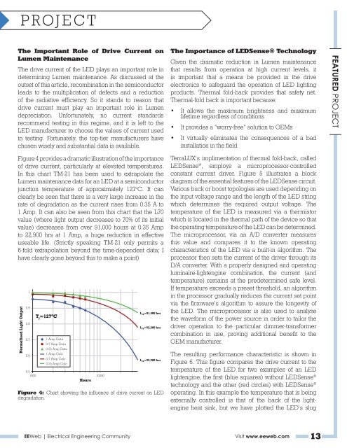
Figure 4 provides a dramatic illustration of the importance<br />
of drive current, particularly at elevated temperatures.<br />
In this chart TM-21 has been used to extrapolate the<br />
Lumen maintenance data for an LED at a semiconductor<br />
junction temperature of approximately 127 o C. It can<br />
clearly be seen that there is a very large increase in the<br />
rate of degradation as the current rises from 0.35 A to<br />
1 Amp. It can also be seen from this chart that the L70<br />
value (where light output decreases to 70% of its initial<br />
value) decreases from over 91,000 hours at 0.35 Amp<br />
to 22,900 hrs at 1 Amp, a huge reduction in effective<br />
useable life. (Strictly speaking TM-21 only permits a<br />
6-fold extrapolation beyond the time-dependent data; I<br />
have clearly gone beyond this to make a point)<br />
Normalised Light Output<br />
1<br />
0.9<br />
0.8<br />
0.7<br />
0.6<br />
T j ≈127ºC<br />
1 Amp Data<br />
0.7 Amp Data<br />
0.35 Amp Data<br />
1 Amp Calc<br />
0.7 Amp Calc<br />
0.35 Amp Calc<br />
0.5<br />
1000 10000<br />
Hours<br />
L 70 =91,400 hrs<br />
L 70 =52,200 hrs<br />
L 70 =22,290 hrs<br />
Figure 4: Chart showing the influence of drive current on LED<br />
degradation.<br />
The Importance of LEDSense® Technology<br />
Given the dramatic reduction in Lumen maintenance<br />
that results from operation at high current levels, it<br />
is important that a means be provided in the drive<br />
electronics to safeguard the operation of LED lighting<br />
products. Thermal fold-back provides that safety net.<br />
Thermal-fold back is important because:<br />
• It allows the maximum brightness and maximum<br />
lifetime regardless of conditions<br />
• It provides a “worry-free” solution to OEMs<br />
• It virtually eliminates the consequences of a bad<br />
installation in the field<br />
TerraLUX’s implimentation of thermal fold-back, called<br />
LEDSense ® , employs a microprocessor-controlled<br />
constant current driver. Figure 5 illustrates a block<br />
diagram of the essential features of the LEDSense circuit.<br />
Various buck or boost topologies are used depending on<br />
the input voltage range and the length of the LED string<br />
which determines the required output voltage. The<br />
temperature of the LED is measured via a thermistor<br />
which is located in the thermal path of the device so that<br />
the operating temperature of the LED can be determined.<br />
The microprocessor, via an A/D converter measures<br />
this value and compares it to the known operating<br />
characteristics of the LED via a built-in algorithm. The<br />
processor then sets the current of the driver through its<br />
D/A converter. With a properly designed and operating<br />
luminaire-lightengine combination, the current (and<br />
temperature) remains at the predetermined safe level.<br />
If temperature exceeds a preset threshold, an algorithm<br />
in the processor gradually reduces the current set point<br />
via the firmware’s algorithm to assure the longevity of<br />
the LED. The microprocessor is also used to analyze<br />
the waveform of the power source in order to tailor the<br />
driver operation to the particular dimmer-transformer<br />
combination in use, proving additional benefit to the<br />
OEM manufacturer.<br />
The resulting performance characteristic is shown in<br />
Figure 6. This figure compares the drive current to the<br />
temperature of the LED for two examples of an LED<br />
lightengine, the first (blue squares) without LEDSense ®<br />
technology and the other (red circles) with LEDSense ®<br />
operating. In this example the temperature that is being<br />
externally controlled is that of the back of the light-<br />
engine heat sink, but we have plotted the LED’s slug<br />
<strong>EEWeb</strong> | Electrical Engineering Community Visit www.eeweb.com 13<br />
FEATURED PROJECT