OTL101C Line Voltage Thermostat (°C)
OTL101C Line Voltage Thermostat (°C)
OTL101C Line Voltage Thermostat (°C)

You also want an ePaper? Increase the reach of your titles
YUMPU automatically turns print PDFs into web optimized ePapers that Google loves.
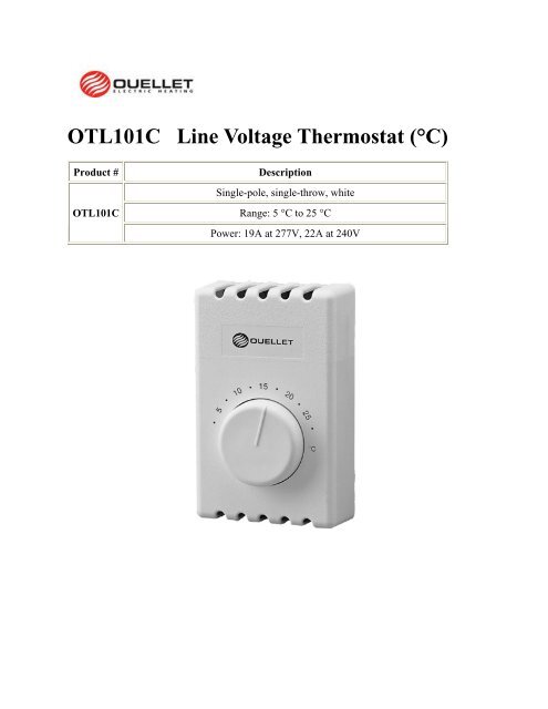
<strong>OTL101C</strong> <strong>Line</strong> <strong>Voltage</strong> <strong>Thermostat</strong> (<strong>°C</strong>)<br />
Product # Description<br />
<strong>OTL101C</strong><br />
Single-pole, single-throw, white<br />
Range: 5 <strong>°C</strong> to 25 <strong>°C</strong><br />
Power: 19A at 277V, 22A at 240V
T822<br />
Models<br />
F29<br />
Rectangular <strong>Thermostat</strong><br />
with Mercury Bulb<br />
Product # Color Range Description<br />
T822D2550 White<br />
T822D1024 Beige<br />
Universal Guard<br />
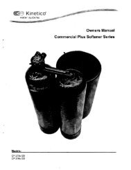
RT850 Electronic Triac Relay RC840<br />
The all in one solution. Silent operation, optimum regulation<br />
when combined with a pulsing proportional thermostat. Integrated<br />
or non integrated 24V transformer as well as indicator<br />
light to see at a glance whether the triac relay is on. Can control<br />
power levels of 23A and 208V/240V/277V/347V.<br />
Models<br />
Adjustable mercury bulb<br />
10 <strong>°C</strong> to 30 <strong>°C</strong> anticipator 1A max.<br />
(50 °F to 86 °F) (controls up to 5 relays<br />
without transformer)<br />
Product # <strong>Voltage</strong> 60 Hz Resistive charge (A) Input signal<br />
Without transformer (pulsing)<br />
RT850<br />
120/208/240<br />
347<br />
23<br />
23<br />
24VAC and<br />
4 to 32VDC<br />
With transformer<br />
RT850T-240 208/240 23 24VAC<br />
RT850T-347 347 23 24VAC<br />
OTL101<br />
Models<br />
Model<br />
Product # Description<br />
F29-0143<br />
Models<br />
<strong>Line</strong> <strong>Voltage</strong> <strong>Thermostat</strong><br />
Product # Power Range Description<br />
<strong>OTL101C</strong> 19A at 277V 5 <strong>°C</strong> to 25 <strong>°C</strong> Single-pole, single-throw,<br />
OTL101F 22A at 240V 40 °F to 75 °F white<br />
Protects both line and low voltage thermostats<br />
against vandalism, damage and unauthorized<br />
temperature settings<br />
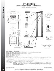
Conventional On/Off Relay<br />
Product # <strong>Voltage</strong> 60 Hz Resistive charge (A)<br />
Without transformer<br />
120 22<br />
RC840<br />
208/240 22<br />
347 18<br />
R841D1028<br />
With transformer<br />
600 10<br />
24A05A-1 120 25<br />
RC840T-240 208/240 22<br />
RC840T-277 277 19<br />
RC840T-347 347 18<br />
R841C1151 600 10<br />
NOTE: Not recommended for fast-cycling modulated regulation (less than 6 cycles/h).<br />
For fast-cycling heating equipment, we recommend the RT850 or RT850T (integrated<br />
24V transformer) Solid State Relay.<br />
www.ouellet.com • Edition 6.1.2 73
GENERAL<br />
The T410A,B Electric Heat <strong>Thermostat</strong>s provide line voltage<br />
control of electric heating equipment. Snap-action switch<br />
makes heating circuit on temperature fall.<br />
Copyright © 1996 Honeywell Inc. • • All Rights Reserved X-XX UL<br />
T410A,B<br />
Electric Heat <strong>Thermostat</strong>s<br />
FEATURES<br />
• Energy efficient and economical.<br />
• UL listed up to 5 kW at 277 Vac.<br />
PRODUCT DATA<br />
• Includes long-lasting Micro Switch mechanism.<br />
• Rugged, plastic mounting base; one-piece cover.<br />
• Contemporary white finish complements any decor.<br />
• Replaces virtually any wall-mounted electric heating<br />
thermostat.<br />
Contents<br />
General ............................................................................. 1<br />
Features ............................................................................ 1<br />
Specifications .................................................................... 2<br />
Ordering Information ......................................................... 2<br />
Installation ......................................................................... 3<br />
Settings and Checkout ...................................................... 4<br />
68-0145-2
T410A,B ELECTRIC HEAT THERMOSTATS<br />
SPECIFICATIONS<br />
IMPORTANT<br />
The Specifications given in this publication do not<br />
include normal manufacturing tolerances. Therefore,<br />
this unit may not exactly match the listed<br />
specifications. Also, this product is tested and<br />
calibrated under closely controlled conditions, and<br />
some minor differences in performance can be<br />
expected if those conditions are changed. For exact<br />
engineering specifications, contact your Honeywell<br />
sales representative.<br />
Models:<br />
T410A Electric Heating <strong>Thermostat</strong>: Spst switching;<br />
heating circuit makes on temperature fall.<br />
T410B Electric Heating <strong>Thermostat</strong>: Dpst switching; makes<br />
double line break with setting dial at OFF position;<br />
heating circuit makes on temperature fall.<br />
Electrical Ratings (Noninductive Resistive Rating):<br />
22A at 120/208/240 Vac; 19A at 277 Vac.<br />
Wiring Connections:<br />
6 in. (150 mm) copper leadwires, suitable for connecting to<br />
aluminum wiring if approved CO/ALR solderless wire<br />
connectors are used.<br />
Sensing Element:<br />
Bimetal.<br />
Setpoint Adjustment:<br />
Setting dial on the face of the thermostat.<br />
Temperature Range:<br />
40° to 80°F (5° to 25<strong>°C</strong>).<br />
Differential:<br />
3°F (2<strong>°C</strong>), nonadjustable.<br />
Switching:<br />
Micro Switch snap-acting switch.<br />
ORDERING INFORMATION<br />
68-0145—2 2<br />
Mounting:<br />
Mounts directly on NEMA standard 2 x 4 in. vertical outlet<br />
box, or 4 x 4 in. outlet box if used with ring adapter (ordered<br />
separately), using 6-32 Robertson slotted screws.<br />
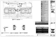
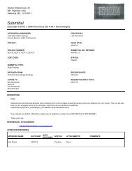
Dimensions:<br />
See Fig.1.<br />
Approvals:<br />
Underwriters Laboratories Inc. Listed: File No. E47434,<br />
Guide No. XAPX.<br />
Canadian Standards Association Certified: File No.<br />
LR1322.<br />
Accessory:<br />
272804A Range Stop and Locking Cover Assembly: Includes<br />
locking cover screws, Tinnerman clips, wrench and range<br />
stops—two plastic pins to insert inside cover for fieldselection<br />
of minimum and maximum temperature settings.<br />
FRONT VIEW SIDE VIEW<br />
• 40 • 50 • 60 • 70 • 80 •<br />
2-3/4 (70)<br />
˚F<br />
4-1/2<br />
(115)<br />
1-1/2 (38) 3/4<br />
(19)<br />
1-1/8 (29)<br />
5/8 (14)<br />
2-1/8<br />
(54)<br />
3-5/16<br />
(83)<br />
1-3/8<br />
(35)<br />
M5802A<br />
Fig. 1. T410 approximate dimensions in in. (mm).<br />
When purchasing replacement and modernization products from your TRADELINE® wholesaler or distributor, refer to the<br />
TRADELINE® Catalog or price sheets for complete ordering number or specify:<br />
1. Model Number.<br />
2. Switching.<br />
If you have additional questions, need further information, or would like to comment on our products or services, please write or<br />
phone:<br />
1. Your local Home and Building Control Sales Office (check white pages of your phone directory).<br />
2. Home and Building Control Customer Relations<br />
Honeywell, 1885 Douglas Drive North<br />
Minneapolis, Minnesota 55422-4386<br />
In Canada—Honeywell Limited/Honeywell Limitée, 35 Dynamic Drive, Scarborough, Ontario M1V 4Z9.<br />
International Sales and Service Offices in all principal cities of the world. Manufacturing in Australia, Canada, Finland, France,<br />
Germany, Japan, Mexico, Netherlands, Spain, Taiwan, United Kingdom, U.S.A.
RECYCLING NOTICE<br />
If this control is replacing a control that contains<br />
mercury in a sealed tube, do not place your old<br />
control in the trash.<br />
Contact your local waste management authority for<br />
instructions regarding recycling and the proper<br />
disposal of any control containing mercury in a<br />
sealed tube.<br />
INSTALLATION<br />
When Installing this Product…<br />
1. Read these instructions carefully. Failure to follow these<br />
instructions could damage the product or cause a<br />
hazardous condition.<br />
2. Check the ratings on the product to make sure the<br />
product is suitable for your application.<br />
3. Installer must be a trained, experienced service<br />
technician.<br />
4. After installation is complete, check out product<br />
operation as provided in these instructions.<br />
WARNING<br />
HIGH VOLTAGE CONTROL.<br />
ELECTRICAL SHOCK HAZARD.<br />
Follow local codes and ordinances when installing this<br />
thermostat. Improper handling can cause serious<br />
injury or death.<br />
CAUTION<br />
1. Disconnect power supply to prevent electrical<br />
shock or equipment damage.<br />
2. When connecting with aluminum conductors, use<br />
CO/ALR solderless wire connectors to avoid fire<br />
hazard.<br />
3. To avoid damaging the sensing element, do not<br />
remove thermostat cover until wiring is complete.<br />
Location<br />
Install a vertical outlet box, which is used to mount the<br />
thermostat, about 5 ft (1.5 m) above the floor in an area with<br />
good air circulation at room temperature.<br />
Do not install the thermostat where it may be affected by:<br />
— drafts or dead spots behind doors, in corners or under<br />
cabinets.<br />
— hot air from convectors.<br />
— radiant heat from sun or appliances.<br />
— concealed pipes and chimneys.<br />
— unheated (uncooled) areas such as an outside wall<br />
behind the thermostat.<br />
3<br />
T410A,B ELECTRIC HEAT THERMOSTATS<br />
Wiring and Mounting<br />
CAUTION<br />
1. To avoid damaging the sensing element, handle<br />
the thermostat with care.<br />
2. Use a separate limit control in the heating<br />
appliance.<br />
3. To prevent damage to dial stop when mounting the<br />
thermostat, turn the temperature setting dial until<br />
the setpoint indicator is at the 12 o’clock position.<br />
Replacement Applications<br />
Disconnect power to the thermostat to prevent electrical<br />
shock or equipment damage. All wiring must comply<br />
with local electrical codes and ordinances.<br />
Remove the old thermostat from the wall, taking care<br />
not to damage the wiring insulation.<br />
Check the old wire insulation for cracks, nicks or fraying.<br />
If necessary, apply approved electrical tape to insulate<br />
old wires or replace with new wires.<br />
Do not remove the T410 <strong>Thermostat</strong> Cover. Using wire<br />
connectors approved for No. 12 wires, make line voltage<br />
connections directly to the leadwires on the thermostat.<br />
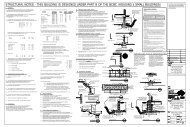
See Figs. 2 and 3 for typical wiring connections.<br />
Prebend and push solid wires into the outlet box.<br />
Remove thermostat cover by grasping the top and<br />
bottom cover edge and pulling it outward away from<br />
the thermostat base.<br />
Turn the temperature setting dial so the setpoint<br />
indicator is at the 12 o’clock position to prevent<br />
damaging the dial stop.<br />
Mount the thermostat on the outlet box. Tighten the two<br />
mounting screws (included) to secure the thermostat,<br />
taking care to avoid excessive pressure on the setting<br />
dial. See Fig. 4.<br />
1<br />
2<br />
3<br />
4<br />
1<br />
L1<br />
(HOT)<br />
L2<br />
SOLDERLESS<br />
CONNECTORS<br />
2<br />
T410A<br />
ELECTRIC<br />
HEATER<br />
POWER SUPPLY. PROVIDE DISCONNECT MEANS AND<br />
OVERLOAD PROTECTION AS REQUIRED.<br />
USE SPECIAL SERVICE CO/ALR SOLDERLESS CONNECTORS<br />
WHEN CONNECTING ALUMINUM CONDUCTORS OR A FIRE<br />
HAZARD MAY RESULT.<br />
USE A SEPARATE LIMIT CONTROL IN THE HEATING APPLIANCE.<br />
BREAKS AND REMAKES BELOW -31°F (-35<strong>°C</strong>); NORMALLY<br />
THERMAL ACTIVATED. BREAKS ON TEMPERATURE RISE;<br />
MAKES ON TEMPERATURE FALL.<br />
M5811B<br />
Fig. 2. Typical wiring connections for T410A.<br />
L1<br />
T1<br />
4<br />
3<br />
68-0145—2
T410A,B ELECTRIC HEAT THERMOSTATS<br />
1<br />
2<br />
3<br />
4<br />
5<br />
6<br />
1<br />
L2<br />
L1<br />
(HOT)<br />
Home and Building Control<br />
Honeywell Inc.<br />
1985 Douglas Drive North<br />
Golden Valley, MN 55422<br />
2<br />
3<br />
L1<br />
T1<br />
T410B<br />
SOLDERLESS<br />
CONNECTORS<br />
RED<br />
WIRE<br />
6<br />
ELECTRIC<br />
HEATER<br />
POWER SUPPLY. PROVIDE DISCONNECT MEANS AND<br />
OVERLOAD PROTECTION AS REQUIRED.<br />
USE SPECIAL SERVICE CO/ALR SOLDERLESS CONNECTORS<br />
WHEN CONNECTING ALUMINUM CONDUCTORS OR A FIRE<br />
HAZARD MAY RESULT.<br />
BREAKS AT POSITIVE OFF AND REMAKES UNDER –31°F (–35<strong>°C</strong>);<br />
NORMALLY THERMALLY ACTIVATED. BREAKS ON TEMPERATURE<br />
RISE; MAKES ON TEMPERATURE FALL.<br />
USE A SEPARATE LIMIT CONTROL IN THE HEATING APPLIANCE.<br />
BREAKS AT POSITIVE OFF ONLY; NOT THERMALLY ACTIVATED.<br />
DO NOT CONNECT GROUNDED CONDUCTOR (NEUTRAL) ON<br />
120 OR 227V CIRCUITS. INSULATE AND TAPE OR CUT OFF<br />
RED WIRES IF UNUSED.<br />
M5812B<br />
Fig. 3. Typical wiring connections for T410B.<br />
OUTLET<br />
BOX<br />
L2<br />
T2<br />
5<br />
WALL<br />
MOUNTING<br />
SCREWS (2)<br />
Home and Building Control<br />
Honeywell Limited-Honeywell Limitée<br />
155 Gordon Baker Road<br />
North York, Ontario<br />
M2H 2C9<br />
Printed on recycled paper containing at<br />
68-0145—2 C.H. Rev. 4-96 Printed in U.S.A.<br />
least 4 10% post-consumer paper fibers.<br />
4<br />
THERMOSTAT<br />
BASE<br />
M5803<br />
Fig. 4. Mounting thermostat on outlet box.<br />
New Applications<br />
Disconnect power supply to prevent electrical shock or<br />
equipment damage. All wiring must comply with local<br />
electrical codes and ordinances.<br />
Run line voltage wiring to the thermostat location.<br />
Do not remove the T410 <strong>Thermostat</strong> Cover. Using wire<br />
connectors approved for No. 12 wires, make line<br />
voltage connections directly to the leadwires on the<br />
thermostat. See Figs. 2 and 3 for typical wiring<br />
connections.<br />
Prebend and push solid wires into the outlet box.<br />
Remove the thermostat cover by grasping the top and<br />
bottom cover edge and pulling it outward away from the<br />
thermostat base.<br />
Turn the temperature setting dial so the setpoint<br />
indicator is at the 12 o’clock position to prevent<br />
damaging the dial stop.<br />
Mount the thermostat on the outlet box. Tighten the two<br />
mounting screws (included) to secure the thermostat,<br />
taking care to avoid excessive pressure on the setting<br />
dial. See Fig.4.<br />
SETTINGS AND CHECKOUT<br />
Setting<br />
The thermostat temperature setting can be adjusted by<br />
turning the setting dial clockwise or counterclockwise to the<br />
desired setting. See Fig. 5. To determine appropriate setting,<br />
allow the thermostat to operate for several hours.<br />
Checkout<br />
IMPORTANT<br />
Make sure all wiring connections are tight before<br />
proceeding with Checkout.<br />
Check out thermostat operation as follows:<br />
Turn the setting dial fully clockwise; heating circuit<br />
makes and electric heater starts.<br />
Turn the setting dial fully counterclockwise; the heating<br />
circuit breaks and the heater starts to cool.<br />
• 40 • 50 • 60 • 70 • 80 •<br />
˚F<br />
TURN SETTING DIAL<br />
CLOCKWISE OR COUNTER-<br />
CLOCKWISE TO ADJUST<br />
TEMPERATURE SETTING.<br />
M5804<br />
Fig. 5. Adjusting temperature setpoint.<br />
Helping You Control Your World<br />
www.honeywell.com/yourhome