MdMUTCD 2006 - Maryland State Highway Administration
MdMUTCD 2006 - Maryland State Highway Administration
MdMUTCD 2006 - Maryland State Highway Administration

You also want an ePaper? Increase the reach of your titles
YUMPU automatically turns print PDFs into web optimized ePapers that Google loves.
95<br />
MARYLAND<br />
MManual ontrol<br />
on UUniform<br />
for Streets and <strong>Highway</strong>s<br />
TTraffic for Streets<br />
CControl and <strong>Highway</strong>s<br />
DDevices<br />
for Streets and <strong>Highway</strong>s<br />
<strong>2006</strong> Edition<br />
Including Revision 1 dated July 2009<br />
<strong>Maryland</strong> <strong>State</strong><br />
<strong>Highway</strong> <strong>Administration</strong>
<strong>2006</strong> Edition Page i<br />
The Manual on Uniform Traffic Control Devices (MUTCD) is approved by the Federal <strong>Highway</strong> Administrator<br />
as the National Standard in accordance with Title 23 U.S. Code, Sections 109(d), 114(a), 217, 315, and 402(a),<br />
23 CFR 655, and 49 CFR 1.48(b)(8), 1.48(b)(33), and 1.48(c)(2).<br />
Addresses for Publications Referenced in the MUTCD<br />
American Association of <strong>State</strong> <strong>Highway</strong> and<br />
Transportation Officials (AASHTO)<br />
444 North Capitol Street, NW, Suite249<br />
Washington, DC 20001<br />
www.transportation.org<br />
American Railway Engineering and<br />
Maintenance-of-Way Association (AREMA)<br />
8201 Corporate Drive, Suite 1125<br />
Landover, MD 20785-2230<br />
www.arema.org<br />
Federal <strong>Highway</strong> <strong>Administration</strong> Report Center<br />
Facsimile number: 301.577.1421<br />
report.center@fhwa.dot.gov<br />
Illuminating Engineering Society (IES)<br />
120 Wall Street,Floor 17<br />
NewYork, NY 10005<br />
www.iesna.org<br />
Institute of Makers of Explosives<br />
1120 19th Street, NW, Suite310<br />
Washington, DC 20036-3605<br />
www.ime.org<br />
Institute of Transportation Engineers (ITE)<br />
1099 14th Street, NW, Suite300 West<br />
Washington, DC 20005-3438<br />
www.ite.org<br />
International Organization for Standards<br />
c/o Mr. Gerard Kuso<br />
Austrian Standards Institute<br />
Heinestrabe 38<br />
Postfach 130<br />
A-1021<br />
Wien, Austria<br />
www.iso.ch<br />
ISEA - The Safety Equipment Association<br />
1901 North Moore Street, Suite 808<br />
Arlington, VA 22209<br />
www.safetyequipment.org<br />
<strong>Maryland</strong> <strong>State</strong> <strong>Highway</strong> <strong>Administration</strong> (MSHA)<br />
707 North Calvert Street<br />
Baltimore, MD21202<br />
www.sha.state.md.us<br />
<strong>Maryland</strong> <strong>State</strong> <strong>Highway</strong> <strong>Administration</strong>’s<br />
Office of Traffic and Safety (OOTS)<br />
Traffic Development and Support Division (TDSD)<br />
Traffic Engineering Design Division (TEDD)<br />
7491 Connelley Drive<br />
Hanover, MD 21076<br />
www.sha.state.md.us<br />
National Committee on Uniform Traffic Laws<br />
and Ordinances (NCUTLO)<br />
107 South West Street, Suite110<br />
Alexandria, VA 22314<br />
www.ncutlo.org<br />
Occupational Safety and Health <strong>Administration</strong> (OSHA)<br />
U.S. Department of Labor<br />
200 Constitution Avenue, NW<br />
Washington, DC 20210<br />
www.osha.gov
Page ii <strong>2006</strong> Edition<br />
Transportation Research Board (TRB)<br />
The National Academies<br />
2101 Constitution Avenue, NW<br />
Washington, DC 20418<br />
www.nas.edu/trb<br />
U.S. Architectural and Transportation Barriers<br />
Compliance Board (The U.S. Access Board)<br />
1331 F Street, NW, Suite 1000<br />
Washington, DC 20004-1111<br />
www.access-board.gov<br />
Acknowledgments<br />
The Federal <strong>Highway</strong> <strong>Administration</strong> gratefully acknowledges the valuable assistance that it received from the<br />
National Committee on Uniform Traffic Control Devices and its over 200 voluntary members in the development<br />
of this Manual.<br />
Notes<br />
07/09<br />
The blue text identifies modifications or additions to the Federal MUTCD. The text is identified throughout the<br />
<strong>MdMUTCD</strong> as Standard, Guidance or Option based on the application. Modifications to existing figures and<br />
table identified with blue text apply throughout the state of <strong>Maryland</strong> and applies to all road systems in the state<br />
except where noted in the text.<br />
The SHA logos are placed solely when deletions were made to the text or to indicate where the modifications are<br />
made to the figures and tables of Federal MUTCD.<br />
Legends<br />
Indicates where modifications, additions or deletions were made with regards to the text, figures, or<br />
tables of the Federal MUTCD during the creation of, or revision to, the <strong>MdMUTCD</strong> and unless otherwise<br />
noted this applies to all roadways in <strong>Maryland</strong>.<br />
xx/xx Date Revision Issued
<strong>2006</strong> Edition Page TC-1<br />
INTRODUCTION<br />
PART 1. GENERAL<br />
Chapter 1A. General<br />
MANUAL ON UNIFORM TRAFFIC CONTROL DEVICES<br />
TABLE OF CONTENTS<br />
PART 2. SIGNS<br />
Chapter 2A. General<br />
Chapter 2B. Regulatory Signs<br />
Chapter 2C. Warning Signs<br />
Chapter 2D. Guide Signs — Conventional Roads<br />
Chapter 2E. Guide Signs — Freeways and Expressways<br />
Chapter 2F. Specific Service Signs<br />
Chapter 2G. Tourist-Oriented Directional Signs<br />
Chapter 2H. Recreational and Cultural Interest Area Signs<br />
Chapter 2I. Emergency Management Signing<br />
PART 3. MARKINGS<br />
Chapter 3A. General<br />
Chapter 3B. Pavement and Curb Markings<br />
Chapter 3C. Object Markers<br />
Chapter 3D. Delineators<br />
Chapter 3E. Colored Pavements<br />
Chapter 3F. Barricades and Channelizing Devices<br />
Chapter 3G. Islands<br />
PART 4. HIGHWAY TRAFFIC SIGNALS<br />
Chapter 4A. General<br />
Chapter 4B. Traffic Control Signals — General<br />
Chapter 4C. Traffic Control Signal Needs Studies<br />
Chapter 4D. Traffic Control Signal Features<br />
Chapter 4E. Pedestrian Control Features<br />
Chapter 4F. Traffic Control Signals for Emergency Vehicle Access<br />
Chapter 4G. Traffic Control Signals for One-Lane, Two-Way Facilities<br />
Chapter 4H. Traffic Control Signals for Freeway Entrance Ramps<br />
Chapter 4I. Traffic Control for Movable Bridges<br />
Chapter 4J. Lane-Use Control Signals<br />
Chapter 4K. Flashing Beacons<br />
Chapter 4L. In-Roadway Lights<br />
PART 5. TRAFFIC CONTROL DEVICES FOR LOW-VOLUME ROADS<br />
Chapter 5A. General<br />
Chapter 5B. Regulatory Signs<br />
Chapter 5C. Warning Signs<br />
Chapter 5D. Guide Signs<br />
Chapter 5E. Markings<br />
Chapter 5F. Traffic Control for <strong>Highway</strong>-Rail Grade Crossings<br />
Chapter 5G. Temporary Traffic Control Zones
Page TC-2 <strong>2006</strong> Edition<br />
PART 6. TEMPORARY TRAFFIC CONTROL<br />
Chapter 6A. General<br />
Chapter 6B. Fundamental Principles<br />
Chapter 6C. Temporary Traffic Control Elements<br />
Chapter 6D. Pedestrian and Worker Safety<br />
Chapter 6E. Flagger Control<br />
Chapter 6F. Temporary Traffic Control Zone Devices<br />
Chapter 6G. Temporary Traffic Control Zone Activities<br />
Chapter 6H. Typical Applications<br />
Chapter 6I. Control of Traffic Through Traffic Incident Management Areas<br />
PART 7. TRAFFIC CONTROLS FOR SCHOOL AREAS<br />
Chapter 7A. General<br />
Chapter 7B. Signs<br />
Chapter 7C. Markings<br />
Chapter 7D. Signals<br />
Chapter 7E. Crossing Supervision<br />
Chapter 7F. Grade-Separated Crossings<br />
PART 8. TRAFFIC CONTROLS FOR HIGHWAY-RAIL GRADE CROSSINGS<br />
Chapter 8A. General<br />
Chapter 8B. Signs and Markings<br />
Chapter 8C. Illumination<br />
Chapter 8D. Flashing-Light Signals, Gates, and Traffic Control Signals<br />
PART 9. TRAFFIC CONTROLS FOR BICYCLE FACILITIES<br />
Chapter 9A. General<br />
Chapter 9B. Signs<br />
Chapter 9C. Markings<br />
Chapter 9D. Signals<br />
PART 10. TRAFFIC CONTROLS FOR HIGHWAY-LIGHT RAIL TRANSIT<br />
GRADE CROSSINGS<br />
Chapter 10A. General<br />
Chapter 10B. <strong>Highway</strong>-Light Rail Transit Grade Crossing Control Systems<br />
Chapter 10C. Signs, Illumination, and Markings<br />
Chapter 10D. <strong>Highway</strong>-Light Rail Transit Active Traffic Control Grade Crossing Systems<br />
APPENDIX A1. CONGRESSIONAL LEGISLATION
95<br />
MARYLAND<br />
MManual on UUniform<br />
TTraffic CControl DDevices<br />
<strong>2006</strong> Edition<br />
Including Revision 1 dated July 2009<br />
Part 1<br />
General<br />
<strong>Maryland</strong> <strong>State</strong><br />
<strong>Highway</strong> <strong>Administration</strong>
<strong>2006</strong> Edition Page TC1-1<br />
PART 1. GENERAL<br />
TABLE OF CONTENTS<br />
CHAPTER 1A. GENERAL<br />
Section 1A.01 Purpose of Traffic Control Devices.........................................................................................1A-1<br />
Section 1A.02 Principles of Traffic Control Devices......................................................................................1A-1<br />
Section 1A.03 Design of Traffic Control Devices ..........................................................................................1A-2<br />
Section 1A.04 Placement and Operation of Traffic Control Devices .............................................................1A-2<br />
Section 1A.05 Maintenance of Traffic Control Devices.................................................................................1A-2<br />
Section 1A.06 Uniformity of Traffic Control Devices....................................................................................1A-3<br />
Section 1A.07 Responsibility for Traffic Control Devices .............................................................................1A-3<br />
Section 1A.08 Authority for Placement of Traffic Control Devices...............................................................1A-4<br />
Section 1A.09 Engineering Study and Engineering Judgment.......................................................................1A-4<br />
Section 1A.10 Interpretations, Experimentations, Changes, and Interim Approvals .....................................1A-4<br />
Section 1A.11 Relation to Other Publications ................................................................................................1A-8<br />
Section 1A.12 Color Code ............................................................................................................................1A-10<br />
Section 1A.13 Definitions of Words and Phrases in This Manual................................................................1A-11<br />
Section 1A.14 Abbreviations Used on Traffic Control Devices ...................................................................1A-15<br />
FIGURES<br />
CHAPTER 1A. GENERAL<br />
Figure 1A-1 Example of Process for Requesting and Conducting Experimentations for New<br />
Traffic Control Devices ...........................................................................................................1A-5<br />
Figure 1A-2 Example of Process for Incorporating New Traffic Control Devices into the<br />
MUTCD...................................................................................................................................1A-9<br />
TABLES<br />
CHAPTER 1A. GENERAL<br />
Table 1A-1 Acceptable Abbreviations......................................................................................................1A-16<br />
Table 1A-2 Abbreviations That Are Acceptable Only with a Prompt Word............................................1A-19<br />
Table 1A-2a Miscellaneous.......................................................................................................................1A-20<br />
Table 1A-3 Unacceptable Abbreviations..................................................................................................1A-20<br />
Page
<strong>2006</strong> Edition Page 1A-1<br />
CHAPTER 1A. GENERAL<br />
Section 1A.01 Purpose of Traffic Control Devices<br />
Support:<br />
The purpose of traffic control devices, as well as the principles for their use, is to promote highway safety<br />
and efficiency by providing for the orderly movement of all road users on streets and highways throughout<br />
the Nation.<br />
Traffic control devices notify road users of regulations and provide warning and guidance needed for the<br />
reasonably safe, uniform, and efficient operation of all elements of the traffic stream.<br />
Standard:<br />
Traffic control devices or their supports shall not bear any advertising message or any other message<br />
that is not related to traffic control.<br />
Support:<br />
Tourist-oriented directional signs and Specific Service signs are not considered advertising; rather, they are<br />
classified as motorist service signs.<br />
See Section 2A.07 Option and Support regarding safety or transportation related messages on changeable<br />
signs.<br />
Section 1A.02 Principles of Traffic Control Devices<br />
Support:<br />
This Manual contains the basic principles that govern the design and use of traffic control devices for all<br />
streets and highways open to public travel regardless of type or class or the public agency having jurisdiction.<br />
This Manual’s text specifies the restriction on the use of a device if it is intended for limited application or for a<br />
specific system. It is important that these principles be given primary consideration in the selection and<br />
application of each device.<br />
The basic principles contained in this Manual governing the design of traffic control devices also apply to<br />
devices along roads on private property that are open to the public (<strong>Maryland</strong> Vehicle Law Transportation<br />
Article Section 25-104).<br />
Guidance:<br />
To be effective, a traffic control device should meet five basic requirements:<br />
A. Fulfill a need;<br />
B. Command attention;<br />
C. Convey a clear, simple meaning;<br />
D. Command respect from road users; and<br />
E. Give adequate time for proper response.<br />
Design, placement, operation, maintenance, and uniformity are aspects that should be carefully considered in<br />
order to maximize the ability of a traffic control device to meet the five requirements listed in the previous<br />
paragraph. Vehicle speed should be carefully considered as an element that governs the design, operation,<br />
placement, and location of various traffic control devices and should be based on the most appropriate speed data<br />
available.<br />
Support:<br />
The definition of the word “speed” varies depending on its use. The definitions of specific speed terms are<br />
contained in Section 1A.13.<br />
Guidance:<br />
The actions required of road users to obey regulatory devices are specified by <strong>State</strong> statute, or in cases not<br />
covered by <strong>State</strong> statute, by local ordinance or resolution consistent with the <strong>Maryland</strong> Vehicle Law and the<br />
“Uniform Vehicle Code”.<br />
The proper use of traffic control devices should provide the reasonable and prudent road user with the<br />
information necessary to reasonably safely and lawfully use the streets, highways, pedestrian facilities, and<br />
bikeways.<br />
Support:<br />
Uniformity of the meaning of traffic control devices is vital to their effectiveness. The meanings ascribed to<br />
devices in this Manual are in general accord with the publications mentioned in Section 1A.11.<br />
Sect. 1A.01 to 1A.02
Page 1A-2 <strong>2006</strong> Edition<br />
Section 1A.03 Design of Traffic Control Devices<br />
Guidance:<br />
Devices should be designed so that features such as size, shape, color, composition, lighting or<br />
retroreflection, and contrast are combined to draw attention to the devices; that size, shape, color, and simplicity<br />
of message combine to produce a clear meaning; that legibility and size combine with placement to permit<br />
adequate time for response; and that uniformity, size, legibility, and reasonableness of the message combine to<br />
command respect.<br />
Standard:<br />
All symbols shall be unmistakably similar to or mirror images of the adopted symbol signs, all of<br />
which are shown in the “Standard <strong>Highway</strong> Signs” book or the <strong>Maryland</strong> Standard Sign Book (see<br />
Section 1A.11). Symbols and colors shall not be modified unless otherwise stated herein. All symbols<br />
and colors for signs not shown in the “Standard <strong>Highway</strong> Signs” book or the <strong>Maryland</strong> Standard Sign<br />
Book shall follow the procedures for experimentation and change described in Section 1A.10.<br />
Guidance:<br />
Aspects of a device’s design should be modified only if there is a demonstrated need.<br />
Support:<br />
An example of modifying a device’s design would be to modify the Side Road (W2-2) sign to show a second<br />
offset intersecting road.<br />
Option:<br />
<strong>Highway</strong> agencies may develop word message signs to notify road users of special regulations or to warn<br />
road users of a situation that might not be readily apparent. Unlike symbol signs and colors, new word message<br />
signs may be used without the need for experimentation. With the exception of symbols and colors, minor<br />
modifications in the specific design elements of a device may be made provided the essential appearance<br />
characteristics are preserved. Although the standard design of symbol signs cannot be modified, it may be<br />
appropriate to change the orientation of the symbol to better reflect the direction of travel.<br />
Section 1A.04 Placement and Operation of Traffic Control Devices<br />
Guidance:<br />
Placement of a traffic control device should be within the road user’s view so that adequate visibility is<br />
provided. To aid in conveying the proper meaning, the traffic control device should be appropriately positioned<br />
with respect to the location, object, or situation to which it applies. The location and legibility of the traffic<br />
control device should be such that a road user has adequate time to make the proper response in both day and<br />
night conditions.<br />
Traffic control devices should be placed and operated in a uniform and consistent manner.<br />
Unnecessary traffic control devices should be removed. The fact that a device is in good physical condition<br />
should not be a basis for deferring needed removal or change.<br />
Section 1A.05 Maintenance of Traffic Control Devices<br />
Standard:<br />
The maintenance of traffic control devices shall be considered whenever a decision is made to install<br />
such devices.<br />
Guidance:<br />
Functional maintenance of traffic control devices should be used to determine if certain devices need to be<br />
changed to meet current traffic conditions.<br />
Physical maintenance of traffic control devices should be performed to retain the legibility and visibility of<br />
the device, and to retain the proper functioning of the device.<br />
Support:<br />
Clean, legible, properly mounted devices in good working condition command the respect of road users.<br />
Sect. 1A.03 to 1A.05
<strong>2006</strong> Edition Page 1A-3<br />
Section 1A.06 Uniformity of Traffic Control Devices<br />
Support:<br />
Uniformity of devices simplifies the task of the road user because it aids in recognition and understanding,<br />
thereby reducing perception/reaction time. Uniformity assists road users, law enforcement officers, and traffic<br />
courts by giving everyone the same interpretation. Uniformity assists public highway officials through efficiency<br />
in manufacture, installation, maintenance, and administration. Uniformity means treating similar situations in a<br />
similar way. The use of uniform traffic control devices does not, in itself, constitute uniformity. A standard<br />
device used where it is not appropriate is as objectionable as a nonstandard device; in fact, this might be worse,<br />
because such misuse might result in disrespect at those locations where the device is needed and appropriate.<br />
Section 1A.07 Responsibility for Traffic Control Devices<br />
Standard:<br />
The responsibility for the design, placement, operation, maintenance, and uniformity of traffic control<br />
devices shall rest with the public agency or the official having jurisdiction. 23 CFR 655.603 adopts the<br />
Manual on Uniform Traffic Control Devices as the national standard for all traffic control devices installed<br />
on any street, highway, or bicycle trail open to public travel. When a <strong>State</strong> or other Federal agency<br />
manual or supplement is required, that manual or supplement shall be in substantial conformance with<br />
the national Manual on Uniform Traffic Control Devices.<br />
23 CFR 655.603 also states that traffic control devices on all streets and highways open to public travel<br />
in each <strong>State</strong> shall be in substantial conformance with standards issued or endorsed by the Federal<br />
<strong>Highway</strong> Administrator.<br />
Support:<br />
The “Uniform Vehicle Code” (see Section 1A.11) has the following provision in Section 15-104 for the<br />
adoption of a uniform Manual:<br />
“(a)The [<strong>State</strong> <strong>Highway</strong> Agency] shall adopt a manual and specification for a uniform system of traffic<br />
control devices consistent with the provisions of this code for use upon highways within this <strong>State</strong>. Such<br />
uniform system shall correlate with and so far as possible conform to the system set forth in the most<br />
recent edition of the Manual on Uniform Traffic Control Devices for Streets and <strong>Highway</strong>s, and other<br />
standards issued or endorsed by the Federal <strong>Highway</strong> Administrator.”<br />
“(b) The Manual adopted pursuant to subsection (a) shall have the force and effect of law.”<br />
Additionally, <strong>State</strong>s are encouraged to adopt Section 15-116 of the “Uniform Vehicle Code,” which states<br />
that, “No person shall install or maintain in any area of private property used by the public any sign, signal,<br />
marking or other device intended to regulate, warn, or guide traffic unless it conforms with the <strong>State</strong> manual and<br />
specifications adopted under Section 15-104.”<br />
<strong>Maryland</strong> Vehicle Law (MVL) Section TR 25-104 requires that the <strong>Maryland</strong> <strong>State</strong> <strong>Highway</strong> <strong>Administration</strong><br />
(MSHA) adopt a "manual and specifications for a uniform system of traffic control devices, consistent with the<br />
provisions of the <strong>Maryland</strong> Vehicle Law, for use on highways in this <strong>State</strong>." MSHA, via a Memorandum of<br />
Action (MOA), has adopted the MUTCD, this Supplement, the Standard <strong>Highway</strong>s Sign Book and <strong>Maryland</strong><br />
Supplement Sign Book, to fulfill this requirement. The Supplement addresses adaptations of the MUTCD to<br />
<strong>Maryland</strong>'s experience and sets out as standard what has been practice for some time.<br />
The Director’s Office of Traffic and Safety has, through the same Memorandum of Action (MOA), been<br />
directed by the <strong>Maryland</strong> <strong>State</strong> <strong>Highway</strong> <strong>Administration</strong> to distribute the MUTCD, and offer changes,<br />
experimentations, and interpretations regarding the traffic control devices described therein as may be appropriate<br />
under <strong>Maryland</strong> Law.<br />
Section TR 25-104.1 of the MVL prohibits anyone from selling or offering for sale any traffic control device<br />
that does not conform to the “<strong>State</strong> manual and specifications”.<br />
Section TR 25-105 of the MVL requires that traffic control devices installed on highways under the<br />
jurisdiction of the MSHA "shall conform to the manual and specifications of the <strong>State</strong> <strong>Highway</strong> <strong>Administration</strong>."<br />
Local authorities may place traffic control devices on such highways only with the permission and under the<br />
direction of the <strong>State</strong> <strong>Highway</strong> <strong>Administration</strong>.<br />
Section TR 25-106 of the MVL requires that traffic control devices placed by local authorities on streets and<br />
highways under their jurisdiction must also conform to the "manual and specifications of the <strong>State</strong> <strong>Highway</strong><br />
<strong>Administration</strong>."<br />
Section TR 25-106.1 of the MVL requires that traffic control devices placed along private roadways open to<br />
public must conform with the “<strong>State</strong> manual and specifications”.<br />
Sect. 1A.06 to 1A.07
Page 1A-4 <strong>2006</strong> Edition<br />
Section 1A.08 Authority for Placement of Traffic Control Devices<br />
Standard:<br />
Traffic control devices, advertisements, announcements, and other signs or messages within the<br />
highway right-of-way shall be placed only as authorized by a public authority or the official having<br />
jurisdiction, for the purpose of regulating, warning, or guiding traffic.<br />
When the public agency or the official having jurisdiction over a street or highway has granted proper<br />
authority, others such as contractors and public utility companies shall be permitted to install temporary<br />
traffic control devices in temporary traffic control zones. Such traffic control devices shall conform with<br />
the Standards of this Manual.<br />
Guidance:<br />
Any unauthorized traffic control device or other sign or message placed on the highway right-of-way by a<br />
private organization or individual constitutes a public nuisance and should be removed. All unofficial or<br />
nonessential traffic control devices, signs, or messages should be removed.<br />
Standard:<br />
All regulatory traffic control devices shall be supported by laws, ordinances, or regulations.<br />
Support:<br />
Provisions of this Manual are based upon the concept that effective traffic control depends upon both<br />
appropriate application of the devices and reasonable enforcement of the regulations.<br />
Reference Sections 21-205, 21-206, and 25-104 through 106.1 of Transportation Article of the <strong>Maryland</strong><br />
Code for general authority/responsiblility to place traffic control devices. Other sections of this Article reference<br />
more specific authorities/reponsibilities to place traffic control devices.<br />
Section 1A.09 Engineering Study and Engineering Judgment<br />
Standard:<br />
This Manual describes the application of traffic control devices, but shall not be a legal requirement<br />
for their installation.<br />
Guidance:<br />
The decision to use a particular device at a particular location should be made on the basis of either an<br />
engineering study or the application of engineering judgment. Thus, while this Manual provides Standards,<br />
Guidance, and Options for design and application of traffic control devices, this Manual should not be considered<br />
a substitute for engineering judgment.<br />
Engineering judgment should be exercised in the selection and application of traffic control devices, as well as<br />
in the location and design of the roads and streets that the devices complement. Jurisdictions with responsibility<br />
for traffic control that do not have engineers on their staffs should seek engineering assistance from others, such<br />
as the <strong>State</strong> transportation agency, their County, a nearby large City, or a traffic engineering consultant.<br />
Section 1A.10 Interpretations, Experimentations, Changes, and Interim Approvals<br />
Standard:<br />
Design, application, and placement of traffic control devices other than those adopted in this Manual<br />
shall be prohibited unless the provisions of this Section are followed.<br />
Support:<br />
Continuing advances in technology will produce changes in the highway, vehicle, and road user proficiency;<br />
therefore, portions of the system of traffic control devices in this Manual will require updating. In addition,<br />
unique situations often arise for device applications that might require interpretation or clarification of this<br />
Manual. It is important to have a procedure for recognizing these developments and for introducing new ideas<br />
and modifications into the system.<br />
Standard:<br />
The appropriate information regarding interpretation, permission to experiment, interim approval,<br />
and changes can be obtained from the <strong>Maryland</strong> <strong>State</strong> <strong>Highway</strong> <strong>Administration</strong>’s Office of Traffic and<br />
Safety, 7491 Connelley Drive, Hanover, MD 21076.<br />
Sect. 1A.08 to 1A.10
<strong>2006</strong> Edition Page 1A-5<br />
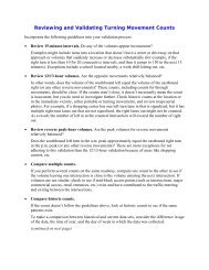
Figure 1A-1. Example of Process for Requesting and Conducting<br />
Experimentations for New Traffic Control Devices<br />
Evaluate<br />
experimental traffic<br />
control device<br />
Requesting jurisdiction<br />
submits request to<br />
<strong>Maryland</strong> <strong>State</strong><br />
<strong>Highway</strong> <strong>Administration</strong><br />
FHWA Review<br />
Approved?<br />
Yes<br />
Requesting jurisdiction<br />
installs experimental<br />
traffic control device<br />
Requesting jurisdiction<br />
provides FHWA a<br />
copy of final report<br />
through the <strong>Maryland</strong><br />
<strong>State</strong> <strong>Highway</strong><br />
<strong>Administration</strong><br />
No<br />
Requesting jurisdiction<br />
responds to questions<br />
raised by FHWA<br />
Requesting jurisdiction<br />
provides semi-annual<br />
reports to FHWA<br />
Division & HQ<br />
Sect. 1A.10
Page 1A-6 <strong>2006</strong> Edition<br />
Support:<br />
An interpretation includes a consideration of the application and operation of standard traffic control devices,<br />
official meanings of standard traffic control devices, or the variations from standard device designs.<br />
Guidance:<br />
Requests for an interpretation of this Manual should contain the following information:<br />
A. A concise statement of the interpretation being sought;<br />
B. A description of the condition that provoked the need for an interpretation;<br />
C. Any illustration that would be helpful to understand the request; and<br />
D. Any supporting research data that is pertinent to the item to be interpreted.<br />
Support:<br />
Requests to experiment include consideration of field deployment for the purpose of testing or evaluating a<br />
new traffic control device, its application or manner of use, or a provision not specifically described in this<br />
Manual.<br />
A request for permission to experiment will be considered only when submitted by the public agency toll<br />
facility responsible for the operation of the road or street on which the experiment is to take place.<br />
A diagram indicating the process for experimenting with traffic control devices is shown in Figure 1A-1.<br />
Guidance:<br />
The request for permission to experiment should contain the following:<br />
A. A statement indicating the nature of the problem.<br />
B. A description of the proposed change to the traffic control device or application of the traffic control<br />
device, how it was developed, the manner in which it deviates from the standard, and how it is expected<br />
to be an improvement over existing standards.<br />
C. Any illustration that would be helpful to understand the traffic control device or use of the traffic control<br />
device.<br />
D. Any supporting data explaining how the traffic control device was developed, if it has been tried, in what<br />
ways it was found to be adequate or inadequate, and how this choice of device or application was<br />
derived.<br />
E. A legally binding statement certifying that the concept of the traffic control device is not protected by a<br />
patent or copyright. (An example of a traffic control device concept would be countdown pedestrian<br />
signals in general. Ordinarily an entire general concept would not be patented or copyrighted, but if it<br />
were it would not be acceptable for experimentation unless the patent or copyright owner signs a waiver<br />
of rights acceptable to the FHWA. An example of a patented or copyrighted specific device within the<br />
general concept of countdown pedestrian signals would be a manufacturer’s design for its specific brand<br />
of countdown signal, including the design details of the housing or electronics that are unique to that<br />
manufacturer’s product. As long as the general concept is not patented or copyrighted, it is acceptable<br />
for experimentation to incorporate the use of one or more patented devices of one or several<br />
manufacturers.)<br />
F. The time period and location(s) of the experiment.<br />
G. A detailed research or evaluation plan that must provide for close monitoring of the experimentation,<br />
especially in the early stages of its field implementation. The evaluation plan should include before and<br />
after studies as well as quantitative data describing the performance of the experimental device.<br />
H. An agreement to restore the site of the experiment to a condition that complies with the provisions of this<br />
Manual within 3 months following the end of the time period of the experiment. This agreement must also<br />
provide that the agency sponsoring the experimentation will terminate the experimentation at any time that<br />
it determines significant safety concerns are directly or indirectly attributable to the experimentation. The<br />
FHWA’s Office of Transportation Operations has the right to terminate approval of the experimentation at<br />
any time if there is an indication of safety concerns. If, as a result of the experimentation, a request is<br />
made that this Manual be changed to include the device or application being experimented with, the device<br />
or application will be permitted to remain in place until an official rulemaking action has occurred.<br />
I. An agreement to provide semiannual progress reports for the duration of the experimentation, and an<br />
agreement to provide a copy of the final results of the experimentation to the FHWA’s Office of<br />
Transportation Operations within 3 months following completion of the experimentation. The FHWA’s<br />
Office of Transportation Operations has the right to terminate approval of the experimentation if reports<br />
are not provided in accordance with this schedule.<br />
Sect. 1A.10
<strong>2006</strong> Edition Page 1A-7<br />
Support:<br />
A change includes consideration of a new device to replace a present standard device, an additional device to<br />
be added to the list of standard devices, or a revision to a traffic control device application or placement criteria.<br />
Guidance:<br />
Requests for a change to this Manual should contain the following information:<br />
A. A statement indicating what change is proposed;<br />
B. Any illustration that would be helpful to understand the request; and<br />
C. Any supporting research data that is pertinent to the item to be reviewed.<br />
Support:<br />
Requests for interim approval include consideration of allowing interim use, pending official rulemaking, of<br />
a new traffic control device, a revision to the application or manner of use of an existing traffic control device, or<br />
a provision not specifically described in this Manual. If granted, interim approval will result in the traffic control<br />
device or application being placed into the next scheduled rulemaking process for revisions to this Manual. The<br />
device or application will be permitted to remain in place, under any conditions established in the interim<br />
approval, until an official rulemaking action has occurred.<br />
Interim approval is considered based on the results of successful experimentation, results of analytical or<br />
laboratory studies, and/or review of non-U.S. experience with a traffic control device or application. Interim<br />
approval considerations include an assessment of relative risks, benefits, and costs. Interim approval includes<br />
conditions that jurisdictions agree to comply with in order to use the traffic control device or application until an<br />
official rulemaking action has occurred.<br />
Guidance:<br />
The request for permission to place a traffic control device under interim approval should contain the following:<br />
A. A statement indicating the nature of the problem.<br />
B. A description of the proposed change to the traffic control device or application of the traffic control<br />
device, how it was developed, the manner in which it deviates from the standard, and how it is expected<br />
to be an improvement over existing standards.<br />
C. The location(s) where it will be used and any illustration that would be helpful to understand the traffic<br />
control device or use of the traffic control device.<br />
D. A legally-binding statement certifying that the concept of the traffic control device is not protected by a<br />
patent or copyright. (An example of a traffic control device concept would be countdown pedestrian<br />
signals in general. Ordinarily an entire general concept would not be patented or copyrighted, but if it<br />
were it would not be acceptable for interim approval unless the patent or copyright owner signs a waiver<br />
of rights acceptable to the FHWA. An example of a patented or copyrighted specific device within the<br />
general concept of countdown pedestrian signals would be a manufacturer’s design for its specific brand<br />
of countdown signal, including the design details of the housing or electronics that are unique to that<br />
manufacturer’s product. Interim approval of a specific patented or copyrighted product is not acceptable.)<br />
E. A detailed completed research or evaluation on this traffic control device.<br />
F. An agreement to restore the site(s) of the interim approval to a condition that complies with the provisions<br />
in this Manual within 3 months following the issuance of a final rule on this traffic control device. This<br />
agreement must also provide that the agency sponsoring the interim approval will terminate use of the<br />
device or application installed under the interim approval at any time that it determines significant safety<br />
concerns are directly or indirectly attributable to the device or application. The FHWA’s Office of<br />
Transportation Operations has the right to terminate the interim approval at any time if there is an<br />
indication of safety concerns.<br />
Option:<br />
A <strong>State</strong> may submit a request for interim approval for all jurisdictions in that <strong>State</strong>, as long as the request<br />
contains the information listed in the Guidance above.<br />
Standard:<br />
Once an interim approval is granted to any jurisdiction for a particular traffic control device or<br />
application, subsequent jurisdictions shall be granted interim approval for that device or application by<br />
submitting a letter to the FHWA Office of Transportation Operations indicating they will abide by Item F<br />
above and the specific conditions contained in the original interim approval.<br />
A local jurisdiction using a traffic control device or application under an interim approval that was<br />
granted either directly to that jurisdiction or on a statewide basis based on the <strong>State</strong>’s request shall inform<br />
the <strong>State</strong> of the locations of such use.<br />
Sect. 1A.10
Page 1A-8 <strong>2006</strong> Edition<br />
Support:<br />
A diagram indicating the process for incorporating new traffic control devices into the MUTCD is shown in<br />
Figure 1A-2.<br />
Procedures for revising the MUTCD are set out in the Federal Register of June 30, 1983 (48 FR 30145).<br />
For additional information concerning interpretations, experimentation, changes, or interim approvals the<br />
MUTCD, write to the FHWA, 400 Seventh Street, SW, HOTO, Washington, DC 20590, or visit the MUTCD<br />
website at http://mutcd.fhwa.dot.gov.<br />
For additional information concerning interpretations, experimentation, changes, or interim approvals the<br />
<strong>Maryland</strong> Supplement, write to the MSHA, 7491 Connelley Drive, Hanover, MD 21076, or visit the MSHA<br />
website at http://www.sha.state.md.us<br />
Section 1A.11 Relation to Other Publications<br />
Standard:<br />
To the extent that they are incorporated by specific reference, the latest editions of the following<br />
publications, or those editions specifically noted, shall be a part of this Manual: “Standard <strong>Highway</strong><br />
Signs” book (FHWA); and “Color Specifications for Retroreflective Sign and Pavement Marking<br />
Materials” (appendix to subpart F of Part 655 of Title 23 of the Code of Federal Regulations).<br />
Support:<br />
The “Standard <strong>Highway</strong> Signs” book includes standard alphabets and symbols for highway signs and<br />
pavement markings.<br />
For information about the above publications, visit the Federal <strong>Highway</strong> <strong>Administration</strong>’s MUTCD website<br />
at http://mutcd.fhwa.dot.gov, or write to the FHWA, 400 Seventh Street, SW, HOTO, Washington, DC 20590.<br />
The publication entitled “Federal-Aid <strong>Highway</strong> Program Guidance on High Occupancy Vehicle (HOV)<br />
Lanes” is available at http://www.fhwa.dot.gov/operations/hovguide01.htm, or write to the FHWA, 400 Seventh<br />
Street, SW, HOTM, Washington, DC 20590.<br />
The “<strong>Maryland</strong> Standard Sign Book” and “MdTA Standard Sign Book” include standard alphabets,<br />
symbols, and layouts for signs.<br />
The “<strong>Maryland</strong> Standard Sign Book” is available at http://www.sha.state.md.us, or write to the SHA,<br />
707 North Calvert Street, Baltimore, MD21202. The “MdTA Standard Sign Book” is available at<br />
http://www.mdtransportationauthority.com.<br />
Other publications that are useful sources of information with respect to use of this Manual are listed below.<br />
See Page i of this Manual for ordering information for the following publications:<br />
1. “A Policy on Geometric Design of <strong>Highway</strong>s and Streets,” 2001 Edition (American Association of <strong>State</strong><br />
<strong>Highway</strong> and Transportation Officials—AASHTO)<br />
2. “Guide for the Development of Bicycle Facilities,” 1999 Edition (AASHTO)<br />
3. “Guide to Metric Conversion,” 1993 Edition (AASHTO)<br />
4. “Guidelines for the Selection of Supplemental Guide Signs for Traffic Generators Adjacent to Freeways,”<br />
2001 Edition (AASHTO)<br />
5. “List of Control Cities for Use in Guide Signs on Interstate <strong>Highway</strong>s,” 2001 Edition (AASHTO)<br />
6. “Roadside Design Guide,” 2001 Edition (AASHTO)<br />
7. “Standard Specifications for Movable <strong>Highway</strong> Bridges,” 1988 Edition (AASHTO)<br />
8. “Traffic Engineering Metric Conversion Folders— Addendum to the Guide to Metric Conversion,” 1993<br />
Edition (AASHTO)<br />
9. “2000 AREMA Communications & Signals Manual,” American Railway Engineering & Maintenance-of-<br />
Way Association (AREMA)<br />
10. “Designing Sidewalks and Trails for Access—Part 2—Best Practices Design Guide,” 2001 Edition<br />
(FHWA) [Publication No. FHWA-EP-01-027]<br />
11. “Practice for Roadway Lighting,” RP-8, 2001, Illuminating Engineering Society (IES)<br />
12. “Safety Guide for the Prevention of Radio Frequency Radiation Hazards in the Use of Commercial<br />
Electric Detonators (Blasting Caps),” Safety Library Publication No. 20, Institute of Makers of Explosives<br />
13. “American National Standard for High-Visibility Safety Apparel,” (ANSI/ISEA 107-1999), 1999 Edition,<br />
ISEA - The Safety Equipment Association.<br />
14. “Manual of Traffic Signal Design,” 1998 Edition (Institute of Transportation Engineers—ITE)<br />
15. “Manual of Transportation Engineering Studies,” 1994 Edition (ITE)<br />
16. “Pedestrian Traffic Control Signal Indications,” 1985 Edition (ITE)<br />
17. “Preemption of Traffic Signals at or Near Railroad Grade Crossings with Active Warning Devices,” (ITE)<br />
Sect. 1A.10 to 1A.11
<strong>2006</strong> Edition Page 1A-9<br />
Figure 1A-2. Example of Process for Incorporating New Traffic<br />
Control Devices into the MUTCD<br />
Jurisdiction restores<br />
experiment site to<br />
original condition<br />
See<br />
Figure 1A-1<br />
FHWA notifies<br />
interested parties<br />
(if any)<br />
No action required<br />
Experiment<br />
Successful<br />
(see Figure 1A-1)<br />
NO<br />
Further<br />
experimentation<br />
required?<br />
NO<br />
Interim<br />
approval?<br />
FHWA notifies all <strong>State</strong>s<br />
and distributes simplified<br />
application form for<br />
submission by<br />
jurisdictions<br />
NO<br />
YES<br />
YES<br />
Jurisdictions apply for<br />
and receive<br />
Interim Approval<br />
Jurisdictions deploy<br />
devices under Interim<br />
Approval conditions<br />
Final<br />
Rule<br />
different from<br />
Interim<br />
Approval?<br />
YES<br />
Jurisdictions restore sites<br />
of Interim Approval to<br />
previous condition and/or<br />
comply with Final Rule<br />
Analytical or<br />
Laboratory Study<br />
Results and/or non-U.S.<br />
experimentation<br />
NO<br />
FHWA<br />
Review<br />
Accepted<br />
for Federal<br />
rulemaking?<br />
YES<br />
Request for change<br />
from jurisdiction or<br />
interested party<br />
Forward Changes to<br />
<strong>Maryland</strong> <strong>State</strong> <strong>Highway</strong><br />
<strong>Administration</strong>, Office of<br />
Traffic & Safety<br />
FHWA prepares<br />
Notice of Proposed<br />
Amendment<br />
FHWA publishes<br />
Notice of Proposed<br />
Amendment in<br />
Federal Register<br />
Docket comment<br />
period<br />
FHWA<br />
reviews comments<br />
FHWA prepares<br />
Final Rule<br />
FHWA publishes<br />
Final Rule<br />
<strong>State</strong> Manuals must<br />
be in substantial<br />
conformance with the<br />
National MUTCD within<br />
2 years as specified<br />
in 23 CFR 655.603(a)<br />
Sect. 1A.11
Page 1A-10 <strong>2006</strong> Edition<br />
18. “Purchase Specification for Flashing and Steady Burn Warning Lights,” 1981 Edition (ITE)<br />
19. Not used in <strong>Maryland</strong><br />
20. “Traffic Detector Handbook,” 1991 Edition (ITE)<br />
21. “Traffic Engineering Handbook,” 1999 Edition (ITE)<br />
22. “Traffic Signal Lamps,” 1980 Edition (ITE)<br />
23. “Traffic Control Devices Handbook,” 2001 Edition (ITE)<br />
24. “Vehicle Traffic Control Signal Heads,” Part 1—1985 Edition; Part 2—1998 Edition (ITE)<br />
25. “Uniform Vehicle Code (UVC) and Model Traffic Ordinance,” 2000 Edition (National Committee on<br />
Uniform Traffic Laws and Ordinances)<br />
26. “Occupational Safety and Health <strong>Administration</strong> Regulations (Standards - 29 CFR), General Safety and<br />
Health Provisions - 1926.20,” amended June 30, 1993, Occupational Safety and Health <strong>Administration</strong><br />
(OSHA)<br />
27. “<strong>Highway</strong> Capacity Manual,” 2000 Edition (Transportation Research Board—TRB)<br />
28. “Recommended Procedures for the Safety Performance Evaluation of <strong>Highway</strong> Features,” (NCHRP<br />
Report 350), 1993 Edition (Transportation Research Board - TRB)<br />
29. “Accessible Pedestrian Signals,” A-37, 1998 Edition, U.S. Architectural and Transportation Barriers<br />
Compliance Board (The U.S. Access Board)<br />
30. “Building a True Community—Final Report—Public Rights-of-Way Access Advisory Committee<br />
(PRWAAC),” 2001 Edition (The U.S. Access Board)<br />
31. “The Americans with Disabilities Act Accessibility Guidelines for Buildings and Facilities (ADAAG),”<br />
July 1998 Edition (The U.S. Access Board)<br />
32. “<strong>Highway</strong>-Rail Intersection Architecture,” U.S. Department of Transportation, Federal Railroad<br />
<strong>Administration</strong> (USDOT/FRA)<br />
Section 1A.12 Color Code<br />
Support:<br />
The following color code establishes general meanings for 10 colors of a total of 13 colors that have been<br />
identified as being appropriate for use in conveying traffic control information. Central values and tolerance<br />
limits for each color are available from the Federal <strong>Highway</strong> <strong>Administration</strong>, 400 Seventh Street, SW, HOTO,<br />
Washington, DC 20590, and at FHWA’s MUTCD website at http://mutcd.fhwa.dot.gov.<br />
The three colors for which general meanings have not yet been assigned are being reserved for future<br />
applications that will be determined only by FHWA after consultation with the <strong>State</strong>s, the engineering<br />
community, and the general public. The meanings described in this Section are of a general nature. More<br />
specific assignments of colors are given in the individual Parts of this Manual relating to each class of devices.<br />
Standard:<br />
The general meaning of the 13 colors shall be as follows:<br />
A. Black—regulation<br />
B. Blue—road user services guidance, tourist information, and evacuation route<br />
C. Brown—recreational and cultural interest area guidance<br />
D. Coral—unassigned<br />
E. Fluorescent Pink—incident management<br />
F. Fluorescent Yellow-Green—pedestrian warning, bicycle warning, playground warning, school bus<br />
and school warning. For <strong>State</strong> owned, operated, and maintained roadways, Fluorescent Yellow<br />
-Green is only used for school warning and incident management.<br />
G. Green—indicated movements permitted, direction guidance<br />
H. Light Blue—unassigned<br />
I. Orange—temporary traffic control<br />
J. Purple—proposed for toll facilities<br />
K. Red—stop or prohibition<br />
L. White—regulation<br />
M. Fluorescent Yellow—warning<br />
Sect. 1A.11 to 1A.12
<strong>2006</strong> Edition Page 1A-11<br />
Section 1A.13 Definitions of Words and Phrases in This Manual<br />
Standard:<br />
Unless otherwise defined herein, or in the other Parts of this Manual, definitions contained in the most<br />
recent edition of the “Uniform Vehicle Code,” “AASHTO Transportation Glossary (<strong>Highway</strong> Definitions),”<br />
and other publications specified in Section 1A.11 are also incorporated and adopted by reference.<br />
The following words and phrases, when used in this Manual, shall have the following meanings:<br />
SHA- a. Accessible Pedestrian Signal—a device that communicates information about pedestrian timing<br />
in nonvisual format such as audible tones, verbal messages, and/or vibrating surfaces.<br />
1. Active Grade Crossing Warning System—the flashing-light signals, with or without warning gates,<br />
together with the necessary control equipment used to inform road users of the approach or<br />
presence of trains at highway-rail or highway-light rail transit grade crossings.<br />
2. Approach—all lanes of traffic moving towards an intersection or a midblock location from one<br />
direction, including any adjacent parking lane(s).<br />
3. Arterial <strong>Highway</strong> (Street)—a general term denoting a highway primarily used by through traffic,<br />
usually on a continuous route or a highway designated as part of an arterial system.<br />
4. Average Day—a day representing traffic volumes normally and repeatedly found at a location.<br />
Where volumes are primarily influenced by employment, the average day is typically a weekday.<br />
When volumes are primarily influenced by entertainment or recreation, the average day is<br />
typically a weekend day.<br />
5. Beacon—a highway traffic signal with one or more signal sections that operates in a flashing mode.<br />
6. Bicycle—a pedal-powered vehicle upon which the human operator sits.<br />
7. Bicycle Lane—a portion of a roadway that has been designated by signs and pavement markings<br />
for preferential or exclusive use by bicyclists.<br />
8. Centerline Markings—the yellow pavement marking line(s) that delineates the separation of<br />
traffic lanes that have opposite directions of travel on a roadway. These markings need not be at<br />
the geometrical center of the pavement.<br />
9. Changeable Message Sign—a sign that is capable of displaying more than one message, changeable<br />
manually, by remote control, or by automatic control. These signs are referred to as Dynamic<br />
Message Signs in the National Intelligent Transportation Systems (ITS) Architecture.<br />
10. Channelizing Line Marking—a wide or double solid white line used to form islands where traffic<br />
in the same direction of travel is permitted on both sides of the island.<br />
11. Circular Intersection—an intersection that has an island, generally circular in design, located in<br />
the center of the intersection where traffic passes to the right of the island. Circular intersections<br />
include roundabouts, rotaries, and traffic circles.<br />
12. Clear Zone—the total roadside border area, starting at the edge of the traveled way, that is<br />
available for an errant driver to stop or regain control of a vehicle. This area might consist of a<br />
shoulder, a recoverable slope, and/or a nonrecoverable, traversable slope with a clear run-out area<br />
at its toe.<br />
13. Concurrent Flow HOV Lane—an HOV lane that is operated in the same direction as the adjacent<br />
mixed flow lanes, separated from the adjacent general purpose freeway lanes by a standard lane<br />
stripe, painted buffer, or barrier.<br />
14. Contraflow Lane—a lane operating in a direction opposite to the normal flow of traffic designated<br />
for peak direction of travel during at least a portion of the day. Contraflow lanes are usually<br />
separated from the off-peak direction lanes by plastic pylons, or by moveable or permanent<br />
barrier.<br />
15. Conventional Road—a street or highway other than a low-volume road (as defined in Section<br />
5A.01), expressway, or freeway.<br />
16. Collector <strong>Highway</strong>—a term denoting a highway that in rural areas connects small towns and local<br />
highways to arterial highways, and in urban areas provides land access and traffic circulation<br />
within residential, commercial, and business areas and connects local highways to the arterial<br />
highways.<br />
SHA-16a.<br />
Countdown Pedestrian Signal—a signal face displaying interval countdown in order to inform<br />
pedestrians of the number of seconds remaining in the pedestrian change interval.<br />
17. Crashworthy—a characteristic of a roadside appurtenance that has been successfully crash tested<br />
in accordance with a national standard such as the National Cooperative <strong>Highway</strong> Research<br />
Program Report 350, “Recommended Procedures for the Safety Performance Evaluation of<br />
<strong>Highway</strong> Features.”<br />
Sect. 1A.13
Page 1A-12 <strong>2006</strong> Edition<br />
Sect. 1A.13<br />
18. Crosswalk—(a) that part of a roadway at an intersection included within the connections of the<br />
lateral lines of the sidewalks on opposite sides of the highway measured from the curbs or in the<br />
absence of curbs, from the edges of the traversable roadway, and in the absence of a sidewalk on<br />
one side of the roadway, the part of a roadway included within the extension of the lateral lines of<br />
the sidewalk at right angles to the centerline; (b) any portion of a roadway at an intersection or<br />
elsewhere distinctly indicated as a pedestrian crossing by lines on the surface, which may be<br />
supplemented by contrasting pavement texture, style, or color.<br />
19. Crosswalk Lines—white pavement marking lines that identify a crosswalk.<br />
20. Delineator—a retroreflective device mounted on the roadway surface or at the side of the roadway<br />
in a series to indicate the alignment of the roadway, especially at night or in adverse weather.<br />
21. Detectable—having a continuous edge within 150 mm (6 in) of the surface so that pedestrians who<br />
have visual disabilities can sense its presence and receive usable guidance information.<br />
22. Dynamic Envelope—the clearance required for the train and its cargo overhang due to any<br />
combination of loading, lateral motion, or suspension failure.<br />
23. Edge Line Markings—white or yellow pavement marking lines that delineate the right or left<br />
edge(s) of a traveled way.<br />
24. End-of-Roadway Marker—a device used to warn and alert road users of the end of a roadway in<br />
other than temporary traffic control zones.<br />
25. Engineering Judgment—the evaluation of available pertinent information, and the application of<br />
appropriate principles, Standards, Guidance, and practices as contained in this Manual and other<br />
sources, for the purpose of deciding upon the applicability, design, operation, or installation of a<br />
traffic control device. Engineering judgment shall be exercised by an engineer, or by an individual<br />
working under the supervision of an engineer, through the application of procedures and criteria<br />
established by the engineer. Documentation of engineering judgment is not required.<br />
26. Engineering Study—the comprehensive analysis and evaluation of available pertinent information,<br />
and the application of appropriate principles, Standards, Guidance, and practices as contained in<br />
this Manual and other sources, for the purpose of deciding upon the applicability, design,<br />
operation, or installation of a traffic control device. An engineering study shall be performed by<br />
an engineer, or by an individual working under the supervision of an engineer, through the<br />
application of procedures and criteria established by the engineer. An engineering study shall be<br />
documented.<br />
27. Expressway —a divided highway with partial control of access.<br />
28. Flashing—an * operation in which a signal indication is turned on and off repetitively.<br />
29. Freeway —a divided highway with full control of access.<br />
*<br />
30. Guide Sign—a sign that shows route designations, destinations, directions, distances, services,<br />
points of interest, or other geographical, recreational, or cultural information.<br />
31. High Occupancy Vehicle (HOV)—a motor vehicle carrying at least two or more persons, including<br />
carpools, vanpools, and buses.<br />
32. <strong>Highway</strong>—a general term for denoting a public way for purposes of travel by vehicular travel,<br />
including the entire area within the right-of-way.<br />
33. <strong>Highway</strong>-Rail Grade Crossing—the general area where a highway and a railroad’s right-of-way<br />
cross at the same level, within which are included the railroad tracks, highway, and traffic control<br />
devices for highway traffic traversing that area.<br />
34. <strong>Highway</strong> Traffic Signal—a power-operated traffic control device by which traffic is warned or<br />
directed to take some specific action. These devices do not include signals at toll plazas, poweroperated<br />
signs, illuminated pavement markers, warning lights (see Section 6F.78), or steady<br />
burning electric lamps.<br />
35. HOV Lane—any preferential lane designated for exclusive use by high-occupancy vehicles for all<br />
or part of a day—including a designated lane on a freeway, other highway, street, or independent<br />
roadway on a separate right-of-way.<br />
36. Inherently Low Emission Vehicle (ILEV)—any kind of vehicle that is certified by the U.S.<br />
Environmental Protection Agency and that because of inherent properties of the fuel system<br />
design, will not have significant evaporative emissions, even if its evaporative emission control<br />
system has failed.<br />
37. Interchange—a system of interconnecting roadways providing for traffic movement between two<br />
or more highways that do not intersect at grade.<br />
38. Intermediate Interchange—an interchange with an urban or rural route that is not a major or<br />
minor interchange as defined herein.
<strong>2006</strong> Edition Page 1A-13<br />
39. Intersection—(a) the area embraced within the prolongation or connection of the lateral curb lines,<br />
or if none, the lateral boundary lines of the roadways of two highways that join one another at, or<br />
approximately at, right angles, or the area within which vehicles traveling on different highways<br />
that join at any other angle might come into conflict; (b) the junction of an alley or driveway with<br />
a roadway or highway shall not constitute an intersection.<br />
40. Island—a defined area between traffic lanes for control of vehicular movements or for pedestrian<br />
refuge. It includes all end protection and approach treatments. Within an intersection area, a<br />
median or an outer separation is considered to be an island.<br />
41. Lane Line Markings—white pavement marking lines that delineate the separation of traffic lanes<br />
that have the same direction of travel on a roadway.<br />
42. Lane-Use Control Signal—a signal face displaying indications to permit or prohibit the use of<br />
specific lanes of a roadway or to indicate the impending prohibition of such use.<br />
43. Legend—see Sign Legend.<br />
44. Logo—a distinctive emblem, symbol, or trademark that identifies a product or service.<br />
45. Longitudinal Markings—pavement markings that are generally placed parallel and adjacent to the<br />
flow of traffic such as lane lines, centerlines, edge lines, channelizing lines, and others.<br />
46. Major Interchange—an interchange with another freeway or expressway, or an interchange with a<br />
high-volume multi-lane highway, principal urban arterial, or major rural route where the<br />
interchanging traffic is heavy or includes many road users unfamiliar with the area.<br />
47. Major Street—the street normally carrying the higher volume of vehicular traffic.<br />
48. Median—the area between two roadways of a divided highway measured from edge of traveled<br />
way to edge of traveled way. The median excludes turn lanes. The median width might be<br />
different between intersections, interchanges, and at opposite approaches of the same intersection.<br />
49. Minor Interchange—an interchange where traffic is local and very light, such as interchanges with<br />
land service access roads. Where the sum of the exit volumes is estimated to be lower than 100<br />
vehicles per day in the design year, the interchange is classified as local.<br />
50. Minor Street—the street normally carrying the lower volume of vehicular traffic.<br />
51. Object Marker—a device used to mark obstructions within or adjacent to the roadway.<br />
52. Occupancy Requirement—any restriction that regulates the use of a facility for any period of the<br />
day based on a specified number of persons in a vehicle.<br />
53. Occupant—a person driving or riding in a car, truck, bus, or other vehicle.<br />
54. Paved—a bituminous surface treatment, mixed bituminous concrete, or Portland cement concrete<br />
roadway surface that has both a structural (weight bearing) and a sealing purpose for the roadway.<br />
55. Pedestrian—a person afoot, in a wheelchair, on skates, or on a skateboard.<br />
56. Pedestrian Facilities—a general term denoting improvements and provisions made to accommodate<br />
or encourage walking.<br />
57. Platoon—a group of vehicles or pedestrians traveling together as a group, either voluntarily or<br />
involuntarily, because of traffic signal controls, geometrics, or other factors.<br />
58. Principal Legend—place names, street names, and route numbers placed on guide signs.<br />
59. Public Road—any road or street under the jurisdiction of and maintained by a public agency and<br />
open to public travel.<br />
60. Raised Pavement Marker—a device with a height of at least 10 mm (0.4 in) mounted on or in a<br />
road surface that is intended to be used as a positioning guide or to supplement or substitute for<br />
pavement markings or to mark the position of a fire hydrant.<br />
61. Regulatory Sign—a sign that gives notice to road users of traffic laws or regulations.<br />
62. Retroreflectivity—a property of a surface that allows a large portion of the light coming from a<br />
point source to be returned directly back to a point near its origin.<br />
63. Right-of-Way [Assignment]—the permitting of vehicles and/or pedestrians to proceed in a lawful<br />
manner in preference to other vehicles or pedestrians by the display of sign or signal indications.<br />
64. Road—see Roadway.<br />
65. Roadway—that portion of a highway improved, designed, or ordinarily used for vehicular travel<br />
and parking lanes, but exclusive of the sidewalk, berm, or shoulder even though such sidewalk,<br />
berm, or shoulder is used by persons riding bicycles or other human-powered vehicles. In the<br />
event a highway includes two or more separate roadways, the term roadway as used herein shall<br />
refer to any such roadway separately, but not to all such roadways collectively.<br />
66. Roadway Network—a geographical arrangement of intersecting roadways.<br />
67. Road User—a vehicle operator, bicyclist, or pedestrian within the highway, including persons with<br />
disabilities.<br />
Sect. 1A.13
Page 1A-14 <strong>2006</strong> Edition<br />
68. Roundabout Intersection—a circular intersection with yield control of all entering traffic,<br />
channelized approaches, and appropriate geometric curvature, such that travel speeds on the<br />
circulatory roadway are typically less than 50 km/h (30 mph).<br />
69. Rumble Strip—a series of intermittent, narrow, transverse areas of rough-textured, slightly raised,<br />
or depressed road surface that is installed to alert road users to unusual traffic conditions.<br />
70. Rural <strong>Highway</strong>—a type of roadway normally characterized by lower volumes, higher speeds,<br />
fewer turning conflicts, and less conflict with pedestrians.<br />
71. Shared Roadway—a roadway that is officially designated and marked as a bicycle route, but which<br />
is open to motor vehicle travel and upon which no bicycle lane is designated.<br />
72. Shared-Use Path—a bikeway outside the traveled way and physically separated from motorized<br />
vehicular traffic by an open space or barrier and either within the highway right-of-way or within<br />
an independent alignment. Shared-use paths are also used by pedestrians (including skaters, users<br />
of manual and motorized wheelchairs, and joggers) and other authorized motorized and nonmotorized<br />
users.<br />
73. Sidewalk—that portion of a street between the curb line, or the lateral line of a roadway, and the<br />
adjacent property line or on easements of private property that is paved or improved and intended<br />
for use by pedestrians.<br />
74. Sign—any traffic control device that is intended to communicate specific information to road users<br />
through a word or symbol legend. Signs do not include traffic control signals, pavement markings,<br />
delineators, or channelization devices.<br />
75. Sign Assembly—a group of signs, located on the same support(s), that supplement one another in<br />
conveying information to road users.<br />
76. Sign Illumination—either internal or external lighting that shows similar color by day or night.<br />
Street or highway lighting shall not be considered as meeting this definition.<br />
77. Sign Legend—all word messages, logos, and symbol designs that are intended to convey specific<br />
meanings.<br />
78. Sign Panel—a separate panel or piece of material containing a word or symbol legend that is<br />
affixed to the face of a sign.<br />
79. Speed—speed is defined based on the following classifications:<br />
(a) Advisory Speed—a recommended speed for all vehicles operating on a section of highway and<br />
based on the highway design, operating characteristics, and conditions.<br />
(b) Average Speed—the summation of the instantaneous or spot-measured speeds at a specific<br />
location of vehicles divided by the number of vehicles observed.<br />
(c) Design Speed—a selected speed used to determine the various geometric design features of a<br />
roadway.<br />
(d) 85th-Percentile Speed—The speed at or below which 85 percent of the motor vehicles travel.<br />
(e) Operating Speed—a speed at which a typical vehicle or the overall traffic operates. Operating<br />
speed might be defined with speed values such as the average, pace, or 85th-percentile speeds.<br />
(f) Pace Speed—the highest speed within a specific range of speeds that represents more vehicles<br />
than in any other like range of speed. The range of speeds typically used is 10 km/h or 10 mph.<br />
(g) Posted Speed—the speed limit determined by law and shown on Speed Limit signs.<br />
(h) Statutory Speed—a speed limit established by legislative action that typically is applicable for<br />
highways with specified design, functional, jurisdictional and/or location characteristic and is<br />
not necessarily shown on Speed Limit signs.<br />
80. Speed Limit—the maximum (or minimum) speed applicable to a section of highway as established<br />
by law.<br />
81. Speed Measurement Marking—a white transverse pavement marking placed on the roadway to<br />
assist the enforcement of speed regulations.<br />
82. Speed Zone—a section of highway with a speed limit that is established by law but which might be<br />
different from a legislatively specified statutory speed limit.<br />
83. Stop Line—a solid white pavement marking line extending across approach lanes to indicate the<br />
point at which a stop is intended or required to be made.<br />
84. Street—see <strong>Highway</strong>.<br />
85. Temporary Traffic Control Zone—an area of a highway where road user conditions are changed<br />
because of a work zone or incident by the use of temporary traffic control devices, flaggers,<br />
uniformed law enforcement officers, or other authorized personnel.<br />
86. Traffic—pedestrians, bicyclists, ridden or herded animals, vehicles, streetcars, and other<br />
conveyances either singularly or together while using any highway for purposes of travel.<br />
Sect. 1A.13
<strong>2006</strong> Edition Page 1A-15<br />
87. Traffic Control Device—a sign, signal, marking, or other device used to regulate, warn, or guide<br />
traffic, placed on, over, or adjacent to a street, highway, pedestrian facility, or shared-use path by<br />
authority of a public agency having jurisdiction.<br />
88. Traffic Control Signal (Traffic Signal)—any highway traffic signal by which traffic is alternately<br />
directed to stop and permitted to proceed.<br />
89. Train—one or more locomotives coupled, with or without cars, that operates on rails or tracks and<br />
to which all other traffic must yield the right-of-way by law at highway-rail grade crossings.<br />
90. Transverse Markings—pavement markings that are generally placed perpendicular and across the<br />
flow of traffic such as shoulder markings, word and symbol markings, stop lines, crosswalk lines,<br />
speed measurement markings, parking space markings, and others.<br />
91. Traveled Way—the portion of the roadway for the movement of vehicles, exclusive of the<br />
shoulders, berms, sidewalks, and parking lanes.<br />
92. Urban Street—a type of street normally characterized by relatively low speeds, wide ranges of<br />
traffic volumes, narrower lanes, frequent intersections and driveways, significant pedestrian<br />
traffic, and more businesses and houses.<br />
93. Vehicle—every device in, upon, or by which any person or property can be transported or drawn<br />
upon a highway, except trains and light rail transit operating in exclusive or semiexclusive<br />
alignments. Light rail transit operating in a mixed-use alignment, to which other traffic is not<br />
required to yield the right-of-way by law, is a vehicle.<br />
94. Warning Sign—a sign that gives notice to road users of a situation that might not be readily<br />
apparent.<br />
95. Warrant—a warrant describes threshold conditions to the engineer in evaluating the potential<br />
safety and operational benefits of traffic control devices and is based upon average or normal<br />
conditions. Warrants are not a substitute for engineering judgment. The fact that a warrant for a<br />
particular traffic control device is met is not conclusive justification for the installation of the<br />
device.<br />
95. Wrong-Way Arrow—a slender, elongated, white pavement marking arrow placed upstream from<br />
the ramp terminus to indicate the correct direction of traffic flow. Wrong-way arrows are<br />
intended primarily to warn wrong-way road users that they are going in the wrong direction.<br />
Note: The meanings of the terms, “Expressway” (Definition #27) (see Section TR 8-101 of The<br />
<strong>Maryland</strong> * Vehicle Law) and “Freeway” (Definition #29) are different according to <strong>Maryland</strong> law. In<br />
<strong>Maryland</strong>, an “Expressway” is defined as a divided highway with full access control and other<br />
features. Those provisions of the Manual and its referenced documents that relate to a freeway should<br />
be applied to a <strong>Maryland</strong> expressway. Those provisions in this Manual and its referenced documents<br />
that relate to an expressway should be applied to a divided highway in <strong>Maryland</strong> that has only partial<br />
control of access.<br />
Section 1A.14 Abbreviations Used on Traffic Control Devices<br />
Standard:<br />
When the word messages shown in Table 1A-1 need to be abbreviated in connection with traffic<br />
control devices, the abbreviations shown in Table 1A-1 shall be used.<br />
Guidance:<br />
The abbreviations for the words listed in Table 1A-2 should not be used in connection with traffic control<br />
devices unless the prompt word shown in Table 1A-2 either precedes or follows the abbreviation.<br />
Standard:<br />
The abbreviations shown in Table 1A-3 shall not be used in connection with traffic control devices<br />
because of their potential to be misinterpreted by road users.<br />
Guidance:<br />
Where multiple abbreviations are permitted in Tables 1A-1 or 1A-2, the same abbreviation should be used<br />
throughout a single jurisdiction.<br />
Sect. 1A.13 to 1A.14
Page 1A-16 <strong>2006</strong> Edition<br />
Sect. 1A.14<br />
Word Message<br />
Table 1A-1. Acceptable Abbreviations (sheet 1 of 3)<br />
Standard<br />
Abbreviation<br />
Academy Acad<br />
Acceleration Accel<br />
<strong>Administration</strong> Admin<br />
Afternoon / Evening PM<br />
Airport Arprt<br />
Air Force Base AFB<br />
Alley Al<br />
Alternate ALT<br />
Annex Anx<br />
Area Area<br />
Arsenal Arsl<br />
Authority Auth<br />
Auxiliary Aux<br />
Avenue AVX,AV, Ave<br />
Beach Bch<br />
Bend Bend<br />
Bicycle BIKE, Bike<br />
Boulevard BLVD, Blvd<br />
Bottom Btm<br />
Branch Br<br />
Bridge Br<br />
Brook Brk<br />
Business Bus<br />
Bypass Byp<br />
Camp Camp<br />
Cannot CANT<br />
Canyon Cyn<br />
Cape Cape<br />
CB Radio CB<br />
Center CNTR, Ctr<br />
Central Cen<br />
Church Ch<br />
Circle CIR, Cir<br />
City Cy<br />
Civil Defence CD<br />
Club Clb<br />
College College<br />
Community Comm<br />
Compressed Natural<br />
Gas<br />
CNG<br />
Corner Cor<br />
County Co<br />
Course Crse<br />
Court CT, Ct<br />
Court House Ct Hse<br />
Cove Cove<br />
Word Message<br />
Standard<br />
Abbreviation<br />
Creek Crk<br />
Crossing (other than<br />
highway-rail)<br />
XING, Xing<br />
Crosswalk X-walk<br />
Dam Dam<br />
Deceleration Decel<br />
Department Dept<br />
Diesel Fuel D<br />
Division Div<br />
Do Not DONT<br />
Drive DR, Dr<br />
East E<br />
Eastbound E-BND<br />
Eastern E<br />
Electric Vehicle EV<br />
Emergency EMER<br />
Entrance, Enter ENT, Ent<br />
Established Est<br />
Estates Est<br />
Ethanol E85<br />
Expressway EXPWY, Expwy<br />
Extended Ext<br />
Extension Ext<br />
Falls Fls<br />
Farms Frm<br />
Feet FT<br />
Ferry Fy<br />
Field(s) Fld<br />
Flat(s) Flt<br />
FM Radio FM<br />
Forest For<br />
Fork Fk<br />
Fort Ft<br />
Fountain Ftn<br />
Freeway FRWY,FWY,Fwy<br />
Friday FRI<br />
Furnace Furn<br />
Grand Grand<br />
Great(er) Gr<br />
Green Grn<br />
Ground(s) Grd(s)<br />
Grove Gr<br />
Harbor Har<br />
Haven Hvn<br />
Hazardous Material HAZMAT<br />
Headquarters Hdq
<strong>2006</strong> Edition Page 1A-17<br />
Word Message<br />
Table 1A-1. Acceptable Abbreviations (sheet 2 of 3)<br />
Standard<br />
Abbreviation<br />
Height(s) Hgt(s)<br />
High Occupancy HOV<br />
Vehicle<br />
Highlands Hilnds<br />
<strong>Highway</strong> HWY, Hwy<br />
<strong>Highway</strong>-Rail Grade RXR<br />
Crossing Pavement<br />
Marking<br />
Hill(s) Hill(s)<br />
History Hist<br />
Historical Hist<br />
Hollow Hol<br />
Hospital H, Hosp<br />
Hour(s) HR<br />
House Hse<br />
Information INFO<br />
Inherently Low ILEV<br />
Emission Vehicle<br />
Institute Inst<br />
Interstate I<br />
International Int’l<br />
Island(s) Is<br />
Isle Is<br />
It Is ITS<br />
Junction / Intersection JCT, Jct<br />
Key Key<br />
Kilogram kg<br />
Kilometer(s) km<br />
Kilometers Per Hour km/h<br />
Knolls Knls<br />
Lake(s) Lk(s)<br />
Landing Lndg<br />
Lane LN, Ln<br />
Left LFT, Lt<br />
Light Lgt<br />
Liquid Propane Gas LP-GAS<br />
Little Ltl<br />
Loaf Loaf<br />
Locks Locks<br />
Lodge Lodg<br />
Lower Lwr<br />
Mail Mail<br />
Maintenance MAINT<br />
Manor Mnr<br />
Market Mkt<br />
Meadows Mdws<br />
Word Message<br />
Standard<br />
Abbreviation<br />
Meeting Mtg<br />
Memorial Mem’l<br />
Meter(s) m<br />
Metric Ton t<br />
Middle Mid<br />
Mile(s) MI, Mi<br />
Miles Per Hour MPH<br />
Mills Ml<br />
Minute(s) MIN<br />
Mines Mines<br />
Mission Msn<br />
Monday MON<br />
Morning / Late Night AM<br />
Mound Mnd<br />
Mount Mt<br />
Mountain Mtn<br />
National Nat’l<br />
Naval Air NAS<br />
Station<br />
Neck Neck<br />
Normal NORM<br />
North N<br />
Northbound N-BND<br />
Northeast NE<br />
Northern N<br />
Northwest NW<br />
Office Off<br />
Orchard Park Orch<br />
Palms Plms<br />
Park Pk<br />
Parking PKING<br />
Parkway PKWY, Pkwy<br />
Pass Pass<br />
Path Path<br />
Pedestrian PED<br />
Pike Pike<br />
Pines Pns<br />
Place PL, Pl<br />
Plain(s) Pln(s)<br />
Plaza Plz<br />
Port Port<br />
Point Pt<br />
Pounds LBS<br />
Prairie Pr<br />
Radial Rad<br />
Railroad RR<br />
Sect. 1A.14
Page 1A-18 <strong>2006</strong> Edition<br />
Sect. 1A.14<br />
Table 1A-1. Acceptable Abbreviations (sheet 3 of 3)<br />
Word Message<br />
Standard<br />
Abbreviation<br />
Ranch Rnch<br />
Range Rnge<br />
Rapids Rpds<br />
Regional Reg<br />
Reservoir Rsvr<br />
Resort Resrt<br />
Rest Rest<br />
Ridge Rdg<br />
Right Rt<br />
River Rvr<br />
Road Rd<br />
Rock Rock<br />
Route Rte<br />
Row Row<br />
Run Run<br />
Rural Rrl<br />
Saint St, Ste<br />
Saturday SAT<br />
School Sch<br />
Seminary Smnry<br />
Services SERV, Srvcs<br />
Shore(s) Shr<br />
Shoulder SHLDR, Shldr<br />
Slippery SLIP<br />
South S<br />
Southbound S-BND<br />
Southeast SE<br />
Southern S<br />
Southwest SW<br />
Space Flight<br />
Center<br />
SFC<br />
Speed SPD<br />
Speedway Spdwy<br />
Spring(s) Spg(s)<br />
Spur Spur<br />
Square Sq<br />
<strong>State</strong> Sta<br />
Station Sta<br />
Street ST, St<br />
Stream Strm<br />
Summit Smt<br />
Sunday SUN<br />
Tavern Tvrn<br />
Technical Tech<br />
Telephone PHONE<br />
Temporary TEMP<br />
Word Message<br />
Standard<br />
Abbreviation<br />
Terminal Term<br />
Terrace TER, Terr<br />
Thruway Thrwy<br />
Thursday THURS<br />
Tires With Lugs LUGS<br />
Ton T<br />
Tons of Weight T<br />
Tower Twr<br />
Town Twn<br />
Trace Trce<br />
Track Trk<br />
Traffic TRAF<br />
Trail TR, Tr<br />
Trailer Trlr<br />
Transportation Trns<br />
Traveler TRAVLRS<br />
Tuesday TUES<br />
Tunnel Tun<br />
Turn Turn<br />
Turnpike Tpk<br />
Two-Way Intersection 2-WAY<br />
Two-Wheeled Vehicles CYCLES<br />
Upper Upr<br />
Union Un<br />
University Univ<br />
US Numbered Route US<br />
Valley Val<br />
Vehicle(s) VEH<br />
Viaduct Via<br />
View Vw<br />
Village Vil<br />
Vista Vis<br />
Warning WARN<br />
Water Wtr<br />
Way Way<br />
Wednesday WED<br />
Wells Wls<br />
West W<br />
Westbound W-Bnd<br />
Western W<br />
White Wht<br />
Will Not WONT<br />
Works Wks<br />
Yards Yds
<strong>2006</strong> Edition Page 1A-19<br />
Table 1A-2. Abbreviations That Are Acceptable<br />
Only with a Prompt Word<br />
Word Abbreviation Prompt Word<br />
Access ACCS Road<br />
Ahead AHD Fog*<br />
Blocked BLKD Lane*<br />
Bridge BRDG [Name]*<br />
Chemical CHEM Spill<br />
Condition COND Traffic*<br />
Congested CONG Traffic*<br />
Construction CONST Ahead<br />
Downtown DWNTN Traffic<br />
Exit EX, EXT Next*<br />
Express EXP Lane<br />
Frontage FRNTG Road<br />
Hazardous HAZ Driving<br />
Interstate<br />
I<br />
[ Number]<br />
Local LOC Traffic<br />
Lower LWR Level<br />
Major MAJ Accident<br />
Minor MNR Accident<br />
Oversized OVRSZ Load<br />
Prepare PREP To Stop<br />
Pavement PVMT Wet*<br />
Quality QLTY Air*<br />
Roadwork RDWK Ahead [Distance]<br />
Route RT, RTE Best*<br />
Township TWNSHP Limits<br />
Turnpike TRNPK [Name]*<br />
Upper UPR Level<br />
* These prompt words should precede the abbreviation<br />
Sect. 1A.14
Page 1A-20 <strong>2006</strong> Edition<br />
Table 1A-2a. Miscellaneous<br />
Word Message<br />
Standard<br />
Abbreviation<br />
Annapolis Annap.<br />
Baltimore Balt.<br />
Baltimore-Annapolis Balt.-Annap.<br />
Baltimore-Washington Balt.-Wash.<br />
Baltimore-Washington International BWI<br />
Gross Vehicle Weight GVW<br />
Gross Combination Weight GCW<br />
Montgomery Mont.<br />
Washington Wash.<br />
Department of Natural Resources DNR<br />
Motor Vehicle <strong>Administration</strong> MVA<br />
National Aeronautics & Space NASA<br />
<strong>Administration</strong><br />
National Security Agency NSA<br />
National Institute of Standards NIST<br />
and Technology<br />
<strong>State</strong> <strong>Highway</strong> <strong>Administration</strong> SHA<br />
United <strong>State</strong>s Naval Academy USNA<br />
General Notes:<br />
1. Only commonly used and easily recognized abbreviations should be used for town, county and state names, units of<br />
measure and directions. Smaller legend series in lieu of abbreviating longer town names are easily recognized by<br />
motorists.<br />
2. Commonly used street name abbreviations should not be used as an abbreviation in a proper name. (e.g. Washington's<br />
Crossing <strong>State</strong> Park vs. Wash. Xing St. Pk)<br />
3. Commonly used road names do not need periods with the abbreviations (e.g. St, Pkwy, Blvd, Hwy, Rd, Tr). However,<br />
when space is limited common road names are used as part of a proper name, periods should be used with the<br />
abbreviation (e.g. Trail- Tr vs. Tr., Park-Pk vs. Pk.).<br />
4. Many abbreviations have more than one meaning. Before using them care should be taken to determine if they would<br />
make sense to the motorist in the context they are used, or when used adjacent to a full term.<br />
Sect. 1A.14<br />
Table 1A-3. Unacceptable Abbreviations<br />
Abbreviation Intended Word Common Misinterpretations<br />
ACC Accident<br />
Access<br />
( Road)<br />
CLRS<br />
Clears<br />
Colors<br />
DLY<br />
Delay<br />
Daily<br />
FDR<br />
Feeder<br />
Federal<br />
L Left<br />
Lane<br />
( Merge)<br />
LT Light (Traffic) Left<br />
PARK Parking<br />
Park<br />
POLL<br />
Pollution<br />
( Index)<br />
Poll<br />
RED<br />
Reduce<br />
Red<br />
STAD<br />
Stadium<br />
Standard<br />
WRNG<br />
Warning<br />
Wrong
MARYLAND<br />
MManual on UUniform<br />
TTraffic CControl DDevices<br />
for Streets and <strong>Highway</strong>s<br />
<strong>2006</strong> Edition<br />
Including Revision 1 dated July 2009<br />
Part 2<br />
Part Signs2<br />
Signs<br />
<strong>Maryland</strong> <strong>State</strong><br />
<strong>Highway</strong> <strong>Administration</strong>
<strong>2006</strong> Edition Page TC2-1<br />
PART 2. SIGNS<br />
TABLE OF CONTENTS<br />
CHAPTER 2A. GENERAL<br />
Section 2A.01 Function and Purpose of Signs .............................................................................................. 2A-1<br />
Section 2A.02 Definitions ...............................................................................................................................2A-1<br />
Section 2A.03 Standardization of Application................................................................................................2A-1<br />
Section 2A.04 Excessive Use of Signs............................................................................................................2A-2<br />
Section 2A.05 Classification of Signs.............................................................................................................2A-2<br />
Section 2A.06 Design of Signs .......................................................................................................................2A-2<br />
Section 2A.07 Changeable Message Signs .....................................................................................................2A-3<br />
Section 2A.08 Retroreflectivity and Illumination ...........................................................................................2A-3<br />
Section 2A.09 Minimum Retroreflectivity Levels ..........................................................................................2A-5<br />
Section 2A.10 Shapes......................................................................................................................................2A-5<br />
Section 2A.11 Sign Colors..............................................................................................................................2A-5<br />
Section 2A.12 Dimensions..............................................................................................................................2A-5<br />
Section 2A.13 Symbols ...................................................................................................................................2A-7<br />
Section 2A.14 Word Messages........................................................................................................................2A-8<br />
Section 2A.15 Sign Borders............................................................................................................................2A-8<br />
Section 2A.16 Standardization of Location ....................................................................................................2A-8<br />
Section 2A.17 Overhead Sign Installations...................................................................................................2A-11<br />
Section 2A.18 Mounting Height ...................................................................................................................2A-12<br />
Section 2A.19 Lateral Offset.........................................................................................................................2A-13<br />
Section 2A.20 Orientation.............................................................................................................................2A-13<br />
Section 2A.21 Posts and Mountings .............................................................................................................2A-13<br />
Section 2A.22 Maintenance ..........................................................................................................................2A-14<br />
Section 2A.23 Median Opening Treatments for Divided <strong>Highway</strong>s with Wide Medians............................2A-14<br />
CHAPTER 2B. REGULATORY SIGNS<br />
Section 2B.01 Application of Regulatory Signs .............................................................................................2B-1<br />
Section 2B.02 Design of Regulatory Signs ....................................................................................................2B-1<br />
Section 2B.03 Size of Regulatory Signs .........................................................................................................2B-1<br />
Section 2B.04 STOP Sign (R1-1) ...................................................................................................................2B-1<br />
Section 2B.05 STOP Sign Applications..........................................................................................................2B-6<br />
Section 2B.06 STOP Sign Placement .............................................................................................................2B-8<br />
Section 2B.07 Multiway Stop Applications ....................................................................................................2B-9<br />
Section 2B.08 YIELD Sign (R1-2) ...............................................................................................................2B-12<br />
Section 2B.09 YIELD Sign Applications......................................................................................................2B-12<br />
Section 2B.10 YIELD Sign Placement .........................................................................................................2B-15<br />
Section 2B.11 Yield Here To Pedestrians Signs (R1-5, R1-5a)....................................................................2B-16<br />
Section 2B.12 In-Street Pedestrian Crossing Signs (R1-6, R1-6a)...............................................................2B-16<br />
Section 2B.13 Speed Limit Sign (R2-1) .......................................................................................................2B-16<br />
Section 2B.14 Truck Speed Limit Sign (R2-2).............................................................................................2B-19<br />
Section 2B.15 Night Speed Limit Sign (R2-3) .............................................................................................2B-19<br />
Section 2B.16 Minimum Speed Limit Sign (R2-4) ......................................................................................2B-19<br />
Section 2B.17 FINES HIGHER Plaque (R2-6) ............................................................................................2B-20<br />
Section 2B.18 Location of Speed Limit Signs .............................................................................................2B-21<br />
Section 2B.19 Turn Prohibition Signs (R3-1 through R3-4, and R3-18) .....................................................2B-21<br />
Section 2B.20 Intersection Lane Control Signs (R3-5 through R3-8)..........................................................2B-27<br />
Page
Page TC2-2 <strong>2006</strong> Edition<br />
Section 2B.21 Mandatory Movement Lane Control Signs (R3-5, R3-5a, and R3-7) ..................................2B-27<br />
Section 2B.22 Optional Movement Lane Control Sign (R3-6) ....................................................................2B-28<br />
Section 2B.23 Advance Intersection Lane Control Signs (R3-8 Series) ......................................................2B-31<br />
Section 2B.24 Two-Way Left Turn Only Signs (R3-9a, R3-9b)...................................................................2B-31<br />
Section 2B.25 Reversible Lane Control Signs (R3-9d, R3-9f through R3-9i) .............................................2B-32<br />
Section 2B.26 Preferential Only Lane Signs (R3-10 through R3-15) ..........................................................2B-34<br />
Section 2B.27 Preferential Only Lanes for High-Occupancy Vehicles (HOVs)...........................................2B-38<br />
Section 2B.28 Preferential Only Lane Sign Applications and Placement ....................................................2B-39<br />
Section 2B.29 DO NOT PASS Sign (R4-1)..................................................................................................2B-41<br />
Section 2B.30 PASS WITH CARE Sign (R4-2)...........................................................................................2B-41<br />
Section 2B.31 SLOWER TRAFFIC KEEP RIGHT Sign (R4-3).................................................................2B-41<br />
Section 2B.32 Slow Moving Traffic Lane Signs (R4-5, R4-6).....................................................................2B-42<br />
Section 2B.33 Keep Right and Keep Left Signs (R4-7, R4-8) .....................................................................2B-44<br />
Section 2B.34 DO NOT ENTER Sign (R5-1) ..............................................................................................2B-45<br />
Section 2B.35 WRONG WAY Sign (R5-1a).................................................................................................2B-48<br />
Section 2B.36 Selective Exclusion Signs......................................................................................................2B-51<br />
Section 2B.37 ONE WAY Signs (R6-1, R6-2)..............................................................................................2B-52<br />
Section 2B.38 Divided <strong>Highway</strong> Crossing Signs (R6-3, R6-3a)..................................................................2B-59<br />
Section 2B.39 Parking, Standing, and Stopping Signs (R7 and R8 Series) .................................................2B-59<br />
Section 2B.40 Design of Parking, Standing, and Stopping Signs ................................................................2B-60<br />
Section 2B.41 Placement of Parking, Stopping, and Standing Signs ...........................................................2B-63<br />
Section 2B.42 Emergency Restriction Signs (R8-4, R8-7, R8-8).................................................................2B-63<br />
Section 2B.43 WALK ON LEFT FACING TRAFFIC and No Hitchhiking Signs (R9-1, R9-4, R9-4a) ....2B-63<br />
Section 2B.44 Pedestrian Crossing Signs (R9-2, R9-3) ...............................................................................2B-67<br />
Section 2B.45 Traffic Signal Signs (R10-1 through R10-21).......................................................................2B-67<br />
Section 2B.46 Photo Enforced Signs (R10-18, R10-19) ..............................................................................2B-70<br />
Section 2B.47 KEEP OFF MEDIAN Sign (R11-1)......................................................................................2B-71<br />
Section 2B.48 ROAD CLOSED Sign (R11-2) and LOCAL TRAFFIC ONLY Signs (R11-3 Series, R11-4) ..2B-71<br />
Section 2B.49 Weight Limit Signs (R12-1 through R12-5) .........................................................................2B-71<br />
Section 2B.50 Weigh Station Signs (R13 Series) .........................................................................................2B-73<br />
Section 2B.51 TRUCK ROUTE Sign (R14-1) .............................................................................................2B-74<br />
Section 2B.52 Hazardous Material Signs (R14-2, R14-3)............................................................................2B-74<br />
Section 2B.53 National Network Signs (R14-4, R14-5)...............................................................................2B-74<br />
Section 2B.54 Other Regulatory Signs .........................................................................................................2B-75<br />
CHAPTER 2C. WARNING SIGNS<br />
Section 2C.01 Function of Warning Signs ......................................................................................................2C-1<br />
Section 2C.02 Application of Warning Signs .................................................................................................2C-1<br />
Section 2C.03 Design of Warning Signs.........................................................................................................2C-1<br />
Section 2C.04 Size of Warning Signs .............................................................................................................2C-1<br />
Section 2C.05 Placement of Warning Signs....................................................................................................2C-3<br />
Section 2C.06 Horizontal Alignment Signs (W1-1 through W1-5, W1-11, W1-15)......................................2C-4<br />
Section 2C.07 Combination Horizontal Alignment/Advisory Speed Signs (W1-1a, W1-2a)........................2C-8<br />
Section 2C.08 Combination Horizontal Alignment/Intersection Sign (W1-10).............................................2C-9<br />
Section 2C.09 One-Direction Large Arrow Sign (W1-6) ...............................................................................2C-9<br />
Section 2C.10 Chevron Alignment Sign (W1-8) ..........................................................................................2C-10<br />
Section 2C.11 Truck Rollover Warning Sign (W1-13).................................................................................2C-10<br />
Section 2C.12 Hill Signs (W7-1, W7-1a, W7-1b) ........................................................................................2C-10<br />
Section 2C.13 Truck Escape Ramp Signs (W7-4 Series) .............................................................................2C-12<br />
Section 2C.14 HILL BLOCKS VIEW Sign (W7-6).....................................................................................2C-12<br />
Section 2C.15 ROAD NARROWS Sign (W5-1) ..........................................................................................2C-12<br />
Section 2C.16 NARROW BRIDGE Sign (W5-2).........................................................................................2C-12<br />
Section 2C.17 ONE LANE BRIDGE Sign (W5-3) ......................................................................................2C-12
<strong>2006</strong> Edition Page TC2-3<br />
Section 2C.18 Divided <strong>Highway</strong> (Road) Sign (W6-1) .................................................................................2C-12<br />
Section 2C.19 Divided <strong>Highway</strong> (Road) Ends Sign (W6-2) ........................................................................2C-14<br />
Section 2C.20 Double Arrow Sign (W12-1) .................................................................................................2C-14<br />
Section 2C.21 DEAD END/NO OUTLET Signs (W14-1, W14-1a, W14-2, W14-2a)................................2C-14<br />
Section 2C.22 Low Clearance Signs (W12-2 and W12-2p) .........................................................................2C-14<br />
Section 2C.23 BUMP and DIP Signs (W8-1, W8-2)....................................................................................2C-15<br />
Section 2C.24 SPEED HUMP Sign (W17-1) ...............................................................................................2C-15<br />
Section 2C.25 PAVEMENT ENDS Sign (W8-3)..........................................................................................2C-15<br />
Section 2C.26 Shoulder Signs (W8-4, W8-9, and W8-9a) ...........................................................................2C-15<br />
Section 2C.27 Slippery When Wet Sign (W8-5)...........................................................................................2C-16<br />
Section 2C.28 BRIDGE ICES BEFORE ROAD Sign (W8-13)...................................................................2C-16<br />
Section 2C.29 Advance Traffic Control Signs (W3-1, W3-2, W3-3, W3-4)................................................2C-17<br />
Section 2C.30 Speed Reduction Signs (W3-5, W3-5a) ................................................................................2C-18<br />
Section 2C.31 Merge Signs (W4-1, W4-5)...................................................................................................2C-19<br />
Section 2C.32 Added Lane Signs (W4-3, W4-6)..........................................................................................2C-19<br />
Section 2C.33 Lane Ends Signs (W4-2, W9-1, W9-2) .................................................................................2C-20<br />
Section 2C.34 Two-Way Traffic Sign (W6-3)...............................................................................................2C-21<br />
Section 2C.35 NO PASSING ZONE Sign (W14-3) .....................................................................................2C-21<br />
Section 2C.36 Advisory Exit, Ramp, and Curve Speed Signs (W13-2, W13-3, W13-5) ............................2C-25<br />
Section 2C.37 Intersection Warning Signs (W2-1 through W2-6) ...............................................................2C-30<br />
Section 2C.38 Two-Direction Large Arrow Sign (W1-7) .............................................................................2C-30<br />
Section 2C.39 Traffic Signal Signs (W25-1, W25-2) ...................................................................................2C-30<br />
Section 2C.40 VehicularTraffic Signs (W8-6,W11-1,W11-5,W11-5a,W11-8,W11-10,W11-11,<br />
W11-12,W11-14) ...................................................................................................................2C-31<br />
Section 2C.41 Nonvehicular Signs (W11-2, W11-3, W11-4, W11-6, W11-7, W11-9) ...............................2C-32<br />
Section 2C.42 Playground Sign (W15-1)......................................................................................................2C-33<br />
Section 2C.43 Use of Supplemental Plaques ................................................................................................2C-33<br />
Section 2C.44 Design of Supplemental Plaques...........................................................................................2C-34<br />
Section 2C.45 Distance Plaques (W16-2 Series, W16-3 Series, W16-4, W7-3a) ........................................2C-34<br />
Section 2C.46 Advisory Speed Plaque (W13-1)...........................................................................................2C-34<br />
Section 2C.47 Supplemental Arrow Plaques (W16-5p, W16-6p, W16-7p)..................................................2C-35<br />
Section 2C.48 Hill-Related Plaques (W7-2 Series, W7-3 Series) ................................................................2C-35<br />
Section 2C.49 Advance Street Name Plaque (W16-8, W16-8a) ..................................................................2C-35<br />
Section 2C.50 CROSS TRAFFIC DOES NOT STOP Plaque (W4-4p).......................................................2C-35<br />
Section 2C.51 SHARE THE ROAD Plaque (W16-1) ..................................................................................2C-36<br />
Section 2C.52 High-Occupancy Vehicle (HOV) Plaque (W16-11) ..............................................................2C-36<br />
Section 2C.53 PHOTO ENFORCED Plaque (W16-10) ...............................................................................2C-36<br />
Section 2C.54 OTHER WARNING SIGN (W96-6 .....................................................................................2C-36<br />
CHAPTER 2D. GUIDE SIGNS - CONVENTIONAL ROADS<br />
Section 2D.01 Scope of Conventional Road Guide Sign Standards...............................................................2D-1<br />
Section 2D.02 Application ..............................................................................................................................2D-1<br />
Section 2D.03 Color, Retroreflection, and Illumination .................................................................................2D-1<br />
Section 2D.04 Size of Signs............................................................................................................................2D-1<br />
Section 2D.05 Lettering Style .........................................................................................................................2D-2<br />
Section 2D.06 Size of Lettering ......................................................................................................................2D-2<br />
Section 2D.07 Amount of Legend...................................................................................................................2D-3<br />
Section 2D.08 Arrows .....................................................................................................................................2D-3<br />
Section 2D.09 Numbered <strong>Highway</strong> Systems ..................................................................................................2D-4<br />
Section 2D.10 Route Signs and Auxiliary Signs ............................................................................................2D-4<br />
Section 2D.11 Design of Route Signs.............................................................................................................2D-4<br />
Section 2D.12 Design of Route Sign Auxiliaries............................................................................................2D-6<br />
Section 2D.13 Junction Auxiliary Sign (M2-1) ..............................................................................................2D-6
Page TC2-4 <strong>2006</strong> Edition<br />
Section 2D.14 Combination Junction Sign (M2-2) ........................................................................................2D-6<br />
Section 2D.15 Cardinal Direction Auxiliary Signs (M3-1 through M3-4).....................................................2D-6<br />
Section 2D.16 Auxiliary Signs for Alternative Routes (M4 Series)...............................................................2D-7<br />
Section 2D.17 ALTERNATE Auxiliary Signs (M4-1, M4-1a).......................................................................2D-7<br />
Section 2D.18 BY-PASS Auxiliary Sign (M4-2) ............................................................................................2D-7<br />
Section 2D.19 BUSINESS Auxiliary Sign (M4-3).........................................................................................2D-7<br />
Section 2D.20 TRUCK Auxiliary Sign (M4-4) ..............................................................................................2D-8<br />
Section 2D.21 TO Auxiliary Sign (M4-5).......................................................................................................2D-8<br />
Section 2D.22 END Auxiliary Sign (M4-6)....................................................................................................2D-8<br />
Section 2D.23 TEMPORARY Auxiliary Signs (M4-7, M4-7a) .....................................................................2D-8<br />
Section 2D.24 Temporary Detour and Auxiliary Signs ..................................................................................2D-8<br />
Section 2D.25 Advance Turn Arrow Auxiliary Signs (M5-1, M5-2) .............................................................2D-8<br />
Section 2D.26 Directional Arrow Auxiliary Signs (M6 Series)......................................................................2D-9<br />
Section 2D.27 Route Sign Assemblies............................................................................................................2D-9<br />
Section 2D.28 Junction Assembly...................................................................................................................2D-9<br />
Section 2D.29 Advance Route Turn Assembly.............................................................................................2D-14<br />
Section 2D.30 Directional Assembly ............................................................................................................2D-17<br />
Section 2D.31 Confirming or Reassurance Assemblies................................................................................2D-17<br />
Section 2D.32 Trailblazer Assembly.............................................................................................................2D-18<br />
Section 2D.33 Destination and Distance Signs.............................................................................................2D-18<br />
Section 2D.34 Destination Signs (D1 Series) ...............................................................................................2D-18<br />
Section 2D.35 Location of Destination Signs...............................................................................................2D-19<br />
Section 2D.36 Distance Signs (D2 Series)....................................................................................................2D-19<br />
Section 2D.37 Location of Distance Signs ...................................................................................................2D-21<br />
Section 2D.38 Street Name Sign (D3-1).......................................................................................................2D-21<br />
Section 2D.39 Advance Street Name Signs (D3-2)......................................................................................2D-23<br />
Section 2D.40 Parking Area Sign (D4-1)......................................................................................................2D-25<br />
Section 2D.41 PARK & RIDE Sign (D4-2)..................................................................................................2D-25<br />
Section 2D.42 Rest Area Signs (D5 Series)..................................................................................................2D-25<br />
Section 2D.43 Scenic Area Signs (D6 Series) ..............................................................................................2D-26<br />
Section 2D.44 Weigh Station Signing (D8 Series) .......................................................................................2D-26<br />
Section 2D.45 General Service Signs (D9 Series)........................................................................................2D-28<br />
Section 2D.46 Reference Location Signs (D10-1 through D10-3) and Intermediate Reference<br />
Location Signs (D10-1a through D10-3a) ............................................................................2D-31<br />
Section 2D.47 Traffic Signal Speed Sign (I1-1) ...........................................................................................2D-33<br />
Section 2D.48 General Information Signs (I Series) ....................................................................................2D-33<br />
Section 2D.49 Signing of Named <strong>Highway</strong>s ................................................................................................2D-34<br />
Section 2D.50 Trail Signs .............................................................................................................................2D-35<br />
Section 2D.51 Crossover Signs (D13 Series) ...............................................................................................2D-35<br />
Section 2D.52 National Scenic Byways Signs (D6-4, D6-4a)......................................................................2D-36<br />
CHAPTER 2E. GUIDE SIGNS - FREEWAYS AND EXPRESSWAYS<br />
Section 2E.01 Scope of Freeway and Expressway Guide Sign Standards .....................................................2E-1<br />
Section 2E.02 Freeway and Expressway Signing Principles ..........................................................................2E-1<br />
Section 2E.03 General.....................................................................................................................................2E-1<br />
Section 2E.04 Color of Guide Signs ...............................................................................................................2E-1<br />
Section 2E.05 Retroreflection or Illumination ................................................................................................2E-2<br />
Section 2E.06 Characteristics of Urban Signing.............................................................................................2E-2<br />
Section 2E.07 Characteristics of Rural Signing..............................................................................................2E-2<br />
Section 2E.08 Memorial <strong>Highway</strong> Signing.....................................................................................................2E-3<br />
Section 2E.09 Amount of Legend on Guide Signs.........................................................................................2E-3<br />
Section 2E.10 Number of Signs at an Overhead Installation and Sign Spreading.........................................2E-3<br />
Section 2E.11 Pull-Through Signs..................................................................................................................2E-4
<strong>2006</strong> Edition Page TC2-5<br />
Section 2E.12 Designation of Destinations.....................................................................................................2E-4<br />
Section 2E.13 Size and Style of Letters and Signs.........................................................................................2E-5<br />
Section 2E.14 Interline and Edge Spacing......................................................................................................2E-5<br />
Section 2E.15 Sign Borders ............................................................................................................................2E-6<br />
Section 2E.16 Abbreviations...........................................................................................................................2E-7<br />
Section 2E.17 Symbols....................................................................................................................................2E-7<br />
Section 2E.18 Arrows for Interchange Guide Signs .......................................................................................2E-9<br />
Section 2E.19 Diagrammatic Signs.................................................................................................................2E-9<br />
Section 2E.20 Signing for Interchange Lane Drops .....................................................................................2E-14<br />
Section 2E.21 Changeable Message Signs....................................................................................................2E-20<br />
Section 2E.22 Overhead Sign Installations...................................................................................................2E-20<br />
Section 2E.23 Lateral Offset .........................................................................................................................2E-22<br />
Section 2E.24 Guide Sign Classification ......................................................................................................2E-22<br />
Section 2E.25 Route Signs and Trailblazer Assemblies ...............................................................................2E-22<br />
Section 2E.26 Signs for Intersections at Grade.............................................................................................2E-23<br />
Section 2E.27 Interchange Guide Signs........................................................................................................2E-23<br />
Section 2E.28 Interchange Exit Numbering..................................................................................................2E-24<br />
Section 2E.29 Interchange Classification......................................................................................................2E-27<br />
Section 2E.30 Advance Guide Signs.............................................................................................................2E-27<br />
Section 2E.31 Next Exit Supplemental Signs...............................................................................................2E-27<br />
Section 2E.32 Other Supplemental Guide Signs ..........................................................................................2E-30<br />
Section 2E.33 Exit Direction Signs...............................................................................................................2E-31<br />
Section 2E.34 Exit Gore Signs......................................................................................................................2E-34<br />
Section 2E.35 Post-Interchange Signs ..........................................................................................................2E-36<br />
Section 2E.36 Distance Signs........................................................................................................................2E-36<br />
Section 2E.37 Interchange Sequence Signs ..................................................................................................2E-37<br />
Section 2E.38 Community Interchanges Identification Signs ......................................................................2E-40<br />
Section 2E.39 NEXT X EXITS Sign ............................................................................................................2E-40<br />
Section 2E.40 Signing by Type of Interchange.............................................................................................2E-40<br />
Section 2E.41 Freeway-to-Freeway Interchange...........................................................................................2E-40<br />
Section 2E.42 Cloverleaf Interchange...........................................................................................................2E-47<br />
Section 2E.43 Cloverleaf Interchange with Collector-Distributor Roadways ..............................................2E-47<br />
Section 2E.44 Partial Cloverleaf Interchange ...............................................................................................2E-48<br />
Section 2E.45 Diamond Interchange.............................................................................................................2E-48<br />
Section 2E.46 Diamond Interchange in Urban Area.....................................................................................2E-48<br />
Section 2E.47 Closely Spaced Interchanges .................................................................................................2E-48<br />
Section 2E.48 Minor Interchange..................................................................................................................2E-49<br />
Section 2E.49 Signing of Approaches and Connecting Roadways...............................................................2E-49<br />
Section 2E.50 Wrong-Way Traffic Control at Interchange Ramps...............................................................2E-56<br />
Section 2E.51 General Service Signs............................................................................................................2E-56<br />
Section 2E.52 Rest and Scenic Area Signs ...................................................................................................2E-62<br />
Section 2E.53 Tourist Information and Welcome Center Signs ...................................................................2E-62<br />
Section 2E.54 Reference Location Signs and Enhanced Reference Location Signs (D10-4, D10-5) .........2E-63<br />
Section 2E.55 Miscellaneous Guide Signs....................................................................................................2E-64<br />
Section 2E.56 Radio Information Signing ....................................................................................................2E-65<br />
Section 2E.57 Carpool and Ridesharing Signing..........................................................................................2E-66<br />
Section 2E.58 Weigh Station Signing ...........................................................................................................2E-66<br />
Section 2E.59 Preferential Only Lane Signs.................................................................................................2E-66<br />
CHAPTER 2F. SPECIFIC SERVICE SIGNS<br />
Section 2F.01 Eligibility..................................................................................................................................2F-1<br />
Section 2F.02 Application ..............................................................................................................................2F-2<br />
Section 2F.03 Logos and Logo Panels ...........................................................................................................2F-2
Page TC2-6 <strong>2006</strong> Edition<br />
Section 2F.04 Number and Size of Logos and Signs ................................................................................ ......................2F-3<br />
Section 2F.05 Size of Lettering.......................................................................................................................2F-5<br />
Section 2F.06 Signs at Interchanges ...............................................................................................................2F-5<br />
Section 2F.07 Single-Exit Interchanges ..........................................................................................................2F-5<br />
Section 2F.08 Double-Exit Interchanges ........................................................................................................2F-5<br />
Section 2F.09 Signs at Intersections ...............................................................................................................2F-6<br />
Section 2F.10 Signing Policy ..........................................................................................................................2F-6<br />
CHAPTER 2G. TOURIST - ORIENTED DIRECTIONAL SIGNS<br />
Section 2G.01 Purpose and Application..........................................................................................................2G-1<br />
Section 2G.02 Design......................................................................................................................................2G-5<br />
Section 2G.03 Style and Size of Lettering......................................................................................................2G-5<br />
Section 2G.04 Arrangement and Size of Signs...............................................................................................2G-5<br />
Section 2G.05 Advance Signs.........................................................................................................................2G-8<br />
Section 2G.06 Sign Locations.........................................................................................................................2G-8<br />
Section 2G.07 <strong>State</strong> Policy..............................................................................................................................2G-8<br />
CHAPTER 2H. RECREATIONAL AND CULTURAL INTEREST AREA SIGNS<br />
Section 2H.01 Scope .......................................................................................................................................2H-1<br />
Section 2H.02 Application of Recreational and Cultural Interest Area Signs................................................2H-1<br />
Section 2H.03 Regulatory and Warning Signs................................................................................................2H-1<br />
Section 2H.04 General Design Requirements for Recreational and Cultural Interest Area Symbol Signs ...2H-1<br />
Section 2H.05 Symbol Sign Sizes...................................................................................................................2H-3<br />
Section 2H.06 Use of Educational Plaques.....................................................................................................2H-3<br />
Section 2H.07 Use of Prohibitive Slash..........................................................................................................2H-3<br />
Section 2H.08 Placement of Recreational and Cultural Interest Area Symbol Signs ....................................2H-3<br />
Section 2H.09 Destination Guide Signs........................................................................................................2H-12<br />
CHAPTER 2I. EMERGENCY MANAGEMENT SIGNING<br />
Section 2I.01 Emergency Management...........................................................................................................2I-1<br />
Section 2I.02 Design of Emergency Management Signs................................................................................2I-1<br />
Section 2I.03 EVACUATION ROUTE Sign (EM-1)......................................................................................2I-1<br />
Section 2I.04 AREA CLOSED Sign (EM-2)..................................................................................................2I-2<br />
Section 2I.05 TRAFFIC CONTROL POINT Sign (EM-3)............................................................................2I-2<br />
Section 2I.06 MAINTAIN TOP SAFE SPEED Sign (EM-4).........................................................................2I-3<br />
Section 2I.07 ROAD (AREA) USE PERMIT REQUIRED FOR THRU TRAFFIC Sign (EM-5)................2I-4<br />
Section 2I.08 Emergency Aid Center Signs (EM-6 Series)............................................................................2I-4<br />
Section 2I.09 Shelter Directional Signs (EM-7 Series) ..................................................................................2I-4<br />
FIGURES<br />
CHAPTER 2A. GENERAL<br />
Figure 2A-1 Examples of Heights and Lateral Locations of Signs for Typical Installations .....................2A-9<br />
Figure 2A-2 Examples of Locations for Some Typical Signs at Intersections..........................................2A-10<br />
Figure 2A-3 Examples of Sign Orientation...............................................................................................2A-15<br />
Figure 2A-4 Examples of Clearing Foliage for Sign Installation............................................................2A-16<br />
CHAPTER 2B. REGULATORY SIGNS<br />
Figure 2B-1 STOP, YIELD, Speed Limit, FINES HIGHER, and Photo Enforcement Signs...................2B-10<br />
Figure 2B-1a Example of STOP Signs Placement.......................................................................................2B-11<br />
Figure 2B-1b Example of STOP Signs Placement at “T” Intersection........................................................2B-11<br />
Figure 2B-1c Example of YIELD and Yield Ahead Signs Placement on Entrance<br />
Ramps to Expressways and Freeways...................................................................................2B-13
<strong>2006</strong> Edition Page TC2-7<br />
Figure 2B-1d Minimum length of Acceleration Lanes with Grades Less Than 2 Percent..........................2B-14<br />
Figure 2B-1e Example of YIELD Signs Placement....................................................................................2B-17<br />
Figure 2B-1f Example of YIELD Signs Placement at Merging Ramps......................................................2B-17<br />
Figure 2B-2 Unsignalized Pedestrian Crosswalk Signs.............................................................................2B-18<br />
Figure 2B-3 Speed Limit and Turn Prohibition Signs...............................................................................2B-20<br />
Figure 2B-3a Turn Prohibition Sign............................................................................................................2B-23<br />
Figure 2B-3b Examples of NO LEFT TURN Signs Placement at Unsignalized Intersection.....................2B-24<br />
Figure 2B-3c Examples of NO LEFT TURN Signs Placement at Divided <strong>Highway</strong>.................................2B-25<br />
Figure 2B-3d Example of Turn Prohibition Signs Placement at<br />
Signalized Intersection, One-Way Street...............................................................................2B-26<br />
Figure 2B-3e Example of NO LEFT TURN Signs Placement at<br />
Signalized Intersection, Divided <strong>Highway</strong>............................................................................2B-26<br />
Figure 2B-4 Intersection Lane Control Signs ............................................................................................2B-28<br />
Figure 2B-4a Example of Mandatory Movement Lane Control Signs<br />
Placement-Continuous Auxiliary Turn-Lane.........................................................................2B-29<br />
Figure 2B-4b Example of Lane Use Control Signs Placement-Continuous Auxiliary Turn-Lane..............2B-30<br />
Figure 2B-5 Center and Reversible Lane Control Signs ...........................................................................2B-31<br />
Figure 2B-6 Location of Reversible Two-Way Left-Turn Signs ...............................................................2B-33<br />
Figure 2B-7 Examples of Preferential Only Lane Signs ...........................................................................2B-36<br />
Figure 2B-8 Passing, Keep Right, and Truck Lane Signs .........................................................................2B-42<br />
Figure 2B-8a Location of DO NOT PASS Series Signs..............................................................................2B-43<br />
Figure 2B-9 Traffic Prohibition Signs .......................................................................................................2B-45<br />
Figure 2B-9a Example of Keep Right Signs Placement..............................................................................2B-46<br />
Figure 2B-9b Example of Keep Right Signs Placement in Narrow Medians..............................................2B-47<br />
Figure 2B-10 Example of Wrong-Way Signing for a Divided <strong>Highway</strong> with a Median Width<br />
of 9 m (30 ft) or Greater........................................................................................................2B-48<br />
Figure 2B-10a Example of WRONG WAY Signs Placement ......................................................................2B-49<br />
Figure 2B-10b Example of WRONG WAY Signs Placement - Ramp at Multilane <strong>Highway</strong>......................2B-50<br />
Figure 2B-11 ONE WAY and Divided <strong>Highway</strong> Crossing Signs................................................................2B-52<br />
Figure 2B-12 Examples of Locations of ONE WAY Signs.........................................................................2B-53<br />
Figure 2B-13 Examples of ONE WAY Signing for Divided <strong>Highway</strong>s with Medians<br />
of 9 m (30 ft) or Greater ........................................................................................................2B-55<br />
Figure 2B-14 Examples of ONE WAY Signing for Divided <strong>Highway</strong>s with Medians<br />
Less Than 9 m (30 ft)............................................................................................................2B-56<br />
Figure 2B-15 Examples of ONE WAY Signing for Divided <strong>Highway</strong>s with Medians<br />
Less Than 9 m (30 ft) and Separated Left-Turn Lanes .........................................................2B-57<br />
Figure 2B-15a Example of Divided <strong>Highway</strong> Signing..................................................................................2B-58<br />
Figure 2B-16 No Parking Signs (R7 Series)................................................................................................2B-61<br />
Figure 2B-17 No Parking Signs .................................................................................................................2B-62<br />
Figure 2B-17a Example of Urban Parking Signs Placement - Alternate 1....................................................2B-64<br />
Figure 2B-17b Example of Urban Parking Signs Placement - Alternate 2....................................................2B-65<br />
Figure 2B-18 Pedestrian Signs.....................................................................................................................2B-66<br />
Figure 2B-19 Traffic Signal Signs ...............................................................................................................2B-69<br />
Figure 2B-20 Road Closed and Weight Limit Signs ...................................................................................2B-72<br />
Figure 2B-21 Truck Signs......................................................................................................................2B-74<br />
Figure 2B-22 Seat Belt Symbol ...................................................................................................................2B-75<br />
CHAPTER 2C. WARNING SIGNS<br />
Figure 2C-1 Horizontal Alignment Signs ....................................................................................................2C-8<br />
Figure 2C-2 Vertical Grade Signs ..............................................................................................................2C-11<br />
Figure 2C-3 Miscellaneous Warning Signs................................................................................................2C-13
Page TC2-8 <strong>2006</strong> Edition<br />
Figure 2C-4 Roadway Condition and Advance Traffic Control Signs ......................................................2C-16<br />
Figure 2C-5 Advisory Speed and Speed Reduction Signs ........................................................................2C-18<br />
Figure 2C-6 Merging and Passing Signs ........................................................................................... ........2C-20<br />
Figure 2C-6a Examples of Intermediate Intersection Lane Reduction Signing - Divided<br />
and Undivided Roadways......................................................................................................2C-22<br />
Figure 2C-6b Examples of Lane Reduction Transition Marking - Expressway..........................................2C-24<br />
Figure 2C-7 Example of Advisory Speed Signing for an Exit Ramp<br />
- Ramp Speed =< 40 km/h (25 mph) ....................................................................................2C-26<br />
Figure 2C-7a Example of Advisory Speed Signing for an Exit Ramp<br />
- Ramp Speed > 40 km/h (25 mph) ......................................................................................2C-27<br />
Figure 2C-7b Example of Advisory Speed Signing for an Exit Ramp .......................................................2C-29<br />
Figure 2C-8 Intersection Warning Signs....................................................................................................2C-31<br />
Figure 2C-9 Motorized Traffic and Nonvehicular Signs ...........................................................................2C-32<br />
Figure 2C-10 Nonvehicular Signs................................................................................................................2C-33<br />
Figure 2C-10a Examples of Crossing Sign....................................................................................................2C-34<br />
Figure 2C-11 SupplementalWarningPlaques ..............................................................................................2C-35<br />
Figure 2C-12 Low Trucks Bottom Out Sign ..............................................................................................2C-36<br />
CHAPTER 2D. GUIDE SIGNS - CONVENTIONAL ROADS<br />
Figure 2D-1 Examples of Color-Coded Destination Guide Signs...............................................................2D-2<br />
Figure 2D-2 Arrows for Use on Guide Signs ..............................................................................................2D-3<br />
Figure 2D-3 Route Signs..............................................................................................................................2D-5<br />
Figure 2D-4 Route Sign Auxiliaries ............................................................................................................2D-7<br />
Figure 2D-5 Directional Arrow Auxiliary Signs........................................................................................2D-10<br />
Figure 2C-5a Examples of Advance Turn and Directional Auxiliary Arrows............................................2D-10<br />
Figure 2D-6 Illustration of Directional Assemblies and Other Route Signs<br />
(For One Direction of Travel Only)......................................................................................2D-11<br />
Figure 2C-6a Examples of Route Marker Assemblies................................................................................2D-15<br />
Figure 2C-6b Examples of Route Marker Assemblies at Signalized Intersection.................................2D-16<br />
Figure 2D-7 Destination and Distance Signs.............................................................................................2D-20<br />
Figure 2D-8 Street Name and Parking Signs.............................................................................................2D-22<br />
Figure 2D-9 Rest Area and Scenic Overlook Signs...................................................................................2D-26<br />
Figure 2D-10 Example of Weigh Station Signing .......................................................................................2D-27<br />
Figure 2D-11 General Service Signs ...........................................................................................................2D-28<br />
Figure 2D-12 General Information Signs ....................................................................................................2D-30<br />
Figure 2D-13 Reference Location Signs......................................................................................................2D-32<br />
Figure 2D-14 Examples of Use of the National Scenic Byways Sign ........................................................2D-36<br />
CHAPTER 2E. GUIDE SIGNS - FREEWAYS AND EXPRESSWAYS<br />
Figure 2E-1 Example of Guide Sign Spreading ..........................................................................................2E-4<br />
Figure 2E-2 Pull-Through Signs..................................................................................................................2E-4<br />
Figure 2E-3 Diagrammatic Sign for a Single-Lane Left Exit ...................................................................2E-14<br />
Figure 2E-4 Diagrammatic Signs for Split with Dedicated Lanes ............................................................2E-15<br />
Figure 2E-5 Diagrammatic Signs for Split with Optional Lane................................................................2E-16<br />
Figure 2E-6 Diagrammatic Signs for Two-Lane Exit with Optional Lane ...............................................2E-17<br />
Figure 2E-7 Diagrammatic Signs for Two-Lane Exit with Optional Lane ...............................................2E-18<br />
Figure 2E-8 EXIT ONLY on Left with Diagrammatic Sign for Left Lane Dropped at an Interchange...2E-19<br />
Figure 2E-9 EXIT ONLY Panels ...............................................................................................................2E-20<br />
Figure 2E-10 EXIT ONLY Panels for Right Lane Dropped at an Interchange ..........................................2E-21<br />
Figure 2E-11 Interstate and U.S. Route Signs.............................................................................................2E-23<br />
Figure 2E-12 Example of Interchange Numbering for Mainline and Circumferential Routes...................2E-25<br />
Figure 2E-13 Example of Interchange Numbering for Mainline, Loop, and Spur Routes.........................2E-26
<strong>2006</strong> Edition Page TC2-9<br />
Figure 2E-14 Example of Interchange Numbering If Routes Overlap........................................................2E-28<br />
Figure 2E-15 Examples of Interchange Advance Guide Signs....................................................................2E-29<br />
Figure 2E-16 Next Exit Supplemental Advance Guide Signs .....................................................................2E-30<br />
Figure 2E-17 Supplemental Guide Signs for Multi-exit Interchanges ........................................................2E-31<br />
Figure 2E-18 Supplemental Guide Sign for a Park and Ride Facility (Route without Exit Numbering)...2E-32<br />
Figure 2E-19 Supplemental Guide Sign for a Park and Ride Facility (Route with Exit Numbering)........2E-33<br />
Figure 2E-20 Interchange Exit Direction Sign ............................................................................................2E-33<br />
Figure 2E-21 Exit Gore Signs................................................................................................... ..................2E-34<br />
Figure 2E-21a Exit Gore Signs......................................................................................................................2E-35<br />
Figure 2E-22 Post-Interchange Distance Sign.............................................................................................2E-37<br />
Figure 2E-23 Signing of Closely Spaced Interchanges Using Interchange Sequence Signs ......................2E-38<br />
Figure 2E-24 Interchange Sequence Sign....................................................................................................2E-39<br />
Figure 2E-25 Community Interchanges Identification Sign........................................................................2E-39<br />
Figure 2E-26 NEXT EXITS Sign ................................................................................................................2E-39<br />
Figure 2E-27 Examples of Freeway-to-Freeway Interchange Guide Signs ................................................2E-41<br />
Figure 2E-28 Examples of Guide Signs for Full Cloverleaf Interchange ...................................................2E-42<br />
Figure 2E-29 Examples of Guide Signs for Full Cloverleaf Interchange with<br />
Collector-Distributor Roadways ............................................................................................2E-43<br />
Figure 2E-30 Examples of Partial Cloverleaf Interchange Guide Signs .....................................................2E-44<br />
Figure 2E-31 Examples of Diamond Interchange Guide Signs...................................................................2E-45<br />
Figure 2E-32 Examples of Diamond Interchange Guide Signs in an Urban Area......................................2E-46<br />
Figure 2E-33 Examples of Minor Interchange Guide Signs .......................................................................2E-50<br />
Figure 2E-34 Example of Crossroad Signing for a One-Lane Approach....................................................2E-51<br />
Figure 2E-35 Example of Minor Interchange Crossroad Signing...............................................................2E-52<br />
Figure 2E-36 Examples of Multi-lane Crossroad Signing for Diamond Interchange.................................2E-53<br />
Figure 2E-37 Examples of Multi-lane Crossroad Signing for Partial Cloverleaf Interchange ...................2E-54<br />
Figure 2E-38 Examples of Multi-lane Crossroad Signing for Cloverleaf Interchange...............................2E-55<br />
Figure 2E-39 Examples of Regulatory Signing and Pavement Markings at Exit Ramp<br />
Termination to Deter Wrong-Way Entry ...............................................................................2E-57<br />
Figure 2E-40 Examples of Regulatory Signing and Pavement Markings at Entrance Ramp<br />
Terminal Where Design Does Not Clearly Indicate the Direction of Flow..........................2E-58<br />
Figure 2E-41 Examples of General Service Signs (without Exit Numbering) ...........................................2E-59<br />
Figure 2E-42 Examples of General Service Signs (with Exit Numbering).................................................2E-59<br />
Figure 2E-43 Example of Next Services Sign.............................................................................................2E-59<br />
Figure 2E-44 Examples of Rest Area and Scenic Overlook and Welcome Center Signs ...........................2E-61<br />
Figure 2E-45 Enhanced Reference Location Signs .....................................................................................2E-65<br />
Figure 2E-46 Example of Signing for the Entrance to Barrier-Separated HOV Lanes ..............................2E-69<br />
Figure 2E-47 Example of Signing for the Intermediate Entry to and Exit from Barrier- or<br />
Buffer-Separated HOV Lanes................................................................................................2E-70<br />
Figure 2E-48 Example of Signing for the Entrance to and Exit from an Added HOV Lane .....................2E-72<br />
Figure 2E-49 Example of Signing for the Entrance to and Exit from a General Purpose Lane that<br />
Becomes an HOV Lane .........................................................................................................2E-73<br />
Figure 2E-50 Example of Signing for a Direct Access Ramp to an HOV Lane from a Park & Ride<br />
Facility ...................................................................................................................................2E-74<br />
Figure 2E-51 Example of Signing for a Direct Access Ramp to an HOV Lane from a Local Street.........2E-75<br />
Figure 2E-52 Example of Signing for a Direct Access Ramp between HOV Lanes on<br />
Separate Freeways .................................................................................................................2E-76
Page TC2-10 <strong>2006</strong> Edition<br />
CHAPTER 2F. SPECIFIC SERVICE SIGNS<br />
Figure 2F-1 Examples of Specific Service Signs ....................................................................................... 2F-3<br />
Figure 2F-2 Examples of Specific Service Sign Locations ........................................................................ 2F-4<br />
CHAPTER 2G. TOURIST - ORIENTED DIRECTIONAL SIGNS<br />
Figure 2G-1 Examples of Tourist - Oriented Directional Signs ................................................................. 2G-6<br />
Figure 2G-2 Examples of Intersection Approach Signs and Advance Signs for<br />
Tourist - Oriented Directional Signs ...................................................................................... 2G-7<br />
CHAPTER 2H. RECREATIONAL AND CULTURAL INTEREST AREA SIGNS<br />
Figure 2H-1 Examples of Use of Educational Plaques, Prohibitory Slashes, and Arrows .........................2H-4<br />
Figure 2H-2 Examples of General Directional Guide Signs for Conventional Roads................................2H-5<br />
Figure 2H-3 Height and Lateral Position of Signs Located Within Recreational and<br />
Cultural Interest Areas.............................................................................................................2H-6<br />
Figure 2H-4 Examples of Symbol Signing Layout .....................................................................................2H-7<br />
Figure 2H-5 Recreational and Cultural Interest Area Symbol Signs...........................................................2H-8<br />
CHAPTER 2I. EMERGENCY MANAGEMENT SIGNING<br />
Figure 2I-1 Emergency Management Signs.................................................................................................2I-3<br />
TABLES<br />
CHAPTER 2A. GENERAL<br />
Table 2A-1 Illumination of Sign Elements ................................................................................................2A-4<br />
Table 2A-2 Retroreflection of Sign Elements ............................................................................................2A-4<br />
Table 2A-3 Use of Sign Shapes..................................................................................................................2A-6<br />
Table 2A-4 Common Uses of Sign Colors.................................................................................................2A-7<br />
CHAPTER 2B. REGULATORY SIGNS<br />
Table 2B-1 Regulatory Sign Sizes................................................................................................ ..............2B-2<br />
Table 2B-1a Guidelines of STOP to YIELD Control................................................................................2B-8<br />
Table 2B-1b Adjustment Factors to Acceleration Lanes with Grades Greater Than 2%...........................2B-15<br />
Table 2B-2 Meanings of Symbols and Legends on Reversible Lane Control Signs...............................2B-34<br />
CHAPTER 2C. WARNING SIGNS<br />
Table 2C-1 Categories of Warning Signs ...................................................................................................2C-2<br />
Table 2C-2 Warning Sign Sizes..................................................................................................................2C-3<br />
Table 2C-3 Minimum Size of Supplemental Warning Plaques..................................................................2C-4<br />
Table 2C-4 Guidelines for Advance Placement of Warning Signs ............................................................2C-5<br />
Table 2C-4a Guidelines of Minimum Spacing between Warning Signs.................................................2C-7<br />
Table 2C-5 Horizontal Alignment Sign Usage...........................................................................................2C-9<br />
CHAPTER 2E. GUIDE SIGNS - FREEWAYS AND EXPRESSWAYS<br />
Table 2E-1 MinimumLetterandNumeralSizesforExpresswayGuideSigns<br />
According to Interchange Classification .................................................................................2E-6<br />
Table 2E-2 Minimum Letter and Numeral Sizes for Expressway Guide Signs<br />
According to Sign Type ...........................................................................................................2E-8<br />
Table 2E-3 Minimum Letter and Numeral Sizes for Freeway Guide Signs<br />
According to Interchange Classification ...............................................................................2E-10<br />
Table 2E-4 Minimum Letter and Numeral Sizes for Freeway Guide Signs<br />
According to Sign Type .........................................................................................................2E-12
<strong>2006</strong> Edition Page TC2-11<br />
CHAPTER 2G. TOURIST-ORIENTED DIRECTIONAL SIGNS<br />
Table 2G-1 Traffic Generation Criteria - Expressways and Freeways ..................................................... 2G-3<br />
Table 2G-2 Traffic Generation Criteria - Conventional <strong>Highway</strong>s...........................................................<br />
2G-4<br />
Table 2G-3 Traffic Generation Criteria - Conventional <strong>Highway</strong>s...........................................................<br />
2G-4<br />
CHAPTER 2H. RECREATIONAL AND CULTURAL INTEREST AREA SIGNS<br />
Table 2H-1 Category Chart for Symbols .................................................................................................. 2H-2<br />
CHAPTER 2I. EMERGENCY MANAGEMENT SIGNING<br />
Table 2I-1 Emergency Management Sign Sizes ....................................................................................... 2I-2
<strong>2006</strong> Edition Page 2A-1<br />
CHAPTER 2A. GENERAL<br />
Section 2A.01 Function and Purpose of Signs<br />
Support:<br />
This Manual contains Standards, Guidance, and Options for the signing within the right-of-way of all types<br />
of highways open to public travel. The functions of signs are to provide regulations, warnings, and guidance<br />
information for road users. Both words and symbols are used to convey the messages. Signs are not typically<br />
used to confirm rules of the road.<br />
Detailed sign requirements are located in the following Chapters of Part 2:<br />
Chapter 2B—Regulatory Signs<br />
Chapter 2C—Warning Signs<br />
Chapter 2D—Guide Signs (Conventional Roads)<br />
Chapter 2E—Guide Signs (Freeways and Expressways)<br />
Chapter 2F—Specific Service (Logo) Signs<br />
Chapter 2G—Tourist-Oriented Direction Signs<br />
Chapter 2H—Recreational and Cultural Interest Area Signs<br />
Chapter 2I—Emergency Management Signs<br />
Additional Signing Guidelines can be obtained from the <strong>Maryland</strong> <strong>State</strong> <strong>Highway</strong> <strong>Administration</strong>’s Office of<br />
Traffic & Safety, Traffic Engineering Design Division (TEDD) at the address shown on Page i.<br />
Standard:<br />
Because the requirements and standards for signs depend on the particular type of highway upon<br />
which they are to be used, the following definitions shall apply:<br />
A. Freeway—a divided highway with full control of access;<br />
B. Expressway—a divided highway with partial control of access;<br />
C. Conventional Road—a street or highway other than a low-volume road (as defined in Section<br />
5A.01), a freeway, or an expressway; and<br />
D. Special Purpose Road—a low-volume, low-speed road that serves recreational areas or resource<br />
development activities, or that provides local access.<br />
Section 2A.02 Definitions<br />
Support:<br />
Definitions that are applicable to signs are given in Sections 1A.13 and 2A.01.<br />
Section 2A.03 Standardization of Application<br />
Support:<br />
It is recognized that urban traffic conditions differ from those in rural environments, and in many instances<br />
signs are applied and located differently. Where pertinent and practical, this Manual sets forth separate<br />
recommendations for urban and rural conditions.<br />
Guidance:<br />
Signs should be used only where justified by engineering judgment or studies, as noted in Section 1A.09.<br />
Results from traffic engineering studies of physical and traffic factors should indicate the locations where<br />
signs are deemed necessary or desirable.<br />
Roadway geometric design and sign application should be coordinated so that signing can be effectively<br />
placed to give the road user any necessary regulatory, warning, guidance, and other information.<br />
Standard:<br />
Each standard sign shall be displayed only for the specific purpose as prescribed in this Manual.<br />
Determination of the particular signs to be applied to a specific condition shall be made in accordance<br />
with the criteria set forth in Part 2. Before any new highway, detour, or temporary route is opened to<br />
traffic, all necessary signs shall be in place. Signs required by road conditions or restrictions shall be<br />
removed when those conditions cease to exist or the restrictions are withdrawn.<br />
Sect. 2A.01 to 2A.03
Page 2A-2 <strong>2006</strong> Edition<br />
Section 2A.04 Excessive Use of Signs<br />
Guidance:<br />
Regulatory and warning signs should be used conservatively because these signs, if used to excess, tend to<br />
lose their effectiveness. If used, route signs and directional signs should be used frequently because they<br />
promote reasonably safe and efficient operations by keeping road users informed of their location.<br />
Section 2A.05 Classification of Signs<br />
Standard:<br />
Signs shall be defined by their function as follows:<br />
A. Regulatory signs give notice of traffic laws or regulations.<br />
B. Warning signs give notice of a situation that might not be readily apparent.<br />
C. Guide signs show route designations, destinations, directions, distances, services, points of interest,<br />
and other geographical, recreational, or cultural information.<br />
Section 2A.06 Design of Signs<br />
Support:<br />
This Manual shows many typical standard signs approved for use on streets, highways, bikeways, and<br />
pedestrian crossings.<br />
In the specifications for individual signs, the general appearance of the legend, color, and size are shown in<br />
the accompanying tables and illustrations, and are not always detailed in the text.<br />
Detailed drawings of standard signs and alphabets are shown in the “Standard <strong>Highway</strong> Signs” book.<br />
Section 1A.11 contains information regarding how to obtain this publication.<br />
The basic requirements of a highway sign are that it be legible to those for whom it is intended and that it be<br />
understandable in time to permit a proper response. Desirable attributes include:<br />
A. High visibility by day and night; and<br />
B. High legibility (adequately sized letters or symbols, and a short legend for quick comprehension by a<br />
road user approaching a sign).<br />
Standardized colors and shapes are specified so that the several classes of traffic signs can be promptly<br />
recognized. Simplicity and uniformity in design, position, and application are important.<br />
Standard:<br />
The term legend shall include all word messages and symbol designs that are intended to convey<br />
specific meanings.<br />
Uniformity in design shall include shape, color, dimensions, legends, borders, and illumination or<br />
retroreflectivity.<br />
Where a standard word message is applicable, the wording shall be as herein provided.<br />
Standardization of these designs does not preclude further improvement by minor changes in the<br />
proportion or orientation of symbols, width of borders, or layout of word messages, but all shapes and<br />
colors shall be as indicated.<br />
In situations where word messages are required other than those herein provided, the signs shall be of<br />
the same shape and color as standard signs of the same functional type.<br />
Except as stated in the Option below, Internet addresses shall not be shown on any sign, supplemental<br />
plaque, sign panel (including logo panels on specific service signs), or changeable message sign.<br />
Guidance:<br />
Unless otherwise stated in this Manual for a specific sign, and except as stated in the Option below, phone<br />
numbers of more than four characters should not be shown on any sign, supplemental plaque, sign panel<br />
(including logo panels on specific service signs), or changeable message sign.<br />
Option:<br />
Internet addresses or phone numbers with more than four characters may be shown on signs, supplemental<br />
plaques, sign panels, and changeable message signs that are intended for viewing only by pedestrians, bicyclists,<br />
occupants of parked vehicles, or drivers of vehicles on low-speed roadways where engineering judgment<br />
indicates that drivers can reasonably safely stop out of the traffic flow to read the message.<br />
<strong>State</strong> and local highway agencies may develop special word message signs in situations where roadway<br />
conditions make it necessary to provide road users with additional regulatory, warning, or guidance information.<br />
Sect. 2A.04 to 2A.06
<strong>2006</strong> Edition Page 2A-3<br />
Section 2A.07 Changeable Message Signs<br />
Support:<br />
Additional Guidelines regarding changeable message signs can be obtained from the <strong>Maryland</strong> <strong>State</strong><br />
<strong>Highway</strong> <strong>Administration</strong>’s Office of Traffic & Safety, Traffic Engineering Design Division (TEDD) at the address<br />
shown on Page i.<br />
Standard:<br />
To the extent practical, changeable message signs, which are traffic control devices designed to display<br />
variable messages, shall conform to the principles established in this Manual, and with the design and<br />
applications prescribed in Sections 2E.21, 6F.02, and 6F.55.<br />
Guidance:<br />
Except for safety or transportation-related messages, changeable message signs should not be used to display<br />
information other than regulatory, warning, and guidance information related to traffic control.<br />
Support:<br />
Changeable message signs, with more sophisticated technologies, are gaining widespread use to inform road<br />
users of variable situations, particularly along congested traffic corridors. <strong>Highway</strong> and transportation<br />
organizations are encouraged to develop and experiment (see Section 1A.10) with changeable message signs and<br />
to carefully evaluate such installations so that experience is gained toward adoption of future standards.<br />
Information regarding the design and application of portable changeable message signs in temporary traffic<br />
control zones is contained in Section 6F.55. Section 1A.14 contains information regarding the use of<br />
abbreviations on traffic control devices, including changeable message signs.<br />
Option:<br />
Changeable message signs (including portable changeable message signs) that display a regulatory or<br />
warning message may use a black background with a white, yellow, orange, red, or fluorescent yellow-green<br />
legend as appropriate, except where specifically restricted in this Manual for a particular sign.<br />
Changeable message signs, both permanent and portable, may be used by <strong>State</strong> and local highway agencies<br />
to display safety or transportation-related messages. <strong>State</strong> and local highway agencies may develop and establish<br />
a policy regarding the display of safety and transportation-related messages on permanent and changeable<br />
message signs that specifies the allowable messages and applications, consistent with the provisions of this<br />
Manual.<br />
Support:<br />
Examples of safety messages include SEAT BELTS BUCKLED? and DON’T DRINK AND DRIVE.<br />
Examples of transportation-related messages include STADIUM EVENT SUNDAY, EXPECT DELAYS NOON<br />
TO 4 PM and OZONE ALERT CODE RED—USE TRANSIT.<br />
Guidance:<br />
When a changeable message sign is used to display a safety or transportation-related message, the<br />
requirements of Section 6F.55 should be followed. The message should be simple, brief, legible, and clear. A<br />
changeable message sign should not be used to display a safety or transportation-related message if doing so<br />
would adversely affect the respect for the sign. “CONGESTION AHEAD” or other overly simplistic or vague<br />
messages should not be displayed alone. These messages should be supplemented with a message on the<br />
location or distance to the congestion or incident, how much delay is expected, alternative route, or other similar<br />
messages.<br />
Standard:<br />
When a changeable message sign is used to display a safety or transportation-related message, the<br />
display format shall not be of a type that could be considered similar to advertising displays. The display<br />
format shall not include animation, rapid flashing, or other dynamic elements that are characteristic of<br />
sports scoreboards or advertising displays.<br />
Section 2A.08 Retroreflectivity and Illumination<br />
Support:<br />
There are many materials currently available for retroreflection and various methods currently available for<br />
the illumination of signs. New materials and methods continue to emerge. New materials and methods can be<br />
used as long as the signs meet the standard requirements for color, both by day and by night.<br />
Sect. 2A.07 to 2A.08
Page 2A-4 <strong>2006</strong> Edition<br />
Table 2A-1. Illumination of Sign Elements<br />
Means of Illumination<br />
Light behind the sign face<br />
Attached or independently mounted light source<br />
designed to direct essentially uniform illumination<br />
onto the sign face<br />
Light emitting diodes (LEDs)<br />
Other devices, or treatments that highlight the sign<br />
shape, color, or message:<br />
Luminous tubing<br />
Fiber optics<br />
Incandescent light bulbs<br />
Luminescent panels<br />
Sign Element<br />
To Be Illuminated<br />
Symbol or word message<br />
Background<br />
Symbol, word message, and<br />
background (through a<br />
translucent material)<br />
Symbol or word message<br />
Portions of the sign border<br />
Symbol or word message<br />
Entire sign face<br />
Table 2A-2. Retroreflection of Sign Elements<br />
Means of Retroreflection Sign Element<br />
Reflector “buttons” or similar units<br />
A material that has a smooth, sealed outer surface<br />
over a microstructure that reflects light<br />
Entire sign face<br />
Symbol<br />
Word message<br />
Border<br />
Symbol<br />
Word message<br />
Border<br />
Background<br />
Standard:<br />
Regulatory, warning, and guide signs shall be retroreflective or illuminated to show the same shape<br />
and similar color by both day and night, unless specifically stated otherwise in the text discussion in this<br />
Manual of a particular sign or group of signs.<br />
The requirements for sign illumination shall not be considered to be satisfied by street or highway<br />
lighting.<br />
Guidance:<br />
All overhead sign installations should be illuminated unless an engineering study shows that retroreflection<br />
will perform effectively without illumination.<br />
Sect. 2A.08
<strong>2006</strong> Edition Page 2A-5<br />
Option:<br />
Sign elements may be illuminated by the means shown in Table 2A-1.<br />
Retroreflection of sign elements may be accomplished by the means shown in Table 2A-2.<br />
Light Emitting Diode (LED) units may be used individually within the face of a sign and in the border of a<br />
sign, except for Changeable Message Signs, to improve the conspicuity, increase the legibility of sign legends<br />
and borders, or provide a changeable message. Individual LED pixels may be used in the border of a sign.<br />
Standard:<br />
If used, the LEDs shall be the same color as the sign legend, border, or background. If flashed, all<br />
LED units shall flash simultaneously at a rate of more than 50 and less than 60 times per minute. The<br />
uniformity of the sign design shall be maintained without any decrease in visibility, legibility, or driver<br />
comprehension during either daytime or nighttime conditions.<br />
A module of multiple LED units used as a closely-spaced, single light source shall only be used within<br />
the sign face for legends or symbols.<br />
Support:<br />
Information regarding the use of retroreflective material on the sign support is contained in Section 2A.21.<br />
Section 2A.09 Minimum Retroreflectivity Levels<br />
Support:<br />
Additional information regarding retroreflectivity levels can be obtained from the <strong>Maryland</strong> <strong>State</strong> <strong>Highway</strong><br />
<strong>Administration</strong>’s Office of Traffic & Safety, Traffic Engineering Design Division (TEDD) at the address shown<br />
on Page i.<br />
Section 2A.10 Shapes<br />
Standard:<br />
Particular shapes, as shown in Table 2A-3, shall be used exclusively for specific signs or series of signs,<br />
unless specifically stated otherwise in the text discussion in this Manual for a particular sign or class of<br />
signs.<br />
Section 2A.11 Sign Colors<br />
Standard:<br />
The colors to be used on standard signs and their specific use on these signs shall be as indicated in the<br />
applicable Sections of this Manual. The color coordinates and values shall be as described in 23 CFR,<br />
Part 655, Subpart F, Appendix.<br />
Support:<br />
As a quick reference, common uses of sign colors are shown in Table 2A-4. Color schemes on specific signs<br />
are shown in the illustrations located in each appropriate Section.<br />
Whenever white is specified herein as a color, it is understood to include silver-colored retroreflective<br />
coatings or elements that reflect white light.<br />
The colors coral, purple, and light blue are being reserved for uses that will be determined in the future by<br />
the Federal <strong>Highway</strong> <strong>Administration</strong>.<br />
Information regarding color coding of destinations on guide signs is contained in Section 2D.03.<br />
Section 2A.12 Dimensions<br />
Support:<br />
Sign sizes for use on the different classes of highways are shown in Sections 2B.03, 2C.04, 2D.04, 5A.03,<br />
6F.02, 7B.01, 8B.02, and 9B.02, and in the “Standard <strong>Highway</strong> Signs” book.<br />
The “Standard <strong>Highway</strong> Signs” book (see Section 1A.11) prescribes design details for up to five different<br />
sizes depending on the type of traffic facility, including bikeways. Smaller sizes are designed to be used on<br />
bikeways and some other off-road applications. Larger sizes are designed for use on freeways and expressways,<br />
and can also be used to enhance road user safety and convenience on other facilities, especially on multi-lane<br />
divided highways and on undivided highways having five or more lanes of traffic and/or high speeds. The<br />
intermediate sizes are designed to be used on other highway types.<br />
Sect. 2A.09 to 2A.12
Page 2A-6 <strong>2006</strong> Edition<br />
Shape<br />
Octagon<br />
Equilateral Triangle (1 point down)<br />
Circle<br />
Pennant Shape / Isosceles Triangle<br />
(longer axis horizontal)<br />
Pentagon (pointed up)<br />
Crossbuck<br />
(two rectangles in an “X” configuration)<br />
Table 2A-3. Use of Sign Shapes<br />
* Stop<br />
* Yield<br />
Signs<br />
* <strong>Highway</strong>-Rail Grade<br />
Crossing (Advance Warning)<br />
* No Passing<br />
Diamond Warning Series<br />
* School Advance Warning Sign<br />
* County Route Sign<br />
* <strong>Highway</strong>-Rail Grade Crossing<br />
Rectangle (including square) Regulatory Series<br />
** Guide Series<br />
Warning Series<br />
Trapezoid Recreational and Cultural Interest<br />
Area Series<br />
National Forest Route Sign<br />
* This sign shall be exclusively the shape shown.<br />
** Guide series includes general service, specific service, recreation, and emergency management signs.<br />
Standard:<br />
The sign dimensions prescribed in this Manual and in the “Standard <strong>Highway</strong> Signs” book shall be<br />
used unless engineering judgment determines that other sizes are appropriate. Where engineering<br />
judgment determines that sizes smaller than the prescribed dimensions are appropriate for use, the sign<br />
dimensions shall not be less than the minimum dimensions specified in this Manual. Where engineering<br />
judgment determines that sizes larger than the prescribed dimensions are appropriate for use, standard<br />
shapes and colors shall be used and standard proportions shall be retained as much as practical.<br />
Guidance:<br />
Increases above the prescribed sizes should be used where greater legibility or emphasis is needed.<br />
Wherever practical, the overall sign dimensions should be increased in 150 mm (6 in) increments.<br />
Sect. 2A.12
<strong>2006</strong> Edition Page 2A-7<br />
Regulatory<br />
Prohibitive<br />
X<br />
X<br />
X<br />
Permissive X<br />
X<br />
Warning X<br />
X<br />
Guide<br />
X<br />
X<br />
Pedestrian X<br />
X X<br />
Bicycle<br />
X<br />
X X<br />
Interstate<br />
Route<br />
<strong>State</strong><br />
Route<br />
US<br />
Route<br />
County<br />
Route<br />
X<br />
X<br />
Forest Route<br />
X<br />
X<br />
Street<br />
Name<br />
Destination<br />
Reference<br />
Location<br />
Information<br />
Evacuation<br />
Route<br />
Road<br />
User<br />
Recreational<br />
Service<br />
Temporary Traffic<br />
Control<br />
X<br />
X<br />
Incident<br />
Management<br />
Changeable Message Signs * X X X<br />
School<br />
Type of Sign<br />
Table 2A-4. Common Uses of Sign Colors<br />
Black<br />
X<br />
X<br />
Green<br />
Legend<br />
Red<br />
White<br />
X<br />
X<br />
X<br />
X<br />
X<br />
X<br />
X<br />
X<br />
X<br />
Yellow<br />
X<br />
Black<br />
X<br />
Blue<br />
X<br />
X<br />
X<br />
X<br />
X<br />
Brown<br />
X<br />
Background<br />
*Reverse<br />
colors or fluorescent yellow-green pixels may also be used on changeable message signs<br />
* * Along <strong>State</strong> owned, operated, and maintained roadways, fluorescent yellow shall be used.<br />
* * * Along <strong>State</strong> owned, operated, and maintained roadways, fluorescent yellow-green or fluorescent orange shall be used.<br />
Section 2A.13 Symbols<br />
Support:<br />
Sometimes a change from word messages to symbols requires significant time for public education and<br />
transition. Therefore, this Manual includes the practice of using educational plaques to accompany some new<br />
symbol signs.<br />
Standard:<br />
Symbol designs shall in all cases be unmistakably similar to those shown in this Manual and in the<br />
“Standard <strong>Highway</strong> Signs” book (see Section 1A.11). New symbol designs shall be adopted by the Federal<br />
<strong>Highway</strong> <strong>Administration</strong> based on research evaluations to determine road user comprehension, sign<br />
conspicuity, and sign legibility.<br />
Guidance:<br />
New warning or regulatory symbol signs not readily recognizable by the public should be accompanied by an<br />
educational plaque.<br />
Green<br />
X<br />
X<br />
X<br />
X<br />
X<br />
X<br />
Orange<br />
X<br />
Red<br />
X<br />
X<br />
X<br />
White<br />
X<br />
X<br />
X<br />
X<br />
**<br />
Yellow<br />
X<br />
Fluorescent<br />
Yellow-Green<br />
X<br />
Fluorescent<br />
Pink<br />
***<br />
X<br />
Sect. 2A.12 to 2A.13
Page 2A-8 <strong>2006</strong> Edition<br />
Option:<br />
<strong>State</strong> and/or local highway agencies may conduct research studies to determine road user comprehension,<br />
sign conspicuity, and sign legibility.<br />
Educational plaques may be left in place as long as they are in serviceable condition.<br />
Although most standard symbols are oriented facing left, mirror images of these symbols may be used where<br />
the reverse orientation might better convey to road users a direction of movement.<br />
Section 2A.14 Word Messages<br />
Standard:<br />
Except as noted in Section 2A.06, all word messages shall use standard wording and letters as shown<br />
in this Manual and in the “Standard <strong>Highway</strong> Signs” book (see Section 1A.11).<br />
Guidance:<br />
Word messages should be as brief as possible and the lettering should be large enough to provide the<br />
necessary legibility distance. A minimum specific ratio, such as 25 mm (1 in) of letter height per 12 m (40 ft) of<br />
legibility distance, should be used.<br />
Support:<br />
Some research indicates that a ratio of 25 mm (1 in) of letter height per 10 m (33 ft) of legibility distance<br />
could be beneficial.<br />
Guidance:<br />
Abbreviations (see Section 1A.14) should be kept to a minimum, and should include only those that are<br />
commonly recognized and understood, such as AVE (for Avenue), BLVD (for Boulevard), N (for North), or JCT<br />
(for Junction).<br />
Standard:<br />
All sign lettering shall be in capital letters as provided in the “Standard <strong>Highway</strong> Signs” book, except<br />
as indicated in the Option below.<br />
Option:<br />
Word messages on street name signs and destinations on guide signs may be composed of a combination of<br />
lower-case letters with initial upper-case letters.<br />
Section 2A.15 Sign Borders<br />
Standard:<br />
Unless specifically stated otherwise, each sign illustrated herein shall have a border of the same color<br />
as the legend, at or just inside the edge.<br />
The corners of all sign borders shall be rounded, except for STOP signs.<br />
Guidance:<br />
A dark border on a light background should be set in from the edge, while a light border on a dark<br />
background should extend to the edge of the panel. A border for 750 mm (30 in) signs with a light background<br />
should be from 13 to 19 mm (0.5 to 0.75 in) in width, 13 mm (0.5 in) from the edge. For similar signs with a<br />
light border, a width of 25 mm (1 in) should be used. For other sizes, the border width should be of similar<br />
proportions, but should not exceed the stroke-width of the major lettering of the sign. On signs exceeding 1800<br />
x 3000 mm (72 x 120 in) in size, the border should be 50 mm (2 in) wide, or on larger signs, 75 mm (3 in) wide.<br />
Except for STOP signs and as otherwise provided in Section 2E.15, the corners of the sign should be rounded to<br />
fit the border.<br />
Section 2A.16 Standardization of Location<br />
Support:<br />
Standardization of position cannot always be attained in practice. Examples of heights and lateral locations<br />
of signs for typical installations are illustrated in Figure 2A-1, and examples of locations for some typical signs<br />
at intersections are illustrated in Figure 2A-2.<br />
Standard:<br />
Signs requiring different decisions by the road user shall be spaced sufficiently far apart for the<br />
required decisions to be made reasonably safely. One of the factors considered when determining the<br />
appropriate spacing shall be the posted or 85th-percentile speed.<br />
Sect. 2A.13 to 2A.16
<strong>2006</strong> Edition Page 2A-9<br />
Figure 2A-1. Examples of Heights and Lateral Locations of Signs<br />
for Typical Installations<br />
ROADSIDE SIGN<br />
RURAL DISTRICT<br />
Not less than 3.7 m<br />
(12 ft) from edge of<br />
traveled way<br />
ROADSIDE SIGN<br />
BUSINESS OR<br />
RESIDENCE DISTRICT<br />
ROADSIDE ASSEMBLY<br />
RURAL DISTRICT<br />
Not less than<br />
3.7 m (12 ft)<br />
from edge of<br />
traveled way<br />
Not<br />
less<br />
than<br />
0.6 m<br />
(2 ft)<br />
Note:<br />
See Section 2A.19 for reduced<br />
lateral offset distances that may<br />
be used in areas where lateral offsets<br />
are limited, and in urban areas where<br />
sidewalk width is limited or where<br />
existing poles are close to the curb.<br />
Not less<br />
than<br />
1.5 m (5 ft)<br />
Not less than<br />
2.1 m (7 ft)<br />
Not<br />
less<br />
than<br />
1.5 m<br />
(5 ft)<br />
ROADSIDE SIGN<br />
RURAL DISTRICT<br />
Not less than<br />
1.8 m (6 ft) from<br />
edge of shoulder<br />
SHOULDER<br />
at least 1.8 m (6.0 ft) wide<br />
WARNING SIGN<br />
WITH ADVISORY<br />
SPEED PLAQUE<br />
RURAL DISTRICT<br />
Not less than 3.7 m<br />
(12 ft) from edge of<br />
traveled way<br />
Not less than<br />
2.1 m (7 ft)<br />
OVERHEAD<br />
MOUNTING<br />
Not less than<br />
5.2 m (17 ft)<br />
Not less<br />
than<br />
1.2 m (4 ft)<br />
SIGN ON NOSE<br />
OF MEDIAN<br />
Not less than<br />
1.8 m<br />
(6 ft)<br />
Not less<br />
than<br />
1.5 m (5 ft)<br />
1.8 m (6 ft) SHOULDER<br />
Sect. 2A.16
Page 2A-10 <strong>2006</strong> Edition<br />
Sect. 2A.16<br />
Figure 2A-2. Examples of Locations for Some Typical Signs at Intersections<br />
MIN. 1.8 m (6 ft)<br />
to 3.7 m (12 ft)<br />
ACUTE ANGLE INTERSECTION<br />
MAJOR<br />
ROAD<br />
MINOR<br />
ROAD<br />
MINOR CROSSROAD<br />
0.6 m (2 ft) MIN.<br />
DIVISIONAL ISLAND<br />
MIN. 1.8 m (6 ft) to 3.7 m (12 ft)<br />
MIN. 1.8 m (6 ft) to 3.7 m (12 ft)<br />
MIN. 1.8 m (6 ft) to 3.7 m (12 ft)<br />
MIN. 1.8 m (6 ft) to 3.7 m (12 ft)<br />
MARKED OR<br />
UNMARKED<br />
CROSSWALK<br />
0.6 m (2 ft) MIN.<br />
Note: Lateral offset is a minimum of 1.8 m (6 ft) measured from<br />
the edge of the shoulder, or 3.7 m (12 ft) measured from the<br />
edge of the traveled way. See Section 2A.19 for lower minimums<br />
that may be used in urban areas, or where lateral offset space is limited.<br />
CHANNELIZED INTERSECTION<br />
1.2 m (4 ft) MIN.<br />
0.6 m (2 ft) MIN.<br />
SIDEWALK<br />
URBAN INTERSECTION<br />
MIN. 1.8 m (6 ft)<br />
to 3.7 m (12 ft)<br />
WIDE THROAT INTERSECTION<br />
MIN. 1.8 m (6 ft)<br />
to 3.7 m (12 ft)<br />
MAX.<br />
15 m (50 ft)
<strong>2006</strong> Edition Page 2A-11<br />
Guidance:<br />
Signs should be located on the right side of the roadway where they are easily recognized and understood by<br />
road users. Signs in other locations should be considered only as supplementary to signs in the normal locations,<br />
except as otherwise indicated.<br />
Signs should be individually installed on separate posts or mountings except where:<br />
A. One sign supplements another, or<br />
B. Route or directional signs are grouped to clarify information to motorists, or<br />
C. Regulatory signs that do not conflict with each other are grouped, such as turn prohibition signs posted<br />
with one-way signs, street name signs posted with a stop or yield sign, or a parking regulation sign<br />
posted with a speed limit sign.<br />
Signs should be located so that they:<br />
A. Are outside the clear zone unless placed on a breakaway or yielding support (see Section 2A.19);<br />
B. Optimize nighttime visibility;<br />
C. Minimize the effects of mud splatter and debris;<br />
D. Do not obscure each other; and<br />
E. Are not hidden from view.<br />
Support:<br />
The clear zone is the total roadside border area, starting at the edge of the traveled way, available for use by<br />
errant vehicles. The width of the clear zone is dependent upon traffic volumes, speeds, and roadside geometry.<br />
Additional information can be found in the “AASHTO Roadside Design Guide” (see Page i for AASHTO’s<br />
address).<br />
Guidance:<br />
With the increase in traffic volumes and the desire to provide road users regulatory, warning, and guidance<br />
information, an order of priority for sign installation should be established.<br />
Support:<br />
An order of priority is especially critical where space is limited for sign installation and there is a demand for<br />
several different types of signs. Overloading road users with too much information is not desirable.<br />
Guidance:<br />
Because regulatory and warning information is more critical to the road user than guidance information,<br />
regulatory and warning signing whose location is critical should be displayed rather than guide signing in cases<br />
where conflicts occur. Information of a less critical nature should be moved to less critical locations or omitted.<br />
Option:<br />
Under some circumstances, such as on curves to the right, signs may be placed on median islands or on the<br />
left side of the road. A supplementary sign located on the left of the roadway may be used on a multi-lane road<br />
where traffic in the right lane might obstruct the view to the right.<br />
Guidance:<br />
In urban areas where crosswalks exist, signs should not be placed within 1.2 m (4 ft) in advance of the<br />
crosswalk.<br />
Section 2A.17 Overhead Sign Installations<br />
Guidance:<br />
Overhead signs should be used on freeways and expressways, at locations where some degree of lane-use<br />
control is desirable, and at locations where space is not available at the roadside.<br />
Support:<br />
The operational requirements of the present highway system are such that overhead signs have value at many<br />
locations. The factors to be considered for the installation of overhead sign displays are not definable in specific<br />
numerical terms.<br />
Option:<br />
The following conditions (not in priority order) may be considered in an engineering study to determine if<br />
overhead signs would be beneficial:<br />
A. Traffic volume at or near capacity;<br />
B. Complex interchange design;<br />
C. Three or more lanes in each direction;<br />
Sect. 2A.16 to 2A.17
Page 2A-12 <strong>2006</strong> Edition<br />
D. Restricted sight distance;<br />
E. Closely spaced interchanges;<br />
F. Multi-lane exits;<br />
G. Large percentage of trucks;<br />
H. Street lighting background;<br />
I. High-speed traffic;<br />
J. Consistency of sign message location through a series of interchanges;<br />
K. Insufficient space for ground-mounted signs;<br />
L. Junction of two freeways; and<br />
M. Left exit ramps.<br />
Over-crossing structures may serve for the support of overhead signs, and under some circumstances, may be<br />
the only practical solution that will provide adequate viewing distance. Use of such structures as sign supports<br />
may eliminate the need for the foundations and sign supports along the roadside.<br />
Section 2A.18 Mounting Height<br />
Support:<br />
The provisions of this Section apply unless specifically stated otherwise for a particular sign elsewhere in<br />
this Manual.<br />
Standard:<br />
Signs installed at the side of the road in rural districts shall be at least 1.5 m (5 ft), measured from the<br />
bottom of the sign to the near edge of the pavement.<br />
Where parking or pedestrian movements occur, the clearance to the bottom of the sign shall be at least<br />
2.1 m (7 ft).<br />
Directional signs on freeways and expressways shall be installed with a minimum height of 2.1 m (7 ft).<br />
If a secondary sign is mounted below another sign, the major sign shall be installed at least 2.4 m (8 ft)<br />
and the secondary sign at least 1.5 m (5 ft) above the level of the pavement edge. All route signs, warning<br />
signs, and regulatory signs on freeways and expressways shall be at least 2.1 m (7 ft) above the level of the<br />
pavement edge.<br />
Option:<br />
The height to the bottom of a secondary sign mounted below another sign may be 0.3 m (1 ft) less than the<br />
height specified above.<br />
Where signs are placed 9 m (30 ft) or more from the edge of the traveled way, the height to the bottom of<br />
such signs may be 1.5 m (5 ft) above the level of the pavement edge.<br />
A route sign assembly consisting of a route sign and auxiliary signs (see Section 2D.27) may be treated as a<br />
single sign for the purposes of this Section.<br />
The mounting height may be adjusted when supports are located near the edge of the right-of-way on a steep<br />
backslope.<br />
Support:<br />
Without this flexibility regarding steep backslopes, some agencies might decide to relocate the sign closer to<br />
the road, which might be less desirable.<br />
Standard:<br />
Overhead mounted signs shall provide a vertical clearance of not less than 5.2 m (17 ft) to the sign,<br />
light fixture, or sign bridge, over the entire width of the pavement and shoulders except where a lesser<br />
vertical clearance is used for the design of other structures.<br />
Option:<br />
If the vertical clearance of other structures is less than 4.9 m (16 ft), the vertical clearance to overhead sign<br />
structures or supports may be as low as 0.3 m (1 ft) higher than the vertical clearance of the other structures.<br />
In special cases it may be necessary to reduce the clearance to overhead signs because of substandard<br />
dimensions in tunnels and other major structures such as double-deck bridges.<br />
Support:<br />
Figure 2A-1 illustrates some examples of the mounting height requirements contained in this Section.<br />
Sect. 2A.17 to 2A.18
<strong>2006</strong> Edition Page 2A-13<br />
Section 2A.19 Lateral Offset<br />
Standard:<br />
For overhead sign supports, the minimum lateral offset from the edge of the shoulder (or if no<br />
shoulder exists, from the edge of the pavement) to the near edge of overhead sign supports (cantilever or<br />
sign bridges) shall be 1.8 m (6 ft). Overhead sign supports shall have a barrier or crash cushion to shield<br />
them if they are within the clear zone.<br />
Ground-mounted sign supports shall be breakaway, yielding, or shielded with a longitudinal barrier or<br />
crash cushion if within the clear zone.<br />
Guidance:<br />
For ground-mounted signs, the minimum lateral offset should be 3.7 m (12 ft) from the edge of the traveled<br />
way. If a shoulder wider than 1.8 m (6 ft) exists, the minimum lateral offset for ground-mounted signs should be<br />
1.8 m (6 ft) from the edge of the shoulder.<br />
Support:<br />
The minimum lateral offset is intended to keep trucks and cars that use the shoulders from striking the signs<br />
or supports.<br />
Guidance:<br />
All supports should be located as far as practical from the edge of the shoulder. Advantage should be taken<br />
to place signs behind existing roadside barriers, on over-crossing structures, or other locations that minimize the<br />
exposure of the traffic to sign supports.<br />
Option:<br />
Where permitted, signs may be placed on existing supports used for other purposes, such as highway traffic<br />
signal supports, highway lighting supports, and utility poles.<br />
Standard:<br />
If signs are placed on existing supports, they shall meet other placement criteria contained in this Manual.<br />
Option:<br />
Lesser lateral offsets may be used on connecting roadways or ramps at interchanges, but not less than 1.8 m<br />
(6 ft) from the edge of the traveled way.<br />
In areas where lateral offsets are limited, a minimum lateral offset of 0.6 m (2 ft) may be used.<br />
A minimum offset of 0.3 m (1 ft) from the face of the curb may be used in urban areas where sidewalk width<br />
is limited or where existing poles are close to the curb.<br />
Support:<br />
Figures 2A-1 and 2A-2 illustrate some examples of the lateral offset requirements contained in this Section.<br />
Section 2A.20 Orientation<br />
Guidance:<br />
Unless otherwise stated in this Manual, signs should be vertically mounted at right angles to the direction of,<br />
and facing, the traffic that they are intended to serve.<br />
Where mirror reflection from the sign face is encountered to such a degree as to reduce legibility, the sign<br />
should be turned slightly away from the road (See Figure 2A-3). Signs that are placed 9 m (30 ft) or more from<br />
the pavement edge should be turned toward the road. On curved alignments, the angle of placement should be<br />
determined by the direction of approaching traffic rather than by the roadway edge at the point where the sign is<br />
located.<br />
Option:<br />
On grades, sign faces may be tilted forward or back from the vertical position to improve the viewing angle.<br />
Section 2A.21 Posts and Mountings<br />
Standard:<br />
Sign posts, foundations, and mountings shall be so constructed as to hold signs in a proper and<br />
permanent position, and to resist swaying in the wind or displacement by vandalism.<br />
Support:<br />
The latest edition of AASHTO’s “Specifications for Structural Supports for <strong>Highway</strong> Signs, Luminaires, and<br />
Traffic Signals” contains additional information regarding posts and mounting (see Page i for AASHTO’s<br />
address).<br />
Sect. 2A.19 to 2A.21
Page 2A-14 <strong>2006</strong> Edition<br />
Option:<br />
Where engineering judgment indicates a need to draw attention to the sign during nighttime conditions, a<br />
strip of retroreflective material may be used on regulatory and warning sign supports.<br />
Standard:<br />
If a strip of retroreflective material is used on the sign support, it shall be at least 50 mm (2 in) in<br />
width, it shall be placed for the full length of the support from the sign to within 0.6 m (2 ft) above the<br />
edge of the roadway, and its color shall match the background color of the sign, except that the color of<br />
the strip for the YIELD and DO NOT ENTER signs shall be red.<br />
Section 2A.22 Maintenance<br />
Guidance:<br />
All traffic signs should be kept properly positioned, clean, and legible, and should have adequate<br />
retroreflectivity. Damaged or deteriorated signs should be replaced.<br />
To assure adequate maintenance, a schedule for inspecting (both day and night), cleaning, and replacing<br />
signs should be established. Employees of highway, law enforcement, and other public agencies whose duties<br />
require that they travel on the roadways should be encouraged to report any damaged, deteriorated, or obscured<br />
signs at the first opportunity.<br />
Steps should be taken to see that weeds, trees, shrubbery, and construction, maintenance, and utility materials<br />
and equipment do not obscure the face of any sign (see Figure 2A-4).<br />
A regular schedule of replacement of lighting elements for illuminated signs should be maintained.<br />
Section 2A.23 Median Opening Treatments for Divided <strong>Highway</strong>s with Wide Medians<br />
Guidance:<br />
Where divided highways are separated by median widths at the median opening itself of 9 m (30 ft) or more,<br />
median openings should be signed as two separate intersections.<br />
Sect. 2A.21 to 2A.23
<strong>2006</strong> Edition Page 2A-15<br />
Left Side<br />
Mounted Sign<br />
93<br />
o<br />
> 9 m (30 ft)<br />
Figure 2A-3 Examples of Sign Orientation<br />
93<br />
o<br />
> 9 m (30 ft)<br />
Right Side<br />
Mounted Sign<br />
L<br />
Legend<br />
Direction of travel<br />
Sign<br />
L - Distance from Sign for<br />
Acceptable Viewing<br />
Sign Copy Size Distance<br />
mm In. meter feet<br />
500 20.0 305 1000<br />
400 16.0 245 800<br />
340 13.3 205 675<br />
270 10.7 170 550<br />
200 8.0 120 400<br />
Sect. 2A.20
Page 2A-16 <strong>2006</strong> Edition<br />
Sect. 2A.22<br />
Left Side<br />
Mounted Sign<br />
Figure 2A-4 Examples of Clearing Foliage for Sign Installation<br />
Area to be<br />
kept clear<br />
of foliage<br />
1.25 m<br />
4.0 ft<br />
Area to be<br />
kept clear<br />
of foliage<br />
2.5 m<br />
(8.0 ft)<br />
Right Side<br />
Mounted Sign<br />
L<br />
Legend<br />
Direction of travel<br />
Sign<br />
L - Distance from Sign for<br />
Acceptable Viewing<br />
Sign Copy Size Distance<br />
mm In. meter feet<br />
500 20.0 305 1000<br />
400 16.0 245 800<br />
340 13.3 205 675<br />
270 10.7 170 550<br />
200 8.0 120 400<br />
07/09
<strong>2006</strong> Edition Page 2B-1<br />
CHAPTER 2B. REGULATORY SIGNS<br />
Section 2B.01 Application of Regulatory Signs<br />
Standard:<br />
Regulatory signs shall be used to inform road users of selected traffic laws or regulations and indicate<br />
the applicability of the legal requirements.<br />
Regulatory signs shall be installed at or near where the regulations apply. The signs shall clearly<br />
indicate the requirements imposed by the regulations and shall be designed and installed to provide<br />
adequate visibility and legibility in order to obtain compliance.<br />
Regulatory signs shall be retroreflective or illuminated to show the same shape and similar color by<br />
both day and night, unless specifically stated otherwise in the text discussion of a particular sign or group<br />
of signs (see Section 2A.08).<br />
The requirements for sign illumination shall not be considered to be satisfied by street, highway, or<br />
strobe lighting.<br />
Section 2B.02 Design of Regulatory Signs<br />
Support:<br />
Most regulatory signs are rectangular, with the longer dimension vertical. The shapes and colors of<br />
regulatory signs are listed in Tables 2A-3 and 2A-4, respectively. Exceptions are specifically noted in the<br />
following Sections.<br />
The use of educational plaques to supplement symbol signs is described in Section 2A.13.<br />
Guidance:<br />
Changeable message signs displaying a regulatory message incorporating a prohibitory message that includes<br />
a red circle and slash on a static sign should display a red symbol that approximates the same red circle and slash<br />
as closely as possible.<br />
Section 2B.03 Size of Regulatory Signs<br />
Standard:<br />
The sizes for regulatory signs shall be as shown in Table 2B-1.<br />
Guidance:<br />
The Freeway and Expressway sizes should be used for higher-speed applications to provide larger signs for<br />
increased visibility and recognition.<br />
Option:<br />
The Minimum size may be used on low-speed roadways where the reduced legend size would be adequate<br />
for the regulation or where physical conditions preclude the use of the other sizes.<br />
The Oversized size may be used for those special applications where speed, volume, or other factors result in<br />
conditions where increased emphasis, improved recognition, or increased legibility would be desirable.<br />
Signs larger than those shown in Table 2B-1 may be used (see Section 2A.12).<br />
Section 2B.04 STOP Sign (R1-1)<br />
Standard:<br />
When a sign is used to indicate that traffic is always required to stop, a STOP (R1-1) sign (see Figure<br />
2B-1) shall be used.<br />
The STOP sign shall be an octagon with a white legend and border on a red background. Secondary<br />
legends shall not be used on STOP sign faces. If appropriate, a supplemental plaque (R1-3 or R1-4) shall<br />
be used to display a secondary legend. Such plaques (see Figure 2B-1) shall have a white legend and<br />
border on a red background. If the number of approach legs controlled by STOP signs at an intersection<br />
is three or more, the numeral on the supplemental plaque, if used, shall correspond to the actual number<br />
of legs controlled by STOP signs.<br />
At intersections where all approaches are controlled by STOP signs (see Section 2B.07), a supplemental<br />
plaque (R1-3 or R1-4) shall be mounted below each STOP sign.<br />
Option:<br />
The ALL WAY (R1-4) supplemental plaque may be used instead of the 4-WAY (R1-3) supplemental plaque.<br />
Support:<br />
The design and application of Stop Beacons are described in Section 4K.05.<br />
Sect. 2B.01 to 2B.04
Page 2B-2 <strong>2006</strong> Edition<br />
Stop<br />
Table 2B-1. Regulatory Sign Sizes (Sheet 1 of 5)<br />
R1-1<br />
2B.<br />
04<br />
750<br />
x 750<br />
( 30<br />
x 30)<br />
900<br />
x 900<br />
( 36<br />
x 36)<br />
—<br />
600<br />
x 600<br />
( 24<br />
x 24)<br />
1200<br />
x 1200<br />
( 48<br />
x 48)<br />
Yield R1-2<br />
2B.<br />
08<br />
900<br />
x 900<br />
x 900<br />
1200<br />
x 1200<br />
1500<br />
x 1500<br />
750<br />
x 750<br />
(36 x 36 x 36) x 1200<br />
(48x48x48)<br />
x 1500<br />
(60x60x60)<br />
x 750<br />
(30x30x30)<br />
—<br />
To Oncoming Traffic R1-2a — 600 x 450 — — — —<br />
(24 x 18)<br />
4-Way<br />
Sect. 2B.03<br />
All<br />
Way<br />
Sign<br />
MUTCD<br />
Code<br />
R1-3<br />
R1-4<br />
Section<br />
2B.<br />
04<br />
2B.<br />
04<br />
Conventional<br />
Road<br />
300<br />
x 150<br />
(12x6)<br />
450<br />
x 150<br />
(18x6)<br />
Expressway<br />
Yield Here to Peds R1-5 2B.11 450 x 450 — — — —<br />
(18 x 18)<br />
Yield Here to Pedestrians R1-5a 2B.11 450 x 600 — — — —<br />
(18 x 24)<br />
In-Street Ped Crossing R1-6,6a 2B.12 300 x 900 — — — —<br />
(12 x 36)<br />
Speed Limit (English) R2-1 2B.13 600 x 750 900 x 1200 1200 x 1500 — —<br />
(24 x 30) (36 x 48) (48 x 60)<br />
Speed Limit (Metric) R2-1 2B.13 600 x 900 900 x 1350 1200 x 1650 — —<br />
(24 x 36) (36 x 54) (48 x 66)<br />
Truck Speed Limit R2-2 2B.14 600 x 600 900 x 900 1200 x 1200 — —<br />
( English)<br />
( 24<br />
x 24)<br />
( 36<br />
x 36)<br />
( 48<br />
x 48)<br />
Truck Speed Limit R2-2 2B.14 600 x 750 900 x 1200 1200 x 1500 — —<br />
( Metric)<br />
( 24<br />
x 30)<br />
( 36<br />
x 48)<br />
( 48<br />
x 60)<br />
Night Speed Limit R2-3 2B.15 600 x 600 900 x 900 1200 x 1200 — —<br />
( English)<br />
( 24<br />
x 24)<br />
( 36<br />
x 36)<br />
( 48<br />
x 48)<br />
Night Speed Limit R2-3 2B.15 600 x 750 900 x 1200 1200 x 1500 — —<br />
( Metric)<br />
( 24<br />
x 30)<br />
( 36<br />
x 48)<br />
( 48<br />
x 60)<br />
Minimum Speed Limit R2-4 2B.16 600 x 750 900 x 1200 1200 x 1500 — —<br />
( English)<br />
( 24<br />
x 30)<br />
( 36<br />
x 48)<br />
( 48<br />
x 60)<br />
Minimum Speed Limit R2-4 2B.16 600 x 900 900 x 1350 1200 x 1650 — —<br />
( Metric)<br />
( 24<br />
x 36)<br />
( 36<br />
x 54)<br />
( 48<br />
x 66)<br />
Combined Speed Limit R2-4a 2B.16 600 x 1200 900 x 1800 1200 x 2400 — —<br />
( English)<br />
( 24<br />
x 48)<br />
( 36<br />
x 72)<br />
( 48<br />
x 96)<br />
Combined Speed Limit R2-4a 2B.16 600 x 1350 900 x 1950 1200 x 2550 — —<br />
( Metric)<br />
( 24<br />
x 54)<br />
( 36<br />
x 78)<br />
( 48<br />
x 102)<br />
Fines Higher R2-6 2B.17 600 x 600 900 x 900 1200 x 1200 — —<br />
(24 x 24) (36 x 36) (48 x 48)<br />
Turn Prohibition R3-1,2,3,4, 2B.19 600 x 600 900 x 900 — — 1200 x 1200<br />
18<br />
( 24<br />
x 24)<br />
( 36<br />
x 36)<br />
( 48<br />
x 48)<br />
Mandatory Movement R3-5 series 2B.21 750 x 900 — — — —<br />
Lane<br />
Control<br />
( 30<br />
x 36)<br />
Optional Movement R3-6 2B.22 750 x 900 — — — —<br />
Lane<br />
Control<br />
( 30<br />
x 36)<br />
Mandatory Movement R3-7 2B.21 750 x 750 — — — —<br />
Lane<br />
Control<br />
( 30<br />
x 30)<br />
Advance Intersection R3-8,8a,8b 2B.23 variable x 750 — — — —<br />
Lane<br />
Control<br />
( variable<br />
x 30)<br />
Two-Way Left Turn Only R3-9a 2B.24 750 x 900 — — — —<br />
( overhead<br />
mounted)<br />
( 30<br />
x 36)<br />
Two-Way Left Turn Only R3-9b 2B.24 600 x 900 — — — 900 x 1200<br />
( ground<br />
mounted)<br />
( 24<br />
x 36)<br />
( 36<br />
x 48)<br />
Reversible Lane Control R3-9d 2B.25 2700 x 1200 — — — —<br />
( symbol)<br />
( 108<br />
x 48)<br />
Reversible Lane Control R3-9f 2B.25 750 x 1050 — — — —<br />
( ground<br />
mounted)<br />
( 30<br />
x 42)<br />
Advance Reversible R3-9g,9h 2B.25 2700 x 900 — — — —<br />
Lane Control<br />
Transition Signing<br />
( 108<br />
x 36)<br />
End Reverse Lane R3-9i 2B.25 2700 x 1200 — — — —<br />
(108 x 48)<br />
Preferential Only Lane Ahead R3-10 series 2B.26 750 x 1050 900 x 1500 1950 x 2400 — —<br />
( ground<br />
mounted)<br />
( 30<br />
x 42)<br />
( 36<br />
x 60)<br />
( 78<br />
x 96)<br />
Preferential Only Lane Operation R3-11 series 2B.26 750 x 1050 — 1950 x 2400 — —<br />
( ground<br />
mounted)<br />
( 30<br />
x 42)<br />
( 78<br />
x 96)<br />
—<br />
—<br />
Freeway<br />
—<br />
—<br />
Minimum<br />
—<br />
—<br />
Oversized<br />
—<br />
—
<strong>2006</strong> Edition Page 2B-3<br />
Sign<br />
Table 2B-1. Regulatory Sign Sizes (Sheet 2 of 5)<br />
MUTCD<br />
Code<br />
Section<br />
Conventional<br />
Road<br />
Expressway<br />
Freeway<br />
Minimum<br />
Oversized<br />
Preferential Only R3-12 2B.26 750 x 1050 900 x 1500 1200 x 2100 — —<br />
Lane Ends series (30 x 42) (36 x 60) (48 x 84)<br />
(ground mounted) 1200 x 2400<br />
(48 x 96)<br />
Preferential Only R3-13 2B.26 1650 x 900 2100 x 1200 3600 x 1950 — —<br />
Lane Ahead series (66 x 36) (84 x 48) (144 x 78)<br />
( overhead<br />
mounted)<br />
3600<br />
x 2400<br />
(144 x 96)<br />
Preferential Only R3-14 series 2B.26 1800 x 1500 2400 x 1800 3600 x 2650 — —<br />
Lane<br />
Operation<br />
( 72<br />
x 60)<br />
( 96<br />
x 72)<br />
( 144<br />
x 106)<br />
( overhead<br />
mounted)<br />
3600<br />
x 3100<br />
(144 x 124)<br />
3600 x 2250<br />
(144 x 90)<br />
HOV 2+ Lane Ends R3-15 series 2B.26 1650 x 900 2100 x 1200 2550 x 1500 — —<br />
( overhead<br />
mounted)<br />
( 66<br />
x 36)<br />
( 84<br />
x 48)<br />
( 102<br />
x 60)<br />
Do Not Pass R4-1 2B.29 600 x 750 900 x 1200 1200 x 1500 450 x 600 —<br />
(24 x 30) (36 x 48) (48 x 60) (18 x 24)<br />
Pass With Care R4-2 2B.30 600 x 750 900 x 1200 1200 x 1500 450 x 600 —<br />
(24 x 30) (36 x 48) (48 x 60) (18 x 24)<br />
Slower Traffic Keep Right R4-3 2B.31 600 x 750 900 x 1200 1200 x 1500 — —<br />
(24 x 30) (36 x 48) (48 x 60)<br />
Trucks Use Right Lane R4-5 2B.32 600 x 750 900 x 1200 1200 x 1500 — —<br />
(24 x 30) (36 x 48) (48 x 60)<br />
Truck Lane XX Meters R4-6 2B.32 600 x 750 900 x 1200 1200 x 1500 — —<br />
( XX<br />
Feet)<br />
( 24<br />
x 30)<br />
( 36<br />
x 48)<br />
( 48<br />
x 60)<br />
Keep Right R4-7,7a,7b 2B.33 600 x 750 900 x 1200 1200 x 1500 450 x 600 —<br />
(24 x 30) (36 x 48) (48 x 60) (18 x 24)<br />
K eep<br />
Left<br />
R4-8<br />
2B.<br />
33<br />
600<br />
x 750<br />
900<br />
x 1200<br />
1200<br />
x 1500<br />
450<br />
x 600<br />
—<br />
(24 x 30) (36 x 48) (48 x 60) (18 x 24)<br />
Do Not Enter R5-1 2B.34 750 x 750 900 x 900 1200 x 1200 — —<br />
(30 x 30) (36 x 36) (48 x 48)<br />
Wrong Way R5-1a 2B.35 900 x 600 900 x 600 1050 x 750 — —<br />
(36 x 24) (36 x 24) (42 x 30)<br />
No Trucks R5-2,2a 2B.36 600 x 600 750 x 750 900 x 900 — 1200 x 1200<br />
( 24<br />
x 24)<br />
( 30<br />
x 30)<br />
( 36<br />
x 36)<br />
( 48<br />
x 48)<br />
No Motor Vehicles R5-3 2B.36 600 x 600 — — — —<br />
(24 x 24)<br />
Commercial Vehicles R5-4 2B.36 600 x 750 900 x 1200 1200 x 1500 — —<br />
Excluded<br />
( 24<br />
x 30)<br />
( 36<br />
x 48)<br />
( 48<br />
x 60)<br />
Vehicles with Lugs R5-5 2B.36 600 x 750 900 x 1200 1200 x 1500 — —<br />
Prohibited<br />
( 24<br />
x 30)<br />
( 36<br />
x 48)<br />
( 48<br />
x 60)<br />
No Bicycles R5-6 2B.36 600 x 600 750 x 750 900 x 900 — 1200 x 1200<br />
( 24<br />
x 24)<br />
( 30<br />
x 30)<br />
( 36<br />
x 36)<br />
( 48<br />
x 48)<br />
Non-Motorized Traffic R5-7 2B.36 750 x 600 1050 x 600 1200 x 750 — —<br />
Prohibited<br />
( 30<br />
x 24)<br />
( 42<br />
x 24)<br />
( 48<br />
x 30)<br />
Motor-Driven Cycles R5-8 2B.36 750 x 600 1050 x 600 1200 x 750 — —<br />
Prohibited<br />
( 30<br />
x 24)<br />
( 42<br />
x 24)<br />
( 48<br />
x 30)<br />
Pedestrians, Bicycles, R5-10a 2B.36 750 x 900 — — — —<br />
Motor-Driven<br />
Cycles<br />
Prohibited<br />
( 30<br />
x 36)<br />
Pedestrians and Bicycles R5-10b 2B.36 750 x 450 — — — —<br />
Prohibited<br />
( 30<br />
x 18)<br />
Pedestrians Prohibited R5-10c 2B.36 600 x 300<br />
(24 x 12)<br />
— — — —<br />
One<br />
Way<br />
R6-1<br />
2B.<br />
37<br />
900<br />
x 300<br />
1350<br />
x 450<br />
1350<br />
x 450<br />
—<br />
—<br />
(36 x 12) (54 x 18) (54 x 18)<br />
One<br />
Way<br />
R6-2<br />
2B.<br />
37<br />
600<br />
x 750<br />
900<br />
x 1200<br />
900<br />
x 1200<br />
450<br />
x 600<br />
—<br />
(24 x 30) (36 x 48) (36 x 48) (18 x 24)<br />
Divided <strong>Highway</strong> Crossing R6-3,3a 2B.38 750 x 600 900 x 750 — 600 x 450 —<br />
( 30<br />
x 24)<br />
( 36<br />
x 30)<br />
( 24<br />
x 18)<br />
Sect. 2B.03
Page 2B-4 <strong>2006</strong> Edition<br />
Sect. 2B.03<br />
Sign<br />
Table 2B-1. Regulatory Sign Sizes (Sheet 3 of 5)<br />
MUTCD<br />
Code<br />
Section<br />
Conventional<br />
Road<br />
No Parking R7-1,2,2a,3, 2B.39 300 x 450 — — — —<br />
4,5,6,7,8, (12 x 18)<br />
107,108<br />
Van Accessible R7-8a,8b 2B.40 450 x 225 — — 300 x 150 —<br />
( 18<br />
x 9)<br />
( 12<br />
x 6)<br />
No Parking, Bike Lane R7-9,9a 9B.09 300 x 450 — — — —<br />
(12 x 18)<br />
No Parking R7-107a 2B.39 300 x 750 — — — —<br />
( with<br />
transit<br />
logo)<br />
( 12<br />
x 30)<br />
No Parking / Restricted R7-200 2B.40 600 x 450 — — — —<br />
Par king<br />
( combined<br />
sign)<br />
( 24<br />
x 18)<br />
300 x 750<br />
(12 x 30)<br />
Tow Away Zone R7-201,201a 2B.40 300 x 150<br />
(12x6)<br />
— — — —<br />
This Side of Sign R7-202 2B.39 300 x 150<br />
(12x6)<br />
— — — —<br />
Emergency Snow Route R7-203 2B.40 600 x 750<br />
(24 x 30)<br />
— — — 450 x 600<br />
(18 x 24)<br />
No Parking on Pavement R8-1 2B.39 600 x 750 900 x 1200 1200 x 1500 — —<br />
(24 x 30) (36 x 48) (48 x 60)<br />
No Parking Except on R8-2 2B.39 600 x 750 900 x 1200 1200 x 1500 — —<br />
Shoulder<br />
( 24<br />
x 30)<br />
( 36<br />
x 48)<br />
( 48<br />
x 60)<br />
No Parking R8-3 2B.39 600 x 750 900 x 900 1200 x 1200 450 x 600 —<br />
(24 x 30) (36 x 36) (48 x 48) (18 x 24)<br />
No Parking (symbol) R8-3a 2B.39 600 x 600 900 x 900 1200 x 1200 300 x 300 —<br />
(24 x 24) (36 x 36) (48 x 48) (12 x 12)<br />
Emergency Parking Only R8-4 2B.42 750 x 600 750 x 600 1200 x 900 — —<br />
(30 x 24) (30 x 24) (48 x 36)<br />
No Stopping on Pavement R8-5 2B.39 600 x 750 900 x 1200 1200 x 1500 — —<br />
(24 x 30) (36 x 48) (48 x 60)<br />
No Stopping Except on R8-6 2B.39 600 x 750 900 x 1200 1200 x 1500 — —<br />
Shoulder<br />
( 24<br />
x 30)<br />
( 36<br />
x 48)<br />
( 48<br />
x 60)<br />
Emergency Stopping Only R8-7 2B.42 750 x 600 1200 x 900 — — —<br />
(30 x 24) (48 x 36)<br />
Do Not Stop on Tracks R8-8 2B.42 600 x 750 900 x 1200 — — —<br />
(24 x 30) (36 x 48)<br />
Tracks Out of Service R8-9 8B.09 600 x 600 900 x 900 — 450 x 450 —<br />
( 24<br />
x 24)<br />
( 36<br />
x 36)<br />
( 18<br />
x 18)<br />
Stop Here When Flashing R8-10 8B.10 600 x 900 — — 600 x 750 —<br />
( 24<br />
x 36)<br />
( 24<br />
x 30)<br />
Walk on Left Facing Traffic R9-1 2B.43 450 x 600 — — — —<br />
(18 x 24)<br />
Cross Only at Crosswalks R9-2 2B.44 300 x 450 — — — —<br />
(12 x 18)<br />
No Pedestrian Crossing R9-3 2B.44 300 x 450 — — — —<br />
(12 x 18)<br />
No Pedestrian Crossing R9-3a 2B.44 450 x 450 600 x 600 750 x 750 — —<br />
(symbol)<br />
( 18<br />
x 18)<br />
( 24<br />
x 24)<br />
( 30<br />
x 30)<br />
Use Crosswalk R9-3b 2B.44 450 x 300<br />
(18 x 12)<br />
— — — —<br />
No Hitch Hiking R9-4 2B.43 450 x 600 — — 450 x 450 —<br />
( 18<br />
x 24)<br />
( 18<br />
x 18)<br />
Hitch Hiking Prohibition<br />
(symbol)<br />
R9-4a 2B.43 450 x 450<br />
( 18<br />
x 18)<br />
— — — —<br />
Bicyclists (symbol) R9-5 9B.10 300 x 450 — — — —<br />
Use<br />
Ped<br />
Signal<br />
( 12<br />
x 18)<br />
Bicyclists (symbol) R9-6 9B.10 300 x 450 — — — —<br />
Y ield<br />
to<br />
Peds<br />
( 12<br />
x 18)<br />
Keep Left/Right to R9-7 9B.11 300 x 450 — — — —<br />
P edestrians<br />
& Bicyclists<br />
( 12<br />
x 18)<br />
Expressway<br />
Freeway<br />
Minimum<br />
Oversized<br />
(symbols) – Travel-path<br />
Restriction<br />
Pedestrian Crosswalk R9-8 6F.12 900 x 450<br />
(36 x 18)<br />
— — — —
<strong>2006</strong> Edition Page 2B-5<br />
Sign<br />
Table 2B-1. Regulatory Sign Sizes (Sheet 4 of 5)<br />
MUTCD<br />
Code<br />
Section<br />
Conventional<br />
Road<br />
Expressway<br />
Freeway<br />
Minimum<br />
Sidewalk Closed, Use R9-10 6F.13 1200 x 600 — — — —<br />
Other<br />
Side<br />
( 48<br />
x 24)<br />
Sidewalk Closed Ahead, R9-11 6F.13 1200 x 900 — — — —<br />
Cross<br />
Here<br />
( 48<br />
x 36)<br />
Sidewalk Closed, R9-11a 6F.13 1200 x 600 — — — —<br />
Cross<br />
Here<br />
( 48<br />
x 24)<br />
Cross On Green R10-1 2B.45 300 x 450 — — — —<br />
Light<br />
Only<br />
( 12<br />
x 18)<br />
Pedestrian Traffic Signal R10-2, 2B.45 225 x 300 — — — —<br />
Signs<br />
2a,<br />
3,<br />
3a,<br />
3b,<br />
3c,3d,4,4a,4b<br />
( 9 x 12)<br />
Countdown Pedestrian R10-3e 2B.45 225 x 375 — — — —<br />
Sign<br />
( 9 x 15)<br />
Left on Green Arrow Only R10-5 2B.45 600 x 750 — — — 1200 x 1500<br />
( 24<br />
x 30)<br />
( 48<br />
x 60)<br />
Stop Here on Red R10-6 2B.45 600 x 900 — — — —<br />
(24 x 36)<br />
Stop Here on Red R10-6a 2B.45 600 x 750 — — — —<br />
(24 x 30)<br />
Do Not Block Intersection R10-7 2B.45 600 x 750 — — — —<br />
(24 x 30)<br />
Use Lane with Green R10-8 2B.45 600 x 750 900 x 1050 — — 1500 x 1800<br />
Arrow<br />
( 24<br />
x 30)<br />
( 36<br />
x 42)<br />
( 60<br />
x 72)<br />
Left (Right) Turn Signal R10-10 2B.45 600 x 750 — — — —<br />
(24 x 30)<br />
No Turn on Red R10-11,11a 2B.45 600 x 750<br />
( 24<br />
x 30)<br />
— — —<br />
Oversized<br />
Sidewalk Closed R9-9 6F.13 750 x 450 — — — —<br />
(30 x 18)<br />
No Turn on Red R10-11b 2B.45 600 x 600 — — — 750 x 750<br />
( 24<br />
x 24)<br />
( 30<br />
x 30)<br />
Left Turn Yield on Green R10-12 2B.45 600 x 750 — — — —<br />
(24 x 30)<br />
Emergency Signal R10-13 2B.45 900 x 600 — — — —<br />
(36 x 24)<br />
Turning Traffic Must R10-15 2B.45 750 x 900 — — — —<br />
Y ield<br />
To<br />
Pedestrians<br />
( 30<br />
x 36)<br />
U-Turn Yield to Right Turn R10-16 2B.45 750 x 900 — — — —<br />
(30 x 36)<br />
Right on Red Arrow R10-17a 2B.45 750 x 900 — — — —<br />
After<br />
Stop<br />
( 30<br />
x 36)<br />
Traffic Laws R10-18 2B.46 900 x 450 1200 x 750 1800 x 900 — —<br />
Photo<br />
Enforced<br />
( 36<br />
x 18)<br />
( 48<br />
x 30)<br />
( 72<br />
x 36)<br />
Photo Enforced R10-19 2B.46 600 x 450 900 x 750 1200 x 900 — —<br />
(24 x 18) (36 x 30) (48 x 36)<br />
MON—FRI (and times) R10-20a 2B.45 600 x 600 — — — —<br />
( 3 lines)<br />
( 24<br />
x 24)<br />
SUNDAY (and times) R10-20a 2B.45 600 x 450 — — — —<br />
( 2 lines)<br />
( 24<br />
x 18)<br />
Left Turn Signal— R10-21 2B.45 750 x 900 — — — —<br />
Y ield<br />
on<br />
Green<br />
( 30<br />
x 36)<br />
Bike Actuation R10-22 9B.12 300 x 450 — — — —<br />
(12 x 18)<br />
900 x 1200<br />
(36 x 48)<br />
Sect. 2B.03
Page 2B-6 <strong>2006</strong> Edition<br />
Keep Off Median R11-1 2B.47 600 x 750<br />
(24 x 30)<br />
— — — —<br />
Road Closed R11-2 2B.48 1200 x 750<br />
(48 x 30)<br />
— — — —<br />
Road Closed - Local R11-3,3a, 2B.48 1500 x 750 — — — —<br />
Traffic Only 3b,4 (60 x 30)<br />
Weight Limit R12-1,2 2B.49 600 x 750 900 x 1200 — — 900 x 1200<br />
( 24<br />
x 30)<br />
( 36<br />
x 48)<br />
( 36<br />
x 48)<br />
Weight Limit R12-3 2B.49 600 x 900<br />
(24 x 36)<br />
— — — —<br />
Weight Limit R12-4 2B.49 900 x 600<br />
(36 x 24)<br />
— — — —<br />
Weight Limit R12-5 2B.49 600 x 900 900 x 1200 1200 x 1500 — —<br />
(24 x 36) (36 x 48) (48 x 60)<br />
Metric Plaque R12-6 2B.49 600 x 225<br />
(24 x 9)<br />
— — — —<br />
Weigh Station R13-1 2B.50 1800 x 1200 2400 x 1650 3000 x 1100 — —<br />
(72 x 48) (96 x 66) (120 x 84)<br />
Truck Route R14-1 2B.51 600 x 450<br />
(24 x 18)<br />
— — — —<br />
Hazardous Material R14-2,3 2B.52 600 x 600 750 x 750 900 x 900 — 1050 x 1050<br />
( 24<br />
x 24)<br />
( 30<br />
x 30)<br />
( 36<br />
x 36)<br />
( 42<br />
x 42)<br />
National Network R14-4,5 2B.53 600 x 600 750 x 750 900 x 900 — 1050 x 1050<br />
( 24<br />
x 24)<br />
( 30<br />
x 30)<br />
( 36<br />
x 36)<br />
( 42<br />
x 42)<br />
Railroad Crossbuck R15-1 8B.03 1200 x 225<br />
(48 x 9)<br />
— — — —<br />
Look<br />
Sign MUTCD<br />
Code<br />
8B.<br />
16<br />
Notes:<br />
1. Larger signs may be used when appropriate.<br />
Table 2B-1. Regulatory Sign Sizes (Sheet 5 of 5)<br />
R15-8<br />
Section<br />
Conventional<br />
Road<br />
900<br />
x 450<br />
(36 x 18)<br />
Expressway<br />
2. Dimensions are shown in millimeters followed by inches in parentheses and are shown as width x height.<br />
—<br />
Freeway<br />
—<br />
Minimum<br />
—<br />
Oversized<br />
3. Guidelines regarding additional signs used along <strong>State</strong> owned, operated, and maintained roadways can be obtained<br />
from the <strong>State</strong> <strong>Highway</strong> <strong>Administration</strong>’s Office of Traffic & Safety, Traffic Engineering Design Division.<br />
Section 2B.05 STOP Sign Applications<br />
Guidance:<br />
STOP signs should be used if engineering judgment indicates that one or more of the following conditions<br />
exist:<br />
A. Intersection of a less important road with a main road where application of the normal right-of-way rule<br />
would not be expected to provide reasonable compliance with the law;<br />
B. Street entering a through highway or street;<br />
C. Unsignalized intersection in a signalized area; and/or<br />
D. High speeds, restricted view, or crash records indicate a need for control by the STOP sign.<br />
Standard:<br />
Because the potential for conflicting commands could create driver confusion, STOP signs shall not be<br />
installed at intersections where traffic control signals are installed and operating except as noted in Section<br />
4D.01.<br />
Portable or part-time STOP signs shall not be used except for emergency and temporary traffic<br />
control zone purposes.<br />
Guidance:<br />
STOP signs should not be used for speed control.<br />
STOP signs should be installed in a manner that minimizes the numbers of vehicles having to stop. At<br />
intersections where a full stop is not necessary at all times, consideration should be given to using less restrictive<br />
measures such as YIELD signs (see Section 2B.08).<br />
Sect. 2B.05<br />
—
<strong>2006</strong> Edition Page 2B-7<br />
Once the decision has been made to install two-way stop control, the decision regarding the appropriate<br />
street to stop should be based on engineering judgment. In most cases, the street carrying the lowest volume of<br />
traffic should be stopped.<br />
STOP signs should not be used at railroad grade crossings along the state highway system.<br />
STOP signs should not be used to control cross traffic within medians less than 15 m (50 ft) in width. Even<br />
within medians wider than fifty feet, YIELD signs should be considered rather than STOP signs.<br />
STOP signs should not be placed along any two adjacent intersection approaches where all traffic along that<br />
approach is not expected/required to stop unless channelizing is provided to direct certain movements away from<br />
the STOP sign.<br />
STOP signs should not be placed along certain intersection approaches, and omitted from other intersection<br />
approaches when driver expectations are violated as to which approaches stop and which do not.<br />
A STOP sign should not be installed on the major street unless justified by a traffic engineering study.<br />
Support:<br />
The following are considerations that might influence the decision regarding the appropriate street upon<br />
which to install a STOP sign where two streets with relatively equal volumes and/or characteristics intersect:<br />
A. Stopping the direction that conflicts the most with established pedestrian crossing activity or school<br />
walking routes;<br />
B. Stopping the direction that has obscured vision, dips, or bumps that already require drivers to use lower<br />
operating speeds;<br />
C. Stopping the direction that has the longest distance of uninterrupted flow approaching the intersection; and<br />
D. Stopping the direction that has the best sight distance to conflicting traffic.<br />
The use of the STOP sign at highway-railroad grade crossings is described in Section 8B.08. The use of the<br />
STOP sign at highway-light rail transit grade crossings is described in Section 10C.04.<br />
Guidance:<br />
In some cases, STOP controls should be converted to YIELD control.<br />
Support:<br />
Periodic review may identify intersections where less restrictive control is justified if traffic can be<br />
accommodated safely and more effectively. See Table 2B-1a for the Guidelines of STOP to YIELD Control.<br />
Standard:<br />
Any needed trimming of foliage to obtain required sight distance shall be completed before STOP sign<br />
control is removed.<br />
Any STOP AHEAD signs not permanently warranted shall be removed 60 days after new traffic<br />
pattern is installed.<br />
Guidance:<br />
When it is necessary to reverse the direction of STOP sign control at an intersection, the following procedure<br />
should be followed:<br />
1. Additional STOP signs should be installed to create a temporary all-way stop control. STOP AHEAD<br />
signs should be installed for the new stop approaches with signs reading “NOTICE (Black on Fluorescent<br />
Yellow)/”CROSS TRAFFIC WILL NOT STOP EFFECTIVE OCTOBER 26, XXXX” (Black on White).<br />
Rectangular signs reading “NOTICE” (Black on Fluorescent Yellow)/”THIS STOP SIGN SHALL BE<br />
REMOVED EFFECTIVE OCTOBER 26, XXXX” (black on white) should be installed under or along side of<br />
each STOP sign that will be removed.<br />
2. On the designated date, the STOP signs to be discontinued should be removed, signs reading “NEW<br />
TRAFFIC PATTERN AHEAD” (Black on White) should be installed under or along side of the STOP AHEAD<br />
signs; “CROSS STREET TRAFFIC DOES NOT STOP” (W4-4) sign should be installed under or along side of<br />
the new STOP signs; and all other “NOTICE” signs should be removed.<br />
3. 60 days after step 2, the revised traffic pattern signs for all approaches and the R1-1(2) should be removed.<br />
Sect. 2B.05
Page 2B-8 <strong>2006</strong> Edition<br />
1<br />
2<br />
3<br />
4<br />
5<br />
6<br />
7<br />
Table 2B-1a. Guidelines of STOP to YIELD Control<br />
Identify a STOP controlled intersection candidate for change to YIELD control.<br />
Review with the local traffic engineer and police for any known problems that might be<br />
impacted by less restrictive control.<br />
Determine whether current MUTCD warrants for STOP control are met by current<br />
traffic conditions<br />
Review accident data for the past three years. Intersections should not be considered for<br />
STOP to YIELD conversion unless there have been two or less reported accidents in a<br />
year, or four or less in three years.<br />
Based on the ADT's (or estimated volume ranges) for both the major and minor<br />
approaches, determine the relative priority of conversion, as follows:<br />
a.<br />
b.<br />
c.<br />
Major roadway volume (ADT) of less than 2,000 and minor roadway volume of less<br />
than 200 indicates a high priority for probable conversion. Field confirmation of good<br />
sight distance shall be obtained.<br />
If either the major ADT is between 2,000 and 3,000 or the minor ADT is between 200<br />
and 500, the priority drops to medium. A field study to confirm good sight distance<br />
shall be obtained; a short peak period turning movement count shall be obtained to<br />
determine that volumes have not increased substantially, and confirm that no<br />
problems such as abnormal amounts of forced stops or conflicts with major street<br />
traffic exists.<br />
Greater volumes up to 10,000 major and 1,000 minor indicate a low priority and<br />
consideration shall proceed only after a more detailed study of volumes, conflicts<br />
and driver behaviors to determine if the safety risk from proposed conversion is<br />
acceptable.<br />
Field check to measure the sight distance at the intersection approach where the STOP<br />
control is being considered for change to YIELD control. Ascertain that the measured<br />
sight distance complies with sight distance standards that are consistent with the latest<br />
edition of AASHTO's "A Policy on the Geometric Design of <strong>Highway</strong>s and Streets."<br />
After following the procedure outlined above and concluding that traffic demand can be<br />
accommodated safely and more effectively, STOP control may be changed to YIELD<br />
control.<br />
Section 2B.06 STOP Sign Placement<br />
Support:<br />
Figure 2A-2 shows examples of some typical placements of STOP signs.<br />
Standard:<br />
The STOP sign shall be installed on the right side of the approach to which it applies. When the STOP<br />
sign is installed at this required location and the sign visibility is restricted, a Stop Ahead sign (see Section<br />
2C.29) shall be installed in advance of the STOP sign.<br />
The STOP sign shall be located as close as practical to the intersection it regulates, while optimizing its<br />
visibility to the road user it is intended to regulate.<br />
STOP signs shall be placed within 50 feet from the edge of the intersecting roadway (see Figure 2B-1a).<br />
STOP signs shall not be maintained along the approach to any signalized intersection (except at ICB’s).<br />
If only one STOP sign is installed on an approach, the STOP sign shall not be placed on the far side of<br />
the intersection.<br />
STOP signs and YIELD signs shall not be mounted on the same post.<br />
Sect. 2B.06
<strong>2006</strong> Edition Page 2B-9<br />
Guidance:<br />
Other than a DO NOT ENTER sign, no sign should be mounted back-to-back with a STOP sign in a manner<br />
that obscures the shape of the STOP sign.<br />
A supplemental sign along the left-hand side is often desirable and should be placed on multi-lane one-way<br />
roadways.<br />
STOP signs should not be placed along the left side of a two-way roadway, except temporarily for new STOP<br />
sign installations, or in special extraordinary cases as a supplemental to the near right-hand location.<br />
STOP signs should not be placed on the far side of any intersection, except temporarily for emphasis at new<br />
installations and, again, in special extraordinary cases as a supplemental to the near right-hand location.<br />
Support:<br />
Section 2A.16 contains additional information about separate and combined mounting of other signs with<br />
STOP signs.<br />
Guidance:<br />
Stop lines, when used to supplement a STOP sign, should be located at the point where the road user should<br />
stop (see Section 3B.16).<br />
Where two roads intersect at an acute angle, the STOP sign should be positioned at an angle, or shielded, so<br />
that the legend is out of view of traffic to which it does not apply.<br />
Where there is a marked crosswalk at the intersection, the STOP sign should be installed in advance of the<br />
crosswalk line nearest to the approaching traffic.<br />
Option:<br />
At wide-throat intersections or where two or more approach lanes of traffic exist on the signed approach,<br />
observance of the stop control may be improved by the installation of an additional STOP sign on the left side of<br />
the road and/or the use of a stop line. At channelized intersections, the additional STOP sign may be effectively<br />
placed on a channelizing island.<br />
Where there is a need to supplement a STOP sign on the stem of a T-intersection, a standard Large Arrow<br />
(W1-6 or W1-7) sign may be used on the far side of the intersection opposite the stem (see Figure 2B-1b).<br />
Section 2B.07 Multiway Stop Applications<br />
Support:<br />
Multiway stop control can be useful as a safety measure at intersections if certain traffic conditions exist.<br />
Safety concerns associated with multiway stops include pedestrians, bicyclists, and all road users expecting other<br />
road users to stop. Multiway stop control is used where the volume of traffic on the intersecting roads is<br />
approximately equal.<br />
The restrictions on the use of STOP signs described in Section 2B.05 also apply to multiway stop applications.<br />
Guidance:<br />
The decision to install multiway stop control should be based on an engineering study.<br />
The following criteria should be considered in the engineering study for a multiway STOP sign installation:<br />
A. Where traffic control signals are justified, the multiway stop is an interim measure that can be installed<br />
quickly to control traffic while arrangements are being made for the installation of the traffic control<br />
signal.<br />
B. A crash problem, as indicated by 5 or more reported crashes in a 12-month period that are susceptible to<br />
correction by a multiway stop installation. Such crashes include right- and left-turn collisions as well as<br />
right-angle collisions.<br />
C. Minimum volumes:<br />
1. The vehicular volume entering the intersection from the major street approaches (total of both<br />
approaches) averages at least 300 vehicles per hour for any 8 hours of an average day, and<br />
2. The combined vehicular, pedestrian, and bicycle volume entering the intersection from the minor<br />
street approaches (total of both approaches) averages at least 200 units per hour for the same 8 hours,<br />
with an average delay to minor-street vehicular traffic of at least 30 seconds per vehicle during the<br />
highest hour, but<br />
3. If the 85th-percentile approach speed of the major-street traffic exceeds 65 km/h or exceeds 40 mph,<br />
the minimum vehicular volume warrants are 70 percent of the above values.<br />
Sect. 2B.06 to 2B.07
Page 2B-10 <strong>2006</strong> Edition<br />
R1-1 R1-3<br />
R1-4<br />
R1-2<br />
R1-2a<br />
R2-3<br />
R2-1<br />
OR<br />
OR<br />
D. Where no single criterion is satisfied, but where Criteria B, C.1, and C.2 are all satisfied to 80 percent of<br />
the minimum values. Criterion C.3 is excluded from this condition.<br />
Option:<br />
Other criteria that may be considered in an engineering study include:<br />
A. The need to control left-turn conflicts;<br />
B. The need to control vehicle/pedestrian conflicts near locations that generate high pedestrian volumes;<br />
C. Locations where a road user, after stopping, cannot see conflicting traffic and is not able to reasonably<br />
safely negotiate the intersection unless conflicting cross traffic is also required to stop; and<br />
D. An intersection of two residential neighborhood collector (through) streets of similar design and<br />
operating characteristics where multiway stop control would improve traffic operational characteristics of<br />
the intersection.<br />
Sect. 2B.07<br />
Figure 2B-1. STOP, YIELD, Speed Limit, FINES HIGHER,<br />
and Photo Enforcement Signs<br />
R2-2<br />
R2-6 R10-18<br />
OR<br />
R10-19
<strong>2006</strong> Edition Page 2B-11<br />
Figure 2B-1a. Example of STOP Signs Placement<br />
R1-1<br />
15m (50 ft)<br />
Max.<br />
Two - Way<br />
Undivided <strong>Highway</strong><br />
15 m (50 ft)<br />
Max.<br />
1.2 m (4 ft) Typ.<br />
R1-1<br />
R1-1<br />
R1-1<br />
Legend<br />
Direction of travel<br />
Sign<br />
One Way Street<br />
Figure 2B-1b. Example of STOP Signs Placement at “T” Intersection<br />
W1-7<br />
W1-7 Optional<br />
or Route Marker<br />
Two - Way<br />
Undivided <strong>Highway</strong><br />
1.2 m<br />
(4 ft)<br />
15 m (50 ft)<br />
Max.<br />
R1-1<br />
Sect. 2B.06
Page 2B-12 <strong>2006</strong> Edition<br />
Section 2B.08 YIELD Sign (R1-2)<br />
Standard:<br />
The YIELD (R1-2) sign (see Figure 2B-1) shall be a downward-pointing equilateral triangle with a<br />
wide red border and the legend YIELD in red on a white background.<br />
Support:<br />
The YIELD sign assigns right-of-way to traffic on certain approaches to an intersection. Vehicles controlled<br />
by a YIELD sign need to slow down or stop when necessary to avoid interfering with conflicting traffic.<br />
Section 2B.09 YIELD Sign Applications<br />
Option:<br />
YIELD signs may be used instead of STOP signs if engineering judgment indicates that one or more of the<br />
following conditions exist:<br />
A. When the ability to see all potentially conflicting traffic is sufficient to allow a road user traveling at the<br />
posted speed, the 85th-percentile speed, or the statutory speed to pass through the intersection or to stop<br />
in a reasonably safe manner.<br />
B. If controlling a merge-type movement on the entering roadway where acceleration geometry and/or sight<br />
distance is not adequate for merging traffic operation.<br />
C. The second crossroad of a divided highway, where the median width at the intersection is 9 m (30 ft) or<br />
greater. In this case, a STOP sign may be installed at the entrance to the first roadway of a divided<br />
highway, and a YIELD sign may be installed at the entrance to the second roadway.<br />
D. An intersection where a special problem exists and where engineering judgment indicates the problem to<br />
be susceptible to correction by the use of the YIELD sign.<br />
Standard:<br />
A YIELD (R1-2) sign shall be used to assign right-of-way at the entrance to a roundabout intersection.<br />
Guidance:<br />
YIELD signs should be installed along entrance ramps to freeways and expressways only when the length of<br />
the acceleration lane does not provide for an adequate merge area. The required length of an acceleration lane is a<br />
function of: grade, mainline speed, and ramp speed. The length of an acceleration lane is measured from the<br />
theoretical gore to the beginning of taper (see Figure 2B-1c). The required length of an acceleration lane can be<br />
determined from Figure 2B-1d. Table 2B-1b contains adjustment factors for acceleration lanes with grades greater<br />
than 2%.<br />
Option:<br />
If the measured length of the acceleration lane is less than 40% of the required length, a NO MERGE AREA<br />
(W4-3(1)) plaque should be used.<br />
YIELD signs may be supplemented with an additional yield sign on the left side, as long as the sign does not<br />
obstruct sight distance onto the mainline roadway.<br />
If required, YIELD AHEAD signs may be installed on the right or left side of the entrance ramp depending on<br />
ramp geometry, and line of sight. Figure 2B-1c provides placement distances for ‘YIELD AHEAD’ signs.<br />
Support:<br />
An example of an application of Entrance Ramp signing is illustrated as follows:<br />
What type of signing is required on a 45 mph entrance ramp with a 175 foot acceleration lane on a 4%<br />
downgrade? The mainline speed is 70 mph.<br />
Answer:<br />
1. Enter Figure 2B-1d on the y-axis at 70 mph and move horizontally until you intersect the 45 mph ramp<br />
speed line.<br />
2. Move vertically down and read the length of the acceleration lane for a flat grade: 830 feet.<br />
3. Since there is a grade greater than 2%, read the adjustment factor from Table 2B-1b: 0.60<br />
4. The required length of the acceleration lane is 0.60 x 830 feet, or 500 feet.<br />
5. A YIELD sign is required since the measured length of the acceleration lane is less than the required length<br />
(175 < 500).<br />
6. To determine if supplementary signing is warranted, multiply required length of acceleration lane by 0.4<br />
(500 x 0.4 = 200).<br />
7. A NO MERGE AREA sign is required since the measured length is less than 40% of the required length<br />
(175 < 200).<br />
Sect. 2B.08 to 2B.09
<strong>2006</strong> Edition Page 2B-13<br />
Figure 2B-1c. Examples of YIELD and Yield Ahead Signs Placement on Entrance<br />
Ramps to Expressways and Freeways.<br />
Physical<br />
Gore<br />
Length of<br />
Acc. Lane<br />
Legend<br />
Sign<br />
If Warranted<br />
Notes:<br />
1. YIELD signs shall be placed opposite the<br />
Physical Gore, on the right side of the<br />
entrance ramp.<br />
2. Yield Ahead signs, if required, may be placed<br />
on the right or left side of the entrance ramp,<br />
depending on ramp geometry and line of sight<br />
(See Table 2C-4a).<br />
Beginning of Taper<br />
Theoretical Gore<br />
See<br />
Note 2<br />
R1-2<br />
NO<br />
MERGE<br />
AREA<br />
W4-3(1)<br />
W3-2a or W3-2<br />
(See 2C.26)<br />
Sect. 2B.09
Page 2B-14 <strong>2006</strong> Edition<br />
MAINLINE SPEED (km/h)<br />
MAINLINE SPEED (mph)<br />
70<br />
60<br />
50<br />
40<br />
70<br />
60<br />
50<br />
40<br />
Sect. 2B.09<br />
Figure 2B-1d. Minimum Length of Acceleration Lanes<br />
with Grades Less Than 2 Percent<br />
90 km/h<br />
80 km/h<br />
70 km/h<br />
40 km/h<br />
60 km/h<br />
50 km/h<br />
30 km/h<br />
0 200 400 600 800 1000 1200 1400<br />
REQUIRED LENGTH OF ACCELERATION LANE (meters)<br />
50 mph<br />
45 mph<br />
40 mph<br />
25 mph<br />
35 mph<br />
30 mph<br />
20 mph<br />
0 200 400 600 800 1000 1200 1400<br />
REQUIRED LENGTH OF ACCELERATION LANE ( feet)
<strong>2006</strong> Edition Page 2B-15<br />
Mainline<br />
Design<br />
Speed<br />
(km/h)<br />
60<br />
80<br />
100<br />
120<br />
Mainline<br />
Design<br />
Speed<br />
(mph)<br />
40<br />
50<br />
60<br />
70<br />
Table 2B-1b. Adjustment Factors to Acceleration Lanes<br />
with Grades Greater Than 2%<br />
Entrance Ramp Design Speed (km/h)<br />
40 50 60 70 40 50 60 70<br />
3% - 4% Upgrade 5% - 6% Upgrade<br />
All Speeds<br />
3% - 4% Downgrade 5% -6% Downgrade<br />
1.3 1.4 1.4 - 1.5 1.5 - -<br />
0.70<br />
1.4 1.5 1.5 1.5 1.5 1.7 1.9 1.8 0.65<br />
1.5 1.6 1.7 1.7 1.7 1.9 2.2 2.4 0.60<br />
1.5 1.6 1.7 1.7 2.3 2.5 3.0 3.2 0.60<br />
Source: Exhibit 10-71, A policy on Design of <strong>Highway</strong>s and Streets, AASHTO 2004<br />
Entrance Ramp Design Speed (mph)<br />
20 30 40 50 20 30 40 50<br />
All Speeds<br />
3% - 4% Upgrade 5% - 6% Upgrade 3% - 4% Downgrade 5% -6% Downgrade<br />
1.3 1.3 - - 1.5 1.5 - -<br />
0.70<br />
1.3 1.4 1.4 - 1.5 1.7 1.9 -<br />
0.65<br />
1.4 1.5 1.5 1.6 1.7 1.9 2.2 2.5 0.60<br />
1.5 1.6 1.7 1.8 2.0 2.2 2.6 3.0 0.60<br />
Source: Exhibit 10-71, A policy on Design of <strong>Highway</strong>s and Streets, AASHTO 2004<br />
Section 2B.10 YIELD Sign Placement<br />
Standard:<br />
The YIELD sign shall be installed on the right side of the approach to which it applies. YIELD signs<br />
shall be placed on both the left and right sides of approaches to roundabout intersections with more than<br />
one lane on the signed approach where raised splitter islands are available on the left side of the approach.<br />
When the YIELD sign is installed at this required location and the sign visibility is restricted, a Yield<br />
Ahead sign (see Section 2C.29) shall be installed in advance of the YIELD sign.<br />
The YIELD sign shall be located as close as practical to the intersection it regulates, while optimizing<br />
its visibility to the road user it is intended to regulate.<br />
YIELD signs shall be placed within 15 m (50 ft) from the edge of the intersecting roadway (see Figure<br />
2B-1e).<br />
YIELD signs and STOP signs shall not be mounted on the same post.<br />
Guidance:<br />
Other than a DO NOT ENTER sign, no sign should be mounted back-to-back with a YIELD sign in a<br />
manner that obscures the shape of the YIELD sign.<br />
Support:<br />
Section 2A.16 contains additional information about separate and combined mounting of other signs with<br />
YIELD signs.<br />
Guidance:<br />
Yield lines, when used to supplement a YIELD sign, should be located at a point where the road user should<br />
yield (see Section 3B.16).<br />
Where two roads intersect at an acute angle, the YIELD sign should be positioned at an angle, or shielded, so<br />
that the legend is out of view of traffic to which it does not apply.<br />
0.60<br />
0.55<br />
0.50<br />
0.50<br />
0.60<br />
0.55<br />
0.50<br />
0.50<br />
Sect. 2B.09 to 2B.10
Page 2B-16 <strong>2006</strong> Edition<br />
Except at roundabout intersections, where there is a marked crosswalk at the intersection, the YIELD sign<br />
should be installed in advance of the crosswalk line nearest to the approaching traffic.<br />
At a roundabout intersection, to prevent circulating vehicles from yielding unnecessarily, the face of the<br />
YIELD sign should not be visible from the circulatory roadway.<br />
A YIELD supplemental sign along the left-hand side is often desirable and should be placed on multi-lane<br />
one-way roadways.<br />
Where YIELD signs are placed on the ramps entering highways, they should be placed on the right side and<br />
generally opposite the physical gore (Figure 2B-1f).<br />
Option:<br />
At wide-throat intersections or where two or more approach lanes of traffic exist on the signed approach,<br />
observance of the yield control may be improved by the installation of an additional YIELD sign on the left side<br />
of the road and/or the use of a yield line. At channelized intersections, the additional YIELD sign may be<br />
effectively placed on a channelizing island.<br />
Section 2B.11 Stop Here For Pedestrians Sign (R1-6b)<br />
07/09<br />
Standard:<br />
If stop lines are used in advance of an unsignalized marked midblock crosswalk, Stop Here For<br />
07/09<br />
Pedestrians (R1-6b) signs (see Figure 2B-2) shall be placed 6.1 to 15 m (20 to 50 ft) in advance of the<br />
nearest crosswalk line (see Section 3B.16 and Figure 3B-15).<br />
Section 2B.12 In-Street and Side of Street Pedestrian Crossing Signs [R1-6a, R1-6a(1)]<br />
Option:<br />
The In-Street Pedestrian Crossing (R1-6a) sign (see Figure 2B-2) may be used to remind road users of laws<br />
regarding right of way at an unsignalized pedestrian crossing. The legend STATE LAW may be shown at the top<br />
of the sign if applicable. The legend STOP FOR may be used in conjunction with the appropriate symbol.<br />
Guidance:<br />
If an island (see Chapter 3G) is available, the In-Street Pedestrian Crossing sign, if used, should be placed on<br />
the island.<br />
Standard:<br />
The In-Street Pedestrian Crossing sign shall not be used at signalized locations.<br />
The STOP FOR legend shall only be used in <strong>State</strong>s where the <strong>State</strong> law specifically requires that<br />
adriver must stop for a pedestrian in a crosswalk.<br />
If used, the In-Street Pedestrian Crossing sign shall have a black legend (except for the red STOP sign<br />
symbols) and border on either a white and/or fluorescent yellow-green background.<br />
If the In-Street Pedestrian Crossing sign is placed in the roadway, the sign support shall comply with<br />
the breakaway requirements of the latest edition of AASHTO’s “Specification for Structural Supports for<br />
<strong>Highway</strong> Signs, Luminaires, and Traffic Signals” (see Page i).<br />
If used, the Side of Street Pedestrian sign (see Figure 2B-2) shall be placed in advance of the crosswalk.<br />
Support:<br />
The Provisions of Section 2A.18 concerning mounting height are not applicable for the In-Street Pedestrian<br />
Crossing sign.<br />
Option:<br />
The In-Street Pedestrian Crossing sign may be used seasonably to prevent damage in winter because of<br />
plowing operations, and may be removed at night if the pedestrian activity at night is minimal.<br />
Section 2B.13 Speed Limit Sign (R2-1)<br />
Support:<br />
Unrealistic low speed limits are inherently unsafe, tend to be ignored by a majority of motorists and are<br />
impossible to effectively enforce. Much research has shown that higher speed limits do not result in higher<br />
speeds. Rather they increase voluntary compliance and target enforcement at the occasional violator and high<br />
risk driver. They decrease violations because the motorist comfort level is acknowledged.<br />
Sect. 2B.10 to 2B.13
<strong>2006</strong> Edition Page 2B-17<br />
Figure 2B-1e. Example of YIELD Signs Placement<br />
R1-2<br />
3.7 m (12 ft) Pref.<br />
15.0 m (50 ft) Max.<br />
Legend<br />
Direction of travel<br />
Sign<br />
Figure 2B-1f. Example of YIELD Signs Placement at Merging Ramps<br />
R1-2<br />
Two - Way<br />
Undivided <strong>Highway</strong><br />
Note:<br />
1. Ramp from right should be required to yield generally<br />
2. Yield Sign should be located generally opposite physical gore.<br />
3.7 m (12 ft) Pref.<br />
15.0 m (50 ft) Max.<br />
R1-2<br />
Two - Way<br />
Undivided <strong>Highway</strong><br />
Note:<br />
See Section 3B.16 Stop/Yield Line<br />
for pavement marking of Stop and<br />
Yield Lines.<br />
Ramp 2<br />
Merging<br />
Movement<br />
Ramp 1<br />
Sect. 2B.10
Page 2B-18 <strong>2006</strong> Edition<br />
Signs: R1-5<br />
R1-5a<br />
R1-6<br />
are not used<br />
in <strong>Maryland</strong><br />
Optimum traffic safety requires that speed limits be safe, reasonable and realistic, and established in line with<br />
modern professional safety and traffic engineering principles. Therefore:<br />
1. Section 21-801.1-(b) of the <strong>Maryland</strong> Vehicle Law (MVL) establishes a 30 mph statutory speed limit on<br />
all highways in a business district, and on all undivided highways in a residential district. This limit applies<br />
unless modified by SHA or by local action based on a traffic engineering study. Reducing this limit seldom is<br />
effective. In some cases, on through streets it is appropriate to raise that limit.<br />
2. On state highways and other arterial and major highways, including all through streets, if a speed limit<br />
other than one specified in Section 21-801.1-(b) of the <strong>Maryland</strong> Vehicle Law is established, such a speed limit<br />
shall be established based on an engineering and traffic investigation as prescribed by Sections 21-802 and<br />
21-803 of the MVL.<br />
3. Similarly, the statutory speed limit on other streets may be modified, and if modified shall be based on<br />
such an engineering and traffic investigation.<br />
4. Speed limits are usually best set in the 85 to 90 percentile range to correctly reflect the maximum safe<br />
speed. It is usually at this level that the minimum accident experience occurs.<br />
Standard:<br />
After an engineering study has been made in accordance with established traffic engineering<br />
practices, the Speed Limit (R2-1) sign (see Figure 2B-1) shall display the limit established by law,<br />
ordinance, regulation, or as adopted by the authorized agency. The speed limits shown shall be in<br />
multiples of 10km/h or 5 mph.<br />
When determining a Reduced Speed Zone the reduction in speed shall not be greater than 25 km/h<br />
(15 mph) per application.<br />
07/09<br />
Option:<br />
If additional reduction in speed is required, a successive reduced speed zone may be established at a<br />
minimum distance of 1/2 mile from the previous reduced speed zone (see Section 2B.18).<br />
Sect. 2B.13<br />
Figure 2B-2. Unsignalized Pedestrian Crosswalk Signs<br />
STATE LAW<br />
FOR<br />
IN X -- WALKS<br />
FOR<br />
R1-6a 07/09 R1-6a(1) R1-6b 07/09
<strong>2006</strong> Edition Page 2B-19<br />
Guidance:<br />
At least once every 5 years, <strong>State</strong>s and local agencies should reevaluate non-statutory speed limits on<br />
segments of their roadways that have undergone a significant change in roadway characteristics or surrounding<br />
land use since the last review.<br />
No more than three speed limits should be displayed on any one Speed Limit sign or assembly.<br />
When a speed limit is to be posted, it should be within 10 km/h or 5 mph of the 85th-percentile speed of<br />
free-flowing traffic.<br />
Option:<br />
Other factors that may be considered when establishing speed limits are the following:<br />
A. Road characteristics, shoulder condition, grade, alignment, and sight distance;<br />
B. The pace speed;<br />
C. Roadside development and environment;<br />
D. Parking practices and pedestrian activity; and<br />
E. Reported crash experience for at least a 12-month period.<br />
Two types of Speed Limit signs may be used: one to designate passenger car speeds, including any nighttime<br />
information or minimum speed limit that might apply; and the other to show any special speed limits for trucks<br />
and other vehicles.<br />
A changeable message sign that changes the speed limit for traffic and ambient conditions may be installed<br />
provided that the appropriate speed limit is shown at the proper times.<br />
A changeable message sign that displays to approaching drivers the speed at which they are traveling may be<br />
installed in conjunction with a Speed Limit sign.<br />
Guidance:<br />
If a changeable message sign displaying approach speeds is installed, the legend YOUR SPEED XX km/h<br />
(MPH) or such similar legend should be shown. The color of the changeable message legend should be a yellow<br />
legend on a black background or the reverse of these colors.<br />
Support:<br />
Advisory Speed signs are discussed in Sections 2C.36 and 2C.46 and Temporary Traffic Control Zone Speed<br />
signs are discussed in Part 6.<br />
Section 2B.14 Truck Speed Limit Sign (R2-2)<br />
Standard:<br />
Where a special speed limit applies to trucks or other vehicles, the legend TRUCKS XX or such<br />
similar legend shall be shown on the same panel as the Speed Limit sign or on a separate R2-2 sign<br />
(see Figure 2B-1) below the standard legend.<br />
Section 2B.15 Night Speed Limit Sign (R2-3)<br />
Standard:<br />
Where different speed limits are prescribed for day and night, both limits shall be posted.<br />
Guidance:<br />
A Night Speed Limit (R2-3) sign (see Figure 2B-1) should be reversed using a white retroreflectorized<br />
legend and border on a black background.<br />
Option:<br />
A Night Speed Limit sign may be combined with or installed below the standard Speed Limit (R2-1) sign.<br />
Section 2B.16 Minimum Speed Limit Sign (R2-4)<br />
Standard:<br />
A Minimum Speed Limit (R2-4) sign (see Figure 2B-3) shall be displayed only in combination with a<br />
Speed Limit sign.<br />
Option:<br />
Where engineering judgment determines that slow speeds on a highway might impede the normal and<br />
reasonable movement of traffic, the Minimum Speed Limit sign may be installed below a Speed Limit (R2-1)<br />
sign to indicate the minimum legal speed. If desired, these two signs may be combined on the R2-4a sign (see<br />
Figure 2B-3).<br />
Sect. 2B.13 to 2B.16
Page 2B-20 <strong>2006</strong> Edition<br />
Section 2B.17 FINES HIGHER Plaque (R2-6)<br />
Option:<br />
The FINES HIGHER (R2-6) plaque (see Figure 2B-1) may be used to advise road users when increased<br />
fines are imposed for traffic violations within designated roadway segments.<br />
The FINES HIGHER plaque may be mounted below an applicable regulatory or warning sign in a temporary<br />
traffic control zone, a school zone, or other applicable designated zones.<br />
The following may be mounted below the FINES HIGHER plaque:<br />
A. A supplemental plaque specifying the times that the higher fines are in effect (similar to the S4-1 plaque<br />
shown in Figure 7B-1); or<br />
B. A supplemental plaque WHEN CHILDREN (WORKERS) ARE PRESENT; or<br />
C. A supplemental plaque WHEN FLASHING (similar to the S4-4 plaque shown in Figure 7B-1) if used in<br />
conjunction with a yellow flashing beacon.<br />
The legend FINES HIGHER may be replaced by multiple values such as FINES DOUBLE or FINES<br />
TRIPLE, or by a specific value such as $150 FINE.<br />
Standard:<br />
The FINES HIGHER plaque shall be a rectangle with a black legend and border on a white<br />
background.<br />
All supplemental plaques mounted below the FINES HIGHER plaque shall be rectangles with black<br />
legends and borders on white backgrounds.<br />
The FINES HIGHER plaque shall include a SCHOOL, WORK ZONE, or other applicable designated<br />
zone plaque mounted above the applicable regulatory or warning sign. The SCHOOL supplemental<br />
plaque shall be rectangular in shape with a black legend and border on a yellow or fluorescent yellowgreen<br />
background (same as the S4-3 plaque). The WORK ZONE supplemental plaque shall be<br />
rectangular in shape with a black legend and border on an orange background.<br />
Guidance:<br />
If used, the FINES HIGHER plaque should be located at the beginning of the temporary traffic control zone,<br />
school zone, or other applicable designated zone and just beyond any interchanges, major intersections, or other<br />
major traffic generators.<br />
Agencies should limit the use of the FINES HIGHER plaque to locations where work is actually underway,<br />
or to locations where the roadway, shoulder, or other conditions, including the presence of a school, require a<br />
speed reduction or extra caution on the part of the road user.<br />
R2-4<br />
Figure 2B-3. Speed Limit and Turn Prohibition Signs<br />
OR<br />
R2-4a<br />
R3-1<br />
Sect. 2B.16 to 2B.17<br />
R3-2 R3-3 R3-4 R3-18<br />
OR
<strong>2006</strong> Edition Page 2B-21<br />
Section 2B.18 Location of Speed Limit Signs<br />
Standard:<br />
Speed Limit (R2-1) signs, indicating speed limits for which posting is required by law, shall be located<br />
at the points of change from one speed limit to another.<br />
At the end of the section to which a speed limit applies, a Speed Limit sign showing the next speed<br />
limit shall be installed. Additional Speed Limit signs shall be installed beyond major intersections and at<br />
other locations where it is necessary to remind road users of the speed limit that is applicable.<br />
Speed Limit signs indicating the statutory speed limits shall be installed at entrances to the <strong>State</strong> and<br />
at jurisdictional boundaries of metropolitan areas.<br />
A Speed Limit sign in a speed zone shall be located at or just beyond the point where the zone begins.<br />
If the zone begins at an intersection, the first Speed Limit sign for that zone shall be the Speed Limit<br />
sign normally erected beyond the intersection conforming to the standard sequence of signs at intersections.<br />
Guidance:<br />
Along non-expressway roadways, the Speed Limit sign, if calling for a reduction in speed, should be one size<br />
larger than normally used on the roadway in question.<br />
Along one-way roadways or divided roadway with three or more lanes in each direction, the Speed Limit signs<br />
should be posted on both sides of the roadway.<br />
If used, the Speed Limit sign should not be placed within 150 m (500 ft) prior to signalized intersections.<br />
Additional Speed Limit signs should be placed throughout speed zones, usually beyond intersections with<br />
more heavily traveled cross streets or access points, with the spacing approximately 400 m (0.25 mile) to 800 m<br />
(0.5 mile) for lower speed roadways and 1.6 km (1.0 mile) to 4.8 km (3.0 mile) for higher speed roadways.<br />
Within a reduced speed zone along a state, arterial or major highway, a second Speed Limit sign should be<br />
placed within 245 m (800 ft) beyond the first sign for lower speeds (60 km/h (35 mph) and less) or within 460 m<br />
(1500 ft) for higher speeds (70 km/h (40 mph) and higher).<br />
Each successive reduced speed zone along such highways should have a first and second Speed Limit sign.<br />
For the application of Speed Limit signs in a school zone, see Section 7B.08.<br />
Option:<br />
The second Speed Limit sign along successive reduced speed zone may be waived if a Reduced Speed Ahead 07/09<br />
(W3-5) sign is used preceding the first Speed Limit sign. See Section 2C.30.<br />
Section 2B.19 Turn Prohibition Signs (R3-1 through R3-4, and R3-18)<br />
Standard:<br />
Except as noted in the Option, where turns are prohibited, Turn Prohibition signs shall be installed.<br />
If used, NO TURNS (R3-3) signs shall be placed at the specified locations for prohibiting left turns,<br />
U turns, and right turns, as applicable.<br />
Guidance:<br />
Turn Prohibition signs should be placed where they will be most easily seen by road users who might be<br />
intending to turn.<br />
If No Right Turn (R3-1) signs (see Figure 2B-3) are used, at least one should be placed either over the<br />
roadway or at a right corner of the intersection.<br />
If No Left Turn (R3-2) signs (see Figure 2B-3) are used, at least one should be placed either over the<br />
roadway, at the far left corner of the intersection, on a median, or in conjunction with the STOP sign or YIELD<br />
sign located on the near right corner.<br />
Except as noted in the Option, if NO TURNS (R3-3) signs (see Figure 2B-3) are used, two signs should be<br />
used, one at a location specified for a No Right Turn sign and one at a location specified for a No Left Turn sign.<br />
If No U-Turn (R3-4) signs (see Figure 2B-3) are used, at least one should be used at a location specified for<br />
No Left Turn signs.<br />
If combination No U-Turn/No Left Turn (R3-18) signs (see Figure 2B-3) are used, at least one should be<br />
used at a location specified for No Left Turn signs.<br />
Sect. 2B.18 to 2B.19
Page 2B-22 <strong>2006</strong> Edition<br />
Where both left turns and U-turns are prohibited at all times, the combination symbol R3-3(2) sign (see<br />
Figure 2B-3a) should be used.<br />
Where certain turns are prohibited only during certain hours of certain days, the R3-1(1), R3-2(1) or R3-4(1)<br />
signs (see Figure 2B-3a) should be used.<br />
Where left turns are prohibited only at specified times and U-turns are prohibited at all times, the combination<br />
symbol/legend R3-2(2) sign (see Figure 2B-3a) should be used.<br />
Where left turns are prohibited from a roadway with two or more approach lanes, two No Left Turn signs<br />
should be used along the affected approach. On two-way undivided highways, these signs should be at the<br />
near-right and far-left corners of the intersection (Figure 2B-3b). On one-way streets, they should be at the<br />
near-left and far-left corners of the intersection (Figure 2B-3b). On divided highways one should be in the<br />
median on the near side of the intersection; the other should be in the median on the far side of the intersection or<br />
far-left corner of the intersection (Figure 2B-3c). For signalized intersections, the nearside signshould be optional.<br />
If one of the ground mounted signs prescribed in the preceding paragraph is omitted it should be the near-right<br />
sign on undivided two-way streets, the far-left sign on one way streets, or the far side median sign on divided<br />
highways.<br />
Where only right turns are prohibited, one sign at the near right side of the intersection is the minimum<br />
requirement. An additional sign overhead on the far side of the intersection is often desirable (Figure 2B-3d).<br />
When only a U turn is prohibited at an intersection, the signs should be placed at the same locations as<br />
required for No Left Turn (Section 2B.19), except that on divided highways only the median sign is required.<br />
Option:<br />
If signals are present:<br />
A. The No Right Turn sign may be installed adjacent to a signal face viewed by road users in the right lane.<br />
B. The No Left Turn (or No U-Turn or combination No U-Turn/No Left Turn) sign may be installed<br />
adjacent to a signal face viewed by road users in the left lane.<br />
C. A NO TURNS sign may be placed adjacent to a signal face viewed by all road users on that approach, or<br />
two signs may be used.<br />
If signals are present, an additional Turn Prohibition sign may be ground mounted to supplement the sign<br />
mounted overhead.<br />
Where ONE WAY signs are used( see Section 2B.37 & 2B.38), Turn Prohibition signs may be omitted.<br />
When the movement restriction applies during certain time periods only, the following Turn Prohibition<br />
signing alternatives may be used and are listed in order of preference:<br />
A. Changeable message signs, especially at signalized intersections.<br />
B. Permanently mounted signs incorporating a supplementary legend showing the hours and days during<br />
which the prohibition is applicable.<br />
C. Portable signs, installed by proper authority, located off the roadway at each corner of the intersection.<br />
The portable signs are only to be used during the time that the turn prohibition is applicable.<br />
Turn Prohibition signs may be omitted at a ramp entrance to an expressway or a channelized intersection<br />
where the design is such as to indicate clearly the one-way traffic movement on the ramp or turning lane. If<br />
both left turns and U-turns are prohibited, the R3-18 sign may be used instead of separate R3-2 and R3-4<br />
signs.<br />
Changeable message signs or internally illuminated signs that are made legible only during the restricted<br />
hours may be used in lieu of the static signs.<br />
Alternatively, instead of, or in addition to the No Left Turn signs, one sign may be placed overhead on the far<br />
side of a signalized intersection, approximately 0.6 m (2 ft) to the left of the left traffic signal head (Figure 2B-3e).<br />
Sect. 2B.19
<strong>2006</strong> Edition Page 2B-23<br />
R3-1(1)<br />
R3-2(2) R3-2(3)<br />
Figure 2B-3a Turn Prohibition Signs<br />
R3-3(1)<br />
R3-4(1) R3-4(2)<br />
R3-2(1)<br />
R3-3(2)<br />
Sect. 2B.19
Page 2B-24 <strong>2006</strong> Edition<br />
Sect. 2B.19<br />
Figure 2B-3b. Example of NO LEFT TURN Signs Placement<br />
at Unsignalized Intersection<br />
R6-1(L)<br />
R3-2<br />
R6-1(L)<br />
R3-2<br />
R6-1(R)<br />
R3-2<br />
R6-1(R)<br />
R3-2<br />
Two - Way<br />
Undivided <strong>Highway</strong><br />
One Way Street<br />
R3-2<br />
Legend<br />
Direction of travel<br />
Sign<br />
Two - Way<br />
Undivided <strong>Highway</strong><br />
Two - Way<br />
Undivided <strong>Highway</strong><br />
07/09
<strong>2006</strong> Edition Page 2B-25<br />
For medians less than<br />
1.2 m (4 ft), the R3-2<br />
should be installed as<br />
shown.<br />
R3-2<br />
Figure 2B-3c. Example of NO LEFT TURN Signs Placement<br />
at Divided <strong>Highway</strong><br />
Legend<br />
Direction of travel<br />
Sign<br />
R3-2<br />
For medians greater than 1.2 m (4 ft),<br />
the R3-2 should be installed as shown.<br />
R3-2<br />
07/09<br />
Sect. 2B.19
Page 2B-26 <strong>2006</strong> Edition<br />
Sect. 2B.19<br />
Figure 2B-3d. Example of Turn Prohibition Signs Placement<br />
at Signalized Intersection, One-Way Street<br />
R3-2<br />
R3-1 R6-1(L)<br />
Figure 2B-3e. Example of NO LEFT TURN Signs Placement<br />
at Signalized Intersection, Divided <strong>Highway</strong><br />
R3-2<br />
R6-1(R)<br />
R3-2<br />
0.6 m<br />
(2 ft)<br />
0.6 m<br />
(2 ft)<br />
R3-1<br />
0.6 m<br />
(2 ft)<br />
R3-2<br />
Legend<br />
Direction of travel<br />
Sign<br />
Legend<br />
Direction of travel<br />
Sign<br />
07/09
<strong>2006</strong> Edition Page 2B-27<br />
Section 2B.20 Intersection Lane Control Signs (R3-5 through R3-8)<br />
Standard:<br />
Intersection Lane Control signs, if used, shall require road users in certain lanes to turn, shall permit<br />
turns from a lane where such turns would otherwise not be permitted, shall require a road user to stay in<br />
the same lane and proceed straight through an intersection, or shall indicate permitted movements from<br />
alane.<br />
Intersection Lane Control signs (see Figure 2B-4) shall have three applications:<br />
A. Mandatory Movement Lane Control (R3-5, R3-5a, and R3-7) signs;<br />
B. Optional Movement Lane Control (R3-6) sign; and<br />
C. Advance Intersection Lane Control (R3-8 series) signs.<br />
Guidance:<br />
When Intersection Lane Control signs are mounted overhead, each sign should be placed over the lane or a<br />
projection of the lane to which it applies.<br />
Standard:<br />
Use of an overhead sign for one approach lane shall not require installation of overhead signs for the<br />
other lanes of that approach.<br />
Guidance:<br />
Overhead Intersection Lane Control signs are designed for individual lanes. Lane assignments for two or<br />
more lanes should not be combined on a single overhead plate when it is practical to provide separate signs.<br />
Option:<br />
Where the number of through lanes on an approach is two or less, the Intersection Lane Control signs (R3-5,<br />
R3-6, or R3-8) may be overhead or ground mounted. Intersection Lane Control signs may be omitted where:<br />
A. Turning bays have been provided by physical construction or pavement markings, and<br />
B. Only the road users using such turning bays are permitted to make a similar turn.<br />
Standard:<br />
When Mandatory Movement Lane Control signs are used along an auxiliary lane where there are<br />
intermediate streets or major driveways, the R3-7(1) and R3-7(2)(R&L) shall be used with a supplemental<br />
message such as "at signal", "at Jones St" or "at MD xxx".<br />
The presence of continuous auxiliary right/left turn lanes requires the use of special Mandatory<br />
Movement Lane Control signs that diagrammatically show the lane assignments along the roadway (see<br />
Figure 2B-4a).<br />
The beginning and end of auxiliary turn lanes shall be signed with R3-8(1) or R3-8(3) and R3-8(6) signs.<br />
Intermediate auxiliary turn lane regulatory signs shall be the R3-8(2) or R3-8(4) (see Figure 2B-4b).<br />
Guidance:<br />
The Mandatory Movement Lane Control sign R3-7 should not be placed along normal left and right turn<br />
speed-change lanes. (i.e., turning bays)<br />
Section 2B.21 Mandatory Movement Lane Control Signs (R3-5, R3-5a, and R3-7)<br />
Standard:<br />
If used, Mandatory Movement Lane Control (R3-5, R3-5a, and R3-7) signs (see Figure 2B-4) shall<br />
indicate only those vehicle movements that are required from each lane and shall be located where the<br />
regulation applies. When the mandatory movement applies to lanes exclusively designated for HOV traffic,<br />
the R3-5c supplemental plaque shall be used. When the mandatory movement applies to lanes that are not<br />
HOV facilities, but are lanes exclusively designated for buses and/or taxis, the word message R3-5d and/or<br />
R3-5g supplemental plaques shall be used. The R3-7 word message sign shall be for ground mounting only.<br />
If the R3-5 sign is ground mounted on a multi-lane approach, a supplemental plaque (see Figure 2B-4),<br />
such as LEFT LANE (R3-5b), HOV 2+ (R3-5c), TAXI LANE (R3-5d), CENTER LANE (R3-5e), RIGHT<br />
LANE (R3-5f) ,BUS LANE (R3-5g), or LEFT 2 LANES, indicating the lane with the appropriate<br />
movement shall be added below.<br />
The Mandatory Movement Lane Control (R3-7) sign shall include the legend RIGHT (LEFT) LANE<br />
MUST TURN RIGHT (LEFT). The Mandatory Movement Lane Control symbol signs (R3-5 and R3-5a)<br />
shall include the legend ONLY.<br />
Sect. 2B.20 to 2B.21
Page 2B-28 <strong>2006</strong> Edition<br />
R3-5 R3-5a R3-6<br />
R3-5b<br />
Supplemental<br />
Plaque<br />
R3-8<br />
OR<br />
*R3-5c<br />
Supplemental<br />
Plaque<br />
Figure 2B-4. Intersection Lane Control Signs<br />
R3-5d<br />
Supplemental<br />
Plaque<br />
* The diamond symbol may be used instead of the word message “HOV”.<br />
The minimum vehicle occupancy level may vary, such as 2+, 3+, 4+.<br />
The words “LANE” or “ONLY” may be used with this sign when appropriate.<br />
OR<br />
R3-5e<br />
Supplemental<br />
Plaque<br />
R3-5f<br />
Supplemental<br />
Plaque<br />
R3-8a R3-8b<br />
R3-7<br />
R3-5g<br />
Supplemental<br />
Plaque<br />
Guidance:<br />
Mandatory Movement Lane Control signs should be accompanied by lane use arrow markings, especially<br />
where traffic volumes are high, where there is a high percentage of commercial vehicles, or where other<br />
distractions exist.<br />
Option:<br />
The Straight Through Only (R3-5a) sign may be used to require a road user in a particular lane to proceed<br />
straight through an intersection.<br />
When the Mandatory Movement Lane Control sign for a left-turn lane is installed back-to-back with a Keep<br />
Right (R4-7) sign, the dimensions of the Mandatory Movement Lane Control (R3-5) sign may be the same as the<br />
Keep Right sign.<br />
Except for the R3-7 sign, Mandatory Movement Lane Control signs may be overhead or ground mounted.<br />
The diamond symbol may be used instead of the word message HOV on the R3-5c supplemental plaque.<br />
Section 2B.22 Optional Movement Lane Control Sign (R3-6)<br />
Standard:<br />
If used, the Optional Movement Lane Control (R3-6) sign (see Figure 2B-4) shall be used for two or<br />
more movements from a specific lane or to emphasize permitted movements. If used, the Optional<br />
Movement Lane Control sign shall be located at the intersection.<br />
If used, the Optional Movement Lane Control sign shall indicate all permissible movements from<br />
specific lanes.<br />
Sect. 2B.21 to 2B.22
<strong>2006</strong> Edition Page 2B-29<br />
Figure 2B-4a Example of Mandatory Movement Lane Control Signs Placement<br />
- Continuous Auxilliary Turn-Lane<br />
*<br />
*<br />
R3-7R<br />
R3-7(1)R<br />
Legend<br />
Direction of travel<br />
Lane Use Arrows<br />
Sign<br />
Note:<br />
See Figure 3B-21b for<br />
Lane-Use Arrow details.<br />
B Street<br />
15 m<br />
(50 ft)<br />
Typically 1/2 length of<br />
full width turn lane<br />
Typically 1/2 length of<br />
full width turn lane<br />
Length of full width turn lane 400 m (0.25 mile) min.<br />
Theoretical<br />
Gore<br />
Sect. 2B.21
Page 2B-30 <strong>2006</strong> Edition<br />
Sect. 2B.21<br />
Figure 2B-4b Example of Lane Use Control Signs Placement<br />
- Continuous Auxilliary Turn-Lane<br />
*<br />
R3-8(6)<br />
R3-8(4)<br />
B E G I N<br />
500 FT<br />
R3-8(1)<br />
Legend<br />
Direction of travel<br />
Lane Use Arrows<br />
Sign<br />
* Note:<br />
See Figure 3B-21b for<br />
Lane-Use Arrow details.<br />
B Street<br />
15 m<br />
(50 ft)<br />
Typically 1/2 length of<br />
full width turn lane<br />
Typically 1/2 length of<br />
full width turn lane<br />
Length of full width turn lane 400 m (0.25 mile) min.<br />
Theoretical<br />
Gore
<strong>2006</strong> Edition Page 2B-31<br />
Optional Movement Lane Control signs shall be used for two or more movements from a specific lane<br />
where a movement, not normally allowed, is permitted.<br />
The Optional Movement Lane Control sign shall not be used alone to effect a turn prohibition.<br />
Option:<br />
The word message OK may be used within the border in combination with the arrow symbols of the R3-6<br />
sign.<br />
Section 2B.23 Advance Intersection Lane Control Signs (R3-8 Series)<br />
Option:<br />
Advance Intersection Lane Control (R3-8, R3-8a, and R3-8b) signs (see Figure 2B-4) may be used to<br />
indicate the configuration of all lanes ahead.<br />
The word messages ONLY, OK, THRU, ALL, or HOV 2+ may be used within the border in combination<br />
with the arrow symbols of the R3-8 sign series. The HOV 2+ (R3-5c) supplemental plaque may be installed at<br />
the top outside border of the R3-8 sign over the applicable lane. The diamond symbol may be used instead of<br />
the word message HOV. The minimum allowable vehicle occupancy requirement may vary based on the level<br />
established for a particular facility.<br />
Guidance:<br />
If used, an Advance Intersection Lane Control sign should be placed at an adequate distance in advance of<br />
the intersection so that road users can select the appropriate lane. If used, the Advance Intersection Lane Control<br />
sign should be installed either in advance of the tapers or at the beginning of the turn lane.<br />
Section 2B.24 Two-Way Left Turn Only Signs (R3-9a, R3-9b)<br />
Guidance:<br />
Two-Way Left Turn Only (R3-9a or R3-9b) signs (see Figure 2B-5) should be used in conjunction with the<br />
required pavement markings where a nonreversible lane is reserved for the exclusive use of left-turning vehicles<br />
in either direction and is not used for passing, overtaking, or through travel.<br />
Two Way Left Turn Only signs should be used at the beginning of all two-way left turn lanes, and should be<br />
considered for intermittent use for the entire length of two-way turn lanes<br />
Option:<br />
The ground-mounted R3-9b sign may be used as an alternate to or a supplement to the overhead-mounted<br />
R3-9a sign. The legend BEGIN or END may be used within the border of the main sign itself, or on a plaque<br />
mounted immediately above it.<br />
BEGIN and END Panels may be added at the start and end of two-way left turn lanes.<br />
OR<br />
R3-9g<br />
Figure 2B-5. Center and Reversible Lane Control Signs<br />
R3-9a R3-9b R3-9d<br />
R3-9f<br />
OR<br />
R3-9h<br />
R3-9i<br />
Sect. 2B.22 to 2B.24
Page 2B-32 <strong>2006</strong> Edition<br />
Support:<br />
Signing is especially helpful to drivers in areas where the two-way left turn only maneuver is new, in areas<br />
subject to environmental conditions that frequently obscure the pavement markings, and on peripheral streets<br />
with two-way left turn only lanes leading to an extensive system of routes with two-way left turn only lanes.<br />
Section 2B.25 Reversible Lane Control Signs (R3-9d, R3-9f through R3-9i)<br />
Option:<br />
A reversible lane may be used for through traffic (with left turns either permitted or prohibited) in alternating<br />
directions during different periods of the day, and the lane may be used for exclusive left turns in one or both<br />
directions during other periods of the day as well. Reversible Lane Control (R3-9d, R3-9f through R3-9i) signs<br />
(see Figure 2B-5) may either be static type or changeable message type. These signs may be either ground or<br />
overhead mounted.<br />
Standard:<br />
Ground-mounted Reversible Lane Control signs shall be used only as a supplement to overhead signs<br />
or signals. Ground-mounted signs shall be identical in design to the overhead signs and an additional<br />
legend such as CENTER LANE shall be added to the sign (R3-9f) to indicate which lane is controlled. For<br />
both word messages and symbols, this legend shall be at the top of the sign.<br />
Where it is determined by an engineering study that lane-use control signals or physical barriers are<br />
not necessary, the lane shall be controlled by overhead Reversible Lane Control signs (see Figure 2B-6).<br />
Option:<br />
Reversing traffic flow may be controlled with pavement markings and Reversible Lane Control signs<br />
(without the use of lane control signals), when all of the following conditions are met:<br />
A. Only one lane is being reversed.<br />
B. An engineering study indicates that the use of Reversible Lane Control signs alone would result in an<br />
acceptable level of safety and efficiency.<br />
C. There are no unusual or complex operations in the reversible lane pattern.<br />
Standard:<br />
Reversible Lane Control signs shall contain the legend or symbols designating the allowable uses of the<br />
lane and the time periods such uses are allowed. Where symbols and legend are used, their meanings shall<br />
be as shown in Table 2B-2.<br />
Reversible Lane Control signs shall consist of a white background with a black legend and border,<br />
except for the R3-9d sign, where the color red is used.<br />
Symbol signs, such as the R3-9d sign, shall consist of the appropriate symbol in the upper portion of<br />
the sign with the appropriate times of the day and days of the week below it. All times of the day and days<br />
of the week shall be accounted for on the sign to eliminate confusion to the road user.<br />
In situations where more than one message is conveyed to the road user, such as on the R3-9d sign, the<br />
sign legend shall be arranged as follows:<br />
A. The prohibition or restriction message is the primary legend and shall be on the top for word<br />
message signs and to the far left for symbol signs;<br />
B. The permissive use message shall be shown as the second legend; and<br />
C. The OTHER TIMES message shall be shown at the bottom for word message signs and to the far<br />
right for symbol signs.<br />
Option:<br />
The symbol signs may also include a downward pointing arrow with the legend THIS LANE. The term<br />
OTHER TIMES may be used for either the symbol or word message sign.<br />
Standard:<br />
A Reversible Lane Control sign shall be mounted over the center of the lane that is being reversed and<br />
shall be perpendicular to the roadway alignment.<br />
If the vertical or horizontal alignment is curved to the degree that a driver would be unable to see at<br />
least one sign, and preferably two signs, then additional overhead signs shall be installed. The placement<br />
of the signs shall be such that the driver will have a definite indication of the lanes specifically reserved for<br />
use at any given time. Special consideration shall be given to major generators introducing traffic between<br />
the normal sign placement.<br />
Sect. 2B.24 to 2B.25
<strong>2006</strong> Edition Page 2B-33<br />
R3-9d<br />
Figure 2B-6. Location of Reversible Two-Way Left-Turn Signs<br />
R3-9f<br />
R3-9h<br />
Northern Avenue<br />
R3-9f<br />
R3-9g<br />
400 m<br />
(1/4 mi)<br />
R3-9d<br />
R3-9d<br />
R3-9d<br />
R3-9d<br />
400 m<br />
(1/4 mi)<br />
R3-9f<br />
R3-9h<br />
R3-9i<br />
R3-9d<br />
R3-9f<br />
Sect. 2B.25
Page 2B-34 <strong>2006</strong> Edition<br />
Table 2B-2. Meanings of Symbols and Legends on<br />
Reversible Lane Control Signs<br />
Symbol / Word Message Meaning<br />
Red<br />
X on<br />
white<br />
background.<br />
Upward pointing black arrow on white<br />
background. If left turns are permitted, the arrow<br />
shall be modified to show left / through arrow.<br />
Closed<br />
Transitions at the entry to and exit from a section of roadway with reversible lanes shall be carefully<br />
reviewed, and advance signs shall be installed to notify or warn drivers of the boundaries of the reversible<br />
lane controls. The R3-9g or R3-9h signs shall be used for this purpose.<br />
Option:<br />
More than one sign may be used at the termination of the reversible lane to emphasize the importance of the<br />
message (R3-9i).<br />
Standard:<br />
Flashing beacons, if used to accentuate the overhead Reversible Lane Control signs, shall comply with<br />
the applicable requirements for flashing beacons in Chapter 4K.<br />
When used in conjunction with Reversible Lane Control signs, the Turn Prohibition signs (R3-1 to<br />
R3-4, R3-18) shall be mounted overhead and separate from the Reversible Lane Control signs. The Turn<br />
Prohibition signs shall be designed and installed in accordance with Section 2B.19.<br />
Guidance:<br />
For additional emphasis, a supplemental plaque stating the distance of the prohibition, such as NEXT 1.6 km<br />
(NEXT 1 MILE), should be added to the Turn Prohibition signs that are used in conjunction with Reversible<br />
Lane Control signs.<br />
If used, overhead signs should be located at intervals not greater than 400 m (0.25 mi). The bottom of the<br />
overhead Reversible Lane Control signs should not be more than 5.8 m (19 ft) above the pavement grade.<br />
Where more than one sign is used at the termination of a reversible lane, they should be at least 75 m (250 ft)<br />
apart. Longer distances between signs are appropriate for streets with speeds over 60 km/h (35 mph), but the<br />
separation should not exceed 300 m (1,000 ft).<br />
Left-turning vehicles have a significant impact on the safety and efficiency of a reversible lane operation.<br />
If an exclusive left-turn lane or two-way left-turn lane cannot be incorporated into the lane-use pattern for a<br />
particular peak or off-peak period, consideration should be given to prohibiting left turns and U-turns during<br />
that time period.<br />
Section 2B.26 Preferential Only Lane Signs (R3-10 through R3-15)<br />
Support:<br />
Preferential only lanes are lanes designated for special traffic uses such as high-occupancy vehicles (HOVs),<br />
light rail, buses, taxis, or bicycles. Preferential only lane treatments might be as simple as restricting a turning<br />
lane to a certain class of vehicles during peak periods, or as sophisticated as providing a separate roadway system<br />
within a highway corridor for certain vehicles.<br />
Information regarding Preferential Only Lane signs for bicycle lanes is contained in Section 9B.04.<br />
Sect. 2B.25 to 2B.26<br />
Black two-way left turn arrows on white<br />
background and legend ONLY.<br />
Black single left turn arrow on white<br />
background and legend ONLY.<br />
Lane<br />
Lane open for through travel and any turns<br />
not otherwise prohibited.<br />
Lane may be used only for left turns in either<br />
direction (i.e., as a two-way left turn lane).<br />
Lane may be used only for left turns in one<br />
direction (without opposing left turns in the<br />
same lane).
<strong>2006</strong> Edition Page 2B-35<br />
Option:<br />
Preferential only lane assignments may be made on a full-time or part-time basis.<br />
Guidance:<br />
Preferential Only Lane sign spacing should be determined by engineering judgment based on prevailing<br />
speed, block length, distances from adjacent intersections, and other considerations.<br />
Support:<br />
The symbol and word message that appears on a particular Preferential Only Lane sign will vary based on<br />
the specific type of allowed traffic and on other related operational constraints that have been established for a<br />
particular lane, such as an HOV lane, a bus lane, or a taxi lane. Section 2B.27 contains information regarding the<br />
restriction of the use of the diamond symbol to HOV lanes only. The requirements for guide and regulatory signs<br />
in advance of all preferential only lanes on freeways are provided in Section 2E.59.<br />
Standard:<br />
When a preferential only lane is established, the Preferential Only Lane signs (see Figure 2B-7) and<br />
pavement markings (see Sections 3B.22 and 3B.23) for these lanes shall be used to advise road users.<br />
At the end of a preferential only lane, a Lane Ends (R3-12a or R3-15a) sign shall be used.<br />
Guidance:<br />
Ground-mounted Preferential Only Lane (R3-10, R3-11, and R3-12 series) signs should be installed where<br />
preferential only lanes are implemented on freeways, expressways, and conventional roads.<br />
Along <strong>State</strong> owned, operated, and maintained roadways, the R3-10(1), R3-10(2), R3-11(1), R3-11(2), and<br />
R3-14(1) (see Figure 2B-7) should be considered as part of the Preferential Only Lane signing.<br />
Support:<br />
The sizes for Preferential Only Lane signs will differ to reflect the design speeds for each type of roadway<br />
facility. Table 2B-1 provides sizes for each type of roadway facility.<br />
Guidance:<br />
The size of the ground-mounted Preferential Only Lane Operational (R3-11 series) signs should remain<br />
consistent to accommodate any manual addition or subtraction of a single line of text for each sign.<br />
Support:<br />
Consistent sign sizes are beneficial for agencies when ordering sign materials, as well as when making text<br />
changes to existing signs if changes occur to operating times or occupancy restrictions in the future. For<br />
example, the R3-11c sign has space for one line located below "24 HOURS" if an agency desires to add<br />
additional information (such as "Mon. – Fri."), yet the R3-11c sign has the same dimensions as the other R3-11<br />
series signs.<br />
Guidance:<br />
The decision to use a specific ground-mounted or overhead sign for a preferential only lane should be based<br />
on an engineering study that considers the available space, the existing signs for adjoining general purpose lanes,<br />
roadway and traffic characteristics, the proximity of other overhead signing, the ability to install overhead signs,<br />
and any other unique local factors.<br />
Support:<br />
Figures 2E-46 through 2E-52 show example signing layouts using the R3-10 through R3-15 series signs for<br />
various preferential only lane applications.<br />
Standard:<br />
The R3-10, R3-11, R3-11a, R3-11c, R3-13, R3-13a, R3-14 and R3-14a signs shall be used exclusively<br />
with preferential only lanes for high-occupancy vehicles to indicate the particular occupancy requirement<br />
and time restrictions applying to that lane. The R3-10a, R3-11b, and R3-14b signs shall be used in<br />
situations where a preferential only lane is not an HOV lane, but is designated for use by other types of<br />
vehicles (such as bus and/or taxi use).<br />
When used, the ground-mounted Preferential Only Lane Operational (R3-11 series) signs shall be<br />
located adjacent to the preferential only lane, and the overhead Preferential Only Lane Operational (R3-<br />
14 series) signs shall be mounted directly over the lane.<br />
The legend format of the ground-mounted Preferential Only Lane Operational (R3-11 series) signs<br />
shall have the following sequence:<br />
A. Top Lines: Lanes applicable, such as "RIGHT LANE", "RIGHT 2 LANES", or "THIS LANE"<br />
B. Middle Lines: Eligible uses, such as "HOV 2+ ONLY" (or 3+ or 4+), "BUSES ONLY", or other<br />
applicable turning movements<br />
Sect. 2B.26
Page 2B-36 <strong>2006</strong> Edition<br />
Sect. 2B.26<br />
R3-11b<br />
R3-13<br />
Figure 2B-7. Examples of Preferential Only Lane Signs<br />
GROUND-MOUNTED PREFERENTIAL ONLY LANE SIGNS<br />
HOV<br />
VIOLATORS<br />
MAX<br />
FINE<br />
1 POINT<br />
$ 500 MOTORCYCLES - OK<br />
R3-10 R3-10a R3-10b R3-10(1) R3-10(2)<br />
R3-11 R11-3a<br />
CENTER<br />
LANE<br />
BUSES AND<br />
CAR POOLS<br />
ONLY<br />
6AM - 9AM<br />
MON - FRI<br />
LEFT<br />
LANE<br />
HOV - 2<br />
AHEAD<br />
6 00 - 9 00AM<br />
4 00 - 7 00AM<br />
MON - FRI<br />
R3-11c R3-11(1) R3-11(2) R3-12 R3-12a R3-12b<br />
OVERHEAD PREFERENTIAL ONLY LANE SIGNS<br />
R3-13a R3-14<br />
R3-14a<br />
6 00 - 9 00AM<br />
4 00 - 7 00AM<br />
MON - FRI<br />
BUSES & CAR POOLS<br />
LEFT LANE<br />
R3-14b R3-14(1)<br />
R3-15 R3-15a<br />
Notes:<br />
• The diamond symbol may be used instead of the word message HOV.<br />
• The minimum vehicle occupancy requirement may vary for each facility (such as 2+, 3+, 4+).<br />
• The occupancy requirement may be added to the first line of the R3-12a, R3-15, and R3-15a signs.<br />
• Some of the legends shown on these signs are for example purposes only. The specific legend for a particular<br />
application should be based upon local conditions, ordinances, and <strong>State</strong> statutes.
<strong>2006</strong> Edition Page 2B-37<br />
C. Bottom Lines: Applicable time and day, such as "7 – 9 AM" or "6:30 – 9:30 AM, MON-FRI"<br />
The legend format of the overhead Preferential Only Lane Operational (R3-14 series) signs shall have<br />
the following sequence:<br />
A. Top Line: Eligible uses, such as "HOV 2+ ONLY" (or 3+ or 4+), "BUSES ONLY", or other types<br />
of vehicles<br />
B. Bottom Lines: Applicable time and day, with the time and day placed above the down arrow, such<br />
as "7 – 9 AM" or "6:30 – 9:30 AM, MON-FRI". When the operating periods exceed the available<br />
line width, the hours and days of the week shall be stacked as shown for the R3-14a sign in Figure<br />
2B-7.<br />
Option:<br />
The diamond symbol may be used instead of the word message HOV.<br />
Standard:<br />
When the diamond symbol (or HOV abbreviation) is used without text on the ground-mounted<br />
Preferential Only Lane (R3-10 series, R3-11 series, and R3-12 series) signs, it shall be centered on the top<br />
line of the sign. When the diamond symbol (or HOV abbreviation) is used with associated text on the<br />
ground-mounted Preferential Only Lane (R3-10 series, R3-11 series, and R3-12 series) signs, it shall<br />
appear to the left of the associated text. When the diamond symbol is used on the overhead Preferential<br />
Only Lane (R3-13, R3-13a, R3-14, and R3-14a) signs, it shall appear in the top left quadrant. The<br />
diamond symbol shall not be used on the bus, taxi, or bicycle Preferential Only Lane signs. The diamond<br />
symbol for the R3-15 and R3-15a signs shall appear on the left side of the sign.<br />
Guidance:<br />
The Preferential Only Lane Ahead (R3-10a, R3-12, and R3-15) signs should be used for advance notification<br />
of preferential only lanes.<br />
Standard:<br />
The R3-10, R3-10b, R3-13, and R3-13a signs shall be used in situations where agencies determine it is<br />
appropriate to provide a sign that defines the operational strategy (such as minimum occupancy or types<br />
of vehicles) that is being used to manage or regulate the vehicles that are permitted to use a preferential<br />
only lane.<br />
Guidance:<br />
The legend format of the R3-10 and R3-13 signs should have this sequence:<br />
A. Top Line: "HOV 2+ ONLY" (or 3+ or 4+ if appropriate)<br />
B. Bottom Lines: "2 OR MORE PERSONS PER VEHICLE" (or 3 or 4 if appropriate)<br />
Option:<br />
Changeable message signs may be used to supplement static signs where travel conditions change or where<br />
multiple types of operational strategies (such as variable occupancy requirements, vehicle types, or pricing<br />
policies) are used and varied throughout the day or week to manage the use of, control of, or access to<br />
preferential only lanes.<br />
Standard:<br />
When changeable message signs (see Section 2A.07) are used as regulatory signs for preferential only<br />
lanes, they shall be the required sign size and shall display the required letter height and legend format<br />
that corresponds to the type of roadway facility and design speed.<br />
Option:<br />
The ground-mounted Preferential Only Lane Operational (R3-11 series) signs and the overhead Preferential<br />
Only Lane Operational (R3-14 series) signs may be used to supplement changeable message signs that are used<br />
to convey preferential only lane restrictions.<br />
Where additional movements are permitted from a preferential only lane on an approach to an intersection,<br />
the format and words used in the legend in the middle lines on the ground-mounted Preferential Only Lane<br />
Operational (R3-11 series) signs and on the overhead Preferential Only Lane Operational (R3-14 series) signs<br />
may be modified to accommodate the permitted movements (such as "RIGHT TURNS ONLY").<br />
Guidance:<br />
The Inherently Low Emission Vehicle (ILEV) (R3-10b) sign should be used when it is permissible for a<br />
properly labeled and certified ILEV, regardless of the number of occupants, to use an HOV lane. When used,<br />
the ILEV signs should be ground-mounted in advance of and at intervals along the HOV lane based upon<br />
engineering judgment. The R3-10b sign is only applicable to HOV lanes and should not to be used with other<br />
preferential only lane applications.<br />
Sect. 2B.26
Page 2B-38 <strong>2006</strong> Edition<br />
Support:<br />
Inherently low emission vehicles are defined by the Environmental Protection Agency (EPA) as vehicles<br />
having no fuel vapor (hydrocarbon) emissions. These vehicles must be certified by the EPA as meeting the<br />
emissions standards and requirements specified in 40 CFR 88-311-93 and 40 CFR 88.312-93 (c).<br />
Section 2B.27 Preferential Only Lanes for High-Occupancy Vehicles (HOVs)<br />
Standard:<br />
The agencies that own and operate preferential only lanes for high-occupancy vehicles (HOV lanes)<br />
shall have the authority and responsibility to determine how they are operated and the occupancy<br />
requirements for vehicles operating in HOV lanes. The minimum occupancy requirement shall be two<br />
occupants per vehicle.<br />
The requirements for a minimum number of occupants in a vehicle to use an HOV lane shall be in<br />
effect for most, or all, of at least one of the usual times of the day when the demand to travel is greatest<br />
(such as morning or afternoon peak travel periods) and the traffic congestion problems on the roadway<br />
and adjoining transportation corridor are at their worst.<br />
The HOV signs (see Section 2B.26) shall display the minimum allowable vehicle occupancy<br />
requirement established for each HOV lane.<br />
The vehicle occupancy requirement established for an HOV lane shall be referenced immediately after<br />
the word message HOV or the diamond symbol. The diamond symbol shall be restricted for use with<br />
HOV lanes only.<br />
The Federal <strong>Highway</strong> <strong>Administration</strong> (FHWA) shall be consulted if a significant operational change is<br />
proposed that could reasonably be expected to affect a specific HOV lane or portions of the HOV system<br />
that were funded or approved by FHWA. This shall include portions of the local, regional, or Federal-aid<br />
highway system, where operational changes might significantly impact the operation of one HOV lane or<br />
portions of the regional HOV system. To assure consistency with the provisions of Titles 23 and 49 of the<br />
United <strong>State</strong>s Code (USC), the important issues and possible impacts of any significant operational<br />
changes shall be reviewed to determine if any Federal approval is required.<br />
In accordance with the “Federal-Aid <strong>Highway</strong> Program Guidance on High Occupancy Vehicle (HOV)<br />
Lanes” (see Section 1A.11), a proposed project, including a proposed test or demonstration project, that<br />
seeks to significantly change the operation of the HOV lanes for any length of time shall require a Federal<br />
review as outlined in Section 2 of the “Federal-Aid <strong>Highway</strong> Program Guidance on High Occupancy<br />
Vehicle (HOV) Lanes” prior to initiating such a project.<br />
Support:<br />
FHWA Division Offices, with involvement from the Federal Transit <strong>Administration</strong> (FTA), are responsible<br />
for reviewing proposals to significantly change the operation of HOV lanes. Federal interests in this review<br />
include commitments made during the National Environmental Policy Act process as described in Title 23 CFR,<br />
Part 771, in project agreements, transportation planning requirements, and transportation conformity<br />
requirements under the Clean Air Act (40 CFR, Part 51).<br />
Proposals to adjust only the HOV lane hours of operation during the day (for example, minor changes in<br />
hours during peak travel periods) or the occupancy requirements (for example, HOV 3+ to HOV 2+) are not<br />
typically considered significant operational changes and might not require an explicit Federal review or approval.<br />
Any action that has the potential to adversely affect the area’s flow of traffic, roadway and traveler safety, or<br />
the environment might be considered to be a significant operational change. Any proposal to significantly adjust<br />
the hours of operation, or to convert an HOV lane to a general purpose travel lane, would be considered a<br />
significant operational change to the original project design concept or scope. Examples of significant<br />
operational changes could include:<br />
A. Switching from 24-hour HOV lane operations to only a portion of the day or week;<br />
B. Implementing a pricing option to an existing HOV lane (such as HOT lane or toll lane);<br />
C. Significantly reducing the hours of operation of an HOV lane that is operational during only one peak<br />
travel period; or<br />
D. Managing or operating the HOV lane in a manner that renders it functionally inoperable or obsolete<br />
(such as not providing enforcement of the occupancy requirement).<br />
Guidance:<br />
An engineering study based on the current and estimated future travel demand for a corridor and facility<br />
should be the basis for determining when, during a typical day, there should be a minimum occupancy<br />
requirement for a vehicle to use an HOV lane.<br />
Sect. 2B.26 to 2B.27
<strong>2006</strong> Edition Page 2B-39<br />
Option:<br />
HOV lanes may be operated on a 24-hour basis for extended periods of the day, during peak travel periods<br />
only, during special events, or during other activities.<br />
HOV lanes may take many forms depending on the level of usage and the design of the facility. They may<br />
be physically separated from the other travel lanes by a barrier or median, or they may be concurrent with other<br />
travel lanes and be separated only by longitudinal pavement markings. Physically separated HOV lanes may be<br />
operated in a constant direction or may be operated as reversible lanes.<br />
Agencies may select from either the HOV abbreviation or the diamond symbol to reference the HOV lane<br />
designation.<br />
Support:<br />
Inherently low emission vehicle (ILEV) eligibility, testing and certification requirements, labeling, and<br />
other regulatory provisions are developed and administered through the Environmental Protection Agency<br />
(EPA). EPA is the only entity with the authority to certify ILEVs. Vehicle manufacturers must request the<br />
EPA to grant an ILEV certification for any vehicle to be considered and labeled as meeting those standards.<br />
According to the EPA, 1996 was the first year that they certified any ILEVs. EPA regulations specify that<br />
ILEVs must meet the emission standards specified in 40 CFR 88.311-93 and their labeling must be in<br />
accordance with 40 CFR 88.312-93(c). EPA established the ILEV concept to recognize vehicles with no<br />
fuel vapor (hydrocarbons) emissions. Zero emission vehicles (electric powered vehicles) that have no<br />
emissions are the only other type of clean fuel vehicles that are allowed to use HOV lanes.<br />
Option:<br />
Agencies may permit a vehicle with less than the required number of occupants to operate on HOV lanes if:<br />
A. The vehicle is properly labeled and certified as an ILEV and the lane is not a bus only HOV lane; or<br />
B. The HOV lanes are part of a project that is participating in the FHWA Value Pricing Pilot Program (see<br />
Section 2 of the “Federal-Aid <strong>Highway</strong> Program Guidance on High Occupancy Vehicle (HOV) Lanes”).<br />
Standard:<br />
Motorcycles shall be permitted to use HOV lanes that receive Federal-aid program funding.<br />
Section 2B.28 Preferential Only Lane Sign Applications and Placement<br />
Standard:<br />
Overhead Preferential Only Lane (R3-13 series, R3-14 series, and R3-15 series) signs shall only be<br />
installed along preferential only lanes on freeways and expressways. These overhead signs shall be<br />
installed on the side of the roadway where the entrance to the preferential only lane is located and any<br />
appropriate adjustments shall be made to the sign message. The sign sizes shall differ between freeways<br />
and expressways as provided in Table 2B-1 to reflect the different design speeds for each type of roadway.<br />
An R3-13 or R3-13a sign, which defines the occupancy requirement, shall be installed at least 800 m<br />
(0.5 mi) in advance of the beginning or initial entry point to an HOV lane. These signs shall only be<br />
displayed in advance of the beginning or initial entry point to HOV lanes.<br />
A ground-mounted Preferential Only Lane Operational (R3-11, R3-11a, R3-11b, or R3-11d) sign shall<br />
be installed at the beginning, initial entry point, intermediate access points, and direct access ramps to all<br />
types of preferential only lanes. The overhead Preferential Only Lane Operational (R3-14 series) signs<br />
shall be installed only at the beginning or initial entry point to all types of preferential only lanes.<br />
The ground-mounted Preferential Only Lane Ends 800 m (1/2 Mile) (R3-12b) sign shall be installed at<br />
least 800 m (0.5 mi) in advance of the termination of an HOV lane. The ground-mounted Preferential<br />
Only Lane Ends (R3-12a) sign shall be installed at the point where the preferential only lane restriction<br />
ends. All longitudinal pavement markings, as well as word and symbol pavement markings, associated<br />
with the preferential only lane shall end where the R3-12a sign designating the end of the preferential only<br />
lane restriction is installed.<br />
Option:<br />
Additional ground-mounted Preferential Only Lane (R3-10, R3-11, R3-11a, R3-11b, or R3-11c) signs may<br />
be provided along the length of a preferential only lane.<br />
Overhead Preferential Only Lane Ahead (R3-15) signs may be placed approximately 1.6 km (1 mi) and<br />
3.2 km (2 mi) in advance of the beginning or initial entry points to any type of preferential only lane.<br />
The ground-mounted Preferential Only Lane Ahead (R3-12) sign may be installed at a minimum of 1.6 km<br />
(1 mi) in advance of the beginning or initial entry point to any type of preferential only lane.<br />
Sect. 2B.27 to 2B.28
Page 2B-40 <strong>2006</strong> Edition<br />
Guidance:<br />
When Preferential Only Lane signs are used, the decision to use a specific ground-mounted or overhead sign<br />
should be based on an engineering study that considers the available space, the existing signs for the adjoining<br />
general purpose traffic lanes, roadway and traffic characteristics, the proximity to existing overhead signing, the<br />
ability to install overhead signs, and any other unique local factors.<br />
Standard:<br />
For all barrier-separated preferential only lanes, an overhead Preferential Only Lane Operational<br />
(R3-14 series) sign shall be used at the beginning or initial entry point, and at any intermediate access<br />
points or gaps in the barrier where vehicles are allowed to legally access the barrier-separated preferential<br />
only lanes. Ground-mounted Preferential Only Lane Operational (R3-11 series) signs shall be used only as<br />
a supplement to the overhead signs at the beginning or initial entry point, or at any intermediate access<br />
points or gaps in the barrier.<br />
Guidance:<br />
For all barrier-separated preferential only lanes, an overhead Preferential Only Lane Ahead (R3-15) sign<br />
should be installed and located at least 1.6 km (1 mi) in advance of the beginning or initial entry point.<br />
Option:<br />
For barrier-separated preferential only lanes, ground-mounted R3-10 signs defining the occupancy<br />
requirement may be alternated in series with Preferential Only Lane Operational (R3-11, R3-11a, R3-11b, or R3-<br />
11c) signs. These signs may be located at intervals of approximately 1 km (0.6 mi) along the length of the<br />
preferential only lane, at intermediate entry points, and at designated enforcement areas as defined by the<br />
operating agency.<br />
For barrier-separated reversible-flow preferential only lanes, Preferential Only Lane signs may be either<br />
static or changeable message type.<br />
Standard:<br />
For buffer-separated preferential only lanes (painted buffer of 0.6 m (2 ft) or more), an overhead<br />
Preferential Only Lane Operational (R3-14 series) sign shall be used at the beginning or initial entry point,<br />
and at intermediate access points or gaps where vehicles are allowed to legally access the buffer-separated<br />
preferential only lane. Ground-mounted R3-10 signs defining the occupancy requirement shall be located<br />
and alternated with Preferential Only Lane Operational (R3-11 series) signs in series at intervals not<br />
greater than 1 km (0.6 mi) along the length of the preferential only lane, at designated gaps in the buffer<br />
where vehicles are allowed to legally access the preferential only lane, and within designated enforcement<br />
areas as defined by the operating agency.<br />
Option:<br />
For buffer-separated preferential only lanes, overhead Preferential Only Lane Operational (R3-14 series)<br />
signs may be used at specific locations and intervals along the length of the preferential only lane to supplement<br />
the ground-mounted R3-10 signs defining the occupancy requirement and the Preferential Only Lane Operational<br />
(R3-11 series) signs based on an engineering study.<br />
Standard:<br />
For concurrent-flow preferential only lanes, ground-mounted R3-10 signs defining the occupancy<br />
requirement shall be located and alternated with Preferential Only Lane Operational (R3-11 series) signs<br />
in series at intervals not greater than 1 km (0.6 mi) along the length of the preferential only lane.<br />
Option:<br />
For concurrent-flow preferential only lanes, overhead Preferential Only Lane Operational (R3-14 series)<br />
signs may be used at specific locations and intervals along the length of the preferential only lane to supplement<br />
the ground-mounted R3-10 signs defining the occupancy requirement and the Preferential Only Lane Operational<br />
(R3-11 series) signs based on an engineering study.<br />
Standard:<br />
For direct access ramps to preferential only lanes, a ground-mounted R3-10 sign defining the<br />
occupancy requirement and a Preferential Only Lane Operational (R3-11 series) sign shall be used at the<br />
beginning or initial entry point for all types of direct access ramps that provide access or lead to<br />
preferential only lanes.<br />
Option:<br />
For direct access ramps to preferential only lanes, an overhead Preferential Only Lane Operational (R3-14<br />
series) sign may be used at the beginning or initial entry point to supplement the required ground-mounted signs.<br />
Sect. 2B.28
<strong>2006</strong> Edition Page 2B-41<br />
Support:<br />
Section 2B.26 contains provisions regarding the use of changeable message signs for preferential only lanes.<br />
Section 2E.59 contains additional provisions regarding signing for preferential only lanes on freeway and<br />
expressway facilities. Figures 2E-46 through 2E-52 show application and placement examples for Preferential<br />
Only Lane signs for a variety of preferential only lane situations.<br />
Section 2B.29 DO NOT PASS Sign (R4-1)<br />
Standard:<br />
When a DO NOT PASS (R4-1) sign is used, a NO PASSING ZONE pennant (W14-3) sign shall also be<br />
used at the left, and a PASS WITH CARE (R4-2) sign shall be used at the end of the No Passing zone (see<br />
Figure 2B-8a).<br />
Guidance:<br />
The use of a DO NOT PASS sign should be based on a safety and engineering study to determine zones<br />
through which overtaking and passing would be especially hazardous.<br />
Option:<br />
The DO NOT PASS (R4-1) sign (see Figure 2B-8) may be used in addition to pavement markings (see<br />
Section 3B.02) to emphasize the restriction on passing. The DO NOT PASS sign may be used at the beginning<br />
of, and at intervals within, a zone through which sight distance is restricted or where other conditions make<br />
overtaking and passing inappropriate.<br />
If signing is needed on the left side of the roadway for additional emphasis, NO PASSING ZONE (W14-3)<br />
signs may be used (see Section 2C.35).<br />
No Passing zones for trucks may be established by action of the SHA for state highways, or by regulatory<br />
action by local authorities within their jurisdictions, using the TRUCKS DO NOT PASS (R4-1(1)) sign at the<br />
beginning of the zone and the TRUCKS PASS WITH CARE (R4-2(1)) sign at the end of the zone.<br />
Support:<br />
Standards for determining the location and extent of no-passing zone pavement markings are set forth in<br />
Section 3B.02.<br />
Section 2B.30 PASS WITH CARE Sign (R4-2)<br />
Standard:<br />
The PASS WITH CARE (R4-2) sign shall always be used at the end of a No Passing zone if the DO<br />
NOT PASS (R4-1) sign is used at the beginning (see Figure 2B-8a). Similarly, the TRUCKS PASS WITH<br />
CARE sign (R4-2(1)) shall be used if the TRUCKS DO NOT PASS sign (R4-1(1)) is used.<br />
Guidance:<br />
The PASS WITH CARE (R4-2) sign (see Figure 2B-8) should be installed at the end of a no-passing zone if<br />
a DO NOT PASS sign has been installed at the beginning of the zone.<br />
Section 2B.31 SLOWER TRAFFIC KEEP RIGHT Sign (R4-3)<br />
Standard:<br />
SLOWER TRAFFIC KEEP RIGHT (R4-3) sign and the KEEP RIGHT EXCEPT TO PASS sign shall<br />
be used only on the basis of need determined by an engineering study.<br />
Option:<br />
The SLOWER TRAFFIC KEEP RIGHT (R4-3) sign (see Figure 2B-8) may be used on multi-lane roadways<br />
to reduce unnecessary lane changing.<br />
Guidance:<br />
If used, the SLOWER TRAFFIC KEEP RIGHT sign should be installed just beyond the beginning of a<br />
multi-lane pavement, and at selected locations where there is a tendency on the part of some road users to drive<br />
in the left lane (or lanes) below the normal speed of traffic. This sign should not be used on the approach to an<br />
interchange or through an interchange area.<br />
The SLOWER TRAFFIC KEEP RIGHT sign should be installed at the beginning of truck climbing lane<br />
sections.<br />
Sect. 2B.28 to 2B.31
Page 2B-42 <strong>2006</strong> Edition<br />
Section 2B.32 Slow Moving Traffic Lane Signs (R4-5, R4-6)<br />
Support:<br />
The Slow Moving Traffic Lane signs (see Figure 2B-8) are used to direct vehicles into an extra lane that has<br />
been provided for slow-moving vehicles.<br />
Guidance:<br />
If an extra lane has been provided for slow-moving traffic, a SLOWER TRAFFIC KEEP RIGHT (R4-3)<br />
sign, TRUCKS USE RIGHT LANE (R4-5) sign, or other appropriate sign should be installed at the beginning of<br />
the lane. A TRUCK LANE (R4-6) sign, with the appropriate distance shown, should be installed in advance of<br />
the lane.<br />
Along <strong>State</strong> owned, operated, and maintained roadways, Vehicle Lane Restriction [R4-5(3), R4-5(4), R4-5(5),<br />
R4-5(6), and R4-5(7)] signs should be used.<br />
Option:<br />
The SLOWER TRAFFIC KEEP RIGHT sign may be used as a supplement or as an alternative to the<br />
TRUCKS USE RIGHT LANE sign. Both signs may be used on multi-lane roadways to improve capacity and<br />
reduce lane changing.<br />
Guidance:<br />
If an extra lane has been provided for slow-moving traffic, a Lane Ends sign (see Section 2C.33) should be<br />
installed in advance of the point where the extra lane ends. Appropriate pavement markings should be installed<br />
at both the beginning and the end of the extra lane (see Section 3B.09 and Figure 3B-12).<br />
Sect. 2B.32<br />
TRUCK<br />
LANE<br />
500<br />
FEET<br />
R4-6<br />
Figure 2B-8. Passing, Keep Right, and Truck Lane Signs<br />
D O<br />
NOT<br />
PASS<br />
OR<br />
PASS<br />
WITH<br />
CARE<br />
R4-1 R4-2<br />
METRIC<br />
TRUCK<br />
LANE<br />
150<br />
METERS<br />
R4-8<br />
R12-6<br />
STAY<br />
IN<br />
LANE<br />
SLOWER<br />
TRAFFIC<br />
KEEP<br />
RIGHT<br />
R4-7 R4-7a<br />
R4-9 R4-10<br />
TRUCK<br />
USE<br />
RIGHT<br />
LANE<br />
R4-3 R4-5<br />
KEEP<br />
RIGHT<br />
RUNAWAY<br />
VEHICLES<br />
ONLY<br />
KEEP<br />
RIGHT<br />
R4-7b
<strong>2006</strong> Edition Page 2B-43<br />
Figure 2B-8a. Location of DO NOT PASS Series Signs<br />
NO<br />
PASSING<br />
ZONE<br />
Legend<br />
Direction of travel<br />
Lane Use Arrows<br />
Sign<br />
W14-3<br />
D O<br />
NOT<br />
PASS<br />
R4-1<br />
PASS<br />
WITH<br />
CARE<br />
R4-2<br />
Sect. 2B.29
Page 2B-44 <strong>2006</strong> Edition<br />
Section 2B.33 Keep Right and Keep Left Signs (R4-7, R4-8)<br />
Option:<br />
The Keep Right (R4-7) sign (see Figure 2B-8) may be used at locations where it is necessary for traffic to<br />
pass only to the right of a roadway feature or obstruction. The Keep Left (R4-8) sign (see Figure 2B-8) may be<br />
used at locations where it is necessary for traffic to pass only to the left of a roadway feature or obstruction.<br />
Guidance:<br />
If used, the Keep Right sign should be installed as close as practical to approach ends of raised medians,<br />
parkways, islands, underpass piers, and at other locations where it is not readily apparent that traffic is required<br />
to keep to the right. The sign should be mounted on the face of or just in front of a pier or other obstruction<br />
separating opposite directions of traffic in the center of the highway such that traffic will have to pass to the right<br />
of the sign.<br />
Standard:<br />
The Keep Right sign shall not be installed on the right side of the roadway in a position where traffic<br />
must pass to the left of the sign.<br />
Option:<br />
The Keep Right sign may be omitted at intermediate ends of divisional islands and medians.<br />
Word message KEEP RIGHT (LEFT) with an arrow (R4-7a or R4-7b) signs (see Figure 2B-8) may be used<br />
instead of the R4-7 or R4-8 symbol signs.<br />
Where the obstruction obscures the Keep Right sign, the minimum placement height may be increased for<br />
better sign visibility.<br />
Support:<br />
The R4-7 Symbolic Keep Right sign is generally preferred. The R4-7a and R4-7b (legend/symbol<br />
combination) signs can be reserved for situations where engineering judgement indicates that the R4-7 does not<br />
clearly describe the situation being marked.<br />
Standard:<br />
Keep Right (R4-7) signs shall be placed in all median noses at points where a divided highway begins,<br />
facing directly (zero degrees) at approaching traffic (see Figure 2B-9a).<br />
When the Keep Right sign placed in median noses at intermediate intersections, it shall be oriented at<br />
an angle (usually 15 degrees) toward that entering traffic.<br />
In medians 1.2 m (4 ft) or less, the Keep Right (R4-7(1)) signs shall be used. The dimensions of the sign<br />
R4-7(1) shall be 450 mm x 750 mm (18 in ×30 in).<br />
The R4-7(1) sign shall be installed on a breakaway support 15º toward left turning traffic (see Figure<br />
2B-9b).<br />
Guidance:<br />
Size of the Keep Right (R4-7) signs should be based on approach speeds of traffic facing the sign and the<br />
allowable width of the median.<br />
At intersections where ONE WAY signs are used in the median to indicate the direction of roadways of a<br />
divided highway, Keep Right signs should be omitted at the intermediate intersections (See Section 2B.37).<br />
When Keep Right signs are installed in a median, other than on a signal pole, they should be set back 1.8 m<br />
(6 ft) to 3.0 m (10 ft) from the nose of the median in order to minimize damage to them.<br />
Keep Right signs should be placed on traffic signal poles that are placed in the median - subject to other<br />
considerations.<br />
Keep Right signs should be placed toward the side of the median that traffic is to pass.<br />
Keep Right signs should be mounted so as to avoid blocking the line-of-sight of traffic, particularly left-turn<br />
traffic facing oncoming traffic.<br />
The locations of, the Keep Right (R4-7(1)) signs should have 0.9 m (3 ft) grey tubular object marker post<br />
set back 0.6 m (2 ft) from the nose of the median. The sign should be installed 1.8 m (6 ft) to 3.0 m (10 ft) from<br />
the nose of the median (see Figure 2B-9b).<br />
Option:<br />
An object marker may be installed in front of, and lower than the Keep Right sign. Hazard markers should<br />
not be affixed to Keep Right sign supports (see Figure 2B-9a).<br />
Where a median is very narrow, and it appears unlikely that traffic turning from the left will fail to stay to the<br />
right of the median, the Keep Right sign may be omitted.<br />
Sect. 2B.33
<strong>2006</strong> Edition Page 2B-45<br />
Section 2B.34 DO NOT ENTER Sign (R5-1)<br />
Support:<br />
DO NOT ENTER signs are to be seen by motorists directly facing them. They supplement but are not a<br />
substitute for ONE WAY or Keep Right signs controlling cross traffic.<br />
Standard:<br />
The DO NOT ENTER (R5-1) sign (see Figure 2B-9) shall be used where traffic is prohibited from<br />
entering a restricted roadway.<br />
Guidance:<br />
The DO NOT ENTER sign, if used, should be placed directly in view of a road user at the point where a<br />
road user could wrongly enter a divided highway, one-way roadway, or ramp (see Figure 2B-10). The sign<br />
should be mounted on the right side of the roadway, facing traffic that might enter the roadway or ramp in the<br />
wrong direction.<br />
If the DO NOT ENTER sign would be visible to traffic to which it does not apply, the sign should be turned<br />
away<br />
from, or shielded from, the view of that traffic.<br />
DO NOT ENTER signs should be located a sufficient distance, typically 15 m (50 ft), from the intersection<br />
and oriented to 15 degree so as not be readily seen by traffic for which their use is not intended.<br />
Option:<br />
The DO NOT ENTER sign may be installed where it is necessary to emphasize the one-way traffic<br />
movement on a ramp or turning lane.<br />
A second DO NOT ENTER sign on the left side of the roadway may be used, particularly where traffic<br />
approaches from an intersecting roadway (see Figure 2B-10).<br />
Figure 2B-9. Traffic Prohibition Signs<br />
R5-1 R5-1a R5-2<br />
R5-3<br />
R5-4 R5-5 R5-6<br />
R5-7<br />
R5-8 R5-10a R5-10b R5-10c<br />
An optional word message sign is shown in the “Standard <strong>Highway</strong> Signs” book<br />
Sect. 2B.34
Page 2B-46 <strong>2006</strong> Edition<br />
Sect. 2B.33<br />
Figure 2B-9a. Example of Keep Right Signs Placement<br />
OM-1(1)<br />
OM-1(1)<br />
*<br />
*<br />
15 o<br />
15 o<br />
1.8 m (6 ft)<br />
to 3.0 m (10 ft)<br />
1.8 m (6 ft) to<br />
3.0 m (10 ft)<br />
*<br />
Legend<br />
Direction of travel<br />
Sign<br />
Optional:<br />
R4-7<br />
R4-7<br />
R4-7<br />
Mounted on median<br />
signal pole (preferred<br />
if practical)<br />
Notes:<br />
1. Object Marker is to be mounted<br />
ahead of and lower in height<br />
than the R4-7 sign.<br />
2. See Chapter 3C for placement and<br />
use of Object Markers.<br />
3. See Chapter 3D for placement and<br />
use of delineators.<br />
07/09<br />
Sign should be mounted to<br />
the right of a wide median<br />
so as to better delineate the<br />
roadway for through traffic.
<strong>2006</strong> Edition Page 2B-47<br />
1.8 m (6 ft)<br />
to 3.0 m (10 ft)<br />
0.6 m<br />
(2 ft)<br />
Figure 2B-9b Example of Keep Right Signs Placement in Narrow Medians<br />
15 o<br />
Raised<br />
Concrete<br />
15<br />
Median<br />
0.9 m (3 ft)<br />
R4-7(1)<br />
o<br />
2.1 m (7 ft)<br />
R4-7(1) Narrow<br />
Keep Right<br />
(SYMBOLIC)<br />
0.9 m (3 ft) High<br />
Grey Tubular Marker<br />
or Object Marker<br />
1.8 m (6 ft) to 3.0 m (10 ft)<br />
Two 75 mm (3 in)<br />
bands of yellow<br />
reflective sheeting<br />
spaced 50 mm (2 in)<br />
apart with a 25 mm<br />
(1 in) gap at the top<br />
Grey Tubular Object<br />
Marker<br />
Surface mounted<br />
base using epoxy<br />
or adhesive<br />
General Notes:<br />
1. The size of the R4-7(1) signs should be 450 mm (18 in) X 750 mm (30 in) in<br />
medians less than 1.2 m (4 ft) wide.<br />
2. Typical setback form the island nose is 0.6 m (2 ft) to the tubular marker or<br />
object marker. Setback from the island nose should be 1.8 m (6 ft) to 3.0 m<br />
(10 ft) to the Keep Right sign. The distance to the Keep Right sign may vary<br />
if the nose is set back from the cross street.<br />
3. Keep Right signs should be installed on an accepted breakway yielding<br />
support as approved by FHWA and SHA standards.<br />
4. The standard mounting height should be 2.1 m (7 ft) above the pavement<br />
surface to the bottom of the sign for all Keep Right signs in medians.<br />
o<br />
5. The Keep Right sign shall be oriented at 15 (or other approapriate angle)<br />
towards side street left turns to ensure an adequate view of the sign.<br />
Option A Tubular Marker Option B Object Marker<br />
R4-7(1)<br />
15 o<br />
2.1 m (7 ft)<br />
OM-1(1)<br />
1.8 m (6 ft) to 3.0 m (10 ft)<br />
Object Marker is to<br />
be mounted ahead<br />
of and lower in height<br />
than the R4-7 sign.<br />
0 o<br />
Sect. 2B.33
Page 2B-48 <strong>2006</strong> Edition<br />
Figure 2B-10. Example of Wrong-Way Signing for a Divided <strong>Highway</strong><br />
with a Median Width of 9 m (30 ft) or Greater<br />
> 9 m (30 ft)<br />
60 m to 90 m<br />
200 ft to 300 ft<br />
15 m to 30 m<br />
50 ft to 100 ft<br />
15 m to 30 m<br />
50 ft to 100 ft<br />
60 m to 90 m<br />
200 ft to 300 ft<br />
> 9 m (30 ft)<br />
Legend<br />
Direction of travel<br />
Section 2B.35 WRONG WAY Sign (R5-1a)<br />
Option:<br />
The WRONG WAY (R5-1a) sign (see Figure 2B-9) may be used as a supplement to the DO NOT ENTER<br />
sign where a crossroad intersects a one-way roadway in a manner that does not physically discourage or prevent<br />
wrong-way entry (see Figure 2B-10).<br />
Standard:<br />
If used, the WRONG WAY sign shall be placed at a location along the exit ramp or the one-way<br />
roadway farther from the crossroad than the DO NOT ENTER sign (see Section 2E.50).<br />
WRONG WAY (R5-1a) signs shall be used along the off-ramps from freeways to conventional<br />
highways.<br />
Guidance:<br />
Two WRONG WAY (R5-1a) signs should be used along the off-ramps from freeways to conventional<br />
highways. They should be placed 60 m (200 ft) to 150 m (500 ft) up the ramp, usually on the back of guide (or<br />
other) signs placed for ramp traffic (see Figure 2B-10a & 2B-10b).<br />
Option:<br />
WRONG WAY signs may be used beyond DO NOT ENTER signs along divided highways near<br />
intersections susceptible to wrong way movements; and beyond the point where a divided highway begins if the<br />
geometric design is such as to suggest that wrong way movements may likely occur.<br />
Guidance:<br />
When WRONG WAY signs are used beyond DO NOT ENTER signs along divided highways near<br />
intersections, they should not be placed on narrow medians where it is unclear as to which roadway they apply.<br />
Sect. 2B.35
<strong>2006</strong> Edition Page 2B-49<br />
Figure 2B-10a. Example of WRONG WAY Signs Placement at Ramps<br />
R5-1<br />
DO NOT<br />
ENTER<br />
R3-2<br />
R5-1a<br />
Optional R5-1a<br />
WRONG<br />
WAY<br />
R1-1<br />
STOP<br />
o o<br />
5 - 15<br />
Ramp<br />
o o<br />
5 - 15<br />
R6-1R R6-1L<br />
60 m (200 ft) to 150 m (500 ft)<br />
WRONG<br />
WAY<br />
Legend<br />
Direction of travel<br />
Sign<br />
May be placed on<br />
back of other signs<br />
or lighting standard.<br />
R5-1<br />
DO NOT<br />
ENTER<br />
R3-2<br />
Optional<br />
Sect. 2B.35
Page 2B-50 <strong>2006</strong> Edition<br />
Sect. 2B.35<br />
R5-1<br />
Optional<br />
ENTER<br />
R6-1R<br />
DO NOT<br />
Figure 2B-10b. Example of WRONG WAY Signs Placement<br />
- Ramp at Multilane <strong>Highway</strong><br />
R1-2<br />
YIELD<br />
R1-1<br />
STOP<br />
DO NOT<br />
ENTER<br />
R5-1<br />
o o<br />
5 ~ 15<br />
R6-1L<br />
R3-2<br />
WRONG<br />
WAY<br />
R5-1a<br />
Optional<br />
Ramp<br />
INSET ‘A’ INSET ‘A’<br />
60 m (200 ft) to 150 m (500 ft)<br />
R4-7<br />
R5-1a<br />
WRONG<br />
WAY<br />
Legend<br />
Direction of travel<br />
Sign<br />
15 O<br />
May be placed on<br />
back of other signs<br />
or lighting standard.<br />
R3-2<br />
Optional
<strong>2006</strong> Edition Page 2B-51<br />
Section 2B.36 Selective Exclusion Signs<br />
Support:<br />
Selective Exclusion signs (see Figure 2B-9) give notice to road users that <strong>State</strong> or local statutes or ordinances<br />
exclude designated types of traffic from using particular roadways or facilities.<br />
Standard:<br />
If used, Selective Exclusion signs shall clearly indicate the type of traffic that is excluded.<br />
Support:<br />
Typical exclusion messages include:<br />
A. No Trucks (R5-2);<br />
B. NO MOTOR VEHICLES (R5-3);<br />
C. COMMERCIAL VEHICLES EXCLUDED (R5-4);<br />
D. TRUCKS (VEHICLES) WITH LUGS PROHIBITED (R5-5);<br />
E. No Bicycles (R5-6);<br />
F. NON-MOTORIZED TRAFFIC PROHIBITED (R5-7);<br />
G. MOTOR-DRIVEN CYCLES PROHIBITED (R5-8); and<br />
H. Hazardous Material Prohibited (R14-3) (see Section 2B.52).<br />
Option:<br />
Appropriate combinations or groupings of these legends into a single sign, such as PEDESTRIANS<br />
BICYCLES MOTOR-DRIVEN CYCLES PROHIBITED (R5-10a), or PEDESTRIANS AND BICYCLES<br />
PROHIBITED (R5-10b) may be used.<br />
Support:<br />
In most instances where trucks are restricted from highways, Weight Limit signs are used to effect this<br />
exclusion (see Section 2B.49).<br />
Except where weight and size limits have been imposed due to highway structural inadequacies, non-through<br />
(local) truck movements are allowed along any state highway for which truck exclusion signs have been posted.<br />
The use of Truck Restriction signs requires establishment of a traffic regulation by SHA or appropriate local<br />
authority.<br />
Standard:<br />
Along stated owned, operated, and maintained highways, No Trucks (R5-2) sign shall not be used.<br />
The No Bicycles symbol (R5-6) sign shall be placed at the point beyond which bicycles are prohibited.<br />
Guidance:<br />
If an exclusion is governed by vehicle weight, a Weight Limit sign (see Section 2B.49) should be used<br />
instead of a Selective Exclusion sign.<br />
The Selective Exclusion sign should be placed on the right side of the roadway at an appropriate distance<br />
from the intersection so as to be clearly visible to all road users turning into the roadway that has the exclusion.<br />
The PEDESTRIANS PROHIBITED (R5-10c) or No Pedestrian Crossing (R9-3a) sign should be installed so as<br />
to be clearly visible to pedestrians at a location where an alternative route is available.<br />
Where through trucks are restricted from using a highway, advance signing should be provided and<br />
consideration should be given to posting an alternate truck route.<br />
A Bicycle Exclusion sign with a supplemental plate indicating the distance, or a message such as "beyond<br />
signal", should be placed in advance of the point of exclusion.<br />
Option:<br />
The NO TRUCKS (R5-2a) sign may be used as an alternate to the No Trucks (R5-2) symbol sign.<br />
The PEDESTRIANS PROHIBITED (R5-10c) or No Pedestrian Crossing (R9-3a) sign may also be used at<br />
underpasses or elsewhere where pedestrian facilities are not provided.<br />
On local streets, the No Trucks symbol (R5-2) sign along with appropriate weight and route (or street name)<br />
information may be used.<br />
Sect. 2B.36
Page 2B-52 <strong>2006</strong> Edition<br />
Section 2B.37 ONE WAY Signs (R6-1, R6-2)<br />
Standard:<br />
Except as noted in the Option, the ONE WAY (R6-1 or R6-2) sign (see Figure 2B-11) shall be used to<br />
indicate streets or roadways upon which vehicular traffic is allowed to travel in one direction only.<br />
ONE WAY signs shall be placed parallel to the one-way street at all alleys and roadways that intersect<br />
one-way roadways as shown in Figures 2B-12 through 2B-15.<br />
Guidance:<br />
Where divided highways are separated by median widths at the intersection itself of 9 m (30 ft) or more,<br />
ONE WAY signs should be placed, visible to each crossroad approach, on the near right and far left corners of<br />
each intersection with the directional roadways as shown in Figures 2B-12 and 2B-13.<br />
Option:<br />
ONE WAY signs may be omitted on the one-way roadways of divided highways, where the design of<br />
interchanges indicates the direction of traffic on the separate roadways.<br />
ONE WAY signs may be omitted (see Figure 2B-14) at intersections with divided highways that have median<br />
widths at the intersection itself of less than 9 m (30 ft).<br />
Standard:<br />
At unsignalized intersections, ONE WAY signs shall be placed on the near right and the far left<br />
corners of the intersection facing traffic entering or crossing the one-way street.<br />
At signalized intersections, ONE WAY signs shall be placed either near the appropriate signal faces, on<br />
the poles holding the traffic signals, on the mast arm or span wire holding the signals, or at the locations<br />
specified for unsignalized intersections.<br />
Support:<br />
The preferred design of ONE WAY signs in <strong>Maryland</strong> is the R6-1.<br />
Standard:<br />
ONE WAY (R6-1) signs shall be placed parallel to the particular flow of traffic to which they apply.<br />
When used at skewed intersections, ONE WAY (R6-1) signs shall not be turned perpendicular to the<br />
intersecting roadway (See Figure 2B-12b).<br />
Guidance:<br />
ONE WAY signs normally should be placed close to STOP or YIELD signs.<br />
ONE WAY signs should be used in medians to indicate the direction of travel on roadways of divided<br />
highways where medians are 15 m (50 ft) wide, or more, including the left turn lane.<br />
Option:<br />
ONE WAY signs may be installed on the same support, an R6-1 above the STOP/YIELD sign or an R6-2<br />
below the STOP/YIELD sign.<br />
ONE WAY signs may be used where medians are 9 m (30 ft) wide, or more, including the left turn lane. In<br />
either such case Keep Right signs usually are not then needed (see Figure 2B-15a).<br />
Sect. 2B.37<br />
Figure 2B-11. ONE WAY and Divided <strong>Highway</strong> Crossing Signs<br />
R6-1 R6-2<br />
R6-3<br />
R6-3a
<strong>2006</strong> Edition Page 2B-53<br />
Figure 2B-12. Examples of Locations of ONE WAY Signs<br />
(Sheet 1 of 2)<br />
Legend<br />
Optional<br />
Direction of travel<br />
Sect. 2B.37
Page 2B-54 <strong>2006</strong> Edition<br />
Sect. 2B.37<br />
Figure 2B-12. Examples of Locations of ONE WAY Signs<br />
(Sheet 2 of 2)<br />
NOT LESS<br />
THAN<br />
0.6 m (2 ft)<br />
Legend<br />
Optional<br />
Direction of travel<br />
o o<br />
5 ~ 15 towards<br />
side street<br />
NOT LESS THAN<br />
2.1 m (7 ft)<br />
Mounted parallel<br />
to one way street<br />
Mounted perpendicular<br />
to side street
<strong>2006</strong> Edition Page 2B-55<br />
Figure 2B-13. Examples of ONE WAY Signing for Divided <strong>Highway</strong>s<br />
with Medians of 9 m (30 ft) or Greater<br />
Note: See Figure 2B-10 for examples of placing<br />
DO NOT ENTER and WRONG WAY signing.<br />
Legend<br />
Optional<br />
Direction of travel<br />
Sect. 2B.37
Page 2B-56 <strong>2006</strong> Edition<br />
Sect. 2B.37<br />
Figure 2B-14. Examples of ONE WAY Signing for Divided <strong>Highway</strong>s<br />
with Medians Less Than 9 m (30 ft)<br />
< 9 m (30 ft)<br />
Note:<br />
See Figure 2B-10 for examples of placing<br />
DO NOT ENTER and WRONG WAY signing.<br />
< 9 m (30 ft)<br />
Legend<br />
Optional<br />
Direction of travel
<strong>2006</strong> Edition Page 2B-57<br />
Figure 2B-15. Examples of ONE WAY Signing for Divided <strong>Highway</strong>s<br />
with Medians Less Than 9 m (30 ft) and Separated<br />
Left-Turn Lanes<br />
Legend<br />
Note:<br />
< 9 m<br />
(30 ft)<br />
See Figure 2B-10 for examples of placing<br />
DO NOT ENTER and WRONG WAY signing.<br />
< 9 m<br />
(30 ft)<br />
Typical Mounting<br />
Optional<br />
Direction of travel<br />
Sect. 2B.37
Page 2B-58<br />
Sect. 2B.37<br />
Figure 2B-15a. Example of Divided <strong>Highway</strong> Signing<br />
R5-1a<br />
WRONG<br />
WAY<br />
STOP<br />
R5-1 at 15 o<br />
DO NOT<br />
ENTER<br />
R1-1 R6-1R R6-1L<br />
R6-1L<br />
R6-1R<br />
R6-1R<br />
R6-1L<br />
Legend<br />
Direction of travel<br />
Sign<br />
R6-1L R6-1R R1-1<br />
R5-1 at 15 o<br />
ENTER<br />
DO NOT<br />
R5-1a<br />
WRONG<br />
WAY<br />
STOP<br />
<strong>2006</strong> Edition
<strong>2006</strong> Edition Page 2B-59<br />
Section 2B.38 Divided <strong>Highway</strong> Crossing Signs (R6-3, R6-3a)<br />
Option:<br />
The Divided <strong>Highway</strong> Crossing (R6-3 or R6-3a) sign (see Figure 2B-11) may be used to advise road users<br />
that they are approaching an intersection with a divided highway.<br />
Standard:<br />
When the Divided <strong>Highway</strong> Crossing sign is used at a four-legged intersection, the R6-3 sign shall be<br />
used. When used at a T-intersection, the R6-3a sign shall be used.<br />
When used, the Divided <strong>Highway</strong> Crossing sign shall be placed beneath the STOP/YIELD sign. This<br />
does not affect the use of ONE WAY or other required signs.<br />
Guidance:<br />
The Divided <strong>Highway</strong> Crossing sign should be used at intersections with divided highways where the median<br />
exceeds 30 m (100 ft) in width, or where vegetation or development within the median make it difficult for a<br />
driver to see that the intersected highway is divided.<br />
Option:<br />
The Divided <strong>Highway</strong> Crossing sign may be located on the near right corner of the intersection and may be<br />
mounted beneath a STOP or YIELD sign or on a separate support.<br />
Where medians are wide, and Divided <strong>Highway</strong> Crossing signs are used, the use of pavement marking arrows<br />
may be considered in accordance with Section 3B.19.<br />
Based on engineering judgement, the Divided <strong>Highway</strong> Crossing sign may be used where medians are<br />
narrower.<br />
Section 2B.39 Parking, Standing, and Stopping Signs (R7 and R8 Series)<br />
Support:<br />
Signs governing the parking, stopping, and standing of vehicles cover a wide variety of regulations, and only<br />
general guidance can be provided here. The word “standing” when used on the R7 and R8 series of signs refers<br />
to the practice of a driver keeping the vehicle in a stationary position while continuing to occupy the vehicle.<br />
Typical examples of parking, stopping, and standing signs (see Figures 2B-16 and 2B-17) areas follows:<br />
A. NO PARKING ANY TIME (R7-1);<br />
B. NO PARKING 8:30 AM TO 5:30 PM (R7-2);<br />
C. NO PARKING EXCEPT SUNDAYS AND HOLIDAYS (R7-3);<br />
D. NO STANDING ANY TIME (R7-4);<br />
E. ONE HOUR PARKING 9 AM-7 PM (R7-5);<br />
F. NO PARKING LOADING ZONE (R7-6);<br />
G. NO PARKING BUS STOP( R7-7, R7-107, R7-107a);<br />
H. RESERVED PARKING for persons with disabilities (R7-8);<br />
I. NO PARKING ON PAVEMENT (R8-1);<br />
J. NO PARKING EXCEPT ON SHOULDER (R8-2);<br />
K. NO PARKING (R8-3);<br />
L. No Parking (R8-3a); and<br />
M. NO STOPPING ON PAVEMENT (R8-5).<br />
Sections 11-144, 11-160 and 11-162 of the <strong>Maryland</strong> Vehicle Law provide the legal definitions of "parking",<br />
"standing" and "stopping". In all three definitions these terms apply whether or not the vehicle is occupied.<br />
When parking is prohibited, vehicles can still be left at the curb long enough to load or unload either property<br />
or passengers. For commercial vehicles, or others appropriately identified, this is generally interpreted to include<br />
delivery of property into, or pick-up from, an adjacent building. The designated curb space becomes, in effect, a<br />
loading zone.<br />
When standing is prohibited, vehicles can stop only long enough to discharge or pick up passengers. Such a<br />
rule can be imposed only when a ban on parking itself would not be sufficient for operational needs. But a ban on<br />
standing, especially during peak travel hours, can be very useful to free up the curb lane when needed for moving<br />
traffic.<br />
A No Stopping rule is the most stringent and should be used sparingly. It bans stopping for any purpose<br />
whatsoever except, of course, to avoid conflict with other traffic or in compliance with the directions of a police<br />
officer or a traffic control device.<br />
Sect. 2B.38 to 2B.39
Page 2B-60 <strong>2006</strong> Edition<br />
Section 2B.40 Design of Parking, Standing, and Stopping Signs<br />
Support:<br />
Discussions of parking signs and parking regulations in this Section apply not only to parking, but also to<br />
standing and stopping.<br />
Standard:<br />
The legend on parking signs shall state applicable regulations. Parking signs shall conform to the<br />
standards of shape, color, and location.<br />
Where parking is prohibited at all times or at specific times, the basic design for parking signs shall<br />
have a red legend and border on a white background (Parking Prohibition signs). Where only limitedtime<br />
parking or parking in a particular manner are permitted, the signs shall have a green legend and<br />
border on a white background (Permissive Parking signs).<br />
Guidance:<br />
Parking signs should display the following information from top to bottom of the sign, in the order listed:<br />
A. The restriction or prohibition;<br />
B. The times of the day that it is applicable, if not at all hours; and<br />
C. The days of the week that it is applicable, if not every day.<br />
If the parking restriction applies to a limited area or zone, the limits of the restriction should be shown by<br />
arrows or supplemental plaques. If arrows are used and if the sign is at the end of a parking zone, there should<br />
be a single-headed arrow pointing in the direction that the regulation is in effect. If the sign is at an intermediate<br />
point in a zone, there should be a double-headed arrow pointing both ways. When a single sign is used at the<br />
transition point between two parking zones, it should display a right and left arrow pointing in the direction that<br />
the respective restrictions apply.<br />
Where special parking restrictions are imposed during heavy snowfall, Snow Emergency signs should be<br />
installed. The legend will vary according to the regulations, but the signs should be vertical rectangles, having a<br />
white background with the upper part of the plate a red background.<br />
When used to direct drivers to van-accessible parking facilities, a VAN ACCESSIBLE (R7-8b) plaque (see<br />
Figure 2B-16) should be mounted below the D9-6 sign. Where parking spaces that are reserved for persons with<br />
disabilities are designated to accommodate wheelchair vans, a VAN ACCESSIBLE (R7-8a) plaque (see Figure<br />
2B-16) should be mounted below the R7-8 sign.<br />
Option:<br />
To minimize the number of parking signs, blanket regulations that apply to a given district may, if legal, be<br />
posted at district boundary lines.<br />
As an alternate to the use of arrows to show designated restriction zones, word messages such as BEGIN,<br />
END, HERE TO CORNER, HERE TO ALLEY, THIS SIDE OF SIGN, or BETWEEN SIGNS may be used.<br />
Where parking is prohibited during certain hours and time-limited parking or parking in a particular manner<br />
is permitted during certain other time periods, the red Parking Prohibition and green Permissive Parking signs<br />
may be designed as follows:<br />
A. Two 300 x 450 mm (12 x 18 in) parking signs may be used with the red Parking Prohibition sign<br />
installed above or to the left of the green Permissive Parking sign; or<br />
B. The red Parking Prohibition sign and the green Permissive Parking sign may be combined to form an R7-<br />
200 sign on a single 600 x 450 mm (24 x 18 in) sign, or on a single 300 x 750 mm (12 x 30 in) sign.<br />
At the transition point between two parking zones, a single sign or two signs mounted side by side may<br />
be used.<br />
The words NO PARKING may be used as an alternative to the No Parking symbol. The supplemental<br />
educational plaque, NO PARKING, with a red legend and border on a white background, may be used above<br />
signs incorporating the No Parking symbol.<br />
Alternate designs for the R7-107 sign may be developed such as the R7-107a sign (see Figure 2B-16).<br />
Alternate designs may include, on a single panel, a transit logo, an approved bus symbol, a parking prohibition,<br />
the words BUS STOP, and an arrow. The preferred bus symbol color is black, but other dark colors may be used.<br />
Additionally, the transit logo may be shown on the bus face in the appropriate colors instead of placing the logo<br />
separately. The reverse side of the sign may contain bus routing information.<br />
To make the parking regulations more effective and to improve public relations by giving a definite warning,<br />
a sign (see Figure 2B-16) reading TOW-AWAY ZONE (R7-201) may be appended to, or incorporated in, any<br />
parking prohibition sign. The Tow-Away Zone (R7-201a) symbol sign may be used instead of the R7-201 word<br />
message sign. The R7-201a sign may have either a black or red legend and border on a white background.<br />
Sect. 2B.40
<strong>2006</strong> Edition Page 2B-61<br />
Figure 2B-16. No Parking Signs (R7 Series)<br />
R7-1 R7-2<br />
R7-2a R7-3 R7-4<br />
R7-5 R7-6<br />
R7-7 R7-8<br />
R7-107 R7-107a<br />
R7-108 R7-200<br />
R7-201 R7-201a R7-202<br />
OR<br />
R7-203<br />
R7-8a<br />
R7-8b<br />
Sect. 2B.40
Page 2B-62 <strong>2006</strong> Edition<br />
R8-2 R8-3<br />
R8-7<br />
In rural areas, the legend NO PARKING ON PAVEMENT (R8-1) is generally suitable and may be used. If a<br />
roadway has paved shoulders, the NO PARKING EXCEPT ON SHOULDER sign (R8-2) may be used as it is<br />
less likely to cause confusion. The R8-3a symbol sign or the word message NO PARKING (R8-3) sign may be<br />
used to prohibit any parking along a given highway. Word message supplemental plaques (see Figure 2B-17),<br />
such as ON PAVEMENT (R8-3c) or ON BRIDGE (R8-3d), may be mounted below the R8-3 or R8-3a sign.<br />
Standard:<br />
Redundancy shall be avoided. For example, "No Parking or Standing" shall be simply "No Standing",<br />
and "No Stopping or Standing" shall be simply "No Stopping."<br />
Signs that ban stopping, standing or parking shall be red on white, except as otherwise specified in<br />
Section 2B.40.<br />
When signs prohibit "stopping", the legends shall be readable before the vehicle is stopped at the curb.<br />
Signs that "restrict" parking (e.g., time limits, parallel or angle parking only, etc.) shall be green on<br />
white, sometimes with a white on green portion as provided in Section 2B.40.<br />
All R7 Series signs shall include either a single head arrow or a double head arrow, as applicable.<br />
Guidance:<br />
Although signs that prohibit parking or standing have a minimum size of 300 x 450 mm (12 x 18 in), signs<br />
that prohibit stopping should be a minimum of 450 x 600 mm (18 x 24 in) or 600 x 750 mm (24 x 30 in)<br />
depending on the message and the sign's conspicuousness.<br />
Sect. 2B.40<br />
R8-1<br />
R8-3c<br />
Supplemental Plaque<br />
R8-6<br />
Figure 2B-17. No Parking Signs<br />
R8-3d<br />
Supplemental Plaque<br />
R8-4<br />
SNOW<br />
EMERGENCY<br />
ROUTE<br />
R95-3<br />
R8-3a<br />
R8-5
<strong>2006</strong> Edition Page 2B-63<br />
Section 2B.41 Placement of Parking, Stopping, and Standing Signs<br />
Guidance:<br />
When signs with arrows are used to indicate the extent of the restricted zones, the signs should be set at an<br />
angle of not less than 30 degrees nor more than 45 degrees with the line of traffic flow in order to be visible to<br />
approaching traffic.<br />
Spacing of signs should be based on legibility and sign orientation.<br />
If the zone is unusually long, signs showing a double arrow should be used at intermediate points within the zone.<br />
Standard:<br />
If the signs are mounted at an angle of 90 degrees to the curb line, two signs shall be mounted back<br />
to back at the transition point between two parking zones, each with the appended message THIS SIDE<br />
OF SIGN.<br />
Guidance:<br />
At intermediate points within a zone, a single sign without any arrow or appended plaque should be used,<br />
facing in the direction of approaching traffic. Otherwise the standards of placement should be the same as for<br />
signs using directional arrows.<br />
Support:<br />
Section 21-1003 of the <strong>Maryland</strong> Vehicle Law prohibits stopping in intersections, crosswalks and in front<br />
of public driveways; and standing within 4.6 m (15 ft) of a fire hydrant, 6.1 m (20 ft) of a crosswalk at an<br />
intersection, and within 9.1 m (30 ft) on the approach to a STOP sign, YIELD sign, or traffic control signal<br />
located at the side of a roadway. No signs are required to enforce these statutory rules, or other comparable<br />
provisions of Section 21-1003 prohibiting stopping, standing or parking at specified places; however they can<br />
be installed where deemed desirable to encourage compliance and no traffic regulation need be promulgated for<br />
that purpose.<br />
Standard:<br />
Parking, standing, and stopping signs shall be installed 30 to 45 degrees from the line of traffic flow<br />
and shall have arrows (Figure 2B-17a or Figure 2B-17b). 90 degree installations with "this side of street"<br />
messages shall not be used on urban highways.<br />
R8-3 legend sign shall not be used outside of business or residential areas.<br />
Option:<br />
R8 series signs may be installed at 90 degrees (see section 2B.40).<br />
Section 2B.42 Emergency Restriction Signs (R8-4, R8-7, R8-8, R95-3)<br />
Option:<br />
The EMERGENCY PARKING ONLY (R8-4) sign (see Figure 2B-17) or the EMERGENCY STOPPING<br />
ONLY (R8-7) sign (see Figure 2B-17) may be used to discourage or prohibit shoulder parking, particularly<br />
where scenic or other attractions create a tendency for road users to stop temporarily, even though turnout or rest<br />
areas have not been provided.<br />
The DO NOT STOP ON TRACKS (R8-8) sign (see Figure 8B-3) may be used to discourage or prohibit<br />
parking or stopping on railroad tracks (see Section 8B.07).<br />
Standard:<br />
Emergency Restriction signs shall be rectangular and shall have a red or black legend and border on a<br />
white background.<br />
Section 2B.43 WALK ON LEFT FACING TRAFFIC and No Hitchhiking Signs<br />
(R9-1, R9-4, R9-4a)<br />
Option:<br />
The WALK ON LEFT FACING TRAFFIC (R9-1) sign (see Figure 2B-18) may be used on highways where<br />
no sidewalks are provided.<br />
Standard:<br />
If used, the WALK ON LEFT FACING TRAFFIC sign shall be installed on the right side of the road<br />
where pedestrians walk on the pavement or shoulder in the absence of pedestrian pathways or sidewalks.<br />
The WALK ON LEFT (R9-1) sign and the No Hitchhiking legend (R9-4) sign shall not be used along<br />
state owned, operated, and maintained roadways.<br />
Sect. 2B.41 to 2B.43
Page 2B-64 <strong>2006</strong> Edition<br />
Sect. 2B.41<br />
Figure 2B-17a. Example of Urban Parking Signs Placement<br />
- Alternate 1<br />
R7-1(1)<br />
R7-1(1)<br />
15 m (50 ft) Min.<br />
Fire<br />
Hydrant<br />
15 m (50 ft) Min.<br />
7.5 m<br />
(25 ft) Min.<br />
7.5 m<br />
(25 ft) Min.<br />
R1-1<br />
R7-1(1)<br />
R7-1(1)<br />
R7-1(1)<br />
R7-1(1)<br />
Note:<br />
the signs should be placed at an angle of not less than 30 degrees not more than 45 degrees<br />
with the line of traffic flow
<strong>2006</strong> Edition Page 2B-65<br />
Figure 2B-17b. Example of Urban Parking Signs Placement<br />
- Alternate 2<br />
R7-1(1) R7-4<br />
R7-4 R7-1(1)<br />
R7-1(1) R7-4<br />
6.1 m<br />
(20 ft)<br />
4.5 m<br />
(15 ft)<br />
4.5 m<br />
(15 ft)<br />
Fire Hydrant<br />
9.0 m (30 ft)<br />
4.5 m 4.5 m<br />
(15 ft) (15 ft)<br />
Fire Hydrant<br />
R1-1<br />
R7-4 R7-1(1)<br />
R7-1(1)<br />
R7-1(1) R7-4<br />
R7-4 R7-1(1)<br />
Note:<br />
the signs should be placed at an angle of not less than 30 degrees not more than 45 degrees<br />
with the line of traffic flow<br />
Sect. 2B.41
Page 2B-66 <strong>2006</strong> Edition<br />
Sect. 2B.44<br />
R10-1<br />
R10-3c R10-3d R10-3e<br />
Figure 2B-18. Pedestrian Signs<br />
R9-1 R9-2<br />
R9-3<br />
R9-3a<br />
R10-2a<br />
R10-3<br />
R10-4<br />
R10-3a R10-3b<br />
R10-4a R10-4b
<strong>2006</strong> Edition Page 2B-67<br />
Option:<br />
The No Hitchhiking (R9-4a) sign (see Figure 2B-18) may be used to prohibit standing in or adjacent to the<br />
roadway for the purpose of soliciting a ride. The R9-4 word message sign (see Figure 2B-18) may be used as an<br />
alternate to the R9-4a symbol sign.<br />
An existing No Hitchhiking legend sign (R9-4) may be maintained until needing replacement, at which time<br />
the symbol sign (R9-4a) shall be used.<br />
Section 2B.44 Pedestrian Crossing Signs (R9-2, R9-3)<br />
Option:<br />
Pedestrian Crossing signs (see Figure 2B-18) may be used to limit pedestrian crossing to specific locations.<br />
Standard:<br />
If used, Pedestrian Crossing signs shall be installed to face pedestrian approaches.<br />
Option:<br />
Where crosswalks are clearly defined, the CROSS ONLY AT CROSSWALKS (R9-2) sign may be used to<br />
discourage jaywalking or unauthorized crossing.<br />
The No Pedestrian Crossing (R9-3a) sign may be used to prohibit pedestrians from crossing a roadway at an<br />
undesirable location or in front of a school or other public building where a crossing is not designated.<br />
The NO PEDESTRIAN CROSSING (R9-3) word message sign may be used as an alternate to the R9-3a<br />
symbol sign. The USE CROSSWALK (R9-3b) supplemental plaque, along with an arrow, may be installed<br />
below either sign to designate the direction of the crossing.<br />
Where crosswalks and/or signals and pedestrian or school crossing signs have been placed, consideration<br />
should be given to placing R9 series signs at all nearby crossing points deemed to be less safe for pedestrian<br />
movement.<br />
Support:<br />
One of the most frequent uses of the Pedestrian Crossing signs is at signalized intersections that have three<br />
crossings that can be used and one leg that cannot be crossed.<br />
Guidance:<br />
The R9-3b sign should not be installed in combination with educational plaques.<br />
Section 2B.45 Traffic Signal Signs (R10-1 through R10-21)<br />
Option:<br />
To supplement traffic signal control, Traffic Signal signs R10-1 through R10-21 may be used to regulate<br />
road users.<br />
Guidance:<br />
When used, Traffic Signal signs should be located adjacent to the signal face to which they apply.<br />
Standard:<br />
Traffic Signal signs applicable to pedestrian actuation (see Figure 2B-18) shall be mounted<br />
immediately above or incorporated in pedestrian pushbutton units (see Section 4E.08).<br />
Support:<br />
Traffic Signal signs applicable to pedestrians include:<br />
A. CROSS ON GREEN LIGHT ONLY (R10-1);<br />
B. CROSS ON WALK SIGNAL ONLY (R10-2);<br />
C. PUSH BUTTON FOR GREEN LIGHT (R10-3); and<br />
D. PUSH BUTTON FOR WALK SIGNAL (R10-4).<br />
Standard:<br />
The CROSS ON GREEN LIGHT ONLY (R10-1) and CROSS ONLY ON WALK SIGNAL (R10-2a)<br />
legend shall not be used along the state highway system. Instead, a modified message reading "PUSH<br />
BUTTON TO CROSS (road name/route number)" with educational walking directions (R10-4(1)) shall be<br />
used if there is a pedestrian signal.<br />
Guidance:<br />
Absent a pedestrian signal the message should be "PUSH BUTTON TO CROSS (road name/route number)/<br />
CROSS ON GREEN ONLY."<br />
Sect. 2B.43 to 2B.45
Page 2B-68 <strong>2006</strong> Edition<br />
Option:<br />
The following signs may be used as an alternate for the R10-3 and R10-4 signs:<br />
A. TO CROSS STREET (arrow), PUSH BUTTON WAIT FOR GREEN LIGHT (R10-3a); and<br />
B. TO CROSS STREET (arrow), PUSH BUTTON WAIT FOR WALK SIGNAL (R10-4a).<br />
The symbol sign R10-2a may be used as an alternate to sign R10-2. Where symbol-type pedestrian signal<br />
indications are used, an educational sign (R10-3b) may be used to improve pedestrian understanding of<br />
pedestrian indications at signalized intersections. Where word-type pedestrian signal indications are being<br />
retained for the remainder of their useful service life, the legends WALK/DONT WALK may be substituted for<br />
the symbols on the educational sign R10-3b, thus creating sign R10-3c. The R10-3d sign may be used if the<br />
pedestrian clearance time is sufficient only for the pedestrian to cross to the median. The diagrammatic sign<br />
R10-4b may also be used as an alternate to sign R10-4. At intersections where pedestrians cross in two stages<br />
using a median refuge island, the word message “CROSS TO MEDIAN” may be placed on the near corner of the<br />
refuge island along with the educational plaque.<br />
Standard:<br />
The LEFT ON GREEN ARROW ONLY sign (R10-5) shall not be used along the state highway<br />
system.<br />
The Use Lane with Green Arrow sign (R10-8) shall not be used along the state highway system.<br />
The Left Turn Signal sign (R10-10) shall not be used at exclusive left turn signals that use red arrows,<br />
except temporarily for a new exclusive left turn signal.<br />
When a NO TURN ON RED regulation exists, the R10-11b sign shall be used; not the R10-11a.<br />
Existing installed R10-11a signs can be continued in use until they need replacement, at which time<br />
R10-11b signs shall be installed.<br />
Guidance:<br />
The STOP HERE ON RED (R10-6) sign should be used only where the Stop Line is some distance from<br />
the intersection or where violations of the Stop Line are frequent. When the R10-6 sign is used, a stop line on<br />
the pavement shall also be used.<br />
The Do Not Block Intersection (R10-7 or R10-7(1)) sign should be used only at unsignalized intersections<br />
with public streets and major driveways where traffic frequently queues across the intersection.<br />
Option:<br />
Traffic Signal signs (see Figure 2B-19) may be installed at certain locations to clarify signal control. Among<br />
the legends for this purpose are LEFT ON GREEN ARROW ONLY (R10-5), STOP HERE ON RED (R10-6 or<br />
R10-6a) for observance of stop lines, DO NOT BLOCK INTERSECTION (R10-7) for avoidance of traffic<br />
obstructions, USE LANE(S) WITH GREEN ARROW (R10-8) for obedience to Lane Control signals, LEFT<br />
TURN YIELD ON GREEN (symbolic green ball) (R10-12), and LEFT TURN SIGNAL YIELD ON GREEN<br />
(symbolic green ball) (R10-21) (see Section 4D.06).<br />
In situations where traffic control signals are coordinated for progressive timing, the Traffic Signal Speed<br />
(I1-1) sign may be used (see Section 2D.47).<br />
Standard:<br />
The NO TURN ON RED (R10-11a, R10-11b) sign (see Figure 2B-19) shall be used to prohibit a right<br />
turn on red (or a left turn on red from a one-way street to a one-way street).<br />
Option:<br />
A symbolic NO TURN ON RED (R10-11) sign (see Figure 2B-19) may be used as an alternate to the<br />
R10-11a and R10-11b signs.<br />
Guidance:<br />
If used, the NO TURN ON RED sign should be installed near the appropriate signal head.<br />
A NO TURN ON RED sign should be considered when an engineering study finds that one or more of the<br />
following conditions exists:<br />
A. Inadequate sight distance to vehicles approaching from the left (or right, if applicable);<br />
B. Geometrics or operational characteristics of the intersection that might result in unexpected conflicts;<br />
C. An exclusive pedestrian phase;<br />
D. An unacceptable number of pedestrian conflicts with right-turn-on-red maneuvers, especially involving<br />
children, older pedestrians, or persons with disabilities; and<br />
E. More than three right-turn-on-red accidents reported in a 12-month period for the particular approach.<br />
Sect. 2B.45
<strong>2006</strong> Edition Page 2B-69<br />
R10-5 R10-6<br />
R10-6a<br />
R10-7 R10-8<br />
R10-10<br />
RIGHT ON<br />
RED ARROW<br />
AFTER<br />
STOP<br />
Figure 2B-19. Traffic Signal Signs<br />
R10-11 R10-11a<br />
R10-11b<br />
R10-11d R10-12<br />
R10-13<br />
R10-16<br />
R10-17a<br />
OR<br />
R10-20a<br />
N O<br />
TURN<br />
ON RED<br />
ARROW<br />
R10-11c<br />
R10-15<br />
R10-21<br />
Sect. 2B.45
Page 2B-70 <strong>2006</strong> Edition<br />
Where turns on red are prohibited and the signal indication is a RED ARROW, the NO TURN ON RED<br />
ARROW (R10-11c) sign (see Figure 2B-19) should be installed adjacent to the RED ARROW signal indication.<br />
Where turns on red are permitted and the signal indication is a RED ARROW, the RIGHT (LEFT) ON RED<br />
ARROW AFTER STOP (R10-17a, R10-11d) sign (see Figure 2B-19) should be installed adjacent to the RED<br />
ARROWsignal indication.<br />
Support:<br />
The R10-12 sign is used to remind motorists facing a circular green traffic signal indication, who intend to<br />
make a left turn that they must yield to oncoming traffic; and they do not have a protected turn unless a green 07/09<br />
arrow is also shown.<br />
The R10-12 sign typically is installed at signals that include an exclusive/permissive (E/P) left turn<br />
indication, but it could also be used at any signal that has a circular green phase where the accident experience<br />
or engineering judgement determines a need for emphasis. Care should be taken not to overuse the R10-12 sign.<br />
If too widely used, its occasional absence could be misinterpreted. E/P turn signals have been used extensively<br />
for several years. Motorists generally understand that on the circular green phase they are required to yield.<br />
R10-12 signs are to be used for emphasis based on engineering judgement, accident experience, or other<br />
applicable information.<br />
07/09<br />
Factors that might suggest the need for the R10-12 sign are the following:<br />
1. Accident information for an E/P turn signal, not signed, that indicates an accident problem not serious<br />
enough to justify conversion to an exclusive left turn phase.<br />
2. Demonstrated pattern of failure to yield right-of-way at left turns on circular green signal.<br />
3. Speed of oncoming traffic.<br />
4. Pedestrian conflicts.<br />
5. New installations - first 6 months.<br />
6. Conversion to E/P turn phase from exclusive left turn signal phase during transition.<br />
7. Locations where drivers may not be familiar with E/P turn signals, especially locations near the border with<br />
other states whose drivers may be unfamiliar with such signals without signs.<br />
In areas where E/P turn signals are widely used and understood, but where R10-12 signs are inconsistently<br />
used at some intersections and not at others, consideration could be given to the removal of unneeded signs.<br />
Option:<br />
In order to remind drivers who are making turns to yield to pedestrians, especially at intersections where<br />
right turn on red is permitted and pedestrian crosswalks are marked, a TURNING TRAFFIC MUST YIELD TO<br />
PEDESTRIANS (R10-15) sign may be used (see Figure 2B-19).<br />
A supplemental R10-20a plaque (see Figure 2B-19) showing times of day (similar to the S4-1 plaque shown<br />
in Figure 7B-1) with a black legend and border on a white background may be mounted below a NO TURN ON<br />
RED sign to indicate that the restriction is in place only during certain times.<br />
Standard:<br />
The EMERGENCY SIGNAL (R10-13) sign (see Figure 2B-19) shall be used in conjunction with<br />
emergency-vehicle traffic control signals (see Section 4F.02).<br />
Option:<br />
A U-TURN YIELD TO RIGHT TURN (R10-16) sign (see Figure 2B-19) may be installed near the left-turn<br />
signal face if U-turns are allowed on a protected left-turn movement on an approach from which drivers making<br />
a right turn from the conflicting approach to their left are simultaneously being shown a right-turn GREEN<br />
ARROW signal indication.<br />
Section 2B.46 Photo Enforced Signs (R10-18, R10-19)<br />
Option:<br />
A TRAFFIC LAWS PHOTO ENFORCED (R10-18) sign (see Figure 2B-1) may be installed at a<br />
jurisdictional boundary to advise road users that some of the traffic regulations within that jurisdiction are being<br />
enforced by photographic equipment.<br />
A PHOTO ENFORCED (R10-19) sign (see Figure 2B-1) may be mounted below a regulatory sign to advise<br />
road users that the regulation is being enforced by photographic equipment.<br />
Standard:<br />
If used below a regulatory sign, the PHOTO ENFORCED (R10-19) sign shall be a rectangle with a<br />
black legend and border on a white background.<br />
Sect. 2B.45 to 2B.46
<strong>2006</strong> Edition Page 2B-71<br />
Section 2B.47 KEEP OFF MEDIAN Sign (R11-1)<br />
Option:<br />
The KEEP OFF MEDIAN (R11-1) sign (see Figure 2B-20) may be used to prohibit driving into or parking<br />
on the median.<br />
Standard:<br />
Use of the KEEP OFF MEDIAN sign (R11-1) shall be restricted to locations with identified problems.<br />
Guidance:<br />
The KEEP OFF MEDIAN sign should be installed on the left of the roadway within the median at random<br />
intervals as needed wherever there is a tendency for encroachment.<br />
Section 2B.48 ROAD CLOSED Sign (R11-2) and LOCAL TRAFFIC ONLY Signs<br />
(R11-3 Series, R11-4)<br />
Guidance:<br />
The ROAD CLOSED (R11-2) sign should be installed where roads have been closed to all traffic (except<br />
authorized vehicles).<br />
ROAD CLOSED—LOCAL TRAFFIC ONLY (R11-3) or ROAD CLOSED TO THRU TRAFFIC (R11-4)<br />
signs should be used where through traffic is not permitted, or for a closure some distance beyond the sign, but<br />
where the highway is open for local traffic up to the point of closure.<br />
When the LOCAL TRAFFIC ONLY sign is used, consideration should be given to placing advance notice<br />
signs and detour/alternate routing.<br />
Standard:<br />
The Road Closed (R11-2, R11-3 series, and R11-4) signs (see Figure 2B-20) shall be designed as<br />
horizontal rectangles. These signs shall be preceded by the applicable Advance Road Closed warning sign<br />
with the secondary legend AHEAD and, if applicable, an Advance Detour warning sign (see Section 6F.18).<br />
Option:<br />
The word message BRIDGE OUT may be substituted for the ROAD CLOSED message where applicable.<br />
Section 2B.49 Weight Limit Signs (R12-1 through R12-5)<br />
Option:<br />
The Weight Limit (R12-1) sign carrying the legend WEIGHT LIMIT X t (XX TONS) may be used to<br />
indicate vehicle weight restrictions including load.<br />
Where the restriction applies to axle weight rather than gross load, the legend may be AXLE WEIGHT<br />
LIMIT X t (XX TONS) or AXLE WEIGHT LIMIT XXXX kg (XXXX LBS) (R12-2).<br />
To restrict trucks of certain sizes by reference to empty weight in residential districts, the legend may be NO<br />
TRUCKS OVER X t (XX TONS) EMPTY WT or NO TRUCKS OVER XXXX kg (XXXX LBS) EMPTY WT<br />
(R12-3).<br />
In areas where multiple regulations of the type described above are applicable, a sign combining the<br />
necessary messages on a single panel may be used, such as WEIGHT LIMIT X t (XX TONS) PER AXLE, X t<br />
(XX TONS) GROSS (R12-4).<br />
Posting of specific load limits may be accomplished by use of the Weight Limit symbol sign (R12-5). A sign<br />
containing the legend WEIGHT LIMIT on the top two lines, and showing three different truck symbols and their<br />
respective weight limits for which restrictions apply may be used, with the weight limits shown to the right of<br />
each symbol as X t (XX T). A bottom line of legend stating GROSS WT may be included if needed for<br />
enforcement purposes.<br />
Standard:<br />
If used, the Weight Limit sign (see Figure 2B-20) shall be located in advance of the applicable section<br />
of highway or structure.<br />
Guidance:<br />
If used, the Weight Limit sign with an advisory distance ahead legend should be placed at approach road<br />
intersections or other points where prohibited vehicles can detour or turn around.<br />
Support:<br />
A Memorandum of Action from the SHA, Office of Bridge Development, Division of Bridge Inspection and<br />
Remedial Engineering, or a local regulation for a bridge or culvert under local jurisdiction, is required as authority<br />
for bridge restrictions.<br />
Sect. 2B.47 to 2B.49
Page 2B-72 <strong>2006</strong> Edition<br />
R12-1<br />
Sect. 2B.48 to 2B.49<br />
R11-1 R11-2<br />
R11-3a<br />
OR<br />
R12-4<br />
Figure 2B-20. Road Closed and Weight Limit Signs<br />
R12-6<br />
R11-3b<br />
OR<br />
R12-2<br />
R12-6<br />
OR<br />
R12-6<br />
R12-6<br />
R12-5<br />
R11-4<br />
R12-3<br />
OR<br />
OR<br />
R12-6<br />
R12-6
<strong>2006</strong> Edition Page 2B-73<br />
Local authorities may not impose such a regulation, however, without the approval of SHA; except that 11<br />
counties specified in Section 24-206 of the <strong>Maryland</strong> Vehicle Law are exempt from that requirement under<br />
conditions specified in that section of the statute.<br />
Standard:<br />
Upon issuance of a Memorandum of Action, the agency responsible for the implementation of that<br />
Action shall post the restricted bridge within 30 days.<br />
The Division of Bridge Inspection and Remedial Engineering shall provide 2 weights for each<br />
Memorandum of Action as follows:<br />
1. Single Unit - Gross Vehicle Weight (includes dump trucks)<br />
2. Combination Unit - Gross Combination Weight<br />
Speed restrictions shall no longer be provided unless directed by the Director, Office of Bridge<br />
Development. When truck speed restrictions are thus provided, the Office of Traffic and Safety shall be<br />
consulted for signing requirements.<br />
Any agency responsible for the posting of restricted bridges shall use the following <strong>Maryland</strong> standard<br />
signs:<br />
1. Advance Bridge Restriction Notice (R12-5(1) or (R12-5(2))<br />
2. Last Detour Bridge Restriction Notice (R12-5(2))<br />
3. Restricted Bridge Posting (R12-1(1))<br />
Guidance:<br />
The Symbolic Weight Limit (R12-5) sign should not be used.<br />
Standard:<br />
An Advance Bridge Restriction Notice (R12-5(1) or R12-5(2)) sign shall be placed in advance of<br />
intersections with a route containing a restricted bridge. These signs provide a specific warning to trucks<br />
that such a restriction is in force for the limits listed on the sign.<br />
Guidance:<br />
The Advance Bridge Restriction Notice signs should be located prominently in locations such that truck<br />
drivers will have good visibility of the sign with time to understand its message and seek and alternate route.<br />
Option:<br />
When right of way is restricted and standard signs cannot be used, local authorities may use alternate sign<br />
sizes as necessary.<br />
Standard:<br />
An Advance Bridge Restriction (Truck) (R12-5(2)) sign shall be located in advance of the last available<br />
alternate route for restricted trucks. This sign is as important as the major advance notice in that this sign<br />
catches those vehicles whose drivers may have missed the advance signing. Refer to Advance Notice<br />
signing, above, for proper sign selection.<br />
Standard:<br />
A Restricted Bridge (R12-1(1)) sign shall be placed at the restricted bridge within a reasonable<br />
proximity.<br />
This sign is regulatory in nature and is the sign which provides for the enforcement of the Memorandum<br />
of Action. Specifically, the sign lists the weight limits for Single Unit and/or Combination Unit vehicles.<br />
Option:<br />
For facilities with restricted right-of-way, posted speed limits 70 km/h (40 mph) or less, and three lanes or<br />
less, a smaller version 750 x 1200 mm (30 x 48 in) sign may be used.<br />
Section 2B.50 Weigh Station Signs (R13 Series)<br />
Standard:<br />
Along <strong>State</strong> owned, operated, and maintained roadways, the Truck Weigh Station Advance (R13-1(1))<br />
sign shall be used.<br />
Guidance:<br />
An ALL TRUCKS/COMMERCIAL VEHICLES NEXT RIGHT (R13-1) sign (see Figure 2B-21) should be<br />
ed to direct appropriate traffic into a weigh station.<br />
The R13-1 sign should be supplemented by the D8 series of guide signs (see Section 2D.44).<br />
Sect. 2B.49 to 2B.50
Page 2B-74 <strong>2006</strong> Edition<br />
Option:<br />
The reverse color combination, a white legend and border on a black background, may be used for the<br />
R13-1 sign.<br />
Section 2B.51 TRUCK ROUTE Sign (R14-1)<br />
Guidance:<br />
The TRUCK ROUTE (R14-1) sign (see Figure 2B-21) should be used to mark a route that has been<br />
designated to allow truck traffic.<br />
Option:<br />
On a numbered highway, the TRUCK auxiliary sign may be used (see Section 2D.20).<br />
Section 2B.52 Hazardous Material Signs (R14-2, R14-3)<br />
Option:<br />
The Hazardous Material Route (R14-2) sign (see Figure 2B-21) may be used to identify routes that have<br />
been designated by proper authority for vehicles transporting hazardous material.<br />
On routes where the transporting of hazardous material is prohibited, the Hazardous Material Prohibition<br />
(R14-3) sign (see Figure 2B-21) may be used.<br />
Guidance:<br />
If used, the Hazardous Material Prohibition sign should be installed on a street or roadway at a point where<br />
vehicles transporting hazardous material have the opportunity to take an alternate route.<br />
Section 2B.53 National Network Signs (R14-4, R14-5)<br />
Support:<br />
The signing of the National Network routes for trucking is optional.<br />
Standard:<br />
When a National Network route is signed, the National Network (R14-4) sign (see Figure 2B-21) shall<br />
be used.<br />
Option:<br />
The National Network Prohibition (R14-5) sign (see Figure 2B-21) may be used to identify routes, portions<br />
of routes, and ramps where trucks are prohibited. The R14-5 sign may also be used to mark the ends of<br />
designated routes.<br />
Sect. 2B.50 to 2B.53<br />
R13-1<br />
Figure 2B-21. Truck Signs<br />
R14-1 M4-4<br />
R14-2<br />
R14-3 R14-4 R14-5
<strong>2006</strong> Edition Page 2B-75<br />
Section 2B.54 Other Regulatory Signs<br />
Option:<br />
Regulatory word message signs other than those classified and specified in this Manual and the “Standard<br />
<strong>Highway</strong>s Sign” book may be developed to aid the enforcement of other laws or regulations.<br />
Except for symbols on regulatory signs, minor modifications in the design may be permitted provided that<br />
the essential appearance characteristics are met.<br />
Standard:<br />
When a seat belt symbol is used, the symbol shown in Figure 2B-22 shall be used.<br />
Guidance:<br />
The seat belt symbol should not be used alone but in connection with mandatory seat belt regulatory messages.<br />
Figure 2B-22. Seat Belt Symbol<br />
Sect. 2B.54
<strong>2006</strong> Edition Page 2C-1<br />
CHAPTER 2C. WARNING SIGNS<br />
Section 2C.01 Function of Warning Signs<br />
Support:<br />
Warning signs call attention to unexpected conditions on or adjacent to a highway or street and to situations<br />
that might not be readily apparent to road users. Warning signs alert road users to conditions that might call for a<br />
reduction of speed or an action in the interest of safety and efficient traffic operations.<br />
Section 2C.02 Application of Warning Signs<br />
Standard:<br />
The use of warning signs shall be based on an engineering study or on engineering judgment.<br />
Guidance:<br />
The use of warning signs should be kept to a minimum as the unnecessary use of warning signs tends to<br />
breed disrespect for all signs. In situations where the condition or activity is seasonal or temporary, the warning<br />
sign should be removed or covered when the condition or activity does not exist.<br />
Support:<br />
The categories of warning signs are shown in Table 2C-1.<br />
Warning signs specified herein cover most of the conditions that are likely to be encountered. Additional<br />
warning signs for low-volume roads (as defined in Section 5A.01), temporary traffic control zones, school areas,<br />
highway-rail grade crossings, bicycle facilities, and highway-light rail transit grade crossings are discussed in<br />
Parts 5 through 10, respectively.<br />
Option:<br />
Word message warning signs other than those specified in this Manual may be developed and installed by<br />
<strong>State</strong> and local highway agencies.<br />
Section 2C.03 Design of Warning Signs<br />
Standard:<br />
All warning signs shall be diamond-shaped (square with one diagonal vertical) with a black legend and<br />
border on a fluorescent yellow background unless specifically designated otherwise. Warning signs shall be<br />
designed in accordance with the sizes, shapes, colors, and legends contained in the “Standard <strong>Highway</strong> 07/09<br />
Signs” book (see Section 1A.11).<br />
Along state owned, operated and maintained roadways, school warning signs shall have fluorescent<br />
yellow-green background with a black legend and borders unless otherwise stated in this Manual for 07/09<br />
specific signs (see Section 7B.07).<br />
Section 2C.04 Size of Warning Signs<br />
Standard:<br />
The sizes for warning signs shall be as shown in Table 2C-2.<br />
Guidance:<br />
The Conventional Road size should be used on conventional roads.<br />
The Freeway and Expressway sizes should be used for higher-speed applications to provide larger signs for<br />
increased visibility and recognition.<br />
Option:<br />
The Minimum size may be used on low-speed roadways where the reduced legend size would be adequate<br />
for the warning or where physical conditions preclude the use of the other sizes.<br />
Oversized signs and larger sizes may be used for those special applications where speed, volume, or other<br />
factors result in conditions where increased emphasis, improved recognition, or increased legibility would be<br />
desirable.<br />
Standard:<br />
The minimum size for supplemental warning plaques shall be as shown in Table 2C-3.<br />
Option:<br />
Signs larger than those shown in Tables 2C-2 and 2C-3 may be used (see Section 2A.12).<br />
Sect. 2C.01 to 2C.04
Page 2C-2 <strong>2006</strong> Edition<br />
Sect. 2C.04<br />
Category Group Section Signs MUTCD Codes<br />
2C.06 Turn, Curve, Reverse Turn, W1-1 through W1-5, W1-11,<br />
Reverse Curve, Winding Road, W1-15<br />
Roadway<br />
Related<br />
Traffic<br />
Related<br />
Supplemental<br />
Plaques<br />
Changes<br />
in<br />
Horizontal<br />
Alignment<br />
Vertical<br />
Alignment<br />
Cross<br />
Section<br />
Roadway<br />
Surface<br />
Condition<br />
Advance<br />
Traffic<br />
Control<br />
Traffic<br />
Flow<br />
Change in<br />
Speed<br />
2C.07<br />
Hairpin Curve, 270-Degree Curve<br />
Combination Horizontal<br />
Alignment/Advisory Speed<br />
W1-1a, W1-2a<br />
2C.08 Combination Horizontal<br />
Alignment/Intersection<br />
W1-10<br />
2C.09 Large Arrow (one direction) W1-6<br />
2C.<br />
10<br />
Chevron<br />
Alignment<br />
W1-8<br />
2C.<br />
11<br />
Truck<br />
Rollover<br />
W1-13, W1-13(1), W1-13(2)<br />
2C.<br />
12<br />
Hill<br />
W7-1<br />
series<br />
2C.13 Truck Escape Ramp W7-4 series<br />
2C.<br />
14<br />
Hill<br />
Blocks<br />
View<br />
W7-6<br />
2C.<br />
15<br />
Road<br />
Narrows<br />
W5-1<br />
2C.16-17 Narrow Bridge, One Lane Bridge W5-2, W5-3<br />
2C.18-20 Divided Road, Divided Road<br />
Ends, Double Arrow<br />
W6-1, W6-2, W12-1<br />
2C.21 Dead End, No Outlet W14-1, W14-1a, W14-2,<br />
W14-2a<br />
2C.<br />
22<br />
Low<br />
Clearance<br />
W12-2,<br />
W12-2p,W12-2(1)&(2)<br />
2C.23-24 Bump, Dip, Speed Hump W8-1, W8-2, W17-1<br />
2C.<br />
25<br />
Pavement<br />
Ends<br />
W8-3<br />
2C.<br />
26<br />
Shoulder<br />
W8-4,<br />
W8-9,<br />
W8-9a<br />
2C.<br />
27<br />
Slippery<br />
When<br />
Wet<br />
W8-5<br />
2C.28 Bridge Ices Before Road W8-13<br />
2C.29-30 Stop Ahead, Yield Ahead, W3-1, W3-2, W3-3, W3-4,<br />
Signal Ahead, Be Prepared To Stop,<br />
Speed Reduction<br />
W3-5, W3-5a<br />
2C.31-35 Merge, Lane Ends, Added Lane, W4-1, W4-2, W4-2(1), W4-3,<br />
Two-Way Traffic, Right Lane Ends, W4-5,W4-6, W6-3, W9-1,<br />
Lane Ends Merge Left,<br />
W9-1(1)&(2), W9-2,<br />
No Passing Zone<br />
W9-2(1),(2)&(4), W14-3<br />
2C.<br />
36<br />
Advisory<br />
Speed<br />
W13-2,<br />
W13-3,<br />
W13-5<br />
2C.37 Cross Road, Side Road, T, Y, and W2-1 through W2-6<br />
Intersections<br />
2C.38<br />
Circular Intersection<br />
Large Arrow (two directions) W1-7<br />
2C.39 Oncoming Extended Green W25-1, W25-2<br />
Vehicular 2C.40 Truck Crossing, Truck (symbol), W8-6, W11-1, W11-1(2),<br />
Traffic<br />
Emergency Vehicle, Tractor,<br />
W11-5, W11-5a, W11-8,<br />
Bicycle,<br />
Golf<br />
Cart,<br />
W11-8(1), W11-10, W11-11<br />
Horse-Drawn Vehicle<br />
W11-12p, W11-14<br />
Nonvehicular 2C.41-42 Pedestrian, Deer, Cattle, W11-2, W11-3, W11-4,<br />
Snowmobile, Horse, W11-6, W11-7, W11-9,<br />
Wheelchair, Playground W15-1<br />
Other 2C.54 Low Trucks Bottom Out<br />
W96-6<br />
Distance<br />
Speed<br />
Arrow<br />
Hill-Related<br />
Street Name<br />
Intersection<br />
Share The<br />
Road<br />
HOV<br />
Photo Enforced<br />
Table 2C-1. Categories of Warning Signs<br />
2C.45 XX Feet, XX Miles, Next XX Feet, W16-2, W16-3, W16-4,<br />
Next<br />
XX<br />
MI<br />
Advisory<br />
Speed<br />
W7-3a<br />
W13-1<br />
2C.<br />
46<br />
2C.47 Advance Arrow, Directional Arrow,<br />
Diagonal Arrow<br />
W16-5p, W16-6p, W16-7p<br />
2C.48 Trucks Use Low Gear, X% Grade W7-2, W7-3<br />
2C.49 Advance Street Name W16-8<br />
2C.50 Cross Traffic Does Not Stop W4-4p<br />
2C.<br />
51<br />
Share<br />
The<br />
Road<br />
W16-1<br />
2C.52 High-Occupancy Vehicle W16-11<br />
2C.<br />
53<br />
Photo<br />
Enforced<br />
W16-10
<strong>2006</strong> Edition Page 2C-3<br />
Shape Sign Series<br />
Diamond<br />
Rectangular<br />
Pennant<br />
Description<br />
W1, W2, W7,<br />
W8, W9, W11,<br />
W14, W15-1,<br />
W17-1<br />
W1 Combination,<br />
W3, W4, W5,<br />
W6, W8-3,<br />
W10, W12<br />
Conventional<br />
Road<br />
750 x 750<br />
(30 x 30)<br />
900 x 900<br />
(36 x 36)<br />
Expressway<br />
900 x 900<br />
(36 x 36)<br />
1200 x<br />
1200<br />
(48 x 48)<br />
Freeway<br />
1200 x 1200<br />
(48 x 48)<br />
1200 x<br />
1200<br />
(48 x 48)<br />
Minimum<br />
600 x 600<br />
(24 x 24)<br />
750 x 750<br />
(30 x 30)<br />
W1 - Arrows 1200 x 600 1500 x 750 ____ 900 x 450<br />
(48 x 24) (60 x 30)<br />
(36 x 18)<br />
W1 - Chevron 450 x 600 750 x 900 900 x1200 300 x 450<br />
(18 x 24) (30 x 36) (36 x 48) (12 x 18)<br />
W7-4 1950 x 1200<br />
(78 x 48)<br />
W7-4b, 4c 1950 x 1500 1950 x 1500 1950 x 1500 ____<br />
(78 x 60) (78 x 60) (78 x 60)<br />
W12-2p 2100 x 600 2100 x 600 2100 x 600 ____<br />
(84 x 24) (84 x 24) (84 x 24)<br />
W13-2, 3, 5,<br />
W25<br />
Table 2C-2. Warning Sign Sizes<br />
W10-9, 10 600 x 450<br />
(24 x 18)<br />
600 x 750<br />
(24 x 30)<br />
900 x1200<br />
(36 x 48)<br />
1200 x<br />
1500<br />
(48 x 60)<br />
Oversized<br />
____<br />
1500 x750<br />
(60 x 30)<br />
____<br />
____ ____<br />
600 x 750<br />
(24 x 30)<br />
W14-3 900 x 1200 ____ ____ 750 x 1000<br />
x 1200<br />
(36 x 48 x<br />
48)<br />
1950 x 1200<br />
(78 x 48)<br />
____<br />
1950 x 1200<br />
(78 x 48)<br />
____<br />
____<br />
x 1000<br />
(30 x 40 x<br />
40)<br />
Circular W10-1 900 (36) 1200 (48) ____ 750 (30)<br />
Dia. Dia.<br />
Dia.<br />
Notes: 1. Larger signs may be used when appropriate<br />
2. Dimensions are shown in millimeters followed by inches in parentheses and are<br />
shown as width x height<br />
____<br />
____<br />
____<br />
____<br />
1200 x<br />
1500<br />
(48 x 60)<br />
1200 x1600<br />
x 1600<br />
(48 x 64 x<br />
64)<br />
1200 (48)<br />
Dia.<br />
Section 2C.05 Placement of Warning Signs<br />
Support:<br />
For information on placement of warning signs, see Sections 2A.16 to 2A.21.<br />
The total time needed to perceive and complete a reaction to a sign is the sum of the times necessary for<br />
Perception, Identification (understanding), Emotion (decision making), and Volition (execution of decision),<br />
and is called the PIEV time. The PIEV time can vary from several seconds for general warning signs to 6<br />
seconds or more for warning signs requiring high road user judgment.<br />
Table 2C-4 lists suggested sign placement distances for two conditions. This table is provided as an aid<br />
for determining warning sign location.<br />
Sect. 2C.05
Page 2C-4 <strong>2006</strong> Edition<br />
Table 2C-3. Minimum Size of Supplemental Warning Plaques<br />
Size of<br />
Warning Sign<br />
600 x 600 (24 x 24)<br />
750 x 750 (30 x 30)<br />
900 x 900 (36 x 36)<br />
1200 x1200 (48 x 48)<br />
Size of Supplemental Plaque<br />
Rectangular<br />
1 Line 2 Lines Arrow<br />
600 x 300 (24 x 12) 600 x 450 (24 x 18)<br />
750 x 450 (30 x18)<br />
750 x 600 (30 x 24)<br />
Notes: 1. Larger supplemental plaques may be used when appropriate<br />
2. Dimensions are shown in millimeters followed by inches in parentheses and<br />
are shown as width x height<br />
Square<br />
600 x 300 (24 x 12) 450 x 450 (18 x 18)<br />
750 x 450 (30 x 18)<br />
600 x 600 (24 x 24)<br />
Guidance:<br />
Warning signs should be placed so that they provide adequate PIEV time. The distances contained in Table<br />
2C-4 are for guidance purposes and should be applied with engineering judgment. Warning signs should not be<br />
placed too far in advance of the condition, such that drivers might tend to forget the warning because of other<br />
driving distractions, especially in urban areas.<br />
Minimum spacing between warning signs with different messages should be based on the estimated PIEV<br />
time for driver comprehension of and reaction to the second sign.<br />
The effectiveness of the placement of warning signs should be periodically evaluated under both day and<br />
night conditions.<br />
Option:<br />
Warning signs that advise road users about conditions that are not related to a specific location, such as Deer<br />
Crossing or SOFT SHOULDER, may be installed in an appropriate location, based on engineering judgment,<br />
since they are not covered in Table 2C-4.<br />
Standard:<br />
Along <strong>State</strong> owned, operated, and maintained roadways, Table 2C-4 Guidelines for Advance Placement<br />
of Warning Signs shall be used.<br />
Guidance:<br />
Generally warning signs should be placed along the right side of the roadway. However, warning signs<br />
should be placed in the median on a divided highway if warning signs apply only to the left lane of the roadway.<br />
On wide multi-lane roadways along divided highways, or on any divided highway where special emphasis<br />
is required, warning signs should be placed both in the median and along the right side of the roadway.<br />
Except for the NO PASSING ZONE sign and Chevrons, and except for extraordinary conditions, warning<br />
signs should not be placed on the left side of two-way roadways.<br />
Table 2C-4a should be used for minimum spacing between warning signs.<br />
Section 2C.06 Horizontal Alignment Signs (W1-1 through W1-5, W1-11, W1-15)<br />
Option:<br />
The horizontal alignment Turn (W1-1), Curve (W1-2), Reverse Turn (W1-3), Reverse Curve (W1-4), or<br />
Winding Road (W1-5) signs (see Figure 2C-1) may be used in advance of situations where the horizontal<br />
roadway alignment changes. A One-Direction Large Arrow (W1-6) sign (see Figure 2C-1 and Section 2C.09)<br />
may be used on the outside of the turn or curve.<br />
If the change in horizontal alignment is 135 degrees or more, the Hairpin Curve (W1-11) sign (see Figure<br />
2C-1) may be used.<br />
Sect. 2C.05 to 2C.06
<strong>2006</strong> Edition Page 2C-5<br />
Posted or<br />
85th-<br />
Percentile<br />
Speed<br />
(km/h)<br />
30<br />
40<br />
50<br />
60<br />
70<br />
80<br />
90<br />
100<br />
110<br />
120<br />
130<br />
Notes:<br />
Table 2C-4. Guidelines for Advance Placement of Warning Signs<br />
(Metric Units)<br />
Condition A:<br />
Speed<br />
Reduction and<br />
Lane Changing<br />
in Heavy<br />
Traffic 2<br />
60 m<br />
100 m<br />
150 m<br />
180 m<br />
220 m<br />
260 m<br />
310 m<br />
350 m<br />
380 m<br />
420 m<br />
460 m<br />
0 3<br />
N/A 5<br />
N/A 5<br />
N/A 5<br />
30 m<br />
50 m<br />
80 m<br />
110 m<br />
Advance Placement Distance 1<br />
Condition B: Deceleration to the listed advisory<br />
speed (km/h) for the condition 4<br />
10 20 30 40 50 60 70 80<br />
N/A 5<br />
N/A 5<br />
N/A 5<br />
N/A 5<br />
40 m<br />
60 m<br />
90 m<br />
N/A 5<br />
N/A 5<br />
N/A 5<br />
N/A 5<br />
30 m<br />
55 m<br />
80 m<br />
—<br />
N/A 5<br />
N/A 5<br />
N/A 5<br />
N/A 5<br />
50 m<br />
70 m<br />
130 m 120 m 115m 110 m 100 m<br />
1 The distances are adjusted for a sign legibility distance of 50 m for Condition A. The distances for<br />
Condition B have been adjusted for a sign legibility distance of 75 m, which is appropriate for an alignment<br />
warning symbol sign.<br />
2 Typical conditions are locations where the road user must use extra time to adjust speed and change<br />
lanes in heavy traffic because of a complex driving situation. Typical signs are Merge and Right Lane<br />
Ends. The distances are determined by providing the driver a PIEV time of 14.0 to 14.5 seconds for vehicle<br />
maneuvers (2001 AASHTO Policy, Exhibit 3-3, Decision Sight Distance, Avoidance Maneuver E)<br />
minus the legibility distance of 50 m for the appropriate sign.<br />
3 Typical condition is the warning of a potential stop situation. Typical signs are Stop Ahead, Yield Ahead,<br />
Signal Ahead, and Intersection Warning signs. The distances are based on the 2001 AASHTO Policy,<br />
Stopping Sight Distance, Exhibit 3-1, providing a PIEV time of 2.5 seconds, a deceleration rate of 3.4<br />
m/second2 , minus the sign legibility distance of 50 m.<br />
4 Typical conditions are locations where the road user must decrease speed to maneuver through the<br />
warned condition. Typical signs are Turn, Curve, Reverse Turn, or Reverse Curve. The distance is determined<br />
by providing a 2.5 second PIEV time, a vehicle deceleration rate of 3 m/second2 , minus the sign<br />
legibility distance of 75 m.<br />
5 No suggested distances are provided for these speeds, as the placement location is dependent on site<br />
conditions and other signing to provide an adequate advance warning for the driver.<br />
—<br />
—<br />
—<br />
N/A 5<br />
N/A 5<br />
30 m<br />
40 m<br />
90 m<br />
—<br />
—<br />
—<br />
—<br />
N/A 5<br />
N/A 5<br />
N/A 5<br />
70 m<br />
—<br />
—<br />
—<br />
—<br />
—<br />
N/A 5<br />
N/A 5<br />
60 m<br />
170 m 160 m 150 m 140 m 130 m 120m 110m 90 m<br />
—<br />
—<br />
N/A 5<br />
N/A 5<br />
N/A 5<br />
40 m<br />
60 m<br />
—<br />
—<br />
—<br />
—<br />
—<br />
—<br />
N/A 5<br />
40 m<br />
70 m<br />
200 m 190 m 185 m 180 m 170 m 160m 140m 130m 110m<br />
—<br />
—<br />
—<br />
—<br />
—<br />
—<br />
—<br />
N/A 5<br />
50 m<br />
90 m<br />
230 m 230m 230 m 220 m 210 m 200m 180m 170m 150m 120 m<br />
90<br />
100<br />
—<br />
—<br />
—<br />
—<br />
—<br />
—<br />
—<br />
—<br />
N/A 5<br />
60 m<br />
100 m<br />
110<br />
—<br />
—<br />
—<br />
—<br />
—<br />
—<br />
—<br />
—<br />
—<br />
40 m<br />
70 m<br />
Sect. 2C.04
Page 2C-6 <strong>2006</strong> Edition<br />
Sect. 2C.05<br />
Posted or<br />
85th-<br />
Percentile<br />
Speed<br />
20 mph<br />
25 mph<br />
30 mph<br />
35 mph<br />
40 mph<br />
45 mph<br />
50 mph<br />
55 mph<br />
60 mph<br />
65 mph<br />
70 mph<br />
75 mph<br />
Table 2C-4. Guidelines for Advance Placement of Warning Signs<br />
(English Units)<br />
Condition A:<br />
Speed reduction<br />
and lane<br />
changing in<br />
heavy traffic 2<br />
225 ft<br />
325 ft<br />
450 ft<br />
550 ft<br />
650 ft<br />
750 ft<br />
850 ft<br />
950 ft<br />
1100 ft<br />
1200 ft<br />
1250 ft<br />
1350 ft<br />
0 3<br />
N/A 5<br />
N/A 5<br />
N/A 5<br />
N/A 5<br />
125 ft<br />
175 ft<br />
250 ft<br />
325 ft<br />
400 ft<br />
475 ft<br />
550 ft<br />
650 ft<br />
Advance Placement Distance 1<br />
Condition B: Deceleration to the listed advisory<br />
speed (mph) for the condition 4<br />
10 20 30 40 50 50 60 70<br />
N/A 5<br />
N/A 5<br />
N/A 5<br />
N/A 5<br />
N/A 5<br />
125 ft<br />
200 ft<br />
275 ft<br />
350 ft<br />
425 ft<br />
525 ft<br />
625 ft<br />
—<br />
N/A 5<br />
N/A 5<br />
N/A 5<br />
N/A 5<br />
N/A 5<br />
150 ft<br />
225 ft<br />
300 ft<br />
400 ft<br />
500 ft<br />
600 ft<br />
Notes:<br />
1 The distances are adjusted for a sign legibility distance of 175 ft for Condition A. The distances for<br />
Condition B have been adjusted for a sign legibility distance of 250 ft, which is appropriate for an alignment<br />
warning symbol sign.<br />
2 Typical conditions are locations where the road user must use extra time to adjust speed and change<br />
lanes in heavy traffic because of a complex driving situation. Typical signs are Merge and Right Lane<br />
Ends. The distances are determined by providing the driver a PIEV time of 14.0 to 14.5 seconds for vehicle<br />
maneuvers (2001 AASHTO Policy, Exhibit 3-3, Decision Sight Distance, Avoidance Maneuver E)<br />
minus the legibility distance of 175 ft for the appropriate sign.<br />
3 Typical condition is the warning of a potential stop situation. Typical signs are Stop Ahead, Yield Ahead,<br />
Signal Ahead, and Intersection Warning signs. The distances are based on the 2001 AASHTO Policy,<br />
Stopping Sight Distance, Exhibit 3-1, providing a PIEV time of 2.5 seconds, a deceleration rate of 11.2<br />
ft/second2 , minus the sign legibility distance of 175 ft.<br />
4 Typical conditions are locations where the road user must decrease speed to maneuver through the<br />
warned condition. Typical signs are Turn, Curve, Reverse Turn, or Reverse Curve. The distance is determined<br />
by providing a 2.5 second PIEV time, a vehicle deceleration rate of 10 ft/second2 , minus the sign<br />
legibility distance of 250 ft.<br />
5 No suggested distances are provided for these speeds, as the placement location is dependent on site<br />
conditions and other signing to provide an adequate advance warning for the driver.<br />
—<br />
—<br />
—<br />
N/A 5<br />
N/A 5<br />
N/A 5<br />
100 ft<br />
175 ft<br />
250 ft<br />
350 ft<br />
425 ft<br />
525 ft<br />
—<br />
—<br />
—<br />
—<br />
—<br />
N/A 5<br />
N/A 5<br />
100 ft<br />
175 ft<br />
275 ft<br />
350 ft<br />
450 ft<br />
—<br />
—<br />
—<br />
—<br />
—<br />
—<br />
—<br />
N/A5 N/A5 N/A 5<br />
175 ft<br />
250 ft<br />
350 ft<br />
—<br />
—<br />
—<br />
—<br />
—<br />
—<br />
—<br />
—<br />
—<br />
N/A 5<br />
150 ft<br />
250 ft<br />
—<br />
—<br />
—<br />
—<br />
—<br />
—<br />
—<br />
—<br />
—<br />
—<br />
—<br />
100 ft
<strong>2006</strong> Edition Page 2C-7<br />
Table 2C-4a. Guidelines for Minimum Spacing between Warning Signs<br />
85th-Percentile<br />
or Posted Speed<br />
30 km/h<br />
40 km/h<br />
50 km/h<br />
60 km/h<br />
70 km/h<br />
80 km/h<br />
90 km/h<br />
100 km/h<br />
110 km/h<br />
120 km/h<br />
Metric Unit English Unit<br />
Minimum<br />
Spacing<br />
15 m<br />
25 m<br />
30 m<br />
45 m<br />
60 m<br />
90 m<br />
120 m<br />
150 m<br />
180 m<br />
210 m<br />
85th-Percentile<br />
or Posted Speed<br />
20 mph<br />
25 mph<br />
30 mph<br />
35 mph<br />
40 mph<br />
45 mph<br />
50 mph<br />
55 mph<br />
60 mph<br />
65 mph<br />
Minimum<br />
Spacing<br />
If the change in horizontal alignment is approximately 270 degrees, such as on a cloverleaf interchange<br />
ramp, the 270-degree Loop (W1-15) sign (see Figure 2C-1) may be used.<br />
The Horizontal Alignment Turn (W1-1a and W1-1a(1)) sign gives notice of an approaching turn with a<br />
recommended speed of 50 km/h (30 mph) or less, and is equal to or less than the prevailing speed.<br />
The Horizontal Alignment Curve (W1-2) sign gives notice of an approaching curve with a recommended<br />
speed of greater than 50 km/h (30 mph) and equal to or less than the prevailing speed.<br />
Guidance:<br />
The application of these signs should conform to Table 2C-5.<br />
When the Hairpin Curve sign or the 270-degree Loop sign is installed, either a One-Direction Large Arrow<br />
(W1-6) sign or Chevron Alignment (W1-8) signs should be installed on the outside of the turn or curve.<br />
Option:<br />
An Advisory Speed (W13-1) plaque (see Section 2C.46) may be used to indicate the speed for the change in<br />
horizontal alignment. The supplemental distance plaque NEXT XX km (NEXT XX MILES) (W7-3a) may be<br />
installed below the Winding Road sign where continuous roadway curves exist (see Section 2C.45). The<br />
combination Horizontal Alignment/Advisory Speed sign (see Section 2C.07), combination Horizontal<br />
Alignment/Intersection sign (see Section 2C.08), or the Curve Speed sign (see Section 2C.36) may also be used.<br />
Standard:<br />
When engineering judgment determines the need for a horizontal alignment sign, one of the W1-1<br />
through W1-5, W1-10, W1-11 or W1-15 signs shall be used.<br />
50 ft<br />
75 ft<br />
100 ft<br />
150 ft<br />
200 ft<br />
300 ft<br />
400 ft<br />
500 ft<br />
600 ft<br />
700 ft<br />
Sect. 2C.05
Page 2C-8 <strong>2006</strong> Edition<br />
W1-11<br />
W1-1a<br />
Figure 2C-1. Horizontal Alignment Signs<br />
W1-1 W1-2 W1-3 W1-4<br />
W1-5<br />
OR<br />
W1-6 W1-8<br />
W1-13 W1-13(1)<br />
W1-2a<br />
W1-13(2)<br />
OR<br />
W1-10<br />
W1-15<br />
Option:<br />
If the reduction in speed is 20 km/h (15 mph) or greater, a supplemental combination Horizontal<br />
Alignment/Advisory Speed sign or Curve Speed (W13-5) sign may be installed as near as practical to the point<br />
of curvature. If the reduction in speed is 40 km/h (25 mph) or greater, one or more additional Curve Speed signs<br />
may be installed along the curve.<br />
Guidance:<br />
If the turn alignment is not readily visible, day and night, a series of two, or preferably three or more, Chevron<br />
Alignment signs should be used on the outside of the turn. If a Large Arrow W1-6 sign used, it should be reserved<br />
for extraordinary situations requiring added emphasis.<br />
Section 2C.07 Combination Horizontal Alignment/Advisory Speed Signs (W1-1a, W1-2a)<br />
Option:<br />
The Turn (W1-1) sign or the Curve (W1-2) sign may be combined with the Advisory Speed (W13-1) plaque<br />
(see Section 2C.46) to create a combination Turn/Advisory Speed (W1-1a) sign (see Figure 2C-1), or<br />
combination Curve/Advisory Speed (W1-2a) sign (see Figure 2C-1).<br />
Standard:<br />
When used, the combination Horizontal Alignment/Advisory Speed sign shall supplement other<br />
advance warning signs and shall be installed at the beginning of the turn or curve.<br />
Sect. 2C.06 to 2C.07
<strong>2006</strong> Edition Page 2C-9<br />
Number of Alignment<br />
Changes<br />
Notes:<br />
1<br />
2 2<br />
3 or more 2<br />
Table 2C-5. Horizontal Alignment Sign Usage<br />
Advisory Speed<br />
< 50 km/h (< 30 MPH) > 50 km/h (> 30 MPH)<br />
Turn (W1-1) 1<br />
Reverse Turn 3 (W1-3)<br />
Winding Road 3 (W1-5)<br />
Curve (W1-2) 1<br />
Reverse Curve 3 (W1-4)<br />
1 Engineering judgment should be used to determine whether the Turn or Curve sign should be used.<br />
2 Alignment changes are in opposite directions and are separated by a tangent distance of 180 m (600 ft)<br />
or less.<br />
3 A Right Reverse Turn (W1-3R), Right Reverse Curve (W1-4R), or Right Winding Road (W1-5R) sign is<br />
used if the first change in alignment is to the right; a Left Reverse Turn (W1-3L), Left Reverse Curve<br />
(W1-4L), or Left Winding Road (W1-5L) sign is used if the first change in alignment is to the left.<br />
Section 2C.08 Combination Horizontal Alignment/Intersection Sign (W1-10)<br />
Option:<br />
The Turn (W1-1) sign or the Curve (W1-2) sign may be combined with the Cross Road (W2-1) sign or the<br />
Side Road (W2-2 or W2-3) sign to create a combination Horizontal Alignment/Intersection (W1-10) sign (see<br />
Figure 2C-1) that depicts the condition where an intersection occurs within a turn or curve.<br />
Guidance:<br />
Elements of the combination Horizontal Alignment/Intersection sign related to horizontal alignment should<br />
conform to Section 2C.06, and elements related to intersection configuration should conform to Section 2C.37.<br />
No more than one Cross Road or two Side Road symbols should be shown on any one combination Horizontal<br />
Alignment/Intersection sign.<br />
Section 2C.09 One-Direction Large Arrow Sign (W1-6)<br />
Option:<br />
A One-Direction Large Arrow (W1-6) sign (see Figure 2C-1) may be used to delineate a change in horizontal<br />
alignment.<br />
A One-Direction Large Arrow (W1-6) sign may be used on the outside of a turn or curve only in extraordinary<br />
situations requiring special emphasis not adequately provided by a series of two, or preferably three or more,<br />
Chevron Alignment signs.<br />
Standard:<br />
The One-Direction Large Arrow sign shall be a horizontal rectangle with an arrow pointing to the left<br />
or right.<br />
If used, the One-Direction Large Arrow sign shall be installed on the outside of a turn or curve in line<br />
with and at approximately a right angle to approaching traffic.<br />
The One-Direction Large Arrow sign shall not be used where there is no alignment change in the<br />
direction of travel, such as at the beginnings and ends of medians or at center piers.<br />
A One-Direction Large Arrow (W1-6) sign shall be used to complement a Turn sign along roadways<br />
having a prevailing speed of 80km/h (45 mph) or higher.<br />
Guidance:<br />
The One-Direction Large Arrow sign should be visible for a sufficient distance to provide the road user with<br />
adequate time to react to the change in alignment.<br />
Sect. 2C.08 to 2C.09
Page 2C-10 <strong>2006</strong> Edition<br />
Section 2C.10 Chevron Alignment Sign (W1-8)<br />
Option:<br />
The Chevron Alignment (W1-8) sign (see Figure 2C-1) may be used to provide additional emphasis and<br />
guidance for a change in horizontal alignment. A Chevron Alignment sign may be used as an alternate or<br />
supplement to standard delineators on curves or to the One-Direction Large Arrow (W1-6) sign.<br />
Standard:<br />
The Chevron Alignment sign shall be a vertical rectangle. No border shall be used on the Chevron<br />
Alignment sign.<br />
A series of two, or preferably three or more, Chevron Alignment (W1-8) signs shall be used on the<br />
outside of a turn or curve having an Advisory Speed (W13-1) Plate if the turn or curve alignment is not<br />
readily visible, day and night.<br />
If used, Chevron Alignment signs shall be installed on the outside of a turn or curve, in line with and<br />
at approximately a right angle to approaching traffic.<br />
Option:<br />
A Chevron Alignment sign may be used on the far side of an intersection to inform drivers of a change of<br />
horizontal alignment for through traffic.<br />
Guidance:<br />
Spacing of Chevron Alignment signs should be such that the road user always has at least two in view, until<br />
the change in alignment eliminates the need for the signs.<br />
Chevron Alignment signs should be visible for a sufficient distance to provide the road user with adequate<br />
time to react to the change in alignment.<br />
Section 2C.11 Truck Rollover Warning Signs (W1-13, W1-13(1), W1-13(2))<br />
Option:<br />
A Truck Rollover Warning (W1-13, W1-13(1), W1-13(2)) sign (see Figure 2C-1) may be used to warn<br />
drivers of vehicles with a high center of gravity, such as trucks, tankers, and recreational vehicles, of a curve or<br />
turn having geometric conditions that are prone to cause such vehicles to lose control and overturn.<br />
Standard:<br />
When the Truck Rollover Warning (W1-13, W1-13(1), W1-13(2)) signs are used, it shall be<br />
accompanied by an Advisory Speed (W13-1) plaque indicating the recommended speed for vehicles with<br />
a higher center of gravity.<br />
Option:<br />
The Truck Rollover Warning sign may be displayed either as a static sign, a static sign supplemented by a<br />
flashing warning beacon, or as a changeable message sign activated by the detection of an approaching vehicle<br />
with a high center of gravity that is traveling in excess of the recommended speed for the condition.<br />
Support:<br />
The curved arrow on the Truck Rollover Warning sign shows the direction of roadway curvature. The truck<br />
tips in the opposite direction.<br />
Section 2C.12 Hill Signs (W7-1, W7-1a, W7-1b)<br />
Guidance:<br />
The Hill (W7-1) sign (see Figure 2C-2) should be used in advance of a downgrade where the length, percent<br />
of grade, horizontal curvature, and/or other physical features require special precautions on the part of road users.<br />
The Hill sign and supplemental grade (W7-3) plaque (see Section 2C.48) used in combination, or the W7-1b<br />
sign used alone, should be installed in advance of downgrades for the following conditions:<br />
A. 5% grade that is more than 900 m (3,000 ft) in length;<br />
B. 6% grade that is more than 600 m (2,000 ft) in length;<br />
C. 7% grade that is more than 300 m (1,000 ft) in length;<br />
D. 8% grade that is more than 230 m (750 ft) in length; or<br />
E. 9% grade that is more than 150 m (500 ft) in length.<br />
These signs should also be installed for steeper grades or where crash experience and field observations<br />
indicate a need.<br />
Sect. 2C.10 to 2C.12
<strong>2006</strong> Edition Page 2C-11<br />
Supplemental plaques (see Section 2C.48) and larger signs should be used for emphasis or where special hill<br />
characteristics exist. On longer grades, the use of the Hill sign with a distance (W7-3a) plaque or the<br />
combination distance/grade (W7-3b) plaque at periodic intervals of approximately 1.6 km (1 mi) spacing should<br />
be considered.<br />
Standard:<br />
When the percent grade is shown, the message X% plaque shall be placed below the inclined<br />
ramp/truck symbol (W7-1) or the word message HILL (W7-1a) sign.<br />
Where significant truck traffic exists and/or incidents have been identified, the inclined ramp/truck<br />
symbol (W7-1) sign shall be accompanied by a message X% plaque (W7-3(1)) indicating only Grade.<br />
However, if the length of the grade is greater than 1.6 km (1.0 mile), the inclined ramp/truck symbol<br />
(W7-1) sign shall be accompanied by a W7-3b plate indicating both Grade and Length.<br />
The W7-1a, W7-1b, W7-2b, W7-3 and W7-3a Hill signs shall not be used in <strong>Maryland</strong>.<br />
Sign instruction to truckers, such as ‘Use Low Gear’ shall not be used along the state highway<br />
system without approval of the Director of the Office of Traffic & Safety.<br />
Option:<br />
The existing installed W7-1a, W7-1b, W7-2b, W7-3, W7-3a, and W7-6 Hill signs may be maintained until<br />
replacement is otherwise needed.<br />
W7-1<br />
W7-4<br />
W7-4c<br />
Figure 2C-2. Vertical Grade Signs<br />
W7-2 W7-3b<br />
W7-4b<br />
W7-4d W7-4e W7-4f<br />
Signs W7-1a, W7-1b, W7-2b, W7-3, W 7-3a, and W7-6 are not used in <strong>Maryland</strong><br />
OR<br />
W7-4b(1) 07/09<br />
Sect. 2C.12
Page 2C-12 <strong>2006</strong> Edition<br />
Section 2C.13 Truck Escape Ramp Signs (W7-4 Series)<br />
Guidance:<br />
Where applicable, truck escape (or runaway truck) ramp advance warning signs (see Figure 2C-2) should be<br />
located approximately 1.6 km (1 mi), and 800 m (0.5 mi) in advance of the grade, and of the ramp. A sign also<br />
should be placed at the gore. A RUNAWAY VEHICLES ONLY (R4-10) sign (see Figure 2B-8) should be<br />
installed near the ramp entrance to discourage other road users from entering. No Parking (R8-3) signs should<br />
be placed near the ramp entrance.<br />
Standard:<br />
When truck escape ramps are installed, at least one of the W7-4 series signs shall be used.<br />
Option:<br />
A SAND (W7-4d), GRAVEL (W7-4e), or PAVED (W7-4f) supplemental plaque (see Figure 2C-2) may be<br />
used to describe the ramp surface. <strong>State</strong> and local highway agencies may develop appropriate word message signs<br />
for the specific situation.<br />
Section 2C.14 HILL BLOCKS VIEW Sign (W7-6)<br />
Not used in <strong>Maryland</strong>.<br />
Section 2C.15 ROAD NARROWS Sign (W5-1)<br />
Guidance:<br />
A ROAD NARROWS (W5-1) sign (see Figure 2C-3) should be used in advance of a transition on two-lane<br />
roads where the pavement width is reduced abruptly to a width such that vehicles might not be able to pass<br />
without reducing speed.<br />
Option:<br />
Additional emphasis may be provided by the use of object markers and delineators (see Chapters 3C and 3D).<br />
The Advisory Speed (W13-1) plaque (see Section 2C.46) may be used to indicate the recommended speed.<br />
Section 2C.16 NARROW BRIDGE Sign (W5-2)<br />
Guidance:<br />
A NARROW BRIDGE (W5-2) sign (see Figure 2C-3) should be used in advance of any bridge or culvert<br />
having a two-way roadway clearance width of 4.9 to 5.5 m (16 to 18 ft), or any bridge or culvert having a<br />
roadway clearance less than the width of the approach travel lanes.<br />
Additional emphasis should be provided by the use of object markers, delineators, and/or pavement<br />
markings.<br />
Option:<br />
A NARROW BRIDGE sign may be used in advance of a bridge or culvert on which the approach shoulders<br />
are narrowed or eliminated.<br />
Section 2C.17 ONE LANE BRIDGE Sign (W5-3)<br />
Guidance:<br />
A ONE LANE BRIDGE (W5-3) sign (see Figure 2C-3) should be used on two-way roadways in advance of<br />
any bridge or culvert:<br />
A. Having a clear roadway width of less than 4.9 m (16 ft); or<br />
B. Having a clear roadway width of less than 5.5 m (18 ft) when commercial vehicles constitute a high<br />
proportion of the traffic; or<br />
C. Having a clear roadway width of 5.5 m (18 ft) or less where the sight distance is limited on the approach<br />
to the structure.<br />
Additional emphasis should be provided by the use of object markers, delineators, and/or pavement markings.<br />
Section 2C.18 Divided <strong>Highway</strong> (Road) Sign (W6-1)<br />
Guidance:<br />
A Divided <strong>Highway</strong> (W6-1) symbol sign (see Figure 2C-3) should be used on the approaches to a section of<br />
highway (not an intersection or junction) where the opposing flows of traffic are separated by a median or other<br />
physical barrier.<br />
Option:<br />
The word message DIVIDED HIGHWAY (W6-1a) or DIVIDED ROAD (W6-1b) sign (see Figure 2C-3)<br />
may be used as an alternate to the symbol sign.<br />
Sect. 2C.13 to 2C.18
<strong>2006</strong> Edition Page 2C-13<br />
W5-1 W5-2 W5-3<br />
W6-1<br />
W6-1a<br />
W12-2<br />
W12-2(1)<br />
W6-1b W6-2<br />
W6-2a<br />
OR<br />
2<br />
X MILES<br />
AHEAD<br />
Figure 2C-3. Miscellaneous Warning Signs<br />
MD RTE XXX<br />
X MILES<br />
AHEAD<br />
W12-2(2)<br />
W12-2p<br />
OR<br />
W12-1<br />
W14-1 W14-1a<br />
W14-2 W14-2a<br />
Sect. 2C.15 to 2C.21
Page 2C-14 <strong>2006</strong> Edition<br />
Section 2C.19 Divided <strong>Highway</strong> (Road) Ends Sign (W6-2)<br />
Guidance:<br />
A Divided <strong>Highway</strong> Ends (W6-2) symbol sign (see Figure 2C-3) should be used in advance of the end of a<br />
section of physically divided highway (not an intersection or junction) as a warning of two-way traffic ahead.<br />
Option:<br />
The Two-Way Traffic (W6-3) symbol sign (see Section 2C.34) may be used to give warning and notice of the<br />
transition to a two-lane, two-way section.<br />
The word message DIVIDED HIGHWAY ENDS (W6-2a) or DIVIDED ROAD ENDS (W6-2b) sign (see<br />
Figure 2C-3) may be used as an alternate to the symbol sign.<br />
Section 2C.20 Double Arrow Sign (W12-1)<br />
Option:<br />
The Double Arrow (W12-1) sign (see Figure 2C-3) may be used to advise road users that traffic is permitted<br />
to pass on either side of an island, obstruction, or gore in the roadway. Traffic separated by this sign may either<br />
rejoin or change directions.<br />
Guidance:<br />
If used on an island, the Double Arrow sign should be mounted near the approach end.<br />
If used in front of a pier or obstruction, the Double Arrow sign should be mounted on the face of, or just in<br />
front of, the obstruction. Where stripe markings are used on the obstruction, they should be discontinued to<br />
leave a 75 mm (3 in) space around the outside of the sign.<br />
Other guide signing or delineation (e.g., the OM-3(2) two-directional object marker) should be used instead<br />
when traffic flows split and go to different destinations.<br />
Section 2C.21 DEAD END/NO OUTLET Signs (W14-1, W14-1a,W14-2, W14-2a)<br />
Option:<br />
The DEAD END (W14-1) sign (see Figure 2C-3) may be used at the entrance of a single road or street that<br />
terminates in a dead end or cul-de-sac. The NO OUTLET (W14-2) sign may be used at the entrance to a road or<br />
road network from which there is no other exit.<br />
DEAD END (W14-1a) or NO OUTLET (W14-2a) signs (see Figure 2C-3) may be used in combination with<br />
Street Name (D3-1) signs (see Section 2D.38) to warn turning traffic that the cross street ends in the direction<br />
indicated by the arrow.<br />
At locations where the cross street does not have a name, the W14-1a or W14-2a signs may be used alone in<br />
place of a street name sign.<br />
Standard:<br />
When the W14-1 or W14-2 sign is used, the sign shall be posted as near as practical to the entry point<br />
or at a sufficient advance distance to permit the road user to avoid the dead end or no outlet condition by<br />
turning off, if possible, at the nearest intersecting street.<br />
The DEAD END (W14-1a) or NO OUTLET (W14-2a) signs shall not be used instead of the W14-1 or<br />
W14-2 signs where traffic can proceed straight through the intersection into the dead end street or no<br />
outlet area.<br />
Section 2C.22 Low Clearance Signs (W12-2, W12-2(1), W12-2(2) and W12-2p)<br />
Standard:<br />
The Low Clearance (W12-2, W12-2(1),W12-2(2)) signs (see Figure 2C-3) shall be used to warn road<br />
users of clearances less than 300 mm (12 in) above the statutory maximum vehicle height.<br />
Guidance:<br />
The actual clearance should be shown on the Low Clearance sign to the nearest 25 mm (1 in) not exceeding<br />
the actual clearance. However, in areas that experience changes in temperature causing frost action, a reduction,<br />
not exceeding 75 mm (3 in), should be used for this condition.<br />
Where the clearance is less than the legal maximum vehicle height, the W12-2 sign with a supplemental<br />
distance plaque should be placed at the nearest intersecting road or wide point in the road at which a vehicle can<br />
detour or turn around.<br />
In the case of an arch or other structure under which the clearance varies greatly, two or more signs should<br />
be used as necessary on the structure itself to give information as to the clearances over the entire roadway.<br />
Sect. 2C.19 to 2C.22
<strong>2006</strong> Edition Page 2C-15<br />
Clearances should be evaluated periodically, particularly when resurfacing operations have occurred.<br />
Option:<br />
The Low Clearance sign may be installed on or in advance of the structure. If a sign is placed on the<br />
structure, it may be a rectangular shape (W12-2p) with the appropriate legend (see Figure 2C-3).<br />
Section 2C.23 BUMP and DIP Signs (W8-1, W8-2)<br />
Guidance:<br />
BUMP (W8-1) and DIP (W8-2) signs (see Figure 2C-4) should be used to give warning of a sharp rise or<br />
depression in the profile of the road.<br />
Option:<br />
These signs may be supplemented with an Advisory Speed plaque (see Section 2C.46).<br />
Standard:<br />
The DIP sign shall not be used at a short stretch of depressed alignment that might momentarily hide<br />
a vehicle.<br />
Guidance:<br />
A short stretch of depressed alignment that might momentarily hide a vehicle should be treated as a nopassing<br />
zone when centerline striping is provided on a two-lane or three-lane road (see Section 3B.02).<br />
Section 2C.24 SPEED HUMP Sign (W17-1)<br />
Guidance:<br />
The SPEED HUMP (W17-1) sign (see Figure 2C-4) should be used to give warning of a vertical deflection<br />
in the roadway that is designed to limit the speed of traffic.<br />
If used, the SPEED HUMP sign should be supplemented by an Advisory Speed plaque (see Section 2C.46).<br />
Option:<br />
If a series of speed humps exists in close proximity, an Advisory Speed plaque may be eliminated on all but<br />
the first SPEED HUMP sign in the series.<br />
The legend SPEED BUMP may be used instead of the legend SPEED HUMP on the W17-1 sign.<br />
Support:<br />
Speed humps generally provide more gradual vertical deflection than speed bumps. Speed bumps limit the<br />
speed of traffic more severely than speed humps. However, this difference in engineering terminology is not well<br />
known by the public, so for signing purposes the terms are interchangeable.<br />
Section 2C.25 PAVEMENT ENDS Sign (W8-3)<br />
Guidance:<br />
A PAVEMENT ENDS (W8-3) word message sign (see Figure 2C-4) should be used where a paved surface<br />
changes to either a gravel treated surface or an earth road surface.<br />
Option:<br />
An Advisory Speed plaque (see Section 2C.46) may be used when the change in roadway condition requires<br />
a reduced speed.<br />
Section 2C.26 Shoulder Signs (W8-4, W8-9, and W8-9a)<br />
Option:<br />
The SOFT SHOULDER (W8-4) sign (see Figure 2C-4) may be used to warn of a soft shoulder condition.<br />
The LOW SHOULDER (W8-9) sign (see Figure 2C-4) may be used to warn of a shoulder condition where<br />
there is an elevation difference of less than 75 mm (3 in) between the shoulder and the travel lane.<br />
Guidance:<br />
The SHOULDER DROP OFF (W8-9a) sign (see Figure 2C-4) should be used when an unprotected shoulder<br />
drop-off, adjacent to the travel lane, exceeds 75 mm (3 in) in depth for a significant continuous length along the<br />
roadway, based on engineering judgment.<br />
Additional shoulder signs should be placed at appropriate intervals along the road where the condition<br />
continually exists.<br />
Standard:<br />
When used, shoulder signs shall be placed in advance of the condition (see Table 2C-4).<br />
Sect. 2C.22 to 2C.26
Page 2C-16 <strong>2006</strong> Edition<br />
Sect. 2C.26 to 2C.28<br />
W8-1<br />
Figure 2C-4. Roadway Condition and Advance<br />
Traffic Control Signs<br />
W3-1* W3-2* W3-3* W3-4 W3-6<br />
W8-2 W8-3<br />
W8-5 W8-7 W8-8 W8-9<br />
W8-9a W8-12 W8-13<br />
W8-4<br />
W17-1<br />
*An optional word message sign is shown in the “Standard <strong>Highway</strong> Signs” book.<br />
DRAWBRIDGE<br />
AHEAD<br />
Section 2C.27 Slippery When Wet Sign (W8-5)<br />
Option:<br />
The Slippery When Wet (W8-5) sign (see Figure 2C-4) may be used to warn that a slippery condition might<br />
exist.<br />
Guidance:<br />
When used, a Slippery When Wet sign should be placed in advance of the beginning of the affected section<br />
(see Table 2C-4), and additional signs should be placed at appropriate intervals along the road where the<br />
condition exists.<br />
Section 2C.28 BRIDGE ICES BEFORE ROAD Sign (W8-13)<br />
Option:<br />
A BRIDGE ICES BEFORE ROAD (W8-13) sign (see Figure 2C-4) may be used in advance of bridges to<br />
advise bridge users of winter weather conditions.<br />
The BRIDGE ICES BEFORE ROAD sign may be removed or covered during seasons of the year when its<br />
message is not relevant.
<strong>2006</strong> Edition Page 2C-17<br />
Section 2C.29 Advance Traffic Control Signs (W3-1, W3-2, W3-3, W3-4)<br />
Standard:<br />
The Advance Traffic Control symbol signs (see Figure 2C-4) include the Stop Ahead (W3-1), Yield<br />
Ahead (W3-2), and Signal Ahead (W3-3) signs. These signs shall be installed on an approach to a primary<br />
traffic control device that is not visible for a sufficient distance to permit the road user to respond to the<br />
device (see Table 2C-4). The visibility criteria for a traffic control signal shall be based on having a<br />
continuous view of at least two signal faces for the distance specified in Table 4D-1.<br />
Support:<br />
Permanent obstructions causing the limited visibility might include roadway alignment or structures.<br />
Intermittent obstructions might include foliage or parked vehicles.<br />
Guidance:<br />
Where intermittent obstructions occur, engineering judgment should determine the treatment to be<br />
implemented.<br />
Option:<br />
An Advance Traffic Control sign may be used for additional emphasis of the primary traffic control device,<br />
even when the visibility distance to the device is satisfactory.<br />
Word messages (W3-3(1), W3-3(2), W3-3(3)) may be used as alternates to the Advance Traffic Control<br />
symbol signs.<br />
A supplemental street name plaque (see Section 2C.49) may be installed above or below an Advance Traffic<br />
Control sign.<br />
A warning beacon may be used with an Advance Traffic Control sign.<br />
A BE PREPARED TO STOP (W3-4) sign (see Figure 2C-4) may be used to warn of stopped traffic caused<br />
by a traffic control signal or in advance of a section of roadway that regularly experiences traffic congestion.<br />
Standard:<br />
When electrically controlled RED Signal Ahead warning signs are in place, the normal static Signal<br />
Ahead symbol (W3-3) sign shall also be placed as a backup in the event of power failure.<br />
The W3-3 (NEW) sign assembly combines a standard W3-3 with both a "NEW" plate and two flags.<br />
Along the state highway system, it shall be the responsibility of the district sign crew to remove these<br />
assemblies and return them to the Office of Traffic & Safety.<br />
Guidance:<br />
Signal Ahead warning signs (W3-3) should be placed only in advance of signals where the approach<br />
roadway's horizontal or vertical curvature, or other sight distance limiting conditions, prevent drivers from<br />
having a continuous view of at least two (2) signal indications for the distance set forth in Table 4D-1. At<br />
other locations an Advance Street Name sign is more appropriate per Section 2D.38.<br />
W3-3 signs should be used both on primary and secondary street approaches, as required. Placement<br />
on each approach should be governed by Table 2C-4.<br />
The Signal Ahead sign should include a D3 Series Street Name sign, color black on yellow.<br />
W3-3 (NEW) assemblies should be placed in accordance with Table 2C-4 Condition A or B, as the complexity<br />
of the situation dictates. They should also be placed along side street approaches where the prevailing free flow<br />
speed is 50 km/h (30 mph) or more.<br />
The W3-3 (NEW) sign assembly should be installed on the main street approach at each new signal<br />
installation at the time the signal is first turned on and such signs should remain in place for not less than 90 days<br />
nor more than 120 days.<br />
Option:<br />
If the Signal Ahead symbol (W3-3) sign is used as a backup of the electrically controlled RED Signal Ahead<br />
warning signs in the event of power failure, it may be placed on the mast arm support column, or on a nearby<br />
ground mounted support.<br />
For added emphasis, Portable Changeable Message Signs (PCMS) may be used. PCMS should be used when<br />
the prevailing speed is 80 km/h (50 mph) or more.<br />
Standard:<br />
Only the Signal Ahead symbol (W3-3) signs shall be used in new and replacement installations.<br />
Sect. 2C.29
Page 2C-18 <strong>2006</strong> Edition<br />
W13-1<br />
Option:<br />
Existing SIGNAL AHEAD legend (W3-3(1)) signs may continue to be used until replacement is necessary.<br />
Standard:<br />
When a BE PREPARED TO STOP sign is used in advance of a traffic control signal, it shall be used in<br />
addition to a Signal Ahead sign.<br />
Option:<br />
The BE PREPARED TO STOP sign may be supplemented with a warning beacon (see Section 4K.03).<br />
Guidance:<br />
When the warning beacon is interconnected with a traffic control signal or queue detection system, the BE<br />
PREPARED TO STOP sign should be supplemented with a WHEN FLASHING plaque.<br />
Sect. 2C.29 to 2C.30<br />
OR<br />
Figure 2C-5. Advisory Speed and Speed Reduction Signs<br />
W3-5<br />
W13-3<br />
W13-3<br />
W3-5a<br />
W13-1(4)<br />
OR<br />
OR<br />
W13-2<br />
W13-5<br />
Section 2C.30 Speed Reduction Signs (W3-5, W3-5a)<br />
Guidance:<br />
A Speed Reduction (W3-5 or W3-5a) sign (see Figure 2C-5) should be used to inform road users of a<br />
reduced speed zone when engineering judgment indicates the need for advance notice to comply with the posted<br />
speed limit ahead.<br />
OR<br />
OR
<strong>2006</strong> Edition Page 2C-19<br />
Standard:<br />
If used, Speed Reduction signs shall be followed by a Speed Limit (R2-1) sign installed at the beginning<br />
of the zone where the speed limit applies.<br />
The speed limit displayed on the Speed Reduction sign shall be identical to the speed limit displayed on<br />
the subsequent Speed Limit sign.<br />
Guidance:<br />
If used, the Speed Reduction sign should not be placed within 395 m (1,300 ft) prior to signalized intersections<br />
for lower speed roadways (60 km/h (35 mph) and less) or within 610 m (2,000 ft) for higher speed roadways 07/09<br />
(70 km/h (40 mph) and higher). See Section 2B.18.<br />
Section 2C.31 Merge Signs (W4-1, W4-5)<br />
Option:<br />
A Merge (W4-1) sign (see Figure 2C-6) may be used to warn road users on the major roadway that merging<br />
movements might be encountered in advance of a point where lanes from two separate roadways converge as a<br />
single traffic lane and no turning conflict occurs.<br />
A Merge sign may also be installed on the side of the entering roadway to warn road users on the entering<br />
roadway of the merge condition.<br />
Guidance:<br />
The Merge sign should be installed on the side of the major roadway where merging traffic will be<br />
encountered and in such a position as to not obstruct the road user’s view of entering traffic.<br />
Where two roadways of approximately equal importance converge, a Merge sign should be placed on each<br />
roadway.<br />
When a Merge sign is to be installed on an entering roadway that curves before merging with the major<br />
roadway, such as a ramp with a curving horizontal alignment as it approaches the major roadway, the Entering<br />
Roadway Merge (W4-5) sign (see Figure 2C-6) should be used to better portray the actual geometric conditions<br />
to road users on the entering roadway.<br />
The Merge sign should not be used where two roadways converge and merging movements are not required.<br />
The Merge sign should not be used in place of a Lane Ends sign where lanes of traffic moving on a single<br />
roadway must merge because of a reduction in the actual or usable pavement width (see Section 2C.33).<br />
Standard:<br />
If Merge signs are installed along both merging roadways they shall be identical, not mirror image<br />
designs, and shall be installed on the side of each roadway from which merging traffic is to be encountered.<br />
Guidance:<br />
When possible, one Merge Sign should be installed so as to be visible for both merging roadways.<br />
Section 2C.32 Added Lane Signs (W4-3, W4-6)<br />
Guidance:<br />
The Added Lane (W4-3) sign (see Figure 2C-6) should be installed in advance of a point where two<br />
roadways converge and merging movements are not required. When possible, the Added Lane sign should be<br />
placed such that it is visible from both roadways; if this is not possible, an Added Lane sign should be placed on<br />
the side of each roadway.<br />
When an Added Lane sign is to be installed on a roadway that curves before converging with another<br />
roadway that has a tangent alignment at the point of convergence, the Entering Roadway Added Lane (W4-6)<br />
sign (see Figure 2C-6) should be used to better portray the actual geometric conditions to road users on the<br />
curving roadway.<br />
Standard:<br />
When Added Lane signs are installed on both roadways they shall be identical, not mirror image<br />
designs. This requires that one roadway be designated the primary roadway for which the straight ahead<br />
arrow is used; the other roadway being the "added" roadway for which the arrow with the curved stem is<br />
used. These signs shall be installed on the side of each roadway from which the other roadway is to be<br />
encountered.<br />
Guidance:<br />
When possible, one Added Lane sign should be installed so as to be visible from both roadways.<br />
Sect. 2C.30 to 2C.32
Page 2C-20 <strong>2006</strong> Edition<br />
Section 2C.33 Lane Ends Signs (W4-2, W9-1, W9-2)<br />
Guidance:<br />
The LANE ENDS MERGE LEFT (RIGHT) (W9-2) word sign, or the Lane Ends (W4-2) symbol sign,<br />
should be used to warn of the reduction in the number of traffic lanes in the direction of travel on a multi-lane<br />
highway (see Figure 2C-6).<br />
Option:<br />
The RIGHT (LEFT) LANE ENDS (W9-1) word sign (see Figure 2C-6) may be used in advance of the Lane<br />
Ends (W4-2) symbol sign or the LANE ENDS MERGE LEFT (RIGHT) (W9-2) word sign as additional warning<br />
or to emphasize that the traffic lane is ending and that a merging maneuver will be required.<br />
On one-way streets or on divided highways where the width of the median will permit, two Lane Ends signs<br />
may be placed facing approaching traffic, one on the right side and the other on the left side or median.<br />
The reduction in the number of traffic lanes may also be delineated with roadway edge lines (see Section<br />
3B.09) and/or roadway delineation (see Chapter 3D).<br />
Guidance:<br />
Where an extra lane has been provided for slower moving traffic (see Section 2B.32), a Lane Ends word sign<br />
or a Lane Ends (W4-2) symbol sign should be installed in advance of the end of the extra lane.<br />
Lane Ends signs should not be installed in advance of the end of an acceleration lane.<br />
Support:<br />
A Lane Reduction Transition is a condition where motorists traveling along any multi-lane roadway are<br />
forced to transition into a lesser number of through lanes. This differs from a Lane Drop which is a condition<br />
where motorists traveling in a certain lane along any type of roadway are, through geometric conditions or<br />
special signs and pavement marking, forced to exit onto a different roadway or change their direction of travel.<br />
For controlled access facilities, the RIGHT (LEFT) LANE ENDS (W9-1(1)) sign replaces the W9-1<br />
illustrated in Figure 2C-6, and the layout of the LANE ENDS MERGE LEFT (RIGHT) (W9-2) has been modified,<br />
becoming the W9-2(1). A Lane Ends symbol (W9-2(2)) sign and a companion black and yellow Merge Right<br />
(Left) (W9-2(3)) plate are to be used. The Lane Ends (W9-1(2)) sign is available for overhead installation in place<br />
of the W9-1(1).<br />
Standard:<br />
The Lane Ends (W9-1(1)) sign shall include the distance between that sign and the beginning of the lane<br />
reduction taper or the legend "BEYOND SIGNAL."<br />
Sect. 2C.33<br />
W4-1 W4-2<br />
Figure 2C-6. Merging and Passing Signs<br />
W4-3<br />
W4-5<br />
W6-3 W9-1 W9-2 W14-3<br />
W4-6<br />
W16-9p
<strong>2006</strong> Edition Page 2C-21<br />
The Lane Ends Merge Left (Right) W9-2(1) sign and the Lane Ends (W4-2) symbol sign shall be<br />
located between signs 1 and 4 according to the warning sign spacing chart for "d" on the Figures 2C-6a,<br />
2C-6b, and 2C-6c.<br />
The Lane Ends (W9-2(2)) Arrow sign shall be placed at the beginning of the lane taper. The W9-2(2)<br />
assembly shall include the Merge Left (Right) W9-2(3) supplemental plate.<br />
If used, The Lane Ends Merge Left (Right) W9-2(1) sign shall be placed in advance of the Lane Ends<br />
(W4-2) symbol sign based on the same table. The Lane Ends (W4-2) symbol sign shall be placed in advance<br />
of the lane reduction taper in accordance with Table 2C-4.<br />
For other roadways with 85 percentile speeds equal to or greater than 80 km/h (45 mph), the order in<br />
which signs appear shall be (see Figure 2C-6a Sheet 1 of 2):<br />
1. W9-1(1)<br />
2. W9-2(1) or W9-2(4)<br />
3. W4-2<br />
4. W9-2(2)<br />
For roadways with 85 percentile speeds less than 45 MPH, the order in which signs appear shall be (see<br />
Figure 2C-6a Sheet 2 of 2):<br />
1. W9-1(1)<br />
2. W9-2(1) or W9-2(4)<br />
3. W4-2<br />
Option:<br />
The Lane Ends-Merge W9-2(4) sign may be used overhead on the signal structure in place of the Lane Ends<br />
Merge Left (Right) W9-2(1) sign.<br />
Section 2C.34 Two-Way Traffic Sign (W6-3)<br />
Guidance:<br />
A Two-Way Traffic (W6-3) sign (see Figure 2C-6) should be used to warn road users of a transition from a<br />
multi-lane divided section of roadway to a two-lane, two-way section of roadway.<br />
A Two-Way Traffic (W6-3) sign with an AHEAD (W16-9p) plaque (see Figure 2C-6) should be used to warn<br />
road users of a transition from a one-way street to a two-lane, two-way section of roadway (see Figure 2B-12,<br />
Sheet 2 of 2).<br />
Option:<br />
The Two-Way Traffic sign may be used at intervals along a two-lane, two-way roadway and may be used to<br />
supplement the Divided <strong>Highway</strong> (Road) Ends (W6-2) sign discussed in Section 2C.19.<br />
Section 2C.35 NO PASSING ZONE Sign (W14-3)<br />
Standard:<br />
The NO PASSING ZONE (W14-3) sign (see Figure 2C-6) shall be a pennant-shaped isosceles triangle<br />
with its longer axis horizontal and pointing to the right. When used, the NO PASSING ZONE sign shall<br />
be installed on the left side of the roadway at the beginning of no-passing zones identified by either<br />
pavement markings or DO NOT PASS signs or both (see Sections 2B.29 and 3B.02).<br />
Whenever a DO NOT PASS (R4-1) sign is used, a PASS WITH CARE (R4-2) sign shall be used (see<br />
Figure 2B-8a).<br />
Whenever a DO NOT PASS (R4-1) sign and No Passing zone pavement markings are used, a NO<br />
PASSING ZONE pennant (W14-3) sign shall also be used.<br />
A NO PASSING ZONE pennant (W14-3) sign shall not be used where required No Passing zone<br />
markings are not in place.<br />
The NO PASSING ZONE pennant (W14-3) sign shall be used only at the beginning of a No Passing<br />
zone; not at intermediate points within the zone.<br />
Guidance:<br />
If used, a PASS WITH CARE (R4-2) sign should be placed at the end of the No Passing zone.<br />
Option:<br />
Whenever a No Passing zone is identified by pavement markings, but without a DO NOT PASS, the NO<br />
PASSING ZONE pennant sign may be used at the beginning of the zone.<br />
Sect. 2C.33 to 2C.35
Page 2C-22 <strong>2006</strong> Edition<br />
Figure 2C-6a. Examples of Intermediate Intersection Lane Reduction Signing<br />
- Divided and Undivided Roadways (SHEET 1 OF 2)<br />
Sect. 2C.33<br />
L/2<br />
W W<br />
a. 85th Percentile Speed > 70 km/h (45 mph)<br />
d/2<br />
d/2<br />
L<br />
d<br />
d<br />
6.1 m - 30 m<br />
(20 ft - 100 ft)<br />
125 mm (5 in) Type I<br />
Dotted Line, See Figure<br />
3A-1 for spacings of<br />
Dotted lines.<br />
OR<br />
W9-1(R)<br />
W5-3(1) W95-14<br />
W9-2(2)<br />
W9-2(3)<br />
W4-2<br />
W9-2(1)<br />
W9-2(4)<br />
125 mm (5 in) Type I Dotted Line,<br />
See Figure 3A-1 for spacings of<br />
Dotted lines.<br />
BEYOND<br />
X<br />
X<br />
SIGNAL OR MILE<br />
Begin Taper:<br />
For speeds 70 km/h (45 mph) or more:<br />
L = 0.62 WS (L = WS)<br />
L = Length of Transition in meters (feet)<br />
W = Offset Distance in meters (feet)<br />
S = Off Peak 85th Percentile Speed in km/h(mph)<br />
d = Advance Warning Distance in meters (feet)<br />
Warning Sign Spacing (d)<br />
Metric Units<br />
85th Percentile<br />
Speed (km/h)<br />
70<br />
80<br />
90<br />
100<br />
110<br />
Distance<br />
(meters)<br />
165<br />
190<br />
215<br />
240<br />
265<br />
English Units<br />
85th Percentile Distance<br />
Speed (mph) (feet)<br />
45<br />
550<br />
50<br />
625<br />
55<br />
700<br />
60<br />
775<br />
65<br />
850<br />
Note:<br />
The length of the auxiliary lane should<br />
be determined by referencing the latest<br />
edition of AASHTO’s “A Policy on<br />
Geometric Design of <strong>Highway</strong>s and<br />
Streets”.<br />
07/09
<strong>2006</strong> Edition Page 2C-23<br />
Figure 2C-6a. Examples of Intermediate Intersection Lane Reduction Signing<br />
- Divided and Undivided Roadways (SHEET 2 OF 2)<br />
L/2<br />
W W<br />
b. 85th Percentile Speed < 70 km/h (45 mph)<br />
L<br />
d<br />
d<br />
6.1m - 30m (20ft - 100ft)<br />
125 mm (5 in) Type<br />
I Dotted Line, See<br />
Figure 3A-1 for<br />
spacings of Dotted<br />
lines.<br />
W4-2<br />
W9-2(1)<br />
125 mm (5 in) Type I Dotted Line,<br />
See Figure 3A-1 for spacings of<br />
Dotted lines.<br />
W9-1(R)<br />
BEYOND<br />
SIGNAL OR<br />
X<br />
X<br />
MILE<br />
W5-3(1) W95-14<br />
Begin Taper:<br />
07/09<br />
For speeds less than 70 km/h (45 mph):<br />
2 2<br />
L = WS / 155 (L = WS / 60)<br />
L = Length of Transition in meters (feet)<br />
W = Offset Distance in meters (feet)<br />
S = Off Peak 85th-percentile km/h (mph)<br />
d = Advance warning distance<br />
Warning Sign Spacing (d)<br />
Metric Units<br />
85th Percentile<br />
Speed (km/h)<br />
30<br />
40<br />
50<br />
60<br />
Distance<br />
(meters)<br />
70<br />
95<br />
115<br />
140<br />
English Units<br />
85th Percentile Distance<br />
Speed (mph) (feet)<br />
20<br />
175<br />
25<br />
250<br />
30<br />
325<br />
35<br />
400<br />
40<br />
475<br />
Note:<br />
The length of the auxiliary lane should<br />
be determined by referencing the latest<br />
edition of AASHTO’s “A Policy on<br />
Geometric Design of <strong>Highway</strong>s and<br />
Streets”.<br />
Sect. 2C.33
Page 2C-24 <strong>2006</strong> Edition<br />
Sect. 2C.33<br />
Figure 2c-6b. Examples of Lane Reduction Transition Marking - Expressway<br />
125 mm (5 in) White<br />
250 mm (10 in) White Edge Line<br />
should be placed from sign W4-2<br />
to 15 m (50 ft) beyond end of<br />
transition.<br />
Standard Broken<br />
125 mm (5 in) White Line<br />
125 mm (5 in) Yellow<br />
L<br />
Delineators are to be used<br />
at 30 m (100 ft) spacing thru<br />
length of transition<br />
d/2<br />
d/2<br />
d/2<br />
d<br />
d<br />
d<br />
125 mm (5 in) white<br />
W4-2<br />
Begin Type II Dotted Line<br />
1/2 of the distance from the first Lane Ends sign<br />
to the point of the beginning of taper.<br />
W9-2(1)<br />
Lane transition arrow shall be<br />
located as shown and is to be<br />
centered within the lane at a<br />
o<br />
20 angle (See Section 3B.19).<br />
Begin Taper:<br />
For speeds 70 km/h (45 mph) or more:<br />
L = 0.62 WS (L = WS)<br />
L = Length of Transition in meters (feet)<br />
W = Offset Distance in meters (feet)<br />
S = Off Peak 85th Percentile Speed in km/h(mph)<br />
d = Advance Warning Distance in meters (feet)<br />
W9-2(2)<br />
W9-2(3)<br />
125 mm (5 in) Type I Dotted Line<br />
See Figure 3A-1 for spacings<br />
of dotted lines.<br />
Begin 250 mm (10 in) edge line<br />
OR<br />
LANE ENDS<br />
XXXX FEET<br />
W9-1(1) W9-1(2)<br />
Warning Sign Spacing (d)<br />
Metric Units<br />
85th Percentile<br />
Speed (km/h)<br />
70<br />
80<br />
90<br />
100<br />
110<br />
Distance<br />
(meters)<br />
165<br />
190<br />
215<br />
240<br />
265<br />
English Units<br />
85th Percentile Distance<br />
Speed (mph) (feet)<br />
45<br />
550<br />
50<br />
625<br />
55<br />
700<br />
60<br />
775<br />
65<br />
850<br />
07/09
<strong>2006</strong> Edition Page 2C-25<br />
Section 2C.36 Advisory Exit, Ramp, and Curve Speed Signs (W13-2, W13-3, W13-5)<br />
Standard:<br />
Advisory Exit, Ramp, and Curve Speed signs shall be vertical rectangles. The advisory Exit Speed<br />
(W13-2), Ramp Speed (W13-3), or Curve Speed (W13-5) signs (see Figure 2C-5) shall be used where<br />
engineering judgment indicates the need to advise road users of the recommended speed on an exit, a<br />
ramp, or a curve.<br />
Ramps that exhibit safety problems or have a sharp bend near the gore shall be posted with a<br />
diagrammatic Advisory Exit Speed sign that includes both a Turn arrow for advisory speeds of 50 km/h<br />
(30 mph) or less, and a Curve arrow for advisory speeds of greater than 50 km/h (30 mph) and the advisory<br />
speed.<br />
When diagrammatic exit speed signs are posted for speeds of 40 km/h (25 mph) or less, the related Gore<br />
(E5-1 and E5-1a) signs shall be modified to indicate the advisory exit speed. The Gore signs shall have the<br />
same curve or turn arrow and the same advisory speed as the diagrammatic advisory exit speed signs.<br />
Guidance:<br />
When used, the Exit Speed sign should be installed along the deceleration lane.<br />
The Exit Speed sign should be visible in time for the road user to make a reasonably safe slowing and exiting<br />
maneuver.<br />
The Ramp Speed sign should be visible in time for the road user to reduce to the recommended speed.<br />
Advisory Exit Speed signs should be placed within 60 m (200 ft) to 90 m (300 ft) from the theoretical gore<br />
(Figures 2C-7, 2C-7a, and 2C-7b).<br />
The following guideline should be used to select the Exit Speed (W13-2) or the Ramp Speed (W13-3) signs:<br />
1. Major roadway to major roadway: W13-3;<br />
2. Major roadway to minor roadway: W13-2; and<br />
3. Minor roadway to major roadway: W13-3.<br />
Further warning signs should not be placed for ramps that exhibit no particular safety problems unless there is<br />
a sharp curve at a point away from the gore which requires a Turn or Curve warning sign.<br />
For ramps that have a history of excessive truck accidents, a Tipping Truck sign that includes the advisory exit<br />
speed should be used.<br />
Option:<br />
One or more Ramp Speed signs may be used along the deceleration lane, beyond the gore, or along the ramp<br />
(see Figure 2C-7, 2C-7a, and 2C-7b). Based on engineering judgment, the Ramp Speed sign may be installed on<br />
the inside or outside of the curve to enhance its visibility.<br />
A Turn (W1-1) or Curve (W1-2) sign with an Advisory Speed (W13-1) plaque may be used in place of a<br />
Ramp Speed sign if it is located such that it clearly does not apply to drivers on the main roadway.<br />
A Curve Speed sign may be used at and beyond the beginning of a curve following a Horizontal Alignment<br />
and Advisory Speed sign combination, or when there is a need to remind road users of the recommended speed,<br />
or where the recommended speed changes because of a change in curvature (see Section 2C.06). Based on<br />
engineering judgment, the Curve Speed sign may be installed on the inside or outside of the curve to enhance its<br />
visibility.<br />
The advisory speed may be the 85th-percentile speed of free-flowing traffic, the speed corresponding to a 16degree<br />
ball bank indicator reading, or the speed otherwise determined by an engineering study because of<br />
unusual circumstances.<br />
Support:<br />
A 10-degree ball-bank indicator reading, formerly used in determining advisory speeds, is based on research<br />
from the 1930s. In modern vehicles, the 85th-percentile speed on curves approximates a 16-degree reading.<br />
This is the speed at which most drivers’ judgment recognizes incipient instability along a ramp or curve.<br />
Advisory Exit Speed signs may be placed overhead adjacent to the exit direction sign at locations with<br />
restricted sight distances or where short parallel or taper type deceleration lanes are provided.<br />
Short ramps that turn immediately into a signalized intersection or to a Stop sign may be posted with a warning<br />
sign having the appropriate turn or curve arrow, but with the SIGNAL AHEAD or STOP AHEAD legend in lieu<br />
of an advisory exit speed.<br />
Delineators, Chevron Alignment (W1-8) signs, and standard Large Arrow (W1-6) signs, also may be used.<br />
Sect. 2C.36
Page 2C-26 <strong>2006</strong> Edition<br />
Sect. 2C.36<br />
Figure 2C-7. Example of Advisory Speed Signing for an Exit Ramp<br />
- Ramp Speed < 40 km/h (25 mph)<br />
E5-1(11)<br />
60 m (200 ft) to 90 m (300 ft)<br />
Theoretical Gore<br />
W13-2(1)<br />
Exit Direction Sign<br />
These signs should be banded<br />
to exit direction where appropriate.<br />
Legend<br />
Direction of travel<br />
Sign
<strong>2006</strong> Edition Page 2C-27<br />
Figure 2C-7a. Example of Advisory Speed Signing for an Exit Ramp<br />
- Ramp Speed > 40 km/h (25 mph) (SHEET 1 OF 2)<br />
E5-1(11)<br />
a. Hazard Close to Gore Area<br />
60 m (200 ft) to 90 m (300 ft)<br />
Theoretical Gore<br />
W13-1(2) W13-1(2)<br />
W13-2(1) W13-2(1)<br />
Mod.<br />
Exit Direction Sign<br />
Hazard<br />
Legend<br />
Direction of travel<br />
Sign<br />
These signs should be banded<br />
to exit direction where appropriate.<br />
Note:<br />
Where a hazard is located in close proximity to the gore area,<br />
and minimum warning distances can not be provided, rectangular<br />
warning signs should be used.<br />
Sect. 2C.36
Page 2C-28 <strong>2006</strong> Edition<br />
Sect. 2C.36<br />
Figure 2C-7a. Example of Advisory Speed Signing for an Exit Ramp<br />
- Ramp Speed > 40 km/h (25 mph) (SHEET 2 OF 2)<br />
E5-1(11) Mod.<br />
60 m (200 ft) to 90 m (300 ft)<br />
b. Hazard Downstream to Gore Area<br />
Theoretical Gore<br />
W13-2<br />
Exit Direction Sign<br />
20<br />
W13-1(7) Mod.<br />
W13-1(4)<br />
20<br />
W13-1(6)<br />
W13-1(2a) Mod.<br />
These signs should be banded<br />
to exit direction where appropriate.<br />
Note:<br />
Where a hazard is located downstream of the gore area, and<br />
minimum warning distances can be provided, diamond shaped<br />
warning signs should be used.<br />
Legend<br />
Direction of travel<br />
Sign<br />
Hazard
<strong>2006</strong> Edition Page 2C-29<br />
Figure 2C-7b. Examples of Ramp Speed Sign Placement<br />
Physical Gore<br />
Secondary Road<br />
60 m (200 ft)<br />
to 90 m (300 ft)<br />
Theoretical Gore<br />
W13-3<br />
Freeway<br />
Legend<br />
Direction of travel<br />
Sign<br />
Sect. 2C.36
Page 2C-30 <strong>2006</strong> Edition<br />
Section 2C.37 Intersection Warning Signs (W2-1 through W2-6)<br />
Option:<br />
A Cross Road (W2-1, or W2-1(1)) symbol, Side Road (W2-2 or W2-3) symbol, T-Symbol (W2-4), or<br />
Y-Symbol (W2-5) sign (see Figure 2C-8) may be used in advance of an intersection to indicate the presence of an<br />
intersection and the possibility of turning or entering traffic. The Circular Intersection (W2-6) symbol sign<br />
accompanied by an educational TRAFFIC CIRCLE (W16-12p) plaque (see Figure 2C-8) may be installed in<br />
advance of a circular intersection.<br />
The relative importance of the intersecting roadways may be shown by different widths of lines in the symbol.<br />
An advance street name plaque (see Section 2C.49) may be installed above or below an Intersection<br />
Warning sign.<br />
An Advisory Speed (W13-1) Plaque may be placed under a Cross Road or Side Road (W2-2, W2-3) sign.<br />
Standard:<br />
The Cross Road (W2-1) sign shall be used along through highways that are unexpected or obscured,<br />
and where sight distance is less than specified by currently adopted state or local standards, based on<br />
AASHTO guidelines.<br />
The Cross Road (W2-1) sign shall not be used at intersections controlled by traffic signals, or along<br />
approaches controlled by STOP or YIELD signs.<br />
Cross Road signs and modified Curve signs that indicate a cross road or a side road shall be used along<br />
through highways with a D3 series Street Name sign, color black on yellow.<br />
Cross Road signs falling within curves, or within the minimum spacing listed in Section 2C.05 from a<br />
Curve or Turn sign, shall be omitted and instead the Curve/Turn signs shall be modified to include the<br />
appropriate width symbol for the cross road.<br />
A black and yellow D-3 Series Street Name sign shall be installed under a Cross Road or Side Road<br />
(W2-2, W2-3) sign.<br />
Along state owned, operated and maintained roadways, the Circular Intersection (W2-6) symbol sign 07/09<br />
shall be accompanied by an Advisory Speed plaque (W13-1) (see Figure 2C-8).<br />
Guidance:<br />
The Intersection Warning sign should illustrate and depict the general configuration of the intersecting<br />
roadway, such as cross road, side road, T-intersection, or Y-intersection.<br />
Intersection Warning signs, other than the Circular Intersection symbol (W2-6) sign and the T-intersection<br />
symbol (W2-4) sign, should not be used on approaches controlled by STOP signs, YIELD signs, or signals. The<br />
Circular Intersection symbol (W2-6) sign should be installed on the approach to a YIELD sign controlled<br />
roundabout intersection.<br />
Where the side roads are not opposite of each other, the symbol for the intersection should indicate a slight<br />
offset.<br />
The Cross Road sign should not be used where Route Marker Junction Assemblies are used.<br />
Section 2C.38 Two-Direction Large Arrow Sign (W1-7)<br />
Standard:<br />
The Two-Direction Large Arrow (W1-7) sign (see Figure 2C-8) shall be a horizontal rectangle.<br />
If used, it shall be installed on the far side of a T-intersection in line with, and at approximately a right<br />
angle to, approaching traffic.<br />
The Two-Direction Large Arrow sign shall not be used where there is no change in the direction of<br />
travel such as at the beginnings and ends of medians or at center piers.<br />
Guidance:<br />
The Two-Direction Large Arrow sign should be visible for a sufficient distance to provide the road user with<br />
adequate time to react to the intersection configuration.<br />
Section 2C.39 Traffic Signal Signs (W25-1, W25-2)<br />
Standard:<br />
Unless a separate left-turn signal face is provided and is operated as described in Section 4D.06, if<br />
the possibility exists that a CIRCULAR YELLOW signal indication could be displayed to an approach<br />
from which drivers are turning left permissively without the simultaneous display of a CIRCULAR<br />
YELLOW signal indication to the opposing approach (see Section 4D.05), either a W25-1 or a W25-2<br />
sign (see Figure 2C-8) shall be installed near the left-most signal head. If the operation described in the<br />
Sect. 2C.37 to 2C.39
<strong>2006</strong> Edition Page 2C-31<br />
W2-4<br />
W2-5<br />
Figure 2C-8. Intersection Warning Signs<br />
W1-7 W2-1 W2-1(1) W2-2 W2-3<br />
25<br />
MPH<br />
W13-1<br />
07/09<br />
W4-4p<br />
W25-1<br />
W25-2<br />
previous sentence occurs on a cycle-by-cycle basis during all times that the traffic control signal is<br />
operated in the stop-and-go mode, the ONCOMING TRAFFIC HAS EXTENDED GREEN (W25-1)<br />
sign shall be used; if the operation occurs only occasionally, the ONCOMING TRAFFIC MAY HAVE<br />
EXTENDED GREEN (W25-2) sign shall be used.<br />
Section 2C.40 Vehicular Traffic Signs (W8-6, W11-1, W11-1(2), W11-5, W11-5a, W11-8,<br />
W11-8(1), W11-10, W11-11,W11-12p,W11-14)<br />
Option:<br />
Vehicular Traffic (W8-6, W11-1, W11-1(2), W11-5, W11-5a, W11-8, W11-8(1), W11-10, W11-11,<br />
W11-12p, W11-14) signs (see Figure 2C-9) may be used to alert road users to locations where unexpected<br />
entries into the roadway by trucks, bicyclists, farm vehicles, emergency vehicles, golf carts, horse-drawn<br />
vehicles, or other vehicles might occur. The TRUCK CROSSING (W8-6) word message sign may be used as<br />
an alternate to the Truck Crossing symbol(W11-10) sign.<br />
Support:<br />
These locations might be relatively confined or might occur randomly over a segment of roadway.<br />
Guidance:<br />
Vehicular Traffic signs should be used only at locations where the road user’s sight distance is restricted, or<br />
the condition, activity, or entering traffic would be unexpected.<br />
If the condition or activity is seasonal or temporary, the Vehicular Traffic sign should be removed or covered<br />
when the condition or activity does not exist.<br />
Option:<br />
Supplemental plaques (see Section 2C.43) with legends such as AHEAD, XX METERS (XX FEET), NEXT<br />
XX km (NEXT XX MILES), or SHARE THE ROAD may be mounted below Vehicular Traffic signs to provide<br />
advance notice to road users of unexpected entries.<br />
Standard:<br />
The Emergency Vehicle (W11-8) sign with the EMERGENCY SIGNAL AHEAD (W11-12p)<br />
supplemental plaque (see Figure 2C-9) shall be placed in advance of all emergency-vehicle traffic control<br />
signals (see Chapter 4F).<br />
Option:<br />
The Emergency Vehicle (W11-8) sign, or a word message sign indicating the type of emergency vehicle<br />
(such as rescue squad), may be used in advance of the emergency vehicle station when no emergency-vehicle<br />
traffic control signal is present.<br />
W2-6<br />
Sect. 2C.39 to 2C.40
Page 2C-32 <strong>2006</strong> Edition<br />
Sect. 2C.41<br />
W8-6 W11-1 W11-1(2)<br />
W11-5a<br />
Figure 2C-9. Vehicular Traffic Signs<br />
W11-8<br />
FIREHOUSE<br />
SIGNAL<br />
W11-8(1)<br />
W11-11 W11-12p W11-14<br />
W11-5<br />
W11-10<br />
Section 2C.41 Nonvehicular Signs (W11-2, W11-3, W11-4, W11-6, W11-7, W11-9)<br />
Option:<br />
Nonvehicular signs (see Figure 2C-10) may be used to alert road users in advance of locations where<br />
unexpected entries into the roadway or shared use of the roadway by pedestrians, animals, and other crossing<br />
activities might occur.<br />
Support:<br />
These conflicts might be relatively confined, or might occur randomly over a segment of roadway.<br />
In addition to the Advance Crossing signs shown in Figure 2C-10, <strong>Maryland</strong> has adopted a combined Hiker<br />
Biker Trail Crossing W11-1(2) sign (see Figure 2C-10a). Also see Part 9 of this document for further traffic<br />
control guidelines for bicycle facilities.<br />
Standard:<br />
When used at the crossing, Nonvehicular signs shall be supplemented with a diagonal downward<br />
pointing arrow (W16-7p) plaque (see Figure 2C-11) showing the location of the crossing.<br />
Where a crossing warning sign is used in advance of a pedestrian or bicycle crossing, an “AHEAD”<br />
or “XXX FEET” plaque shall be used with the sign. An “AHEAD” or “XXX FEET” plaque used with<br />
a Bicycle or Pedestrian Crossing (W11-1 or W11-2) sign shall be the same color as the primary sign.<br />
Guidance:<br />
When a Bicycle Crossing (W11-1) sign, a Pedestrian Crossing (W11-2) sign, or a combined Hiker Biker<br />
Trail Crossing W11-1(2) sign is used at a crossing, a direction arrow (W16-7p) sign pointing diagonally down<br />
should be used (See Figure 2c-10a).
<strong>2006</strong> Edition Page 2C-33<br />
The Deer Crossing (W11-3) sign should be used when there is an unusually high number of deer related<br />
accidents. A suggested minimum guideline is at least 5 deer related accidents within a 0.8 km (0.5 mile) roadway<br />
section during a 12 month period.<br />
07/09<br />
Option:<br />
The crossing location may be defined with crosswalk markings (see Section 3B.17).<br />
Pedestrian, Bicycle, and School signs and their related supplemental plaques may have a fluorescent yellowgreen<br />
background with a black legend and border.<br />
Standard:<br />
Along <strong>State</strong> owned, operated and maintained roadways, fluorescent yellow-green background shall 07/09<br />
only be used for School warning signs and incident management (see Chapter 6I).<br />
Guidance:<br />
When a fluorescent yellow-green background is used, a systematic approach featuring one background color<br />
within a zone or area should be used. The mixing of standard fluorescent yellow and fluorescent yellow-green<br />
backgrounds within a selected site area should be avoided.<br />
07/09<br />
Nonvehicular signs should be used only at locations where the crossing activity is unexpected or at locations<br />
not readily apparent.<br />
When used, the Deer Crossing (W11-3) signs may be supplemented with mileage plates (W7-3a).<br />
Section 2C.42 Playground Sign (W15-1)<br />
Option:<br />
The Playground (W15-1) sign (see Figure 2C-10) may be used to give advance warning of a designated<br />
children’s playground that is located adjacent to the road. The Playground sign may have a fluorescent yellowgreen<br />
background with a black legend and border.<br />
Guidance:<br />
If the access to the playground area requires a roadway crossing, the application of crosswalk pavement<br />
markings (see Section 3B.17) and Nonvehicular signs (see Section 2C.41) should be considered.<br />
Section 2C.43 Use of Supplemental Plaques<br />
Option:<br />
A supplemental plaque may be displayed with a warning sign when engineering judgment indicates that road<br />
users require additional information beyond that contained in the main message of the warning sign.<br />
Standard:<br />
Supplemental plaques shall be used only in combination with warning or regulatory signs. They shall<br />
not be mounted alone or displayed alone. If used, a supplemental plaque shall be installed on the same<br />
post(s) as the warning sign.<br />
Figure 2C-10. Nonvehicular Traffic Signs<br />
W11-2 W11-3 W11-4 W11-6<br />
W11-7 W11-9 W15-1<br />
Sect. 2C.41 to 2C.43
Page 2C-34 <strong>2006</strong> Edition<br />
Figure 2C-10a. Examples of Crossing Signs<br />
W11-2<br />
W16-7p<br />
AHEA<br />
W11-1(2)<br />
W16-9p<br />
Section 2C.44 Design of Supplemental Plaques<br />
Standard:<br />
A supplemental plaque shall have the same color legend, border, and background as the warning sign<br />
with which it is displayed. Supplemental plaques shall be square or rectangular.<br />
Section 2C.45 Distance Plaques (W16-2 series, W16-3 series, W16-4, W7-3a)<br />
Option:<br />
The Distance Ahead (W16-2 series and W16-3 series) plaques (see Figure 2C-11) may be used to inform the<br />
road user of the distance to the condition indicated by the warning sign.<br />
The Next Distance (W7-3a and W16-4) plaques (see Figures 2C-2 and 2C-11) may be used to inform road<br />
users of the length of roadway over which the condition indicated by the warning sign exists.<br />
Section 2C.46 Advisory Speed Plaque (W13-1)<br />
Option:<br />
The Advisory Speed (W13-1) plaque (see Figure 2C-5) may be used to supplement any warning sign to<br />
indicate the advisory speed for a condition.<br />
Standard:<br />
The Advisory Speed plaque shall be used where an engineering study indicates a need to advise road<br />
users of the advisory speed for a condition.<br />
Advisory Speeds shall be determined by an accelerometer or other accepted engineering method.<br />
If used, the Advisory Speed plaque shall carry the message XX km/h (XX MPH). The speed shown<br />
shall be a multiple of 10 km/h or 5 mph.<br />
Except in emergencies or when the condition is temporary, an Advisory Speed plaque shall not be<br />
installed until the advisory speed has been determined by an engineering study.<br />
Guidance:<br />
Because changes in conditions, such as roadway geometrics, surface characteristics, or sight distance, might<br />
affect the advisory speed, each location should be periodically evaluated and the Advisory Speed plaque changed<br />
if necessary.<br />
Option:<br />
The advisory speed may be the 85th-percentile speed of free-flowing traffic, the speed corresponding to a<br />
16-degree ball bank indicator reading, or the speed otherwise determined by an engineering study because of<br />
unusual circumstances.<br />
Support:<br />
A 10-degree ball-bank indicator reading, formerly used in determining advisory speeds, is based on research<br />
from the 1930s. In modern vehicles, the 85th-percentile speed on curves approximates a 16-degree reading.<br />
This is the speed at which most drivers’ judgment recognizes incipient instability along a ramp or curve.<br />
Sect. 2C.44 to 46
<strong>2006</strong> Edition Page 2C-35<br />
Section 2C.47 Supplemental Arrow Plaques (W16-5p, W16-6p, W16-7p)<br />
Guidance:<br />
If the condition indicated by a warning sign is located on an intersecting road and the distance between the<br />
intersection and condition is not sufficient to provide adequate advance placement of the warning sign, a<br />
Supplemental Arrow (W16-5p, W16-6p, W16-7p) plaque (see Figure 2C-11) should be used below the warning<br />
sign.<br />
Standard:<br />
Supplemental Arrow plaques (see Figure 2C-2) shall have the same legend design as the Advance Turn<br />
Arrow and Directional Arrow auxiliary signs (see Sections 2D.25 and 2D.26) except that they shall have a<br />
black legend and border on a yellow or fluorescent yellow-green background, as appropriate.<br />
Section 2C.48 Hill-Related Plaques (W7-2 Series, W7-3 Series)<br />
Guidance:<br />
Hill-Related (W7-2 series, W7-3 series) plaques (see Figure 2C-11) or other appropriate legends and larger<br />
signs should be used for emphasis or where special hill characteristics exist.<br />
On longer grades, the use of the distance plaque (W7-3a or W7-3b) at periodic intervals of approximately<br />
1.6 km (1 mi) spacing should be considered.<br />
Section 2C.49 Advance Street Name Plaque (W16-8, W16-8a)<br />
Option:<br />
An Advance Street Name (W16-8 or W16-8a) plaque (see Figure 2C-11) may be used with any Intersection<br />
sign (W2 series) or Advance Traffic Control (W3 series) sign to identify the name of the intersecting street.<br />
Section 2C.50 CROSS TRAFFIC DOES NOT STOP Plaque (W4-4p)<br />
Option:<br />
The CROSS TRAFFIC DOES NOT STOP (W4-4p) plaque (see Figure 2C-8) may be used in combination<br />
with a STOP sign when engineering judgment indicates that conditions are present that are causing or could<br />
cause drivers to misinterpret the intersection as an all-way stop.<br />
W16-1<br />
Figure 2C-11. Supplemental Warning Plaques<br />
W16-2 W16-2a W16-3 W16-3a<br />
W16-4 W16-8 W16-8a<br />
W16-10<br />
W16-11<br />
W16-5p W16-6p W16-7p W16-9p<br />
W16-13p<br />
Sect. 2C.47 to 2C.50
Page 2C-36 <strong>2006</strong> Edition<br />
Alternate messages such as TRAFFIC FROM LEFT (RIGHT) DOES NOT STOP or ONCOMING<br />
TRAFFIC DOES NOT STOP may be used on the W4-4p plaque when such messages more accurately describe<br />
the traffic controls established at the intersection.<br />
Standard:<br />
If the W4-4p plaque is used, it shall be installed below the STOP sign.<br />
Section 2C.51 SHARE THE ROAD Plaque (W16-1)<br />
Option:<br />
In situations where there is a need to warn drivers to watch for other slower forms of transportation traveling<br />
along the highway, such as bicycles, golf carts, horse-drawn vehicles, or farm machinery, a SHARE THE ROAD<br />
(W16-1) plaque (see Figure 2C-11) may be used.<br />
Section 2C.52 High-Occupancy Vehicle (HOV) Plaque (W16-11)<br />
Option:<br />
In situations where there is a need to warn drivers in an HOV lane of a specific condition, a HOV (W16-11)<br />
plaque (see Figure 2C-11) may be used. The HOV plaque may be used to differentiate a warning sign specific<br />
for HOV lanes when the sign is also visible to traffic on the adjoining general purpose roadway. Among the<br />
warning signs that may be possible applications of the HOV plaque are the Advisory Speed, Advisory Exit<br />
Speed, Added Lane, and Merge signs.<br />
The diamond symbol may be used instead of the word message HOV on the W16-11 plaque. When<br />
appropriate, the words LANE or ONLY may be used on this plaque.<br />
Section 2C.53 PHOTO ENFORCED Plaque (W16-10)<br />
Option:<br />
A PHOTO ENFORCED (W16-10) plaque (see Figure 2C-11) may be mounted below a warning sign to<br />
advise road users that the regulations associated with the condition being warned about (such as a traffic control<br />
signal or a toll plaza) are being enforced by photographic equipment.<br />
Standard:<br />
If used below a warning sign, the PHOTO ENFORCED plaque shall be a rectangle with a black legend<br />
and border on a yellow background.<br />
Section 2C.54 OTHER WARNING SIGN (W96-6)<br />
Support:<br />
The Low Trucks Bottom Out (W96-6) sign is used to give warning of a sharp rise or depression in the profile<br />
of the road that is sufficiently abrupt to create a hazardous condition that might cause a vehicle to bottom out.<br />
Guidance:<br />
The Low Trucks Bottom Out (W96-6) sign should only be used in the interim before milling or geometric<br />
improvements can be accomplished (see Figure 2C-12).<br />
Sect. 2C.50 to 2C.54<br />
Figure 2C-12. Low Trucks Bottom Out Sign<br />
W96-6
<strong>2006</strong> Edition Page 2D-1<br />
CHAPTER 2D. GUIDE SIGNS—CONVENTIONAL ROADS<br />
Section 2D.01 Scope of Conventional Road Guide Sign Standards<br />
Standard:<br />
Standards for conventional road guide signs shall apply to any road or street other than low-volume<br />
roads (as defined in Section 5A.01), expressways, and freeways.<br />
Section 2D.02 Application<br />
Support:<br />
Guide signs are essential to direct road users along streets and highways, to inform them of intersecting<br />
routes, to direct them to cities, towns, villages, or other important destinations, to identify nearby rivers and<br />
streams, parks, forests, and historical sites, and generally to give such information as will help them along their<br />
way in the most simple, direct manner possible.<br />
Chapter 2A addresses placement, location, and other general criteria for signs.<br />
Section 2D.03 Color, Retroreflection, and Illumination<br />
Support:<br />
Requirements for illumination, retroreflection, and color are stated under the specific headings for individual<br />
guide signs or groups of signs. General provisions are given in Sections 2A.08, 2A.09, and 2A.11.<br />
Standard:<br />
Except where otherwise specified herein for individual signs or groups of signs, guide signs on streets<br />
and highways shall have a white message and border on a green background. All messages, borders, and<br />
legends shall be retroreflective and all backgrounds shall be retroreflective or illuminated.<br />
Support:<br />
Color coding is sometimes used to help road users distinguish between multiple potentially confusing<br />
destinations. Examples of valuable uses of color coding include guide signs for roadways approaching or inside<br />
an airport property with multiple terminals serving multiple airlines, and wayfinding signs for various traffic<br />
generator destinations within a community or area.<br />
Standard:<br />
Different color sign backgrounds shall not be used to provide color coding of destinations. The color<br />
coding shall be accomplished by the use of different colored square or rectangular panels on the face of the<br />
guide signs.<br />
Option:<br />
The different colored panels may include a black or white (whichever provides the better contrast with the<br />
panel color) letter, numeral, or other appropriate designation to identify the airport terminal or other destination.<br />
Support:<br />
Two examples of color-coded sign assemblies are shown in Figure 2D-1.<br />
Section 2D.04 Size of Signs<br />
Support:<br />
For most guide signs, the legends are so variable that a standardized size is not appropriate. The sign size is<br />
determined primarily by the length of the message, and the size of lettering and spacing necessary for proper<br />
legibility. However, for signs with standardized designs, such as route signs, it is practical to use the prescribed<br />
sizes that are given in the “Standard <strong>Highway</strong> Signs” book (see Section 1A.11).<br />
Option:<br />
Reduced letter height, reduced interline spacing, and reduced edge spacing may be used on guide signs if<br />
sign size must be limited by factors such as lane width or vertical or lateral clearance.<br />
Guidance:<br />
Reduced spacing between the letters or words on a line of legend should not be used as a means of reducing<br />
the overall size of a guide sign, except where determined necessary by engineering judgment to meet unusual<br />
lateral space constraints. In such cases, the legibility distance of the sign legend should be the primary<br />
consideration in determining whether to reduce the spacing between the letters or the words or between the<br />
words and the sign border, or to reduce the letter height.<br />
When a reduction in the prescribed size is necessary, the design used should be as similar as possible to the<br />
design for the standard size.<br />
Sect. 2D.01 to 2D.04
Page 2D-2 <strong>2006</strong> Edition<br />
Figure 2D-1. Examples of Color-Coded Destination Guide Signs<br />
a - Freeway or Expressway – Airport Terminals<br />
b - Conventional Road or Street – Urban Areas<br />
Section 2D.05 Lettering Style<br />
Standard:<br />
The design of upper-case letters, lower-case letters, capital letters, numerals, route shields, and spacing<br />
shall be as provided in the “Standard <strong>Highway</strong> Signs” book (see Section 1A.11).<br />
The lettering for names of places, streets, and highways on conventional road guide signs shall be a<br />
combination of lower-case letters with initial upper-case letters, or all capital letters (see Section 2A.14).<br />
When a combination of upper- and lower-case letters are used, the initial upper-case letters shall be<br />
approximately 1.33 times the “loop” height of the lower-case letters.<br />
All other word legends on conventional road guide signs shall be in capital letters.<br />
Section 2D.06 Size of Lettering<br />
Support:<br />
Sign legibility is a direct function of letter size and spacing. Legibility distance has to be sufficient to give<br />
road users enough time to read and comprehend the sign. Under optimum conditions, a guide sign message can<br />
be read and understood in a brief glance. The legibility distance includes a reasonable safety factor for<br />
inattention, blocking of view by other vehicles, unfavorable weather, inferior eyesight, or other causes for<br />
delayed or slow reading. Where conditions permit, repetition of guide information on successive signs gives the<br />
road user more than one opportunity to obtain the information needed.<br />
Standard:<br />
Design layouts for conventional road guide signs showing interline spacing, edge spacing, and other<br />
specification details shall be as shown in the “Standard <strong>Highway</strong> Signs” book (see Section 1A.11).<br />
The principal legend on guide signs shall be in letters and numerals at least 150 mm (6 in) in height for<br />
all capital letters, or a combination of 150 mm (6 in) in height for upper-case letters with 113 mm (4.5 in) in<br />
height for lower-case letters. On low-volume roads (as defined in Section 5A.01), and on urban streets with<br />
speeds of 40 km/h (25 mph) or less, the principal legend shall be in letters at least 100 mm (4 in) in height.<br />
Guidance:<br />
Lettering sizes should be consistent on any particular class of highway.<br />
Sect. 2D.05 to 2D.06
<strong>2006</strong> Edition Page 2D-3<br />
The minimum lettering sizes specified herein should be exceeded where conditions indicate a need for<br />
greater legibility.<br />
Section 2D.07 Amount of Legend<br />
Support:<br />
The longer the legend on a guide sign, the longer it will take road users to comprehend it, regardless of letter<br />
size.<br />
Guidance:<br />
Guide signs should be limited to three lines of principal legend. Where two or more signs are included in the<br />
same overhead display, the amount of legend should be minimized. The principal legend should include only<br />
place names, route numbers, and street names.<br />
Option:<br />
Symbols, action information, cardinal directions, and exit numbers may be used in addition to the principal<br />
legend where sign space is available.<br />
Section 2D.08 Arrows<br />
Support:<br />
Arrows are used for lane assignment and to indicate the direction toward designated routes or destinations.<br />
Figure 2D-2 shows the up-arrow and the down-arrow designs that have been approved for use on guide signs.<br />
Detailed drawings of these arrows are shown in the “Standard <strong>Highway</strong> Signs” book (see Section 1A.11).<br />
Standard:<br />
On overhead signs where it is desirable to indicate a lane to be followed, a down arrow shall point<br />
downward toward the center of that lane. Down arrows shall be used only on overhead guide signs that<br />
restrict the use of specific lanes to traffic bound for the destination(s) and/or route(s) indicated by these<br />
arrows. Down arrows shall not be used unless an arrow can be pointed to each lane that can be used to<br />
reach the destination shown on the sign.<br />
Where a roadway is leaving the through lanes, an up arrow shall point upward at an angle<br />
representative of the alignment of the exit roadway.<br />
Guidance:<br />
Arrows used on guide signs to indicate the directions toward designated routes or destinations should be<br />
pointed at the appropriate angle to clearly convey the direction to be taken. A horizontally oriented up-arrow<br />
design should be used at right-angle intersections.<br />
On a ground-mounted guide sign, a directional arrow for a straight-through movement should point upward.<br />
For a turn, the arrow on a guide sign should point upward and at an angle related to the sharpness of the turn.<br />
Figure 2D-2. Arrows for Use on Guide Signs<br />
Up<br />
Arrow<br />
Down<br />
Arrow<br />
Sect. 2D.06 to 2D.08
Page 2D-4 <strong>2006</strong> Edition<br />
Option:<br />
Arrows may be placed below the principal sign legend or on the appropriate side of the legend.<br />
Guidance:<br />
At an exit, an arrow should be placed at the side of the sign which will reinforce the movement of exiting<br />
traffic. The up-arrow design should be used.<br />
The width across the arrowhead should be at least equal to the height of the largest letter on the sign. For<br />
short downward pointing arrows on overhead signs, the width across the arrowhead should be 1.75 times the<br />
letter height.<br />
Diagrammatic signing used on conventional roads should follow the principles set forth in Section 2E.19.<br />
Section 2D.09 Numbered <strong>Highway</strong> Systems<br />
Support:<br />
The purpose of numbering and signing highway systems is to identify routes and facilitate travel.<br />
The Interstate and United <strong>State</strong>s (U.S.) highway systems are numbered by the American Association of <strong>State</strong><br />
<strong>Highway</strong> and Transportation Officials (AASHTO) upon recommendations of the <strong>State</strong> highway organizations<br />
because the respective <strong>State</strong>s own these systems. <strong>State</strong> and County road systems are numbered by the<br />
appropriate authorities.<br />
The basic policy for numbering the U.S. and Interstate highway systems is contained in the following<br />
Purpose and Policy statements published by AASHTO (see Page i for AASHTO’s address):<br />
A. “Establishment and Development of United <strong>State</strong>s Numbered <strong>Highway</strong>s”; and<br />
B. “Establishment of a Marking System of the Routes Comprising the National System of Interstate and<br />
Defense <strong>Highway</strong>s.”<br />
Guidance:<br />
The principles of these policies should be followed in establishing the above highway systems and any other<br />
systems, with effective coordination between adjacent jurisdictions. Care should be taken to avoid the use of<br />
numbers or other designations that have been assigned to Interstate, U.S., or <strong>State</strong> routes in the same geographic<br />
area. Overlapping numbered routes should be kept to a minimum.<br />
Standard:<br />
Route systems shall be given preference in this order: Interstate, United <strong>State</strong>s, <strong>State</strong>, and County.<br />
The preference shall be given by installing the highest-priority legend on the top or the left of the sign<br />
panel.<br />
Section 2D.10 Route Signs and Auxiliary Signs<br />
Standard:<br />
All numbered highway routes shall be identified by route signs and auxiliary signs.<br />
The signs for each system of numbered highways, which are distinctive in shape and color, shall be<br />
used only on that system and the approaches thereto.<br />
Route signs and any auxiliary signs that accompany them shall be retroreflective.<br />
Option:<br />
Route signs and auxiliary signs may be proportionally enlarged where greater legibility is needed.<br />
Support:<br />
Route signs are typically mounted in assemblies with auxiliary signs.<br />
Section 2D.11 Design of Route Signs<br />
Standard:<br />
The “Standard <strong>Highway</strong> Signs” book (see Section 1A.11) shall be used for designing route signs.<br />
Other route sign designs shall be established by the authority having jurisdiction.<br />
Interstate Route signs (see Figure 2D-3) shall consist of a cutout shield, with the route number in white<br />
letters on a blue background, the word INTERSTATE in white capital letters on a red background, and a<br />
white border. This sign shall be used on all Interstate routes and in connection with route sign assemblies<br />
on intersecting highways.<br />
A 600 x 600 mm (24 x 24 in) minimum sign size shall be used for Interstate route numbers with one or<br />
two digits, and a 750 x 600 mm (30 x 24 in) minimum sign size shall be used for Interstate route numbers<br />
having three digits.<br />
Sect. 2D.08 to 2D.11
<strong>2006</strong> Edition Page 2D-5<br />
<strong>State</strong> Route Sign<br />
M1-5<br />
Interstate Route Sign<br />
M1-1<br />
Figure 2D-3. Route Signs<br />
Off-Interstate Business Route Sign<br />
M1-2 (Loop)<br />
M1-3 (Spur)<br />
County Route Sign<br />
M1-6<br />
Forest Route Sign<br />
M1-7<br />
U.S. Route Sign<br />
M1-4<br />
MARYLAND<br />
<strong>State</strong> Route Sign<br />
M1-5<br />
Option:<br />
Interstate Route signs may contain the <strong>State</strong> name in white upper-case letters on a blue background.<br />
Standard:<br />
Off-Interstate Business Route signs (see Figure 2D-3) shall consist of a cutout shield carrying the<br />
number of the connecting Interstate route and the words BUSINESS and either LOOP or SPUR in capital<br />
letters. The legend and border shall be white on a green background, and the shield shall be the same<br />
shape and dimensions as the Interstate Route sign. In no instance shall the word INTERSTATE appear<br />
on the Off-Interstate Business Route sign.<br />
Option:<br />
The Off-Interstate Business Route sign may be used on a major highway that is not a part of the Interstate<br />
system, but one that serves the business area of a City from an interchange on the system. When used on a green<br />
guide sign, a white square or rectangle may be placed behind the shield to improve contrast.<br />
Standard:<br />
U.S. Route signs (see Figure 2D-3) shall consist of black numerals on a white shield surrounded by a<br />
black background without a border. This sign shall be used on all U.S. routes and in connection with route<br />
sign assemblies on intersecting highways.<br />
A 600 x 600 mm (24 x 24 in) minimum sign size shall be used for U.S. route numbers with one or two<br />
digits, and a 750 x 600 mm (30 x 24 in) minimum sign size shall be used for U.S. route numbers having<br />
three digits.<br />
<strong>State</strong> Route signs shall be designed by the individual <strong>State</strong> highway agencies (See Figure 2D-3).<br />
Guidance:<br />
<strong>State</strong> Route signs (see Figure 2D-3) should be rectangular and should be approximately the same size as the<br />
U.S. Route sign. <strong>State</strong> Route signs should also be similar to the U.S. Route sign by containing approximately the<br />
same size black numerals on a white area surrounded by a black background without a border. The shape of the<br />
white area should be circular in the absence of any determination to the contrary by the individual <strong>State</strong> concerned.<br />
Standard:<br />
If County road authorities elect to establish and identify a special system of important County roads,<br />
a statewide policy for such signing shall be established that includes a uniform numbering system to<br />
uniquely identify each route. The County Route (M1-6) sign (see Figure 2D-3) shall consist of a pentagon<br />
shape with a yellow County name and route number and border on a blue background. County Route<br />
signs displaying two digits or the equivalent (letter and numeral, or two letters) shall be a minimum size<br />
of 450 x 450 mm (18 x 18 in); those carrying three digits or the equivalent shall be a minimum size of<br />
600 x 600 mm (24 x 24 in).<br />
Sect. 2D.11
Page 2D-6 <strong>2006</strong> Edition<br />
If a jurisdiction uses letters instead of numbers to identify routes, all references to numbered routes in<br />
this Chapter shall be interpreted to also include lettered routes.<br />
Guidance:<br />
If used with other route signs in common assemblies, the County Route sign should be of a size compatible<br />
with that of the other route signs.<br />
Option:<br />
When used on a green guide sign, a yellow square or rectangle may be placed behind the County Route sign<br />
to improve contrast.<br />
Standard:<br />
Route signs (see Figure 2D-3) for park and forest roads shall be designed with adequate distinctiveness<br />
and legibility and of a size compatible with other route signs used in common assemblies.<br />
Section 2D.12 Design of Route Sign Auxiliaries<br />
Standard:<br />
Route sign auxiliaries carrying word legends, except the JCT sign, shall have a standard size of 600 x<br />
300 mm (24 x 12 in). Those carrying arrow symbols, or the JCT sign, shall have a standard size of 525 x<br />
375 mm (21 x 15 in). All route sign auxiliaries shall match the color combination of the route sign that<br />
they supplement.<br />
Guidance:<br />
Auxiliary signs carrying word messages and mounted with 750 x 600 mm (30 x 24 in) Interstate Route signs<br />
should be 750 x 375 mm (30 x 15 in). With route signs of larger sizes, auxiliary signs should be suitably<br />
enlarged, but not such that they exceed the width of the route sign.<br />
Option:<br />
A route sign and any auxiliary signs used with it may be combined on a single panel.<br />
Section 2D.13 Junction Auxiliary Sign (M2-1)<br />
Standard:<br />
The Junction (M2-1) auxiliary sign (see Figure 2D-4) shall carry the abbreviated legend JCT and shall<br />
be mounted at the top of an assembly (see Section 2D.27) either directly above the route sign or above a<br />
sign for an alternative route (see Section 2D.16) that is part of the route designation. The minimum size of<br />
the Junction auxiliary sign shall be 525 x 375 mm (21 x 15 in) for compatibility with auxiliary signs<br />
carrying arrow symbols.<br />
Section 2D.14 Combination Junction Sign (M2-2)<br />
Option:<br />
As an alternative to the standard Junction assembly where more than one route is to be intersected or joined,<br />
a rectangular sign may be used carrying the word JUNCTION above the route numbers.<br />
Other designs may be used to accommodate <strong>State</strong> and County Route signs.<br />
Standard:<br />
The Combination Junction (M2-2) sign (see Figure 2D-4) shall have a green background with white<br />
border and lettering for the word JUNCTION.<br />
Guidance:<br />
Where U.S. or <strong>State</strong> Route signs are used as components of guide signs, only the outline of the shield or<br />
other distinctive shape should be used.<br />
Although the size of the Combination Junction sign will depend on the number of routes involved, the<br />
numerals should be large enough for clear legibility and should be of a size comparable with those in the<br />
individual route signs.<br />
Section 2D.15 Cardinal Direction Auxiliary Signs (M3-1 through M3-4)<br />
Guidance:<br />
Cardinal Direction auxiliary signs (see Figure 2D-4) carrying the legend NORTH, EAST, SOUTH, or WEST<br />
should be used to indicate the general direction of the entire route.<br />
Standard:<br />
To improve the readability, the first letter of the cardinal direction words shall be ten percent larger,<br />
rounded up to the nearest whole number size.<br />
Sect. 2D.11 to 2D.15
<strong>2006</strong> Edition Page 2D-7<br />
M2-1<br />
M2-2<br />
Figure 2D-4. Route Sign Auxiliaries<br />
M3-1<br />
M4-1<br />
M3-2<br />
M4-1a<br />
M3-3<br />
M4-2<br />
M4-4 M4-5<br />
M4-6<br />
M4-7 M4-7a<br />
If used, the Cardinal Direction auxiliary sign shall be mounted directly above a route sign or an<br />
auxiliary sign for an alternative route.<br />
Section 2D.16 Auxiliary Signs for Alternative Routes (M4 Series)<br />
Option:<br />
Auxiliary signs, carrying legends such as ALTERNATE, BY-PASS, BUSINESS, or TRUCK, may be used to<br />
indicate an alternate route of the same number between two points on that route.<br />
Standard:<br />
If used, the auxiliary signs for alternative routes shall be mounted directly above a route sign.<br />
Section 2D.17 ALTERNATE Auxiliary Signs (M4-1, M4-1a)<br />
Option:<br />
The ALTERNATE (M4-1) or the ALT (M4-1a) auxiliary sign (see Figure 2D-4) may be used to indicate an<br />
officially designated alternate routing of a numbered route between two points on that route.<br />
Standard:<br />
If used, the ALTERNATE or ALT auxiliary sign shall be mounted directly above a route sign.<br />
Guidance:<br />
The shorter (time or distance) or better-constructed route should retain the regular route number, and the<br />
longer or worse-constructed route should be designated as the alternate route.<br />
Section 2D.18 BY-PASS Auxiliary Sign (M4-2)<br />
Option:<br />
The BY-PASS (M4-2) auxiliary sign (see Figure 2D-4) may be used to designate a route that branches from<br />
the numbered route through a City, bypasses a part of the City or congested area, and rejoins the numbered route<br />
beyond the City.<br />
Standard:<br />
If used, the BY-PASS auxiliary sign shall be mounted directly above a route sign.<br />
Section 2D.19 BUSINESS Auxiliary Sign (M4-3)<br />
Option:<br />
The BUSINESS (M4-3) auxiliary sign (see Figure 2D-4) may be used to designate an alternate route that<br />
branches from a numbered route, passes through the business portion of a City, and rejoins the numbered route<br />
beyond that area.<br />
M3-4<br />
M4-3<br />
Sect. 2D.16 to 2D.19
Page 2D-8 <strong>2006</strong> Edition<br />
Standard:<br />
If used, the BUSINESS auxiliary sign shall be mounted directly above a route sign.<br />
Section 2D.20 TRUCK Auxiliary Sign (M4-4)<br />
Option:<br />
The TRUCK (M4-4) auxiliary sign (see Figure 2D-4) may be used to designate an alternate route that<br />
branches from a numbered route, when it is desirable to encourage or require commercial vehicles to use the<br />
alternate route.<br />
Standard:<br />
If used, the TRUCK auxiliary sign shall be mounted directly above a route sign.<br />
Section 2D.21 TO Auxiliary Sign (M4-5)<br />
Option:<br />
The TO (M4-5) auxiliary sign (see Figure 2D-4) may be used to provide directional guidance to a particular<br />
road facility from other highways in the vicinity (see Section 2D.32).<br />
Standard:<br />
If used, the TO auxiliary sign shall be mounted directly above a route sign or an auxiliary sign for an<br />
alternative route.<br />
Section 2D.22 END Auxiliary Sign (M4-6)<br />
Guidance:<br />
The END (M4-6) auxiliary sign (see Figure 2D-4) should be used where the route being traveled ends,<br />
usually at a junction with another route.<br />
Standard:<br />
If used, the END auxiliary sign shall be mounted either directly above a route sign or above a sign for<br />
an alternative route that is part of the designation of the route being terminated.<br />
Section 2D.23 TEMPORARY Auxiliary Signs (M4-7, M4-7a)<br />
Option:<br />
The TEMPORARY (M4-7) or the TEMP (M4-7a) auxiliary sign (see Figure 2D-4) may be used for an<br />
interim period to designate a section of highway that is not planned as a permanent part of a numbered route, but<br />
that connects completed portions of that route.<br />
Standard:<br />
If used, the TEMPORARY or TEMP auxiliary sign shall be mounted either directly above the route<br />
sign, above a Cardinal Direction sign, or above a sign for an alternate route that is a part of the route<br />
designation.<br />
TEMPORARY or TEMP auxiliary signs shall be promptly removed when the temporary route is<br />
abandoned.<br />
Section 2D.24 Temporary Detour and Auxiliary Signs<br />
Support:<br />
Chapter 6F contains information regarding Temporary Detour and Auxiliary signs.<br />
Section 2D.25 Advance Turn Arrow Auxiliary Signs (M5-1, M5-2)<br />
Standard:<br />
If used, the Advance Turn Arrow auxiliary sign (see Figure 2D-5) shall be mounted directly below the<br />
route sign in Advance Route Turn assemblies, and displays a right or left arrow, the shaft of which is bent<br />
at a 90-degree angle (M5-1) or at a 45-degree angle (M5-2).<br />
On <strong>State</strong> owned, operated, and maintained roadways, the angle of the Advance Turn Arrow sign shall be<br />
the same angle of the Directional Arrow Auxiliary sign to which it relates (See Figure 2D-5 and Figure<br />
2D-5a).<br />
Sect. 2D.19 to 2D.25
<strong>2006</strong> Edition Page 2D-9<br />
Section 2D.26 Directional Arrow Auxiliary Signs (M6 Series)<br />
Standard:<br />
If used, the Directional Arrow auxiliary sign (see Figure 2D-5) shall be mounted below the route sign<br />
in directional assemblies, and displays a single- or double-headed arrow pointing in the general direction<br />
that the route follows.<br />
The angle of the arrow in a Directional Arrow auxiliary sign (and in any related Advance Turn<br />
auxiliary arrow sign), i.e. 45 or 90 degrees in most cases, shall be that which is closest to the angle at which<br />
the intersecting highway relates to the highway on which the sign appears, notwithstanding small<br />
channelization islands which cause the departure from the signed highway to be at a lesser angle<br />
(Figure 2D-5a).<br />
Guidance:<br />
When entering a ramp to an expressway or freeway or to any other similarly elevated or depressed highway,<br />
the angle of the arrow should be the same as the angle at which the ramp relates to the highway on which the<br />
sign appears.<br />
Option:<br />
The angle of the arrow in a Directional Arrow auxiliary sign (and in any related Advance Turn auxiliary<br />
arrow sign) may vary from the usual 45 or 90 degrees to an angle that better represents the angle of the path a<br />
motorist is advised to follow.<br />
Section 2D.27 Route Sign Assemblies<br />
Standard:<br />
A Route Sign assembly shall consist of a route sign and auxiliary signs that further identify the route<br />
and indicate the direction. Route Sign assemblies shall be installed on all approaches to numbered routes<br />
that intersect with other numbered routes.<br />
Where two or more routes follow the same section of highway, the route signs for Interstate, U.S.,<br />
<strong>State</strong>, and County routes shall be mounted in that order from the left in horizontal arrangements and<br />
from the top in vertical arrangements. Subject to this order of precedence, route signs for lowernumbered<br />
routes shall be placed at the left or top.<br />
Within groups of assemblies, information for routes intersecting from the left shall be mounted at the<br />
left in horizontal arrangements and at the top or center of vertical arrangements. Similarly, information<br />
for routes intersecting from the right shall be at the right or bottom, and for straight-through routes at the<br />
center in horizontal arrangements or top in vertical arrangements.<br />
Route Sign assemblies shall be mounted in accordance with the general specifications for highway<br />
signs (Chapter 2A), with the lowest sign in the assembly at the height prescribed for single signs.<br />
Guidance:<br />
Assemblies for two or more routes, or for different directions on the same route, should be mounted in<br />
groups on a common support.<br />
Option:<br />
Route Sign assemblies may be installed on the approaches to numbered routes on unnumbered roads and<br />
streets that carry an appreciable amount of traffic destined for the numbered route.<br />
If engineering judgment indicates that groups of assemblies that include overlapping routes or multiple turns<br />
might be confusing, route signs or auxiliary signs may be omitted or combined, provided that clear directions are<br />
given to road users.<br />
Support:<br />
Figure 2D-6 shows typical placements of route signs.<br />
Section 2D.28 Junction Assembly<br />
Standard:<br />
A Junction assembly shall consist of a Junction auxiliary sign and a route sign. The route sign shall<br />
carry the number of the intersected or joined route.<br />
Sect. 2D.26 to 2D.28
Page 2D-10 <strong>2006</strong> Edition<br />
Sect. 2D.26<br />
Figure 2D-5. Directional Arrow Auxiliary Signs<br />
M5-1 M5-2<br />
M6-1<br />
M6-2<br />
M6-3<br />
M6-4 M6-5<br />
M6-6 M6-7<br />
Figure 2D-5a. Examples of Advance Turn and Directional Auxiliary Arrows<br />
Advance Directional<br />
M3-1<br />
600 mm x 300 mm<br />
(24 in x 12 in)<br />
M1-5(1)<br />
600 mm x 600 mm<br />
(24 in x 24 in)<br />
M5-1R<br />
525 mm x 375 mm<br />
(21 in x 15 in)<br />
Advance Directional<br />
M3-2<br />
600 mm x 300 mm<br />
(24 in x 12 in)<br />
M1-5(1)<br />
600 mm x 600 mm<br />
(24 in x 24 in)<br />
M5-2R<br />
525 mm x 375 mm<br />
(21 in x 15 in)<br />
M3-1<br />
600 mm x 300 mm<br />
(24 in x 12 in)<br />
M1-5(1)<br />
600 mm x 600 mm<br />
(24 in x 24 in)<br />
M6-1R<br />
525 mm x 375 mm<br />
(21 in x 15 in)<br />
M3-2<br />
600 mm x 300 mm<br />
(24 in x 12 in)<br />
M1-5(1)<br />
600 mm x 600 mm<br />
(24 in x 24 in)<br />
M6-2R<br />
525 mm x 375 mm<br />
(21 in x 15 in)
<strong>2006</strong> Edition Page 2D-11<br />
Figure 2D-6. Illustration of Directional Assemblies and Other Route Signs<br />
(For One Direction of Travel Only) (Sheet 1 of 3)<br />
STATE ROUTE 18<br />
U.S. ROUTE 37<br />
90 m<br />
(300 ft) +<br />
-<br />
7.6 to 60 m<br />
(25 to 200 ft)<br />
TRAFFIC<br />
SIGNAL<br />
STATE ROUTE 18<br />
Not less than 120 m<br />
(400 ft)<br />
30 to 60 m<br />
(100 to 200 ft)<br />
U.S. ROUTE 37<br />
(Duplicate optional)<br />
STATE ROUTES 15 & 3<br />
90 m<br />
(300 ft) +<br />
-<br />
7.6 to 60 m<br />
(25 to 200 ft)<br />
U.S. ROUTE<br />
44<br />
U.<br />
S.<br />
ROUTE<br />
44<br />
Not less than 120 m<br />
(400 ft)<br />
30 to 60 m<br />
(100 to 200 ft)<br />
STATE ROUTE 15<br />
Notes: Lettering on Destination and Distance signs may<br />
be in all capital letters or a combination of upper-case<br />
and lower-case letters (see Section 2D.05).<br />
See Sections 2D.28 through 2D.31 and Section 2D.35<br />
for low-speed and/or urban conditions.<br />
STATE ROUTE 3<br />
(Enlarged, if<br />
necessary)<br />
Sect. 2D.26
Page 2D-12 <strong>2006</strong> Edition<br />
Sect. 2D.26<br />
Figure 2D-6. Illustration of Directional Assemblies and Other Route Signs<br />
(For One Direction of Travel Only) (Sheet 2 of 3)<br />
STATE ROUTE 15<br />
90 m<br />
(300 ft) +<br />
-<br />
7.6 to 60 m<br />
(25 to 200 ft)<br />
U.S. ROUTE 46<br />
STATE ROUTE 8 STATE ROUTE 41<br />
Not less than 120 m (400 ft)<br />
Not less than 60 m (200 ft)<br />
Not less than 90 m (300 ft)<br />
STATE ROUTES<br />
15 AND 8<br />
U.S. ROUTE 46<br />
(Enlarged, if necessary)<br />
U.S. ROUTE 56<br />
Notes: Lettering on Destination and Distance signs may<br />
be in all capital letters or a combination of upper-case<br />
and lower-case letters (see Section 2D.05).<br />
90 m<br />
(300 ft) +<br />
-<br />
See Sections 2D.28 through 2D.31 and Section 2D.35<br />
for low-speed and/or urban conditions.<br />
Not less than 120 m (400 ft)<br />
7.6 to 60 m<br />
(25 to 200 ft)<br />
Not less than 60 m (200 ft)<br />
U.S. ROUTE 56
<strong>2006</strong> Edition Page 2D-13<br />
Figure 2D-6. Illustration of Directional Assemblies and Other Route Signs<br />
(For One Direction ofTravel Only) (Sheet 3 of 3)<br />
STATE ROUTE 4<br />
U.S. ROUTE 55<br />
TRAFFIC<br />
SIGNAL<br />
NOT LESS THAN 180 m (600 ft)<br />
NOT LESS THAN 120 m (400 ft)<br />
NOT LESS THAN 60 m (200 ft)<br />
U.S. ROUTE 86<br />
(Enlarged, if necessary)<br />
NOT LESS THAN<br />
120 m (400 ft)<br />
U.S. ROUTES 55<br />
AND 57<br />
U.S. ROUTE 57<br />
7.6 to 60 m<br />
(25 to 200 ft)<br />
90 m (300 ft) +<br />
-<br />
7.6 to 60 m (25 to 200 ft)<br />
(90 m (300 ft)<br />
+ -<br />
U.S. ROUTE 86<br />
STATE ROUTE 4<br />
LINDA ST<br />
U.S. ROUTE 55<br />
7.6 to 60 m<br />
(25 to 200 ft)<br />
NOT LESS THAN<br />
60 m (200 ft)<br />
*<br />
U.S. ROUTE 55<br />
Notes: Lettering on Destination and Distance signs may<br />
be in all capital letters or a combination of upper-case<br />
and lower-case letters (see Section 2D.05).<br />
See Sections 2D.28 through 2D.31 and Section 2D.35<br />
for low-speed and/or urban conditions.<br />
See Table 2C-4<br />
*<br />
for distance<br />
Sect. 2D.26
Page 2D-14 <strong>2006</strong> Edition<br />
The Junction assembly shall be installed in advance of every intersection where a numbered route is<br />
intersected or joined by another numbered route. In urban areas it shall be installed in the block<br />
preceding the intersection, and in rural areas it shall be installed at least 120 m (400 ft) in advance of the<br />
intersection. In rural areas, the minimum distance between the Destination sign and the Route Turn<br />
assembly shall be 60 m (200 ft), and the minimum distance between the Route Turn assembly and the<br />
Junction assembly shall be 60 m (200 ft).<br />
Guidance:<br />
In urban areas where speeds are low, the Junction assembly should not be installed more than 90 m (300 ft)<br />
in advance of the intersection.<br />
Where prevailing speeds are high, greater spacings should be used.<br />
Along SHA owned, operated and maintained roadways, Junction Assemblies should be installed on the right<br />
side of the roadway.<br />
Option:<br />
Where two or more routes are to be indicated, a single Junction auxiliary sign may be used for the assembly<br />
and all route signs grouped in a single mounting, or a Combination Junction sign (see Section 2D.14) may be<br />
used.<br />
Along SHA owned, operated and maintained roadways, a supplemental Junction Assembly may be<br />
considered for the left side of any multi-lane one way roadway, including roadways that are part of a divided<br />
highway.<br />
Section 2D.29 Advance Route Turn Assembly<br />
Standard:<br />
An Advance Route Turn assembly shall consist of a route sign, an Advance Turn Arrow or word<br />
message auxiliary sign, and a Cardinal Direction auxiliary sign, if needed. It shall be installed in advance<br />
of an intersection where a turn must be made to remain on the indicated route.<br />
Along state owned, operated and maintained roadways, in every instance, the Cardinal Direction and<br />
Arrow Plates shall be sized to fit the size of the Route Marker plate. Additional Signing Guidelines can<br />
be obtained from the <strong>Maryland</strong> <strong>State</strong> <strong>Highway</strong> <strong>Administration</strong>’s Office of Traffic & Safety, Traffic<br />
Engineering Design Division (TEDD) at the address shown on Page i.<br />
Option:<br />
The Advance Route Turn assembly may be used to supplement the required Junction assembly in advance of<br />
intersecting routes.<br />
Guidance:<br />
Where a multiple-lane highway approaches an interchange or intersection with a numbered route, the<br />
Advance Route Turn assembly should be used to pre-position turning vehicles in the correct lanes from which to<br />
make their turn.<br />
In low-speed areas, the Advance Route Turn assembly should be installed not less than 60 m (200 ft) in<br />
advance of the turn. In high-speed areas, the Advance Route Turn assembly should be installed not less than 90<br />
m (300 ft) in advance of the turn.<br />
Along SHA owned, operated and maintained roadways Advance Route Turn Assemblies should be installed<br />
on the right side of the roadway, and a supplemental Advance Route Turn Assembly should be considered for the<br />
left side of a multi-lane one way roadway, particularly where a double left turn or a left lane drop is present (See<br />
Figure 2D-6a).<br />
Standard:<br />
An assembly that includes an Advance Turn Arrow auxiliary sign shall not be placed where there is an<br />
intersection between it and the designated turn.<br />
Guidance:<br />
Sufficient distance should be allowed between the assembly and any preceding intersection that could be<br />
mistaken for the indicated turn.<br />
Sect. 2D.28 to 2D.29
<strong>2006</strong> Edition Page 2D-15<br />
SOUTH<br />
SOUTH M3-3<br />
M3-3<br />
M3-4<br />
M1-5<br />
M6-1<br />
M3-4<br />
M1-5<br />
M6-1<br />
M3-4<br />
M1-5<br />
Legend<br />
Direction of travel<br />
Sign<br />
M5-1L<br />
M2-1<br />
M1-5<br />
MARYLAND<br />
MARYLAND<br />
M1-5<br />
M1-5<br />
M6-1<br />
M5-1L<br />
Figure 2D-6a. Examples of Route Marker Assemblies<br />
M3-1<br />
M1-5<br />
NORTH<br />
MARYLAND<br />
M3-1<br />
NORTH<br />
SOUTH<br />
M3-3<br />
MARYLAND<br />
MARYLAND<br />
M1-5<br />
M1-5<br />
M6-1<br />
M5-1L<br />
M3-2<br />
M1-5<br />
M6-1<br />
M3-2<br />
M1-5<br />
M5-1R<br />
M2-1<br />
M1-5<br />
M3-1<br />
NORTH<br />
SOUTH<br />
M3-3<br />
M1-5<br />
M1-5<br />
M5-1R<br />
M5-1L<br />
Notes:<br />
Optional when engineering judgement requires,<br />
confirmation assemblies for north, MD 202 straight<br />
ahead may be added with the directional assembly.<br />
If the width of the median is less than 9.1 m<br />
(30 ft), the Route Marker Assembly should be at<br />
far left corner of the intersection.<br />
See Sections 2D.29 for the placement of the<br />
Advance Route Turn Assemebly.<br />
MARYLAND<br />
MARYLAND<br />
Sect. 2D.28
Page 2D-16 <strong>2006</strong> Edition<br />
Sect. 2D.28<br />
M3-4<br />
M1-5<br />
M6-1<br />
Figure 2D-6b. Examples of Route Marker Assemblies<br />
at Signalized Intersection<br />
M3-4<br />
M1-5<br />
M5-1L<br />
M3-1<br />
M1-5<br />
M3-2<br />
M1-5<br />
M6-1<br />
M2-1<br />
M1-5<br />
Legend<br />
Direction of travel<br />
Sign<br />
M3-2<br />
M1-5<br />
M5-1R<br />
Notes: Optional when engineering judgement requires, confirmation assemblies for north, MD 202<br />
straight ahead may be added with the directional assembly.
<strong>2006</strong> Edition Page 2D-17<br />
Section 2D.30 Directional Assembly<br />
Standard:<br />
A Directional assembly shall consist of a route sign, a Directional Arrow auxiliary sign, and a Cardinal<br />
Direction auxiliary sign, if needed. The various uses of Directional assemblies shall be as outlined below:<br />
A. Turn movements (indicated in advance by an Advance Route Turn assembly) shall be marked by a<br />
Directional assembly with a route sign displaying the number of the turning route and a singleheaded<br />
arrow pointing in the direction of the turn.<br />
B. The beginning of a route (indicated in advance by a Junction assembly) shall be marked by a<br />
Directional assembly with a route sign displaying the number of that route and a single-headed<br />
arrow pointing in the direction of the route.<br />
C. The end of a route shall be marked by a Directional assembly with an END auxiliary sign and a<br />
route sign displaying the number of that route.<br />
D. An intersected route (indicated in advance by a Junction assembly) shall be designated by:<br />
1. Two Directional assemblies, each with a route sign displaying the number of the intersected<br />
route, a Cardinal Direction auxiliary sign, and a single-headed arrow pointing in the direction<br />
of movement on that route; or<br />
2. A Directional assembly with a route sign displaying the number of the intersected route and a<br />
double-headed arrow, pointing at appropriate angles to the left, right, or ahead.<br />
Along state owned, operated and maintained roadways, in every instance, the Cardinal Direction and<br />
Arrow Plates shall be sized to fit the size of the Route Marker plate. Additional Signing Guidelines can<br />
be obtained from the <strong>Maryland</strong> <strong>State</strong> <strong>Highway</strong> <strong>Administration</strong>’s Office of Traffic & Safety, Traffic<br />
Engineering Design Division (TEDD) at the address shown on Page i.<br />
Guidance:<br />
Straight-through movements should be indicated by a Directional assembly with a route sign displaying the<br />
number of the continuing route and a vertical arrow. A Directional assembly should not be used for a straightthrough<br />
movement in the absence of other assemblies indicating right or left turns, as the Confirming assembly<br />
sign beyond the intersection normally provides adequate guidance.<br />
Directional assemblies should be located on the near right corner of the intersection. At major intersections<br />
and at Y or offset intersections, additional Directional assemblies should be installed on the far right or left<br />
corner to confirm the near-side assemblies. When the near-corner position is not practical for Directional<br />
assemblies, the far right corner should be the preferred alternative, with oversized signs, if necessary, for<br />
legibility. Where unusual conditions exist, the location of a Directional assembly should be determined by<br />
engineering judgment with the goal being to provide the best possible combination of view and safety.<br />
Along SHA owned, operated and maintained roadways Directional Assemblies for left turn traffic should be<br />
moved to the far left side, whenever feasible, but not when this would place the Directional Assemblies too far<br />
left of the normal viewing area ahead. Signs on the far left should be one size larger than the standard size used<br />
on the near right (see Figure 2D-6b).<br />
At traffic control signals, Directional Assemblies should, if practicable, be installed, if the poles are well<br />
positioned, on the signal support poles. Such assemblies should be mounted at a minimum height of 2.4 m<br />
(8.0 ft) feet and above any existing pedestrian signal mounted on the support pole.<br />
Support:<br />
It is more important that guide signs be readable at the right time and place than to be located with absolute<br />
uniformity.<br />
Figure 2D-6 shows typical placements of Directional assemblies.<br />
Section 2D.31 Confirming or Reassurance Assemblies<br />
Standard:<br />
If used, Confirming or Reassurance assemblies shall consist of a Cardinal Direction auxiliary sign and<br />
a route sign.<br />
Guidance:<br />
A Confirming assembly should be installed just beyond intersections of numbered routes. It should be<br />
placed 7.6 to 60 m (25 to 200 ft) beyond the far shoulder or curb line of the intersected highway.<br />
If used, Reassurance assemblies should be installed between intersections in urban districts as needed, and<br />
beyond the built-up area of any incorporated City or town.<br />
Route signs for either confirming or reassurance purposes should be spaced at such intervals as necessary to<br />
keep road users informed of their routes.<br />
Sect. 2D.30 to 2D.31
Page 2D-18 <strong>2006</strong> Edition<br />
Support:<br />
Confirming and Reassurance assemblies are considered to be a type of Directional assembly.<br />
Section 2D.32 Trailblazer Assembly<br />
Support:<br />
Trailblazer assemblies provide directional guidance to a particular road facility from other highways in the<br />
vicinity. This is accomplished by installing Trailblazer assemblies at strategic locations to indicate the direction<br />
to the nearest or most convenient point of access. The use of the word TO indicates that the road or street where<br />
the sign is posted is not a part of the indicated route, and that a road user is merely being directed progressively<br />
to the route.<br />
Standard:<br />
A Trailblazer assembly shall consist of a TO auxiliary sign, a route sign (or a special road facility<br />
symbol), and a single-headed Directional Arrow auxiliary sign pointing in the direction leading to the route.<br />
Option:<br />
A Cardinal Direction auxiliary sign may be used with a Trailblazer assembly.<br />
Guidance:<br />
The TO auxiliary sign, Cardinal Direction auxiliary sign, and Directional Arrow auxiliary sign should be of<br />
the standard size specified for auxiliary signs of their respective type. The route sign should be the size specified<br />
in Section 2D.11.<br />
Option:<br />
Trailblazer assemblies may be installed with other Route Sign assemblies, or alone, in the immediate vicinity<br />
of the designated facilities.<br />
Along SHA owned, operated and maintained roadways when a Trailblazer Assembly is mounted next to a<br />
Confirming Assembly, the Trailblazer’s Directional Arrow may be omitted.<br />
Section 2D.33 Destination and Distance Signs<br />
Support:<br />
In addition to guidance by route numbers, it is desirable to supply the road user information concerning the<br />
destinations that can be reached by way of numbered or unnumbered routes. This is done by means of<br />
Destination signs and Distance signs.<br />
Option:<br />
Route and Cardinal Direction auxiliary signs may be included on the Destination sign panel with the<br />
destinations and arrows.<br />
Guidance:<br />
The size of the route signs and Cardinal Direction auxiliary signs should be at least the minimum size<br />
specified for these signs.<br />
Section 2D.34 Destination Signs (D1 Series)<br />
Standard:<br />
Except where special interchange signing is prescribed, the Destination (D1-1 through D1-3) sign (see<br />
Figure 2D-7), if used, shall be a horizontal rectangle carrying the name of a City, town, village, or other<br />
traffic generator, and a directional arrow.<br />
Option:<br />
The distance (see Section 2D.36) to the place named may also be shown on the Destination (D1-1a through<br />
D1-3a) sign (see Figure 2D-7). If several destinations are to be shown at a single point, the several names may<br />
be placed on a single panel with an arrow (and the distance, if desired) for each name. If more than one<br />
destination lies in the same direction, a single arrow may be used for such a group of destinations.<br />
Guidance:<br />
Adequate separation should be made between any destinations or group of destinations in one direction and<br />
those in other directions by suitable design of the arrow, spacing of lines of legend, heavy lines entirely across<br />
the panel, or separate panels (See Figure 2D-7). Additional Signing Guidelines can be obtained from the<br />
<strong>Maryland</strong> <strong>State</strong> <strong>Highway</strong> <strong>Administration</strong>’s Office of Traffic & Safety, Traffic Engineering Design Division<br />
(TEDD) at the address shown on Page i.<br />
Standard:<br />
An arrow pointing to the right shall be at the extreme right of the sign, and an arrow pointing left or up<br />
shall be at the extreme left. The distance figures, if used, shall be placed to the right of the destination names.<br />
Sect. 2D.31 to 2D.34
<strong>2006</strong> Edition Page 2D-19<br />
Guidance:<br />
Unless a sloping arrow will convey a clearer indication of the direction to be followed, the directional arrows<br />
should be horizontal or vertical.<br />
Guidance:<br />
If several individual name panels are assembled into a group, all panels in the assembly should be of the<br />
same length.<br />
Destination signs should be used:<br />
A. At the intersections of U.S. or <strong>State</strong> numbered routes with Interstate, U.S., or <strong>State</strong> numbered routes; and<br />
B. At points where they serve to direct traffic from U.S. or <strong>State</strong> numbered routes to the business section of<br />
towns, or to other destinations reached by unnumbered routes.<br />
Standard:<br />
Where a total of three or less destinations are provided on the Advance Guide (see Section 2E.30) and<br />
Supplemental Guide (see Section 2E.32) signs, not more than three destination names shall be used on a<br />
Destination sign. Where four destinations are provided by the Advance Guide and Supplemental Guide<br />
signs, not more than four destination names shall be used on a Destination sign.<br />
Guidance:<br />
If space permits, four destinations should be displayed as two separate sign panels.<br />
Option:<br />
Where space does not permit, or where all four destinations are in one direction, a single sign assembly may<br />
be used.<br />
Standard:<br />
Where a single four-name sign assembly is used, a heavy line entirely across the panel or separated<br />
sign panels shall be used to separate destinations by direction.<br />
Guidance:<br />
The next closest destination lying straight ahead should be at the top of the sign or assembly, and below it<br />
the closest destinations to the left and to the right, in that order. The destination shown for each direction should<br />
ordinarily be the next County seat or the next principal City, rather than a more distant destination. In the case of<br />
overlapping routes, there should be shown only one destination in each direction for each route.<br />
Standard:<br />
If there is more than one destination shown in the same direction, the name of the nearest destination<br />
shall appear above the names of any destinations that are further away.<br />
Section 2D.35 Location of Destination Signs<br />
Guidance:<br />
When used in high-speed areas, Destination signs should be located 60 m (200 ft) or more in advance of the<br />
intersection, and following any Junction or Advance Route Turn assemblies that may be required.<br />
Option:<br />
In urban areas, shorter advance distances may be used.<br />
Because the Destination sign is of lesser importance than the Junction, Advance Route Turn, or Directional<br />
assemblies, the Destination sign may be eliminated when sign spacing is critical.<br />
Support:<br />
Figure 2D-6 shows typical placements of Destination signs.<br />
Section 2D.36 Distance Signs (D2 Series)<br />
Standard:<br />
If used, the Distance (D2-1 through D2-3) sign (see Figure 2D-7) shall be a horizontal rectangle of a<br />
size appropriate for the required legend, carrying the names of not more than three Cities, towns,<br />
junctions, or other traffic generators, and the distance (to the nearest kilometer or mile) to those places.<br />
Along <strong>State</strong> owned, operated, and maintained roadways, the Distance Panel (D2-1(2)) shall be used.<br />
Sect. 2D.34 to 2D.36
Page 2D-20 <strong>2006</strong> Edition<br />
D1-1<br />
D1-1a<br />
D2-1<br />
D1-3<br />
Mileage 14<br />
D2-1(2)<br />
Figure 2D-7. Destination and Distance Signs<br />
OR<br />
D1-2<br />
OR<br />
D2-2<br />
D1-3a<br />
D2-3<br />
Note: Lettering on Destination and Distance signs may be in all capital letters or<br />
a combination of upper-case and lower-case letters (see Section 2D.05).<br />
D1-2a<br />
Guidance:<br />
The distance shown should be selected on a case-by-case basis by the jurisdiction that owns the road or by<br />
statewide policy. A well-defined central area or central business district should be used where one exists. In<br />
other cases, the layout of the community should be considered in relation to the highway being signed and the<br />
decision based on where it appears that most drivers would feel that they are in the center of the community in<br />
question.<br />
The top name on the Distance sign should be that of the next place on the route having a post office or a<br />
railroad station, a route number or name of an intersected highway, or any other significant geographical identity.<br />
The bottom name on the sign should be that of the next major destination or control city. If three destinations<br />
are shown, the middle line should be used to indicate communities of general interest along the route or<br />
important route junctions.<br />
Option:<br />
The choice of names for the middle line may be varied on successive Distance signs to give road users<br />
additional information concerning communities served by the route.<br />
Guidance:<br />
The control city should remain the same on all successive Distance signs throughout the length of the route<br />
until that City is reached.<br />
Option:<br />
If more than one distant point may properly be designated, such as where the route divides at some distance<br />
ahead to serve two destinations of similar importance, and if these two destinations cannot appear on the same<br />
sign, the two names may be alternated on successive signs.<br />
On a route continuing into another <strong>State</strong>, destinations in the adjacent <strong>State</strong> may be shown.<br />
Sect. 2D.36
<strong>2006</strong> Edition Page 2D-21<br />
Section 2D.37 Location of Distance Signs<br />
Guidance:<br />
If used, Distance signs should be installed on important routes leaving municipalities and just beyond<br />
intersections of numbered routes in rural areas. If used, they should be placed just outside the municipal limits<br />
or at the edge of the built-up district if it extends beyond the limits.<br />
Where overlapping routes separate a short distance from the municipal limits, the Distance sign at the<br />
municipal limits should be omitted. The Distance sign should be installed approximately 90 m (300 ft) beyond<br />
the separation of the two routes.<br />
Where, just outside of an incorporated municipality, two routes are concurrent and continue concurrently to<br />
the next incorporated municipality, the top name on the Distance sign should be that of the place where the<br />
routes separate; the bottom name should be that of the City to which the greater part of the through traffic is<br />
destined.<br />
Support:<br />
Figure 2D-6 shows typical placements of Distance signs.<br />
Section 2D.38 Street Name Sign (D3-1)<br />
Support:<br />
Along <strong>State</strong> owned, operated, and maintained roadways, Street Name signs provide positive guidance to the<br />
motoring public, avoiding aggravation and hazards for motorists looking for a street name, which cause<br />
operational problems and increased accident potential. Street Name signs are a very useful means of enhancing<br />
traffic safety. Their prominent use minimizes the need for special signing for generators.<br />
Guidance:<br />
Street Name (D3-1) signs (see Figure 2D-8) should be installed in urban areas at all street intersections<br />
regardless of other route signs that may be present and should be installed in rural areas to identify important<br />
roads that are not otherwise signed.<br />
Lettering on ground-mounted Street Name signs should be at least 150 mm (6 in) high in capital letters, or<br />
150 mm (6 in) upper-case letters with 113 mm (4.5 in) lower-case letters.<br />
On multi-lane streets with speed limits greater than 60 km/h (40 mph), the lettering on ground-mounted<br />
Street Name signs should be at least 200 mm (8 in) high in capital letters, or 200 mm (8 in) upper-case letters<br />
with 150 mm (6 in) lower-case letters.<br />
Option:<br />
For local roads with speed limits of 40 km/h (25 mph) or less, the lettering height may be a minimum of 100<br />
mm (4 in).<br />
Supplementary lettering to indicate the type of street (such as Street, Avenue, or Road) or the section of the<br />
City (such as NW) may be in smaller lettering, at least 75 mm (3 in) high. Conventional abbreviations (see<br />
Section 1A.14) may be used except for the street name itself.<br />
A symbol or letter designation may be used on a Street Name sign to identify the governmental jurisdiction,<br />
area of jurisdiction, or other government-approved institution.<br />
Standard:<br />
If a symbol or letter designation is used, the height and width of the symbol or letter designation shall<br />
not exceed the letter height of the sign.<br />
Guidance:<br />
The symbol or letter designation should be positioned to the left of the street name.<br />
Standard:<br />
The Street Name sign shall be retroreflective or illuminated to show the same shape and similar color<br />
both day and night. The legend and background shall be of contrasting colors.<br />
Guidance:<br />
Street Name signs should have a white legend on a green background. A border, if used, should be the same<br />
color as the legend.<br />
In business districts and on principal arterials, Street Name signs should be placed at least on diagonally<br />
opposite corners. In residential areas, at least one Street Name sign should be mounted at each intersection.<br />
Signs naming both streets should be installed at each intersection. They should be mounted with their faces<br />
parallel to the streets they name.<br />
Sect. 2D.37 to 2D.38
Page 2D-22 <strong>2006</strong> Edition<br />
D3-1<br />
D3-1(1)<br />
Figure 2D-8. Street Name and Parking Signs<br />
OR<br />
OR<br />
D3-2<br />
Option:<br />
To optimize visibility, Street Name signs may be mounted overhead. Street Name signs may also be placed<br />
above a regulatory or STOP or YIELD sign with no required vertical separation.<br />
At intersection crossroads where the same road has two different street names for each direction of travel,<br />
both street names may be shown on the same sign along with directional arrows.<br />
Along <strong>State</strong> owned, operated, and maintained roadways, to the extent practical, block numbers may be<br />
displayed on Street Name Signs.<br />
Guidance:<br />
In urban or suburban areas, especially where Advance Street Name signs are not used, the use of overheadmounted<br />
Street Name signs should be considered. If overhead Street Name signs are used, the lettering should<br />
be at least 300 mm (12 in) high in capital letters, or 300 mm (12 in) upper-case letters with 225 mm (9 in) lowercase<br />
letters.<br />
Support:<br />
Information regarding the use of street names on supplemental plaques for use with intersection-related<br />
warning signs is contained in Section 2C.49.<br />
Sect. 2D.38<br />
E MAIN ST<br />
<strong>2006</strong> Edition Page 2D-23<br />
Standard:<br />
At all signalized intersections along state highways, Street Name (D3-1(1)) signs shall be installed<br />
overhead for all approaches along the state highway.<br />
When Street Name (D3-1(1)) signs, with the name of the intersecting street are installed, and the<br />
intersecting street has a route number, the usual Directional Assemblies shall be placed as provided in<br />
Section 2D.30.<br />
Guidance:<br />
At all signalized intersections along state highways, Street Name (D3-1(1)) signs should be installed along<br />
non-state highway apporaches. At all other signalized intersections in <strong>Maryland</strong>, Street Name (D3-1(1)) signs<br />
should be installed.<br />
When the intersecting street has only one name, the name should appear as a dual faced sign. The dual faced<br />
signs should be installed between the signal heads, or near the support poles, one on the far right and one in the near<br />
left quadrant of the intersection. Only one such sign is required for one way streets or on the stem of a<br />
T – intersection. For narrow highways, 11.0 m (36.0 ft) or less, with span wires or mast arms, only one dual faced<br />
sign installed over the highway is required. In all cases, the traffic engineer needs to consider the cone of vision,<br />
the existence of other signs, and structural factors, in deciding where to place the Street Name signs.<br />
When the name of the intersecting street changes at the signalized intersection both names should appear,<br />
one below the other with arrows (left over right), when mounted on mast arms. When mounted on span wires,<br />
only one name – the name that applies to the nearest leg of the intersection- with an arrow, should appear on each<br />
sign.<br />
If a route does not have a street name that is normally used, the route number and cardinal directions should<br />
be used on the overhead sign.<br />
Option:<br />
When Street Name (D3-1(1)) signs, with the name of the intersecting street are installed, and the intersecting<br />
street has a route number, a combination of street name and route number may be installed overhead if structural<br />
conditions permit.<br />
Standard:<br />
All non-signalized intersections that do not have Overhead Street Name (D3-1(1)) signs shall have at<br />
least one Street Name (D3-1(2)) sign facing each major approach. Street Name (D3-1(2)) signs shall be<br />
installed and maintained by the county, city, town, village or special taxing district. Abbreviations and<br />
smaller letters shall meet the SHA standard plate dimensions.<br />
Option:<br />
Overhead Street Name (D3-1(1)) signs may be installed at non-signalized intersections in the same manner<br />
provided for signalized intersections.<br />
A Street Name (D3-1(2)) sign may be independently mounted, or may be mounted above Stop or Yield signs.<br />
They should have a minimum 150 mm (6 in) upper case and 100 mm (4 in) lower case letters.<br />
Section 2D.39 Advance Street Name Signs (D3-2)<br />
Support:<br />
Advance Street Name (D3-2) signs (see Figure 2D-8) identify an upcoming intersection. Although this is<br />
often the next intersection, it could also be several intersections away in cases where the next signalized<br />
intersection is referenced.<br />
Standard:<br />
Advance Street Name (D3-2) signs, if used, shall supplement rather than be used instead of the Street<br />
Name (D3-1) signs at the intersection.<br />
Option:<br />
Advance Street Name (D3-2) signs may be installed in advance of signalized or unsignalized intersections to<br />
provide road users with advance information to identify the name(s) of the next intersecting street to prepare for<br />
crossing traffic and to facilitate timely deceleration and/or lane changing in preparation for a turn.<br />
Sect. 2D.38 to 2D.39
Page 2D-24 <strong>2006</strong> Edition<br />
Guidance:<br />
On arterial highways in rural areas, Advance Street Name signs should be used in advance of all signalized<br />
intersections and in advance of all intersections with exclusive turn lanes.<br />
In urban areas, Advance Street Name signs should be used in advance of all signalized intersections on major<br />
arterial streets, except where signalized intersections are so closely spaced that advance placement of the signs is<br />
impractical.<br />
The heights of the letters on Advance Street Name signs should be the same as those used for Street Name<br />
signs (see Section 2D.38)<br />
Standard:<br />
If used, Advance Street Name signs shall have a white legend and border on a green background.<br />
If used, Advance Street Name signs shall provide the name(s) of the intersecting street(s) on the top<br />
line(s) of the legend and the distance to the intersecting streets or messages such as NEXT SIGNAL,<br />
NEXT INTERSECTION, or directional arrow(s) on the bottom line of the legend.<br />
Option:<br />
Directional arrow(s) may be placed to the right or left of the street name or message such as NEXT<br />
SIGNAL, as appropriate, rather than on the bottom line of the legend.<br />
For intersecting crossroads where the same road has a different street name for each direction of travel, the<br />
different street names may be shown on the same Advance Street Name sign along with directional arrows.<br />
In advance of two closely spaced intersections where it is not practical to install separate Advance Street<br />
Name signs, the Advance Street Name sign may include the street names for both intersections along with<br />
appropriate supplemental legends for both street names, such as NEXT INTERSECTION, 2ND<br />
INTERSECTION, or NEXT LEFT and NEXT RIGHT, or advance directional arrows.<br />
An Advance Street Name (W16-8) plaque with black legend on a yellow background, installed supplemental<br />
to an Intersection (W2) or Advance Traffic Control (W3) series warning sign may be used instead of an Advance<br />
Street Name guide sign (see Section 2C.49).<br />
Standard:<br />
Advance Street Name (D3-1(2)) signs shall have a white legend on green background except when<br />
combined with a yellow diamond warning signs related to the intersection, in which case the Advance Street<br />
Name signs shall have a black legend on yellow background.<br />
The action message “NEXT SIGNAL” shall not be used in conjunction with the Advance Traffic<br />
Control (W3-3) sign.<br />
Guidance:<br />
Along SHA owned, operated and maintained roadways, Advance Street Name (D3-2(1)) signs should be<br />
installed along the approaches to all signalized intersections.<br />
When using an action message such as “NEXT SIGNAL”, the location of the Advance Street Name sign<br />
should be located as determined in Table 2C-4.<br />
Along divided highways, the preferred location for Advance Street Name signs is in the median if the<br />
median is wide enough to accommodate such a sign.<br />
Option:<br />
Advance Street Name signs may be installed along the approach to any intersection.<br />
The message on the Advance Street Name signs may be just the street name, or as a Advance Street Name<br />
Panel D3-2(2) it may include such supplemental legend as “NEXT SIGNAL”, “NEXT INTERSECTION”, etc.<br />
The message may also include a Route Number shield, or, instead a Junction Assembly may be centered above<br />
the Advance Street Name sign.<br />
When two intersections are less than 500 feet apart, a single Advance Street Name sign may be used showing<br />
both street names, each with “NEXT INTERSECTION”, “SECOND INTERSECTION”, NEXT SIGNAL”,<br />
“SECOND SIGNAL”, “NEXT LEFT”, “NEXT RIGHT”, or comparable legend.<br />
Sect. 2D.39
<strong>2006</strong> Edition Page 2D-25<br />
Section 2D.40 Parking Area Sign (D4-1)<br />
Option:<br />
The Parking Area (D4-1) sign (see Figure 2D-8) may be used to show the direction to a nearby public<br />
parking area.<br />
Standard:<br />
If used, the sign shall be a horizontal rectangle with a standard size of 750 x 600 mm (30 x 24 in), or<br />
with a smaller size of 450 x 375 mm (18 x 15 in) for minor, low-speed streets. It shall carry the word<br />
PARKING, with the letter P five times the height of the remaining letters, and a directional arrow. The<br />
legend and border shall be green on a retroreflectorized white background.<br />
Guidance:<br />
If used, the Parking Area sign should be installed on major thoroughfares at the nearest point of access to the<br />
parking facility and where it can advise drivers of a place to park. The sign should not be used more than four<br />
blocks from the parking area.<br />
Section 2D.41 PARK & RIDE Sign (D4-2)<br />
Option:<br />
PARK & RIDE (D4-2) signs (see Figure 2D-8) may be used to direct road users to park and ride facilities.<br />
Standard:<br />
The signs shall contain the word message PARK & RIDE and direction information (arrow or word<br />
message).<br />
Option:<br />
PARK & RIDE signs may contain the local transit logo and/or carpool symbol within the sign border.<br />
Standard:<br />
If used, the local transit logo and/or carpool symbol shall be located in the top part of the sign above<br />
the message PARK & RIDE. In no case shall the vertical dimension of the local transit logo and/or<br />
carpool symbol exceed 450 mm (18 in).<br />
Guidance:<br />
If the function of the parking facility is to provide parking for persons using public transportation, the local<br />
transit logo symbol should be used on the guide sign. If the function of the parking facility is to serve carpool<br />
riders, the carpool symbol should be used on the guide sign. If the parking facility serves both functions, both<br />
the logo and carpool symbol should be used.<br />
Standard:<br />
These signs shall have a retroreflective white legend and border on a rectangular green background.<br />
The carpool symbol shall be as shown for sign D4-2. The color of the transit logo shall be selected by the<br />
local transit authority.<br />
Option:<br />
To increase the target value and contrast of the transit logo, and to allow the local transit logo to retain its<br />
distinctive color and shape, the logo may be included within a white border or placed on a white background.<br />
Section 2D.42 Rest Area Signs (D5 Series)<br />
Standard:<br />
Rest Area signs (see Figure 2D-9) shall be used only where parking and restroom facilities are<br />
available. Signs for this purpose shall have retroreflective white letters, symbols, and border on a blue<br />
background.<br />
Guidance:<br />
If used, Rest Area signs should be installed in advance of roadside parks or rest areas to permit the driver to<br />
reduce speed and leave the highway reasonably safely.<br />
Option:<br />
Messages such as REST AREA X km (X MILE) (D5-1), REST AREA (D5-2), PARKING AREA X km<br />
(X MILE) (D5-3), PARKING AREA (D5-4), ROADSIDE TABLE X km (X MILE), ROADSIDE PARK X km<br />
(X MILE), and PICNIC AREA X km (X MILE) may be used, as well as other appropriate messages.<br />
Sect. 2D.40 to 2D.42
Page 2D-26 <strong>2006</strong> Edition<br />
Figure 2D-9. Rest Area and Scenic Overlook Signs<br />
D5-1 D5-2 D5-3<br />
D5-4<br />
D5-5a D5-5b D5-5c<br />
D6-1 D6-2<br />
D6-3<br />
Note: D6-1 through D6-3 signs may use legend AREA, VIEW, or OVERLOOK.<br />
Section 2D.43 Scenic Area Signs (D6 Series)<br />
Option:<br />
Scenic areas may be marked by signs (see Figure 2D-9) carrying the message SCENIC AREA, SCENIC<br />
VIEW, SCENIC OVERLOOK, or the equivalent, together with appropriate directional information.<br />
Guidance:<br />
The design of the signs should be consistent with that specified for rest areas in Section 2D.42 and should be<br />
white letters, symbols, and border on a blue background. An advance sign and an additional sign at the turnoff<br />
point should be used for this kind of attraction.<br />
Section 2D.44 Weigh Station Signing (D8 Series)<br />
Support:<br />
The general concept for Weigh Station signing is similar to Rest Area signing (see Section 2D.42) because in<br />
both cases traffic using either area remains within the right-of-way.<br />
Standard:<br />
The standard installation for Weigh Station signing shall include three basic signs:<br />
A. Advance sign (D8-1);<br />
B. Exit Direction sign (D8-2); and<br />
C. Gore sign (D8-3).<br />
Support:<br />
Example locations of these signs are shown in Figure 2D-10.<br />
Option:<br />
Where <strong>State</strong> law requires a regulatory sign (R13-1) in advance of the Weigh Station, a fourth sign (see<br />
Section 2B.49) may be located following the Advance sign.<br />
Guidance:<br />
The Exit Direction sign (D8-2) or the Advance sign (D8-1) should display, either within the sign border or on<br />
a supplemental panel, the changeable message OPEN or CLOSED.<br />
Sect. 2D.43 to 2D.44<br />
D5-5
<strong>2006</strong> Edition Page 2D-27<br />
1.6 km<br />
(1 mile)<br />
1.2 km<br />
(4,000 ft)<br />
Approx.<br />
150 m<br />
(500 ft)<br />
MIN.<br />
Figure 2D-10. Example of Weigh Station Signing<br />
D8-3<br />
D8-2<br />
ALL VEHICLES<br />
OVER GVW<br />
MUST EXIT<br />
WEIGH STATION<br />
AT<br />
5T<br />
R13-1(1)<br />
D8-1<br />
Legend<br />
Black on white<br />
or<br />
white on black<br />
(use only if<br />
required by law)<br />
Direction of travel<br />
Sect. 2D.44
Page 2D-28 <strong>2006</strong> Edition<br />
D9-1<br />
Telephone<br />
D9-7<br />
Gas<br />
D9-11b<br />
Electric Vehicle<br />
Charging<br />
D9-13a<br />
Hospital<br />
D9-13b<br />
Ambulance Station<br />
D9-2<br />
Hospital<br />
D9-8<br />
Food<br />
D9-11a(1)<br />
Alternative Fuel<br />
D9-13c<br />
Emergency<br />
Medical Care<br />
Figure 2D-11. General Service Signs<br />
D9-3<br />
Camping<br />
D9-9<br />
Lodging<br />
D9-11b(1)<br />
Electric Vehicle<br />
Charging<br />
D9-15<br />
Propane Gas<br />
D9-3a<br />
Trailer Camping<br />
D9-10<br />
Tourist Information<br />
D9-11c(1)<br />
Alternative Fuel<br />
D9-16<br />
Truck Parking<br />
D9-4<br />
Litter Container<br />
D9-11<br />
Diesel Fuel<br />
D9-12<br />
RV Sanitary<br />
Station<br />
D9-6<br />
Handicapped<br />
D9-11a<br />
Alternative Fuel<br />
D9-13<br />
Emergency<br />
Medical Services<br />
Section 2D.45 General Service Signs (D9 Series)<br />
Support:<br />
On conventional roads, commercial services such as gas, food, and lodging generally are within sight and are<br />
ailable to the road user at reasonably frequent intervals along the route. Consequently, on this class of road<br />
there usually is no need for special signs calling attention to these services. Moreover, General Service signing is<br />
usually not required in urban areas except for hospitals, law enforcement assistance, tourist information centers,<br />
and camping.<br />
Option:<br />
General Service signs (see Figure 2D-11) may be used where such services are infrequent and are found only<br />
on an intersecting highway or crossroad.<br />
Standard:<br />
All General Service signs and supplemental panels shall have white letters, symbols, and borders on a<br />
blue background.<br />
Sect. 2D.45<br />
8<br />
5<br />
R<br />
D9-20<br />
Pharmacy
<strong>2006</strong> Edition Page 2D-29<br />
Guidance:<br />
General Service signs should be installed at a suitable distance in advance of the turn-off point or intersecting<br />
highway.<br />
<strong>State</strong>s that elect to provide General Service signing should establish a statewide policy or warrant for its use,<br />
and criteria for the availability of services. Local jurisdictions electing to use such signing should follow <strong>State</strong><br />
policy for the sake of uniformity.<br />
The <strong>State</strong>’s policy can be obtained from the <strong>Maryland</strong> <strong>State</strong> <strong>Highway</strong> <strong>Administration</strong>’s Office of Traffic &<br />
Safety, Traffic Development & Support Division (TDSD) at the address shown on Page i.<br />
Option:<br />
Individual <strong>State</strong>s may sign for whatever alternative fuels are available at appropriate locations.<br />
Standard:<br />
General Service signs, if used at intersections, shall carry a legend for one or more of the following<br />
services: Food, Gas, Diesel, LP-Gas, Lodging, Camping, Phone, Hospital, Tourist Information, Police,<br />
Electric Vehicle Charging, or Truck Parking along with a directional message.<br />
Along <strong>State</strong> owned, operated, and maintained roadways, the Alternative Fuel Symbol (D9-11a(1),<br />
D9-11b(1), D9-11c(1),) signs shall be used.<br />
Option:<br />
The General Service legends may be either symbols or word messages.<br />
Standard:<br />
Symbols and word message General Service legends shall not be intermixed on the same sign.<br />
Guidance:<br />
If used, the word message TRUCK PARKING (D9-16) sign should be placed on a separate panel below the<br />
other general motorist services.<br />
Support:<br />
Formats for displaying different combinations of these services are presented in Section 2E.51.<br />
Option:<br />
If the distance to the next point at which services are available is 16 km (10 mi) or more, a sign NEXT<br />
SERVICES XX km (XX MILES) (D9-17) may be used as a separate panel installed below the General Service<br />
sign (see Figure 2E-43).<br />
The International Symbol of Accessibility for the Handicapped (D9-6) sign and Text Telephone (D9-1c)<br />
- TTY/TDD sign may be used beneath General Service signs where paved ramps and rest room facilities<br />
accessible to, and usable by, the physically handicapped are provided.<br />
The Recreational Vehicle Sanitary Station (D9-12) sign may be used as needed to indicate the availability of<br />
facilities designed for the use of dumping wastes from recreational vehicle holding tanks.<br />
The Litter Container (D9-4) sign may be placed in advance of roadside turnouts or rest areas, unless it<br />
distracts the driver’s attention from other more important regulatory, warning, or directional signs.<br />
A Carpool Information (D12-2) sign (see Figure 2D-12) may be installed as needed (see Section 2E.57).<br />
A Channel 9 Monitored (D12-3) sign may be installed as needed. Official public agencies or their designees<br />
may be shown as the monitoring agency on the sign (see Section 2E.56). An EMERGENCY DIAL XXX (D12-4)<br />
sign along with the appropriate number to dial, may be used for cellular phone communications.<br />
A TRAVEL INFO CALL 511 (D12-5) sign (see Figure 2D-12) may be installed if a 511 travel information<br />
services telephone number is available to road users for obtaining traffic, public transportation, weather,<br />
construction, or road condition information.<br />
The logo of the transportation agency or the travel information service or program that is providing the<br />
travel information may be incorporated within the D12-5 sign either above or below the TRAVEL INFO CALL<br />
511 legend.<br />
Standard:<br />
The logo of a commercial entity shall not be incorporated within the TRAVEL INFO CALL 511 sign.<br />
The TRAVEL INFO CALL 511 sign shall have a white legend and border on a blue background.<br />
Guidance:<br />
If the logo of the transportation agency or the travel information service or program is used, the logo’s<br />
maximum height should not exceed two times the letter height used in the legend of the sign.<br />
Sect. 2D.45
Page 2D-30 <strong>2006</strong> Edition<br />
Not used in<br />
<strong>Maryland</strong><br />
I1-1<br />
I-2 I-3 I-5<br />
Airport<br />
I-6<br />
Bus Station<br />
I-7<br />
Train Station<br />
I-11 Recycling D9-14 D12-1<br />
D12-2<br />
D12-3<br />
Figure 2D-12. General Information Signs<br />
D12-4<br />
D13-1 D13-2<br />
D12-5<br />
I-8<br />
Library<br />
Option:<br />
The Emergency Medical Services (D9-13) symbol sign may be used to identify medical service facilities that<br />
have been included in the Emergency Medical Services system under a signing policy developed by the <strong>State</strong><br />
and/or local highway agency.<br />
Standard:<br />
The Emergency Medical Services symbol sign shall not be used to identify services other than qualified<br />
hospitals, ambulance stations, and qualified free-standing emergency medical treatment centers. If used,<br />
the Emergency Medical Services symbol shall be supplemented by a sign identifying the type of service<br />
provided.<br />
Option:<br />
The Emergency Medical Services symbol sign may be used above the HOSPITAL (D9-13a) word message<br />
sign or H (D9-2) symbol sign or above a sign with either the legend AMBULANCE STATION (D9-13b) or<br />
EMERGENCY MEDICAL CARE (D9-13c). The Emergency Medical Services symbol sign may also be used to<br />
supplement Telephone (D9-1), Channel 9 Monitored (D12-3), or POLICE (D9-14) signs.<br />
Sect. 2D.45
<strong>2006</strong> Edition Page 2D-31<br />
Standard:<br />
The legend EMERGENCY MEDICAL CARE shall not be used for services other than qualified freestanding<br />
emergency medical treatment centers.<br />
Guidance:<br />
Each <strong>State</strong> should develop guidelines for the implementation of the Emergency Medical Services symbol sign.<br />
The <strong>State</strong> should consider the following guidelines in the preparation of its policy:<br />
A. AMBULANCE<br />
1. 24-hour service, 7 days per week.<br />
2. Staffed by two <strong>State</strong>-certified persons trained at least to the basic level.<br />
3. Vehicular communications with a hospital emergency department.<br />
4. Operator should have successfully completed an emergency vehicle operator training course.<br />
B. HOSPITAL<br />
1. 24-hour service, 7 days per week.<br />
2. Emergency department facilities with a physician (or emergency care nurse on duty within the<br />
emergency department with a physician on call) trained in emergency medical procedures on duty.<br />
3. Licensed or approved for definitive medical care by an appropriate <strong>State</strong> authority.<br />
4. Equipped for radio voice communications with ambulances and other hospitals.<br />
C. Channel 9 Monitored<br />
1. Provided by either professional or volunteer monitors.<br />
2. Available 24 hours per day, 7 days per week.<br />
3. The service should be endorsed, sponsored, or controlled by an appropriate government authority<br />
to guarantee the level of monitoring.<br />
Section 2D.46 Reference Location Signs (D10-1 through D10-3) and Intermediate Reference<br />
Location Signs (D10-1a through D10-3a)<br />
Support:<br />
There are two types of reference location signs:<br />
A. Reference Location signs (D10-1, 2, and 3) show an integer distance point along a highway; and<br />
B. Intermediate Reference Location signs (D10-1a, 2a, and 3a) also show a decimal between integer<br />
distance points along a highway.<br />
Option:<br />
Reference Location (D10-1 to D10-3) signs (see Figure 2D-13) may be installed along any section of a<br />
highway route or ramp to assist road users in estimating their progress, to provide a means for identifying the<br />
location of emergency incidents and traffic crashes, and to aid in highway maintenance and servicing.<br />
To augment the reference location sign system, Intermediate Reference Location (D10-1a to D10-3a) signs<br />
(see Figure 2D-13), which show the tenth of a kilometer (mile) with a decimal point, may be installed at one<br />
tenth of a kilometer (mile) intervals, or at some other regular spacing.<br />
Standard:<br />
When Intermediate Reference Location (D10-1a to D10-3a) signs are used to augment the reference<br />
location sign system, the reference location sign at the integer kilometer (mile) point shall display a<br />
decimal point and a zero numeral.<br />
When placed on freeways or expressways, Reference Location (D10-1 to D10-3) signs shall contain 250<br />
mm (10 in) white numerals on a 300 mm (12 in) wide green background with a white border. The signs<br />
shall be 600, 900, or 1200 mm (24, 36, or 48 in) in height for one, two, or three digits, respectively, and<br />
shall contain the abbreviation km (MILE) in 100 mm (4 in) white letters.<br />
When placed on conventional roads, Reference Location (D10-1 to D10-3) signs shall contain 150 mm<br />
(6 in) white numerals on a green background that is at least 250 mm (10 in) wide with a white border. The<br />
signs shall contain the abbreviation km (MILE) in 100 mm (4 in) white letters.<br />
The design details for reference location signs shall be as shown in the "Standard <strong>Highway</strong> Signs"<br />
book (see Section 1A.11).<br />
Reference location signs shall have a minimum mounting height of 1.2 m (4 ft) to the bottom of the<br />
sign in accordance with the mounting height requirements of delineators (see Section 3D.04), and shall not<br />
be governed by the mounting height requirements prescribed in Section 2A.18.<br />
Sect. 2D.45 to 2D.46
Page 2D-32 <strong>2006</strong> Edition<br />
D10-1<br />
D10-2a<br />
Sect. 2D.46<br />
OR<br />
OR<br />
Figure 2D-13. Reference Location Signs<br />
D10-1a<br />
D10-3<br />
OR<br />
OR<br />
D10-2<br />
D10-3a<br />
OR<br />
OR
<strong>2006</strong> Edition Page 2D-33<br />
The distance numbering shall be continuous for each route within a <strong>State</strong>, except where overlaps occur<br />
(see Section 2E.28). Where routes overlap, reference location sign continuity shall be established for only<br />
one of the routes. If one of the overlapping routes is an Interstate route, that route shall be selected for<br />
continuity of distance numbering.<br />
For divided highways, the distance measurement shall be made on the northbound and eastbound<br />
roadways. The reference location signs for southbound or westbound roadways shall be set at locations<br />
directly opposite the reference location signs for the northbound or eastbound roadways.<br />
Guidance:<br />
Zero distance should begin at the south and west <strong>State</strong> lines, or at the south and west terminus points where<br />
routes begin within a <strong>State</strong>.<br />
On a route without reference location sign continuity, the first reference location sign beyond the overlap<br />
should indicate the total distance traveled on the route so that road users will have a means of correlating their<br />
travel distance between reference location signs with that shown on their odometer.<br />
Standard:<br />
Except as provided in the option below, reference location signs shall be installed on the right side of<br />
the roadway.<br />
Option:<br />
Where conditions limit or restrict the use of reference location signs on the right side of the roadway, they<br />
may be installed in the median. On two-lane conventional roadways, reference location signs may be installed<br />
on one side of the roadway only and may be installed back-to-back. Reference location signs may be placed up<br />
to 9 m (30 ft) from the edge of the pavement.<br />
If a reference location sign cannot be installed in the correct location, it may be moved in either direction as<br />
much as 15 m (50 ft).<br />
Guidance:<br />
If a reference location sign cannot be placed within 15 m (50 ft) of the correct location, it should be omitted.<br />
Option:<br />
Enhanced reference location signs (see Section 2E.54) may also be used on conventional roads.<br />
Section 2D.47 Traffic Signal Speed Sign (I1-1)<br />
The Traffic Signal Speed (I1-1) sign is not used in <strong>Maryland</strong>.<br />
Section 2D.48 General Information Signs (I Series)<br />
Support:<br />
Of interest to the traveler, though not directly necessary for guidance, are numerous kinds of information that<br />
can properly be conveyed by general information signs (see Figure 2D-12). They include such items as <strong>State</strong><br />
lines, City limits, other political boundaries, time zones, stream names, elevations, landmarks, and similar items<br />
of geographical interest, and safety and transportation-related messages. Chapter 2H contains recreational and<br />
cultural interest area symbol signs that are sometimes used in combination with general information signs.<br />
Guidance:<br />
General information signs should not be installed within a series of guide signs or at other equally critical<br />
locations, unless there are specific reasons for orienting the road user or identifying control points for activities<br />
that are clearly in the public interest. On all such signs, the designs should be simple and dignified, devoid of<br />
any advertising, and in general conformance with other guide signing.<br />
Option:<br />
An information symbol sign (I-5 through I-8, I-11) may be used to identify a route leading to a transportation<br />
or general information facility, or to provide additional guidance to the facility. The symbol sign may be<br />
supplemented by an educational plaque where necessary; also, the name of the facility may be used if needed to<br />
distinguish between similar facilities.<br />
Guide signs for commercial service airports and noncarrier airports may be provided from the nearest<br />
Interstate, other freeway, or conventional highway intersection directly to the airport, normally not to exceed 25<br />
km (15 mi). The Airport (I-5) symbol sign along with a supplemental plaque may be used to indicate the specific<br />
name of the airport. An Airport symbol sign, with or without a supplemental name plaque or the word<br />
AIRPORT, and an arrow may be used as a trailblazer.<br />
Sect. 2D.46 to 2D.48
Page 2D-34 <strong>2006</strong> Edition<br />
Standard:<br />
Adequate trail blazer signs shall be in place prior to installing the airport guide signs.<br />
Support:<br />
Location and placement of all airport guide signs depends upon the availability of longitudinal spacing on<br />
highways.<br />
Standard:<br />
When a sign is used to display a safety or transportation-related message, the display format shall not be<br />
of a type that would be considered similar to advertising displays. Messages and symbols that resemble any<br />
official traffic control device shall not be used on safety or transportation-related messagesigns.<br />
Along <strong>State</strong> owned, operated, and maintained roadways, the County Line (I95-2, I95-2(1)) signs shall<br />
not be used for towns or other political boundary designations.<br />
Option:<br />
Political jurisdiction logos may be placed on the political boundary general information signs. The logo may<br />
have different colors and shapes but should be simple, dignified, and devoid of any advertising.<br />
Along <strong>State</strong> owned, operated, and maintained roadways, the County Line (I95-2, I95-2(1)) signs may be used<br />
to designate county jurisdictional boundaries<br />
Standard:<br />
Except for political boundary and scenic by-way logos and signs, general information signs shall have<br />
white legends and borders on green rectangular-shaped backgrounds.<br />
Option:<br />
The Recycling Collection Center (I-11) symbol sign may be used to direct road users to recycling collection<br />
centers.<br />
Guidance:<br />
The Recycling Collection Center symbol sign should not be used on freeways and expressways.<br />
Standard:<br />
If used on freeways or expressways, the Recycling Collection Center symbol sign shall be considered one<br />
of the supple mental sign destinations.<br />
Standard:<br />
Along <strong>State</strong> owned, operated and maintained roadways, the Safety Belts Buckled? (I95-10) sign shall not<br />
be combined with a Stop (R1-1) sign or a Yield (R1-2) sign.<br />
Guidance:<br />
Along <strong>State</strong> owned, operated and maintained roadways, the Safety Belts Buckled? (I95-10) sign should be used<br />
at exits from toll booths and maintenance facilities.<br />
Support:<br />
Additional Signing Guidelines regarding Light Rail Transit signs can be obtained from the <strong>Maryland</strong> <strong>State</strong><br />
<strong>Highway</strong> <strong>Administration</strong>’s Office of Traffic & Safety, Traffic Development & Support Division (TDSD) at the 07/09<br />
address shown on Page i.<br />
Section 2D.49 Signing of Named <strong>Highway</strong>s<br />
Support:<br />
Legislative bodies will occasionally adopt an act or resolution memorializing a highway, bridge, or other<br />
component of the highway.<br />
Guidance:<br />
Such memorial names should not appear on or along a highway, or be placed on bridges or other highway<br />
components. The requirement for signing should be carried out by placing a memorial plaque in a rest area,<br />
scenic overlook, recreational area, or other appropriate location where parking is provided with the signing<br />
inconspicuously located relative to vehicle operations along the highway.<br />
Option:<br />
If the installation of a memorial plaque off the main roadway is not practical, memorial signs may be<br />
installed on the mainline.<br />
Standard:<br />
Where such memorial signs are installed on the mainline, (1) memorial names shall not appear on<br />
directional guide signs, (2) memorial signs shall not interfere with the placement of any other necessary<br />
highway signing, and (3) memorial signs shall not compromise the safety or efficiency of traffic flow. The<br />
memorial signing shall be limited to one sign at an appropriate location in each route direction.<br />
Sect. 2D.48 to 2D.49
<strong>2006</strong> Edition Page 2D-35<br />
Option:<br />
Guide signs may contain street or highway names if the purpose is to enhance driver communication and<br />
guidance; however, they are to be considered as supplemental information to route numbers.<br />
Standard:<br />
<strong>Highway</strong> names shall not replace official numeral designations. Memorial names shall not appear on<br />
supplemental signs or on any other information sign either on or along the highway or its intersecting<br />
routes.<br />
The use of route signs shall be restricted to signs officially used for guidance of traffic in accordance<br />
with this Manual and the “Purpose and Policy” statement of the American Association of <strong>State</strong> <strong>Highway</strong><br />
and Transportation Officials that applies to Interstate and U.S. numbered routes (see Page i for<br />
AASHTO’s address).<br />
Option:<br />
Unnumbered routes having major importance to proper guidance of traffic may be signed if carried out in<br />
accordance with the aforementioned policies. For unnumbered highways, a name to enhance route guidance may<br />
be used where the name is applied consistently throughout its length.<br />
Guidance:<br />
Only one name should be used to identify any highway, whether numbered or unnumbered.<br />
Section 2D.50 Trail Signs<br />
Support:<br />
Trail signs are informational signs, plaques, or shields designed to provide road users with route guidance in<br />
following a trail of particular cultural, historical, or educational significance.<br />
Guidance:<br />
Primary guidance should be in the form of printed literature and strip maps rather than trail signing.<br />
Option:<br />
Trail signs may be installed on a highway if they have been approved by the appropriate transportation<br />
agency.<br />
Section 2D.51 Crossover Signs (D13 Series)<br />
Option:<br />
Crossover signs may be installed on divided highways to identify median openings not otherwise identified<br />
by warning or other guide signs.<br />
Standard:<br />
A CROSSOVER (D13-1) sign (see Figure 2D-12) shall not be used to identify a median opening that<br />
is permitted to be used only by official or authorized vehicles. If used, the sign shall be a horizontal<br />
rectangle of appropriate size to carry the word CROSSOVER and a horizontal directional arrow.<br />
The CROSSOVER sign shall have a white legend and border on a green background.<br />
Guidance:<br />
If used, the CROSSOVER sign should be installed immediately beyond the median opening, either on the<br />
right side of the roadway or in the median.<br />
Option:<br />
The Advance Crossover (D13-2) sign (see Figure 2D-12) may be installed in advance of the CROSSOVER<br />
sign to provide advance notice of the crossover.<br />
Standard:<br />
If used, the Advance Crossover sign shall be a horizontal rectangle of appropriate size to carry the<br />
word CROSSOVER and the distance to the median opening. The sign shall have white legend and border<br />
on a green background.<br />
Guidance:<br />
The distance shown on the Advance Crossover sign should be 2 km, 1 km, or 500 m (or should be 1 MILE,<br />
1/2 MILE, or 1/4 MILE), unless unusual conditions require some other distance. If used, the sign should be<br />
installed either on the right side of the roadway or in the median at approximately the distance shown.<br />
Sect. 2D.49 to 2D.51
Page 2D-36 <strong>2006</strong> Edition<br />
Section 2D.52 National Scenic Byways Signs (D6-4, D6-4a)<br />
Support:<br />
Certain roads have been designated by the U.S. Secretary of Transportation as National Scenic Byways or<br />
All-American Roads based on their archeological, cultural, historic, natural, recreational, or scenic qualities.<br />
Option:<br />
<strong>State</strong> and local highway agencies may install the National Scenic Byways (D6-4 or D6-4a) signs at entrance<br />
points to a route that has been recognized by the U.S. Secretary of Transportation as a National Scenic Byway or<br />
an All-American Road. The D6-4 or D6-4a sign may be installed on route sign assemblies (see Figure 2D-14) or<br />
as part of larger roadside structures. National Scenic Byways signs may also be installed at periodic intervals<br />
along the designated route and at intersections where the designated route turns or follows a different numbered<br />
highway. At locations where roadside features have been developed to enhance the traveler’s experience such as<br />
rest areas, historic sites, interpretive facilities, or scenic overlooks, the National Scenic Byways sign may be placed<br />
on the associated sign assembly to inform travelers that the site contributes to the byway travel experience.<br />
Standard:<br />
When a National Scenic Byways sign is installed on a National Scenic Byway or an All-American<br />
Road, the design shown for the D6-4 or D6-4a sign in Figure 2D-14 shall be used. Use of this design shall<br />
be limited to routes that have been designated as a National Scenic Byway or All-American Road the U.S.<br />
Secretary of Transportation.<br />
If used, the D6-4 or D6-4a sign shall be placed such that the roadway route signs have primary<br />
visibility for the road user.<br />
Sect. 2D.52<br />
Figure 2D-14. Examples of Use of the National Scenic Byways Sign<br />
D6-4 D6-4a
<strong>2006</strong> Edition Page 2E-1<br />
CHAPTER 2E. GUIDE SIGNS—FREEWAYS AND EXPRESSWAYS<br />
Section 2E.01 Scope of Freeway and Expressway Guide Sign Standards<br />
Support:<br />
These standards provide a uniform and effective system of highway signing for high-volume, high-speed<br />
motor vehicle traffic on freeways and expressways. The requirements and specifications for expressway signing<br />
exceed those for conventional roads (see Chapter 2D), but are less than those for freeway signing. Since there<br />
are many geometric design variables to be found in existing roads, a signing concept commensurate with<br />
prevailing conditions is the primary consideration. Section 2A.01 includes definitions of freeway and<br />
expressway.<br />
Guide signs for freeways and expressways are primarily identified by the name of the sign rather than by an<br />
assigned sign code. Guidelines for the design of guide signs for freeways and expressways are provided in<br />
Chapter 8 (Design Guidelines) of the "Standard <strong>Highway</strong> Signs" book (see Section 1A.11).<br />
Standard:<br />
The standards prescribed herein for freeway or expressway guide signing shall apply to any highway<br />
that meets the definition of such facilities.<br />
Section 2E.02 Freeway and Expressway Signing Principles<br />
Support:<br />
The development of a signing system for freeways and expressways is approached on the premise that the<br />
signing is primarily for the benefit and direction of road users who are not familiar with the route or area. The<br />
signing furnishes road users with clear instructions for orderly progress to their destinations. Sign installations<br />
are an integral part of the facility and, as such, are best planned concurrently with the development of highway<br />
location and geometric design. For optimal results, plans for signing are analyzed during the earliest stages of<br />
preliminary design, and details are correlated as final design is developed. The excessive signing found on many<br />
major highways usually is the result of using a multitude of signs that are too small and that are poorly designed<br />
and placed to accomplish the intended purpose.<br />
Freeway and expressway signing is to be considered and developed as a planned system of installations. An<br />
engineering study is sometimes necessary for proper solution of the problems of many individual locations, but,<br />
in addition, consideration of an entire route is necessary.<br />
Guidance:<br />
Road users should be guided with consistent signing on the approaches to interchanges, when they drive<br />
from one <strong>State</strong> to another, and when driving through rural or urban areas. Because geographical, geometric, and<br />
operating factors regularly create significant differences between urban and rural conditions, the signing should<br />
take these conditions into account.<br />
Guide signs on freeways and expressways should serve distinct functions as follows:<br />
A. Give directions to destinations, or to streets or highway routes, at intersections or interchanges;<br />
B. Furnish advance notice of the approach to intersections or interchanges;<br />
C. Direct road users into appropriate lanes in advance of diverging or merging movements;<br />
D. Identify routes and directions on those routes;<br />
E. Show distances to destinations;<br />
F. Indicate access to general motorist services, rest, scenic, and recreational areas; and<br />
G. Provide other information of value to the road user.<br />
Section 2E.03 General<br />
Support:<br />
Signs are designed so that they are legible to road users approaching them and readable in time to permit<br />
proper responses. Desired design characteristics include: (a) long visibility distances, (b) large lettering and<br />
symbols, and (c) short legends for quick comprehension.<br />
Standard:<br />
Standard shapes and colors shall be used so that traffic signs can be promptly recognized by road<br />
users.<br />
Section 2E.04 Color of Guide Signs<br />
Standard:<br />
Guide signs on freeways and expressways, except as noted herein, shall have white letters, symbols,<br />
and borders on a green background.<br />
Sect. 2E.01 to 2E.04
Page 2E-2 <strong>2006</strong> Edition<br />
Support:<br />
Color requirements for route signs and trailblazers, signs with blank-out or changeable messages, signs for<br />
services, rest areas, park and recreational areas, and for certain miscellaneous signs are specified in the individual<br />
sections dealing with the particular sign or sign group.<br />
Section 2E.05 Retroreflection or Illumination<br />
Standard:<br />
Letters, numerals, symbols, and borders of all guide signs shall be retroreflectorized. The background<br />
of all guide signs that are not independently illuminated shall be retroreflective.<br />
Support:<br />
Where there is no serious interference from extraneous light sources, retroreflectorized ground-mounted<br />
signs usually provide adequate nighttime visibility.<br />
On freeways and expressways where much driving at night is done with low-beam headlights, the amount of<br />
headlight illumination incident to an overhead sign display is relatively small.<br />
Guidance:<br />
Overhead sign installations should be illuminated unless an engineering study shows that retroreflectorization<br />
alone will perform effectively. The type of illumination chosen should provide effective and reasonably uniform<br />
illumination of the sign face and message.<br />
Section 2E.06 Characteristics of Urban Signing<br />
Support:<br />
Urban conditions are characterized not so much by City limits or other arbitrary boundaries, as by the<br />
following features:<br />
A. Mainline roadways with more than two lanes in each direction;<br />
B. High traffic volumes on the through roadways;<br />
C. High volumes of traffic entering and leaving interchanges;<br />
D. Interchanges closely spaced;<br />
E. Roadway and interchange lighting;<br />
F. Three or more interchanges serving the major City;<br />
G. A loop, circumferential, or spur serving a sizable portion of the urban population; and<br />
H. Visual clutter from roadside development.<br />
Operating conditions and road geometrics on urban freeways and expressways usually make special sign<br />
treatments desirable, including:<br />
A. Use of Interchange Sequence signs (see Section 2E.37);<br />
B. Use of sign spreading to the maximum extent possible (see Section 2E.10);<br />
C. Elimination of service signing (see Section 2E.51);<br />
D. Reduction to a minimum of post-interchange signs (see Section 2E.35);<br />
E. Display of advance signs at distances closer to the interchange, with appropriate adjustments in the<br />
legend (see Section 2E.30);<br />
F. Use of overhead signs on roadway structures and independent sign supports (see Section 2E.22);<br />
G. Use of diagrammatic signs in advance of intersections and interchanges (see Section 2E.19); and<br />
H. Frequent use of street names as the principal message in guide signs.<br />
Lower speeds which are often characteristic of urban operations do not justify lower signing standards.<br />
Typical traffic patterns are more complex for the road user to negotiate, and large, easy-to-read legends are,<br />
therefore, just as necessary as on rural highways.<br />
Section 2E.07 Characteristics of Rural Signing<br />
Support:<br />
Rural areas ordinarily have greater distances between interchanges, which permits adequate spacing for the<br />
sequences of signs on the approach to and departure from each interchange. However, the absence of traffic in<br />
adjoining lanes and on entering or exiting ramps often adds monotony or inattention to rural driving. This<br />
increases the importance of signs that call for decisions or actions.<br />
Sect. 2E.04 to 2E.07
<strong>2006</strong> Edition Page 2E-3<br />
Guidance:<br />
Where there are long distances between interchanges and the alignment is relatively unchanging, signs<br />
should be positioned for their best effect on road users. The tendency to group all signing in the immediate<br />
vicinity of rural interchanges should be avoided by considering the entire route in the development of sign plans.<br />
Extra effort should be given to the placement of signs at natural target locations to command the attention of the<br />
road user, particularly when the message requires an action by the road user.<br />
Section 2E.08 Memorial <strong>Highway</strong> Signing<br />
Guidance:<br />
Freeways and expressways should not be signed as memorial highways. If a route, bridge, or highway<br />
component is officially designated as a memorial, and if notification of the memorial is to be made on the<br />
highway right-of-way, such notification should consist of installing a memorial plaque in a rest area, scenic<br />
overlook, recreational area, or other appropriate location where parking is provided with the signing<br />
inconspicuously located relative to vehicle operations along the highway.<br />
Option:<br />
If the installation of a memorial plaque off the main roadway is not practical, a memorial sign may be<br />
installed on the mainline.<br />
Standard:<br />
Where such memorial signs are installed on the mainline, (1) memorial names shall not appear on<br />
directional guide signs, (2) memorial signs shall not interfere with the placement of any other necessary<br />
highway signing, and (3) memorial signs shall not compromise the safety or efficiency of traffic flow. The<br />
memorial signing shall be limited to one sign at an appropriate location in each route direction.<br />
Section 2E.09 Amount of Legend on Guide Signs<br />
Guidance:<br />
No more than two destination names or street names should be shown on any Advance Guide sign or Exit<br />
Direction sign. A City name and street name on the same sign should be avoided. Where two or three signs are<br />
placed on the same supports, destinations or names should be limited to one per sign, or to a total of three in the<br />
display. Sign legends should not exceed three lines of copy.<br />
Option:<br />
Sign legends may include symbols, route numbers, arrows, cardinal directions, and exit instructions.<br />
Section 2E.10 Number of Signs at an Overhead Installation and Sign Spreading<br />
Guidance:<br />
If overhead signs are warranted, as set forth in Section 2A.17, the number of signs at these locations should<br />
be limited to only those essential in communicating pertinent destination information to the road user. Exit<br />
Direction signs for a single exit and the Advance Guide signs should have only one panel with one or two<br />
destinations. Regulatory signs, such as speed limits, should not be used in conjunction with overhead guide sign<br />
installations. Because road users have limited time to read and comprehend sign messages, there should not be<br />
more than three guide signs displayed at any one location either on the overhead structure or its support.<br />
Option:<br />
At overhead locations, more than one sign may be installed to advise of a multiple exit condition at an<br />
interchange. If the roadway ramp or crossing roadway has complex or unusual geometrics, additional signs with<br />
confirming messages may be provided to properly guide the road user.<br />
Support:<br />
Sign spreading is a concept where major overhead signs are spaced so that road users are not overloaded<br />
with a group of signs at a single location. Figure 2E-1 illustrates an example of sign spreading.<br />
Guidance:<br />
Where overhead signing is used, sign spreading should be used at all single exit interchanges and to the<br />
extent possible at multi-exit interchanges. Sign spreading should be accomplished by use of the following:<br />
A. The Exit Direction sign should be the only sign used in the vicinity of the gore (other than the Gore<br />
sign). It should be located overhead near the theoretical gore and generally on an overhead sign support<br />
structure.<br />
B. The Advance Guide sign to indicate the next interchange exit should be placed near the crossroad<br />
location. If the crossroad goes over the mainline, the Advance Guide sign should be mounted on an<br />
overhead or cantilever structure just prior to the overcrossing structure.<br />
07/09<br />
Sect. 2E.07 to 2E.10
Page 2E-4 <strong>2006</strong> Edition<br />
Figure 2E-1. Example of Guide Sign Spreading<br />
A B<br />
A<br />
Cantilever<br />
(Theoretical Gore)<br />
B<br />
<strong>State</strong> Route 27<br />
Figure 2E-2. Pull-Through Signs<br />
E6-2 E6-2a<br />
Section 2E.11 Pull-Through Signs<br />
Support:<br />
Pull-Through signs (see Figure 2E-2) are overhead lane use signs intended for through traffic.<br />
Guidance:<br />
Pull-Through signs should be used where the geometrics of a given interchange are such that it is not clear to<br />
the road user as to which is the through roadway, or where additional route guidance is desired. Pull-Through<br />
signs with down arrows should be used where the alignment of the through lanes is curved and the exit direction<br />
is straight ahead, where the number of through lanes is not readily evident, and at multi-lane exits where there is<br />
a reduction in the number of through lanes.<br />
Section 2E.12 Designation of Destinations<br />
Standard:<br />
The direction of a freeway and the major destinations or control cities (see Section 2D.34) along it shall<br />
be clearly identified through the use of appropriate destination legends. Successive freeway guide signs<br />
shall provide continuity in destination names and consistency with available map information. At any<br />
decision point, a given destination shall be indicated by way of only one route.<br />
Sect. 2E.11 to 2E.12<br />
07/09
<strong>2006</strong> Edition Page 2E-5<br />
Guidance:<br />
Control city legends should be used in the following situations along a freeway:<br />
A. At interchanges between freeways;<br />
B. At separation points of overlapping freeway routes;<br />
C. On directional signs on intersecting routes, to guide traffic entering the freeway;<br />
D. On Pull-Through signs; and<br />
E. On the bottom line of post-interchange distance signs.<br />
Support:<br />
Continuity of destination names is also useful on expressways serving long-distance or intrastate travel.<br />
The determination of major destinations or control cities is important to the quality of service provided by<br />
the freeway. Control cities on freeway guide signs are selected by the <strong>State</strong>s and are contained in the “List of<br />
Control Cities for Use in Guide Signs on Interstate <strong>Highway</strong>s,” published and available from American<br />
Association of <strong>State</strong> and <strong>Highway</strong> Transportation Officials (see Page i for AASHTO’s address).<br />
Section 2E.13 Size and Style of Letters and Signs<br />
Standard:<br />
With all freeway and expressway signs, the message dimensions shall be determined first, and the<br />
outside sign dimensions secondarily. Word messages in the legend of expressway guide signs shall be in<br />
letters at least 200 mm (8 in) high. Larger lettering shall be used for major guide signs at or in advance of<br />
interchanges and for all overhead signs. Minimum numeral and letter sizes for expressway guide signs<br />
according to interchange classification, type of sign and component of sign legend are shown in Tables 2E-<br />
1 and 2E-2. Minimum numeral and letter sizes for freeway guide signs, according to interchange<br />
classification, type of sign, and component of sign legend, appear in Tables 2E-3 and 2E-4. All names of<br />
places, streets, and highways on freeway and expressway guide signs shall be composed of lower-case<br />
letters with initial upper-case letters. The letters and the numerals used shall be Series E(M) of the<br />
“Standard <strong>Highway</strong> Signs” book (see Section 1A.11). Other word legends shall be in capital letters.<br />
Interline and edge spacing shall be as specified in Section 2E.14.<br />
Lettering size on freeway and expressway signs shall be the same for both rural and urban conditions.<br />
Support:<br />
Sign size is determined primarily in terms of the length of the message and the size of the lettering necessary<br />
for proper legibility. Letter style and height, and arrow design have been standardized for freeway and<br />
expressway signs to assure uniform and effective application.<br />
Designs for upper-case, lower-case, and capital alphabets together with tables of recommended letter<br />
spacing, are shown in the “Standard <strong>Highway</strong> Signs” book.<br />
Guidance:<br />
Where upper- and lower-case lettering is used, the initial upper-case letters should be approximately 1.33<br />
times the “loop” height of the lower-case letters. Freeway lettering sizes (see Tables 2E-3 and 2E-4) should be<br />
used when expressway geometric design is comparable to freeway standards.<br />
Other sign letter size requirements not specifically identified elsewhere in this Manual should be guided by<br />
these specifications. Abbreviations should be kept to a minimum.<br />
Support:<br />
A sign mounted over a particular roadway lane to which it applies might have to be limited in horizontal<br />
dimension to the width of the lane, so that another sign can be placed over an adjacent lane. The necessity to<br />
maintain proper vertical clearance might also place a further limitation on the size of the overhead sign and the<br />
legend that can be accommodated.<br />
Section 2E.14 lnterline and Edge Spacing<br />
Guidance:<br />
Interline spacing of upper-case letters should be approximately three-fourths the average of upper-case letter<br />
heights in adjacent lines of letters.<br />
The spacings to the top and bottom borders should be equal to the average of the letter height of the adjacent<br />
line of letters. The lateral spacing to the vertical borders should be essentially the same as the height of the<br />
largest letter.<br />
Sect. 2E.12 to 2E.14
Page 2E-6 <strong>2006</strong> Edition<br />
Section 2E.15 Sign Borders<br />
Standard:<br />
Signs shall have a border of the same color as the legend in order to outline their distinctive shape and<br />
thereby give them easy recognition and a finished appearance.<br />
Guidance:<br />
For guide signs larger than 3000 x 1800 mm (120 x 72 in), the border should have a width of 50 mm (2 in).<br />
For smaller guide signs, a border width of 31 mm (1.25 in) should be used, but the width should not exceed the<br />
stroke width of the major lettering on the sign.<br />
Corner radii of sign borders should be one-eighth of the minimum sign dimension on guide signs, except that<br />
the radii should not exceed 300 mm (12 in) on any sign.<br />
Option:<br />
The sign material in the area outside of the corner radius may be trimmed.<br />
Sect. 2E.15<br />
Table 2E-1. Minimum Letter and Numeral Sizes for Expressway<br />
Guide Signs According to Interchange Classification<br />
(sizes shown in millimeters)<br />
Type of Sign<br />
Type of Interchange (see Section 2E.29)<br />
Major<br />
Category a Category b Intermediate Minor Overhead<br />
A. Advance Guide, Exit Direction, and Overhead Guide Signs<br />
Exit Plaque<br />
Word 250 250 250 200 250<br />
Numeral & Letter<br />
Interstate Route Sign<br />
375 375 375 300 375<br />
Numeral 450 — — — 450<br />
1or 2 Digit Shield 900 x 900 — — — 900 x 900<br />
3 Digit Shield<br />
U.S. or <strong>State</strong> Route Sign<br />
1125 x 900 — — — 1125 x 900<br />
Numeral 450 450 450 300 450<br />
1 or 2 Digit Shield 900 x 900 900 x 900 900 x 900 600 x 600 900 x 900<br />
3 Digit Shield<br />
Alternate (Example: U.S. Alt. 56)<br />
1125 x 900 1125 x 900 1125 x 900 750 x 600 1125 x 900<br />
Letters 375 300 300 250 300<br />
Numeral<br />
Cardinal Direction<br />
450 375 375 300 375<br />
First Letter 450 375 300 250 375<br />
Rest of Word<br />
Name of Destination<br />
375 300 250 200 300<br />
Upper-Case Letters 500 400 330 265 400<br />
Lower-Case Letters 375 300 250 200 300<br />
Distance Number 450 375 300 250 375<br />
Distance Fraction 300 250 250 200 250<br />
Distance Word 300 250 250 200 250<br />
Action Message Word<br />
B. Gore Signs<br />
250 250 250 200 250<br />
Word 250 250 250 200 —<br />
Numeral & Letter 300 300 300 250 —
<strong>2006</strong> Edition Page 2E-7<br />
A. Advance Guide, Exit Direction, and Overhead Guide Signs<br />
Exit Plaque<br />
Word 10 10 10 8 10<br />
Numeral & Letter 15 15 15 12 15<br />
Interstate Route Sign<br />
Numeral 18 — — — 18<br />
1or 2 Digit Shield 36 x 36 — — — 36 x 36<br />
3 Digit Shield 45 x 36 — — — 45 x 36<br />
U.S. or <strong>State</strong> Route Sign<br />
Numeral 18 18 18 12 18<br />
1 or 2 Digit Shield 36 x 36 36 x 36 36 x 36 24 x 24 36 x 36<br />
3 Digit Shield 45 x 36 45 x 36 45 x 36 30 x 24 45 x 36<br />
Alternate (Example: U.S. Alt. 56)<br />
Letters 15 12 12 10 12<br />
Numeral 18 15 15 12 15<br />
Cardinal Direction<br />
First Letter 18 15 12 10 15<br />
Rest of Word 15 12 10 8 12<br />
Name of Destination<br />
Upper-Case Letters 20 16 13.3 10.6 16<br />
Lower-Case Letters 15 12 10 8 12<br />
Distance Number 18 15 12 10 15<br />
Distance Fraction 12 10 10 8 10<br />
Distance Word 12 10 10 8 10<br />
Action Message Word 10 10 10 8 10<br />
B. Gore Signs<br />
Table 2E-1. Minimum Letter and Numeral Sizes for Expressway<br />
Guide Signs According to Interchange Classification<br />
(sizes shown in inches)<br />
Type of Interchange (see Section 2E.29)<br />
Type of Sign Major<br />
Category a Category b Intermediate Minor Overhead<br />
Word 10 10 10 8 —<br />
Numeral & Letter 12 12 12 10 —<br />
Section 2E.16 Abbreviations<br />
Guidance:<br />
Abbreviations should be kept to a minimum; however, they are useful when complete destination messages<br />
produce excessively long signs. If used, abbreviations should be unmistakably recognized by road users (see<br />
Section 1A.14).<br />
Periods should not be used unless a cardinal direction is abbreviated as part of a destination name.<br />
Standard:<br />
The words NORTH, SOUTH, EAST, and WEST shall not be abbreviated when used with route signs<br />
to indicate cardinal directions on guide signs.<br />
Section 2E.17 Symbols<br />
Standard:<br />
Symbol designs shall be essentially like those shown in this Manual and in the “Standard <strong>Highway</strong><br />
Signs” book (see Section 1A.11).<br />
Sect. 2E.16 to 2E.17
Page 2E-8 <strong>2006</strong> Edition<br />
Sect. 2E.17<br />
Table 2E-2. Minimum Letter and Numeral Sizes for Expressway<br />
Guide Signs According to Sign Type (Sheet 1 of 2)<br />
A. Pull-Through Signs<br />
Type of Sign Minimum Size (mm) Minimum Size (inches)<br />
Destination — Upper-Case Letters 330 13.3<br />
Destination — Lower-Case Letters 250 10<br />
Route Sign as Message<br />
Cardinal Direction 250 10<br />
1- or 2-Digit Shield 900 x 900 36 x 36<br />
3-Digit Shield 1125 x 900 45 x 36<br />
B. Supplemental Guide Signs<br />
Exit Number Word 200 8<br />
Exit Number Numeral and Letter 300 12<br />
Place Name — Upper-Case Letters 265 10.6<br />
Place Name — Lower-Case Letters 200 8<br />
Action Message 200 8<br />
C. Changeable Message Signs<br />
Characters 265* 10.6*<br />
D. Interchange Sequence Signs<br />
Word — Upper-Case Letters 265 10.6<br />
Word — Lower-Case Letters 200 8<br />
Numeral 250 10<br />
Fraction 200 8<br />
E. Next X Exits Sign<br />
Place Name — Upper-Case Letters 265 10.6<br />
Place Name — Lower-Case Letters 200 8<br />
NEXT X EXITS 200 8<br />
F. Distance Signs<br />
Word — Upper-Case Letters 200 8<br />
Word — Lower-Case Letters 150 6<br />
Numeral 200 8<br />
G. General Services Signs<br />
Exit Number Word 200 8<br />
Exit Number Numeral and Letter 300 12<br />
Services 200 8<br />
H. Rest Area and Scenic Area Signs<br />
Word 250 10<br />
Distance Numeral 300 12<br />
Distance Fraction 200 8<br />
Distance Word 250 10<br />
Action Message Word 250 10
<strong>2006</strong> Edition Page 2E-9<br />
Table 2E-2. Minimum Letter and Numeral Sizes for Expressway<br />
Guide Signs According to Sign Type (Sheet 2 of 2)<br />
Type of Sign Minimum Size (mm) Minimum Size (inches)<br />
I. Reference Location Signs<br />
Word 100 4<br />
Numeral<br />
J. Boundary and Orientation Signs<br />
250 10<br />
Word — Upper-Case Letters 200 8<br />
Word — Lower-Case Letters<br />
K. Next Exit and Next Services Signs<br />
150 6<br />
Word and Numeral<br />
L. Exit Only Signs<br />
200 8<br />
Word 300 12<br />
*Changeable Message Signs may often require larger sizes than the minimum. A size of 450 mm (18 in)<br />
should be used where traffic speeds are greater than 90 km/h (55 mph), in areas of persistent inclement<br />
weather, or where complex driving tasks are involved.<br />
Guidance:<br />
A special effort should be made to balance legend components for maximum legibility of the symbol with<br />
the rest of the sign.<br />
Option:<br />
Educational plaques may be used below symbol signs where needed.<br />
Section 2E.18 Arrows for Interchange Guide Signs<br />
Standard:<br />
On all Exit Direction signs, both overhead and ground mounted, arrows shall be upward slanting and<br />
shall be located on the side of the sign consistent with the direction of the exiting movement.<br />
Downward pointing arrows shall be used only for overhead guide signs to prescribe lane assignment<br />
for traffic bound for a destination or route that can be reached only by being in the designated lane(s).<br />
Option:<br />
Downward pointing arrows may be tilted where it is desired to emphasize the separation of roadways.<br />
Support:<br />
Examples of arrows for use on guide signs are shown in Figure 2D-2. Detailed dimensions of arrows are<br />
provided in the “Standard <strong>Highway</strong> Signs” book (see Section 1A.11).<br />
Section 2E.19 Diagrammatic Signs<br />
Support:<br />
Diagrammatic signs are guide signs that show a graphic view of the exit arrangement in relationship to the<br />
main highway. Use of such guide signs has been shown to be superior to conventional guide signs for some<br />
interchanges.<br />
Standard:<br />
Diagrammatic signs shall be designed in accordance with the following criteria:<br />
A. The graphic legend shall be of a plan view showing the off-ramp arrangement (see Figure 2E-3).<br />
B. No other symbols or route shields shall be used as a substitute for arrowheads.<br />
C. They shall not be installed at the exit direction location (see Section 2E.33).<br />
D. The EXIT ONLY panel shall not be used on diagrammatic signs at any major split.<br />
Sect. 2E.17 to 2E.19
Page 2E-10 <strong>2006</strong> Edition<br />
Sect. 2E.19<br />
A. Advance Guide, Exit Direction, and Overhead Guide Signs<br />
Exit Plaque<br />
Word 250 250 250 250 250<br />
Numeral & Letter 375 375 375 375 375<br />
Interstate Route Sign<br />
Numeral 600/450 — — — 450<br />
1- or 2-Digit Shield 1200 x 1200/ — — — 900 x 900<br />
900 x 900<br />
3-Digit Shield 1500 x 1200/ — — — 1125 x 900<br />
1125 x 900<br />
U.S. or <strong>State</strong> Route Sign<br />
Numeral 600/450 450 450 300 450<br />
1- or 2-Digit Shield 1200 x 1200/ 900 x 900 900 x 900 600 x 600 900 x 900<br />
900 x 900<br />
3-Digit Shield 1500 x 1200/ 1125 x 900 1125 x 900 750 x 600 1125 x 900<br />
1125 x 900<br />
Alternate (Example: U.S. Alt. 56)<br />
Letters 375 375/300 300 250 300<br />
Numeral 450 450/375 375 300 375<br />
Cardinal Direction<br />
First Letter 450 375 375 250 300<br />
Rest of Word 375 300 300 200 300<br />
Name of Destination<br />
Upper-Case Letters 500 500 400 330 400<br />
Lower-Case Letters 375 375 300 250 300<br />
Distance Number 450 450/375 375 300 375<br />
Distance Fraction 300 300/250 250 200 250<br />
Distance Word 300 300/250 250 200 250<br />
Action Message Word 300 300/250 250 200 250<br />
B. Gore Signs<br />
Table 2E-3. Minimum Letter and Numeral Sizes for Freeway<br />
Guide Signs According to Interchange Classification<br />
(sizes shown in millimeters)<br />
Type of Interchange (see Section 2E.29)<br />
Type of Sign Major<br />
Category a Category b Intermediate Minor Overhead<br />
Word 300 300 300 200 —<br />
Numeral & Letter 375 375 375 250 —<br />
Note: (/) Slanted bar signifies separation of desirable and minimum sizes.
<strong>2006</strong> Edition Page 2E-11<br />
Table 2E-3. Minimum Letter and Numeral Sizes for Freeway<br />
Guide Signs According to Interchange Classification<br />
(sizes shown in inches)<br />
Type of Interchange (see Section 2E.29)<br />
Type of Sign Major<br />
A. Advance Guide, Exit Direction, and Overhead Guide Signs<br />
Exit Plaque<br />
Category a Category b Intermediate Minor Overhead<br />
Word 10 10 10 10 10<br />
Numeral & Letter 15 15 15 15 15<br />
Interstate Route Sign<br />
Numeral 24/18 — — — 18<br />
1- or 2-Digit Shield 48 x 48/ — — — 36 x 36<br />
36 x 36<br />
3-Digit Shield 60 x 48/ — — — 45 x 36<br />
45 x 36<br />
U.S. or <strong>State</strong> Route Sign<br />
Numeral 24/18 18 18 12 18<br />
1- or 2-Digit Shield 48 x 48/ 36 x 36 36 x 36 24 x 24 36 x 36<br />
36 x 36<br />
3-Digit Shield 60 x 48/ 45 x 36 45 x 36 30 x 24 45 x 36<br />
45 x 36<br />
Alternate (Example: U.S. Alt. 56)<br />
Letters 15 15/12 12 10 12<br />
Numeral 18 18/15 15 12 15<br />
Cardinal Direction<br />
First Letter 18 15 15 10 15<br />
Rest of Word 15 12 12 8 12<br />
Name of Destination<br />
Upper-Case Letters 20 20 16 13.3 16<br />
Lower-Case Letters 15 15 12 10 12<br />
Distance Number 18 18/15 15 12 15<br />
Distance Fraction 12 12/10 10 8 10<br />
Distance Word 12 12/10 10 8 10<br />
Action Message Word 12 12/10 10 8 10<br />
B. Gore Signs<br />
Word 12 12 12 8 —<br />
Numeral & Letter 15 15 15 10 —<br />
Note: (/) Slanted bar signifies separation of desirable and minimum sizes.<br />
Sect. 2E.19
Page 2E-12 <strong>2006</strong> Edition<br />
Sect. 2E.19<br />
Table 2E-4. Minimum Letter and Numeral Sizes for Freeway<br />
Guide Signs According to Sign Type (Sheet 1 of 2)<br />
Type of Sign Minimum Size (mm) Minimum Size (inches)<br />
A. Pull-Through Signs<br />
Destination — Upper-Case Letters 400 16<br />
Destination — Lower-Case Letters 300 12<br />
Route Sign as Message<br />
Cardinal Direction 300 12<br />
1- or 2-Digit Shield 900 x 900 36 x 36<br />
3-Digit Shield 1125 x 900 45 x 36<br />
B. Supplemental Guide Signs<br />
Exit Number Word 250 10<br />
Exit Number Numeral and Letter 375 15<br />
Place Name — Upper-Case Letters 330 13.3<br />
Place Name — Lower-Case Letters 250 10<br />
Action Message 250 10<br />
C. Changeable Message Signs<br />
Characters 265* 10.6*<br />
D. Interchange Sequence Signs<br />
Word — Upper-Case Letters 330 13.3<br />
Word — Lower-Case Letters 250 10<br />
Numeral 330 13.3<br />
Fraction 250 10<br />
E. Next X Exits Sign<br />
Place Name — Upper-Case Letters 330 13.3<br />
Place Name — Lower-Case Letters 250 10<br />
NEXT X EXITS 250 10<br />
F. Distance Signs<br />
Word — Upper-Case Letters 200 8<br />
Word — Lower-Case Letters 150 6<br />
Numeral 200 8<br />
G. General Service Signs<br />
Exit Number Word 250 10<br />
Exit Number Numeral and Letter 375 15<br />
Services 250 10<br />
H. Rest Area and Scenic Area Signs<br />
Word 300 12<br />
Distance Numeral 375 15<br />
Distance Fraction 250 10<br />
Distance Word 300 12<br />
Action Message Word 300 12
<strong>2006</strong> Edition Page 2E-13<br />
Table 2E-4. Minimum Letter and Numeral Sizes for Freeway<br />
Guide Signs According to Sign Type (Sheet 2 of 2)<br />
Type of Sign Minimum Size (mm) Minimum Size (inches)<br />
I. Reference Location Signs<br />
Word 100 4<br />
Numeral 250 10<br />
J. Boundary and Orientation Signs<br />
Word — Upper-Case Letters 200 8<br />
Word — Lower-Case Letters 150 6<br />
K. Next Exit and Next Services Signs<br />
Word and Numeral 200 8<br />
L. Exit Only Signs<br />
Word 300 12<br />
M. Diagrammatic Signs<br />
Lane Widths 125 5<br />
Lane Line Segments 25 x 150 1 x 6<br />
Gap Between Lane Lines 150 6<br />
Stem Height (up to upper point 750 30<br />
of departure)<br />
Arrowhead (standard “up” arrow) 200 8<br />
Space Between Arrowhead and 300 12<br />
Route Shield<br />
*Changeable Message Signs may often require larger sizes than the minimum. A size of 450 mm (18 in)<br />
should be used where traffic speeds are greater than 90 km/h (55 mph), in areas of persistent inclement<br />
weather, or where complex driving tasks are involved.<br />
Guidance:<br />
Diagrammatic signs should be designed in accordance with the following additional criteria:<br />
A. The graphic should not depict deceleration lanes.<br />
B. No more than one destination should be shown for each arrowhead, and no more than two destinations<br />
should be shown per sign.<br />
C. A black on yellow EXIT ONLY panel should be used to supplement a lane drop graphic.<br />
D. The shaft for the exit ramp movement should be shorter than, but not separated from, the through<br />
movement graphic. Where the movements are freeway splits rather than exits, the shafts should be equal<br />
in length.<br />
E. Arrow shafts should contain lane lines where appropriate.<br />
F. Route shields, cardinal directions, and destinations should be clearly related to the arrowhead, and the<br />
arrowhead should point toward the route shield for the off movement.<br />
G. The cardinal direction should be placed adjacent to the route shield, and the destination should be placed<br />
below and justified with the route shield.<br />
Diagrammatic signs should be used at the Advance Guide sign location(s) for the following:<br />
A. Left exits (see Figure 2E-3).<br />
B. Splits where the off-route movement is to the left (see Figure 2E-4).<br />
C. Optional lane splits for non-overlapping routes (see Figure 2E-5).<br />
D. Where a two-lane exit has an optional lane that carries the through route (see Figures 2E-6 and 2E-7).<br />
These interchanges create serious expectancy problems for drivers who are unfamiliar with the<br />
interchange.<br />
E. Left exit interchange lane drop situations. In this situation, an EXIT ONLY (E11-1c) panel should be<br />
used without a down arrow for Advance Guide signs (see Figure 2E-8).<br />
Sect. 2E.19
Page 2E-14 <strong>2006</strong> Edition<br />
Standard:<br />
Diagrammatic signs have been shown to be inferior to conventional signs at cloverleaf interchanges<br />
and shall not be used at these locations.<br />
Support:<br />
Specific guidelines for more detailed design of diagrammatic signs are contained in the “Standard<br />
<strong>Highway</strong> Signs” book (see Section 1A.11).<br />
Section 2E.20 Signing for Interchange Lane Drops<br />
Standard:<br />
Major guide signs for all lane drops at interchanges shall be mounted overhead. An EXIT ONLY<br />
panel shall be used for all interchange lane drops at which the through route is carried on the mainline.<br />
Guidance:<br />
The EXIT ONLY (down arrow) (E11-1) panel (see Figure 2E-9) should be used on all signing of lane<br />
drops on all Advance Guide signs for right exits (see Figure 2E-10). For lane drops on the left side,<br />
diagrammatic signing with the EXIT ONLY (E11-1c) panel (see Figure 2E-9) should be used without a down<br />
arrow for Advance Guide signs (see Figure 2E-8).<br />
Standard:<br />
The Exit Direction sign (see Figure 2E-20) and E11-1a panel (see Figure 2E-9) shall be of the format<br />
shown in Figures 2E-8 and 2E-10 for all lane drops. The standard slanted up arrow (left or right side)<br />
shall be included on the Exit Direction sign.<br />
Option:<br />
EXIT ONLY messages of either E11-1b or E11-1c formats may be used to retrofit existing signing to warn<br />
of a lane drop situation ahead.<br />
Standard:<br />
If used on an existing sign, the E11-1b panel (see Figure 2E-9) shall be placed on either side of a<br />
white down arrow. The E11-1c panel, if used on an existing nondiagrammatic sign, shall be placed<br />
between the lower destination message and the white down arrow.<br />
Guidance:<br />
Advance Guide signs for lane drops within 2 km or 1 mile of the interchange should not contain the<br />
distance message.<br />
Wherever the dropped lane carries the through route, diagrammatic signs should be used without the EXIT<br />
ONLY panel.<br />
Sect. 2E.19 to 2E.20<br />
Figure 2E-3. Diagrammatic Sign for a Single-Lane Left Exit<br />
The upper half of a Left Exit plaque, which contains the word LEFT, may have a black<br />
legend and border on a yellow background.
<strong>2006</strong> Edition Page 2E-15<br />
Figure 2E-4. Diagrammatic Signs for Split with Dedicated Lanes<br />
I-270<br />
I-495<br />
I-495<br />
Sect. 2E.20
Page 2E-16 <strong>2006</strong> Edition<br />
Sect. 2E.20<br />
Figure 2E-5. Diagrammatic Signs for Split with Optional Lane<br />
I-50 I-79<br />
I-50
<strong>2006</strong> Edition Page 2E-17<br />
Figure 2E-6. Diagrammatic Signs for Two-Lane Exit with Optional Lane<br />
I-12<br />
U.S. 40<br />
I-12 & U.S. 40<br />
Sect. 2E.20
Page 2E-18 <strong>2006</strong> Edition<br />
Sect. 2E.20<br />
Figure 2E-7. Diagrammatic Signs for Two-Lane Exit with Optional Lane<br />
I-47<br />
I-47 & SR 24<br />
SR 24
<strong>2006</strong> Edition Page 2E-19<br />
Figure 2E-8. EXIT ONLY on Left with Diagrammatic Sign<br />
for Left Lane Dropped at an Interchange<br />
U.S. 56<br />
I-61<br />
I-61 & U.S. 56<br />
The upper half of a Left Exit plaque, which contains the word LEFT, may have a black<br />
legend and border on a fluorescent yellow background.<br />
Sect. 2E.20
Page 2E-20 <strong>2006</strong> Edition<br />
Figure 2E-9. EXIT ONLY Panels<br />
FY E11-1 FY E11-1a<br />
FY E11-1b FY E11-1c<br />
Section 2E.21 Changeable Message Signs<br />
Standard:<br />
Changeable message signs shall be capable of displaying several messages in a sequence. Such<br />
messages shall be changed manually, by remote control, or by automatic controls. Changeable message<br />
signs shall display pertinent traffic operational and guidance information only, not advertising.<br />
Support:<br />
Because technology for changeable message signs continues to advance, a specific standard for changeable<br />
message signs is not practical. Considerations that influence the selection of the best sign for a particular<br />
application include conspicuity, legibility, operation, and maintenance of the changeable message sign. This<br />
Section applies to signs for use on freeway and expressway mainlines. It is recognized that similar signs might<br />
be used on ramps and at ramp terminals where smaller letter heights and the number of messages might differ<br />
from the provisions of this Section.<br />
Guidance:<br />
To the extent practical, the design and application of changeable message signs should conform to the<br />
general principles of this Manual. Within the context of Section 2A.07, these practices should be followed for<br />
mainline freeway and expressway applications:<br />
A. Changeable message signs should be capital letters and have a desirable letter size of 450 mm (18 in) or<br />
a minimum letter size of 265 mm (10.6 in). Signs should be limited to not more than 3 lines with not<br />
more than 20 characters per line.<br />
B. No more than two displays should be used within any message cycle.<br />
C. Each display should convey a single thought.<br />
D. The entire message cycle should be readable at least twice by drivers traveling at the posted speed, the<br />
off-peak 85th-percentile speed, or the operating speed.<br />
Standard:<br />
Messages shall be centered within each line of legend. If more than one changeable message sign is<br />
visible to road users, then only one such sign shall display a sequential message at any given time.<br />
A three-line changeable message sign shall be limited to not more than two messages. Techniques of<br />
message display such as fading, exploding, dissolving, or moving messages shall not be used.<br />
Section 2E.22 Overhead Sign Installations<br />
Support:<br />
Specifications for the design and construction of structural supports for highway signs have been<br />
standardized by the American Association of <strong>State</strong> <strong>Highway</strong> and Transportation Officials (AASHTO).<br />
Overcrossing structures can often serve for the support of overhead signs, and might in some cases be the only<br />
practical location that will provide adequate viewing distance. Use of these structures as sign supports will<br />
eliminate the need for additional sign supports along the roadside. Factors justifying the installation of overhead<br />
signs are given in Section 2A.17. Vertical clearance of overhead signs is discussed in Section 2A.18.<br />
Sect. 2E.21 to 2E.22
<strong>2006</strong> Edition Page 2E-21<br />
Figure 2E-10. EXIT ONLY Panels for Right Lane<br />
Dropped at an Interchange<br />
U.S. 40<br />
U.S. 40 & SR 7<br />
SR 7<br />
Sect. 2E.22
Page 2E-22 <strong>2006</strong> Edition<br />
Section 2E.23 Lateral Offset<br />
Standard:<br />
The minimum lateral clearance outside the usable roadway shoulder for ground-mounted freeway and<br />
expressway signs or for overhead sign supports, either to the right or left side of the roadway, shall be 1.8 m<br />
(6 ft). This minimum clearance shall also apply outside of a barrier curb. If located within the clear zone,<br />
the signs shall be mounted on crashworthy supports or shielded by appropriate crashworthy barriers.<br />
Guidance:<br />
Where practical, a sign should not be less than 3 m (10 ft) from the edge of the nearest traffic lane. Large<br />
guide signs especially should be farther removed, preferably 9 m (30 ft) or more from the nearest traffic lane.<br />
Where an expressway median is 3.7 m (12 ft) or less in width, consideration should be given to spanning<br />
both roadways without a center support.<br />
Where overhead sign supports cannot be placed a reasonably safe distance away from the line of traffic or in<br />
an otherwise protected site, they should either be designed to minimize the impact forces, or be adequately<br />
shielded by a physical barrier or guardrail of suitable design.<br />
Standard:<br />
Butterfly-type sign supports and other overhead noncrashworthy sign supports shall not be installed in<br />
gores or other unprotected locations within the clear zone.<br />
Option:<br />
Lesser clearances, but not generally less than 1.8 m (6 ft), may be used on connecting roadways or ramps at<br />
interchanges.<br />
Section 2E.24 Guide Sign Classification<br />
Support:<br />
Freeway and expressway guide signs are classified and treated in the following categories:<br />
A. Route signs and Trailblazer Assemblies (see Section 2E.25);<br />
B. At-Grade Intersection signs (see Section 2E.26);<br />
C. Interchange signs (see Sections 2E.27 through 2E.36);<br />
D. Interchange Sequence signs (see Section 2E.37);<br />
E. Community Interchanges Identification signs (see Section 2E.38);<br />
F. NEXT X EXITS signs (see Section 2E.39);<br />
G. General Service signs (see Section 2E.51);<br />
H. Rest and Scenic Area signs (see Section 2E.52);<br />
I. Tourist Information and Welcome Center signs (see Section 2E.53);<br />
J. Reference Location Signs (see Section 2E.54);<br />
K. Miscellaneous guide signs (see Section 2E.55);<br />
L. Radio Information signing (see Section 2E.56);<br />
M. Carpool and Ridesharing signing (see Section 2E.57);<br />
N. Weigh Station signing (see Section 2E.58);<br />
O. Specific Service signs (see Chapter 2F); and<br />
P. Recreational and Cultural Interest Area signs (see Chapter 2H).<br />
Section 2E.25 Route Signs and Trailblazer Assemblies<br />
Standard:<br />
The official Route sign for the Interstate <strong>Highway</strong> System shall be the red, white, and blue<br />
retroreflective distinctive shield adopted by the American Association of <strong>State</strong> <strong>Highway</strong> and<br />
Transportation Officials (see Section 2D.11).<br />
Guidance:<br />
Route signs (see Figure 2E-11) should be incorporated as cut-out shields or other distinctive shapes on large<br />
directional guide signs. Where the Interstate shield is displayed in an assembly or on the face of a guide sign<br />
with U.S. or <strong>State</strong> Route signs, the Interstate numeral should be at least equal in size to the numerals on the other<br />
Route signs. The use of independent Route signs should be limited primarily to route confirmation assemblies.<br />
Route signs and auxiliary signs showing junctions and turns should be used for guidance on approach roads,<br />
for route confirmation just beyond entrances and exits, and for reassurance along the freeway or expressway.<br />
When used along the freeway or expressway, the Route signs should be enlarged as shown in the “Standard<br />
<strong>Highway</strong> Signs” book (see Section 1A.11). When independently mounted Route signs are used in place of Pull-<br />
Through signs, they should be located just beyond the exit.<br />
Sect. 2E.23 to 2E.25
<strong>2006</strong> Edition Page 2E-23<br />
OR<br />
Figure 2E-11. Interstate and U.S. Route Signs<br />
M1-1 M1-2<br />
EISENHOWER INTERSTATE SYSTEM<br />
Option:<br />
The standard Trailblazer Assembly (see Section 2D.32) may be used on roads leading to the freeway or<br />
expressway. Component parts of the Trailblazer Assembly may be included on a single sign panel.<br />
Independently mounted Route signs may be used instead of Pull-Through signs as confirmation information (see<br />
Section 2E.11). The commonly used name or trailblazer symbol for a toll facility may be displayed on nontoll<br />
sections of the Interstate <strong>Highway</strong> System at:<br />
A. The last exit before entering a toll section of the Interstate <strong>Highway</strong> System;<br />
B. The interchange or connection with a toll facility, whether or not the toll facility is a part of the Interstate<br />
<strong>Highway</strong> System; and<br />
C. Other locations within a reasonable approach distance of toll facilities when the name or trailblazer<br />
symbol for the toll facility would provide better guidance to road users unfamiliar with the area than<br />
would place names and route numbers.<br />
The toll facility name or symbol may be included as a part of the guide sign installations on intersecting<br />
highways and approach roads to indicate the interchange with a toll section of an Interstate route. Where needed<br />
for the proper direction of traffic, a trailblazer for a toll facility that is part of the Interstate <strong>Highway</strong> System may<br />
be displayed with the Interstate Trailblazer Assembly.<br />
Section 2E.26 Signs for Intersections at Grade<br />
Guidance:<br />
If there are intersections at grade within the limits of an expressway, guide sign types specified in Chapter<br />
2D should be used. However, such signs should be of a size compatible with the size of other signing on the<br />
expressway.<br />
Option:<br />
Advance Guide signs for intersections at grade may take the form of diagrammatic layouts depicting the<br />
geometrics of the intersection along with essential directional information.<br />
Section 2E.27 Interchange Guide Signs<br />
Standard:<br />
The signs at interchanges and on their approaches shall include Advance Guide signs and Exit<br />
Direction signs. Consistent destination messages shall be displayed on these signs.<br />
Guidance:<br />
New destination information should not be introduced into the major sign sequence for one interchange, nor<br />
should destination information be dropped.<br />
M1-4<br />
Sect. 2E.25 to 2E.27
Page 2E-24 <strong>2006</strong> Edition<br />
Reference should be made to Section 2E.10 and Sections 2E.30 through 2E.39 for a detailed description of<br />
the signs in the order that they should appear at the approach to and beyond each interchange. Guide signs<br />
placed in advance of an interchange deceleration lane should be spaced at least 245 m (800 ft) apart.<br />
Supplemental guide signing should be used sparingly as provided in Section 2E.32.<br />
Section 2E.28 Interchange Exit Numbering<br />
Support:<br />
Interchange exit numbering provides valuable orientation for the road user on a freeway or expressway. The<br />
feasibility of numbering interchanges or exits on an expressway will depend largely on the extent to which grade<br />
separations are provided. Where there is appreciable continuity of interchange facilities, interrupted only by an<br />
occasional intersection at grade, the numbering will be helpful to the expressway user.<br />
Standard:<br />
Interchange numbering shall be used in signing each freeway interchange exit. Interchange exit<br />
numbers shall be displayed with each Advance Guide sign, Exit Direction sign, and Gore sign. The exit<br />
number shall be displayed on a separate plaque at the top of the Advance Guide or Exit Direction sign.<br />
The standard exit number plaque shall include the word EXIT, the appropriate exit number, and the<br />
suffix letter (on multi-exit interchanges) separated from the exit number by a space in a single-line format<br />
on a plaque 750 mm (30 in) in height. Exit numbers shall not include the cardinal initials corresponding<br />
to the directions of the cross route. Minimum numeral and letter sizes are given in Tables 2E-1 through<br />
2E-4. If used, the interchange numbering system for expressways shall conform to the provisions<br />
prescribed for freeways.<br />
Option:<br />
There are two approaches to interchange exit numbering that the <strong>State</strong> and local highway agencies may use:<br />
(1) reference location sign numbering or (2) consecutive numbering.<br />
Support:<br />
Reference location sign exit numbering is preferred over consecutive exit numbering for two reasons: (1) if<br />
new interchanges are added to a route, the highway agencies do not have to change the numbering sequence; and<br />
(2) reference location sign numbering assists road users in determining their destination distances and travel<br />
mileage.<br />
Exit numbers may also be used with Supplemental Guide signs and Road User Service signs.<br />
Guidance:<br />
Exit number plaques should be located toward the top left edge of the sign for a left exit and toward the top<br />
right edge for right exits.<br />
Because road users might not expect a left exit and might have difficulty in maneuvering to the left, the word<br />
LEFT should be added to the exit number plaque (see Figure 2E-3). Where a left exit is not numbered (no exit<br />
number plaque), a plaque with the word LEFT should be added to the top left edge of the sign.<br />
Option:<br />
The portion of the exit number plaque containing the word LEFT may have a black legend and border on a<br />
yellow background.<br />
Support:<br />
The general plan for numbering interchange exits is shown in Figures 2E-12 through 2E-14.<br />
Example exit number plaque designs are shown in Figures 2E-3 and 2E-15. Figures 2E-1, 2E-20, 2E-23,<br />
2E-27 through 2E-32, and 2E-42 illustrate the incorporation of exit number plaques on guide signs.<br />
Standard:<br />
Where a route originates within a <strong>State</strong>, the southernmost or westernmost terminus shall be the<br />
beginning point for numbering. If a loop, spur, or circumferential route crosses <strong>State</strong> boundaries, the<br />
sequence of numbering shall be coordinated by the <strong>State</strong>s to provide continuous numbering.<br />
For circumferential routes, the numbering of interchanges shall be in a clockwise direction. The<br />
numbering shall begin with the first interchange west of the south end of an imaginary north-south line<br />
bisecting the circumferential route, at a radial freeway or other Interstate route, or some other<br />
conspicuous landmark in the circumferential route near a south polar location (see Figure 2E-12). The<br />
interchange numbers on loop routes shall begin at the loop interchange nearest the south or west mainline<br />
junction and increase in magnitude toward the north or east mainline junction (see Figure 2E-13). Spur<br />
route interchanges shall be numbered in ascending order starting at the interchange where the spur leaves<br />
the mainline of the principal route (see Figure 2E-13).<br />
Sect. 2E.27 to 2E.28
<strong>2006</strong> Edition Page 2E-25<br />
22<br />
107<br />
107<br />
Figure 2E-12. Example of Interchange Numbering for Mainline<br />
and Circumferential Routes<br />
109<br />
7<br />
9<br />
5<br />
473<br />
10<br />
111<br />
3<br />
110<br />
10<br />
2<br />
73<br />
5<br />
12<br />
22<br />
7<br />
6<br />
14<br />
28<br />
7<br />
73<br />
113<br />
113<br />
17<br />
15<br />
18<br />
10<br />
14<br />
11<br />
20<br />
12<br />
14<br />
73<br />
15<br />
26<br />
115<br />
2<br />
15 A<br />
115<br />
116<br />
25<br />
17<br />
473<br />
19<br />
FUTURE<br />
23<br />
Legend<br />
CIRCUMFERENTIAL<br />
21<br />
20<br />
22<br />
117 118<br />
22<br />
INTERCHANGE NUMBER<br />
EXIT NUMBER<br />
119<br />
JUNCTION OF TWO INTERSTATE<br />
ROUTES<br />
REFERENCE LOCATION SIGN<br />
Sect. 2E.28
Page 2E-26 <strong>2006</strong> Edition<br />
Sect. 2E.28<br />
13<br />
1A<br />
11<br />
15A<br />
3<br />
14<br />
13<br />
12<br />
11<br />
1B SPUR<br />
103<br />
1<br />
13<br />
15B<br />
LOOP<br />
203<br />
15<br />
11<br />
1A<br />
Figure 2E-13. Example of Interchange Numbering for<br />
Mainline, Loop, and Spur Routes<br />
4<br />
4<br />
3<br />
13<br />
5<br />
1B<br />
14<br />
11<br />
9 B<br />
9<br />
9 A<br />
15<br />
1<br />
15<br />
11<br />
1 203<br />
LOOP<br />
3<br />
1<br />
7<br />
3<br />
4<br />
9 B<br />
3<br />
5<br />
2<br />
14<br />
9 A<br />
3<br />
LOOP<br />
203<br />
5<br />
1<br />
2<br />
12<br />
4 A<br />
4<br />
4 A 4 B<br />
2 4<br />
11<br />
9 A<br />
115<br />
STATE LINE<br />
4 B 103 SPUR<br />
Legend<br />
10<br />
9<br />
6 A<br />
203 LOOP<br />
JUNCTION OF TWO INTERSTATE<br />
ROUTES<br />
INTERCHANGE NUMBER<br />
EXIT NUMBER<br />
6<br />
6 B<br />
REFERENCE LOCATION SIGN<br />
6<br />
6 B<br />
6 A
<strong>2006</strong> Edition Page 2E-27<br />
Where numbered routes overlap, continuity of interchange numbering shall be established for only one<br />
of the routes (see Figure 2E-14). If one of the routes is an Interstate, the Interstate route shall maintain<br />
continuity of interchange numbering.<br />
Guidance:<br />
The route chosen for continuity of interchange numbering should also have reference location sign continuity<br />
(see Figure 2E-14).<br />
Section 2E.29 Interchange Classification<br />
Support:<br />
For signing purposes, interchanges are classified as major, intermediate, and minor. The minimum alphabet<br />
sizes contained in Tables 2E-1 and 2E-3 are based on this classification. Descriptions of these classifications are<br />
as follows:<br />
A. Major interchanges are subdivided into two categories: (a) interchanges with other expressways or<br />
freeways, or (b) interchanges with high-volume multi-lane highways, principal urban arterials, or major<br />
rural routes where the volume of interchanging traffic is heavy or includes many road users unfamiliar<br />
with the area.<br />
B. Intermediate interchanges are those with urban and rural routes not in the category of major or minor<br />
interchanges.<br />
C. Minor interchanges include those where traffic is local and very light, such as interchanges with land<br />
service access roads. Where the sum of exit volumes is estimated to be lower than 100 vehicles per day<br />
in the design year, the interchange is classified as minor.<br />
Section 2E.30 Advance Guide Signs<br />
Support:<br />
The Advance Guide sign gives notice well in advance of the exit point of the principal destinations served by<br />
the next interchange and the distance to that interchange (see Figure 2E-15).<br />
Guidance:<br />
For major and intermediate interchanges (see Section 2E.29), Advance Guide signs should be placed at 1 km<br />
or 0.5 miles and at 2 km or 1 mile in advance of the exit with a third Advance Guide sign placed at 4 km (2 mi)<br />
in advance of the exit if spacing permits. At minor interchanges, only one Advance Guide sign should be used.<br />
It should be located 1 to 2 km or 0.5 to 1 mile from the exit gore. If the sign is located less than 1 km or 0.5 miles<br />
from the exit, the distance shown should be to the nearest 400 m or 1/4 mile. Fractions of kilometers or decimals<br />
of kilometers should not be used. Fractions of a mile, rather than decimals, should be shown in all cases.<br />
Where Advance Guide signs are provided for a left exit, diagrammatic signs should be used (see Figure 2E-3).<br />
Standard:<br />
When used, Advance Guide signs shall contain the distance message. The legend on the Advance<br />
Guide signs shall be the same as the legend on the Exit Direction sign, except that the last line shall read<br />
EXIT X km (EXIT X MILES). If the interchange has two or more exit roadways, the bottom line shall<br />
read EXITS X km (EXITS X MILES).<br />
Option:<br />
Where interchange exit numbers are used, the word EXIT may be omitted from the bottom line. Where the<br />
distance between interchanges is more than 2 km or 1 mile, but less than 4 km or 2 miles, the first Advance<br />
Guide sign may be closer than 4 km or 2 miles, but not placed so as to overlap the signing for the previous exit.<br />
Duplicate Advance Guide signs or Interchange Sequence Series signs may be placed in the median on the<br />
opposite side of the roadway and are not included in the minimum requirements of interchange signing.<br />
Guidance:<br />
Where there is less than 245 m (800 ft) between interchanges, Interchange Sequence Series signs should be<br />
used instead of Advance Guide signs for the affected interchanges.<br />
Section 2E.31 Next Exit Supplemental Signs<br />
Option:<br />
Where the distance to the next interchange is unusually long, Next Exit supplemental signs may be installed<br />
to inform road users of the distance to the next interchange (see Figure 2E-16).<br />
Guidance:<br />
The Next Exit supplemental sign should not be used unless the distance between successive interchanges is<br />
more than 8 km (5 mi).<br />
Sect. 2E.28 to 2E.31
Page 2E-28 <strong>2006</strong> Edition<br />
Sect. 2E.31<br />
Figure 2E-14. Example of Interchange Numbering If Routes Overlap<br />
36<br />
215<br />
214 A<br />
115<br />
220<br />
39<br />
218<br />
Legend<br />
75<br />
215<br />
217<br />
214 B<br />
214<br />
76<br />
214 A<br />
214 B<br />
211<br />
214 A<br />
JUNCTION OF TWO INTERSTATE<br />
ROUTES<br />
INTERCHANGE NUMBER<br />
EXIT NUMBER<br />
REFERENCE LOCATION SIGN<br />
212<br />
210<br />
205<br />
207<br />
205<br />
39<br />
84<br />
85<br />
86<br />
88<br />
36
<strong>2006</strong> Edition Page 2E-29<br />
Figure 2E-15. Examples of Interchange Advance Guide Signs<br />
E1-1 E1-1a<br />
Note: Delete word EXIT(S) if exit number is used.<br />
E1-2 E1-2a<br />
E1-5<br />
Exit Number Plaque<br />
Sect. 2E.31
Page 2E-30 <strong>2006</strong> Edition<br />
Figure 2E-16. Next Exit Supplemental Advance Guide Signs<br />
E2-1<br />
E2-1A<br />
Standard:<br />
The Next Exit supplemental sign shall carry the legend NEXT EXIT X km (X MILES). If the Next<br />
Exit supplemental sign is used, it shall be placed below the Advance Guide sign nearest the interchange. It<br />
shall be mounted so as to not adversely affect the breakaway feature of the sign support structure.<br />
Option:<br />
The legend for the Next Exit supplemental sign may be displayed in either one or two lines. The one-line<br />
message is the more desirable choice unless the message causes the sign to have a horizontal dimension greater<br />
than that of the Advance Guide sign.<br />
Section 2E.32 Other Supplemental Guide Signs<br />
Support:<br />
Supplemental Guide signs can be used to provide information regarding destinations accessible from an<br />
interchange, other than places shown on the standard interchange signing. However, such Supplemental Guide<br />
signing can reduce the effectiveness of other more important guide signing because of the possibility of<br />
overloading the road user's capacity to receive visual messages and make appropriate decisions. “The AASHTO<br />
Guidelines for the Selection of Supplemental Guide Signs for Traffic Generators Adjacent to Freeways” is<br />
incorporated by reference in this section (see Page i for AASHTO’s address).<br />
The <strong>Maryland</strong> Policy for Guide Signing for Points of Interest and Traffic Generators for the state highway<br />
system can be found in Section 2G.01.<br />
Guidance:<br />
No more than one Supplemental Guide sign should be used on each interchange approach.<br />
A Supplemental Guide sign (see Figure 2E-17) should not list more than two destinations. Destination<br />
names should be followed by the interchange number (and suffix), or if interchanges are not numbered, by the<br />
legend NEXT RIGHT or SECOND RIGHT or both, as appropriate. The Supplemental Guide sign should be<br />
installed as an independent guide sign assembly.<br />
Where two or more Advance Guide signs are used, the Supplemental Guide sign should be installed<br />
approximately midway between two of the Advance Guide signs. If only one Advance Guide sign is used, the<br />
Supplemental Guide sign should follow it by at least 245 m (800 feet). If the interchanges are numbered, the<br />
interchange number should be used for the action message.<br />
<strong>State</strong>s and other agencies should adopt an appropriate policy for installing supplemental signs using “The<br />
AASHTO Guidelines for the Selection of Supplemental Guide Signs for Traffic Generators Adjacent to<br />
Freeways.” In developing policies for such signing, such items as population, amount of traffic generated,<br />
distance from the route, and the significance of the destination should be taken into account.<br />
Sect. 2E.31 to 2E.32
<strong>2006</strong> Edition Page 2E-31<br />
Figure 2E-17. Supplemental Guide Signs for Multi-exit Interchanges<br />
Standard:<br />
Guide signs directing drivers to park and ride facilities shall be considered as Supplemental Guide<br />
signs (see Figures 2E-18 and 2E-19).<br />
Along <strong>State</strong> owned, operated, and maintained roadways, the Park and Ride (D4-2(1)) sign shall be<br />
considered as a Supplemental Guide sign (see Figure 2E-18).<br />
Section 2E.33 Exit Direction Signs<br />
Support:<br />
The Exit Direction sign repeats the route and destination information that was shown on the Advance Guide<br />
sign(s) for the next exit, and thereby assures road users of the destination served and indicates whether they exit<br />
to the right or the left for that destination.<br />
Standard:<br />
Exit Direction signs (see Figure 2E-20) shall be used at major and intermediate interchanges.<br />
Population figures or other similar information shall not be used on Exit Direction signs.<br />
Guidance:<br />
Exit Direction signs should be used at minor interchanges.<br />
Ground-mounted Exit Direction signs should be installed at the beginning of the deceleration lane. If there is<br />
less than 90 m (300 ft) from the beginning of the deceleration lane to the theoretical gore (see Figure 3B-8), the<br />
Exit Direction sign should be installed overhead over the exiting lane in the vicinity of the theoretical gore.<br />
Standard:<br />
Where a through lane is being terminated (dropped) at an exit, the Exit Direction sign shall be placed<br />
overhead at the theoretical gore (see Figures 2E-8 and 2E-10).<br />
The following provisions shall govern the design and application of the overhead Exit Direction sign:<br />
A. The sign shall carry the exit number (if used), the route number, cardinal direction, and<br />
destination with an appropriate upward slanting arrow (see Figure 2E-20).<br />
B. The message EXIT ONLY in black on a yellow panel shall be used on the overhead Exit Direction<br />
sign to advise road users of a lane drop situation. The sign shall conform to the provisions of<br />
Section 2E.20.<br />
C. Diagrammatic signs shall not be employed at the exit direction location.<br />
Sect. 2E.32 to 2E.33
Page 2E-32 <strong>2006</strong> Edition<br />
Sect. 2E.32<br />
Figure 2E-18. Supplemental Guide Sign for a Park and Ride Facility<br />
(Route without Exit Numbering)<br />
D4-2(1)
<strong>2006</strong> Edition Page 2E-33<br />
Figure 2E-19. Supplemental Guide Sign for a Park and Ride Facility<br />
(Route with Exit Numbering)<br />
Figure 2E-20. Interchange Exit Direction Sign<br />
Sect. 2E.32
Page 2E-34 <strong>2006</strong> Edition<br />
Guidance:<br />
Exit number plaques should be located toward the left edge of the sign for a left exit and toward the right<br />
edge for right exits.<br />
Option:<br />
In some cases, principally in urban areas, where restricted sight distance because of structures or unusual<br />
alignment make it impossible to locate the Exit Direction sign without violating the required minimum spacing<br />
(see Section 2E.30) between major guide signs, Interchange Sequence signs (see Section 2E.37) may be<br />
substituted for an Advance Guide sign.<br />
Guidance:<br />
At multi-exit interchanges, the Exit Direction sign should be located directly over the exiting lane for the first<br />
exit. At the same location, and normally over the right through lane, an Advance Guide sign for the second exit<br />
should be located. Only for those conditions where the through movement is not evident should a confirmatory<br />
message (Pull-Through sign as shown in Figure 2E-2) be used over the left lane(s) to guide road users traveling<br />
through an interchange. In the interest of sign spreading, three signs on one structure should not be used. When<br />
the freeway or expressway is on an overpass, the Exit Direction sign should be installed on an overhead support<br />
over the exit lane in advance of the gore point.<br />
Option:<br />
If the second exit is beyond an underpass, the Exit Direction sign may be mounted on the face of the<br />
overhead structure.<br />
Section 2E.34 Exit Gore Signs<br />
Support:<br />
The Exit Gore sign in the gore indicates the exiting point or the place of departure from the main roadway.<br />
Consistent application of this sign at each exit is important.<br />
Standard:<br />
The gore shall be defined as the area located between the main roadway and the ramp just beyond<br />
where the ramp branches from the main roadway. The Exit Gore sign shall be located in the gore and<br />
shall carry the word EXIT or EXIT XX (if interchange numbering is used) and an appropriate upward<br />
slanting arrow (see Figure 2E-21). Breakaway or yielding supports shall be used.<br />
Sect. 2E.33 to 2E.34<br />
Figure 2E-21. Exit Gore Signs<br />
E5-2<br />
E5-1<br />
E5-1a<br />
E13-1<br />
(optional)
<strong>2006</strong> Edition Page 2E-35<br />
Guidance:<br />
The arrow should be aligned to approximate the angle of departure. Each gore should be treated similarly,<br />
whether the interchange has one exit roadway or multiple exits.<br />
Option:<br />
Where extra emphasis of an especially low advisory ramp speed is needed, an E13-1 panel indicating the<br />
advisory speed may be mounted below the Exit Gore sign (see Figure 2E-21) to supplement, but not to replace,<br />
the exit or ramp advisory speed warning signs.<br />
Standard:<br />
Along <strong>State</strong> owned, operated, and maintained roadways, ramps leading from an expressway to an<br />
expressway shall have Exit Gore (E5-1(4), or E5-1(6)) signs that include a 900 mm (36 in) (minimum)<br />
Route Marker Shield (See Figure 2E-21a), the appropriate cardinal direction, and an arrow oriented to the<br />
ramp direction.<br />
For ramps that have numbers, an exit number panel shall be added to the top of the Gore sign.<br />
Guidance:<br />
All other entrance ramps entering an expressway should be similarly signed.<br />
Standard:<br />
Simple gores leading from an expressway to a divided highway or to a conventional highway shall have<br />
an Exit Gore sign (E5-1a or E5-1b) where interchange exit numbers have been established for the<br />
expressway.<br />
Independent route marker assemblies shall not be used in the gores.<br />
Guidance:<br />
For all other expresswayoff ramps, where exit numbers are not established, a Exit Gore (E5-1) sign should be<br />
used.<br />
Ramps from a secondary roadway to an expressway or a divided highway should have a gore sign with a<br />
600 mm (24 in) (minimum) route marker shield and cardinal direction. A Exit Gore (E5-1) sign should be used<br />
for on ramps to routes with no numbers designated.<br />
Guidance:<br />
Gores at ramp splits should use a Gore sign with an arrow and cardinal direction on the top line, a 2/3 bar, a<br />
900 mm (36 in) (minimum) shield on the second line, a 2/3 bar, and an arrow and cardinal direction on the third<br />
line (E5-1(9)).<br />
NORTH<br />
97<br />
INTERSTATE<br />
Figure 2E-21a. Exit Gore Signs<br />
EXIT XX<br />
NORTH<br />
INTERSTATE<br />
97<br />
INTERSTATE<br />
195<br />
MARYLAND<br />
166<br />
INTERSTATE<br />
68<br />
WEST<br />
E5-1(4) E5-1(6) E5-1(7) E5-1(9)<br />
EAST<br />
Sect. 2E.34
Page 2E-36 <strong>2006</strong> Edition<br />
Guidance:<br />
This lateral clearance should always be measured from the edge of the sign face to the edge of the shoulder.<br />
When the shoulder is less than 3.0 m (10 ft) wide, the gore sign should be moved further away from the edge of<br />
the shoulder, so that the minimum lateral clearance from the edge of the traveled roadway is 4.9 m (16 ft).<br />
Option:<br />
The preferred spacing between the gore sign and physical gore is 15.2 m (50 ft). Deviations from the 15.2 m<br />
(50 ft) preferred spacing may occur in two instances. The first case is where there is an extremely sharp turn off<br />
to the ramp, and 15.2 m (50 ft) would be too far back from the actual point of exit. The second case is where there<br />
is an extremely smooth turn off to the ramp, and 15.2 m (50 ft) would not allow for the proper lateral clearance<br />
from the shoulder.<br />
Standard:<br />
Along SHA owned, operated and maintained roadways, when the advisory speed posted on the<br />
Optional Advisory Speed Panel is less than or equal to 50 km/h (30 mph), the associated Exit Gore sign<br />
shall display a turn arrow.<br />
Guidance:<br />
The Optional Advisory Speed Panel should be mounted below the Exit Gore sign.<br />
The Optional Advisory Speed Panel should not be used for a ramp movement from a low speed roadway<br />
when the advisory speed is greater than the secondary road.<br />
Option:<br />
Along SHA owned, operated and maintained roadways, an Optional Advisory Speed Panel may be used<br />
where extra emphasis of an especially low advisory ramp speed is needed.<br />
When the advisory speed posted on the Optional Advisory Seed Panel is greater than 50 km/h (30 mph), the<br />
associated Exit Gore sign may display a curve arrow or a 45 degree or 60 degree arrow.<br />
Guidance:<br />
If the Exit Gore Sign is greater than 15.2 m (50 ft) back from the physical gore or greater than 91.5 m (300 ft)<br />
back from the theoretical gore, an Object Marker (OM) should be placed in front of the Exit Gore Sign.<br />
The OM should be placed 0.7m (4 ft) back from the physical gore. If the roadway has a speed limit of<br />
100 km/h (55 mph) or greater, a modified Type 3 OM should be used.<br />
A Type 1 OM should be used for all other roadways.<br />
Section 2E.35 Post-Interchange Signs<br />
Guidance:<br />
If space between interchanges permits, as in rural areas, and where undue repetition of messages will not<br />
occur, a fixed sequence of signs should be displayed beginning 150 m (500 ft) beyond the end of the acceleration<br />
lane. At this point a Route sign assembly should be installed followed by a Speed Limit sign and a Distance<br />
sign, each at a spacing of 300 m (1,000 ft).<br />
If space between interchanges does not permit placement of these three post-interchange signs without<br />
encroaching on or overlapping the Advance Guide signs necessary for the next interchange, or in rural areas<br />
where the interchanging traffic is primarily local, one or more of the post-interchange signs should be omitted.<br />
Option:<br />
Usually the Distance sign will be of less importance than the other two signs and may be omitted, especially<br />
if Interchange Sequence signs are used. If the sign for through traffic on an overhead assembly already contains<br />
the route sign, the post-interchange route sign assembly may also be omitted.<br />
Section 2E.36 Distance Signs<br />
Standard:<br />
If used, the post-interchange Distance sign shall consist of a two- or three-line sign carrying the names<br />
of significant destination points and the distances to those points. The top line of the sign shall identify the<br />
next meaningful interchange with the name of the community near or through which the route passes, or<br />
if there is no community, the route number or name of the intersected highway (see Figure 2E-22).<br />
Support:<br />
The minimum sizes of the route shields identifying a significant destination point are prescribed in Tables<br />
2E-1 through 2E-4.<br />
Sect. 2E.34 to 2E.36
<strong>2006</strong> Edition Page 2E-37<br />
Figure 2E-22. Post-Interchange Distance Sign<br />
Option:<br />
The text identification of a route may be shown instead of a route shield, such as "US XX", "<strong>State</strong> Route<br />
XX", or "County Route X”.<br />
Guidance:<br />
If a second line is used, it should be reserved for communities of general interest that are located on or<br />
immediately adjacent to the route or for major traffic generators along the route.<br />
Option:<br />
The choice of names for the second line, if it is used, may be varied on successive Distance signs to give<br />
road users maximum information concerning communities served by the route.<br />
Standard:<br />
The third, or bottom line, shall contain the name and distance to a control city (if any) that has<br />
national significance for travelers using the route.<br />
Guidance:<br />
Distances to the same destinations should not be shown more frequently than at 8 km (5 mi) intervals. The<br />
distances displayed on these signs should be the actual distance to the destination points and not to the exit from<br />
the freeway or expressway.<br />
Section 2E.37 Interchange Sequence Signs<br />
Guidance:<br />
If there is less than 245 m (800 ft) between interchanges, Interchange Sequence signs should be used instead<br />
of the Advance Guide signs for the affected interchanges. If used, Interchange Sequence signs should be used<br />
over the entire length of a route in an urban area. They should not be used on a single interchange basis.<br />
Option:<br />
If interchanges are closely spaced, particularly through large urban areas, so that guide signs cannot be<br />
adequately spaced, Interchange Sequence signs identifying the next two or three interchanges may be used.<br />
Support:<br />
Interchange Sequence signs are generally supplemental to Advance Guide signs. Signing of this type is<br />
illustrated in Figures 2E-23 and 2E-24, and is compatible with the sign spreading concept.<br />
These signs are installed in a series and display the next two or three interchanges by name or route number<br />
with distances to the nearest 400 m or 1/4 mile.<br />
Standard:<br />
If used, the first sign in the series shall be located in advance of the first Advance Guide sign for the<br />
first interchange.<br />
Where the exit direction is to the left, interchange names or route numbers shown on such signs shall<br />
be followed by the legend LEFT or LEFT EXIT in black letters on a yellow rectangular background.<br />
Sect. 2E.36 to 2E.37
Page 2E-38 <strong>2006</strong> Edition<br />
Sect. 2E.37<br />
Tolenas St.<br />
Kenston Ave.<br />
Fitch Way<br />
Park St.<br />
RLS 23<br />
RLS 22<br />
RLS 21<br />
Figure 2E-23. Signing of Closely Spaced Interchanges<br />
Using Interchange Sequence Signs
<strong>2006</strong> Edition Page 2E-39<br />
Figure 2E-24. Interchange Sequence Sign<br />
Figure 2E-25. Community Interchanges Identification Sign<br />
Figure 2E-26. NEXT EXITS Sign<br />
Sect. 2E.37
Page 2E-40 <strong>2006</strong> Edition<br />
Interchange Sequence signs shall not be substituted for Exit Direction signs.<br />
Guidance:<br />
Interchange Sequence signs should be located in the median. After the first of the series, Interchange<br />
Sequence signs should be placed approximately midway between interchanges.<br />
Standard:<br />
Interchange Sequence signs located in the median shall be installed at overhead sign height.<br />
Option:<br />
Interchange numbers may be shown to the left of the interchange name or route number.<br />
Section 2E.38 Community Interchanges Identification Signs<br />
Support:<br />
For suburban or rural communities served by two or three interchanges, Community Interchanges<br />
Identification signs are useful (see Figure 2E-25).<br />
Guidance:<br />
In these cases, the name of the community followed by the word EXITS should be shown on the top line;<br />
the lines below should display the destination, road name or route number, and the corresponding distances to<br />
the nearest 400 m or 1/4 mile.<br />
The sign should be located in advance of the first Advance Guide sign for the first interchange within the<br />
community.<br />
Option:<br />
If interchanges are not conveniently identifiable or if there are more than three interchanges to be identified,<br />
the NEXT X EXITS sign (see Section 2E.39) may be used.<br />
Section 2E.39 NEXT X EXITS Sign<br />
Support:<br />
Many freeways or expressways pass through historical or recreational regions, or urban areas served by a<br />
succession of several interchanges.<br />
Option:<br />
Such regions or areas may be indicated by a NEXT X EXITS sign (see Figure 2E-26) located in advance of<br />
the Advance Guide sign or signs for the first interchange.<br />
Guidance:<br />
The sign legend should identify the region or area followed by the words NEXT X EXITS.<br />
Section 2E.40 Signing by Type of Interchange<br />
Support:<br />
Road users need signs to help identify the location of the exit, as well as to obtain route, direction, and<br />
destination information for specific exit ramps. Figures 2E-27 through 2E-32 show examples of guide signs for<br />
common types of interchanges. The interchange layouts shown in most of the figures illustrate only the major<br />
guide signs for one direction of traffic on the through road and on the crossroad.<br />
Standard:<br />
Interchange guide signing shall be consistent for each type of interchange along a route.<br />
Guidance:<br />
The signing layout for all interchanges having only one exit ramp in the direction of travel should be similar,<br />
regardless of the interchange type (see Figures 2E-8, 2E-10, and Figures 2E-27 through 2E-32). For the sake of<br />
uniform application, the significant features of the signing plan for each of the more frequent kinds of<br />
interchanges (illustrated in Figures 2E-27 through 2E-32) should be followed as closely as possible. Even when<br />
unusual geometric features exist, variations in signing layout should be held to a minimum.<br />
Section 2E.41 Freeway-to-Freeway Interchange<br />
Support:<br />
Freeway-to-freeway interchanges are major decision points where the effect of taking a wrong ramp cannot<br />
be easily corrected. Reversing direction on the connecting freeway or reentering to continue on the intended<br />
course is usually not possible. Figure 2E-27 shows examples of guide signs at a freeway-to-freeway interchange.<br />
Sect. 2E.37 to 2E.41
<strong>2006</strong> Edition Page 2E-41<br />
I-42<br />
Figure 2E-27. Examples of Freeway-to-Freeway Interchange Guide Signs<br />
33<br />
34<br />
35<br />
36<br />
I-17<br />
I-17<br />
215<br />
214<br />
213<br />
212<br />
I-42<br />
Sect. 2E.41
Page 2E-42 <strong>2006</strong> Edition<br />
Sect. 2E.41<br />
Figure 2E-28. Examples of Guide Signs for Full Cloverleaf Interchange<br />
U.S. 65<br />
I-52<br />
I-52<br />
OR<br />
OR<br />
U.S. 65<br />
Note: See Figure 2E-38 for examples of multi-lane crossroad signing for cloverleaf interchanges
<strong>2006</strong> Edition Page 2E-43<br />
Figure 2E-29. Examples of Guide Signs for Full Cloverleaf Interchange<br />
With Collector-Distributor Roadways<br />
U.S. 65<br />
I-52<br />
104<br />
103<br />
102<br />
101<br />
100<br />
I-52<br />
OR<br />
OR<br />
OR<br />
U.S. 65<br />
Note: See Figure 2E-38 for examples of multi-lane crossroad signing for cloverleaf interchanges<br />
Sect. 2E.41
Page 2E-44 <strong>2006</strong> Edition<br />
Sect. 2E.41<br />
SR 24<br />
Figure 2E-30. Examples of Partial Cloverleaf Interchange Guide Signs<br />
I-47<br />
I-47<br />
Note: See Figure 2E-37 for examples of multi-lane crossroad signing for partial cloverleaf interchanges<br />
304<br />
303<br />
302<br />
301<br />
300<br />
299<br />
SR 24
<strong>2006</strong> Edition Page 2E-45<br />
Figure 2E-31. Examples of Diamond Interchange Guide Signs<br />
44<br />
43<br />
I-47<br />
I-47<br />
Note: See Figures 2E-34 and 2E-36 for examples of crossroad signing for one-lane approaches and<br />
examples of multi-lane crossroad signing for diamond interchanges<br />
Sect. 2E.41
Page 2E-46 <strong>2006</strong> Edition<br />
Sect. 2E.41<br />
Figure 2E-32. Examples of Diamond Interchange Guide Signs in an Urban Area<br />
Lincoln Ave<br />
62<br />
I-74<br />
64<br />
I-74<br />
63<br />
Note: See Figures 2E-34 and 2E-36 for examples of crossroad signing for one-lane approaches and<br />
examples of multi-lane crossroad signing for diamond interchanges<br />
OR
<strong>2006</strong> Edition Page 2E-47<br />
Guidance:<br />
The sign messages should contain only the route shield, cardinal direction, and the name of the next control<br />
city on the route. Arrows should point as indicated in Section 2D.08, unless a diagrammatic representation of the<br />
interchange layout requires otherwise.<br />
At splits where the off-route movement is to the left or where there is an optional lane split, expectancy<br />
problems usually result, and diagrammatic signs should be used at the Advance Guide sign location.<br />
Diagrammatic signs (see Section 2E.19) also should be used at the Advance Guide sign locations for<br />
interchanges where two-lane exits with an optional lane carry the through route on the exiting lanes.<br />
Standard:<br />
Overhead signs shall be used at a distance of 2 km or 1 mile and at the theoretical gore of each<br />
connecting ramp. When diagrammatic signs are used, they shall conform to the provisions of Section<br />
2E.19.<br />
Option:<br />
Overhead signs may also be used at the 1 km or 0.5 mile and 4 km or 2 mile points.<br />
The arrow and/or the name of the control city may be omitted on signs that indicate the straight-ahead<br />
continuation of a route.<br />
An Exit Speed sign may be used where an engineering study shows that it is necessary to display a speed<br />
reduction message for ramp signing (see Section 2C.36).<br />
Section 2E.42 Cloverleaf Interchange<br />
Support:<br />
A cloverleaf interchange has two exits for each direction of travel. The exits are closely spaced and have<br />
common Advance Guide signs. Examples of guide signs for cloverleaf interchanges are shown in Figure 2E-28.<br />
Guidance:<br />
The Advance Guide signs should include two place names, one corresponding to each exit ramp, with the<br />
name of the place served by the first exit on the upper line.<br />
Standard:<br />
An Overhead Guide sign shall be placed at the theoretical gore point of the first exit ramp, with an<br />
upward slanting arrow on the exit direction sign for that exit and the message XX km (XX MILE) on the<br />
Advance Guide sign for the second exit, as shown in Figure 2E-28. The second exit shall be indicated by<br />
an overhead Exit Direction sign over the auxiliary lane. An Exit sign shall also be used at each gore (see<br />
Section 2E.34).<br />
Interchanges with more than one exit from the main line shall be numbered as described in Section<br />
2E.28 with an appropriate suffix.<br />
Diagrammatic signs shall not be used for cloverleaf interchanges.<br />
Guidance:<br />
As shown in Figure 2E-28, the overhead Exit Direction sign for the second exit should be mounted on the<br />
structure if the mainline passes under the crossroad and the exit roadway is located beyond the structure.<br />
Section 2E.43 Cloverleaf Interchange with Collector-Distributor Roadways<br />
Support:<br />
Examples of guide signs for full cloverleaf interchanges with collector-distributor roadways are shown in<br />
Figure 2E-29.<br />
Guidance:<br />
Signing on the collector-distributor roadways should be the same as the signing on the mainline of a<br />
cloverleaf interchange.<br />
Standard:<br />
Guide signs at exits from the collector-distributor roadways shall be overhead and located at the<br />
theoretical gore of the collector-distributor roadway and the exit ramp.<br />
Option:<br />
Exits from the collector-distributor roadways may be numbered with an appropriate suffix. The Advance<br />
Guide signs may include two place names and their corresponding exit numbers or may use the singular EXIT.<br />
Sect. 2E.41 to 2E.43
Page 2E-48 <strong>2006</strong> Edition<br />
Section 2E.44 Partial Cloverleaf Interchange<br />
Support:<br />
Examples of guide signs for partial cloverleaf interchanges are shown in Figure 2E-30.<br />
Guidance:<br />
As shown in Figure 2E-30, the overhead Exit Direction sign should be placed on the structure if the mainline<br />
passes under the crossroad and the exit roadway is located beyond the structure.<br />
Standard:<br />
A ground-mounted Exit Gore sign shall also be installed in the ramp gore.<br />
Section 2E.45 Diamond Interchange<br />
Support:<br />
Examples of guide signs for diamond interchanges are shown in Figure 2E-31.<br />
Standard:<br />
The singular message EXIT shall be used on the Advance Guide and Exit Direction signs. Exit<br />
numbers shall not include the cardinal initials corresponding to the direction of the cross route.<br />
Support:<br />
The typical diamond interchange ramp departs from the mainline roadway such that a speed reduction<br />
generally is not necessary in order for a driver to reasonably safely negotiate an exit maneuver from the mainline<br />
onto the ramp roadway.<br />
Guidance:<br />
When a speed reduction is not necessary, an exit speed sign should not be used.<br />
Option:<br />
An Exit Speed sign may be used where an engineering study shows that it is necessary to display a speed<br />
reduction message for ramp signing (see Section 2C.36).<br />
Guidance:<br />
The Exit Speed sign should be located along the deceleration lane or along the ramp such that it is visible to<br />
the driver far enough in advance so that a reasonably safe slowing and exiting maneuver can be made.<br />
Option:<br />
A Stop Ahead or Signal Ahead warning sign may be placed, where engineering judgment indicates a need,<br />
along the ramp in advance of the cross street, to give notice to the driver (see Section 2C.29).<br />
Guidance:<br />
When used on two-lane ramps, Stop Ahead or Signal Ahead signs should be used in pairs with one sign on<br />
each side of the ramp.<br />
Section 2E.46 Diamond Interchange in Urban Area<br />
Support:<br />
Examples of guide signs for diamond interchanges in an urban area are shown in Figure 2E-32. This<br />
example includes the use of the Community Interchanges Identification sign (see Section 2E.38) which might be<br />
useful if two or more interchanges serve the same community.<br />
In urban areas, street names are often shown as the principal message in destination signs.<br />
Option:<br />
If interchanges are too closely spaced to properly locate the Advance Guide signs, they may be placed closer<br />
to the exit, and the distance figures adjusted accordingly.<br />
Section 2E.47 Closely Spaced Interchanges<br />
Option:<br />
When a series of interchanges is closely spaced, the advance guide sign for the next interchange may be<br />
mounted on an overhead structure located downstream from the gore of the preceding interchange.<br />
Guidance:<br />
Interchange Sequence signs should be used at closely spaced interchanges. When used, they should identify<br />
and show street names and distances for the next two or three exits as shown in Figure 2E-23.<br />
Standard:<br />
Advance Guide signs for closely spaced interchanges shall show information for only one interchange.<br />
Sect. 2E.44 to 2E.47
<strong>2006</strong> Edition Page 2E-49<br />
Section 2E.48 Minor Interchange<br />
Option:<br />
Less signing may be used for minor interchanges because such interchanges customarily serve low volumes<br />
of local traffic.<br />
Support:<br />
Examples of guide signs for minor interchanges are shown in Figure 2E-33.<br />
Standard:<br />
At least one Advance Guide sign and an Exit Gore sign shall be placed at a minor interchange.<br />
Guidance:<br />
An Exit Direction sign should also be used.<br />
Section 2E.49 Signing of Approaches and Connecting Roadways<br />
Support:<br />
Because there are a number of different ramp configurations that are commonly used at interchanges with<br />
conventional roads, drivers on the conventional road cannot reliably predict whether they will be required to turn<br />
left or right in order to enter the correct ramp to access the freeway or expressway in the desired direction of<br />
travel. Consistently applied signing for conventional road approaches to freeway or expressway interchanges is<br />
highly desirable.<br />
Guidance:<br />
The signing of conventional roads with one lane of traffic approaching an interchange should consist of a<br />
sequence containing the following signs (see Figure 2E-34):<br />
A. Junction Assembly<br />
B. Destination sign<br />
C. Directional Assembly or Entrance Direction sign for the first ramp<br />
D. Advance Route Turn Assembly or Advance Entrance Direction sign with an advance turn arrow<br />
E. Directional Assembly or Entrance Direction sign for the second ramp<br />
Standard:<br />
If used, the Entrance Direction sign shall consist of a white legend and border on a green background.<br />
It shall contain the freeway or expressway route shield(s), cardinal direction, and directional arrow(s).<br />
Option:<br />
The Entrance Direction sign may contain a destination(s) and/or an action message such as NEXT RIGHT.<br />
At minor interchanges, the following sequence of signs may be used (see Figure 2E-35):<br />
A. Junction Assembly<br />
B. Directional Assembly for the first ramp<br />
C. Directional Assembly for the second ramp<br />
Guidance:<br />
On multi-lane conventional roads approaching an interchange, the sign sequence should contain the<br />
following signs (see Figures 2E-36, 2E-37, and 2E-38):<br />
A. Junction Assembly<br />
B. Advance Entrance Direction sign(s) for both directions (if applicable) of travel on the freeway<br />
or expressway<br />
C. Entrance Direction sign for first ramp<br />
D. Advance Turn Assembly<br />
E. Entrance Direction sign for the second ramp<br />
Support:<br />
Advance Entrance signs are used to direct road users to the appropriate lane(s).<br />
Standard:<br />
The Advance Entrance sign shall consist of a white legend and border on a green background. It shall<br />
contain the freeway or expressway route shield(s) and cardinal direction(s).<br />
Option:<br />
The Advance Entrance sign may have destinations, directional arrows, and/or an action message such as<br />
LEFT LANE, NEXT LEFT, or SECOND RIGHT. Signs in this sequence may be mounted overhead to improve<br />
visibility.<br />
Sect. 2E.48 to 2E.49
Page 2E-50 <strong>2006</strong> Edition<br />
Sect. 2E.49<br />
Figure 2E-33. Examples of Minor Interchange Guide Signs<br />
11<br />
I-25<br />
I-25<br />
Note: See Figure 2E-35 for example of minor interchange crossroad signing
<strong>2006</strong> Edition Page 2E-51<br />
Figure 2E-34. Example of Crossroad Signing for One-Lane Approach<br />
OR<br />
OR<br />
OR<br />
OR<br />
OR<br />
Sect. 2E.49
Page 2E-52 <strong>2006</strong> Edition<br />
Sect. 2E.49<br />
Figure 2E-35. Example of Minor Interchange Crossroad Signing<br />
I-25
<strong>2006</strong> Edition Page 2E-53<br />
Figure 2E-36. Examples of Multi-lane Crossroad Signing<br />
for Diamond Interchange<br />
OR<br />
OR<br />
OVERHEAD<br />
I-57<br />
Sect. 2E.49
Page 2E-54 <strong>2006</strong> Edition<br />
Sect. 2E.49<br />
Figure 2E-37. Examples of Multi-lane Crossroad Signing<br />
for Partial Cloverleaf Interchange<br />
OR<br />
OR<br />
OVERHEAD<br />
I-57
<strong>2006</strong> Edition Page 2E-55<br />
Figure 2E-38. Examples of Multi-lane Crossroad Signing<br />
for Cloverleaf Interchange<br />
OR<br />
OVERHEAD<br />
I-57<br />
BRIDGE MOUNT IF FREEWAY<br />
GOES OVER CROSSROAD<br />
Sect. 2E.49
Page 2E-56 <strong>2006</strong> Edition<br />
Section 2E.50 Wrong-Way Traffic Control at Interchange Ramps<br />
Standard:<br />
At interchange exit ramp terminals where the ramp intersects a crossroad in such a manner that<br />
wrong-way entry could inadvertently be made, the following signs shall be used (see Figure 2E-39):<br />
A. At least one ONE WAY sign for each direction of travel on the crossroad shall be placed where the<br />
exit ramp intersects the crossroad.<br />
B. At least one DO NOT ENTER sign shall be conspicuously placed near the end of the exit ramp in<br />
positions appropriate for full view of a road user starting to enter wrongly.<br />
C. At least one WRONG WAY sign shall be placed on the exit ramp facing a road user traveling in the<br />
wrong direction.<br />
Guidance:<br />
In addition, the following pavement markings should be used (see Figure 2E-39):<br />
A. On two-lane paved crossroads at interchanges, double solid yellow lines should be used as a centerline<br />
for an adequate distance on both sides approaching the ramp intersections.<br />
B. Where crossroad channelization or ramp geometrics do not make wrong-way movements difficult, a<br />
lane-use arrow should be placed in each lane of an exit ramp near the crossroad terminal where it will be<br />
clearly visible to a potential wrong-way road user.<br />
Option:<br />
The following traffic control devices may be used to supplement the above signs and pavement markings:<br />
A. Additional ONE WAY signs may be placed, especially on two-lane rural crossroads, appropriately in<br />
advance of the ramp intersection to supplement the required ONE WAY sign(s).<br />
B. Additional WRONG WAY signs may be used.<br />
C. Slender, elongated wrong-way arrow pavement markings (see Figure 3B-21) intended primarily to warn<br />
wrong-way road users that they are traveling in the wrong direction may be placed upstream from the<br />
ramp terminus (see Figure 2E-39) to indicate the correct direction of traffic flow. Wrong-way arrow<br />
pavement markings may also be placed on the exit ramp at appropriate locations near the crossroad<br />
junction to indicate wrong-way movement. The wrong-way arrow markings may consist of pavement<br />
markings or bidirectional red-and-white raised pavement markers or other units that show red to wrongway<br />
road users and white to other road users (see Figure 3B-21).<br />
D. Lane-use arrow pavement markings may be placed on the exit ramp and crossroad near their intersection<br />
to indicate the permissive direction of flow.<br />
E. Guide signs may be used on entrance ramps near the crossroad to inform road users of the freeway or<br />
expressway entrance, as appropriate (see Figure 2E-37).<br />
Guidance:<br />
On interchange entrance ramps where the ramp merges with the through roadway and the design of the<br />
interchange does not clearly make evident the direction of traffic on the separate roadways or ramps, a ONE<br />
WAY sign visible to traffic on the entrance ramp and through roadway should be placed on each side of the<br />
through roadway near the entrance ramp merging point as illustrated in Figure 2E-40.<br />
Option:<br />
At locations where engineering judgment determines that a special need exists, other standard warning or<br />
prohibitive methods and devices may be used as a deterrent to the wrong-way movement.<br />
Support:<br />
Section 2B.35 contains further information on signing to avoid wrong-way movements at at-grade<br />
intersections on expressways.<br />
Section 2E.51 General Service Signs<br />
Support:<br />
General Service signs (see Figure 2D-11) are generally not appropriate at major interchanges (see Section<br />
2E.29 for definition) and in urban areas.<br />
Option:<br />
If interchanges are not numbered, an action message such as NEXT EXIT or SECOND RIGHT may be used<br />
(see Figure 2E-41).<br />
Standard:<br />
General Service signs shall have white letters, symbols, and borders on a blue background. Letter and<br />
numeral sizes shall conform to the minimum requirements of Tables 2E-1 through 2E-4. All approved<br />
Sect. 2E.50 to 2E.51
<strong>2006</strong> Edition Page 2E-57<br />
Entrance Ramp<br />
Figure 2E-39. Examples of Regulatory Signing and Pavement Markings<br />
at Exit Ramp Termination to Deter Wrong-Way Entry<br />
Notes: Modify as appropriate<br />
for multilane crossroads<br />
Legend<br />
Direction of travel<br />
Wrong-Way Arrows<br />
Lane Use Arrows<br />
Optional<br />
Exit Ramp<br />
symbols shall be permitted as alternatives to word messages, but symbols and word service messages shall<br />
not be intermixed. If the services are not visible from the ramp of a single-exit interchange, the service<br />
signing shall be repeated in smaller size at the intersection of the exit ramp and the crossroad. Such<br />
service signs shall use arrows to indicate the direction to the services.<br />
Guidance:<br />
Distance to services should be shown on General Service signs where distances are more than 2 km or 1<br />
mile.<br />
General Service signing should only be provided at locations where the road user can return to the freeway<br />
or expressway and continue in the same direction of travel.<br />
Only services that fulfill the needs of the road user should be shown on General Service signs. If <strong>State</strong> or<br />
local agencies elect to provide General Service signing, there should be a statewide policy for such signing and<br />
criteria for the availability of the various types of services. The criteria should consider the following:<br />
A. Gas, Diesel, LP Gas, EV Charging, and/or other alternative fuels if all of the following are available:<br />
1. Vehicle services such as gas, oil, and water;<br />
2. Modern sanitary facilities and drinking water;<br />
3. Continuous operations at least 16 hours per day, 7 days per week; and<br />
4. Public telephone.<br />
B. Food if all of the following are available:<br />
1. Licensing or approval, where required;<br />
2. Continuous operation to serve at least two meals per day, at least 6 days per week;<br />
3. Public telephone; and<br />
4. Modern sanitary facilities.<br />
C. Lodging if all of the following are available:<br />
1. Licensing or approval, where required;<br />
2. Adequate sleeping accommodations;<br />
3. Public telephone; and<br />
4. Modern sanitary facilities.<br />
Sect. 2E.51
Page 2E-58 <strong>2006</strong> Edition<br />
Sect. 2E.51<br />
Figure 2E-40. Examples of Regulatory Signing and Pavement Markings<br />
at Entrance Ramp Terminal Where Design Does Not Clearly<br />
Indicate the Direction of Flow<br />
Legend<br />
Direction of travel<br />
Wrong-Way Arrow (Optional)<br />
D. Public Telephone if continuous operation, 7 days per week is available.<br />
E. Hospital if continuous emergency care capability, with a physician on duty 24 hours per day, 7 days per<br />
week is available. A physician on duty would include the following criteria and should be signed in<br />
accordance with the priority as follows:<br />
1. Physician on duty within the emergency department;<br />
2. Registered nurse on duty within the emergency department, with a physician in the hospital on call;<br />
or<br />
3. Registered nurse on duty within the emergency department, with a physician on call from office or<br />
home.<br />
F. Camping if all of the following are available:<br />
1. Licensing or approval, where required;<br />
2. Adequate parking accommodations; and<br />
3. Modern sanitary facilities and drinking water.<br />
Standard:<br />
For any service that is operated on a seasonal basis only, the General Service signs shall be removed or<br />
covered during periods when the service is not available.<br />
The General Service signs shall be mounted in an effective location, between the Advance Guide sign<br />
and the Exit Direction sign, in advance of the exit leading to the available services.<br />
Guidance:<br />
The General Service sign should contain the interchange number, if any, as illustrated in Figure 2E-42.<br />
Option:<br />
If the distance to the next point where services are available is greater than 16 km (10 miles), a NEXT<br />
SERVICES XX km (XX MILES) (D9-17) sign (see Figure 2E-43), may be used as a separate sign panel<br />
installed below the Exit Direction sign.<br />
Standard:<br />
Signs for services shall conform to the format for General Service signs (see Section 2D.45) and as<br />
specified herein. Letter and numeral sizes shall be as shown in Tables 2E-1 through 2E-4. No more than<br />
six general road user services shall be displayed on one sign, which includes any appended sign panels.<br />
General Service signs shall carry the legends for one or more of the following services: Food, Gas,<br />
Lodging, Camping, Phone, Hospital, or Tourist Information.<br />
The qualified services available shall be shown at specific locations on the sign.<br />
To provide flexibility for the future when the service might become available, the sign space normally<br />
reserved for a given service symbol or word shall be left blank when that service is not present.
<strong>2006</strong> Edition Page 2E-59<br />
Figure 2E-41. Examples of General Service Signs<br />
(without Exit Numbering)<br />
D9-18e<br />
Figure 2E-42. Examples of General Service Signs<br />
(with Exit Numbering)<br />
E2-2<br />
D9-18a D9-18<br />
Figure 2E-43. Example of Next Services Sign<br />
D9-17<br />
E2-3<br />
D9-18<br />
Sect. 2E.51
Page 2E-60 <strong>2006</strong> Edition<br />
Guidance:<br />
The standard display of word messages should be FOOD and PHONE in that order on the top line, and<br />
GAS and LODGING on the second line. If used, HOSPITAL and CAMPING should be on separate lines<br />
(see Figure 2E-42).<br />
Option:<br />
Signing for DIESEL, LP-Gas, or other alternative fuel services may be substituted for any of the general<br />
services or appended to such signs. The International Symbol of Accessibility for the Handicapped (D9-6) sign<br />
may be used for facilities that qualify.<br />
Guidance:<br />
When symbols are used for the road user services, they should be displayed as follows:<br />
A. Six services:<br />
1. Top row—GAS, FOOD, and LODGING<br />
2. Bottom row—PHONE, HOSPITAL, and CAMPING<br />
B. Four services:<br />
1. Top row—GAS and FOOD<br />
2. Bottom row—LODGING and PHONE<br />
C. Three services:<br />
1. Top row—GAS, FOOD, and LODGING<br />
Option:<br />
Substitutions of other services for any of the services shown above may be made by placing the substitution<br />
in the lower right (four services) or extreme right (three services) portion of the sign panel. An action message<br />
or an interchange number may be used for symbol signs in the same manner as they are used for word message<br />
signs. The Diesel Fuel (D9-11) symbol or the LP-Gas (D9-15) symbol may be substituted for the symbol<br />
representing fuel or appended to such assemblies. The information (D9-10) symbol may be substituted on any of<br />
the above configurations.<br />
At rural interchange areas where limited road user services are available and where it is unlikely that<br />
additional services will be provided within the near future, a sign panel having one to three services (words or<br />
symbols) may be appended to ground mounted interchange guide signs.<br />
Standard:<br />
If more than three services become available at rural interchange areas where limited road user<br />
services were anticipated, any appended sign panel shall be removed and replaced with an independently<br />
mounted General Service sign as described in this Section.<br />
Option:<br />
A separate Telephone Service (D9-1, D9-1c) sign may be installed if telephone facilities are located adjacent<br />
to the route at places where public telephones would not normally be expected.<br />
The Recreational Vehicle Sanitary Station (D9-12) sign may be used as needed to indicate the availability of<br />
facilities designed for dumping wastes from recreational vehicle holding tanks.<br />
In some locations, signs may be used to indicate that services are not available.<br />
A TRUCK PARKING (D9-16) sign may be used on a separate sign panel below the other general road user<br />
services to direct truck drivers to designated parking areas.<br />
Support:<br />
Hospitals must meet the following criteria to be signed:<br />
A. 24 hours continuous emergency room service with a physician on duty, 7 days a week or<br />
B. have a registered nurse on duty in the emergency room, with a physician on call and<br />
C. have the appropriate accreditation and/or certification by <strong>State</strong> Health Agencies.<br />
Standard:<br />
Along <strong>State</strong> owned, operated, and maintained expressways and freeways, in both urban and rural areas,<br />
guide signs to qualifying hospitals shall be provided. There shall be only one hospital sign or sign assembly<br />
along any one expressway/freeway in each direction for any one hospital.<br />
An action message (e.g. EXIT XX or NEXT EXIT) or arrow sign shall always accompany the D9-2 white<br />
on blue “H” symbol sign. When independently mounted, the action message or arrow sign shall be white on<br />
Blue.<br />
At cloverleaf interchanges (with two off ramps) the hospital sign shall be placed on a separate<br />
supplemental service sign with other appropriate services.<br />
Sect. 2E.51
<strong>2006</strong> Edition Page 2E-61<br />
D5-1<br />
D5-2<br />
D5-4<br />
D5-7a<br />
D5-9a<br />
Figure 2E-44. Examples of Rest Area,<br />
Scenic Overlook, and Welcome Center Signs<br />
24<br />
D5-1a<br />
D5-2a<br />
D5-6<br />
D5-8<br />
D5-10<br />
D5-1b<br />
D5-3<br />
D5-7<br />
D5-9<br />
D5-11<br />
Sect. 2E.51
Page 2E-62 <strong>2006</strong> Edition<br />
Hospital signs shall be placed on or beyond off ramps from expressway/freeways, with the appropriate<br />
arrow (if necessary) and an accurate mileage sign. The distance shall be from the sign to the hospital.<br />
Similar follow-up signing, including mileage, shall be placed at all intersecting turns between the expressway<br />
/freeway exit and the hospital facility for every 4.8 km (3 mi) to 8.0 km (5 mi) as a confirmation is needed.<br />
The hospital name shall not be placed on signs unless two or more hospitals are closely located, and then<br />
only at points of decision between different routes.<br />
Guidance:<br />
Hospital guide signs should not be used at expressway/freeway to expressway/freeway interchanges.<br />
Neither the mileage to the exit nor to the hospital should be shown on these signs or assemblies. The “H” sign<br />
assembly should be mounted with other service signs such as beneath the ½ - MILE advance guide sign on<br />
expressways/freeways.<br />
At cloverleaf interchanges (with two off ramps) the action message should specify the exit number or read<br />
NEXT (SECOND) RIGHT.<br />
Section 2E.52 Rest and Scenic Area Signs<br />
Guidance:<br />
Signing for rest areas and scenic areas should conform to the provisions set forth in Sections 2D.42 and<br />
2D.43. However, the signs should be suitably enlarged for freeway or expressway application. A roadside area<br />
that does not contain restroom facilities should be signed to indicate the major road user service that is provided.<br />
For example, an area with only parking should be signed with a PARKING AREA (D5-4) sign (see Figure 2E-44).<br />
An area with picnic tables and parking should be signed with a PICNIC AREA (D5-5c) sign or a Picnic Table<br />
Area (D5-5a) symbol sign.<br />
Rest areas that have tourist information and welcome centers should be signed as discussed in Section 2E.53.<br />
Scenic area signing should be consistent with that specified for rest areas. Standard messages should read<br />
SCENIC AREA (D6-1), SCENIC VIEW (D6-2), SCENIC OVERLOOK (D6-3), or the equivalent.<br />
Standard:<br />
Along <strong>State</strong> owned, operated, and maintained roadways, Rest and Scenic Area Signs shall also comform<br />
to the provisions set forth in Chapter 2G. Tourist-Oriented Generator Directional Signs.<br />
All signs for rest and scenic areas shall have white letters, symbols, and borders on a blue background.<br />
Letter and numeral sizes shall conform to the minimum requirements of Tables 2E-1 through 2E-4. On<br />
the approach to rest areas, a REST AREA advance guide sign shall be placed 2 km or 1 mile and/or 4 km<br />
or 2 miles in advance of the rest area. At the rest area exit gore, there shall be a sign with a message<br />
REST AREA together with an arrow indicating the appropriate turn as shown in Figure 2E-44.<br />
Option:<br />
If the rest area has facilities for the physically impaired (see Section 2D.45), the International Symbol of<br />
Accessibility for the Handicapped (D9-6) sign may be placed with or beneath the REST AREA advance guide<br />
sign.<br />
Between the REST AREA advance guide sign and the gore of the rest area exit, there may be a REST<br />
AREA (D5-1b) sign (see Figure 2E-44). The words NEXT RIGHT (E2-2) or an arrow may be included as part<br />
of the message.<br />
To provide the road user with information on the location of succeeding rest areas, a NEXT REST AREA<br />
XX km (XX MILES) (D5-6) sign (see Figure 2E-44) may be installed independently or as a supplemental sign<br />
panel mounted below one of the REST AREA advance guide signs.<br />
Section 2E.53 Tourist Information and Welcome Center Signs<br />
Support:<br />
Tourist information and welcome centers have been constructed within rest areas on freeways and<br />
expressways and are operated by either a <strong>State</strong> or a private organization. Others have been located within close<br />
proximity to these facilities and operated by civic clubs, chambers of commerce, or private enterprise.<br />
Guidance:<br />
An excessive number of supplemental panels should not be installed with Tourist Information or Welcome<br />
Center signs so as not to overload the road user.<br />
Sect. 2E.51 to 2E.53
<strong>2006</strong> Edition Page 2E-63<br />
Standard:<br />
Tourist Information or Welcome Center signs (see Figure 2E-44) shall have a white legend and border<br />
on a blue background. Continuously staffed or unstaffed operation at least 8 hours per day, 7 days per<br />
week, shall be required.<br />
If operated only on a seasonal basis, the Tourist Information or Welcome Center signs shall be<br />
removed or covered during the off seasons.<br />
Guidance:<br />
For freeway or expressway rest area locations that also serve as tourist information or welcome centers, the<br />
following signing criteria should be used:<br />
A. The locations for tourist information and welcome center Advance Guide, Exit Direction, and Exit Gore<br />
signs should meet the General Service signing requirements described in Section 2E.51.<br />
B. If the signing for the tourist information or welcome center is to be accomplished in conjunction with the<br />
initial signing for the rest areas, the message on the Advance Guide sign should be REST AREA,<br />
TOURIST INFO CENTER, XX km (XX MILES) or REST AREA, WELCOME CENTER XX km<br />
(XX MILES). On the Exit Direction sign the message should be REST AREA, TOURIST INFO<br />
CENTER with an upward sloping arrow (or NEXT RIGHT), or REST AREA, WELCOME CENTER<br />
with an upward sloping arrow (or NEXT RIGHT).<br />
C. If the initial rest area Advance Guide and Exit Direction signing is in place, these signs should include,<br />
on supplemental sign panels, the legend TOURIST INFO CENTER or STATE NAME (optional),<br />
WELCOME CENTER.<br />
D. The Gore sign should contain only the legend REST AREA with the arrow and should not be<br />
supplemented with any legend pertaining to the tourist information center or welcome center.<br />
Option:<br />
An alternative to the supplemental TOURIST INFO CENTER legend is the Information Symbol (D9-10)<br />
sign, which may be appended beneath the REST AREA advance guide sign. The name of the <strong>State</strong> or local<br />
jurisdiction may appear on tourist information/welcome center signs if the jurisdiction controls the operation of<br />
the tourist information or welcome center and the center meets the operating criteria set forth herein and is<br />
consistent with <strong>State</strong> policies. The <strong>State</strong> name may be used on the Advance Guide and the Exit Direction signs.<br />
Guidance:<br />
For tourist information centers located off the freeway or expressway facility, additional signing criteria<br />
should be as follows:<br />
A. Each <strong>State</strong> should adopt a policy establishing the maximum distance that a tourist information center can<br />
be located from the interchange in order to be included on official signs.<br />
B. The location of signing should be in accordance with requirements pertaining to General Service signing<br />
(see Section 2E.51).<br />
C. Signing along the crossroad should be installed to guide the road user from the interchange to the tourist<br />
information center and back to the interchange.<br />
Option:<br />
As an alternative, the Information Symbol (D9-10) sign may be appended to the guide signs for the exit<br />
providing access to the tourist information center. As a second alternative, the Information Symbol sign may be<br />
combined with General Service signing.<br />
Section 2E.54 Reference Location Signs and Enhanced Reference Location Signs (D10-4, D10-5)<br />
Support:<br />
Reference Location (D10-1 through D10-3) signs and Intermediate Reference Location (D10-1a through<br />
D10-3a) signs and their applications are described in Section 2D.46.<br />
There are two types of enhanced reference location signs:<br />
A. Enhanced Reference Location signs (D10-4), and<br />
B. Intermediate Enhanced Reference Location signs (D10-5).<br />
Standard:<br />
Except as provided in the option below, Reference Location (D10-1 through D10-3) signs (see Section<br />
2D.46) shall be placed on all expressway facilities that are located on a route where there is reference<br />
location sign continuity and on all freeway facilities to assist road users in estimating their progress, to<br />
provide a means for identifying the location of emergency incidents and traffic crashes, and to aid in<br />
highway maintenance and servicing.<br />
Sect. 2E.53 to 2E.54
Page 2E-64 <strong>2006</strong> Edition<br />
Option:<br />
Enhanced Reference Location (D10-4) signs (see Figure 2E-45), which enhance the reference location sign<br />
system by identifying the route, may be placed on freeways or expressways (instead of Reference Location signs)<br />
or on conventional roads.<br />
To augment an enhanced reference location sign system, Intermediate Enhanced Reference Location (D10-5)<br />
signs (see Figure 2E-45), which show the tenth of a kilometer (mile) with a decimal point, may be installed along<br />
any section of a highway route or ramp at one tenth of a kilometer (mile) intervals, or at some other regular<br />
spacing.<br />
Standard:<br />
If enhanced reference location signs are used, they shall be vertical panels having blue or green<br />
backgrounds with white numerals, letters, and borders, except for the route shield, which shall be the<br />
standard color and shape. The top line shall consist of the cardinal direction for the roadway. The second<br />
line shall consist of the applicable route shield for the roadway. The third line shall identify the kilometer<br />
(mile) reference for the location and the bottom line of the Intermediate Enhanced Reference Location<br />
sign shall give the tenth of a kilometer (mile) reference for the location. The bottom line of the<br />
Intermediate Enhanced Reference Location sign shall contain a decimal point. The height of the legend on<br />
enhanced reference location signs shall be a minimum of 150 mm (6 in). The height of the route shield on<br />
enhanced reference location signs shall be a minimum of 300 mm (12 in).<br />
The background color shall be the same for all enhanced reference location signs within a jurisdiction.<br />
The design details for enhanced reference location signs shall be as shown in the "Standard <strong>Highway</strong><br />
Signs" book (see Section 1A.11).<br />
Enhanced reference location signs shall have a minimum mounting height of 1.2 m (4 ft) to the bottom<br />
of the sign in accordance with the mounting height requirements of delineators (see Section 3D.04), and<br />
shall not be governed by the mounting height requirements prescribed in Section 2A.18.<br />
The distance numbering shall be continuous for each route within any <strong>State</strong>, except where overlaps<br />
occur (see Section 2E.28). Where routes overlap, enhanced reference location sign continuity shall be<br />
established for only one of the routes. If one of the overlapping routes is an Interstate route, that route<br />
shall be selected for continuity of distance numbering.<br />
The distance measurement shall be made on the northbound and eastbound roadways. The enhanced<br />
reference location signs for southbound or westbound roadways shall be set at locations directly opposite<br />
the enhanced reference location signs for the northbound or eastbound roadways.<br />
Guidance:<br />
The route selected for continuity of distance numbering should also have continuity in interchange exit<br />
numbering (see Section 2E.28). On a route without enhanced reference location sign continuity, the first<br />
enhanced reference location sign beyond the overlap should indicate the total distance traveled on the route so<br />
that road users will have a means of correlating their travel distance between enhanced reference location signs<br />
with that shown on their odometer.<br />
Standard:<br />
Except as provided in the option below, enhanced reference location signs shall be installed on the<br />
right side of the roadway.<br />
Option:<br />
Where conditions limit or restrict the use of enhanced reference location signs on the right side of the<br />
roadway, they may be installed in the median. In urban areas, Intermediate Enhanced Reference Location signs<br />
may be installed on the right side of the roadway, in the median, or on ramps to replace or to supplement the<br />
reference location signs. Enhanced Reference Location signs may be installed back-to-back in median locations.<br />
Section 2E.55 Miscellaneous Guide Signs<br />
Support:<br />
Miscellaneous Guide signs are used to point out geographical features, such as rivers and summits, and other<br />
jurisdictional boundaries (see Section 2D.48).<br />
Option:<br />
Miscellaneous Guide signs may be used if they do not interfere with signing for interchanges or other critical<br />
points.<br />
Sect. 2E.54 to 2E.55
<strong>2006</strong> Edition Page 2E-65<br />
D10-4<br />
Figure 2E-45. Enhanced Reference Location Signs<br />
OR<br />
Guidance:<br />
Miscellaneous Guide signs should not be installed unless there are specific reasons for orienting the road<br />
users or identifying control points for activities that are clearly in the public interest. If Miscellaneous Guide<br />
signs are to be of value to the road user, they should be consistent with other freeway or expressway guide signs<br />
in design and legibility. On all such signs, the design should be simple and dignified, devoid of any tendency<br />
toward flamboyant advertising, and in general conformance with other freeway and expressway signing.<br />
Section 2E.56 Radio Information Signing<br />
Option:<br />
Radio-Weather Information (D12-1) signs may be used in areas where difficult driving conditions commonly<br />
result from weather systems. Radio-Traffic Information signs may be used in conjunction with traffic<br />
management systems.<br />
Standard:<br />
Radio-Weather and Radio-Traffic Information signs shall have a white legend and border on a blue<br />
background. Only the numerical indication of the radio frequency shall be used to identify a station<br />
broadcasting travel-related weather or traffic information. No more than three frequencies shall be shown<br />
on each sign. Only radio stations whose signal will be of value to the road user and who agree to<br />
broadcast either of the two items below shall be identified on Radio-Weather and Radio-Traffic<br />
Information signs:<br />
A. Periodic weather warnings at no more than 15-minute intervals during periods of adverse weather;<br />
or<br />
B. Driving condition information (affecting the roadway being traveled) at a rate of at least once<br />
every 15 minutes, or when required, during periods of adverse traffic conditions, and when<br />
supplied by an official agency having jurisdiction.<br />
If a station to be considered operates only on a seasonal basis, its signs shall be removed or covered<br />
during the off season.<br />
D10-5<br />
OR<br />
Sect. 2E.54 to 2E.56
Page 2E-66 <strong>2006</strong> Edition<br />
Guidance:<br />
The radio station should have a signal strength to adequately broadcast 110 km (70 mi) along the route.<br />
Signs should be spaced as needed for each direction of travel at distances determined by an engineering study.<br />
The stations to be included on the signs should be selected in cooperation with the association(s) representing<br />
major broadcasting stations in the area to provide: (1) maximum coverage to all road users on both AM and FM<br />
frequencies; and (2) consideration of 24 hours per day, 7 days per week broadcast capability.<br />
Option:<br />
In roadway rest area locations, a smaller sign using a greater number of radio frequencies, but of the same<br />
general design, may be used.<br />
Standard:<br />
Radio-Weather and Radio-Traffic Information signs installed in rest areas shall be positioned such that<br />
they are not visible from the main roadway.<br />
Option:<br />
A Channel 9 Monitored (D12-3) sign or cellular phone sign may be installed as needed.<br />
Standard:<br />
Only official public agencies or their designee shall be shown as the monitoring agency on the Channel<br />
9 Monitored sign.<br />
Support:<br />
Section 2D.45 contains information about the use and application of TRAVEL INFO CALL 511 (D12-5)<br />
signs.<br />
Section 2E.57 Carpool and Ridesharing Signing<br />
Option:<br />
In areas having carpool matching services, Carpool Information (D12-2) signs (see Figure 2D-12) may be<br />
provided adjacent to highways with preferential lanes or along any other highway.<br />
Carpool Information signs may include Internet addresses or telephone numbers of more than four characters<br />
within the legend.<br />
Guidance:<br />
Because this is an information sign related to road user services, the Carpool Information sign should have a<br />
white legend and border on a blue background.<br />
Standard:<br />
If a local transit logo or carpool symbol is incorporated into the Carpool Information sign, the<br />
maximum vertical dimension of the logo or symbol shall not exceed 450 mm (18 in).<br />
Section 2E.58 Weigh Station Signing<br />
Standard:<br />
Weigh Station signing on freeways and expressways shall be the same as that specified in Section<br />
2D.44, except for lettering size and the advance posting distance for the Exit Direction sign, which shall<br />
be located a minimum of 450 m (1,500 ft) in advance of the gore.<br />
Support:<br />
Weigh Station sign layouts for freeway and expressway applications are shown in the “Standard <strong>Highway</strong><br />
Signs” book (see Section 1A.11).<br />
Section 2E.59 Preferential Only Lane Signs<br />
Support:<br />
Additional guidance and standards related to the designation, operational considerations, signing, pavement<br />
markings, and other considerations for preferential only lanes is provided in Sections 2B.26, 2B.27, 2B.28,<br />
2C.52, 3B.22, and 3B.23.<br />
Standard:<br />
Ground-mounted advance guide signs shall be provided at least 800 m (0.5 mi) prior to the beginning<br />
or initial entry point to all types of preferential only lanes (including barrier-separated, buffer-separated,<br />
and concurrent flow). Ground-mounted guide signs shall be provided at the beginning or initial entry<br />
point and at intermediate access points to all types of preferential only lanes.<br />
Sect. 2E.56 to 2E.59
<strong>2006</strong> Edition Page 2E-67<br />
A combination of guide and regulatory signs shall be used in advance of all preferential only lanes. The<br />
advance guide signs for preferential only lanes shall be consistent with the requirements of Section 2E.30.<br />
Reversible flow or express lanes that do not have any specific vehicle occupancy or designation<br />
restrictions shall be consistent with the requirements of Chapters 2B and 3B.<br />
Overhead preferential only lane guide signs shall be used only as a supplement to ground-mounted<br />
preferential only lane guide signs unless an engineering study identifies that ground-mounted guide signs<br />
are not appropriate for a particular situation or location.<br />
Either the HOV abbreviation or the diamond symbol shall appear in the legend of each preferential<br />
only lane sign at the designated entry and exit points for all types of HOV lanes (including barrier- and<br />
buffer-separated, concurrent flow, and direct access ramps) in order to alert motorists that there is a<br />
minimum allowable vehicle occupancy requirement for vehicles to use the HOV lanes and to inform them<br />
of the times during which these vehicle occupancy requirements are in effect.<br />
For <strong>State</strong> owned, operated, and maintained roadways, additional Guidelines regarding signing for HOV lanes<br />
can be obtained from the <strong>Maryland</strong> <strong>State</strong> <strong>Highway</strong> <strong>Administration</strong>’s Office of Traffic & Safety, Traffic<br />
Engineering Design Division (TEDD) at the address shown on Page i.<br />
Guidance:<br />
Because consistency in signing and pavement markings for preferential only lanes within a <strong>State</strong> or<br />
metropolitan area plays a critical role in building public awareness, understanding, and acceptance, and makes<br />
enforcement more effective, an engineering study should be conducted to determine the appropriate combinations<br />
of overhead signs, ground-mounted signs, and pavement markings for a specific preferential only lane<br />
application.<br />
Existing sign and bridge structures should be used to the extent practical for the installation of preferential<br />
only lane signs. Where possible, advance guide and guide signs that are provided for preferential only lanes<br />
should share sign structures spanning the preferential only lanes and the adjoining freeway facility.<br />
The preferential only lane signing should be designed to avoid overloading the road user. Based on the<br />
importance of the sign, the following priority should be given: regulatory, advance regulatory, guide, then next<br />
exit<br />
supplemental signs.<br />
Option:<br />
Overhead advance guide signs and overhead guide signs may be used in advance of, at the beginning or<br />
initial entry point, and at designated intermediate access points to any type of preferential only lane. Advance<br />
guide signs may be installed and located approximately 1.6 km (1 mi) and 3.2 km (2 mi) in advance of the<br />
beginning or initial entry point to any type of preferential only lane.<br />
Guidance:<br />
Where conditions restrict the ability to provide more than one advance guide sign in advance of any type of<br />
preferential only lane, the advance guide sign that is installed should be placed at least 800 m (0.5 mi) in advance<br />
of the beginning or entry point to the preferential only lane.<br />
Advance destination guide signs, identifying downstream exit locations, should be installed in advance of<br />
designated entry points and along the length of access restricted preferential only lanes (such as barrier- and<br />
buffer-separated). In addition to the routes that typically appear on advance destination guide signs, these signs<br />
should also include destinations. These signs should be located based on the priority of the message, the<br />
available space, the existing signs on adjoining general purpose traffic lanes, roadway and traffic characteristics,<br />
the proximity to existing overhead signs, the ability to install overhead signs, and other unique local factors.<br />
Option:<br />
Advance guide signs may be provided for preferential only lanes with unrestricted access, such as concurrent<br />
flow preferential only lanes.<br />
Guidance:<br />
The use of guide signs for preferential only lanes at freeway interchanges should conform to the regulatory<br />
and guide sign requirements established in this Manual.<br />
Option:<br />
Changeable message signs may be used to supplement static signs where travel conditions change or where<br />
multiple types of operational strategies (such as variable occupancy requirements, vehicle types, or pricing<br />
policies) are used and varied throughout the day or week to manage the use of, control of, or access to<br />
preferential only lanes.<br />
Sect. 2E.59
Page 2E-68 <strong>2006</strong> Edition<br />
Standard:<br />
When changeable message signs (see Section 2A.07) are used as regulatory or guide signs for<br />
preferential only lanes, they shall be the required sign size and shall display the required letter height and<br />
legend format that corresponds to the type of roadway facility and design speed.<br />
Ground-mounted and overhead advance guide signs, guide signs, and exit signs applicable to HOV<br />
lanes and direct access ramps to HOV lanes shall contain the HOV diamond symbol in the upper left<br />
corner of the sign as shown in Figures 2E-46 through 2E-52. The diamond symbol shall not be used with<br />
lanes designated for bus or taxi traffic.<br />
Option:<br />
Agencies may select from either the HOV abbreviation or the diamond symbol to reference the HOV lane<br />
designation.<br />
Guidance:<br />
Where lateral clearance is limited, such as when a ground-mounted Preferential Only Lane sign is installed<br />
on a median barrier, the edges of the sign should not project beyond the outer edges of the barrier.<br />
Option:<br />
Where lateral clearance is limited, Preferential Only Lane (R3-10, R3-11, and R3-12 series) signs that are<br />
1800 mm (72 in) or less in width may be skewed up to 45 degrees in order to fit within the barrier width or may<br />
be mounted at a height of 4.3 m (14 ft) or more above the roadway.<br />
Guidance:<br />
Where lateral clearance is limited, Preferential Only Lane signs that are wider than 1800 mm (72 in) should<br />
be mounted at a height of at least 4.3 m (14 ft) above the roadway.<br />
Standard:<br />
For barrier-separated preferential only lanes, overhead advance guide and overhead guide signs<br />
shall be provided in advance of and at the beginning or initial entry point to the preferential only lanes<br />
(see Figure 2E-46 for HOV lanes). Overhead guide signs shall also be used at all intermediate entry<br />
points to barrier-separated preferential only lanes (see Figure 2E-47 for HOV lanes).<br />
For barrier-separated preferential only lanes, ground-mounted advance exit and ground-mounted<br />
exit signs shall be installed prior to and at the intermediate exit points of the preferential only lanes<br />
(see Figure 2E-47 for HOV lanes). Ground-mounted guide signs shall be mounted in the median or on<br />
median barriers that separate two directions of traffic.<br />
Option:<br />
For barrier-separated preferential only lanes, an advance destination guide sign may be used in the vicinity<br />
of designated intermediate entry and exit points.<br />
Guidance:<br />
For barrier-separated preferential only lanes where conditions restrict the ability to provide more than one<br />
advance guide sign prior to the entrance to the preferential only lane, the sign should be placed approximately<br />
800 m (0.5 mi) in advance of the exit. In these situations, the installation of the corresponding regulatory and<br />
next exit supplemental signs should be located based on the priority of the message and the available space.<br />
Standard:<br />
For buffer-separated preferential only lanes (painted buffer of 0.6 m (2 ft) or more) where access is<br />
restricted to designated entry points, ground-mounted guide signs shall be mounted in the median or on<br />
median barriers separating two directions of traffic. Ground-mounted advance exit and ground-mounted<br />
exit signs shall be installed prior to and at the intermediate exit points of buffer-separated preferential<br />
only lanes (see Figure 2E-47 for HOV lanes).<br />
Option:<br />
For buffer-separated preferential only lanes, an advance destination guide sign may be used in the vicinity of<br />
designated intermediate entry and exit points.<br />
Guidance:<br />
For buffer-separated HOV lanes, guide and regulatory signs should be provided to alert HOV lane users and<br />
non-users of the minimum allowable vehicle occupancy requirement and the locations of the designated entry<br />
and exit points.<br />
Sect. 2E.59
<strong>2006</strong> Edition Page 2E-69<br />
400 m<br />
(1/4 mi)<br />
400 m<br />
(1/4 mi)<br />
400 m<br />
(1/4 mi)<br />
400 m<br />
(1/4 mi)<br />
Figure 2E-46. Example of Signing for the Entrance to Barrier-<br />
Separated HOV Lanes<br />
E5-1<br />
R3-14a<br />
R3-13a<br />
NOTES:<br />
Legend<br />
Direction of travel<br />
1. For right-side exits to access HOV lane,<br />
the same signing scheme would be used<br />
with adjustments made to sign messaging.<br />
2. Exit ramp is for illustrative purposes only.<br />
Use locally applied geometric criteria.<br />
3. The word message HOV may be used<br />
instead of the diamond symbol.<br />
4. The minimum vehicle occupancy<br />
requirement and hours of operation on the<br />
sign may vary for each facility.<br />
5. Reference Sections 3B.22 and 3B.23 for<br />
additional pavement marking information.<br />
6. Reference Sections 2B.26 through 2B.28<br />
and 2E.59 for appropriate text information.<br />
Potential location of a<br />
Changeable Message<br />
Sign (CMS) for reversible<br />
or contraflow operations.<br />
1.6 km (1 mi) and 3.2 km (2 mi)<br />
signs are optional<br />
For access restricted facilities.<br />
Destinations may be augmented to<br />
accompany routes on Interchange<br />
Sequence signs (see Figure 2E-24).<br />
Sect. 2E.59
Page 2E-70 <strong>2006</strong> Edition<br />
Sect. 2E.59<br />
Figure 2E-47. Example of Signing for the Intermediate Entry to and Exit<br />
from Barrier- or Buffer-Separated HOV Lanes<br />
W4-2<br />
R3-15a<br />
R3-12b<br />
800 m<br />
(1/2 mi)<br />
R3-14<br />
E5-1<br />
800 m<br />
(1/2 mi)<br />
HOV LANE<br />
GENERAL PURPOSE LANES<br />
The E5-1 sign is to be used for barrierseparated<br />
facilities only.<br />
NOTES:<br />
1. Reference Sections 3B.22 and 3B.23 for<br />
additional pavement marking information.<br />
2. Reference Sections 2B.26 through 2B.28<br />
and 2E.59 for appropriate text information.<br />
3. The word message HOV may be used<br />
instead of the diamond symbol.<br />
4. The minimum vehicle occupancy<br />
requirement and hours of operation on the<br />
sign may vary for each facility.<br />
Barrier or buffer<br />
at least 0.6 m<br />
(2 ft) in width<br />
Space " " at<br />
400 m (1/4 mi)<br />
intervals<br />
Legend<br />
Direction of travel
<strong>2006</strong> Edition Page 2E-71<br />
Standard:<br />
For concurrent flow preferential only lanes, including those where a preferential only lane is added to<br />
the roadway (see Figure 2E-48 for HOV lanes) and those where a general purpose lane transitions into a<br />
preferential only lane on the roadway (see Figure 2E-49 for HOV lanes), an overhead regulatory (R3-14<br />
or R3-14a) sign shall be used.<br />
For concurrent flow HOV lanes on the left side of the roadway with unrestricted access, advance guide<br />
and guide signs shall only be used on direct access ramps, such as HOV lane only ramps or ramps to park<br />
& ride lots (see Figures 2E-50 and 2E-51 for HOV lanes).<br />
For direct access ramps to HOV lanes, advance guide signs shall be provided along the adjoining<br />
surface streets to direct traffic into a transit facility (such as a park & ride lot or a transit station or<br />
terminal) that ultimately leads to HOV lanes (see Figure 2E-50 for HOV lanes).<br />
Because direct access ramps for preferential only lanes at interchanges connecting two freeways are<br />
typically left side exits and typically have design speeds similar to the preferential only lane, overhead<br />
advance guide signs and overhead guide signs shall be provided in advance of and at the entry point to<br />
each preferential only lane ramp (see Figure 2E-52 for HOV lanes).<br />
Support:<br />
Figures 2E-50 through 2E-52 provide examples of recommended uses and layouts of signs for HOV lanes for<br />
direct access ramps, park & ride lots, access from surface streets, and exclusive preferential only lane ramps at<br />
interchanges that directly connect two freeway facilities. Direct access ramps to preferential only lanes<br />
sometimes form a three or four-legged intersection that is controlled by either static signs or traffic control<br />
signals.<br />
The use of advance guide and guide signs for direct access ramps for preferential only lanes at interchanges<br />
connecting two freeways is similar to a connecting ramp between two freeway facilities.<br />
Sect. 2E.59
Page 2E-72 <strong>2006</strong> Edition<br />
Sect. 2E.59<br />
Figure 2E-48. Example of Signing for the Entrance to and<br />
Exit from an Added HOV Lane<br />
R3-13a<br />
W4-2<br />
R3-15a<br />
800 m<br />
(1/2 mi)<br />
R3-12b<br />
R3-14<br />
800 m<br />
(1/2 mi)<br />
400 m<br />
(1/4 mi)<br />
400 m<br />
(1/4 mi)<br />
HOV LANE<br />
GENERAL PURPOSE LANES<br />
Space " " at<br />
400 m (1/4 mi)<br />
intervals<br />
NOTES:<br />
Legend<br />
Direction of travel<br />
1. Reference Sections 3B.22 and 3B.23 for<br />
additional pavement marking information.<br />
2. Reference Sections 2B.26 through 2B.28 and<br />
2E.59 for appropriate text information.<br />
3. The the word message HOV may be used<br />
instead of the diamond symbol.<br />
4. The advance lane signing scheme will also<br />
work if installed on the right side of the<br />
roadway, but all others must appear adjacent<br />
or over the HOV lane.<br />
5. The minimum vehicle occupancy requirement<br />
and hours of operation on the sign may vary<br />
for each facility.<br />
6. Works for part-time or full time.<br />
7. This roadway condition indicates the HOV<br />
lane will merge with the General Purpose<br />
Lanes upon termination.
<strong>2006</strong> Edition Page 2E-73<br />
R3-13a<br />
Figure 2E-49. Example of Signing for the Entrance to and Exit<br />
from a General Purpose Lane that Becomes an HOV Lane<br />
R3-15a<br />
R3-12b<br />
R3-14<br />
800 m<br />
(1/2 mi)<br />
400 m<br />
(1/4 mi)<br />
400 m<br />
(1/4 mi)<br />
800 m<br />
(1/2 mi)<br />
HOV LANE<br />
GENERAL PURPOSE LANES<br />
Space " " at<br />
400 m (1/4 mi)<br />
intervals<br />
NOTES:<br />
Legend<br />
Direction of travel<br />
1. Reference Sections 3B.22 and 3B.23<br />
for additional pavement marking<br />
information.<br />
2. Reference Sections 2B.26 through<br />
2B.28 and 2E.59 for appropriate text<br />
information.<br />
3. The word message HOV may be<br />
used instead of the diamond symbol.<br />
4. This signing scheme will also work if<br />
installed on the right side of the<br />
roadway.<br />
5. The minimum vehicle occupancy<br />
requirement and hours of operation<br />
on the sign may vary for each facility.<br />
6. Works for part-time or full time.<br />
7. This roadway condition indicates the<br />
HOV lane will become a general<br />
purpose lane upon termination.<br />
Sect. 2E.59
Page 2E-74 <strong>2006</strong> Edition<br />
NOTES:<br />
1. Reference Sections 3B.22 and 3B.23 for<br />
additional pavement marking information.<br />
2. Reference Sections 2B.26 through 2B.28<br />
and 2E.59 for appropriate text information.<br />
3. Additional advisory and warning signs are<br />
required.<br />
4. Direction of HOV traffic is inbound.<br />
5. Sign locations are approximate.<br />
6. The word message HOV may be used<br />
instead of the diamond symbol.<br />
Sect. 2E.59<br />
Figure 2E-50. Example of Signing for a Direct Access Ramp<br />
to an HOV Lane from a Park & Ride Facility<br />
Legend<br />
Direction of travel<br />
R3-14<br />
Park & Ride Facility<br />
7. The minimum vehicle occupancy<br />
requirement on the sign may vary for<br />
each facility.<br />
8. Overhead HOV signs should supplement<br />
ground-mounted HOV signs.<br />
9. Additional signs may be required to direct<br />
drivers from the surrounding streets into the<br />
park & ride lot and HOV lane.<br />
R3-13a<br />
Varies Varies<br />
GENERAL PURPOSE LANES<br />
10. Additional signs are required on the<br />
adjoining surface streets to inform non-<br />
HOVs that they should not enter the HOV<br />
facility.<br />
HOV LANE<br />
For access restricted facilities. Destinations may be augmented to<br />
accompany routes on Interchange Sequence signs (see Figure 2E-24).
<strong>2006</strong> Edition Page 2E-75<br />
NOTES:<br />
LANE<br />
800 m<br />
(1/2 mi) HOV<br />
1.6 km<br />
(1 mi)<br />
GENERAL PURPOSE LANES<br />
Figure 2E-51. Example of Signing for a Direct Access<br />
Ramp to an HOV Lane from a Local Street<br />
HOV LANE<br />
1. Reference Sections 3B.22 and 3B.23 for<br />
additional pavement marking information.<br />
2. Reference Sections 2B.26 through 2B.28 and<br />
2E.59 for appropriate text information.<br />
3. Additional advisory and warning signs are<br />
required.<br />
4. Sign locations are approximate.<br />
5. HOV facility could be barrier-separated,<br />
buffer-separated, or concurrent flow.<br />
GENERAL PURPOSE LANES<br />
from<br />
Route 6 / Addicks<br />
to<br />
Route 6 / Addicks<br />
E5-1<br />
R3-14<br />
For access restricted facilities. Destinations may<br />
be augmented to accompany routes on Interchange<br />
Sequence signs (see Figure 2E-24).<br />
Legend<br />
Direction of travel<br />
Local<br />
street<br />
connection<br />
Sect. 2E.59
Page 2E-76 <strong>2006</strong> Edition<br />
Sect. 2E.59<br />
NOTES:<br />
Figure 2E-52. Example of Signing for a Direct Access Ramp<br />
between HOV Lanes on Separate Freeways<br />
1. Reference Sections 3B.22 and 3B.23 for<br />
additional pavement marking<br />
information.<br />
2. Reference Sections 2B.26 through 2B.28<br />
and 2E.59 for appropriate text information.<br />
3. Additional advisory and warning<br />
signs are required.<br />
4. Sign locations are approximate.<br />
5. If vehicle occupancy levels vary between<br />
HOV facilities, then the occupancy level<br />
can be added to guide signs.<br />
6. HOV facility could be barrier-separated,<br />
buffer-separated, or concurrent flow.<br />
800 m<br />
(1/2 mi)<br />
800 m<br />
(1/2 mi)<br />
1.6 km<br />
(1 mi)<br />
Destinations may be augmented to accompany routes<br />
on guide signs similar to Figure 2E-3.<br />
For access restricted facilities. Destinations may be<br />
augmented to accompany routes on Interchange<br />
Sequence signs (see Figure 2E-24).<br />
E5-1<br />
Legend<br />
Direction of travel<br />
(Optional)
<strong>2006</strong> Edition Page 2F-1<br />
CHAPTER 2F. SPECIFIC SERVICE SIGNS<br />
Section 2F.01 Eligibility<br />
Standard:<br />
Specific Service signs shall be defined as guide signs that provide road users with business<br />
identification and directional information for services and for eligible attractions.<br />
Guidance:<br />
The use of Specific Service signs should be limited to areas primarily rural in character or to areas where<br />
adequate sign spacing can be maintained.<br />
Option:<br />
Where an engineering study determines a need, Specific Service signs may be used on any class of<br />
highways.<br />
Guidance:<br />
Specific Service signs should not be installed at an interchange where the road user cannot conveniently<br />
reenter the freeway or expressway and continue in the same direction of travel.<br />
Standard:<br />
Eligible service facilities shall comply with laws concerning the provisions of public accommodations<br />
without regard to race, religion, color, age, sex, or national origin, and laws concerning the licensing and<br />
approval of service facilities.<br />
The attraction services shall include only facilities which have the primary purpose of providing<br />
amusement, historical, cultural, or leisure activities to the public.<br />
Guidance:<br />
Distances to eligible services should not exceed 4.8 km (3 mi) in either direction.<br />
Option:<br />
If, within the 4.8 km (3 mi) (1.6 km (1 mi) for Gas) limit, facilities for the services being considered are<br />
not available or choose not to participate in the program, the limit of eligibility may be extended in 4.8 km<br />
(3 mi) increments until one or more facilities for the services being considered chooses to participate, or until<br />
25 km (15 mi) is reached,whichever comes first.<br />
Guidance:<br />
If <strong>State</strong> or local agencies elect to provide Specific Service signing, there should be a statewide policy for<br />
such signing and criteria for the availability of the various types of services. The criteria should consider the<br />
following:<br />
A. To qualify for a GAS logo panel, a business should have:<br />
1. Vehicle services including gas and/or alternative fuels, oil, and water;<br />
2. Modern sanitary facilities and drinking water;<br />
3. Continuous operation at least 16 hours per day, 7 days per week for freeways and expressways, and<br />
continuous operation at least 12 hours per day, 7 days per week for conventional roads; and<br />
4. Public telephone.<br />
B. To qualify for a FOOD logo panel, a business should have:<br />
1. Licensing or approval, where required;<br />
2. Continuous operations to serve at least two meals per day, at least 6 days per week;<br />
3. Public telephone; and<br />
4. Modern sanitary facilities.<br />
C. To qualify for a LODGING logo panel, a business should have:<br />
1. Licensing or approval, where required;<br />
2. Adequate sleeping accommodations;<br />
3. Public telephone; and<br />
4. Modern sanitary facilities.<br />
D. To qualify for a CAMPING logo panel, a business should have:<br />
1. Licensing or approval, where required;<br />
2. Adequate parking accommodations; and<br />
3. Modern sanitary facilities and drinking water.<br />
E. To qualify for an ATTRACTION logo panel, a facility should have:<br />
1. Regional significance; and<br />
2. Adequate parking accommodations.<br />
Sect. 2F.01
Page 2F-2 <strong>2006</strong> Edition<br />
Support:<br />
There are specific conditions which each type of business must meet to be included. Further details, including<br />
information about costs, can be obtained from the <strong>Maryland</strong> <strong>State</strong> <strong>Highway</strong> <strong>Administration</strong>’s Office of Traffic &<br />
Safety, Traffic Development & Support Division (TDSD) at the address shown on Page i.<br />
Section 2F.02 Application<br />
Standard:<br />
The number of Specific Service signs along an approach to an interchange or intersection, regardless<br />
of the number of service types displayed, shall be limited to a maximum of four. In the direction of traffic,<br />
successive Specific Service signs shall be for attraction, camping, lodging, food, and gas services, in that<br />
order.<br />
A Specific Service sign shall display the word message GAS, FOOD, LODGING, CAMPING, or<br />
ATTRACTION, an appropriate directional legend such as the word message EXIT XX, NEXT RIGHT,<br />
SECOND RIGHT, or directional arrows, and the related logo sign panels. No more than three types of<br />
services shall be represented on any sign or sign assembly. If three types of services are shown on one<br />
sign, then the logo panels shall be limited to two for each service (for a total of six logo panels). The legend<br />
and logo panels applicable to a service type shall be displayed such that the road user will not associate<br />
them with another service type on the same sign. No service type shall appear on more than one sign. The<br />
signs shall have a blue background, a white border, and white legends of upper-case letters, numbers, and<br />
arrows.<br />
Guidance:<br />
The Specific Service signs should be located to take advantage of natural terrain, to have the least impact on<br />
the scenic environment, and to avoid visual conflict with other signs within the highway right-of-way.<br />
Option:<br />
GAS, FOOD, LODGING, and CAMPING signs may be used on any class of highway.<br />
General Service signs (see Sections 2D.45 and 2E.51) may be used in conjunction with Specific Service<br />
signs for eligible types of services that are not represented by a Specific Service sign.<br />
Support:<br />
Examples of Specific Service signs are shown in Figure 2F-1. Examples of sign locations are shown in<br />
Figure 2F-2.<br />
The Specific Services Signing (LOGO) Program permits eligible businesses providing key services to<br />
motorists to place their logos on signs along rural Interstate highways and certain designated freeways and<br />
expressways. This document can be obtained from the <strong>Maryland</strong> <strong>State</strong> <strong>Highway</strong> <strong>Administration</strong>’s Office of<br />
Traffic & Safety, Traffic Development & Support Division (TDSD) at the address shown on Page i.<br />
Section 2F.03 Logos and Logo Panels<br />
Standard:<br />
A logo shall be either an identification symbol/trademark or a word message. Each logo shall be<br />
placed on a separate logo panel which shall be attached to the Specific Service sign. Symbols or<br />
trademarks used alone for a logo shall be reproduced in the colors and general shape consistent with<br />
customary use, and any integral legend shall be in proportionate size. A logo that resembles an official<br />
traffic control device shall not be used.<br />
Guidance:<br />
A word message logo, not using a symbol or trademark, should have a blue background with white legend<br />
and border.<br />
Option:<br />
Where business identification symbols or trademarks are used alone for a logo, the border may be omitted<br />
from the logo panel.<br />
A portion at the bottom of a GAS logo panel may be used to display the legends for alternative fuels (see<br />
Section 2E.51) available at the facility. A portion at the bottom of a FOOD logo panel may be used to display<br />
the word CLOSED and the day of the week when the facility is closed.<br />
Standard:<br />
Logo signs are considered informational, not advertising. Advertising slogans shall not be permitted<br />
along any highway.<br />
Sect. 2F.02 to 2F.03
<strong>2006</strong> Edition Page 2F-3<br />
* See Section 2F.07 for option of putting exit number<br />
on a separate plaque instead of on the sign<br />
SINGLE-EXIT INTERCHANGE<br />
(ONE SERVICE)<br />
Figure 2F-1. Examples of Specific Service Signs<br />
OR<br />
*<br />
SINGLE-EXIT INTERCHANGE<br />
(TWO SERVICES)<br />
LOGO PANEL<br />
DOUBLE-EXIT<br />
INTERCHANGE<br />
*<br />
OR<br />
INTERSECTION<br />
Note: Directional arrows and distance may<br />
be used when appropriate<br />
RAMP<br />
Section 2F.04 Number and Size of Logos and Signs<br />
Guidance:<br />
Sign sizes should be determined by the amount and height of legend and the number and size of logo panels<br />
attached to the sign. All logo panels on a sign should be the same size.<br />
Standard:<br />
Each Specific Service sign or sign assembly shall be limited to no more than six logo panels. There<br />
shall be no more than four logo panels for one of the two service types on the same sign or sign assembly.<br />
Support:<br />
Section 2F.08 contains information regarding Specific Service signs for double-exit interchanges.<br />
Standard:<br />
Each logo panel attached to a Specific Service sign shall have a rectangular shape with a width longer<br />
than the height. A logo panel on signs for freeways and expressways shall not exceed 1500 mm (60 in) in<br />
width and 900 mm (36 in) in height. A logo panel on signs for conventional roads and ramps shall not<br />
exceed 750 mm (30 in) in width and 450 mm (18 in) in height. The vertical and horizontal spacing<br />
between logo panels shall not exceed 200 mm (8 in) and 300 mm (12 in), respectively.<br />
Support:<br />
Sections 2A.15, 2E.14, and 2E.15 contain information regarding borders, interline spacing, and edge spacing.<br />
*<br />
Sect. 2F.04
Page 2F-4 <strong>2006</strong> Edition<br />
Sect. 2F.02<br />
*Specific service ramp signs (as needed)<br />
Spacing should be at least 30 m (100 ft)<br />
from the exit gore sign, from each other,<br />
and from the ramp terminal.<br />
Travel distance for<br />
sign priority should<br />
always be measured<br />
from this point<br />
Figure 2F-2. Examples of Specific Service Sign Locations<br />
240 m<br />
(800 ft)<br />
MIN.<br />
240 m<br />
(800 ft)<br />
MIN.<br />
240 m<br />
(800 ft)<br />
MIN.<br />
240 m<br />
(800 ft)<br />
MIN.<br />
240 m<br />
(800 ft)<br />
MIN.<br />
The travel distance to be<br />
shown on signs should be<br />
measured from this point<br />
FOOD*<br />
LODGING*<br />
CAMPING*<br />
OR<br />
OR<br />
OR<br />
OR<br />
If a loop is to be signed,<br />
the travel distance to be<br />
shown on signs should be<br />
measured from here
<strong>2006</strong> Edition Page 2F-5<br />
Section 2F.05 Size of Lettering<br />
Standard:<br />
All letters and numerals on Specific Service signs, except on the logo panels, shall be a minimum<br />
height of 250 mm (10 in) for signs on freeways and expressways, and 150 mm (6 in) for signs on<br />
conventional roads and ramps.<br />
Guidance:<br />
Any legend on a symbol/trademark should be proportional to the size of the symbol/trademark.<br />
Section 2F.06 Signs at Interchanges<br />
Standard:<br />
The Specific Service signs shall be installed between the previous interchange and at least 245 m (800<br />
ft) in advance of the Exit Direction sign at the interchange from which the services are available (see<br />
Figure 2F-2).<br />
Guidance:<br />
There should be at least a 245 m (800 ft) spacing between the Specific Service signs and other guide signs,<br />
except for Specific Service ramp signs. However, excessive spacing is not desirable. Specific Service ramp<br />
signs should be spaced at least 30 m (100 ft) from the exit gore sign, from each other, and other guide signs, and<br />
from the ramp terminal.<br />
Support:<br />
The <strong>State</strong> <strong>Highway</strong> <strong>Administration</strong> (SHA) will determine which interchanges qualify for logo signing based<br />
on COMAR (Code of <strong>Maryland</strong> Regulations) and Federal regulations.<br />
Standard:<br />
There shall be sufficient space for LOGO signs along the mainline roadway and ramp. Safety shall<br />
be a consideration.<br />
Guidance:<br />
Where two or more interchanges are closely spaced, the interchange best serving the public through better<br />
road alignment, grade of highway, and access should be used.<br />
Option:<br />
Interchanges which do not provide direct re-entry to the mainline roadway may not be appropriate for the<br />
placement of signs.<br />
Section 2F.07 Single-Exit Interchanges<br />
Standard:<br />
At single-exit interchanges, the name of the service type followed by the exit number shall be displayed<br />
on one line above the logo panels. At unnumbered interchanges, the directional legend NEXT RIGHT<br />
(LEFT) shall be used.<br />
At single-exit interchanges, Specific Service ramp signs shall be installed along the ramp or at the<br />
ramp terminal for facilities that have logo panels displayed along the main roadway if the facilities are not<br />
readily visible from the ramp terminal. Directions to the service facilities shall be indicated by arrows on<br />
the ramp signs. Logo panels on Specific Service ramp signs shall be duplicates of those displayed on the<br />
Specific Service signs located in advance of the interchange, but shall be reduced in size.<br />
Guidance:<br />
Specific Service ramp signs should include distances to the service facilities.<br />
Option:<br />
An exit number plaque (see Section 2E.28) may be used instead of the exit number on the signs located in<br />
advance of an interchange.<br />
The reduced size logo panels and signs also may be installed along the crossroad.<br />
Section 2F.08 Double-Exit Interchanges<br />
Guidance:<br />
At double-exit interchanges, the Specific Service signs should consist of two sections, one for each exit (see<br />
Figure 2F-1).<br />
Sect. 2F.05 to 2F.07
Page 2F-6 <strong>2006</strong> Edition<br />
Standard:<br />
At a double-exit interchange, the top section shall display the logo panels for the first exit and the<br />
bottom section shall display the logo panels for the second exit. The name of the service type and the exit<br />
number shall be displayed above the logo panels in each section. At unnumbered interchanges, the word<br />
message NEXT RIGHT (LEFT) and SECOND RIGHT (LEFT) shall be used in place of the exit number.<br />
The number of logo panels on the sign (total of both sections) or the sign assembly shall be limited to six.<br />
Option:<br />
At a double-exit interchange where there are four logo panels to be displayed for one of the exits and one or<br />
two logo panels to be displayed for the other exit, the logo panels may be arranged in three rows with two logo<br />
panels per row.<br />
At a double-exit interchange, where a service is to be signed for only one exit, one section of the Specific<br />
Service sign may be omitted, or a single exit interchange sign may be used. Signs on ramps and crossroads as<br />
described in Section 2F.07 may be used at a double-exit interchange.<br />
Section 2F.09 Signs at Intersections<br />
Standard:<br />
Where both tourist-oriented information (see Chapter 2G) and specific service information would be<br />
needed at the same intersection, the design of the tourist-oriented directional signs shall be used, and the<br />
needed specific service information shall be incorporated.<br />
Guidance:<br />
If Specific Service signs are used on conventional roads or at intersections on expressways, they should be<br />
installed between the previous interchange or intersection and at least 90 m (300 ft) in advance of the intersection<br />
from which the services are available.<br />
The spacing between signs should be determined on the basis of an engineering study.<br />
Logo panels should not be displayed for a type of service for which a qualified facility is readily visible.<br />
Standard:<br />
If Specific Service signs are used on conventional roads or at intersections on expressways, the name of<br />
each type of service shall be displayed above its logo panel(s), together with an appropriate legend such as<br />
NEXT RIGHT (LEFT) or a directional arrow on the same line.<br />
Option:<br />
If Specific Service signs are used on conventional roads or at intersections on expressways, the NEXT<br />
RIGHT (LEFT) or other applicable directional legend or action message may be displayed below instead of<br />
above the logo panels.<br />
Signs similar to Specific Service ramp signs as described in Section 2F.07 may be provided on the crossroad.<br />
Section 2F.10 Signing Policy<br />
Guidance:<br />
Each highway agency that elects to use Specific Service signs should establish a signing policy that includes,<br />
as a minimum, the guidelines of Section 2F.01 and at least the following criteria:<br />
A. Selection of eligible businesses;<br />
B. Distances to eligible services;<br />
C. The use of logo panels, legends, and signs conforming with this Manual and <strong>State</strong> design requirements;<br />
D. Removal or covering of logo panels during off seasons for business that operate on a seasonal basis;<br />
E. The circumstances, if any, under which Specific Service signs may be used in nonrural areas; and<br />
F. Determination of the costs to businesses for initial permits, installations, annual maintenance, and<br />
removal of logo panels.<br />
Sect. 2F.08 to 2F.10
<strong>2006</strong> Edition Page 2G-1<br />
CHAPTER 2G. TOURIST-ORIENTED GENERATOR DIRECTIONAL SIGNS<br />
Section 2G.01 Purpose and Application<br />
Support:<br />
The “Tourism Area and Corridor signing program” contains further information regarding Tourist-Oriented<br />
Generator signs. The Guidelines can be obtained from the <strong>Maryland</strong> <strong>State</strong> <strong>Highway</strong> <strong>Administration</strong>’s Office of<br />
Traffic & Safety, Traffic Development & Support Division (TDSD) at the address shown on Page i.<br />
07/09<br />
Standard:<br />
Tourist-Oriented Directional signs shall not be used along <strong>State</strong> owned, operated, and maintained<br />
roadways.<br />
Support:<br />
Tourist-oriented directional signs are guide signs with one or more panels that display the business<br />
identification of and directional information for business, service, and activity facilities.<br />
Standard:<br />
A facility shall be eligible for tourist-oriented directional signs only if it derives its major portion of<br />
income or visitors during the normal business season from road users not residing in the area of the<br />
facility.<br />
Option:<br />
Tourist-oriented directional signs may include businesses involved with seasonal agricultural products.<br />
Standard:<br />
When used, tourist-oriented directional signs shall be used only on rural conventional roads and shall<br />
not be used on conventional roads in urban areas nor at interchanges on freeways or expressways.<br />
Where both tourist-oriented directional signs and Specific Service signs (see Chapter 2F) would be<br />
needed at the same intersection, the tourist-oriented directional signs shall incorporate the needed<br />
information from, and be used in place of, the Specific Service signs.<br />
Guidance:<br />
Each <strong>State</strong> that elects to use tourist-oriented directional signs should have a <strong>State</strong> policy for use as indicated<br />
in Section 2G.07.<br />
Option:<br />
Tourist-oriented directional signs may be used in conjunction with General Service signs (see Section<br />
2D.45).<br />
Support:<br />
<strong>Maryland</strong> has established the following policy for Guide Signing for Points of Interest and Traffic Generators<br />
for the state highway system. The type of traffic generator, volume of trips, distances from point of signing, and<br />
other miscellaneous warranting criteria, are to be used in determining the need for special guide signing for the<br />
various types of traffic generators for both freeway and conventional highway applications.<br />
Standard:<br />
Only those traffic generators listed in Table 2G-1, 2G-2 and 2G-3 are to be signed for. Generators not<br />
listed shall be referred to the Office of Traffic & Safety for further review. Signs shall not convey days that<br />
the facilities are open nor shall they contain the hours of operations. Farmer's markets established by the<br />
<strong>Maryland</strong> Department of Agriculture are excepted. Special guide signs placed for traffic generators shall<br />
not display special event information.<br />
Guidance:<br />
Part-time signs should not to be considered for use.<br />
Option:<br />
In those areas of the state where the major highway ADT's double during the months of peak traffic flow,<br />
the volume of visitors may be halved in determining whether or not special guide signing is warranted.<br />
Standard:<br />
There are many historical points of interest for which signing may be requested where the need does<br />
not fit the normally applied criteria. A signing procedure exists for these types of facilities that includes<br />
the following:<br />
Sect. 2G.01
Page 2G-2 <strong>2006</strong> Edition<br />
A. The point of interest shall be historical in nature and be so designated by the <strong>Maryland</strong> Historical<br />
Society or through designation as a national landmark.<br />
B. The facility shall have something of value to see throughout the year during normal visiting hours<br />
even through the structures associated with the site may be closed and/or open by appointment or<br />
only during limited hours.<br />
C. A historical marker or other suitable sign conveying pertinent information shall be on the site.<br />
D. The site shall be within one mile of the turn-off from the state highway system in urban areas and<br />
within three miles in rural areas.<br />
E. The <strong>Maryland</strong> History sign with the seal and with no more than two additional words indicating the<br />
nature of the site is to be used in advance of the turn-off from the state highway system.<br />
F. All necessary follow-up signing on local streets shall be placed at no cost to the <strong>State</strong> <strong>Highway</strong><br />
<strong>Administration</strong>.<br />
G. The providing of these signs is not affected by whether or not the site is publicly or privately owned,<br />
only that it is authenticated by proper authority.<br />
Standard:<br />
When points of interest guide signs are used on expressways and freeways, only one supplemental sign<br />
shall be used per interchange and no supplemental signs shall be used at freeway-to-freeway interchanges.<br />
The minimum spacing between the points of interest guide signs shall not be less than 245 m (800 ft).<br />
When used, points of interest guide signs shall be as follows:<br />
A. Not more than one supplemental sign shall be used per generator per direction.<br />
B. Generator supplemental signs are to be placed in advance of the interchange that provides the most<br />
direct and the best route to the facility.<br />
C. Generator supplemental signs are to be placed along the freeway that is closest to the facility.<br />
D. Signing for a generator that is open part of the year is to be placed on a temporary supplemental sign,<br />
placed and removed as needed.<br />
E. Sign size, color, legend, and location shall be as required by <strong>State</strong> <strong>Highway</strong> <strong>Administration</strong><br />
specifications.<br />
The traffic generator must meet minimum size criteria and lie within maximum distance from<br />
interchange is shown in Table 2G-1.<br />
Guidance:<br />
When points of interest guide signs used on expressways and freeways, no more than two destinations should<br />
be used per supplemental sign.<br />
If more than two generators meet traffic generation criteria (Table 2G-1), only the two that exceed the use<br />
criteria by the greatest percentage should be shown. If two permanent generators are shown, then temporary<br />
supplemental signs should not be used. Permanent and temporary supplemental signs should use the same posts.<br />
Supplemental signs should be placed on the ramps on non-directional interchanges.<br />
Option:<br />
When points of interest guide signs are used on expressways and freeways in rural areas where interchange<br />
spacing is greater, two supplemental signs may be considered.<br />
The following types of generators may be considered for signing on freeways and expressways provided the<br />
traffic generation criteria noted in the Table 2G-1 are met.<br />
A. Airports with regularly scheduled commercial flights.<br />
B. Educational institutions offering post high school education.<br />
C. Military facilities housing or employing large numbers of people.<br />
E. Historical, recreational, or cultural facilities open to the general public.<br />
F. Transportation facilities.<br />
Standard:<br />
When points of interest guide signs are used on conventional highways, only one supplemental sign shall<br />
be used per intersection per direction and two destinations shall be used per supplemental sign.<br />
When used, points of interest guide signs shall be as follows:<br />
A. Not more than one supplemental sign shall be used per generator per direction.<br />
B. Generator supplemental signs are to be placed in advance of intersecting highway that provides the most<br />
direct and best route to the facility.<br />
Sect. 2G.01
<strong>2006</strong> Edition Page 2G-3<br />
Table 2G-1 Traffic Generation Criteria - Expressways and Freeways<br />
Population of Area<br />
Generator Criteria 1,000,000+ 100,000- Less than<br />
1,000,000 100,000<br />
Airports Number of<br />
scheduled one-way<br />
movements<br />
60 40 20<br />
Mileage 5 5 10<br />
Educational<br />
Institutions,<br />
Colleges &<br />
Universities<br />
Military<br />
Facilities<br />
Miscellaneous<br />
Government<br />
Facilities<br />
Historical<br />
Recreational<br />
or Cultural<br />
Transportation<br />
Facilities<br />
Equivalent full-time<br />
enrollment<br />
4,000 2,500 1,500<br />
Mileage 3 5 10<br />
Employees or<br />
personnel<br />
5,000 5,000 5,000<br />
Mileage 2 3 5<br />
Employees 2,000 2,000 2,000<br />
Mileage 2 3 5<br />
Annual Attendance 300,000 150,000 50,000<br />
Mileage Less than 5 Less than 7 Less than 10<br />
Agency<br />
Mileage<br />
MDOT approved facilities<br />
Within 2 miles of interchange<br />
07/09<br />
C. Generator supplemental sign placed along the highway closest to the facility.<br />
D. Signing for a generator that is open part of the year to be placed on a temporary supplemental sign,<br />
placed and removed as needed.<br />
E. Sign size, color, legend, and location shall be as required by <strong>State</strong> <strong>Highway</strong> <strong>Administration</strong><br />
specifications.<br />
F. The distance of the generator to the highway being signed shall not exceed two (2) miles in urban<br />
areas and five (5) miles in rural areas.<br />
If more than two generators meet traffic generation criteria (Table 2G-2 and 2G-3), the two that exceed<br />
the use criteria by the greatest percentage shall be shown. If two permanent generators are shown, then<br />
temporary supplemental signs shall not be used. Permanent and temporary supplemental signs shall use<br />
the same posts.<br />
The traffic generator must meet minimum size criteria and lie within maximum distance from<br />
interchange as shown in Table 2G-2 and 2G-3.<br />
Option:<br />
The following types of generators may be considered for signing along conventional highways:<br />
A. Airports that offer public transportation<br />
B. Educational institutions that offer post high school education<br />
C. Correctional institutions<br />
D. Health care facilities<br />
E. Historical, recreational, cultural facilities<br />
F. Miscellaneous government facilities housing local, state or federal agencies.<br />
Sect. 2G.01
Page 2G-4 <strong>2006</strong> Edition<br />
Sect. 2G.01<br />
Educational<br />
Institutions<br />
Correction<br />
Institutions<br />
Health Care<br />
Facilities<br />
Table 2G-2 Traffic Generation Criteria - Conventional <strong>Highway</strong>s<br />
Generator<br />
Criteria Examples<br />
Transportation Airports<br />
Those having public air service<br />
Facilities Railroad Stations<br />
Those providing passenger service<br />
Miscellaneous<br />
Mass Transit<br />
Ferries<br />
Post high school having minimum of<br />
1,000 full-time or part-time students<br />
Government Operated<br />
Any hospital or mental health care<br />
facility licensed by the <strong>State</strong><br />
Any building complex owned and<br />
operated or specifically for a local,<br />
state, or federal government agency<br />
housing 200 employees or assigned<br />
personnel.<br />
<strong>State</strong> agencies with a minimum<br />
10,000 public transactions per year.<br />
Stations of the Baltimore and<br />
Washington systems<br />
Colleges - 4 year, 2 year, Junior,<br />
Community Schools, Seminars<br />
Correction Centers<br />
Youth Camps<br />
Veterans Hospitals<br />
Mental Care Facilities<br />
<strong>State</strong> Hospitals<br />
Development Centers<br />
<strong>State</strong> Offices<br />
County Offices<br />
City Offices<br />
Military Bases<br />
Federal Offices<br />
MVA Offices Parks and Wildlife<br />
Offices<br />
Table 2G-3 Traffic Generation Criteria - Conventional <strong>Highway</strong>s<br />
Generator Criteria 1,000,000+ 100,000-<br />
1,000,000<br />
Airports<br />
Historical,<br />
Recreational,<br />
or Cultural<br />
Number of<br />
scheduled oneway<br />
movements<br />
Mileage<br />
Population of Area<br />
Less than<br />
100000<br />
60 40 20<br />
5 5 10<br />
Attendance 150,000 75,000 35,000<br />
Mileage Less than 2 Less than 5 Less than 10<br />
07/09<br />
07/09
<strong>2006</strong> Edition Page 2G-5<br />
Section 2G.02 Design<br />
Standard:<br />
Tourist-oriented directional signs shall have one or more panels for the purpose of displaying the<br />
business identification of and directional information for eligible facilities. Each panel shall be rectangular<br />
in shape and shall have a white legend and border on a blue background.<br />
The content of the legend on each panel shall be limited to the business identification and directional<br />
information for not more than one eligible business, service, or activity facility. The legends shall not<br />
include promotional advertising.<br />
Guidance:<br />
Each panel should have a maximum of two lines of legend including not more than one symbol, a separate<br />
directional arrow, and the distance to the facility shown beneath the arrow. Arrows pointing to the left or up<br />
should be at the extreme left of the sign. Arrows pointing to the right should be at the extreme right of the sign.<br />
Symbols, when used, should be to the left of the word legend or logo.<br />
Option:<br />
The tourist-oriented directional sign may have the word message TOURIST ACTIVITIES at the top of the<br />
sign.<br />
Standard:<br />
The TOURIST ACTIVITIES word message shall be a white legend and border on a blue background.<br />
If used, it shall be placed above and in addition to the panels.<br />
Option:<br />
The General Service sign symbols (see Section 2D.45) and the symbols for recreational and cultural interest<br />
area signs (see Chapter 2H) may be used.<br />
Logos for specific businesses, services, and activities may also be used. Based on engineering judgment, the<br />
hours of operation may be added on the panels.<br />
Standard:<br />
When used, symbols and logos shall be an appropriate size (see Section 2G.04). Logos resembling<br />
official traffic control devices shall not be permitted.<br />
Support:<br />
Examples of tourist-oriented directional signs are shown in Figures 2G-1 and 2G-2.<br />
Section 2G.03 Style and Size of Lettering<br />
Guidance:<br />
All letters and numbers on tourist-oriented directional signs, except on the logos, should be upper-case and at<br />
least 150 mm (6 in) in height. Any legend on a logo should be proportional to the size of the logo.<br />
Standard:<br />
Design standards for upper-case letters, lower-case letters, numerals, and spacing shall be as provided<br />
in the “Standard <strong>Highway</strong> Signs” book (see Section 1A.11).<br />
Section 2G.04 Arrangement and Size of Signs<br />
Standard:<br />
The size of a tourist-oriented directional sign shall be limited to a maximum height of 1.8 m (6 ft).<br />
However, additional height shall be allowed to accommodate the addition of the optional TOURIST<br />
ACTIVITIES message discussed in Section 2G.02 and the directional word messages discussed in Section<br />
2G.05.<br />
Guidance:<br />
The number of intersection approach signs (one sign for tourist-oriented destinations to the left, one for<br />
destinations to the right, and one for destinations straight ahead) installed in advance of an intersection should<br />
not exceed three. The number of panels installed on each sign should not exceed four. The panels for right-turn,<br />
left-turn, and straight-ahead destinations should be on separate signs. The left-turn destination sign should be<br />
located farthest from the intersection, then the right-turn destination sign, with the straight-ahead destination sign<br />
located closest to the intersection (see Figure 2G-2). Signs for facilities in the straight-ahead direction should be<br />
considered only when there are signs for facilities in either the left or right direction.<br />
Sect. 2G.02 to 2G.04
Page 2G-6 <strong>2006</strong> Edition<br />
300 mm<br />
(12 in)<br />
400 mm<br />
(16 in)<br />
MAX. height = 1800 mm (72 in)<br />
with 4 panels<br />
300 mm<br />
(12 in)<br />
400 mm<br />
(16 in)<br />
MAX. height = 1800 mm (72 in)<br />
with 4 panels<br />
Sect. 2G.02<br />
300 mm<br />
(12 in)<br />
38 mm<br />
(1-1/2 in)<br />
Radius<br />
38 mm<br />
(1-1/2 in)<br />
Radius<br />
Figure 2G-1. Examples of Tourist-Oriented Directional Signs<br />
19 mm<br />
(3/4 in)<br />
1800 mm (72 in)<br />
1500 mm (60 in)<br />
19 mm (3/4 in)<br />
19 mm (3/4 in)<br />
19 mm (3/4 in)<br />
INTERSECTION APPROACH SIGN<br />
ADVANCE SIGN<br />
150 mm (6 in)<br />
150 mm (6 in)<br />
150 mm (6 in)<br />
Optional message<br />
150 mm (6 in)<br />
150 mm (6 in)<br />
Optional message<br />
COMBINED SIGN<br />
Note: Series of lettering depends upon length of legend.<br />
Maximum length of business name per line is<br />
1600 mm (64 in). Reflectorized white legend on<br />
reflectorized blue background.
<strong>2006</strong> Edition Page 2G-7<br />
Figure 2G-2. Examples of Intersection Approach Signs and Advance Signs<br />
for Tourist-Oriented Directional Signs<br />
INTERSECTION<br />
SIGN<br />
LOCATIONS<br />
ADVANCE<br />
SIGN<br />
LOCATIONS<br />
(Special<br />
circumstances<br />
only)<br />
60 m (200 ft)<br />
MIN<br />
60 m (200 ft)<br />
MIN<br />
150 m (500 ft)<br />
MIN<br />
(1)<br />
(1)<br />
OR<br />
OR<br />
(1) Optional Message<br />
(2) Use if there is an intervening road<br />
(1)<br />
(1)<br />
(1)<br />
(2)<br />
(1)<br />
(2)<br />
Sect. 2G.02
Page 2G-8 <strong>2006</strong> Edition<br />
When it is appropriate to combine the left-turn and right-turn destination panels on a single sign, the left-turn<br />
destination panels should be above the right-turn destination panels (see Figure 2G-1). When there are multiple<br />
destinations in the same direction, they should be in order based on their distance from the intersection. Except<br />
as noted in the Option, a straight-ahead panel should not be combined with a sign displaying left- and/or rightturn<br />
facilities.<br />
The panels should not exceed the size necessary to accommodate two lines of legend without crowding.<br />
Symbols and logos on a panel should not exceed the height of two lines of word legends. All panels and other<br />
parts of the sign should be the same width, which should not exceed 1.8 m (6 ft).<br />
Option:<br />
At intersection approaches where three or fewer facilities are shown, the left-turn, right-turn, and straightahead<br />
destination panels may be combined on the same sign.<br />
Section 2G.05 Advance Signs<br />
Guidance:<br />
Advance signs should be limited to those situations where sight distance, intersection vehicle maneuvers, or<br />
other vehicle operating characteristics require advance notification of the services.<br />
The design of the advance sign should be identical to the design of the intersection approach sign. However,<br />
the directional arrows and distances to the facilities should be omitted. The directional word messages NEXT<br />
RIGHT, NEXT LEFT, or AHEAD should be placed on the sign above the business identification panels. The<br />
directional word messages should have the same letter height as the other word messages on the panels (see<br />
Figures 2G-1 and 2G-2).<br />
Standard:<br />
The directional word messages shall be a white legend and border on a blue background.<br />
Option:<br />
The legend RIGHT 1 km or RIGHT 1/2 MILE or LEFT 1 km or LEFT 1/2 MILE may be used on advance<br />
signs when there are intervening minor roads.<br />
The height required to add the directional word messages recommended for the advance sign may be added<br />
to the maximum sign height of 1.8 m (6 ft).<br />
Section 2G.06 Sign Locations<br />
Guidance:<br />
If used, the intersection approach signs should be located at least 60 m (200 ft) in advance of the<br />
intersection. Signs should be spaced at least 60 m (200 ft) apart and at least 60 m (200 ft) from other traffic<br />
control devices.<br />
If used, advance signs should be located approximately 1 km or 0.5 miles from the intersection with 150 m<br />
(500 ft) between these signs. In the direction of travel, the order of advance sign placement should be to show<br />
the facilities to the left first, then facilities to the right, and last, the facilities straight ahead.<br />
Position, height, and lateral clearance of signs should be governed by Chapter 2A except as permitted in this<br />
Section.<br />
Option:<br />
Tourist-oriented directional signs may be placed further from the edge of the road than other traffic control<br />
signs.<br />
Standard:<br />
The location of other traffic control devices shall take precedence over the location of tourist-oriented<br />
directional signs.<br />
Section 2G.07 Local Policy<br />
Standard:<br />
To be eligible for tourist-oriented directional signing, facilities shall comply with applicable <strong>State</strong> and<br />
Federal laws concerning the provisions of public accommodations without regard to race, religion, color,<br />
age, sex, or national origin, and with laws concerning the licensing and approval of service facilities.<br />
Sect. 2G.04 to 2G.07
<strong>2006</strong> Edition Page 2G-9<br />
Guidance:<br />
The Local policy should include:<br />
A. A definition of tourist-oriented business, service, and activity facilities.<br />
B. Eligibility criteria for signs for facilities.<br />
C. Provision for incorporating Specific Service signs into the tourist-oriented directional signs as required.<br />
D. Provision for covering signs during off seasons for facilities operated on a seasonal basis.<br />
E. Provisions for signs to facilities that are not located on the crossroad when such facilities are eligible for<br />
signs.<br />
F. A definition of the immediate area. The major portion of income or visitors to the facility should come<br />
from road users not residing in the immediate area of the facility.<br />
G. Maximum distances to eligible facilities. The maximum distance should be 8 km (5 mi).<br />
H. Provision for information centers (plazas) when the number of eligible sign applicants exceeds the<br />
maximum permissible number of sign panel installations.<br />
I. Provision for limiting the number of signs when there are more applicants than the maximum number of<br />
signs permitted.<br />
J. Criteria for use at intersections on expressways.<br />
K. Provisions for controlling or excluding those businesses which have illegal signs as defined by the<br />
<strong>Highway</strong> Beautification Act of 1965 (23 U.S.C. 131).<br />
L. Provisions for <strong>State</strong>s to charge fees to cover the cost of signs through a permit system.<br />
M. A definition of the conditions under which the time of operation is shown.<br />
N. Provisions for determining if advance signs will be permitted, and the circumstances under which they<br />
will be installed.<br />
Recognizing the need to safely guide <strong>Maryland</strong> citizens and visitors to a myriad of points of cultural, historic<br />
and recreational interest and the economic benefits to the state in accomplishing this in an effective manner, and<br />
further recognizing that it is not possible to do this relying solely on signing due to several significant human<br />
factors and the lack of space along the highway system to place such signs, a list of effective alternate ways to<br />
disburse travel information has been developed. The noted alternatives can usually provide for more useful<br />
information and are an effective compliment to highway signing.<br />
A. Scenic highway maps<br />
B. Truckers maps<br />
C. Rest area/information centers<br />
D. Kiosk in communities<br />
E. Travelers advisory radio<br />
F. Brochures, descriptive materials, maps<br />
G. Street name sign program<br />
H. Public relations/information efforts<br />
I. ITS technology<br />
Sect. 2G.07
<strong>2006</strong> Edition Page 2H-1<br />
CHAPTER 2H. RECREATIONAL AND CULTURAL INTEREST AREA SIGNS<br />
Section 2H.01 Scope<br />
Support:<br />
Recreational or cultural interest areas are attractions or traffic generators that are open to the general public<br />
for the purpose of play, amusement, or relaxation. Recreational attractions include such facilities as parks,<br />
campgrounds, gaming facilities, and ski areas, while examples of cultural attractions include museums, art<br />
galleries, and historical buildings or sites.<br />
The purpose of recreation and cultural interest area signs is to guide road users to a general area and then to<br />
specific facilities or activities within the area.<br />
See Chapter 2G for the details of points of interest criteria.<br />
Option:<br />
Recreational and cultural interest area signs that depict significant traffic generators may be used on freeways<br />
and expressways where there is direct access to these areas as discussed in Section 2H.09.<br />
Recreational and cultural interest area signs may be used off the road network, as appropriate.<br />
Section 2H.02 Application of Recreational and Cultural Interest Area Signs<br />
Support:<br />
Standards for signing recreational or cultural interest areas are subdivided into two different types of signs:<br />
(1) symbol signs and (2) destination guide signs.<br />
Guidance:<br />
When highway agencies decide to provide recreational and cultural interest area signing, these agencies<br />
should have a policy for such signing. The policy should establish signing criteria for the eligibility of the<br />
various types of services, accommodations, and facilities. These signs should not be used where they might be<br />
confused with other traffic control signs.<br />
Option:<br />
Recreational and cultural interest area signs may be used on any road to direct persons to facilities,<br />
structures, and places, and to identify various services available to the general public. These signs may also be<br />
used in recreational or cultural interest areas for signing nonvehicular events and amenities such as trails,<br />
structures, and facilities.<br />
Section 2H.03 Regulatory and Warning Signs<br />
Standard:<br />
All regulatory and warning signs installed on public roads and streets within recreational and cultural<br />
interest areas shall conform to the requirements of Chapters 2A, 2B, and 2C.<br />
Section 2H.04 General Design Requirements for Recreational and Cultural Interest Area<br />
Symbol Signs<br />
Standard:<br />
Recreational and cultural interest area symbol signs shall be square or rectangular in shape and shall<br />
have a white symbol or message and white border on a brown background. The symbols shall be grouped<br />
into the following usage and series categories (see the “Standard <strong>Highway</strong> Signs” book for design details):<br />
A. General Information (RG Series)<br />
B. Motorist Services (RM Series)<br />
C. Accommodation Services (RA Series)<br />
D. Land Recreation (RL series, D95-26)<br />
E. Water Recreation (RW Series), and<br />
F. Winter Recreation (RS Series)<br />
Support:<br />
Table 2H-1 contains a listing of the symbols within each series category. Drawings for these symbols are<br />
found in the “Standard <strong>Highway</strong> Signs” book (see Section 1A.11).<br />
Option:<br />
Mirror images of symbols may be used where the reverse image will better convey the message.<br />
Sect. 2H.01 to 2H.04
Page 2H-2 <strong>2006</strong> Edition<br />
Sect. 2H.04<br />
General Information<br />
Automobile RG-010<br />
Bear Viewing Area RG-020<br />
Dam RG-030<br />
Deer Viewing Area RG-040<br />
Drinking Water RG-050<br />
Environmental Study<br />
Area<br />
RG-060<br />
Falling Rocks * RG-070<br />
Firearms RG-080<br />
Fish Hatchery RG-090<br />
Information RG-100<br />
Leashed Pets * RG-110<br />
Lighthouse RG-120<br />
Litter Container RG-130<br />
Lookout Tower RG-140<br />
Ped Xing * RG-150<br />
Point of Interest RG-160<br />
Ranger Station RG-170<br />
Smoking * RG-180<br />
Truck RG-190<br />
Tunnel RG-200<br />
Dog RG-240<br />
Seaplane RG-260<br />
Motorist Services<br />
Camping (Tent) RM-010<br />
Camping (Trailer) RM-020<br />
Ferry RM-030<br />
First Aid RM-040<br />
Food RM-050<br />
Gas RM-060<br />
Grocery Store RM-070<br />
Handicapped RM-080<br />
Lodging RM-090<br />
Mechanic RM-100<br />
Post Office RM-110<br />
Picnic Area RM-120<br />
Picnic Shelter RM-130<br />
Rest Room RM-140<br />
Telephone RM-150<br />
Trailer Sanitary Station RM-160<br />
Viewing Area RM-170<br />
Motor Home RM-200<br />
Group Camping RM-210<br />
Group Picnicking RM-220<br />
Table 2H-1. Category Chart for Symbols<br />
Accommodation Services<br />
Airport RA-010<br />
Bus Stop RA-020<br />
Campfire RA-030<br />
Elevator * RA-040<br />
Kennel RA-050<br />
Laundry RA-060<br />
Locker * RA-070<br />
Parking RA-080<br />
Rest Room (Men) * RA-090<br />
Rest Room (Women) * RA-100<br />
Shelter (Sleeping) * RA-110<br />
Shelter (Trail) * RA-120<br />
Showers * RA-130<br />
Family Rest Room * RA-150<br />
Helicopter RA-160<br />
Land Recreation<br />
Amphitheater RL-010<br />
Climbing RL-020<br />
Climbing (Rock) RL-030<br />
Hunting RL-040<br />
Playground RL-050<br />
Rock Collecting RL-060<br />
Spelunking RL-070<br />
Stable RL-080<br />
Trail (Bicycle) RL-090<br />
Trail (Hiking) RL-100<br />
Trail (Horse) RL-110<br />
Trail (Interpretive, Auto) RL-120<br />
Trail (Interpretive, Ped.) RL-130<br />
Trail/Road (4 WD Veh.) RL-140<br />
Trail (Trail Bike) RL-150<br />
Tramway RL-160<br />
All-Terrain Vehicle RL-170<br />
Archer RL-190<br />
Hang Glider RL-210<br />
Golf D95-26<br />
Water Recreation<br />
Boat Tours RW-010<br />
Canoeing RW-020<br />
Diving RW-030<br />
Diving (Scuba) RW-040<br />
Fishing RW-050<br />
Marine Recreation<br />
Area<br />
RW-060<br />
Motorboating RW-070<br />
Ramp (Launch) RW-080<br />
Rowboating RW-090<br />
Sailboating RW-100<br />
Skiing (water) RW-110<br />
Surfing RW-120<br />
Swimming RW-130<br />
Wading RW-140<br />
Fishing Pier RW-160<br />
Hand Launch RW-170<br />
Kayak RW-190<br />
Wind Surf RW-210<br />
Winter Recreation<br />
Skating (ice) RS-010<br />
Ski Jumping RS-020<br />
Skiing (Bobbing) RS-030<br />
Skiing (Cross Country) RS-040<br />
Skiing (Downhill) RS-050<br />
Sledding RS-060<br />
Snowmobiling RS-070<br />
Snowshoeing RS-080<br />
Winter Recreation<br />
Area<br />
RS-090<br />
Chairlift RS-100<br />
* For Non-Road Use
<strong>2006</strong> Edition Page 2H-3<br />
Standard:<br />
The Golf Course service plate (D95-26) sign shall not be used or installed randomly around the state.<br />
It shall be used only in an established Tourism type areas and/or where the golf course is associated with<br />
a state park.<br />
When used in conjunction with a park, the Golf Course service plate (D95-26) sign shall be white on<br />
brown.<br />
When used in conjunction with a Tourism area, such as the Tourist Area and Corridor Program, the<br />
Golf Course service plate (D95-26) sign shall be white on blue.<br />
Section 2H.05 Symbol Sign Sizes<br />
Guidance:<br />
Recreational and cultural interest area symbol signs should be 600 x 600 mm (24 x 24 in). Where greater<br />
visibility or emphasis is needed, larger sizes should be used. Symbol sign enlargements should be in 150 mm (6<br />
in) increments.<br />
Recreational and cultural interest area symbol signs should be 750 x 750 mm (30 x 30 in) when used on<br />
freeways or expressways.<br />
Option:<br />
A smaller size of 450 x 450 mm (18 x 18 in) may be used on low-speed, low-volume roadways and on<br />
nonroad applications.<br />
Section 2H.06 Use of Educational Plaques<br />
Guidance:<br />
Educational plaques should accompany all initial installations of recreational and cultural interest area<br />
symbol signs. The educational plaque should remain in place for at least 3 years after the initial installation. If<br />
used, the educational plaque should be the same width as the symbol sign.<br />
Option:<br />
Symbol signs that are readily recognizable by the public may be installed without educational plaques.<br />
Support:<br />
Figure 2H-1 illustrates some examples of the use of educational plaques.<br />
Section 2H.07 Use of Prohibitive Slash<br />
Standard:<br />
The red diagonal slash, if used on a recreational and cultural interest area sign, shall be placed from<br />
the upper left corner to the lower right corner of the sign face (see Figure 2H-1). Requirements for<br />
retroreflection of the red slash shall be the same as those requirements for legends, symbols, and borders.<br />
Option:<br />
Where it is necessary to indicate a restriction within a recreational or cultural interest area, a red diagonal<br />
slash may be used to indicate that the activity is prohibited.<br />
Support:<br />
Figure 2H-1 illustrates some examples of the use of prohibitive slashes.<br />
Section 2H.08 Placement of Recreational and Cultural Interest Area Symbol Signs<br />
Standard:<br />
If used, recreational and cultural interest area symbol signs shall be placed in accordance with the<br />
general requirements contained in Chapter 2A. The symbol(s) shall be placed in the uppermost part of<br />
the sign assembly and the directional information shall be placed below the symbol(s).<br />
Where the name of the recreational or cultural interest area facility or activity is shown on a general<br />
directional guide sign and a symbol is used, the symbol shall be placed below the name (see Figure 2H-2).<br />
Recreational and cultural interest area symbols installed for nonroad use shall be placed in accordance<br />
with the general sign position requirements of the authority having jurisdiction.<br />
Support:<br />
Figure 2H-3 illustrates typical height and lateral mounting positions. Figure 2H-4 illustrates some examples<br />
of the placement of symbol signs within a recreational or cultural interest area. Figure 2H-5 illustrates some of<br />
the symbols that can be used.<br />
Sect. 2H.04 to 2H.08
Page 2H-4 <strong>2006</strong> Edition<br />
Sect. 2H.08<br />
a) Directional sign<br />
with arrow<br />
d) Directional sign<br />
with secondary<br />
symbol<br />
Figure 2H-1. Examples of Use of Educational Plaques,<br />
Prohibitory Slashes, and Arrows<br />
b) Directional signs<br />
with arrow<br />
e) Management symbols<br />
with prohibitive slashes<br />
and educational plaques<br />
c) Directional signs<br />
with arrows<br />
f) Directional sign<br />
with educational<br />
plaque and arrow<br />
Guidance:<br />
The number of symbols used in a single sign assembly should not exceed four.<br />
Option:<br />
Symbols for recreational or cultural interest areas may be used as legend components for a directional sign<br />
assembly. The symbols may be used singularly, or in groups of two, three, or four on a single sign assembly<br />
(see Figures 2H-1, 2H-3, and 2H-4). Smaller-size secondary symbols (see Figure 2H-1) may be placed beneath<br />
the primary symbols, where needed.
<strong>2006</strong> Edition Page 2H-5<br />
Figure 2H-2. Examples of General Directional Guide Signs<br />
for Conventional Roads<br />
*<br />
*<br />
*<br />
Optional shape<br />
Sect. 2H.08
Page 2H-6 <strong>2006</strong> Edition<br />
Sect. 2H.08<br />
Figure 2H-3. Height and Lateral Position of Signs Located Within<br />
Recreational and Cultural Interest Areas<br />
Not less than<br />
0.6 m (2 ft)<br />
Not less<br />
than<br />
0.6 m<br />
(2 ft)<br />
Not less than<br />
2.1 m (7 ft)<br />
ROADSIDE ASSEMBLY<br />
BUSINESS OR<br />
RESIDENCE DISTRICT<br />
ROADSIDE ASSEMBLY<br />
BUSINESS OR<br />
RESIDENCE DISTRICT<br />
Not less than<br />
2.1 m (7 ft)<br />
Not less<br />
than<br />
1.8 m<br />
(6 ft)<br />
Paved shoulder<br />
Not less<br />
than<br />
1.8 m<br />
(6 ft)<br />
Paved shoulder<br />
ROADSIDE ASSEMBLY<br />
RURAL DISTRICT<br />
ROADSIDE ASSEMBLY<br />
RURAL DISTRICT<br />
Note:<br />
See Section 2A.19 for reduced lateral offset distances that may be used in areas where lateral offsets<br />
are limited, and in urban areas where sidewalk width is limited or where existing poles are close to the curb.<br />
Not less than<br />
1.5 m (5 ft)<br />
Not less than<br />
1.5 m (5 ft)
<strong>2006</strong> Edition Page 2H-7<br />
CEDAR SPRINGS LAKE<br />
BEACH<br />
Figure 2H-4. Examples of Symbol Signing Layout<br />
LAUNCH RAMP<br />
PICNIC AREA<br />
PARKING<br />
PARKING<br />
AMPHITHEATER<br />
INFORMATION<br />
CENTER<br />
CAMPGROUND<br />
Sect. 2H.08
Page 2H-8 <strong>2006</strong> Edition<br />
Sect. 2H.08<br />
RG-010<br />
Automobile<br />
RG-060<br />
Environmental<br />
Study Area<br />
RG-110<br />
Leashed Pets<br />
RG-160<br />
Point of Interest<br />
RG-240<br />
Dog<br />
Figure 2H-5. Recreational and Cultural Interest Area Symbol Signs<br />
(Sheet 1 of 5)<br />
RG-020<br />
Bear Viewing Area<br />
RG-070<br />
Falling Rocks<br />
RG-120<br />
Lighthouse<br />
RG-170<br />
Ranger Station<br />
RG-260<br />
Seaplane<br />
RG-030<br />
Dam<br />
RG-080<br />
Firearms<br />
RG-130<br />
Litter Container<br />
RG-180<br />
Smoking<br />
RM-010<br />
Camping (Tent)<br />
RG-040<br />
Deer Viewing Area<br />
RG-090<br />
Fish Hatchery<br />
RG-140<br />
Lookout Tower<br />
RG-190<br />
Truck<br />
RM-020<br />
Camping (Trailer)<br />
RG-050<br />
Drinking Water<br />
RG-100<br />
Information<br />
RG-150<br />
Ped Xing<br />
RG-200<br />
Tunnel<br />
RM-030<br />
Ferry
<strong>2006</strong> Edition Page 2H-9<br />
RM-040<br />
First Aid<br />
RM-090<br />
Lodging<br />
RM-140<br />
Rest Room<br />
RM-210<br />
Group Camping<br />
RA-040<br />
Elevator<br />
Figure 2H-5. Recreational and Cultural Interest Area Symbol Signs<br />
(Sheet 2 of 5)<br />
RM-050<br />
Food<br />
RM-100<br />
Mechanic<br />
RM-150<br />
Telephone<br />
RM-220<br />
Group Picnicking<br />
RA-050<br />
Kennel<br />
RM-060<br />
Gas<br />
RM-110<br />
Post Office<br />
RM-160<br />
Trailer<br />
Sanitary Station<br />
RA-010<br />
Airport<br />
RA-060<br />
Laundry<br />
RM-070<br />
Grocery Store<br />
RM-120<br />
Picnic Area<br />
RM-170<br />
Viewing Area<br />
RA-020<br />
Bus Stop<br />
RA-070<br />
Locker<br />
RM-080<br />
Handicapped<br />
RM-130<br />
Picnic Shelter<br />
RM-200<br />
Motor Home<br />
RA-030<br />
Campfire<br />
RA-080<br />
Parking<br />
Sect. 2H.08
Page 2H-10 <strong>2006</strong> Edition<br />
RA-090<br />
Rest Room (Men)<br />
RA-150<br />
Family Rest Room<br />
Sect. 2H.08<br />
RL-040<br />
Hunting<br />
RL-090<br />
Trail<br />
(Bicycle)<br />
RL-140<br />
Trail/Road<br />
(4 WD Veh.)<br />
Figure 2H-5. Recreational and Cultural Interest Area Symbol Signs<br />
(Sheet 3 of 5)<br />
RA-100<br />
Rest Room (Women)<br />
RA-160<br />
Helicopter<br />
RL-050<br />
Playground<br />
RL-100<br />
Trail<br />
(Hiking)<br />
RL-150<br />
Trail<br />
(Trail Bike)<br />
RA-110<br />
Shelter (Sleeping)<br />
RL-010<br />
Amphitheater<br />
RL-060<br />
Rock Collecting<br />
RL-110<br />
Trail<br />
(Horse)<br />
RL-160<br />
Tramway<br />
RA-120<br />
Shelter (Trail)<br />
RL-020<br />
Climbing<br />
RL-070<br />
Spelunking<br />
RL-120<br />
Trail<br />
(Interpretive, Auto)<br />
RL-170<br />
All-Terrain Vehicle<br />
RA-130<br />
Showers<br />
RL-030<br />
Climbing (Rock)<br />
RL-080<br />
Stable<br />
RL-130<br />
Trail<br />
(Interpretive, Ped.)<br />
RL-190<br />
Archer
<strong>2006</strong> Edition Page 2H-11<br />
RL-210<br />
Hang Glider<br />
RW-040<br />
Diving (Scuba)<br />
RW-090<br />
Rowboating<br />
RW-140<br />
Wading<br />
RS-010<br />
Skating (Ice)<br />
Figure 2H-5. Recreational and Cultural Interest Area Symbol Signs<br />
(Sheet 4 of 5)<br />
D95-26<br />
Golf Course<br />
RW-050<br />
Fishing<br />
RW-100<br />
Sailboating<br />
RW-160<br />
Fishing Pier<br />
RS-020<br />
Ski Jumping<br />
RW-010<br />
Boat Tours<br />
RW-060<br />
Marine Recreation<br />
Area<br />
RW-110<br />
Skiing (Water)<br />
RW-170<br />
Hand Launch<br />
RS-030<br />
Skiing<br />
(Bobbing)<br />
RW-020<br />
Canoeing<br />
RW-070<br />
Motorboating<br />
RW-120<br />
Surfing<br />
RW-190<br />
Kayak<br />
RS-040<br />
Skiing<br />
(Cross Country)<br />
RW-030<br />
Diving<br />
RW-080<br />
Ramp (Launch)<br />
RW-130<br />
Swimming<br />
RW-210<br />
Wind Surf<br />
RS-050<br />
Skiing<br />
(Downhill)<br />
Sect. 2H.08
Page 2H-12 <strong>2006</strong> Edition<br />
Section 2H.09 Destination Guide Signs<br />
Guidance:<br />
When recreational or cultural interest area destinations are shown on supplemental guide signs, the sign<br />
should be rectangular or trapezoidal in shape. The order of preference for use of shapes and colors should be as<br />
follows: (1) rectangular with a white legend and border on a green background; (2) rectangular with a white<br />
legend and border on a brown background; or (3) trapezoidal with a white legend and border on a brown<br />
background.<br />
Standard:<br />
Whenever the trapezoidal shape is used, the color combination shall be a white legend and border on a<br />
brown background.<br />
Option:<br />
White-on-brown destination guide signs may be posted at the first point where an access or crossroad<br />
intersects a highway where recreational or cultural interest areas are a significant destination along conventional<br />
roads, expressways, or freeways. White-on-brown supplemental guide signs may be used along conventional<br />
roads, expressways, or freeways to direct road users to recreational or cultural interest areas. Where access or<br />
crossroads lead exclusively to the recreational or cultural interest area, the advance guide sign and the exit<br />
direction sign may be white-on-brown.<br />
Standard:<br />
Linear parkway-type highways that primarily function as arterial connectors, even if they also provide<br />
access to recreational or cultural interest areas, shall not qualify for the use of white-on-brown destination<br />
guide signs. Directional guide signs used on these highways shall conform to Chapter 2D.<br />
All gore signs shall have a white legend and border on a green background. The background color of<br />
the interchange exit number panel shall match the background color of the guide sign. Design<br />
characteristics of conventional road, expressway, or freeway guide signs shall conform to Chapter 2D or<br />
2E except as specified in this Section for color combination.<br />
The advance guide sign and the Exit Direction sign shall retain the white-on- green color combination<br />
where the crossroad leads to a destination other than a recreational or cultural interest area.<br />
Support:<br />
Figure 2H-2 illustrates destination guide signs commonly used for identifying recreational or cultural interest<br />
areas or facilities.<br />
Sect. 2H.09<br />
RS-060<br />
Sledding<br />
Figure 2H-5. Recreational and Cultural Interest Area Symbol Signs<br />
(Sheet 5 of 5)<br />
RS-070<br />
Snowmobiling<br />
RS-080<br />
Snowshoeing<br />
RS-090<br />
Winter Recreation<br />
Area<br />
RS-100<br />
Chairlift
<strong>2006</strong> Edition Page 2I-1<br />
CHAPTER 2I. EMERGENCY MANAGEMENT SIGNING<br />
Section 2I.01 Emergency Management<br />
Guidance:<br />
Contingency planning for an emergency evacuation should be considered by all <strong>State</strong> and local jurisdictions<br />
and should consider the use of all applicable roadways.<br />
In the event of a disaster where highways that cannot be used will be closed, a successful contingency plan<br />
should account for the following elements: a controlled operation of certain designated highways, the<br />
establishment of traffic operations for the expediting of essential traffic, and the provision of emergency centers<br />
for civilian aid.<br />
Section 2I.02 Design of Emergency Management Signs<br />
Standard:<br />
Emergency Management signs shall be used to guide and control highway traffic during an emergency.<br />
Emergency Management signs shall not permanently displace any of the standard signs that are<br />
normally applicable.<br />
Advance planning for transportation operations’ emergencies shall be the responsibility of <strong>State</strong> and<br />
local authorities. The Federal Government shall provide guidance to the <strong>State</strong>s as necessitated by<br />
changing circumstances.<br />
The sizes for Emergency Management signs shall be as shown in Table 2I-1.<br />
Guidance:<br />
As conditions permit, the Emergency Management signs should be replaced or augmented by standard signs.<br />
The background of Emergency Management signs should be retroreflective.<br />
Because Emergency Management signs might be needed in large numbers for temporary use during an<br />
emergency, consideration should be given to their fabrication from any light and economical material that can<br />
serve through the emergency period.<br />
Option:<br />
Any Emergency Management sign may be accompanied by a standard triangular plaque for marking areas<br />
contaminated by biological and chemical warfare agents and radioactive fallout.<br />
Section 2I.03 EVACUATION ROUTE Sign (EM-1(1))<br />
Standard:<br />
The EVACUATION ROUTE [EM-1(1)] sign (see Figure 2I-1) shall be a blue 450 mm (18 in) diameter<br />
circle with a directional arrow and the legend EVACUATION ROUTE.<br />
Option:<br />
An approved Emergency Management symbol may appear near the bottom of the sign with a diameter of 87<br />
mm (3.5 in).<br />
Standard:<br />
The legend and arrow of the EVACUATION ROUTE sign shall be white on a blue circular<br />
background. The corners of the sign outside of the circle shall be white. The entire sign shall be<br />
retroreflective. The arrow designs shall include a straight, vertical arrow pointing upward, a straight<br />
horizontal arrow pointing to the left or right, or a bent arrow pointing to the left or right for advance<br />
warning of a turn.<br />
If used, the EVACUATION ROUTE sign, with the appropriate arrow, shall be installed 45 to 90 m (150<br />
to 300 ft) in advance of, and at, any turn in an approved evacuation route. The sign shall also be installed<br />
elsewhere for straight-ahead confirmation where needed.<br />
If used in urban areas, the EVACUATION ROUTE sign shall be mounted at the right-hand side of the<br />
roadway, not less than 2.1 m (7 ft) above the top of the curb, and at least 0.3 m (1 ft) back from the face of<br />
the curb. If used in rural areas, it shall be not less than 2.1 m (7 ft) above the pavement and 1.8 to 3 m (6<br />
to 10 ft) to the right side of the roadway edge.<br />
EVACUATION ROUTE signs shall not be placed where they will conflict with other signs. Where<br />
conflict in placement would occur between the EVACUATION ROUTE sign and a standard regulatory<br />
sign, the regulatory sign shall take precedence.<br />
Sect. 2I.01 to 2I.03
Page 2I-2 <strong>2006</strong> Edition<br />
Sign<br />
Table 2I-1. Emergency Management Sign Sizes<br />
MUTCD<br />
Code<br />
Section<br />
Conventional<br />
Road<br />
Expressway<br />
Freeway<br />
Minimum<br />
Evacuation Route EM-1(1) 2I.03 600 x 600 — — 450 x 450 —<br />
( 24<br />
x 24)<br />
( 18<br />
x 18)<br />
Area Closed EM-2 2I.04 750 x 600<br />
(30 x 24)<br />
— — — —<br />
Traffic Control Point EM-3 2I.05 750 x 600<br />
(30 x 24)<br />
— — — —<br />
Maintain Top Safe Speed EM-4 2I.06 600 x 750<br />
(24 x 30)<br />
— — — —<br />
Permit Required EM-5 2I.07 600 x 750<br />
(24 x 30)<br />
— — — —<br />
Emergency Aid Center EM-6a to 2I.08 750 x 600 — — — —<br />
EM-6d (30 x 24)<br />
Directional Shelter EM-7a to 2I.09 750 x 600 — — — —<br />
EM-7d (30 x 24)<br />
Notes:<br />
1. Larger sizes may be used when appropriate.<br />
2. Dimensions are shown in millimeters followed by inches in parentheses and are shown as<br />
width x height.<br />
Oversized<br />
Option:<br />
The legend on the EVACUATION ROUTE sign may be modified to describe the type of evacuation route,<br />
such as HURRICANE.<br />
In case of conflict with guide or warning signs, the Emergency Management sign may take precedence.<br />
Guidance:<br />
Placement of EVACUATION ROUTE signs should be made under the supervision of the officials having<br />
jurisdiction over the placement of other traffic signs. Coordination with Emergency Management authorities and<br />
agreement between contiguous political entities should occur to assure continuity of routes.<br />
Option:<br />
The arrow may be a separate panel attached to the face of the sign.<br />
Section 2I.04 AREA CLOSED Sign (EM-2)<br />
Standard:<br />
The AREA CLOSED (EM-2) sign (see Figure 2I-1) shall be used to close a roadway in order to<br />
prohibit traffic from entering the area. It shall be installed on the shoulder as near as practical to the<br />
right edge of the roadway, or preferably, on a portable mounting or barricade partly or entirely in the<br />
roadway.<br />
Guidance:<br />
For best visibility, particularly at night, the sign height should not exceed 1.2 m (4 ft) from the pavement to<br />
the bottom of the sign. Unless adequate advance warning signs are used, it should not be placed to create a<br />
complete and unavoidable blocked route. Where feasible, the sign should be located at an intersection that<br />
provides a detour route.<br />
Section 2I.05 TRAFFIC CONTROL POINT Sign (EM-3)<br />
Standard:<br />
The TRAFFIC CONTROL POINT (EM-3) sign (see Figure 2I-1) shall be used to designate a location<br />
where an official traffic control point has been set up to impose such controls as are necessary to limit<br />
congestion, expedite emergency traffic, exclude unauthorized vehicles, or protect the public.<br />
The sign shall be installed in the same manner as the AREA CLOSED sign (see Section 2I.04), and at<br />
the point where traffic must stop to be checked.<br />
Sect. 2I.03 to 2I.05
<strong>2006</strong> Edition Page 2I-3<br />
EM-1(1) EM-2<br />
EM-3<br />
EM-4 EM-5<br />
EM-6a<br />
EM-7a<br />
Figure 2I-1. Emergency Management Signs<br />
R1-1<br />
EM-6b<br />
EM-6c EM-6d<br />
EM-7b EM-7c<br />
EM-7d<br />
The standard STOP (R1-1) sign shall be used in conjunction with the TRAFFIC CONTROL POINT<br />
sign. The TRAFFIC CONTROL POINT sign shall consist of a black legend and border on a<br />
retroreflectorized white background.<br />
Guidance:<br />
The TRAFFIC CONTROL POINT sign should be mounted directly below the STOP sign.<br />
Section 2I.06 MAINTAIN TOP SAFE SPEED Sign (EM-4)<br />
Option:<br />
The MAINTAIN TOP SAFE SPEED (EM-4) sign (see Figure 2I-1) may be used on highways where<br />
conditions are such that it is prudent to evacuate or traverse an area as quickly as possible.<br />
Where an existing Speed Limit (R2-1) sign is in a suitable location, the MAINTAIN TOP SAFE SPEED sign<br />
may conveniently be mounted directly over the face of the speed limit sign that it supersedes.<br />
Support:<br />
Since any speed zoning would be impractical under such emergency conditions, no minimum speed limit can<br />
be prescribed by the MAINTAIN TOP SAFE SPEED sign in numerical terms. Where traffic is supervised by a<br />
traffic control point, official instructions will usually be given verbally, and the sign will serve as an occasional<br />
reminder of the urgent need for maintaining the proper reasonably safe speed.<br />
Sect. 2I.05 to 2I.06
Page 2I-4 <strong>2006</strong> Edition<br />
Guidance:<br />
The sign should be installed as needed, in the same manner as other standard speed signs.<br />
Standard:<br />
If used in rural areas, the MAINTAIN TOP SAFE SPEED sign shall be mounted on the right side of<br />
the road with its lower edge not less than 1.5 m (5 ft) above the pavement, 1.8 to 3 m (6 to 10 ft) from the<br />
roadway edge. If used in urban areas, the height shall be not less than 2.1 m (7 ft), and the nearest edge of<br />
the sign shall be not less than 0.3 m (1 ft) back from the face of the curb.<br />
Section 2I.07 ROAD (AREA) USE PERMIT REQUIRED FOR THRU TRAFFIC Sign (EM-5)<br />
Support:<br />
The intent of the ROAD (AREA) USE PERMIT REQUIRED FOR THRU TRAFFIC (EM-5) sign (see<br />
Figure 2I-1) is to notify road users of the presence of the traffic control point so that those who do not have<br />
priority permits issued by designated authorities can take another route, or turn back, without making a needless<br />
trip and without adding to the screening load at the post. Local traffic, without permits, can proceed as far as the<br />
traffic control post.<br />
Standard:<br />
If used, the ROAD (AREA) USE PERMIT REQUIRED FOR THRU TRAFFIC (EM-5) sign shall be<br />
used at an intersection that is an entrance to a route on which a traffic control point is located.<br />
If used, the sign shall be installed in a manner similar to that of the MAINTAIN TOP SAFE SPEED<br />
sign (see Section 2I.06).<br />
Section 2I.08 Emergency Aid Center Signs (EM-6 Series)<br />
Standard:<br />
In the event of emergency, <strong>State</strong> and local authorities shall establish various centers for civilian relief,<br />
communication, medical service, and similar purposes. To guide the public to such centers a series of<br />
directional signs shall be used.<br />
Emergency Aid Center (EM-6 series) signs (see Figure 2I-1) shall carry the designation of the center<br />
and an arrow indicating the direction to the center. They shall be installed as needed, at intersections and<br />
elsewhere, on the right side of the roadway, at a height in urban areas of at least 2.1 m (7 ft), and not less<br />
than 0.3 m (1 ft) back from the face of the curb, and in rural areas at a height of 1.5 m (5 ft), 1.8 to 3 m (6<br />
to 10 ft) from the roadway edge.<br />
Emergency Aid Center signs shall carry one of the following legends, as appropriate, or others<br />
designating similar emergency facilities:<br />
A. MEDICAL CENTER (EM-6a)<br />
B. WELFARE CENTER (EM-6b)<br />
C. REGISTRATION CENTER (EM-6c)<br />
D. DECONTAMINATION CENTER (EM-6d)<br />
The Emergency Aid Center sign shall be a horizontal rectangle. The identifying word and the word<br />
CENTER, the directional arrow, and the border shall be black on a white background.<br />
Section 2I.09 Shelter Directional Signs (EM-7 Series)<br />
Standard:<br />
Shelter Directional (EM-7 Series) signs (see Figure 2I-1) shall be used to direct the public to selected<br />
shelters that have been licensed and marked for emergency use.<br />
The installation of Shelter Directional signs shall conform to established highway signing standards.<br />
Where used, the signs shall not be installed in competition with other necessary highway guide, warning, and<br />
regulatory signs.<br />
The Shelter Directional sign shall be a horizontal rectangle. The identifying word and the word SHELTER,<br />
the directional arrow, the distance to the shelter, and the border shall be black on a white background.<br />
Option:<br />
The distance to the shelter may be omitted from the sign when appropriate.<br />
Shelter Directional signs may carry one of the following legends, or others designating similar emergency<br />
facilities:<br />
A. EMERGENCY (EM-7a)<br />
B. HURRICANE (EM-7b)<br />
Sect. 2I.06 to 2I.09
<strong>2006</strong> Edition Page 2I-5<br />
C. FALLOUT (EM-7c)<br />
D. CHEMICAL (EM-7d)<br />
If appropriate, the name of the facility may be used.<br />
The Shelter Directional signs may be installed on the Interstate <strong>Highway</strong> System or any other major highway<br />
system when it has been determined that a need exists for such signs as part of a <strong>State</strong> or local shelter plan.<br />
The Shelter Directional signs may be used to identify different routes to a shelter to provide for rapid<br />
movement of large numbers of persons.<br />
Guidance:<br />
The Shelter Directional sign should be used sparingly and only in conjunction with approved plans of <strong>State</strong><br />
and local authorities.<br />
As a general rule, the Shelter Directional sign should not be posted more than 8 km (5 mi) from a shelter.<br />
Sect. 2I.07
MARYLAND<br />
MManual on UUniform<br />
TTraffic CControl DDevices<br />
for Streets and <strong>Highway</strong>s<br />
<strong>2006</strong> Edition<br />
Part 3<br />
Markings<br />
Part 3<br />
Markings<br />
Including Revision 1 dated July 2009<br />
<strong>Maryland</strong> <strong>State</strong><br />
<strong>Highway</strong> <strong>Administration</strong>
<strong>2006</strong> Edition Page TC3-1<br />
PART 3. MARKINGS<br />
TABLE OF CONTENTS<br />
CHAPTER 3A. GENERAL<br />
Section 3A.01 Functions and Limitations.......................................................................................................3A-1<br />
Section 3A.02 Standardization of Application................................................................................................3A-1<br />
Section 3A.03 Materials..................................................................................................................................3A-1<br />
Section 3A.04 Colors ......................................................................................................................................3A-2<br />
Section 3A.05 Widths and Patterns of Longitudinal Pavement Markings......................................................3A-2<br />
CHAPTER 3B. PAVEMENT AND CURB MARKINGS<br />
Section 3B.01 Yellow Centerline Pavement Markings and Warrants.............................................................3B-1<br />
Section 3B.02 No-Passing Zone Pavement Markings and Warrants ..............................................................3B-8<br />
Section 3B.03 Other Yellow Longitudinal Pavement Markings ...................................................................3B-11<br />
Section 3B.04 White Lane Line Pavement Markings and Warrants.............................................................3B-16<br />
Section 3B.05 Other White Longitudinal Pavement Markings.....................................................................3B-21<br />
Section 3B.06 Edge Line Pavement Markings..............................................................................................3B-42<br />
Section 3B.07 Warrants for Use of Edge Lines ............................................................................................3B-42<br />
Section 3B.08 Extensions Through Intersections or Interchanges ...............................................................3B-44<br />
Section 3B.09 Lane Reduction Transition Markings ....................................................................................3B-44<br />
Section 3B.10 Approach Markings for Obstructions....................................................................................3B-50<br />
Section 3B.11 Raised Pavement Markers .....................................................................................................3B-58<br />
Section 3B.12 Raised Pavement Markers as Vehicle Positioning Guides with Other Longitudinal Markings ...3B-58<br />
Section 3B.13 Raised Pavement Markers Supplementing Other Markings .................................................3B-59<br />
Section 3B.14 Raised Pavement Markers Substituting for Pavement Markings ..........................................3B-59<br />
Section 3B.15 Transverse Markings..............................................................................................................3B-60<br />
Section 3B.16 Stop and Yield Lines..............................................................................................................3B-60<br />
Section 3B.17 Crosswalk Markings ..............................................................................................................3B-68<br />
Section 3B.18 Parking Space Markings........................................................................................................3B-70<br />
Section 3B.19 Pavement Word and Symbol Markings .................................................................................3B-70<br />
Section 3B.20 Speed Measurement Markings ..............................................................................................3B-83<br />
Section 3B.21 Curb Markings.......................................................................................................................3B-87<br />
Section 3B.22 Preferential Lane Word and Symbol Markings.....................................................................3B-87<br />
Section 3B.23 Preferential Lane Longitudinal Markings for Motor Vehicles ..............................................3B-88<br />
Section 3B.24 Markings for Roundabout Intersections ................................................................................3B-92<br />
Section 3B.25 Markings for Other Circular Intersections ............................................................................3B-93<br />
Section 3B.26 Speed Hump Markings ..........................................................................................................3B-93<br />
Section 3B.27 Advance Speed Hump Markings...........................................................................................3B-93<br />
CHAPTER 3C. OBJECT MARKERS<br />
Section 3C.01 Object Marker Design and Placement Height.........................................................................3C-1<br />
Section 3C.02 Markings for Objects in the Roadway.....................................................................................3C-1<br />
Section 3C.03 Markings for Objects Adjacent to the Roadway .....................................................................3C-1<br />
Section 3C.04 End-of-Roadway Markers .......................................................................................................3C-3<br />
CHAPTER 3D. DELINEATORS<br />
Section 3D.01 Delineators...............................................................................................................................3D-1<br />
Section 3D.02 Delineator Design....................................................................................................................3D-1<br />
Section 3D.03 Delineator Application ............................................................................................................3D-1<br />
Section 3D.04 Delineator Placement and Spacing..........................................................................................3D-2<br />
Page
Page TC3-2 <strong>2006</strong> Edition<br />
CHAPTER 3E. COLORED PAVEMENTS<br />
Section 3E.01 General.....................................................................................................................................3E-1<br />
CHAPTER 3F. BARRICADES AND CHANNELIZING DEVICES<br />
Section 3F.01 Barricades.................................................................................................................................3F-1<br />
Section 3F.02 Channelizing Devices...............................................................................................................3F-1<br />
CHAPTER 3G. ISLANDS<br />
Section 3G.01 General ....................................................................................................................................3G-1<br />
Section 3G.02 Approach-End Treatment ........................................................................................................3G-1<br />
Section 3G.03 Island Marking Application.....................................................................................................3G-1<br />
Section 3G.04 Island Marking Colors.............................................................................................................3G-1<br />
Section 3G.05 Island Object Markers .............................................................................................................3G-2<br />
Section 3G.06 Island Delineators....................................................................................................................3G-2<br />
FIGURES<br />
CHAPTER 3A. GENERAL<br />
Figure 3A-1 Dotted Lines............................................................................................................................3A-3<br />
CHAPTER 3B. PAVEMENT AND CURB MARKINGS<br />
Figure 3B-1 Examples of Two-Lane, Two-Way Marking Applications ......................................................3B-2<br />
Figure 3B-1a Examples of DO NOT PASS Series Signs Placement ............................................................3B-3<br />
Figure 3B-2 Examples of Four-or-More Lane, Two-Way Marking Applications .......................................3B-4<br />
Figure 3B-2a Examples of Center Line (Multilane) - Recessed or Raised Pavement Markers ....................3B-5<br />
Figure 3B-3 Examples of Three-Lane, Two-Way Marking Applications ...................................................3B-6<br />
Figure 3B-3a Examples of No Passing Zone Marking Single Lane Application - Recessed or<br />
Raised Pavement Markers .....................................................................................................3B-7<br />
Figure 3B-4 Example of Three-Lane, Two-Way Marking for Changing Direction of the Center Lane.....3B-9<br />
Figure 3B-5 Method of Locating and Determining the Limits of No-Passing Zones at Curves ..............3B-10<br />
Figure 3B-6 Example of Reversible Lane Marking Application ..............................................................3B-12<br />
Figure 3B-7 Example of Two-Way Left-Turn Lane Marking Applications ..............................................3B-13<br />
Figure 3B-7a Examples of Combination Lane and Centerline Markings - Two-way Left Turn Lane .......3B-14<br />
Figure 3B-7b Examples of Left Turn Lane with Two-way Center Left Turn - Recessed or Raised<br />
Pavement Markers ................................................................................................................3B-15<br />
Figure 3B-7c Examples of Recessed or Raised Pavement Markers ..........................................................3B-17<br />
Figure 3B-7d Examples of Left Turn Lane - Recessed or Raised Pavement Markers ............................... 3B-18<br />
Figure 3B-7e Examples of Left Turn Lane (Flush Median) - Recessed or Raised Pavement Markers ..... 3B-19<br />
Figure 3B-7f Examples of Auxiliary Lane Lines - By-pass Lane ..............................................................3B-20<br />
Figure 3B-8 Examples of Channelizing Line Applications for Exit Ramp Markings .............................3B-22<br />
Figure 3B-9 Examples of Channelizing Line Applications for Entrance Ramp Markings......................3B-26<br />
Figure 3B-9a Examples of Interchange Ramps Marking - Free Access Lane ...........................................3B-30<br />
Figure 3B-9b Examples of Interchange Ramps Marking - Free Access Lane - Recessed or Raised<br />
Pavement Markers ................................................................................................................3B-31<br />
Figure 3B-9c Examples of Interchange Ramps Marking - Combination Accel-Decel Lane .....................3B-32<br />
Figure 3B-9d Examples of Interchange Ramps Marking - Combination Accel-Decel Lane<br />
- Recessed or Raised Pavement Markers ..............................................................................3B-33<br />
Figure 3B-9e Examples of Channelizing Line - Neutral Area Chevron Marking ......................................3B-34
<strong>2006</strong> Edition Page TC3-3<br />
Figure 3B-10 Example of Lane Drop Markings at Exit Ramps..................................................................3B-35<br />
Figure 3B-10a Examples of Interchange Ramps Marking - Combination Choice Lane/Lane Drop Exit.....3B-37<br />
Figure 3B-10b Examples of Interchange Ramps Marking (Combination Choice Lane/Lane Drop<br />
Exit) - Recessed or Raised Pavement Markers..................................................................... 3B-38<br />
Figure 3B-10c Examples of Interchange Ramps Pavement Marking - Bifurcation (Split)..........................3B-39<br />
Figure 3B-10d Examples of Interchange Ramps Marking - Bifurcation (Split)<br />
- Recessed or Raised Pavement Markers .............................................................................. 3B-40<br />
Figure 3B-10e Examples of Expressway-Freeway and Conventional Roadway Lane Line Markings ........ 3B-41<br />
Figure 3B-10f Examples of Wide Edge Lines ..............................................................................................3B-43<br />
Figure 3B-11 Examples of Extensions through Intersections .....................................................................3B-45<br />
Figure 3B-11a Examples of Extensions for Expressways / Freeways ..........................................................3B-49<br />
Figure 3B-12 Examples of Lane Reduction Markings ................................................................................3B-51<br />
Figure 3B-12a Examples of Lane Reduction Transition - Expressway ........................................................3B-52<br />
Figure 3B-12b Examples of Intermediate Intersection Lane Reduction Marking - Divided and<br />
Undivided Roadways ............................................................................................................ 3B-53<br />
Figure 3B-12c Examples of Lane Reduction Transition Arrow Detail.........................................................3B-54<br />
Figure 3B-12d Examples of Lane Reduction Transition Arrow Placement ..................................................3B-55<br />
Figure 3B-13 Examples of Markings for Obstructions in the Roadway .....................................................3B-56<br />
Figure 3B-14 Examples of Yield Line Layouts ...........................................................................................3B-61<br />
Figure 3B-15 Examples of Yield Lines at Unsignalized Midblock Crosswalks .........................................3B-62<br />
Figure 3B-16 Examples of Crosswalk Markings.........................................................................................3B-63<br />
Figure 3B-16a Examples of Yield or Reference Line as Extension of Edge Line at YIELD Sign<br />
Approach to Intersection........................................................................................................3B-65<br />
Figure 3B-16b Examples of Yield Sign at Second Roadway of Divided <strong>Highway</strong> Yield Lines...................3B-66<br />
Figure 3B-16c Examples of Edge Line Extension at Ramp without Merge Area.........................................3B-67<br />
Figure 3B-17 Example of Crosswalk Markings for Exclusive Pedestrian Phase That Permits<br />
Diagonal Crossing .................................................................................................................3B-69<br />
Figure 3B-17a Examples of Crosswalk and Crosswalk Lines.......................................................................3B-69<br />
Figure 3B-18 Examples of Parking Space Markings...................................................................................3B-71<br />
Figure 3B-19 International Symbol of Accessibility Parking Space Marking with Blue Background<br />
and White Border Options.....................................................................................................3B-72<br />
Figure 3B-20 Example of Elongated Letters for Word Pavement Markings...............................................3B-72<br />
Figure 3B-21 Examples of Standard Arrows for Pavement Markings ........................................................3B-73<br />
Figure 3B-21a Examples of Lane Drops .......................................................................................................3B-75<br />
Figure 3B-21b Examples of Auxilliary Lane Lines Lane Drop - Arterial Application.................................3B-76<br />
Figure 3B-21c Examples of Double Turn Lane.............................................................................................3B-77<br />
Figure 3B-21d Examples of Right Turn Bay - Lenght of Full Width Turn Lane No Less Than<br />
60 m (200 ft)..........................................................................................................................3B-78<br />
Figure 3B-21e Examples of Left Turn Bay...................................................................................................3B-79<br />
Figure 3B-22 Examples of Lane Use Control Word and Symbol Markings...............................................3B-80<br />
Figure 3B-23 Examples of Arrow Markings at Exit Ramp Terminals ........................................................3B-81<br />
Figure 3B-23a Examples of Wrong-Way Arrows for Pavement Markings ..................................................3B-82<br />
Figure 3B-24 Examples of Arrow Markings at Entrance Ramp Terminals.................................................3B-83<br />
Figure 3B-24a Examples of Lane-Drops Pavement Markings - Freeway to Freeway..................................3B-84<br />
Figure 3B-25 Yield Ahead Triangle Symbols..............................................................................................3B-85<br />
Figure 3B-25a Speed Measurement Markings...............................................................................................3B-86<br />
Figure 3B-26 Examples of Markings for Preferential Lanes.......................................................................3B-90<br />
Figure 3B-27 Examples of Markings for Roundabout Intersections with One-Lane Approaches .............3B-94<br />
Figure 3B-28 Examples of Markings for Roundabout Intersections with Two-Lane Approaches .............3B-95<br />
Figure 3B-29 Examples of Pavement Markings for Speed Humps Without Crosswalks ...........................3B-96<br />
Figure 3B-30 Examples of Pavement Markings for Speed Tables or Speed Humps with Crosswalks ......3B-97<br />
Figure 3B-31 Examples of Advance Warning Markings for Speed Humps................................................3B-98
Page TC3-4 <strong>2006</strong> Edition<br />
CHAPTER 3C OBJECT MARKERS<br />
Figure 3C-1 Object Markers and End-of-Roadway Markers ......................................................................3C-2<br />
Figure 3C-2 Examples of OM-3 Bridge End Markers and Bridge Abutment Markers Guideline ..............3C-4<br />
CHAPTER 3D. DELINEATORS<br />
Figure 3D-1 Example of Delineator Installation .........................................................................................3D-3<br />
TABLES<br />
CHAPTER 3B. PAVEMENT AND CURB MARKINGS<br />
Table 3B-1 Minimum Passing Sight Distances........................................................................................3B-11<br />
Table 3B-2 Standard Edge Line Lane Markings for Preferential Lanes..................................................3B-89<br />
CHAPTER 3D. DELINEATORS<br />
Table 3D-1 Approximate Spacing for Delineators on Horizontal Curves .................................................3D-4
<strong>2006</strong> Edition Page 3A-1<br />
CHAPTER 3A. GENERAL<br />
Section 3A.01 Functions and Limitations<br />
Support:<br />
Markings on highways have important functions in providing guidance and information for the road user.<br />
Major marking types include pavement and curb markings, object markers, delineators, colored pavements,<br />
barricades, channelizing devices and islands. In some cases, markings are used to supplement other traffic<br />
control devices such as signs, signals and other markings. In other instances, markings are used alone to<br />
effectively convey regulations, guidance, or warnings in ways not obtainable by the use of other devices.<br />
Markings have limitations. Visibility of the markings can be limited by snow, debris, and water on or<br />
adjacent to the markings. Marking durability is affected by material characteristics, traffic volumes, weather, and<br />
location. However, under most highway conditions, markings provide important information while allowing<br />
minimal diversion of attention from the roadway.<br />
Pavement markings can enhance roadway delineation with the addition of audible and tactile features such as<br />
bars, differential surface profiles, raised pavement markers, or other devices intended to alert the road user that a<br />
delineation on the roadway is being traversed.<br />
The general functions of longitudinal lines are:<br />
A. A double line indicates maximum or special restrictions,<br />
B. A solid line discourages or prohibits crossing (depending on the specific application),<br />
C. A broken line indicates a permissive condition, and<br />
D. A dotted line provides guidance.<br />
Section 3A.02 Standardization of Application<br />
Standard:<br />
Each standard marking shall be used only to convey the meaning prescribed for that marking in this<br />
Manual. When used for applications not described herein, markings shall conform in all respects to the<br />
principles and standards set forth herein.<br />
Guidance:<br />
Before any new highway, paved detour, or temporary route is opened to traffic, all necessary markings should<br />
be in place.<br />
Standard:<br />
Markings that are no longer applicable for roadway conditions or restrictions and that might cause<br />
confusion for the road user shall be removed or obliterated to be unidentifiable as a marking as soon as<br />
practical. Markings that must be visible at night shall be retroreflective unless ambient illumination<br />
assures that the markings are adequately visible. All markings on Interstate highways shall be<br />
retroreflective.<br />
Option:<br />
Markings may be temporarily masked with tape until they can be removed or obliterated.<br />
Section 3A.03 Materials<br />
Support:<br />
Pavement and curb markings are commonly placed using paints or thermoplastics; however, other suitable<br />
marking materials, including raised pavement markers and colored pavements, are also used. Delineators, object<br />
markers, barricades, and channelizing devices are visibly placed in a vertical position similar to signs above the<br />
roadway.<br />
The “Line Striping Material Selection Policy” contains further information regarding line striping material<br />
selection.This document can be obtained from the <strong>State</strong> <strong>Highway</strong> <strong>Administration</strong>’s Office of Traffic & Safety,<br />
Traffic Engineering Design Division at the address shown on Page i.<br />
Guidance:<br />
The materials used for markings should provide the specified color throughout their useful life.<br />
Consideration should be given to selecting pavement marking materials that will minimize tripping or loss of<br />
traction for pedestrians and bicyclists.<br />
Object markers and delineators should not present a vertical or horizontal clearance obstacle for pedestrians.<br />
Sect. 3A.01 to 3A.03
Page 3A-2 <strong>2006</strong> Edition<br />
Section 3A.04 Colors<br />
Standard:<br />
Markings shall be yellow, white, red, or blue. The colors for markings shall conform to the standard<br />
highway colors. Black in conjunction with one of the above colors shall be a usable color.<br />
When used, white markings for longitudinal lines shall delineate:<br />
A. The separation of traffic flows in the same direction.<br />
B. The right edge of the roadway.<br />
When used, yellow markings for longitudinal lines shall delineate:<br />
A. The separation of traffic traveling in opposite directions.<br />
B. The left edge of the roadways of divided and one-way highways and ramps.<br />
C. The separation of two-way left turn lanes and reversible lanes from other lanes.<br />
When used, red raised pavement markers shall delineate roadways that shall not be entered or used.<br />
When used, blue markings shall supplement white markings for parking spaces for persons with<br />
disabilities. When used, blue raised pavement markers shall indicate locations of fire hydrants along a<br />
roadway.<br />
Option:<br />
Black may be used in combination with the above colors where a light-colored pavement does not provide<br />
sufficient contrast with the markings.<br />
Support:<br />
When used in combination with other colors, black is not considered a marking color, but only a contrastenhancing<br />
system for the markings.<br />
Section 3A.05 Widths and Patterns of Longitudinal Pavement Markings<br />
Standard:<br />
The widths and patterns of longitudinal lines shall be as follows:<br />
A. A normal line is 100 to 150 mm (4 to 6 in) wide.<br />
A-1. On <strong>State</strong> owned, operated, and maintained roadways, a normal line shall be 125 mm (5 in).<br />
B. A wide line is at least twice the width of a normal line. The width of the line indicates the degree 07/09<br />
of emphasis.<br />
C. A double line consists of two parallel lines separated by a discernible space.<br />
D. A broken line consists of normal line segments separated by gaps.<br />
E. A dotted line shall consist of noticeably shorter line segments separated by shorter gaps than used<br />
for a broken line. The width of a dotted line shall be at least the same as the width of the line it<br />
extends.<br />
Guidance:<br />
Broken lines should consist of 3 m (10 ft) line segments and 9 m (30 ft) gaps, or dimensions in a similar<br />
ratio of line segments to gaps as appropriate for traffic speeds and need for delineation.<br />
High-occupancy vehicle (HOV) lane lines should be 250 mm (10 in) wide and consist of 3 m (10 ft) line<br />
segments and 9 m (30 ft) gaps.<br />
07/09<br />
Support:<br />
Dotted lines are used to separate mandatory lane use, guide double and triple turn movements, and<br />
delineate speed change lanes and non-continuous lanes.<br />
Guidance:<br />
Dotted lines are subdivided into four categories:<br />
Type I ("Puppy tracks"), 125 mm (5 in) wide, should have segments 0.9 m (3 ft) in length and gaps 2.7 m<br />
(9 ft) in length. Type I tracks are normally used on conventional roadways to separate mandated use lanes.<br />
Type II ("Elephant tracks"), 250 mm (10 in) wide, used on expressways and highways or for added emphasis<br />
in other areas, should have segments 0.9 m (3 ft) in length and gaps nine 2.7 m (9 ft) in length to separate<br />
mandated use lanes.<br />
Type III ("Edge Line Extension"), 125 mm (5 in) wide, should have segments 0.9 m (3 ft) in length and gaps<br />
0.9 m (3 ft) in length. Type III tracks are normally used on edge line extensions through intersections or roadway<br />
junctions and to guide double turn movements.<br />
Type IV ("Wide Edge Line Extension"), 250 mm (10 in) wide, should have segments 0.9 m (3 ft) in length<br />
and gaps 0.9 m (3 ft) in length. Type IV tracks are normally used on edge line extensions through expressway or<br />
roadway junctions.<br />
Sect. 3A.04 to 3A.05
<strong>2006</strong> Edition Page 3A-3<br />
1.4 m<br />
(4.5 ft)<br />
a - Type I "Puppy" - Conventional Roadways<br />
0.9 m<br />
(3 ft)<br />
0.9 m<br />
(3 ft)<br />
2.7 m<br />
(9 ft)<br />
0.9 m<br />
(3 ft)<br />
0.9 m<br />
(3 ft)<br />
2.7 m<br />
(9 ft)<br />
11 m (36 ft)<br />
Spacing of RPM's when used<br />
(see also Figure 3B-7e)<br />
0.9 m<br />
(3 ft)<br />
Figure 3A-1. Dotted Lines<br />
0.9 m<br />
(3 ft)<br />
0.9 m<br />
(3 ft)<br />
2.7 m<br />
(9 ft)<br />
c - Type III "Edge Line Extension"<br />
- Intersection/Roadway Junction<br />
0.9 m<br />
(3 ft)<br />
0.9 m<br />
(3 ft)<br />
0.9 m<br />
(3 ft)<br />
0.9 m<br />
(3 ft)<br />
0.9 m<br />
(3 ft)<br />
0.9 m<br />
(3 ft)<br />
0.9 m<br />
(3 ft)<br />
1.4 m<br />
(4.5 ft)<br />
0.9 m<br />
(3 ft)<br />
125 mm<br />
(5 in)<br />
1.4 m<br />
(4.5 ft)<br />
125 mm<br />
(5 in)<br />
b - Type II "Elephant" - Expressway / Freeway<br />
0.9 m<br />
(3 ft)<br />
0.9 m<br />
(3 ft)<br />
11 m (36 ft)<br />
Spacing of RPM's when used<br />
(see also Figure 3B-8d)<br />
0.9 m<br />
(3 ft)<br />
2.7 m<br />
(9 ft)<br />
0.9 m<br />
(3 ft)<br />
0.9 m<br />
(3 ft)<br />
0.9 m<br />
(3 ft)<br />
0.9 m<br />
(3 ft)<br />
2.7 m<br />
(9 ft)<br />
0.9 m<br />
(3 ft)<br />
0.9 m<br />
(3 ft)<br />
0.9 m<br />
(3 ft)<br />
0.9 m<br />
(3 ft)<br />
2.7 m<br />
(9 ft)<br />
d. Type IV "Wide Lane Line Extension"<br />
- Expressway/Roadway Junction<br />
0.9 m<br />
(3 ft)<br />
0.9 m<br />
(3 ft)<br />
0.9 m<br />
(3 ft)<br />
1.4 m<br />
(4.5 ft)<br />
0.9 m<br />
(3 ft)<br />
250 mm<br />
(10 in)<br />
250 mm<br />
(10 in)<br />
Sect. 3A.05
<strong>2006</strong> Edition Page 3B-1<br />
CHAPTER 3B. PAVEMENT AND CURB MARKINGS<br />
Section 3B.01 Yellow Centerline Pavement Markings and Warrants<br />
Standard:<br />
Centerline pavement markings, when used, shall be the pavement markings used to delineate the<br />
separation of traffic lanes that have opposite directions of travel on a roadway and shall be yellow.<br />
Option:<br />
Centerline pavement markings may be placed at a location that is not the geometric center of the roadway.<br />
On roadways without continuous centerline pavement markings, short sections may be marked with<br />
centerline pavement markings to control the position of traffic at specific locations, such as around curves, over<br />
hills, on approaches to highway-railroad grade crossings, at highway-railroad grade crossings, and at bridges.<br />
Standard:<br />
The centerline markings on two-lane, two-way roadways shall be one of the following as shown in<br />
Figure 3B-1:<br />
A. Two-direction passing zone markings consisting of a normal broken yellow line where crossing the<br />
centerline markings for passing with care is permitted for traffic traveling in either direction;<br />
B. One-direction no-passing zone markings consisting of a normal broken yellow line and a normal<br />
solid yellow line where crossing the centerline markings for passing with care is permitted for the<br />
traffic traveling adjacent to the broken line, but is prohibited for traffic traveling adjacent to the<br />
solid line; and<br />
C. Two-direction no-passing zone markings consisting of two normal solid yellow lines where crossing<br />
the centerline markings for passing is prohibited for traffic traveling in either direction.<br />
The centerline markings on undivided two-way roadways with four or more lanes for moving motor<br />
vehicle traffic always available shall be the two-direction no-passing zone markings consisting of two<br />
normal solid yellow lines as shown in Figure 3B-2.<br />
Raised pavement markers (RPM), when added to centerlines, shall conform to Figure 3B-2a (see Section<br />
3B.11). Additional Raised pavement markers Guidelines can be obtained from the <strong>Maryland</strong> <strong>State</strong> <strong>Highway</strong><br />
<strong>Administration</strong>’s Office of Traffic & Safety, Traffic Engineering Design Division (TEDD) at the address shown on<br />
Page i.<br />
Guidance:<br />
On two-way roadways with three through lanes for moving motor vehicle traffic, two lanes should be<br />
designated for traffic in one direction by using one- or two-direction no-passing zone markings as shown in<br />
Figure 3B-3.<br />
Standard:<br />
Centerline markings shall be placed on all paved urban arterials and collectors that have a traveled<br />
way of 6.1 m (20 ft) or more in width and an ADT of 6,000 vehicles per day or greater. Centerline<br />
markings shall also be placed on all paved two-way streets or highways that have three or more lanes for<br />
moving motor vehicle traffic.<br />
Guidance:<br />
Centerline markings should be placed on paved urban arterials and collectors that have a traveled way of<br />
6.1 m (20 ft) or more in width and an ADT of 4,000 vehicles per day or greater. Centerline markings should also<br />
be placed on all rural arterials and collectors that have a traveled way of 5.5 m (18 ft) or more in width and an<br />
ADT of 3,000 vehicles per day or greater. Centerline markings should also be placed on other traveled ways<br />
where an engineering study indicates such a need.<br />
Engineering judgment should be used in determining whether to place centerline markings on traveled ways<br />
that are less than 4.9 m (16 ft) wide because of the potential for traffic encroaching on the pavement edges,<br />
traffic being affected by parked vehicles, and traffic encroaching into the opposing traffic lane.<br />
Option:<br />
Centerline markings may be placed on other paved two-way traveled ways that are 4.9 m (16 ft) or more<br />
in width.<br />
If a traffic count is not available, the ADTs described in this Section may be estimates that are based on<br />
engineering judgment.<br />
Sect. 3B.01
Page 3B-2 <strong>2006</strong> Edition<br />
a - Typical two-lane, two-way marking<br />
with passing permitted in both directions<br />
Sect. 3B.01<br />
Figure 3B-1. Examples of Two-Lane, Two-Way Marking Applications<br />
Standard Broken<br />
125 mm (5 in) Yellow Line<br />
b - Typical two-lane, two-way marking<br />
with no passing zones<br />
Nopassing<br />
zone<br />
Legend<br />
Direction of travel<br />
Notes:<br />
1. See Section 3B.07 for<br />
edge line warrants.<br />
2. See Section 2B.29 and<br />
Section 2B.30 for signing<br />
criteria.<br />
Nopassing<br />
zone<br />
125 mm (5 in) White<br />
125 mm (5 in) Yellow<br />
Standard Broken<br />
125 mm (5 in) Yellow Line
<strong>2006</strong> Edition Page 3B-3<br />
Figure 3B-1a. Examples of NO-PASSING Zone Pavement<br />
Marking Application<br />
Legend<br />
Direction of travel<br />
Sign<br />
W14-3<br />
125mm (5 in) Yellow<br />
D O<br />
NOT<br />
PASS<br />
R4-1<br />
PASS<br />
WITH<br />
CARE<br />
R4-2<br />
Standard Broken<br />
125mm (5 in)<br />
Yellow Line<br />
Note:<br />
See Section 2B.29 and Section<br />
2B.30 for signing criteria.<br />
07/09<br />
Sect. 3B.01
Page 3B-4 <strong>2006</strong> Edition<br />
Standard Broken<br />
125 mm (5 in)<br />
White Line<br />
Sect. 3B.01<br />
Figure 3B-2. Examples of Four-or-More Lane, Two-Way Marking Applications<br />
a - Typical multi-lane,<br />
two-way marking<br />
125 mm (5 in)<br />
White<br />
Double 125 mm<br />
(5 in) Yellow<br />
b - Typical multi-lane, two-way marking<br />
with single lane left turn channelization<br />
*<br />
*<br />
*<br />
*<br />
*<br />
Legend<br />
Optional<br />
Direction of travel<br />
Notes:<br />
1. See Section 3B.07 for<br />
edge line warrants.<br />
2. Left turn arrows are<br />
optional when engineering<br />
study determines a need.<br />
Standard Broken<br />
125 mm (5 in) White Line<br />
Double 125 mm (5 in) Yellow
<strong>2006</strong> Edition Page 3B-5<br />
End or Begin<br />
Reduced RPM Spacing<br />
Table “A” Length of Buffer<br />
Metric Units<br />
85th Percentile<br />
Speed (km/h)<br />
50<br />
60<br />
70<br />
80<br />
90<br />
100<br />
110<br />
Figure 3B-2a. Examples of Center Line (Multilane)<br />
- Recessed or Raised Pavement Markers<br />
25 m (80 ft) 12.5 m<br />
(40 ft)<br />
Distance<br />
(meters)<br />
50<br />
75<br />
100<br />
125<br />
150<br />
175<br />
200<br />
English Units<br />
85th Percentile Distance<br />
Speed (mph) (feet)<br />
30<br />
80<br />
35<br />
160<br />
40<br />
240<br />
45<br />
320<br />
50<br />
400<br />
55<br />
480<br />
60<br />
560<br />
65<br />
640<br />
Point of Tangent<br />
Mono-Dir White<br />
Point of Curvature<br />
End or Begin<br />
Reduced RPM Spacing<br />
Buffer<br />
See Table “A”<br />
90<br />
Legend<br />
Recessed or raised<br />
pavement marker (RPM)<br />
Direction of travel<br />
Buffer<br />
See Table “A” Reduced RPM<br />
General Notes:<br />
1. RPM's in curves are spaced at 12.5 m (40 ft).<br />
2. Reduced RPM spacing is required for the<br />
lengthof curve plus two (2) times the buffer<br />
(distance shown in Table 'A').<br />
3. The RPM's along lane lines are mono-directional<br />
and white.<br />
4. RPM's along centerlines are bi-directional and<br />
yellow.<br />
5. RPM's are to be installed so that the reflective<br />
element is perpendicular to the direction of travel.<br />
6. RPM's shall be spaced 25m (80 ft) apart when<br />
installed on straight sections of roadway.<br />
7. See Figure 3B-2 for lane marking details:<br />
conventional roadway.<br />
Spacing: 12.5 m (40 ft)<br />
Normal RPM<br />
Spacing:<br />
25<br />
m ( 80<br />
ft)<br />
Bi-Dir Yellow<br />
07/09<br />
Sect. 3B.01
Page 3B-6 <strong>2006</strong> Edition<br />
Sect. 3B.01<br />
Figure 3B-3. Examples of Three-Lane, Two-Way Marking Applications<br />
a - Typical three-lane, two-way<br />
marking with passing permitted<br />
in single-lane direction<br />
Standard Broken<br />
125 mm (5 in)<br />
Yellow Line<br />
125 mm (5 in)Yellow<br />
b - Typical three-lane, two-way<br />
marking with passing prohibited<br />
in single-lane direction<br />
Legend<br />
Direction of travel<br />
125 mm (5 in) White<br />
Standard Broken<br />
125 mm (5 in) White Line<br />
Double 125 mm (5 in) Yellow
<strong>2006</strong> Edition Page 3B-7<br />
Figure 3B-3a. Examples of No Passing Zone Marking Single Lane Application<br />
- Recessed or Raised Pavement Markers<br />
25 m (80 ft) 12.5 m<br />
(40 ft)<br />
End or Begin<br />
Reduced RPM Spacing<br />
Table “A” Length of Buffer<br />
Metric Units<br />
85th Percentile<br />
Speed (km/h)<br />
50<br />
60<br />
70<br />
80<br />
90<br />
100<br />
110<br />
Distance<br />
(meters)<br />
50<br />
75<br />
100<br />
125<br />
150<br />
175<br />
200<br />
English Units<br />
85th Percentile Distance<br />
Speed (mph) (feet)<br />
30<br />
80<br />
35<br />
160<br />
40<br />
240<br />
45<br />
320<br />
50<br />
400<br />
55<br />
480<br />
60<br />
560<br />
65<br />
640<br />
Buffer<br />
See Table “A”<br />
Point of Tangent<br />
Point of Curvature<br />
90 o<br />
End or Begin<br />
Reduced RPM Spacing<br />
Buffer<br />
See Table “A”<br />
Reduced RPM<br />
Spacing: 12.5 m (40 ft)<br />
Normal RPM<br />
Spacing: 25 m (80 ft)<br />
Legend<br />
Recessed or raised<br />
pavement marker (RPM)<br />
Direction of travel<br />
General Notes:<br />
1. All RPM's are bi-directional yellow.<br />
2. RPM's for through traffic are installed<br />
so that the reflective element is<br />
perpendicula to such traffic (see inset).<br />
3. RPM's shall be spaced 25 m (80 ft)<br />
apart when installed on staight<br />
sections of roadway.<br />
Center Line<br />
Bi-Dir Yellow<br />
07/09<br />
Sect. 3B.01
Page 3B-8 <strong>2006</strong> Edition<br />
Section 3B.02 No-Passing Zone Pavement Markings and Warrants<br />
Standard:<br />
No-passing zones shall be marked by either the one direction no-passing zone pavement markings or<br />
the two-direction no-passing zone pavement markings described previously and shown in Figures 3B-1<br />
and 3B-3.<br />
When centerline markings are used, no-passing zone markings shall be used on two-way roadways at<br />
lane reduction transitions (see Section 3B.09) and on approaches to obstructions that must be passed on<br />
the right (see Section 3B.10).<br />
Guidance:<br />
Where the distance between successive no-passing zones is less than 120 m (400 ft), no-passing markings<br />
should connect the zones.<br />
Standard:<br />
Where centerline markings are used, no-passing zone markings shall be used on approaches to<br />
highway-rail grade crossings in conformance with Section 8B.20.<br />
Option:<br />
In addition to pavement markings, no-passing zone signs (see Sections 2B.29, 2B.30, and 2C.35) may be<br />
used to emphasize the existence and extent of a no-passing zone.<br />
Support:<br />
Section 11-307 of the “Uniform Vehicle Code (UVC) Revised” contains further information regarding nopassing<br />
zones. The “UVC” can be obtained from the National Committee on Uniform Traffic Laws and<br />
Ordinances at the address shown on Page i.<br />
Standard:<br />
On two-way, two- or three-lane roadways where centerline markings are installed, no-passing zones<br />
shall be established at vertical and horizontal curves and other locations where an engineering study<br />
indicates that passing must be prohibited because of inadequate sight distances or other special conditions.<br />
On three-lane roadways where the direction of travel in the center lane transitions from one direction<br />
to the other, a no-passing buffer zone shall be provided in the center lane as shown in Figure 3B-4. A lane<br />
transition shall be provided at each end of the buffer zone.<br />
The buffer zone shall be a median island that is at least 15 m (50 ft) in length.<br />
Guidance:<br />
For three-lane roadways having a posted or statutory speed limit of 70 km/h (45 mph) or greater, the lane<br />
transition taper length should be computed by the formula L = 0.62 WS for speeds in km/h (L = WS for speeds<br />
in mph). For roadways where the posted or statutory speed limit is less than 70 km/h (45 mph), the formula<br />
L = WS2 /155 for speeds in km/h (L = WS2 Raised pavement markers, when used in No Passing zones, should conform to Figure 3B-3a.<br />
/60 for speeds in mph) should be used to compute taper length. Under<br />
both formulas, L equals the taper length in meters (feet), W equals the width of the center lane or offset distance<br />
in meters (feet), and S equals the 85th-percentile speed or the posted or statutory speed limit, whichever is higher.<br />
Standard:<br />
The minimum lane transition taper length shall be 30 m (100 ft) in urban areas and 60 m (200 ft) in<br />
rural areas.<br />
On roadways with centerline markings, no-passing zone markings shall be used at horizontal or<br />
vertical curves where the passing sight distance is less than the minimum necessary for reasonably safe<br />
passing at the 85th-percentile speed or the posted or statutory speed limit as shown in Table 3B-1. The<br />
passing sight distance on a vertical curve is the distance at which an object 1.07 m (3.5 ft) above the<br />
pavement surface can be seen from a point 1.07 m (3.5 ft) above the pavement (see Figure 3B-5).<br />
Similarly, the passing sight distance on a horizontal curve is the distance measured along the centerline (or<br />
right-hand lane line of a three-lane roadway) between two points 1.07 m (3.5 ft) above the pavement on a<br />
line tangent to the embankment or other obstruction that cuts off the view on the inside of the curve (see<br />
Figure 3B-5).<br />
Support:<br />
The beginning of a no-passing zone at point “a” in Figure 3B-5 is that point where the sight distance first<br />
becomes less than that specified in Table 3B-1. The end of the no-passing zone at point “b” in Figure 3B-5 is<br />
that point at which the sight distance again becomes greater than the minimum specified.<br />
Sect. 3B.02
<strong>2006</strong> Edition Page 3B-9<br />
Figure 3B-4. Example of Three-Lane, Two-Way Marking for Changing<br />
Direction of the Center Lane<br />
Two directional no<br />
passing marking<br />
250 mm (10 in) Yellow<br />
07/09<br />
Car "Y"<br />
15 m (50 ft)<br />
Car "X"<br />
Two directional no<br />
passing marking<br />
45 o<br />
*<br />
Flush<br />
Median<br />
3/4 d<br />
Buffer<br />
zone<br />
See Fig. 3B-12<br />
d = Advance warning distance<br />
(see Section 2C.05)<br />
Note: See Section 3B.02 for<br />
determining the minimum<br />
length of the buffer zone.<br />
See Figure 3B-7e for RPM<br />
placement for flush medians.<br />
Zone of limited<br />
sight distance,<br />
Car “Y”<br />
Zone of limited<br />
sight distance,<br />
Car “X”<br />
*<br />
Double 125 mm (5 in) Yellow<br />
Legend<br />
Direction of travel<br />
Optional Crossing<br />
Hatching<br />
07/09<br />
Sect. 3B.02
Page 3B-10 <strong>2006</strong> Edition<br />
Sect. 3B.02<br />
a- No-passing zone at VERTICAL CURVE.<br />
1.07 m (3.5 ft)<br />
Figure 3B-5. Method of Locating and Determining the Limits of<br />
No-Passing Zones at Curves<br />
Minimum passing sight<br />
distance for 85th-percentile,<br />
posted, or statutory speed<br />
Line of sight<br />
No-passing zone, a to b<br />
(in direction indicated)<br />
Pavement profile<br />
b- No-passing zone at HORIZONTAL CURVE.<br />
1.07 m<br />
(3.5 ft)<br />
b' b Pavement profile<br />
Minimum passing sight<br />
distance for 85th-percentile,<br />
posted, or statutory speed<br />
Line of sight<br />
No-passing zone, a' to b'<br />
(in direction indicated)<br />
a, a' Begin no-passing zone<br />
b, b' End no-passing zone<br />
Sight distance becomes less than minimum<br />
Sight distance again exceeds minimum<br />
measured between points 1.07 m (3.5 ft)<br />
above pavement<br />
Profile View<br />
Note: No-passing zones in opposite directions may or may not overlap,<br />
depending on alignment<br />
a<br />
Minimum passing sight<br />
distance for 85th-percentile,<br />
posted, or statutory speed<br />
b<br />
No-passing zone, a to b<br />
(in direction indicated)<br />
Lines of sight<br />
Minimum passing sight<br />
distance for 85th-percentile,<br />
posted, or statutory speed<br />
b'<br />
No-passing zone, a' to b'<br />
(in direction indicated)<br />
a, a' Begin no-passing zone<br />
b, b' End no-passing zone<br />
Sight distance becomes less than minimum<br />
Sight distance again exceeds minimum<br />
measured between points 1.07 m (3.5 ft)<br />
above pavement<br />
Plan View<br />
Note: No-passing zones in opposite directions may or may not overlap,<br />
depending on alignment<br />
a'<br />
Legend<br />
Direction of travel<br />
1.07 m (3.5 ft)<br />
Note:<br />
See Figure 3B-1a for<br />
signing application.<br />
Not to scale
<strong>2006</strong> Edition Page 3B-11<br />
85th-<br />
Percentile or<br />
Posted or<br />
Statutory<br />
Speed Limit<br />
(km/h)<br />
40<br />
50<br />
60<br />
70<br />
80<br />
90<br />
100<br />
110<br />
120<br />
Table 3B-1. Minimum Passing Sight Distances<br />
Minimum<br />
Passing Sight<br />
Distance<br />
(meters)<br />
140<br />
160<br />
180<br />
210<br />
245<br />
280<br />
320<br />
355<br />
395<br />
85th-<br />
Percentile or<br />
Posted or<br />
Statutory<br />
Speed Limit<br />
(mph)<br />
Minimum<br />
Passing Sight<br />
Distance<br />
Signs (see Section 2B.25), lane-use control signals (see Chapter 4J), or both shall be used to supplement<br />
reversible lane pavement markings.<br />
If a two-way left-turn lane that is never operated as a reversible lane is used, the lane line pavement<br />
markings on each side of the two-way left-turn lane shall consist of a normal broken yellow line and a<br />
normal solid yellow line to delineate the edges of a lane that can be used by traffic in either direction as<br />
part of a left-turn maneuver. These markings shall be placed with the broken line toward the two-way<br />
left-turn lane and the solid line toward the adjacent traffic lane as shown in Figure 3B-7.<br />
(feet)<br />
When an exclusive left turn segment is inserted within a two-way left turn system, one or more left<br />
turn arrows shall be used to indicate the nature of that segment. The word "ONLY" shall not be used.<br />
See Figure 3B-7a for details.<br />
Guidance:<br />
Raised pavement markers, when used in left turn lane with two-way center left turn, should conform to<br />
Figure 3B-7b.<br />
Guidance:<br />
Signs should be used in conjunction with the two-way left turn markings (see Section 2B.24).<br />
Standard:<br />
If a continuous median island formed by pavement markings separating travel in opposite directions<br />
is used, two sets of double solid yellow lines shall be used to form the island as shown in Figures 3B-2 and<br />
3B-4. Other markings in the median island area shall also be yellow, except crosswalk markings which<br />
shall be white (see Section 3B.17).<br />
25<br />
30<br />
35<br />
40<br />
45<br />
50<br />
55<br />
60<br />
65<br />
70<br />
450<br />
500<br />
550<br />
600<br />
700<br />
800<br />
900<br />
1,000<br />
1,100<br />
1,200<br />
Section 3B.03 Other Yellow Longitudinal Pavement Markings<br />
Standard:<br />
If reversible lanes are used, the lane line pavement markings on each side of reversible lanes shall<br />
consist of a normal double broken yellow line to delineate the edge of a lane in which the direction of<br />
travel is reversed from time to time, such that each of these markings serve as the centerline markings<br />
of the roadway during some period (see Figure 3B-6).<br />
Sect. 3B.03
Page 3B-12 <strong>2006</strong> Edition<br />
Sect. 3B.03<br />
Figure 3B-6. Example of Reversible Lane Marking Application<br />
or<br />
Standard Broken Double<br />
125 mm (5 in) Yellow Line<br />
Legend<br />
Direction of travel
<strong>2006</strong> Edition Page 3B-13<br />
Figure 3B-7. Example of Two-Way Left-Turn Lane Marking Applications<br />
MINOR CROSS STREET<br />
MAJOR CROSS STREET<br />
See Figure 3B-7a<br />
for Typical Spacing<br />
125 mm (5 in) White<br />
Legend<br />
Direction of travel<br />
07/09<br />
Standard Broken<br />
125 mm (5 in) White Line<br />
125 mm (5 in) Yellow<br />
Sect. 3B.03
Page 3B-14 <strong>2006</strong> Edition<br />
R3-9b<br />
Drive<br />
Sect. 3B.03<br />
Drive<br />
Figure 3B-7a. Examples of Combination Lane and Centerline Markings<br />
- Two-way Left Turn Lane.<br />
Legend<br />
Direction of travel<br />
Lane Use Arrows<br />
Sign<br />
15 m<br />
(50 ft)<br />
MINOR CROSS STREET<br />
245 m (800 ft)<br />
e<br />
v<br />
i<br />
r<br />
D<br />
e<br />
v<br />
i<br />
r<br />
D<br />
General Notes:<br />
1. R3-9 Series signs shall be used in<br />
conjunction with 2-way left turn pavement<br />
marking arrows.<br />
2. Exclusive left turn arrow markings shall be<br />
used for major left turn bays.<br />
3. One set of arrows shall be placed on each<br />
approach to all major intersecting streets.<br />
The arrow shall be placed 50 feet beyond<br />
the beginning of the full width marked<br />
centerline.<br />
4. See Section 3B.11 to 3B.14 for RPM’s<br />
standards.<br />
See Figure 3B-21e for<br />
Turn Bay Pavement Marking<br />
R3-9b<br />
15 m (50 ft)<br />
M4-11<br />
R3-9a<br />
R3-9a<br />
M4-6<br />
R3-9b<br />
R3-9a MAJOR CROSS STREET<br />
R3-9a<br />
R3-9b<br />
R3-9b<br />
2.5 m<br />
(8 ft)<br />
10 m<br />
(32 ft)<br />
2.5 m<br />
(8 ft)<br />
15 m<br />
(50 ft)<br />
MINOR CROSS STREET<br />
9 m<br />
(30 ft)<br />
MINOR CROSS STREET<br />
07/09
<strong>2006</strong> Edition Page 3B-15<br />
Figure 3B-7b. Examples of Left Turn Lane with Two-way Center Left Turn<br />
- Recessed or Raised Pavement Markers.<br />
Construction Joint<br />
Table “A” Length of Buffer<br />
Metric Units<br />
85th Percentile<br />
Speed (km/h)<br />
50<br />
60<br />
70<br />
80<br />
90<br />
100<br />
110<br />
Distance<br />
(meters)<br />
50<br />
75<br />
100<br />
125<br />
150<br />
175<br />
200<br />
English Units<br />
85th Percentile Distance<br />
Speed (mph) (feet)<br />
30<br />
80<br />
35<br />
160<br />
40<br />
240<br />
45<br />
320<br />
50<br />
400<br />
55<br />
480<br />
60<br />
560<br />
65<br />
640<br />
General Notes:<br />
1. RPM's reflector types as shown.<br />
2. All RPM's are to be installed so that the<br />
reflective element is perpendicular to<br />
through traffic (see inset).<br />
3. RPM's supplementing the double yellow<br />
solid /dash center line are to be installed<br />
between the solid double lines or extension<br />
thereof.<br />
4. RPM's supplementing the yellow center<br />
line along the left turn lane are to be<br />
spaced 6m (20 ft) apart for the entire<br />
length of the turn lane if equal to or less<br />
than 60 m (200 ft). If the turn lane is<br />
greater than 60 m (200 ft) then RPM's are<br />
to be spaced at 12 m (40 ft) throughout.<br />
5. RPM's shall extend back from the<br />
intersection a distance as shown on<br />
Table 'A'.<br />
6. RPM's along two way left turn lane and<br />
turn lane are optional<br />
50 mm Min.<br />
(2 in)<br />
Through<br />
Traffic<br />
See Figure 3A-1 for<br />
Spacing of Type I<br />
Dotted Line<br />
Mono-Dir White<br />
Bi-Dir Yellow<br />
Edge line<br />
Bi-Dir Yellow<br />
Mono-Dir White<br />
< 60 m (200 ft)<br />
6 m (20 ft)<br />
6 m (20 ft)<br />
Legend<br />
Recessed or raised<br />
pavement marker (RPM)<br />
Direction of travel<br />
11 m (36 ft)<br />
11 m (36 ft)<br />
07/09<br />
Sect. 3B.03
Page 3B-16 <strong>2006</strong> Edition<br />
Section 3B.04 White Lane Line Pavement Markings and Warrants<br />
Support:<br />
Examples of lane line markings are shown in Figures 3B-2, 3B-3, 3B-7 through 3B-13, 3B-21a through<br />
3B-21e, and 3B-26.<br />
Examples of raised pavement markers supplementing lane line markings are shown in Figure 3B-2a, 3B-7b<br />
and 3B-7d.<br />
Standard:<br />
When used, lane line pavement markings delineating these paration of traffic lanes that have the same<br />
direction of travel shall be white.<br />
Lane lines between adjacent traffic lanes shall be continued right up to the stop line as standard<br />
broken white lines as shown in Figures 3B-11, 3B-21a, 3B-21b, and 3B-21c.<br />
Standard:<br />
Where crossing the lane line markings with care is permitted, the lane line markings shall consist of a<br />
normal broken white line.<br />
Where crossing the lane line markings is discouraged, the lane line markings shall consist of a normal<br />
solid white line.<br />
Guidance:<br />
Lane lines should not be converted to solid lines approaching intersections except in critical areas where it is<br />
advisable to discourage lane changing. However, a single solid white line should be used to separate a turn lane<br />
from the through-traffic lanes as also shown in Figures 3B-11, 3B-21a, 3B-21b, 3B-21c, and 3B-21d.<br />
Lane lines should not be placed on construction joints. If a conflict occurs between the placement of a lane<br />
line and the construction joint on a multi-lane roadway, the right lane should be wider.<br />
Option:<br />
Solid white lane line markings may be used to separate through traffic lanes from auxiliary lanes, such as<br />
uphill truck lanes, left- or right-turn lanes, and preferential lanes. They may also be used to separate traffic lanes<br />
approaching an intersection.<br />
Wide solid lane line markings may be used for greater emphasis.<br />
Standard:<br />
Where crossing the lane line markings is prohibited, the lane line markings shall consist of two normal<br />
solid white lines.<br />
Lane line markings shall be used on all freeways and Interstate highways.<br />
Guidance:<br />
Lane line markings should be used on all roadways with two or more adjacent traffic lanes that have the<br />
same direction of travel. Lane line markings should also be used at congested locations where the roadway will<br />
accommodate more traffic lanes with lane line markings than without the markings.<br />
Guidance:<br />
Dotted white lane line markings (see Section 3A.05) should be used to alert drivers when they are operating<br />
in a non-continuous lane. Non-continuous lanes include acceleration lanes, deceleration lanes, combination<br />
accel-decel lanes, mandatory turn lanes, and other lanes reduced downstream.<br />
Typical applications are illustrated in Figures 3B-7d, 3B-7e, and 3B-8 through 3B-12b. Also see Section<br />
3B.19 with special reference to Lane Drops.<br />
Dotted white lane lines should be used to separate by-pass lane and regular travel lane. Typical applications<br />
are illustrated in Figures 3B-7f.<br />
Support:<br />
The “Application and Design Guidelines for Shoulder Bypass Lanes” contains further information regarding<br />
pavement markings for shoulder bypass lanes. This document can be obtained from the <strong>Maryland</strong> <strong>State</strong> <strong>Highway</strong><br />
<strong>Administration</strong>’s Office of Traffic & Safety, Traffic Development & Support Division (TDSD) at the address<br />
shown on Page i.<br />
Sect. 3B.04<br />
07/09
<strong>2006</strong> Edition Page 3B-17<br />
Figure 3B-7c. Examples of Recessed or Raised Pavement Markers<br />
Lane<br />
Lines<br />
50 mm<br />
(2 in) Min.<br />
Construction<br />
Joint<br />
Legend<br />
Recessed or raised<br />
pavement marker (RPM)<br />
Direction of travel<br />
General Notes:<br />
1. All RPM's shall be mono-directional white.<br />
2. RPM's on main line are installed so that the reflective<br />
element is perpendicular to the main line of traffic.<br />
3. RPM's are located on the same centerline as the<br />
striping and placed approximately midpoint between<br />
lane stripes.<br />
4. RPM's should be placed at 25 m (80 ft) intervals.<br />
Where conflicts occur between the lane line and<br />
construction joint, the RPM spacing may be reduced<br />
to 12.5 m (40 ft) spacings.<br />
5. RPM's shall be installed at least 50 mm (2 in) to<br />
150 mm (6 in) from any construction joint.<br />
6. In cases where the proper RPM location is prohibited<br />
due to a construction joint or deteriorating pavement<br />
surface, the RPM should deviate longitudinally by a<br />
distance not greater than 10 percent of the typical<br />
spacing between RPM's. No lateral deviation from the<br />
lane alignment shall occur.<br />
7. See Section 3B.11 through 3B.14 for RPM’s standards.<br />
25 m (80 ft)<br />
25 m (80 ft)<br />
Sect. 3B.04
Page 3B-18 <strong>2006</strong> Edition<br />
Pavement<br />
Joint<br />
General Notes:<br />
13 mm (0.5 in) -<br />
38 mm (1.5 in)<br />
90 o<br />
Through<br />
Traffic<br />
Through<br />
Traffic<br />
Left<br />
Turn<br />
Traffic<br />
Figure 3B-7d. Examples of Left Turn Lane<br />
- Recessed or Raised Pavement Markers.<br />
< 60 m (200 ft)<br />
See<br />
Note<br />
4<br />
1. RPM's reflector types as shown.<br />
2. All RPM's are installed so that the reflective element<br />
is perpendicular to through traffic (see INSETs).<br />
3. RPM's supplementing the double solid yellow center<br />
line are installed so that all markers are installed<br />
between the double solid lines.<br />
4. RPM's supplementing the yellow centerline along the<br />
left turn lane are spaced 6.1 m (20 ft) apart for the<br />
entire length of the turn lane if the full width turn bay<br />
is equal to or less than 60 m (200 ft). If the turn lane is<br />
greater than 60 m (200 ft) then RPM's are spaced at<br />
12.5 m (40 ft) throughout the entire length of the turn<br />
lane.<br />
5. For RPM's suplementing broken white lines, see Figure<br />
3B-7c. For dotted lines details, see Figure 3A-1.<br />
6. RPM's will extend back from the left turn bay a distance<br />
as shown on Table "A".<br />
7. See Section 3B.11 though 3B.14 for RPM’s standards.<br />
Sect. 3B.04<br />
Buffer<br />
See<br />
Table<br />
" A"<br />
6.1 m (20 ft)<br />
6.1 m (20 ft)<br />
Legend<br />
Recessed or raised<br />
pavement marker (RPM)<br />
Direction of travel<br />
11 m (36 ft) 11 m (36 ft) 11 m (36 ft)<br />
Table “A” Length of Buffer<br />
Metric Units<br />
85th Percentile<br />
Speed (km/h)<br />
50<br />
60<br />
70<br />
80<br />
90<br />
100<br />
110<br />
See Figure 3A-1 for<br />
Spacing of Type I<br />
Dotted Line<br />
Mono-Dir White<br />
Edge line<br />
Bi-Dir Yellow<br />
Distance<br />
(meters)<br />
50<br />
75<br />
100<br />
125<br />
150<br />
175<br />
200<br />
07/09<br />
English Units<br />
85th Percentile Distance<br />
Speed (mph) (feet)<br />
30<br />
80<br />
35<br />
160<br />
40<br />
240<br />
45<br />
320<br />
50<br />
400<br />
55<br />
480<br />
60<br />
560<br />
65<br />
640
<strong>2006</strong> Edition Page 3B-19<br />
Figure 3B-7e, Examples of LeftTurn Lane (Flush Median)<br />
- Recessed or Raised Pavement Markers.<br />
Mono-Dir<br />
White<br />
Through<br />
Traffic<br />
90 o<br />
Through<br />
Traffic<br />
Left<br />
Turn<br />
Traffic<br />
General Notes:<br />
1. RPM's reflector types as shown.<br />
2. RPM's for left turning traffic are to be installed<br />
so that all markers are installed between the<br />
double solid yellow lines. All the retro-reflective<br />
elements are to be installed perpendicular to<br />
adjacent through traffic (see inset above).<br />
3. RPM's for through traffic are to be installed so<br />
that the reflective element is perpendicular to<br />
such traffic (see inset below).<br />
4. See Section 3B.11 though 3B.14 for RPM’s<br />
standards.<br />
5. See Figure 3B-4 for pavement marking details<br />
of flush medians.<br />
6. See Figure 3B-21e for pavement<br />
marking details of the<br />
auxiliary lane line.<br />
90 o<br />
Bi-Dir Yellow<br />
Mono-Dir Yellow<br />
Bi-Dir Yellow<br />
25 m (80 ft)<br />
12.5 m<br />
(40 ft)<br />
12.5 m<br />
(40 ft)<br />
25 m (80 ft)<br />
Flush<br />
Median<br />
11 m (36 ft)<br />
Legend<br />
Recessed or raised<br />
pavement marker (RPM)<br />
Direction of travel<br />
Mono-Dir Yellow<br />
Sect. 3B.04
Page 3B-20 <strong>2006</strong> Edition<br />
*<br />
Sect. 3B.04<br />
Departure Taper L (Metric Unit):<br />
2<br />
For S < 70 km/h, L = W(S-10) / 155<br />
For S > 70 km/h, L = 0.62W(S-10)<br />
W = Lane Width (m)<br />
S = 85th percentile Prevailing Speed (km/h)<br />
Departure Taper L (U.S. Unit):<br />
2<br />
For S < 45 mph, L = W(S-10) / 60<br />
For S > 45 mph, L = W(S-10)<br />
W = Lane Width (ft)<br />
S = 85th percentile Prevailing Speed (mph)<br />
The length of the auxiliary lane should<br />
be determined by referencing the latest<br />
edition of AASHTO’s “A Policy on<br />
Geometric Design of <strong>Highway</strong>s and<br />
Streets”.<br />
A<br />
B<br />
C<br />
125 mm (5 in) white<br />
Double 125 mm (5 in) Yellow<br />
See Figure 3A-1 for spacing<br />
of Type I Dotted Lines<br />
Figure 3B-7f. Examples of Auxiliary Lane Lines<br />
- By-pass Lane.<br />
L<br />
Based on prevailing speed*<br />
safe breaking distance required<br />
30 m (100 ft)<br />
Approach<br />
Taper<br />
60 m (200 ft)<br />
Min.<br />
Based on prevailing speed*<br />
L<br />
Departure<br />
Taper<br />
Shoulder<br />
C<br />
Shoulder<br />
B<br />
3m Min.<br />
(10 ft)<br />
B<br />
A<br />
C<br />
A<br />
A<br />
C<br />
A<br />
3m Min.<br />
(10 ft)<br />
A<br />
A<br />
Shoulder<br />
C<br />
Shoulder<br />
Queue Length<br />
15 m (50 ft) to 30 m (100 ft)<br />
30 m (100 ft) 60 m (200 ft)<br />
Approach<br />
Taper<br />
Min.<br />
Legend<br />
Direction of travel<br />
L<br />
120 m (400 ft)<br />
L<br />
r<br />
e<br />
p<br />
a<br />
T<br />
e<br />
r<br />
u<br />
t<br />
r<br />
a<br />
p<br />
e<br />
D<br />
e<br />
n<br />
a<br />
L<br />
s<br />
s<br />
a<br />
p<br />
y<br />
B<br />
f<br />
o<br />
h<br />
t<br />
g<br />
n<br />
e<br />
L<br />
07/09
<strong>2006</strong> Edition Page 3B-21<br />
Section 3B.05 Other White Longitudinal Pavement Markings<br />
Standard:<br />
A channelizing line shall be a wide or double solid white line.<br />
Option:<br />
Channelizing lines may be used to form channelizing islands where traffic traveling in the same direction is<br />
permitted on both sides of the island.<br />
Standard:<br />
Other pavement markings in the channelizing island area shall be white.<br />
Support:<br />
Examples of channelizing line and raised pavement marker applications are shown in Figures 3B-8, 3B-9,<br />
3B-9a through 3B-9e, 3B-10, 3B-10a through 3B-10e, and 3B-13.<br />
Channelizing lines at exit ramps as shown in Figure 3B-8 define the neutral area, direct exiting traffic at the<br />
proper angle for smooth divergence from the main lanes into the ramp, and reduce the probability of colliding<br />
with objects adjacent to the roadway.<br />
Channelizing lines at entrance ramps as shown in Figure 3B-9 through 3B-9e promote reasonably safe and<br />
efficient merging with the through traffic.<br />
Standard:<br />
For exit ramps, channelizing lines shall be placed along the sides of the neutral area adjacent to the<br />
through traffic lane and the ramp lane. With a parallel deceleration lane, a lane line shall be extended<br />
as shown in Figures 3B-8.<br />
Option:<br />
White chevron markings may be placed in the neutral area for special emphasis as shown in Figure 3B-9e.<br />
Guidance:<br />
For entrance ramps, a channelizing line should be placed along the side of the neutral area adjacent to the<br />
ramp lane.<br />
For entrance ramps with a parallel acceleration lane, a lane line should be as shown in Figure 3B-9a through<br />
3B-9d.<br />
Option:<br />
For entrance ramps with a tapered acceleration lane, lane line markings may be placed to extend the<br />
channelizing line, but not beyond a point where the tapered lane meets the near side of the through traffic lane<br />
as shown in Figure 3B-9.<br />
Lane drop markings as shown in Figure 3B-10 through 3B-10d may be use in advance of lane drop at exit<br />
ramps to distinguish a lane drop from a normal exit ramp or from an auxiliary lane. The lane drop marking may<br />
consist of a wide, white dotted line with line (Type II) segments 0.9 m (3 ft) in length separated by 2.7 m (9 ft)<br />
gaps.<br />
Guidance:<br />
If used, lane drop markings should begin a minimum of 800 m (0.5 mile) in advance of the theoretical gore<br />
point.<br />
Option:<br />
Where lane changes might cause conflicts, a wide solid white channelizing line may extend upstream from<br />
the theoretical gore point.<br />
Sect. 3B.05
Page 3B-22 <strong>2006</strong> Edition<br />
125 mm (5 in)Yellow<br />
15.2 m (50 ft)<br />
250mm (10 in) White<br />
(Wide edge line)<br />
Standard Broken<br />
125 mm (5 in)<br />
White Line<br />
See Figure 3B-10e<br />
for Line Type.<br />
Sect. 3B.05<br />
125 mm<br />
(5 in) White<br />
Figure 3B-8. Examples of Channelizing Line Applications<br />
or Exit Ramp Markings (Sheet 1 of 4)<br />
a - Parallel deceleration lane<br />
Physical<br />
Gore<br />
15.2 m (50 ft) Typ.<br />
30.5 m (100 ft) Max.<br />
Full Width Decel.<br />
15.2 m (50 ft)<br />
L (Taper)<br />
91.5 m (300 ft) Typ.<br />
61 m (200 ft) Min.<br />
125 mm (5 in) White<br />
Theoretical Gore<br />
Legend<br />
Direction of travel<br />
General Notes:<br />
1. Gore line on-off ramp should<br />
parallel right edge line and the<br />
theoretical gore. After theoretical<br />
gore left edge line may taper out<br />
to the full width of the ramp.<br />
2. Ramp width beyond the gore<br />
should be striped to a width<br />
capable of handling a WB-50<br />
truck.<br />
Departure Taper L (Metric Unit):<br />
2<br />
For S < 70 km/h, L = W(S-10) / 155<br />
For S > 70 km/h, L = 0.62W(S-10)<br />
W = Lane Width (m)<br />
S = 85th percentile Prevailing Speed (km/h)<br />
Departure Taper L (U.S. Unit):<br />
2<br />
For S < 45 mph, L = W(S-10) / 60<br />
For S > 45 mph, L = W(S-10)<br />
W = Lane Width (ft)<br />
S = 85th percentile Prevailing Speed (mph)<br />
Not to exceed<br />
3.7 m (12 ft ) in width<br />
See Figure 3B-10e<br />
for Line Type.
<strong>2006</strong> Edition Page 3B-23<br />
6.1 m (20 ft)<br />
25 m (80 ft)<br />
Figure 3B-8. Examples of Channelizing Line Applications<br />
or Exit Ramp Markings (Sheet 2 of 4)<br />
b - Parallel deceleration lane - Recessed or Raised Pavement Markers<br />
6.1 m (20 ft)<br />
Varies<br />
Not to exceed in<br />
3.7 m (12 ft) in width<br />
General Notes:<br />
90 o<br />
50 mm (2 in)<br />
Mainline<br />
Traffic<br />
INSET 2<br />
13 mm (0.5 in) -<br />
38 mm (1.5 in)<br />
Mainline<br />
Traffic<br />
INSET 1<br />
Legend<br />
Recessed or raised<br />
pavement marker (RPM)<br />
Direction of travel<br />
Ramp<br />
Traffic<br />
Construction Joint<br />
1. All RPM's shall be mono-directional white.<br />
2. RPM's on main line are to be installed so that the<br />
reflective element is perpendicular to the main line<br />
of traffic (see INSET 1).<br />
3. RPM's for the exit gore are to be installed adjacent<br />
to gore lines at 6.1 m (20 ft) intervals. Measured<br />
from the theoretical gore point all the retro-reflective<br />
elements are to be installed perpendicular to the<br />
main line of traffic (see INSET 2).<br />
4. For lane drop of 800 m (0.5 mile) or longer, see<br />
Figure 3B-10 though 3B-10d.<br />
5. For RPM's supplementing broken white lines, see<br />
Figure 3B-7c, for dotted lines, see Figure 3A-1.<br />
6. See Section 3B.11 though 3B.14 for RPM’s standards.<br />
Sect. 3B.05
Page 3B-24 <strong>2006</strong> Edition<br />
Sect. 3B.05<br />
Figure 3B-8. Examples of Channelizing Line Applications<br />
or Exit Ramp Markings(Sheet 3 of 4)<br />
125 mm (5 in) White<br />
15.2 m (50 ft)<br />
Theoretical<br />
Gore<br />
125 mm (5 in)Yellow<br />
Standard Broken<br />
125 mm (5 in)<br />
White Line<br />
Optional dotted extension<br />
of right edge line.<br />
See Figure 3A-1 for spacing<br />
of Type II Dotted Line.<br />
c - Tapered deceleration lane<br />
Legend<br />
15.2 m (50 ft)<br />
250mm (10 in) White<br />
(Wide Edge Line)<br />
125 mm (5 in) White<br />
Direction of travel<br />
125 mm (5 in)Yellow
<strong>2006</strong> Edition Page 3B-25<br />
Figure 3B-8. Examples of Channelizing Line Applications<br />
or Exit Ramp Markings (Sheet 4 of 4)<br />
d - Tapered deceleration lane - Recessed or Raised Pavement Markers<br />
25 m (80 ft)<br />
6.<br />
1 m ( 20<br />
ft)<br />
Legend<br />
Recessed or raised<br />
pavement marker (RPM)<br />
Direction of travel<br />
General Notes:<br />
6.1 m (20 ft)<br />
INSET 2<br />
13 mm (0.5 in) -<br />
38 mm (1.5 in)<br />
o<br />
90 Ramp<br />
Mainline<br />
Traffic<br />
50 mm (2 in)<br />
Mainline<br />
Traffic<br />
Traffic<br />
INSET 1<br />
1. All RPM's shall be mono-directional white.<br />
2. RPM's on main line are to be installed so that the<br />
reflective element is perpendicular to the main line<br />
of traffic (see INSET 1).<br />
3. RPM's for the exit gore are to be installed adjacent<br />
to gore lines at 6.1 m (20 ft) intervals. Measured<br />
from the theoretical gore point all the retro-reflective<br />
elements are to be installed perpendicular to the<br />
main line of traffic (see INSET 2).<br />
4. For lane drop of 800 m (0.5 mile) or longer, see<br />
Figure 3B-10 though 3B-10d.<br />
5. For RPM's supplementing broken white lines, see<br />
Figure 3B-7c, for dotted lines, see Figure 3A-1.<br />
6. See Section 3B.11 though 3B.14 for RPM’s standards.<br />
Construction Joint<br />
Sect. 3B.05
Page 3B-26 <strong>2006</strong> Edition<br />
Sect. 3B.05<br />
Figure 3B-9. Examples of Channelizing Line Applications for<br />
Entrance Ramp Markings (Sheet 1 of 4)<br />
125 mm (5 in)Yellow<br />
See Figure 3B-10e<br />
for Line Type.<br />
250mm (10 in) White<br />
(Wide Edge Line)<br />
125 mm (5 in) Yellow<br />
125 mm (5 in) White<br />
15.2 m (50 ft)<br />
a - Parallel acceleration lane<br />
3.7 m (12 ft)<br />
Max.<br />
Gore<br />
Line<br />
Physical<br />
Gore<br />
Standard Broken<br />
125 mm (5 in) White Line<br />
125 mm (5 in) White<br />
15.2 m (50 ft) Typ.<br />
30.5 m (100 ft) Max.<br />
Full Width Accel.<br />
Theoretical Gore<br />
15.2 m (50 ft)<br />
Varies<br />
Legend<br />
Direction of travel<br />
125 mm (5 in) White
<strong>2006</strong> Edition Page 3B-27<br />
25 m (80 ft)<br />
Figure 3B-9. Examples of Channelizing Line Applications for<br />
Entrance Ramp Markings (Sheet 2 of 4)<br />
b - Parallel acceleration lane - Recessed or Raised Pavement Markers<br />
3.7 m<br />
(12 ft) Max.<br />
General Notes:<br />
Legend<br />
Recessed or raised<br />
pavement marker (RPM)<br />
Direction of travel<br />
1. All RPM's shall be mono-directional white.<br />
2. RPM's for entrance gore are to be installed<br />
adjacent to gore line (ramp side) at 6.1 m (20 ft)<br />
intervals, measured from the theoretical gore<br />
point to a point approximatly 15 m (50 ft) prior<br />
to the physical gore. All retro-reflective elements<br />
are to be installed perpendicular to the entrance<br />
ramp line of traffic (see INSET).<br />
3. For RPM's supplementing broken white lines, see<br />
Figure 3B-7c, for dotted lines, see Figure 3A-1.<br />
4. See Section 3B.11 though 3B.14 for RPM’s<br />
standards.<br />
6.1 m (20 ft)<br />
Varies<br />
90 o<br />
Mainline<br />
Traffic<br />
13 mm (0.5 in) -<br />
38 mm (1.5 in)<br />
Ramp<br />
Traffic<br />
Sect. 3B.05
Page 3B-28 <strong>2006</strong> Edition<br />
Sect. 3B.05<br />
Figure 3B-9. Examples of Channelizing Line Applications for<br />
Entrance Ramp Markings (Sheet 3 of 4)<br />
15.2 m<br />
(50 ft)<br />
c - Tapered acceleration lane<br />
Full Lane Width<br />
15.2 m<br />
(50 ft)<br />
Standard Broken<br />
125 mm (5 in) Yellow Line<br />
250 mm (10 in) White<br />
See Figure 3A-1 for spacing<br />
of Type II Dotted Line<br />
250mm (10 in) White<br />
(Wide Edge Line)<br />
125 mm (5 in) Yellow<br />
125 mm (5 in) White<br />
Legend<br />
Direction of travel
<strong>2006</strong> Edition Page 3B-29<br />
Figure 3B-9. Examples of Channelizing Line Applications for<br />
Entrance Ramp Markings (Sheet 4 of 4)<br />
d - Tapered acceleration lane - Recessed or Raised Pavement Markers<br />
25 m (80 ft)<br />
6.1 m (20 ft)<br />
General Notes:<br />
Legend<br />
Recessed or raised<br />
pavement marker (RPM)<br />
Direction of travel<br />
1. All RPM's shall be mono-directional white.<br />
2. RPM's for entrance gore are to be installed<br />
adjacent to gore line (ramp side) at 6.1 m (20 ft)<br />
intervals, measured from the theoretical gore<br />
point to a point approximatly 15 m (50 ft) prior<br />
to the physical gore. All retro-reflective elements<br />
are to be installed perpendicular to the entrance<br />
ramp line of traffic (see INSET).<br />
3. For RPM's supplementing broken white lines, see<br />
Figure 3B-7c, for dotted lines, see Figure 3A-1.<br />
4. See Section 3B.11 though 3B.14 for RPM’s<br />
standards.<br />
90 o<br />
INSET<br />
Mainline<br />
Traffic<br />
13 mm (0.5 in) -<br />
38 mm (1.5 in)<br />
Ramp<br />
Traffic<br />
Sect. 3B.05
Page 3B-30 <strong>2006</strong> Edition<br />
Sect. 3B.05<br />
Figure 3B-9a. Examples of Interchange Ramps Marking - Free Access Lane.<br />
125 mm (5 in) Yellow<br />
See Figure 3B-10e<br />
for Line Type.<br />
250mm (10 in) White<br />
(Wide Edge Line)<br />
125 mm (5 in) Yellow<br />
125 mm (5 in) White<br />
15.2 m (50 ft)<br />
3.7 m (12 ft)<br />
Max.<br />
Gore<br />
Line<br />
Physical<br />
Gore<br />
15.2 m (50 ft) Typ.<br />
30.5 m (100 ft) Max.<br />
125 mm (5 in) White<br />
Standard Broken<br />
125 mm (5 in) White Line<br />
15.2 m (50 ft)<br />
Varies<br />
Legend<br />
Direction of travel<br />
Note:<br />
On-ramp should join mainline<br />
as quickly as possible.<br />
Theoretical Gore<br />
125 mm (5 in)<br />
White
<strong>2006</strong> Edition Page 3B-31<br />
25 m (80 ft)<br />
Figure 3B-9b. Examples of Interchange Ramps Marking - Free Access Lane<br />
- Recessed or Raised Pavement Markers.<br />
6.1 m (20 ft)<br />
Legend<br />
Recessed or raised<br />
pavement marker (RPM)<br />
Direction of travel<br />
General Notes:<br />
1. All RPM's shall be mono-directional white.<br />
2. RPM's for entrance gore are to be installed<br />
adjacent to gore line (ramp side) at 6.1 m (20 ft)<br />
intervals, measured from the theoretical gore<br />
point to a point approximatly 15 m (50 ft) prior<br />
to the physical gore. All retro-reflective elements<br />
are to be installed perpendicular to the entrance<br />
ramp line of traffic (see INSET).<br />
3. For RPM's supplementing broken white lines, see<br />
Figure 3B-7c, for dotted lines, see Figure 3A-1.<br />
4. See Section 3B.11 though 3B.14 for RPM’s<br />
standards.<br />
Varies<br />
90 o<br />
Mainline<br />
Traffic<br />
13 mm (0.5 in) -<br />
38 mm (1.5 in)<br />
Ramp<br />
Traffic<br />
Sect. 3B.05
Page 3B-32 <strong>2006</strong> Edition<br />
Sect. 3B.05<br />
Figure 3B-9c. Examples of Interchange Ramps Marking<br />
- Combination Accel-Decel Lane.<br />
125 mm (5 in) White<br />
125 mm (5 in) Yellow<br />
15.2 m (50 ft)<br />
See Figure 3B-10e<br />
for Line Type.<br />
See Figure 3B-10e<br />
for Line Type.<br />
250mm (10 in) White<br />
(Wide Edge Line)<br />
15.2 m (50 ft)<br />
Varies<br />
15.2 m (50 ft)<br />
250mm (10 in) White<br />
(Wide Edge Line)<br />
Theoretical Gore<br />
15.2 m (50 ft) Typ.<br />
30.5 m (100 ft) Max.<br />
See Figure 3B-10e<br />
for Line Type.<br />
Theoretical Gore<br />
125 mm (5 in) White<br />
Legend<br />
Direction of travel<br />
Standard Broken<br />
125 mm (5 in) White Line<br />
15.2 m (50 ft) Typ.<br />
30.5 m (100 ft) Max.<br />
15.2 m (50 ft)<br />
125 mm (5 in) Yellow
<strong>2006</strong> Edition Page 3B-33<br />
Figure 3B-9d. Examples of Interchange Ramps Marking - Combination Accel-Decel Lane<br />
- Recessed or Raised Pavement Markers.<br />
ft)<br />
( 20<br />
m<br />
6.<br />
1<br />
Space at<br />
25 m (80 ft)<br />
Space at<br />
11 m (36 ft)<br />
Varies<br />
6.1 m<br />
(20 ft)<br />
6.1 m<br />
(20 ft)<br />
6.1 m<br />
(20 ft)<br />
13 mm (0.5 in) -<br />
38 mm (1.5 in)<br />
General Notes:<br />
1. All RPM's shall be mono-directional white.<br />
2. RPM's on main line are to be installed so that the reflective element is<br />
perpendicular to the main line of traffic (see INSET 2, 3).<br />
3. RPM's for the exit gore are to be installed adjacent to gore lines and extended<br />
white solid lines at 6.1 m (20 ft) intervals. All reflective elements are to be<br />
installed perpendicular to the main line of traffic (see INSET 1).<br />
4. RPM's for entrance gore are to be installed adjacent to gore line (ramp side)<br />
at 6.1 m (20 ft) intervals, measured from the theoretical gore point to a point<br />
approximately opposite the physical gore. All retro-reflective elements are to<br />
be installed perpendicular to the entrance ramp line of traffic (see INSETs).<br />
5. For RPM's supplementing broken white lines, see Figure 3B-7c, for dotted<br />
lines, see Figure 3A-1.<br />
6. See Section 3B.11 though 3B.14for RPM’s standards.<br />
38 mm<br />
(1.5 in)<br />
38 mm<br />
(1.5 in)<br />
Legend<br />
Recessed or raised pavement marker (RPM)<br />
Direction of travel<br />
INSET 2<br />
INSET 3<br />
90 o<br />
90 o<br />
Mainline<br />
Traffic<br />
13 mm (0.5 in) -<br />
38 mm (1.5 in)<br />
Mainline<br />
Traffic<br />
INSET 1<br />
13 mm (0.5 in) -<br />
38 mm (1.5 in)<br />
Ramp<br />
Traffic<br />
Ramp<br />
Traffic<br />
INSET 4<br />
Sect. 3B.05
Page 3B-34 <strong>2006</strong> Edition<br />
125 mm<br />
(5 in)Yellow<br />
250 mm (10 in)<br />
White Wide<br />
Edge Line<br />
125 mm (5 in)<br />
White<br />
Point at which<br />
edge lines are<br />
0.3 m (1 ft) apart<br />
Sect. 3B.05<br />
Theoretical<br />
Gore<br />
Notes:<br />
Figure 3B-9e. Examples of Channelizing Line<br />
- Neutral Area Chevron Marking.<br />
15 m (50 ft)<br />
Min.<br />
Physical<br />
Gore<br />
15 m (50 ft)<br />
Min.<br />
a - Application for Exit Ramp<br />
375 mm<br />
(15 in)<br />
45 o<br />
15 m (50 ft) to<br />
30 m (100 ft)<br />
Gore hatching may be applied to freeway gores for special emphasis.<br />
When applied, the following shall be used:<br />
- Cross hatching are 375 mm (15 in) wide with minimum space between<br />
hatches ranging from 15 m (50 ft) for blunt angle gores, up to 30 m<br />
(100 ft) for sharp angle gores.<br />
- Recessed or raised pavement markers RPM's are to be set 13 mm<br />
(0.5 in) to 38 mm (1.5 in) outside lines and 50 mm (2 in) from<br />
construction joint.<br />
15 m (50 ft)<br />
b - Application for Extrance Ramp<br />
15 m (50 ft) to<br />
30 m (100 ft)<br />
375 mm<br />
(15 in)<br />
45<br />
15 m (50 ft)<br />
o<br />
15 m (50 ft)<br />
Min.<br />
Physical<br />
Gore<br />
15 m (50 ft)<br />
Min.<br />
Theoretical<br />
Gore<br />
Point at which<br />
edge lines are<br />
0.3 m (1 ft) apart<br />
125 mm<br />
(5 in)Yellow<br />
07/09<br />
250 mm (10 in) White<br />
Wide Edge Line<br />
125 mm (5 in)<br />
White
<strong>2006</strong> Edition Page 3B-35<br />
Figure 3B-10. Example of Lane Drop Markings at Exit Ramps (Sheet 1 of 2)<br />
250mm (10 in) White<br />
(Wide Edge Line)<br />
See Figure 3B-10e<br />
for Line Type.<br />
125 mm (5 in) Yellow<br />
15 m (50 ft)<br />
3.7 m<br />
(12 ft) Max.<br />
a. Pavement Marking<br />
Gore<br />
Line<br />
125 mm<br />
(5 in) White<br />
Physical<br />
Gore<br />
90 m (300 ft) Min.<br />
125 mm (5 in) Yellow<br />
800 m (0.5 Mile) Min.<br />
Varies<br />
15 m (50 ft)<br />
Theoretical Gore<br />
125 mm (5 in) White<br />
125 mm (5 in) white<br />
Legend<br />
Direction of travel<br />
Standard Broken<br />
125 mm (5 in) White Line<br />
Sect. 3B.05
Page 3B-36 <strong>2006</strong> Edition<br />
6.1 m (20 ft)<br />
25 m (80 ft)<br />
Sect. 3B.05<br />
Figure 3B-10. Example of Lane Drop Markings at Exit Ramps (Sheet 2 of 2)<br />
3.7 m<br />
(12 ft) Max.<br />
11 m (36 ft)<br />
b. Recessed or Raised Pavement Markers<br />
6.1 m (20 ft)<br />
2.5 m (8 ft) +<br />
800 m (0.5 Mile)<br />
6.1 m (20 ft)<br />
Varies<br />
90 o<br />
Mainline<br />
Traffic<br />
Legend<br />
Recessed or raised<br />
pavement marker (RPM)<br />
Direction of travel<br />
Ramp<br />
Traffic<br />
General Notes:<br />
1. All RPM's shall be mono-directional white.<br />
2. RPM's on main line are to be installed so that the<br />
reflective element is perpendicular to the main line of<br />
traffic (see insets below).<br />
3. RPM's for the exit gore are to be installed adjacent to<br />
gore lines and extended white solid lines at 6.1 m (20 ft)<br />
intervals. All retro-reflective elements are to be installed<br />
perpendicular to the main line of traffic (see inset above).<br />
4. RPM's are to be spaced at 11m (36 ft) intervals, extending<br />
800 m (0.5 mile) in advance of the extended white solid<br />
line.<br />
5. For RPM's supplementing broken white lines, see Figure<br />
3B-7c, for dotted lines, see Figure 3A-1.<br />
6. See Section 3B.11 though 3B.14 for RPM’s standards.<br />
38 mm<br />
1.5 in<br />
13 mm (0.5 in) -<br />
38 mm (1.5 in)<br />
Typical<br />
13 mm (0.5 in) - 38 mm (1.5 in)<br />
38 mm<br />
1.5 in
<strong>2006</strong> Edition Page 3B-37<br />
Figure 3B-10a. Examples of Interchange Ramps Marking<br />
- Combination Choice Lane/Lane Drop Exit.<br />
15 m (50 ft)<br />
250mm (10 in) White<br />
(Wide Edge Line)<br />
Full Lane Width<br />
3.7 m (12 ft) Max.<br />
250mm (10 in) White<br />
PC of Curve<br />
15.2 m (50 ft) Typ.<br />
30.5 m (100 ft) Max.<br />
125 mm (5 in) Yellow<br />
125 mm<br />
(5 in) White<br />
Physical<br />
Gore<br />
800 m (0.5 Mile) Min.<br />
125 mm (5 in) Yellow<br />
Standard Broken<br />
125 mm (5 in) White Line<br />
15 m (50 ft)<br />
Theoretical Gore<br />
125 mm (5 in) White<br />
Standard Broken<br />
125 mm (5 in) White Line<br />
Legend<br />
Direction of travel<br />
250 mm (10 in) White<br />
See Figure 3A-1 for spacing<br />
of Type II Dotted Line<br />
Sect. 3B.05
Page 3B-38 <strong>2006</strong> Edition<br />
6.1 m (20 ft)<br />
25 m (80 ft)<br />
Sect. 3B.05<br />
Figure 3B-10b. Examples of Interchange Ramps Marking<br />
(Combination Choice Lane/Lane Drop Exit)<br />
- Recessed or Raised Pavement Markers.<br />
11 m (36 ft)<br />
6.1 m (20 ft)<br />
2.5 m (8 ft) +<br />
6.1 m (20 ft)<br />
90 o<br />
50 mm<br />
(2 in)<br />
INSET 1<br />
13 mm (0.5 in) -<br />
38 mm (1.5 in)<br />
Legend<br />
Recessed or raised<br />
pavement marker (RPM)<br />
Direction of travel<br />
Extended White Line (No RPM's)<br />
Mainline<br />
Traffic<br />
INSET 2<br />
Ramp<br />
Traffic<br />
Construction Joint<br />
General Notes:<br />
1. All RPM's shall be mono-directional white.<br />
2. RPM's on exit ramp lanes are to be installed so that the reflective<br />
element is perpendicular to the main line of traffic (see INSET 2).<br />
3. RPM's for the exit gore are to be installed adjacentto gore lines and<br />
extended white solid lines at 6.1 m (20 ft) intervals. All retro-eflective<br />
elements are to be installed perpendicular to the main line of traffic<br />
(see INSET 1).<br />
4. RPM's are to be spaced at 11 m (36 ft) intervals, extending 800 m<br />
(0.5 mile) in advance of the physical gore.<br />
5. For RPM's supplementing broken white lines, see Figure 3B-7c, for<br />
dotted lines, see Figure 3A-1.<br />
6. See Section 3B.11 though 3B.14 for RPM’s standards.
<strong>2006</strong> Edition Page 3B-39<br />
Figure 3B-10c. Examples of Interchange Ramps Pavement Marking<br />
- Bifurcation (Split).<br />
125 mm (5 in) Yellow<br />
250mm (10 in) White<br />
(Wide Edge Line)<br />
3.7 m (12 ft) Max.<br />
Standard Broken<br />
125 mm (5 in) White Line<br />
See Figure 3B-10e<br />
for Line Type.<br />
125 mm (5 in) Yellow<br />
15.2 m (50 ft)<br />
Physical<br />
Gore<br />
125 mm (5 in) White<br />
90 m (300 ft) Typ.<br />
15.2 m (50 ft)<br />
800 m (0.5 mile) Min.<br />
Legend<br />
Direction of travel<br />
125 mm (5 in) White<br />
Theoretical Gore<br />
Standard Broken<br />
125 mm (5 in) White Line<br />
Sect. 3B.05
Page 3B-40 <strong>2006</strong> Edition<br />
6.1 m (20 ft)<br />
25 m (80 ft)<br />
Sect. 3B.05<br />
Figure 3B-10d. Examples of Interchange Ramps Marking - Bifurcation (Split)<br />
- Recessed or Raised Pavement Markers.<br />
11 m (36 ft)<br />
Gore<br />
Line<br />
Physical<br />
Gore<br />
6.1 m (20 ft)<br />
2.5 m (8 ft) +<br />
800<br />
m ( 0.<br />
5 Mile)<br />
Min.<br />
Varies<br />
6.1 m (20 ft)<br />
General Notes:<br />
Legend<br />
Recessed or raised pavement marker (RPM)<br />
Direction of travel<br />
13 mm (0.5 in) -<br />
38 mm (1.5 in)<br />
Mainline<br />
Traffic<br />
Ramp<br />
Traffic<br />
1. All RPM's shall be mono-directional white.<br />
2. RPM's on main line are to be installed so that the reflective<br />
element is perpendicular to the main line of traffic (see<br />
INSETs below).<br />
3. RPM's for the exit gore are to be installed adjacent to gore<br />
lines and extended white solid lines at 6.1 m (20 ft) intervals.<br />
All retro-reflective elementsare to be installed perpendicular<br />
to the main line of traffic (see INSET above).<br />
4. RPM's are to be spaced at 11 m (36 ft) intervals, extending<br />
800 m (0.5 mile) in advance of the extended white solid line.<br />
5. For RPM's supplementing broken white lines, see Figure<br />
3B-7c, for dotted lines, see Figure 3A-1.<br />
6. See Section 3B.11 though 3B.14 for RPM’s standards.<br />
250 mm (10 in) White<br />
See Figure 3A-1 for<br />
spacing of Type II Dotted<br />
Lines.<br />
38 mm<br />
(1.5 in)<br />
38 mm<br />
(1.5 in)<br />
250 mm (10 in)<br />
Extended White Line<br />
13 mm (0.5 in) -<br />
38 mm (1.5 in)
<strong>2006</strong> Edition Page 3B-41<br />
Legend<br />
Figure 3B-10e. Examples of Expressway-Freeway and Conventional<br />
Roadway Lane Line Markings.<br />
A<br />
Expressway / Freeway<br />
B<br />
F D<br />
B F<br />
A<br />
A 125 mm (5 in) yellow<br />
B 125 mm (5 in) white<br />
C 125 mm (5 in) white standard broken line<br />
D 125 mm (5 in), while 85th percentile speed < 70 km/h (45 mph)<br />
250 mm (10 in), while 85th percentile speed > 70 km/h (45 mph)<br />
B<br />
E 125 mm (5 in) type I dotted line, while 85th percentile speed < 70 km/h (45 mph)<br />
250 mm (10 in) type I dotted line, while 85th percentile speed > 70 km/h (45 mph)<br />
F 250 mm (10 in) type II dotted line<br />
General Notes:<br />
When ramp edge lines are placed along closed or curbed sections,<br />
place the edge line 0.3 m (1 ft) off of the face of curbing. For open<br />
sections, the edge line should be placed 100 mm (4 in) inside the edge<br />
of the paving.<br />
D<br />
C<br />
E<br />
B<br />
B<br />
Conventional<br />
Roadway<br />
A<br />
D<br />
D<br />
E<br />
A<br />
C<br />
D<br />
D<br />
Sect. 3B.05
Page 3B-42 <strong>2006</strong> Edition<br />
Section 3B.06 Edge Line Pavement Markings<br />
Standard:<br />
If used, edge line pavement markings shall delineate the right or left edges of a roadway.<br />
Except for Type III dotted edge line extensions (see Section 3B.08), edge line markings shall not be<br />
continued through intersections or major driveways.<br />
If used on the roadways of divided highways or one-way streets, or on any ramp in the direction of<br />
travel, left edge line pavement markings shall consist of a normal 125 mm (5 in) solid yellow line to<br />
delineate the left edge of a roadway or to indicate driving or passing restrictions left of these markings.<br />
If used, the right edge line pavement markings shall consist of a normal 125 mm (5 in) solid white<br />
line to delineate the right edge of the roadway.<br />
Guidance:<br />
Edge line markings should not be broken for minor driveways.<br />
Edge lines should not be placed on construction joints. Right lanes should be wider on a multi-lane roadway.<br />
The width of edge lines should be 125 mm (5 in) for conventional roadways, expressways and freeways.<br />
Support:<br />
Edge line markings have unique value as visual references to guide road users during adverse weather and<br />
visibility conditions.<br />
Examples of interchange ramps pavement marking are shown in Figure 3B-8, Figure 3B-9, Figures 3B-9a<br />
through 3B-9d, Figure 3B-10, and Figures 3B-10a through 3B-10e.<br />
Standard:<br />
If used, wide edge lines shall be 250 mm (10 in) wide and shall conform to Figure 3B-10f.<br />
Where wide edge lines are installed on state highways, the Director of the Office of Traffic & Safety shall<br />
be notified.<br />
Guidance:<br />
Candidate sections - roadways with more than normal run-off-the-road accidents - should be actively sought,<br />
and appropriate records kept so that before and after accident studies can be conducted.<br />
Option:<br />
Wide edge lines may be used where accident patterns or potential safety problems suggest likely benefits.<br />
Standard:<br />
Edge lines shall be placed on both sides of all freeway and expressway ramps, whether curbed or not.<br />
In all cases where edge lines are placed on the left side of ramps, they shall be yellow between the end limits<br />
of the wide white gore channelizing markings (see Section 3B.05).<br />
Guidance:<br />
Where ramp edge lines are placed along closed or curbed sections, the edge line should be placed 300 mm<br />
(12 in) off the face of the curb as so not to be obliterated by dirt or debris in the gutter channel. When edge lines<br />
are placed along open or non-curbed sections, the edge line should be placed 100 mm (4 in) inside the edge of the<br />
paving.<br />
Option:<br />
If the ramp has an outside shoulder, the edge line may be placed at the break point instead of 100 mm (4 in)<br />
from the edge of the pavement.<br />
Section 3B.07 Warrants for Use of Edge Lines<br />
Standard:<br />
Edge line markings shall be placed on paved streets or highways with the following characteristics:<br />
A. Freeways;<br />
B. Expressways; and<br />
C. Rural arterials with a traveled way of 6.1 m (20 ft) or more in width and an ADT of 6,000 vehicles<br />
per day or greater.<br />
Guidance:<br />
Edge line markings should be placed on paved streets or highways with the following characteristics:<br />
A. Rural arterials and collectors with a traveled way of 6.1 m (20 ft) or more in width and an ADT of 3,000<br />
vehicles per day or greater.<br />
Sect. 3B.06 to 3B.07
<strong>2006</strong> Edition Page 3B-43<br />
250mm (10 in) White<br />
(Wide Edge Line)<br />
Figure 3B-10f. Examples of Wide Edge Lines<br />
General Notes:<br />
Legend<br />
Direction of travel<br />
1. Wide edge lines are 250 mm (10 in) wide white<br />
markings applied continuously over roadway<br />
sections, not isolated curves. Roadway sections<br />
on state highways shall be selected by the<br />
Assistant District Engineer-Traffic, based on<br />
accident studies. Additional warning may be<br />
provided by the installation of road delineation<br />
markers or warning signs.<br />
2. Where wide edge lines are used on state highways,<br />
notification is to be made to the Director of the<br />
Office of Traffic & Safety.<br />
250mm (10 in) White<br />
(Wide Edge Line)<br />
125 mm (5 in) Double Yellow<br />
Sect. 3B.06
Page 3B-44 <strong>2006</strong> Edition<br />
B. At other paved streets and highways where an engineering study indicates a need for edge line markings.<br />
Edge line markings should not be placed where an engineering study or engineering judgment indicates that<br />
providing them is likely to decrease safety.<br />
Option:<br />
Edge line markings may be placed on streets and highways with or without centerline markings.<br />
Edge line markings may be excluded, based on engineering judgment, for reasons such as if the traveled way<br />
edges are delineated by curbs, parking, bicycle lanes, or other markings.<br />
Edge line markings may be used where edge delineation is desirable to minimize unnecessary driving on<br />
paved shoulders or on refuge areas that have lesser structural pavement strength than the adjacent roadway.<br />
Section 3B.08 Extensions Through Intersections or Interchanges<br />
Standard:<br />
Pavement markings extended into or continued through an intersection or interchange area shall be<br />
the same color and at least the same width as the line markings they extend (see Figure 3B-11).<br />
Support:<br />
The “Guideline for Using Edge Line Extensions and Yield Lines” contains further information regarding<br />
markings for edge line extensions and yield lines. This document can be obtained from the <strong>Maryland</strong> <strong>State</strong><br />
<strong>Highway</strong> <strong>Administration</strong>’s Office of Traffic & Safety, Traffic Development & Support Division (TDSD) at the<br />
address shown on Page i.<br />
Option:<br />
A normal line may be used to extend a wide line through an intersection.<br />
Guidance:<br />
Where highway design or reduced visibility conditions make it desirable to provide control or to guide<br />
vehicles through an intersection or interchange, such as at offset, skewed, complex, or multilegged intersections,<br />
on curved roadways, or where multiple turn lanes are used, dotted line markings should be used to extend<br />
longitudinal line markings through an intersection or interchange area.<br />
Option:<br />
Dotted edge line extensions may be placed through intersections or major driveways.<br />
Guidance:<br />
Where greater restriction is required, solid lane lines or channelizing lines should be extended into or<br />
continued through intersections or major driveways. However, edge lines should not be extended into orcontinued<br />
through intersections or major driveways as solid lines.<br />
A single line of equal width to one of the lines of the double line should be used to extend a double line<br />
through an intersection.<br />
To the extent possible, pavement marking extensions through intersections should be designed in a manner<br />
that minimizes potential confusion for drivers in adjacent or opposing lanes.<br />
Section 3B.09 Lane Reduction Transition Markings<br />
Standard:<br />
Where pavement markings are used, lane reduction transition markings shall be used to guide traffic<br />
through transition areas where the number of through lanes is reduced, as shown in Figures 3B-12, 3B-12a,<br />
and 3B-12b. On two-way roadways, no-passing zone markings shall be used to prohibit passing in the<br />
direction of the convergence, and shall continue through the transition area.<br />
If used, the details and placement of the lane reduction transition arrow shall conform to Figures<br />
3B-12c and 3B-12d.<br />
Guidance:<br />
For roadways having a posted or statutory speed limit of 70 km/h (45 mph) or greater, the transition taper<br />
length for a lane reduction should be computed by the formula L = 0.62 WS for speeds in km/h (L = WS for<br />
speeds in mph). For roadways where the posted or statutory speed limit is less than 70 km/h (45 mph), the<br />
2 2<br />
formula L = WS /155 for speeds in km/h (L = WS /60 for speeds in mph) should be used to compute taper length.<br />
Under both formulas, L equals the taper length in meters (feet), W equals the width of the offset distance in meters<br />
(feet), and S equals the 85th-percentile speed or the posted or statutory speed limit, whichever is higher.<br />
Where observed speeds exceed posted or statutory speed limits, longer tapers should be used.<br />
Sect. 3B.07 to 3B.08
<strong>2006</strong> Edition Page 3B-45<br />
Figure 3B-11. Examples of Extensions through<br />
Intersections (Sheet 1 of 4)<br />
a - Typical pavement markings with offset lane lines continued through the<br />
intersection and optional crosswalk lines and stop lines<br />
Note: Lane line extensions may be dotted<br />
or solid lines<br />
b - Typical pavement markings with optional double-turn lane lines, lane-use<br />
turn arrows, crosswalk lines, and stop lines<br />
Note: Lane line extensions may be dotted<br />
or solid lines<br />
Legend<br />
Direction of travel<br />
Arrows required where<br />
through lane becomes<br />
mandatory turn lane<br />
125 mm (5 in) White<br />
See Figure 3A-1 for spacing<br />
of Type III Dotted Line<br />
125 mm (5 in) White<br />
Sect. 3B.08
Page 3B-46 <strong>2006</strong> Edition<br />
Sect. 3B.08<br />
Figure 3B-11. Examples of Extensions through<br />
Intersections (Sheet 2 of 4)<br />
c - Typical dotted line markings to extend longitudinal lane line markings<br />
Legend<br />
Direction of travel<br />
Left turn arrows are optional<br />
when engineering study<br />
determines a need.<br />
Left turn arrows are required<br />
when lane drops<br />
125 mm (5 in) White<br />
See Figure 3A-1 for spacing<br />
of Type III Dotted Line<br />
d - Typical dotted line markings to extend longitudinal centerline markings<br />
125 mm (5 in) Yellow<br />
See Figure 3A-1 for spacing<br />
of Type III Dotted Line
<strong>2006</strong> Edition Page 3B-47<br />
Figure 3B-11. Examples of Extensions through<br />
Intersections (Sheet 3 of 4)<br />
e - Typical dotted line markings to extend longitudinal lane line markings<br />
- with Median<br />
7.6 m<br />
(25 ft) Min.<br />
Legend<br />
Direction of travel<br />
Left turn arrows are optional<br />
when engineering study<br />
determines a need.<br />
Extension lines are optional.<br />
125 mm (5 in) White<br />
See Figure 3A-1 for spacing<br />
of Type III Dotted Line<br />
Sect. 3B.08
Page 3B-48 <strong>2006</strong> Edition<br />
Sect. 3B.08<br />
Figure 3B-11. Examples of Extension through<br />
Intersections (Sheet 4 of 4)<br />
f - Typical pavement markings with offset center line and lane lines continued through the<br />
intersection, double-turn lane lines, lane-use turn arrows, crosswalk lines, and stop lines<br />
Centerline extension lines<br />
are optional. Care should<br />
be taken not to confuse<br />
the intersection. This line<br />
is yellow and not double.<br />
Legend<br />
Arrows required where<br />
through lane becomes<br />
mandatory turn lane<br />
See Figure 3A-1 for spacing<br />
of Type III Dotted Lines.<br />
Double 125 mm<br />
(5 in) Yellow<br />
Extension of lane lines (Type III)<br />
through intersection, lanes offset<br />
no less than 1.2 m (4 ft).<br />
(Optional)<br />
125 mm (5 in) White<br />
See Figure 3A-1 for spacing<br />
of Type III Dotted Lines.<br />
(Optional)
<strong>2006</strong> Edition<br />
250 mm (10 in)<br />
White Wide<br />
Edge Line<br />
Figure 3B-11a. Examples of Extensions for<br />
Expressways / Freeways<br />
250 mm (10 in) White<br />
Wide Edge Line<br />
250 mm (10 in) White<br />
See Figure 3A-1 for Spacing<br />
of Type IV Dotted Lines<br />
250 mm (10 in) White<br />
See Figure 3A-1 for Spacing<br />
of Type IV Dotted Lines<br />
Page 3B-49<br />
Sect. 3B.08
Page 3B-50 <strong>2006</strong> Edition<br />
Option:<br />
On new construction, where no posted or statutory speed limit is established, the design speed may be used in<br />
the transition taper length formula.<br />
Guidance:<br />
Lane line markings should be discontinued one-quarter of the distance between the Lane Ends sign (see<br />
Section 2C.33) and the point where the transition taper begins.<br />
For undivided multi-lane arterials, lane line markings should be discontinued one third of the distance from<br />
the first Lane Ends sign and the point where the transition taper begins (see Figure 3B-12).<br />
For freeway and expressways, Type II dotted line markings should be extended from half of the distance<br />
from the first Lane Ends sign and the point where the transition taper begins to the begining of transistion (See<br />
Figure 3B-12a).<br />
Edge line markings should be installed from the location of the warning sign to beyond the beginning of the<br />
narrower roadway.<br />
Support:<br />
Pavement markings at lane reduction transitions supplement the standardsigns.<br />
Section 3B.10 Approach Markings for Obstructions<br />
Standard:<br />
Pavement markings shall be used to guide traffic away from fixed obstructions within a paved<br />
roadway. Approach markings for bridge supports, refuge islands, median islands, and raised<br />
channelization islands shall consist of a tapered line or lines extending from the centerline or the lane line<br />
to a point 0.3 to 0.6m (1 to 2 ft) to the right side, or to both sides, of the approach end of the obstruction<br />
(see Figure 3B-13).<br />
Guidance:<br />
For roadways having a posted or statutory speed limit of 70 km/h (45 mph) or greater, the taper length of the<br />
tapered line markings should be computed by the formula L = 0.62 WS for speeds in km/h (L = WS for speeds<br />
in mph). For roadways where the posted or statutory speed limit is less than 70 km/h (45 mph), the formula<br />
L=WS2 /155 for speeds in km/h (L = WS2 /60 for speeds in mph) should be used to compute taper length.<br />
Under both formulas, L equals the taper length in meters (feet), W equals the width of the offset distance in<br />
meters (feet), and S equals the 85th-percentile speed or the posted or statutory speed limit, whichever is higher.<br />
Standard:<br />
The minimum taper length shall be 30 m (100 ft) in urban areas and 60 m (200 ft) in rural areas.<br />
Support:<br />
Examples of approach markings for obstructions in the roadway are shown in Figure 3B-13.<br />
Option:<br />
Where observed speeds exceed posted or statutory speed limits, longer tapers may be used.<br />
Standard:<br />
If traffic is required to pass only to the right of the obstruction, the markings shall consist of a twodirection<br />
no-passing zone marking at least twice the length of the diagonal portion as determined by the<br />
appropriate taper formula (see Figure 3B-13).<br />
Option:<br />
If traffic is required to pass only to the right of the obstruction, yellow diagonal approach markings may be<br />
placed in the neutral area between the no-passing zone markings as shown in Figure 3B-13. Other markings,<br />
such as yellow delineators, raised pavement markers, and white crosswalk pavement markings, may also be<br />
placed in the neutral area.<br />
Standard:<br />
If traffic can pass either to the right or left of the obstruction, the markings shall consist of two<br />
channelizing lines diverging from the lane line, one to each side of the obstruction. In advance of the point<br />
of divergence, a solid wide white line or solid double normal white line shall be extended in place of the<br />
broken lane line for a distance equal to the length of the diverging lines (see Figure 3B-13).<br />
Option:<br />
If traffic can pass either to the right or left of the obstruction, additional white markings may be placed in the<br />
neutral area between the channelizing lines as shown in Figure 3B-13.<br />
Sect. 3B.09 to 3B.10
<strong>2006</strong> Edition Page 3B-51<br />
Figure 3B-12. Examples of Lane Reduction Markings<br />
a - From 3 lanes to 2 lanes<br />
d/3<br />
W4-2<br />
b - From 4 lanes to 3 lanes<br />
d/3<br />
W4-2<br />
c - From 4 lanes to 2 lanes<br />
d/3<br />
W4-2<br />
See Section 3D.04 for delineator spacing.<br />
d<br />
L = Length in meters (feet)<br />
S = Posted, 85th-percentile, or statutory speed in km/h (mph)<br />
W = Offset in meters (feet)<br />
d = Advance warning distance (see Section 2C.05)<br />
Delineators<br />
125 mm (5 in) White<br />
Delineators<br />
125 mm (5 in) White<br />
125 mm (5 in) White<br />
Standard Broken 125 mm<br />
(5 in) White Line<br />
L<br />
Delineators<br />
Double 125 mm<br />
(5 in) Yellow<br />
Standard Broken 125 mm<br />
(5 in) White Line<br />
Double 125 mm<br />
(5 in) Yellow<br />
W<br />
For speeds 70 km/h (45 mph) or more:<br />
L = 0.62 WS (L=WS)<br />
For speeds less than 70 km/h (45 mph):<br />
L = WS 2 L = WS 2<br />
155 ( 60<br />
(<br />
Double 125 mm<br />
(5 in) Yellow<br />
Sect. 3B.09
Page 3B-52 <strong>2006</strong> Edition<br />
Sect. 3B.09<br />
Figure 3B-12a. Examples of Lane Reduction Transition - Expressway<br />
125 mm (5 in) White<br />
250 mm (10 in) White Edge Line<br />
should be placed from sign W4-2<br />
to 15 m (50 ft) beyond end of<br />
transition. Lane transition arrow shall be<br />
located as shown and is to be<br />
centered within the lane at a<br />
o<br />
20 angle (See Section 3B.19).<br />
Standard Broken<br />
125 mm (5 in) White Line<br />
125 mm (5 in) Yellow<br />
L<br />
Delineators are to be used<br />
at 30 m (100 ft) spacing thru<br />
length of transition<br />
d/2<br />
d/2<br />
d/2<br />
d<br />
d<br />
d<br />
W4-2<br />
Begin Type II Dotted Line<br />
1/2 of the distance from the first Lane Ends sign<br />
to the point of the beginning of taper.<br />
W9-2(1)<br />
W9-1(1) W9-1(R)<br />
125 mm (5 in) white<br />
125 mm (5 in) Type I Dotted Line<br />
See Figure 3A-1 for spacings<br />
of dotted lines.<br />
or<br />
Begin Taper:<br />
For speeds 70 km/h (45 mph) or more:<br />
L = 0.62 WS (L = WS)<br />
L = Length of Transition in meters (feet)<br />
W = Offset Distance in meters (feet)<br />
S = Off Peak 85th Percentile Speed in km/h(mph)<br />
d = Advance Warning Distance in meters (feet)<br />
W9-2(2)<br />
W9-2(3)<br />
Warning Sign Spacing (d)<br />
Metric Units<br />
85th Percentile<br />
Speed (km/h)<br />
70<br />
80<br />
90<br />
100<br />
110<br />
Begin 250 mm (10 in) edge line<br />
Distance<br />
(meters)<br />
165<br />
190<br />
215<br />
240<br />
265<br />
English Units<br />
85th Percentile Distance<br />
Speed (mph) (feet)<br />
45<br />
550<br />
50<br />
625<br />
55<br />
700<br />
60<br />
775<br />
65<br />
850<br />
07/09
<strong>2006</strong> Edition Page 3B-53<br />
Figure 3B-12b. Examples of Intermediate Intersection Lane Reduction Marking<br />
- Divided and Undivided Roadways<br />
L/2<br />
W W<br />
*<br />
*<br />
d/2<br />
L<br />
d<br />
d/2<br />
d<br />
6.1m - 30m (20ft - 100ft)<br />
125 mm (5 in) Type I<br />
Dotted Line, See Figure<br />
3A-1 for spacings of<br />
Dotted lines.<br />
W9-1(R)<br />
**<br />
W9-2(2)<br />
W9-2(3)<br />
W4-2<br />
W9-2(1)<br />
W9-2(4)<br />
125 mm (5 in) Type I Dotted Line,<br />
See Figure 3A-1 for spacings of<br />
Dotted lines.<br />
X X<br />
W5-3(1) or MILE W95-14<br />
Begin Taper:<br />
For speeds 70 km/h (45 mph) or more:<br />
L = 0.62 WS (L = WS)<br />
For speeds less than 70 km/h (45 mph):<br />
2 2<br />
L = WS / 155 (L = WS / 60)<br />
L = Length of Transition in meters (feet)<br />
W = Offset Distance in meters (feet)<br />
S = Off Peak 85th Percentile Speed inkm/h(mph)<br />
d = Advance Warning Distance in meters (feet)<br />
*<br />
**<br />
Warning Sign Spacing (d)<br />
Metric Units<br />
85th Percentile Distance<br />
Speed (km/h) (meters)<br />
30<br />
70<br />
40<br />
95<br />
50<br />
115<br />
60<br />
140<br />
70<br />
165<br />
80<br />
190<br />
90<br />
215<br />
100<br />
240<br />
110<br />
265<br />
English Units<br />
85th Percentile Distance<br />
Speed (mph) (feet)<br />
20<br />
175<br />
25<br />
250<br />
30<br />
325<br />
35<br />
400<br />
40<br />
475<br />
45<br />
550<br />
50<br />
625<br />
55<br />
700<br />
60<br />
775<br />
65<br />
850<br />
Lane Transition Arrows are not used if<br />
85th Percentile Speed < 80 km/h (45 mph)<br />
Lane Ends W9-2(2) signs are not used if<br />
85th Percentile Speed < 80 km/h (45 mph)<br />
The length of the auxiliary lane should be<br />
determined by referencing the latest edition<br />
of AASHTO’s “A Policy on Geometric Design<br />
of <strong>Highway</strong>s and Streets”.<br />
07/09<br />
Sect. 3B.09
Page 3B-54 <strong>2006</strong> Edition<br />
Sect. 3B.09<br />
5.5 m (18.0 ft)<br />
1.75 m (5.75 ft)<br />
Figure 3B-12c. Examples of Lane Reduction Transition Arrow Detail<br />
a - Left Lane Transition Arrow b - Right Lane Transition Arrow<br />
0.86 m<br />
2.8 ft<br />
0.84 m<br />
2.75 ft<br />
1.9 m (6.3 ft)<br />
0.86 m<br />
2.8 ft<br />
0.84 m<br />
2.75 ft<br />
4.3 m<br />
14.25 ft<br />
1.3 m<br />
4.3 ft<br />
1.3 m<br />
4.3 ft<br />
0.3 m (12 in) Grid<br />
2 2<br />
Area = 3.9 m (42 ft )<br />
2.75 ft<br />
4.3 m<br />
14.25 ft 0.84 m<br />
0.84 m<br />
2.75 ft<br />
0.86 m<br />
2.8 ft<br />
1.9 m (6.3 ft)<br />
0.86 m<br />
2.8 ft<br />
1.75 m (5.75 ft)<br />
5.5 m (18.0 ft)
<strong>2006</strong> Edition Page 3B-55<br />
Figure 3B-12d. Examples of Lane Reduction Transition Arrow Placement.<br />
Edge of Pavement<br />
Edge of Pavement<br />
a - Left Lane Transition Arrow b - Right Lane Transition Arrow<br />
2.5 m (8.25 ft)<br />
0.69 m<br />
2.25 ft<br />
20<br />
5.5 m (18.0 ft)<br />
1.1 m<br />
(3.75 ft)<br />
Direction of View<br />
5.2 m (16.9 ft)<br />
Right Edge of Left Lane<br />
Right Edge of Left Lane<br />
1.1 m<br />
(3.75 ft)<br />
NOTE:<br />
Broken lines (---) illustrate the four (4) typical<br />
lane transition pavement marking arrow pieces.<br />
5.2 m (16.9 ft)<br />
Direction of View<br />
2.5 m (8.25 ft)<br />
5.5 m (18.0 ft)<br />
3 m (9.9 ft) 3 m (9.9 ft)<br />
0.64 m<br />
2.1 ft<br />
3.7 m (12.0 ft)<br />
3.7 m (12.0 ft)<br />
0.69 m<br />
2.25 ft<br />
20<br />
Edge of Pavement<br />
Edge of Pavement<br />
07/09<br />
Sect. 3B.09
Page 3B-56 <strong>2006</strong> Edition<br />
2L<br />
MIN.<br />
L<br />
L<br />
2L<br />
MIN.<br />
Sect. 3B.10<br />
Figure 3B-13. Examples of Markings for Obstructions in the Roadway<br />
(Sheet 1 of 2)<br />
a - Center of two-lane road<br />
Legend<br />
Direction of travel<br />
Obstruction<br />
Double 125 mm<br />
(5 in) Yellow<br />
250 mm<br />
(10 in) Yellow<br />
0.3 to 0.6 m<br />
(1 to 2 ft)<br />
W<br />
L<br />
b - Center of four-lane road<br />
07/09 L<br />
250 mm<br />
(10 in) Yellow 07/09<br />
0.3 to 0.6 m<br />
(1 to 2 ft)<br />
For speeds 70 km/h (45 mph) or more L=0.62 WS (L=WS)<br />
For speeds less than 70 km/h (45 mph) L = WS 2 /155 (L=WS 2 /60)<br />
S = Posted, 85th-percentile, or statutory speed in km/h (mph)<br />
W = Offset distance in meters (ft)<br />
Minimum length of : L = 30 m (100 ft) in urban areas<br />
L = 60 m (200 ft) in rural areas<br />
Length “L” should be extended as required by<br />
sight distance conditions<br />
Standard Broken<br />
125 mm (5 in)<br />
White Line<br />
W
<strong>2006</strong> Edition Page 3B-57<br />
Double 125 mm<br />
(5 in) White<br />
250 mm (10 in) White<br />
Figure 3B-13. Examples of Markings for Obstructions in the Roadway<br />
(Sheet 2 of 2)<br />
0.3 to 0.6 m<br />
(1 to 2 ft)<br />
W<br />
L<br />
L<br />
L<br />
L<br />
c - Traffic passing both sides of obstruction<br />
For speeds 70 km/h (45 mph) or more L=0.62 WS (L=WS)<br />
For speeds less than 70 km/h (45 mph) L = WS 2 /155 (L=WS 2 /60)<br />
S = Posted, 85th-percentile, or statutory speed in km/h (mph)<br />
W = Offset distance in meters (ft)<br />
L<br />
L<br />
L<br />
L<br />
0.3 to 0.6 m<br />
(1 to 2 ft)<br />
W<br />
Legend<br />
Direction of travel<br />
Solid wide lane line marking or solid<br />
double normal lane line markings<br />
Obstruction<br />
250 mm (10 in) White<br />
250 mm (10 in) White<br />
Standard Broken<br />
125 mm (5 in) White Line<br />
Minimum length of : L = 30 m (100 ft) in urban areas<br />
L = 60 m (200 ft) in rural areas<br />
Length “L” should be extended as required by<br />
sight distance conditions<br />
07/09<br />
Sect. 3B.10
Page 3B-58 <strong>2006</strong> Edition<br />
Section 3B.11 Raised Pavement Markers<br />
Standard:<br />
A raised pavement marker shall be a device with a height of at least 10 mm (0.4 in) mounted on or in a<br />
road surface that is intended to be used as a positioning guide or to supplement or substitute for pavement<br />
markings or to mark the position of a fire hydrant.<br />
The color of raised pavement markers under both day light and night time conditions shall conform to<br />
the color of the marking for which they serve as a positioning guide, or for which they supplement or<br />
substitute.<br />
Option:<br />
Blue raised pavement markers may be used to mark the positions of fire hydrants.<br />
Support:<br />
Retroreflective and internally illuminated raised pavement markers are available in monodirectional and<br />
bidirectional configurations. The bidirectional marker is capable of displaying the applicable color for each<br />
direction of travel.<br />
Guidance:<br />
Nonretroreflective raised pavement markers should not be used alone, without supplemental retroreflective or<br />
internally illuminated markers, as a substitute for other types of pavement markings.<br />
Directional configurations should be used to maximize correct information and to minimize confusing in<br />
formation provided to the road user. Directional configurations also should be used to avoid confusion resulting<br />
from visibility of markers that do not apply to the road user.<br />
The spacing of raised pavement markers used to supplement or substitute for other types of longitudinal<br />
markings should correspond with the pattern of broken lines for which the markers supplement or substitute.<br />
Standard:<br />
The value of N for the spacing of raised pavement markers for a broken or dotted line shall equal the<br />
length of one line segment plus one gap. The value of N referenced for solid lines shall equal the N for the<br />
broken or dotted lines that might be adjacent to or might extend the solid lines (see Sections3 B.13 and<br />
3B.14).<br />
Support:<br />
Figures 9-20 through 9-22 in the “Traffic Control Devices Handbook” (see Section 1A.11) contain additional<br />
information regarding the spacing of raised pavement markers on longitudinal markings.<br />
The “Raised Pavement Marker Guidelines” contains further information regarding the application of RPM’s.<br />
This guideline can be obtained from the <strong>Maryland</strong> <strong>State</strong> <strong>Highway</strong> <strong>Administration</strong>’s Office of Traffic & Safety,<br />
Traffic Development & Support Division (TDSD) at the address shown on Page i.<br />
Section 3B.12 Raised Pavement Markers as Vehicle Positioning Guides with Other Longitudinal<br />
Markings<br />
Option:<br />
Raised pavement markers may be used as positioning guides with longitudinal line markings without<br />
necessarily conveying information to the road user about passing or lane-use restrictions. In such applications,<br />
markers may be positioned between the two lines of a one-way or two-way no-passing zone marking or<br />
positioned in line with or immediately adjacent to single solid or broken centerline or lane line markings.<br />
Support:<br />
A typical spacing for such applications is 2N, where N equals the length of one line segment plus one gap<br />
(see Section 3B.11).<br />
Option:<br />
Where it is desired to alert the road user to changes in the travel path, such as on sharp curves or on<br />
transitions that reduce the number of lanes or that shift traffic laterally, the spacing may be reduced to N or less.<br />
On freeways and expressways, a spacing of 3N may be used for relatively straight and level roadway<br />
segments where engineering judgment indicates that such spacing will provide adequate delineation under wet<br />
night conditions.<br />
Sect. 3B.11 to 3B.12
<strong>2006</strong> Edition Page 3B-59<br />
Section 3B.13 Raised Pavement Markers Supplementing Other Markings<br />
Guidance:<br />
The use of raised pavement markers for supplementing longitudinal line markings should conform to the<br />
following:<br />
A. Lateral Positioning<br />
1. When supplementing double line markings, pairs of raised pavement markers placed laterally in line<br />
with or immediately outside of the two lines should be used.<br />
2. When supplementing wide line markings, pairs of raised pavement markers placed laterally adjacent to<br />
each other should be used.<br />
B.Longitudinal Spacing<br />
1. When supplementing solid line markings, raised pavement markers at as pacing no greater than N<br />
(see Section 3B.11) should be used, except when supplementing left edge line markings, as pacing of no<br />
greater than N/2 should be used. Raised markers should not supplement right edge line markings.<br />
2. When supplementing broken line markings, as pacing no greater than 3N should be used. However,<br />
when supplementing broken line markings identifying reversible lanes, as pacing of no greater than<br />
N should be used.<br />
3. When supplementing dotted line markings, as pacing appropriate for the application should be used.<br />
4. When supplementing longitudinal line markings through at-grade intersections, one raised pavement<br />
marker for each short line segment should be used.<br />
5. When supplementing edge line extensions through freeway interchanges, as pacing of no greater than<br />
N should be used.<br />
6. When supplementing wrong-way arrow markings, see Figure 3B-23a for details.<br />
Figures 3B-2a, 3B-3a, Figures 3B-7b, 3B-7c, 3B-7e, 3B-7f, Figures 3B-8, Figures 3B-9, 3B-9b, 3B-9d, and<br />
Figure 3B-10, 3B-10b, 3B-10d show the raised pavement markers applications.<br />
Option:<br />
Raised pavement markers also may be used to supplement other markings for channelizing islands or<br />
approaches to obstructions.<br />
Section 3B.14 Raised Pavement Markers Substituting for Pavement Markings<br />
Option:<br />
Retroreflective or internally illuminated raised pavement markers, or nonretroreflective raised pavement<br />
markers supplemented by retroreflective or internally illuminated markers, may be substituted for markings of<br />
other types.<br />
Guidance:<br />
If used, the pattern and color of the raised pavement markers should simulate the pattern and color of the<br />
markings for which they substitute.<br />
The normal spacing of raised pavement markers, when substituting for other markings, should be determined<br />
in terms of the standard length of the broken line segment.<br />
Option:<br />
The side of a raised pavement marker that is visible to traffic proceeding in the wrong direction may be red.<br />
Standard:<br />
If raised pavement markers are used to substitute for broken line markings, a group of three to five<br />
markers equally spaced at a distance no greater than N/8 (see Section 3B.11) shall be used. If N is other<br />
than 12 m (40 ft), the markers shall be equally spaced over the line segment length (at 1/2 points for 3<br />
markers, at 1/3 points for 4 markers, and at 1/4 points for 5 markers). At least one retroreflective or<br />
internally illuminated marker per group shall be used or a retroreflective or internally illuminated marker<br />
shall be installed midway in each gap between successive groups of nonretroreflective markers.<br />
When raised pavement markers substitute for solid lane line markings, the markers shall be equally<br />
spaced at no greater than N/4, with retroreflective or internally illuminated units at a spacing no greater<br />
than N/2.<br />
Guidance:<br />
Raised pavement markers should not substitute for right edge line markings.<br />
Sect. 3B.13 to 3B.14
Page 3B-60 <strong>2006</strong> Edition<br />
Standard:<br />
When raised pavement markers substitute for dotted lines, they shall be spaced at no greater than N/4,<br />
with not less than one raised pavement marker per dotted line. At least one raised marker every N shall be<br />
retroreflective or internally illuminated.<br />
Option:<br />
When substituting for wide lines, raised pavement markers may be placed laterally adjacent to each other to<br />
simulate the width of theline.<br />
Section 3B.15 Transverse Markings<br />
Standard:<br />
Transverse markings, which include shoulder markings, word and symbol markings, stop lines, yield<br />
lines, crosswalk lines, speed measurement markings, speed hump markings, parking space markings, and<br />
others, shall be white unless otherwise specified herein.<br />
Guidance:<br />
Because of the low approach angle at which pavement markings are viewed, transverse lines should be<br />
proportioned to provide visibility equal to that of longitudinal lines.<br />
Standard:<br />
Pavement marking letters, numerals, and symbols shall be installed in accordance with the Pavement<br />
Markings chapter of the “Standard <strong>Highway</strong> Signs” book and the “<strong>Maryland</strong> Supplemental Signs” book<br />
(see Section 1A.11).<br />
Section 3B.16 Stop and Yield Lines<br />
Standard:<br />
If used, stop lines shall consist of solid white lines extending across approach lanes to indicate the<br />
point at which the stop is intended or required to be made.<br />
If used, yield lines (see Figure 3B-14) shall consist of a row of solid white isoscele striangles pointing<br />
toward approaching vehicles extending across approach lanes to indicate the point at which the yield is<br />
intended or required to be made.<br />
Guidance:<br />
Stop lines should be 300 to 600 mm (12 to 24 in) wide.<br />
On <strong>State</strong> owned and operated roadways, stop lines should be 400 mm or 600 mm (16 in or 24 in).<br />
Stop lines should be used to indicate the point behind which vehicles are required to stop, incompliance with<br />
a STOP (R1-1) sign, traffic control signal, or some other traffic control device, except YIELD signs.<br />
The individual triangles comprising the yield line should have a base of 300 mm to 600 mm (12 in or 24 in)<br />
wide and a height equal to 1.5 times the base. The space between the triangles should be 75 to 300 mm<br />
(3 to 2 in).<br />
When used, Stop lines should be placed parallel to the intersecting roadway if there are no crosswalk lines.<br />
If there are crosswalk lines, the Stop line should be parallel to the crosswalk. See Figure 3B-16.<br />
Option:<br />
Yield lines may be used to indicate the point behind which vehicles are required to yield incompliance with<br />
a YIELD (R1-2)sign.<br />
Guidance:<br />
If used, stop and yield lines should be placed a minimum of 1.2 m (4 ft) in advance of the nearest crosswalk<br />
line at controlled intersections, except for yield lines at roundabout intersections as provided for in Section 3B.24<br />
and at midblock crosswalks. In the absence of a marked crosswalk, the stop line or yield line should be placed at<br />
the desired stopping or yielding point, but should be placed no more than 9 m (30 ft) nor less than 1.2 m (4 ft)<br />
from the nearest edge of the intersecting traveled way. Stop lines should be placed to allow sufficient sight<br />
distance to all other approaches to an intersection.<br />
When necessary to add emphasis to a YIELD sign, or to mark the location where a stop might be made in<br />
compliance with a motorist's responsibility at a YIELD sign, a Yield line should be used (Figure 3B-16a). The<br />
yield line should be used at the approach to the second roadway of a divided highway or entrance to a roundabout,<br />
whether the approach is marked with a YIELD sign, or not controlled by either a STOP sign or a YIELD sign<br />
(Figure 3B-16b).<br />
Sect. 3B.14 to 3B.16
<strong>2006</strong> Edition Page 3B-61<br />
Figure 3B-14. Examples of Yield Line Layouts<br />
75 to 300 mm<br />
(3 to 12 in)<br />
75 to 300 mm<br />
(3 to 12 in)<br />
3.7 m<br />
(12 ft)<br />
Direction of travel<br />
base<br />
300 mm<br />
(12 in)<br />
base<br />
600 mm<br />
(24 in)<br />
height<br />
450 mm<br />
(18 in)<br />
(a) Minimum Dimensions<br />
- For 85th-percentile Speed<br />
less than 65 km/h (40 mph)<br />
height<br />
900 mm<br />
(36 in)<br />
(b) Maximum Dimensions<br />
- For 85th-percentile Speed<br />
65 km/h (40 mph) or more<br />
Notes:<br />
Triangle height is equal to<br />
1.5 times the base dimension.<br />
Yield lines may be smaller than<br />
suggested when installed on much<br />
narrower, slow-speed facilities such<br />
as shared-use paths.<br />
Stop lines at midblock signalized locations should be placed at least 12 m (40 ft) in advance of the nearest<br />
signalindication (see Section 4D.15).<br />
Edge line extension pavement markings should be installed at ramps where merge area are not provided (see<br />
Figure 3B-16c).<br />
Support:<br />
Drivers who yield too close to crosswalks on multi-lane approaches place pedestrians at risk by blocking<br />
other drivers’ views of pedestrians.<br />
Sect. 3B.16
Page 3B-62 <strong>2006</strong> Edition<br />
Sect. 3B.16<br />
Figure 3B-15. Examples of Stop Lines at Unsignalized Midblock Crosswalks<br />
a) Two-way roadway<br />
b) One-way roadway<br />
6.1 m (20 ft)<br />
6.1 m (20 ft)<br />
6.1 m (20 ft)<br />
Legend<br />
Direction of travel
<strong>2006</strong> Edition Page 3B-63<br />
Figure 3B-16. Examples of Crosswalk Markings and Stop LInes<br />
( Sheet 1 of 2)<br />
> 4.3 m (14 ft)<br />
a - Crosswalk Markings<br />
See Section 3B.17 for guidelines on<br />
the use of crosswalk cross-hatching.<br />
Spacing of lines selected<br />
to avoid wheel path<br />
b - Stop Line Parallel to Side Street Crosswalk<br />
1.2 m (4 ft)<br />
preferred<br />
1.2 m (4 ft) Min.<br />
Width of Stop Line:<br />
- 400 mm (16 in), for side street speed limit 55 km/h (35 mph) and below.<br />
- 600 mm (24 in), for side street speed limit above 55 km/h (35 mph).<br />
Sect. 3B.16
Page 3B-64 <strong>2006</strong> Edition<br />
Sect. 3B.16<br />
Figure 3B-16. Examples of Crosswalk Markings and Stop LInes<br />
( Sheet 2 of 2)<br />
c - Stop Line Parallel to Intersecting Roadway<br />
1.2 m (4 ft) Min.<br />
Width of Stop Line:<br />
- 400 mm (16 in), for side street speed limit 55 km/h (35 mph) and below.<br />
- 600 mm (24 in), for side street speed limit above 55 km/h (35 mph).<br />
d - Skewed Intersection<br />
Stop line parallel to crosswalk<br />
1.2 m (4 ft) Min.<br />
Stop line placement without crosswalk - bisect angle<br />
made by intersectection edgeline and line perpendicular<br />
to centerline or parallel to intersecting street<br />
^ ^<br />
/2<br />
/2<br />
^<br />
Legend<br />
Direction of travel<br />
1.2 m (4 ft) Min.
<strong>2006</strong> Edition Page 3B-65<br />
Figure 3B-16a. Examples of Yield or Reference Line as Extension<br />
of Edge Line at YIELD Sign Approach to Intersection.<br />
R1-2<br />
Legend<br />
Direction of travel<br />
Sign<br />
600 mm<br />
(24 in)<br />
1.2 m (4 ft) Min.<br />
R1-2<br />
Notes:<br />
Triangle Length and Base Dimension<br />
- 450 mm / 300 mm (18 in / 12 in), for side street speed limit 65 km/h (40 mph) and below.<br />
- 900 mm / 600 mm (36 in / 24 in), for side street speed limit above 65 km/h (40 mph).<br />
75 mm - 300 mm<br />
(3 in - 12 in)<br />
900 mm (36 in)<br />
Sect. 3B.16
Page 3B-66 <strong>2006</strong> Edition<br />
Sect. 3B.16<br />
Figure 3B-16b. Examples of YIELD Sign at Second Roadway of<br />
Divided <strong>Highway</strong> Yield Lines<br />
R1-2<br />
R1-1<br />
Legend<br />
Direction of travel<br />
Sign<br />
600 mm<br />
(24 in)<br />
1.2 m (4 ft) Min.<br />
R1-1<br />
R1-2<br />
Notes:<br />
1. The Yield sign placement and location is based on:<br />
- Width of median opening, W > 15 m (50 ft)<br />
- Turning radius<br />
- Storage length in median opening<br />
2. Triangle Length and Base Dimension:<br />
- 450 mm / 300 mm (18 in / 12 in), for side street speed limit 65 km/h (40 mph) and below.<br />
- 900 mm / 600 mm (36 in / 24 in), for side street speed limit above 65 km/h (40 mph).<br />
3. Double Yellow Pavement Markings should be placed in the median if W > 15 m (50 ft).<br />
75 mm - 300 mm<br />
(3 in - 12 in)<br />
900 mm (36 in)<br />
W
<strong>2006</strong> Edition Page 3B-67<br />
Figure 3B-16c. Examples of Edge Line Extension at Ramp without Merge Area<br />
125 mm (5 in) White<br />
See Figure 3A-1 for spacing<br />
of Type III Dotted Line<br />
**<br />
*<br />
*<br />
**<br />
R1-2<br />
Solid White<br />
See Figure 3B-10e<br />
for Lane Line Type.<br />
125 mm (5 in) White<br />
See Figure 3A-1 for<br />
spacing of Type I<br />
Dotted Line.<br />
**<br />
**<br />
Legend<br />
Direction of travel<br />
Sign<br />
Note:<br />
Right turn arrows are optional<br />
when engineering study determines<br />
a need.<br />
- 125 mm (5 in) for 85th-percentile<br />
speed less than 70 km/h (45 mph).<br />
- 250 mm (10 in) for 85th-percentile<br />
speed 70 km/h (45 mph) or more.<br />
Sect. 3B.16
Page 3B-68 <strong>2006</strong> Edition<br />
Section 3B.17 Crosswalk Markings<br />
Support:<br />
Crosswalk markings provide guidance for pedestrians who are crossing roadways by defining and<br />
delineating paths on approaches to and within signalized intersections, and on approaches to other intersections<br />
where traffic stops.<br />
Crosswalk markings also serve to alert road users of a pedestrian crossing point across roadways not<br />
controlled by highway traffic signals or STOP signs.<br />
At nonintersection locations, crosswalk markings legally establish the crosswalk.<br />
Standard:<br />
When crosswalk lines are used, they shall consist of solid white lines that mark the crosswalk. They<br />
shall be not less than 150 mm (6 in) nor greater than 600 mm (24 in) in width.<br />
On <strong>State</strong> owned, operated, and maintained roadways, crosswalk lines shall be 300 mm (12 in) wide.<br />
Across roadways at non-intersection locations, locations that are unexpected, locations within school<br />
zones and across ramps, the space between the crosswalk lines shall be hatched with diagonal white lines<br />
that are 300 mm (12 in) wide.<br />
Guidance:<br />
If transverse lines are used to mark a crosswalk, the gap between the lines should not be less than1.8 m<br />
(6 ft).<br />
Cross walklines, if used on both sides of the crosswalk, should extend across the full width of pavement or to<br />
the edge of the intersecting crosswalk to discourage diagonal walking between crosswalks (see Figures 3B-15<br />
and 3B-16).<br />
Crosswalks should be marked at all intersections where there is a substantial conflict between vehicular and<br />
pedestrian movements.<br />
Marked crosswalks also should be provided at other appropriate points of pedestrian concentration, such as at<br />
loading islands, midblock pedestrian crossings, or where pedestrians could not otherwise recognize the proper<br />
place to cross.<br />
Crosswalk lines should not be used indiscriminately. An engineering study should be performed before they<br />
are in stalled at locations away from highway traffic signals or STOP signs.<br />
Because nonintersection pedestrian crossings are generally unexpected by the road user,warning signs (see<br />
Section 2C.41) should be installed and adequate visibility should be provided by parking prohibitions.<br />
Support:<br />
Section 3B.16 contains information regarding placement of stop line markings near crosswalk markings.<br />
Option:<br />
For added visibility, the area of the crosswalk may be marked with white diagonal lines at a 45-degree angle<br />
to the line of the crosswalk or with white longitudinal lines parallel to traffic flow as shown in Figure 3B-16 and<br />
Figure 3B-17.<br />
When diagonal or longitudinal lines are used to mark a crosswalk, the transverse crosswalk lines may be<br />
omitted. This type of marking may be used at locations where substantial numbers of pedestrians cross without<br />
any other traffic control device, at locations where physical conditions are such that added visibility of the<br />
crosswalk is desired, or at places where a pedestrian crosswalk might not be expected.<br />
Guidance:<br />
If used, the diagonal or longitudinal lines should be 300 mm (12 in) wide and spaced 600 mm (24 in) apart.<br />
The marking design should avoid the wheel paths, and the spacing should not exceed 2.5 times the line width.<br />
Standard:<br />
Crosswalks shall be marked at the following locations:<br />
1. all school crossings;<br />
2. all recreational pedestrian (hiker) and/or bike crossings;<br />
3. all locations having pedestrian crossing warning signs;<br />
4. all pedestrian crossings having pedestrian signal indications;<br />
5. all mid-block/non-intersection locations;<br />
6. any point where pedestrians crossing would be unexpected.<br />
Sect. 3B.17
<strong>2006</strong> Edition Page 3B-69<br />
Figure 3B-17. Example of Crosswalk Markings for Exclusive Pedestrian<br />
PhaseThat Permits Diagonal Crossing<br />
Crosswalk and Hatching<br />
line width 300 mm (12 in)<br />
INSET<br />
Typical Crosswalk<br />
Special Crosswalk<br />
- with cross-hatching<br />
Crosswalk and Hatching<br />
line width 300 mm (12 in)<br />
1.8 m (6 ft) Min.<br />
1.2 m (4 ft)<br />
Typ.<br />
1.8 m (6 ft) Min.<br />
1.8 m (6 ft) Min.<br />
1.8 m (6 ft) Min.<br />
A crosswalk placed at an intersection is preferred to be<br />
placed no closer than 1.2 m (4 ft) from the nearest edge<br />
of the intersecting roadway.<br />
Not used in <strong>Maryland</strong>.<br />
Figure 3B-17a. Examples of Crosswalk and Crosswalk Lines<br />
Across roadways at non-intersection locations, locations<br />
that are unexpected, locations within school zones, and<br />
across ramps, crosswalk lines shall be 300 mm (12 in)<br />
wide. The space between the crosswalk lines shall be<br />
hatched with diagonal white lines that are 300 mm (12 in)<br />
wide.<br />
1.2 m (4 ft) Typ.<br />
45<br />
INSET<br />
1.2 m (4 ft) preferred<br />
600 mm<br />
(24 in)<br />
3.7 m (12 in)<br />
Curb Edge<br />
When using lane tape material, allow for<br />
gutter drainage by starting material 300<br />
mm (12 in) from the curb edge.<br />
Sect. 3B.17
Page 3B-70 <strong>2006</strong> Edition<br />
Guidance:<br />
Crosswalks should be marked at the following locations:<br />
1. at points toward which pedestrians are directed to cross through special signing, public information and<br />
education campaigns, etc.<br />
2. near major generators of pedestrian activity such as, transit facilities, office parks, stadiums, shopping<br />
centers, etc.<br />
3. at intersections having special pedestrian refuge islands/medians.<br />
4. across ramps and right turn slots.<br />
Crosswalks should not be marked where there are no supportable/documented reasons to do so, such as:<br />
1. marked crosswalks have not been shown to provide improved safety over unmarked crosswalks.<br />
2. marked crosswalks may provide a false sense of security for pedestrians who may use less care at<br />
crosswalks that are marked.<br />
Section 3B.18 Parking Space Markings<br />
Support:<br />
Marking of parking space boundaries encourages more orderly and efficient use of parking spaces where<br />
parking turnover is substantial. Parking space markings tend to prevent encroachment into fire hydrant zones,<br />
bus stops, loading zones, approaches to intersections, curb ramps, and clearance spaces for islands and other<br />
zones where parking is restricted. Examples of parking space markings are shown in Figure 3B-18.<br />
Standard:<br />
Parking space markings shall be white.<br />
Option:<br />
Blue lines may supplement white parking space markings of each parking space designated for use only by<br />
persons with disabilities.<br />
Support:<br />
Additional parking space markings for the purpose of designating spaces for use only by persons with<br />
disabilities are discussed in Section 3B.19 and illustrated in Figure 3B-19.<br />
The accessible design shall follow the Americans with Disabilities Act Standard. More relevant Accessible<br />
Parking information is also illustrated in <strong>Maryland</strong> Vehicle Law from Section 21-1003 to Section 21-1007. For<br />
further reference, contact SHA’s Office of Traffic and Safety, Traffic Development and Support Division at the<br />
address shown on Page i.<br />
Section 3B.19 Pavement Word and Symbol Markings<br />
Support:<br />
Word and symbol markings on the pavement are used for the purpose of guiding, warning, or regulating<br />
traffic. Symbol messages are preferable to word messages. Examples of standard word and arrow pavement<br />
markings are shown in Figures 3B-20 and 3B-21.<br />
Standard:<br />
Word and symbol markings shall be white, except as otherwise noted in this Section.<br />
Guidance:<br />
Letters and numerals should be 1.8 m (6 ft) or more in height.<br />
Word and symbol markings should not exceed three lines of information.<br />
If a pavement marking word message consists of more than one line of information, it should read in the<br />
direction of travel. The first word of the message should be nearest to the road user.<br />
Except for the two opposing arrows of a two-way left-turn lane marking (see Figure 3B-7), the longitudinal<br />
space between word or symbol message markings, including arrow markings, should be at least four times the<br />
height of the characters for low-speed roads, but not more than ten times the height of the characters under any<br />
conditions.<br />
The number of different word and symbol markings used should be minimized to provide effective guidance<br />
and avoid misunderstanding.<br />
Except as noted in the Option, pavement word and symbol markings should be no more than one lane in width.<br />
Option:<br />
The SCHOOL word marking may extend to the width of two approach lanes (see Section 7C.06).<br />
Sect. 3B.17 to 3B.19
<strong>2006</strong> Edition Page 3B-71<br />
6.1 m<br />
(20 ft) MIN.<br />
NO<br />
PARKING<br />
ZONE<br />
6.1 m<br />
(20 ft) MIN.<br />
6.7 to 7.9 m<br />
(22 to 26 ft)<br />
2.4 m (8 ft)<br />
Figure 3B-18. Examples of Parking Space Markings<br />
300 mm<br />
(12 in)<br />
6.1 m<br />
(20 ft) MIN.<br />
6.7 to 7.9 m<br />
(22 to 26 ft)<br />
100 to 150 mm<br />
(4 to 6 in)<br />
NO<br />
PARKING<br />
ZONE<br />
6.1 m<br />
(20 ft) MIN.<br />
9 m (30 ft) MIN.<br />
on approach to signal<br />
NO<br />
PARKING<br />
ZONE<br />
2.4 m (8 ft)<br />
Extension enables<br />
driver to see limits<br />
of stall.<br />
NO<br />
PARKING<br />
ZONE<br />
6.1 m<br />
(20 ft) MIN.<br />
2.4 m (8 ft)<br />
6.1 m<br />
(20 ft) MIN.<br />
6.1 m<br />
(20 ft) MIN.<br />
NO<br />
PARKING<br />
ZONE<br />
2.4 m (8 ft)<br />
NO<br />
PARKING<br />
ZONE<br />
6.1 m<br />
(20 ft) MIN.<br />
Sect. 3B.18
Page 3B-72 <strong>2006</strong> Edition<br />
**<br />
Sect. 3B.18 to 3B.19<br />
Figure 3B-19. International Symbol of Accessibility Parking Space Marking<br />
with Blue Background andWhite Border Options<br />
Stroke width:<br />
Minimum = 75 mm (3 in)<br />
Special = 100 mm (4 in)<br />
**<br />
**<br />
Height of symbol:<br />
Minimum = 700 mm (28 in)<br />
Special = 1025 mm (41 in)<br />
Width of symbol:<br />
Minimum = 600 mm (24 in)<br />
Special = 900 mm (36 in)<br />
Figure 3B-20. Example of Elongated Letters for Word Pavement Markings<br />
2.4 m (8 ft)<br />
1.8 m (5.9 ft)
<strong>2006</strong> Edition Page 3B-73<br />
(4.75 ft)<br />
1.45 m<br />
675 mm<br />
(27.0 in)<br />
Figure 3B-21. Examples of Standard Arrows for Pavement Markings<br />
a - Through Lane-Use Arrow<br />
2.9 m (9.5 ft)<br />
c - Turn and Through Lane-Use Arrow<br />
3.9 m (12.75 ft)<br />
e - Wrong-Way Arrow Using Retroreflective<br />
Raised Pavement Markers<br />
675 mm<br />
(27.0 in)<br />
b - Turn Lane-Use Arrow<br />
d - Wrong-Way Arrow<br />
1.7 m<br />
(5.67 ft)<br />
2.4 m (8.0 ft)<br />
7.2 m (23.5 ft)<br />
f - Lane-Reduction Arrow<br />
5.5 m<br />
(18.0 ft)<br />
Typical sizes for normal installation; sizes may be reduced approximately one-third for low-speed urban<br />
conditions; larger sizes may be needed for freeways, above average speeds, and other critical locations.<br />
A narrow elongated arrow design is optional. For proper proportion, see the Pavement Markings chapter<br />
of the “Standard <strong>Highway</strong> Signs” book (see Section 1A.11).<br />
Edge of<br />
Pavement<br />
Sect. 3B.19
Page 3B-74 <strong>2006</strong> Edition<br />
Guidance:<br />
When the SCHOOL word marking is extended to the width of two approach lanes, the characters should be<br />
3 m (10 ft) or more in height (see Section 7C.06).<br />
Pavement word and symbol markings should be proportionally scaled to fit within the width of the facility<br />
upon which they are applied.<br />
Option:<br />
On narrow, low-speed shared-use paths, the pavement words and symbols may be smaller than suggested,<br />
but to the relative scale.<br />
The International Symbol of Accessibility parking space markings may be placed in each parking space<br />
designated for use by persons with disabilities. A blue background with white border may supplement the<br />
wheelchair symbol as shown in Figure 3B-19.<br />
Standard:<br />
When a lane terminates and a mandatory turn is necessary (lane drop), Turn Lane-Use Arrows and<br />
"ONLY" word markings shall be used on non-freeways and shall be accompanied by standard signs<br />
(See Figure 3B-21a).<br />
Lane use, lane reduction, and wrong-way arrow markings shall be designed as shown in Figure 3B-21.<br />
Guidance:<br />
Where through lanes become mandatory turn lanes, signs or markings should be repeated as necessary to<br />
prevent entrapment and to help the road user select the appropriate lane in advance of reaching a queue of<br />
waiting vehicles.<br />
Option:<br />
Lane-use arrow markings (see Figure 3B-21) may be used to convey either guidance or mandatory messages.<br />
The ONLY word marking (see Figure 3B-20) may be used to supplement lane-use arrow markings (see<br />
Figure 3B-22).<br />
Insituations where a lane reduction transition occurs, the lane reduction arrow markings shown in Figure<br />
3B-21 may be used.<br />
Standard:<br />
The minimum marking configuration for lane drops shall be arrow-ONLY-arrow with an equal<br />
distance of 12.5 m to 27.5 m (40 ft to 90 ft) between each segment; i.e., from the center of the word ONLY<br />
to the center of each arrow (See the illustrations in Figures 3B-21a, and 3B-21b). The last arrow nearest<br />
the intersection shall be approximately 15 m (50 ft) from the intersection, which places the first arrow<br />
40 m to 70 m (130 ft to 230 ft) from the intersection.<br />
Usually the minimum marking is not sufficient to allow motorist in a lane drop to select the appropriate<br />
approach lane. Approach speeds (prevailing, not posted speed) are a critical factor.<br />
At signalized intersections the length of the queued vehicles is another critical factor. Whichever factor<br />
calls for the longest set of markings shall apply.<br />
When it is appropriate to place the first arrow 65 m to 125 m (210 ft to 410 ft) from the intersection,<br />
an arrow-ONLY-arrow-ONLY-arrow configuration shall be used, again with an equal distance of 12.5 m to<br />
27.5 m (40 ft to 90 ft) for each segment, and with the arrow nearest the intersection approximately 15 m<br />
(50 ft) from the intersection.<br />
When a still greater distance is desirable between the first arrow and the intersection, an<br />
arrow-ONLY-arrow shall be placed nearest the intersection, as with the minimum marking described<br />
above. There shall be an equal distance of 12.5 m to 27.5 m (40 ft to 90 ft) between each segment, and the<br />
arrow nearest the intersection shall be approximately 15 m (50 ft) from the intersection. That<br />
configuration shall be preceded by one or more similar configurations of arrow-ONLY-arrow, and there<br />
shall be a distance of 65 m to 125 m (210 fto to 410 ft) between each such three-segment configuration.<br />
Two three-segment configurations, with 60 m to 120 m (200 ft to 400 ft) between each would place the<br />
first arrow 125 m to 250 m (410 ft to 810 ft) from the intersection. Three such three-segment<br />
configurations shall place the first arrow 210 m to 425 m (690 ft to 1390 ft) from the intersection.<br />
For lane drop, the standard broken lane line shall become a dotted line beginning at the first approach<br />
arrow, and shall become a solid line after passing one-half of the distance from that arrow to the<br />
intersection (See the illustrations in Figures 3B-21a, and 3B-21b).<br />
Sect. 3B.19
<strong>2006</strong> Edition Page 3B-75<br />
First<br />
approach<br />
arrow<br />
Figure 3B-21a. Examples of Lane Drops.<br />
Option A Option B Option C<br />
R3-7 R3-7 R3-7<br />
R3-7<br />
*<br />
15 m (50 ft)<br />
12.5 m to 27.5 m<br />
(40 ft to 90 ft)<br />
12.5 m to 27.5 m<br />
(40 ft to 90 ft)<br />
n<br />
r<br />
u<br />
t<br />
m<br />
o<br />
r<br />
f<br />
)<br />
t<br />
f<br />
0<br />
3<br />
2<br />
o<br />
t<br />
t<br />
f<br />
0<br />
3<br />
1<br />
(<br />
m<br />
0<br />
7<br />
o<br />
t<br />
m<br />
0<br />
4<br />
h<br />
t<br />
g<br />
n<br />
e<br />
l<br />
2<br />
/<br />
1<br />
y<br />
l<br />
l<br />
a<br />
c<br />
i<br />
p<br />
y<br />
T<br />
e<br />
n<br />
a<br />
l<br />
n<br />
r<br />
u<br />
t<br />
h<br />
t<br />
d<br />
i<br />
w<br />
l<br />
l<br />
u<br />
f<br />
f<br />
o<br />
Legend<br />
Direction of travel<br />
Lane Use Arrows<br />
Sign<br />
Optional<br />
R3-7L R3-7R<br />
R3-7<br />
First<br />
approach<br />
arrow<br />
*<br />
R3-7<br />
15 m (50 ft)<br />
12.5 m to 27.5 m<br />
(40 ft to 90 ft)<br />
12.5 m to 27.5 m<br />
(40 ft to 90 ft)<br />
n<br />
r<br />
u<br />
t<br />
m<br />
o<br />
r<br />
f<br />
)<br />
t<br />
f<br />
0<br />
1<br />
4<br />
o<br />
t<br />
t<br />
f<br />
0<br />
1<br />
2<br />
(<br />
m<br />
5<br />
2<br />
1<br />
o<br />
t<br />
m<br />
5<br />
6<br />
e<br />
n<br />
a<br />
l<br />
n<br />
r<br />
u<br />
t<br />
h<br />
t<br />
d<br />
i<br />
w<br />
l<br />
l<br />
u<br />
f<br />
of<br />
h<br />
t<br />
g<br />
n<br />
e<br />
l<br />
2<br />
/<br />
1<br />
y<br />
l<br />
l<br />
a<br />
c<br />
i<br />
p<br />
y<br />
T<br />
R3-7<br />
First<br />
approach<br />
arrow<br />
*<br />
R3-7<br />
15 m (50 ft)<br />
12.5 m to 27.5 m<br />
(40 ft to 90 ft)<br />
12.5 m to 27.5 m<br />
(40 ft to 90 ft)<br />
n<br />
r<br />
u<br />
t<br />
m<br />
o<br />
r<br />
f<br />
)<br />
t<br />
f<br />
0<br />
0<br />
4<br />
o<br />
t<br />
t<br />
f<br />
0<br />
0<br />
2<br />
(<br />
m<br />
0<br />
2<br />
1<br />
o<br />
t<br />
m<br />
0<br />
6<br />
n<br />
r<br />
u<br />
t<br />
m<br />
o<br />
r<br />
f<br />
)<br />
t<br />
f<br />
0<br />
1<br />
8<br />
o<br />
t<br />
t<br />
f<br />
0<br />
1<br />
4<br />
(<br />
m<br />
0<br />
5<br />
2<br />
o<br />
t<br />
m<br />
5<br />
2<br />
1<br />
e<br />
n<br />
a<br />
l<br />
n<br />
r<br />
u<br />
t<br />
h<br />
t<br />
d<br />
i<br />
w<br />
l<br />
l<br />
u<br />
f<br />
f<br />
o<br />
h<br />
t<br />
g<br />
n<br />
e<br />
l<br />
2<br />
/<br />
1<br />
y<br />
l<br />
l<br />
a<br />
c<br />
i<br />
p<br />
y<br />
T<br />
Sect. 3B.19
Page 3B-76 <strong>2006</strong> Edition<br />
250 mm (10 in)<br />
White Edge Line<br />
Solid White<br />
See Figure 3B-10e<br />
for Lane Line Type.<br />
Figure 3B-21b. Examples of Auxilliary Lane Lines Lane Drop<br />
- Arterial Application<br />
*<br />
125 mm (5 in)<br />
Double Yellow Line<br />
Sect. 3B.19<br />
Standard Broken<br />
125 mm (5 in)<br />
White Line<br />
Theoretical Gore<br />
R3-7R<br />
12.5 m to 27.5 m<br />
(40 ft to 90 ft)<br />
R3-7R(1)<br />
See Figure 3A-1<br />
for spacing of Type<br />
I or II Dotted lines.<br />
Legend<br />
Direction of travel<br />
Lane Use Arrows<br />
*<br />
.<br />
n<br />
i<br />
M<br />
)<br />
e<br />
l<br />
i<br />
M<br />
5<br />
2<br />
.<br />
0<br />
(<br />
m<br />
0<br />
0<br />
4<br />
*<br />
250 mm (10 in) White Edge Line<br />
15 m<br />
(50 ft)<br />
60 m to 120 m<br />
(200 ft to 400 ft)<br />
*<br />
Solid White<br />
See Figure 3B-10e<br />
for Lane Line Type.<br />
R3-7R<br />
R3-7R (1)<br />
Note:<br />
- 125 mm (5 in) for 85th-percentile<br />
speed less than 70 km/h (45 mph).<br />
- 250 mm (10 in) for 85th-percentile<br />
speed 70 km/h (45 mph) or more.
<strong>2006</strong> Edition Page 3B-77<br />
B<br />
15 m (50 ft)<br />
Max.<br />
1/ 2 Taper<br />
Length<br />
Legend<br />
a - Two Auxiliary Lanes<br />
L< 60 m (200 ft)<br />
A<br />
Legend<br />
Direction of travel<br />
Lane Use Arrows<br />
Sign<br />
A 125 mm (5 in) white<br />
Figure 3B-21c. Examples of Double Turn Lane.<br />
15 m (50 ft) Max. 1/2 [L - 15 m (50 ft)] Typical 1/2 [L - 15 m (50 ft)] Typical<br />
b - Two Auxiliary Lanes<br />
L> 60 m (200 ft)<br />
1/ 2 Taper<br />
Length<br />
B 125 mm (5 in) white standard broken line<br />
C 125 mm (5 in) type I dotted line, See Figure<br />
3A-1 for Spacing of Type I dotted Lines.<br />
A<br />
C<br />
B<br />
R3-7L<br />
R3-7L<br />
LEFT LANE<br />
MUST<br />
TURN LEFT<br />
1/2 [L - 15 m (50 ft)] Typical 1/2 [L - 15 m (50 ft)] Typical<br />
15 m (50 ft) Max.<br />
LEFT LANE<br />
MUST<br />
TURN LEFT<br />
800<br />
m ( 0.<br />
5 Mile)<br />
c - One Auxiliary Lane<br />
One Lane Drop<br />
L> 60 m (200 ft)<br />
400 m<br />
(1320 ft)<br />
12.5m to 27.5m<br />
(40 ft to 90 ft)<br />
12.5m to 27.5m<br />
(40 ft to 90 ft)<br />
C<br />
B<br />
A<br />
C<br />
B<br />
A<br />
1/2 [L - 15 m (50 ft)] Typical<br />
15 m (50 ft) Max. 1/2 [L - 15 m (50 ft)] Typical<br />
07/09<br />
d - One Auxiliary Lane<br />
One Shared Lane<br />
L> 60 m (200 ft)<br />
A<br />
C<br />
B<br />
Sect. 3B.19
Page 3B-78 <strong>2006</strong> Edition<br />
Sect. 3B.19<br />
Figure 3B-21d. Examples of Right Turn Bay<br />
- Lenght of Full Width Turn Lane No Less Than 60 m (200 ft)<br />
250 mm (10 in) White<br />
Placed around Painted<br />
Island<br />
Double 125 mm<br />
(5 in) Yellow<br />
Standard Broken<br />
125 mm (5 in)<br />
White Line<br />
*<br />
*<br />
**<br />
Solid White<br />
See Figure 3B-10e<br />
for Lane line Type<br />
See Figure 3A-1<br />
for spacing of Type<br />
II Dotted Lines.<br />
Legend<br />
Direction of travel<br />
**<br />
L - length<br />
of<br />
full<br />
width<br />
turn<br />
lane<br />
Typically<br />
1/<br />
2 length<br />
of<br />
full<br />
Typically<br />
1/<br />
2 length<br />
of<br />
full<br />
width<br />
turn<br />
lane<br />
width<br />
turn<br />
lane<br />
**<br />
See Figure 3A-1<br />
for spacing of Type<br />
IV Dotted Lines.<br />
**<br />
Notes:<br />
Right turn arrows are optional when engineering<br />
study determines a need. See Figure 3B-21 for<br />
details of Turn Lane-Use Arrrow.<br />
125 mm (5 in) for 85th-percentile speed less<br />
than 70 km/h (45 mph); 250 mm (10 in) for<br />
85th-percentile speed 70 km/h (45 mph) or<br />
more.
<strong>2006</strong> Edition Page 3B-79<br />
125 mm (5 in)<br />
Solid White<br />
250 mm (10 in) White<br />
Placed around<br />
Painted Island<br />
Standard Broken<br />
125 mm (5 in)<br />
White Line<br />
Figure 3B-21e. Examples of Left Turn Bay<br />
*<br />
125 mm<br />
(5 in)<br />
Yellow<br />
125 mm (5 in) Yellow<br />
*<br />
*<br />
Legend<br />
Optional<br />
Direction of travel<br />
Standard Broken<br />
125 mm (5 in)<br />
White Line<br />
125 mm (5 in)<br />
Solid White<br />
Typically 1/2 length of full<br />
width turn lane<br />
Typically 1/2 length of full<br />
width turn lane<br />
See Figure 3A-1<br />
for spacing of Type I<br />
Dotted Lines.<br />
Notes:<br />
1. Left turn arrows are optional when<br />
engineering study determines a need.<br />
See Figure 3B-21 for details of Turn<br />
Lane-Use Arrrow.<br />
2. 125 mm (5 in) solid white lines shall<br />
be used for the entire length of the<br />
turn lane if equal to or less than 60 m<br />
(200 ft).<br />
Sect. 3B.19
Page 3B-80 <strong>2006</strong> Edition<br />
Sect. 3B.19<br />
Figure 3B-22. Examples of Lane Use Control Word and Symbol Markings<br />
Not used in <strong>Maryland</strong>.<br />
Except as otherwise provided for freeways, R3 Series signs shall also be used (See Sections 2B.20 and<br />
2B.21). When ground mounted signs such as the R3-7 or R3-8 are used, the first sign shall be installed at<br />
approximately the location of the first approach arrow, and a second sign shall be installed at the last<br />
arrow. Intermediate signs also may be used (See Figure 3B-21b). If an intermediate street falls between<br />
any such sign and the actual turn, "at street", "at route number", or "at signal" shall be added to the<br />
sign message.<br />
Standard:<br />
Double Turn Lanes shall be marked with standard turn arrows. A set of turn arrows shall be placed<br />
one-half the length of the turn lane from the intersection.<br />
Guidance:<br />
When mandatory thru lanes are marked, they should be marked consistent with the principles set forth above<br />
for lane drops.<br />
Option:<br />
Mandatory through lanes may be marked to discourage illegal turning.<br />
Standard:<br />
Authorizing optional movements beyond what would otherwise be legally available requires the use of<br />
arrows with multiple arrowheads. The word "ONLY" shall not be used.<br />
Guidance:<br />
When adjacent to mandatory turn or thru lanes, the arrows should be lined up opposite the arrows in those<br />
lanes.<br />
Standard:<br />
The minimum marking configuration for double turn lanes shall be lane-use arrow placed maximum 15 m 07/09<br />
(50 ft) from the begining of the full width turn lane when the length of full width turn lane (L) is no more<br />
than 60 m (200 ft). A 125 mm (5 in) white solid line shall be placed between the through lane and the turn<br />
lane from the intersection to 1/2 of the taper length of the full width turn lane. A standard broken lane<br />
line shall be placed between the turn lanes if necessary.<br />
When the length of full width turn lane is more than 60 m (200 ft), it is typical to place the second arrow<br />
at half of the length from the intersection to the lane-use arrow placed 15 m (50 ft) from the beginning of<br />
the full width turn lane (See the illustrations in Figure 3B-21c).<br />
For exclusive double left turns, the standard broken lane line shall become a dotted line at 1/2 of the<br />
taper length of the full width turn lane, and shall become a solid line after passing the second lane-use arrow<br />
(See Figure 3B-21c). A standard broken lane line shall be placed between the turn lanes.<br />
When a shared lane exists, a standard broken lane line shall be placed between the shared lane and<br />
the through lane. The pavement markings between he shared lane and the turn lane typically start with a<br />
dotted line from the beginning of full width turn lane and become a solid line after passing one-half of the<br />
distance to the intersection from the first lane-use arrow (See Figure 3B-21c).<br />
When a lane-drop is included, see Figures 3B-21c for details.<br />
Guidance:<br />
Special guidelines for turn bays within two-way left turn lane systems are contained in Section 3B.03.<br />
Guidance:<br />
Where crossroad channelization or ramp geometrics do not make wrong-way movements difficult, a lane-use<br />
arrow should be placed in each lane of an exit ramp near the crossroad terminal where it will be clearly visible to<br />
a potential wrong-way roaduser (see Figures 3B-23 and 3B-23a).
<strong>2006</strong> Edition Page 3B-81<br />
Figure 3B-23. Examples of Arrow Markings at Exit RampTerminals<br />
Entrance Ramp<br />
Exit Ramp<br />
15<br />
m ( 50<br />
ft)<br />
Max.<br />
Legend<br />
Direction of travel<br />
Wrong-Way Arrows<br />
Optional<br />
Notes: Modify as appropriate<br />
for multi-lane crossroads<br />
See Chapter 2B for<br />
regulatory signing<br />
Sect. 3B.19
Page 3B-82 <strong>2006</strong> Edition<br />
Sect. 3B.19<br />
Figure 3B-23a. Examples of Wrong-Way Arrows for Pavement Markings<br />
125 mm (5 in) Yellow<br />
125 mm (5 in) Double Yellow<br />
Ramp<br />
from<br />
Freeway<br />
15 m (50 ft) Max. 7.2 m 15 m (50 ft)<br />
(23.5 ft)<br />
7.25 m<br />
(23.75 ft)<br />
Legend<br />
Direction of travel<br />
Wrong-Way Arrows<br />
Wrong-Way Arrow Using<br />
Reflective Pavement Marker<br />
Notes:<br />
1. See Figure 3B-21 for Reflective<br />
Pavment Marker's details<br />
2. See Figure 2B.35b for signing<br />
details
<strong>2006</strong> Edition Page 3B-83<br />
Figure 3B-24. Examples of Arrow Markings at Entrance RampTerminals<br />
Not used in <strong>Maryland</strong>.<br />
Option:<br />
The wrong-way arrow markings shown in Figure 3B-21 may be placed near the downstream terminus of a<br />
ramp as shown in Figures 3B-23 and 3B-23a to indicate the correct direction of traffic flow and to discourage<br />
drivers from traveling in the wrong direction.<br />
A yield-ahead triangle symbol or YIELD AHEAD word pavement marking may be used on approaches to<br />
intersections where the approaching traffic will encountera YIELD sign at the intersection (see Figure 3B-25).<br />
Support:<br />
Lane-use arrow markings are often used to provide guidance in turn bays (see Figure 3B-21c), where turns<br />
may or may not be mandatory, and in two-way left-turn lanes (see Figure 3B-7).<br />
Option:<br />
Word and symbol markings may include, but are not limited to, the following. Other words or symbols may<br />
also be used under certain conditions.<br />
A. Regulatory:<br />
1. STOP<br />
2. RIGHT (LEFT) TURN ONLY<br />
3. 40 km/h (25 MPH)<br />
4. Arrow Symbols<br />
B. Warning:<br />
1. STOP AHEAD<br />
2. YIELD AHEAD<br />
3. YIELD AHEAD Triangle Symbol<br />
4. SCHOOL XING<br />
5. SIGNAL AHEAD<br />
6. PED XING<br />
7. SCHOOL<br />
8. R X R<br />
9. HUMP<br />
C. Guide:<br />
1. US 40<br />
2. STATE 135<br />
3. ROUTE 40<br />
4. INTERSTATE 95<br />
Standard:<br />
Except at the ends of aisles in parking lots, the word STOP shall not be used on the pavement unless<br />
accompanied by a stop line (see Section 3B.16) and STOP sign (see Section B.04). At the ends of aisles<br />
in parking lots, the word STOP shall not be used on the pavement unless accompanied by a stopline.<br />
The word STOP shall not be placed on the pavement in advance of a stop line, unless every vehicle is<br />
required to stop at all times.<br />
The yield-ahead triangle symbol or YIELD AHEAD word pavement marking shall not be used unless<br />
a YIELD sign (see Section 2B.08) is in place at the intersection. The yield-ahead symbol marking shall be<br />
as shown in Figure 3B-25.<br />
Section 3B.20 Speed Measurement Markings<br />
Support:<br />
A speed measurement marking is a transverse marking placed on the roadway to assist the enforcement of<br />
speed regulations.<br />
Standard:<br />
Speed measurement markings, if used, shall be white, and shall not be greater than 600 mm (24 in) in<br />
width. Figure 3B-25a illustrates Speed Measurement Markings.<br />
Option:<br />
Speed measurement markings may extend 600 mm (24 in) on either side of the centerline or 600 mm (24 in)<br />
on either side of edge line markings at 400 m (0.25 mi) intervals over a 1.6 km (1 mi) length of roadway. When<br />
paved shoulders of sufficient width area vailable, the speed measurements markings may be placed entirely on<br />
these shoulders. Advisory signs may be used in conjunction with these markings (see Figure 3B-10).<br />
Sect. 3B.19 to 3D.20
Page 3B-84 <strong>2006</strong> Edition<br />
Sect. 3B.19<br />
Figure 3B-24a. Examples of Lane-Drops Pavement Markings<br />
- Freeway to Freeway<br />
a. Combination Choice Lane/Lane Drop Exit b. Exit Only Lane<br />
*<br />
XX<br />
27 m<br />
(90 ft)<br />
27 m<br />
(90 ft)<br />
11 m<br />
(36 ft)<br />
2.5 m (8 ft)<br />
XX<br />
*<br />
27 m<br />
(90 ft)<br />
27 m<br />
(90 ft)<br />
11 m<br />
(36 ft)<br />
*<br />
Legend<br />
Direction of travel<br />
Note:<br />
2 digit - 2.5 m x 11 m<br />
(8 ft x 36 ft) Shield<br />
3 digit - 3.4 m x 11 m<br />
(11 ft x 36 ft) Shield<br />
Use of this detail shall be<br />
approved by the Director,<br />
Office of Traffic & Safety.<br />
2.5 m (8 ft)
<strong>2006</strong> Edition Page 3B-85<br />
Figure 3B-25. Yield Ahead Triangle Symbols<br />
a - Posted or Statutory Speed Limit 70 km/h (45 mph) or greater<br />
200 mm<br />
(8 in)<br />
Direction of travel<br />
1.8 m<br />
(6 ft)<br />
900 mm<br />
(3 ft)<br />
6.1 m<br />
(20 ft)<br />
b - Posted or Statutory Speed Limit less than 70 km/h (45 mph)<br />
200 mm<br />
(8 in)<br />
Direction of travel<br />
1.8 m<br />
(6 ft)<br />
750 mm<br />
(30 in)<br />
4 m<br />
(13 ft)<br />
Sect. 3B.19
Page 3B-86 <strong>2006</strong> Edition<br />
Sect. 3B.20<br />
Variable<br />
as per<br />
police<br />
request<br />
Figure 3B-25a. Speed Measurement Markings.<br />
a - Undivided <strong>Highway</strong> b - Divided <strong>Highway</strong><br />
INSET<br />
Vascar and aerial speed surveillance markings<br />
will be white, 400 mm (16 in) wide transverse<br />
markings, extending 600 mm (24 in) on each<br />
side of the centerline, and each lane line. Also,<br />
extending 600 mm (24 in) inside of each edge<br />
line. 600 mm (24 in) wide white transverse<br />
markings may be applied if requested by the<br />
<strong>Maryland</strong> <strong>State</strong> Police.<br />
Edge line<br />
A<br />
C<br />
INSET<br />
B<br />
Edge line<br />
Edge line<br />
A = 600 mm (24 in)<br />
B = 1350 mm (53 in)<br />
C = 400 mm (16 in) std.<br />
600 mm (24 in) max.
<strong>2006</strong> Edition Page 3B-87<br />
Section 3B.21 Curb Markings<br />
Support:<br />
Curb markings are most often used to indicate parking regulations or to delineate the curb.<br />
Standard:<br />
Signs shall be used with curb markings in those areas where curb markings are frequently obliterated<br />
by snow and ice accumulation unless the no parking zone is controlled by statute or local ordinance.<br />
Where curbs are marked, the colors shall conform to the general principles of markings (see Section<br />
3A.04).<br />
Guidance:<br />
Except as noted in the Option, when curb markings are used without signs to convey parking regulations, a<br />
legible word marking regarding the regulation (such as “No Parking” or “No Standing”) should be placed on<br />
the curb.<br />
Option:<br />
Curb markings without word markings or signs may be used to convey a general prohibition by statute of<br />
parking within a specified distance of a STOPsign, driveway, fire hydrant, or crosswalk.<br />
Guidance:<br />
Retroreflective solid yellow markings should be placed on the noses of raised medians and curbs of islands<br />
that are located in the line of traffic flow where the curb serves to channel traffic to the right of the obstruction.<br />
Retroreflective solid white markings should be used when traffic may pass on either side of the island.<br />
Option:<br />
Local highway agencies may prescribe special colors for curb markings to supplement standard signs for<br />
parking regulation.<br />
Support:<br />
Since yellow and white curb markings are frequently used for curb delineation and visibility, it is advisable<br />
to establish parking regulations through the installation of standard signs (see Sections 2B.39 through 2B.41).<br />
Where the curbs of the islands become parallel to the direction of traffic flow, it is not necessary to mark the<br />
curbs unless an engineering study indicates the need for this type of delineation.<br />
Curbs at openings in a continuous median island need not be marked unless an engineering study indicates<br />
the need for this type of marking.<br />
Section 3B.22 Preferential Lane Word and Symbol Markings<br />
Standard:<br />
When a lane is assigned full or part time to a particular class or classes of vehicles, preferential lane<br />
markings shall be used.<br />
Signs or signals shall be used with preferential lane word or symbol markings.<br />
All preferential lane word and symbol markings shall be white.<br />
All preferential lane word and symbol markings shall be positioned laterally in the center of the<br />
preferred-use lane.<br />
Support:<br />
Preferential lanes identify a wide variety of special uses, including, but not limited to, high-occupancy<br />
vehicle (HOV) lanes, bicycle lanes, bus only lanes, taxi only lanes, and light rail transit only.<br />
Standard:<br />
Where a preferential lane use is established, the preferential lane shall be marked with one or more of<br />
the following symbol or word markings for the preferential lane use specified:<br />
A. HOV lane—the preferential lane use marking for high-occupancy vehicle lanes shall consist of<br />
white lines formed in a diamond shape symbol or the word message HOV. The diamond shall be at<br />
least 0.75 m (2.5 ft) wide and 3.7 m (12 ft) in length. The lines shall be at least 150 mm (6 in)<br />
in width.<br />
B. Bicycle lane—the preferential lane use marking for a bicycle lane shall consist of a bicycle symbol<br />
or the word marking BIKE LANE (see Chapter 9C and Figures 9C-1 and 9C-3 through 9C-6).<br />
C. Bus only lane—the preferential lane use marking for a bus only lane shall consist of the word<br />
marking BUS ONLY.<br />
Sect. 3B.21 to 3B.22
Page 3B-88 <strong>2006</strong> Edition<br />
D. Taxi only lane—the preferential lane use marking for a taxi only lane shall consist of the word<br />
marking TAXI ONLY.<br />
E. Light rail transit lane—the preferential lane use marking for a light rail transit lane shall consist<br />
of the letter T.<br />
F. Other preferential lane use markings shall be identified in accordance with Section 3B.23.<br />
If two or more preferential lane uses are permitted in a single lane, the symbol or word marking for<br />
each preferential lane use shall be installed.<br />
Guidance:<br />
Engineering judgment should determine the need for supplemental devices such as tubular markers, traffic<br />
cones, or flashing lights.<br />
Support:<br />
The spacing of the markings is an engineering judgment that is based on the prevailing speed, block lengths,<br />
distance from intersections, and other factors that affect clear communication to the road user. Markings spaced<br />
as close as 24 m (80 ft) apart might be appropriate on City streets, while markings spaced 300 m (1,000 ft) might<br />
be appropriate for freeways.<br />
Option:<br />
The vehicle occupancy requirements established for a high-occupancy vehicle lane may be included in<br />
sequence after the diamonds ymbol or HOV word message.<br />
Section 3B.23 Preferential Lane Longitudinal Markings for Motor Vehicles<br />
Standard:<br />
Preferential lane longitudinal markings for motor vehicles shall be marked with the appropriate word<br />
or symbol pavement markings in accordance with Section 3B.22.<br />
Support:<br />
Preferential lanes can take many forms depending on the level of usage and the design of the facility. They<br />
might be physically separated from the other travel lanes by a barrier, median, or painted neutral area, or they<br />
might be concurrent with other travel lanes and be separated only by longitudinal pavement markings. Further,<br />
physically separated preferential lanes might operate in the same direction or be reversible.<br />
Option:<br />
Preferential lanes may be operated either full-time (24 hours per day on all days), for extended periods of the<br />
day, or part-time (restricted usage durings pecific hours on specified days).<br />
Standard:<br />
The following four items are presented in tabular form in Table 3B-2:<br />
A. Physically separated, nonreversible preferential lane—the longitudinal pavement markings for<br />
preferential lanes that are physically separated from the other travel lanes by a barrier, median, or<br />
painted neutral area shall consist of a single normal solid yellow line at the left edge of the travel<br />
lane(s), a single normal solid white line at the right edge of the travel lane(s), and if there are two<br />
or more preferential lanes, the preferential travel lanes shall be separated with a normal broken<br />
white line (see Figure 3B-26a).<br />
B. Physically separated, reversible preferential lane—the longitudinal pavement markings for<br />
reversible preferential lanes that are physically separated from the other travel lanes by a barrier,<br />
median, or painted neutral area shall consist of a single normal solid white line at both edges of the<br />
travellane(s), and if there are two or more preferential lanes, the preferential travel lanes shall be<br />
separated with a normal broken white line (see Figure 3B-26a).<br />
C. Concurrent flow (left side) preferential lane—the longitudinal pavement markings for af ull-time<br />
or part-time preferential lane on the left side of the other traveled lanes shall consist of a single<br />
normal solid yellow line at the left edge of the preferential travel lane(s) and one of the following at<br />
the right edge of the preferential travellane(s):<br />
1. A double solid wide white line where crossing is prohibited (see Figure 3B-26b).<br />
2. Not used in <strong>Maryland</strong>.<br />
3. A single broken wide white line where crossing is permitted (see Figure 3B-26d).<br />
If there are two or more preferential lanes, the preferential travell anes shall be separated with a<br />
normal broken white line.<br />
Sect. 3B.22 to 3B.23
<strong>2006</strong> Edition Page 3B-89<br />
Table 3B-2. Standard Edge Line Lane Markings for Preferential Lanes<br />
Type of Preferential<br />
Lane<br />
Physically Separated,<br />
Nonreversible<br />
Physically Separated,<br />
Reversible<br />
Concurrent Flow—<br />
Left Side<br />
Concurrent Flow—<br />
Right Side<br />
Left Edge Line<br />
A single normal solid<br />
yellow line<br />
A single normal solid<br />
white line<br />
A single normal solid<br />
yellow line<br />
A double solid wide white line<br />
where crossing is prohibited<br />
(see Figure 3B-26e)<br />
A single solid wide white line<br />
where crossing is discouraged<br />
(see Figure 3B-26e)<br />
A single broken wide white line<br />
where crossing is permitted<br />
(see Figure 3B-26e)<br />
A single dotted normal white<br />
line where crossing is permitted<br />
for any vehicle to perform a<br />
right-turn maneuver<br />
(see Figure 3B-26e)<br />
Right Edge Line<br />
A single normal solid<br />
white line<br />
A single normal solid<br />
white line<br />
A double solid wide white line<br />
where crossing is prohibited<br />
(see Figure 3B-26b)<br />
A single broken wide white line<br />
where crossing is permitted<br />
(see Figure 3B-26d)<br />
A single normal solid<br />
white line<br />
Notes: If there are two or more preferential lanes, they shall be separated with a normal<br />
broken white line.<br />
The standard lane markings listed in this table are provided in a tabular format for<br />
reference.<br />
This information is also described in the second Standard in Section 3B.23.<br />
Sect. 3B.23
Page 3B-90 <strong>2006</strong> Edition<br />
Sect. 3B.23<br />
a - Physically separated<br />
permanent lane(s)<br />
Barrier or Median<br />
Figure 3B-26. Examples of Markings for Preferential Lanes<br />
(Sheet 1 of 2)<br />
YELLOW<br />
(OR WHITE IF<br />
REVERSIBLE)<br />
Standard Broken<br />
125 mm (5 in)<br />
White Line<br />
b - Full-time concurrent lane(s)<br />
where enter/exit movements<br />
are PROHIBITED<br />
Barrier, Median or Centerline<br />
DOUBLE SOLID<br />
WIDE WHITE<br />
Standard Broken<br />
125 mm (5 in)<br />
White Line<br />
Note: Double 125 mm (5 in) yellow if centerline of 2-way roadway<br />
c - Concurrent lane(s) where<br />
enter/exit movements<br />
are DISCOURAGED<br />
Not used in <strong>Maryland</strong>.<br />
Legend<br />
Direction of travel<br />
Applicable symbol or word
<strong>2006</strong> Edition Page 3B-91<br />
d - Full-time concurrent lane(s)<br />
where enter/exit movements<br />
are PERMITTED<br />
Barrier, Median or Centerline<br />
Figure 3B-26. Examples of Markings for Preferential Lanes<br />
(Sheet 2 of 2)<br />
SINGLE BROKEN<br />
WIDE WHITE<br />
Standard Broken<br />
125 mm (5 in)<br />
White Line<br />
e - Right Side Concurrent Lane(s)<br />
Barrier, Median or Centerline<br />
Note: Double yellow if centerline of 2-way roadway<br />
DOUBLE SOLID<br />
WIDE WHITE<br />
(Crossing Prohibited)<br />
WHITE EDGE LINE<br />
IF WARRANTED<br />
LIMITED ACCESS EXIT<br />
SIDE STREET OR<br />
COMMERCIAL ENTRANCE<br />
SINGLE BROKEN<br />
WIDE WHITE<br />
or<br />
SINGLE DOTTED<br />
NORMAL WHITE<br />
(Crossing Permitted<br />
See Figure 3A-1<br />
for spacing)<br />
SINGLE SOLID<br />
WIDE WHITE<br />
(Crossing Discouraged)<br />
Legend<br />
Direction of travel<br />
Applicable symbol or word<br />
Sect. 3B.23
Page 3B-92 <strong>2006</strong> Edition<br />
D. Concurrent flow (right side) preferential lane—the longitudinal pavement markings for a full-time<br />
or part-time preferential lane on the right of the other travel lanes shall consist of a single normal<br />
solid white line at the right edge of the preferential travel lane(s) if warranted and one of the<br />
following at the left edge of the preferential travel lane(s):<br />
1. A double solid wide white line where crossing is prohibited (see Figure 3B-26b).<br />
2. Not used in <strong>Maryland</strong>.<br />
3. A single broken wide white line where crossing is permitted (see Figure 3B-26d).<br />
4. A single dotted normal white line where crossing is permitted for any vehicle to perform a<br />
right turn maneuver (see Figure 3B-26e).<br />
If there are two or more preferential lanes, the preferential travel lanes shall be separated with a<br />
normal broken white line.<br />
Guidance:<br />
When concurrent flow preferntial lanes and other travel lanes are separated by more than 1.2m (4 ft), chevron<br />
markings should be place in the neutral area. The chevron spacing should be 30 m (100 ft) or greater.<br />
Option:<br />
For full-time or part-time concurrent flow preferential lanes, the spacing or skip pattern of the single broken<br />
wide white line may be reduced. The width of the single broken wide white line may be increased.<br />
Section 3B.24 Markings for Roundabout Intersections<br />
Support:<br />
Roundabout intersections are distinctive circular roadways that have the following three critical<br />
characteristics:<br />
A. A requirement to yield at entry which gives a vehicle on the circular roadway the right-of-way;<br />
B. A deflection of the approaching vehicle around the central island; and<br />
C. A flare or widening of the approach to allow for proper operation as needed.<br />
Examples of markings for roundabout intersections are shown in Figures 3B-27 and 3B-28.<br />
Option:<br />
A yellow edge line may be placed around the inner (left) edge of the circular roadway.<br />
Guidance:<br />
A white line should be used on the outer (right) side of the circular roadway as follows: a solid line along<br />
the splitter island and a dotted line across the lane(s) entering the roundabout intersection.<br />
Edge line extensions should not be placed across the exits from the circular roadway.<br />
Where crosswalk markings are used, these markings should be located a minimum of 7.6 m (25 ft)<br />
upstream from the yield line, or, if none, from the dotted white line.<br />
Lane lines should be used on certain sections of the circular roadway and centain intersecting roadways<br />
if there is more than one lane.<br />
Option:<br />
A yield line (see Section 3B.16) may be used to indicate the point behind which vehicles are required to<br />
yield at the entrance to aroundabout intersection.<br />
Standard:<br />
Bicycle lane markings shall not be provided on the circular roadway of a roundabout intersection.<br />
Support:<br />
The “Roundabout Traffic Design Guideline” contains further information regarding markings for<br />
roundabout intersections. This document can be obtained from the <strong>Maryland</strong> <strong>State</strong> <strong>Highway</strong> <strong>Administration</strong>’s<br />
Office of Traffic & Safety, Traffic Development & Support Division (TDSD) at the address shown on Page i.<br />
Sect. 3B.23 to 3B.24
<strong>2006</strong> Edition Page 3B-93<br />
Section 3B.25 Markings for Other Circular Intersections<br />
Support:<br />
Other circular intersections include but are not limited to rotaries, traffic circles, and residential traffic<br />
calming designs.<br />
Option:<br />
The markings shown in Figures 3B-27 and 3B-28 may be used at other circular intersections when<br />
engineering judgment indicates that their presence will benefit drivers or pedestrians.<br />
Section 3B.26 Speed Hump Markings<br />
Standard:<br />
If used, speed hump markings shall be a series of white markings placed on a speed hump to identify<br />
its location.<br />
Option:<br />
Speed humps, except those used for crosswalks, may be marked in accordance with Figure 3B-29. The<br />
markings shown in Figure 3B-30 may be used where the speed hump also functions as a crosswalk or speed<br />
table.<br />
Section 3B.27 Advance Speed Hump Markings<br />
Standard:<br />
If used, advance speed hump markings shall be a special white marking placed in advance of speed<br />
humps or other engineered vertical roadway deflections such as dips.<br />
Option:<br />
Advance speed hump markings may be used in advance of an engineered vertical roadway deflection where<br />
added visibility is desired or where such deflection is not expected (see Figure 3B-31).<br />
Advance pavement wording such as HUMP (see Section 3B.19) may be used on the approach to a<br />
speed hump either alone or in conjunction with advance speed hump markings. Appropriate advance warning<br />
signs may be used in conformance with Section 2C.24.<br />
Guidance:<br />
If used, advance speed hump markings should be installed in each approach lane.<br />
Sect. 3B.25 to 3B.27
Page 3B-94 <strong>2006</strong> Edition<br />
Sect. 3B.24<br />
Figure 3B-27. Examples of Markings for Roundabout Intersections<br />
with One-Lane Approaches<br />
300 mm (12 in) Yellow<br />
125 mm (5 in) Yellow<br />
SPLITTER<br />
ISLAND<br />
YIELD sign on splitter island is<br />
optional for one-lane approaches<br />
CENTRAL<br />
ISLAND<br />
125 mm (5 in)<br />
White<br />
See Figure 3B-14 for<br />
spacing of Yield Line<br />
See Figure 3A-1 for spacing<br />
of Type III Dotted Line
<strong>2006</strong> Edition Page 3B-95<br />
Figure 3B-28. Examples of Markings for Roundabout Intersections<br />
with Two-Lane Approaches<br />
See Figure 3A-1 for<br />
spacing of Type III<br />
Dotted Line<br />
300 mm (12 in) Yellow<br />
125 mm (5 in) White<br />
125 mm (5 in) Yellow<br />
SPLITTER<br />
ISLAND<br />
CENTRAL<br />
ISLAND<br />
125 mm (5 in)<br />
White<br />
See Figure 3B-14 for<br />
spacing of Yield Line<br />
Sect. 3B.24
Page 3B-96 <strong>2006</strong> Edition<br />
Sect. 3B.26<br />
3.7 m (12 ft)<br />
Typical<br />
1.8 m<br />
(6 ft)<br />
Figure 3B-29. Examples of Pavement Markings for<br />
Speed Humps Without Crosswalks<br />
OPTION<br />
A<br />
375 mm<br />
(15 in)<br />
Center of<br />
Speed Hump<br />
3.7 m (12 ft)<br />
Typical<br />
0.3 m<br />
(1 ft)<br />
2.9 m<br />
(9.5 ft)<br />
C of Roadway<br />
L<br />
Center of<br />
Travel Lane<br />
Center of<br />
Speed Hump<br />
300 mm (12 in)<br />
White Markings<br />
OPTION C<br />
260 mm<br />
(10.4 in)<br />
C of Roadway<br />
L<br />
3.7 m (12 ft)<br />
Typical<br />
1.8 m<br />
(6 ft)<br />
0.3 m<br />
(1 ft)<br />
OPTION<br />
Center of<br />
Travel Lane<br />
3.7 m (12 ft)<br />
Typical<br />
B<br />
300 mm (12 in)<br />
White Markings<br />
3.7 m (12 ft)<br />
Typical<br />
0.3 m<br />
(1 ft)<br />
Legend<br />
Direction of travel<br />
3.7 m (12 ft)<br />
Typical<br />
300 mm<br />
(12 in)<br />
White<br />
Markings
<strong>2006</strong> Edition Page 3B-97<br />
Figure 3B-30. Examples of Pavement Markings for Speed Tables or<br />
Speed Humps with Crosswalks<br />
1.8 m<br />
(6 ft)<br />
Crosswalk or<br />
Speed Table<br />
Area<br />
OPTION<br />
A<br />
3.7 m (12 ft)<br />
Typical<br />
0.3 m<br />
(1 ft)<br />
C of Roadway<br />
L<br />
Center of<br />
Travel Lane<br />
1.8 m<br />
(6 ft)<br />
Typ.<br />
3 m<br />
(10 ft)<br />
Typ.<br />
1.8 m<br />
(6 ft)<br />
Typ.<br />
300 mm (12 in)<br />
White Markings<br />
1.8 m<br />
(6 ft)<br />
OPTION<br />
B<br />
3.7 m (12 ft)<br />
Typical<br />
Crosswalk or<br />
Speed Table<br />
Area<br />
0.3 m<br />
(1 ft)<br />
Legend<br />
Direction of travel<br />
1.8 m<br />
(6 ft)<br />
Typ.<br />
3 m<br />
(10 ft)<br />
Typ.<br />
1.8 m<br />
(6 ft)<br />
Typ.<br />
300 mm<br />
(12 in)<br />
White<br />
Markings<br />
Sect. 3B.26
Page 3B-98 <strong>2006</strong> Edition<br />
Sect. 3B.26<br />
Figure 3B-31. Examples of AdvanceWarning Markings for Speed Humps<br />
Edge of<br />
Roadway<br />
30 m<br />
(100 ft)<br />
Center of Speed Hump<br />
Speed Hump<br />
Design Width<br />
Legend<br />
Direction of travel<br />
300 mm (12 in) White<br />
Pavement Markings<br />
(see detail on this sheet)<br />
Width Varies<br />
(see detail on this sheet)<br />
Centerline of<br />
Travel Lane<br />
300 mm (12 in)<br />
White Pavement<br />
Markings<br />
Leading Edge<br />
of Speed Hump<br />
0.3 m (1 ft)<br />
0.6 m (2 ft)<br />
0.9 m (3 ft)<br />
1.2 m (4 ft)<br />
1.5 m (5 ft)<br />
1.8 m (6 ft)<br />
2.1 m (7 ft)<br />
2.4 m (8 ft)<br />
6.1 m<br />
(20 ft)<br />
5.4 m<br />
(18 ft)<br />
4.9 m<br />
(16 ft)<br />
4.2 m<br />
(14 ft)<br />
3.7 m<br />
(12 ft)<br />
3 m<br />
(10 ft)<br />
2.4 m<br />
(8 ft)<br />
30 m<br />
(100 ft)<br />
DETAIL—SPEED HUMP ADVANCE WARNING MARKINGS
<strong>2006</strong> Edition Page 3C-1<br />
CHAPTER 3C. OBJECT MARKERS<br />
Section 3C.01 Object Marker Design and Placement Height<br />
Support:<br />
Object markers are used to mark obstructions within or adjacent to the roadway.<br />
Standard:<br />
When used, object markers (see Figure 3C-1) shall consist of an arrangement of one or more of the<br />
following types:<br />
Type1— either a marker consisting of nine yellow retroreflectors, each with a minimum diameter of<br />
75 mm (3 in), mounted symmetrically on a yellow (OM1-1) or black (OM1-2) diamond panel 450 mm<br />
(18 in) or more on a side; or on an all-yellow retroreflective diamond panel (OM1-3) 450 mm (18 in)<br />
or more on a side.<br />
Type2—either a marker (OM2-1V or OM2-1H) consisting of three yellow retroreflectors, each with<br />
a minimum diameter of 75 mm (3 in), arranged eithe rhorizontally or vertically on a white panel<br />
measuring at least 150 x 300 mm(6 x 12 in); or on an all-yellow horizontal or vertical retroreflective<br />
panel (OM2-2V or OM2-2H), measuring at least 150 x 300 mm(6 x 12 in).<br />
Type3—a striped marker, 300 x 900 mm(12 x 36 in), consisting of a vertical rectangle with alternating<br />
black and retroreflective yellow stripes sloping downward at an angle of 45 degrees toward the side of<br />
the obstruction on which traffic is to pass. The minimum width of the yellow and black stripes shall be<br />
75 mm (3 in). A striped marker 600 x 1200 mm (24 x 48 in) shall be used for all bridge abutments.<br />
Support:<br />
A better appearance can be achieved if the black stripes are wider than the yellow stripes.<br />
Type 3 object markers with stripes that begin at the upper right side and slope downward to the lower left<br />
side are designated as right object markers (OM-3R). Object markers with stripes that begin at the upper left<br />
side and slope downward to the lower right side are designated as left object markers (OM-3L).<br />
Guidance:<br />
When used for marking objects in the roadway or objects that are 3.6 m (12 ft) or less from the shoulder or<br />
curb, the mounting height to the bottom of the object marker should be at least 1.2 m (4 ft) above the surface of<br />
the nearest traffic lane.<br />
When used to mark objects more than 3.6 m (12 ft) from the shoulder or curb, the mounting height to the<br />
bottom of the object marker should be at least 2.1 m (7 ft) above the ground.<br />
Option:<br />
When object markers or markings are applied to an object that by its nature requires a lower or higher<br />
mounting, the vertical mounting height may vary according to need.<br />
Section 3C.02 Markings for Objects in the Roadway<br />
Standard:<br />
Obstructions within the roadway shall be marked with a Type 1 or Type 3 object marker. In addition<br />
to markers on the face of the obstruction, warning of approach to the obstruction shall be given by<br />
appropriate pavement markings (see Section 3B.10).<br />
07/09<br />
Standard:<br />
The alternating black and retroreflective yellow stripes (OM-3L, OM-3R) shall be sloped down at an<br />
angle of 45 degrees toward the side on which traffic is to pass the obstruction. If traffic can pass to either<br />
side of the obstruction, the alternating black and retroreflective yellow stripes (OM-3C) shall form<br />
chevrons that point upwards.<br />
Option:<br />
Appropriate signs (see Sections 2B.33 and 2C.20) directing traffic to one or both sides of the obstruction<br />
may be used instead of the object marker.<br />
Section 3C.03 Markings for Objects Adjacent to the Roadway<br />
Support:<br />
Objects not actually in the roadway are sometimes so close to the edge of the road that they need a marker.<br />
These include underpass piers, bridge abutments, handrails, and culvert headwalls. In other cases there might not<br />
be a physical object involved, but other roadside conditions exist, such as narrow shoulders, drop-offs, gores,<br />
small islands, and abrupt changes in the roadway alignment, that might make it undesirable for a road user to<br />
leave the roadway, and therefore would create a need for a marker.<br />
Sect. 3C.01 to 3C.03
Page 3C-2 <strong>2006</strong> Edition<br />
Sect. 3C.01<br />
Figure 3C-1. Object Markers and End-of-Roadway Markers<br />
OM1-1<br />
Type 1 Object Markers<br />
OM1-2<br />
Type 2 Object Markers<br />
End-of-Roadway Markers<br />
OM1-3<br />
OM2-1V OM2-2V OM2-1H OM2-2H<br />
OM-3L<br />
Type 3 Object Markers<br />
OM-3C<br />
OM-3R<br />
OM4-1 OM4-2 OM4-3
<strong>2006</strong> Edition Page 3C-3<br />
Option:<br />
Type 2 or Type 3 object markers may be used at locations such as those described in the preceding Support<br />
paragraph.<br />
Standard:<br />
If used, the inside edge of the marker shall be in line with the inner edge of the obstruction.<br />
Guidance:<br />
Standard warning signs (see Chapter 2C) should also be used where applicable.<br />
Standard:<br />
Bridge End Marker (OM-3) shall be placed at:<br />
07/09<br />
1. All bridges and overpasses<br />
2-way Roadway - 4 BEM’s for bridges length > 6.1 m (20 ft).<br />
2-way Roadway - 2 double BEM’s (back to back) bridges length < = 6.1 m (20ft).<br />
2. Walls with a height >= 200 mm (8 in) that are:<br />
within 3.7 m (12 ft) of edge of roadway not protected by guardrail.<br />
within 0.6 m (2 ft) of edge of roadway even if protected by guardrail.<br />
above 3.7 m (12 ft) but 3.7 m (12 ft) of edge from roadway protected by guardrail but 0.6 m (2 ft)<br />
or more closer to the edge of roadway than other obstructions - trees, light poles, etc.<br />
3. Jersey barriers along expressway medians or outside shoulder at points where the shoulder is less<br />
than 2.5m (8 ft), or more than 0.6 m (2 ft) narrower than that along the approach to the narrowing.<br />
Guidance:<br />
Bridge End Marker (OM-3) should be installed at 1.2 m (4 ft) above the pavement travel lane and as closely<br />
in line with the face after parapet or wall as possible and<br />
Standard:<br />
Bridge Abutment Marker OM-3(1) shall be installed at:<br />
1. piers and abutments within 3.7 m (12 ft) of the edge of roadway with or without guardrail.<br />
2. sloping abutments within 3.7 m (12 ft) of the edge of roadway with or without guardrail.<br />
3. piers and abutments within 9.1 m (30 ft) of the edge of roadway without guardrail.<br />
4. wherever engineering study indicates a need.<br />
Guidance:<br />
Figures 3C-2 should be conformed to for the Bridge End Markers placement.<br />
Support:<br />
Bridge End Markers (OM-3) can serve as indications to the traveling public of the possibility of black ice on<br />
the bridge surface.<br />
Section 3C.04 End-of-Roadway Markers<br />
Support:<br />
The end-of-roadway marker is used to warn and alert road users of the end of a roadway in other than<br />
construction o rmaintenance areas.<br />
Standard:<br />
The end-of-roadway marker (see Figure 3C-1) shall be one of the following: a marker consisting of<br />
nine red retroreflectors, each with a minimum diameter of 75 mm (3 in), mounted symmetrically on a red<br />
(OM4-1) or black (OM4-2) diamond panel 450 mm (18 in) or more on a side; or a retroreflective red<br />
diamond panel (OM4-3) 450 mm (18 in) or more on a side.<br />
Option:<br />
The end-of-roadway marker may be used in instances where there are no alternate vehicular paths.<br />
Where conditions warrant, more than one marker, or a larger marker with or without a Type III barricade<br />
(see Section 3F.01), may be used at the end of the roadway.<br />
Standard:<br />
The minimum mounting height to the bottom of an end-of-roadway marker shall be 1.2 m (4 ft) above<br />
the edge of the pavement.<br />
Guidance:<br />
Appropriate advance warning signs (see Chapter 2C) should be used.<br />
Sect. 3C.03 to 3C.04
Page 3C-4 <strong>2006</strong> Edition<br />
Sect. 3C.02<br />
Figure 3C-2. Examples of OM-3 Bridge End Markers and<br />
Bridge Abutment Markers Guideline<br />
< 9.1 m<br />
(30 ft)<br />
2.1 m (7 ft)<br />
< 3.7 m (12 ft)<br />
Bridge End Markers shall be used at expressway median points where barrier tapers<br />
to either narrow the paved shoulder to a width of less than 2.5 m (8 ft), or narrow the<br />
paved shoulder by 0.6 m (2 ft) or more from the approach shoulder width.<br />
Bridge Abutment Markers shall be used at all piers and a butments within 3.7 m (12 ft)<br />
of the edge of travel lane regardless of traffic barrier protection.<br />
Bridge Abutment Markers shall be used at all piers and a butments within 9.1 m (30 ft)<br />
which are not protected by traffic barrier.<br />
Bridge Abutment Markers are not required where the abutment is 1.9 m (4 ft) or greater<br />
behind concrete barrier.<br />
Mounting height should be 1.2 m (4 ft) within 3.7 m (12 ft) of the roadway and 2.1 m<br />
(7 ft) further out.<br />
Bridge Abutment Markers (OM-3 or OM-3(1)) should be mounted with their edge<br />
nearest the roadway aligned with the front of the parapet wall it delineates.<br />
All bridge ends/abutments within 9.1 m (30 ft) of the centerline (both sides) along<br />
undivided roadways shall be marked.
<strong>2006</strong> Edition Page 3D-1<br />
CHAPTER 3D. DELINEATORS<br />
Section 3D.01 Delineators<br />
Support:<br />
Delineators are particularly beneficial at locations where the alignment might be confusing or unexpected,<br />
such as at lane reduction transitions and curves. Delineators are effective guidance devices at night and during<br />
adverse weather. An important advantage of delineators in certain locations is that they remain visible when the<br />
roadway is wet or snow covered.<br />
Delineators are considered guidance devices rather than warning devices.<br />
The “Roadway Delineation Standard” contains further information regarding roadway delineation. This<br />
document can be obtained from the <strong>State</strong> <strong>Highway</strong> <strong>Administration</strong>’s Office of Traffic and Safety, Traffic<br />
Engineering Design Division at the address shown on Page i.<br />
Option:<br />
Delineators may be used on long continuous sections of highway or through short stretches where there are<br />
changes in horizontal alignment.<br />
Section 3D.02 Delineator Design<br />
Standard:<br />
Delineators shall be retroreflective devices mounted above the roadway surface and along the side of<br />
the roadway in a series to indicate the alignment of the roadway. Delineators shall consist of retroreflector<br />
units that are capable of clearly retroreflecting light under normal atmospheric conditions from a distance<br />
of 300 m (1,000 ft) when illuminated by the high beams of standard automobilel ights.<br />
Retroreflective elements for delineators shall have a minimum dimension of 75 mm (3 in).<br />
Option:<br />
Elongated retroreflective units of appropriate size may be used in place of two retroreflectors mounted as a<br />
unit.<br />
Section 3D.03 Delineator Application<br />
Standard:<br />
The color of delineators shall conform to the color of edge lines stipulated in Section 3B.06.<br />
Single delineators shall be provided on the right side of freeways and expressways and on at least one<br />
side of interchange ramps, except in the following cases:<br />
A. On tangent sections of freeways and expressways when all of the following conditions are met:<br />
1. Raised pavement markers are used continuously on lanel ines throughout all curves and on all<br />
tangents to supplement pavement markings.<br />
2. Where whole routes or substantial portions of routes have large sections of tangent alignment.<br />
3. Roadside delineators are used to lead into all curves.<br />
B. On sections of roadways where continuous lighting is in operation between interchanges.<br />
Option:<br />
Delineators may be provided on other classes of roads. Single delineators may be provided on the left side of<br />
roadways.<br />
Guidance:<br />
Single delineators should be provided on the outside of curves on interchange ramps.<br />
Where median crossovers are provided for official or emergency use on divided highways and where these<br />
crossovers ar eto be marked, a double yellow delineator should be placed on the left side of the through roadway<br />
on the far side of the crossover for each roadway.<br />
Double or vertically elongated delineators should be installed at 30 m (100 ft) intervals along acceleration<br />
and deceleration lanes.<br />
Option:<br />
Red delineators may be used on the reverse side of any delineator where it would be viewed by a roaduser<br />
traveling in the wrong direction on that particular ramp or roadway.<br />
Delineators of the appropriate color may be used to indicate a lane reduction transition where either an<br />
outside or inside lane merges into an adjacent lane.<br />
Sect. 3D.01 to 3D.03
Page 3D-2 <strong>2006</strong> Edition<br />
Guidance:<br />
For lane reduction transitions, the delineators should be used adjacent to the lane or lanes reduced for the full<br />
length of the transition and should be so placed and spaced to show the reduction (see Figure 3B-12).<br />
Support:<br />
Delineators are not necessary for traffic moving in the direction of a wider pavement or on the side of the<br />
roadway where the alignment is not affected by the lane reduction transition.<br />
Guidance:<br />
On a highway with continuous delineation on either or both sides, delineators should be carried through<br />
transitions.<br />
Option:<br />
On a highway with continuous delineation on either or both sides, the spacing between a series of delineators<br />
may be closer.<br />
Standard:<br />
When used on a truck escape ramp, delineators shall be red.<br />
Guidance:<br />
Red delineators should be placed on both sides of truck escape ramps. The delineators should be spaced at<br />
15 m (50 ft) intervals for a distance sufficient to identify the ramp entrance. Delineator spacing beyond the ramp<br />
entrance should be adequate for guidance according to the length and design of the escape ramp.<br />
Section 3D.04 Delineator Placement and Spacing<br />
Guidance:<br />
Delineators should be mounted on suitable supports so that the top of the highest retroreflector is 1.2 m (4 ft)<br />
above the near roadway edge. They should be placed 0.6 to 2.4 m (2 to 8 ft) outside the outer edge of the<br />
shoulder, or if appropriate, in line with the roadside barrier that is 2.4 m (8 ft) or less outside the outer edge of<br />
the shoulder.<br />
Delineators should be placed at a constant distance from the edge of the roadway, except that where an<br />
obstruction intrudes into the space between the pavement edge and the extension of the line of the delineators,<br />
the delineators should be transitioned to be in line with or inside the innermost edge of the obstruction. If the<br />
obstruction is a guardrail, the delineators should be transitioned to be either just behind, directly above (in line<br />
with), or on the innermost edge of the guardrail.<br />
Delineators should be spaced 60 to 160 m (200 to 530 ft) apart on mainline tangent sections. Delineators<br />
should be spaced 30 m (100 ft) apart on ramp tangent sections.<br />
Support:<br />
Examples of delineator installations are shown in Figure 3D-1.<br />
Option:<br />
When uniform spacing is interrupted by such features as driveways and intersections, delineators which<br />
would ordinarily be located within the features may be relocated in either direction for a distance not exceeding<br />
one quarter of the uniform spacing. Delineators still falling within such features may be eliminated.<br />
Delineators may be transitioned in advance of a lane transition or obstruction as a guide for oncoming traffic.<br />
Guidance:<br />
The spacing of delineators should be adjusted on approaches to and throughout horizontal curves so that<br />
several delineators are always simultaneously visible to the road user. The approximate spacing shown in Table<br />
3D-1 should be used.<br />
Sect. 3D.03 to 3D.04
<strong>2006</strong> Edition Page 3D-3<br />
0.6 m to 2.4 m<br />
(2 to 8 ft) outside<br />
of roadway edge<br />
or face of curb<br />
NOTE:<br />
Delineators should be placed at a constant<br />
distance from the roadway edge, except that<br />
when an obstruction exists near the<br />
pavement edge, the line of delineators<br />
should make a smooth transition to the<br />
inside of the obstruction.<br />
Edge of Roadway<br />
Figure 3D-1. Examples of Delineator Placement<br />
Edge of Shoulder<br />
0.6 m to 2.4 m (2 to 8 ft)<br />
outside of shoulder edge<br />
Delineators mounted directly above<br />
or immediately behind guardrail or<br />
on the innermost edge of the guardrail.<br />
These delineators are not at a<br />
constant distance from roadway<br />
edge because of the bridge rail.<br />
Guardrail<br />
Bridge Rail<br />
or Obstruction<br />
Type 3 Object Marker<br />
Legend<br />
Direction of travel<br />
Delineator<br />
Sect. 3D.04
Page 3D-4 <strong>2006</strong> Edition<br />
Sect. 3D.04<br />
*<br />
Radius (R)<br />
of Curve<br />
(meters)<br />
15<br />
35<br />
55<br />
75<br />
95<br />
125<br />
155<br />
185<br />
215<br />
245<br />
275<br />
305<br />
Table 3D-1. Approximate Spacing for<br />
Delineators on Horizontal Curves<br />
Approximate<br />
Spacing (S)<br />
on Curve<br />
(meters)<br />
6<br />
8<br />
11<br />
13<br />
15<br />
18<br />
20<br />
22<br />
24<br />
26<br />
27<br />
29<br />
Radius (R)<br />
of Curve<br />
(feet)<br />
50<br />
115<br />
180<br />
250<br />
300<br />
400<br />
500<br />
600<br />
700<br />
800<br />
900<br />
1,000<br />
Approximate<br />
Spacing (S)<br />
on Curve<br />
(feet)<br />
20<br />
25<br />
35<br />
40<br />
50<br />
55<br />
65<br />
70<br />
75<br />
80<br />
85<br />
90<br />
Distances in feet were rounded to the nearest 5 feet.<br />
Spacing for specific radii may be interpolated from table. The minimum<br />
spacing should be 6.1 m (20 ft). The spacing on curves should not exceed 90<br />
m (300 ft). In advance of or beyond a curve, and proceeding away from the<br />
end of the curve, the spacing of the first delineator is 2S, the second 3S, and<br />
the third 6S but not to exceed 90 m (300 ft). S refers to the delineator spacing<br />
for specific radii computed from the formula S=1.7 R-15 for metric units and<br />
S=3 R-50 for English units.<br />
The “Roadway Delineation Standard” contains further information regarding<br />
roadway delineation. This document can be obtained from the <strong>State</strong> <strong>Highway</strong><br />
<strong>Administration</strong>’s Office of Traffic & Safety, Traffic Engineering Design Division<br />
at the address shown on Page i.<br />
*
<strong>2006</strong> Edition Page 3E-1<br />
CHAPTER 3E. COLORED PAVEMENTS<br />
Section 3E.01 General<br />
Support:<br />
When used for guidance or regulation of traffic, colored pavements are traffic control devices. Colored<br />
pavements also are sometimes used to supplement other traffic control devices.<br />
Colored pavement located between crosswalk lines to emphasize the presence of the crosswalk is not<br />
considered to be a traffic control device.<br />
Guidance:<br />
Colored pavements used as traffic control devices should be used only where they contrast significantly with<br />
adjoining paved areas.<br />
Colors that degrade the contrast of white crosswalk lines, or that might be mistaken by road users as a traffic<br />
control application, should not be used for colored pavement located between crosswalk lines.<br />
Standard:<br />
Colored pavements shall not be used as a traffic control device, unless the device is applicable at<br />
all times.<br />
Colored pavements used as traffic control devices shall be limited to the following colors and<br />
applications:<br />
A. Yellow shall be used only for flush or raised median islands separating traffic flows in opposite<br />
directions.<br />
B. White shall be used for delineation on shoulders, and for flushed or raised channelizing islands<br />
where traffic passes on both sides in the same general direction.<br />
Sect. 3E.01
<strong>2006</strong> Edition Page 3F-1<br />
CHAPTER 3F. BARRICADES AND CHANNELIZING DEVICES<br />
Section 3F.01 Barricades<br />
Standard:<br />
When used to warn and alert road users of the terminus of a roadway in other than temporary traffic<br />
control zones, barricades shall meet the design criteria of Section 6F.63 for a Type III barricade, except<br />
that the colors of the stripes shall be retroreflective white and retroreflective red.<br />
Option:<br />
An end-of-roadway marker or markers may be used as described in Section 3C.04. Barricades may be used<br />
to mark any of the following conditions:<br />
A. A roadway ends;<br />
B. A ramp or lane closed for operational purposes; or<br />
C. The permanent or semipermanent closure or termination of a roadway.<br />
Guidance:<br />
Appropriate advance warning signs (see Chapter 2C) should be used.<br />
Section 3F.02 Channelizing Devices<br />
Option:<br />
Channelizing devices, such as traffic cones and tubular markers, may be used for general traffic control<br />
purposes such as adding emphasis to reversible lane delineation, channelizing lines, or islands.<br />
Standard:<br />
Channelizing devices shall conform to Section 6F.58 and shall be a minimum of 450 mm (18 in) in<br />
height.<br />
The minimum height of cones shall be 900 mm (36 in) for use on freeways and other high-speed<br />
roadways, and on all facilities when used during hours of darkness or whenever more conspicuous<br />
guidance is needed.<br />
The color of channelizing devices used outside of temporary traffic control zones shall be either orange<br />
or the same color as the pavement marking that they supplement, or for which they are substituted.<br />
For nighttime use, channelizing devices shall be retroreflective.<br />
Retroreflection of tubular markers shall be a minimum of two 75 mm (3 in) white bands placed a<br />
maximum of 50 mm (2 in) from the top with a maximum of 150 mm (6 in) between the bands.<br />
Retroreflection of drums shall be provided by a minimum 150 mm (6 in) white and orange bands<br />
with the top stripe being orange.<br />
Retroreflection of cones shall be provided by a minimum 150 mm (6 in) white band placed a minimum<br />
of 75 mm (3 in) but no more than 100 mm (4 in) from the top.<br />
Retroreflective material shall have a smooth, sealed outer surface that will display a similar color<br />
during both day and night.<br />
When 700 mm (28 in) or larger size cones are used, the standard 150 mm (6 in) band shall be<br />
supplemented with an additional 100 mm (4 in) white band spaced a minimum of 50 mm (2 in) below the<br />
150 mm (6 in) band.<br />
Guidance:<br />
Channelizing devices should be kept clean and bright to maximize target value.<br />
Sect. 3F.01 to 3F.02
<strong>2006</strong> Edition Page 3G-1<br />
CHAPTER 3G. ISLANDS<br />
Section 3G.01 General<br />
Support:<br />
Chapter 3G addresses the characteristics of islands as traffic-control devices. Criteria for the design of<br />
islands are set forth in “A Policy on Geometric Design of <strong>Highway</strong>s and Streets” (see Section 1A.11).<br />
Standard:<br />
An island for traffic control purposes shall be the defined area between traffic lanes for control of<br />
vehicular movements or for pedestrian refuge. Within an intersection area, a median or an outer<br />
separation shall be an island.<br />
Option:<br />
An island may be designated by pavement markings, channelizing devices, curbs, pavement edges, or<br />
other devices.<br />
Section 3G.02 Approach-End Treatment<br />
Guidance:<br />
The ends of islands first approached by traffic should be preceded by a gradually diverging marking on the<br />
roadway surface, to guide vehicles in to desired paths of travel along the island edge.<br />
Option:<br />
Approach-end markings that can be readily crossed even at considerable speed may contains lightly raised<br />
(usually less than 25 mm (1 in) high) sections of coarse aggregate or other suitable materials to create rumble<br />
sections that provide increased visibility of the marked areas and that produce an audible warning to road users<br />
traveling across them.<br />
Standard:<br />
Rumble strips or other devices, when used in advance of island shaving raised curbs, shall not be<br />
placed in such a manner as to constitute an unexpected obstacle.<br />
Guidance:<br />
Bars or buttons should not project more than 25 mm (1 in) above the pavement surface and should be<br />
designed so that any wheel encroachment within the area will be obvious to the vehicle operator, but will not<br />
result in loss of control of the vehicle.<br />
Option:<br />
Bars or buttons may be preceded by rumble sections, or their height may be gradually increased as<br />
approached by traffic.<br />
Pavement markings may be used with raised bars to better designate the island area.<br />
Section 3G.03 Island Marking Application<br />
Standard:<br />
Markings, as related to islands, shall consist only of pavement and curb markings, object markers,<br />
and delineators.<br />
On th eapproach to islands, the triangular neutral area in advance of the end of the island shall<br />
include pavement markings as described in Section 3B.10.<br />
Option:<br />
As indicated in Section 3G.02, rumble sections, or other similar traffic control designs which contrast with<br />
the pavement surface, may also be applied in the triangular neutral area in advance of the end of an island.<br />
Guidance:<br />
When raised bars or buttons are used in these neutral areas, they should be marked with white or yellow<br />
retroreflective materials, as determined by the direction or directions of travel they separate.<br />
Section 3G.04 Island Marking Colors<br />
Guidance:<br />
Islands outlined by curbs or pavement markings should be marked with retroreflective white or yellow<br />
material as determined by the direction or directions of travel they separate (see Section3 A.04).<br />
Sect. 3G.01 to 3G.04
Page 3G-2 <strong>2006</strong> Edition<br />
Section 3G.05 Island Object Markers<br />
Option:<br />
Object markers may be installed alone or in combination with signs (such as KEEP RIGHT, KEEP LEFT,<br />
double arrows, or guide signs) located within the island but not on the same post (see Section 2B.33).<br />
Section 3G.06 Island Delineators<br />
Standard:<br />
Each roadway through an intersection shall be considered separately in positioning delineators to<br />
assure maximum effectiveness.<br />
Sect. 3G.05 to 3G.06
2<br />
MARYLAND<br />
MManual on UUniform<br />
TTraffic CControl DDevices<br />
for Streets and <strong>Highway</strong>s<br />
<strong>2006</strong> Edition<br />
Part 4<br />
<strong>Highway</strong> Traffic Signals<br />
Part 4<br />
<strong>Highway</strong> Traffic Signals<br />
Including Revision 1 dated July 2009<br />
<strong>Maryland</strong> <strong>State</strong><br />
<strong>Highway</strong> <strong>Administration</strong>
<strong>2006</strong> Edition Page TC4-1<br />
PART 4. HIGHWAY TRAFFIC SIGNALS<br />
TABLE OF CONTENTS<br />
CHAPTER 4A. GENERAL<br />
Section 4A.01 Types........................................................................................................................................4A-1<br />
Section 4A.02 Definitions Relating to <strong>Highway</strong> Traffic Signals....................................................................4A-1<br />
CHAPTER 4B. TRAFFIC CONTROL SIGNALS—GENERAL<br />
Section 4B.01 General.....................................................................................................................................4B-1<br />
Section 4B.02 Basis of Installation or Removal of Traffic Control Signals...................................................4B-1<br />
Section 4B.03 Advantages and Disadvantages of Traffic Control Signals.....................................................4B-1<br />
Section 4B.04 Alternatives to Traffic Control Signals....................................................................................4B-2<br />
Section 4B.05 Adequate Roadway Capacity...................................................................................................4B-2<br />
CHAPTER 4C. TRAFFIC CONTROL SIGNAL NEEDS STUDIES<br />
Section 4C.01 Studies and Factors for Justifying Traffic Control Signals .....................................................4C-1<br />
Section 4C.02 Warrant 1, Eight-Hour Vehicular Volume................................................................................4C-2<br />
Section 4C.03 Warrant 2, Four-Hour Vehicular Volume.................................................................................4C-4<br />
Section 4C.04 Warrant 3, Peak Hour ..............................................................................................................4C-4<br />
Section 4C.05 Warrant 4, Pedestrian Volume .................................................................................................4C-6<br />
Section 4C.06 Warrant 5, School Crossing.....................................................................................................4C-6<br />
Section 4C.07 Warrant 6, Coordinated Signal System ...................................................................................4C-8<br />
Section 4C.08 Warrant 7, Crash Experience...................................................................................................4C-8<br />
Section 4C.09 Warrant 8, Roadway Network .................................................................................................4C-9<br />
CHAPTER 4D. TRAFFIC CONTROL SIGNAL FEATURES<br />
Section 4D.01 General ....................................................................................................................................4D-1<br />
Section 4D.02 Responsibility for Operation and Maintenance.......................................................................4D-1<br />
Section 4D.03 Provisions for Pedestrians .......................................................................................................4D-2<br />
Section 4D.04 Meaning of Vehicular Signal Indications ................................................................................4D-2<br />
Section 4D.05 Application of Steady Signal Indications................................................................................4D-3<br />
Section 4D.06 Application of Steady Signal Indications for Left Turns........................................................4D-5<br />
Section 4D.07 Application of Steady Signal Indications for Right Turns......................................................4D-7<br />
Section 4D.08 Prohibited Steady Signal Indications ......................................................................................4D-8<br />
Section 4D.09 Unexpected Conflicts During Green or Yellow Intervals........................................................4D-8<br />
Section 4D.10 Yellow Change and Red Clearance Intervals ..........................................................................4D-9<br />
Section 4D.11 Application of Flashing Signal Indications...........................................................................4D-10<br />
Section 4D.12 Flashing Operation of Traffic Control Signals......................................................................4D-10<br />
Section 4D.13 Preemption and Priority Control of Traffic Control Signals.................................................4D-11<br />
Section 4D.14 Coordination of Traffic Control Signals................................................................................4D-13<br />
Section 4D.15 Size, Number, and Location of Signal Faces by Approach ..................................................4D-13<br />
Section 4D.16 Number and Arrangement of Signal Sections in Vehicular Traffic Control Signal Faces .....4D-16<br />
Section 4D.17 Visibility, Shielding, and Positioning of Signal Faces..........................................................4D-18<br />
Section 4D.18 Design, Illumination, and Color of Signal Sections .............................................................4D-20<br />
Section 4D.19 Lateral Placement of Signal Supports and Cabinets.............................................................4D-20<br />
Section 4D.20 Temporary Traffic Control Signals........................................................................................4D-21<br />
Section 4D.21 Traffic Signal Signs, Auxiliary..............................................................................................4D-21<br />
Page
Page TC4-2 <strong>2006</strong> Edition<br />
CHAPTER 4E. PEDESTRIAN CONTROL FEATURES<br />
Section 4E.01 Pedestrian Signal Heads ..........................................................................................................4E-1<br />
Section 4E.02 Meaning of Pedestrian Signal Head Indications .....................................................................4E-1<br />
Section 4E.03 Application of Pedestrian Signal Heads ..................................................................................4E-1<br />
Section 4E.04 Size, Design, and Illumination of Pedestrian Signal Head Indications...................................4E-2<br />
Section 4E.05 Location and Height of Pedestrian Signal Heads....................................................................4E-2<br />
Section 4E.06 Accessible Pedestrian Signals..................................................................................................4E-2<br />
Section 4E.07 Countdown Pedestrian Signals ................................................................................................4E-5<br />
Section 4E.08 Pedestrian Detectors ................................................................................................................4E-6<br />
Section 4E.09 Accessible Pedestrian Signal Detectors...................................................................................4E-7<br />
Section 4E.10 Pedestrian Intervals and Signal Phases....................................................................................4E-7<br />
CHAPTER 4F. TRAFFIC CONTROL SIGNALS FOR EMERGENCY VEHICLE ACCESS<br />
Section 4F.01 Applications of Emergency-Vehicle Traffic Control Signals ..................................................4F-1<br />
Section 4F.02 Design of Emergency-Vehicle Traffic Control Signals ...........................................................4F-1<br />
Section 4F.03 Operation of Emergency-Vehicle Traffic Control Signals.......................................................4F-2<br />
CHAPTER 4G. TRAFFIC CONTROL SIGNALS FOR ONE-LANE, TWO-WAY FACILITIES<br />
Section 4G.01 Application of Traffic Control Signals for One-Lane, Two-Way Facilities............................4G-1<br />
Section 4G.02 Design of Traffic Control Signals for One-Lane, Two-Way Facilities ...................................4G-1<br />
Section 4G.03 Operation of Traffic Control Signals for One-Lane, Two-Way Facilities...............................4G-1<br />
CHAPTER 4H. TRAFFIC CONTROL SIGNALS FOR FREEWAY ENTRANCE RAMPS<br />
Section 4H.01 Application of Freeway Entrance Ramp Control Signals.......................................................4H-1<br />
Section 4H.02 Design of Freeway Entrance Ramp Control Signals ..............................................................4H-1<br />
CHAPTER 4I. TRAFFIC CONTROL FOR MOVABLE BRIDGES<br />
Section 4I.01 Application of Traffic Control for Movable Bridges................................................................4I-1<br />
Section 4I.02 Design and Location of Movable Bridge Signals and Gates....................................................4I-1<br />
Section 4I.03 Operation of Movable Bridge Signals and Gates .....................................................................4I-2<br />
CHAPTER 4J. LANE-USE CONTROL SIGNALS<br />
Section 4J.01 Application of Lane-Use Control Signals ................................................................................4J-1<br />
Section 4J.02 Meaning of Lane-Use Control Signal Indications....................................................................4J-1<br />
Section 4J.03 Design of Lane-Use Control Signals........................................................................................4J-2<br />
Section 4J.04 Operation of Lane-Use Control Signals ...................................................................................4J-3<br />
CHAPTER 4K. FLASHING BEACONS<br />
Section 4K.01 General Design and Operation of Flashing Beacons ..............................................................4K-1<br />
Section 4K.02 Intersection Control Beacon....................................................................................................4K-1<br />
Section 4K.03 Warning Beacon ......................................................................................................................4K-1<br />
Section 4K.04 Speed Limit Sign Beacon........................................................................................................4K-2<br />
Section 4K.05 Stop Beacon.............................................................................................................................4K-2<br />
CHAPTER 4L. IN-ROADWAY LIGHTS<br />
Section 4L.01 Application of In-Roadway Lights ..........................................................................................4L-1<br />
Section 4L.02 In-Roadway Warning Lights at Crosswalks ............................................................................4L-1
<strong>2006</strong> Edition Page TC4-3<br />
FIGURES<br />
CHAPTER 4C. TRAFFIC CONTROL SIGNAL NEEDS STUDIES<br />
Figure 4C-1 Warrant 2, Four-Hour Vehicular Volume.................................................................................4C-5<br />
Figure 4C-2 Warrant 2, Four-Hour Vehicular Volume (70% Factor)...........................................................4C-5<br />
Figure 4C-3 Warrant 3, Peak Hour ..............................................................................................................4C-7<br />
Figure 4C-4 Warrant 3, Peak Hour (70% Factor)........................................................................................4C-7<br />
CHAPTER 4D. TRAFFIC CONTROL SIGNAL FEATURES<br />
Figure 4D-1 Maximum Mounting Height of Signal Faces Located Between 12 Meters (4 Feet) and<br />
16 Meters (53 Feet) from Stop Line .....................................................................................4D-15<br />
Figure 4D-2 Horizontal Location of Signal Faces.....................................................................................4D-15<br />
Figure 4D-3 Typical Arrangements of Signal Lenses in Signal Faces ......................................................4D-19<br />
CHAPTER 4E. PEDESTRIAN CONTROL FEATURES<br />
Figure 4E-1 Typical Pedestrian Signal Indications......................................................................................4E-3<br />
Figure 4E-2 Recommended Pushbutton Locations for Accessible Pedestrian Signals ...............................4E-8<br />
CHAPTER 4J. LANE-USE CONTROL SIGNALS<br />
Figure 4J-1 Left-Turn Lane-Use Control Signals........................................................................................4J-2<br />
TABLES<br />
CHAPTER 4C. TRAFFIC CONTROL SIGNAL NEEDS STUDIES<br />
Table 4C-1 Warrant 1, Eight-Hour Vehicular Volume................................................................................4C-3<br />
CHAPTER 4D. TRAFFIC CONTROL SIGNAL FEATURES<br />
Table 4D-0 Yellow Change Interval ........................................................................................................4D-10<br />
Table 4D-1 Minimum Sight Distance ......................................................................................................4D-13
CHAPTER 4A. GENERAL<br />
Section 4A.01 Types<br />
Support:<br />
The following types and uses of highway traffic signals are discussed in Part 4: traffic control signals;<br />
pedestrian signals; emergency-vehicle traffic control signals; traffic control signals for one-lane, two-way<br />
facilities; traffic control signals for freeway entrance ramps; traffic control signals for movable bridges; lane-use<br />
control signals; flashing beacons; and in-roadway lights.<br />
The “Signal Design Manual” contains further information regarding traffic control signal design. This<br />
document can be obtained from the <strong>Maryland</strong> <strong>State</strong> <strong>Highway</strong> <strong>Administration</strong>’s Office of Traffic & Safety, Traffic<br />
Engineering Design Division (TEDD) at the address shown on Page i.<br />
Section 4A.02 Definitions Relating to <strong>Highway</strong> Traffic Signals<br />
Standard:<br />
The following technical terms, when used in Part 4, shall be defined as follows:<br />
1. Accessible Pedestrian Signal—a device that communicates information about pedestrian timing in<br />
nonvisual format such as audible tones, verbal messages, and/or vibrating surfaces.<br />
2. Active Grade Crossing Warning System—the flashing-light signals, with or without warning gates,<br />
together with the necessary control equipment used to inform road users of the approach or<br />
presence of trains at highway-rail grade crossings or highway-light rail transit grade crossings.<br />
3. Actuated Operation—a type of traffic control signal operation in which some or all signal phases<br />
are operated on the basis of actuation.<br />
4. Actuation—initiation of a change in or extension of a traffic signal phase through the operation of<br />
any type of detector.<br />
5. Approach—all lanes of traffic moving towards an intersection or a midblock location from one<br />
SHA-<br />
SHA-<br />
SHA-<br />
<strong>2006</strong> Edition Page 4A-1<br />
direction, including any adjacent parking lane(s).<br />
5a. Approach grade—the percent grade of the roadway approaching the signal, expressed as: (a) A positive<br />
number for an uphill grade; and (b) A negative number for a downhill grade.<br />
5b. Approach speed—the higher of the 85th percentile speed determined when vehicles are not slowed by a<br />
yellow or red signal indication, traffic, weather, or other conditions or the posted speed limit, in<br />
kilometers per hour (km/h) or miles per hour (mph).<br />
6. Average Day—a day representing traffic volumes normally and repeatedly found at a location,<br />
typically a weekday when volumes are influenced by employment or a weekend day when volumes<br />
are influenced by entertainment or recreation.<br />
7. Backplate—see Signal Backplate.<br />
8. Beacon—a highway traffic signal with one or more signal sections that operates in a flashing mode.<br />
9. Conflict Monitor—a device used to detect and respond to improper or conflicting signal<br />
indications and improper operating voltages in a traffic controller assembly.<br />
10. Controller Assembly—a complete electrical device mounted in a cabinet for controlling the<br />
operation of a highway traffic signal.<br />
11. Controller Unit—that part of a controller assembly that is devoted to the selection and timing of<br />
the display of signal indications.<br />
11a. Countdown Pedestrian Signal—a signal face displaying interval countdown in order to inform<br />
pedestrians of the number of seconds remaining in the pedestrian change interval.<br />
12. Crosswalk—(a) that part of a roadway at an intersection included within the connections of the<br />
lateral lines of the sidewalks on opposite sides of the highway measured from the curbs or in the<br />
absence of curbs, from the edges of the traversable roadway, and in the absence of a sidewalk on<br />
one side of the roadway, the part of a roadway included within the extension of the lateral lines of<br />
the sidewalk at right angles to the centerline; (b) any portion of a roadway at an intersection or<br />
elsewhere distinctly indicated as a pedestrian crossing by lines on the surface, which may be<br />
supplemented by a contrasting pavement texture, style, or color.<br />
13. Cycle Length—the time required for one complete sequence of signal indications.<br />
14. Dark Mode—the lack of all signal indications at a signalized location. (The dark mode is most<br />
commonly associated with power failures, ramp meters, beacons, and some movable bridge<br />
signals.)<br />
SHA- 14a. Deceleration rate—the constant and uniform rate, expressed in meter per second per second<br />
2<br />
2<br />
(m/sec ) or feet per second per second (ft/sec ), at which motor vehicles typically stop.<br />
15. Detector—a device used for determining the presence or passage of vehicles or pedestrians.<br />
Sect. 4A.01 to 4A.02
Page 4A-2 <strong>2006</strong> Edition<br />
16. Dual-Arrow Signal Section—a type of signal section designed to include both a yellow arrow and a<br />
green arrow.<br />
17. Emergency Vehicle Traffic Control Signal—a special traffic control signal that assigns the right-ofway<br />
to an authorized emergency vehicle.<br />
18. Flasher—a device used to turn highway traffic signal indications on and off at a repetitive rate of<br />
approximately once per second.<br />
19. Flashing—an operation in which a highway traffic signal indication is turned on and off<br />
repetitively.<br />
20. Flashing Mode—a mode of operation in which at least one traffic signal indication in each<br />
vehicular signal face of a highway traffic signal is turned on and off repetitively.<br />
21. Full-Actuated Operation—a type of traffic control signal operation in which all signal phases<br />
function on the basis of actuation.<br />
SHA-21a.<br />
Heavy truck—a single unit truck with three or more axles, a tractor-trailer, or a tractorsemitrailer<br />
combination. Gross vehicular weight exceeds 5 tons.<br />
22. <strong>Highway</strong> Traffic Signal—a power-operated traffic control device by which traffic is warned or<br />
directed to take some specific action. These devices do not include signals at toll plazas, poweroperated<br />
signs, illuminated pavement markers, warning lights (see Section 6F.78), or steadyburning<br />
electric lamps.<br />
23. In-Roadway Lights—a special type of highway traffic signal installed in the roadway surface to<br />
warn road users that they are approaching a condition on or adjacent to the roadway that might<br />
not be readily apparent and might require the road users to slow down and/or come to a stop.<br />
24. Intersection—(a) the area embraced within the prolongation or connection of the lateral curb lines,<br />
or if none, the lateral boundary lines of the roadways of two highways that join one another at, or<br />
approximately at, right angles, or the area within which vehicles traveling on different highways<br />
that join at any other angle might come into conflict; (b) the junction of an alley or driveway with<br />
a roadway or highway shall not constitute an intersection.<br />
25. Intersection Control Beacon—a beacon used only at an intersection to control two or more<br />
directions of travel.<br />
26. Interval—the part of a signal cycle during which signal indications do not change.<br />
27. Interval Sequence—the order of appearance of signal indications during successive intervals of a<br />
signal cycle.<br />
28. Lane-Use Control Signal—a signal face displaying signal indications to permit or prohibit the use<br />
of specific lanes of a roadway or to indicate the impending prohibition of such use.<br />
SHA-28a.<br />
LED—a light-emitting diode (LED) is a semiconductor device that emits visible light when an<br />
electric current passes through it, which is used for traffic control devices in lieu of incandescent<br />
bulbs or fiber optics.<br />
29. Lens—see Signal Lens.<br />
30. Louver—see Signal Louver.<br />
31. Major Street—the street normally carrying the higher volume of vehicular traffic.<br />
32. Malfunction Management Unit—same as Conflict Monitor.<br />
33. Minor Street—the street normally carrying the lower volume of vehicular traffic.<br />
34. Movable Bridge Resistance Gate—a type of traffic gate, which is located downstream of the<br />
movable bridge warning gate, that provides a physical deterrent to vehicle and/or pedestrian<br />
traffic when placed in the appropriate position.<br />
35. Movable Bridge Signal—a highway traffic signal installed at a movable bridge to notify traffic to<br />
stop during periods when the roadway is closed to allow the bridge to open.<br />
36. Movable Bridge Warning Gate—a type of traffic gate designed to warn, but not primarily to block,<br />
vehicle and/or pedestrian traffic when placed in the appropriate position.<br />
37. Pedestrian Change Interval—an interval during which the flashing UPRAISED HAND<br />
(symbolizing DONT WALK) signal indication is displayed. When a verbal message is provided at<br />
an accessible pedestrian signal, the verbal message is “wait.”<br />
38. Pedestrian Clearance Time—the time provided for a pedestrian crossing in a crosswalk, after<br />
leaving the curb or shoulder, to travel to the far side of the traveled way or to a median.<br />
39. Pedestrian Signal Head—a signal head, which contains the symbols WALKING PERSON<br />
(symbolizing WALK) and UPRAISED HAND (symbolizing DONT WALK), that is installed to<br />
direct pedestrian traffic at a traffic control signal.<br />
40. Permissive Mode—a mode of traffic control signal operation in which, when a CIRCULAR<br />
GREEN signal indication is displayed, left or right turns are permitted to be made after yielding to<br />
pedestrians and/or oncoming traffic.<br />
Sect. 4A.02
<strong>2006</strong> Edition Page 4A-3<br />
41. Platoon—a group of vehicles or pedestrians traveling together as a group, either voluntarily or<br />
involuntarily, because of traffic signal controls, geometrics, or other factors.<br />
42. Preemption Control—the transfer of normal operation of a traffic control signal to a special<br />
control mode of operation.<br />
43. Pretimed Operation—a type of traffic control signal operation in which none of the signal phases<br />
function on the basis of actuation.<br />
44. Priority Control—a means by which the assignment of right-of-way is obtained or modified.<br />
45. Protected Mode—a mode of traffic control signal operation in which left or right turns are<br />
permitted to be made when a left or right GREEN ARROW signal indication is displayed.<br />
46. Pushbutton—a button to activate pedestrian timing.<br />
47. Pushbutton Locator Tone—a repeating sound that informs approaching pedestrians that they are<br />
required to push a button to actuate pedestrian timing and that enables pedestrians who have<br />
visual disabilities to locate the pushbutton.<br />
48. Ramp Control Signal—a highway traffic signal installed to control the flow of traffic onto a<br />
freeway at an entrance ramp or at a freeway-to-freeway ramp connection.<br />
49. Ramp Meter—see Ramp Control Signal.<br />
SHA- 49a. Reaction time—the total time, in seconds, required by a typical driver to perceive that a traffic<br />
control signal indication has changed from green to yellow, decide what driving action to take in<br />
response to that change, and to initiate that action.<br />
51. Right-of-Way (Assignment)—the permitting of vehicles and/or pedestrians to proceed in a lawful<br />
manner in preference to other vehicles or pedestrians by the display of signal indications.<br />
52. Roadway Network—a geographical arrangement of intersecting roadways.<br />
53. Semiactuated Operation—a type of traffic control signal operation in which at least one, but not<br />
all, signal phases function on the basis of actuation.<br />
54. Separate Left-Turn Signal Face—a signal face for controlling a left-turn movement that sometimes<br />
displays a different color of circular signal indication than the adjacent through signal faces<br />
display.<br />
55. Shared Left-Turn Signal Face—a signal face, for controlling both a left turn movement and the<br />
adjacent through movement, that always displays the same color of circular signal indication that<br />
the adjacent through signal face or faces display.<br />
56. Signal Backplate—a thin strip of material that extends outward from and parallel to a signal face<br />
on all sides of a signal housing to provide a background for improved visibility of the signal<br />
indications.<br />
57. Signal Coordination—the establishment of timed relationships between adjacent traffic control<br />
signals.<br />
58. Signal Face—that part of a traffic control signal provided for controlling one or more traffic<br />
movements on a single approach.<br />
59. Signal Head—an assembly of one or more signal sections.<br />
60. Signal Housing—that part of a signal section that protects the light source and other required<br />
components.<br />
61. Signal Indication—the illumination of a signal lens or equivalent device.<br />
62. Signal Lens—that part of the signal section that redirects the light coming directly from the light<br />
source and its reflector, if any.<br />
63. Signal Louver—a device that can be mounted inside a signal visor to restrict visibility of a signal<br />
indication from the side or to limit the visibility of the signal indication to a certain lane or lanes,<br />
or to a certain distance from the stop line.<br />
64. Signal Phase—the right-of-way, yellow change, and red clearance intervals in a cycle that are<br />
assigned to an independent traffic movement or combination of movements.<br />
65. Signal Section—the assembly of a signal housing, signal lens, and light source with necessary<br />
components to be used for providing one signal indication.<br />
66. Signal System—two or more traffic control signals operating in signal coordination.<br />
67. Signal Timing—the amount of time allocated for the display of a signal indication<br />
68. Signal Visor—that part of a signal section that directs the signal indication specifically to<br />
approaching traffic and reduces the effect of direct external light entering the signal lens.<br />
69. Signal Warrant—a threshold condition that, if found to be satisfied as part of an engineering study,<br />
shall result in analysis of other traffic conditions or factors to determine whether a traffic control<br />
signal or other improvement is justified.<br />
50. Red Clearance Interval—an optional interval that follows a yellow change interval and precedes<br />
the next conflicting green interval.<br />
70. Speed Limit Sign Beacon—a beacon used to supplement a SPEED LIMIT sign.<br />
Sect. 4A.02
Page 4A-4 <strong>2006</strong> Edition<br />
71. Steady (Steady Mode)—the continuous illumination of a signal indication for the duration of an<br />
interval, signal phase, or consecutive signal phases.<br />
72. Stop Beacon—a beacon used to supplement a STOP sign, a DO NOT ENTER sign, or a WRONG<br />
WAY sign.<br />
73. Traffic Control Signal (Traffic Signal)—any highway traffic signal by which traffic is alternately<br />
directed to stop and permitted to proceed.<br />
SHA-73a.<br />
Traffic control signal monitoring system—a device with one or more motor vehicle sensors working<br />
in conjunction with a traffic control signal to produce recorded images of motor vehicles entering an<br />
intersection against a red signal.<br />
74. Vibrotactile Pedestrian Device—a device that communicates, by touch, information about<br />
pedestrian timing using a vibrating surface.<br />
75. Visibility-Limited Signal Face or Signal Section—a type of signal face or signal section designed<br />
(or shielded, hooded, or louvered) to restrict the visibility of a signal indication from the side, to a<br />
certain lane or lanes, or to a certain distance from the stop line.<br />
76. Walk Interval—an interval during which the WALKING PERSON (symbolizing WALK) signal<br />
indication is displayed. When a verbal message is provided at an accessible pedestrian signal, the<br />
verbal message is “walk sign.”<br />
77. Warning Beacon—a beacon used only to supplement an appropriate warning or regulatory sign or<br />
marker.<br />
78. Yellow Change Interval—the first interval following the green interval during which the yellow<br />
signal indication is displayed.<br />
Sect. 4A.02
<strong>2006</strong> Edition Page 4B-1<br />
CHAPTER 4B. TRAFFIC CONTROL SIGNALS—GENERAL<br />
Section 4B.01 General<br />
Standard:<br />
A traffic control signal (traffic signal) shall be defined as any highway traffic signal by which traffic is<br />
alternately directed to stop and permitted to proceed.<br />
Traffic shall be defined as pedestrians, bicyclists, ridden or herded animals, vehicles, streetcars, and<br />
other conveyances either singularly or together while using any highway for purposes of travel.<br />
Support:<br />
Words such as pedestrians and bicyclists are used redundantly in selected sections of Part 4 to encourage<br />
sensitivity to these elements of “traffic.”<br />
Standards for traffic control signals are important because traffic control signals need to attract the attention<br />
of a variety of road users, including those who are older, those with impaired vision, as well as those who are<br />
fatigued or distracted, or who are not expecting to encounter a signal at a particular location.<br />
Section 4B.02 Basis of Installation or Removal of Traffic Control Signals<br />
Guidance:<br />
The selection and use of traffic control signals should be based on an engineering study of roadway, traffic,<br />
and other conditions.<br />
Support:<br />
A careful analysis of traffic operations, pedestrian and bicyclist needs, and other factors at a large number of<br />
signalized and unsignalized locations, coupled with engineering judgment, has provided a series of signal<br />
warrants, described in Chapter 4C, that define the minimum conditions under which installing traffic control<br />
signals might be justified.<br />
Guidance:<br />
Engineering judgment should be applied in the review of operating traffic control signals to determine<br />
whether the type of installation and the timing program meet the current requirements of all forms of traffic.<br />
If changes in traffic patterns eliminate the need for a traffic control signal, consideration should be given to<br />
removing it and replacing it with appropriate alternative traffic control devices, if any are needed.<br />
Option:<br />
If the engineering study indicates that the traffic control signal is no longer justified, removal may be<br />
accomplished using the following steps:<br />
A. Determine the appropriate traffic control to be used after removal of the signal.<br />
B. Remove any sight-distance restrictions as necessary.<br />
C. Inform the public of the removal study, for example by installing an informational sign (or signs) with<br />
the legend TRAFFIC SIGNAL UNDER STUDY FOR REMOVAL at the signalized location in a position<br />
where it is visible to all road users.<br />
D. Flash or cover the signal heads for a minimum of 90 days, and install the appropriate stop control or<br />
other traffic control devices.<br />
E. Remove the signal if the engineering data collected during the removal study period confirms that the<br />
signal is no longer needed. Instead of total removal of the traffic control signal, the poles and cables<br />
may remain in place after removal of the signal heads for continued analysis.<br />
Section 4B.03 Advantages and Disadvantages of Traffic Control Signals<br />
Support:<br />
When properly used, traffic control signals are valuable devices for the control of vehicular and pedestrian<br />
traffic. They assign the right-of-way to the various traffic movements and thereby profoundly influence traffic<br />
flow.<br />
Traffic control signals that are properly designed, located, operated, and maintained will have one or more of<br />
the following advantages:<br />
A. They provide for the orderly movement of traffic.<br />
B. They increase the traffic-handling capacity of the intersection if:<br />
1. Proper physical layouts and control measures are used, and<br />
2. The signal operational parameters are reviewed and updated (if needed) on a regular basis (as<br />
engineering judgment determines that significant traffic flow and/or land use changes have occurred)<br />
Sect. 4B.01 to 4B.03
Page 4B-2 <strong>2006</strong> Edition<br />
to maximize the ability of the traffic control signal to satisfy current traffic demands.<br />
C. They reduce the frequency and severity of certain types of crashes, especially right-angle collisions.<br />
D. They are coordinated to provide for continuous or nearly continuous movement of traffic at a definite<br />
speed along a given route under favorable conditions.<br />
E. They are used to interrupt heavy traffic at intervals to permit other traffic, vehicular or pedestrian, to<br />
cross.<br />
Traffic control signals are often considered a panacea for all traffic problems at intersections. This belief has<br />
led to traffic control signals being installed at many locations where they are not needed, adversely affecting the<br />
safety and efficiency of vehicular, bicycle, and pedestrian traffic.<br />
Traffic control signals, even when justified by traffic and roadway conditions, can be ill-designed,<br />
ineffectively placed, improperly operated, or poorly maintained. Improper or unjustified traffic control signals<br />
can result in one or more of the following disadvantages:<br />
A. Excessive delay;<br />
B. Excessive disobedience of the signal indications;<br />
C. Increased use of less adequate routes as road users attempt to avoid the traffic control signals; and<br />
D. Significant increases in the frequency of collisions (especially rear-end collisions).<br />
Section 4B.04 Alternatives to Traffic Control Signals<br />
Guidance:<br />
Since vehicular delay and the frequency of some types of crashes are sometimes greater under traffic signal<br />
control than under STOP sign control, consideration should be given to providing alternatives to traffic control<br />
signals even if one or more of the signal warrants has been satisfied.<br />
Option:<br />
These alternatives may include, but are not limited to, the following:<br />
A. Installing signs along the major street to warn road users approaching the intersection;<br />
B. Relocating the stop line(s) and making other changes to improve the sight distance at the intersection;<br />
C. Installing measures designed to reduce speeds on the approaches;<br />
D. Installing a flashing beacon at the intersection to supplement STOP sign control;<br />
E. Installing flashing beacons on warning signs in advance of a STOP sign controlled intersection on majorand/or<br />
minor-street approaches;<br />
F. Adding one or more lanes on a minor-street approach to reduce the number of vehicles per lane on the<br />
approach;<br />
G. Revising the geometrics at the intersection to channelize vehicular movements and reduce the time<br />
required for a vehicle to complete a movement, which could also assist pedestrians;<br />
H. Installing roadway lighting if a disproportionate number of crashes occur at night;<br />
I. Restricting one or more turning movements, perhaps on a time-of-day basis, if alternate routes are<br />
available;<br />
J. If the warrant is satisfied, installing multiway STOP sign control;<br />
K. Installing a roundabout intersection; and<br />
L. Employing other alternatives, depending on conditions at the intersection.<br />
Section 4B.05 Adequate Roadway Capacity<br />
Support:<br />
The delays inherent in the alternating assignment of right-of-way at intersections controlled by traffic control<br />
signals can frequently be reduced by widening the major roadway, the minor roadway, or both roadways.<br />
Widening the minor roadway often benefits the operations on the major roadway, because it reduces the green<br />
time that must be assigned to minor-roadway traffic. In urban areas, the effect of widening can be achieved by<br />
eliminating parking on intersection approaches. It is desirable to have at least two lanes for moving traffic on<br />
each approach to a signalized location. Additional width on the departure side of the intersection, as well as on<br />
the approach side, will sometimes be needed to clear traffic through the intersection effectively.<br />
Guidance:<br />
Adequate roadway capacity should be provided at a signalized location. Before an intersection is widened,<br />
the additional green time pedestrians need to cross the widened roadways should be considered to determine if it<br />
will exceed the green time saved through improved vehicular flow.<br />
Sect. 4B.03 to 4B.05
<strong>2006</strong> Edition Page 4C-1<br />
CHAPTER 4C. TRAFFIC CONTROL SIGNAL NEEDS STUDIES<br />
Section 4C.01 Studies and Factors for Justifying Traffic Control Signals<br />
Standard:<br />
An engineering study of traffic conditions, pedestrian characteristics, and physical characteristics of<br />
the location shall be performed to determine whether installation of a traffic control signal is justified at a<br />
particular location.<br />
The investigation of the need for a traffic control signal shall include an analysis of the applicable<br />
factors contained in the following traffic signal warrants and other factors related to existing operation<br />
and safety at the study location:<br />
Warrant 1, Eight-Hour Vehicular Volume.<br />
Warrant 2, Four-Hour Vehicular Volume.<br />
Warrant 3, Peak Hour.<br />
Warrant 4, Pedestrian Volume.<br />
Warrant 5, School Crossing.<br />
Warrant 6, Coordinated Signal System.<br />
Warrant 7, Crash Experience.<br />
Warrant 8, Roadway Network.<br />
The satisfaction of a traffic signal warrant or warrants shall not in itself require the installation of a<br />
traffic control signal.<br />
Support:<br />
Sections 8D.07 and 10D.05 contain information regarding the use of traffic control signals instead of gates<br />
and/or flashing light signals at highway-railroad grade crossings and highway-light rail transit grade crossings,<br />
respectively.<br />
Guidance:<br />
A traffic control signal should not be installed unless one or more of the factors described in this Chapter<br />
are met.<br />
A traffic control signal should not be installed unless an engineering study indicates that installing a traffic<br />
control signal will improve the overall safety and/or operation of the intersection.<br />
A traffic control signal should not be installed if it will seriously disrupt progressive traffic flow.<br />
The study should consider the effects of the right-turn vehicles from the minor-street approaches.<br />
Engineering judgment should be used to determine what, if any, portion of the right-turn traffic is subtracted<br />
from the minor-street traffic count when evaluating the count against the above signal warrants.<br />
Engineering judgment should also be used in applying various traffic signal warrants to cases where<br />
approaches consist of one lane plus one left-turn or right-turn lane. The site-specific traffic characteristics dictate<br />
whether an approach should be considered as one lane or two lanes. For example, for an approach with one lane<br />
for through and right-turning traffic plus a left-turn lane, engineering judgment could indicate that it should be<br />
considered a one-lane approach if the traffic using the left-turn lane is minor. In such a case, the total traffic<br />
volume approaching the intersection should be applied against the signal warrants as a one-lane approach. The<br />
approach should be considered two lanes if approximately half of the traffic on the approach turns left and the<br />
left-turn lane is of sufficient length to accommodate all left-turn vehicles.<br />
Similar engineering judgment and rationale should be applied to a street approach with one lane plus a rightturn<br />
lane. In this case, the degree of conflict of minor-street right-turn traffic with traffic on the major street<br />
should be considered. Thus, right-turn traffic should not be included in the minor-street volume if the movement<br />
enters the major street with minimal conflict. The approach should be evaluated as a one-lane approach with<br />
only the traffic volume in the through/left-turn lane considered.<br />
At a location that is under development or construction and where it is not possible to obtain a traffic count<br />
that would represent future traffic conditions, hourly volumes should be estimated as part of an engineering study<br />
for comparison with traffic signal warrants. Except for locations where the engineering study uses the<br />
satisfaction of Warrant 8 to justify a signal, a traffic control signal installed under projected conditions should<br />
have an engineering study done within 1 year of putting the signal into stop-and-go operation to determine if the<br />
signal is justified. If not justified, the signal should be taken out of stop-and-go operation or removed.<br />
For signal warrant analysis, a location with a wide median, even if the median width is greater than<br />
9 m (30 ft), should be considered as one intersection.<br />
Sect. 4C.01
Page 4C-2 <strong>2006</strong> Edition<br />
Option:<br />
At an intersection with a high volume of left-turn traffic from the major street, the signal warrant analysis<br />
may be performed in a manner that considers the higher of the major-street left-turn volumes as the “minorstreet”<br />
volume and the corresponding single direction of opposing traffic on the major street as the “major-street”<br />
volume.<br />
For signal warrant analysis, bicyclists may be counted as either vehicles or pedestrians.<br />
Support:<br />
When performing a signal warrant analysis, bicyclists riding in the street with other vehicular traffic are<br />
usually counted as vehicles and bicyclists who are clearly using pedestrian facilities are usually counted as<br />
pedestrians.<br />
Option:<br />
Engineering study data may include the following:<br />
A. The number of vehicles entering the intersection in each hour from each approach during 12 hours of an<br />
average day. It is desirable that the hours selected contain the greatest percentage of the 24-hour traffic<br />
volume.<br />
B. Vehicular volumes for each traffic movement from each approach, classified by vehicle type (heavy<br />
trucks, passenger cars and light trucks, public-transit vehicles, and, in some locations, bicycles), during<br />
each 15-minute period of the 2 hours in the morning and 2 hours in the afternoon during which total<br />
traffic entering the intersection is greatest.<br />
C. Pedestrian volume counts on each crosswalk during the same periods as the vehicular counts in Item B<br />
above and during hours of highest pedestrian volume. Where young, elderly, and/or persons with<br />
physical or visual disabilities need special consideration, the pedestrians and their crossing times may be<br />
classified by general observation.<br />
D. Information about nearby facilities and activity centers that serve the young, elderly, and/or persons with<br />
disabilities, including requests from persons with disabilities for accessible crossing improvements at the<br />
location under study. These persons might not be adequately reflected in the pedestrian volume count if<br />
the absence of a signal restrains their mobility.<br />
E. The posted or statutory speed limit or the 85th-percentile speed on the uncontrolled approaches to the<br />
location.<br />
F. A condition diagram showing details of the physical layout, including such features as intersection<br />
geometrics, channelization, grades, sight-distance restrictions, transit stops and routes, parking<br />
conditions, pavement markings, roadway lighting, driveways, nearby railroad crossings, distance to<br />
nearest traffic control signals, utility poles and fixtures, and adjacent land use.<br />
G. A collision diagram showing crash experience by type, location, direction of movement, severity,<br />
weather, time of day, date, and day of week for at least 1 year.<br />
The following data, which are desirable for a more precise understanding of the operation of the intersection,<br />
may be obtained during the periods specified in Item B of the preceding paragraph:<br />
A. Vehicle-hours of stopped time delay determined separately for each approach.<br />
B. The number and distribution of acceptable gaps in vehicular traffic on the major street for entrance from<br />
the minor street.<br />
C. The posted or statutory speed limit or the 85th-percentile speed on controlled approaches at a point near<br />
to the intersection but unaffected by the control.<br />
D. Pedestrian delay time for at least two 30-minute peak pedestrian delay periods of an average weekday or<br />
like periods of a Saturday or Sunday.<br />
E. Queue length on stop-controlled approaches.<br />
Section 4C.02 Warrant 1, Eight-Hour Vehicular Volume<br />
Support:<br />
The Minimum Vehicular Volume, Condition A, is intended for application at locations where a large volume<br />
of intersecting traffic is the principal reason to consider installing a traffic control signal.<br />
The Interruption of Continuous Traffic, Condition B, is intended for application at locations where Condition<br />
A is not satisfied and where the traffic volume on a major street is so heavy that traffic on a minor intersecting<br />
street suffers excessive delay or conflict in entering or crossing the major street.<br />
It is intended that Warrant 1 be treated as a single warrant. If Condition A is satisfied, then the criteria for<br />
Warrant 1 is satisfied and Condition B and the combination of Conditions A and B are not needed. Similarly, if<br />
Condition B is satisfied, then the criteria for Warrant 1 is satisfied and the combination of Conditions A and B is<br />
not needed.<br />
Sect. 4C.01 to 4C.02
<strong>2006</strong> Edition Page 4C-3<br />
Table 4C-1. Warrant 1, Eight-Hour Vehicular Volume<br />
Number of lanes for<br />
moving traffic on each approach<br />
Major Street Minor Street<br />
1................. 1.................<br />
2 or more... 1.................<br />
2 or more... 2 or more ...<br />
1................. 2 or more ....<br />
Number of lanes for<br />
moving traffic on each approach<br />
Major Street Minor Street<br />
1................. 1.................<br />
2 or more... 1.................<br />
2 or more... 2 or more ...<br />
1................. 2 or more ....<br />
Condition A—Minimum Vehicular Volume<br />
Vehicles per hour on major street<br />
(total of both approaches)<br />
100% a<br />
80% b<br />
Standard:<br />
The need for a traffic control signal shall be considered if an engineering study finds that one of the<br />
following conditions exist for each of any 8 hours of an average day:<br />
A. The vehicles per hour given in both of the 100 percent columns of Condition A in Table 4C-1 exist<br />
on the major-street and the higher-volume minor-street approaches, respectively, to the<br />
intersection; or<br />
B. The vehicles per hour given in both of the 100 percent columns of Condition B in Table 4C-1 exist<br />
on the major-street and the higher-volume minor-street approaches, respectively, to the<br />
intersection.<br />
In applying each condition the major-street and minor-street volumes shall be for the same 8 hours. On<br />
the minor street, the higher volume shall not be required to be on the same approach during each of these<br />
8 hours.<br />
Option:<br />
If the posted or statutory speed limit or the 85th-percentile speed on the major street exceeds 70 km/h or<br />
exceeds 40 mph, or if the intersection lies within the built-up area of an isolated community having a population<br />
of less than 10,000, the traffic volumes in the 70 percent columns in Table 4C-1 may be used in place of the 100<br />
percent columns.<br />
70% c<br />
56% d<br />
500 400 350 280<br />
600 480 420 336<br />
600 480 420 336<br />
500 400 350 280<br />
Condition B—Interruption of Continuous Traffic<br />
Vehicles per hour on major street<br />
(total of both approaches)<br />
100% a<br />
80% b<br />
70% c<br />
56% d<br />
750 600 525 420<br />
900 720 630 504<br />
900 720 630 504<br />
750 600 525 420<br />
Vehicles per hour on<br />
higher-volume<br />
minor-street approach<br />
(one direction only)<br />
100% a 80% b 70% c 56% d<br />
150 120 105 84<br />
150 120 105 84<br />
200 160 140 112<br />
200 160 140 112<br />
Vehicles per hour on<br />
higher-volume<br />
minor-street approach<br />
(one direction only)<br />
100% a 80% b 70% c 56% d<br />
75 60 53 42<br />
75 60 53 42<br />
100 80 70 56<br />
100 80 70 56<br />
a<br />
Basic minimum hourly volume.<br />
b<br />
Used for combination of Conditions A and B after adequate trial of other remedial measures.<br />
c<br />
May be used when the major-street speed exceeds 70 km/h or exceeds 40 mph or in an isolated community with a<br />
population of less than 10,000.<br />
d<br />
May be used for combination of Conditions A and B after adequate trial of other remedial measures when the majorstreet<br />
speed exceeds 70 km/h or exceeds 40 mph or in an isolated community with a population of less than 10,000.<br />
Sect. 4C.02
Page 4C-4 <strong>2006</strong> Edition<br />
Guidance:<br />
The combination of Conditions A and B is intended for application at locations where Condition A is not<br />
satisfied and Condition B is not satisfied and should be applied only after an adequate trial of other alternatives<br />
that could cause less delay and inconvenience to traffic has failed to solve the traffic problems.<br />
Standard:<br />
The need for a traffic control signal shall be considered if an engineering study finds that both of the<br />
following conditions exist for each of any 8 hours of an average day:<br />
A. The vehicles per hour given in both of the 80 percent columns of Condition A in Table 4C-1 exist<br />
on the major-street and the higher-volume minor-street approaches, respectively, to the<br />
intersection; and<br />
B. The vehicles per hour given in both of the 80 percent columns of Condition B in Table 4C-1 exist<br />
on the major-street and the higher-volume minor-street approaches, respectively, to the<br />
intersection.<br />
These major-street and minor-street volumes shall be for the same 8 hours for each condition; however,<br />
the 8 hours satisfied in Condition A shall not be required to be the same 8 hours satisfied in Condition B.<br />
On the minor street, the higher volume shall not be required to be on the same approach during each of<br />
the 8 hours.<br />
Option:<br />
If the posted or statutory speed limit or the 85th-percentile speed on the major street exceeds 70 km/h or<br />
exceeds 40 mph, or if the intersection lies within the built-up area of an isolated community having a population<br />
of less than 10,000, the traffic volumes in the 56 percent columns in Table 4C-1 may be used in place of the 80<br />
percent columns.<br />
Section 4C.03 Warrant 2, Four-Hour Vehicular Volume<br />
Support:<br />
The Four-Hour Vehicular Volume signal warrant conditions are intended to be applied where the volume of<br />
intersecting traffic is the principal reason to consider installing a traffic control signal.<br />
Standard:<br />
The need for a traffic control signal shall be considered if an engineering study finds that, for each of<br />
any 4 hours of an average day, the plotted points representing the vehicles per hour on the major street<br />
(total of both approaches) and the corresponding vehicles per hour on the higher-volume minor-street<br />
approach (one direction only) all fall above the applicable curve in Figure 4C-1 for the existing<br />
combination of approach lanes. On the minor street, the higher volume shall not be required to be on the<br />
same approach during each of these 4 hours.<br />
Option:<br />
If the posted or statutory speed limit or the 85th-percentile speed on the major street exceeds 70 km/h or<br />
exceeds 40 mph or if the intersection lies within the built-up area of an isolated community having a population<br />
of less than 10,000, Figure 4C-2 may be used in place of Figure 4C-1.<br />
Section 4C.04 Warrant 3, Peak Hour<br />
Support:<br />
The Peak Hour signal warrant is intended for use at a location where traffic conditions are such that for a<br />
minimum of 1 hour of an average day, the minor-street traffic suffers undue delay when entering or crossing the<br />
major street.<br />
Standard:<br />
This signal warrant shall be applied only in unusual cases, such as office complexes, manufacturing<br />
plants, industrial complexes, or high-occupancy vehicle facilities that attract or discharge large numbers<br />
of vehicles over a short time.<br />
The need for a traffic control signal shall be considered if an engineering study finds that the criteria<br />
in either of the following two categories are met:<br />
A. If all three of the following conditions exist for the same 1 hour (any four consecutive 15-minute<br />
periods) of an average day:<br />
1. The total stopped time delay experienced by the traffic on one minor-street approach (one<br />
direction only) controlled by a STOP sign equals or exceeds: 4 vehicle-hours for a one-lane<br />
approach; or 5 vehicle-hours for a two-lane approach, and<br />
Sect. 4C.02 to 4C.04
<strong>2006</strong> Edition Page 4C-5<br />
MINOR STREET<br />
HIGHER-VOLUME APPROACH - VPH<br />
500<br />
400<br />
300<br />
200<br />
100<br />
2 OR MORE LANES & 2 OR MORE LANES<br />
2 OR MORE LANES & 1 LANE<br />
1 LANE & 1 LANE<br />
300 400 500 600 700 800 900 1000 1100 1200 1300 1400<br />
Figure 4C-2. Warrant 2, Four-Hour Vehicular Volume (70% Factor)<br />
(COMMUNITY LESS THAN 10,000 POPULATION OR ABOVE 70 km/h OR ABOVE 40 mph ON MAJOR STREET)<br />
MINOR STREET<br />
HIGHER-VOLUME APPROACH - VPH<br />
400<br />
300<br />
200<br />
100<br />
Figure 4C-1. Warrant 2, Four-Hour Vehicular Volume<br />
MAJOR STREET—TOTAL OF BOTH APPROACHES—<br />
VEHICLES PER HOUR (VPH)<br />
*Note: 115 vph applies as the lower threshold volume for a minor-street<br />
approach with two or more lanes and 80 vph applies as the lower<br />
threshold volume for a minor-street approach with one lane.<br />
2 OR MORE LANES & 2 OR MORE LANES<br />
2 OR MORE LANES & 1 LANE<br />
1 LANE & 1 LANE<br />
200 300 400 500 600 700 800 900 1000<br />
MAJOR STREET—TOTAL OF BOTH APPROACHES—<br />
VEHICLES PER HOUR (VPH)<br />
*Note: 80 vph applies as the lower threshold volume for a minor-street<br />
approach with two or more lanes and 60 vph applies as the lower<br />
threshold volume for a minor-street approach with one lane.<br />
*80<br />
*60<br />
*115<br />
*80<br />
Sect. 4C.04
Page 4C-6 <strong>2006</strong> Edition<br />
2. The volume on the same minor-street approach (one direction only) equals or exceeds 100<br />
vehicles per hour for one moving lane of traffic or 150 vehicles per hour for two moving lanes,<br />
and<br />
3. The total entering volume serviced during the hour equals or exceeds 650 vehicles per hour for<br />
intersections with three approaches or 800 vehicles per hour for intersections with four or<br />
more approaches.<br />
B. The plotted point representing the vehicles per hour on the major street (total of both approaches)<br />
and the corresponding vehicles per hour on the higher-volume minor-street approach (one<br />
direction only) for 1 hour (any four consecutive 15-minute periods) of an average day falls above<br />
the applicable curve in Figure 4C-3 for the existing combination of approach lanes.<br />
Option:<br />
If the posted or statutory speed limit or the 85th-percentile speed on the major street exceeds 70 km/h or<br />
exceeds 40 mph, or if the intersection lies within the built-up area of an isolated community having a population<br />
of less than 10,000, Figure 4C-4 may be used in place of Figure 4C-3 to satisfy the criteria in the second<br />
category of the Standard.<br />
Section 4C.05 Warrant 4, Pedestrian Volume<br />
Support:<br />
The Pedestrian Volume signal warrant is intended for application where the traffic volume on a major street<br />
is so heavy that pedestrians experience excessive delay in crossing the major street.<br />
Standard:<br />
The need for a traffic control signal at an intersection or midblock crossing shall be considered if an<br />
engineering study finds that both of the following criteria are met:<br />
A. The pedestrian volume crossing the major street at an intersection or midblock location during an<br />
average day is 100 or more for each of any 4 hours or 190 or more during any 1 hour; and<br />
B. There are fewer than 60 gaps per hour in the traffic stream of adequate length to allow pedestrians<br />
to cross during the same period when the pedestrian volume criterion is satisfied. Where there is a<br />
divided street having a median of sufficient width for pedestrians to wait, the requirement applies<br />
separately to each direction of vehicular traffic.<br />
The Pedestrian Volume signal warrant shall not be applied at locations where the distance to the<br />
nearest traffic control signal along the major street is less than 90 m (300 ft), unless the proposed traffic<br />
control signal will not restrict the progressive movement of traffic.<br />
If this warrant is met and a traffic control signal is justified by an engineering study, the traffic control<br />
signal shall be equipped with pedestrian signal heads conforming to requirements set forth in Chapter 4E.<br />
Guidance:<br />
If this warrant is met and a traffic control signal is justified by an engineering study, then:<br />
A. If at an intersection, the traffic control signal should be traffic-actuated and should include pedestrian<br />
detectors.<br />
B. If at a nonintersection crossing, the traffic control signal should be pedestrian-actuated, parking and other<br />
sight obstructions should be prohibited for at least 30 m (100 ft) in advance of and at least 6.1 m (20 ft)<br />
beyond the crosswalk, and the installation should include suitable standard signs and pavement markings.<br />
C. Furthermore, if installed within a signal system, the traffic control signal should be coordinated.<br />
Option:<br />
The criterion for the pedestrian volume crossing the major roadway may be reduced as much as 50 percent if<br />
the average crossing speed of pedestrians is less than 1.2 m/sec (4 ft/sec).<br />
A traffic control signal may not be needed at the study location if adjacent coordinated traffic control signals<br />
consistently provide gaps of adequate length for pedestrians to cross the street, even if the rate of gap occurrence<br />
is less than one per minute.<br />
Section 4C.06 Warrant 5, School Crossing<br />
Support:<br />
The School Crossing signal warrant is intended for application where the fact that school children cross the<br />
major street is the principal reason to consider installing a traffic control signal.<br />
Sect. 4C.04 to 4C.06
<strong>2006</strong> Edition Page 4C-7<br />
MINOR STREET<br />
HIGHER-VOLUME APPROACH - VPH<br />
Figure 4C-4. Warrant 3, Peak Hour (70% Factor)<br />
(COMMUNITY LESS THAN 10,000 POPULATION OR ABOVE 70 km/h OR ABOVE 40 mph ON MAJOR STREET)<br />
MINOR STREET<br />
HIGHER-VOLUME APPROACH - VPH<br />
600<br />
500<br />
400<br />
300<br />
200<br />
100<br />
400<br />
300<br />
200<br />
100<br />
Figure 4C-3. Warrant 3, Peak Hour<br />
400 500 600 700 800 900 1000 1100 1200 1300 1400<br />
1500<br />
MAJOR STREET—TOTAL OF BOTH APPROACHES—<br />
VEHICLES PER HOUR (VPH)<br />
*Note: 150 vph applies as the lower threshold volume for a minor-street<br />
approach with two or more lanes and 100 vph applies as the lower<br />
threshold volume for a minor-street approach with one lane.<br />
300 400 500 600 700 800 900 1000<br />
2 OR MORE LANES & 2 OR MORE LANES<br />
2 OR MORE LANES & 1 LANE<br />
2 OR MORE LANES & 2 OR MORE LANES<br />
2 OR MORE LANES & 1 LANE<br />
1 LANE & 1 LANE<br />
1 LANE & 1 LANE<br />
1100 1200 1300<br />
MAJOR STREET—TOTAL OF BOTH APPROACHES—<br />
VEHICLES PER HOUR (VPH)<br />
*Note: 100 vph applies as the lower threshold volume for a minor-street<br />
approach with two or more lanes and 75 vph applies as the lower<br />
threshold volume for a minor-street approach with one lane.<br />
1600 1700 1800<br />
*100<br />
*75<br />
*150<br />
*100<br />
Sect. 4C.06
Page 4C-8 <strong>2006</strong> Edition<br />
Standard:<br />
The need for a traffic control signal shall be considered when an engineering study of the frequency<br />
and adequacy of gaps in the vehicular traffic stream as related to the number and size of groups of school<br />
children at an established school crossing across the major street shows that the number of adequate gaps<br />
in the traffic stream during the period when the children are using the crossing is less than the number of<br />
minutes in the same period (see Section 7A.03) and there are a minimum of 20 students during the highest<br />
crossing hour.<br />
Before a decision is made to install a traffic control signal, consideration shall be given to the<br />
implementation of other remedial measures, such as warning signs and flashers, school speed zones, school<br />
crossing guards, or a grade-separated crossing.<br />
The School Crossing signal warrant shall not be applied at locations where the distance to the nearest<br />
traffic control signal along the major street is less than 90 m (300 ft), unless the proposed traffic control<br />
signal will not restrict the progressive movement of traffic.<br />
Guidance:<br />
If this warrant is met and a traffic control signal is justified by an engineering study, then:<br />
A. If at an intersection, the traffic control signal should be traffic-actuated and should include pedestrian<br />
detectors.<br />
B. If at a nonintersection crossing, the traffic control signal should be pedestrian-actuated, parking and other<br />
sight obstructions should be prohibited for at least 30 m (100 ft) in advance of and at least 6.1 m (20 ft)<br />
beyond the crosswalk, and the installation should include suitable standard signs and pavement markings.<br />
C. Furthermore, if installed within a signal system, the traffic control signal should be coordinated.<br />
Section 4C.07 Warrant 6, Coordinated Signal System<br />
Support:<br />
Progressive movement in a coordinated signal system sometimes necessitates installing traffic control signals<br />
at intersections where they would not otherwise be needed in order to maintain proper platooning of vehicles.<br />
Standard:<br />
The need for a traffic control signal shall be considered if an engineering study finds that one of the<br />
following criteria is met:<br />
A. On a one-way street or a street that has traffic predominantly in one direction, the adjacent traffic<br />
control signals are so far apart that they do not provide the necessary degree of vehicular<br />
platooning.<br />
B. On a two-way street, adjacent traffic control signals do not provide the necessary degree of<br />
platooning and the proposed and adjacent traffic control signals will collectively provide a<br />
progressive operation.<br />
Guidance:<br />
The Coordinated Signal System signal warrant should not be applied where the resultant spacing of traffic<br />
control signals would be less than 300 m (1,000 ft).<br />
Section 4C.08 Warrant 7, Crash Experience<br />
Support:<br />
The Crash Experience signal warrant conditions are intended for application where the severity and<br />
frequency of crashes are the principal reasons to consider installing a traffic control signal.<br />
Standard:<br />
The need for a traffic control signal shall be considered if an engineering study finds that all of the<br />
following criteria are met:<br />
A. Adequate trial of alternatives with satisfactory observance and enforcement has failed to reduce<br />
the crash frequency; and<br />
B. Five or more reported crashes, of types susceptible to correction by a traffic control signal, have<br />
occurred within a 12-month period, each crash involving personal injury or property damage<br />
apparently exceeding the applicable requirements for a reportable crash; and<br />
C. For each of any 8 hours of an average day, the vehicles per hour (vph) given in both of the 80<br />
percent columns of Condition A in Table 4C-1 (see Section 4C.02), or the vph in both of the 80<br />
percent columns of Condition B in Table 4C-1 exists on the major-street and the higher-volume<br />
minor-street approach, respectively, to the intersection, or the volume of pedestrian traffic is not<br />
Sect. 4C.06 to 4C.08
<strong>2006</strong> Edition Page 4C-9<br />
less than 80 percent of the requirements specified in the Pedestrian Volume warrant. These majorstreet<br />
and minor-street volumes shall be for the same 8 hours. On the minor street, the higher<br />
volume shall not be required to be on the same approach during each of the 8 hours.<br />
Option:<br />
If the posted or statutory speed limit or the 85th-percentile speed on the major street exceeds 70 km/h or<br />
exceeds 40 mph, or if the intersection lies within the built-up area of an isolated community having a population<br />
of less than 10,000, the traffic volumes in the 56 percent columns in Table 4C-1 may be used in place of the 80<br />
percent columns.<br />
Section 4C.09 Warrant 8, Roadway Network<br />
Support:<br />
Installing a traffic control signal at some intersections might be justified to encourage concentration and<br />
organization of traffic flow on a roadway network.<br />
Standard:<br />
The need for a traffic control signal shall be considered if an engineering study finds that the common<br />
intersection of two or more major routes meets one or both of the following criteria:<br />
A. The intersection has a total existing, or immediately projected, entering volume of at least 1,000<br />
vehicles per hour during the peak hour of a typical weekday and has 5-year projected traffic<br />
volumes, based on an engineering study, that meet one or more of Warrants 1, 2, and 3 during an<br />
average weekday; or<br />
B. The intersection has a total existing or immediately projected entering volume of at least 1,000<br />
vehicles per hour for each of any 5 hours of a nonnormal business day (Saturday or Sunday).<br />
A major route as used in this signal warrant shall have one or more of the following characteristics:<br />
A. It is part of the street or highway system that serves as the principal roadway network for through<br />
traffic flow; or<br />
B. It includes rural or suburban highways outside, entering, or traversing a City; or<br />
C. It appears as a major route on an official plan, such as a major street plan in an urban area traffic<br />
and transportation study.<br />
Sect. 4C.08 to 4C.09
<strong>2006</strong> Edition Page 4D-1<br />
CHAPTER 4D. TRAFFIC CONTROL SIGNAL FEATURES<br />
Section 4D.01 General<br />
Support:<br />
The features of traffic control signals of interest to road users are the location, design, and meaning of the<br />
signal indications. Uniformity in the design features that affect the traffic to be controlled, as set forth in this<br />
Manual, is especially important for reasonably safe and efficient traffic operations.<br />
Pavement markings (see Part 3) that clearly communicate the operational plan of an intersection to road users<br />
play an important role in the effective operation of traffic control signals. By designating the number of lanes,<br />
the use of each lane, the length of additional lanes on the approach to an intersection, and the proper stopping<br />
points, the engineer can design the signal phasing and timing to best match the goals of the operational plan.<br />
Standard:<br />
When a traffic control signal is not in operation, such as before it is placed in service, during seasonal<br />
shutdowns, or when it is not desirable to operate the traffic control signal, the signal faces shall be<br />
covered, turned, or taken down to clearly indicate that the traffic control signal is not in operation.<br />
A traffic control signal shall control traffic only at the intersection or midblock location where the<br />
signal faces are placed.<br />
STOP signs shall not be used in conjunction with any traffic control signal operation, except in either<br />
of the following cases:<br />
A. If the signal indication for an approach is a flashing red at all times; or<br />
B. If a minor street or driveway is located within or adjacent to the area controlled by the traffic<br />
control signal, but does not require separate traffic signal control because an extremely low<br />
potential for conflict exists.<br />
Midblock crosswalks shall not be signalized if they are located within 90 m (300 ft) from the nearest<br />
traffic control signal, unless the proposed traffic control signal will not restrict the progressive movement<br />
of traffic.<br />
Guidance:<br />
Midblock crosswalks should not be signalized if they are located within 30 m (100 ft) from side streets or<br />
driveways that are controlled by STOP signs or YIELD signs.<br />
Pavement markings should be used at traffic control signal locations as provided in Part 3. If the road<br />
surface will not retain pavement markings, signs should be installed to provide the needed road user information.<br />
Engineering judgment should be used to determine the proper phasing and timing for a traffic control signal.<br />
Since traffic flows and patterns change, phasing and timing should be reevaluated regularly and updated if<br />
needed.<br />
Section 4D.02 Responsibility for Operation and Maintenance<br />
Guidance:<br />
Prior to installing any traffic control signal, the responsibility for the maintenance of the signal and all of the<br />
appurtenances, hardware, software, and the timing plan(s) should be clearly established. The responsible agency<br />
should provide for the maintenance of the traffic control signal and all of its appurtenances in a competent<br />
manner.<br />
To this end the agency should:<br />
A. Keep every controller assembly in effective operation in accordance with its predetermined timing<br />
schedule; check the operation of the controller assembly frequently enough to verify that it is operating<br />
in accordance with the predetermined timing schedule; and establish a policy to maintain a record of all<br />
timing changes and that only authorized persons are permitted to make timing changes;<br />
B. Clean the optical system of the signal sections and replace the light sources as frequently as experience<br />
proves necessary;<br />
C. Clean and service equipment and other appurtenances as frequently as experience proves necessary;<br />
D. Provide for alternate operation of the traffic control signal during a period of failure, using flashing mode<br />
or manual control, or manual traffic direction by proper authorities as might be required by traffic<br />
volumes or congestion, or by erecting other traffic control devices;<br />
E. Have properly skilled maintenance personnel available without undue delay for all emergency and lamp<br />
failure calls;<br />
Sect. 4D.01 to 4D.02
Page 4D-2 <strong>2006</strong> Edition<br />
F. Provide spare equipment to minimize the interruption of traffic control signal operation as a result of<br />
equipment failure;<br />
G. Provide for the availability of properly skilled maintenance personnel for the repair of all components;<br />
and<br />
H. Maintain the appearance of the signal displays and equipment.<br />
Section 4D.03 Provisions for Pedestrians<br />
Support:<br />
Chapter 4E contains additional information regarding pedestrian signals.<br />
Standard:<br />
The design and operation of traffic control signals shall take into consideration the needs of pedestrian<br />
as well as vehicular traffic.<br />
If engineering judgment indicates the need for provisions for a given pedestrian movement, signal<br />
faces conveniently visible to pedestrians shall be provided by pedestrian signal heads or a signal face for<br />
an adjacent vehicular movement.<br />
Guidance:<br />
Safety considerations should include the installation, where appropriate, of accessible pedestrian signals<br />
(see Sections 4E.06 and 4E.09) that provide information in nonvisual format (such as audible tones, verbal<br />
messages, and/or vibrating surfaces).<br />
Where pedestrian movements regularly occur, pedestrians should be provided with sufficient time to cross<br />
the roadway by adjusting the traffic control signal operation and timing to provide sufficient crossing time every<br />
cycle or by providing pedestrian detectors.<br />
Option:<br />
If it is desirable to prohibit certain pedestrian movements at a traffic control signal, a PEDESTRIANS<br />
PROHIBITED (R9-3) or No Pedestrian Crossing (R9-3a) sign may be used (see Section 2B.44).<br />
At pedestrian crossings where elderly pedestrians are present, an advanced WALK indication may be<br />
provided to allow the pedestrian to begin crossing before the associated vehicle movement is provided a green<br />
indication.<br />
Section 4D.04 Meaning of Vehicular Signal Indications<br />
Support:<br />
The “Uniform Vehicle Code” (see Section 1A.11) is the primary source for the standards for the meaning of<br />
vehicular signal indications to both vehicle operators and pedestrians as set forth below, and the standards for the<br />
meaning of separate pedestrian signal indications as set forth in Section 4E.02.<br />
Standard:<br />
The following meanings shall be given to highway traffic signal indications for vehicles and<br />
pedestrians:<br />
A. Steady green signal indications shall have the following meanings:<br />
1. Traffic, except pedestrians, facing a CIRCULAR GREEN signal indication is permitted to<br />
proceed straight through or turn right or left except as such movement is modified by lane-use<br />
signs, turn prohibition signs, lane markings, or roadway design. But vehicular traffic,<br />
including vehicles turning right or left, shall yield the right-of-way to other vehicles, and to<br />
pedestrians lawfully within the intersection or an adjacent crosswalk, at the time such signal<br />
indication is exhibited.<br />
2. Traffic, except pedestrians, facing a GREEN ARROW signal indication, shown alone or in<br />
combination with another signal indication, is permitted to cautiously enter the intersection<br />
only to make the movement indicated by such arrow, or such other movement as is permitted<br />
by other signal indications shown at the same time. Such vehicular traffic shall yield the rightof-way<br />
to pedestrians lawfully within an adjacent crosswalk and to other traffic lawfully using<br />
the intersection.<br />
3. Unless otherwise directed by a pedestrian signal head, pedestrians facing any green signal<br />
indication, except when the sole green signal indication is a turn arrow, are permitted to<br />
proceed across the roadway within any marked or unmarked crosswalk. The pedestrian shall<br />
yield the right-of-way to vehicles lawfully within the intersection at the time that the green<br />
signal indication is first shown.<br />
Sect. 4D.02 to 4D.04
<strong>2006</strong> Edition Page 4D-3<br />
B. Steady yellow signal indications shall have the following meanings:<br />
1. Traffic, except pedestrians, facing a steady CIRCULAR YELLOW or YELLOW ARROW<br />
signal indication is thereby warned that the related green movement is being terminated or<br />
that a red signal indication will be exhibited immediately thereafter when vehicular traffic<br />
shall not enter the intersection.<br />
2. Pedestrians facing a steady CIRCULAR YELLOW or YELLOW ARROW signal indication,<br />
unless otherwise directed by a pedestrian signal head, are thereby advised that there is<br />
insufficient time to cross the roadway before a red signal indication is shown, and no<br />
pedestrian shall then start to cross the roadway.<br />
C. Steady red signal indications shall have the following meanings:<br />
1. Vehicular traffic facing a steady CIRCULAR RED signal indication alone shall stop at a<br />
clearly marked stop line, but if there is no stop line, traffic shall stop before entering the<br />
crosswalk on the near side of the intersection; or if there is no crosswalk, then before entering<br />
the intersection, and shall remain stopped until a signal indication to proceed is shown, or as<br />
provided below.<br />
Except when a sign is in place prohibiting a turn on red or a RED ARROW signal<br />
indication is displayed, vehicular traffic facing a CIRCULAR RED signal indication is<br />
permitted to enter the intersection to turn right, or to turn left from a one-way street into a<br />
one-way street, after stopping. Such vehicular traffic shall yield the right-of-way to pedestrians<br />
lawfully within an adjacent crosswalk and to other traffic lawfully using the intersection.<br />
2. Vehicular traffic facing a steady RED ARROW signal indication shall not enter the intersection<br />
to make the movement indicated by the arrow and, unless entering the intersection to make<br />
another movement permitted by another signal indication, shall stop at a clearly marked stop<br />
line; but if there is no stop line, before entering the crosswalk on the near side of the<br />
intersection, or if there is no crosswalk, then before entering the intersection, and shall remain<br />
stopped until a signal indication permitting the movement indicated by such RED ARROW is<br />
shown.<br />
When an R10-17a sign (see Section 2B.45) is in place permitting a turn on a RED ARROW<br />
signal indication, vehicular traffic facing a RED ARROW signal indication is permitted to<br />
enter the intersection to turn right, or to turn left from a one-way street into a one-way street,<br />
after stopping. Such vehicular traffic shall yield the right-of-way to pedestrians lawfully within<br />
an adjacent crosswalk and to other traffic lawfully using the intersection.<br />
3. Unless otherwise directed by a pedestrian signal head, pedestrians facing a steady CIRCULAR<br />
RED or RED ARROW signal indication alone shall not enter the roadway.<br />
D. Flashing signal indications shall have the following meanings:<br />
1. Flashing yellow—When a yellow lens is illuminated with rapid intermittent flashes, vehicular<br />
traffic is permitted to proceed through the intersection or past such signal indication only with<br />
caution.<br />
2. Flashing red—When a red lens is illuminated with rapid intermittent flashes, vehicular traffic<br />
shall stop at a clearly marked stop line; but if there is no stop line, traffic shall stop before<br />
entering the crosswalk on the near side of the intersection; or if there is no crosswalk, at the<br />
point nearest the intersecting roadway where the driver has a view of approaching traffic on<br />
the intersecting roadway before entering the intersection. The right to proceed shall be subject<br />
to the rules applicable after making a stop at a STOP sign.<br />
3. Flashing RED ARROW and flashing YELLOW ARROW signal indications have the same<br />
meaning as the corresponding flashing circular signal indication, except that they apply only to<br />
vehicular traffic intending to make the movement indicated by the arrow.<br />
Section 4D.05 Application of Steady Signal Indications<br />
Standard:<br />
When a traffic control signal is being operated in a steady (stop-and-go) mode, at least one lens in each<br />
signal face shall be illuminated at any given time.<br />
A signal face(s) that controls a particular vehicular movement during any interval of a cycle shall<br />
control that same movement during all intervals of the cycle.<br />
Steady signal indications shall be applied as follows:<br />
A. A steady CIRCULAR RED signal indication:<br />
1. Shall be displayed when it is intended to prohibit traffic, except pedestrians directed by a<br />
pedestrian signal head, from entering the intersection or other controlled area. Turning after<br />
stopping is permitted as stated in Item C.1 of Section 4D.04.<br />
Sect. 4D.04 to 4D.05
Page 4D-4 <strong>2006</strong> Edition<br />
B. A steady CIRCULAR YELLOW signal indication:<br />
1. Shall be displayed following a CIRCULAR GREEN or straight-through GREEN ARROW<br />
signal indication in the same signal face.<br />
2. Shall not be displayed in conjunction with the change from the CIRCULAR RED signal<br />
indication to the CIRCULAR GREEN signal indication.<br />
3. Shall be followed by a CIRCULAR RED signal indication except that, when entering<br />
preemption operation, the return to the previous CIRCULAR GREEN signal indication shall<br />
be permitted following a CIRCULAR YELLOW signal indication (see Section 4D.13).<br />
4. Shall not be displayed to an approach from which drivers are turning left permissively unless<br />
one of the following conditions exists:<br />
(a) A steady CIRCULAR YELLOW signal indication is also being shown simultaneously to the<br />
opposing approach;<br />
(b) A separate left-turn signal face is provided and operated as described in Section 4D.06;<br />
(c) An engineering study has determined that, because of unique intersection conditions, the<br />
conditions described in items (a) and (b) above cannot reasonably be implemented without<br />
causing significant operational or safety problems and that the volume of impacted leftturning<br />
traffic is relatively low, and those left-turning drivers are advised that the opposing<br />
traffic is not simultaneously being shown a CIRCULAR YELLOW signal indication if this<br />
operation occurs continuously by the installation near the left-most signal head of a W25-1<br />
sign (see Section 2C.39) with the legend ONCOMING TRAFFIC HAS EXTENDED<br />
GREEN; or<br />
(d) Drivers are advised of the operation if it occurs only occasionally, such as during a<br />
preemption sequence or because of the skipping of actuated phases, by the installation near<br />
the left-most signal head of a W25-2 sign (see Section 2C.39) with the legend ONCOMING<br />
TRAFFIC MAY HAVE EXTENDED GREEN.<br />
C. A steady CIRCULAR GREEN signal indication shall be displayed only when it is intended to<br />
permit traffic to proceed in any direction that is lawful and practical.<br />
D. A steady RED ARROW signal indication shall be displayed when it is intended to prohibit traffic,<br />
except pedestrians directed by a pedestrian signal head, from entering the intersection or other<br />
controlled area to make the indicated turn. Except as described in Item C.2 of Section 4D.04,<br />
turning on a steady RED ARROW signal indication shall not be permitted.<br />
E. A steady YELLOW ARROW signal indication:<br />
1. Shall be displayed in the same direction as a GREEN ARROW signal indication following a<br />
GREEN ARROW signal indication in the same signal face, unless:<br />
(a) The GREEN ARROW signal indication and a CIRCULAR GREEN (or straight-through<br />
GREEN ARROW) signal indication terminate simultaneously in the same signal face, or<br />
(b) The green arrow is a straight-through GREEN ARROW.<br />
2. Shall not be displayed in conjunction with the change from a RED ARROW signal indication<br />
to a GREEN ARROW signal indication.<br />
3. Shall not be displayed when any conflicting vehicular movement has a green or yellow signal<br />
indication or any conflicting pedestrian movement has a WALKING PERSON (symbolizing<br />
WALK) or flashing UPRAISED HAND (symbolizing DONT WALK) signal indication (see<br />
Section 4D.09).<br />
4. Shall be terminated by a RED ARROW signal indication for the same direction or a<br />
CIRCULAR RED signal indication except:<br />
(a) When entering preemption operation, the return to the previous GREEN ARROW signal<br />
indication shall be permitted following a YELLOW ARROW signal indication.<br />
(b) When the movement controlled by the arrow is to continue on a permissive mode basis<br />
during an immediately following CIRCULAR GREEN signal indication.<br />
F. A steady GREEN ARROW signal indication:<br />
1. Shall be displayed only to allow vehicular movements, in the direction indicated, that are not in<br />
conflict with other vehicles moving on a green or yellow signal indication or with pedestrians<br />
crossing in conformance with a WALKING PERSON (symbolizing WALK) or flashing<br />
UPRAISED HAND (symbolizing DONT WALK) signal indication (see Section 4D.09).<br />
Sect. 4D.05<br />
2. Shall be displayed with the appropriate GREEN ARROW signal indications when it is<br />
intended to permit traffic to make a specified turn or turns, and to prohibit traffic from<br />
proceeding straight ahead through the intersection or other controlled area, except in protected<br />
only mode turn signal faces, or in protected/permissive mode left-turn operation with separate<br />
left-turn signal faces (see Section 4D.06).
<strong>2006</strong> Edition Page 4D-5<br />
2. Shall be displayed on a signal face that controls a left-turn movement when said movement is<br />
not in conflict with other vehicles moving on a green or yellow signal indication or with<br />
pedestrians crossing in conformance with a WALKING PERSON (symbolizing WALK) or<br />
flashing UPRAISED HAND (symbolizing DONT WALK) signal indication (see Section 4D.09).<br />
3. Shall not be required on the stem of T-intersections or for turns from one-way streets.<br />
Option:<br />
Steady RED ARROW, YELLOW ARROW, and GREEN ARROW signal indications, if not otherwise<br />
prohibited, may be used instead of the corresponding circular signal indications at the following locations:<br />
A. On an approach intersecting a one-way street;<br />
B. Where certain movements are prohibited; and<br />
C. Where certain movements are physically impossible.<br />
If U-turns are permitted from the approach and if drivers making a right turn from the conflicting approach<br />
to the left are simultaneously being shown a right-turn GREEN ARROW signal indication, drivers making a<br />
U-turn may be advised of the operation by the installation near the left-turn signal face of a U-TURN YIELD<br />
TO RIGHT TURN (R10-16) sign (see Section 2B.45).<br />
Section 4D.06 Application of Steady Signal Indications for Left Turns<br />
Support:<br />
Left-turning traffic is controlled by one of four modes as follows:<br />
A. Permissive Only Mode—turns made on the CIRCULAR GREEN signal indication after yielding to<br />
oncoming traffic and pedestrians;<br />
B. Protected Only Mode—turns made only when the left-turn GREEN ARROW signal indication is<br />
displayed;<br />
C. Protected/Permissive Mode—both modes occur on an approach during the same cycle; or<br />
D. Variable Left-Turn Mode—the operating mode changes among the protected only mode and/or the<br />
protected/permissive mode and/or the permissive only mode during different periods of the day.<br />
Option:<br />
In areas having a high percentage of elderly drivers, special consideration may be given to the use of<br />
protected only mode left-turn phasing, when appropriate.<br />
Standard:<br />
The required left-turn signal faces and operation for an approach shall be determined by the selected<br />
mode of left-turn operation, as follows:<br />
A. Permissive Only Mode—The signal indications for permissive only mode left turns shall be<br />
provided by the signal faces controlling the through movement, or by a permissive-only left-turn<br />
signal face that is either a shared signal face or a separate signal face. A permissive-only shared<br />
signal face, regardless of where the permissive-only left-turn signal face is positioned and<br />
regardless of how many adjacent through signal faces are provided, shall always simultaneously<br />
display the same color of circular indication that the adjacent through signal face or faces display.<br />
A separate permissive-only left-turn signal face sometimes displays a different color of circular<br />
signal indication than the adjacent through signal faces display.<br />
If a separate left-turn signal face is provided for permissive only left turns, it shall meet the<br />
following requirements:<br />
1. During the permissive left-turn movement, the left-turn signal face shall display a CIRCULAR<br />
GREEN signal indication.<br />
2. If the CIRCULAR GREEN and CIRCULAR YELLOW signal indications in the left-turn<br />
signal face are visibility-limited from the adjacent through movement, the left-turn signal face<br />
shall not be required to simultaneously display the same color of circular signal indication as<br />
the signal faces for the adjacent through movement.<br />
3. If the CIRCULAR GREEN and CIRCULAR YELLOW signal indications in the left-turn<br />
signal face are visibility-limited from the adjacent through movement, the display of a<br />
CIRCULAR GREEN signal indication for a permissive left-turn movement while the signal<br />
faces for the adjacent through movement display CIRCULAR RED signal indications and the<br />
opposing left-turn signal faces display left-turn GREEN ARROW signal indications for a<br />
protected left-turn movement shall be permitted.<br />
Sect. 4D.05 to 4D.06
Page 4D-6 <strong>2006</strong> Edition<br />
4. If the left-turn signal face does not simultaneously display the same color of circular signal<br />
indication as the signal faces for the adjacent through movement, a LEFT TURN YIELD ON<br />
GREEN (symbolic green ball) (R10-12) sign or a LEFT TURN SIGNAL—YIELD ON GREEN<br />
(symbolic green ball) (R10-21) sign (see Figure 2B-19) shall be used.<br />
B. Protected Only Mode—The left-turn signal face shall be capable of displaying one of the following<br />
sets of signal indications:<br />
1. Left-turn RED ARROW, YELLOW ARROW, and GREEN ARROW signal indications only.<br />
required in Section 4D.15 for the major movement. Only one of the three colors shall be<br />
illuminated at any given time. A signal instruction sign shall not be required with this set of<br />
signal indications. If used, it shall be a LEFT ON GREEN ARROW ONLY sign (R10-5).<br />
2. CIRCULAR RED, left-turn YELLOW ARROW, and left-turn GREEN ARROW signal<br />
indications. At least one left-turn signal face shall be provided in addition to the two approach<br />
signal faces required in Section 4D.15 for the major movement. Only one of the three colors<br />
shall be illuminated at any given time. Unless the CIRCULAR RED signal indication is<br />
shielded, hooded, louvered, positioned, or designed such that it is not readily visible to drivers<br />
in the through lane(s), a LEFT TURN SIGNAL sign (R10-10) shall be used.<br />
3. CIRCULAR RED, CIRCULAR YELLOW, CIRCULAR GREEN, and left-turn GREEN<br />
ARROW signal indications. This four-section signal face shall be used only when the<br />
CIRCULAR GREEN and left-turn GREEN ARROW signal indications begin and terminate<br />
together. During each interval, the circular signal indication shall be the same color as the<br />
signal indication on the signal face(s) for the adjacent through traffic.<br />
C. Protected/Permissive Mode—The signal indications for protected/permissive mode left turns shall<br />
be provided in either a shared signal face or a separate signal face. Any protected/permissive leftturn<br />
signal face that always simultaneously displays the same color of circular signal indication<br />
that the adjacent through signal faces display shall be considered to be a shared signal face,<br />
regardless of where the left-turn signal face is positioned and regardless of how many adjacent<br />
through signal faces are provided. Any protected/permissive left-turn signal face that sometimes<br />
displays a different color of circular signal indication than the adjacent through signal faces<br />
display shall be considered to be a separate signal face. The requirements for each type of signal<br />
face are as follows:<br />
1. If a shared signal face is provided, it shall be considered an approach signal face, and shall<br />
meet the following requirements:<br />
(a) During the protected left-turn movement, the signal face shall simultaneously display a leftturn<br />
GREEN ARROW signal indication and a circular signal indication that is the same<br />
color as the signal indication for the adjacent through lane on the same approach as the<br />
protected left turn.<br />
During the protected left-turn movement, the signal faces for through traffic on the<br />
opposing approach shall simultaneously display CIRCULAR RED signal indications.<br />
(b) During the permissive left-turn movement, all signal faces on the approach shall display<br />
CIRCULAR GREEN signal indications.<br />
(c) All signal faces on the approach shall simultaneously display the same color of circular<br />
signal indications to both through and left-turn road users.<br />
(d) A supplementary sign shall not be required. If used, it shall be a LEFT TURN YIELD ON<br />
GREEN (symbolic green ball) (R10-12) sign (see Figure 2B-19).<br />
2. If a separate signal face is provided, it shall be considered a left-turn signal face, and shall meet<br />
the following requirements:<br />
(a) During the protected left-turn movement, the left-turn signal face shall display a left-turn<br />
GREEN ARROW signal indication.<br />
During the protected left-turn movement, the signal faces for through traffic on the<br />
opposing approach shall simultaneously display CIRCULAR RED signal indications.<br />
(b) During the permissive left-turn movement, the left-turn signal face shall display a<br />
CIRCULAR GREEN signal indication.<br />
(c) If the CIRCULAR GREEN and CIRCULAR YELLOW signal indications in the left-turn<br />
signal face are visibility-limited from the adjacent through movement, the left-turn signal<br />
face shall not be required to simultaneously display the same color of circular signal<br />
indication as the signal faces for the adjacent through movement.<br />
Sect. 4D.06<br />
At least one left-turn signal face shall be provided in addition to the two approach signal faces
<strong>2006</strong> Edition Page 4D-7<br />
(d) If the CIRCULAR GREEN and CIRCULAR YELLOW signal indications in the left-turn<br />
signal face are visibility-limited from the adjacent through movement, the display of a<br />
CIRCULAR GREEN signal indication for a permissive left-turn movement while the signal<br />
faces for the adjacent through movement display CIRCULAR RED signal indications and<br />
the opposing left-turn signal face displays a left-turn GREEN ARROW for a protected leftturn<br />
movement shall be permitted.<br />
(e) If the left-turn signal face does not simultaneously display the same color of circular signal<br />
indication as the signal faces for the adjacent through movement, a LEFT TURN<br />
SIGNAL—YIELD ON GREEN (symbolic green ball) (R10-21) sign (see Figure 2B-19) shall<br />
be used.<br />
D. Variable Left-Turn Mode—If the protected only mode occurs during one or more periods of the<br />
day, and the permissive only mode or the combined protected/permissive mode occurs during other<br />
periods of the day, the requirements of Items A, B, and C in this Standard that are appropriate to<br />
that mode of operation shall be met, subject to the following:<br />
1. The CIRCULAR GREEN and CIRCULAR YELLOW signal indications shall not be displayed<br />
when operating in the protected only mode.<br />
2. The left-turn GREEN ARROW and left-turn YELLOW ARROW signal indications shall not be<br />
displayed when operating in the permissive only mode.<br />
Option:<br />
Additional appropriate signal indications, such as a FLASHING RED ARROW, or changeable message signs<br />
may be used to meet the requirements for the variable left-turn mode.<br />
Section 4D.07 Application of Steady Signal Indications for Right Turns<br />
Support:<br />
Right-turning traffic is controlled by one of four modes as follows:<br />
A. Permissive Only Mode—turns made on the CIRCULAR GREEN signal indication after yielding to<br />
pedestrians.<br />
B. Protected Only Mode—turns made only when the right-turn GREEN ARROW signal indication is<br />
displayed.<br />
C. Protected/Permissive Mode—both modes occur on an approach during the same cycle.<br />
D. Variable Right-Turn Mode—the operating mode changes among the protected only mode and/or the<br />
protected/permissive mode and/or the permissive only mode during different periods of the day.<br />
Standard:<br />
The required right-turn signal faces and operation for an approach shall be determined by the selected<br />
mode of right-turn operation, as follows:<br />
A. Permissive Only Mode—A separate signal indication or signal face for right turns shall not be<br />
required. The signal indication for permissive only mode right turns shall be the same color as the<br />
signal indication for adjacent through traffic, except that if the right turn is held to provide an<br />
exclusive pedestrian movement, a separate right-turn RED ARROW signal indication shall be<br />
provided.<br />
B. Protected Only Mode—The right-turn signal face shall be capable of displaying one of the<br />
following sets of signal indications:<br />
1. Right-turn RED ARROW, YELLOW ARROW, and GREEN ARROW signal indications only.<br />
At least one right-turn signal face shall be provided in addition to the two approach signal<br />
faces required in Section 4D.15 for the major movement. Only one of the three colors shall be<br />
illuminated at any given time. A signal instruction sign shall not be required with this set of<br />
signal indications. If used, it shall be a RIGHT ON GREEN ARROW ONLY sign (R10-5a).<br />
2. CIRCULAR RED, right-turn YELLOW ARROW, and right-turn GREEN ARROW signal<br />
indications. At least one right-turn signal face shall be provided in addition to the two<br />
approach signal faces required in Section 4D.15 for the major movement. Only one of three<br />
colors shall be illuminated at any given time. Unless the CIRCULAR RED signal indication is<br />
shielded, hooded, louvered, positioned, or designed such that it is not readily visible to drivers<br />
in the through lane(s), a RIGHT TURN SIGNAL sign (R10-10R) shall be used.<br />
3. CIRCULAR RED, CIRCULAR YELLOW, CIRCULAR GREEN, and right-turn GREEN<br />
ARROW signal indications. This four-section signal face shall be used only when the<br />
CIRCULAR GREEN and right-turn GREEN ARROW signal indications begin and terminate<br />
Sect. 4D.06 to 4D.07
Page 4D-8 <strong>2006</strong> Edition<br />
together. During each interval, the circular signal indication shall be the same color as the<br />
signal indication on the signal faces for the adjacent through traffic.<br />
C. Protected/Permissive Mode—A separate signal face is not required for the right turn, but, if<br />
provided, it shall be considered an approach signal face, and shall meet the following<br />
requirements:<br />
1. During the protected right-turn movement, the signal face shall simultaneously display:<br />
(a) A right-turn GREEN ARROW signal indication, and<br />
(b) A circular signal indication that is the same color as the signal indication for the adjacent<br />
through lane on the same approach as the protected right turn.<br />
2. During the permissive right-turn movement, all signal faces on the approach shall display a<br />
CIRCULAR GREEN signal indication.<br />
3. All signal faces on the approach shall simultaneously display the same color of circular signal<br />
indications to both through and right-turn road users.<br />
D. Variable Right-Turn Mode—If the protected only mode occurs during one or more periods of the<br />
day, and the permissive only mode or the combined protected/permissive mode occurs during other<br />
periods of the day, the requirements of Items A, B, and C in this Standard that are appropriate to<br />
that mode of operation shall be met subject to the following:<br />
1. The CIRCULAR GREEN and CIRCULAR YELLOW signal indications shall not be displayed<br />
when operating in the protected only mode.<br />
2. The right-turn GREEN ARROW and right-turn YELLOW ARROW signal indications shall<br />
not be displayed when operating in the permissive only mode.<br />
Option:<br />
Additional appropriate signal indications or changeable message signs may be used to meet the requirements<br />
for the variable right-turn mode.<br />
Section 4D.08 Prohibited Steady Signal Indications<br />
Standard:<br />
The following combinations of signal indications shall not be simultaneously displayed on any one<br />
signal face:<br />
A. CIRCULAR GREEN with CIRCULAR YELLOW.<br />
B. CIRCULAR RED with CIRCULAR YELLOW.<br />
C. CIRCULAR GREEN with CIRCULAR RED.<br />
D. Straight-through GREEN ARROW with CIRCULAR RED.<br />
The above combinations shall not be simultaneously displayed in different signal faces on any one<br />
approach unless one of the following conditions exists:<br />
A. One of the signal faces is a turn signal controlling a protected only mode turn, and a LEFT<br />
(RIGHT) TURN SIGNAL sign (R10-10) (see Sections 4D.06 and 4D.07) is mounted adjacent to<br />
each such signal face, or<br />
B. The signal faces are shielded, hooded, louvered, positioned, or designed so that the combination is<br />
not confusing to approaching road users.<br />
A straight-through RED ARROW signal indication or a straight-through YELLOW ARROW signal<br />
indication shall not be displayed on any signal face, either alone or in combination with any other signal<br />
indication.<br />
Section 4D.09 Unexpected Conflicts During Green or Yellow Intervals<br />
Standard:<br />
A steady GREEN ARROW or YELLOW ARROW signal indication shall not be displayed to vehicular<br />
movements that are in conflict with the following:<br />
A. Other vehicles moving on a green or yellow signal indication, except for the situation regarding<br />
U-turns described in Section 4D.05. Vehicles departing in the same direction shall not be<br />
considered in conflict if, for each turn lane with moving traffic, there is a separate departing lane,<br />
and pavement markings or raised channelization clearly indicate which departure lane to use.<br />
B. Pedestrians crossing in conformance with a WALKING PERSON (symbolizing WALK) or flashing<br />
UPRAISED HAND (symbolizing DONT WALK) signal indication.<br />
Sect. 4D.07 to 4D.9
<strong>2006</strong> Edition Page 4D-9<br />
Guidance:<br />
No movement that creates an unexpected crossing of pathways of moving vehicles or pedestrians should be<br />
allowed during any green or yellow interval, except when all three of the following conditions are met:<br />
A. The movement involves only slight conflict, and<br />
B. Serious traffic delays are substantially reduced by permitting the conflicting movement, and<br />
C. Drivers and pedestrians subjected to the unexpected conflict are effectively warned thereof by a sign.<br />
Section 4D.10 Yellow Change and Red Clearance Intervals<br />
Standard:<br />
A yellow signal indication shall be displayed following every CIRCULAR GREEN or GREEN<br />
ARROW signal indication.<br />
The exclusive function of the yellow change interval shall be to warn traffic of an impending change in<br />
the right-of-way assignment.<br />
The duration of a yellow change interval shall be predetermined.<br />
Guidance:<br />
A yellow change interval should have a duration of approximately 3 to 6 seconds. The longer intervals<br />
should be reserved for use on approaches with higher speeds.<br />
Option:<br />
The yellow change interval may be followed by a red clearance interval to provide additional time before<br />
conflicting traffic movements, including pedestrians, are released.<br />
Standard:<br />
The duration of a red clearance interval shall be predetermined.<br />
Guidance:<br />
A red clearance interval should have a duration not exceeding 6 seconds.<br />
Standard:<br />
Except as provided in the Option below, a reaction time of 1.0 seconds shall be used in calculating the<br />
duration of the yellow change interval.<br />
Except as provided in the Option below, where, on an average weekday, heavy truck traffic comprises<br />
15 percent or less of the vehicle traffic on the approach, a value of 3m/sec 2<br />
2 (10.0 ft/sec ) shall be used in<br />
calculating the duration of the yellow change interval. Except as provided in the Option below, where, on<br />
an average weekday, heavy truck traffic comprises more than 15 percent of the vehicle traffic on the<br />
2<br />
2<br />
approach, a value of 2.4 m/sec (8.0 ft/sec ) shall be used in calculating the duration of the yellow change 07/09<br />
interval.<br />
Guidance:<br />
Subject to the minimum duration specified in the Standard below where a traffic control monitoring system is<br />
in use and subject to the adjustments stated below, the duration of a yellow change interval, (in seconds) should<br />
be determined by the following formula:<br />
Y = R +<br />
0.137 x S<br />
[Metric] Y = R +<br />
0.733 x S<br />
[U.S.]<br />
07/09<br />
D + (0.32 x G)<br />
D + (0.32 x G)<br />
Where: Y = yellow change interval (sec.);<br />
R = reaction time (sec.);<br />
S = approach speed (km/h, mph);<br />
D = deceleration rate (m/sec 2, ft/sec 2);<br />
G = approach grade (in percent).<br />
The calculated duration of the yellow change interval should be adjusted as follows:<br />
A. The calculated yellow change interval should be rounded up to the nearest half second.<br />
B. If the calculated yellow change interval is less than 3.5 seconds, the yellow change interval should be 3.5<br />
seconds.<br />
C. If the calculated yellow change interval is greater than 6.0 seconds, the yellow change interval should be<br />
6.0 seconds.<br />
Sect. 4D.09 to 4D.10
Page 4D-10 <strong>2006</strong> Edition<br />
15% or Less Heavy Truck Vehicle<br />
Approach Speed<br />
Yellow Change<br />
Interval<br />
km/h mph second<br />
50 30<br />
3.5<br />
55 35<br />
4.0<br />
60 40<br />
4.0<br />
70 45<br />
4.5<br />
80 50<br />
5.0<br />
90 55<br />
5.5<br />
100 60<br />
5.5<br />
Table 4D-0.Yellow Change Interval<br />
15% more Heavy Truck Vehicle<br />
Approach Speed<br />
Yellow Change<br />
Interval<br />
km/h mph second<br />
50 30<br />
4.0<br />
55 35<br />
4.5<br />
60 40<br />
5.0<br />
70 45<br />
5.5<br />
80 50<br />
6.0<br />
90 55<br />
6.0<br />
100 60<br />
6.0<br />
Guidance:<br />
Except where a traffic control monitoring system is in use, if an engineering study determines that a different<br />
value for the reaction time or a deceleration rate is more appropriate for calculating the duration of the yellow<br />
change interval for an approach, that value may be used in the above formula.<br />
Section 4D.11 Application of Flashing Signal Indications<br />
Standard:<br />
The light source of a flashing signal indication shall be flashed continuously at a rate of not less than<br />
50 nor more than 60 times per minute. The illuminated period of each flash shall be not less than half and<br />
not more than two-thirds of the total flash cycle.<br />
Flashing signal indications shall comply with the requirements of other Sections of this Manual<br />
regarding shielding or positioning of conflicting signal indications, except that flashing yellow signal<br />
indications for through traffic shall not be required to be shielded or positioned to prevent visual conflict<br />
for road users in separately controlled turn lanes.<br />
The following applications shall apply whenever a traffic control signal is operated in the flashing<br />
mode:<br />
A. Each approach or protected only mode turn movement that is controlled during steady mode<br />
(stop-and-go) operation shall display a signal indication during flashing operation.<br />
B. All signal faces that are flashed on an approach shall flash the same color, either yellow or red,<br />
except that separate signal faces for protected only mode turn movements and separate signal faces<br />
for protected/permissive left-turn movements shall be permitted to flash a CIRCULAR RED or<br />
RED ARROW signal indication when the through signal indications are flashed yellow. Shared<br />
signal faces for protected/permissive left-turn movements shall not be permitted to flash a<br />
CIRCULAR RED signal indication when the through signal indications are flashed yellow.<br />
C. The appropriate RED ARROW or YELLOW ARROW signal indication shall be flashed when a<br />
signal face consists entirely of arrow lenses.<br />
D. If a signal face includes both circular and arrow signal lenses of the color that is to be flashed, only<br />
the circular signal indication shall be flashed.<br />
Guidance:<br />
When a traffic control signal is operated in the flashing mode, a flashing yellow signal indication should be<br />
used for the major street and a flashing red signal indication should be used for the other approaches unless<br />
flashing red signal indications are used on all approaches.<br />
Section 4D.12 Flashing Operation of Traffic Control Signals<br />
Standard:<br />
Each traffic control signal shall be provided with an independent flasher mechanism that operates in<br />
compliance with Section 4D.11. The flashing operation shall not be terminated by removal or turn off of<br />
the controller unit or of the conflict monitor (malfunction management unit) or both.<br />
Sect. 4D.10 to 4D.12<br />
07/09
<strong>2006</strong> Edition Page 4D-11<br />
When a traffic control signal is operated in the flashing mode:<br />
A. Flashing yellow signal indications shall not be displayed for approaches with conflicting traffic<br />
movements, except for permissive left-turn movements.<br />
B. At least one signal indication in each signal face on an approach shall be flashed except in the<br />
following circumstance:<br />
A single-section signal face consisting of a continuously-illuminated GREEN ARROW signal lens<br />
that is used alone to indicate a continuous movement in the steady (stop-and-go) mode shall remain<br />
continuously illuminated when the traffic control signal is operated in the flashing mode.<br />
A manual switch, a conflict monitor (malfunction management unit) circuit, and, if appropriate,<br />
automatic means shall be provided to initiate the flashing mode.<br />
The transition from steady (stop-and-go) mode to flashing mode, if initiated by a conflict monitor<br />
(malfunction management unit) or by a manual switch, shall be permitted to be made at any time.<br />
Programmed changes from steady (stop-and-go) mode to flashing mode shall be made under either of<br />
the following circumstances:<br />
A. At the end of the common major-street red interval (such as just prior to the start of the green in<br />
both directions on the major street), or<br />
B. Directly from a steady CIRCULAR GREEN or GREEN ARROW signal indication to a flashing<br />
CIRCULAR YELLOW or YELLOW ARROW signal indication, respectively.<br />
During programmed changes, no steady green signal indication or flashing yellow signal indication<br />
shall be terminated and immediately followed by a steady red or flashing red signal indication without<br />
first displaying the steady yellow signal indication.<br />
Changes from flashing mode to steady (stop-and-go) mode shall be made under one of the following<br />
procedures:<br />
A. Yellow-red flashing mode: Changes from flashing mode to steady (stop-and-go) mode shall be<br />
made at the beginning of the major-street green interval (when a green signal indication is shown<br />
to through traffic in both directions on the major street), or if there is no common major-street<br />
green interval, at the beginning of the green interval for the major traffic movement on the major<br />
street.<br />
B. Red-red flashing mode: Changes from flashing mode to steady (stop-and-go) mode shall be made<br />
by changing the flashing red indications to steady red indications followed by appropriate green<br />
indications to begin the steady mode cycle. These green indications shall be the beginning of the<br />
major-street green interval (when a green signal indication is shown to through traffic in both<br />
directions on the major street) or if there is no common major-street green interval, at the<br />
beginning of the green interval for the major traffic movement on the major street.<br />
Guidance:<br />
When changing from the yellow-red flashing mode to steady (stop-and-go) mode, if there is no common<br />
major-street green interval, the provision of a steady red clearance interval for the other approaches before<br />
changing from a flashing yellow or a flashing red signal indication to a green signal indication on the major<br />
approach should be considered.<br />
The steady red clearance interval provided during the change from red-red flashing mode to steady (stopand-go)<br />
mode should have a duration of 6 seconds.<br />
Support:<br />
Section 4E.09 contains information regarding the operation of accessible pedestrian signal detector<br />
pushbutton locator tones during flashing operation.<br />
Section 4D.13 Preemption and Priority Control of Traffic Control Signals<br />
Option:<br />
Traffic control signals may be designed and operated to respond to certain classes of approaching vehicles by<br />
altering the normal signal timing and phasing plan(s) during the approach and passage of those vehicles. The<br />
alternative plan(s) may be as simple as extending a currently displayed green interval or as complex as replacing<br />
the entire set of signal phases and timing.<br />
Support:<br />
Additional guidelines for use of preemption and priority control of traffic control signals can be obtained from<br />
<strong>Maryland</strong> <strong>State</strong> <strong>Highway</strong> <strong>Administration</strong>’s Office of Traffic & Safety, Traffic Development & Support Division<br />
(TDSD) at the address shown on Page i<br />
Sect. 4D.12 to 4D.13
Page 4D-12 <strong>2006</strong> Edition<br />
Preemption control (see definition in Section 4A.02) is typically given to trains, boats, emergency vehicles,<br />
and light rail transit.<br />
Examples of preemption control include the following:<br />
A. The prompt displaying of green signal indications at signalized locations ahead of fire vehicles, law<br />
enforcement vehicles, ambulances, and other official emergency vehicles;<br />
B. A special sequence of signal phases and timing to provide additional clearance time for vehicles to clear<br />
the tracks prior to the arrival of a train; and<br />
C. A special sequence of signal phases to display a red indication to prohibit turning movements towards<br />
the tracks during the approach or passage of a train or transit vehicle.<br />
Priority control (see definition in Section 4A.02) is typically given to certain nonemergency vehicles such as<br />
buses and light-rail vehicles.<br />
Examples of priority control include the following:<br />
A. The displaying of early or extended green signal indications at an intersection to assist public transit<br />
vehicles in remaining on schedule; and<br />
B. Special phasing to assist public transit vehicles in entering the travel stream ahead of the platoon of traffic.<br />
Some types or classes of vehicles supersede others when a traffic control signal responds to more than one<br />
type or class. In general, a vehicle that is more difficult to control supersedes a vehicle that is easier to control.<br />
Typically, the order of priority is: train, boat, heavy vehicle (fire vehicle, emergency medical service), light<br />
vehicle (law enforcement), light rail transit, rubber-tired transit.<br />
Standard:<br />
During the transition into preemption control:<br />
A. The yellow change interval, and any red clearance interval that follows, shall not be shortened<br />
or omitted.<br />
B. The shortening or omission of any pedestrian walk interval and/or pedestrian change interval shall<br />
be permitted.<br />
C. The return to the previous steady green signal indication shall be permitted following a steady<br />
yellow signal indication in the same signal face, omitting the red clearance interval, if any.<br />
During preemption control and during the transition out of preemption control:<br />
A. The shortening or omission of any yellow change interval, and of any red clearance interval that<br />
follows, shall not be permitted.<br />
B. A signal indication sequence from a steady yellow signal indication to a steady green signal<br />
indication shall not be permitted.<br />
During priority control and during the transition into or out of priority control:<br />
A. The shortening or omission of any yellow change interval, and of any red clearance interval that<br />
follows, shall not be permitted.<br />
B. The shortening of any pedestrian walk interval below that time described in Section 4E.10 shall<br />
not be permitted.<br />
C. The omission of a pedestrian walk interval and its associated change interval shall not be<br />
permitted unless the associated vehicular phase is also omitted or the pedestrian phase is exclusive.<br />
D. The shortening or omission of any pedestrian change interval shall not be permitted.<br />
E. A signal indication sequence from a steady yellow signal indication to a steady green signal<br />
indication shall not be permitted.<br />
Guidance:<br />
When a traffic control signal that is returning to a steady mode from a dark mode (typically upon restoration<br />
from a power failure) receives a preemption or priority request, care should be exercised to minimize the<br />
possibility of vehicles or pedestrians being misdirected into a conflict with the vehicle making the request.<br />
If a traffic control signal is installed near or within a highway-railroad grade crossing or if a highwayrailroad<br />
grade crossing with active traffic control devices is within or near a signalized highway intersection,<br />
Chapter 8D should be consulted.<br />
Traffic control signals operating under preemption control or under priority control should be operated in a<br />
manner designed to keep traffic moving.<br />
Traffic control signals that are designed to respond under preemption or priority control to more than one<br />
type or class of vehicle should be designed to respond in the relative order of importance or difficulty in stopping<br />
the type or class of vehicle.<br />
Sect. 4D.13
<strong>2006</strong> Edition Page 4D-13<br />
Option:<br />
During the change from a dark mode to a steady mode under a preemption or priority request, the display of<br />
signal indications that could misdirect road users may be prevented by the following:<br />
A. Having the traffic control signal remain in the dark mode;<br />
B. Having the traffic control signal remain in the flashing mode;<br />
C. Altering the flashing mode;<br />
D. Executing the normal start-up routine before responding; and<br />
E. Responding directly to initial or dwell period.<br />
A distinctive indication may be provided at the intersection to show that an emergency vehicle has been<br />
given control of the traffic control signal (see Section 11-106 of the “Uniform Vehicle Code”).<br />
Preemption or priority control of traffic control signals may also be a means of assigning priority right-of-way<br />
to specified classes of vehicles at certain nonintersection locations such as on approaches to one-lane bridges and<br />
tunnels, movable bridges, highway maintenance and construction activities, metered freeway entrance ramps, and<br />
transit operations.<br />
Section 4D.14 Coordination of Traffic Control Signals<br />
Guidance:<br />
Traffic control signals within 800 m (0.5 mi) of one another along a major route or in a network of<br />
intersecting major routes should be coordinated, preferably with interconnected controller units. However,<br />
signal coordination need not be maintained across boundaries between signal systems that operate on different<br />
cycle lengths.<br />
Support:<br />
For coordination with railroad-highway grade crossing signals, see Sections 4D.13 and 8D.07.<br />
Section 4D.15 Size, Number, and Location of Signal Faces by Approach<br />
Support:<br />
Sections 4D.05, and 4D.16 through 4D.18 contain additional information regarding the design of signal<br />
faces.<br />
Standard:<br />
There shall be two nominal diameter sizes for vehicular signal lenses: 200 mm (8 in) and<br />
300 mm (12 in).<br />
Three-hundred millimeter (12 in) signal lenses shall be used:<br />
A. For signal indications for approaches (see definition in Section 4A.02) where road users view both<br />
traffic control and lane-use control signal heads simultaneously;<br />
B. If the nearest signal face is between 35 m (120 ft) and 45 m (150 ft) beyond the stop line, unless a<br />
supplemental near-side signal face is provided;<br />
C. For signal faces located more than 45 m (150 ft) from the stop line;<br />
D. For approaches to all signalized locations for which the minimum sight distance in Table 4D-1<br />
cannot be met; and<br />
E. For arrow signal indications.<br />
A 200 mm (8 in) signal lens for a CIRCULAR RED signal indication shall not be used in combination<br />
with a 300 mm (12 in) signal lens for a CIRCULAR GREEN signal indication or a 300 mm (12 in) signal<br />
lens for a CIRCULAR YELLOW signal indication.<br />
Option:<br />
Different sizes of signal lenses may be used in the same signal face or signal head, except for the<br />
prohibitions listed in the Standards in this Section.<br />
Guidance:<br />
Three-hundred millimeter (12 in) signal lenses should be used for all signal indications for the following:<br />
A. Approaches with 85th-percentile approach speeds exceeding 60 km/h (40 mph);<br />
B. Approaches where a traffic control signal might be unexpected;<br />
C. All approaches without curbs and gutters where only post-mounted signal heads are used; and<br />
D. Locations where there is a significant percentage of elderly drivers.<br />
Sect. 4D.13 to 4D.15
Page 4D-14 <strong>2006</strong> Edition<br />
85th-<br />
Percentile<br />
Speed<br />
(km/h)<br />
30<br />
40<br />
50<br />
60<br />
70<br />
80<br />
90<br />
100<br />
Table 4D-1. Minimum Sight Distance<br />
Minimum<br />
Sight<br />
Distance<br />
(meters)<br />
50<br />
65<br />
85<br />
110<br />
140<br />
165<br />
195<br />
220<br />
85th-<br />
Percentile<br />
Speed<br />
(mph)<br />
20<br />
25<br />
30<br />
35<br />
40<br />
45<br />
50<br />
55<br />
60<br />
Minimum<br />
Sight<br />
Distance<br />
Standard:<br />
The signal faces for each approach to an intersection or a midblock location shall be provided as<br />
follows:<br />
A. A minimum of two signal faces shall be provided for the major movement on the approach, even if<br />
the major movement is a turning movement.<br />
B. See Section 4D.06 for left-turn signal faces.<br />
C. See Section 4D.07 for right-turn signal faces.<br />
D. Except where the width of an intersecting roadway or other conditions make it physically<br />
impractical:<br />
1. A signal face installed to satisfy the requirements for left-turn signal faces (see Section 4D.06)<br />
and right-turn signal faces (see Section 4D.07), and at least one and preferably both of the two<br />
signal faces required for the major movement on the approach shall be located:<br />
(a) Not less than 12 m (40 ft) beyond the stop line.<br />
(b) Not more than 55 m (180 ft) beyond the stop line unless a supplemental near side signal<br />
face is provided.<br />
(c) As near as practical to the line of the driver's normal view, if mounted over the roadway.<br />
2. Where the nearest signal face is located between 45 and 55 m (150 and 180 ft) beyond the stop<br />
line, engineering judgment of the conditions, including the worst-case visibility conditions, shall<br />
be used to determine if the provision of a supplemental near side signal face would be beneficial.<br />
3. A signal face installed to satisfy the requirements for left-turn signal faces (see Section 4D.06)<br />
and right-turn signal faces (see Section 4D.07), and at least one and preferably both of the two<br />
signal faces required for the major movement on the approach shall be located no higher than<br />
at a maximum height to the top of the signal housing mounted over a roadway of 7.0 m<br />
(23.0 ft) and no lower than at a minimum height to the top of the signal housing of 6.1 m<br />
(20.0 ft) above the pavement (See Section 4D.17 for additional information regarding mounting<br />
heights.)<br />
Sect. 4D.15<br />
(feet)<br />
175<br />
215<br />
270<br />
325<br />
390<br />
460<br />
540<br />
625<br />
715
<strong>2006</strong> Edition Page 4D-15<br />
Figure 4D-1. Maximum Mounting Height of Signal Faces Located Between<br />
12 Meters (40 Feet) and 16 Meters (53 Feet) from Stop Line<br />
Figures not used for state owned, operated, and maintained signals.<br />
Figure 4D-2. Horizontal Location of Signal Faces<br />
CENTER OF APPROACH<br />
20º<br />
X<br />
20º<br />
X/2<br />
Location of signal heads within these areas:<br />
3 m (10 ft)<br />
200 mm (8 in) or 300 mm (12 in)<br />
signal lenses<br />
300 mm (12 in) signal lenses, unless<br />
a near-side signal face is used<br />
300 mm (12 in) signal lenses<br />
12 m*<br />
(40 ft)<br />
35 m**<br />
(120 ft)<br />
45 m***<br />
(150 ft)<br />
55 m****<br />
(180 ft)<br />
* Minimum distance of signal faces from<br />
stop line.<br />
** Maximum distance from stop line for 200 mm<br />
(8 in) signal faces, unless a near-side<br />
signal face is used.<br />
*** Maximum distance from stop line for 200 mm<br />
(8 in) signal faces when near-side<br />
supplemental signal face is used.<br />
**** Maximum distance from stop line for 300 mm<br />
(12 in) signal faces, unless a near-side<br />
supplemental signal face is used.<br />
Sect. 4D.15
Page 4D-16 <strong>2006</strong> Edition<br />
4. At least one and preferably both of the signal faces required by Item A in this Standard shall<br />
be located between two lines intersecting with the center of the approach at a point 3 m (10 ft)<br />
behind the stop line, one making an angle of approximately 20 degrees to the right of the<br />
center of the approach extended, and the other making an angle of approximately 20 degrees<br />
to the left of the center of the approach extended (see Figure 4D-2)<br />
5. If both of the signal faces required by Item A in this Standard are post-mounted, they shall<br />
both be on the far side of the intersection, one on the right and one on the left of the approach<br />
lane(s).<br />
E. If the minimum sight distance in Table 4D-1 cannot be met, a sign shall be installed to warn<br />
approaching traffic of the traffic control signal.<br />
F. Required signal faces for through traffic on any one approach shall be located not less than<br />
2.4 m (8 ft) apart measured horizontally perpendicular to the approach between the centers of<br />
the signal faces.<br />
G. If more than one turn signal face is provided for a protected-mode turn and if one or both of the<br />
signal faces are located over the roadway, the signal faces shall be located not less than 2.4 m (8 ft)<br />
apart measured horizontally perpendicular to the approach between the centers of the signal faces.<br />
H. If supplemental signal faces are used, the following limitations shall apply:<br />
1. Left-turn arrows shall not be used in near-right signal faces.<br />
2. Right-turn arrows shall not be used in far-left signal faces. A far-side median-mounted signal<br />
face shall be considered a far-left signal for this application.<br />
Guidance:<br />
The two signal faces required for each approach should be continuously visible to traffic approaching the<br />
traffic control signal, from a point at least the minimum sight distance indicated in Table 4D-1 in advance of and<br />
measured to the stop line. This range of continuous visibility should be provided unless precluded by a physical<br />
obstruction or unless another signalized location is within this range.<br />
If two or more left-turn lanes are provided for a separately controlled protected only mode left-turn<br />
movement, or if a left-turn movement represents the major movement from an approach, two left-turn signal<br />
faces should be provided.<br />
Signal faces for left-turning vehicles should be located so that they can be readily visible by traffic following<br />
trucks or other large vehicles.<br />
If two or more right-turn lanes are provided for a separately controlled right-turn movement, or if a right-turn<br />
movement represents the major movement from an approach, two right-turn signal faces should be provided.<br />
Near-side signal faces should be located as near as practical to the stop line.<br />
If a signal face controls a specific lane or lanes of an approach, its position should make it readily visible to<br />
road users making that movement.<br />
Supplemental signal faces should be used if engineering judgment has shown that they are needed to achieve<br />
intersection visibility both in advance and immediately before the signalized location. If supplemental signal<br />
faces are used, they should be located to provide optimum visibility for the movement to be controlled.<br />
At signalized midblock crosswalks, at least one of the signal faces should be over the traveled way for each<br />
approach.<br />
Option:<br />
If a sign is installed to warn approaching road users of the traffic control signal, the sign may be<br />
supplemented by a Warning Beacon (see Section 4K.03).<br />
A Warning Beacon used in this manner may be interconnected with the traffic signal controller assembly in<br />
such a manner as to flash yellow during the period when road users passing this beacon at the legal speed for the<br />
roadway might encounter a red signal indication (or a queue resulting from the display of the red signal<br />
indication) upon arrival at the signalized location.<br />
Section 4D.16 Number and Arrangement of Signal Sections in Vehicular Traffic<br />
Control Signal Faces<br />
Standard:<br />
Each signal face at a signalized location shall have three, four, or five signal sections.<br />
A single-section signal face shall be permitted at a traffic control signal if it consists of a continuously<br />
illuminated GREEN ARROW signal lens that is being used to indicate a continuous movement.<br />
Sect. 4D.15 to 4D.16
<strong>2006</strong> Edition Page 4D-17<br />
Arrows shall be pointed:<br />
A. Vertically upward to indicate a straight-through movement;<br />
B. Horizontally in the direction of the turn to indicate a turn at approximately or greater than a right<br />
angle; and<br />
C. Upward with a slope at an angle approximately equal to that of the turn if the angle of the turn is<br />
substantially less than a right angle.<br />
The signal lenses in a signal face shall be arranged in a vertical or horizontal straight line, except that<br />
in a vertical array, signal lenses of the same color may be arranged horizontally adjacent to each other at<br />
right angles to the basic straight line arrangement. Such clusters shall be limited to two identical signal<br />
lenses or to two or three different signal lenses of the same color.<br />
In each signal face, all red signal lenses in vertically arranged signal faces shall be located above, and<br />
in horizontally arranged signal faces shall be located to the left, of all yellow and green signal lenses.<br />
If a CIRCULAR YELLOW signal lens is used, it shall be located between the red signal lens or lenses<br />
and all other signal lenses.<br />
In vertically arranged signal faces, each YELLOW ARROW signal lens shall be located immediately<br />
above the GREEN ARROW signal lens to which it applies. If a dual-arrow signal section (capable of<br />
alternating between the display of a GREEN ARROW and a YELLOW ARROW signal indication) is used,<br />
the lenses shall be in the same position relative to other lenses as are the GREEN ARROW signal lenses in<br />
a vertically arranged signal face.<br />
In horizontally arranged signal faces, the YELLOW ARROW signal lens shall be located immediately<br />
to the left of the GREEN ARROW signal lens. If a dual-arrow signal section (capable of alternating<br />
between the display of a GREEN ARROW and a YELLOW ARROW signal indication) is used, the dual<br />
left-turn arrow signal lens shall be located immediately to the right of the CIRCULAR YELLOW signal<br />
lens, the straight-through GREEN ARROW signal lens shall be located immediately to the right of the<br />
CIRCULAR GREEN signal lens, and the dual right-turn arrow signal lens shall be located to the right of<br />
all other signal lenses.<br />
The relative positions of signal lenses within the signal face shall be as follows:<br />
A. In a vertically arranged signal face from top to bottom:<br />
CIRCULAR RED<br />
Left-turn RED ARROW<br />
Right-turn RED ARROW<br />
CIRCULAR YELLOW<br />
CIRCULAR GREEN<br />
Straight-through GREEN ARROW<br />
Left-turn YELLOW ARROW<br />
Left-turn GREEN ARROW<br />
Right-turn YELLOW ARROW<br />
Right-turn GREEN ARROW<br />
B. In a horizontally arranged signal face from left to right:<br />
CIRCULAR RED<br />
Left-turn RED ARROW<br />
Right-turn RED ARROW<br />
CIRCULAR YELLOW<br />
Left-turn YELLOW ARROW<br />
Left-turn GREEN ARROW<br />
CIRCULAR GREEN<br />
Straight-through GREEN ARROW<br />
Right-turn YELLOW ARROW<br />
Right-turn GREEN ARROW<br />
C. If adjacent signal indications in a signal face are not identical, their arrangement shall follow Items<br />
A or B above, as applicable.<br />
Sect. 4D.16
Page 4D-18 <strong>2006</strong> Edition<br />
Option:<br />
In a vertically arranged signal face, identical signal indications may be repeated in adjacent horizontal<br />
locations within the same signal face.<br />
Horizontally arranged and vertically arranged signal faces may be used on the same approach provided they<br />
are separated to meet the lateral separation spacing required in Section 4D.15.<br />
Support:<br />
Figure 4D-3 illustrates some of the possible arrangements of signal lenses in signal faces.<br />
Section 4D.17 Visibility, Shielding, and Positioning of Signal Faces<br />
Standard:<br />
The primary consideration in signal face placement, aiming, and adjustment shall be to optimize the<br />
visibility of signal indications to approaching traffic. Road users approaching a signalized intersection or<br />
other signalized area, such as a midblock crosswalk, shall be given a clear and unmistakable indication of<br />
their right-of-way assignment.<br />
The geometry of each intersection to be signalized, including vertical grades, horizontal curves, and<br />
obstructions as well as the lateral and vertical angles of sight toward a signal face, as determined by<br />
typical driver-eye position, shall be considered in determining the vertical, longitudinal, and lateral<br />
position of the signal face.<br />
In cases where irregular street design necessitates placing signal faces for different street approaches<br />
with a comparatively small angle between their respective signal lenses, each signal lens shall, to the extent<br />
practical, be shielded or directed by signal visors, signal louvers, or other means so that an approaching<br />
road user can see only the signal lens(es) controlling the movements on the road user's approach.<br />
The bottom of the signal housing and any related attachments to a vehicular signal face located over<br />
a roadway shall be at least 5.2 m (17 ft) above the pavement. The bottom of the signal housing of a<br />
vehicular signal face located over a roadway shall not be more 5.8 m (19 ft) above the pavement.<br />
Signal visors exceeding 300 mm (12 in) in length shall not be used on free-swinging signal heads.<br />
The bottom of the signal housing (including brackets) of a vehicular signal face that is vertically<br />
arranged and not located over a roadway:<br />
A. Shall be at least 2.4 m (8 ft) but not more than 5.8 m (19 ft) above the sidewalk or, if there is no<br />
sidewalk, above the pavement grade at the center of the roadway.<br />
B. Shall be at least 1.4 m (4.5 ft) but not more than 5.8 m (19 ft) above the median island grade of a<br />
center median island if located on the near side of the intersection.<br />
The bottom of the signal housing (including brackets) of a vehicular signal face that is horizontally<br />
arranged and not located over a roadway:<br />
A. Shall be at least 2.4 m (8 ft) but not more than 6.7 m (22 ft) above the sidewalk or, if there is no<br />
sidewalk, above the pavement grade at the center of the roadway.<br />
B. Shall be at least 1.4 m (4.5 ft) but not more than 6.7 m (22 ft) above the median island grade of a<br />
center median island if located on the near side of the intersection.<br />
Signal heads mounted at less than 4.6 meters (15 feet) from the bottom of the housing and any related<br />
attachments at the side of a roadway with curbs shall have a horizontal clearance of not less than 0.6 m<br />
(2 ft) from the face of a vertical curb. If there is no curb, signal heads shall have a horizontal clearance of<br />
not less than 0.6 m (2 ft) from the edge of a shoulder.<br />
Guidance:<br />
There should be legal authority to prohibit the display of any unauthorized sign, signal, marking, or device<br />
that interferes with the effectiveness of any official traffic control device (see Section 11-205 of the “Uniform<br />
Vehicle Code”).<br />
Signal visors should be used on signal faces to aid in directing the signal indication specifically to<br />
approaching traffic, as well as to reduce “sun phantom,” which can result when external light enters the lens.<br />
The use of signal visors, or the use of signal faces or devices that direct the light without a reduction in<br />
intensity, should be considered as an alternative to signal louvers because of the reduction in light output caused<br />
by signal louvers.<br />
The use of a signal backplate for target value enhancement should be considered on signal faces viewed<br />
against a bright sky or bright or confusing backgrounds.<br />
Sect. 4D.16 to 4D.17
<strong>2006</strong> Edition Page 4D-19<br />
a. b.<br />
e.<br />
i.<br />
m.<br />
Figure 4D-3. Typical Arrangements of Signal Lenses in Signal Faces<br />
R<br />
R<br />
Y<br />
G<br />
Y<br />
G<br />
R<br />
Y<br />
R<br />
Y<br />
G<br />
R<br />
G<br />
G<br />
Y<br />
G<br />
f.<br />
j.<br />
n.<br />
R Y G<br />
R R Y G<br />
R Y<br />
R Y<br />
Y<br />
G G<br />
G<br />
G<br />
c.<br />
g.<br />
k.<br />
o.<br />
Y<br />
G<br />
R<br />
Y<br />
G<br />
R<br />
Y<br />
R<br />
Y<br />
G<br />
R<br />
Y<br />
G<br />
G<br />
G<br />
G<br />
G<br />
d.<br />
h.<br />
l.<br />
p.<br />
R Y G<br />
R Y<br />
R Y<br />
R Y<br />
G<br />
G<br />
G G G<br />
Y<br />
G G<br />
q. r. s. t. u.<br />
R<br />
R<br />
Y Y R<br />
G G<br />
Y G Y G<br />
Y<br />
G<br />
Y<br />
G<br />
R Y<br />
G<br />
Y<br />
G<br />
R<br />
R<br />
Y<br />
G<br />
Sect. 4D.17
Page 4D-20 <strong>2006</strong> Edition<br />
Support:<br />
The use of backplates enhances the contrast between the traffic signal indications and their surroundings for<br />
both day and night conditions, which is also helpful to elderly drivers.<br />
Option:<br />
Special signal faces, such as visibility-limited signal faces, may be used such that the road user does not see<br />
signal indications intended for other approaches before seeing the signal indications for their own approach, if<br />
simultaneous viewing of both signal indications could cause the road user to be misdirected.<br />
If the sight distance to the signal heads facing the approach is limited by horizontal or vertical alignment,<br />
supplemental signal faces aimed at a point on the approach at which the signal indications first become visible<br />
may be used.<br />
Section 4D.18 Design, Illumination, and Color of Signal Sections<br />
Standard:<br />
Each signal indication, except those used for pedestrian signal heads and lane-use control signals, shall<br />
be circular or arrow.<br />
Letters or numbers shall not be displayed as part of a vehicular signal indication.<br />
Each signal indication shall be independently illuminated.<br />
Each circular signal indication shall emit a single color: red, yellow, or green.<br />
Each arrow signal indication shall emit a single color: red, yellow, or green except that the alternate<br />
display (dual-arrow signal section) of a GREEN ARROW and a YELLOW ARROW signal indication, both<br />
pointing in the same direction, shall be permitted, provided that they are not displayed simultaneously.<br />
The arrow, which shall show only one direction, shall be the only illuminated part of an arrow signal<br />
indication.<br />
Except for the requirements of this section, the requirements of the “Standards for Vehicle Traffic<br />
Control Signal Heads” (see Section 1A.11) shall be met.<br />
References to signal lenses in this section shall not be used to limit signal optical units to incandescent<br />
lamps within optical assemblies that include lenses.<br />
Support:<br />
Research has resulted in signal optical units that are not lenses, such as, but not limited to, light-emitting<br />
diode (LED) traffic signal modules. Some units are practical for all signal indications, and some are practical for<br />
specific types such as visibility-limited signal indications.<br />
Guidance:<br />
The intensity and distribution of light from each illuminated signal lens should conform to the current<br />
“Standards for Vehicle Traffic Control Signal Heads” and “Traffic Signal Lamps” (see Section 1A.11).<br />
If a signal indication is operated in the flashing mode for nighttime operation and the signal indication is so<br />
bright as to cause excessive glare, some form of automatic dimming should be used to reduce the brilliance of<br />
the signal indication.<br />
Standard:<br />
The inside of signal visors (hoods), the entire surface of louvers and fins, and the front surface of<br />
backplates shall have a dull black finish to minimize light reflection and to increase contrast between the<br />
signal indication and its background.<br />
Section 4D.19 Lateral Placement of Signal Supports and Cabinets<br />
Guidance:<br />
The following items should be considered when placing signal supports and cabinets:<br />
A. Reference should be made to the American Association of <strong>State</strong> <strong>Highway</strong> and Transportation Officials<br />
(AASHTO) “Roadside Design Guide” (see Section 1A.11) and to the “Americans with Disabilities Act<br />
Accessibility Guidelines for Buildings and Facilities (ADAAG)” (see Section 1A.11).<br />
B. Signal supports should be placed as far as practical from the edge of the traveled way without adversely<br />
affecting the visibility of the signal indications.<br />
Where supports cannot be located based on the recommended AASHTO clearances, consideration should<br />
be given to the use of appropriate safety devices.<br />
No part of a concrete base for a signal support should extend more than 100 mm (4 in) above the<br />
ground level at any point. This limitation does not apply to the concrete base for a rigid support.<br />
Sect. 4D.17 to 4D.19
<strong>2006</strong> Edition Page 4D-21<br />
C. In order to minimize hindrance to the passage of persons with physical disabilities, a signal support or<br />
controller cabinet should not obstruct the sidewalk, or access from the sidewalk to the crosswalk.<br />
D. Controller cabinets should be located as far as practical from the edge of the roadway.<br />
E. On medians, the above minimum clearances for signal supports should be obtained if practical.<br />
Section 4D.20 Temporary Traffic Control Signals<br />
Standard:<br />
A temporary traffic control signal shall be defined as a traffic control signal that is installed for a<br />
limited time period. A portable traffic control signal shall be defined as a temporary traffic control signal<br />
that is designed so that it can be easily transported and reused at different locations.<br />
Along state owned, operated, and maintained roadways, when multiple temporary traffic control<br />
signals are used to control a single intersection or to control multi-directional use of a single lane, an<br />
adequate means of interconnection shall be made between each temporary traffic control signal to prevent<br />
conflicting signal indications.<br />
Support:<br />
A temporary traffic control signal is generally installed using methods that minimize the costs of installation,<br />
relocation, and/or removal. Typical temporary traffic control signals are for specific purposes, such as for onelane,<br />
two-way facilities in temporary traffic control zones (see Chapter 4G), for a haul-road intersection, or for<br />
access to a site that will have a permanent access point developed at another location in the near future.<br />
Standard:<br />
Advance signing shall be used when employing a temporary traffic control signal.<br />
A temporary traffic control signal shall:<br />
A. Meet the physical display and operational requirements of a conventional traffic control signal.<br />
B. Be removed when no longer needed.<br />
C. Be placed in the flashing mode when not being used if it will be operated in the steady mode within<br />
5 working days; otherwise, it shall be removed.<br />
D. Be placed in the flashing mode during periods when it is not desirable to operate the signal, or the<br />
signal heads shall be covered, turned, or taken down to indicate that the signal is not in operation.<br />
The use of temporary traffic control signals by a work crew on a regular basis in their work area<br />
shall have the approval of the jurisdiction having authority over the roadway.<br />
Guidance:<br />
A temporary traffic control signal should be used only if engineering judgment indicates that installing the<br />
signal will improve the overall safety and/or operation of the location.<br />
A temporary traffic control signal should not operate longer than 30 days unless associated with a longerterm<br />
temporary traffic control zone project.<br />
For use of temporary traffic control signals in temporary traffic control zones, reference should be made to<br />
Section 6F.80.<br />
Section 4D.21 Traffic Signal Signs, Auxiliary<br />
Support:<br />
Traffic signal signs are sometimes used at highway traffic signal locations to instruct or guide pedestrians,<br />
bicyclists, or motorists.<br />
Standard:<br />
The minimum vertical and horizontal clearance of the total assembly of traffic signal signs<br />
(see Section 2B.45) shall conform to the provisions of Section 4D.17.<br />
If used, illuminated traffic signal signs shall be designed and mounted in such a manner as to avoid<br />
glare and reflections that seriously detract from the signal indications. Traffic control signal faces shall<br />
be given dominant position and brightness to maximize their priority in the overall display.<br />
Guidance:<br />
Traffic signal signs should be located adjacent to the signal face to which they apply.<br />
Support:<br />
The “Guidelines and Standard Operating Procedures for Flagging Operations at/near Signalized Intersections”<br />
contains further information regarding signal operation modes during flagging operations. This document can be<br />
obtained from the <strong>Maryland</strong> <strong>State</strong> <strong>Highway</strong> <strong>Administration</strong>’s Office of Traffic & Safety, Traffic Development &<br />
Support Division (TDSD) at the address shown on Page i.<br />
Sect. 4D.17 to 4D.19
<strong>2006</strong> Edition Page 4E-1<br />
CHAPTER 4E. PEDESTRIAN CONTROL FEATURES<br />
Section 4E.01 Pedestrian Signal Heads<br />
Support:<br />
Pedestrian signal heads provide special types of traffic signal indications exclusively intended for controlling<br />
pedestrian traffic. These signal indications consist of the illuminated symbols of a WALKING PERSON<br />
(symbolizing WALK) and an UPRAISED HAND (symbolizing DONT WALK).<br />
Guidance:<br />
Engineering judgment should determine the need for separate pedestrian signal heads (see Section 4D.03)<br />
and accessible pedestrian signals (see Section 4E.06).<br />
Section 4E.02 Meaning of Pedestrian Signal Head Indications<br />
Standard:<br />
Pedestrian signal head indications shall have the following meanings:<br />
A. A steady WALKING PERSON (symbolizing WALK) signal indication means that a pedestrian<br />
facing the signal indication is permitted to start to cross the roadway in the direction of the signal<br />
indication, possibly in conflict with turning vehicles. The pedestrian shall yield the right-of-way to<br />
vehicles lawfully within the intersection at the time that the WALKING PERSON (symbolizing<br />
WALK) signal indication is first shown.<br />
B. A flashing UPRAISED HAND (symbolizing DONT WALK) signal indication means that a<br />
pedestrian shall not start to cross the roadway in the direction of the signal indication, but that any<br />
pedestrian who has already started to cross on a steady WALKING PERSON (symbolizing WALK)<br />
signal indication shall proceed out of the traveled way.<br />
C. A steady UPRAISED HAND (symbolizing DONT WALK) signal indication means that a<br />
pedestrian shall not enter the roadway in the direction of the signal indication.<br />
D. A flashing WALKING PERSON (symbolizing WALK) signal indication has no meaning and shall<br />
not be used.<br />
E. Countdown Pedestrian indications display the number of second remaining before the Steady<br />
UPRAISED HAND is displayed.<br />
Section 4E.03 Application of Pedestrian Signal Heads<br />
Standard:<br />
Pedestrian signal heads shall be used in conjunction with vehicular traffic control signals under any of<br />
the following conditions:<br />
A. If a traffic control signal is justified by an engineering study and meets either Warrant 4,<br />
Pedestrian Volume or Warrant 5, School Crossing (see Chapter 4C);<br />
B. If an exclusive signal phase is provided or made available for pedestrian movements in one or more<br />
directions, with all conflicting vehicular movements being stopped; or<br />
C. At an established school crossing at any signalized location.<br />
D. Where engineering judgment determines that multiphase signal indications (as with split-phase<br />
timing) would tend to confuse or cause conflicts with pedestrians using a crosswalk guided only by<br />
vehicular signal indications.<br />
Guidance:<br />
Pedestrian signal heads should be used under any of the following conditions:<br />
A. If it is necessary to assist pedestrians in making a reasonably safe crossing or if engineering judgment<br />
determines that pedestrian signal heads are justified to minimize vehicle-pedestrian conflicts;<br />
B. If pedestrians are permitted to cross a portion of a street, such as to or from a median of sufficient width<br />
for pedestrians to wait, during a particular interval but are not permitted to cross the remainder of the<br />
street during any part of the same interval; and/or<br />
C. If no vehicular signal indications are visible to pedestrians, or if the vehicular signal indications that are<br />
visible to pedestrians starting or continuing a crossing provide insufficient guidance for them to decide<br />
when it is reasonably safe to cross, such as on one-way streets, at T-intersections, or at multiphase signal<br />
operations.<br />
Sect. 4E.01 to 4E.03
Page 4E-2 <strong>2006</strong> Edition<br />
Section 4E.04 Size, Design, and Illumination of Pedestrian Signal Head Indications<br />
Standard:<br />
All new pedestrian signal head indications shall be displayed within a rectangular background and shall<br />
consist of symbolized messages (see Figure 4E-1), except that existing pedestrian signal head indications<br />
with lettered or outline style symbol messages may be retained for the remainder of their useful<br />
service life. The symbol designs that are set forth in the “Standard <strong>Highway</strong> Signs” book shall be used.<br />
Each pedestrian signal head indication shall be independently illuminated and emit a single color.<br />
The UPRAISED HAND (symbolizing DONT WALK) signal section shall be mounted directly above or<br />
integral with the WALKING PERSON (symbolizing WALK) signal section.<br />
The WALKING PERSON (symbolizing WALK) signal indication shall be white, conforming to the<br />
publication entitled “Pedestrian Traffic Control Signal Indications” (seeSection1A.11), with all except the<br />
symbol obscured by an opaque material.<br />
The UPRAISED HAND (symbolizing DONT WALK) signal indication shall be Portland orange,<br />
conforming to the publication entitled “Pedestrian Traffic Control Signal Indications” (see Section1A.11),<br />
with all except the symbol obscured by an opaque material.<br />
Countdown Pedestrian indications shall have numbers that are Portland orange in color.<br />
When not illuminated, the WALKING PERSON (symbolizing WALK) and UPRAISED HAND<br />
(symbolizing DONT WALK) symbols shall not be readily visible to pedestrians at the far end of the<br />
crosswalk that the pedestrian signal head indications control.<br />
For pedestrian signal head indications, the symbols shall be at least 150mm (6 in) high.<br />
Along SHA owned, operated, and maintained roadways, for pedestrian signal head indications, the<br />
symbols shall be at least 225 mm (9 in) high. Countdown numbers shall be 225 mm (9 in) high.<br />
The light source of a flashing UPRAISED HAND (symbolizing DONT WALK) signal indication shall<br />
be flashed continuously at a rate of not less than 50 nor more than 60 times per minute. The illuminated<br />
period of each flash shall be not less than half and not more than two-thirds of the total flash cycle.<br />
Guidance:<br />
Pedestrian signal head indications should be conspicuous and recognizable to pedestrians at all distances<br />
from the beginning of the controlled crosswalk to a point 3 m (10 ft) from the end of the controlled crosswalk<br />
during both day and night.<br />
For crosswalks where the pedestrian enters the crosswalk more than 30 m (100 ft) from the pedestrian signal<br />
head indications, the symbols should be at least 225 mm (9 in) high.<br />
Option:<br />
An animated eyes symbol may be added to a pedestrian signal head in order to prompt pedestrians to look<br />
for vehicles in the intersection during the time that the WALK signal indication is displayed.<br />
Standard:<br />
If used, the animated eyes symbol shall consist of an outline of a pair of white steadily-illuminated eyes<br />
with white eyeballs that scan from side to side at a rate of approximately once per second. The animated<br />
eyes symbol shall be at least 300 mm (12 in) wide with each eye having a width of at least 125 mm (5 in)<br />
and a height of at least 62 mm (2.5 in). The animated eyes symbol shall be illuminated at the start of the<br />
walk interval and shall terminate at the end of the walk interval.<br />
Section 4E.05 Location and Height of Pedestrian Signal Heads<br />
Standard:<br />
Pedestrian signal heads shall be mounted with the bottom of the signal housing including brackets not<br />
less than 2.1 m (7 ft) nor more than 3 m (10 ft) above sidewalk level, and shall be positioned and adjusted<br />
to provide maximum visibility at the beginning of the controlled crosswalk.<br />
If pedestrian signal heads are mounted on the same support as vehicular signal heads, there shall be a<br />
physical separation between them.<br />
Section 4E.06 Accessible Pedestrian Signals<br />
Support:<br />
The primary technique that pedestrians who have visual disabilities use to cross streets at signalized locations<br />
is to initiate their crossing when they hear the traffic in front of them stop and the traffic along side them begin to<br />
Sect. 4E.04 to 4E.06
Page 4E-3 <strong>2006</strong> Edition<br />
Sect. 4E.04<br />
Figure 4E-1. Typical Pedestrian Signal Indications<br />
One Section<br />
Two Section<br />
2<br />
Countdowns
Page 4E-4 <strong>2006</strong> Edition<br />
move, corresponding to the onset of the green interval. This technique is effective at many signalized locations.<br />
The existing environment is often sufficient to provide the information that pedestrians who have visual<br />
disabilities need to operate reasonably safely at a signalized location. Therefore, many signalized locations will<br />
not require any accessible pedestrian signals.<br />
Guidance:<br />
If a particular signalized location presents difficulties for pedestrians who have visual disabilities to cross<br />
reasonably safely and effectively, an engineering study should be conducted that considers the safety and<br />
effectiveness for pedestrians in general, as well as the information needs of pedestrians with visual disabilities.<br />
Support:<br />
The factors that might make crossing at a signalized location difficult for pedestrians who have visual<br />
disabilities include: increasingly quiet cars, right turn on red (which masks the beginning of the through phase),<br />
continuous right-turn movements, complex signal operations, traffic circles, and wide streets. Further, low traffic<br />
volumes might make it difficult for pedestrians who have visual disabilities to discern signal phase changes.<br />
Local organizations, providing support services to pedestrians who have visual and/or hearing disabilities,<br />
can often act as important advisors to the traffic engineer when consideration is being given to the installation of<br />
devices to assist such pedestrians. Additionally, orientation and mobility specialists or similar staff also might be<br />
able to provide a wide range of advice. The U.S. Access Board’s Document A-37, “Accessible Pedestrian<br />
Signals,” provides various techniques for making pedestrian signal information available to persons with visual<br />
disabilities (see Page i for the address for the U.S. Access Board).<br />
Accessible pedestrian signals provide information in nonvisual format (such as audible tones, verbal<br />
messages, and/or vibrating surfaces).<br />
Information regarding detectors for accessible pedestrian signals is found in Section 4E.09.<br />
Standard:<br />
When used, accessible pedestrian signals shall be used in combination with pedestrian signal timing.<br />
The information provided by an accessible pedestrian signal shall clearly indicate which pedestrian<br />
crossing is served by each device.<br />
Under stop-and-go operation, accessible pedestrian signals shall not be limited in operation by the<br />
time of day or day of week.<br />
Guidance:<br />
The installation of accessible pedestrian signals at signalized locations should be based on an engineering<br />
study, which should consider the following factors:<br />
A. Potential demand for accessible pedestrian signals;<br />
B. A request for accessible pedestrian signals;<br />
C. Traffic volumes during times when pedestrians might be present, including periods of low traffic<br />
volumes or high turn-on-red volumes;<br />
D. The complexity of traffic signal phasing; and<br />
E. The complexity of intersection geometry.<br />
Standard:<br />
At signalized intersections along the <strong>State</strong> <strong>Highway</strong> System, all pedestrian WALK - DONT WALK<br />
signals shall be provided with accessible pedestrian signals.<br />
Support:<br />
Technology that provides different sounds for each nonconcurrent signal phase has frequently been found to<br />
provide ambiguous information.<br />
Standard:<br />
When choosing audible tones, possible extraneous sources of sounds (such as wind, rain, vehicle backup<br />
warnings, or birds) shall be considered in order to eliminate potential confusion to pedestrians who<br />
have visual disabilities.<br />
Guidance:<br />
Audible pedestrian tones should be carefully selected to avoid misleading pedestrians who have visual<br />
disabilities when the following conditions exist:<br />
A. Where there is an island that allows unsignalized right turns across a crosswalk between the island and<br />
the sidewalk.<br />
Sect. 4E.06
<strong>2006</strong> Edition Page 4E-5<br />
B. Where multileg approaches or complex signal phasing require more than two pedestrian phases, such that<br />
it might be unclear which crosswalk is served by each audible tone.<br />
C. At intersections where a diagonal pedestrian crossing is allowed, or where one street receives a<br />
WALKING PERSON (symbolizing WALK) signal indication simultaneously with another street.<br />
Standard:<br />
When accessible pedestrian signals have an audible tone(s), they shall have a tone for the walk interval.<br />
The audible tone(s) shall be audible from the beginning of the associated crosswalk. If the tone for the<br />
walk interval is similar to the pushbutton locator tone, the walk interval tone shall have a faster repetition<br />
rate than the associated pushbutton locator tone.<br />
Support:<br />
A pushbutton locator tone is a repeating sound that informs approaching pedestrians that they are required<br />
to push a button to actuate pedestrian timing, and that enables visually impaired pedestrians to locate the<br />
pushbutton (see Section 4E.09).<br />
Guidance:<br />
The accessible walk signal tone should be no louder than the locator tone, except when there is optional<br />
activation to provide a louder signal tone for a single pedestrian phase.<br />
Automatic volume adjustment in response to ambient traffic sound level should be provided up to a<br />
maximum volume of 89 dBA. Where automatic volume adjustment is used, tones should be no more than 5 dBA<br />
louder than ambient sound. The A-weighted sound pressure level should conform to the requirements of “ISO<br />
1996-1:1982” and “ISO 1996-2:1987” (see Page i for the address for the International Organization for<br />
Standards).<br />
Standard:<br />
When verbal messages are used to communicate the pedestrian interval, they shall provide a clear<br />
message that the walk interval is in effect, as well as to which crossing it applies.<br />
The verbal message that is provided at regular intervals throughout the timing of the walk interval<br />
shall be the term “walk sign,” which may be followed by the name of the street to be crossed.<br />
A verbal message is not required at times when the walk interval is not timing, but, if provided:<br />
A. It shall be the term “wait.”<br />
B. It need not be repeated for the entire time that the walk interval is not timing.<br />
Option:<br />
Accessible pedestrian signals that provide verbal messages may provide similar messages in languages other<br />
than English, if needed, except for the terms “walk sign” and “wait.”<br />
Support:<br />
A vibrotactile pedestrian device communicates information about pedestrian timing through a vibrating<br />
surface by touch.<br />
Standard:<br />
Vibrotactile pedestrian devices, where used, shall indicate that the walk interval is in effect, and for<br />
which direction it applies, through the use of a vibrating directional arrow or some other means.<br />
Guidance:<br />
When provided, vibrotactile pedestrian devices should be located next to, and on the same pole as, the<br />
pedestrian pushbutton, if any, and adjacent to the intended crosswalk.<br />
Section 4E.07 Countdown Pedestrian Signals<br />
Option:<br />
A pedestrian interval countdown display may be added to a pedestrian signal head in order to inform<br />
pedestrians of the number of seconds remaining in the pedestrian change interval.<br />
Standard:<br />
If used, countdown pedestrian signals shall consist of Portland orange numbers that are at least 225 mm<br />
(9 in) in height on a black opaque background. The countdown pedestrian signal shall be located<br />
immediately adjacent to the associated UPRAISED HAND (symbolizing DONT WALK) pedestrian signal<br />
head indication.<br />
Sect. 4E.06 to 4E.07
Page 4E-6 <strong>2006</strong> Edition<br />
If used, the display of the number of remaining seconds shall begin only at the beginning of the<br />
pedestrian change interval. After the countdown displays zero, the display shall remain dark until the<br />
beginning of the next countdown.<br />
If used, the countdown pedestrian signal shall display the number of seconds remaining until the<br />
termination of the pedestrian change interval. Countdown displays shall not be used during the walk<br />
interval nor during the yellow change interval of a concurrent vehicular phase.<br />
All pedestrian signal indications at intersections along the state highway system shall be equipped<br />
with countdown pedestrian signals.<br />
Guidance:<br />
If used with a pedestrian signal head that does not have a concurrent vehicular phase, the pedestrian change<br />
interval (flashing UPRAISED HAND) should be set to be approximately 4 seconds less than the required<br />
pedestrian crossing time (see Section 4E.10) and an additional clearance interval (during which steady<br />
UPRAISED HAND is displayed) should be provided prior to the start of the conflicting vehicular phase. In this<br />
case, the countdown display of the number of remaining seconds should be displayed only during the display of<br />
the flashing UPRAISED HAND, should display zero at the time when the flashing UPRAISED HAND changes<br />
to steady UPRAISED HAND, and should be dark during the additional clearance interval prior to the conflicting<br />
vehicular phase.<br />
For crosswalks where the pedestrian enters the crosswalk more than 30 m (100 ft) from the countdown<br />
pedestrian signal display, the numbers should be at least 225 mm (9 in) in height.<br />
Because some technology includes the countdown pedestrian signal logic in a separate timing device that is<br />
independent of the timing in the traffic signal controller, care should be exercised by the engineer when timing<br />
changes are made to pedestrian change intervals.<br />
If the pedestrian change interval is interrupted or shortened as a part of a transition into a preemption<br />
sequence (see Section 4E.10), the countdown pedestrian signal display should be discontinued and go dark<br />
immediately upon activation of the preemption transition.<br />
Section 4E.08 Pedestrian Detectors<br />
Guidance:<br />
When pedestrian actuation is used, pedestrian pushbutton detectors should be capable of easy activation and<br />
conveniently located near each end of the crosswalks.<br />
Standard:<br />
Signs (see Section 2B.44) shall be mounted adjacent to or integral with pedestrian pushbutton<br />
detectors, explaining their purpose and use.<br />
Option:<br />
At certain locations, a sign in a more visible location may be used to call attention to the pedestrian detector.<br />
Guidance:<br />
If two crosswalks, oriented in different directions, end at or near the same location, the positioning of<br />
pedestrian detectors and/or the legends on the pedestrian detector signs should clearly indicate which crosswalk<br />
signal is actuated by each pedestrian detector.<br />
Standard:<br />
If the pedestrian clearance time is sufficient only to cross from the curb or shoulder to a median of<br />
sufficient width for pedestrians to wait and the signals are pedestrian actuated, an additional pedestrian<br />
detector shall be provided in the median.<br />
Guidance:<br />
The use of additional pedestrian detectors on islands or medians where a pedestrian might become stranded<br />
should be considered.<br />
A mounting height of approximately 1.1 m (3.5 ft) above the sidewalk should be used for pedestrian<br />
pushbutton detectors.<br />
If used, special purpose pushbuttons (to be operated only by authorized persons) should include a housing<br />
capable of being locked to prevent access by the general public and do not need an instructional sign.<br />
Standard:<br />
If used, a pilot light or other means of indication installed with a pedestrian pushbutton shall not be<br />
illuminated until actuation. Once it is actuated, it shall remain illuminated until the pedestrian’s green or<br />
WALKING PERSON (symbolizing WALK) signal indication is displayed.<br />
Sect. 4E.07 to 4E.08
<strong>2006</strong> Edition Page 4E-7<br />
Option:<br />
At signalized locations with a demonstrated need and subject to equipment capabilities, pedestrians with<br />
special needs may be provided with additional crossing time by means of an extended pushbutton press.<br />
Section 4E.09 Accessible Pedestrian Signal Detectors<br />
Standard:<br />
An accessible pedestrian signal detector shall be defined as a device designated to assist the pedestrian<br />
who has visual or physical disabilities in activating the pedestrian phase.<br />
At accessible pedestrian signal locations with pedestrian actuation, each pushbutton shall activate both<br />
the walk interval and the accessible pedestrian signals.<br />
Option:<br />
Accessible pedestrian signal detectors may be pushbuttons or passive detection devices.<br />
Pushbutton locator tones may be used with accessible pedestrian signals.<br />
Guidance:<br />
At accessible pedestrian signal locations, pushbuttons should clearly indicate which crosswalk signal is<br />
actuated by each pushbutton. Pushbuttons and tactile arrows should have high visual contrast as described in the<br />
“Americans with Disabilities Act Accessibility Guidelines for Buildings and Facilities (ADAAG)” (see Section<br />
1A.11). Tactile arrows should point in the same direction as the associated crosswalk. At corners of signalized<br />
locations with accessible pedestrian signals where two pedestrian pushbuttons are provided, the pushbuttons<br />
should be separated by a distance of at least 3 m (10 ft). This enables pedestrians who have visual disabilities<br />
to distinguish and locate the appropriate pushbutton.<br />
Pushbuttons for accessible pedestrian signals should be located (see Figure 4E-2) as follows:<br />
A. Adjacent to a level all-weather surface to provide access from a wheelchair, and where there is an<br />
all-weather surface, wheelchair accessible route to the ramp;<br />
B. Within 1.5 m (5 ft) of the crosswalk extended;<br />
C. Within 3 m (10 ft) of the edge of the curb, shoulder, or pavement; and<br />
D. Parallel to the crosswalk to be used.<br />
If the pedestrian clearance time is sufficient only to cross from the curb or shoulder to a median of sufficient<br />
width for pedestrians to wait and accessible pedestrian detectors are used, an additional accessible pedestrian<br />
detector should be provided in the median.<br />
Standard:<br />
When used, pushbutton locator tones shall be easily locatable, shall have a duration of 0.15 seconds<br />
or less, and shall repeat at 1-second intervals.<br />
Guidance:<br />
Pushbuttons should be audibly locatable. Pushbutton locator tones should be intensity responsive to ambient<br />
sound, and be audible 1.8 to 3.7 m (6 to 12 ft) from the pushbutton, or to the building line, whichever is less.<br />
Pushbutton locator tones should be no more than 5 dBA louder than ambient sound.<br />
Pushbutton locator tones should be deactivated during flashing operation of the traffic control signal.<br />
Option:<br />
At locations with pretimed traffic control signals or nonactuated approaches, pedestrian pushbuttons may be<br />
used to activate the accessible pedestrian signals.<br />
The audible tone(s) may be made louder (up to a maximum of 89 dBA) by holding down the pushbutton for<br />
a minimum of 3 seconds. The louder audible tone(s) may also alternate back and forth across the crosswalk, thus<br />
providing optimal directional information.<br />
The name of the street to be crossed may also be provided in accessible format, such as Braille or raised<br />
print.<br />
Section 4E.10 Pedestrian Intervals and Signal Phases<br />
Standard:<br />
When pedestrian signal heads are used, a WALKING PERSON (symbolizing WALK) signal indication<br />
shall be displayed only when pedestrians are permitted to leave the curb or shoulder.<br />
A pedestrian clearance time shall begin immediately following the WALKING PERSON (symbolizing<br />
WALK) signal indication. The first portion of the pedestrian clearance time shall consist of a pedestrian<br />
Sect. 4E.08 to 4E.10
Page 4E-8 <strong>2006</strong> Edition<br />
Sect. 4E.09<br />
Figure 4E-2. Recommended Pushbutton Locations<br />
for Accessible Pedestrian Signals<br />
3 m (10 ft) MIN.<br />
1.5 m (5 ft)<br />
MAX.<br />
Two Curb-Cut Ramps<br />
3 m (10 ft) MIN.<br />
1.5 m (5 ft)<br />
MAX.<br />
One Curb-Cut Ramp<br />
Legend<br />
Pedestrian Pushbutton<br />
3 m (10 ft) MAX.<br />
3 m (10 ft) MAX.
<strong>2006</strong> Edition Page 4E-9<br />
change interval during which a flashing UPRAISED HAND (symbolizing DONT WALK) signal indication<br />
shall be displayed. The remaining portions shall consist of the yellow change interval and any red<br />
clearance interval (prior to a conflicting green being displayed), during which a flashing or steady<br />
UPRAISED HAND (symbolizing DONT WALK) signal indication shall be displayed.<br />
If countdown pedestrian signals are used, a steady UPRAISED HAND (symbolizing DONT WALK)<br />
signal indication shall be displayed during the yellow change interval and any red clearance interval<br />
(prior to a conflicting green being displayed) (see Section 4E.07).<br />
At intersections equipped with pedestrian signal heads, the pedestrian signal indications shall be<br />
displayed except when the vehicular traffic control signal is being operated in the flashing mode. At those<br />
times, the pedestrian signal lenses shall not be illuminated.<br />
Guidance:<br />
Except as noted in the Option, the walk interval should be at least 7 seconds in length so that pedestrians will<br />
have adequate opportunity to leave the curb or shoulder before the pedestrian clearance time begins.<br />
Option:<br />
If pedestrian volumes and characteristics do not require a 7-second walk interval, walk intervals as short as<br />
4 seconds may be used.<br />
Support:<br />
The walk interval itself need not equal or exceed the pedestrian clearance time calculated for the roadway<br />
width, because many pedestrians will complete their crossing during the pedestrian clearance time.<br />
Guidance:<br />
The pedestrian clearance time should be sufficient to allow a pedestrian crossing in the crosswalk who left<br />
the curb or shoulder during the WALKING PERSON (symbolizing WALK) signal indication to travel at a<br />
walking speed of 1.2 m (4 ft) per second, to at least the far side of the traveled way or to a median of sufficient<br />
width for pedestrians to wait. Where pedestrians who walk slower than 1.2 m (4 ft) per second, or pedestrians<br />
who use wheelchairs, routinely use the crosswalk, a walking speed of less than 1.2 m (4 ft) per second should<br />
be considered in determining the pedestrian clearance time.<br />
Option:<br />
Passive pedestrian detection equipment, which can detect pedestrians who need more time to complete their<br />
crossing and can extend the length of the pedestrian clearance time for that particular cycle, may be used in order<br />
to avoid using a lower walking speed to determine the pedestrian clearance time.<br />
Guidance:<br />
Where the pedestrian clearance time is sufficient only for crossing from the curb or shoulder to a median of<br />
sufficient width for pedestrians to wait, additional measures should be considered, such as median-mounted<br />
pedestrian signals or additional signing.<br />
Option:<br />
The pedestrian clearance time may be entirely contained within the vehicular green interval, or may be<br />
entirely contained within the vehicular green and yellow change intervals.<br />
On a street with a median of sufficient width for pedestrians to wait, a pedestrian clearance time that allows<br />
the pedestrian to cross only from the curb or shoulder to the median may be provided.<br />
During the transition into preemption, the walk interval and the pedestrian change interval may be shortened<br />
or omitted as described in Section 4D.13.<br />
Sect. 4E.10
<strong>2006</strong> Edition Page 4F-1<br />
CHAPTER 4F. TRAFFIC CONTROL SIGNALS FOR EMERGENCY VEHICLE ACCESS<br />
Section 4F.01 Applications of Emergency-Vehicle Traffic Control Signals<br />
Support:<br />
An emergency-vehicle traffic control signal is a special traffic control signal that assigns the right-of-way to<br />
an authorized emergency vehicle.<br />
Option:<br />
An emergency-vehicle traffic control signal may be installed at a location that does not meet other traffic<br />
signal warrants such as at an intersection or other location to permit direct access from a building housing the<br />
emergency vehicle.<br />
Guidance:<br />
If a traffic control signal is not justified under the signal warrants of Chapter 4C and if gaps in traffic are not<br />
adequate to permit reasonably safe entrance of emergency vehicles, or the stopping sight distance for vehicles<br />
approaching on the major street is insufficient to permit reasonably safe entrance of emergency vehicles,<br />
installing an emergency-vehicle traffic control signal should be considered. If one of the signal warrants of<br />
Chapter 4C is met and a traffic control signal is justified by an engineering study, and if a decision is made to<br />
install a traffic control signal, it should be installed based upon the provisions of Chapter 4D.<br />
The sight distance determination should be based on the location of the visibility obstruction for the critical<br />
approach lane for each street or drive and the posted or statutory speed limit or 85th-percentile speed on the<br />
major street, whichever is higher.<br />
The “Emergency Vehicle Pre-emption and Emergency Traffic Signals Suggested Guidelines” contains<br />
further information regarding application criteria for emergency traffic signal and emergency vehicle pre-emption.<br />
This document can be obtained from the <strong>Maryland</strong> <strong>State</strong> <strong>Highway</strong> <strong>Administration</strong>’s Office of Traffic & Safety,<br />
Traffic Design Support Division (TDSD) at the address shown on Page i.<br />
Section 4F.02 Design of Emergency-Vehicle Traffic Control Signals<br />
Standard:<br />
Except as specified in this Section, an emergency-vehicle traffic control signal shall meet the<br />
requirements of this Manual.<br />
An Emergency Vehicle (W11-8 or W11-8(1)) sign (see Section 2C.40) with an EMERGENCY SIGNAL<br />
AHEAD (W11-12p) supplemental plaque shall be placed in advance of all emergency-vehicle traffic control<br />
signals. If a warning beacon is installed to supplement the W11-8 sign, the design and location of the beacon<br />
shall conform to the Standards specified in Sections 4K.01 and 4K.03.<br />
Guidance:<br />
At least one of the two required signal faces for each approach on the major street should be located over the<br />
roadway.<br />
The following size signal lenses should be used for emergency-vehicle traffic control signals: 300 mm (12<br />
in) diameter for red and steady yellow signal indications, and 200 mm (8 in) diameter for flashing yellow or<br />
steady green signal indications.<br />
Standard:<br />
An EMERGENCY SIGNAL (R10-13) sign shall be mounted adjacent to a signal face on each major<br />
street approach (see Section 2B.45). If an overhead signal face is provided, the EMERGENCY SIGNAL<br />
sign shall be mounted adjacent to the overhead signal face.<br />
Option:<br />
An approach that only serves emergency vehicles may be provided with only one signal face consisting of<br />
one or more signal sections.<br />
Besides using a 200 mm (8 in) diameter signal indication, other appropriate means to reduce the flashing<br />
yellow light output may be used.<br />
Sect. 4F.01 to 4F.02
Page 4F-2 <strong>2006</strong> Edition<br />
Section 4F.03 Operation of Emergency-Vehicle Traffic Control Signals<br />
Standard:<br />
Right-of-way for emergency vehicles at signalized locations operating in the steady (stop-and-go) mode<br />
shall be obtained as specified in Section 4D.13.<br />
As a minimum, the signal indications, sequence, and manner of operation of an emergency-vehicle<br />
traffic control signal installed at a midblock location shall be as follows:<br />
A. The signal indication, between emergency-vehicle actuations, shall be either steady green or<br />
flashing yellow. If the flashing yellow signal indication is used instead of the steady green signal<br />
indication, it shall be displayed in the normal position of the steady green signal indication, while<br />
the red and steady yellow signal indications shall be displayed in their normal positions.<br />
B. When an emergency vehicle actuation occurs, a steady yellow change interval followed by a steady<br />
red interval shall be displayed to traffic on the major street.<br />
C. A yellow change interval is not required following the green interval for the emergency-vehicle<br />
driveway.<br />
Emergency-vehicle traffic control signals located at intersections shall either be operated in the<br />
flashing mode between emergency-vehicle actuations (see Section 4D.12) or be fully or semi-trafficactuated,<br />
to accommodate normal vehicular and pedestrian traffic on the streets.<br />
Warning beacons, if used with an emergency-vehicle traffic control signal, shall be flashed only:<br />
A. For an appropriate time in advance of and during the steady yellow change interval for the major<br />
street; and<br />
B. During the steady red interval for the major street.<br />
Guidance:<br />
The duration of the red interval for traffic on the major street should be determined by on-site test-run time<br />
studies, but should not exceed 1.5 times the time required for the emergency vehicle to clear the path of<br />
conflicting vehicles.<br />
Option:<br />
An emergency-vehicle traffic control signal sequence may be initiated manually from a local control point<br />
such as a fire station or law enforcement headquarters or from an emergency vehicle equipped for remote<br />
operation of the signal.<br />
Sect. 4F.03
<strong>2006</strong> Edition Page 4G-1<br />
CHAPTER 4G. TRAFFIC CONTROL SIGNALS FOR ONE-LANE, TWO-WAY FACILITIES<br />
Section 4G.01 Application of Traffic Control Signals for One-Lane, Two-Way Facilities<br />
Support:<br />
A traffic control signal at a narrow bridge, tunnel, or roadway section is a special signal that assigns the<br />
right-of-way for vehicles passing over a bridge or through a tunnel or roadway section that is not of sufficient<br />
width for two opposing vehicles to pass reasonably safely.<br />
Temporary traffic control signals (see Sections 4D.20 and 6F.80) are the most frequent application of onelane,<br />
two-way facilities.<br />
Guidance:<br />
Sight distance across or through the one-lane, two-way facility should be considered as well as the approach<br />
speed and sight distance approaching the facility when determining whether traffic control signals should be<br />
installed.<br />
Option:<br />
At a narrow bridge, tunnel, or roadway section where a traffic control signal is not justified under the<br />
conditions of Chapter 4C, a traffic control signal may be used if gaps in opposing traffic do not permit the<br />
reasonably safe flow of traffic through the one-lane section of roadway.<br />
Section 4G.02 Design of Traffic Control Signals for One-Lane, Two-Way Facilities<br />
Standard:<br />
The provisions of Chapter 4D shall apply to traffic control signals for one-lane, two-way facilities,<br />
except that:<br />
A. Durations of red clearance intervals shall be adequate to clear the one-lane section of conflicting<br />
vehicles.<br />
B. Adequate means, such as interconnection, shall be provided to prevent conflicting signal<br />
indications, such as green and green, at opposite ends of the section.<br />
Section 4G.03 Operation of Traffic Control Signals for One-Lane, Two-Way Facilities<br />
Standard:<br />
Traffic control signals at one-lane, two-way facilities shall operate in a manner consistent with traffic<br />
requirements.<br />
When in the flashing mode, the signal indications shall flash red.<br />
Guidance:<br />
Adequate time should be provided to allow traffic to clear the narrow facility before opposing traffic is<br />
allowed to move. Engineering judgment should be used to determine the proper timing for the signal.<br />
Sect. 4G.01 to 4G.03
<strong>2006</strong> Edition Page 4H-1<br />
CHAPTER 4H. TRAFFIC CONTROL SIGNALS FOR FREEWAY ENTRANCE RAMPS<br />
Section 4H.01 Application of Freeway Entrance Ramp Control Signals<br />
Support:<br />
Ramp control signals are traffic control signals that control the flow of traffic entering the freeway facility.<br />
Freeway entrance ramp control signals are sometimes used if controlling traffic entering the freeway could<br />
reduce the total expected delay to traffic in the freeway corridor, including freeway ramps and local streets, and<br />
if at least one of the following conditions is present:<br />
A. Congestion recurs on the freeway because traffic demand is in excess of the capacity, or congestion<br />
recurs or a high frequency of crashes exist at the freeway entrance because of inadequate ramp merging<br />
area. A good indicator of recurring freeway congestion is freeway operating speeds less than 80 km/h<br />
(50 mph) occurring regularly for at least a half-hour period. Freeway operating speeds less than 50 km/h<br />
(30 mph) for a half-hour period or more would indicate severe congestion.<br />
B. Controlling traffic entering a freeway assists in meeting local transportation system management<br />
objectives identified for freeway traffic flow, such as the following:<br />
1. Maintenance of a specific freeway level of service.<br />
2. Priority treatments with higher levels of service for mass transit and carpools.<br />
3. Redistribution of freeway access demand to other on-ramps.<br />
C. Predictable, sporadic congestion occurs on isolated sections of freeway because of short-period peak<br />
traffic loads from special events or from severe peak loads of recreational traffic.<br />
Guidance:<br />
The installation of ramp control signals should be preceded by an engineering study of the physical and<br />
traffic conditions on the highway facilities likely to be affected. The study should include the ramps and ramp<br />
connections and the surface streets that would be affected by the ramp control, as well as the freeway section<br />
concerned. Types of traffic data that should be obtained include, but are not limited to, traffic volumes, traffic<br />
crashes, freeway operating speeds, and travel time and delay on the freeway, approaches, ramps, and alternate<br />
surface routes.<br />
Capacities and demand/capacity relationships should be determined for each freeway section. The locations<br />
and causes of capacity restrictions and those sections where demand exceeds capacity should be identified. From<br />
these and other data, estimates should be made of desirable metering rates, probable reductions in the delay of<br />
freeway traffic, likely increases in delay to ramp traffic, and the potential impact on surface streets. The study<br />
should include an evaluation of the ramp’s storage capacities for vehicles delayed at the signal, the impact of<br />
queued traffic on the local street intersection, and the availability of suitable alternate surface routes having<br />
adequate capacity to accommodate any additional traffic volume.<br />
Before installing ramp control signals, consideration should be given to their potential acceptance by the<br />
public and the requirements for enforcing ramp control, as well as alternate means of increasing the capacity,<br />
reducing the demand, or improving the characteristics of the freeway.<br />
Section 4H.02 Design of Freeway Entrance Ramp Control Signals<br />
Standard:<br />
Ramp control signals shall meet all of the standard design specifications for traffic control signals,<br />
except as noted herein:<br />
A. The signal face for freeway entrance ramp control signals shall be either a two-lens signal face<br />
containing red and green signal lenses or a three-lens signal face containing red, yellow, and green<br />
signal lenses.<br />
B. A minimum of two signal faces per ramp shall face entering traffic.<br />
C. Ramp control signal faces need not be illuminated when not in use.<br />
Ramp control signals shall be located and designed to minimize their viewing by mainline freeway<br />
traffic.<br />
Option:<br />
The required signal faces, if located at the side of the ramp roadway, may be mounted such that the height<br />
above the pavement grade at the center of the ramp roadway to the bottom of the signal housing of the lowest<br />
signal face is between 1.4 m (4.5 ft) and 1.8 m (6 ft).<br />
Sect. 4H.01 to 4H.02
<strong>2006</strong> Edition Page 4I-1<br />
CHAPTER 4I. TRAFFIC CONTROL FOR MOVABLE BRIDGES<br />
Section 4I.01 Application of Traffic Control for Movable Bridges<br />
Support:<br />
Traffic control signals for movable bridges are a special type of highway traffic signal installed at movable<br />
bridges to notify road users to stop because of a road closure rather than alternately giving the right-of-way to<br />
conflicting traffic movements. The signals are operated in coordination with the opening and closing of the<br />
movable bridge, and with the operation of movable bridge warning and resistance gates, or other devices and<br />
features used to warn, control, and stop traffic.<br />
Movable bridge warning gates installed at movable bridges decrease the likelihood of vehicles and<br />
pedestrians passing the stop line and entering an area where potential hazards exist because of bridge operations.<br />
A movable bridge resistance gate is sometimes used at movable bridges and located downstream of the<br />
movable bridge warning gate. A movable bridge resistance gate provides a physical deterrent to road users when<br />
placed in the appropriate position. The movable bridge resistance gates are considered a design feature and not a<br />
traffic control device; requirements for them are contained in AASHTO’s “Standard Specifications for Movable<br />
<strong>Highway</strong> Bridges” (see Page i for AASHTO’s address).<br />
Standard:<br />
Traffic control at movable bridges shall include both signals and gates, except in the following cases:<br />
A. Neither is required if other traffic control devices or measures considered appropriate are used<br />
under either of the following conditions:<br />
1. On low-volume roads (roads of less than 400 vehicles average daily traffic); or<br />
2. At manually operated bridges if electric power is not available.<br />
B. Only signals are required in urban areas if intersecting streets or driveways make gates ineffective.<br />
C. Only movable bridge warning gates are required if a traffic control signal that is controlled as part<br />
of the bridge operations exists within 150 m (500 ft) of the movable bridge resistance gates and no<br />
intervening traffic entrances exist.<br />
Section 4I.02 Design and Location of Movable Bridge Signals and Gates<br />
Standard:<br />
The signal heads and mountings of movable bridge signals shall follow the provisions of Chapter 4D<br />
except as noted in this Section.<br />
Since movable bridge operations cover a variable range of time periods between openings, the signal<br />
faces shall be one of the following types:<br />
A. Three-section signal faces with red, yellow, and green signal lenses; or<br />
B. Two one-section signal faces with red signal lenses in a vertical array separated by a STOP HERE<br />
ON RED (R10-6) sign (see Section 2B.45).<br />
Regardless of which signal type is selected, two signal faces shall be provided for each approach to the<br />
movable span.<br />
Guidance:<br />
If movable bridge operation is frequent, the use of three-section signal faces should be considered.<br />
Standard:<br />
If physical conditions prevent a road user from having a continuous view of at least two signal<br />
indications for the distance specified in Table 4D-1, an auxiliary device (either a supplemental signal face<br />
or the mandatory DRAWBRIDGE AHEAD warning sign to which has been added a warning beacon that<br />
is interconnected with the movable bridge controller unit) shall be provided in advance of movable bridge<br />
signals and gates.<br />
A DRAWBRIDGE AHEAD warning sign shall be used in advance of movable bridge signals and gates<br />
to give warning to road users, except in urban conditions where such signing would not be practical.<br />
Movable bridge warning gates, if used, shall extend at least across the full width of the approach lanes<br />
if movable bridge resistance gates are used. On divided highways in which the roadways are separated by<br />
a barrier median, movable bridge warning gates, if used, shall extend across all roadway lanes<br />
approaching the span openings. Except where physical conditions make it impractical, movable bridge<br />
warning gates shall be located 30 m (100 ft) or more from the movable bridge resistance gates or, if<br />
movable bridge resistance gates are not used, 30 m (100 ft) or more from the movable span.<br />
Sect. 4I.01 to 4I.02
Page 4I-2 <strong>2006</strong> Edition<br />
Movable bridge warning gates shall be at least standard railroad size, striped with 400 mm (16 in)<br />
alternate diagonal, fully reflectorized red and white stripes. Flashing red lights in accordance with the<br />
Standards for those on railroad gates (see Section 8D.04) shall be included on the gate arm and they shall<br />
only be operated if the gate is closed or in the process of being opened or closed. In the horizontal<br />
position, the top of the gate shall be approximately 1.2 m (4 ft) above the pavement.<br />
If two sets of gates (both a warning and a resistance gate) are used for a single direction, highway<br />
traffic signals need not accompany the resistance gate nearest the span opening, but there shall be flashing<br />
red lights on the movable bridge warning gate.<br />
Guidance:<br />
Signal faces with 300 mm (12 in) diameter signal lenses should be used for movable bridge signals.<br />
Insofar as practical, the height and lateral placement of signal faces should conform to the requirements for<br />
other traffic control signals in accordance with Section 4D.15. They should be located not more than 15 m<br />
(50 ft) in advance of the movable bridge warning gate.<br />
Movable bridge warning gates should be of lightweight construction. In its normal upright position, the gate<br />
arm should provide adequate lateral clearance. If the movable bridge is close to a highway-rail grade crossing<br />
and traffic might possibly be stopped on the crossing as a result of the bridge opening, a traffic control device<br />
should notify the road users to not stop on the railroad tracks.<br />
If movable bridge resistance gates are not used on undivided highways, movable bridge warning gates, if<br />
used, should extend across the full width of the roadway.<br />
On bridges or causeways that cross a long reach of water and that might be hit by large marine vessels,<br />
within the limits of practicality, traffic should not be halted on a section of the bridge or causeway that is subject<br />
to impact.<br />
In cases where it is not practical to halt traffic on a span that is not subject to impact, traffic should be halted<br />
at least one span from the opening. If traffic is halted by signals and gates more than 100 m (330 ft) from the<br />
movable bridge warning gates (or from the span opening if movable bridge warning gates are not used), a second<br />
set of gates should be installed approximately 30 m (100 ft) from the gate or span opening.<br />
Option:<br />
Movable bridge signals may be supplemented with audible warning devices to provide additional warning to<br />
drivers and pedestrians.<br />
If prevailing approach speeds are 40 km/h (25 mph) or less, signal heads with 200 mm (8 in) diameter lenses<br />
may be used.<br />
The movable bridge resistance gates may be delineated, if practical, in a manner similar to the movable<br />
bridge warning gate.<br />
The DRAWBRIDGE AHEAD sign may be supplemented by a Warning Beacon (see Section 4K.03).<br />
A single full-width gate or two half-width gates may be used.<br />
Support:<br />
<strong>Highway</strong> traffic signals need not accompany the gates nearest the span opening.<br />
The locations of movable bridge signals and gates are determined by the location of the movable bridge<br />
resistance gate (if used) rather than by the location of the movable spans. The movable bridge resistance gates<br />
for high-speed highways are preferably located 15 m (50 ft) or more from the span opening except for bascule<br />
and lift bridges, where they are often attached to, or are a part of, the structure.<br />
Section 4I.03 Operation of Movable Bridge Signals and Gates<br />
Standard:<br />
Traffic control devices at movable bridges shall be coordinated with the movable spans, so that the<br />
signals, gates, and movable spans are controlled by the bridge tender through an interlocked control.<br />
If the three-section type of signal face is used, the green signal indication shall be illuminated at all<br />
times between bridge openings, except that if the bridge is not expected to open during continuous periods<br />
in excess of 5 hours, a flashing yellow signal indication may be used. The signal shall display a steady red<br />
signal indication when traffic is required to stop. The duration of the yellow change interval between the<br />
display of the steady green and steady red signal indications, or flashing yellow and steady red signal<br />
indications, shall be predetermined.<br />
If the vertical array of red signal lenses is the type of signal face selected, the red signal lenses shall<br />
flash alternately only when traffic is required to stop.<br />
Sect. 4I.02 to 4I.03
<strong>2006</strong> Edition Page 4I-3<br />
Guidance:<br />
The duration of the yellow change interval should have a range from 3 to 6 seconds.<br />
Signals on adjacent streets and highways should be interconnected with the drawbridge control if indicated<br />
by engineering judgment.<br />
Sect. 4I.03
<strong>2006</strong> Edition Page 4J-1<br />
CHAPTER 4J. LANE-USE CONTROL SIGNALS<br />
Section 4J.01 Application of Lane-Use Control Signals<br />
Support:<br />
Lane-use control signals are special overhead signals that permit or prohibit the use of specific lanes of a<br />
street or highway or that indicate the impending prohibition of their use. Lane-use control signals are<br />
distinguished by placement of special signal faces over a certain lane or lanes of the roadway and by their<br />
distinctive shapes and symbols. Supplementary signs are sometimes used to explain their meaning and intent.<br />
Lane-use control signals are most commonly used for reversible-lane control, but are also used in<br />
nonreversible freeway lane applications.<br />
Guidance:<br />
An engineering study should be conducted to determine whether a reversible-lane operation can be controlled<br />
satisfactorily by static signs (see Section 2B.25) or whether lane-use control signals are necessary. Lane-use<br />
control signals should be used to control reversible-lane operations if any of the following conditions are present:<br />
A. More than one lane is reversed in direction;<br />
B. Two-way or one-way left turns are allowed during peak-period reversible operations, but those turns are<br />
from a different lane than used during off-peak periods;<br />
C. Other unusual or complex operations are included in the reversible-lane pattern;<br />
D. Demonstrated crash experience occurring with reversible-lane operation controlled by static signs that<br />
can be corrected by using lane-use control signals at the times of transition between peak and off-peak<br />
patterns; and/or<br />
E. An engineering study indicates that safer and more efficient operation of a reversible-lane system would<br />
be provided by lane-use control signals.<br />
Option:<br />
Lane-use control signals also may be used for reversible-lane operations at toll booths. They may also be<br />
used if there is no intent or need to reverse lanes, including:<br />
A. On a freeway, if it is desired to keep traffic out of certain lanes at certain hours to facilitate the merging<br />
of traffic from a ramp or other freeway;<br />
B. On a freeway, near its terminus, to indicate a lane that ends; and<br />
C. On a freeway or long bridge, to indicate that a lane may be temporarily blocked by a crash, breakdown,<br />
construction or maintenance activities, and so forth.<br />
Section 4J.02 Meaning of Lane-Use Control Signal Indications<br />
Standard:<br />
The meanings of lane-use control signal indications are as follows:<br />
A. A steady DOWNWARD GREEN ARROW signal indication shall mean that a road user is<br />
permitted to drive in the lane over which the arrow signal indication is located.<br />
B. A steady YELLOW X signal indication shall mean that a road user is to prepare to vacate, in a<br />
reasonably safe manner, the lane over which the signal indication is located because a lane control<br />
change is being made to a steady RED X signal indication.<br />
C. A steady WHITE TWO-WAY LEFT-TURN ARROW signal indication (see Figure 4J-1) shall mean<br />
that a road user is permitted to use a lane over which the signal indication is located for a left turn,<br />
but not for through travel, with the understanding that common use of the lane by oncoming road<br />
users for left turns is also permitted.<br />
D. A steady WHITE ONE WAY LEFT-TURN ARROW signal indication (see Figure 4J-1) shall mean<br />
that a road user is permitted to use a lane over which the signal indication is located for a left turn<br />
(without opposing turns in the same lane), but not for through travel.<br />
E. A steady RED X signal indication shall mean that a road user is not permitted to use the lane over<br />
which the signal indication is located and that this signal indication shall modify accordingly the<br />
meaning of all other traffic controls present. The road user shall obey all other traffic controls and<br />
follow normal safe driving practices.<br />
Pavement markings (see Section 3B.03) shall be used in conjunction with reversible-lane control signals.<br />
Sect. 4J.01 to 4J.02
Page 4J-2 <strong>2006</strong> Edition<br />
Sect. 4J.03<br />
Figure 4J-1. Left-Turn Lane-Use Control Signals<br />
Two-way left-turn arrow One-way left-turn arrow<br />
White arrows on opaque background<br />
750 x 750 mm<br />
(30 x 30 in)<br />
Section 4J.03 Design of Lane-Use Control Signals<br />
Standard:<br />
All lane-use control signal indications shall be in units with rectangular signal faces and shall have<br />
opaque backgrounds. Nominal minimum height and width of each DOWNWARD GREEN ARROW,<br />
YELLOW X, and RED X signal face shall be 450 mm (18 in) for typical applications. The WHITE<br />
TWO-WAY LEFT-TURN ARROW and WHITE ONE WAY LEFT-TURN ARROW signal faces shall<br />
have a nominal minimum height and width of 750 mm (30 in).<br />
Each lane to be reversed or closed shall have signal faces with a DOWNWARD GREEN ARROW<br />
and a RED X symbol.<br />
Each reversible lane that also operates as a two-way or one-way left-turn lane during certain periods<br />
shall have signal faces that also include the applicable WHITE TWO-WAY LEFT-TURN ARROW or<br />
WHITE ONE WAY LEFT-TURN ARROW symbol.<br />
Each nonreversible lane immediately adjacent to a reversible lane shall have signal indications that<br />
display a DOWNWARD GREEN ARROW to traffic traveling in the permitted direction and a RED X to<br />
traffic traveling in the opposite direction.<br />
If in separate signal sections, the relative positions, from left to right, of the signal indications shall be<br />
RED X, YELLOW X, DOWNWARD GREEN ARROW, WHITE TWO-WAY LEFT-TURN ARROW,<br />
WHITE ONE WAY LEFT-TURN ARROW.<br />
The color of lane-use control signal indications shall be clearly visible for 700 m (2,300 ft) at all times<br />
under normal atmospheric conditions, unless otherwise physically obstructed.<br />
Lane-use control signal faces shall be located approximately over the center of the lane controlled.<br />
If the area to be controlled is more than 700 m (2,300 ft) in length, or if the vertical or horizontal<br />
alignment is curved, intermediate lane-use control signal faces shall be located over each controlled lane<br />
at frequent intervals. This location shall be such that road users will at all times be able to see at least<br />
one signal indication and preferably two along the roadway, and will have a definite indication of the<br />
lanes specifically reserved for their use.<br />
All lane-use control signal faces shall be located in a straight line across the roadway approximately<br />
at right angles to the roadway alignment.
<strong>2006</strong> Edition Page 4J-3<br />
The bottom of the signal housing of any lane-use control signal face shall be at least 4.6 m (15 ft) but<br />
not more than 5.8 m (19 ft) above the pavement grade.<br />
On roadways having intersections controlled by traffic control signals, the lane-use control signal face<br />
shall be located sufficiently far in advance of or beyond such traffic control signals to prevent them from<br />
being misconstrued as traffic control signals.<br />
Option:<br />
In areas with minimal visual clutter and with speeds of less than 70 km/h or less than 40 mph, lane-use<br />
control signal faces with nominal height and width of 300 mm (12 in) may be used for the DOWNWARD<br />
GREEN ARROW, YELLOW X, and RED X signal faces, and lane-use control signal faces with nominal height<br />
and width of 450 mm (18 in) may be used for the WHITE TWO-WAY LEFT-TURN ARROW and WHITE<br />
ONE-WAY LEFT-TURN ARROW signal faces.<br />
Other sizes of lane-use control signal faces larger than 450 mm (18 in) with message recognition distances<br />
appropriate to signal spacing may be used for the DOWNWARD GREEN ARROW, YELLOW X, and RED X<br />
signal faces.<br />
Nonreversible lanes not immediately adjacent to a reversible lane on any street so controlled may also be<br />
provided with signal indications that display a DOWNWARD GREEN ARROW to traffic traveling in the<br />
permitted direction and a RED X to traffic traveling in the opposite direction.<br />
The signal indications provided for each lane may be in separate signal sections or may be superimposed<br />
in the same signal section.<br />
Section 4J.04 Operation of Lane-Use Control Signals<br />
Standard:<br />
All lane-use control signals shall be coordinated so that all the signal indications along the controlled<br />
section of roadway are operated uniformly and consistently. The lane-use control signal system shall be<br />
designed to reliably guard against showing any prohibited combination of signal indications to any traffic<br />
at any point in the controlled lanes.<br />
For reversible-lane control signals, the following combination of signal indications shall not be shown<br />
simultaneously over the same lane to both directions of travel:<br />
A. DOWNWARD GREEN ARROW in both directions;<br />
B. YELLOW X in both directions;<br />
C. WHITE ONE WAY LEFT-TURN ARROW in both directions;<br />
D. DOWNWARD GREEN ARROW in one direction and YELLOW X in the other direction;<br />
E. WHITE TWO-WAY LEFT-TURN ARROW or WHITE ONE WAY LEFT-TURN ARROW in one<br />
direction and DOWNWARD GREEN ARROW in the other direction;<br />
F. WHITE TWO-WAY LEFT-TURN ARROW in one direction and WHITE ONE WAY LEFT-TURN<br />
ARROW in the other direction; and<br />
G. WHITE ONE WAY LEFT-TURN ARROW in one direction and YELLOW X in the other<br />
direction.<br />
A moving condition in one direction shall be terminated either by the immediate display of a RED X<br />
signal indication or by a YELLOW X signal indication followed by a RED X signal indication. In either<br />
case, the duration of the RED X signal indication shall be sufficient to allow clearance of the lane before<br />
any moving condition is allowed in the opposing direction.<br />
Whenever a DOWNWARD GREEN ARROW signal indication is changed to a WHITE TWO-WAY<br />
LEFT-TURN ARROW signal indication, the RED X signal indication shall continue to be displayed to the<br />
opposite direction of travel for an appropriate duration to allow traffic time to vacate the lane being<br />
converted to a two-way left-turn lane.<br />
If an automatic control system is used, a manual control to override the automatic control shall be<br />
provided.<br />
Guidance:<br />
The type of control provided for reversible-lane operation should be such as to permit either automatic or<br />
manual operation of the lane-use control signals.<br />
Sect. 4J.03 to 4J.04
Page 4J-4 <strong>2006</strong> Edition<br />
Standard:<br />
If used, lane-use control signals shall be operated continuously, except that lane-use control signals<br />
that are used only for special events or other infrequent occurrences and lane-use control signals on<br />
nonreversible freeway lanes may be darkened when not in operation. The change from normal operation<br />
to nonoperation shall occur only when the lane-use control signals display signal indications that are<br />
appropriate for the lane use that applies when the signals are not operated. The lane-use control signals<br />
shall display signal indications that are appropriate for the existing lane use when changed from<br />
nonoperation to normal operations. Also, traffic control devices shall clearly indicate the proper lane use<br />
when the lane control signals are not in operation.<br />
Support:<br />
Section 2B.25 contains additional information concerning considerations involving left-turn prohibitions in<br />
conjunction with reversible-lane operations.<br />
Sect. 4J.04
<strong>2006</strong> Edition Page 4K-1<br />
CHAPTER 4K. FLASHING BEACONS<br />
Section 4K.01 General Design and Operation of Flashing Beacons<br />
Support:<br />
A Flashing Beacon is a highway traffic signal with one or more signal sections that operates in a flashing<br />
mode. It can provide traffic control when used as an intersection control beacon or warning in alternative uses.<br />
Standard:<br />
Flashing Beacon units and their mountings shall follow the provisions of Chapter 4D, except as<br />
specified herein.<br />
Beacons shall be flashed at a rate of not less than 50 nor more than 60 times per minute. The<br />
illuminated period of each flash shall not be less than one-half and not more than two-thirds of the total<br />
cycle.<br />
Guidance:<br />
If used to supplement a warning or regulatory sign, the edge of the beacon signal housing should normally<br />
be located no closer than 300 mm (12 in) outside of the nearest edge of the sign.<br />
Option:<br />
An automatic dimming device may be used to reduce the brilliance of flashing yellow signal indications<br />
during night operation.<br />
Section 4K.02 Intersection Control Beacon<br />
Standard:<br />
An Intersection Control Beacon shall consist of one or more signal faces directed toward each<br />
approach to an intersection. Each signal face shall consist of one or more signal sections of a standard<br />
traffic signal face, with flashing CIRCULAR YELLOW or CIRCULAR RED signal indications in each<br />
signal face. They shall be installed and used only at an intersection to control two or more directions of<br />
travel.<br />
Application of Intersection Control Beacon signal indications shall be limited to the following:<br />
A. Yellow on one route (normally the major street) and red for the remaining approaches; and<br />
B. Red for all approaches (if the warrant for a multiway stop is satisfied).<br />
Flashing yellow signal indications shall not face conflicting vehicular approaches.<br />
A STOP sign shall be used on approaches to which a flashing red signal indication is shown on an<br />
Intersection Control Beacon (see Section 2B.04).<br />
Guidance:<br />
An Intersection Control Beacon should not be mounted on a pedestal in the roadway unless the pedestal is<br />
within the confines of a traffic or pedestrian island.<br />
Option:<br />
Supplemental signal indications may be used on one or more approaches in order to provide adequate<br />
visibility to approaching road users.<br />
Intersection Control Beacons may be used at intersections where traffic or physical conditions do not justify<br />
conventional traffic control signals but crash rates indicate the possibility of a special need.<br />
An Intersection Control Beacon is generally located over the center of an intersection; however, it may be<br />
used at other suitable locations.<br />
Section 4K.03 Warning Beacon<br />
Support:<br />
Typical applications of Warning Beacons include the following:<br />
A. At obstructions in or immediately adjacent to the roadway;<br />
B. As supplemental emphasis to warning signs;<br />
C. As emphasis for midblock crosswalks;<br />
D. On approaches to intersections where additional warning is required, or where special conditions exist;<br />
and<br />
E. As supplemental emphasis to regulatory signs, except STOP, YIELD, DO NOT ENTER, and SPEED<br />
LIMIT signs.<br />
Sect. 4K.01 to 4K.03
Page 4K-2 <strong>2006</strong> Edition<br />
Standard:<br />
A Warning Beacon shall consist of one or more signal sections of a standard traffic signal face with a<br />
flashing CIRCULAR YELLOW signal indication in each signal section.<br />
A Warning Beacon shall be used only to supplement an appropriate warning or regulatory sign or<br />
marker. The beacon shall not be included within the border of the sign except for SCHOOL SPEED<br />
LIMIT sign beacons.<br />
Warning Beacons, if used at intersections, shall not face conflicting vehicular approaches.<br />
If a Warning Beacon is suspended over the roadway, the clearance above the pavement shall be at least<br />
4.6 m (15 ft) but not more than 5.8 m (19 ft).<br />
Guidance:<br />
The condition or regulation justifying Warning Beacons should largely govern their location with respect to<br />
the roadway.<br />
If an obstruction is in or adjacent to the roadway, illumination of the lower portion or the beginning of the<br />
obstruction or a sign on or in front of the obstruction, in addition to the beacon, should be considered.<br />
Warning Beacons should be operated only during those hours when the condition or regulation exists.<br />
Option:<br />
If Warning Beacons have more than one signal section, they may be flashed either alternately or<br />
simultaneously.<br />
A flashing yellow beacon interconnected with a traffic signal controller assembly may be used with a traffic<br />
signal warning sign (see Section 2C.29).<br />
Section 4K.04 Speed Limit Sign Beacon<br />
Standard:<br />
A Speed Limit Sign Beacon shall be used only to supplement a Speed Limit sign.<br />
A Speed Limit Sign Beacon shall consist of one or more signal sections of a standard traffic control<br />
signal face, with a flashing CIRCULAR YELLOW signal indication in each signal section. The signal<br />
lenses shall have a nominal diameter of not less than 200 mm (8 in). If two lenses are used, they shall be<br />
vertically aligned, except that they may be horizontally aligned if the Speed Limit (R2-1) sign is longer<br />
horizontally than vertically. If two lenses are used, they shall be alternately flashed.<br />
Option:<br />
A Speed Limit Sign Beacon may be used with a fixed or variable Speed Limit sign. If applicable, a flashing<br />
Speed Limit Sign Beacon (with an appropriate accompanying sign) may be used to indicate that the speed limit<br />
shown is in effect.<br />
Support:<br />
Section 7B.11 contains additional Options for the use of Speed Limit Sign Beacons with SCHOOL SPEED<br />
LIMIT signs.<br />
Section 4K.05 Stop Beacon<br />
Standard:<br />
A Stop Beacon shall consist of one or more signal sections of a standard traffic signal face with a<br />
flashing CIRCULAR RED signal indication in each signal section. If two horizontally aligned signal lenses<br />
are used, they shall be flashed simultaneously to avoid being confused with a highway-rail grade crossing<br />
flashing- light signals. If two vertically aligned signal lenses are used, they shall be flashed alternately.<br />
The bottom of the signal housing of a Stop Beacon shall be not less than 300 mm (12 in) nor more than<br />
600 mm (24 in) above the top of a STOP sign (see Section 2B.04).<br />
Sect. 4K.03 to 4K.05
<strong>2006</strong> Edition Page 4L-1<br />
CHAPTER 4L. IN-ROADWAY LIGHTS<br />
Section 4L.01 Application of In-Roadway Lights<br />
Support:<br />
In-Roadway Lights are special types of highway traffic signals installed in the roadway surface to warn road<br />
users that they are approaching a condition on or adjacent to the roadway that might not be readily apparent and<br />
might require the road users to slow down and/or come to a stop. This includes, but is not necessarily limited to,<br />
situations warning of marked school crosswalks, marked midblock crosswalks, marked crosswalks on<br />
uncontrolled approaches, marked crosswalks in advance of roundabout intersections as described in Sections<br />
3B.24 and 3B.25, and other roadway situations involving pedestrian crossings.<br />
Standard:<br />
If used, In-Roadway Lights shall not exceed a height of 19 mm (0.75 in) above the roadway surface.<br />
Option:<br />
The flash rate for In-Roadway Lights may be different from the flash rate of standard beacons.<br />
Section 4L.02 In-Roadway Warning Lights at Crosswalks<br />
Standard:<br />
If used, In-Roadway Warning Lights at crosswalks shall be installed only at marked crosswalks with<br />
applicable warning signs. They shall not be used at crosswalks controlled by YIELD signs, STOP signs,<br />
or traffic control signals.<br />
If used, In-Roadway Warning Lights at crosswalks shall be installed along both sides of the crosswalk<br />
and shall span its entire length.<br />
If used, In-Roadway Warning Lights at crosswalks shall initiate operation based on pedestrian<br />
actuation and shall cease operation at a predetermined time after the pedestrian actuation or, with passive<br />
detection, after the pedestrian clears the crosswalk.<br />
If used, In-Roadway Warning Lights at crosswalks shall display a flashing yellow signal indication<br />
when actuated. The flash rate for In-Roadway Warning Lights at crosswalks shall be at least 50, but not<br />
more than 60, flash periods per minute. The flash rate shall not be between 5 and 30 flashes per second to<br />
avoid frequencies that might cause seizures.<br />
If used on one-lane, one-way roadways, a minimum of two In-Roadway Warning Lights shall be<br />
installed on the approach side of the crosswalk. If used on two-lane roadways, a minimum of three In-<br />
Roadway Warning Lights shall be installed along both sides of the crosswalk. If used on roadways with<br />
more than two lanes, a minimum of one In-Roadway Warning Light per lane shall be installed along both<br />
sides of the crosswalk.<br />
If used, In-Roadway Warning Lights shall be installed in the area between the outside edge of the<br />
crosswalk line and 3 m (10 ft) from the outside edge of the crosswalk. In-Roadway Warning Lights shall<br />
face away from the crosswalk if unidirectional, or shall face away from and across the crosswalk if<br />
bidirectional.<br />
Guidance:<br />
If used, the period of operation of the In-Roadway Warning Lights following each actuation should be<br />
sufficient to allow a pedestrian crossing in the crosswalk to leave the curb or shoulder and travel at a normal<br />
walking speed of 1.2 m (4 ft) per second to at least the far side of the traveled way or to a median of sufficient<br />
width for pedestrians to wait. Where pedestrians who walk slower than normal, or pedestrians who use<br />
wheelchairs, routinely use the crosswalk, a walking speed of less than 1.2 m (4 ft) per second should be<br />
considered in determining the period of operation. Where the period of operation is sufficient only for crossing<br />
from a curb or shoulder to a median of sufficient width for pedestrians to wait, additional measures should be<br />
considered, such as median-mounted pedestrian actuators.<br />
If used, In-Roadway Warning Lights should be installed in the center of each travel lane, at the centerline of<br />
the roadway, at each edge of the roadway or parking lanes, or at other suitable locations away from the normal<br />
tire track paths.<br />
The location of the In-Roadway Warning Lights within the lanes should be based on engineering judgment.<br />
Sect. 4L.01 to 4L.02
Page 4L-2 <strong>2006</strong> Edition<br />
Option:<br />
In-Roadway Warning Lights at crosswalks may use pedestrian detectors to determine the duration of the<br />
operation instead of ceasing operation after a predetermined time.<br />
On one-way streets, In-Roadway Warning Lights may be omitted on the departure side of the crosswalk.<br />
Based on engineering judgment, the In-Roadway Warning Lights on the departure side of the crosswalk on<br />
the left side of a median may be omitted.<br />
Unidirectional In-Roadway Warning Lights installed at crosswalk locations may have an optional, additional<br />
yellow light indication in each unit that is visible to pedestrians in the crosswalk to indicate to pedestrians in the<br />
crosswalk that the In-Roadway Warning Lights are in fact flashing as they cross the street. These lights may<br />
flash with and at the same flash rate as the light module in which each is installed.<br />
Sect. 4L.02
MARYLAND<br />
MManual on UUniform<br />
TTraffic CControl DDevices<br />
for Streets and <strong>Highway</strong>s<br />
<strong>2006</strong> Edition<br />
Including Revision 1 dated July 2009<br />
Part 5<br />
Traffic Control Devices<br />
for Low-Volume Roads<br />
<strong>Maryland</strong> <strong>State</strong><br />
<strong>Highway</strong> <strong>Administration</strong>
<strong>2006</strong> Edition Page TC5-1<br />
PART 5. TRAFFIC CONTROL DEVICES FOR LOW-VOLUME ROADS<br />
TABLE OF CONTENTS<br />
CHAPTER 5A. GENERAL<br />
Section 5A.01 Function...................................................................................................................................5A-1<br />
Section 5A.02 Application ..............................................................................................................................5A-1<br />
Section 5A.03 Design......................................................................................................................................5A-1<br />
Section 5A.04 Placement ................................................................................................................................5A-4<br />
CHAPTER 5B. REGULATORY SIGNS<br />
Section 5B.01 Introduction..............................................................................................................................5B-1<br />
Section 5B.02 STOP and YIELD Signs (R1-1 and R1-2) ..............................................................................5B-1<br />
Section 5B.03 Speed Limit Signs (R2 Series) ................................................................................................5B-1<br />
Section 5B.04 Traffic Movement and Prohibition Signs (R3, R4, R5, R6, R9, R10, R11, R12, R13,<br />
and R14 Series)........................................................................................................................5B-1<br />
Section 5B.05 Parking Signs (R8 Series)........................................................................................................5B-1<br />
Section 5B.06 Other Regulatory Signs ...........................................................................................................5B-1<br />
CHAPTER 5C. WARNING SIGNS<br />
Section 5C.01 Introduction..............................................................................................................................5C-1<br />
Section 5C.02 Horizontal Alignment Signs (W1-1 through W1-8)................................................................5C-1<br />
Section 5C.03 Intersection Warning Signs (W2-1 through W2-5) .................................................................5C-1<br />
Section 5C.04 Stop Ahead and Yield Ahead Signs (W3-1, W3-2) .................................................................5C-1<br />
Section 5C.05 NARROW BRIDGE Sign (W5-2)...........................................................................................5C-1<br />
Section 5C.06 ONE LANE BRIDGE Sign (W5-3) ........................................................................................5C-1<br />
Section 5C.07 Hill Sign (W7-1)......................................................................................................................5C-1<br />
Section 5C.08 PAVEMENT ENDS Sign (W8-3)............................................................................................5C-2<br />
Section 5C.09 Vehicular Traffic and Nonvehicular Signs (W11 Series and W8-6) .......................................5C-2<br />
Section 5C.10 Advisory Speed Plaque (W13-1).............................................................................................5C-4<br />
Section 5C.11 DEAD END or NO OUTLET Signs (W14-1, W14-1a, W14-2, W14-2a) .............................5C-4<br />
Section 5C.12 NO TRAFFIC SIGNS Sign (W18-1) ......................................................................................5C-4<br />
Section 5C.13 Other Warning Signs................................................................................................................5C-4<br />
CHAPTER 5D. GUIDE SIGNS<br />
Section 5D.01 Introduction .............................................................................................................................5D-1<br />
CHAPTER 5E. MARKINGS<br />
Section 5E.01 Introduction..............................................................................................................................5E-1<br />
Section 5E.02 Centerline Markings ................................................................................................................5E-1<br />
Section 5E.03 Edge Line Markings ................................................................................................................5E-1<br />
Section 5E.04 Delineators ...............................................................................................................................5E-1<br />
Section 5E.05 Object Markers ........................................................................................................................5E-1<br />
Section 5E.06 Other Markings ........................................................................................................................5E-1<br />
CHAPTER 5F. TRAFFIC CONTROL FOR HIGHWAY-RAIL GRADE CROSSINGS<br />
Section 5F.01 Introduction..............................................................................................................................5F-1<br />
Section 5F.02 <strong>Highway</strong>-Rail Grade Crossing (Crossbuck) Sign (R15-1, R15-2) ..........................................5F-1<br />
Section 5F.03 <strong>Highway</strong>-Rail Grade Crossing Advance Warning Signs (W10 Series)...................................5F-1<br />
Section 5F.04 STOP Sign (R1-1)....................................................................................................................5F-1<br />
Section 5F.05 Pavement Markings..................................................................................................................5F-1<br />
Section 5F.06 Other Traffic Control Devices..................................................................................................5F-2<br />
Page
Page TC5-2 <strong>2006</strong> Edition<br />
CHAPTER 5G. TEMPORARY TRAFFIC CONTROL ZONES<br />
Section 5G.01 Introduction .............................................................................................................................5G-1<br />
Section 5G.02 Applications.............................................................................................................................5G-1<br />
Section 5G.03 Channelization Devices...........................................................................................................5G-1<br />
Section 5G.04 Markings..................................................................................................................................5G-1<br />
Section 5G.05 Other Traffic Control Devices.................................................................................................5G-2<br />
FIGURES<br />
CHAPTER 5B. REGULATORY SIGNS<br />
Figure 5B-1 Regulatory Signs on Low-Volume Roads ...............................................................................5B-2<br />
Figure 5B-2 Parking Signs on Low-Volume Roads.....................................................................................5B-2<br />
CHAPTER 5C. WARNING SIGNS<br />
Figure 5C-1 Horizontal Alignment and Intersection Warning Signs on Low-Volume Roads ....................5C-2<br />
Figure 5C-2 Other Warning Signs on Low-Volume Roads .........................................................................5C-3<br />
CHAPTER 5F. TRAFFIC CONTROL FOR HIGHWAY-RAIL GRADE CROSSINGS<br />
Figure 5F-1 <strong>Highway</strong>-Rail Grade Crossing Signs for Low-Volume Roads ................................................5F-2<br />
CHAPTER 5G. TEMPORARY TRAFFIC CONTROL ZONES<br />
Figure 5G-1 Temporary Traffic Control Signs on Low-Volume Roads ......................................................5G-2<br />
TABLES<br />
CHAPTER 5A. GENERAL<br />
Table 5A-1 Minimum Sign Sizes on Low-Volume Roads.........................................................................5A-2
<strong>2006</strong> Edition Page 5A-1<br />
CHAPTER 5A. GENERAL<br />
Section 5A.01 Function<br />
Support:<br />
At some locations on low-volume roads, the use of traffic control devices might be needed to provide the<br />
road user limited, but essential, information regarding regulation, guidance, and warning.<br />
Other Parts of this Manual contain criteria applicable to all low-volume roads; however, Part 5 specifically<br />
supplements and references the criteria for traffic control devices commonly used on low-volume roads.<br />
Standard:<br />
A low-volume road shall be defined for this Part of the Manual as follows:<br />
A. A low-volume road shall be a facility lying outside of built-up areas of Cities, towns, and<br />
communities, and it shall have a traffic volume of less than 400 AADT.<br />
B. A low-volume road shall not be a freeway, expressway, interchange ramp, freeway service road,<br />
or a road on a designated <strong>State</strong> highway system. In terms of highway classification, it shall be a<br />
variation of a conventional road or a special purpose road as defined in Section 2A.01.<br />
C. A low-volume road shall be classified as either paved or unpaved.<br />
Support:<br />
Low-volume roads typically include farm-to-market, recreational, resource management and development,<br />
and local roads.<br />
Guidance:<br />
The needs of unfamiliar road users for occasional, recreational, and commercial transportation purposes<br />
should be considered.<br />
Section 5A.02 Application<br />
Support:<br />
It is possible, in many cases, to provide essential information to road users on low-volume roads with a<br />
limited number of traffic control devices. The focus might be on devices that:<br />
A. Warn of conditions not normally encountered;<br />
B. Prohibit unsafe movements; or<br />
C. Provide minimal destination guidance.<br />
As with other roads, the application of traffic control devices on low-volume roads is based on engineering<br />
judgment or studies.<br />
Standard:<br />
The criteria contained in Part 5 shall not prohibit the installation nor the full application of traffic<br />
control devices on a low-volume road where conditions justify their use.<br />
Guidance:<br />
Additional traffic control devices and criteria contained in other Parts of the Manual should be considered<br />
for use on low-volume roads.<br />
Section 5A.03 Design<br />
Standard:<br />
Traffic control devices for use on low-volume roads shall be designed in accordance with the criteria<br />
contained in Part 5, and where required, in other applicable Parts of this Manual.<br />
The typical sizes for signs installed on low-volume roads shall be as shown in Table 5A-1. The<br />
Minimum sign sizes shall only be used on low-volume roads where the 85th-percentile speed or posted<br />
speed limit is less than 60 km/h (35 mph).<br />
All signs shall be retroreflective or illuminated to show the same shape and similar color both day and<br />
night, unless specifically stated otherwise in other applicable Parts of this Manual. The requirements for<br />
sign illumination shall not be considered to be satisfied by street, highway, or strobe lighting.<br />
All markings shall be visible at night and shall be retroreflective unless ambient illumination provides<br />
adequate visibility of the markings.<br />
Guidance:<br />
Oversized sign sizes should be used where engineering judgment indicates a need based on high vehicle<br />
operating speeds, driver expectancy, traffic operations, or roadway conditions.<br />
Sect. 5A.01 to 5A.03
Page 5A-2 <strong>2006</strong> Edition<br />
Stop<br />
Table 5A-1. Minimum Sign Sizes on Low-Volume Roads(Sheet 1 of 2)<br />
Sign MUTCD Section Sign Sizes<br />
Code<br />
Typical<br />
Minimum<br />
R1-1<br />
5B.<br />
02<br />
750<br />
x 750<br />
( 30<br />
x 30)<br />
—<br />
Oversized<br />
900<br />
x 900<br />
( 36<br />
x 36)<br />
Yield R1-2<br />
5B.<br />
02<br />
750<br />
x 750<br />
x 750<br />
—<br />
900<br />
x 900<br />
x 900<br />
( 30<br />
x 30<br />
x 30)<br />
( 36<br />
x 36<br />
x 36)<br />
Speed Limit (English) R2-1 5B.03 600 x 750 450 x 600 900 x 1200<br />
(24 x 30) (18 x 24) (36 x 48)<br />
Speed Limit (Metric) R2-1 5B.03 600 x 900 450 x 750 900 x 1350<br />
(24 x 36) (18 x 30) (36 x 54)<br />
Do Not Pass R4-1 5B.04 600 x 750 450 x 600 900 x 1200<br />
(24 x 30) (18 x 24) (36 x 48)<br />
Pass With Care R4-2 5B.04 600 x 750 450 x 600 900 x 1200<br />
(24 x 30) (18 x 24) (36 x 48)<br />
Keep Right R4-7 5B.04 600 x 750 450 x 600 900 x 1200<br />
(24 x 30) (18 x 24) (36 x 48)<br />
Do Not Enter R5-1 5B.04 750 x 750 — 900 x 900<br />
( 30<br />
x 30)<br />
( 36<br />
x 36)<br />
No<br />
Trucks<br />
One<br />
Way<br />
R5-2<br />
R6-2<br />
5B.<br />
04<br />
5B.<br />
04<br />
600<br />
x 600<br />
( 24<br />
x 24)<br />
450<br />
x 600<br />
( 18<br />
x 24)<br />
—<br />
—<br />
750<br />
x 750<br />
( 30<br />
x 30)<br />
600<br />
x 750<br />
( 24<br />
x 30)<br />
No Parking R8-3 5B.05 450 x 600 — 600 x 750<br />
( 18<br />
x 24)<br />
( 24<br />
x 30)<br />
No Parking (symbol) R8-3a 5B.05 600 x 600 450 x 450 750 x 750<br />
(24 x 24) (18 x 18) (30 x 30)<br />
No Parking (plaque) R8-3c,3d 5B.05 600 x 450 450 x 300 750 x 600<br />
(24 x 18) (18 x 12) (30 x 24)<br />
Road Closed R11-2 5B.04 1200 x 750 — —<br />
(48 x 30)<br />
Road Closed, Local Traffic R11-3a 5B.04 1500 x 750 — —<br />
Only (60 x 30)<br />
Bridge Out, Local Traffic Only R11-3b 5B.04 1500 x 750 — —<br />
(60 x 30)<br />
Weight Limit R12-1 5B.04 600 x 750 — 900 x 1200<br />
( 24<br />
x 30)<br />
( 36<br />
x 48)<br />
Railroad Crossbuck R15-1 5F.02 1200 x 225 — —<br />
(48 x 9)<br />
Number of Tracks R15-2 5F.02 675 x 450 — —<br />
(27 x 18)<br />
Horizontal Alignment W1-1,2,3,4,5 5C.02 600 x 600 — 750 x 750<br />
( 24<br />
x 24)<br />
( 30<br />
x 30)<br />
One-Direction Large Arrow W1-6 5C.02 900 x 450 — 1200 x 600<br />
( 36<br />
x 18)<br />
( 48<br />
x 24)<br />
Two-Direction Large Arrow W1-7 5C.02 900 x 450 — 1200 x 600<br />
( 36<br />
x 18)<br />
( 48<br />
x 24)<br />
Chevron Alignment W1-8 5C.02 300 x 450 — 450 x 600<br />
( 12<br />
x 18)<br />
( 18<br />
x 24)<br />
Intersection Warning W2-1,4,5 5C.03 600 x 600 — 750 x 750<br />
( 24<br />
x 24)<br />
( 30<br />
x 30)<br />
Stop Ahead W3-1 5C.04 750 x 750 600 x 600 900 x 900<br />
(30 x 30) (24 x 24) (36 x 36)<br />
Yield Ahead W3-2 5C.04 750 x 750 600 x 600 900 x 900<br />
(30 x 30) (24 x 24) (36 x 36)<br />
Be Prepared to Stop W3-4 5G.05 900 x 900 750 x 750 1200 x 1200<br />
(36 x 36) (30 x 30) (48 x 48)<br />
Narrow Bridge W5-2 5C.05 750 x 750 600 x 600 900 x 900<br />
(30 x 30) (24 x 24) (36 x 36)<br />
One Lane Bridge W5-3 5C.06 750 x 750 600 x 600 900 x 900<br />
(30 x 30) (24 x 24) (36 x 36)<br />
Hill<br />
W7-1,<br />
1a<br />
5C.<br />
07<br />
600<br />
x 600<br />
( 24<br />
x 24)<br />
—<br />
750<br />
x 750<br />
( 30<br />
x 30)<br />
XX % Grade W7-3 5C.07 600 x 450 — 750 x 600<br />
( 24<br />
x 18)<br />
( 30<br />
x 24)<br />
Sect. 5A.03
<strong>2006</strong> Edition Page 5A-3<br />
Sign MUTCD Section Sign Sizes<br />
Code<br />
Typical<br />
Minimum<br />
Oversized<br />
Next XX km (Miles) W7-3a 5C.09 600 x 450 — 750 x 600<br />
( 24<br />
x 18)<br />
( 30<br />
x 24)<br />
Pavement Ends W8-3 5C.08 750 x 750 600 x 600 900 x 900<br />
(30 x 30) (24 x 24) (36 x 36)<br />
Loose Gravel W8-7 5G.05 750 x 750 600 x 600 900 x 900<br />
(30 x 30) (24 x 24) (36 x 36)<br />
Railroad Advance Warning W10-1 5F.03 600 Dia. 450 Dia. 750 Dia.<br />
(24 Dia.) (18 Dia.) (30 Dia.)<br />
Crossing Warning W10-2,3,4 5F.03 750 x 750 600 x 600 900 x 900<br />
(30 x 30) (24 x 24) (36 x 36)<br />
Entering/Crossing W11 Series 5C.09 600 x 600 — 750 x 750<br />
( 24<br />
x 24)<br />
( 30<br />
x 30)<br />
Advisory Speed (plaque) W13-1 5C.10 450 x 450 — 600 x 600<br />
( 18<br />
x 18)<br />
( 24<br />
x 24)<br />
Dead End/No Outlet W14-1,2 5C.11 750 x 750 600 x 600 900 x 900<br />
(30 x 30) (24 x 24) (36 x 36)<br />
Dead End/No Outlet W14-1a,2a 5C.11 900 x 225 600 x 150 —<br />
(36 x 9) (24 x 6)<br />
No Passing Zone (pennant) W14-3 5G.05 (750 x 1000 x 1000) (600 x 900 x 900) (900 x 1200 x 1200)<br />
(30 x 40 x 40) (24 x 36 x 36) (36 x 48 x 48)<br />
Supplemental Distance (plaque) W16-2 5C.09 600 x 450 450 x 300 750 x 600<br />
(24 x 18) (18 x 12) (30 x 24)<br />
Ahead (plaque) W16-9p 5C.09 600 x 300 — 750 x 450<br />
( 24<br />
x 12)<br />
( 30<br />
x 18)<br />
No Traffic Signs W18-1 5C.12 750 x 750 600 x 600 900 x 900<br />
(30 x 30) (24 x 24) (36 x 36)<br />
Road Work XX m (Ft) W20-1 5G.05 900 x 900 750 x 750 1200 x 1200<br />
(36 x 36) (30 x 30) (48 x 48)<br />
Flagger<br />
Table 5A-1. Minimum Sign Sizes on Low-Volume Roads (Sheet 2 of 2)<br />
W20-7a<br />
5G.<br />
05<br />
900<br />
x 900<br />
750<br />
x 750<br />
1200<br />
x 1200<br />
(36 x 36) (30 x 30) (48 x 48)<br />
Workers W21-1a<br />
5G.<br />
05<br />
900<br />
x 900<br />
750<br />
x 750<br />
1200<br />
x 1200<br />
(36 x 36) (30 x 30) (48 x 48)<br />
Fresh Oil<br />
W21-2<br />
5G.<br />
05<br />
600<br />
x 600<br />
—<br />
750<br />
x 750<br />
( 24<br />
x 24)<br />
( 30<br />
x 30)<br />
Road Machinery Ahead W21-3 5G.05 600 x 600 — 750 x 750<br />
( 24<br />
x 24)<br />
( 30<br />
x 30)<br />
Shoulder Work W21-5 5G.05 600 x 600 — 750 x 750<br />
( 24<br />
x 24)<br />
( 30<br />
x 30)<br />
Survey Crew W21-6 5G.05 750 x 750 600 x 600 900 x 900<br />
(30 x 30) (24 x 24) (36 x 36)<br />
Notes: 1. Larger signs may be used when appropriate<br />
2. Dimensions are shown in millimeters followed by inches in parentheses and are<br />
shown as width x height<br />
Sect. 5A.03
Page 5A-4 <strong>2006</strong> Edition<br />
Section 5A.04 Placement<br />
Standard:<br />
The traffic control devices used on low-volume roads shall be placed and positioned in accordance with<br />
the criteria contained in Part 5 and, where necessary, in accordance with the lateral, longitudinal, and<br />
vertical placement criteria contained in Part 2 and other applicable Sections of this Manual.<br />
Guidance:<br />
The placement of warning signs should conform to the guidance contained in Section 2C.05 and other<br />
applicable Sections of this Manual.<br />
Option:<br />
A lateral offset of not less than 0.6 m (2 ft) from the roadway edge to the roadside edge of a sign may be<br />
used where roadside features such as terrain, shrubbery, and/or trees prevent lateral placement in accordance with<br />
Section 2A.19.<br />
Standard:<br />
If located within a clear zone, ground-mounted sign supports shall be yielding, breakaway, or shielded<br />
with a longitudinal barrier or crash cushion as required in Section 2A.19.<br />
Sect. 5A.04
<strong>2006</strong> Edition Page 5B-1<br />
CHAPTER 5B. REGULATORY SIGNS<br />
Section 5B.01 Introduction<br />
Support:<br />
The purpose of a regulatory sign is to inform highway users of traffic laws or regulations, and to indicate the<br />
applicability of legal requirements that would not otherwise be apparent.<br />
The criteria for regulatory signs are contained in Chapter 2B and in other Sections of this Manual. Criteria<br />
for regulatory signs that are specific to low-volume roads are contained in this Chapter.<br />
Section 5B.02 STOP and YIELD Signs (R1-1 and R1-2)<br />
Guidance:<br />
STOP (R1-1) and YIELD (R1-2) signs (see Figure 5B-1) should be considered for use on low-volume roads<br />
where engineering judgment or study, consistent with the provisions of Sections 2B.04 to 2B.10, indicates that<br />
either of the following conditions applies:<br />
A. An intersection of a less-important road with a main road where application of the normal right-of-way<br />
rule might not be readily apparent.<br />
B. An intersection that has restricted sight distance for the prevailing vehicle speeds.<br />
Section 5B.03 Speed Limit Signs (R2 Series)<br />
Standard:<br />
If used, Speed Limit (R2 series) signs (see Figure 5B-1) shall display the speed limit established by law,<br />
ordinance, regulation, or as adopted by the authorized agency following an engineering study. The speed<br />
limits shown shall be in multiples of 10 km/h or 5 mph.<br />
Speed limits shall be established in accordance with Section 2B.13.<br />
Option:<br />
Speed limit signs may be used on low-volume roads that carry traffic from, onto, or adjacent to highervolume<br />
roads that have posted speed limits.<br />
Section 5B.04 Traffic Movement and Prohibition Signs (R3, R4, R5, R6, R9, R10, R11, R12, R13,<br />
and R14 Series)<br />
Support:<br />
The regulatory signs (see Figure 5B-1) in these series inform road users of required, permitted, or prohibited<br />
traffic movements involving turn, alignment, exclusion, and pedestrians.<br />
Standard:<br />
If used, signs for traffic prohibitions or restrictions shall be placed in advance of the prohibition or<br />
restriction so that traffic can use an alternate route or turn around.<br />
Guidance:<br />
Signs should be used on low-volume roads to indicate traffic prohibitions and restrictions such as road<br />
closures and weight restrictions.<br />
Option:<br />
These signs may be useful on a low-volume road near and at the intersections or the connections with a<br />
higher class of road, and where the regulatory message is essential for reasonably safe transition from the lowvolume<br />
road to the higher-class facility and vice versa.<br />
Section 5B.05 Parking Signs (R8 Series)<br />
Option:<br />
Parking signs (see Figure 5B-2) may be installed selectively on low-volume roads with due consideration<br />
of enforcement.<br />
Section 5B.06 Other Regulatory Signs<br />
Standard:<br />
Other regulatory signs used on low-volume roads that are not discussed in Part 5 shall conform with<br />
the criteria contained in other Parts of this Manual.<br />
Sect. 5B.01 to 5B.06
Page 5B-2 <strong>2006</strong> Edition<br />
Sect. 5B.06<br />
R1-1<br />
R4-2<br />
Figure 5B-1. Regulatory Signs on Low-Volume Roads<br />
R1-2 R2-1<br />
R4-1<br />
R4-7<br />
R11-2 R11-3a<br />
R5-1<br />
R11-3b R12-1<br />
OR<br />
OR<br />
OR<br />
R5-2<br />
Figure 5B-2. Parking Signs on Low-Volume Roads<br />
R8-3<br />
R8-3a R8-3c<br />
Supplemental<br />
Plaque<br />
R8-3d<br />
Supplemental<br />
Plaque<br />
R12-6<br />
R6-2
<strong>2006</strong> Edition Page 5C-1<br />
CHAPTER 5C. WARNING SIGNS<br />
Section 5C.01 Introduction<br />
Support:<br />
The purpose of a warning sign is to provide advance warning to the road user of unexpected conditions on or<br />
adjacent to the roadway that might not be readily apparent.<br />
The criteria for warning signs are contained in Chapter 2C and in other Sections of this Manual. Criteria for<br />
warning signs that are specific to low-volume roads are contained in this Chapter.<br />
Section 5C.02 Horizontal Alignment Signs (W1-1 through W1-8)<br />
Support:<br />
Horizontal Alignment signs (see Figure 5C-1) include turn, curve, reverse turn, reverse curve, winding road,<br />
large arrow, and chevron alignment signs.<br />
Option:<br />
Horizontal Alignment signs may be used where engineering judgment indicates a need to inform the road<br />
user of a change in the horizontal alignment of the roadway.<br />
Section 5C.03 Intersection Warning Signs (W2-1 through W2-5)<br />
Support:<br />
Intersection signs (see Figure 5C-1) include the crossroad, side road, T-symbol, and Y-symbol signs.<br />
Option:<br />
Intersection signs may be used where engineering judgment indicates a need to inform the road user in<br />
advance of an intersection.<br />
Section 5C.04 Stop Ahead and Yield Ahead Signs (W3-1, W3-2)<br />
Standard:<br />
A Stop Ahead (W3-1) sign (see Figure 5C-2) shall be used where a STOP sign is not visible for a<br />
sufficient distance to permit the road user to bring the vehicle to a stop at the STOP sign.<br />
A Yield Ahead (W3-2) sign (see Figure 5C-2) shall be used where a YIELD sign is not visible for a<br />
sufficient distance to permit the road user to bring the vehicle to a stop, if necessary, at the YIELD sign.<br />
Option:<br />
Word message (W3-1a and W3-2a) signs may be used as alternates to symbol signs.<br />
Section 5C.05 NARROW BRIDGE Sign (W5-2)<br />
Option:<br />
The NARROW BRIDGE (W5-2) sign (see Figure 5C-2) may be used on an approach to a bridge or culvert<br />
that has a clear width less than that of the approach roadway.<br />
Section 5C.06 ONE LANE BRIDGE Sign (W5-3)<br />
Guidance:<br />
A ONE LANE BRIDGE (W5-3) sign (see Figure 5C-2) should be used on low-volume two-way roadways in<br />
advance of any bridge or culvert:<br />
A. Having a clear roadway width of less than 4.9 m (16 ft); or<br />
B. Having a clear roadway width of less than 5.5 m (18 ft) when commercial vehicles constitute a high<br />
proportion of the traffic; or<br />
C. Having a clear roadway width of 5.5 m (18 ft) or less where the approach sight distance is limited on the<br />
approach to the structure.<br />
Option:<br />
Roadway alignment and additional warning may be provided on the approach to a bridge or culvert by the<br />
use of object markers and/or delineators.<br />
Section 5C.07 Hill Sign (W7-1)<br />
Option:<br />
An engineering study of vehicles and road characteristics, such as percent grade and length of grade, may be<br />
conducted to determine hill signing requirements.<br />
Sect. 5C.01 to 5C.07
Page 5C-2 <strong>2006</strong> Edition<br />
Sect. 5C.07 to 5C.09<br />
Figure 5C-1. Horizontal Alignment and Intersection Warning Signs<br />
on Low-Volume Roads<br />
W1-1 W1-2 W1-3 W1-4 W1-5<br />
W13-1<br />
Advisory Speed<br />
Plaque<br />
OR<br />
W1-6<br />
W1-7 W1-8<br />
W2-1 W2-4 W2-5<br />
The use of the Hill (W7-1) sign (see Figure 5C-2) on low-volume roads may be confined to roads where<br />
commercial or recreational vehicles are anticipated.<br />
Word messages (W7-1a) may be used as alternates to symbols.<br />
Section 5C.08 PAVEMENT ENDS Sign (W8-3)<br />
Option:<br />
A PAVEMENT ENDS (W8-3) sign (see Figure 5C-2) may be used to warn road users where a paved surface<br />
changes to a gravel or earth road surface.<br />
Section 5C.09 Vehicular Traffic and Nonvehicular Signs (W11 Series and W8-6)<br />
Guidance:<br />
Vehicular Traffic signs (see Figure 5C-2) should be used to alert road users to frequent unexpected entries<br />
into the roadway by trucks, bicyclists, farm vehicles, fire trucks, and other vehicles. Such signs should be used<br />
only at locations where the road user’s sight distance is restricted or the activity would be unexpected.<br />
Option:<br />
Nonvehicular signs (see Figure 5C-2) may be used to alert the road user to frequent unexpected entries into<br />
the roadway by pedestrian, animal, and other crossing activities that may cause potential conflicts.<br />
A W7-3a, W16-2, or W16-9p supplemental plaque (see Figure 5C-2), with the legend NEXT XX km<br />
(NEXT XX MILES), XX METERS (XX FEET), or AHEAD may be installed below a Vehicular Traffic or<br />
Nonvehicular sign (see Sections 2C.40 and 2C.41).<br />
Guidance:<br />
If the activity is seasonal or temporary, the sign should be removed or covered when the crossing activity<br />
does not exist.
<strong>2006</strong> Edition Page 5C-3<br />
Figure 5C-2. Other Warning Signs on Low-Volume Roads<br />
W3-1 W3-2 W5-2 W5-3 W7-1<br />
W7-3 W7-3a<br />
W11-1 W11-2 W11-3 W11-4<br />
W11-5<br />
W14-2<br />
OR<br />
W8-3<br />
W11-8 W11-10<br />
W14-1<br />
W16-2 W16-9p<br />
W18-1<br />
W8-6<br />
Sect. 5C.09
Page 5C-4 <strong>2006</strong> Edition<br />
Section 5C.10 Advisory Speed Plaque (W13-1)<br />
Option:<br />
An Advisory Speed (W13-1) plaque (see Figure 5C-1) may be mounted below a warning sign when the<br />
condition requires a reduced speed.<br />
Section 5C.11 DEAD END or NO OUTLET Signs (W14-1, W14-1a, W14-2, W14-2a)<br />
Option:<br />
The DEAD END (W14-1) and NO OUTLET (W14-2) signs (see Figure 5C-2) and the DEAD END<br />
(W14-1a) and NO OUTLET (W14-2a) signs (see Figure 2C-3) may be used to warn road users of a road that<br />
has no outlet or that terminates in a dead end or cul-de-sac.<br />
Guidance:<br />
If used, these signs should be placed at a location that gives drivers of large commercial or recreational<br />
vehicles an opportunity to select a different route or turn around.<br />
Section 5C.12 NO TRAFFIC SIGNS Sign (W18-1)<br />
Option:<br />
A W18-1 warning sign (see Figure 5C-2) with the legend NO TRAFFIC SIGNS may be used only on<br />
unpaved, low-volume roads to advise users that no signs are installed along the distance of the road. If used,<br />
the sign may be installed at the point where road users would enter the low-volume road or where, based on<br />
engineering judgment, the road user may need this information.<br />
A W7-3a, W16-2, or W16-9p supplemental plaque (see Figure 5C-2) with the legend NEXT XX km (NEXT<br />
XX MILES), XX METERS (XX FEET), or AHEAD may be installed below the W18-1 sign when appropriate.<br />
Section 5C.13 Other Warning Signs<br />
Standard:<br />
Other warning signs used on low-volume roads that are not discussed in Part 5, but are in this Manual,<br />
shall conform with the criteria contained in other Parts of this Manual. Warning signs that are not<br />
specified in this Manual shall conform to the criteria in Sections 2C.02 and 2C.03.<br />
Sect. 5C.10 to 5C.13
<strong>2006</strong> Edition Page 5D-1<br />
CHAPTER 5D. GUIDE SIGNS<br />
Section 5D.01 Introduction<br />
Support:<br />
The purpose of a guide sign is to inform road users regarding positions, directions, destinations, and routes.<br />
The criteria for guide signs, in general, are contained in Chapters 2D through 2H and in other Sections of<br />
this Manual. Criteria for guide signs that are specific to low-volume roads are contained in this Chapter.<br />
Guidance:<br />
The familiarity of the road users with the road should be considered in determining the need for guide signs<br />
on low-volume roads.<br />
Support:<br />
Low-volume roads generally do not require guide signs to the extent that they are needed on higher classes of<br />
roads. Because guide signs are typically only beneficial as a navigational aid for road users who are unfamiliar<br />
with a low-volume road, guide signs might not be needed on low-volume roads that serve only local traffic.<br />
Guidance:<br />
If used, destination names should be as specific and descriptive as possible. Destinations such as<br />
campgrounds, ranger stations, recreational areas, and the like should be clearly indicated so that they are not<br />
interpreted to be communities or locations with road user services.<br />
Option:<br />
Guide signs may be used at intersections to provide information for road users returning to a higher class<br />
of roads.<br />
Sect. 5D.01
<strong>2006</strong> Edition Page 5E-1<br />
CHAPTER 5E. MARKINGS<br />
Section 5E.01 Introduction<br />
Support:<br />
The purpose of markings on highways is to provide guidance and information for road users regarding<br />
roadway conditions and restrictions.<br />
The criteria for markings, delineators, and object markers, in general, are contained in Part 3 and in other<br />
Sections of this Manual. Criteria for markings that are specific to low-volume roads are contained in this Chapter.<br />
Section 5E.02 Centerline Markings<br />
Standard:<br />
Where centerline markings are installed, no-passing zone markings in conformance with Section 3B.02<br />
shall also be installed.<br />
Guidance:<br />
Centerline markings should be used on paved low-volume roads where engineering judgment or an<br />
engineering study indicates a need for them.<br />
Section 5E.03 Edge Line Markings<br />
Support:<br />
The purpose of edge line markings is to delineate the left or right edge of the roadway.<br />
Guidance:<br />
Edge line markings should be considered for use on paved low-volume roads based on engineering judgment<br />
or an engineering study.<br />
Option:<br />
Edge line markings may be placed on highways with or without centerline markings.<br />
Edge line markings may be placed on paved low-volume roads for roadway features such as horizontal<br />
curves, narrow bridges, pavement width transitions, curvilinear alignment, and at other locations based on<br />
engineering judgment or an engineering study.<br />
Section 5E.04 Delineators<br />
Support:<br />
The purpose of delineators is to enhance driver safety where it is desirable to call attention to a changed or<br />
changing condition such as abrupt roadway narrowing or curvature.<br />
Option:<br />
Delineators may be used on low-volume roads based on engineering judgment, such as for curves,<br />
T-intersections, and abrupt changes in the roadway width. In addition, they may be used to mark the location of<br />
driveways or other minor roads entering the low-volume road.<br />
Section 5E.05 Object Markers<br />
Support:<br />
The purpose of object markers is to mark obstructions located within or adjacent to the roadway, such as<br />
bridge abutments, drainage structures, and other physical objects.<br />
Guidance:<br />
The end of a low-volume road should be marked with an end-of-roadway marker in conformance with<br />
Section 3C.04.<br />
Option:<br />
A Type III barricade may be used where engineering studies or judgment indicates a need for a more visible<br />
end-of-roadway treatment (see Section 3F.01).<br />
Section 5E.06 Other Markings<br />
Standard:<br />
Other markings, such as stop lines, crosswalks, pavement legends, barricades, channelizing devices,<br />
and islands, used on low-volume roads shall conform with the criteria contained in this Manual.<br />
Sect. 5E.01 to 5E.06
<strong>2006</strong> Edition Page 5F-1<br />
CHAPTER 5F. TRAFFIC CONTROL FOR HIGHWAY-RAIL GRADE CROSSINGS<br />
Section 5F.01 Introduction<br />
Support:<br />
The criteria for highway-rail grade crossing traffic control devices are contained in Part 8 and in other<br />
Sections of this Manual.<br />
Traffic control for highway-rail grade crossings includes all signs, signals, markings, illumination, and other<br />
warning devices and their supports along roadways either approaching or at highway-rail grade crossings. The<br />
function of this traffic control is to permit reasonably safe and efficient operation of both rail and road traffic at<br />
highway-rail grade crossings.<br />
Section 5F.02 <strong>Highway</strong>-Rail Grade Crossing (Crossbuck) Sign (R15-1, R15-2)<br />
Standard:<br />
The <strong>Highway</strong>-Rail Grade Crossing (Crossbuck) (R15-1) sign (see Figure 5F-1) shall be used at all<br />
highway-rail grade crossings. For all low-volume roads, Crossbucks signs shall be used on the right side<br />
of each approach. If there are two or more tracks, the supplemental Number of Tracks (R15-2) sign<br />
(see Figure 5F-1) shall display the number of tracks and shall be installed below the Crossbuck sign.<br />
A strip of retroreflective white material not less than 50 mm (2 in) in width shall be used on the back<br />
of each blade of each Crossbuck sign for the length of each blade, at all highway-rail grade crossings,<br />
except those where Crossbuck signs have been installed back-to-back.<br />
A strip of retroreflective white material, not less than 50 mm (2 in) in width, shall be used on each<br />
support at passive highway-rail grade crossings for the full length of the front and back of the support<br />
from the Crossbuck sign or Number of Tracks sign to within 0.6 m (2 ft) above the edge of the roadway,<br />
except on the side of those supports where a STOP (R1-1) or YIELD (R1-2) sign or flashing lights have<br />
been installed or on the back side of supports for Crossbuck signs installed on one-way streets.<br />
Section 5F.03 <strong>Highway</strong>-Rail Grade Crossing Advance Warning Signs (W10 Series)<br />
Standard:<br />
Except as noted in the Option, a <strong>Highway</strong>-Rail Grade Crossing Advance Warning (W10-1) sign (see<br />
Figure 5F-1) shall be used on all low-volume roads in advance of every highway-rail grade crossing.<br />
Option:<br />
The <strong>Highway</strong>-Rail Grade Crossing Advance Warning sign may be omitted for highway-rail grade crossings<br />
that are flagged by train crews.<br />
The W10-2, W10-3, and W10-4 signs (see Figure 5F-1) may be used on low-volume roads that run parallel<br />
to railroad tracks to warn road users making a turn that they will encounter a highway-rail grade crossing soon<br />
after making the turn.<br />
Section 5F.04 STOP Sign (R1-1)<br />
Option:<br />
STOP (R1-1) sign may be used at low-volume highway-rail grade crossings, at the discretion of the<br />
responsible jurisdiction, for crossings without automatic traffic control devices, consistent withthe provisions of<br />
Sections 2B.04 to 2B.10.<br />
Standard:<br />
A Stop Ahead (W3-1) sign shall be used in advance of a STOP sign at a highway-rail grade crossing<br />
if the STOP sign is not visible for a distance that enablesthe road user to bring the vehicle to a reasonably<br />
safe stop at the highway-rail grade crossing.<br />
Section 5F.05 Pavement Markings<br />
Guidance:<br />
Pavement markings at highway-rail grade crossings should be used on paved low-volume roads, particularly<br />
if they are already deployed at most other highway-rail grade crossings within the immediate vicinity, or when<br />
the roadway has centerline markings.<br />
Sect. 5F.01 to 5F.05
Page 5F-2 <strong>2006</strong> Edition<br />
Sect. 5F.06<br />
Figure 5F-1. <strong>Highway</strong>-Rail Grade Crossing Signs<br />
for Low-Volume Roads<br />
R15-1 R15-2<br />
W10-1 W10-2 W10-3 W10-4<br />
Section 5F.06 Other Traffic Control Devices<br />
Standard:<br />
Other traffic control devices that are used at highway-rail grade crossings on low-volume roads, such<br />
as other signs, signals, and illumination that are not in this Chapter, shall conform with the criteria<br />
contained in Part 8 and other applicable Parts of this Manual.
<strong>2006</strong> Edition Page 5G-1<br />
CHAPTER 5G. TEMPORARY TRAFFIC CONTROL ZONES<br />
Section 5G.01 Introduction<br />
Guidance:<br />
The safety of road users, including pedestrians and bicyclists, as well as personnel in work zones, should<br />
be an integral and high priority element of every project in the planning, design, maintenance, and construction<br />
phases. Part 6 should be reviewed for additional criteria, specific details, and more complex temporary traffic<br />
control zone requirements. The following principles should be applied to temporary traffic control zones:<br />
A. Traffic movement should be disrupted as little as possible.<br />
B. Road users should be guided in a clear and positive manner while approaching and within construction,<br />
maintenance, and utility work areas.<br />
C. Routine inspection and maintenance of traffic control elements should be performed both day and night.<br />
D. Both the contracting agency and the contractor should assign at least one person on each project to have<br />
day-to-day responsibility for assuring that the traffic control elements are operating effectively and any<br />
needed operational changes are brought to the attention of their supervisors.<br />
Traffic control in temporary traffic control zones should be designed on the assumption that road users will<br />
only reduce their speeds if they clearly perceive a need to do so, and then only in small increments of speed.<br />
Temporary traffic control zones should not present a surprise to the road user. Frequent and/or abrupt changes<br />
in geometrics and other features should be avoided. Transitions should be well delineated and long enough to<br />
accommodate driving conditions at the speeds vehicles are realistically expected to travel.<br />
A Traffic Control Plan (see Section 6C.01) should be used for a temporary traffic control zone on a lowvolume<br />
road to specify particular traffic control devices and features, or to reference typical drawings such as<br />
those contained in Part 6.<br />
Support:<br />
Applications of speed reduction countermeasures and enforcement can be effective in reducing traffic speeds<br />
in temporary traffic control zones.<br />
Typical applications for a variety of work zone situations commonly encountered are illustrated in the<br />
<strong>Maryland</strong> Book of Standards, Section 100. The Work Zone Traffic Control Typicals can be obtained from the<br />
<strong>Maryland</strong> <strong>State</strong> <strong>Highway</strong> <strong>Administration</strong>’s Office of Traffic & Safety, Traffic Development & Support Division<br />
(TDSD) at the address shown on Page i.<br />
Section 5G.02 Applications<br />
Guidance:<br />
Planned work phasing and sequencing should be the basis for the use of traffic control devices for temporary<br />
traffic control zones. Part 6 should be consulted for specific traffic control requirements and examples where<br />
construction or maintenance work is planned.<br />
Option:<br />
Maintenance activities may not require extensive temporary traffic control if the traffic volumes and speeds<br />
are low. The traffic applications shown in Figures 6H-1, 6H-11, 6H-15, and 6H-16 of Part 6 are among those<br />
that may be used on low-volume roads.<br />
For temporary traffic control zones on low-volume roads that require flaggers, a single flagger may be<br />
adequate if the flagger is visible to approaching traffic from all appropriate directions.<br />
Section 5G.03 Channelization Devices<br />
Standard:<br />
Channelization devices for nighttime use shall have the same retroreflective requirements as specified<br />
for higher-volume roadways.<br />
Option:<br />
To alert, guide, and direct road users reasonably safely through temporary traffic control zones on lowvolume<br />
roads, tapers may be used to move a road user out of the traffic lane and around the work space using<br />
the spacing of devices that is described in Section 6F.58.<br />
Section 5G.04 Markings<br />
Guidance:<br />
Pavement markings should be considered for temporary traffic control zones on paved low-volume roads,<br />
especially roads that had existing pavement markings or that have a surfaced detour or temporary roadway.<br />
Sect. 5G.01 to 5G.04
Page 5G-2 <strong>2006</strong> Edition<br />
Option:<br />
Interim pavement markings in a temporary traffic control zone may not be needed based on the criteria for<br />
these markings in Section 6F.72.<br />
Section 5G.05 Other Traffic Control Devices<br />
Standard:<br />
Other traffic control devices, such as other signs, signals, and illumination that are used on low-volume<br />
roads in temporary traffic control zones, but are not described in Part 5, shall conform with the criteria<br />
contained in other Parts of this Manual.<br />
Support:<br />
Some of the signs that might be applicable in a temporary traffic control zone on a low-volume road are<br />
shown in Figure 5G-1.<br />
W3-4<br />
W16-2<br />
Supplemental<br />
Plaque<br />
Sect. 5G.04 to 5G.05<br />
Figure 5G-1. Temporary Traffic Control Signs on Low-Volume Roads<br />
OR<br />
W8-7 W13-1<br />
Advisory Speed<br />
Plaque<br />
W20-1<br />
W21-1a W21-2 W21-3 W21-5<br />
OR<br />
OR<br />
W14-3<br />
W20-7a<br />
W21-6
MARYLAND<br />
MManual on UUniform<br />
TTraffic CControl DDevices<br />
for Streets and <strong>Highway</strong>s<br />
<strong>2006</strong> Edition<br />
Including Revision 1 dated July 2009<br />
Part 6<br />
Temporary Traffic Control<br />
<strong>Maryland</strong> <strong>State</strong><br />
<strong>Highway</strong> <strong>Administration</strong>
<strong>2006</strong> Edition Page TC6-1<br />
PART 6. TEMPORARY TRAFFIC CONTROL<br />
TABLE OF CONTENTS<br />
CHAPTER 6A. GENERAL<br />
Section 6A.01 General ....................................................................................................................................6A-1<br />
CHAPTER 6B. FUNDAMENTAL PRINCIPLES<br />
Section 6B.01 Fundamental Principles of Temporary Traffic Control ...........................................................6B-1<br />
CHAPTER 6C. TEMPORARY TRAFFIC CONTROL ELEMENTS<br />
Section 6C.01 Temporary Traffic Control Plans.............................................................................................6C-1<br />
Section 6C.02 Temporary Traffic Control Zones............................................................................................6C-2<br />
Section 6C.03 Components of Temporary Traffic Control Zones ..................................................................6C-2<br />
Section 6C.04 Advance Warning Area............................................................................................................6C-2<br />
Section 6C.05 Transition Area ........................................................................................................................6C-5<br />
Section 6C.06 Activity Area............................................................................................................................6C-5<br />
Section 6C.07 Termination Area .....................................................................................................................6C-6<br />
Section 6C.08 Tapers.......................................................................................................................................6C-6<br />
Section 6C.09 Detours and Diversions............................................................................................................6C-9<br />
Section 6C.10 One-Lane, Two-Way Traffic Control.....................................................................................6C-11<br />
Section 6C.11 Flagger Method of One-Lane, Two-Way Traffic Control .....................................................6C-11<br />
Section 6C.12 Flag Transfer Method of One-Lane, Two-Way Traffic Control ............................................6C-11<br />
Section 6C.13 Pilot Car Method of One-Lane, Two-Way Traffic Control ...................................................6C-11<br />
Section 6C.14 Temporary Traffic Control Signal Method of One-Lane, Two-Way Traffic Control............6C-12<br />
Section 6C.15 Stop or Yield Control Method of One-Lane, Two-Way Traffic Control ...............................6C-12<br />
CHAPTER 6D. PEDESTRIAN AND WORKER SAFETY<br />
Section 6D.01 Pedestrian Considerations .......................................................................................................6D-1<br />
Section 6D.02 Accessibility Considerations ...................................................................................................6D-3<br />
Section 6D.03 Worker Safety Considerations.................................................................................................6D-4<br />
CHAPTER 6E. FLAGGER CONTROL<br />
Section 6E.01 Qualifications for Flaggers ......................................................................................................6E-1<br />
Section 6E.02 High-Visibility Safety Apparel ................................................................................................6E-1<br />
Section 6E.03 Hand-Signaling Devices ..........................................................................................................6E-1<br />
Section 6E.04 Flagger Procedures ..................................................................................................................6E-2<br />
Section 6E.05 Flagger Stations .......................................................................................................................6E-4<br />
CHAPTER 6F. TEMPORARY TRAFFIC CONTROL ZONE DEVICES<br />
Section 6F.01 Types of Devices......................................................................................................................6F-1<br />
Section 6F.02 General Characteristics of Signs..............................................................................................6F-1<br />
Section 6F.03 Sign Placement.........................................................................................................................6F-2<br />
Section 6F.04 Sign Maintenance...................................................................................................................6F-11<br />
Section 6F.05 Regulatory Sign Authority .....................................................................................................6F-11<br />
Section 6F.06 Regulatory Sign Design .........................................................................................................6F-11<br />
Section 6F.07 Regulatory Sign Applications ................................................................................................6F-11<br />
Section 6F.08 ROAD (STREET) CLOSED Sign (R11-2) ...........................................................................6F-11<br />
Section 6F.09 Local Traffic Only Signs (R11-3a, R11-4) ............................................................................6F-11<br />
Section 6F.10 Weight Limit Signs (R12-1, R12-2, R12-5) ..........................................................................6F-12<br />
Section 6F.11 STAY IN LANE Sign (R4-9).................................................................................................6F-12<br />
Page
Page TC6-2 <strong>2006</strong> Edition<br />
Section 6F.12 PEDESTRIAN CROSSWALK Sign (R9-8)..........................................................................6F-12<br />
Section 6F.13 SIDEWALK CLOSED Signs (R9-9, R9-10, R9-11, R9-11a)...............................................6F-12<br />
Section 6F.14 Special Regulatory Signs .......................................................................................................6F-12<br />
Section 6F.15 Warning Sign Function, Design, and Application .................................................................6F-13<br />
Section 6F.16 Position of Advance Warning Signs.......................................................................................6F-14<br />
Section 6F.17 ROAD (STREET) WORK Sign (W20-1)..............................................................................6F-14<br />
Section 6F.18 DETOUR Sign (W20-2) ........................................................................................................6F-14<br />
Section 6F.19 ROAD (STREET) CLOSED Sign (W20-3) ..........................................................................6F-14<br />
Section 6F.20 ONE LANE ROAD Sign (W20-4) ........................................................................................6F-14<br />
Section 6F.21 Lane(s) Closed Signs (W20-5, W20-5a)................................................................................6F-18<br />
Section 6F.22 CENTER LANE CLOSED AHEAD Signs (W9-3, W9-3a) .................................................6F-18<br />
Section 6F.23 THRU TRAFFIC MERGE LEFT (RIGHT) Sign (W4-7).....................................................6F-18<br />
Section 6F.24 Lane Ends Sign (W4-2) .........................................................................................................6F-19<br />
Section 6F.25 ON RAMP Plaque (W13-4)...................................................................................................6F-19<br />
Section 6F.26 RAMP NARROWS Sign (W5-4) ..........................................................................................6F-19<br />
Section 6F.27 SLOW TRAFFIC AHEAD Sign (W23-1).............................................................................6F-19<br />
Section 6F.28 EXIT OPEN, EXIT CLOSED, EXIT ONLY Signs (E5-2, E5-2a, E5-3) .............................6F-19<br />
Section 6F.29 Flagger Sign (W20-7a, W20-7) .............................................................................................6F-19<br />
Section 6F.30 Two-Way Traffic Sign (W6-3) ...............................................................................................6F-20<br />
Section 6F.31 Workers Sign (W21-1, W21-1a) ............................................................................................6F-20<br />
Section 6F.32 FRESH OIL (TAR) Sign (W21-2).........................................................................................6F-20<br />
Section 6F.33 ROAD MACHINERY AHEAD Sign (W21-3)......................................................................6F-20<br />
Section 6F.34 Motorized Traffic Signs (W8-6, W11-10) .............................................................................6F-20<br />
Section 6F.35 Shoulder Work Signs (W21-5, W21-5a, W21-5b).................................................................6F-20<br />
Section 6F.36 SURVEY CREW Sign (W21-6) ............................................................................................6F-21<br />
Section 6F.37 UTILITY WORK Sign (W21-7)............................................................................................6F-21<br />
Section 6F.38 Signs for Blasting Areas ........................................................................................................6F-21<br />
Section 6F.39 BLASTING ZONE AHEAD Sign (W22-1) ..........................................................................6F-21<br />
Section 6F.40 TURN OFF 2-WAY RADIO AND CELL PHONE Sign (W22-2) .......................................6F-21<br />
Section 6F.41 END BLASTING ZONE Sign (W22-3)................................................................................6F-21<br />
Section 6F.42 SHOULDER Signs (W8-4, W8-9, W8-9a)............................................................................6F-21<br />
Section 6F.43 UNEVEN LANES Sign (W8-11) ..........................................................................................6F-22<br />
Section 6F.44 NO CENTER STRIPE Sign (W8-12)....................................................................................6F-22<br />
Section 6F.45 Double Reverse Curve Signs (W24 Series)...........................................................................6F-22<br />
Section 6F.46 Other Warning Signs ..............................................................................................................6F-22<br />
Section 6F.47 Special Warning Signs ...........................................................................................................6F-22<br />
Section 6F.48 Advisory Speed Plaque (W13-1) ...........................................................................................6F-22<br />
Section 6F.49 Supplementary Distance Plaque (W7-3a)..............................................................................6F-23<br />
Section 6F.50 Guide Signs............................................................................................................................6F-23<br />
Section 6F.51 ROAD WORK NEXT XX km (MILES) Sign (G20-1).........................................................6F-23<br />
Section 6F.52 END ROAD WORK Sign (G20-2)........................................................................................6F-23<br />
Section 6F.53 Detour Signs (M4-8, M4-8a, M4-8b, M4-9, M4-9a, M4-9b, M4-9c, and M4-10) ......................6F-24<br />
Section 6F.54 PILOT CAR FOLLOW ME Sign (G20-4) ............................................................................6F-24<br />
Section 6F.55 Portable Changeable Message Signs .....................................................................................6F-24<br />
Section 6F.56 Arrow Panels..........................................................................................................................6F-26<br />
Section 6F.57 High-Level Warning Devices (Flag Trees) ............................................................................6F-29<br />
Section 6F.58 Channelizing Devices.............................................................................................................6F-29<br />
Section 6F.59 Cones......................................................................................................................................6F-30<br />
Section 6F.60 Tubular Markers.....................................................................................................................6F-32<br />
Section 6F.61 Vertical Panels........................................................................................................................6F-33<br />
Section 6F.62 Drums.....................................................................................................................................6F-33<br />
Section 6F.63 Type I, II, or III Barricades....................................................................................................6F-34<br />
Section 6F.64 Direction Indicator Barricades...............................................................................................6F-35
<strong>2006</strong> Edition Page TC6-3<br />
Section 6F.65 Temporary Traffic Barriers as Channelizing Devices............................................................6F-36<br />
Section 6F.66 Longitudinal Channelizing Barricades ..................................................................................6F-36<br />
Section 6F.67 Other Channelizing Devices ..................................................................................................6F-37<br />
Section 6F.68 Detectable Edging for Pedestrians.........................................................................................6F-37<br />
Section 6F.69 Temporary Raised Islands......................................................................................................6F-37<br />
Section 6F.70 Opposing Traffic Lane Divider ..............................................................................................6F-38<br />
Section 6F.71 Pavement Markings................................................................................................................6F-38<br />
Section 6F.72 Temporary Pavement Markings .............................................................................................6F-39<br />
Section 6F.73 Raised Pavement Markers......................................................................................................6F-39<br />
Section 6F.74 Delineators .............................................................................................................................6F-40<br />
Section 6F.75 Lighting Devices ....................................................................................................................6F-40<br />
Section 6F.76 Floodlights..............................................................................................................................6F-40<br />
Section 6F.77 Flashing Warning Beacons.....................................................................................................6F-41<br />
Section 6F.78 Warning Lights.......................................................................................................................6F-41<br />
Section 6F.79 Steady-Burn Electric Lamps ..................................................................................................6F-42<br />
Section 6F.80 Temporary Traffic Control Signals ........................................................................................6F-42<br />
Section 6F.81 Temporary Traffic Barriers ....................................................................................................6F-43<br />
Section 6F.82 Crash Cushions ......................................................................................................................6F-44<br />
Section 6F.83 Vehicle-Arresting Systems.....................................................................................................6F-45<br />
Section 6F.84 Rumble Strips.........................................................................................................................6F-45<br />
Section 6F.85 Screens ...................................................................................................................................6F-46<br />
Section 6F.86 Future and Experimental Devices..........................................................................................6F-46<br />
CHAPTER 6G. TYPE OF TEMPORARY TRAFFIC CONTROL ZONE ACTIVITIES<br />
Section 6G.01 Typical Applications................................................................................................................6G-1<br />
Section 6G.02 Work Duration.........................................................................................................................6G-1<br />
Section 6G.03 Location of Work.....................................................................................................................6G-3<br />
Section 6G.04 Modifications To Fulfill Special Needs...................................................................................6G-3<br />
Section 6G.05 Work Affecting Pedestrian and Bicycle Facilities ..................................................................6G-4<br />
Section 6G.06 Work Outside of Shoulder.......................................................................................................6G-5<br />
Section 6G.07 Work on the Shoulder with No Encroachment .......................................................................6G-5<br />
Section 6G.08 Work on the Shoulder with Minor Encroachment ..................................................................6G-6<br />
Section 6G.09 Work Within the Median .........................................................................................................6G-6<br />
Section 6G.10 Work Within the Traveled Way of Two-Lane <strong>Highway</strong>s ........................................................6G-7<br />
Section 6G.11 Work Within the Traveled Way of Urban Streets....................................................................6G-7<br />
Section 6G.12 Work Within the Traveled Way of Multi-lane, Non-Access Controlled <strong>Highway</strong>s ...............6G-8<br />
Section 6G.13 Work Within the Traveled Way at an Intersection ..................................................................6G-9<br />
Section 6G.14 Work Within the Traveled Way of Freeways and Expressways............................................6G-11<br />
Section 6G.15 Two-Lane, Two-Way Traffic on One Roadway of a Normally Divided <strong>Highway</strong> ...............6G-11<br />
Section 6G.16 Crossovers .............................................................................................................................6G-11<br />
Section 6G.17 Interchanges...........................................................................................................................6G-12<br />
Section 6G.18 Movable Barriers ...................................................................................................................6G-12<br />
Section 6G.19 Work in the Vicinity of <strong>Highway</strong>-Rail Grade Crossings ......................................................6G-12<br />
Section 6G.20 Temporary Traffic Control During Nighttime Hours............................................................6G-12<br />
CHAPTER 6H. TYPICAL APPLICATIONS<br />
Section 6H.01 Typical Applications................................................................................................................6H-1<br />
CHAPTER 6I. CONTROL OF TRAFFIC THROUGH TRAFFIC INCIDENT MANAGEMENT AREAS<br />
Section 6I.01 General......................................................................................................................................6I-1<br />
Section 6I.02 Major Traffic Incidents .............................................................................................................6I-2<br />
Section 6I.03 Intermediate Traffic Incidents...................................................................................................6I-3<br />
Section 6I.04 Minor Traffic Incidents .............................................................................................................6I-3<br />
Section 6I.05 Use of Emergency-Vehicle Lighting.........................................................................................6I-4
Page TC6-4 <strong>2006</strong> Edition<br />
FIGURES<br />
CHAPTER 6C. TEMPORARY TRAFFIC CONTROL ELEMENTS<br />
Figure 6C-1 Component Parts of a Temporary Traffic Control Zone .........................................................6C-4<br />
Figure 6C-2 Types of Tapers and Buffer Spaces .........................................................................................6C-7<br />
Figure 6C-3 Example of a One-Lane, Two-Way Traffic Taper .................................................................6C-10<br />
CHAPTER 6E. FLAGGER CONTROL<br />
Figure 6E-1 Use of Hand-Signaling Devices by Flaggers...........................................................................6E-3<br />
CHAPTER 6F. TEMPORARY TRAFFIC CONTROL ZONE DEVICES<br />
Figure 6F-1 Height and Lateral Location of Signs—Typical Installations .................................................6F-7<br />
Figure 6F-2 Methods of Mounting Signs Other Than on Posts ..................................................................6F-8<br />
Figure 6F-3 Regulatory Signs in Temporary Traffic Control Zones ...........................................................6F-9<br />
Figure 6F-4 Warning Signs in Temporary Traffic Control Zones .............................................................6F-15<br />
Figure 6F-5 Exit Open and Closed and Detour Signs ...............................................................................6F-19<br />
Figure 6F-6 Advance Warning Arrow Display Specifications...................................................................6F-27<br />
Figure 6F-7 Channelizing Devices.............................................................................................................6F-31<br />
CHAPTER 6H. TYPICAL APPLICATIONS<br />
Figure 6H-1 Work Beyond the Shoulder (TA-1) .........................................................................................6H-7<br />
Figure 6H-2 Blasting Zone (TA-2) ..............................................................................................................6H-9<br />
Figure 6H-3 Work on Shoulders (TA-3) ....................................................................................................6H-11<br />
Figure 6H-4 Short-Duration or Mobile Operation on Shoulder (TA-4) ....................................................6H-13<br />
Figure 6H-5 Shoulder Closure on Freeway (TA-5) ...................................................................................6H-15<br />
Figure 6H-6 Shoulder Work with Minor Encroachment (TA-6) ...............................................................6H-17<br />
Figure 6H-7 Road Closure with Diversion (TA-7) ....................................................................................6H-19<br />
Figure 6H-8 Road Closure with Off-Site Detour (TA-8)...........................................................................6H-21<br />
Figure 6H-9 Overlapping Routes with Detour (TA-9) ..............................................................................6H-23<br />
Figure 6H-10 Lane Closure on Two-Lane Road Using Flaggers (TA-10) ..................................................6H-25<br />
Figure 6H-11 Lane Closure on Two-Lane Road with Low Traffic Volumes (TA-11) ................................6H-27<br />
Figure 6H-12 Lane Closure on Two-Lane Road Using Traffic Control Signals (TA-12)...........................6H-29<br />
Figure 6H-13 Temporary Road Closure (TA-13) ........................................................................................6H-31<br />
Figure 6H-14 Haul Road Crossing (TA-14) ................................................................................................6H-33<br />
Figure 6H-15 Work in Center of Road with Low Traffic Volumes (TA-15) ...............................................6H-35<br />
Figure 6H-16 Surveying Along Centerline of Road with Low Traffic Volumes (TA-16)...........................6H-37<br />
Figure 6H-17 Mobile Operations on Two-Lane Road (TA-17)...................................................................6H-39<br />
Figure 6H-18 Lane Closure on Minor Street (TA-18).................................................................................6H-41<br />
Figure 6H-19 Detour for One Travel Direction (TA-19) .............................................................................6H-43<br />
Figure 6H-20 Detour for Closed Street (TA-20)..........................................................................................6H-45<br />
Figure 6H-21 Lane Closure on Near Side of Intersection (TA-21).............................................................6H-47<br />
Figure 6H-22 Right Lane Closure on Far Side of Intersection (TA-22) .....................................................6H-49<br />
Figure 6H-23 Left Lane Closure on Far Side of Intersection (TA-23)........................................................6H-51<br />
Figure 6H-24 Half Road Closure on Far Side of Intersection (TA-24).......................................................6H-53<br />
Figure 6H-25 Multiple Lane Closures at Intersection (TA-25) ...................................................................6H-55<br />
Figure 6H-26 Closure in Center of Intersection (TA-26) ............................................................................6H-57<br />
Figure 6H-27 Closure at Side of Intersection (TA-27)................................................................................6H-59<br />
Figure 6H-28 Sidewalk Detour or Diversion (TA-28).................................................................................6H-61<br />
Figure 6H-29 Crosswalk Closures and Pedestrian Detours (TA-29)...........................................................6H-63<br />
Figure 6H-30 Interior Lane Closure on Multi-lane Street (TA-30).............................................................6H-65<br />
Figure 6H-31 Lane Closures on Street with Uneven Directional Volumes (TA-31)...................................6H-67<br />
Figure 6H-32 Half Road Closure on Multi-lane, High-Speed <strong>Highway</strong> (TA-32).......................................6H-69<br />
Figure 6H-33 Stationary Lane Closure on Divided <strong>Highway</strong> (TA-33) .......................................................6H-71
<strong>2006</strong> Edition Page TC6-5<br />
Figure 6H-34 Lane Closure with Temporary Traffic Barrier (TA-34).........................................................6H-73<br />
Figure 6H-35 Mobile Operation on Multi-lane Road (TA-35)....................................................................6H-75<br />
Figure 6H-36 Lane Shift on Freeway (TA-36) ............................................................................................6H-77<br />
Figure 6H-37 Double Lane Closure on Freeway (TA-37)...........................................................................6H-79<br />
Figure 6H-38 Interior Lane Closure on Freeway (TA-38)...........................................................................6H-81<br />
Figure 6H-39 Median Crossover on Freeway (TA-39)................................................................................6H-83<br />
Figure 6H-40 Median Crossover for Entrance Ramp (TA-40)....................................................................6H-85<br />
Figure 6H-41 Median Crossover for Exit Ramp (TA-41) ...........................................................................6H-87<br />
Figure 6H-42 Work in Vicinity of Exit Ramp (TA-42) ...............................................................................6H-89<br />
Figure 6H-43 Partial Exit Ramp Closure (TA-43).......................................................................................6H-91<br />
Figure 6H-44 Work in Vicinity of Entrance Ramp (TA-44)........................................................................6H-93<br />
Figure 6H-45 Movable Barriers (TA-45) .....................................................................................................6H-95<br />
Figure 6H-46 Work in Vicinity of <strong>Highway</strong>-Rail Grade Crossing (TA-46)................................................6H-97<br />
CHAPTER 6I. CONTROL OF TRAFFIC THROUGH TRAFFIC INCIDENT MANAGEMENT AREAS<br />
Figure 6I-1 Examples of Traffic Incident Management Area Signs............................................................6I-2<br />
TABLES<br />
CHAPTER 6C. TEMPORARY TRAFFIC CONTROL ELEMENTS<br />
Table 6C-1 Suggested Advance Warning Sign Spacing.............................................................................6C-3<br />
Table 6C-2 Stopping Sight Distance as a Function of Speed ....................................................................6C-8<br />
Table 6C-3 Taper Length Criteria for Temporary Traffic Control Zones ..................................................6C-9<br />
Table 6C-4 Formulas for Determining Taper Lengths ...............................................................................6C-9<br />
CHAPTER 6E. FLAGGER CONTROL<br />
Table 6E-1 Stopping Sight Distance as a Function of Speed.....................................................................6E-5<br />
CHAPTER 6F. TEMPORARY TRAFFIC CONTROL ZONE DEVICES<br />
Table 6F-1 Sizes of Temporary Traffic Control Signs ...............................................................................6F-3<br />
CHAPTER 6H. TYPICAL APPLICATIONS<br />
Table 6H-1 Index to Typical Applications..................................................................................................6H-2<br />
Table 6H-2 Meaning of Symbols on Typical Application Diagrams.........................................................6H-4<br />
Table 6H-3 Meaning of Letter Codes on Typical Application Diagrams ..................................................6H-5<br />
Table 6H-4 Formulas for Determining Taper Lengths...............................................................................6H-5
<strong>2006</strong> Edition Page 6A-1<br />
CHAPTER 6A. GENERAL<br />
Section 6A.01 General<br />
Support:<br />
Whenever the acronym “TTC” is used in this Chapter, it refers to “temporary traffic control”.<br />
Standard:<br />
The needs and control of all road users (motorists, bicyclists, and pedestrians within the highway,<br />
including persons with disabilities in accordance with the Americans with Disabilities Act of 1990 (ADA),<br />
Title II, Paragraph 35.130) through a TTC zone shall be an essential part of highway construction, utility<br />
work, maintenance operations, and the management of traffic incidents.<br />
Support:<br />
When the normal function of the roadway is suspended, TTC planning provides for continuity of the<br />
movement of motor vehicle, bicycle, and pedestrian traffic (including accessible passage); transit operations; and<br />
access (and accessibility) to property and utilities.<br />
The primary function of TTC is to provide for the reasonably safe and efficient movement of road users<br />
through or around TTC zones while reasonably protecting workers, responders to traffic incidents, and<br />
equipment.<br />
Of equal importance to the public traveling through the TTC zone is the safety of workers performing the<br />
many varied tasks within the work space. TTC zones present constantly changing conditions that are unexpected<br />
by the road user. This creates an even higher degree of vulnerability for the workers and incident management<br />
responders on or near the roadway (see Section 6D.03). At the same time, the TTC zone provides for the<br />
efficient completion of whatever activity interrupted the normal use of the roadway.<br />
Consideration for road user safety, worker and responder safety, and the efficiency of road user flow is an<br />
integral element of every TTC zone, from planning through completion. A concurrent objective of the TTC is<br />
the efficient construction and maintenance of the highway and the efficient resolution of traffic incidents.<br />
No one set of TTC devices can satisfy all conditions for a given project or incident. At the same time,<br />
defining details that would be adequate to cover all applications is not practical. Instead, Part 6 displays typical<br />
applications that depict common applications of TTC devices. The TTC selected for each situation depends on<br />
type of highway, road user conditions, duration of operation, physical constraints, and the nearness of the work<br />
space or incident management activity to road users.<br />
Improved road user performance might be realized through a well-prepared public relations effort that covers<br />
the nature of the work, the time and duration of its execution, the anticipated effects upon road users, and<br />
possible alternate routes and modes of travel. Such programs have been found to result in a significant reduction<br />
in the number of road users traveling through the TTC zone, which reduces the possible number of conflicts.<br />
Standard:<br />
TTC plans and devices shall be the responsibility of the authority of a public body or official having<br />
jurisdiction for guiding road users. There shall be adequate statutory authority for the implementation<br />
and enforcement of needed road user regulations, parking controls, speed zoning, and the management of<br />
traffic incidents. Such statutes shall provide sufficient flexibility in the application of TTC to meet the<br />
needs of changing conditions in the TTC zone.<br />
Support:<br />
Temporary facilities, including reasonably safe pedestrian routes around work sites, are also covered by the<br />
accessibility requirements of the Americans with Disabilities Act of 1990 (ADA) (Public Law 101-336, 104 Stat.<br />
327, July 26, 1990. 42 USC 12101-12213 (as amended)).<br />
Guidance:<br />
The TTC plan should start in the planning phase and continue through the design, construction, and<br />
restoration phases. The TTC plans and devices should follow the principles set forth in Part 6. The management<br />
of traffic incidents should follow the principles set forth in Chapter 6I.<br />
Option:<br />
TTC plans may deviate from the typical applications described in Chapter 6H to allow for conditions and<br />
requirements of a particular site or jurisdiction.<br />
Standard:<br />
Along state owned, operated and maintained roadways, any deviations shall be approved by the 07/09<br />
<strong>Maryland</strong> <strong>State</strong> <strong>Highway</strong> <strong>Administration</strong> (SHA) before implementation on roadway projects.<br />
Sect. 6A.01
Page 6A-2 <strong>2006</strong> Edition<br />
Support:<br />
The criteria of Part 6 apply to both rural and urban areas. A rural highway is normally characterized by<br />
lower volumes, higher speeds, fewer turning conflicts, and less conflict with pedestrians. An urban street is<br />
typically characterized by relatively low speeds, wide ranges of road user volumes, narrower roadway lanes,<br />
frequent intersections and driveways, significant pedestrian activity, and more businesses and houses.<br />
Standard:<br />
The TTC portion of the most current <strong>Maryland</strong> Book of Standards shall be used.<br />
Support:<br />
The current <strong>Maryland</strong> Book of Standards can be obtained from the <strong>Maryland</strong> <strong>State</strong> <strong>Highway</strong> <strong>Administration</strong>’s<br />
Office of Traffic & Safety, Traffic Development & Support Division (TDSD) at the address shown on Page i.<br />
The “Interagency Work Zone Service Agreement” made by and between the <strong>Maryland</strong> <strong>State</strong> <strong>Highway</strong> 07/09<br />
<strong>Administration</strong> and the <strong>Maryland</strong> <strong>State</strong> Police is to provide for the use of law enforcement personnel in work zones.<br />
This document can be obtained from the <strong>Maryland</strong> <strong>State</strong> <strong>Highway</strong> <strong>Administration</strong>’s Office of Traffic & Safety,<br />
Traffic Development & Support Division (TDSD) at the address shown on Page i.<br />
Sect. 6A.01
<strong>2006</strong> Edition Page 6B-1<br />
CHAPTER 6B. FUNDAMENTAL PRINCIPLES<br />
Section 6B.01 Fundamental Principles of Temporary Traffic Control<br />
Support:<br />
Whenever the acronym “TTC” is used in this Chapter, it refers to “temporary traffic control”.<br />
Standard:<br />
The needs and control of all road users (motorists, bicyclists, and pedestrians within the highway,<br />
including persons with disabilities in accordance with the Americans with Disabilities Act of 1990 (ADA),<br />
Title II, Paragraph 35.130) through a TTC zone shall be an essential part of highway construction, utility<br />
work, maintenance operations, and the management of traffic incidents.<br />
Support:<br />
Construction, maintenance, utility, and incident zones can all benefit from TTC to compensate for the<br />
unexpected or unusual situations faced by road users. When planning for TTC in these zones, it can be assumed<br />
that it is appropriate for road users to exercise caution. Even though road users are assumed to be using caution,<br />
special care is still needed in applying TTC techniques.<br />
Special plans preparation and coordination with transit, other highway agencies, law enforcement and other<br />
emergency units, utilities, schools, and railroad companies might be needed to reduce unexpected and unusual<br />
road user operation situations.<br />
During TTC activities, commercial vehicles might need to follow a different route from passenger vehicles<br />
because of bridge, weight, clearance, or geometric restrictions. Also, vehicles carrying hazardous materials<br />
might need to follow a different route from other vehicles. The Hazardous Materials and National Network signs<br />
are included in Sections 2B.52 and 2B.53, respectively.<br />
Experience has shown that following the fundamental principles of Part 6 will assist road users and help<br />
protect workers in the vicinity of TTC zones.<br />
Guidance:<br />
Road user and worker safety and accessibility in TTC zones should be an integral and high-priority element<br />
of every project from planning through design and construction. Similarly, maintenance and utility work should<br />
be planned and conducted with the safety and accessibility of all motorists, bicyclists, pedestrians (including<br />
those with disabilities), and workers being considered at all times. If the TTC zone includes a highway-rail<br />
grade crossing, early coordination with the railroad company should take place.<br />
Support:<br />
Formulating specific plans for TTC at traffic incidents is difficult because of the variety of situations that can arise.<br />
Guidance:<br />
General plans or guidelines should be developed to provide safety for motorists, bicyclists, pedestrians,<br />
workers, enforcement/emergency officials, and equipment, with the following factors being considered:<br />
A. The basic safety principles governing the design of permanent roadways and roadsides should also govern<br />
the design of TTC zones. The goal should be to route road users through such zones using roadway<br />
geometrics, roadside features, and TTC devices as nearly as possible comparable to those for normal<br />
highway situations.<br />
B. A TTC plan, in detail appropriate to the complexity of the work project or incident, should be prepared<br />
and understood by all responsible parties before the site is occupied. Any changes in the TTC plan should<br />
be approved by an official knowledgeable (for example, trained and/or certified) in proper TTC practices.<br />
Road user movement should be inhibited as little as practical, based on the following considerations:<br />
A. TTC at work and incident sites should be designed on the assumption that drivers will only reduce their<br />
speeds if they clearly perceive a need to do so (see Section 6C.01).<br />
B. Frequent and abrupt changes in geometrics such as lane narrowing, dropped lanes, or main roadway<br />
transitions that require rapid maneuvers, should be avoided.<br />
C. Provisions should be made for the reasonably safe operation of work, particularly on high-speed, highvolume<br />
roadways.<br />
D. Road users should be encouraged to use alternative routes that do not include TTC zones.<br />
E. Bicyclists and pedestrians, including those with disabilities, should be provided with access and<br />
reasonably safe passage through the TTC zone.<br />
F. Roadway occupancy should be scheduled during off-peak hours and, if necessary, night work should be<br />
considered.<br />
G. Early coordination with officials having jurisdiction over the affected cross streets and providing<br />
emergency services should occur before roadway or ramp closings.<br />
Sect. 6B.01
Page 6B-2 <strong>2006</strong> Edition<br />
Motorists, bicyclists, and pedestrians should be guided in a clear and positive manner while approaching and<br />
traversing TTC zones and incident sites. The following principles should be applied:<br />
A. Adequate warning, delineation, and channelization should be provided to assist in guiding road users in<br />
advance of and through the TTC zone or incident site by using proper pavement marking, signing, or<br />
other devices that are effective under varying conditions. Providing information that is in usable formats<br />
by pedestrians with visual disabilities should also be considered.<br />
B. TTC devices inconsistent with intended travel paths through TTC zones should be removed or covered.<br />
However, in intermediate-term stationary, short-term, and mobile operations, where visible permanent<br />
devices are inconsistent with intended travel paths, devices that highlight or emphasize the appropriate<br />
path should be used. Providing traffic control devices that are accessible to and usable by pedestrians<br />
with disabilities should be considered.<br />
C. Flagging procedures, when used, should provide positive guidance to road users traversing the TTC zone.<br />
To provide acceptable levels of operations, routine day and night inspections of TTC elements should be<br />
performed as follows:<br />
A. Individuals who are knowledgeable (for example, trained and/or certified) in the principles of proper<br />
TTC should be assigned responsibility for safety in TTC zones. The most important duty of these<br />
individuals should be to check that all TTC devices of the project are reasonably consistent with the TTC<br />
plan and are effective in providing reasonably safe conditions for motorists, bicyclists, pedestrians, and<br />
workers.<br />
B. As the work progresses, temporary traffic controls and/or working conditions should be modified in order<br />
to provide reasonably safe and efficient road user movement and to provide worker safety. The individual<br />
responsible for TTC should have the authority to halt work until applicable or remedial safety measures<br />
are taken.<br />
C. TTC zones should be carefully monitored under varying conditions of road user volumes, light, and<br />
weather to check that applicable TTC devices are effective, clearly visible, clean, and in compliance with<br />
the TTC plan.<br />
D. When warranted, an engineering study should be made (in cooperation with law enforcement officials) of<br />
reported crashes occurring within the TTC zone. Crash records in TTC zones should be monitored to<br />
identify the need for changes in the TTC zone.<br />
Attention should be given to the maintenance of roadside safety during the life of the TTC zone by applying<br />
the following principles:<br />
A. To accommodate run-off-the-road incidents, disabled vehicles, or emergency situations, unencumbered<br />
roadside recovery areas or clear zones should be provided where practical.<br />
B. Channelization of road users should be accomplished by the use of pavement markings, signing, and<br />
crashworthy, detectable channelizing devices.<br />
C. Work equipment, workers' private vehicles, materials, and debris should be stored in such a manner to<br />
reduce the probability of being impacted by run-off-the-road vehicles.<br />
Each person whose actions affect TTC zone safety, from the upper-level management through the field<br />
workers, should receive training appropriate to the job decisions each individual is required to make. Only those<br />
individuals who are trained in proper TTC practices and have a basic understanding of the principles (established<br />
by applicable standards and guidelines, including those of this Manual) should supervise the selection, placement,<br />
and maintenance of TTC devices used for TTC zones and for incident management.<br />
Good public relations should be maintained by applying the following principles:<br />
A. The needs of all road users should be assessed such that appropriate advance notice is given and clearly<br />
defined alternative paths are provided.<br />
B. The cooperation of the various news media should be sought in publicizing the existence of and reasons<br />
for TTC zones because news releases can assist in keeping the road users well informed.<br />
C. The needs of abutting property owners, residents, and businesses should be assessed and appropriate<br />
accommodations made.<br />
D. The needs of emergency service providers (law enforcement, fire, and medical) should be assessed and<br />
appropriate coordination and accommodations made.<br />
E. The needs of railroads and transit should be assessed and appropriate coordination and accommodations made.<br />
F. The needs of operators of commercial vehicles such as buses and large trucks should be assessed and<br />
appropriate accommodations made.<br />
Sect. 6B.01
<strong>2006</strong> Edition Page 6B-3<br />
Standard:<br />
Before any new detour or temporary route is opened to traffic, all necessary signs shall be in place.<br />
All TTC devices shall be removed as soon as practical when they are no longer needed. When work is<br />
suspended for short periods of time up to one hour, TTC devices that are no longer appropriate shall be<br />
removed completely, covered, or turned away from traffic.<br />
07/09<br />
Sect. 6B.01
<strong>2006</strong> Edition Page 6C-1<br />
CHAPTER 6C. TEMPORARY TRAFFIC CONTROL ELEMENTS<br />
Section 6C.01 Temporary Traffic Control Plans<br />
Support:<br />
Whenever the acronym “TTC” is used in this Chapter, it refers to “temporary traffic control”.<br />
Standard:<br />
The needs and control of all road users (motorists, bicyclists, and pedestrians within the highway,<br />
including persons with disabilities in accordance with the Americans with Disabilities Act of 1990 (ADA),<br />
Title II, Paragraph 35.130) through a TTC zone shall be an essential part of highway construction, utility<br />
work, maintenance operations, and the management of traffic incidents.<br />
Support:<br />
A TTC plan describes TTC measures to be used for facilitating road users through a work zone or an incident<br />
area. TTC plans play a vital role in providing continuity of reasonably safe and efficient road user flow when a<br />
work zone, incident, or other event temporarily disrupts normal road user flow. Important auxiliary provisions<br />
that cannot conveniently be specified on project plans can easily be incorporated into Special Provisions within<br />
the TTC plan.<br />
TTC plans range in scope from being very detailed to simply referencing typical drawings contained in this<br />
Manual, standard approved highway agency drawings and manuals, including the temporary traffic control<br />
typical applications developed by the SHA or specific drawings contained in the contract documents. The 07/09<br />
degree of detail in the TTC plan depends entirely on the nature and complexity of the situation.<br />
Guidance:<br />
TTC plans should be prepared by persons knowledgeable (for example, trained and/or certified) about the<br />
fundamental principles of TTC and work activities to be performed. The design, selection and placement of TTC<br />
devices for a TTC plan should be based on engineering judgment.<br />
Coordination should be made between adjacent or overlapping projects to check that duplicate signing is not<br />
used and to check compatibility of traffic control between adjacent or overlapping projects.<br />
Traffic control planning should be completed for all highway construction, utility work, maintenance<br />
operations, and incident management including minor maintenance and utility projects prior to occupying the<br />
TTC zone. Planning for all road users should be included in the process.<br />
Provisions for effective continuity of accessible circulation paths for pedestrians should be incorporated into<br />
the TTC process. Where existing pedestrian routes are blocked or detoured, information should be provided about<br />
alternative routes that are usable by pedestrians with disabilities, particularly those who have visual disabilities.<br />
Access to temporary bus stops, reasonably safe travel across intersections with accessible pedestrian signals (see<br />
Section 4E.06), and other routing issues should be considered where temporary pedestrian routes are channelized.<br />
Barriers and channelizing devices that are detectable by people with visual disabilities should be provided.<br />
Option:<br />
Provisions may be incorporated into the project bid documents that enable contractors to develop an alternate<br />
TTC plan.<br />
Modifications of TTC plans may be necessary because of changed conditions or a determination of better<br />
methods of safely and efficiently handling road users.<br />
Guidance:<br />
This alternate or modified plan should have the approval of the responsible highway agency prior to<br />
implementation.<br />
Provisions for effective continuity of transit service should be incorporated into the TTC planning process<br />
because often public transit buses cannot efficiently be detoured in the same manner as other vehicles (particularly<br />
for short-term maintenance projects). Where applicable, the TTC plan should provide for features such as<br />
accessible temporary bus stops, pull-outs, and satisfactory waiting areas for transit patrons, including persons with<br />
disabilities, if applicable (see Section 10A.05 for additional light rail transit issues to consider for TTC).<br />
Provisions for effective continuity of railroad service and acceptable access to abutting property owners and<br />
businesses should also be incorporated into the TTC planning process.<br />
Sect. 6C.01
Page 6C-2 <strong>2006</strong> Edition<br />
Reduced speed limits should be used only in the specific portion of the TTC zone where conditions or<br />
restrictive features are present. However, frequent changes in the speed limit should be avoided. A TTC plan<br />
should be designed so that vehicles can reasonably safely travel through the TTC zone with a speed limit<br />
reduction of no more than 16 km/h (10 mph).<br />
A reduction of more than 16 km/h (10 mph) in the speed limit should be used only when required by<br />
restrictive features in the TTC zone. Where restrictive features justify a speed reduction of more than 16 km/h<br />
(10 mph), additional driver notification should be provided. The speed limit should be stepped down in advance<br />
of the location requiring the lowest speed, and additional TTC warning devices should be used.<br />
Reduced speed zoning (lowering the regulatory speed limit) should be avoided as much as practical because<br />
drivers will reduce their speeds only if they clearly perceive a need to do so.<br />
Standard:<br />
For <strong>State</strong> owned, operated, and maintained roadways, an engineering study shall be conducted to<br />
justify a speed reduction of up to 16 km/h (10 mph). Speed reductions up to 16 km/h (10 mph) shall be<br />
approved by the appropriate <strong>State</strong> <strong>Highway</strong> <strong>Administration</strong> District Engineer. No speed reductions<br />
of greater than 16 km/h (10 mph) are permitted on <strong>State</strong> owned, operated, and maintained roadways.<br />
Support:<br />
Research has demonstrated that large reductions in the speed limit, such as a 50 km/h (30 mph) reduction,<br />
increase speed variance and the potential for crashes. Smaller reductions in the speed limit of up to 16 km/h<br />
(10 mph) cause smaller changes in speed variance and lessen the potential for increased crashes. A reduction in<br />
the regulatory speed limit of only up to 16 km/h (10 mph) from the normal speed limit has been shown to be<br />
more effective.<br />
Section 6C.02 Temporary Traffic Control Zones<br />
Support:<br />
A TTC zone is an area of a highway where road user conditions are changed because of a work zone or an<br />
incident through the use of TTC devices, uniformed law enforcement officers, or other authorized personnel.<br />
A work zone is an area of a highway with construction, maintenance, or utility work activities. A work<br />
zone is typically marked by signs, channelizing devices, barriers, pavement markings, and/or work vehicles.<br />
It extends from the first warning sign or high-intensity rotating, flashing, oscillating, or strobe lights on a vehicle<br />
to the END ROAD WORK sign or the last TTC device.<br />
An incident area is an area of a highway where temporary traffic controls are imposed by authorized officials<br />
in response to a traffic incident, natural disaster, or special event. It extends from the first warning device (such as<br />
a sign, light, or cone) to the last TTC device or to a point where road users return to the original lane alignment<br />
and are clear of the incident.<br />
Guidance:<br />
A work zone is an area of a highway with construction, maintenance, or utility work activities. A work zone 07/09<br />
is typically marked by signs, channelizing devices, barriers, pavement markings, and/or work vehicles. It extends<br />
from the first warning sign or high-intensity rotating, flashing, oscillating, or strobe lights on a vehicle to the<br />
END ROAD WORK sign or the last TTC device.<br />
Section 6C.03 Components of Temporary Traffic Control Zones<br />
Support:<br />
Most TTC zones are divided into four areas: the advance warning area, the transition area, the activity area,<br />
and the termination area. Figure 6C-1 illustrates these four areas. These four areas are described in Sections<br />
6C.04 through 6C.07.<br />
Section 6C.04 Advance Warning Area<br />
Support:<br />
The advance warning area is the section of highway where road users are informed about the upcoming work<br />
zone or incident area.<br />
Option:<br />
The advance warning area may vary from a single sign or high-intensity rotating, flashing, oscillating, or<br />
strobe lights on a vehicle to a series of signs in advance of the TTC zone activity area.<br />
Sect. 6C.01 to 6C.04<br />
07/09
<strong>2006</strong> Edition Page 6C-3<br />
Guidance:<br />
Typical distances for placement of advance warning signs on freeways and expressways should be longer<br />
because drivers are conditioned to uninterrupted flow. Therefore, the advance warning sign placement should<br />
extend on these facilities as far as 800 m (0.5 mi) or more.<br />
On urban streets, the effective placement of the first warning sign in meters (feet) should range from 0.75 to<br />
1.5 times the speed limit in km/h ( 4 to 8 times the speed limit in mph), with the high end of the range being used<br />
when speeds are relatively high. When a single advance warning sign is used (in cases such as low-speed<br />
residential streets), the advance warning area can be as short as 30 m (100 ft). When two or more advance<br />
warning signs are used on higher-speeds treets, such as major arterials, the advance warning area should extend a<br />
greater distance (see Table 6C-1).<br />
Since rural highways are normally characterized by higher speeds, the effective placement of the first warning<br />
sign in meters (feet) should be substantially longer—from 1.5 to 2.25 times the speed limit in km/h (8 to 12 times<br />
the speed limit in mph). Since two or more advance warning signs are normally used for these conditions, the<br />
advance warning area should extend 450 m (1,500 ft) or more for open highway conditions (see Table 6C-1).<br />
Option:<br />
Advance warning may be eliminated when the activity area is sufficiently removed from the road users’ path<br />
so that it does not interfere with the normal flow.<br />
*<br />
**<br />
Table 6C-1. Suggested Advance Warning Sign Spacing<br />
Urban (low speed)* 30 (100) 30 (100) 30 (100)<br />
Urban (high speed)* 100 (350) 100 (350) 100 (350)<br />
Rural<br />
Road Type<br />
150<br />
( 500)<br />
Distance Between Signs**<br />
A B C<br />
150<br />
( 500)<br />
150<br />
( 500)<br />
Expressway / Freeway 300 (1,000) 450 (1,500) 800 (2,640)<br />
Speed category to be determined by highway agency<br />
Distances are shown in meters (feet). The column headings A, B, and C are the dimensions shown<br />
in Figures 6H-1 through 6H-46. The A dimension is the distance from the transition or point of<br />
restriction to the first sign. The B dimension is the distance between the first and secondsigns. The<br />
C dimension is the distance between the second and third signs. (The third sign is the first one in a<br />
three-sign series encountered by a driver approaching a TTC zone.)<br />
Note:<br />
07/09<br />
Along <strong>State</strong> owned, operated and maintained roadways, use SHA’s sign spacing chart for standard<br />
temporary traffic control operations, listed in the <strong>Maryland</strong> Book of Standards.<br />
Sect. 6C.04
Page 6C-4<br />
Sect. 6C.04<br />
Figure 6C-1. Component Parts of a Temporary Traffic Control Zone<br />
Traffic Space<br />
allows traffic<br />
to pass through<br />
the activity area<br />
Buffer Space<br />
(lateral)<br />
provides<br />
protection<br />
for traffic<br />
and workers<br />
Downstream Taper<br />
Buffer Space (longitudinal)<br />
Work Space<br />
is set aside for<br />
workers, equipment,<br />
and material storage<br />
Shoulder Taper<br />
Buffer Space<br />
(longitudinal)<br />
provides protection for<br />
traffic and workers<br />
Legend<br />
Termination Area<br />
lets traffic resume<br />
normal operations<br />
Activity Area<br />
is where work<br />
takes place<br />
Transition Area<br />
moves traffic out<br />
of its normal path<br />
<strong>2006</strong> Edition<br />
Direction of travel<br />
Advance Warning Area<br />
tells traffic what to<br />
expect ahead
<strong>2006</strong> Edition Page 6C-5<br />
Section 6C.05 Transition Area<br />
Support:<br />
The transition area is that section of highway where road users are redirected out of their normal path.<br />
Transition areas usually involve strategic use of tapers, which because of their importance are discussed<br />
separately in detail.<br />
Standard:<br />
When redirection of the road users’ normal path is required, they shall be channelized from the normal<br />
path to a new path.<br />
Support:<br />
In mobile operations, the transition area moves with the work space.<br />
Section 6C.06 Activity Area<br />
Support:<br />
The activity area is the section of the highway where the work activity takes place. It is comprised of the<br />
work space, the traffic space, and the buffer space.<br />
The work space is that portion of the highway closed to road users and set aside for workers, equipment, and<br />
materials, and a protection vehicle if one is used upstream. Work spaces are usually delineated for road users by<br />
channelizing devices or, to exclude vehicles and pedestrians, by temporary barriers.<br />
07/09<br />
Option:<br />
The work space may be stationary or may move as work progresses.<br />
Guidance:<br />
Since there might be several work spaces (some even separated by several kilometers or miles) within the<br />
project limits, each work space should be adequately signed to inform road users and reduce confusion.<br />
Support:<br />
The traffic space is the portion of the highway in which road users are routed through the activity area.<br />
The buffer space is a lateral and/or longitudinal area that separates road user flow from the work space or an<br />
unsafe area, and might provide some recovery space for an errant vehicle.<br />
Guidance:<br />
Neither work activity nor storage of equipment, vehicles, or material should occur within a buffer space.<br />
Option:<br />
A protection vehicle may be deployed in the buffer space, provided it is in proximity to the work area and 07/09<br />
accounts for the anticipated roll ahead distance if struck.<br />
Option:<br />
Buffer spaces may be positioned either longitudinally or laterally with respect to the direction of road user<br />
flow. The activity area may contain one or more lateral or longitudinal buffer spaces.<br />
A longitudinal buffer space may be placed in advance of a work space.<br />
The longitudinal buffer space may also be used to separate opposing road user flows that use portions of the<br />
same traffic lane, as shown in Figure 6C-2.<br />
If the longitudinal buffer space, the values shown in Table 6C-2 may be used to determine the length of the<br />
longitudinal buffer space.<br />
Standard:<br />
The values shown in Table 6C-2 shall be used to determine the minimum length of the longitudinal 07/09<br />
buffer space along <strong>State</strong> owned, operated, and maintained roadways.<br />
Support:<br />
Typically, the buffer space is formed as a traffic island and defined by channelizing devices.<br />
When a protection vehicle, arrow panel, or changeable message sign is placed in a closed lane in advance<br />
of a work space, only the area upstream of the vehicle, arrow panel, or changeable message sign constitutes the<br />
07/09<br />
buffer space.<br />
Option:<br />
The lateral buffer space may be used to separate the traffic space from the work space, as shown in Figures<br />
6C-1 and 6C-2, or such areas as excavations or pavement-edge drop-offs. A lateral buffer space also may be used<br />
between two travel lanes, especially those carrying opposing flows.<br />
Sect. 6C.05 to 6C.06
Page 6C-6<br />
Guidance:<br />
The width of a lateral buffer space should be determined by engineering judgment.<br />
<strong>2006</strong> Edition<br />
Option:<br />
When work occurs on a high-volume, highly congested facility, a vehicle storage or staging space may be<br />
provided for incident response and emergency vehicles (for example, tow trucks and fire apparatus) so that these<br />
vehicles can respond quickly to road user incidents.<br />
Guidance:<br />
If used, an incident response and emergency-vehicle storage area should not extend into any portion of the<br />
buffer space.<br />
Standard:<br />
07/09<br />
Along <strong>State</strong> owned, operated, and maintained roadways, a longitudinal buffer space shall be placed in<br />
advance of the work space. With the exception of the protection vehicle, placed near the work area, no<br />
storage of equipment, vehicles or material shall be permitted within a buffer space.<br />
Section 6C.07 Termination Area<br />
Standard:<br />
The termination area shall be used to return road users to their normal path. The termination area<br />
shall extend from the downstream end of the work area to the last TTC device such as END ROAD<br />
WORK signs, if posted.<br />
Option:<br />
An END ROAD WORK sign, a Speed Limit sign, or other signs may be used to inform road users that they<br />
can resume normal operations.<br />
A longitudinal buffer space may be used between the work space and the beginning of the downstream taper.<br />
Support:<br />
Along <strong>State</strong> owned, operated, and maintained roadways, a buffer space is not typically provided between the 07/09<br />
work space and the beginning of the downstream taper.<br />
Section 6C.08 Tapers<br />
Option:<br />
Tapers may be used in both the transition and termination areas. Whenever tapers are to be used in close<br />
proximity to an interchange ramp, crossroads, curves, or other influencing factors, the length of the tapers may<br />
be adjusted.<br />
Support:<br />
Tapers are created by using a series of channelizing devices and/or pavement markings to move traffic out<br />
of or into the normal path. Types of tapers are shown in Figure 6C-2.<br />
Longer tapers are not necessarily better than shorter tapers (particularly in urban areas with characteristics<br />
such as short block lengths or driveways) because extended tapers tend to encourage sluggish operation and to<br />
encourage drivers to delay lane changes unnecessarily. The test concerning adequate lengths of tapers involves<br />
observation of driver performance after TTC plans are put into effect.<br />
Standard:<br />
The minimum taper length for <strong>State</strong> owned, operated, and maintained expressways/freeways shall be 07/09<br />
300 m (1000 ft). This taper shall be located in the transition area.<br />
The maximum distance in meters (feet) between devices in a taper shall not exceed 0.2 times the speed<br />
limit in km/h (1.0 times the speed limit in mph) or be greater than 12 m (40 feet).<br />
Guidance:<br />
The appropriate taper length (L) should be determined using the criteria shown in Tables 6C-3 and 6C-4.<br />
For multiple lane closures, the appropriate distance between the tapers (tangent approach) should be<br />
determined using the criteria shown in Tables 6C-3 and 6C-4.<br />
07/09<br />
Support:<br />
A merging taper requires the longest distance because drivers are required to merge into common road space.<br />
Sect. 6C.06 to 6C.08
<strong>2006</strong> Edition<br />
Merging<br />
Taper<br />
Shifting<br />
Taper<br />
Longitudinal<br />
Buffer Space<br />
Lateral Buffer Space<br />
(optional)<br />
Shifting<br />
Taper<br />
1/2 L<br />
1/2 L<br />
0.8S m if S is in km/h<br />
(4S ft if S is in mph)<br />
Figure 6C-2. Types of Tapers and Buffer Spaces<br />
*<br />
1/3 L<br />
1/2 L<br />
Downstream Taper<br />
(optional)<br />
Longitudinal Buffer<br />
Space<br />
Shifting<br />
Taper<br />
Longitudinal Buffer<br />
Space<br />
Shoulder<br />
Taper<br />
Legend<br />
* Except in cases determined to be impractical or infeasible, a buffer space shall be provided<br />
in TTC zones along SHA owned, operated, and maintained roadways.<br />
*<br />
*<br />
Page 6C-7<br />
Direction of travel<br />
07/09<br />
Sect. 6C.06 to 6C.08
Page 6C-8<br />
Sect. 6C.08<br />
Table 6C-2. Stopping Sight Distance as a Function of Speed<br />
Speed*<br />
(km/h)<br />
30<br />
40<br />
50<br />
60<br />
70<br />
80<br />
90<br />
100<br />
110<br />
120<br />
Distance<br />
(m)<br />
35<br />
50<br />
65<br />
85<br />
105<br />
130<br />
160<br />
185<br />
220<br />
250<br />
Speed*<br />
(mph)<br />
Distance<br />
(ft)<br />
* Posted speed, off-peak 85th-percentile speed prior to work starting, or<br />
the anticipated operating speed. This table is also used to determine<br />
temporary traffic control buffer lengths.<br />
<strong>2006</strong> Edition<br />
Guidance:<br />
A merging taper should be long enough to enable merging drivers to have adequate advance warning and<br />
sufficient length to adjust their peeds and merge into a single lane before the end of the transition.<br />
Support:<br />
A shifting taper is used when a lateral shift is needed. When more space is available, a longer than minimum<br />
taper distance can be beneficial. Changes in alignment can also be accomplished by using horizontal curves<br />
designed for normal highway speeds.<br />
Guidance:<br />
A shifting taper should have a minimum length of 0.5L (see Tables 6C-3 and 6C-4).<br />
Support:<br />
A shoulder taper may be beneficial on a high-speed roadway where shoulders are part of the activity area and<br />
are closed, or when improved shoulders might be mistaken as a driving lane. In these instances, the same type,<br />
but abbreviated, closure procedures used on a normal portion of the roadway can be used.<br />
Guidance:<br />
If used, shoulder tapers should have a length of approximately 0.33L (see Tables 6C-3 and 6C-4). If a<br />
shoulder is used as a travel lane, either through practice or during a TTC activity, a normal merging or shifting<br />
taper should be used.<br />
Option:<br />
A downstream taper may be useful in termination areas to provide a visual cue to the driver that access is<br />
available back into the original lane or path that was closed.<br />
Guidance:<br />
When used, a downstream taper should have a length of approximately 30 m (100 ft) per lane with devices<br />
placed at a spacing of approximately 6.1 m (20 ft).<br />
20<br />
25<br />
30<br />
35<br />
40<br />
45<br />
50<br />
55<br />
60<br />
65<br />
70<br />
75<br />
115<br />
155<br />
200<br />
250<br />
305<br />
360<br />
425<br />
495<br />
570<br />
645<br />
730<br />
820<br />
07/09
<strong>2006</strong> Edition<br />
Table 6C-3. Taper Length Criteria for Temporary Traffic Control Zones<br />
Expressway / Freeway Taper Length > 300 m (1,000 ft)<br />
Merging<br />
Taper<br />
Shifting<br />
Taper<br />
Shoulder<br />
Taper<br />
One-Lane,<br />
Two-Way<br />
Downstream<br />
Taper<br />
Speed Limit (S)<br />
60 km/h or less<br />
70 km/h or more<br />
Type of Taper Taper Length (L)*<br />
Tra<br />
ffic<br />
Taper<br />
(Flagging)<br />
L = WS2<br />
155<br />
L =<br />
WS<br />
1.6<br />
at least L<br />
at least 0.5L<br />
at least 0.33L<br />
30 m (100 ft) maximum<br />
30 m (100 ft) per lane opened<br />
Table 6C-4. Formulas for Determining Taper Lengths<br />
Taper Length (L)<br />
Meters<br />
Speed Limit (S)<br />
40 mph or less<br />
45 mph or more<br />
Taper Length (L)<br />
Feet<br />
L = WS2<br />
60<br />
L = WS<br />
Where: L = taper length in meters (feet)<br />
W = width of offset in meters (feet)<br />
S = posted speed limit, or off-peak 85th-percentile speed prior to work starting, or the<br />
anticipated operating speed in km/h (mph)<br />
Page 6C-9<br />
Support:<br />
The one-lane, two-way taper is used in advance of an activity area that occupies part of a two-way roadway<br />
in such a way that a portion of the road is used alternately by traffic in each direction.<br />
Guidance:<br />
Traffic should be controlled by a flagger or temporary traffic control signal (if sight distance is limited), or a<br />
STOP or YIELD sign. A short taper having a maximum length of 30 m (100 ft) with channelizing devices at<br />
approximately 6.1 m (20 ft) spacings should be used to guide traffic into the one-way section.<br />
Support:<br />
An example of a one-lane, two-way traffic taper is shown in Figure 6C-3.<br />
Section 6C.09 Detours and Diversions<br />
Support:<br />
A detour is a temporary rerouting of road users onto an existing highway in order to avoid a TTC zone.<br />
Guidance:<br />
Detours should be clearly signed over their entire length so that road users can easily use existing highways<br />
to return to the original highway.<br />
Support:<br />
A diversion is a temporary rerouting of road users onto a temporary highway or alignment placed around the<br />
work area.<br />
Sect. 6C.08 to 6C.09<br />
07/09
Page 6C-10<br />
Sect. 6C.09<br />
Figure 6C-3. Example of a One-Lane, Two-Way Traffic Taper<br />
Work Space<br />
Buffer Space (longitudinal)<br />
is used to position the taper<br />
in advance of the curve<br />
One-Lane, Two-Way Traffic Taper<br />
15 to 30 m (50 to 100 ft)<br />
Flagger<br />
Flagger<br />
Buffer Space<br />
(longitudinal)<br />
100' MAX<br />
Downstream Taper<br />
<strong>2006</strong> Edition
<strong>2006</strong> Edition<br />
Page 6C-11<br />
Section 6C.10 One-Lane, Two-Way Traffic Control<br />
Standard:<br />
When traffic in both directions must use a single lane for a limited distance, movements from each end<br />
shall be coordinated.<br />
Guidance:<br />
Provisions should be made for alternate one-way movement through the constricted section via methods such<br />
as flagger control, a pilot car, traffic control signals, or stop or yield control.<br />
Control points at each end should be chosen to permit easy passing of opposing lanes of vehicles.<br />
If traffic on the affected one-lane roadway is not visible from one end to the other, then flagging procedures,<br />
a pilot car with a flagger used as described in Section 6F.54, or a traffic control signal should be used to control<br />
opposing traffic flows.<br />
Support:<br />
At a spot constriction, such as an isolated pavement patch on highways with lower speeds and adequate sight<br />
distance, the movement of traffic through one-lane, two-way constrictions tends to be self-regulating.<br />
Section 6C.11 Flagger Method of One-Lane, Two-Way Traffic Control<br />
Option:<br />
When a one-lane, two-way TTC zone is short enough to allow a flagger to see from one end of the zone to<br />
the other, traffic may be controlled by either a single flagger or by a flagger at each end of the section.<br />
Guidance:<br />
When a single flagger is used, the flagger should be stationed on the shoulder opposite the constriction or<br />
work space, or in a position where good visibility and traffic control can be maintained at all times. When good<br />
visibility and traffic control cannot be maintained by one flagger station, traffic should be controlled by a flagger<br />
at each end of the section. One of the flaggers should be designated as the coordinator. Flaggers should be able<br />
to communicate with each other orally, electronically, or with manual signals. These manual signals should not<br />
be mistaken for flagging signals.<br />
Section 6C.12 Flag Transfer Method of One-Lane, Two-Way Traffic Control<br />
Support:<br />
The driver of the last vehicle proceeding into the one-lane section is given a red flag (or other token) and<br />
instructed to deliver it to the flagger at the other end. The opposite flagger, upon receipt of the flag, then knows<br />
that it is reasonably safe to allow traffic to move in the other direction. A variation of this method is to replace<br />
the use of a flag with an official pilot car that always follows the last road user vehicle proceeding through the<br />
section.<br />
Guidance:<br />
The flag transfer method should be employed only where the one-way traffic is confined to a relatively short<br />
length of a road, usually not more than 1.6 km (1 mi) in length.<br />
Standard:<br />
The flag transfer method shall not be used along <strong>State</strong> owned, operated, and maintained roadways. 07/09<br />
Section 6C.13 Pilot Car Method of One-Lane, Two-Way Traffic Control<br />
Option:<br />
A pilot car may be used to guide a queue of vehicles through the TTC zone or detour.<br />
Guidance:<br />
The operation of the pilot vehicle should be coordinated with flagging operations or other controls at each<br />
end of the one-lane section. The pilot car should have the name of the contractor or contracting authority<br />
prominently displayed.<br />
Standard:<br />
The PILOT CAR FOLLOW ME (G20-4) sign (see Figure 6F-4, Sheet 4 of 4) shall be mounted at a<br />
conspicuous location on the rear of the vehicle.<br />
Sect. 6C.10 to 6C.13
Page 6C-12<br />
Section 6C.14 Temporary Traffic Control Signal Method of One-Lane, Two-Way Traffic Control<br />
Option:<br />
Traffic control signals may be used to control vehicular traffic movements in one-lane, two-way TTC zones<br />
(see Figure 6H-12 and Chapter 4G).<br />
Section 6C.15 Stop or Yield Control Method of One-Lane, Two-Way Traffic Control<br />
Option:<br />
STOP or YIELD signs may be used to control traffic on low-volume roads at a one-lane, two-way TTC zone<br />
when drivers are able to see the other end of the one-lane, two-way operation and have sufficient visibility of<br />
approaching vehicles.<br />
Guidance:<br />
If the STOP or YIELD sign is installed for only one direction, then the STOP or YIELD sign should face<br />
road users who are driving on the side of the roadway that is closed for the work activity area.<br />
Sect. 6C.14 to 6C.15<br />
<strong>2006</strong> Edition
<strong>2006</strong> Edition Page 6D-1<br />
CHAPTER 6D. PEDESTRIAN AND WORKER SAFETY<br />
Section 6D.01 Pedestrian Considerations<br />
Support:<br />
Whenever the acronym “TTC” is used in this Chapter, it refers to “temporary traffic control”.<br />
Standard:<br />
The needs and control of all road users (motorists, bicyclists, and pedestrians within the highway,<br />
including persons with disabilities in accordance with the Americans with Disabilities Act of 1990 (ADA),<br />
Title II, Paragraph 35.130) through a TTC zone shall be an essential part of highway construction, utility<br />
work, maintenance operations, and the management of traffic incidents.<br />
Support:<br />
A wide range of pedestrians might be affected by TTC zones, including the young, elderly, and people with<br />
disabilities such as hearing, visual, or mobility. These pedestrians need a clearly delineated and usable travel<br />
path. Considerations for pedestrians with disabilities are addressed in Section 6D.02.<br />
The most desirable way to provide information to pedestrians with visual disabilities that is equivalent to<br />
visual signage for notification of sidewalk closures is a speech message provided by an audible information<br />
device. Devices that provide speech messages in response to passive pedestrian actuation are the most desirable.<br />
Other devices that continuously emit a message, or that emit a message in response to use of a pushbutton, are<br />
also acceptable. Signage information can also be transmitted to personal receivers, but currently such receivers<br />
are not likely to be carried or used by pedestrians with visual disabilities in TTC zones. Audible information<br />
devices might not be needed if detectable channelizing devices make an alternate route of travel evident to<br />
pedestrians with visual disabilities.<br />
Guidance:<br />
If a pushbutton is used to provide equivalent TTC information to pedestrians with visual disabilities, the<br />
pushbutton should be equipped with a locator tone to notify pedestrians with visual disabilities that a special<br />
accommodation is available, and to help them locate the pushbutton.<br />
Standard:<br />
The various TTC provisions for pedestrian and worker safety set forth in Part 6 shall be applied by<br />
knowledgeable (for example, trained and/or certified) persons after appropriate evaluation and<br />
engineering judgment.<br />
Advance notification of sidewalk closures shall be provided to the maintaining agency. Where<br />
pedestrians with visual disabilities normally use the closed sidewalk, a barrier that is detectable by a<br />
person with a visual disability traveling with the aid of a long cane shall be placed across the full width<br />
of the closed sidewalk.<br />
Support:<br />
It must be recognized that pedestrians are reluctant to retrace their steps to a prior intersection for a crossing<br />
or to add distance or out-of-the-way travel to a destination.<br />
Guidance:<br />
Adequate provisions should be made for persons with disabilities as determined by an engineering study or<br />
by engineering judgment. Because printed signs and surface delineation are not usable by pedestrians with<br />
visual disabilities, blocked routes, alternate crossings, and sign and signal information should be communicated<br />
to pedestrians with visual disabilities by providing audible information devices, accessible pedestrian signals, and<br />
barriers and channelizing devices that are detectable to pedestrians traveling with the aid of a long cane or who<br />
have low vision.<br />
The following three items should be considered when planning for pedestrians in TTC zones:<br />
A. Pedestrians should not be led into conflicts with work site vehicles, equipment, and operations.<br />
B. Pedestrians should not be led into conflicts with vehicles moving through or around the work site.<br />
C. Pedestrians should be provided with a reasonably safe, convenient, and accessible path that replicates as<br />
nearly as practical the most desirable characteristics of the existing sidewalk(s) or footpath(s). Where<br />
pedestrians who have visual disabilities encounter work sites that require them to cross the roadway to<br />
find an accessible route, instructions should be provided using an audible information device. Accessible<br />
pedestrian signals (see Section 4E.06) with accessible pedestrian detectors (see Section 4E.09) might be<br />
needed to enable pedestrians with visual disabilities to cross wide or heavily traveled roadways.<br />
A pedestrian route should not be severed and/or moved for nonconstruction activities such as parking for<br />
vehicles and equipment.<br />
Sect. 6D.01
Page 6D-2 <strong>2006</strong> Edition<br />
Consideration should be made to separate pedestrian movements from both work site activity and vehicular<br />
traffic. Unless a reasonably safe route that does not involve crossing the roadway can be provided, pedestrians<br />
should be appropriately directed with advance signing that encourages them to cross to the opposite side of the<br />
roadway. In urban and suburban areas with high vehicular traffic volumes, these signs should be placed at<br />
intersections (rather than midblock locations) so that pedestrians are not confronted with midblock work sites<br />
that will induce them to attempt skirting the work site or making a midblock crossing.<br />
Support:<br />
Figures 6H-28 and 6H-29 show typical TTC device usage and techniques for pedestrian movement through<br />
work zones.<br />
Guidance:<br />
When pedestrian movement through or around a work site is necessary, a separate usable footpath should be<br />
provided. If the previous pedestrian facility was accessible to pedestrians with disabilities, the footpath provided<br />
during temporary traffic control should also be accessible. There should not be any abrupt changes in grade or<br />
terrain that could cause a tripping hazard or could be a barrier to wheelchair use. Barriers and channelizing<br />
devices should be detectable to pedestrians who have visual disabilities (see Section 6F.68).<br />
Option:<br />
Whenever it is feasible, closing off the work site from pedestrian intrusion may be preferable to channelizing<br />
pedestrian traffic along the site with TTC devices.<br />
Support:<br />
Maintaining a detectable, channelized pedestrian route is much more useful to pedestrians who have visual<br />
disabilities than closing a walkway and providing audible directions to an alternate route involving additional<br />
crossings and a return to the original route. Braille is not useful in conveying such information because it is<br />
difficult to find. Audible instructions might be provided, but the extra distance and additional street crossings<br />
might add complexity to a trip.<br />
Guidance:<br />
Fencing should not create sight distance restrictions for road users. Fences should not be constructed of<br />
materials that would be hazardous if impacted by vehicles.<br />
Wooden railing, fencing, and similar systems placed immediately adjacent to motor vehicle traffic should not<br />
be used as substitutes for crashworthy temporary traffic barriers.<br />
Standard:<br />
TTC devices used to delineate a TTC zone pedestrian walkway shall be crashworthy and, when struck<br />
by vehicles, present a minimum threat to pedestrians, workers, and occupants of impacting vehicles.<br />
Guidance:<br />
Ballast for TTC devices should be kept to the minimum amount needed and should be mounted low to<br />
prevent penetration of the vehicle windshield.<br />
Movement by work vehicles and equipment across designated pedestrian paths should be minimized and,<br />
when necessary, should be controlled by flaggers or TTC. Staging or stopping of work vehicles or equipment<br />
along the side of pedestrian paths should be avoided, since it encourages movement of workers, equipment, and<br />
materials across the pedestrian path.<br />
Access to the work space by workers and equipment across pedestrian walkways should be minimized<br />
because the access often creates unacceptable changes in grade, and rough or muddy terrain, and pedestrians will<br />
tend to avoid these areas by attempting nonintersection crossings where no curb ramps are available.<br />
Option:<br />
A canopied walkway may be used to protect pedestrians from falling debris, and to provide a covered<br />
passage for pedestrians.<br />
Guidance:<br />
Covered walkways should be sturdily constructed and adequately lighted for nighttime use.<br />
When pedestrian and vehicle paths are rerouted to a closer proximity to each other, consideration should be<br />
given to separating them by a temporary traffic barrier.<br />
If a temporary traffic barrier is used to shield pedestrians, it should be designed to accommodate site<br />
conditions.<br />
Sect. 6D.01
<strong>2006</strong> Edition Page 6D-3<br />
Support:<br />
Depending on the possible vehicular speed and angle of impact, temporary traffic barriers might deflect upon<br />
impact by an errant vehicle. Guidance for locating and designing temporary traffic barriers can be found in<br />
Chapter 9 of AASHTO’s “Roadside Design Guide” (see Section 1A.11).<br />
Standard:<br />
Short intermittent segments of temporary traffic barrier shall not be used because they nullify the<br />
containment and redirective capabilities of the temporary traffic barrier, increase the potential for serious<br />
injury both to vehicle occupants and pedestrians, and encourage the presence of blunt, leading ends. All<br />
upstream leading ends that are present shall be appropriately flared or protected with properly installed<br />
and maintained crashworthy cushions. Adjacent temporary traffic barrier segments shall be properly<br />
connected in order to provide the overall strength required for the temporary traffic barrier to perform<br />
properly.<br />
Normal vertical curbing shall not be used as a substitute for temporary traffic barriers when<br />
temporary traffic barriers are clearly needed.<br />
Option<br />
Temporary traffic barriers or longitudinal channelizing devices may be used to discourage pedestrians from<br />
unauthorized movements into the work space. They may also be used to inhibit conflicts with vehicular traffic<br />
by minimizing the possibility of midblock crossings.<br />
Support:<br />
A major concern for pedestrians is urban and suburban building construction encroaching onto the<br />
contiguous sidewalks, which forces pedestrians off the curb into direct conflict with moving vehicles.<br />
Guidance:<br />
If a significant potential exists for vehicle incursions into the pedestrian path, pedestrians should be rerouted<br />
or temporary traffic barriers should be installed.<br />
Support:<br />
TTC devices, jersey barriers, and wood or chainlink fencing with a continuous detectable edging can<br />
satisfactorily delineate a pedestrian path.<br />
Guidance:<br />
Tape, rope, or plastic chain strung between devices are not detectable, do not comply with the design<br />
standards in the “Americans with Disabilities Act Accessibility Guidelines for Buildings and Facilities<br />
(ADAAG)” (see Section 1A.11), and should not be used as a control for pedestrian movements.<br />
The extent of pedestrian needs should be determined through engineering judgment for each TTC zone<br />
situation. In general, pedestrian routes should be preserved in urban and commercial suburban areas. Alternative<br />
routing should be discouraged.<br />
The highway agency in charge of the TTC zone should regularly inspect the activity area so that effective<br />
pedestrian TTC is maintained.<br />
Section 6D.02 Accessibility Considerations<br />
Support:<br />
Additional information on the design and construction of accessible temporary facilities is found in<br />
publications listed in Section 1A.11 (see Documents 10 and 29 through 31).<br />
Guidance:<br />
The extent of pedestrian needs should be determined through engineering judgment or by the individual<br />
responsible for each TTC zone situation. This individual should be aware that the absence of a continuous<br />
pathway, including curb ramps and other accessible features, might preclude the use of the facility by pedestrians<br />
with disabilities.<br />
Standard:<br />
When existing pedestrian facilities are disrupted, closed, or relocated in a TTC zone, the temporary<br />
facilities shall be detectable and include accessibility features consistent with the features present in the<br />
existing pedestrian facility.<br />
Guidance:<br />
To accommodate the needs of pedestrians, including those with disabilities, the following considerations<br />
should be addressed when temporary pedestrian pathways in TTC zones are designed or modified:<br />
Sect. 6D.01 to 6D.02
Page 6D-4 <strong>2006</strong> Edition<br />
A. Provisions for continuity of accessible paths for pedestrians should be incorporated into the TTC process.<br />
Pedestrians should be provided with a reasonably safe, convenient, and accessible path that replicates as<br />
much as practical the desirable characteristics of the existing pedestrian facilities.<br />
B. Access to temporary transit stops should be provided.<br />
C. Blocked routes, alternate crossings, and sign and signal information should be communicated to<br />
pedestrians with visual disabilities by providing devices such as audible information devices, accessible<br />
pedestrian signals, or barriers and channelizing devices that are detectable to the pedestrians traveling<br />
with the aid of a long cane or who have low vision. Where pedestrian traffic is detoured to a TTC signal,<br />
engineering judgment should be used to determine if pedestrian signals or accessible pedestrian signals<br />
should be considered for crossings along an alternate route.<br />
D. When channelization is used to delineate a pedestrian pathway, a continuous detectable edging should be<br />
provided throughout the length of the facility such that pedestrians using a long cane can follow it.<br />
These detectable edgings should adhere to the provisions of Section 6F.68.<br />
E. A smooth, continuous hard surface should be provided throughout the entire length of the temporary<br />
pedestrian facility. There should be no curbs or abrupt changes in grade or terrain that could cause<br />
tripping or be a barrier to wheelchair use. The geometry and alignment of the facility should meet the<br />
applicable requirements of the “Americans with Disabilities Act Accessibility Guidelines for Buildings<br />
and Facilities (ADAAG)” (see Section 1A.11).<br />
F. The width of the existing pedestrian facility should be provided for the temporary facility if practical.<br />
Traffic control devices and other construction materials and features should not intrude into the usable<br />
width of the sidewalk, temporary pathway, or other pedestrian facility. When it is not possible to<br />
maintain a minimum width of 1500 mm (60 in) throughout the entire length of the pedestrian pathway,<br />
a 1500 x 1500 mm (60 x 60 in) passing space should be provided at least every 60 m (200 ft), to allow<br />
individuals in wheelchairs to pass.<br />
G. Signs and other devices mounted lower than 2.1 m (7 ft) above the temporary pedestrian pathway should<br />
not project more than 100 mm (4 in) into accessible pedestrian facilities.<br />
Section 6D.03 Worker Safety Considerations<br />
Support:<br />
Equally as important as the safety of road users traveling through the TTC zone is the safety of workers.<br />
TTC zones present temporary and constantly changing conditions that are unexpected by the road user. This<br />
creates an even higher degree of vulnerability for workers on or near the roadway.<br />
Maintaining TTC zones with road user flow inhibited as little as possible, and using TTC devices that get<br />
the road user's attention and provide positive direction are of particular importance. Likewise, equipment and<br />
vehicles moving within the activity area create a risk to workers on foot. When possible, the separation of<br />
moving equipment and construction vehicles from workers on foot provides the operator of these vehicles with<br />
a greater separation clearance and improved sight lines to minimize exposure to the hazards of moving vehicles<br />
and equipment.<br />
Guidance:<br />
The following are the key elements of worker safety and TTC management that should be considered to<br />
improve worker safety:<br />
A. Training—all workers should be trained on how to work next to motor vehicle traffic in a way that<br />
minimizes their vulnerability. Workers having specific TTC responsibilities should be trained in TTC<br />
techniques, device usage, and placement.<br />
B. Worker Safety Apparel—all workers exposed to the risks of moving roadway traffic or construction<br />
equipment should wear high-visibility safety apparel meeting the requirements of ISEA “American<br />
National Standard for High-Visibility Safety Apparel” (see Section 1A.11), or equivalent revisions, and<br />
labeled as ANSI 107-2004 standard performance for Class 1, 2, or 3 risk exposure. A competent person<br />
designated by the employer to be responsible for the worker safety plan within the activity area of the 07/09<br />
job site should make the selection of the appropriate class of garment.<br />
C. Temporary Traffic Barriers—temporary traffic barriers should be placed along the work space depending<br />
on factors such as lateral clearance of workers from adjacent traffic, speed of traffic, duration and type<br />
of operations, time of day, and volume of traffic.<br />
D. Speed Reduction—reducing the speed of vehicular traffic, mainly through regulatory speed zoning,<br />
funneling, lane reduction, or the use of uniformed law enforcement officers or flaggers, should be<br />
considered.<br />
E. Activity Area—planning the internal work activity area to minimize backing-up maneuvers of<br />
construction vehicles should be considered to minimize the exposure to risk.<br />
Sect. 6D.02 to 6D.03
<strong>2006</strong> Edition Page 6D-5<br />
F. Worker Safety Planning—a competent person designated by the employer should conduct a basic hazard<br />
assessment for the work site and job classifications required in the activity area. This safety professional<br />
should determine whether engineering, administrative, or personal protection measures should be<br />
implemented. This plan should be in accordance with the Occupational Safety and Health Act of 1970,<br />
as amended, “General Duty Clause” Section 5(a)(1) - Public Law 91-596, 84 Stat. 1590, December 29,<br />
1970, as amended, and with the requirement to assess worker risk exposures for each job site and job<br />
classification, as per 29 CFR 1926.20 (b)(2) of “Occupational Safety and Health <strong>Administration</strong><br />
Regulations, General Safety and Health Provisions ” (see Section 1A.11).<br />
Option:<br />
The following are additional elements of TTC management that may be considered to improve worker safety:<br />
A. Protection Vehicle—in the case of mobile and constantly moving operations, such as pothole patching<br />
and striping operations, a shadow vehicle, equipped with appropriate lights and warning signs, may be<br />
used to protect the workers from impacts by errant vehicles. The shadow vehicle may be equipped with<br />
a rear-mounted impact attenuator.<br />
B. Road Closure—if alternate routes are available to handle road users, the road may be closed temporarily.<br />
This may also facilitate project completion and thus further reduce worker vulnerability.<br />
C. Law Enforcement Use—in highly vulnerable work situations, particularly those of relatively short<br />
duration, law enforcement units may be stationed to heighten the awareness of passing vehicular traffic<br />
and to improve safety through the TTC zone.<br />
D. Lighting—for nighttime work, the TTC zone and approaches may be lighted.<br />
E. Special Devices—these include rumble strips, changeable message signs, hazard identification beacons,<br />
flags, and warning lights. Intrusion warning devices may be used to alert workers to the approach of<br />
errant vehicles.<br />
Standard:<br />
07/09<br />
Along <strong>State</strong> owned, operated, and maintained roadways, for mobile service work, the work vehicle<br />
shall be accompanied by a Protection Vehicle (PV), equipped with appropriate lights, warning signs, an<br />
arrow panel and truck mounted attenuator or trailer truck mounted attenuator.<br />
Support:<br />
Additional information regarding protection vehicles described in Item A can be obtained from the SHA’s<br />
Office of Traffic & Safety, Traffic Development & Support Division (TDSD) at the address shown on Page i. 07/09<br />
Judicious use of the special devices described in Item E above might be helpful for certain difficult TTC<br />
situations, but misuse or overuse of special devices or techniques might lessen their effectiveness.<br />
Guidance:<br />
The SHA’s “High Visibility Apparel Policy” requires all SHA employees and all other persons who work 07/09<br />
within <strong>Maryland</strong> <strong>State</strong> rights of way to wear a minimum of Class 2 ANSI/ISEA 107-2004 apparel.<br />
Support:<br />
Additional requirements regarding “High Visibility Apparel” can be obtained from the SHA’s Office of<br />
Traffic & Safety, Traffic Development & Support Division (TDSD) at the address shown on Page i.<br />
Sect. 6D.03
<strong>2006</strong> Edition Page 6E-1<br />
CHAPTER 6E. FLAGGER CONTROL<br />
Section 6E.01 Qualifications for Flaggers<br />
Support:<br />
Whenever the acronym “TTC” is used in this Chapter, it refers to “temporary traffic control.”<br />
Standard:<br />
A flagger shall be a person who provides TTC.<br />
Guidance:<br />
Because flaggers are responsible for public safety and make the greatest number of contacts with the public<br />
of all highway workers, they should be trained in safe traffic control practices and public contact techniques.<br />
Flaggers should be able to satisfactorily demonstrate the following abilities:<br />
A. Ability to receive and communicate specific instructions clearly, firmly, and courteously;<br />
B. Ability to move and maneuver quickly in order to avoid danger from errant vehicles;<br />
C. Ability to control signaling devices (such as paddles and flags) in order to provide clear and positive<br />
guidance to drivers approaching a TTC zone in frequently changing situations;<br />
D. Ability to understand and apply safe traffic control practices, some times in stressful or emergency<br />
situations; and<br />
E. Ability to recognize dangerous traffic situations and warn workers in sufficient time to avoid injury.<br />
Support:<br />
07/09<br />
The “SHA’s Temporary Traffic Control Training Program” identifies the American Traffic Safety Services<br />
Association (ATSSA) as the only approved flagger training resource. Information on this training can be obtained<br />
from the SHA’s Office of Traffic & Safety, Traffic Development & Support Division (TDSD) at the address<br />
shown on Page i.<br />
Section 6E.02 High-Visibility Safety Apparel<br />
Standard:<br />
For daytime and nighttime activity, flaggers shall wear safety apparel meeting the requirements of<br />
ISEA “American National Standard for High-Visibility Apparel” (see Section 1A.11) and labeled as<br />
meeting the ANSI 107- 2004 standard performance for Class 2 risk exposure as defined in SHA’s<br />
High Visibility Apparel Policy. The apparel background (outer) material color shall be either fluorescent<br />
orange-red or fluorescent yellow-green as defined in the standard. The retroreflective safety apparel shall<br />
be designed to clearly identify the wearer as a person. Specific background material covering requirements<br />
for SHA and non-SHA workers is listed in the SHA’s High Visibility Apparel Policy.<br />
07/09<br />
When uniformed law enforcement officers are used, high visibility safety apparel as described in this<br />
Section shall be worn by the law enforcement officer.<br />
Support:<br />
07/09<br />
A copy of the High Visibility Apparel Policy can be obtained through the SHA’S Office of Traffic & Safety,<br />
Traffic Development & Support Division (TDSD), at the address shown on Page i.<br />
Guidance:<br />
For nighttime activity, safety apparel meeting the requirements of ISEA “American National Standard for<br />
High-Visibility Apparel” (see Section 1A.11) and labeled as meeting the ANSI 107-2004 standard performance<br />
for Class 3 risk exposure should be considered for flagger wear (instead of the Class 2 safety apparel in the<br />
Standard above).<br />
Section 6E.03 Hand-Signaling Devices<br />
Support:<br />
Hand-signaling devices, such as STOP/SLOW paddles, lights, and red flags, are used to control road users<br />
through TTC zones.<br />
Guidance:<br />
The STOP/SLOW paddle should be the primary and preferred hand-signaling device because the<br />
STOP/SLOW paddle gives road users more positive guidance than red flags. Use of flags should be limited<br />
to emergency situations.<br />
Standard:<br />
Along <strong>State</strong> owned, operated, and maintained roadways, the STOP/SLOW paddle shall be the<br />
primary and preferred hand-signaling device because the STOP/SLOW paddle gives road users more 07/09<br />
positive guidance than red flags. Use of flags shall be limited to emergency situations.<br />
Sect. 6E.01 to 6E.02
Page 6E-2 <strong>2006</strong> Edition<br />
The STOP/SLOW paddle shall have an octagonal shape on a rigid handle. STOP/SLOW paddles<br />
shall be at least 1.5 m (5.0 ft) in height measured from the bottom of the paddle to the ground. With the<br />
sign face at least 600 mm (24 in) wide with letters at least 200 mm (8 in) high and should be fabricated<br />
07/09<br />
from light semi-rigid material. The background of the STOP face shall be red with white letters and<br />
border. The background of the SLOW face shall be orange with black letters and border. When used at<br />
night, the STOP/SLOW paddle shall be retroreflectorized.<br />
Option:<br />
The STOP/SLOW paddle may be modified to improve conspicuity by incorporating either white or red<br />
flashing lights on the STOP face, and either white or yellow flashing lights on the SLOW face. The flashing<br />
lights may be arranged in any of the following patterns:<br />
A. Two white or red lights, one centered vertically above and one centered vertically below the STOP<br />
legend; and/or two white or yellow lights, one centered vertically above and one centered vertically<br />
below the SLOW legend; or<br />
B. Two white or red lights, one centered horizontally on each side of the STOP legend; and/or two white or<br />
yellow lights, one centered horizontally on each side of the SLOW legend; or<br />
C. One white or red light centered below the STOP legend; and/or one white or yellow light centered below<br />
the SLOW legend; or<br />
D. A series of eight or more small white or red lights no larger than 6 mm (0.25 in) in diameter along the<br />
outer edge of the paddle, arranged in an octagonal pattern at the eight corners of the border of the STOP<br />
face; and/or a series of eight or more small white or yellow lights no larger than 6 mm (0.25 in) in<br />
diameter along the outer edge of the paddle, arranged in a diamond pattern along the border of the<br />
SLOW face.<br />
E. A series of white lights forming the shapes of the letters in the legend.<br />
Standard:<br />
If flashing lights are used on the STOP face of the paddle, their colors shall be all white or all red.<br />
If flashing lights are used on the SLOW face of the paddle, their colors shall be all white or all yellow.<br />
If more than eight flashing lights are used, the lights shall be arranged such that they clearly convey<br />
the octagonal shape of the STOP face of the paddle and/or the diamond shape of the SLOW face of the<br />
paddle.<br />
If flashing lights are used on the STOP/SLOW paddle, the flash rate shall be at least 50, but not more<br />
than 60, flashes per minute.<br />
Flags, when used, shall be a minimum of 600 mm (24 in) square, made of a good grade of red<br />
retroreflective material and securely fastened to a staff that is approximately 900 mm (36 in) in length.<br />
07/09<br />
Guidance:<br />
The free edge of a flag should be weighted so the flag will hang vertically, even in heavy winds.<br />
Standard:<br />
When used, flags shall be retroreflectorized red.<br />
Along the <strong>State</strong> owned, operated, and maintained roadways, the free edge of a flag shall be weighted 07/09<br />
so the flag will hang vertically, even in heavy winds.<br />
Section 6E.04 Flagger Procedures<br />
Support:<br />
The use of paddles and flags by flaggers is illustrated in Figure 6E-1.<br />
Standard:<br />
The following methods of signaling with paddles shall be used:<br />
A. To stop road users, the flagger shall face road users and aim the STOP paddle face toward road<br />
users in a stationary position with the arm extended horizontally away from the body. The free<br />
arm shall be held with the palm of the hand above shoulder level toward approaching traffic.<br />
B. To direct stopped road users to proceed, the flagger shall face road users with the SLOW paddle<br />
face aimed toward road users in a stationary position with the arm extended horizontally away<br />
from the body. The flagger shall motion with the free hand for road users to proceed.<br />
C. To alert or slow traffic, the flagger shall face road users with the SLOW paddle face aimed toward<br />
road users in a stationary position with the arm extended horizontally away from the body.<br />
Option:<br />
To further alert or slow traffic, the flagger holding the SLOW paddle face toward road users may motion up<br />
and down with the free hand, palm down.<br />
Sect. 6E.03 to 6E.04
<strong>2006</strong> Edition Page 6E-3<br />
1.5 m (5 ft) Min.<br />
1.5 m (5 ft) Min.<br />
1.5 m (5 ft) Min.<br />
600 mm (24 in)<br />
MIN.<br />
Figure 6E-1. Use of Hand-Signaling Devices by Flaggers<br />
PREFERRED METHOD<br />
STOP/SLOW Paddle<br />
07/09<br />
EMERGENCY SITUATIONS ONLY<br />
Red Retroreflective Flag 07/09<br />
600 mm<br />
(24 in)<br />
TO STOP TRAFFIC<br />
TO LET<br />
TRAFFIC PROCEED<br />
TO ALERT AND<br />
SLOW TRAFFIC<br />
900 mm<br />
(36 in)<br />
600 mm<br />
(24 in)<br />
Sect. 6E.04
Page 6E-4 <strong>2006</strong> Edition<br />
Standard:<br />
The following methods of signaling with a flag shall be used:<br />
A. To stop road users, the flagger shall face road users and extend the flag staff horizontally across<br />
the road users’ lane in a stationary position so that the full area of the flag is visibly hanging below<br />
the staff. The free arm shall be held with the palm of the hand above the shoulder level toward<br />
approaching traffic.<br />
B. To direct stopped road users to proceed, the flagger shall stand parallel to the road user movement<br />
and with flag and arm lowered from the view of the road users, and shall motion with the free hand<br />
for road users to proceed. Flags shall not be used to signal road users to proceed.<br />
C. To alert or slow traffic, the flagger shall face road users and slowly wave the flag in a sweeping<br />
motion of the extended arm from shoulder level to straight down without raising the arm above a<br />
horizontal position. The flagger shall keep the free hand down.<br />
Section 6E.05 Flagger Stations<br />
Standard:<br />
Flagger stations shall be located such that approaching road users will have sufficient distance to stop<br />
at an intended stopping point.<br />
Option:<br />
The distances shown in Table 6E-1, which provides information regarding the stopping sight distance as a<br />
function of speed, may be used for the location of a flagger station. These distances may be increased for<br />
downgrades and other conditions that affect stopping distance.<br />
Guidance:<br />
Flagger stations should be located such that an errant vehicle has additional space to stop without entering<br />
the work space.<br />
Standard:<br />
Except in emergency situations, flagger stations shall be preceded by an advance warning sign or<br />
signs. Except in emergency situations, flagger stations shall be illuminated at night. Along <strong>State</strong> owned,<br />
operated, or maintained roadways, the advance flagger sign shall never be positioned more than 1,000 ft 07/09<br />
from the flagger. Flaggers shall stand on the shoulder adjacent to the road user being controlled prior<br />
to stopping road users. A flagger shall only stand in the lane being used by moving road users after the<br />
road users have stopped.<br />
Guidance:<br />
The flagger should stand either on the shoulder adjacent to the road user being controlled or in the closed<br />
lane prior to stopping road users. A flagger should only stand in the lane being used by moving road users after<br />
road users have stopped. The flagger should be clearly visible to the first approaching road user at all times.<br />
The flagger also should be visible to other road users. The flagger should be stationed sufficiently in advance of<br />
the workers to warn them (for example, with audible warning devices such as horns or whistles) of approaching<br />
danger by out-of-control vehicles. The flagger should stand alone, never permitting a group of workers to<br />
congregate around the flagger station.<br />
Option:<br />
At a spot constriction, the flagger may have to take a position on the shoulder opposite the closed section in<br />
order to operate effectively.<br />
At spot lane closures where adequate sight distance is available for the reasonably safe handling of traffic,<br />
the use of one flagger may be sufficient.<br />
Sect. 6E.04 to 6E.05
<strong>2006</strong> Edition Page 6E-5<br />
Table 6E-1. Stopping Sight Distance as a Function of Speed<br />
Speed*<br />
(km/h)<br />
30<br />
40<br />
50<br />
60<br />
70<br />
80<br />
90<br />
100<br />
110<br />
120<br />
Distance<br />
(m)<br />
35<br />
50<br />
65<br />
85<br />
105<br />
130<br />
160<br />
185<br />
220<br />
250<br />
Speed*<br />
(mph)<br />
20<br />
25<br />
30<br />
35<br />
40<br />
45<br />
50<br />
55<br />
60<br />
65<br />
70<br />
75<br />
Distance<br />
(ft)<br />
115<br />
155<br />
200<br />
250<br />
305<br />
360<br />
425<br />
495<br />
570<br />
645<br />
730<br />
820<br />
* Posted speed, off-peak 85th-percentile speed prior to work starting,<br />
or the anticipated operating speed<br />
Sect. 6E.05
<strong>2006</strong> Edition Page 6F-1<br />
CHAPTER 6F. TEMPORARY TRAFFIC CONTROL ZONE DEVICES<br />
Section 6F.01 Types of Devices<br />
Support:<br />
Whenever the acronym “TTC” is used in this Chapter, it refers to “temporary traffic control”.<br />
Standard:<br />
The needs and control of all road users (motorists, bicyclists, and pedestrians within the highway,<br />
including persons with disabilities in accordance with the Americans with Disabilities Act of 1990 (ADA),<br />
Title II, Paragraph 35.130) through a TTC zone shall be an essential part of highway construction, utility<br />
work, maintenance operations, and the management of traffic incidents.<br />
Guidance:<br />
The design and application of TTC devices used in TTC zones should consider the needs of all road users<br />
(motorists, bicyclists, and pedestrians), including those with disabilities.<br />
Support:<br />
FHWA policy requires that all roadside appurtenances such as traffic barriers, barrier terminals and crash<br />
cushions, bridge railings, sign and light pole supports, and work zone hardware used on the National <strong>Highway</strong><br />
System meet the crashworthy performance criteria contained in the National Cooperative <strong>Highway</strong> Research<br />
Program (NCHRP) Report 350, “Recommended Procedures for the Safety Performance Evaluation of <strong>Highway</strong><br />
Features”. The FHWA website at “http://safety.fhwa.dot.gov/programs/roadside_hardware.htm” identifies all<br />
such hardware and includes copies of FHWA acceptance letters for each of them. In the case of proprietary<br />
items, links are provided to manufacturers' websites as a source of detailed information on specific devices. The<br />
website also contains an “Ask the Experts” section where questions on roadside design issues can be addressed.<br />
<strong>State</strong> Departments of Transportation and local agencies might also have expanded the NCHRP Report 350<br />
crashworthy criteria to apply to other highways in addition to the National <strong>Highway</strong> System.<br />
Crashworthiness and crash testing information on devices described in Part 6 are found in AASHTO’s<br />
“Roadside Design Guide” (see Section 1A.11).<br />
As stated in Definition 17 in Section 1A.13, “crashworthy” is a characteristic of a roadside appurtenance<br />
that has been successfully crash tested in accordance with a national standard such as the National Cooperative<br />
<strong>Highway</strong> Research Program Report 350, “Recommended Procedures for the Safety Performance Evaluation of<br />
<strong>Highway</strong> Features.”<br />
Standard:<br />
Traffic control devices shall be defined as all signs, signals, markings, and other devices used to<br />
regulate, warn, or guide road users, placed on, over, or adjacent to a street, highway, pedestrian facility,<br />
or bikeway by authority of a public body or official having jurisdiction.<br />
All traffic control devices used on street and highway construction, maintenance, utility, or incident<br />
management operations shall conform to the applicable provisions of this Manual.<br />
Guidance:<br />
For a list of approved temporary traffic control devices available for use on <strong>State</strong> owned, operated and 07/09<br />
maintained roadways, refer to the Office of Traffic & Safety’s Qualified Product List for the TTC Devices<br />
and miscellaneous items.<br />
Support:<br />
A copy of the Qualified Product List can be obtained at the SHA’s Office of Traffic & Safety, Traffic<br />
Development & Support Division (TDSD) at the address shown at Page i.<br />
Section 6F.02 General Characteristics of Signs<br />
Support:<br />
TTC zone signs convey both general and specific messages by means of words or symbols and have the<br />
same three categories as all road user signs: regulatory, warning, and guide.<br />
Standard:<br />
Along <strong>State</strong> owned, operated, and maintained roadways, in addition to the Standard <strong>Highway</strong> Sign<br />
Book for TTC applications, the <strong>Maryland</strong> Standard Sign Book shall be used. This document can be<br />
obtained from the SHA’s Office of Traffic & Safety, Traffic Engineering Design Division (TEDD) at<br />
the address shown on Page i.<br />
Standard:<br />
The colors for regulatory signs shall follow the Standards for regulatory signs in Table 2A-4 and<br />
Chapter 2B. Warning signs in TTC zones shall have a black legend and border on an orange background,<br />
except for the <strong>Highway</strong>-Rail Grade Crossing Advance Warning (W10-1) sign which shall have a black<br />
legend and border on a yellow background, and except for signs that are permitted in Parts 2 or 7 to have<br />
fluorescent yellow-green backgrounds. Colors for guide signs shall follow the Standards in Table 2A-4 and<br />
Chapter 2D, except for guide signs as noted in Section 6F.50.<br />
Sect. 6F.01 to 6F.02
Page 6F-2 <strong>2006</strong> Edition<br />
Along <strong>State</strong> owned, operated, and maintained roadways, warning signs in TTC zones shall have a<br />
black legend and border on a fluorescent orange background. The TTC portion of the <strong>Maryland</strong><br />
Standard Sign Book shall be used.<br />
Option:<br />
Where the color orange is required, fluorescent-orange or fluorescent yellow-orange colors may also be used.<br />
Support:<br />
The fluorescent versions of orange provide higher conspicuity than standard orange, especially during twilight.<br />
Option:<br />
Warning and guide signs used for TTC incident management situations (see Chapter 6I) may have a black<br />
legend and border on a fluorescent pink background.<br />
Existing warning signs that are still applicable may remain in place.<br />
In order to maintain the systematic use of fluorescent yellow or fluorescent yellow-green background for<br />
pedestrian, bicycle, and school warning signs in a jurisdiction, the fluorescent yellow or fluorescent<br />
yellow-green background for pedestrian, bicycle, and school warning signs may be used in TTC zones.<br />
Standard orange flags or flashing warning lights may be used in conjunction with signs.<br />
Standard:<br />
When standard orange flags or flashing warning lights are used in conjunction with signs, they shall<br />
not block the sign face. The sizes for TTC signs shall be as shown in Table 6F-1.<br />
Option:<br />
The dimensions of signs shown in Table 6F-1 may be increased wherever necessary for greater legibility or<br />
emphasis, such as on freeways and expressways.<br />
Standard:<br />
Deviations from standard sizes as prescribed herein shall be in 150 mm (6 in) increments.<br />
Support:<br />
Sign design details are contained in the “Standard <strong>Highway</strong> Signs” book and the “<strong>Maryland</strong> Standard Sign”<br />
Book (see Section 1A.11).<br />
Standard:<br />
All signs used at night shall be either retroreflective with a material that has a smooth, sealed outer<br />
surface or illuminated to show the same shape and similar color both day and night. The requirement for<br />
sign illumination shall not be considered to be satisfied by street, highway, or strobe lighting.<br />
All temporary traffic control signs installed along <strong>State</strong> owned, operated and maintained roadways<br />
shall be retroreflective to show the same shape and similar color both day and night.<br />
Sign illumination may be either internal or external. Signs may be made of rigid or flexible material.<br />
Section 6F.03 Sign Placement<br />
Guidance:<br />
Signs should be located on the right side of the roadway unless otherwise specified in this Manual.<br />
Option:<br />
Where special emphasis is needed, signs may be placed on both the left and right sides of the roadway.<br />
Signs mounted on portable supports may be placed within the roadway itself. Signs may also be mounted on<br />
or above barricades.<br />
Standard:<br />
Signs shall be placed along both sides of the roadway in accordance with the typical standards found in<br />
the SHA Book of Standards.<br />
Support:<br />
A copy of the Book of Standards can be obtained from the SHA’s Office of Traffic & Safety, Traffic<br />
Development & Support Division (TDSD) at the address shown on Page i.<br />
07/09<br />
The Provisions of this section regarding mounting height apply unless specifically stated otherwise for a<br />
particular sign elsewhere in this Manual.<br />
Guidelines for height and lateral clearance of temporary ground-mounted signs are shown in Figure 6F-1.<br />
Sect. 6F.02 to 6F.03<br />
07/09<br />
07/09<br />
07/09
<strong>2006</strong> Edition Page 6F-3<br />
Stop<br />
Table 6F-1. Sizes of Temporary Control Signs (Sheet 1 of 4)<br />
R1-1<br />
750<br />
x 750<br />
(30 x 30)<br />
Y ield<br />
R1-2<br />
900<br />
x 900<br />
x 900<br />
(36 x 36 x 36)<br />
—<br />
—<br />
—<br />
—<br />
To Oncoming Traffic R1-2a 1200 x 600 — — — —<br />
(48 x 24)<br />
Speed<br />
L<br />
imit<br />
R2-1<br />
600<br />
x 750<br />
(24 x 30)<br />
Speed Limit (metric) R2-1 600 x 900 — — — —<br />
(24 x 36)<br />
Fines<br />
H<br />
igher<br />
R2-6<br />
600<br />
x 600<br />
(24 x 24)<br />
Turn Prohibition R3-1,2,3, 600 x 600 — — — —<br />
4,18 (24 x 24)<br />
Mandatory Movement (1 lane) R3-5 750 x 900 — — — —<br />
(30 x 36)<br />
Optional Movement (1 lane) R3-6 750 x 900 — — — —<br />
(30 x 36)<br />
Mandatory Movement (text) R3-7 750 x 750 — — — —<br />
(30 x 30)<br />
Lane Use (2 lanes) R3-8 750 x 750 — — — —<br />
(30 x 30)<br />
Do<br />
Not<br />
Pass<br />
R4-1<br />
600<br />
x 750<br />
(24 x 30)<br />
P ass<br />
With<br />
Care<br />
R4-2<br />
600<br />
x 750<br />
(24 x 30)<br />
—<br />
—<br />
—<br />
—<br />
K eep<br />
Right<br />
R4-7<br />
600<br />
x 750<br />
(24 x 30)<br />
—<br />
—<br />
—<br />
—<br />
Stay<br />
in<br />
Lane<br />
Do<br />
Not<br />
Enter<br />
Wrong<br />
Way<br />
R4-9<br />
R5-1<br />
R5-1a<br />
600<br />
x 750<br />
(24 x 30)<br />
750<br />
x 750<br />
(30 x 30)<br />
900<br />
x 600<br />
(36 x 24)<br />
One Way (inside arrow) R6-1 900 x 300 — — — —<br />
(36 x 12)<br />
One Way (with arrow) R6-2 450 x 600 — — — —<br />
(18 x 24)<br />
No Parking (symbol) R8-3a 600 x 600 — — — —<br />
(24 x 24)<br />
Pedestrian Crosswalk R9-8 900 x 450 — — — —<br />
(36 x 18)<br />
Sidewalk<br />
C<br />
losed<br />
R9-9<br />
600<br />
x 300<br />
(24 x 12)<br />
Sidewalk Closed, Use R9-10 600 x 300 — — — —<br />
Other<br />
Side<br />
( 24<br />
x 12)<br />
Sidewalk Closed Ahead, R9-11 600 x 300 — — — —<br />
Cross<br />
Here<br />
( 24<br />
x 12)<br />
Sidewalk Closed, Cross Here R9-11a 600 x 300 — — — —<br />
(24 x 12)<br />
Road<br />
C<br />
losed<br />
Sign<br />
MUTCD<br />
Code<br />
R11-2<br />
Conventional<br />
Road<br />
1200<br />
x 750<br />
(48 x 30)<br />
Expressway<br />
Road Closed - Local Traffic Only R11-3a,4 1500 x 750 — — — —<br />
(60 X 30)<br />
W eight<br />
Limit<br />
R12-1,<br />
2 600<br />
x 750<br />
(24 x 30)<br />
—<br />
—<br />
—<br />
—<br />
—<br />
—<br />
—<br />
—<br />
—<br />
—<br />
—<br />
—<br />
—<br />
Freeway<br />
Weight Limit (with symbols) R12-5 750 x 900 — — — —<br />
(30 x 36)<br />
Turn and Curve Signs W1-1,2,3,4 750 x 750 — — — —<br />
(30 x 30)<br />
Reverse Curve W1-4b,4c 900 x 900 — — — —<br />
( 2 or<br />
more<br />
lanes)<br />
( 36<br />
x 36)<br />
—<br />
—<br />
—<br />
—<br />
—<br />
—<br />
—<br />
—<br />
—<br />
Minimum<br />
Along <strong>State</strong> owned, operated, and maintained roadways, the standard warning sign dimensions shall be 48”x 48” for work zones.<br />
In areas of reduced lateral clearance, alternative sign dimensions may be used. Information on sign dimensions can be found in<br />
the <strong>Maryland</strong> Standard Sign Book which can be obtained by contacting Office of Traffic & Safety, Traffic Engineering Design<br />
Division, at the address listed on Page i.<br />
—<br />
—<br />
—<br />
—<br />
—<br />
—<br />
—<br />
—<br />
—<br />
Oversized<br />
—<br />
—<br />
—<br />
—<br />
—<br />
—<br />
—<br />
—<br />
—<br />
07/09<br />
Sect. 6F.03
Page 6F-4 <strong>2006</strong> Edition<br />
Table 6F-1. Sizes of Temporary Control Signs (Sheet 2 of 4)<br />
One-Direction Large Arrow W1-6 1200 x 600 — — — —<br />
(48 x 24)<br />
Chevron<br />
W1-8<br />
900<br />
x 1200<br />
(36 x 48)<br />
Stop Ahead (symbol) W3-1 900 x 900 — — — —<br />
(36 x 36)<br />
Yield Ahead (symbol) W3-2 900 x 900 — — — —<br />
(36 x 36)<br />
Signal Ahead (symbol) W3-3 900 x 900 — — — —<br />
(36 x 36)<br />
Be Prepared to Stop W3-4 900 x 900 — — — —<br />
(36 x 36)<br />
Speed Limit XX Ahead (symbol) W3-5 900 x 900 — — — —<br />
(36 x 36)<br />
Reduced Speed Zone Ahead W3-5a 900 x 900 — — — —<br />
(36 x 36)<br />
Merging<br />
Traffic<br />
W4-1,<br />
5<br />
900<br />
x 900<br />
(36 x 36)<br />
Lane Ends (symbol) W4-2 900 x 900 — — — —<br />
(36 x 36)<br />
Added<br />
Lane<br />
W4-3,<br />
6<br />
900<br />
x 900<br />
(36 x 36)<br />
Thru Traffic Merge Left W4-7 900 x 900 — — — —<br />
(36 x 36)<br />
Road<br />
N<br />
arrows<br />
Narrow<br />
Bridge<br />
W5-1<br />
W5-2<br />
900<br />
x 900<br />
(36 x 36)<br />
900<br />
x 900<br />
(36 x 36)<br />
One Lane Bridge W5-3 900 x 900 — — — —<br />
(36 x 36)<br />
Ramp<br />
N<br />
arrows<br />
W5-4<br />
900<br />
x 900<br />
(36 x 36)<br />
Divided <strong>Highway</strong> (symbol) W6-1 900 x 900 — — — —<br />
(36 x 36)<br />
Divided <strong>Highway</strong> Ends (symbol) W6-2 900 x 900 — — — —<br />
(36 x 36)<br />
Tw o-Way<br />
Traffic<br />
W6-3<br />
750<br />
x 750<br />
(30 x 30)<br />
—<br />
—<br />
—<br />
—<br />
Two-Way Traffic (plaque) W6-4 300 x 450 — — — —<br />
(12 x 18)<br />
Hill<br />
Bump<br />
Dip<br />
( symbol)<br />
W7-1<br />
W8-1<br />
W8-2<br />
750<br />
x 750<br />
(30 x 30)<br />
750<br />
x 750<br />
(30 x 30)<br />
750<br />
x 750<br />
(30 x 30)<br />
Pav ement<br />
Ends<br />
W8-3<br />
750<br />
x 750<br />
(30 x 30)<br />
—<br />
—<br />
—<br />
—<br />
Soft<br />
S<br />
houlder<br />
W8-4<br />
750<br />
x 750<br />
(30 x 30)<br />
Slippery When Wet (symbol) W8-5 750 x 750 — — — —<br />
(30 x 30)<br />
Tr uck<br />
Crossing<br />
W8-6<br />
750<br />
x 750<br />
(30 x 30)<br />
—<br />
—<br />
—<br />
—<br />
Loose<br />
G<br />
ravel<br />
Rough<br />
Road<br />
Low<br />
S<br />
houlder<br />
Sign MUTCD Conventional Expressway Freeway Minimum Oversized<br />
Code Road<br />
W8-7<br />
W8-8<br />
W8-9<br />
750<br />
x 750<br />
(30 x 30)<br />
750<br />
x 750<br />
(30 x 30)<br />
750<br />
x 750<br />
(30 x 30)<br />
Shoulder Drop-Off W8-9a 750 x 750 — — — —<br />
(30 x 30)<br />
Along <strong>State</strong> owned, operated, and maintained roadways, the standard warning sign dimensions shall be 48”x 48” for work zones.<br />
In areas of reduced lateral clearance, alternative sign dimensions may be used. Information on sign dimensions can be found in<br />
the <strong>Maryland</strong> Standard Sign Book which can be obtained by contacting Office of Traffic & Safety, Traffic Engineering Design<br />
Division, at the address listed on Page i.<br />
Sect. 6F.03<br />
—<br />
—<br />
—<br />
—<br />
—<br />
—<br />
—<br />
—<br />
—<br />
—<br />
—<br />
—<br />
—<br />
—<br />
—<br />
—<br />
—<br />
—<br />
—<br />
—<br />
—<br />
—<br />
—<br />
—<br />
—<br />
—<br />
—<br />
—<br />
—<br />
—<br />
—<br />
—<br />
—<br />
—<br />
—<br />
—<br />
—<br />
—<br />
—<br />
—<br />
—<br />
—<br />
—<br />
—<br />
—<br />
—<br />
—<br />
—<br />
—<br />
—<br />
—<br />
—<br />
07/09
<strong>2006</strong> Edition Page 6F-5<br />
Uneven<br />
Lanes<br />
Table 6F-1. Sizes of Temporary Control Signs (Sheet 3 of 4)<br />
W8-11<br />
900<br />
x 900<br />
(36 x 36)<br />
No Center Stripe W8-12 900 x 900 — — — —<br />
(36 x 36)<br />
Lane<br />
Ends<br />
W9-1,<br />
2<br />
900<br />
x 900<br />
(36 x 36)<br />
Lane Closed Ahead W9-3 900 x 900 — — — —<br />
(36 x 36)<br />
Center Lane Closed Ahead W9-3a 900 x 900 –– –– –– ––<br />
( symbol)<br />
( 36<br />
x 36)<br />
Railroad Advance Warning W10-1 900 dia. — — — —<br />
( circular)<br />
( 36<br />
dia.<br />
)<br />
Tr uck<br />
( symbol)<br />
W11-10<br />
750<br />
x 750<br />
30 x 30<br />
—<br />
—<br />
—<br />
—<br />
Tw o Arrow<br />
W12-1<br />
600<br />
x 600<br />
(24 x 24)<br />
—<br />
—<br />
—<br />
—<br />
Low<br />
C<br />
learance<br />
W12-2<br />
900<br />
x 900<br />
(36 x 36)<br />
Advisory Speed (plaque) W13-1 450 x 450 or 600 x 600 — — — —<br />
(18 x 18 or 24 x 24)<br />
On Ramp (plaque) W13-4 900 x 900 — — — —<br />
(36 x 36)<br />
No Passing Zone (pennant) W14-3 900 x 1200 x 1200 — — — —<br />
(36 x 48 x 48)<br />
XX Meters or Feet (plaque) W16-2 600 x 450 — — — —<br />
(24 x 18)<br />
Road Work (with distance) W20-1 900 x 900 — — — —<br />
(36 x 36)<br />
Detour (with distance) W20-2 900 x 900 — — — —<br />
(36 x 36)<br />
Road (Street) Closed W20-3 900 x 900 — — — —<br />
( with<br />
distance)<br />
( 36<br />
x 36)<br />
One Lane Road (with distance) W20-4 900 x 900 — — — —<br />
(36 x 36)<br />
Lane(s) Closed (with distance) W20-5,5a 900 x 900 — — — —<br />
(36 x 36)<br />
Flagger (symbol) W20-7a 900 x 900 — — — —<br />
(36 x 36)<br />
Work ers<br />
W21-1<br />
900<br />
x 900<br />
(36 x 36)<br />
– –<br />
– –<br />
– –<br />
– –<br />
Workers (symbol) W21-1a 900 x 900 — — — —<br />
(36 x 36)<br />
F resh<br />
Oil<br />
W21-2<br />
750<br />
x 750<br />
(30 x 30)<br />
—<br />
—<br />
—<br />
—<br />
Road Machinery Ahead W21-3 900 x 900 — — — —<br />
(36 x 36)<br />
Shoulder<br />
Work<br />
W21-5<br />
750<br />
x 750<br />
(30 x 30)<br />
Shoulder Closed W21-5a 750 x 750 — — — —<br />
(30 x 30)<br />
Shoulder Closed (with distance) W21-5b 900 x 900 — — — —<br />
(36 x 36)<br />
Survey<br />
Crew<br />
Sign<br />
MUTCD Conventional<br />
Expressway Freeway Minimum Oversized<br />
Code Road<br />
W21-6<br />
750<br />
x 750<br />
(30 x 30)<br />
Utility Work Ahead W21-7 900 x 900 — — — —<br />
(36 x 36)<br />
Blasting Zone Ahead W22-1 1200 x 1200 — — — —<br />
(48 x 48)<br />
Turn Off 2-Way Radio and W22-2 1050 x 900 — — — —<br />
Cell<br />
Phone<br />
( 42<br />
x 36)<br />
End Blasting Zone W22-3 1050 x 900 — — — —<br />
(42 x 36)<br />
Along <strong>State</strong> owned, operated, and maintained roadways, the standard warning sign dimensions shall be 48”x 48” for work zones.<br />
In areas of reduced lateral clearance, alternative sign dimensions may be used. Information on sign dimensions can be found in<br />
the <strong>Maryland</strong> Standard Sign Book which can be obtained by contacting Office of Traffic & Safety, Traffic Engineering Design<br />
Division, at the address listed on Page i.<br />
—<br />
—<br />
—<br />
—<br />
—<br />
—<br />
—<br />
—<br />
—<br />
—<br />
—<br />
—<br />
—<br />
—<br />
—<br />
—<br />
—<br />
—<br />
—<br />
—<br />
07/09<br />
Sect. 6F.03
Page 6F-6 <strong>2006</strong> Edition<br />
Sect. 6F.03<br />
Table 6F-1. Sizes of Temporary Control Signs (Sheet 4 of 4)<br />
Slow Traffic Ahead W23-1 1200 x 600 — — — —<br />
(48 x 24)<br />
Double Reverse Curve (1 lane) W24-1 900 x 900 — — — —<br />
(36 x 36)<br />
Double Reverse Curve (2 lanes) W24-1a 900 x 900 — — — —<br />
(36 x 36)<br />
Double Reverse Curve (3 lanes) W24-1b 900 x 900 — — — —<br />
(36 x 36)<br />
Road Work Next XX km or Miles G20-1 900 x 450 — — — —<br />
(36 x 18)<br />
End<br />
Road<br />
Work<br />
G20-2<br />
900<br />
x 450<br />
(36 x 18)<br />
Pilot Car Follow Me G20-4 900 x 450 — — — —<br />
(36 x 18)<br />
Exit<br />
Exit<br />
Exit<br />
Open<br />
C<br />
losed<br />
Only<br />
Detour<br />
End<br />
End<br />
D<br />
( plaque)<br />
etour<br />
( plaque)<br />
Sign MUTCD Conventional Expressway Freeway Minimum Oversized<br />
Code Road<br />
E5-2<br />
E5-2a<br />
E5-3<br />
M4-8<br />
M4-8a<br />
M4-8b<br />
1200<br />
x 900<br />
(48 x 36)<br />
1200<br />
x 900<br />
(48 x 36)<br />
1200<br />
x 900<br />
(48 x 36)<br />
600<br />
x 300<br />
(24 x 12)<br />
600<br />
x 450<br />
(24 x 18)<br />
600<br />
x 300<br />
(24 x 12)<br />
Detour (with arrow) M4-9 750 x 600 — — — —<br />
(30 x 24)<br />
Bike/Pedestrian Detour M4-9a 750 x 600 — — — —<br />
( with<br />
arrow)<br />
( 30<br />
x 24)<br />
Pedestrian Detour (with arrow) M4-9b 750 x 600 — — — —<br />
(30 x 24)<br />
Bike Detour (with arrow) M4-9c 750 x 600 — — — —<br />
(30 x 24)<br />
Detour (inside arrow) M4-10 1200 x 450 — — — —<br />
(48 x 18)<br />
Along <strong>State</strong> owned, operated, and maintained roadways, the standard warning sign dimensions shall be 48”x 48” for work zones. In areas<br />
of reduced lateral clearance, alternative sign dimensions may be used. Information on sign dimensions can be found in the <strong>Maryland</strong> Standard<br />
Sign Book which can be obtained by contacting Office of Traffic & Safety, Traffic Engineering Design Division, at the address listed on Page i.<br />
Standard:<br />
Ground-mounted signs installed at the side of the road in rural areas shall be mounted at a height at<br />
least 1.5 m (5 ft), measured from the bottom of the sign to the near edge of the pavement. In business,<br />
commercial, and residential districts where parking and/or bicycle or pedestrian movement is likely to<br />
occur, or where there are other obstructions to view, the distance between the bottom of the sign and the<br />
top of the near edge of the traveled way shall be at least 2.1 m (7 ft). Ground-mounted signs installed on<br />
the side of the road shall be mounted at a minimum height of 7 ft, in either rural or urban areas.<br />
Signs mounted on barricades and barricade/sign combinations shall be crashworthy.<br />
Where it has been determined that the accommodation of pedestrians with disabilities is necessary,<br />
signs shall be mounted and placed in accordance with Section 4.4 of the “Americans with Disabilities Act<br />
Accessibility Guidelines for Buildings and Facilities (ADAAG)” (see Section 1A.11).<br />
Option:<br />
Signs with modified dimensions may be used on barricades in areas of reduced lateral clearance.<br />
07/09<br />
Support:<br />
Information on sign dimensions can be found in the <strong>Maryland</strong> Standard Sign Book, which maybe obtained 07/09<br />
from the SHA’s Office of Traffic & Safety, Traffic Engineering Design Division (TEDD) at the address shown<br />
on Page i.<br />
Guidance:<br />
Neither portable nor permanent sign supports should be located on sidewalks, bicycle facilities, or areas<br />
designated for pedestrian or bicycle traffic. Signs mounted lower than 2.1 m (7 ft) should not project more than<br />
100 mm (4 in) into pedestrian facilities.<br />
—<br />
—<br />
—<br />
—<br />
—<br />
—<br />
—<br />
—<br />
—<br />
—<br />
—<br />
—<br />
—<br />
—<br />
—<br />
—<br />
—<br />
—<br />
—<br />
—<br />
—<br />
—<br />
—<br />
—<br />
—<br />
—<br />
—<br />
—<br />
07/09
<strong>2006</strong> Edition Page 6F-7<br />
Figure 6F-1. Height and Lateral Location of Signs—Typical Installations<br />
1.8 to<br />
3.7 m<br />
(6 to 12 ft)<br />
Not less than<br />
0.6 m<br />
RURAL DISTRICT<br />
(2 ft)<br />
Not less than<br />
2.1 m (7 ft)<br />
URBAN DISTRICT<br />
Not less than<br />
2.1 m (7 ft)<br />
OR<br />
07/09<br />
WALKWAY<br />
1.8 to<br />
3.7 m<br />
(6 to 12 ft)<br />
Not less than<br />
1.8 m<br />
(6 ft)<br />
Not less than<br />
0.6 m<br />
Paved Shoulder<br />
OR<br />
OR<br />
RURAL DISTRICT WITH<br />
ADVISORY SPEED PLATE<br />
(2 ft)<br />
Not less than<br />
2.1 m (7 ft)<br />
URBAN DISTRICT<br />
Not less than<br />
1.8 m (6 ft)<br />
07/09<br />
Option:<br />
A 2.1 m (7 ft) mounting height may be used in rural areas for increased visibility.<br />
The height to the bottom of a secondary sign mounted below another sign may be 0.3 m (1 ft) less than the<br />
appropriate height specified above.<br />
Guidance:<br />
Except as noted in the Option, signs mounted on portable supports should not be used for a duration of more<br />
than 3 days.<br />
Option:<br />
The R9-8 through R9-11a series, R11 series, W1-6 through W1-8 series, M4-10, E5-1, or other similar type<br />
signs (see Figures 6F-3, 6F-4, and 6F-5) may be used on portable supports for longer than 3 days.<br />
Support:<br />
Methods of mounting signs other than on posts are illustrated in Figure 6F-2.<br />
Guidance:<br />
Signs mounted on Type III barricades should not cover more than 50 percent of the top two rails or 33<br />
percent of the total area of the three rails.<br />
Standard:<br />
07/09<br />
Along <strong>State</strong> owned, operated, and maintained roadways, for signs mounted on Type III barricades,<br />
the bottom of rectangular signs shall be mounted no higher than the bottom of the top rail.<br />
OR<br />
Sect. 6F.03
Page 6F-8 <strong>2006</strong> Edition<br />
*<br />
2.4 m (8 ft) minimum<br />
(see Section 6F.54)<br />
High-Level Warning Device (Flag Tree)<br />
High-Level Warning Devices shall not be used along<br />
<strong>State</strong> owned, operated and maintained roadways.<br />
Sect. 6F.03<br />
Figure 6F-2. Methods of Mounting Signs Other Than on Posts<br />
*<br />
PORTABLE AND TEMPORARY MOUNTINGS<br />
0.3 m (1 ft) MIN.<br />
above the traveled way<br />
BARRICADES<br />
**<br />
Orange Flag<br />
(optional)<br />
**<br />
This type of sign support shall not be used along<br />
<strong>State</strong> owned, operated and maintained roadways.<br />
0.3 m (1 ft) MIN.<br />
above the traveled way<br />
Flasher<br />
(optional)<br />
The <strong>Maryland</strong> <strong>State</strong> <strong>Highway</strong> <strong>Administration</strong>’s “Qualified Product List” contains further information regarding traffic<br />
devices for work zone. This document can be obtained from the SHA’s Office of Traffic & Safety, Traffic Development<br />
& Support Division (TDSD) at the address shown on Page i.<br />
Flashing lights may be mounted on barricades.<br />
Along <strong>State</strong> owned, operated and maintained roadways, standard specifications are provided for barricades. This<br />
document can be obtained from the SHA’s Office of Traffic & Safety, Traffic Development & Support Division (TDSD)<br />
at the address shown on Page i.<br />
07/09<br />
07/09
<strong>2006</strong> Edition Page 6F-9<br />
Figure 6F-3. Regulatory Signs in Temporary Traffic Control Zones<br />
(Sheet 1 of 2)<br />
R1-1 R1-2 R1-2a<br />
R2-1<br />
R2-6 R3-1 R3-2<br />
R3-3<br />
R3-4<br />
R3-5 R3-6<br />
R3-7 R3-8 R3-18<br />
R4-1 R4-2 R4-7 R4-9 R5-1<br />
R5-1a R6-1<br />
R6-2<br />
R8-3a R9-8<br />
Sect. 6F.03
Page 6F-10 <strong>2006</strong> Edition<br />
R9-9 R9-10 R9-11 R9-11a<br />
R11-2<br />
R12-1<br />
OR<br />
R11-3a R11-4<br />
OR<br />
R12-2<br />
OR<br />
Support:<br />
On <strong>State</strong> owned, operated, and maintained roadways, supplemental specifications and provisions are provided<br />
for sign supports. The document can be obtained from the SHA’s Office of Traffic & Safety, Traffic Development<br />
& Support Division (TDSD) at the address shown on Page i.<br />
Standard:<br />
Sign supports shall be crashworthy. Large signs having an area exceeding 5 square meters (50 square<br />
feet) that are installed on multiple breakaway posts shall be mounted a minimum of 2.1 m (7 ft) above the<br />
ground.<br />
Signs mounted on barricades, or other portable supports, shall be no less than 0.3 m (1 ft) above the<br />
traveled way.<br />
Along <strong>State</strong> owned, operated, and maintained roadways, if alterations are made to specific traffic<br />
control device supports that have been successfully crash tested in accordance with NCHRP Report 350 07/09<br />
(See Section 1A.11), the altered supports are not considered crashworthy and shall not be used.<br />
Option:<br />
For mobile operations, a sign may be mounted on a work vehicle, a shadow vehicle, or a trailer stationed in<br />
advance of the TTC zone or moving along with it. The work vehicle, the shadow vehicle, or the trailer may or<br />
may not have an impact attenuator.<br />
Guidance:<br />
Unshielded sign posts placed in the clear zone should yield or breakaway upon impact to minimize<br />
obstructions to road users.<br />
Support:<br />
If alterations are made to specific traffic control device supports that have been successfully crash tested in<br />
accordance with NCHRP Report 350 (see Section 1A.11), the altered supports might not be considered to be<br />
crashworthy.<br />
Sect. 6F.03<br />
Figure 6F-3. Regulatory Signs in Temporary Traffic Control Zones<br />
(Sheet 2 of 2)<br />
R12-6 R12-6<br />
* *<br />
R12-5<br />
OR<br />
R12-6<br />
Metric signing shall not be used on <strong>State</strong> owned, operated, and maintained roadways. Additional information on signs can be obtained<br />
* through the SHA’s Office of Traffic & Safety, Traffic Engineering Design Division (TEDD) at the address shown on Page i.<br />
*<br />
07/09
<strong>2006</strong> Edition Page 6F-11<br />
Section 6F.04 Sign Maintenance<br />
Support:<br />
Along <strong>State</strong> owned, operated and maintained roadways, supplemental specifications and provisions are 07/09<br />
provided for sign visibility and retroreflectivity. This document can be obtained from the SHA’s Office of<br />
Traffic & Safety, Traffic Engineering Design Division (TEDD), at the address shown on Page i.<br />
Standard:<br />
Signs shall be properly maintained for cleanliness, visibility, and correct positioning.<br />
Signs that have lost significant legibility shall be promptly replaced.<br />
Section 6F.05 Regulatory Sign Authority<br />
Support:<br />
Regulatory signs such as those shown in Figure 6F-3 inform road users of traffic laws or regulations and<br />
indicate the applicability of legal requirements that would not otherwise be apparent.<br />
Standard:<br />
Regulatory signs shall be authorized by the public agency or official having jurisdiction and shall<br />
conform with Chapter 2B.<br />
Section 6F.06 Regulatory Sign Design<br />
Support:<br />
The <strong>Maryland</strong> Standard Sign Book can be obtained from the SHA’s Office of Traffic & Safety, Traffic 07/09<br />
Engineering Design Division (TEDD), at the address shown on Page i.<br />
Standard:<br />
TTC regulatory signs shall conform to the Standards for regulatory signs presented in Part 2 and in<br />
the FHWA’s “Standard <strong>Highway</strong> Signs” book (see Section 1A.11) and the <strong>Maryland</strong> Standard Sign Book.<br />
07/09<br />
Support:<br />
Regulatory signs are generally rectangular with a black legend and border on a white background. Exceptions<br />
include the STOP, YIELD, DO NOT ENTER, WRONG WAY, and ONE WAY signs.<br />
Option:<br />
The ONE WAY sign may be either a horizontal or vertical rectangular sign.<br />
Section 6F.07 Regulatory Sign Applications<br />
Standard:<br />
If a TTC zone requires regulatory measures different from those existing, the existing permanent<br />
regulatory devices shall be removed or covered and superseded by the appropriate temporary regulatory<br />
signs. This change shall be made in conformance with applicable ordinances or statutes of the<br />
jurisdiction.<br />
Section 6F.08 ROAD (STREET) CLOSED Sign (R11-2)<br />
Guidance:<br />
The ROAD (STREET) CLOSED (R11-2) sign (see Figure 6F-3, Sheet 2 of 2) should be used when the<br />
roadway is closed to all road users except contractors' equipment or officially authorized vehicles. The R11-2<br />
sign should be accompanied by appropriate warning and detour signing.<br />
Option:<br />
The words BRIDGE OUT (or BRIDGE CLOSED) may be substituted for ROAD (STREET) CLOSED<br />
where applicable.<br />
Guidance:<br />
The ROAD (STREET) CLOSED sign should be installed at or near the center of the roadway on or above<br />
a Type III barricade that closes the roadway (see Section 6F.63).<br />
Standard:<br />
The ROAD (STREET) CLOSED sign shall not be used where road user flow is maintained or where<br />
the actual closure is some distance beyond the sign.<br />
Section 6F.09 Local Traffic Only Signs (R11-3a, R11-4)<br />
Guidance:<br />
The Local Traffic Only signs (see Figure 6F-3, Sheet 2 of 2) should be used where road user flow detours to<br />
avoid a closure some distance beyond the sign, but where local road users can use the roadway to the point of<br />
closure. These signs should be accompanied by appropriate warning and detour signing.<br />
In rural applications, the Local Traffic Only sign should have the legend ROAD CLOSED XX km (MILES)<br />
AHEAD, LOCAL TRAFFIC ONLY (R11-3a).<br />
Sect. 6F.04 to 6F.09
Page 6F-12 <strong>2006</strong> Edition<br />
Option:<br />
In urban areas, the legend ROAD (STREET) CLOSED TO THRU TRAFFIC (R11-4) or ROAD CLOSED,<br />
LOCAL TRAFFIC ONLY may be used.<br />
The words BRIDGE OUT (or BRIDGE CLOSED) may be substituted for the words ROAD (STREET)<br />
CLOSED on the R11-3a or R11-4 sign where applicable.<br />
Section 6F.10 Weight Limit Signs (R12-1, R12-2, R12-5)<br />
Standard:<br />
A Weight Limit sign (see Figure 6F-3, Sheet 2 of 2), which shows the gross weight or axle weight that<br />
is permitted on the roadway or bridge, shall be consistent with <strong>State</strong> or local regulations and shall not be<br />
installed without the approval of the authority having jurisdiction over the highway.<br />
When weight restrictions are imposed because of the activity in a TTC zone, a marked detour shall<br />
be provided for vehicles weighing more than the posted limit.<br />
Section 6F.11 STAY IN LANE Sign (R4-9)<br />
Option:<br />
A STAY IN LANE (R4-9) sign (see Figure 6F-3, Sheet 1 of 2) may be used where a multi-lane shift has<br />
been incorporated as part of the TTC on a highway to direct road users around road work that occupies part of<br />
the roadway on a multi-lane highway.<br />
Section 6F.12 PEDESTRIAN CROSSWALK Sign (R9-8)<br />
Option:<br />
The PEDESTRIAN CROSSWALK (R9-8) sign (see Figure 6F-3, Sheet 1 of 2) may be used to indicate<br />
where a temporary crosswalk has been established.<br />
Standard:<br />
If a temporary crosswalk is established, it shall be accessible to pedestrians with disabilities in<br />
accordance with Section 6D.02.<br />
Section 6F.13 SIDEWALK CLOSED Signs (R9-9, R9-10, R9-11, R9-11a)<br />
Guidance:<br />
SIDEWALK CLOSED signs (see Figure 6F-3, Sheet 2 of 2) should be used where pedestrian flow is<br />
restricted. Bicycle/Pedestrian Detour (M4-9a) signs or Pedestrian Detour (M4-9b) signs should be used where<br />
pedestrian flow is rerouted (see Section 6F.53).<br />
The SIDEWALK CLOSED (R9-9) sign should be installed at the beginning of the closed sidewalk, at the<br />
intersections preceding the closed sidewalk, and elsewhere along the closed sidewalk as needed.<br />
The SIDEWALK CLOSED, (ARROW) USE OTHER SIDE (R9-10) sign should be installed at the beginning<br />
of the restricted sidewalk when a parallel sidewalk exists on the other side of the roadway.<br />
The SIDEWALK CLOSED AHEAD, (ARROW) CROSS HERE (R9-11) sign should be used to indicate to<br />
pedestrians that sidewalks beyond the sign are closed and to direct them to open crosswalks, sidewalks, or other<br />
travel paths.<br />
The SIDEWALK CLOSED, (ARROW) CROSS HERE (R9-11a) sign should be installed just beyond the<br />
point to which pedestrians are being redirected.<br />
Support:<br />
These signs are typically mounted on a detectable barricade to encourage compliance and to communicate<br />
with pedestrians that the sidewalk is closed. Printed signs are not useful to many pedestrians with visual<br />
disabilities. A barrier or barricade detectable by a person with a visual disability is sufficient to indicate that a<br />
sidewalk is closed. If the barrier is continuous with detectable channelizing devices for an alternate route,<br />
accessible signage might not be necessary. An audible information device is needed when the detectable<br />
barricade or barrier for an alternate channelized route is not continuous.<br />
Section 6F.14 Special Regulatory Signs<br />
Option:<br />
Special regulatory signs may be used based on engineering judgment consistent with regulatory<br />
requirements.<br />
Sect. 6F.09 to 6F.14
<strong>2006</strong> Edition Page 6F-13<br />
Guidance:<br />
Special regulatory signs should conform to the general requirements of color, shape, and alphabet size and<br />
series. The sign message should be brief, legible, and clear.<br />
Support:<br />
Section 2B.17 contains information regarding the use of FINES HIGHER signs (see Figure 6F-3, Sheet 1 of 2).<br />
Section 6F.15 Warning Sign Function, Design, and Application<br />
Support:<br />
TTC zone warning signs (see Figure 6F-4) notify road users of specific situations or conditions on or<br />
adjacent to a roadway that might not otherwise be apparent.<br />
Standard:<br />
TTC warning signs shall conform to the Standards for warning signs presented in Part 2 and in<br />
FHWA’s “Standard <strong>Highway</strong> Signs” book (see Section 1A.11) and the <strong>Maryland</strong> Standard Sign Book,<br />
except as noted in the “Option” below, TTC warning signs shall be diamond-shaped with a black legend 07/09<br />
and border on an orange background, exceptfor the W10-1 sign which shall have a black legend and<br />
border on a yellow background, and except forsigns that are permitted in Parts 2 or 7 to have fluorescent<br />
yellow-green backgrounds.<br />
Option:<br />
Warning signs used for TCC incident management situations may have a black legend and border on a<br />
fluorescent pink background.<br />
Mounting or space considerations may justify a change from the standard diamond shape.<br />
In emergencies, available warning signs having yellow backgrounds may be used if signs with orange or<br />
fluorescent pink backgrounds are not at hand.<br />
Guidance:<br />
Where roadway or road user conditions require greater emphasis, larger than standard size warning signs<br />
should be used, with the symbol or legend enlarged approximately in proportion to the outside dimensions.<br />
Where any part of the roadway is obstructed or closed by work activities or incidents, advance warning<br />
signs should be installed to alert road users well in advance of these obstructions or restrictions.<br />
Where road users include pedestrians, the provision of supplemental audible information or detectable<br />
barriers or barricades should be considered for people with visual disabilities.<br />
Support:<br />
Detectable barriers or barricades communicate very clearly to pedestrians who have visual disabilities that<br />
they can no longer proceed in the direction that they are traveling.<br />
Option:<br />
Advance warning signs may be used singly or in combination.<br />
Standard:<br />
Because of their importance, advance warning signs for higher-speed locations shall have a size of<br />
1200 x 1200 mm (48 x 48 in) (see Part 2).<br />
For freeways and expressways, the size of diamond shaped TTC warning signs shall be a minimum of<br />
1200 x 1200 mm (48 x 48 in).<br />
Along <strong>State</strong> owned, operated and, maintained roads, diamond shaped TTC warning signs shall be a<br />
minimum of 1200 x 1200 mm (48 x 48 in), except where otherwise noted.<br />
07/09<br />
Option:<br />
Where speeds are less than 55 km/h (35 mph) and volumes are less than 1,000 ADT a minimum sign size of<br />
900 x 900 mm (36 x 36 in) may be used for advance warning signs.<br />
07/09<br />
On secondary roads or City streets where speeds are very low, signs smaller than the standard size, but not<br />
less than 600 x 600 mm (24 x 24 in), may be used for warning signs having short word messages or clear<br />
symbols.<br />
Advance warning signs larger than the minimum standards may be used for additional emphasis of the TTC<br />
zone (see Part 2).<br />
Where distances are not shown on warning signs as part of the message, a supplemental plaque with the<br />
distance legend may be mounted immediately below the sign on the same support.<br />
Sect. 6F.14 to 6F.15
Page 6F-14 <strong>2006</strong> Edition<br />
Section 6F.16 Position of Advance Warning Signs<br />
Guidance:<br />
Where highway conditions permit, warning signs should be placed in advance of the TTC zone at varying<br />
distances depending on roadway type, condition, and posted speed. Table 6C-1 contains information regarding<br />
the spacing of advance warning signs. Where a series of two or more advance warning signs is used, the closest<br />
sign to the TTC zone should be placed approximately 30 m (100 ft) for low-speed urban streets to 300 m (1,000 ft)<br />
or more for freeways and expressways.<br />
Support:<br />
Various conditions, such as limited sight distance or obstructions that might require a driver to reduce speed<br />
or stop, might require additional advance warning signs.<br />
Option:<br />
As an alternative to a specific distance on advance warning signs, the word AHEAD may be used.<br />
Support:<br />
At TTC zones on lightly-traveled roads, all of the advance warning signs prescribed for major construction<br />
might not be needed.<br />
Option:<br />
Utility work, maintenance, or minor construction can occur within the TTC zone limits of a major<br />
construction project, and additional warning signs may be needed.<br />
Guidance:<br />
Utility, maintenance, and minor construction signing and TTC should be coordinated with appropriate<br />
authorities so that road users are not confused or misled by the additional TTC devices.<br />
Section 6F.17 ROAD (STREET) WORK Sign (W20-1)<br />
Guidance:<br />
The ROAD (STREET) WORK (W20-1) sign (see Figure 6F-4, Sheet 3 of 4), which serves as a general<br />
warning of obstructions or restrictions, should be located in advance of the work space or any detour, on the road<br />
where the work is taking place.<br />
Where traffic can enter a TTC zone from a crossroad or a major (high-volume) driveway, an advance<br />
warning sign should be used on the crossroad or major driveway.<br />
Standard:<br />
The ROAD (STREET) WORK (W20-1) sign shall have the legend ROAD (STREET) WORK, XX m (FT),<br />
XX km (MILES), or AHEAD.<br />
Section 6F.18 DETOUR Sign (W20-2)<br />
Guidance:<br />
The DETOUR (W20-2) sign (see Figure 6F-4, Sheet 3 of 4) should be used in advance of a road user detour<br />
over a different roadway or route.<br />
Standard:<br />
The DETOUR sign shall have the legend DETOUR, XX m (FT), XX km (MILES), or AHEAD.<br />
Section 6F.19 ROAD (STREET) CLOSED Sign (W20-3)<br />
Guidance:<br />
The ROAD (STREET) CLOSED (W20-3) sign (see Figure 6F-4, Sheet 3 of 4) should be used in advance<br />
of the point where a highway is closed to all road users, or to all but local road users.<br />
Standard:<br />
The ROAD (STREET) CLOSED sign shall have the legend ROAD (STREET) CLOSED, XX m (FT),<br />
XX km (MILES), or AHEAD.<br />
Section 6F.20 ONE LANE ROAD Sign (W20-4)<br />
Standard:<br />
The ONE LANE ROAD (W20-4) sign (see Figure 6F-4, Sheet 3 of 4) shall be used only in advance<br />
of that point where motor vehicle traffic in both directions must use a common single lane (see Section<br />
6C.10). It shall have the legend ONE LANE ROAD, XX m (FT), XX km (MILES), or AHEAD.<br />
Sect. 6F.16 to 6F.20
<strong>2006</strong> Edition Page 6F-15<br />
W1-1 W1-2 W1-3 W1-4 W1-4b<br />
W3-3<br />
W4-1<br />
W5-2<br />
Figure 6F-4. Warning Signs in Temporary Traffic Control Zones<br />
(Sheet 1 of 4)<br />
W1-4c W1-6<br />
W1-8<br />
W3-1<br />
W3-2<br />
W3-4<br />
W4-2<br />
W5-3<br />
W3-5<br />
W4-3<br />
W5-4<br />
W3-5a<br />
Note: The “<strong>Maryland</strong> Standard Sign Book” contains additional Warning Signs for use in temporary traffic control zones.<br />
Not used along <strong>State</strong> owned, operated and maintained roadways.<br />
W4-7<br />
W6-1<br />
OR<br />
W5-1<br />
W6-2<br />
07/09<br />
Sect. 6E.01
Page 6F-16 <strong>2006</strong> Edition<br />
Sect. 6F.20<br />
Figure 6F-4. Warning Signs in Temporary Traffic Control Zones<br />
(Sheet 2 of 4)<br />
W6-3 W6-4 W7-1 W8-1 W8-2 W8-3<br />
W8-4 W8-5 W8-6 W8-7 W8-8<br />
W8-9 W8-9a<br />
W8-11 W8-12<br />
W9-2 W9-3 W9-3a<br />
W10-1<br />
OR<br />
W12-1 W12-2<br />
W13-1<br />
Not used along <strong>State</strong> owned, operated and maintained roadways. 07/09<br />
OR<br />
W9-1<br />
W11-10
<strong>2006</strong> Edition Page 6F-17<br />
W13-4 W14-3<br />
W20-1<br />
W20-2<br />
W20-5a<br />
Figure 6F-4. Warning Signs in Temporary Traffic Control Zones<br />
(Sheet 3 of 4)<br />
OR<br />
OR<br />
OR OR<br />
OR<br />
W20-7a<br />
W16-2<br />
W20-3<br />
W20-4 W20-5<br />
W21-2 W21-3<br />
W21-5<br />
OR<br />
W21-5a<br />
W21-1a<br />
Not used along <strong>State</strong> owned, operated and maintained roadways.<br />
An optional STREET CLOSED word message sign is shown in the “Standard <strong>Highway</strong> Signs” book.<br />
07/09<br />
Sect. 6F.20
Page 6F-18 <strong>2006</strong> Edition<br />
W21-5b<br />
Sect. 6F.21 to 6F.23<br />
OR<br />
W22-2 W22-3<br />
W24-1b<br />
Figure 6F-4. Warning Signs in Temporary Traffic Control Zones<br />
(Sheet 4 of 4)<br />
G20-1<br />
OR<br />
W21-6<br />
W23-1<br />
W21-7 W22-1<br />
W24-1<br />
G20-2 G20-4<br />
Not used along <strong>State</strong> owned, operated and maintained roadways. 07/09<br />
W24-1a<br />
Section 6F.21 Lane(s) Closed Signs (W20-5, W20-5a)<br />
Standard:<br />
The Lane(s) Closed sign (see Figure 6F-4, Sheet 3 of 4) shall be used in advance of that point where<br />
one or more through lanes of a multi-lane roadway are closed.<br />
For a single lane closure, the Lane Closed (W20-5) sign (see Figure 6F-4, Sheet 3 of 4) shall have the<br />
legend RIGHT (LEFT / CENTER) LANE CLOSED, XX m (FT), XX km (MILES), or AHEAD. Where<br />
two adjacent lanes are closed, the W20-5a sign (see Figure 6F-4, Sheet 3 of 4) shall have the legend 2<br />
07/09<br />
RIGHT (LEFT) LANES CLOSED, XX m (FT), XX km (MILES)<br />
07/09<br />
Section 6F.22<br />
Guidance:<br />
CENTER LANE CLOSED Signs (W9-3, W9-3a, W20-5)<br />
07/09<br />
The CENTER LANE CLOSED XX(FT) (W20-5) sign (see Figure 6F-4, Sheet 3 of 4) should be used in<br />
advance of that point where work occupies the center lane(s) and approaching motor vehicle traffic is directed<br />
to the right or left of the work zone in the center lane.<br />
Option:<br />
The Center Lane Closed Ahead (W9-3a) symbol sign (see Figure 6H-38) may be substituted for the<br />
CENTER LANE CLOSED AHEAD (W9-3) word message sign.<br />
Section 6F.23 THRU TRAFFIC MERGE LEFT (RIGHT) Sign (W4-7)<br />
Guidance:<br />
07/09<br />
The THRU TRAFFIC MERGE LEFT (RIGHT) (W4-7) sign (see Figure 6F-4, Sheet 1 of 4) should be used<br />
in advance of an intersection where one or more lane closures on the far side of a multi-lane intersection<br />
require through vehicular traffic on the approach to the intersection to use the left (right) lane to proceed through<br />
the intersection.
<strong>2006</strong> Edition Page 6F-19<br />
Section 6F.24 Lane Ends Sign (W4-2)<br />
Option:<br />
The Lane Ends (W4-2) symbol sign (see Figure 6F-4, Sheet 1 of 4) may be used to warn drivers of the<br />
reduction in the number of lanes for moving motor vehicle traffic in the direction of travel on a multi-lane<br />
roadway.<br />
Section 6F.25 ON RAMP Plaque (W13-4)<br />
Guidance:<br />
When work is being done on a ramp, but the ramp remains open, the ON RAMP (W13-4) plaque (see Figure<br />
6F-4, Sheet 3 of 4) should be used to supplement the advance ROAD WORK sign.<br />
Section 6F.26 RAMP NARROWS Sign (W5-4)<br />
Guidance:<br />
The RAMP NARROWS (W5-4) sign (see Figure 6F-4, Sheet 1 of 4) should be used in advance of the point<br />
where work on a ramp reduces the normal width of the ramp along a part or all of the ramp.<br />
Section 6F.27 SLOW TRAFFICAHEAD Sign (W23-1)<br />
Option:<br />
The SLOW TRAFFIC AHEAD (W23-1) sign (see Figure 6F-4, Sheet 4 of 4) may be used on a shadow<br />
vehicle, usually mounted on the rear of the most upstream shadow vehicle, along with other appropriate signs for<br />
mobile operations to warn of slow moving work vehicles. A ROAD WORK (W20-1) sign may also be used with<br />
the SLOW TRAFFIC AHEAD sign.<br />
Section 6F.28 EXIT OPEN, EXIT CLOSED, EXIT ONLY Signs (E5-2, E5-2a, E5-3)<br />
Option:<br />
An EXIT OPEN (E5-2), EXIT CLOSED (E5-2a), or EXIT ONLY (E5-3) sign (see Figure 6F-5) may be used<br />
to supplement other warning signs where work is being conducted in the vicinity of an exit ramp and where the<br />
exit maneuver for motor vehicle traffic using the ramp is different from the normal condition.<br />
Guidance:<br />
When an exit ramp is closed, an EXIT CLOSED panel with a black legend and border on a retroreflective<br />
orange background should be placed diagonally across the interchange/intersection guide signs<br />
07/09<br />
Section 6F.29 Flagger Sign (W20-7a, W20-7)<br />
Guidance:<br />
The Flagger (20-7a) symbol sign (see Figure 6F-4, Sheet 3 of 4) should be used in advance of any point<br />
where a flagger is stationed to control road users.<br />
M4-8b<br />
Figure 6F-5. Exit Open and Closed and Detour Signs<br />
E5-2 E5-2a E5-3<br />
M4-8<br />
M4-9 M4-9a<br />
M4-9b<br />
M4-9c<br />
M4-10<br />
M4-8a<br />
Sect. 6F.24 to 6F.29
Page 6F-20 <strong>2006</strong> Edition<br />
Option:<br />
A distance legend may be displayed on a supplemental plaque below the flagger symbol sign. The sign may<br />
be used with appropriate legends or in conjunction with other warning signs, such as the BE PREPARED TO 07/09<br />
STOP (W3-4) sign (see Figure 6F-4, Sheet 1 of 4).<br />
The FLAGGER (W20-7) word message sign with distance legends may be substituted for the Flagger<br />
(W20-7a) symbol sign.<br />
Standard:<br />
The Flagger sign shall be removed, covered, or turned away from road users when the flagging<br />
operations are not occurring.<br />
Section 6F.30 Two-Way Traffic Sign (W6-3)<br />
Guidance:<br />
When one roadway of a normally divided highway is closed, with two-way vehicular traffic maintained on the<br />
other roadway, the Two-Way Traffic (W6-3) sign (see Figure 6F-4, Sheet 2 of 4) should be used at the beginning<br />
of the two-way vehicular traffic section and at intervals to remind road users of opposing vehicular traffic.<br />
Section 6F.31 Workers Sign (W21-1, W21-1a)<br />
Option:<br />
A Workers (W21-1a) symbol sign (see Figure 6F-4, Sheet 3 of 4) may be used to alert road users of workers<br />
in or near the roadway.<br />
Guidance:<br />
In the absence of other warning devices, a Workers symbol sign should be used when workers are in the<br />
roadway.<br />
Option:<br />
The WORKERS (W21-1) word message sign may be used as an alternate to the Workers (W21-1a) symbol<br />
sign.<br />
Section 6F.32 FRESH OIL (TAR) Sign (W21-2)<br />
Guidance:<br />
The FRESH OIL (TAR) (W21-2) sign (see Figure 6F-4, Sheet 3 of 4) should be used to warn road users of<br />
the surface treatment.<br />
Section 6F.33 ROAD MACHINERYAHEAD Sign (W21-3)<br />
Option:<br />
The ROAD MACHINERY AHEAD (W21-3) sign (see Figure 6F-4, Sheet 3 of 4) may be used to warn of<br />
machinery operating in or adjacent to the roadway.<br />
Section 6F.34 Motorized Traffic Signs (W8-6, W11-10)<br />
Option:<br />
Motorized Traffic (W8-6, W11-10) signs may be used to alert road users to locations where unexpected travel<br />
on the roadway or entries into or departures from the roadway by construction vehicles might occur. The TRUCK<br />
CROSSING (W8-6) word message sign may be used as an alternate to the Truck Crossing symbol (W11-10) sign<br />
(see Figure 6F-4, Sheet 2 of 4) where there is an established construction vehicle crossing of the roadway.<br />
Support:<br />
These locations might be relatively confined or might occur randomly over a segment of roadway.<br />
Section 6F.35 Shoulder Work Signs (W21-5, W21-5a,W21-5b)<br />
Support:<br />
Shoulder Work signs (see Figure 6F-4, Sheets 3 and 4 of 4) warn of maintenance, reconstruction, or utility<br />
operations on the highway shoulder where the roadway is unobstructed.<br />
Standard:<br />
The Shoulder Work sign shall have the legend SHOULDER WORK (W21-5), OR SHOULDER<br />
CLOSED (W21-5a).<br />
07/09<br />
Option:<br />
The Shoulder Work sign may be used in advance of the point on a non-limited access highway where there is<br />
shoulder work. It may be used singly or in combination with a ROAD WORK NEXT X km (MILES) or ROAD<br />
WORK AHEAD sign.<br />
Sect. 6F.29 to 6F.35
<strong>2006</strong> Edition Page 6F-21<br />
Guidance:<br />
On freeways and expressways, the SHOULDER WORK (W21-5) sign followed by SHOULDER CLOSED<br />
(W21-5a) sign should be used in advance of the point where the shoulder work occurs and should be preceded 07/09<br />
by a ROAD WORK XXX (FT.) sign.<br />
Section 6F.36 SURVEY CREW Sign (W21-6)<br />
Guidance:<br />
The SURVEY CREW (W21-6) sign (see Figure 6F-4, Sheet 4 of 4) should be used to warn of surveying<br />
crews working in or adjacent to the roadway.<br />
Section 6F.37 UTILITY WORK Sign (W21-7)<br />
Option:<br />
The UTILITY WORK (W21-7) sign (see Figure 6F-4, Sheet 4 of 4) may be used as an alternate to the<br />
ROAD (STREET) WORK (W20-1) sign for utility operations on or adjacent to a highway.<br />
Support:<br />
Typical examples of where the UTILITY WORK sign is used appear in Figures 6H-4, 6H-6, 6H-10, 6H-15,<br />
6H-18, 6H-21, 6H-22, 6H-26, and 6H-33.<br />
Standard:<br />
The UTILITY WORK sign shall carry the legend UTILITY WORK, XX m (FT), XX km (MILES), or<br />
AHEAD.<br />
Section 6F.38 Signs for Blasting Areas<br />
Support:<br />
Radio-Frequency (RF) energy can cause the premature firing of electric detonators (blasting caps) used in<br />
TTC zones.<br />
Standard:<br />
Road users shall be warned to turn off mobile radio transmitters and cellular telephones where<br />
blasting operations occur. A sequence of signs shall be prominently displayed to direct operators of mobile<br />
radio equipment, including cellular telephones, to turn off transmitters in a blasting area. These signs<br />
shall be covered or removed when there are no explosives in the area or the area is otherwise secured.<br />
Section 6F.39 BLASTING ZONE AHEAD Sign (W22-1)<br />
Standard:<br />
The BLASTING ZONE AHEAD (W22-1) sign (see Figure 6F-4, Sheet 4 of 4) shall be used in advance<br />
of any TTC zone where explosives are being used. The TURN OFF 2-WAY RADIO AND CELL PHONE<br />
and END BLASTING ZONE signs shall be used in sequence with this sign.<br />
Section 6F.40 TURN OFF 2-WAY RADIO AND CELL PHONE Sign (W22-2)<br />
Standard:<br />
The TURN OFF 2-WAY RADIO AND CELL PHONE (W22-2) sign (see Figure 6F-4, Sheet 4 of 4)<br />
shall follow the BLASTING ZONE AHEAD sign and shall be placed at least 300 m (1,000 ft) before the<br />
beginning of the blasting zone.Section 6F.41 END BLASTING ZONE Sign (W22-3)<br />
Standard:<br />
The END BLASTING ZONE (W22-3) sign (see Figure 6F-4, Sheet 4 of 4) shall be placed a minimum<br />
of 300 m (1,000 ft) past the blasting zone.<br />
Option:<br />
The END BLASTING ZONE sign may be placed either with or preceding the END ROAD WORK sign.<br />
Section 6F.42 Shoulder Signs (W8-4, W8-9, W8-9a)<br />
Option:<br />
The SOFT SHOULDER (W8-4) sign (see Figure 6F-4, Sheet 2 of 4) may be used to warn of a soft shoulder<br />
condition.<br />
The LOW SHOULDER (W8-9) sign (see Figure 6F-4, Sheet 2 of 4) may be used to warn of a shoulder<br />
condition where there is an elevation difference of less than 75 mm (3 in) between the shoulder and the travel<br />
lane.<br />
Sect. 6F.35 to 6F.42
Page 6F-22 <strong>2006</strong> Edition<br />
Guidance:<br />
The SHOULDER DROP OFF (W8-9a) sign (see Figure 6F-4, Sheet 2 of 4) should be used when an<br />
unprotected shoulder drop-off, adjacent to the travel lane, exceeds 75 mm (3 in) in depth for a continuous length<br />
along the roadway, based on engineering judgment.<br />
Standard:<br />
The shoulder signs (W8-4, W8-9, W8-9a) shall not be used along <strong>State</strong> owned, operated or maintained 07/09<br />
roadways.<br />
Section 6F.43 UNEVEN LANES Sign (W8-11)<br />
Guidance:<br />
The UNEVEN LANES (W8-11) sign (see Figure 6F-4, Sheet 2 of 4) should be used during operations that<br />
create a difference in elevation between adjacent lanes that are open to travel.<br />
Section 6F.44 NO CENTER STRIPE Sign (W8-12)<br />
Guidance:<br />
The NO CENTER STRIPE (W8-12) sign (see Figure 6F-4, Sheet 2 of 4) should be used when the work<br />
obliterates the centerline pavement markings. This sign should be placed at the beginning of the TTC zone and<br />
repeated at 3.2 km (2 mi) intervals in long TTC zones.<br />
Section 6F.45 Double Reverse Curve Signs (W24 Series)<br />
Option:<br />
The Double Reverse Curve (W24-1, W24-1a, or W24-1b) sign (see Figure 6F-4, Sheet 4 of 4) may be used<br />
when the tangent distance between two reverse curves is less than 180 m (600 ft), thus making it difficult for a<br />
second Reverse Curve (W1-4 Series) sign to be placed between the curves.<br />
Standard:<br />
If a Double Reverse Curve sign is used, the number of lanes illustrated on the sign shall be the same as<br />
the number of through lanes available to road users, and the direction of the double reverse curve shall be<br />
appropriately illustrated.<br />
Section 6F.46 Other Warning Signs<br />
Option:<br />
Advance warning signs may be used by themselves or with other advance warning signs.<br />
Besides the warning signs specifically related to TTC zones, several other warning signs in Part 2 may apply<br />
in TTC zones.<br />
Standard:<br />
Except as noted in Section 6F.02, other warning signs that are used in TTC zones shall have black<br />
legends and borders on an orange background.<br />
Section 6F.47 Special Warning Signs<br />
Option:<br />
Special warning signs may be used based on engineering judgment.<br />
Guidance:<br />
Special warning signs should conform to the general requirements of color, shape, and alphabet size and<br />
series. The sign message should be brief, legible, and clear.<br />
Section 6F.48 Advisory Speed Plaque (W13-1)<br />
Option:<br />
In combination with a warning sign, an Advisory Speed (W13-1) plaque (see Figure 6F-4, Sheet 2 of 4) may<br />
be used to indicate a recommended safe speed through the TTC zone.<br />
Standard:<br />
The Advisory Speed plaque shall not be used in conjunction with any sign other than a warning sign,<br />
nor shall it be used alone. When used with orange TTC zone signs, this plaque shall have a black legend<br />
and border on an orange background. The sign shall be at least 600 x 600 mm (24 x 24 in) in size when<br />
used with a sign that is 900 x 900 mm (36 x 36 in) or larger. Except in emergencies, an Advisory Speed<br />
plaque shall not be mounted until the recommended speed is determined by the highway agency.<br />
Sect. 6F.42 to 6F.48
<strong>2006</strong> Edition Page 6F-23<br />
Section 6F.49 Supplementary Distance Plaque (W7-3a)<br />
Option:<br />
In combination with a warning sign, a Supplementary Distance (W7-3a) plaque with the legend NEXT XX<br />
km (MILES) may be used to indicate the length of highway over which a work activity is being conducted, or<br />
over which a condition exists in the TTC zone.<br />
In long TTC zones, Supplementary Distance plaques with the legend NEXT XX km (MILES) may be placed<br />
in combination with warning signs at regular intervals within the zone to indicate the remaining length of<br />
highway over which the TTC work activity or condition exists.<br />
Standard:<br />
The Supplementary Distance plaque with the legend NEXT XX km (MILES) shall not be used in<br />
conjunction with any sign other than a warning sign, nor shall it be used alone. When used with orange<br />
TTC zone signs, this plaque shall have a black legend and border on an orange background. The sign<br />
shall be at least 750 x 600 mm (30 x 24 in) in size when used with a sign that is 900 x 900 mm (36 x 36 in)<br />
or larger.<br />
Guidance:<br />
When used in TTC zones, the Supplementary Distance plaque with the legend NEXT XX km (MILES)<br />
should be placed below the initial warning sign designating that, within the approaching zone, a temporary work<br />
activity or condition exists.<br />
Section 6F.50 Guide Signs<br />
Support:<br />
Guide signs along highways provide road users with information to help them along their way through the<br />
TTC zone. The design of guide signs is presented in Part 2.<br />
Guidance:<br />
The following guide signs should be used in TTC zones as needed:<br />
A. Standard route markings, where temporary route changes are necessary;<br />
B. Directional signs and street name signs; and<br />
C. Special guide signs relating to the condition or work being done.<br />
Standard:<br />
If additional temporary guide signs are used in TTC zones, they shall have a black legend and border<br />
on an orange background.<br />
Option:<br />
Guide signs used in TTC incident management situations may have a black legend and border on a<br />
fluorescent pink background.<br />
When directional signs and street name signs are used in conjunction with detour routing, these signs may<br />
have a black legend and border on an orange background.<br />
When permanent directional signs or permanent street name signs are used in conjunction with detour<br />
signing, they may have a white legend on a green background.<br />
Standard:<br />
Along <strong>State</strong> owned, operated, and maintained roadways, street name signs for non-numbered routes, 07/09<br />
when used with detour routing, shall be black on white above a black on orange detour sign.<br />
Section 6F.51 ROAD WORK NEXT XX km (MILES) Sign (G20-1)<br />
Guidance:<br />
The ROAD WORK NEXT XX km (MILES) (G20-1) sign (see Figure 6F-4, Sheet 4 of 4) should be installed<br />
in advance of TTC zones that are more than 3.2 km (2 mi) in length.<br />
Option:<br />
The ROAD WORK NEXT XX km (MILES) sign may be mounted on a Type III barricade. The sign may<br />
also be used for TTC zones of shorter length.<br />
Standard:<br />
The distance shown on the ROAD WORK NEXT XX km (MILES) sign shall be stated to the nearest<br />
whole kilometer (or mile).<br />
Section 6F.52 END ROAD WORK Sign (G20-2)<br />
Guidance:<br />
When used, the END ROAD WORK (G20-2) sign (see Figure 6F-4, Sheet 4 of 4) should be placed near<br />
the end of the termination area, as determined by engineering judgment.<br />
Sect. 6F.49 to 6F.52
Page 6F-24 <strong>2006</strong> Edition<br />
Option:<br />
The END ROAD WORK sign may be installed on the back of a warning sign facing the opposite direction of<br />
road users or on the back of a Type III barricade.<br />
Section 6F.53 Detour Signs (M4-8, M4-8a, M4-8b, M4-9, M4-9a, M4-9b, M4-9c, and M4-10)<br />
Standard:<br />
Each detour shall be adequately marked with standard temporary route signs and destination signs.<br />
Option:<br />
Detour signs in TTC incident management situations may have a black legend and border on a fluorescent<br />
pink background.<br />
The Detour Arrow (M4-10) sign (see Figure 6F-5) may be used where a detour route has been established.<br />
The DETOUR (M4-8) sign (see Figure 6F-5) may be mounted at the top of a route sign assembly to mark a<br />
temporary route that detours from a highway, bypasses a section closed by a TTC zone, and rejoins the highway<br />
beyond the TTC zone.<br />
Guidance:<br />
The Detour Arrow (M4-10) sign should normally be mounted just below the ROAD CLOSED (R11-2, R11-3a,<br />
or R11-4) sign. The Detour Arrow sign should include a horizontal arrow pointed to the right or left as required.<br />
The DETOUR (M4-9) sign (see Figure 6F-5) should be used for unnumbered highways, for emergency<br />
situations, for periods of short durations, or where, over relatively short distances, road users are guided along the<br />
detour and back to the desired highway without route signs.<br />
A Street Name sign should be placed above, or the street name should be incorporated into, a DETOUR<br />
(M4-9) sign to indicate the name of the street being detoured.Option:The END DETOUR (M4-8a) or END<br />
(M4-8b) sign (see Figure 6F-5) may be used to indicate that the detourhas ended.<br />
Guidance:<br />
When the END DETOUR sign is used on a numbered highway, the sign should be mounted above a sign<br />
after the end of the detour.<br />
The Pedestrian/Bicycle Detour (M4-9a) sign (see Figure 6F-5) should be used where a pedestrian/bicycle<br />
detour route has been established because of the closing of a pedestrian/bicycle facility to through traffic.<br />
Standard:<br />
If used, the Pedestrian/Bicycle Detour sign shall have an arrow pointing in the appropriate direction.<br />
Option:<br />
The arrow on a Pedestrian/Bicycle Detour sign may be on the sign face or on a supplemental plaque.<br />
The Pedestrian Detour (M4-9b) sign or Bicycle Detour (M4-9c) sign (see Figure 6F-5) may be used where a<br />
pedestrian or bicycle detour route (not both) has been established because of the closing of the pedestrian or<br />
bicycle facility to through traffic.<br />
Section 6F.54 PILOT CAR FOLLOW ME Sign (G20-4)<br />
Standard:<br />
The PILOT CAR FOLLOW ME (G20-4) sign (see Figure 6F-4, Sheet 4 of 4) shall be mounted in a<br />
conspicuous position on the rear of a vehicle used for guiding one-way vehicular traffic through or around<br />
a TTC zone. A flagger shall be stationed on the approach to the activity area to stop vehicular traffic until<br />
the pilot vehicle is available.<br />
Section 6F.55 Portable Changeable Message Signs<br />
Standard:<br />
Portable Changeable Message signs shall be TTC devices with the flexibility to display a variety of<br />
messages. Each message shall consist of either one or two phases. A phase shall consist of up to three<br />
lines of eight characters per line. Each character module shall use at least a five wide and seven high<br />
pixel matrix.<br />
Support:<br />
Portable Changeable Message signs are used most frequently on high-density urban freeways, but have<br />
applications on all types of highways where highway alignment, road user routing problems, or other pertinent<br />
conditions require advance warning and information.<br />
Portable Changeable Message signs have a wide variety of applications in TTC zones including: roadway,<br />
lane, or ramp closures, crash or emergency incident management, width restriction information, speed control or<br />
reductions, advisories on work scheduling, road user management and diversion, warning of adverse conditions<br />
or special events, and other operational control.<br />
Sect. 6F.52 to 6F.55
<strong>2006</strong> Edition Page 6F-25<br />
The primary purpose of Portable Changeable Message signs in TTC zones is to advise the road user of<br />
unexpected situations. Some typical applications include the following:<br />
A. Where the speed of vehicular traffic is expected to drop substantially;<br />
B. Where significant queuing and delays are expected;<br />
C. Where adverse environmental conditions are present;<br />
D. Where there are changes in alignment or surface conditions;<br />
E. Where advance notice of ramp, lane, or roadway closures is needed;<br />
F. Where crash or incident management is needed; and/or<br />
G. Where changes in the road user pattern occur.<br />
Guidance:<br />
The components of a Portable Changeable Message sign should include: a message sign panel, control<br />
systems, a power source, and mounting and transporting equipment.<br />
Portable Changeable Message signs should subscribe to the principles established in Section 2A.07 and other<br />
sections of this Manual and, to the extent practical, with the design (that is, color, letter size and shape, and<br />
borders) and applications prescribed in this Manual, except that the reverse colors for the letters and the<br />
background are considered acceptable.<br />
The front face of the sign should be covered with a protective material. The color of the elements should be<br />
yellow or orange on a black background.<br />
Portable Changeable Message signs should be visible from 800 m (0.5 mi) under both day and night<br />
conditions. For a trailer or large truck mounted sign, the letter height should be a minimum of 450 mm (18 in).<br />
For Changeable Message signs mounted on service patrol trucks, the letter height should be a minimum of<br />
250 mm (10 in).<br />
The message panel should have adjustable display rates (minimum of 3 seconds per phase), so that the entire<br />
message can be read at least twice at the posted speed, the off-peak 85th-percentile speed prior to work starting,<br />
or the anticipated operating speed.<br />
Messages should be designed taking into account the following factors:<br />
A. Each phase should convey a single thought.<br />
B. If the message can be displayed in one phase, the top line should present the problem, the center line<br />
should present the location or distance ahead, and the bottom line should present the recommended<br />
driver action.<br />
C. The message should be as brief as possible.<br />
D. When a message is longer than two phases, additional Portable Changeable Message signs should be<br />
used.<br />
E. When abbreviations are used, they should be easily understood (see Section 1A.14).<br />
Standard:<br />
Portable Changeable Message signs shall be visible from at least 800 m (0.5 mile) and legible from a 07/09<br />
minimum of 275 m (900 ft) under both day and night conditions.<br />
Option:<br />
The message sign panel may vary in size.<br />
Smaller letter sizes may be used on a Portable Changeable Message sign mounted on a trailer or large truck<br />
provided that the message is legible from at least 200 m (650 ft), or mounted on a service patrol truck provided<br />
that the message is legible from at least 100 m (330 ft).<br />
Two Portable Changeable Message signs may be used for the purpose of allowing the entire message to be<br />
read twice at the posted speed.<br />
Standard:<br />
Portable Changeable Message signs shall automatically adjust their brightness under varying light<br />
conditions, to maintain legibility.<br />
The control system shall include a display screen upon which messages can be reviewed before being<br />
displayed on the message sign. The control system shall be capable of maintaining memory when power<br />
is unavailable.<br />
Portable Changeable Message signs shall be equipped with a power source and a battery back-up to<br />
provide continuous operation when failure of the primary power source occurs.<br />
The mounting of Portable Changeable Message signs on a trailer, a large truck, or a service patrol truck<br />
shall be such that the bottom of the message sign panel shall be a minimum of 2.1 m (7 ft) above the 07/09<br />
roadway in urban and rural areas when it is in the operating mode.<br />
The text of the messages shall not scroll or travel horizontally or vertically across the face of the sign.<br />
Sect. 6F.55
Page 6F-26 <strong>2006</strong> Edition<br />
Guidance:<br />
Portable Changeable Message signs should be used as a supplement to and not as a substitute for<br />
conventional signs and pavement markings.<br />
When Portable Changeable Message signs are used for route diversion, they should be placed far enough in<br />
advance of the diversion to allow road users ample opportunity to perform necessary lane changes, to adjust their<br />
speed, or to exit the affected highway.<br />
The Portable Changeable Message signs should be sited and aligned to provide maximum legibility.<br />
Multiple Portable Changeable Message signs should be placed on the same side of the roadway, separated from<br />
each other at distances based on Table 6C-1.<br />
Portable Changeable Message signs should be placed on the shoulder of the roadway or, if practical, further<br />
from the traveled lane. They should be delineated with retroreflective TTC devices. When Portable Changeable<br />
Message signs are not being used, they should be removed; if not removed, they should be shielded; or if the<br />
previous two options are not feasible, they should be delineated with retroreflective TTC devices.<br />
Portable Changeable Message sign trailers should be delineated on a permanent basis by affixing<br />
retroreflective material, known as conspicuity material, in a continuous line on the face of the trailer as seen by<br />
oncoming road users.<br />
Support:<br />
The “Functional Guidelines for Portable Changeable Message Signs” contains further information regarding 07/09<br />
the use of portable changeable message signs in temporary traffic control zones. This document can be obtained<br />
from the SHA’s Office of Traffic & Safety, Traffic Development & Support Division (TDSD), at the address<br />
shown on Page i.<br />
Section 6F.56 Arrow Panels<br />
Standard:<br />
An arrow panel shall be a sign with a matrix of elements capable of either flashing or sequential<br />
displays. This sign shall provide additional warning and directional information to assist in merging and<br />
controlling road users through or around a TTC zone.<br />
Guidance:<br />
An arrow panel in the arrow or chevron mode should be used to advise approaching traffic of a lane closure<br />
along major multi-lane roadways in situations involving heavy traffic volumes, high speeds, and/or limited sight<br />
distances, or at other locations and under other conditions where road users are less likely to expect such lane<br />
closures.<br />
If used, an arrow panel should be used in combination with appropriate signs, channelizing devices, or other<br />
TTC devices.<br />
An arrow panel should be placed on the shoulder of the roadway or, if practical, further from the traveled<br />
lane. It should be delineated with retroreflective TTC devices. When an arrow panel is not being used, it should<br />
be removed; if not removed, it should be shielded; or if the previous two options are not feasible, it should be<br />
delineated with retroreflective TTC devices.<br />
Standard:<br />
Arrow panels or full matrix display boards shall meet the minimum size, legibility distance, number<br />
of elements, and other specifications shown on Figure 6F-6.<br />
07/09<br />
Along <strong>State</strong> owned, operated, and maintained roadways, the sequential arrow, sequential chevron and<br />
single bar caution panel display shall not be used.<br />
Support:<br />
The specifications for the use of arrow panels or full matrix display boards along <strong>State</strong> owned, operated and<br />
07/09<br />
maintained roadways can be obtained from the SHA’s Office of Traffic & Safety, Traffic Development & Support<br />
Division (TDSD), at the address shown Page i.<br />
Support:<br />
Type A arrow panels are appropriate for use on low-speed urban streets. Type B arrow panels are appropriate<br />
for intermediate-speed facilities and for maintenance or mobile operations on high-speed roadways. Type C arrow<br />
panels are intended to be used on high-speed, high-volume motor vehicle traffic control projects. Type D arrow<br />
panels are intended for use on authorized vehicles.<br />
Standard:<br />
Type A, B, and C arrow panels shall have solid rectangular appearances. A Type D arrow panel shall<br />
conform to the shape of the arrow.<br />
Sect. 6F.55 to 6F.56
<strong>2006</strong> Edition Page 6F-27<br />
**<br />
**<br />
Operating Mode<br />
I. At least one of the three following modes<br />
shall be provided:<br />
Flashing Arrow<br />
Sequential Arrow<br />
Sequential Chevron<br />
II. The following mode shall be provided:<br />
Flashing Double Arrow<br />
III. The following mode shall be provided:<br />
Flashing Caution<br />
*<br />
**<br />
Panel<br />
Type<br />
Figure 6F-6. Advance Warning Arrow Display Specifications<br />
Minimum Size Minimum Legibility<br />
Distance<br />
Panel Display (Type C panel illustrated)<br />
(Right arrow shown; left is similar)<br />
Move/Merge Right<br />
Move/Merge Right<br />
Move/Merge Right<br />
Move/Merge Right or Left<br />
or<br />
Caution Caution<br />
Minimum Number<br />
of Elements<br />
A 1200 x 600 mm (48 x 24 in) 0.8 km (1/2 mi) 12<br />
B 1500 x 750 mm (60 x 30 in) 1.2 km (3/4 mi) 13<br />
C 2400 x 1200 mm (96 x 48 in) 1.6 km (1 mi) 15<br />
*<br />
D None 0.8 km (1/2 mi) 12<br />
Length of arrow equals 1200 mm (48 in), width of arrowhead equals 600 mm (24 in)<br />
Not used along state owned, operated, or maintained roadways.<br />
**<br />
Sect. 6F.56
Page 6F-28<br />
<strong>2006</strong> Edition<br />
All arrow panels or full matrix display boards shall be finished in nonreflective black. The arrow panel<br />
or full matrix display board shall be mounted on a vehicle, a trailer, or other suitable support.<br />
07/09<br />
Guidance:<br />
The minimum mounting height of an arrow panel or full matrix display board should be 2.1 m (7 ft) from the<br />
roadway to the bottom of the panel, except on vehicle-mounted panels, which should be as high as practical.<br />
A vehicle-mounted arrow panel or full matrix display board should be provided with remote controls.<br />
07/09<br />
Standard:<br />
Arrow panel or full matrix display board elements shall be capable of at least a 50 percent dimming<br />
from full brilliance. The dimmed mode shall be used for nighttime operation of arrow panels.<br />
Guidance:<br />
Full brilliance should be used for daytime operation of arrow panels.<br />
Standard:<br />
The arrow panel or full matrix display board shall have suitable elements capable of the various<br />
operating modes. The color presented by the elements shall be yellow.<br />
Guidance:<br />
If an arrow panel consisting of a bulb matrix is used, the elements should be recess-mounted or equipped<br />
with an upper hood of not less than 180 degrees.<br />
Standard:<br />
The minimum element on-time shall be 50 percent for the flashing mode, with equal intervals of 25<br />
percent for each sequential phase. The flashing rate shall be not less than 25 nor more than 40 flashes<br />
perminute.<br />
An arrow panel or full matrix display board shall have the following three mode selections:<br />
A. A Flashing Arrow, Sequential Arrow, or Sequential Chevron mode; and<br />
B. A flashing Double Arrow mode; and<br />
C. A flashing Caution mode.<br />
The sequential arrow and the sequential chevron mode shall not be used along <strong>State</strong> owned, operated,<br />
or maintained roadways.<br />
07/09<br />
An arrow panel in the arrow or chevron mode shall be used only for stationary or moving lane<br />
closures on multi-lane roadways.<br />
For shoulder work, blocking the shoulder, for roadside work near the shoulder, or for temporarily<br />
closing one lane on a two-lane, two-way roadway, an arrow panel or full matrix display board shall be<br />
used only in the caution mode.<br />
Guidance:<br />
For a stationary lane closure, the arrow panel should be located on the shoulder at the beginning of the<br />
merging taper.<br />
Where the shoulder is narrow, the arrow panel should be located in the closed lane.<br />
Standard:<br />
When arrow panels or full matrix display boards are used to close multiple lanes, a separate arrow<br />
panel shall be used for each closed lane.<br />
07/09<br />
Guidance:<br />
When arrow panels are used to close multiple lanes, if the first arrow panel is placed on the shoulder, the<br />
second arrow panel should be placed in the first closed lane at the beginning of the second merging taper (see<br />
Figure 6H-37). When the first arrow panel is placed in the first closed lane, the second arrow panel should be<br />
placed in the second closed lane at the downstream end of the second merging taper.<br />
For mobile operations where a lane is closed, the arrow panel should be located to provide a dequate<br />
separation from the work operation to allow for appropriate reaction by approaching drivers.<br />
Standard:<br />
A vehicle displaying an arrow panel or full matrix display board shall be equipped with high-intensity<br />
rotating, flashing, oscillating, or strobe lights.<br />
Arrow panel(s) shall not be used to laterally shift traffic.<br />
Option:<br />
A portable changeable message sign may be used to simulate an arrow panel display.<br />
Sect. 6F.56
<strong>2006</strong> Edition Page 6F-29<br />
Section 6F.57 High-Level Warning Devices (Flag Trees)<br />
Option:<br />
A high-level warning device (flag tree) may supplement other TTC devices in TTC zones.<br />
Support:<br />
A high-level warning device is designed to be seen over the top of typical passenger cars. A typical highlevel<br />
warning device is shown in Figure 6F-2.<br />
Standard:<br />
A high-level warning device shall consist of a minimum of two flags with or without a Type B highintensity<br />
flashing warning light. The distance from the roadway to the bottom of the lens of the light and<br />
to the lowest point of the flag material shall be not less than 2.4 m (8 ft). The flag shall be 400 mm (16 in)<br />
square or larger and shall be orange or fluorescent red-orange in color.<br />
Option:<br />
An appropriate warning sign may be mounted below the flags.<br />
Support:<br />
High-level warning devices are most commonly used in high-density road user situations to warn road users<br />
of short-term operations.<br />
Standard:<br />
High-level warning flags shall not be used along <strong>State</strong> owned, operated or maintained roadways.<br />
Section 6F.58 Channelizing Devices<br />
Standard:<br />
Designs of various channelizing devices shall be as shown in Figure 6F–7.<br />
Support:<br />
The function of channelizing devices is to warn road users of conditions created by work activities in or near<br />
the roadway and to guide road users. Channelizing devices include cones, tubular markers, vertical panels,<br />
drums, barricades, and temporary raised islands.<br />
Channelizing devices provide for smooth and gradual vehicular traffic flow from one lane to another, onto a<br />
bypass or detour, or into a narrower traveled way. They are also used to separate vehicular traffic from the work<br />
space, pavement drop-offs, pedestrian or shared-use paths, or opposing directions of vehicular traffic.<br />
Standard:<br />
Devices used to channelize pedestrians shall be detectable to users of long canes and visible to person<br />
shaving low vision.<br />
Where barricades are used to channelize pedestrians, there shall be continuous detectable bottom and<br />
top rails with no gaps between individual barricades to be detectable to users of long canes. The bottom of<br />
the bottom rail shall be no higher than 150 mm (6 in) above the ground surface. The top of the top rail<br />
shall be no lower than 900 mm (36 in) above the ground surface.<br />
Option:<br />
A gap not exceeding 150 mm (6 in) between the bottom rail and the ground surface may be used to facilitate<br />
drainage.<br />
Support:<br />
07/09<br />
Along <strong>State</strong> owned, operated and maintained roadways, supplemental specification and provisions are<br />
provided for chanelizing devices. The document can be obtained from the SHA’s Office of Traffic & Safety,<br />
Traffic Development & Support Division (TDSD), at the address shown on Page i.<br />
Standard:<br />
If drums, cones, or tubular markers are used to channelize pedestrians, they shall be located such that<br />
there are no gaps between the bases of the devices, in order to create a continuous bottom, and the height<br />
of each individual drum, cone, or tubular marker shall be no less than 900 mm (36 in) to be detectable to<br />
users of long canes.<br />
Sect. 6F.56 to 6F.58<br />
07/09
Page 6F-30 <strong>2006</strong> Edition<br />
Guidance:<br />
Channelizing devices should be constructed and ballasted to perform in a predictable manner when<br />
inadvertently struck by a vehicle. Channelizing devices should be crashworthy. Fragments or other debris from<br />
the device or the ballast should not pose a significant hazard to road users or workers.<br />
The spacing of channelizing devices should not exceed a distance in meters (feet) equal to 0.2 times the<br />
speed limit in km/h (1.0 times the speed limit in mph) when used for taper channelization, and a distance in<br />
meters (feet) equal to 0.4 times the speed limit in km/h (2.0 times the speed limit in mph) when used for tangent<br />
channelization.<br />
When channelizing devices have the potential of leading vehicular traffic out of the intended vehicular traffic<br />
space as shown in Figure 6H-39, the channelizing devices should be extended a distance in meters (feet) of 0.4<br />
times the speed limit in km/h (2.0 times the speed limit in mph) beyond the end of the transition area.<br />
Option:<br />
Warning lights may be added to channelizing devices in areas with frequent fog, snow, or severe roadway<br />
curvature, or where visual distractions are present.<br />
Standard:<br />
Warning lights shall flash when placed on channelizing devices used alone or in a cluster to warn of a<br />
condition. Warning lights placed on channelizing devices used in a series to channelize road users shall be<br />
steady-burn.<br />
The retroreflective material used on channelizing devices shall have a smooth, sealed outer surface that<br />
will display a similar color day or night.<br />
Warning lights shall not be used on drums or cones installed along <strong>State</strong> owned, operated and<br />
maintained roadways.<br />
07/09<br />
Option:<br />
The name and telephone number of the highway agency, contractor, or supplier may be shown on the<br />
nonretroreflective surface of all types of channelizing devices.<br />
Standard:<br />
The letters and numbers of the name and telephone number shall be nonretroreflective and not over<br />
50 mm (2 in) in height.<br />
Guidance:<br />
Particular attention should be given to maintaining the channelizing devices to keep them clean, visible, and<br />
properly positioned at all times.<br />
Standard:<br />
Devices that are damaged or have lost a significant amount of their retroreflectivity and effectiveness<br />
shall be replaced.<br />
Section 6F.59 Cones<br />
Standard:<br />
Cones (see Figure 6F-7, Sheet 1 of 2) shall be predominantly orange and shall be made of a material<br />
that can be struck without causing damage to the impacting vehicle. For daytime and low-speed<br />
roadways, cones shall be not less than 450 mm (18 in) in height. When cones are used on freeways and<br />
other high-speed highways or at night on all highways, or when more conspicuous guidance is needed,<br />
cones shall be a minimum of 700 mm (28 in) in height.<br />
For nighttime use, cones shall be retroreflectorized or equipped with lighting devices for maximum<br />
visibility. Retroreflectorization of cones that are 700 to 900 mm (28 to 36 in) in height shall be provided<br />
by a 150 mm (6 in) wide white band located 75 to 100 mm (3 to 4 in) from the top of the cone and an<br />
additional 100 mm (4 in) wide white band located approximately 50 mm (2 in) below the 150 mm (6 in)<br />
band.<br />
Retroreflectorization of cones that are more than 900 mm (36 in) in height shall be provided by<br />
horizontal, circumferential, alternating orange and white retroreflective stripes that are 100 to 150 mm<br />
(4 to 6 in) wide. Each cone shall have a minimum of two orange and two white stripes with the top stripe<br />
being orange. Any nonretroreflective spaces between the orange and white stripes shall not exceed 75 mm<br />
(3 in) in width.<br />
Along <strong>State</strong> owned, operated and maintained roadways, cones shall have a minimum height of 700 mm<br />
(28 in), be retroflectorized, and shall not be equipped with lights or lighting devices.<br />
07/09<br />
Sect. 6F.58 to 6F.59
<strong>2006</strong> Edition Page 6F-31<br />
600 mm<br />
(24 in) MIN.<br />
900 mm<br />
(36 in) MIN.<br />
300 mm<br />
(12 in) MAX.<br />
Note:<br />
100 to<br />
150 mm<br />
(4 to 6 in)<br />
200 to<br />
300 mm<br />
(8 to 12 in)<br />
Facing<br />
Traffic<br />
VERTICAL<br />
PANEL<br />
Figure 6F-7. Channelizing Devices (Sheet 1 of 2)<br />
450 mm (18 in) MIN. Retroreflective<br />
Band<br />
900 m<br />
(36 in) MIN.<br />
100 mm (4 in)<br />
100 mm (4 in)<br />
45º<br />
More than<br />
900 mm<br />
(36 in)<br />
700 mm<br />
(28 in) MIN.<br />
Night and/or Freeway<br />
High-Speed Roadway<br />
(≥ 70 km/h) (≥ 45 mph)<br />
Night and/or Freeway<br />
High-Speed Roadway<br />
(≥ 70 km/h) (≥ 45 mph)<br />
50 mm (2 in)<br />
75 mm (3 in)<br />
50 to 150 mm (2 to 6 in)<br />
75 mm (3 in)<br />
450 mm<br />
(18 in)<br />
MIN.<br />
DRUM TUBULAR MARKERS<br />
Retroreflective<br />
Band<br />
75 mm<br />
(3 in)<br />
50 mm<br />
(2 in)<br />
Day and Low-Speed<br />
Roadway (≤ 60 km/h)<br />
(≤ 40 mph)<br />
100 to<br />
150 mm<br />
(4 to 6 in)<br />
Retroreflective<br />
Band<br />
75 to 100 mm (3 to 4 in)<br />
150 mm (6 in)<br />
700 mm<br />
50 mm (2 in)<br />
(28 in) MIN. 100 mm 450 mm<br />
(4 in) (18 in)<br />
MIN.<br />
CONES<br />
Day and Low-Speed<br />
Roadway (≤ 60 km/h)<br />
(≤ 40 mph)<br />
Warning lights (optional); Along <strong>State</strong> owned, operated and maintained roadways, warning lights are<br />
not permitted on drums, cones, vertical panels, or tubular markers.<br />
Not permitted along <strong>State</strong> owned, operated and maintained roadways.<br />
07/09<br />
If drums, cones, or tubular markers are used to channelize pedestrians, they shall be located such that there are<br />
no gaps between the bases of the devices, in order to create a continuous bottom, and the height of each individual<br />
drum, cone, or tubular marker shall be no less than 900 mm (36 in) to be detectable to users of long canes.<br />
Option:<br />
Traffic cones may be used to channelize road users, divide opposing vehicular traffic lanes, divide lanes<br />
when two or more lanes are kept open in the same direction, and delineate short duration maintenance and utility<br />
work.<br />
Guidance:<br />
Steps should be taken to minimize the possibility of cones being blown over or displaced by wind or moving<br />
vehicular traffic.<br />
Cones should not be used for pedestrian channelization or as pedestrian barriers in TTC zones on or along<br />
sidewalks unless they are continuous between individual devices and detectable to users of long canes.<br />
Option:<br />
Cones may be doubled up to increase their weight.<br />
Support:<br />
Some cones are constructed with bases that can be filled with ballast. Others have specially weighted bases,<br />
or weight such as sandbag rings that can be dropped over the cones and onto the base to provide added stability.<br />
Guidance:<br />
Ballast should be kept to the minimum amount needed.<br />
Sect. 6F.59
Page 6F-32 <strong>2006</strong> Edition<br />
Sect. 6F.60<br />
*<br />
**<br />
***<br />
1.5 m<br />
(5 ft)<br />
MIN.<br />
***<br />
900 mm<br />
(36 in)<br />
MIN.<br />
Figure 6F-7. Channelizing Devices (Sheet 2 of 2)<br />
* 45º<br />
*<br />
600 mm<br />
(24 in) MIN.<br />
TYPE I BARRICADE<br />
*<br />
45º<br />
1.2 m (4 ft) MIN.<br />
TYPE III BARRICADE<br />
200 to<br />
300 mm<br />
(8 to 12 in)<br />
**<br />
**<br />
200 to<br />
300 mm<br />
(8 to 12 in)<br />
900 mm<br />
(36 in)<br />
MIN.<br />
900 mm<br />
(36 in)<br />
600 mm<br />
(24 in) MIN.<br />
TYPE II BARRICADE<br />
45º<br />
600 mm<br />
(24 in)<br />
45º<br />
200 to<br />
300 mm<br />
(8 to 12 in)<br />
300 mm<br />
(12 in)<br />
200 mm<br />
(8 in)<br />
DIRECTION INDICATOR BARRICADE<br />
Warning lights (optional); Along <strong>State</strong> owned, operated and maintained roadways, warning lights are<br />
not permitted on drums, cones, vertical panels, or tubular markers.<br />
Rail stripe widths shall be 150 mm (6 in), except that 100 mm (4 in) wide stripes may be used if rail lengths<br />
are less than 900 mm (36 in). The sides of barricades facing traffic shall have retroreflective rail faces.<br />
Type II Barricades shall be used by approval of SHA’s Office of Traffic & Safety, Traffic Development<br />
& Support Division at the address shown on Page i.<br />
This barricade shall not be used along <strong>State</strong> owned, operated and maintained roadways.<br />
Note: If barricades are used to channelize pedestrians, there shall be continuous detectable bottom and top rails with<br />
no gaps between individual barricades to be detectable to users of long canes. The bottom of the bottom rail shall<br />
be no higher than 150 mm (6 in) above the ground surface. The top of the top rail shall be no lower than 900 mm<br />
(36 in) above the ground surface.<br />
Section 6F.60 Tubular Markers<br />
Standard:<br />
Tubular markers (see Figure 6F-7, Sheet 1 of 2) shall be predominantly orange and shall be not less<br />
than 700 mm (28 in) high and 50 mm (2 in) wide facing road users. They shall be made of a material that<br />
can be struck without causing damage to the impacting vehicle.<br />
07/09<br />
Tubular markers shall be a minimum of 700 mm (28 in) in height when they are used on freeways and<br />
other high-speed highways, on all highways during nighttime, or whenever more conspicuous guidance is<br />
needed.<br />
For daytime or nighttime use, tubular markers shall be retroreflectorized. Retroreflectorization of<br />
700 mm (28 in) or larger tubular markers shall be provided by two 75 mm (3 in) wide white bands 07/09<br />
placed a maximum of 50 mm (2 in) from the top with a maximum of 150 mm (6 in) between the bands.<br />
Along <strong>State</strong> owned, operated, and maintained roadways, tubular markers shall not be used as<br />
channelizing devices except as approved by SHA’s Office of Traffic & Safety, Traffic Engineering Design 07/09<br />
Division (TEDD) at the address shown on Page i.<br />
Guidance:<br />
Tubular markers should not be used for pedestrian channelization or as pedestrian barriers in TTC zones on<br />
or along sidewalks unless they are continuous between individual devices and detectable to users of long canes.<br />
***<br />
*<br />
**<br />
**<br />
07/09
<strong>2006</strong> Edition Page 6F-33<br />
Tubular markers have less visible area than other devices and should be used only where space restrictions<br />
do not allow for the use of other more visible devices.<br />
Tubular markers should be stabilized by affixing them to the pavement, by using weighted bases, or weights<br />
such as sandbag rings that can be dropped over the tubular markers and onto the base to provide added stability.<br />
Ballast should be kept to the minimum amount needed.<br />
Option:<br />
Tubular markers may be used effectively to divide opposing lanes of road users, divide vehicular traffic lanes<br />
when two or more lanes of moving motor vehicle traffic are kept open in the same direction, and to delineate the<br />
edge of a pavement drop off where space limitations do not allow the use of larger devices.<br />
Standard:<br />
When a noncylindrical tubular marker is used, it shall be attached to the pavement in a manner such<br />
that the width facing road users meets the minimum requirements.<br />
A tubular marker shall be attached to the pavement to display the minimum 50 mm (2 in) width to the<br />
approaching road users.<br />
Section 6F.61 Vertical Panels<br />
Standard:<br />
Vertical panels (see Figure 6F-7, Sheet 1 of 2) shall be 200 to 300 mm (8 to 12 in) in width and at least<br />
600 mm (24 in) in height. They shall have orange and white diagonal stripes and be retroreflectorized.<br />
Vertical panels shall be mounted with the top a minimum of 900 mm (36 in) above the roadway.<br />
Where the height of the vertical panel itself is 900 mm (36 in) or greater, a panel stripe width of 150<br />
(6 in) shall be used.<br />
Option:<br />
Where the height of the vertical panel itself is less than 900 mm (36 in), a panel stripe width of 100 mm<br />
(4 in) may be used.<br />
Standard:<br />
Markings for vertical panels shall be alternating orange and white retroreflective stripes, sloping<br />
downward at an angle of 45 degrees in the direction vehicular traffic is to pass. Vertical panels used on<br />
2<br />
2<br />
freeways, expressways, and other high-speed roadways shall have a minimum of 169,000 mm (270 in )<br />
retroreflective area facing vehicular traffic.<br />
Option:<br />
Where space is limited, vertical panels may be used to channelize vehicular traffic, divide opposing lanes,<br />
or replace barricades.<br />
Support:<br />
07/09<br />
Vertical panel specifications and dimensions can be obtained from the SHA’s Office of Traffic & Safety,<br />
Traffic Development & Support Division (TDSD), at the address shown on Page i.<br />
Section 6F.62 Drums<br />
Standard:<br />
Drums (see Figure 6F-7, Sheet 1 of 2) used for road user warning or channelization shall be<br />
constructed of lightweight, deformable materials. They shall be a minimum of 900 mm (36 in) in height<br />
and have at least a 450 mm (18 in) minimum width regardless of orientation. Metal drums shall not be<br />
used. The markings on drums shall be horizontal, circumferential, alternating orange and white<br />
retroreflective stripes 100 to 150 mm (4 to 6 in) wide. Each drum shall have a minimum of two orange<br />
and two white stripes with the top stripe being orange. Any nonretroreflectorized spaces between the<br />
horizontal orange and white stripes shall not exceed 75 mm (3 in) wide. Drums shall have closed tops that<br />
will not allow collection of construction debris or other debris.<br />
Support:<br />
Drums are highly visible, have good target value, give the appearance of being formidable obstacles and,<br />
therefore, command the respect of road users. They are portable enough to be shifted from place to place within<br />
a TTC zone in order to accommodate changing conditions, but are generally used in situations where they will<br />
remain in place for a prolonged period of time.<br />
Option:<br />
Although drums are most commonly used to channelize or delineate road user flow, they may also be used<br />
alone or in groups to mark specific locations.<br />
Sect. 6F.60 to 6F.62
Page 6F-34 <strong>2006</strong> Edition<br />
Guidance:<br />
Drums should not be used for pedestrian channelization or as pedestrian barriers in TTC zones on or along<br />
sidewalks unless they are continuous between individual devices and detectable to users of long canes.<br />
Drums should not be weighted with sand, water, or any material to the extent that would make them<br />
hazardous to road users or workers when struck. Drums used in regions susceptible to freezing should have<br />
drain holes in the bottom so that water will not accumulate and freeze causing a hazard if struck by a road user.<br />
Standard:<br />
Ballast shall not be placed on the top of a drum.<br />
Section 6F.63 Type I, II, or III Barricades<br />
Support:<br />
A barricade is a portable or fixed device having from one to three rails with appropriate markings and is used<br />
to control road users by closing, restricting, or delineating all or a portion of the right-of-way.<br />
As shown in Figure 6F-7, Sheet 2 of 2, barricades are classified as either Type I, Type II, or Type III.<br />
Standard:<br />
Stripes on barricade rails shall be alternating orange and white retroreflective stripes sloping<br />
downward at an angle of 45 degrees in the direction road users are to pass. Except as noted in the Option,<br />
the stripes shall be 150 mm (6 in) wide.<br />
Option:<br />
When rail lengths are less than 900 mm (36 in), 100 mm (4 in) wide stripes may be used.<br />
Standard:<br />
The minimum length for Type II Barricades shall be 600 mm (24 in), and the minimum length for<br />
Type III Barricades shall be 1500 mm (60 in). Each barricade rail shall be 300 mm (12 in) wide.<br />
Barricades used on freeways, expressways, and other high-speed roadways shall have a minimum of 07/09<br />
2 2<br />
169,000 mm (270 in ) of retroreflective area facing road users.<br />
Guidance:<br />
Where barricades extend entirely across a roadway, the stripes should slope downward in the direction<br />
toward which road users must turn.<br />
Where both right and left turns are provided, the barricade stripes should slope downward in both directions<br />
from the center of the barricade or barricades.<br />
Where no turns are intended, the stripes should be positioned to slope downward toward the center of the<br />
barricade or barricades.<br />
Barricade rails should be supported in a manner that will allow them to be seen by the road user, and in a<br />
manner that provides a stable support that is not easily blown over or displaced.<br />
The width of the existing pedestrian facility should be provided for the temporary facility if practical. Traffic<br />
control devices and other construction materials and features should not intrude into the usable width of the<br />
sidewalk, temporary pathway, or other pedestrian facility. When it is not possible to maintain a minimum width<br />
of 1500 mm (60 in) throughout the entire length of the pedestrian pathway, a 1500 x 1500 mm (60 x 60 in)<br />
passing space should be provided at least every 60 m (200 ft) to allow individuals in wheelchairs to pass.<br />
Barricade rail supports should not project into pedestrian circulation routes more than 100 mm (4 in) from<br />
the support between 675 mm (27 in) and 2000 mm (80 in) from the surface as described in Section 4.4.1 of<br />
the “Americans with Disabilities Act Accessibility Guidelines for Buildings and Facilities (ADAAG)”<br />
(see Section 1A.11).<br />
Guidance:<br />
Barricades should be crashworthy as they are located adjacent to vehicular traffic flow and are subject to<br />
impact by errant vehicles.<br />
On high-speed expressways or in other situations where barricades may be susceptible to overturning in the<br />
wind, ballasting should be used.<br />
Option:<br />
Sandbags may be placed on the lower parts of the frame or the stays of barricades to provide the required<br />
ballast.<br />
Sect. 6F.62 to 6F.63
<strong>2006</strong> Edition Page 6F-35<br />
Standard:<br />
Ballast shall not be placed on top of any striped rail. Barricades shall not be ballasted by<br />
nondeformable objects such as rocks or chunks of concrete. Ballast shall not extend into the accessible<br />
passage width of 1500 mm (60 in).<br />
Support:<br />
Type I or Type II Barricades are intended for use in situations where road user flow is maintained through the<br />
TTC zone.<br />
Standard:<br />
Type I Barricades shall not be used along <strong>State</strong> owned, operated and maintained roadways.<br />
07/09<br />
Along <strong>State</strong> owned, operated and maintained roadways Type II or Type III Barricades shall be used<br />
in situations where road user flow is maintained through the TTC zone.<br />
Option:<br />
Barricades may be used alone or in groups to mark a specific condition or they may be used in a series for<br />
channelizing road users.<br />
Type I Barricades may be used on conventional roads or urban streets.<br />
Standard:<br />
Along <strong>State</strong> owned, operated and maintained roadways only Type III Barricades shall be used on 07/09<br />
freeways, expressways or other high speed (greater than or equal to 45 mph) roadways.<br />
Guidance:<br />
Type II or Type III Barricades should be used on freeways and expressways or other high-speed roadways.<br />
Type III Barricades should be used to close or partially close a road.<br />
Option:<br />
Type III Barricades used at a road closure may be placed completely across a roadway or from curb to curb.<br />
Guidance:<br />
Where provision is made for access of authorized equipment and vehicles, the responsibility for Type III<br />
Barricades should be assigned to a person who will provide proper closure at the end of each work day.<br />
Support:<br />
When a highway is legally closed but access must still be allowed for local road users, barricades usually are<br />
not extended completely across the roadway.<br />
Standard:<br />
A sign (see Section 6F.09) shall be installed with the appropriate legend concerning permissible use by<br />
local road users. Adequate visibility of the barricades from both directions shall be provided.<br />
Option:<br />
Signs may be installed on barricades (see Section 6F.03).<br />
Section 6F.64 Direction Indicator Barricades<br />
Standard:<br />
The Direction Indicator Barricade (see Figure 6F-7, Sheet 2 of 2) shall consist of a One-Direction<br />
Large Arrow (W1-6) sign mounted above a diagonal striped, horizontally aligned, retroreflective rail.<br />
The One-Direction Large Arrow (W1-6) sign shall be black on an orange background. The stripes on<br />
the bottom rail shall be alternating orange and white retroreflective stripes sloping downward at an angle<br />
of 45 degrees in the direction road users are to pass. The stripes shall be 100 mm (4 in) wide. The One-<br />
Direction Large Arrow (W1-6) sign shall be 600 x 300 mm (24 x 12 in). The bottom rail shall have a length<br />
of 600 mm (24 in) and a height of 200 mm (8 in).<br />
Guidance:<br />
The Direction Indicator Barricade, including any associated ballast or lights, should be crashworthy.<br />
Option:<br />
The Direction Indicator Barricade may be used in tapers, transitions, and other areas where specific<br />
directional guidance to drivers is necessary.<br />
Guidance:<br />
If used, Direction Indicator Barricades should be used in series to direct the driver through the transition and<br />
into the intended travel lane.<br />
Standard:<br />
The Direction Indicator Barricades shall not be used along <strong>State</strong> owned, operated and maintained roadways.<br />
07/09<br />
Sect. 6F.63 to 6F.64
Page 6F-36 <strong>2006</strong> Edition<br />
Section 6F.65 Temporary Traffic Barriers as Channelizing Devices<br />
Support:<br />
Temporary traffic barriers are not TTC devices in themselves; however, when placed in a position identical to<br />
a line of channelizing devices and marked and/or equipped with appropriate channelization features to provide<br />
guidance and warning both day and night, they serve as TTC devices.<br />
Standard:<br />
Temporary traffic barriers serving as TTC devices shall conform to requirements for such devices as<br />
set forth throughout Part 6.<br />
Temporary traffic barriers shall not be used to channelize road users, but can be used to protect the<br />
07/09<br />
work space (see Section 6F.81). If used to channelize vehicular traffic, the temporary traffic barrier shall<br />
be supplemented with delineation, pavement markings, or channelizing devices for improved daytime and<br />
nighttime visibility.<br />
Along <strong>State</strong> owned, operated, and maintained roadways, temporary traffic barriers shall not be used<br />
for a merging taper.<br />
07/09<br />
Guidance:<br />
Temporary traffic barriers should not be used for a constricted/restricted TTC zone.<br />
When it is necessary to use a temporary traffic barrier for a merging taper in low-speed urban areas or for a<br />
constricted/restricted TTC zone, the taper shall be delineated and the taper length should be designed to optimize<br />
road user operations considering the available geometric conditions.<br />
When used for channelization, temporary traffic barriers should be of a light color for increased visibility.<br />
Option:<br />
Temporary traffic barriers may be used for a merging taper in low-speed urban areas.<br />
07/09<br />
Section 6F.66 Longitudinal Channelizing Barricades<br />
Support:<br />
Longitudinal channelizing barricades are lightweight, deformable channelizing devices that can be used<br />
singly as Type I, II, or III barricades, or connected so they are highly visible and have good target value.<br />
Guidance:<br />
When used as a barricade, longitudinal channelizing barricades should conform to the general size, color,<br />
stripe pattern, retroreflectivity, and placement characteristics established for the devices described in Chapter 6F.<br />
Option:<br />
Longitudinal channelizing barricades may be used instead of a line of cones, drums, or barricades.<br />
Longitudinal channelizing barricades may be hollow and filled with water as a ballast.<br />
Guidance:<br />
If used, longitudinal channelizing barricades should be interlocked to delineate or channelize flow including<br />
pedestrian traffic control. The interlocking barricade wall should not have gaps that allow pedestrians or vehicles<br />
to stray from the channelizing path.<br />
Support:<br />
Longitudinal channelizing barricades are often located adjacent to traffic and therefore are subject to impact<br />
by errant vehicles.<br />
Guidance:<br />
Because of their vulnerable position, longitudinal channelizing barricades should be constructed of<br />
lightweight materials and be crashworthy.<br />
Although longitudinal channelizing barricades might give the appearance of being formidable obstacles, they<br />
have not met the crashworthy requirements for temporary traffic barriers and, therefore, should not be used to<br />
shield pedestrians, including workers, from vehicle impacts or obstacles.<br />
Option:<br />
Longitudinal channelizing barricades may be used to channelize pedestrians.<br />
Guidance:<br />
Channelizing barricades approved for use along <strong>State</strong> owned, operated, and maintained roadways are found 07/09<br />
on SHA’s Qualified Product List.<br />
Sect. 6F.65 to 6F.66
<strong>2006</strong> Edition Page 6F-37<br />
Support:<br />
A copy of the Qualified Product List can be obtained from the SHA’s Office of Traffic & Safety, Traffic<br />
Development & Support Division (TDSD), at the address on Page i.<br />
Section 6F.67 Other Channelizing Devices<br />
Option:<br />
Channelizing devices other than those described in this Chapter may be used in special situations based on<br />
an engineering study.<br />
Guidance:<br />
Other channelizing devices should conform to the general size, color, stripe pattern, retroreflection, and<br />
placement characteristics established for the devices described in this Chapter.<br />
Section 6F.68 Detectable Edging for Pedestrians<br />
Support:<br />
Individual channelizing devices, tape or rope used to connect individual devices, other discontinuous barriers<br />
and devices, and pavement markings are not detectable by persons with visual disabilities and are incapable of<br />
providing detectable path guidance on temporary or realigned sidewalks or other pedestrian facilities.<br />
Guidance:<br />
When it is determined that a facility should be accessible to and detectable by pedestrians with visual<br />
disabilities, a continuously detectable edging should be provided throughout the length of the facility such that it<br />
can be followed by pedestrians using long canes for guidance. This edging should protrude at least 150 mm (6<br />
in) above the surface of the sidewalk or pathway, with the bottom of the edging a maximum of 62 mm (2.5 in)<br />
above the surface. This edging should be continuous throughout the length of the facility except for gaps at<br />
locations where pedestrians or vehicles will be turning or crossing. This edging should consist of a prefabricated<br />
or formed-in-place curbing or other continuous device that is placed along the edge of the sidewalk or walkway.<br />
This edging should be firmly attached to the ground or to other devices. Adjacent sections of this edging should<br />
be interconnected such that the edging is not displaced by pedestrian or vehicular traffic or work operations, and<br />
such that it does not constitute a hazard to pedestrians, workers, or other road users.<br />
Support:<br />
Examples of detectable edging for pedestrians include:<br />
A. Prefabricated lightweight sections of plastic, metal, or other suitable materials that are interconnected<br />
and fixed in place to form a continuous edge.<br />
B. Prefabricated lightweight sections of plastic, metal, or other suitable materials that are interconnected,<br />
fixed in place, and placed at ground level to provide a continuous connection between channelizing<br />
devices located at intervals along the edge of the sidewalk or walkway.<br />
C. Sections of lumber interconnected and fixed in place to form a continuous edge.<br />
D. Formed-in-place asphalt or concrete curb.<br />
E. Prefabricated concrete curb sections that are interconnected and fixed in place to form a continuous edge.<br />
F. Continuous temporary traffic barrier or longitudinal channelizing barricades placed along the edge of the<br />
sidewalk or walkway that provides a pedestrian edging at ground level.<br />
G. Chain link or other fencing equipped with a continuous bottom rail.<br />
Guidance:<br />
Detectable pedestrian edging should be orange, white, or yellow and should match the color of the adjacent<br />
channelizing devices or traffic control devices, if any are present.<br />
Section 6F.69 Temporary Raised Islands<br />
Standard:<br />
Temporary raised islands shall be used only in combination with pavement striping and other suitable<br />
channelizing devices.<br />
Option:<br />
A temporary raised island may be used to separate vehicular traffic flows in two-lane, two-way operations on<br />
roadways having a vehicular traffic volume range of 4,000 to 15,000 average daily traffic (ADT) and on freeways<br />
having a vehicular traffic volume range of 22,000 ADT to 60,000 ADT.<br />
Sect. 6F.66 to 6F.69<br />
07/09
Page 6F-38 <strong>2006</strong> Edition<br />
Temporary raised islands also may be used in other than two-lane, two-way operations where physical<br />
separation of vehicular traffic from the TTC zone is not required.<br />
Guidance:<br />
Temporary raised islands should have the basic dimensions of 100 mm (4 in) high by at least 450 mm (18 in)<br />
wide and have rounded or chamfered corners.<br />
The temporary raised islands should not be designed in such a manner that they would cause a motorist to<br />
lose control of the vehicle if the vehicle inadvertently strikes the temporary raised island. If struck, pieces of the<br />
island should not be dislodged to the extent that they could penetrate the occupant compartment or involve other<br />
vehicles.<br />
Standard:<br />
At pedestrian crossing locations, temporary raised islands shall have an opening or be shortened to<br />
provide at least a 1500 mm (60 in) wide pathway for the crossing pedestrian.<br />
Section 6F.70 Opposing Traffic Lane Divider<br />
Support:<br />
Opposing traffic lane dividers are delineation devices used as center lane dividers to separate opposing<br />
vehicular traffic on a two-lane, two-way operation.<br />
Standard:<br />
Opposing traffic lane dividers shall not be placed across pedestrian crossings.<br />
The Opposing Traffic Lane Divider (W6-4) sign (see Figure 6F-4, Sheet 2 of 4) is an upright,<br />
retroreflective orange-colored sign placed on a flexible support and sized at least 300 mm (12 in) wide<br />
by 450 mm (18 in) high.<br />
Section 6F.71 Pavement Markings<br />
Standard:<br />
The provisions of this Section shall not be considered applicable for short-term, mobile, or incident<br />
management TTC zones.<br />
Pavement markings shall be maintained along paved streets and highways in all long- and<br />
intermediate-term stationary (see Section 6G.02) TTC zones. All pavement markings shall be in<br />
accordance with Chapters 3A and 3B, except as indicated in Section 6F.72. Pavement markings shall<br />
match the markings in place at both ends of the TTC zone. Pavement markings shall be placed along the<br />
entire length of any surfaced detour or temporary roadway prior to the detour or roadway being opened<br />
to road users.<br />
Warning signs, channelizing devices, and delineation shall be used to indicate required road user paths<br />
in TTC zones where it is not possible to provide a clear path by pavement markings. All pavement<br />
markings and devices used to delineate road user paths shall be carefully reviewed during daytime and<br />
nighttime periods.<br />
For long-term stationary operations, pavement markings in the temporary traveled way that are no<br />
longer applicable shall be removed or obliterated as soon as practical. Pavement marking obliteration<br />
shall leave a minimum of pavement scars and shall remove old marking material. Painting over existing<br />
pavement markings with black paint or spraying with asphalt shall not be accepted as a substitute for<br />
removal or obliteration.<br />
Guidance:<br />
Road users should be provided pavement markings within a TTC zone comparable to the pavement markings<br />
normally maintained along such roadways, particularly at either end of the TTC zone.<br />
The intended vehicle path should be defined in day, night, and twilight periods under both wet and dry<br />
pavement conditions.<br />
The work should be planned and staged to provide for the placement and removal of the pavement markings.<br />
Markings should be provided in intermediate-term stationary work zones.<br />
Option:<br />
Removable, nonreflective, preformed tape may be used where markings need to be covered temporarily.<br />
Sect. 6F.69 to 6F.71
<strong>2006</strong> Edition Page 6F-39<br />
Section 6F.72 Temporary Pavement Markings<br />
Support:<br />
Temporary pavement markings are those that are allowed to remain in place until the earliest date when it<br />
is practical and possible to install pavement markings that meet the Part 3 standards for pavement markings.<br />
Guidance:<br />
Temporary pavement markings should not be in place for more than 2 weeks unless justified by an<br />
engineering study.<br />
Standard:<br />
All temporary pavement markings, including pavement markings for no-passing zones, shall conform<br />
to the requirements of Chapters 3A and 3B. All temporary broken-line pavement markings shall use the<br />
same cycle length as permanent markings and be at least 0.6 m (2 ft) long.<br />
Along <strong>State</strong> owned, operated, and maintained roadways, temporary pavement markings shall conform<br />
to the <strong>Maryland</strong> <strong>State</strong> <strong>Highway</strong> <strong>Administration</strong>’s Temporary Pavement Marking Policy.<br />
07/09<br />
Support:<br />
A copy of the Temporary Pavement Marking Policy can be found at the SHA’s Office of Traffic & Safety,<br />
Traffic Development & Support Division (TDSD), at the address shown on Page i.<br />
07/09<br />
Option:<br />
Half-cycle lengths with a minimum of 0.6 m (2 ft) stripes may be used on roadways with severe curvature<br />
(see Section 3A.05) for centerlines in passing zones and for lane lines.<br />
For temporary situations of 3 calendar days or less, for a two- or three-lane road, no-passing zones may be<br />
identified by using DO NOT PASS (R4-1), PASS WITH CARE (R4-2), and NO PASSING ZONE (W14-3) signs<br />
(see Sections 2B.29, 2B.30, and 2C.35) rather than pavement markings. Also, DO NOT PASS, PASS WITH<br />
CARE, and NO PASSING ZONE signs may be used instead of pavement markings on roads with low volumes<br />
for longer periods in accordance with the <strong>State</strong>'s or highway agency's policy.<br />
Guidance:<br />
If used, the DO NOT PASS, PASS WITH CARE, and NO PASSING ZONE signs should be placed in<br />
accordance with Sections 2B.29, 2B.30, and 2C.35.<br />
The temporary use of edge lines, channelizing lines, lane reduction transitions, gore markings, and other<br />
longitudinal markings, and the various nonlongitudinal markings (such as stop lines, railroad crossings,<br />
crosswalks, words or symbols) should be in accordance with the <strong>State</strong>'s or highway agency's policy.<br />
Section 6F.73 Raised Pavement Markers<br />
Standard:<br />
If raised pavement markers are used to substitute for broken line segments, at least two retroreflective<br />
markers shall be placed, one at each end of a segment of 0.6 to 1.5 m (2 to 5 ft) in length. For segments<br />
longer than 1.5 m (5 ft), a group of at least three retroreflective markers shall be equally spaced at no<br />
greater than N/8 (see Section 3B.11). The value of N for a broken or dotted line shall equal the length of<br />
one line segment plus one gap. The value of N referenced for solid lines shall equal the N for the broken<br />
or dotted lines that might be adjacent to or might extend the solid lines (see Sections 3B.13 and 3B.14).<br />
Guidance:<br />
Raised pavement markers should be considered for use along surfaced detours or temporary roadways, and<br />
other changed or new travel-lane alignments.<br />
Option:<br />
Retroreflective or internally illuminated raised pavement markers, or nonretroreflective raised pavement<br />
markers supplemented by retroreflective or internally illuminated markers, may replace or supplement markings<br />
prescribed in Chapters 3A and 3B.<br />
Standard:<br />
Along <strong>State</strong> owned, operated, and maintained roadways, where called for, temporary raised pavement 07/09<br />
markers shall be used as directed in the SHA’s Temporary Pavement Marking Policy.<br />
Support:<br />
A copy of the Temporary Pavement Marking Policy can be found at the SHA’s Office of Traffic & Safety, 07/09<br />
Traffic Development & Support Division (TDSD), at the address shown on Page i.<br />
Sect. 6F.72 to 6F.73
Page 6F-40 <strong>2006</strong> Edition<br />
Section 6F.74 Delineators<br />
Standard:<br />
When used, delineators shall combine with or supplement other TTC devices. They shall be mounted<br />
on crashworthy supports so that the reflecting unit is approximately 1.2 m (4 ft) above the near roadway<br />
edge. The standard color for delineators used along both sides of two-way streets and highways and the<br />
right side of one-way roadways shall be white. Delineators used along the left side of one-way roadways<br />
shall be yellow.<br />
Guidance:<br />
Spacing along roadway curves should be as set forth in Section 3D.04 and should be such that several<br />
delineators are always visible to the driver.<br />
Option:<br />
Delineators may be used in TTC zones to indicate the alignment of the roadway and to outline the required<br />
vehicle path through the TTC zone.<br />
Section 6F.75 Lighting Devices<br />
Guidance:<br />
Lighting devices should be provided in TTC zones based on engineering judgment.<br />
When used to supplement channelization, the maximum spacing for warning lights should be identical to the<br />
channelizing device spacing requirements.<br />
Support:<br />
Four types of lighting devices are commonly used in TTC zones. They are floodlights, flashing warning<br />
beacons, warning lights, and steady-burn electric lamps.<br />
Option:<br />
Lighting devices may be used to supplement retroreflectorized signs, barriers, and channelizing devices.<br />
During normal daytime maintenance operations, the functions of flashing warning beacons may be provided<br />
by high-intensity rotating, flashing, oscillating, or strobe lights on a maintenance vehicle.<br />
Standard:<br />
Although vehicle hazard warning lights are permitted to be used to supplement high-intensity rotating,<br />
flashing, oscillating, or strobe lights, they shall not be used instead of high-intensity rotating, flashing,<br />
oscillating, or strobe lights.<br />
Warning lights shall not be used to supplement channelizing devices along <strong>State</strong> owned, operated, and<br />
maintained roadways.<br />
07/09<br />
Option:<br />
Warning lights may be used on barricades along <strong>State</strong> owned, operated, and maintained roadways.<br />
Section 6F.76 Floodlights<br />
Support:<br />
Utility, maintenance, or construction activities on highways are frequently conducted during nighttime<br />
periods when vehicular traffic volumes are lower. Large construction projects are sometimes operated on a<br />
double-shift basis requiring night work (see Section 6G.20).<br />
Guidance:<br />
When nighttime work is being performed, floodlights should be used to illuminate the work area, equipment<br />
crossings, and other areas.<br />
Standard:<br />
Except in emergency situations, flagger stations shall be illuminated at night.<br />
Floodlighting shall not produce a disabling glare condition for approaching road users, flaggers, or<br />
workers.<br />
Guidance:<br />
The adequacy of the floodlight placement and elimination of potential glare should be determined by driving<br />
through and observing the floodlighted area from each direction on all approaching roadways after the initial<br />
floodlight setup, at night, and periodically.<br />
Sect. 6F.74 to 6F.76
<strong>2006</strong> Edition Page 6F-41<br />
Support:<br />
Desired illumination levels vary depending upon the nature of the task involved. An average horizontal<br />
luminance of 50 lux (5 foot candles) can be adequate for general activities. Tasks requiring high levels of<br />
precision and extreme care can require an average horizontal luminance of 216 lux (20 foot candles).<br />
Section 6F.77 Flashing Warning Beacons<br />
Support:<br />
Flashing warning beacons are often used to supplement a TTC device.<br />
Standard:<br />
Flashing warning beacons shall comply with the provisions of Chapter 4K. A flashing warning beacon<br />
shall be a flashing yellow light with a minimum nominal diameter of 200 mm (8 in).<br />
Guidance:<br />
Flashing warning beacons should be operated 24 hours per day.<br />
Support:<br />
The temporary terminus of a freeway is an example of a location where flashing warning beacons alert<br />
drivers to the changing roadway conditions and the need to reduce speed in transitioning from the freeway to<br />
another roadway type.<br />
Section 6F.78 Warning Lights<br />
Support:<br />
Type A, Type B, Type C, and Type D 360-degree warning lights are portable, powered, yellow, lens-directed,<br />
enclosed lights.<br />
Standard:<br />
Warning lights shall be in accordance with the current ITE “Purchase Specification for Flashing and<br />
Steady-Burn Warning Lights” (see Section 1A.11).<br />
When warning lights are used, they shall be mounted on signs or channelizing devices in a manner<br />
that, if hit by an errant vehicle, they will not be likely to penetrate the windshield.<br />
Guidance:<br />
The maximum spacing for warning lights should be identical to the channelizing device spacing<br />
requirements.<br />
Support:<br />
The light weight and portability of warning lights are advantages that make these devices useful as<br />
supplements to the retroreflectorization on signs and channelizing devices. The flashing lights are effective<br />
in attracting road users' attention.<br />
Option:<br />
Warning lights may be used in either a steady-burn or flashing mode.<br />
Standard:<br />
Flashing warning lights shall not be used for delineation, as a series of flashers fails to identify the<br />
desired vehicle path.<br />
Type A Low-Intensity Flashing warning lights, Type C Steady-Burn warning lights, and Type D 360degree<br />
Steady-Burn warning lights shall be maintained so as to be capable of being visible on a clear night<br />
from a distance of 900 m (3,000 ft). Type B High-Intensity Flashing warning lights shall be maintained so<br />
as to be capable of being visible on a sunny day when viewed without the sun directly on or behind the<br />
device from a distance of 300 m (1,000 ft).<br />
Warning lights shall have a minimum mounting height of 750 mm (30 in) to the bottom of the lens.<br />
Support:<br />
Type A Low-Intensity Flashing warning lights are used to warn road users during nighttime hours that they<br />
are approaching or proceeding in a potentially hazardous area.<br />
Option:<br />
Type A warning lights may be mounted on channelizing devices.<br />
Support:<br />
Type B High-Intensity Flashing warning lights are used to warn road users during both daylight and nighttime<br />
hours that they are approaching a potentially hazardous area.<br />
Sect. 6F.76 to 6F.78
Page 6F-42 <strong>2006</strong> Edition<br />
Option:<br />
Type B warning lights are designed to operate 24 hours per day and may be mounted on advance warning<br />
signs or on independent supports.<br />
Type C Steady-Burn warning lights and Type D 360-degree Steady-Burn warning lights may be used during<br />
nighttime hours to delineate the edge of the traveled way.<br />
Guidance:<br />
When used to delineate a curve, Type C and Type D 360-degree warning lights should only be used on<br />
devices on the outside of the curve, and not on the inside of the curve.<br />
Support:<br />
07/09<br />
Additional information regarding the use of Type A low-intensity flashing lights can be found in the Standard<br />
Specifications for Construction and Materials and can be obtained from the SHA’s Office of Traffic & Safety,<br />
Traffic Development & Support Division (TDSD), at the address shown on Page i.<br />
Standard:<br />
Warning lights shall not be placed on channelizing devices along <strong>State</strong> owned, operated, and maintained<br />
roadways.<br />
Option:<br />
Type A warning lights may be used on Barricades and Type A and C warning lights may be used on Temporary<br />
Traffic Barriers.<br />
Section 6F.79 Steady-Burn Electric Lamps<br />
Support:<br />
Steady-Burn electric lamps are a series of low-wattage, yellow, electric lamps, generally hard-wired to a<br />
110-volt external power source.<br />
Option:<br />
Steady-Burn electric lamps may be used in place of Type C Steady-Burn warning lights (see Section 6F.78).<br />
Standard:<br />
Steady-Burn electric lamps shall not be used in place of Type C Steady-Burn warning lights on <strong>State</strong> 07/09<br />
owned, operated, and maintained roadways.<br />
Section 6F.80 Temporary Traffic Control Signals<br />
Standard:<br />
Temporary traffic control signals (see Section 4D.20) used to control road user movements through<br />
TTC zones and in other TTC situations shall meet the applicable provisions of Part 4.<br />
Support:<br />
Temporary traffic control signals are typically used in TTC zones such as temporary haul road crossings;<br />
temporary one-way operations along a one-lane, two-way highway; temporary one-way operations on bridges,<br />
reversible lanes, and intersections.<br />
Standard:<br />
One-lane, two-way vehicular traffic flow (see Chapter 4G) requires an all-red interval of sufficient<br />
duration for road users to clear the portion of the TTC zone controlled by the traffic control signals.<br />
Safeguards shall be incorporated to avoid the possibility of conflicting signal indications at each end<br />
of the TTC zone.<br />
Guidance:<br />
Where pedestrian traffic is detoured to a temporary traffic control signal, engineering judgment should be<br />
used to determine if pedestrian signals or accessible pedestrian signals (see Section 4E.06) are needed for<br />
crossing along an alternate route.<br />
When temporary traffic control signals are used, conflict monitors typical of traditional traffic control signal<br />
operations should be used.<br />
Option:<br />
Temporary traffic control signals may be portable or temporarily mounted on fixed supports.<br />
Sect. 6F.78 to 6F.80
<strong>2006</strong> Edition Page 6F-43<br />
Standard:<br />
The supports for temporary traffic control signals shall not encroach into the minimum required width<br />
of a “pedestrian access route” of 1200 mm (48 in) or an “alternate circulation path” of 900 mm (36 in).<br />
Guidance:<br />
Temporary traffic control signals should only be used in situations where temporary traffic control signals are<br />
preferable to other means of traffic control, such as changing the work staging or work zone size to eliminate<br />
one-way vehicular traffic movements, using flaggers to control one-way or crossing movements, using STOP or<br />
YIELD signs, and using warning devices alone.<br />
Support:<br />
Factors related to the design and application of temporary traffic control signals include the following:<br />
A. Safety and road user needs;<br />
B. Work staging and operations;<br />
C. The feasibility of using other TTC strategies (for example, flaggers, providing space for two lanes,<br />
or detouring road users, including bicyclists and pedestrians);<br />
D. Sight distance restrictions;<br />
E. Human factors considerations (for example, lack of driver familiarity with temporary traffic controlsignals);<br />
F. Road-user volumes including roadway and intersection capacity;<br />
G. Affected side streets and driveways;<br />
H. Vehicle speeds;<br />
I. The placement of other TTC devices;<br />
J. Parking;<br />
K. Turning restrictions;<br />
L. Pedestrians;<br />
M. The nature of adjacent land uses (such as residential or commercial);<br />
N. Legal authority;<br />
O. Signal phasing and timing requirements;<br />
P. Full-time or part-time operation;<br />
Q. Actuated, fixed-time, or manual operation;<br />
R. Power failures or other emergencies;<br />
S. Inspection and maintenance needs;<br />
T. Need for detailed placement, timing, and operation records; and<br />
U. Operation by contractors or by others.<br />
Although temporary traffic control signals can be mounted on trailers or lightweight portable supports, fixed<br />
supports offer superior resistance to displacement or damage by severe weather, vehicle impact, and vandalism.<br />
Guidance:<br />
Other TTC devices should be used to supplement temporary traffic control signals, including warning and<br />
regulatory signs, pavement markings, and channelizing devices.<br />
The design and placement of temporary traffic control signals should include interconnection to other traffic<br />
control signals along the subject roadway.<br />
Temporary traffic control signals not in use should be covered or removed.<br />
Section 6F.81 Temporary Traffic Barriers<br />
Support:<br />
Temporary traffic barriers are devices designed to help prevent penetration by vehicles while minimizing<br />
injuries to vehicle occupants, and are designed to protect workers, bicyclists, and pedestrians.<br />
The four primary functions of temporary traffic barriers are:<br />
A. To keep vehicular traffic from entering work areas, such as excavations or material storage sites;<br />
B. To separate workers, bicyclists, and pedestrians from motor vehicle traffic;<br />
C. To separate opposing directions of vehicular traffic; and<br />
D. To separate vehicular traffic, bicyclists, and pedestrians from the work area such as false work for<br />
bridges and other exposed objects.<br />
Option:<br />
Temporary traffic barriers, including shifting portable or movable barrier installations to accommodate<br />
varying directional vehicular traffic demands, may be used to separate two-way vehicular traffic.<br />
Sect. 6F.80 to 6F.81
Page 6F-44 <strong>2006</strong> Edition<br />
Guidance:<br />
Because the protective requirements of a TTC situation have priority in determining the need for temporary<br />
traffic barriers, their use should be based on an engineering study. When serving the additional function of<br />
channelizing vehicular traffic (see Section 6F.65), temporary traffic barriers should be a light color for increased<br />
visibility.<br />
Standard:<br />
Temporary traffic barriers shall be supplemented with standard delineation, pavement markings, or<br />
channelizing devices for improved daytime and nighttime visibility if they are used to channelize vehicular<br />
traffic. The delineation color shall match the applicable pavement marking color.<br />
In order to mitigate the effect of striking the end of a temporary traffic barrier, the end shall be<br />
installed in accordance with AASHTO’s “Roadside Design Guide” (see Section 1A.11) by flaring until the<br />
end is outside the acceptable clear zone or by providing crashworthy end treatments.<br />
Option:<br />
Warning lights or steady-burn electric lamps may be mounted on temporary traffic barrier installations.<br />
Support:<br />
A movable barrier is a linear system of connected barrier segments that can rapidly be shifted laterally by<br />
using a specially designed transfer vehicle. The transfer is accomplished in a manner that does not interfere with<br />
vehicular traffic in adjacent lanes. Applications of movable barriers include the following:<br />
A. Closing an additional lane during work periods while maintaining the advantage of having the travel way<br />
separated from the work space by a barrier;<br />
B. Closing an additional lane during off-peak periods to provide extra space for work activities without<br />
adversely impacting vehicular traffic flow; and<br />
C. Creating a temporary reversible lane, thus providing unbalanced capacity favoring the major direction of<br />
vehicular traffic flow.<br />
More specific information on the use of temporary traffic barriers is contained in Chapters 8 and 9 of<br />
AASHTO’s “Roadside Design Guide” (see Section 1A.11).<br />
Option:<br />
Type A warning lights may be used on barricades and Type A and C warning lights may be used on temporary<br />
07/09<br />
traffic barriers.<br />
Section 6F.82 Crash Cushions<br />
Support:<br />
Crash cushions are systems that mitigate the effects of errant vehicles that strike obstacles, either by<br />
smoothly decelerating the vehicle to a stop when hit head-on, or by redirecting the errant vehicle. The two types<br />
of crash cushions that are used in TTC zones are stationary crash cushions and truck-mounted attenuators. Crash<br />
cushions in TTC zones help protect the drivers from the exposed ends of barriers, fixed objects, shadow vehicles,<br />
and other obstacles. Specific information on the use of crash cushions can be found in AASHTO’s “Roadside<br />
Design Guide” (see Section 1A.11).<br />
Standard:<br />
Crash cushions shall be crashworthy. They shall also be designed for each application to stop or<br />
redirect errant vehicles under prescribed conditions. Crash cushions shall be periodically inspected to<br />
verify that they have not been hit or damaged. Damaged crash cushions shall be promptly repaired or<br />
replaced to maintain their crashworthiness.<br />
Support:<br />
Stationary crash cushions are used in the same manner as permanent highway installations to protect drivers<br />
from the exposed ends of barriers, fixed objects, and other obstacles.<br />
Standard:<br />
Stationary crash cushions shall be designed for the specific application intended.<br />
Truck or trailer mounted attenuators shall be energy-absorbing devices attached to protection<br />
vehicles. If used, the protection vehicle shall be located in advance of the work area, workers, or 07/09<br />
equipment according to the manufacturer-specified roll-ahead distance, to reduce the severity of<br />
rear-end crashes from errant vehicles.<br />
Sect. 6F.81 to 6F.82
<strong>2006</strong> Edition Page 6F-45<br />
Support:<br />
Trucks or trailers are often used as shadow vehicles to protect workers or work equipment from errant<br />
vehicles. These shadow vehicles are normally equipped with flashing arrows, changeable message signs, and/or<br />
high-intensity rotating, flashing, oscillating, or strobe lights located properly in advance of the workers and/or<br />
equipment that they are protecting. However, these shadow vehicles might themselves cause injuries to<br />
occupants of the errant vehicles if they are not equipped with truck-mounted attenuators.<br />
Guidance:<br />
The shadow truck should be positioned a sufficient distance in advance of the workers or equipment being<br />
protected so that there will be sufficient distance, but not so much so that errant vehicles will travel around the<br />
shadow truck and strike the protected workers and/or equipment.<br />
Support:<br />
Chapter 9 of AASHTO’s “Roadside Design Guide” (see Section 1A.11) contains additional information<br />
regarding the use of shadow vehicles.<br />
Guidance:<br />
If used, the truck-mounted attenuator should be used in accordance with the manufacturer’s specifications.<br />
Section 6F.83 Vehicle-Arresting Systems<br />
Support:<br />
Vehicle-arresting systems are designed to prevent penetration into activity areas while providing for smooth,<br />
reasonably safe deceleration for the errant vehicles. They can consist of portable netting, cables, and energyabsorbing<br />
anchors.<br />
Guidance:<br />
When used, a vehicle-arresting system should be used in accordance with the manufacturer’s specifications,<br />
and should be located so that vehicles are not likely to penetrate the location that the system is designed to protect.<br />
Section 6F.84 Rumble Strips<br />
Support:<br />
Transverse rumble strips consist of intermittent narrow, transverse areas of rough-textured or slightly raised<br />
or depressed road surface that extend across the travel lanes to alert drivers to unusual vehicular traffic<br />
conditions. Through noise and vibration they attract the driver’s attention to such features as unexpected changes<br />
in alignment and to conditions requiring a stop.<br />
Longitudinal rumble strips consist of a series of rough-textured or slightly raised or depressed road surfaces<br />
located along the shoulder to alert road users that they are leaving the travel lanes.<br />
Standard:<br />
If it is desirable to use a color other than the color of the pavement for a longitudinal rumble strip,<br />
the color of the rumble strip shall be the same color as the longitudinal line the rumble strip supplements.<br />
If the color of a transverse rumble strip used within a travel lane is not the color of the pavement, the<br />
color of the rumble strip shall be white.<br />
Option:<br />
Intervals between transverse rumble strips may be reduced as the distance to the approached conditions is<br />
diminished in order to convey an impression that a closure speed is too fast and/or that an action is imminent.<br />
A sign warning drivers of the onset of rumble strips may be placed in advance of any transverse rumble strip<br />
installation.<br />
Guidance:<br />
Transverse rumble strips should be placed transverse to vehicular traffic movement. They should not<br />
adversely affect overall pavement skid resistance under wet or dry conditions.<br />
In urban areas, even though a closer spacing might be warranted, transverse rumble strips should be designed<br />
in a manner that does not promote unnecessary braking or erratic steering maneuvers by road users.<br />
Transverse rumble strips should not be placed on sharp horizontal or vertical curves.<br />
Rumble strips should not be placed through pedestrian crossings or on bicycle routes.<br />
Transverse rumble strips should not be placed on roadways used by bicyclists unless a minimum clear path<br />
of 1.2 m (4 ft) is provided at each edge of the roadway or on each paved shoulder as described in AASHTO’s<br />
“Guide to the Development of Bicycle Facilities” (see Section 1A.11).<br />
Longitudinal rumble strips should not be placed on the shoulder of a roadway that is used by bicyclists<br />
unless a minimum clear path of 1.2 m (4 ft) is also provided on the shoulder.<br />
Sect. 6F.82 to 6F.84
Page 6F-46 <strong>2006</strong> Edition<br />
Sections 6F.85 Screens<br />
Support:<br />
Screens are used to block the road users’ view of activities that can be distracting. Screens might improve<br />
safety and motor vehicle traffic flow where volumes approach the roadway capacity because they discourage<br />
gawking and reduce headlight glare from oncoming motor vehicle traffic.<br />
Guidance:<br />
Screens should not be mounted where they could adversely restrict road user visibility and sight distance and<br />
adversely affect the reasonably safe operation of vehicles.<br />
Option:<br />
Screens may be mounted on the top of temporary traffic barriers that separate two-way motor vehicle traffic.<br />
Guidance:<br />
Design of screens should be in accordance with Chapter 9 of AASHTO’s “Roadside Design Guide” (see<br />
Section 1A.11).<br />
Section 6F.86 Future and Experimental Devices<br />
Support:<br />
The <strong>State</strong>s, FHWA, AASHTO, the Transportation Research Board, and other organizations conduct research<br />
and experimentation on new traffic control and safety devices. Users of this Manual are encouraged to stay<br />
abreast of these current efforts and to use such devices with care so as to avoid presenting road users with<br />
unusual or confusing situations that might be abnormal or unexpected.<br />
Standard:<br />
New traffic control devices shall conform to the provisions for design, use, and application set forth in<br />
this Manual. New traffic control devices that do not conform with the provisions in this Manual shall be<br />
subject to experimentation, documentation, and adoption following the provisions of Section 1A.10.<br />
Sect. 6F.85 to 6F.86
<strong>2006</strong> Edition Page 6G-1<br />
CHAPTER 6G. TYPE OF TEMPORARY TRAFFIC<br />
CONTROL ZONE ACTIVITIES<br />
Section 6G.01 Typical Applications<br />
Support:<br />
Whenever the acronym “TTC” is used in this Chapter, it refers to “temporary traffic control”.<br />
Standard:<br />
The needs and control of all road users (motorists, bicyclists, and pedestrians within the highway,<br />
including persons with disabilities in accordance with the Americans with Disabilities Act of 1990 (ADA),<br />
Title II, Paragraph 35.130) through a TTC zone shall be an essential part of highway construction, utility<br />
work, maintenance operations, and the management of traffic incidents.<br />
Support:<br />
Each TTC zone is different. Many variables, such as location of work, highway type, geometrics, vertical<br />
and horizontal alignment, intersections, interchanges, road user volumes, road vehicle mix (buses, trucks, and<br />
cars), and road user speeds affect the needs of each zone. The goal of TTC in work zones is safety with<br />
minimum disruption to road users. The key factor in promoting TTC zone safety is proper judgment.<br />
Typical applications (TAs) of TTC zones are organized according to duration, location, type of work, and<br />
highway type. Table 6H-1 is an index of these typical applications. These typical applications include the use<br />
of various TTC methods, but do not include a layout for every conceivable work situation.<br />
Guidance:<br />
Typical applications should be altered, when necessary, to fit the conditions of a particular TTC zone.<br />
Option:<br />
Other devices may be added to supplement the devices shown in the typical applications, while others may<br />
be deleted. The sign spacings and taper lengths may be increased to provide additional time or space for driver<br />
response.<br />
Support:<br />
Decisions regarding the selection of the most appropriate typical application to use as a guide for a specific<br />
TTC zone require an understanding of each situation. Although there are many ways of categorizing TTC zone<br />
applications, the four factors mentioned earlier (work duration, work location, work type, and highway type) are<br />
used to characterize the typical applications illustrated in Chapter 6H.<br />
Standard:<br />
07/09<br />
For work performed on <strong>State</strong> owned, maintained or operated roadways, the TTC typical applications<br />
found in the <strong>Maryland</strong> Book of Standards, Section 100 shall be used.<br />
Support:<br />
A copy of the <strong>Maryland</strong> Book of Standards can be obtained from the SHA’s Office of Traffic & Safety, 07/09<br />
Traffic Development & Support Division (TDSD), at the address shown of Page i.<br />
Section 6G.02 Work Duration<br />
Support:<br />
Chapter 6D and Sections 6F.68 and 6G.05 contain additional information regarding the steps to follow when<br />
pedestrian or bicycle facilities are affected by the worksite.<br />
Work duration is a major factor in determining the number and types of devices used in TTC zones. The<br />
duration of a TTC zone is defined relative to the length of time a work operation occupies a spot location.<br />
Standard:<br />
The five categories of work duration and their time at a location shall be:<br />
A. Long-term stationary is work that occupies a location more than 3 days.<br />
B. Intermediate-term stationary is work that occupies a location more than one daylight period up<br />
to 3 days, or nighttime work lasting more than 1 hour.<br />
C. Short-term stationary is daytime work that occupies a location for more than 1 hour within a<br />
single daylight period.<br />
D. Short duration is work that occupies a location up to 1 hour.<br />
E. Mobile is work that moves intermittently or continuously.<br />
Sect. 6G.01 to 6G.02
Page 6G-2 <strong>2006</strong> Edition<br />
Support:<br />
At long-term stationary TTC zones, there is ample time to install and realize benefits from the full range of<br />
TTC procedures and devices that are available for use. Generally, larger channelizing devices, temporary<br />
roadways, and temporary traffic barriers are used.<br />
Standard:<br />
Since long-term operations extend into nighttime, retroreflective and/or illuminated devices shall be<br />
used in long-term stationary TTC zones.<br />
Guidance:<br />
Inappropriate markings in long-term stationary TTC zones should be removed and replaced with temporary<br />
markings.<br />
Support:<br />
In intermediate-term stationary TTC zones, it might not be feasible or practical to use procedures or devices<br />
that would be desirable for long-term stationary temporary traffic control zones, such as altered pavement<br />
markings, temporary traffic barriers, and temporary roadways. The increased time to place and remove these<br />
devices in some cases could significantly lengthen the project, thus increasing exposure time. In other instances,<br />
there might be insufficient pay-back time to economically justify more elaborate TTC measures.<br />
Standard:<br />
Since intermediate-term operations extend into nighttime, retroreflective and/or illuminated devices<br />
shall be used in intermediate-term stationary TTC zones.<br />
Support:<br />
Most maintenance and utility operations are short-term stationary work.<br />
As compared to stationary operations, mobile and short-duration operations are activities that might involve<br />
different treatments. Devices having greater mobility might be necessary such as signs mounted on trucks.<br />
Devices that are larger, more imposing, or more visible can be used effectively and economically. The mobility<br />
of the TTC zone is important.<br />
Maintaining reasonably safe work and road user conditions is a paramount goal in carrying out mobile<br />
operations.<br />
Guidance:<br />
Safety in short-duration or mobile operations should not be compromised by using fewer devices simply<br />
because the operation will frequently change its location.<br />
Option:<br />
Appropriately colored or marked vehicles with high-intensity rotating, flashing, oscillating, or strobe lights<br />
may be used in place of signs and channelizing devices for short-duration or mobile operations. These vehicles<br />
may be augmented with signs or arrow panels.<br />
Support:<br />
During short-duration work, it often takes longer to set up and remove the TTC zone than to perform the<br />
work. Workers face hazards in setting up and taking down the TTC zone. Also, since the work time is short,<br />
delays affecting road users are significantly increased when additional devices are installed and removed.<br />
Option:<br />
Considering these factors, simplified control procedures may be warranted for short-duration work. A<br />
reduction in the number of devices may be offset by the use of other more dominant devices such as highintensity<br />
rotating, flashing, oscillating, or strobe lights on work vehicles.<br />
Support:<br />
Mobile operations often involve frequent short stops for activities such as litter cleanup, pothole patching,<br />
or utility operations, and are similar to short-duration operations.<br />
Standard:<br />
Along <strong>State</strong> owned, operated, and maintained roadways, flags shall not be used during mobile 07/09<br />
operations.<br />
Guidance:<br />
Warning signs, high-intensity rotating, flashing, oscillating, or strobe lights on a vehicle, flags, and/or<br />
channelizing devices should be used and moved periodically to keep them near the mobile work area.<br />
Sect. 6G.02
<strong>2006</strong> Edition Page 6G-3<br />
Option:<br />
Flaggers may be used for mobile operations that often involve frequent short stops.<br />
Support:<br />
Mobile operations also include work activities where workers and equipment move along the road without<br />
stopping, usually at slow speeds. The advance warning area moves with the work area.<br />
Guidance:<br />
When mobile operations are being performed, a protection vehicle equipped with an arrow panel or a sign<br />
should follow the work vehicle, especially when vehicular traffic speeds or volumes are high. Where feasible, 07/09<br />
warning signs should be placed along the roadway and moved periodically as work progresses.<br />
Under high-volume conditions, consideration should be given to scheduling mobile operations work during<br />
off-peak hours.<br />
If there are mobile operations on a high-speed travel lane of a multi-lane divided highway, arrow panels<br />
should be used.<br />
Option:<br />
For mobile operations that move at speeds less than 5 km/h (3 mph), mobile signs or stationary signing<br />
that is periodically retrieved and repositioned in the advance warning area may be used.<br />
At higher speeds, vehicles may be used as components of the TTC zones for mobile operations.<br />
Appropriately colored and marked vehicles with signs, flags, high-intensity rotating, flashing, oscillating, or<br />
strobe lights, truck-mounted attenuators, and arrow panels or portable changeable message signs may follow<br />
a train of moving work vehicles.<br />
For some continuously moving operations, such as street sweeping and snow removal, a single work vehicle<br />
with appropriate warning devices on the vehicle may be used to provide warning to approaching road users.<br />
Standard:<br />
Mobile operations that move at speeds greater than 30 km/h (20 mph), such as pavement marking<br />
operations, shall have appropriate devices on the equipment (that is, high-intensity rotating, flashing,<br />
oscillating, or strobe lights, signs, or special lighting), or shall use a separate vehicle with appropriate<br />
warning devices.<br />
Section 6G.03 Location of Work<br />
Support:<br />
Chapter 6D and Sections 6F.68 and 6G.05 contain additional information regarding the steps to follow when<br />
pedestrian or bicycle facilities are affected by the worksite.<br />
The choice of TTC needed for a TTC zone depends upon where the work is located. As a general rule, the<br />
closer the work is to road users (including bicyclists and pedestrians), the greater the number of TTC devices that<br />
are needed. Procedures are described later in this Chapter for establishing TTC zones in the following locations:<br />
A. Outside the shoulder;<br />
B. On the shoulder with no encroachment;<br />
C. On the shoulder with minor encroachment;<br />
D. Within the median; and<br />
E. Within the traveled way.<br />
Standard:<br />
When the work space is within the traveled way, except for short-duration and mobile operations,<br />
advance warning shall provide a general message that work is taking place and shall supply information<br />
about highway conditions. TTC devices shall indicate how vehicular traffic can move through the TTC<br />
zone.<br />
Section 6G.04 ModificationsTo Fulfill Special Needs<br />
Support:<br />
Chapter 6D and Sections 6F.68 and 6G.05 contain additional information regarding the steps to follow when<br />
pedestrian or bicycle facilities are affected by the worksite.<br />
The typical applications in Chapter 6H illustrate commonly encountered situations in which TTC devices<br />
are employed.<br />
Sect. 6G.02 to 6G.04
Page 6G-4 <strong>2006</strong> Edition<br />
Option:<br />
Other devices may be added to supplement the devices indicated in the typical applications, and device<br />
spacing may be adjusted to provide additional reaction time. When conditions are less complex than those<br />
depicted in the typical applications, fewer devices may be needed.<br />
Guidance:<br />
When conditions are more complex, typical applications should be modified by giving particular attention<br />
to the provisions set forth in Chapter 6B and by incorporating appropriate devices and practices from the<br />
following list:<br />
A. Additional devices:<br />
1. Signs<br />
2. Arrow panels<br />
3. More channelizing devices at closer spacing (see Section 6F.68 for information regarding detectable<br />
edging for pedestrians)<br />
4. Temporary raised pavement markers<br />
5. High-level warning devices (See Section 6F.2)<br />
6. Portable changeable message signs<br />
07/09<br />
7. Temporary traffic control signals (including pedestrian signals and accessible pedestrian signals).<br />
8. Temporary traffic barriers<br />
9. Crash cushions<br />
10. Screens<br />
11. Rumble strips<br />
12. More delineation<br />
B. Upgrading of devices:<br />
1. A full complement of standard pavement markings<br />
2. Brighter and/or wider pavement markings<br />
3. Larger and/or brighter signs<br />
4. Channelizing devices with greater conspicuity<br />
5. Temporary traffic barriers in place of channelizing devices<br />
C. Improved geometrics at detours or crossovers<br />
D. Increased distances:<br />
1. Longer advance warning area<br />
2. Longer tapers<br />
E. Lighting:<br />
1. Temporary roadway lighting<br />
2. Steady-burn lights used with channelizing devices (See Section 6F.79)<br />
07/09<br />
3. Flashing lights for isolated hazards (See Section 6F.78)<br />
4. Signs<br />
5. Floodlights<br />
Where pedestrian or bicycle usage is high, typical applications should also be modified by giving particular<br />
attention to the provisions set forth in Chapter 6D, Section 6F.68, and other Sections of Part 6 related to<br />
accessibility and detectability provisions in TTC zones.<br />
Section 6G.05 Work Affecting Pedestrian and Bicycle Facilities<br />
Support:<br />
It is not uncommon, particularly in urban areas, that road work and the associated TTC will affect existing<br />
pedestrian or bicycle facilities. It is essential that the needs of all road users, including pedestrians with<br />
disabilities, are considered in TTC zones.<br />
In addition to specific provisions identified in Sections 6G.06, 6G.07, 6G.08, 6G.10, 6G.11, 6G.12, and<br />
6G.13, there are a number of provisions that might be applicable for all of the types of activities identified in this<br />
Chapter.<br />
Guidance:<br />
Where pedestrian or bicycle usage is high, the typical applications should be modified by giving particular<br />
attention to the provisions set forth in Chapters 6D and 6G, Section 6F.68, and in other Sections of Part 6 related<br />
to accessibility and detectability provisions in TTC zones.<br />
Pedestrians should be separated from the worksite by appropriate devices that maintain the accessibility and<br />
detectability for pedestrians with disabilities.<br />
Sect. 6G.04 to 6G.05
<strong>2006</strong> Edition Page 6G-5<br />
Bicyclists and pedestrians should not be exposed to unprotected excavations, open utility access, overhanging<br />
equipment, or other such conditions.<br />
Except for short duration and mobile operations, when a highway shoulder is occupied, a SHOULDER<br />
WORK sign should be placed in advance of the activity area. When work is performed on a paved shoulder 2.4<br />
m (8 ft) or more in width, channelizing devices should be placed on a taper having a length that conforms to the<br />
requirements of a shoulder taper. Signs should be placed such that they do not narrow any existing pedestrian<br />
passages to less than 1200 mm (48 in).<br />
Pedestrian detours should be avoided since pedestrians rarely observe them and the cost of providing<br />
accessibility and detectability might outweigh the cost of maintaining a continuous route. Whenever possible,<br />
work should be done in a manner that does not create a need to detour pedestrians from existing routes or<br />
crossings.<br />
Standard:<br />
Where pedestrian routes are closed, alternate pedestrian routes shall be provided.<br />
When existing pedestrian facilities are disrupted, closed, or relocated in a TTC zone, the temporary<br />
facilities shall be detectable and shall include accessibility features consistent with the features present in<br />
the existing pedestrian facility.<br />
Section 6G.06 Work Outside of Shoulder<br />
Support:<br />
Chapter 6D and Sections 6F.68 and 6G.05 contain additional information regarding the steps to follow when<br />
pedestrian or bicycle facilities are affected by the worksite.<br />
When work is being performed off the roadway (beyond the shoulders, but within the right-of-way), little or<br />
no TTC might be needed. TTC generally is not needed where work is confined to an area 4.6 m (15 ft) or more<br />
from the edge of the traveled way. However, TTC is appropriate where distracting situations exist, such as<br />
vehicles parked on the shoulder, vehicles accessing the work site via the highway, and equipment traveling on or<br />
crossing the roadway to perform the work operations (for example, mowing). For work beyond the shoulder, see<br />
Figure 6H-1.<br />
Guidance:<br />
Where the above situations exist, a single warning sign, such as W95-4, W21-la or W21-6 , should be used.<br />
If the equipment travels on the roadway, the equipment should be equipped with appropriate high-intensity 07/09<br />
rotating, flashing, oscillating, or strobe lights, and/or a SLOW MOVING VEHICLE sign.<br />
Option:<br />
If work vehicles are on the shoulder, a SHOULDER WORK sign may be used. For mowing operations, the<br />
sign MOWING AHEAD may be used.<br />
Where the activity is spread out over a distance of more than 3.2 km (2 mi), the SHOULDER WORK sign<br />
may be repeated every 1.6 km (1 mi).<br />
A supplementary plaque with the message NEXT X km (MILES) may be used.<br />
07/09<br />
Section 6G.07 Work on the Shoulder with No Encroachment<br />
Support:<br />
Chapter 6D and Sections 6F.68 and 6G.05 contain additional information regarding the steps to follow when<br />
pedestrian or bicycle facilities are affected by the worksite.<br />
The provisions of this Section apply to short-term through long-term stationary operations.<br />
Standard:<br />
When paved shoulders having a width of 2.4 m (8 ft) or more are closed, at least one advance warning<br />
sign shall be used. In addition, channelizing devices shall be used to close the shoulder in advance to<br />
delineate the beginning of the work space and direct motor vehicle traffic to remain within the traveled way.<br />
Guidance:<br />
When paved shoulders having a width of 2.4 m (8 ft) or more are closed on freeways and expressways, road<br />
users should be warned about potential disabled vehicles that cannot get off the traveled way. An initial general<br />
warning sign (such as ROAD WORK XXX FEET) should be used, followed by a SHOULDER<br />
07/09<br />
Sect. 6G.05 to 6G.07
Page 6G-6 <strong>2006</strong> Edition<br />
CLOSED sign. Where the end of the shoulder closure extends beyond the distance which can be perceived<br />
byroad users, a supplementary plaque bearing the message NEXT X METERS (FEET) or km (MILES) should<br />
be placed below the SHOULDER CLOSED sign. On multi-lane, divided highways, signs advising of shoulder<br />
work or the condition of the shoulder should be placed only on the side of the affected shoulder.<br />
When an improved shoulder is closed on a high-speed roadway, it should be treated as a closure of a portion<br />
of the road system because road users expect to be able to use it in emergencies. Road users should be given<br />
ample advance warning that shoulders are closed for use as refuge areas throughout a specified length of the<br />
approaching TTC zone. The sign(s) should read SHOULDER CLOSED with distances indicated. The work<br />
space on the shoulder should be closed off by a taper or channelizing devices with a length of 0.33 L using the<br />
formulas in Table 6C-3.<br />
When the shoulder is not occupied but work has adversely affected its condition, the LOW SHOULDER or<br />
SOFT SHOULDER sign should be used, as appropriate.<br />
Where the condition extends over a distance in excess of 1.6 km (1 mi), the sign should be repeated at 1.6<br />
km (1 mi) intervals.<br />
Option:<br />
In addition, a supplementary plaque bearing the message NEXT X km (MILES) may be used. Temporary<br />
traffic barriers may be needed to inhibit encroachment of errant vehicles into the work space and to protect workers.<br />
Standard:<br />
When used for shoulder work, arrow panels shall operate only in the caution mode.<br />
Support:<br />
A typical application for stationary work operations on shoulders is shown in Figure 6H-3. Short duration<br />
or mobile work on shoulders is shown in Figure 6H-4. Work on freeway shoulders is shown in Figure 6H-5.<br />
Section 6G.08 Work on the Shoulder with Minor Encroachment<br />
Support:<br />
Chapter 6D and Sections 6F.68 and 6G.05 contain additional information regarding the steps to follow when<br />
pedestrian or bicycle facilities are affected by the worksite.<br />
Guidance:<br />
When work takes up part of a lane, vehicular traffic volumes, vehicle mix (buses, trucks, cars, and bicycles),<br />
speed, and capacity should be analyzed to determine whether the affected lane should be closed. Unless the lane<br />
encroachment permits a remaining lane width of 3 m (10 ft), the lane should be closed.<br />
Truck off-tracking should be considered when determining whether the minimum lane width of 3 m (10 ft) is<br />
adequate.<br />
Option:<br />
A lane width of 2.7 m (9 ft) may be used for short-term stationary work on low-volume, low-speed roadways<br />
when vehicular traffic does not include longer and wider heavy commercial vehicles.<br />
Support:<br />
Figure 6H-6 illustrates a method for handling vehicular traffic where the stationary or short duration work<br />
space encroaches slightly into the traveled way.<br />
Standard:<br />
Under temporary traffic control conditions, lane widths on expressways and freeways shall not be less 07/09<br />
than 11 feet (or 10 feet on other <strong>State</strong> owned, operated and maintained roadways) unless in accordance<br />
with the Book of Standards or the Standard Specifications for Construction Materials.<br />
Support:<br />
The Book of Standards and the Standard Specifications for Construction Materials can be obtained from<br />
07/09<br />
SHA’s Office of Traffic & Safety, Traffic Development & Support Division, at the address shown on Page i.<br />
Section 6G.09 Work Within the Median<br />
Support:<br />
Chapter 6D and Sections 6F.68 and 6G.05 contain additional information regarding the steps to follow when<br />
pedestrian or bicycle facilities are affected by the worksite.<br />
Sect. 6G.07 to 6G.09
<strong>2006</strong> Edition Page 6G-7<br />
Guidance:<br />
If work in the median of a divided highway is within 4.6 m (15 ft) from the edge of the traveled way for<br />
either direction of travel, TTC should be used through the use of advance warning signs and channelizing<br />
devices.<br />
Standard:<br />
07/09<br />
If work in the median of a divided highway is within 4.6m (15 ft) from the edge of the travel way in<br />
both directions, the appropriate TTC layout shall be used in both directions, per the Book of Standards.<br />
Support:<br />
The Book of Standards can be obtained by contacting the SHA’s Office of Traffic & Safety, Traffic<br />
Development & Support Division, at the address shown on Page i.<br />
Section 6G.10 Work Within the Traveled Way of Two-Lane <strong>Highway</strong>s<br />
Support:<br />
Chapter 6D and Sections 6F.68 and 6G.05 contain additional information regarding the steps to follow when<br />
pedestrian or bicycle facilities are affected by the worksite.<br />
Detour signs are used to direct road users onto another roadway. At diversions, road users are directed<br />
onto a temporary roadway or alignment placed within or adjacent to the right-of-way. Typical applications for<br />
detouring or diverting road users on two-lane highways are shown in Figures 6H-7, 6H-8, and 6H-9. Figure<br />
6H-7 illustrates the controls around an area where a section of roadway has been closed and a diversion has been<br />
constructed. Channelizing devices and pavement markings are used to indicate the transition to the temporary<br />
roadway.<br />
Guidance:<br />
When a detour is long, Detour (M4-8, M4-9) signs should be installed to remind and reassure road users<br />
periodically that they are still successfully following the detour.<br />
When an entire roadway is closed, as illustrated in Figure 6H-8, a detour should be provided and road<br />
users should be warned in advance of the closure, which in this example is a closure 16 km (10 mi) from the<br />
intersection. If local road users are allowed to use the roadway up to the closure, the ROAD CLOSED AHEAD,<br />
LOCAL TRAFFIC ONLY sign should be used. The portion of the road open to local road users should have<br />
adequate signing, marking, and delineation.<br />
Detours should be signed so that road users will be able to traverse the entire detour route and back to the<br />
original roadway as shown in Figure 6H-9.<br />
Support:<br />
Techniques for controlling vehicular traffic under one-lane, two-way conditions are described in Section 6C.10.<br />
Option:<br />
Flaggers may be used as shown in Figure 6H-10.<br />
STOP/YIELD sign control may be used on roads with low traffic volumes as shown in Figure 6H-11.<br />
A temporary traffic control signal may be used as shown in Figure 6H-12.<br />
Section 6G.11 Work Within the Traveled Way of Urban Streets<br />
Support:<br />
Chapter 6D and Sections 6F.68 and 6G.05 contain additional information regarding the steps to follow when<br />
pedestrian or bicycle facilities are affected by the worksite.<br />
In urban TTC zones, decisions are needed on how to control vehicular traffic, such as how many lanes are<br />
required, whether any turns need to be prohibited at intersections, and how to maintain access to business,<br />
industrial, and residential areas.<br />
Pedestrian traffic needs separate attention. Chapter 6D contains information regarding pedestrian movements<br />
near TTC zones.<br />
Standard:<br />
If the TTC zone affects the movement of pedestrians, adequate pedestrian access and walkways shall<br />
be provided. If the TTC zone affects an accessible and detectable pedestrian facility, the accessibility and<br />
detectability shall be maintained along the alternate pedestrian route.<br />
If the TTC zone affects the movement of bicyclists, adequate access to the roadway or shared-use paths<br />
shall be provided (see Part 9).<br />
Sect. 6G.09 to 6G.11
Page 6G-8 <strong>2006</strong> Edition<br />
Where transit stops are affected or relocated because of work activity, access to temporary transit<br />
stops shall be provided.<br />
Guidance:<br />
If a designated bicycle route is closed because of the work being done, a signed alternate route should be<br />
provided. Bicyclists should not be directed onto the path used by pedestrians.<br />
Work sites within the intersection should be protected against inadvertent pedestrian incursion by providing<br />
detectable channelizing devices.<br />
Support:<br />
Utility work takes place both within and outside the roadway to construct and maintain services such as<br />
power, gas, light, water, or telecommunications. Operations often involve intersections, since that is where many<br />
of the network junctions occur. The work force is usually small, only a few vehicles are involved, and the<br />
number and types of TTC devices placed in the TTC zone is usually minimal.<br />
Standard:<br />
All TTC devices shall be retroreflective or illuminated if utility work is performed during nighttime<br />
hours.<br />
07/09<br />
Along <strong>State</strong> owned, operated, and maintained roadways, all TTC devices shall be retroreflective.<br />
07/09<br />
Guidance:<br />
As discussed under short-duration projects, however, the reduced number of devices in utility work zones<br />
should be offset by the use of high-visibility devices, such as high-intensity rotating, flashing, oscillating, or<br />
strobe lights on work vehicles or high-level warning devices.<br />
Support:<br />
Figures 6H-6, 6H-10, 6H-15, 6H-18, 6H-21, 6H-22, 6H-23, 6H-26, and 6H-33 are examples of typical<br />
applications for utility operations. Other typical applications might apply as well.<br />
Typical TTC applications used for work zones along <strong>State</strong> owned, operated, and maintained roadways are<br />
illustrated in the <strong>Maryland</strong> Book of Standards, Section 100. This reference can be obtained from the SHA’s 07/09<br />
Office of Traffic & Safety, Traffic Development & Support Division (TDSD), at the address shown on Page i.<br />
Section 6G.12 Work Within the Traveled Way of Multi-lane, Non-Access Controlled <strong>Highway</strong>s<br />
Support:<br />
Chapter 6D and Sections 6F.68 and 6G.05 contain additional information regarding the steps to follow when<br />
pedestrian or bicycle facilities are affected by the worksite.<br />
Work on multi-lane (two or more lanes of moving motor vehicle traffic in one direction) highways is<br />
divided into right-lane closures, left-lane closures, interior-lane closures, multiple-lane closures, and closures on<br />
five-lane roadways.<br />
Standard:<br />
When a lane is closed on a multi-lane road for other than a mobile operation, a transition area<br />
containing a merging taper shall be used.<br />
Guidance:<br />
When justified by an engineering study, temporary traffic barriers should be used to prevent incursions of<br />
errant vehicles into hazardous areas or work space.<br />
Standard:<br />
Installation of temporary traffic barriers shall be considered for work zones along <strong>State</strong> owned,<br />
07/09<br />
operated, and maintained roadways in conjunction with SHA’s Barrier Policy.<br />
Support:<br />
A copy of the Barrier Policy can be obtained from the SHA’s Office of Traffic & Safety, Traffic Development<br />
& Support Division (TDSD), at the address shown on Page i.<br />
Standard:<br />
When temporary traffic barriers are placed immediately adjacent to the traveled way, they shall be<br />
equipped with appropriate channelizing devices, delineation, and/or other TTC devices. For lane closures,<br />
the merging taper shall use channelizing devices and the temporary traffic barrier shall be placed beyond<br />
the transition area.<br />
Sect. 6G.11 to 6G.12
<strong>2006</strong> Edition Page 6G-9<br />
Support:<br />
It must be recognized that although temporary traffic barriers are shown in several of the typical applications<br />
of Chapter 6H, they are not considered to be TTC devices in themselves.<br />
Figure 6H-34 illustrates a lane closure in which temporary traffic barriers are used.<br />
Option:<br />
When the right lane is closed, TTC similar to that shown in Figure 6H-33 may be used for undivided or<br />
divided four-lane roads.<br />
Guidance:<br />
If morning and evening peak hour vehicular traffic volumes in the two directions are uneven and the greater<br />
volume is on the side where the work is being done in the right lane, consideration should be given to closing the<br />
inside lane for opposing vehicular traffic and making the lane available to the side with heavier vehicular traffic,<br />
as shown in Figure 6H-31.<br />
If the larger vehicular traffic volume changes to the opposite direction at a different time of the day, the TTC<br />
should be changed to allow two lanes for opposing vehicular traffic by moving the devices from the opposing<br />
lane back to the centerline. When it is necessary to create a temporary centerline that is not consistent with the<br />
pavement markings, channelizing devices should be used and closely spaced.<br />
Option:<br />
When closing a left lane on a multi-lane undivided road, as vehicular traffic flow permits, the two interior<br />
lanes may be closed, as shown in Figure 6H-30, to provide drivers and workers additional lateral clearance and<br />
to provide access to the work space.<br />
Standard:<br />
When only the left lane is closed on undivided roads, channelizing devices shall be placed along the<br />
centerline as well as along the adjacent lane.<br />
Guidance:<br />
When an interior lane is closed, an adjacent lane should also be considered for closure to provide additional<br />
space for vehicles and materials and to facilitate the movement of equipment within the work space.<br />
When multiple lanes in one direction are closed, a capacity analysis should be made to determine the number<br />
of lanes needed to accommodate motor vehicle traffic needs. Vehicular traffic should be moved over one lane at<br />
a time. As shown in Figure 6H-37, the tapers should be separated by a distance of 2L, with L being determined<br />
by the formulas in Table 6C-3.<br />
Standard:<br />
When a directional roadway is closed, inapplicable WRONG WAY signs and markings, and other<br />
existing traffic control devices at intersections within the temporary two-lane, two-way operations section<br />
shall be covered, removed, or obliterated.<br />
Option:<br />
When half the road is closed on an undivided highway, both directions of vehicular traffic may be<br />
accommodated as shown in Figure 6H-32. When both interior lanes are closed, temporary traffic controls may<br />
be used as indicated in Figure 6H-30. When a roadway must be closed on a divided highway, a median<br />
crossover may be used (see Section 6G.15).<br />
Support:<br />
TTC for lane closures on five-lane roads is similar to other multi-lane undivided roads. Figure 6H-32 can<br />
be adapted for use on five-lane roads. Figure 6H-35 can be used on a five-lane road for short duration and<br />
mobile operations.<br />
Section 6G.13 Work Within the Traveled Way at an Intersection<br />
Support:<br />
Chapter 6D and Sections 6F.68 and 6G.05 contain additional information regarding the steps to follow when<br />
pedestrian or bicycle facilities are affected by the worksite.<br />
The typical applications for intersections are classified according to the location of the work space with<br />
respect to the intersection area (as defined by the extension of the curb or edge lines). The three classifications<br />
are near side, far side, and in-the-intersection. Work spaces often extend into more than one portion of the<br />
intersection. For example, work in one quadrant often creates a near-side work space on one street and a far-side<br />
work space on the cross street. In such instances, an appropriate TTC plan is obtained by combining features<br />
shown in two or more of the intersection and pedestrian typical applications.<br />
Sect. 6G.12 to 6G.13
Page 6G-10 <strong>2006</strong> Edition<br />
TTC zones in the vicinity of intersections might block movements and interfere with normal road user flows.<br />
Such conflicts frequently occur at more complex signalized intersections having such features as traffic signal<br />
heads over particular lanes, lanes allocated to specific movements, multiple signal phases, signal detectors for<br />
actuated control, and accessible pedestrian signals and detectors.<br />
Guidance:<br />
The effect of the work upon signal operation should be considered, such as signal phasing for ensuring<br />
adequate capacity, maintaining or adjusting signal detectors, and ensuring the appropriate visibility of signal heads.<br />
Standard:<br />
When work will occur near an intersection where operational, capacity, or pedestrian accessibility<br />
problems are anticipated, the highway agency having jurisdiction shall be contacted.<br />
Guidance:<br />
For work at an intersection, advance warning signs, devices, and markings should be used on all cross<br />
streets, as appropriate. The typical applications depict urban intersections on arterial streets. Where the posted<br />
speed limit, the off-peak 85th-percentile speed prior to the work starting, or the anticipated speed exceeds<br />
60 km/h (40 mph), additional warning signs should be used in the advance warning area.<br />
Pedestrian crossings near TTC sites should be separated from the worksite by appropriate barriers that<br />
maintain the accessibility and detectability for pedestrians with disabilities.<br />
Support:<br />
Near-side work spaces, as depicted in Figure 6H-21, are simply handled as a midblock lane closure.<br />
A problem that might occur with near-side lane closure is a reduction in capacity, which during certain hours<br />
of operation could result in congestion and backups.<br />
Option:<br />
When near-side work spaces are used, an exclusive turn lane may be used for through vehicular traffic.<br />
Where space is restricted in advance of near-side work spaces, as with short block spacings, two warning<br />
signs may be used in the advance warning area, and a third action-type warning or a regulatory sign (such as<br />
Keep Left) may be placed within the transition area.<br />
Support:<br />
Far-side work spaces, as depicted in Figures 6H-22 through 6H-25, involve additional treatment because<br />
road users typically enter the activity area by straight-through and left- or right-turning movements.<br />
Guidance:<br />
When a lane through an intersection must be closed on the far side, it should also be closed on the near-side<br />
approach to preclude merging movements within the intersection.<br />
Option:<br />
If there are a significant number of vehicles turning from a near-side lane that is closed on the far side, the<br />
near-side lane may be converted to an exclusive turn lane.<br />
Support:<br />
Figures 6H-26 and 6H-27 provide guidance on applicable procedures for work performed within the<br />
intersection.<br />
Option:<br />
If the work is within the intersection, any of the following strategies may be used:<br />
A. A small work space so that road users can move around it, as shown in Figure 6H-26;<br />
B. Flaggers or uniformed law enforcement officers to direct road users, as shown in Figure 6H-27;<br />
C. Work in stages so the work space is kept to a minimum; and<br />
D. Road closures or upstream diversions to reduce road user volumes.<br />
Guidance:<br />
Depending on road user conditions, a flagger(s) and/or a uniformed law enforcement officer(s) should<br />
be used to control road users.<br />
Sect. 6G.13
<strong>2006</strong> Edition Page 6G-11<br />
Section 6G.14 Work Within the Traveled Way of Freeways and Expressways<br />
Support:<br />
Problems of TTC might occur under the special conditions encountered where vehicular traffic must be<br />
moved through or around TTC zones on high-speed, high-volume roadways. Although the general principles<br />
outlined in the previous Sections of this Manual are applicable to all types of highways, high-speed, accesscontrolled<br />
highways need special attention in order to reasonably safely and efficiently accommodate vehicular<br />
traffic while also protecting work forces. The road user volumes, road vehicle mix (buses, trucks, cars, and<br />
bicycles, if permitted), and speed of vehicles on these facilities require that careful TTC procedures be<br />
implemented, for example, to induce critical merging maneuvers well in advance of work spaces and in a manner<br />
that creates minimum turbulence and delay in the vehicular traffic stream. These situations often require more<br />
conspicuous devices than specified for normal rural highway or urban street use. However, the same important<br />
basic considerations of uniformity and standardization of general principles apply for all roadways.<br />
Work under high-speed, high-volume vehicular traffic on a controlled access highway is complicated by the<br />
roadway design and operational features. The presence of a median that establishes separate roadways for<br />
directional vehicular traffic flow might prohibit the closing of one of the roadways or the diverting of vehicular<br />
traffic to the other roadway. Lack of access to and from adjacent roadways prohibits rerouting of vehicular<br />
traffic away from the work space in many cases. Other conditions exist where work must be limited to night<br />
hours, thereby necessitating increased use of warning lights, illumination of work spaces, and advance warning<br />
systems.<br />
TTC for a typical lane closure on a divided highway is shown in Figure 6H-33. Temporary traffic controls<br />
for short duration and mobile operations on freeways are shown in Figure 6H-35. A typical application for<br />
shifting vehicular traffic lanes around a work space is shown in Figure 6H-36. TTC for multiple and interior<br />
lane closures on a freeway is shown in Figures 6H-37 and 6H-38.<br />
Guidance:<br />
The method for closing an interior lane when the open lanes have the capacity to carry vehicular traffic<br />
should be as shown in Figure 6H-37. When the capacity of the other lanes is needed, the method shown in<br />
Figure 6H-38 should be used.<br />
Section 6G.15 Two-Lane, Two-Way Traffic on One Roadway of a Normally Divided <strong>Highway</strong><br />
Support:<br />
Two-lane, two-way operation on one roadway of a normally divided highway is a typical procedure that<br />
requires special consideration in the planning, design, and work phases, because unique operational problems<br />
(for example, increasing the risk of head-on crashes) can arise with the two-lane, two-way operation.<br />
Standard:<br />
When two-lane, two-way traffic control must be maintained on one roadway of a normally divided<br />
highway, opposing vehicular traffic shall be separated with either temporary traffic barriers (concrete<br />
safety-shape or approved alternate) or with channelizing devices throughout the length of the two-way<br />
operation. The use of markings and complementary signing, by themselves, shall not be used.<br />
Support:<br />
Figure 6H-39 shows the procedure for two-lane, two-way operation. Treatments for entrance and exit ramps<br />
within the two-way roadway segment of this type of work are shown in Figures 6H-40 and 6H-41.<br />
Section 6G.16 Crossovers<br />
Guidance:<br />
The following are considered good guiding principles for the design of crossovers:<br />
A. Tapers for lane drops should be separated from the crossovers, as shown in Figure 6H-39.<br />
B. Crossovers should be designed for speeds no lower than 16 km/h (10 mph) below the posted speed, the<br />
off-peak 85th-percentile speed prior to the work starting, or the anticipated operating speed of the<br />
roadway, unless unusual site conditions require that a lower design speed be used.<br />
C. A good array of channelizing devices, delineators, and full-length, properly placed pavement markings<br />
should be used to provide drivers with a clearly defined travel path.<br />
D. The design of the crossover should accommodate all vehicular traffic, including trucks and buses.<br />
Support:<br />
Temporary traffic barriers and the excessive use of TTC devices cannot compensate for poor geometric<br />
and roadway cross-section design of crossovers.<br />
Sect. 6G.14 to 6G.16
Page 6G-12<br />
<strong>2006</strong> Edition<br />
Section 6G.17 Interchanges<br />
Guidance:<br />
Access to interchange ramps on limited-access highways should be maintained even if the work space is in<br />
the lane adjacent to the ramps. Access to exit ramps should be clearly marked and delineated with channelizing<br />
devices. For long-term projects, conflicting pavement markings should be removed and new ones placed. Early<br />
coordination with officials having jurisdiction over the affected cross streets and providing emergency services<br />
should occur before ramp closings.<br />
Option:<br />
If access is not possible, ramps may be closed by using signs and Type III barricades. As the work space<br />
changes, the access area may be changed, as shown in Figure 6H-42. A TTC zone in the exit ramp may be<br />
handled as shown in Figure 6H-43.<br />
When a work space interferes with an entrance ramp, a lane may need to be closed on the freeway (see<br />
Figure 6H-44). A TTC zone in the entrance ramp may require shifting ramp vehicular traffic (see Figure 6H-44).<br />
Section 6G.18 Movable Barriers<br />
Support:<br />
Figure 6H-45 shows a temporary reversible lane using movable barriers.<br />
Option:<br />
If the work activity in Figure 6H-34 permits, a movable barrier may be used and relocated to the shoulder<br />
during nonwork periods or peak-period vehicular traffic conditions.<br />
Support:<br />
The “Policy/Guidelines for the Use of Moveable Concrete Barrier System” contains further information<br />
regarding temporary precast concrete barrier specified for maintenance of traffic. This document can be<br />
obtained from the SHA’s Office of Traffic & Safety, Traffic Development & Support Division(TDSD), at the<br />
address shown on Page i.<br />
Section 6G.19 Work in the Vicinity of <strong>Highway</strong>-Rail Grade Crossings<br />
Standard:<br />
When highway-rail grade crossings exist either within or in the vicinity of a TTC zone, lane<br />
restrictions, flagging, or other operations shall not create conditions where vehicles can be queued across<br />
the railroad tracks. If the queuing of vehicles across the tracks cannot be avoided, a uniformed law<br />
enforcement officer or flagger shall be provided at the crossing to prevent vehicles from stopping on the<br />
tracks, even if automatic warning devices are in place.<br />
Support:<br />
Figure 6H-46 shows work in the vicinity of a highway-rail grade crossing.<br />
Guidance:<br />
Early coordination with the railroad company should occur before work starts.<br />
Section 6G.20 Temporary Traffic Control During Nighttime Hours<br />
Support:<br />
Chapter 6D and Sections 6F.68 and 6G.05 contain additional information regarding the steps to follow when<br />
pedestrian or bicycle facilities are affected by the worksite.<br />
Conducting highway construction and maintenance activities during night hours could provide an advantage<br />
when traditional daytime traffic control strategies cannot achieve an acceptable balance between worker and<br />
public safety, traffic and community impact, and constructability. The two basic advantages of working at night<br />
are reduced traffic congestion and less involvement with business activities. However, the two basic conditions<br />
that must normally be met for night work to offer any advantage are reduced traffic volumes and easy set up and<br />
removal of the traffic control patterns on a nightly basis.<br />
Shifting work activities to night hours, when traffic volumes are lower and normal business is less active, might<br />
offer an advantage in some cases, as long as the necessary work can be completed and the work site restored to<br />
essentially normal operating conditions to carry the higher traffic volume during non-construction hours.<br />
Although working at night might offer advantages, it also includes safety issues. Reduced visibility inherent<br />
in night work impacts the performance of both drivers and workers. Because traffic volumes are lower and<br />
congestion is minimized, speeds are often higher at night necessitating greater visibility at a time when visibility<br />
Sect. 6G.17 to 6G.20<br />
07/09
<strong>2006</strong> Edition<br />
Page 6G-13<br />
is reduced. Finally, the incidence of impaired (alcohol or drugs), fatigued, or drowsy drivers might be higher at<br />
night.<br />
Working at night also involves other factors, including construction productivity and quality, social impacts,<br />
economics, and environmental issues. A decision to perform construction or maintenance activities at night<br />
normally involves some consideration of the advantages to be gained compared to the safety and other issues<br />
that might be impacted.<br />
Guidance:<br />
Considering the safety issues inherent to night work, consideration should be given to enhancing traffic<br />
controls (see Section 6G.04) to provide added visibility and driver guidance, and increased protection for<br />
workers.<br />
In addition to the enhancements listed in Section 6G.04, consideration should be given to providing<br />
additional lights and retroreflective markings to workers, work vehicles, and equipment.<br />
Option:<br />
Where reduced traffic volumes at night make it feasible, the entire roadway may be closed by detouring<br />
traffic to alternate facilities, thus removing the traffic risk from the activity area.<br />
Guidance:<br />
Because typical street and highway lighting is rarely adequate to provide sufficient levels of illumination<br />
forwork tasks, temporary lighting should be provided where workers are active to supply sufficient illumination<br />
to reasonably safely perform the work tasks.<br />
Temporary lighting for night work should be designed such that glare does not interfere with driver visibility,<br />
or create visibility problems for truck drivers, equipment operators, flaggers, or other workers.<br />
Consideration should also be given to stationing uniformed law enforcement officers and lighted patrol carsat<br />
night work locations where there is a concern that high speeds or impaired drivers might result in undue risks for<br />
workers or other drivers.<br />
Standard:<br />
Except in emergencies, temporary lighting shall be provided at all flagger stations.<br />
Support:<br />
Desired illumination levels vary depending upon the nature of the task involved. An average horizontal<br />
luminance of 50 lux (5 foot candles) can be adequate for general activities. An average horizontal luminance of<br />
108 lux (10 foot candles) can be adequate for activities around equipment. Tasks requiring high levels of<br />
precision and extreme care can require an average horizontal luminance of 216 lux (20 foot candles).<br />
Standard:<br />
Floodlighting systems used along <strong>State</strong> owned, operated, and maintained roadways shall be capable 07/09<br />
of maintaining 20 ft-c without producing a debilitating glare condition for approaching road users, as<br />
required in the Book of Standards, Section 100.<br />
Support:<br />
The Book of Standards can be obtained at the SHA’s Office of Traffic & Safety, Traffic Development & 07/09<br />
Support Division(TDSD) at the address shown on Page i.<br />
Sect. 6G.20
<strong>2006</strong> Edition Page 6H-1<br />
CHAPTER 6H. TYPICAL APPLICATIONS<br />
Section 6H.01 Typical Applications<br />
Support:<br />
Whenever the acronym “TTC” is used in this Chapter, it refers to “temporary traffic control”.<br />
Standard:<br />
The needs and control of all road users (motorists, bicyclists, and pedestrians within the highway,<br />
including persons with disabilities in accordance with the Americans with Disabilities Act of 1990 (ADA),<br />
Title II, Paragraph 35.130) through a TTC zone shall be an essential part of highway construction, utility<br />
work, maintenance operations, and the management of traffic incidents.<br />
Support:<br />
Chapter 6G contains discussions of typical TTC activities. Chapter 6H presents typical applications for a<br />
variety of situations commonly encountered. While not every situation is addressed, the information illustrated<br />
can generally be adapted to a broad range of conditions. In many instances, an appropriate TTC plan is achieved<br />
by combining features from various typical applications. For example, work at an intersection might present a<br />
near-side work zone for one street and a far-side work zone for the other street. These treatments are found in<br />
two different typical applications, while a third typical application shows how to handle pedestrian crosswalk<br />
closures. For convenience in using the typical application diagrams, Tables 6C-1 and 6C-4 are reproduced in this<br />
Chapter as Tables 6H-3 and 6H-4, respectively.<br />
Procedures for establishing TTC zones vary with such conditions as road configuration, location of the work,<br />
work activity, duration of work, road user volumes, road vehicle mix (buses, trucks, cars, motorcycles, and<br />
bicycles), and road user speeds. Examples are presented in this Chapter showing how to apply principles and<br />
standards. Applying these guidelines to actual situations and adjusting to field conditions requires judgment.<br />
In general, the procedures illustrated represent minimum solutions for the situations depicted.<br />
Option:<br />
Other devices may be added to supplement the devices and device spacing may be adjusted to provide<br />
additional reaction time or delineation. Fewer devices may be used based on field conditions.<br />
Support:<br />
Figures and tables found throughout Part 6 provide information for the development of TTC plans. Also,<br />
Table 6H-3 is used for the determination of sign spacing and other dimensions for various area and roadway<br />
types.<br />
Table 6H-1 is an index of the 46 typical applications. Typical applications are shown on the right page with<br />
notes on the facing page to the left. The legend for the symbols used in the typical applications is provided in<br />
Table 6H-2. In many of the typical applications, sign spacings and other dimensions are indicated by letters using<br />
the criteria provided in Table 6H-3. The formulas for determining taper lengths are provided in Table 6H-4.<br />
Most of the typical applications show TTC devices for only one direction.<br />
Support:<br />
Typical applications for a variety of work zone situations commonly encountered are illustrated in the<br />
<strong>Maryland</strong> Book of Standards, Section 100. The Work Zone Traffic Control Typicals can be obtained from the<br />
SHA’s Office of Traffic & Safety, Traffic Development & Support Division (TDSD) at the address shown on Page i.<br />
Support:<br />
The “Guidelines for Work Zone on 65/60 mph Roadways” contains further information regarding mandatory<br />
reduction of speed limits in work zones along 120 km/h (65 mph) and 110 km/h (60 mph) roadways. This<br />
document can be obtained from the SHA’s Office of Traffic & Safety, Traffic Development & Support Division<br />
(TDSD) at the address shown on Page i.<br />
Support:<br />
The “Temporary Traffic Control Guidelines for Installation/Removal of Temporary Traffic Counters” used<br />
in combination with the <strong>Maryland</strong> Book of Standards and <strong>State</strong> <strong>Highway</strong> <strong>Administration</strong>’s Standard<br />
Specification for Construction and Materials contains further information regarding temporary traffic counter<br />
installation/removal. This document can be obtained from the SHA’s Office of Traffic & Safety, Traffic<br />
Development & Support Division (TDSD) at the address shown on Page i.<br />
Sect. 6H.01
Page 6H-2 <strong>2006</strong> Edition<br />
Sect. 6H.01<br />
* Along <strong>State</strong> owned, operated, and maintained roadways, use the TTC Typical Applications<br />
Table 6H-1. Index to Typical Applications (Sheet 1 of 2) *<br />
Typical Application Description Typical Application Number<br />
Work Outside of Shoulder (see Section 6G.06)<br />
Work Beyond<br />
the<br />
Shoulder<br />
TA-1<br />
Blasting<br />
Zone<br />
Work on the Shoulder (see Sections 6G.07 and 6G.08)<br />
TA-2<br />
Work on<br />
Shoulders<br />
TA-3<br />
Short<br />
Shoulder<br />
Duration<br />
or<br />
Mobile<br />
Operatio<br />
Shoulder<br />
Work<br />
Closure<br />
on<br />
Freeway<br />
n on<br />
with<br />
Minor<br />
Encroachment<br />
Shoulder<br />
Work Within the Traveled Way of Two-Lane <strong>Highway</strong>s (see Section 6G.10)<br />
Road<br />
Roads<br />
Closed<br />
with<br />
Diversion<br />
Closed<br />
with<br />
Off-Site<br />
Detour<br />
Overlapping<br />
Routes<br />
with<br />
Detour<br />
Lane<br />
Closure<br />
on<br />
Two-Lane<br />
Road<br />
Using<br />
Flaggers<br />
TA-4<br />
TA-5<br />
TA-6<br />
TA-7<br />
TA-8<br />
TA-9<br />
TA-10<br />
Lane Closure on Two-Lane Road with Low Traffic Volumes TA-11<br />
Lane Closure on Two-Lane Road Using Traffic Control Signals TA-12<br />
Temporary Road<br />
Closure<br />
TA-13<br />
Haul<br />
Road<br />
Crossing<br />
TA-14<br />
Work in<br />
Center<br />
of<br />
Road<br />
with<br />
Low<br />
Traffic<br />
Volumes<br />
TA-15<br />
Surveying Along Centerline of Road with Low Traffic Volumes TA-16<br />
Mobile<br />
Operations<br />
on<br />
Two-Lane<br />
Road<br />
Work Within the Traveled Way of Urban Streets (see Section 6G.11)<br />
Lane<br />
Closure<br />
on<br />
Detour<br />
for<br />
One<br />
Detour<br />
for<br />
T<br />
Minor<br />
Street<br />
ravel<br />
Closed<br />
Street<br />
Direction<br />
Work Within the Traveled Way at an Intersection and Sidewalks (see Section 6G.13)<br />
Lane<br />
Closure<br />
on<br />
Near<br />
Right<br />
Lane<br />
Left<br />
Lane<br />
Half<br />
Multip<br />
Road<br />
le<br />
Side<br />
of<br />
Intersection<br />
Closure<br />
on<br />
Far<br />
Side<br />
of<br />
Intersection<br />
Closure<br />
on<br />
Far<br />
Side<br />
of<br />
Intersection<br />
Closure<br />
on<br />
Far<br />
Side<br />
of<br />
Intersection<br />
Lane<br />
Closure<br />
in<br />
Center<br />
of<br />
Closure<br />
at<br />
Sidewalk<br />
Crosswalk<br />
Closures<br />
at<br />
Intersection<br />
Intersection<br />
Side<br />
of<br />
Intersection<br />
Closures<br />
and<br />
Bypass<br />
Sidewalks<br />
Closures<br />
and<br />
Pedestrian<br />
Detours<br />
TA-17<br />
TA-18<br />
TA-19<br />
TA-20<br />
TA-21<br />
TA-22<br />
TA-23<br />
TA-24<br />
TA-25<br />
TA-26<br />
TA-27<br />
TA-28<br />
TA-29<br />
found in the <strong>Maryland</strong> Book of Standards, Section 100. This reference can be obtained form<br />
the SHA’s Office of Traffic Safety, Traffic Development and Support Division (TDSD), at<br />
the address shown on Page i.<br />
07/09
<strong>2006</strong> Edition Page 6H-3<br />
*<br />
Typical Application Description Typical Application Number<br />
Work Within the Traveled Way of Multi-lane, Nonaccess Controlled <strong>Highway</strong>s (see Section 6G.12)<br />
Interior<br />
Lane<br />
Closure<br />
on<br />
Multi-lane<br />
Street<br />
TA-30<br />
Lane Closure on Street with Uneven Directional Volumes TA-31<br />
Half<br />
Lane<br />
Lane<br />
Road<br />
Closure<br />
on<br />
Multi-lane,<br />
Hig<br />
Closure<br />
on<br />
Divided<br />
<strong>Highway</strong><br />
h-Speed<br />
Closure<br />
with<br />
Temporary<br />
Traffic<br />
Barrier<br />
Mobile<br />
Operation<br />
on<br />
Multi-lane<br />
Road<br />
<strong>Highway</strong><br />
Work Within the Traveled Way of Expressways and Freeways (see Section 6G.14)<br />
Lane<br />
Double<br />
Shift<br />
on<br />
Freeway<br />
Lane<br />
Closure<br />
on<br />
Freeway<br />
Interior<br />
Lane<br />
Closure<br />
on<br />
Freeway<br />
Median<br />
Crossover<br />
on<br />
Freeway<br />
Median<br />
Crossover<br />
for<br />
Entrance<br />
Ramp<br />
Media<br />
Table 6H-1. Index to Typical Applications (Sheet 2 of 2)<br />
n Crossover<br />
for<br />
Exit<br />
Ramp<br />
TA-32<br />
TA-33<br />
TA-34<br />
TA-35<br />
TA-36<br />
TA-37<br />
TA-38<br />
TA-39<br />
TA-40<br />
TA-41<br />
Work in<br />
Vicinity<br />
of<br />
Exit<br />
Ramp<br />
TA-42<br />
Partial Exit<br />
Ramp<br />
Closure<br />
TA-43<br />
Work in<br />
Vicinity<br />
of<br />
Entrance<br />
Ramp<br />
TA-44<br />
Temporary Reversible<br />
Lane<br />
Using<br />
Movable<br />
Barriers<br />
TA-45<br />
Work in the Vicinity of <strong>Highway</strong>-Rail Grade Crossings (see Section 6G.19)<br />
Work in<br />
Vicinity<br />
of<br />
<strong>Highway</strong>-Rail<br />
Grade<br />
Crossing<br />
TA-46<br />
Along <strong>State</strong> owned, operated, and maintained roadways, use the TTC Typical Applications<br />
found in the <strong>Maryland</strong> Book of Standards, Section 100. This reference can be obtained form<br />
the SHA’s Office of Traffic Safety, Traffic Development and Support Division (TDSD), at<br />
the address shown on Page i.<br />
*<br />
07/09<br />
Sect. 6H.01
Page 6H-4 <strong>2006</strong> Edition<br />
Sect. 6H.01<br />
Table 6H-2. Meaning of Symbols on Typical Application Diagrams<br />
* Shall not be used along <strong>State</strong> owned, operated, or maintained roadways.<br />
*<br />
Arrow panel<br />
Arrow panel support or trailer<br />
(shown facing down)<br />
Changeable message sign or support trailer<br />
Channelizing device<br />
Crash Cushion<br />
Direction of temporary traffic detour<br />
Direction of traffic<br />
Flagger<br />
High level warning device<br />
(Flag tree)<br />
Luminaire<br />
Pavement markings that should be<br />
removed for a long term project<br />
Sign (shown facing left)<br />
Surveyor<br />
Temporary barrier<br />
Temporary barrier with warning lights<br />
Traffic or Pedestrian signal<br />
Truck mounted attenuator<br />
Type III Barricade<br />
Warning lights<br />
Work space<br />
Work vehicle<br />
07/09
<strong>2006</strong> Edition Page 6H-5<br />
***<br />
***<br />
*<br />
**<br />
Table 6H-3. Meaning of Letter Codes on<br />
Typical Application Diagrams<br />
Urban (low speed) *<br />
30 (100) 30 (100) 30 (100)<br />
Urban (high speed) *<br />
100 (350) 100 (350) 100 (350)<br />
Rural<br />
***<br />
Road Type<br />
150<br />
( 500)<br />
Distance Between Signs**<br />
A B C<br />
150<br />
( 500)<br />
150<br />
( 500)<br />
Expressway / Freeway 300 (1,000) 450 (1,500) 800 (2,640)<br />
Speed category to be determined by highway agency<br />
Distances are shown in meters (feet). The column headings A, B, and C are the dimensions<br />
shown in Figures 6H-1 through 6H-46. The A dimension is the distance from the transition or<br />
point of restriction to the first sign. The B dimension is the distance between the first and second<br />
signs. The C dimension is the distance between the second and third signs. (The third sign is the<br />
first one in a three-sign series encountered by a driver approaching a TTC zone.)<br />
Along <strong>State</strong> owned, operated, and maintained roadways, urban low speed shall be defined<br />
as less than or equal to 40 mph and urban high speed shall be defined as greater than 40 mph.<br />
07/09<br />
Speed Limit (S)<br />
60 km/h or less<br />
70 km/h or more<br />
Table 6H-4. Formulas for Determining Taper Lengths<br />
Taper Length (L)<br />
Meters<br />
L = WS2<br />
155<br />
L =<br />
WS<br />
1.6<br />
Speed Limit (S)<br />
40 mph or less<br />
45 mph or more<br />
Taper Length (L)<br />
Feet<br />
L = WS2<br />
60<br />
L = WS<br />
Where: L = taper length in meters (feet)<br />
W = width of offset in meters (feet)<br />
S = posted speed limit, or off-peak 85th-percentile speed prior to work starting, or the<br />
anticipated operating speed in km/h (mph)<br />
Sect. 6H.01
Page 6H-6 <strong>2006</strong> Edition<br />
Notes for Figure 6H-1—Typical Application 1<br />
Work Beyond the Shoulder<br />
Guidance:<br />
1. If the work space is in the median of a divided highway, an advance warning sign should also be placed<br />
on the left side of the directional roadway.<br />
Option:<br />
2. The ROAD WORK AHEAD sign may be replaced with other appropriate signs such as the SHOULDER<br />
WORK sign. The SHOULDER WORK sign may be used for work adjacent to the shoulder.<br />
3. The ROAD WORK AHEAD sign may be omitted where the work space is behind a barrier, more than<br />
600 mm (24 in) behind the curb, or 4.6 m (15 ft) or more from the edge of any roadway.<br />
4. For short-term, short-duration or mobile operation, all signs and channelizing devices may be eliminated<br />
if a vehicle with activated high-intensity rotating, flashing, oscillating, or strobe lights is used.<br />
5. Vehicle hazard warning signals may be used to supplement high-intensity rotating, flashing, oscillating,<br />
or strobe lights.<br />
Standard:<br />
6. Vehicle hazard warning signals shall not be used instead of the vehicle’s high-intensity rotating,<br />
flashing, oscillating, or strobe lights.
<strong>2006</strong> Edition Page 6H-7<br />
Figure 6H-1. Work Beyond the Shoulder (TA-1)<br />
Note: See Tables 6H-2 and 6H-3 for the meaning<br />
of the symbols and/or letter codes used in<br />
this figure.<br />
Typical Application 1
Page 6H-8 <strong>2006</strong> Edition<br />
Notes for Figure 6H-2—Typical Application 2<br />
Blasting Zone<br />
Standard:<br />
1. Whenever blasting caps are used within 300 m (1,000 ft) of a roadway, the signing shown shall<br />
be used.<br />
2. The signs shall be covered or removed when there are no explosives in the area or the area is<br />
otherwise secure.<br />
3. Whenever a side road intersects the roadway between the BLASTING ZONE AHEAD sign and the<br />
END BLASTING ZONE sign, or a side road is within 300 m (1,000 ft) of any blasting cap, similar<br />
signing, as on the mainline, shall be installed on the side road.<br />
4. Prior to blasting, the blaster in charge shall determine whether road users in the blasting zone will<br />
be endangered by the blasting operation. If there is danger, road users shall not be permitted to<br />
pass through the blasting zone during blasting operations.<br />
Guidance:<br />
5. On a divided highway, the signs should be mounted on both sides of the directional roadways.
<strong>2006</strong> Edition Page 6H-9<br />
90 to 150 m<br />
(300 to 500 ft)<br />
90 to 150 m<br />
(300 to 500 ft)<br />
Figure 6H-2. Blasting Zone (TA-2)<br />
300 m<br />
(1,000 ft)<br />
Typical Application 2<br />
300 m (1,000 ft) MIN.<br />
Blasting<br />
Zone<br />
300 m (1,000 ft)<br />
or less<br />
300 m (1,000 ft)<br />
MIN.<br />
90 to 150 m<br />
(300 to 500 ft)<br />
Blasting Area<br />
Note: = Blasting Cap<br />
See Tables 6H-2 and 6H-3<br />
for the meaning of the<br />
symbols and/or letter<br />
codes used in this figure.
Page 6H-10 <strong>2006</strong> Edition<br />
Notes for Figure 6H-3—Typical Application 3<br />
Work on Shoulders<br />
Guidance:<br />
1. A SHOULDER WORK sign should be placed on the left side of the roadway for a divided or one-way<br />
street only if the left shoulder is affected.<br />
Option:<br />
2. The Workers symbol signs may be used instead of SHOULDER WORK signs.<br />
3. The SHOULDER WORK AHEAD sign on an intersecting roadway may be omitted where drivers<br />
emerging from that roadway will encounter another advance warning sign prior to this activity area.<br />
4. For short-duration operations of 60 minutes or less, all signs and channelizing devices may be eliminated<br />
if a vehicle with activated high-intensity rotating, flashing, oscillating, or strobe lights is used.<br />
5. Vehicle hazard warning signals may be used to supplement high-intensity rotating, flashing, oscillating,<br />
or strobe lights.<br />
Standard:<br />
6. Vehicle hazard warning signals shall not be used instead of the vehicle’s high-intensity rotating,<br />
flashing, oscillating, or strobe lights.<br />
7. When paved shoulders having a width of 2.4 m (8 ft) or more are closed, at least one advance<br />
warning sign shall be used. In addition, channelizing devices shall be used to close the shoulder in<br />
advance to delineate the beginning of the work space and direct vehicular traffic to remain within<br />
the traveled way.
<strong>2006</strong> Edition Page 6H-11<br />
OR<br />
Shoulder Taper<br />
(see Note 7)<br />
Note: See Tables 6H-2 and 6H-3<br />
for the meaning of the<br />
symbols and/or letter<br />
codes used in this figure.<br />
Figure 6H-3. Work on Shoulders (TA-3)<br />
A<br />
1/3 L<br />
Typical Application 3<br />
Shoulder Taper<br />
(see Note 7)<br />
1/3 L<br />
A<br />
B<br />
Shoulder Taper<br />
(see Note 7)<br />
1/3 L<br />
A<br />
OR
Page 6H-12 <strong>2006</strong> Edition<br />
Notes for Figure 6H-4—Typical Application 4<br />
Short-Duration or Mobile Operation on Shoulder<br />
Guidance:<br />
1. In those situations where multiple work locations within a limited distance make it practical to place<br />
stationary signs, the distance between the advance warning sign and the work should not exceed 8 km<br />
(5 mi).<br />
2. In those situations where the distance between the advance signs and the work is 3.2 km (2 mi) to 8 km<br />
(5 mi), a Supplemental Distance plaque should be used with the ROAD WORK AHEAD sign.<br />
Option:<br />
3. The ROAD WORK NEXT XX km (MILES) sign may be used instead of the ROAD WORK AHEAD<br />
sign if the work locations occur over a distance of more than 3.2 km (2 mi).<br />
4. Warning signs may be omitted when the work vehicle displays high-intensity rotating, flashing,<br />
oscillating, or strobe lights if the distance between work locations is 1.6 km (1 mile) or more, and if the<br />
work vehicle travels at vehicular traffic speeds between locations.<br />
5. Vehicle hazard warning signals may be used to supplement high-intensity rotating, flashing, oscillating,<br />
or strobe lights.<br />
Standard:<br />
6. Vehicle hazard warning signals shall not be used instead of the vehicle’s high-intensity rotating,<br />
flashing, oscillating, or strobe lights.<br />
7. If an arrow panel is used for an operation on the shoulder, the caution mode shall be used.
<strong>2006</strong> Edition Page 6H-13<br />
Figure 6H-4. Short-Duration or Mobile Operation on Shoulder (TA-4)<br />
Typical Application 4<br />
Typical Application 39<br />
Note: See Tables 6H-2 and<br />
6H-3 for the meaning<br />
of the symbols and/or<br />
letter codes used in<br />
this figure.<br />
OR<br />
(optional)<br />
Truck-Mounted Attenuator<br />
(optional)<br />
See Note 1<br />
(optional) (optional)
Page 6H-14 <strong>2006</strong> Edition<br />
Notes for Figure 6H-5—Typical Application 5<br />
Shoulder Closure on Freeway<br />
Guidance:<br />
1. SHOULDER CLOSED signs should be used on limited-access highways where there is no opportunity<br />
for disabled vehicles to pull off the roadway.<br />
2. If drivers cannot see a pull-off area beyond the closed shoulder, information regarding the length of the<br />
shoulder closure should be provided in meters or kilometers (feet or miles), as appropriate.<br />
3. The use of a temporary traffic barrier should be based on engineering judgment.<br />
Standard:<br />
4. Where temporary traffic barriers are installed, the ends of the barrier shall be treated in<br />
accordance with the provisions of Section 6F.81.<br />
Option:<br />
5. The barrier shown in this typical application is an example of one method that may be used to close<br />
a shoulder of a long-term project.<br />
6. The warning lights shown on the barrier may be used.
<strong>2006</strong> Edition Page 6H-15<br />
Figure 6H-5. Shoulder Closure on Freeway (TA-5)<br />
Typical Application 5<br />
1/3 L<br />
150 m<br />
(500 ft)<br />
B<br />
Note: See Tables 6H-2 and<br />
6H-3 for the meaning<br />
of the symbols and/or<br />
letter codes used in<br />
this figure.<br />
Barrier and<br />
lights optional<br />
Crash cushion<br />
(see Section 6F.82)<br />
A<br />
OR<br />
OR
Page 6H-16 <strong>2006</strong> Edition<br />
Notes for Figure 6H-6—Typical Application 6<br />
Shoulder Work with Minor Encroachment<br />
Guidance:<br />
1. All lanes should be a minimum of 3 m (10 ft) in width as measured to the near face of the channelizing<br />
devices.<br />
2. The treatment shown should be used on a minor road having low speeds. For higher-speed traffic<br />
conditions, a lane closure should be used.<br />
Option:<br />
3. For short-term use on low-volume, low-speed roadways with vehicular traffic that does not include<br />
longer and wider heavy commercial vehicles, a minimum lane width of 2.7 m (9 ft) may be used.<br />
4. Where the opposite shoulder is suitable for carrying vehicular traffic and of adequate width, lanes may<br />
be shifted by use of closely spaced channelizing devices, provided that the minimum lane width of 3 m<br />
(10 ft) is maintained.<br />
5. Additional advance warning may be appropriate, such as a ROAD NARROWS sign.<br />
6. Temporary traffic barriers may be used along the work space.<br />
7. The shadow vehicle may be omitted if a taper and channelizing devices are used.<br />
8. A truck-mounted attenuator may be used on the shadow vehicle.<br />
9. For short-duration work, the taper and channelizing devices may be omitted if a shadow vehicle with<br />
activated high-intensity rotating, flashing, oscillating, or strobe lights is used.<br />
10. Vehicle hazard warning signals may be used to supplement high-intensity rotating, flashing, oscillating,<br />
or strobe lights.<br />
Standard:<br />
11. Vehicle hazard warning signals shall not be used instead of the vehicle’s high-intensity rotating,<br />
flashing, oscillating, or strobe lights.
<strong>2006</strong> Edition Page 6H-17<br />
Figure 6H-6. Shoulder Work with Minor Encroachment (TA-6)<br />
A<br />
3 m<br />
(10 ft)<br />
MIN.<br />
Typical Application 6<br />
Note: See Tables 6H-2 and<br />
6H-3 for the meaning<br />
of the symbols and/or<br />
letter codes used in<br />
this figure.<br />
Truck-Mounted<br />
Attenuator<br />
(optional)<br />
1/3 L<br />
A<br />
Buffer space<br />
(optional)
Page 6H-18 <strong>2006</strong> Edition<br />
Notes for Figure 6H-7—Typical Application 7<br />
Road Closure with Diversion<br />
Support:<br />
1. Signs and object markers are shown for one direction of travel only.<br />
Standard:<br />
2. Devices similar to those depicted shall be placed for the opposite direction of travel.<br />
3. Pavement markings no longer applicable shall be removed or obliterated as soon as practicable.<br />
4. Temporary barriers and end treatments shall be crashworthy.<br />
Guidance:<br />
5. If the tangent distance along the temporary diversion is more than 180 m (600 ft), a Reverse Curve sign,<br />
left first, should be used instead of the Double Reverse Curve sign, and a second Reverse Curve sign,<br />
right first, should be placed in advance of the second reverse curve back to the original alignment.<br />
6. When the tangent section of the diversion is more than 180 m (600 ft), and the diversion has sharp curves<br />
with recommended speeds of 50 km/h (30 mph) or less, Reverse Turn signs should be used.<br />
7. Where the temporary pavement and old pavement are different colors, the temporary pavement should<br />
start on the tangent of the existing pavement and end on the tangent of the existing pavement.<br />
Option:<br />
8. Flashing warning lights and/or flags may be used to call attention to the warning signs.<br />
9. On sharp curves, large arrow signs may be used in addition to other advance warning signs.<br />
10. Delineators or channelizing devices may be used along the diversion.
<strong>2006</strong> Edition Page 6H-19<br />
Crash Cushion<br />
(optional)<br />
Crash Cushion<br />
(optional)<br />
Temporary pavement<br />
starts here<br />
Note: See Tables 6H-2 and<br />
6H-3 for the meaning<br />
of the symbols and/or<br />
letter codes used in<br />
this figure.<br />
Figure 6H-7. Road Closure with Diversion (TA-7)<br />
Temporary double<br />
yellow centerline<br />
(optional)<br />
Typical Application 7<br />
150 m (500 ft)<br />
(optional)<br />
A<br />
B<br />
C<br />
Temporary pavement<br />
ends here<br />
Temporary white<br />
edge line<br />
OR<br />
(optional)<br />
OR<br />
OR
Page 6H-20 <strong>2006</strong> Edition<br />
Notes for Figure 6H-8—Typical Application 8<br />
Road Closure with Off-Site Detour<br />
Guidance:<br />
1. Regulatory traffic control devices should be modified as needed for the duration of the detour.<br />
Option:<br />
2. If the road is opened for some distance beyond the intersection and/or there are significant<br />
origin/destination points beyond the intersection, the ROAD CLOSED and DETOUR signs on Type III<br />
Barricades may be located at the edge of the traveled way.<br />
3. A Route Sign Directional assembly may be placed on the far left corner of the intersection to augment<br />
or replace the one shown on the near right corner.<br />
4. Flashing warning lights and/or flags may be used to call attention to the advance warning signs.<br />
5. Cardinal direction plaques may be used with route signs.
<strong>2006</strong> Edition Page 6H-21<br />
Figure 6H-8. Road Closure with Off-Site Detour (TA-8)<br />
OR<br />
± 60 m<br />
(± 200 ft)<br />
Note: See Tables 6H-2 and<br />
6H-3 for the meaning<br />
of the symbols and/or<br />
letter codes used in<br />
this figure.<br />
150 m<br />
(500 ft)<br />
150 m<br />
(500 ft)<br />
300 m<br />
(1,000 ft)<br />
150 m<br />
(500 ft)<br />
Typical Application 8<br />
OR<br />
OR<br />
OR
Page 6H-22 <strong>2006</strong> Edition<br />
Notes for Figure 6H-9—Typical Application 9<br />
Overlapping Routes with Detour<br />
Support:<br />
1. TTC devices are shown for one direction of travel only.<br />
Standard:<br />
2. Devices similar to those depicted shall be placed for the opposite direction of travel.<br />
Guidance:<br />
3. STOP signs displayed to side roads should be installed as needed along the temporary route.<br />
Option:<br />
4. Flashing warning lights and/or flags may be used to call attention to the advance warning signs.<br />
5. Flashing warning lights may be used on the Type III Barricades.<br />
6. Cardinal direction plaques may be used with route signs.
<strong>2006</strong> Edition Page 6H-23<br />
Type III Barricade<br />
<strong>State</strong> Route 4<br />
<strong>State</strong> Routes<br />
4 and 17<br />
Typical Application 9<br />
<strong>State</strong> Route 17<br />
OR
Page 6H-24 <strong>2006</strong> Edition<br />
Notes for Figure 6H-10—Typical Application 10<br />
Lane Closure on Two-Lane Road Using Flaggers<br />
Option:<br />
1. For low-volume situations with short work zones on straight roadways where the flagger is visible to<br />
road users approaching from both directions, a single flagger, positioned to be visible to road users<br />
approaching from both directions, may be used (see Chapter 6E).<br />
2. The ROAD WORK AHEAD and the END ROAD WORK signs may be omitted for short-duration<br />
operations.<br />
3. Flashing warning lights and/or flags may be used to call attention to the advance warning signs.<br />
A BE PREPARED TO STOP sign may be added to the sign series.<br />
Guidance:<br />
4. The buffer space should be extended so that the two-way traffic taper is placed before a horizontal (or<br />
crest vertical) curve to provide adequate sight distance for the flagger and a queue of stopped vehicles.<br />
Standard:<br />
5. At night, flagger stations shall be illuminated, except in emergencies.<br />
Guidance:<br />
6. When used, the BE PREPARED TO STOP sign should be located between the Flagger sign and the<br />
ONE LANE ROAD sign.<br />
7. When a highway-rail grade crossing exists within or upstream of the transition area and it is anticipated<br />
that queues resulting from the lane closure might extend through the highway-rail grade crossing, the<br />
TTC zone should be extended so that the transition area precedes the highway-rail grade crossing.<br />
8. When a highway-rail grade crossing equipped with active warning devices exists within the activity area,<br />
provisions should be made for keeping flaggers informed as to the activation status of these warning<br />
devices.<br />
9. When a highway-rail grade crossing exists within the activity area, drivers operating on the left side of<br />
the normal centerline should be provided with comparable warning devices as for drivers operating on<br />
the right side of the normal centerline.<br />
10. Early coordination with the railroad company should occur before work starts.<br />
Option:<br />
11. A flagger or a uniformed law enforcement officer may be used at the highway-rail grade crossing to<br />
minimize the probability that vehicles are stopped within 4.6 m (15 ft) of the highway-rail grade<br />
crossing, measured from both sides of the outside rails.
<strong>2006</strong> Edition Page 6H-25<br />
Figure 6H-10. Lane Closure on Two-Lane Road Using Flaggers (TA-10)<br />
Note: See Tables 6H-2 and 6H-3<br />
for the meaning of the<br />
symbols and/or letter<br />
codes used in this figure.<br />
Note: The buffer space should be<br />
extended so that the two-way<br />
traffic taper is placed before<br />
a horizontal (or crest vertical)<br />
curve to provide adequate<br />
sight distance for the<br />
flagger and a queue of<br />
stopped vehicles.<br />
OR<br />
(optional)<br />
OR<br />
A<br />
B<br />
C<br />
(optional) A<br />
(optional)<br />
Typical Application 10<br />
OR<br />
OR<br />
B<br />
30 m<br />
(100 ft)<br />
MAX<br />
(optional)<br />
OR<br />
OR<br />
C<br />
One Lane Two-Way Traffic Taper<br />
30 m (100 ft) MAX
Page 6H-26 <strong>2006</strong> Edition<br />
Notes for Figure 6H-11—Typical Application 11<br />
Lane Closure on Two-Lane Road with Low Traffic Volumes<br />
Option:<br />
1. This TTC zone application may be used as an alternate to the TTC application shown in Figure 6H-10<br />
(using flaggers) when the following conditions exist:<br />
a. Vehicular traffic volume is such that sufficient gaps exist for vehicular traffic that must yield.<br />
b. Road users from both directions are able to see approaching vehicular traffic through and beyond the<br />
work site and have sufficient visibility of approaching vehicles.<br />
2. The Type B flashing warning lights may be placed on the ROAD WORK AHEAD and the ONE LANE<br />
ROAD AHEAD signs whenever a night lane closure is necessary.
<strong>2006</strong> Edition Page 6H-27<br />
(optional)<br />
(optional)<br />
(optional) (optional)<br />
OR B<br />
Note: See Tables 6H-2 and 6H-3<br />
for the meaning of the<br />
symbols and/or letter<br />
codes used in this figure.<br />
(optional)<br />
(See Section 3B.16)<br />
Figure 6H-11. Lane Closure on Two-Lane Road<br />
with Low Traffic Volumes<br />
(optional)<br />
C<br />
Typical Application 11<br />
Buffer Space (optional)<br />
30 m (100 ft) MAX.<br />
A<br />
B<br />
C<br />
(optional)<br />
30 m (100 ft) MAX.<br />
Buffer Space (optional)<br />
4.6 m (15 ft)<br />
(optional)<br />
(optional)<br />
OR<br />
(optional) (optional)
Page 6H-28 <strong>2006</strong> Edition<br />
Notes for Figure 6H-12—Typical Application 12<br />
Lane Closure on Two-Lane Road Using Traffic Control Signals<br />
Standard:<br />
1. TTC signals shall be installed and operated in accordance with the provisions of Part 4. TTC<br />
signals shall meet the physical display and operational requirements of conventional traffic<br />
control signals.<br />
2. TTC signal timing shall be established by authorized officials. Durations of red clearance intervals<br />
shall be adequate to clear the one-lane section of conflicting vehicles.<br />
3. When the TTC signal is changed to the flashing mode, either manually or automatically, red signal<br />
indications shall be flashed to both approaches.<br />
4. Stop lines shall be installed with TTC signals for intermediate and long-term closures. Existing<br />
conflicting pavement markings and raised pavement marker reflectors between the activity area<br />
and the stop line shall be removed. After the TTC signal is removed, the stop lines and other<br />
temporary pavement markings shall be removed and the permanent pavement markings restored.<br />
5. Safeguards shall be incorporated to avoid the possibility of conflicting signal indications at each<br />
end of the TTC zone.<br />
Guidance:<br />
6. Where no-passing lines are not already in place, they should be added.<br />
7. Adjustments in the location of the advance warning signs should be made as needed to accommodate the<br />
horizontal or vertical alignment of the roadway, recognizing that the distances shown for sign spacings<br />
are minimums. Adjustments in the height of the signal heads should be made as needed to conform to<br />
the vertical alignment.<br />
Option:<br />
8. Flashing warning lights shown on the ROAD WORK AHEAD and the ONE LANE ROAD AHEAD<br />
signs may be used.<br />
9. Removable pavement markings may be used.<br />
Support:<br />
10. TTC signals are preferable to flaggers for long-term projects and other activities that would require<br />
flagging at night.<br />
11. The maximum length of activity area for one-way operation under TTC signal control is determined<br />
by the capacity required to handle the peak demand.
<strong>2006</strong> Edition Page 6H-29<br />
(optional) (optional)<br />
Figure 6H-12. Lane Closure on Two-Lane Road Using<br />
Traffic Control Signals (TA-12)<br />
(optional)<br />
(optional)<br />
Lighting<br />
(optional)<br />
Temporary<br />
pavement<br />
marking<br />
Note: See Tables 6H-2 and 6H-3<br />
for the meaning of the<br />
symbols and/or letter<br />
codes used in this figure.<br />
A<br />
C<br />
B<br />
150 to<br />
180 m<br />
(500 to<br />
600 ft)<br />
150 to 180 m<br />
(500 to 600 ft)<br />
Typical Application 12<br />
A<br />
B<br />
C<br />
Temporary<br />
pavement<br />
marking<br />
12 to 45 m<br />
(40 to 150 ft)<br />
30 m (100 ft) MAX.<br />
Lighting<br />
(optional)<br />
30 m (100 ft) MAX.<br />
12 to 45 m<br />
(40 to 150 ft)<br />
(optional)<br />
(optional)<br />
(optional)<br />
OR<br />
(optional)
Page 6H-30 <strong>2006</strong> Edition<br />
Notes for Figure 6H-13—Typical Application 13<br />
Temporary Road Closure<br />
Support:<br />
1. Conditions represented are a planned closure not exceeding 20 minutes during the daytime.<br />
Standard:<br />
2. A flagger or uniformed law enforcement officer shall be used for this application. The flagger,<br />
if used for this application, shall follow the procedures noted in Sections 6E.04 and 6E.05.<br />
Guidance:<br />
3. The uniformed law enforcement officer, if used for this application, should follow the procedures noted<br />
in Sections 6E.04 and 6E.05.<br />
Option:<br />
4. A BE PREPARED TO STOP sign may be added to the sign series.<br />
Guidance:<br />
5. When used, the BE PREPARED TO STOP sign should be located before the Flagger symbol sign.
<strong>2006</strong> Edition Page 6H-31<br />
(optional)<br />
Figure 6H-13. Temporary Road Closure (TA-13)<br />
C<br />
B<br />
A<br />
Buffer<br />
Space<br />
(optional)<br />
Typical Application 13<br />
Buffer<br />
Space<br />
(optional)<br />
A<br />
B<br />
Note: See Tables 6H-2 and 6H-3<br />
for the meaning of the<br />
symbols and/or letter<br />
codes used in this figure.<br />
C<br />
(optional)
Page 6H-32 <strong>2006</strong> Edition<br />
Notes for Figure 6H-14—Typical Application 14<br />
Haul Road Crossing<br />
Guidance:<br />
1. Floodlights should be used to illuminate haul road crossings where existing light is inadequate.<br />
2. Where no passing lines are not already in place, they should be added.<br />
Standard:<br />
3. The traffic control method selected shall be used in both directions.<br />
Flagging Method<br />
4. When a road used exclusively as a haul road is not in use, the haul road shall be closed with<br />
Type III barricades and the Flagger symbol signs covered.<br />
5. The flagger shall follow the procedures noted in Sections 6E.04 and 6E.05.<br />
6. At night, flagger stations shall be illuminated, except in emergencies.<br />
Signalized Method<br />
7. When a road used exclusively as a haul road is not in use, Type III barricades shall be in place.<br />
The signals shall either flash yellow on the main road or be covered, and the Signal Ahead and<br />
STOP HERE ON RED signs shall be covered or hidden from view.<br />
8. The TTC signals shall control both the highway and the haul road and shall meet the physical<br />
display and operational requirements of conventional traffic control signals as described in Part 4.<br />
Traffic control signal timing shall be established by authorized officials.<br />
9. Stop lines shall be used on existing highway with TTC signals.<br />
10. Existing conflicting pavements markings between the stop lines shall be removed. After the TTC<br />
signal is removed, the stop lines and other temporary pavement markings shall be removed and<br />
the permanent pavement markings restored.
<strong>2006</strong> Edition Page 6H-33<br />
Haul Road<br />
(optional)<br />
Haul Road<br />
Temporary<br />
pavement<br />
marking<br />
(optional)<br />
Note: See Tables 6H-2 and 6H-3<br />
for the meaning of the<br />
symbols and/or letter<br />
codes used in this figure.<br />
Figure 6H-14. Haul Road Crossing (TA-14)<br />
See Note 7 See Note 7<br />
Temporary<br />
pavement<br />
marking<br />
(optional)<br />
USING TEMPORARY TRAFFIC CONTROL SIGNALS<br />
See Note 4 See Note 4<br />
USING FLAGGERS<br />
Typical Application 14<br />
B<br />
C<br />
A<br />
12 to 45 m<br />
(40 to 150 ft)<br />
9 m (30 ft)<br />
A<br />
B<br />
C<br />
(optional)
Page 6H-34 <strong>2006</strong> Edition<br />
Notes for Figure 6H-15—Typical Application 15<br />
Work in Center of Road with Low Traffic Volumes<br />
Guidance:<br />
1. The lanes on either side of the center work space should have a minimum width of 3 m (10 ft) as<br />
measured from the near edge of the channelizing devices to the edge of pavement or the outside edge<br />
of paved shoulder.<br />
2. Workers in the roadway should wear high-visibility safety apparel as described in Section 6D.03.<br />
Option:<br />
3. Flashing warning lights and/or flags may be used to call attention to the advance warning signs.<br />
4. If the closure continues overnight, warning lights may be used on the channelizing devices.<br />
5. A lane width of 2.7 m (9 ft) may be used for short-term stationary work on low-volume, low-speed<br />
roadways when motor vehicle traffic does not include longer and wider heavy commercial vehicles.<br />
6. A work vehicle displaying high-intensity rotating, flashing, oscillating, or strobe lights may be used<br />
instead of the channelizing devices forming the tapers or the high-level warning devices.<br />
7. Vehicle hazard warning signals may be used to supplement high-intensity rotating, flashing, oscillating,<br />
or strobe lights.<br />
Standard:<br />
8. Vehicle hazard warning signals shall not be used instead of the vehicle’s high-intensity rotating,<br />
flashing, oscillating, or strobe lights.
<strong>2006</strong> Edition Page 6H-35<br />
Figure 6H-15. Work in Center of Road with Low Traffic Volumes (TA-15)<br />
A<br />
1/2 L<br />
(optional)<br />
3 m (10 ft) minimum to edge<br />
of pavement or outside<br />
edge of paved shoulder<br />
Typical Application 15<br />
Note: See Tables 6H-2 and 6H-3<br />
for the meaning of the<br />
symbols and/or letter<br />
codes used in this figure.<br />
A<br />
(optional)<br />
1/2 L
Page 6H-36 <strong>2006</strong> Edition<br />
Notes for Figure 6H-16—Typical Application 16<br />
Surveying Along Centerline of Road with Low Traffic Volumes<br />
Guidance:<br />
1. Cones should be placed 150 mm (6 in) to 300 mm (12 in) on either side of the centerline.<br />
2. When using metric units, spacing of channelizing devices should not exceed a distance in meters equal to<br />
1/5 of the speed limit (km/h) when used for taper channelization and a distance in meters equal to 2/5 of<br />
the speed limit (km/h) when used for tangent channelization. When using English units, spacing of<br />
channelizing devices should not exceed a distance in feet equal to the speed limit (mph) when used for<br />
the taper channelization and a distance in feet of 2 times the speed limit (mph) when used for tangent<br />
channelization.<br />
3. A flagger should be used to warn workers who cannot watch road users.<br />
4. Workers in the roadway should wear high-visibility safety apparel as described in Section 6D.03.<br />
Standard:<br />
5. For surveying on the centerline of a high-volume road, one lane shall be closed using the<br />
information illustrated in Figure 6H-10.<br />
Option:<br />
6. A high-level warning device may be used to protect a surveying device, such as a target on a tripod.<br />
7. Cones may be omitted for a cross-section survey.<br />
8. ROAD WORK AHEAD signs may be used in place of the SURVEY CREW AHEAD signs.<br />
9. Flags may be used to call attention to the advance warning signs.<br />
10. If the work is along the shoulder, the flagger may be omitted.<br />
11. For a survey along the edge of the road or along the shoulder, cones may be placed along the edge line.<br />
12. A BE PREPARED TO STOP sign may be added to the sign series.<br />
Guidance:<br />
13. When used, the BE PREPARED TO STOP sign should be located before the Flagger symbol sign.
<strong>2006</strong> Edition Page 6H-37<br />
Figure 6H-16. Surveying Along Centerline of Road<br />
with Low Traffic Volumes (TA-16)<br />
B<br />
A<br />
Buffer space<br />
Typical Application 16<br />
Note: See Tables 6H-2 and 6H-3<br />
for the meaning of the<br />
symbols and/or letter<br />
codes used in this figure.<br />
Buffer space<br />
A<br />
B
Page 6H-38 <strong>2006</strong> Edition<br />
Notes for Figure 6H-17—Typical Application 17<br />
Mobile Operations on Two-Lane Road<br />
Standard:<br />
1. Vehicle-mounted signs shall be mounted in a manner such that they are not obscured by<br />
equipment or supplies. Sign legends on vehicle-mounted signs shall be covered or turned from<br />
view when work is not in progress.<br />
2. Shadow and work vehicles shall display high-intensity rotating, flashing, oscillating, or strobe<br />
lights.<br />
3. If an arrow panel is used, it shall be used in the caution mode.<br />
Guidance:<br />
4. Where practical and when needed, the work and shadow vehicles should pull over periodically to allow<br />
vehicular traffic to pass.<br />
5. Whenever adequate stopping sight distance exists to the rear, the shadow vehicle should maintain the<br />
minimum distance from the work vehicle and proceed at the same speed. The shadow vehicle should<br />
slow down in advance of vertical or horizontal curves that restrict sight distance.<br />
6. The shadow vehicles should also be equipped with two high-intensity flashing lights mounted on the<br />
rear, adjacent to the sign.<br />
Option:<br />
7. The distance between the work and shadow vehicles may vary according to terrain, paint drying time,<br />
and other factors.<br />
8. Additional shadow vehicles to warn and reduce the speed of oncoming or opposing vehicular traffic may<br />
be used. Law enforcement vehicles may be used for this purpose.<br />
9. A truck-mounted attenuator may be used on the shadow vehicle or on the work vehicle.<br />
10. If the work and shadow vehicles cannot pull over to allow vehicular traffic to pass frequently, a DO NOT<br />
PASS sign may be placed on the rear of the vehicle blocking the lane.<br />
Support:<br />
11. Shadow vehicles are used to warn motor vehicle traffic of the operation ahead.<br />
Standard:<br />
12. Vehicle hazard warning signals shall not be used instead of the vehicle’s high-intensity rotating,<br />
flashing, oscillating, or strobe lights.
<strong>2006</strong> Edition Page 6H-39<br />
Figure 6H-17. Mobile Operations on Two-Lane Road (TA-17)<br />
Note: See Tables 6H-2 and 6H-3<br />
for the meaning of the<br />
symbols and/or letter<br />
codes used in this figure.<br />
Work Vehicle<br />
Truck-Mounted Attenuator<br />
(optional)<br />
Shadow Vehicle<br />
(optional)<br />
Truck-Mounted Attenuator<br />
(optional)<br />
Typical Application 17<br />
Use sign shape<br />
and legend<br />
appropriate<br />
to the type<br />
of work
Page 6H-40 <strong>2006</strong> Edition<br />
Notes for Figure 6H-18—Typical Application 18<br />
Lane Closure on Minor Street<br />
Standard:<br />
1. This TTC shall be used only for low-speed facilities having low traffic volumes.<br />
Option:<br />
2. Where the work space is short, where road users can see the roadway beyond, and where volume is low,<br />
vehicular traffic may be self-regulating.<br />
Standard:<br />
3. Where vehicular traffic cannot effectively self-regulate, one or two flaggers shall be used as<br />
illustrated in Figure 6H-10.<br />
Option:<br />
4. Flashing warning lights and/or flags may be used to call attention to the advance warning signs.<br />
5. A truck-mounted attenuator may be used on the work vehicle and the shadow vehicle.
<strong>2006</strong> Edition Page 6H-41<br />
Figure 6H-18. Lane Closure on Minor Street (TA-18)<br />
A<br />
Typical Application 18<br />
Note: See Tables 6H-2 and 6H-3<br />
for the meaning of the<br />
symbols and/or letter<br />
codes used in this figure.<br />
Work Vehicle (optional)<br />
Truck-Mounted Attenuator (optional)<br />
Buffer Space<br />
(optional)<br />
30 m (100 ft) MAX.<br />
A
Page 6H-42 <strong>2006</strong> Edition<br />
Notes for Figure 6H-19—Typical Application 19<br />
Detour for One Travel Direction<br />
Guidance:<br />
1. This plan should be used for streets without posted route numbers.<br />
2. On multi-lane streets, Detour signs with an Advance Turn Arrow should be used in advance of a turn.<br />
Option:<br />
3. The STREET CLOSED legend may be used in place of ROAD CLOSED.<br />
4. Additional DO NOT ENTER signs may be used at intersections with intervening streets.<br />
5. Warning lights may be used on Type III Barricades.<br />
6. Detour signs may be located on the far side of intersections.<br />
7. A Street Name sign may be mounted with the Detour sign. The Street Name sign may be either white<br />
on green or black on orange.<br />
Standard:<br />
8. When used, the Street Name sign shall be placed above the Detour sign.
<strong>2006</strong> Edition Page 6H-43<br />
Note: See Tables 6H-2 and 6H-3<br />
for the meaning of the<br />
symbols and/or letter<br />
codes used in this figure.<br />
Figure 6H-19. Detour for One Travel Direction (TA-19)<br />
B<br />
A<br />
30 m<br />
(100 ft)<br />
Typical Application 19
Page 6H-44 <strong>2006</strong> Edition<br />
Notes for Figure 6H-20—Typical Application 20<br />
Detour for Closed Street<br />
Guidance:<br />
1. This plan should be used for streets without posted route numbers.<br />
2. On multi-lane streets, Detour signs with an Advance Turn Arrow should be used in advance of a turn.<br />
Option:<br />
3. Flashing warning lights and/or flags may be used to call attention to the advance warning signs.<br />
4. Flashing warning lights may be used on Type III Barricades.<br />
5. Detour signs may be located on the far side of intersections. A Detour sign with an advance arrow may<br />
be used in advance of a turn.<br />
6. A Street Name sign may be mounted with the Detour sign. The Street Name sign may be either white<br />
on green or black on orange.<br />
Standard:<br />
7. When used, the Street Name sign shall be placed above the Detour sign.<br />
Support:<br />
8. See Figure 6H-9 for the information for detouring a numbered highway.
<strong>2006</strong> Edition Page 6H-45<br />
Note: See Tables 6H-2 and 6H-3<br />
for the meaning of the<br />
symbols and/or letter<br />
codes used in this figure.<br />
Figure 6H-20. Detour for Closed Street (TA-20)<br />
Typical Application 20<br />
B<br />
A<br />
A<br />
B
Page 6H-46 <strong>2006</strong> Edition<br />
Notes for Figure 6H-21—Typical Application 21<br />
Lane Closure on Near Side of Intersection<br />
Standard:<br />
1. The merging taper shall direct vehicular traffic into either the right or left lane, but not both.<br />
Guidance:<br />
2. In this typical application, a left taper should be used so that right-turn movements will not impede<br />
through motor vehicle traffic. However, the reverse should be true for left-turn movements.<br />
3. If the work space extends across a crosswalk, the crosswalk should be closed using the information and<br />
devices shown in Figure 6H-29.<br />
Option:<br />
4. Flashing warning lights and/or flags may be used to call attention to the advance warning signs.<br />
5. A shadow vehicle with a truck-mounted attenuator may be used.<br />
6. A work vehicle with high-intensity rotating, flashing, oscillating, or strobe lights may be used with the<br />
high-level warning device.<br />
7. Vehicle hazard warning signals may be used to supplement high-intensity rotating, flashing, oscillating,<br />
or strobe lights.<br />
Standard:<br />
8. Vehicle hazard warning signals shall not be used instead of the vehicle’s high-intensity rotating,<br />
flashing, oscillating, or strobe lights.
<strong>2006</strong> Edition Page 6H-47<br />
Figure 6H-21. Lane Closure on Near Side of Intersection (TA-21)<br />
Typical Application 21<br />
Note: See Tables 6H-2 and 6H-3<br />
for the meaning of the<br />
symbols and/or letter<br />
codes used in this figure.<br />
L<br />
A<br />
Work Vehicle<br />
(optional)<br />
B<br />
(optional)<br />
Buffer Space<br />
(optional)
Page 6H-48 <strong>2006</strong> Edition<br />
Notes for Figure 6H-22—Typical Application 22<br />
Right Lane Closure on Far Side of Intersection<br />
Guidance:<br />
1. If the work space extends across a crosswalk, the crosswalk should be closed using the information and<br />
devices shown in Figure 6H-29.<br />
Option:<br />
2. The normal procedure is to close on the near side of the intersection any lane that is not carried through<br />
the intersection. However, when this results in the closure of a right lane having significant right turning<br />
movements, then the right lane may be restricted to right turns only, as shown. This procedure increases<br />
the through capacity by eliminating right turns from the open through lane.<br />
3. For intersection approaches reduced to a single lane, left-turning movements may be prohibited to<br />
maintain capacity for through vehicular traffic.<br />
4. Flashing warning lights and/or flags may be used to call attention to the advance warning signs.<br />
5. Where the turning radius is large, it may be possible to create a right-turn island using channelizing<br />
devices or pavement markings.
<strong>2006</strong> Edition Page 6H-49<br />
Figure 6H-22. Right Lane Closure on Far Side of Intersection (TA-22)<br />
(optional)<br />
(optional)<br />
Note: See Tables 6H-2 and 6H-3<br />
for the meaning of the<br />
symbols and/or letter<br />
codes used in this figure.<br />
A<br />
A<br />
(optional)<br />
Typical Application 22<br />
(optional)<br />
A<br />
B<br />
A<br />
(optional)
Page 6H-50 <strong>2006</strong> Edition<br />
Notes for Figure 6H-23—Typical Application 23<br />
Left Lane Closure on Far Side of Intersection<br />
Guidance:<br />
1. If the work space extends across a crosswalk, the crosswalk should be closed using the information and<br />
devices shown in Figure 6H-29.<br />
Option:<br />
2. Flashing warning lights and/or flags may be used to call attention to the advance warning signs.<br />
3. The normal procedure is to close on the near side of the intersection any lane that is not carried through<br />
the intersection. However, when this results in the closure of a left lane having significant left-turning<br />
movements, then the left lane may be reopened as a turn bay for left turns only, as shown.<br />
Support:<br />
4. By first closing off the left lane and then reopening it as a turn bay, an island is created with channelizing<br />
devices that allows the LEFT LANE MUST TURN LEFT sign to be repeated on the left adjacent to the<br />
lane that it controls.
<strong>2006</strong> Edition Page 6H-51<br />
Figure 6H-23. Left Lane Closure on Far Side of Intersection (TA-23)<br />
Note: See Tables 6H-2 and 6H-3<br />
for the meaning of the<br />
symbols and/or letter<br />
codes used in this figure.<br />
A<br />
A<br />
Typical Application 23<br />
(optional)<br />
30 m (100 ft)<br />
L<br />
A<br />
B<br />
C<br />
A
Page 6H-52 <strong>2006</strong> Edition<br />
Notes for Figure 6H-24—Typical Application 24<br />
Half Road Closure on Far Side of Intersection<br />
Guidance:<br />
1. If the work space extends across a crosswalk, the crosswalk should be closed using the information and<br />
devices shown in Figure 6H-29.<br />
2. When turn prohibitions are implemented, two turn prohibition signs should be used, one on the near side<br />
and, space permitting, one on the far side of the intersection.<br />
Option:<br />
3. A buffer space may be used between opposing directions of vehicular traffic as shown in this application.<br />
4. The normal procedure is to close on the near side of the intersection any lane that is not carried through<br />
the intersection. However, if there is a significant right-turning movement, then the right lane may be<br />
restricted to right turns only, as shown.<br />
5. Where the turning radius is large, a right-turn island using channelizing devices or pavement markings<br />
may be used.<br />
6. There may be insufficient space to place the back-to-back Keep Right sign and No Left Turn symbol<br />
signs at the end of the row of channelizing devices separating opposing vehicular traffic flows. In this<br />
situation, the No Left Turn symbol sign may be placed on the right and the Keep Right sign may be<br />
omitted.<br />
7. For intersection approaches reduced to a single lane, left-turning movements may be prohibited to<br />
maintain capacity for through vehicular traffic.<br />
8. Flashing warning lights and/or flags may be used to call attention to advance warning signs.<br />
9. Temporary pavement markings may be used to delineate the travel path through the intersection.<br />
Support:<br />
10. Keeping the right lane open increases the through capacity by eliminating right turns from the open<br />
through lane.<br />
11. A temporary turn island reinforces the nature of the temporary exclusive right-turn lane and enables<br />
a second RIGHT LANE MUST TURN RIGHT sign to be placed in the island.
<strong>2006</strong> Edition Page 6H-53<br />
Figure 6H-24. Half Road Closure on Far Side of Intersection (TA-24)<br />
(optional)<br />
(optional)<br />
(optional)<br />
Note: See Tables 6H-2 and 6H-3<br />
for the meaning of the<br />
symbols and/or letter<br />
codes used in this figure.<br />
A<br />
C<br />
B<br />
A<br />
L<br />
Buffer<br />
Space<br />
1/2 L<br />
(optional)<br />
Typical Application 24<br />
(optional)<br />
A<br />
B<br />
C<br />
A<br />
Optional<br />
pavement<br />
markings
Page 6H-54 <strong>2006</strong> Edition<br />
Notes for Figure 6H-25—Typical Application 25<br />
Multiple Lane Closures at Intersection<br />
Guidance:<br />
1. If the work space extends across a crosswalk, the crosswalk should be closed using the information and<br />
devices shown in Figure 6H-29.<br />
2. If the left through lane is closed on the near-side approach, the LEFT LANE MUST TURN LEFT sign<br />
should be placed in the median to discourage through vehicular traffic from entering the left-turn bay.<br />
Option:<br />
3. The normal procedure is to close on the near side of the intersection any lane that is not carried through<br />
the intersection. If the left-turning movement that normally uses the closed turn bay is small and/or the<br />
gaps in opposing vehicular traffic are frequent, left turns may be permitted on that approach.<br />
4. Flashing warning lights and/or flags may be used to call attention to the advance warning signs.
<strong>2006</strong> Edition Page 6H-55<br />
Note: See Tables 6H-2 and 6H-3<br />
for the meaning of the<br />
symbols and/or letter<br />
codes used in this figure.<br />
Figure 6H-25. Multiple Lane Closures at Intersection (TA-25)<br />
(optional)<br />
A<br />
A<br />
Typical Application 25<br />
1/2 L<br />
A<br />
B<br />
C<br />
A<br />
(optional)
Page 6H-56 <strong>2006</strong> Edition<br />
Notes for Figure 6H-26—Typical Application 26<br />
Closure in Center of Intersection<br />
Guidance:<br />
1. All lanes should be a minimum of 3 m (10 ft) in width as measured to the near face of the channelizing<br />
devices.<br />
Option:<br />
2. A high-level warning device may be placed in the work space, if there is sufficient room.<br />
3. For short-term use on low-volume, low-speed roadways with vehicular traffic that does not include<br />
longer and wider heavy commercial vehicles, a minimum lane width of 2.7 m (9 ft) may be used.<br />
4. Flashing warning lights and/or flags may be used to call attention to advance warning signs.<br />
5. Unless the streets are wide, it may be physically impossible to turn left, especially for large vehicles.<br />
Left turns may be prohibited as required by geometric conditions.<br />
6. For short-duration work operations, the channelizing devices may be eliminated if a vehicle displaying<br />
high-intensity rotating, flashing, oscillating, or strobe lights is positioned in the work space.<br />
7. Vehicle hazard warning signals may be used to supplement high-intensity rotating, flashing, oscillating,<br />
or strobe lights.<br />
Standard:<br />
8. Vehicle hazard warning signals shall not be used instead of the vehicle’s high-intensity rotating,<br />
flashing, oscillating, or strobe lights.
<strong>2006</strong> Edition Page 6H-57<br />
Note: See Tables 6H-2 and 6H-3<br />
for the meaning of the<br />
symbols and/or letter codes<br />
used in this figure.<br />
A<br />
Figure 6H-26. Closure in Center of Intersection (TA-26)<br />
A<br />
1/2 L<br />
3 m<br />
(10 ft) MIN.<br />
1/2 L<br />
(optional)<br />
3 m<br />
(10 ft)<br />
MIN.<br />
3 m<br />
(10 ft)<br />
MIN.<br />
Typical Application 26<br />
1/2 L A<br />
3 m<br />
(10 ft) MIN.<br />
1/2 L<br />
A
Page 6H-58 <strong>2006</strong> Edition<br />
Notes for Figure 6H-27—Typical Application 27<br />
Closure at Side of Intersection<br />
Guidance:<br />
1. The situation depicted can be simplified by closing one or more of the intersection approaches. If this<br />
cannot be done, and/or when capacity is a problem, through vehicular traffic should be directed to other<br />
roads or streets.<br />
2. Depending on road user conditions, flagger(s) or uniformed law enforcement officer(s) should be used<br />
to direct road users within the intersection.<br />
Standard:<br />
3. At night, flagger stations shall be illuminated, except in emergencies.<br />
Option:<br />
4. ONE LANE ROAD AHEAD signs may also be used to provide adequate advance warning.<br />
5. Flashing warning lights and/or flags may be used to call attention to the advance warning signs.<br />
6. For short-duration work operations, the channelizing devices may be eliminated if a vehicle displaying<br />
high-intensity rotating, flashing, oscillating, or strobe lights is positioned in the work space.<br />
7. A BE PREPARED TO STOP sign may be added to the sign series.<br />
Guidance:<br />
8. When used, the BE PREPARED TO STOP sign should be located before the Flagger symbol sign.<br />
Support:<br />
9. Turns can be prohibited as required by vehicular traffic conditions. Unless the streets are wide, it might<br />
be physically impossible to make certain turns, especially for large vehicles.<br />
Option:<br />
10. Vehicle hazard warning signals may be used to supplement high-intensity rotating, flashing, oscillating,<br />
or strobe lights.<br />
Standard:<br />
11. Vehicle hazard warning signals shall not be used instead of the vehicle’s high-intensity rotating,<br />
flashing, oscillating, or strobe lights.
<strong>2006</strong> Edition Page 6H-59<br />
B<br />
See Note 2 for flagger information<br />
Figure 6H-27. Closure at Side of Intersection (TA-27)<br />
A<br />
30 m (100 ft)<br />
MAX.<br />
30 m (100 ft)<br />
MAX.<br />
Note: See Tables 6H-2 and 6H-3 for the meaning<br />
of the symbols and/or letter codes used in<br />
this figure.<br />
A<br />
30 m (100 ft)<br />
MAX.<br />
(optional)<br />
B<br />
Typical Application 27<br />
(optional)<br />
A<br />
B<br />
A B
Page 6H-60 <strong>2006</strong> Edition<br />
Notes for Figure 6H-28—Typical Application 28<br />
Sidewalk Closures and Bypass Sidewalks<br />
Standard:<br />
1. When crosswalks or other pedestrian facilities are closed or relocated, temporary facilities shall<br />
be detectable and shall include accessibility features consistent with the features present in the<br />
existing pedestrian facility.<br />
Guidance:<br />
2. Where high speeds are anticipated, a temporary traffic barrier and, if necessary, a crash cushion should<br />
be used to separate the temporary sidewalks from vehicular traffic.<br />
3. Audible information devices should be considered where midblock closings and changed crosswalk areas<br />
cause inadequate communication to be provided to pedestrians who have visual disabilities.<br />
Option:<br />
4. Street lighting may be considered.<br />
5. Only the TTC devices related to pedestrians are shown. Other devices, such as lane closure signing or<br />
ROAD NARROWS signs, may be used to control vehicular traffic.<br />
6. For nighttime closures, Type A Flashing warning lights may be used on barricades that support signs and<br />
close sidewalks.<br />
7. Type C Steady-Burn or Type D 360-degree Steady-Burn warning lights may be used on channelizing<br />
devices separating the temporary sidewalks from vehicular traffic flow.<br />
8. Signs, such as KEEP RIGHT (LEFT), may be placed along a temporary sidewalk to guide or direct<br />
pedestrians.
<strong>2006</strong> Edition Page 6H-61<br />
Figure 6H-28. Sidewalk Detour or Diversion (TA-28)<br />
(optional)<br />
SIDEWALK DETOUR SIDEWALK DIVERSION<br />
Note: See Tables 6H-2 and 6H-3 for the meaning<br />
of the symbols and/or letter codes used in<br />
this figure.<br />
Typical Application 28<br />
900 mm<br />
(36 in)<br />
MIN.
Page 6H-62 <strong>2006</strong> Edition<br />
Notes for Figure 6H-29—Typical Application 29<br />
Crosswalk Closures and Pedestrian Detours<br />
Standard:<br />
1. When crosswalks or other pedestrian facilities are closed or relocated, temporary facilities shall<br />
be detectable and shall include accessibility features consistent with the features present in the<br />
existing pedestrian facility.<br />
2. Curb parking shall be prohibited for at least 15 m (50 ft) in advance of the midblock crosswalk.<br />
Guidance:<br />
3. Audible information devices should be considered where midblock closings and changed crosswalk areas<br />
cause inadequate communication to be provided to pedestrians who have visual disabilities.<br />
4. Pedestrian traffic signal displays controlling closed crosswalks should be covered or deactivated.<br />
Option:<br />
5. Street lighting may be considered.<br />
6. Only the TTC devices related to pedestrians are shown. Other devices, such as lane closure signing or<br />
ROAD NARROWS signs, may be used to control vehicular traffic.<br />
7. For nighttime closures, Type A Flashing warning lights may be used on barricades supporting signs and<br />
closing sidewalks.<br />
8. Type C Steady-Burn warning lights may be used on channelizing devices separating the work space from<br />
vehicular traffic.<br />
9. In order to maintain the systematic use of the fluorescent yellow-green background for pedestrian,<br />
bicycle, and school warning signs in a jurisdiction, the fluorescent yellow-green background for<br />
pedestrian, bicycle, and school warning signs may be used in TTC zones.
<strong>2006</strong> Edition Page 6H-63<br />
Figure 6H-29. Crosswalk Closures and Pedestrian Detours (TA-29)<br />
Typical Application 29<br />
(optional)<br />
(optional)<br />
Temporary<br />
marking for<br />
crosswalk lines<br />
(cross-hatching<br />
optional)<br />
Note: For long-term stationary<br />
work, the double yellow<br />
centerline and/or<br />
lane lines should be<br />
removed between the<br />
crosswalk lines.<br />
See Tables 6H-2 and 6H-3<br />
for the meaning of the<br />
symbols and/or letter<br />
codes used in this figure.
Page 6H-64 <strong>2006</strong> Edition<br />
Notes for Figure 6H-30—Typical Application 30<br />
Interior Lane Closure on Multi-lane Street<br />
Guidance:<br />
1. This information applies to low-speed, low-volume urban streets. Where speed or volume is higher,<br />
additional signing such as LEFT LANE CLOSED XX m (FT) should be used between the signs shown.<br />
Option:<br />
2. The closure of the adjacent interior lane in the opposing direction may not be necessary, depending upon<br />
the activity being performed and the work space needed for the operation.<br />
3. Shadow vehicles with a truck-mounted attenuator may be used.<br />
Guidance:<br />
4. When a highway-rail grade crossing exists within or upstream of the transition area and it is anticipated<br />
that backups resulting from the lane closure might extend through the highway-rail grade crossing, the<br />
TTC zone should be extended so that the transition area precedes the highway-rail grade crossing.<br />
5. Early coordination with the railroad company should occur before work starts.
<strong>2006</strong> Edition Page 6H-65<br />
(optional)<br />
Note: See Tables 6H-2 and 6H-3<br />
for the meaning of the<br />
symbols and/or letter<br />
codes used in this figure.<br />
Figure 6H-30. Interior Lane Closure on Multi-lane Street (TA-30)<br />
Buffer Space<br />
(optional)<br />
B<br />
A<br />
Truck-Mounted Attenuator<br />
(optional)<br />
L<br />
Typical Application 30<br />
Buffer Space<br />
(optional)<br />
L<br />
A<br />
B<br />
(optional)
Page 6H-66 <strong>2006</strong> Edition<br />
Notes for Figure 6H-31—Typical Application 31<br />
Lane Closure on Street with Uneven Directional Volumes<br />
Standard:<br />
1. The illustrated information shall be used only when the vehicular traffic volume indicates that two<br />
lanes of vehicular traffic shall be maintained in the direction of travel for which one lane is closed.<br />
Option:<br />
2. The procedure may be used during a peak period of vehicular traffic and then changed to provide two<br />
lanes in the other direction for the other peak.<br />
Guidance:<br />
3. For high speeds, a LEFT LANE CLOSED XX m (FT) sign should be added for vehicular traffic<br />
approaching the lane closure, as shown in Figure 6H-32.<br />
4. Conflicting pavement markings should be removed for long-term projects. For short-term and<br />
intermediate-term projects where this is not practical, the channelizing devices in the area where the<br />
pavement markings conflict should be placed at a maximum spacing of 0.1 S m (0.5 S ft) where S is the<br />
speed in km /h (mph). Temporary markings should be installed where needed.<br />
5. If the lane shift has curves with recommended speeds of 50 km/h (30 mph) or less, Reverse Turn signs<br />
should be used.<br />
6. Where the shifted section is long, a Reverse Curve sign should be used to show the initial shift and a<br />
second sign should be used to show the return to the normal alignment.<br />
7. If the tangent distance along the temporary diversion is less than 180 m (600 ft), the Double Reverse<br />
Curve sign should be used at the location of the first Two Lane Reverse Curve sign. The second Two<br />
Lane Reverse Curve sign should be omitted.<br />
Option:<br />
8. A longitudinal buffer space may be used in the activity area to separate opposing vehicular traffic.<br />
9. An ALL LANES THRU supplemental plaque may be used to emphasize the point that all lanes shift<br />
and no lanes are closed.<br />
10. A work vehicle or a shadow vehicle may be equipped with a truck-mounted attenuator.
<strong>2006</strong> Edition Page 6H-67<br />
Note: See Tables 6H-2 and<br />
6H-3 for the meaning<br />
of the symbols and/or<br />
letter codes used in<br />
this figure.<br />
Figure 6H-31. Lane Closures on Street with Uneven<br />
Directional Volumes (TA-31)<br />
(optional)<br />
B<br />
A<br />
L<br />
Buffer Space<br />
(optional)<br />
1/2 L<br />
Temporary solid<br />
white lane line<br />
0.8S m if S is in km/h<br />
(4S ft if S is in mph)<br />
Typical Application 31<br />
30 m (100 ft)<br />
A<br />
Buffer Space<br />
(optional)<br />
1/2 L<br />
A<br />
B
Page 6H-68 <strong>2006</strong> Edition<br />
Notes for Figure 6H-32—Typical Application 32<br />
Half Road Closure on Multi-lane, High-Speed <strong>Highway</strong><br />
Standard:<br />
1. Pavement markings no longer applicable shall be removed or obliterated as soon as practical.<br />
Except for intermediate-term and short-term situations, temporary markings shall be provided<br />
to clearly delineate the temporary travel path. For short-term and intermediate-term situations<br />
where it is not feasible to remove and restore pavement markings, channelization shall be made<br />
dominant by using a very close device spacing.<br />
Guidance:<br />
2. When paved shoulders having a width of 2.4 m (8 ft) or more are closed, channelizing devices should be<br />
used to close the shoulder in advance of the merging taper to direct vehicular traffic to remain within the<br />
traveled way.<br />
3. Where channelizing devices are used instead of pavement markings, the maximum spacing should be<br />
0.1 S meters where S is the speed in km/h (0.5 S feet where S is the speed in mph).<br />
4. If the tangent distance along the temporary diversion is more than 180 m (600 ft), a Reverse Curve sign,<br />
left first, should be used instead of the Double Reverse Curve sign, and a second Reverse Curve sign,<br />
right first, should be placed in advance of the second reverse curve back to the original alignment.<br />
Option:<br />
5. Warning lights may be used to supplement channelizing devices at night.<br />
Guidance:<br />
6. When a highway-rail grade crossing exists within or upstream of the merging taper and it is anticipated<br />
that backups resulting from the lane closure might extend through the highway-rail grade crossing, the<br />
TTC zone should be extended so that the merging taper precedes the highway-rail grade crossing.<br />
7. When a highway-rail grade crossing exists within the activity area, provisions should be made to provide<br />
road users operating on the left side of the normal centerline with comparable warning devices as<br />
supplied for road users operating on the right side of the normal centerline.<br />
8. When a highway-rail grade crossing exists within the activity area, early coordination with the railroad<br />
company should occur before work starts.<br />
Option:<br />
9. When a highway-rail grade crossing exists within the activity area, a flagger may be used at the<br />
highway-rail grade crossing to minimize the probability that vehicles are stopped within 4.6 m (15 ft)<br />
of the highway-rail grade crossing, measured from both sides of the outside rails.<br />
10. A truck-mounted attenuator may be used on the work vehicle and/or the shadow vehicle.
<strong>2006</strong> Edition Page 6H-69<br />
OR<br />
OR<br />
Note: See Tables 6H-2 and 6H-3<br />
for the meaning of the<br />
symbols and/or letter<br />
codes used in this figure.<br />
Figure 6H-32. Half Road Closure on Multi-lane,<br />
High-Speed <strong>Highway</strong> (TA-32)<br />
C<br />
B<br />
B<br />
A<br />
L<br />
Buffer Space<br />
(optional)<br />
Temporary<br />
yellow lines<br />
1/2 L MIN.<br />
Shoulder<br />
taper<br />
(see Note 2)<br />
Typical Application 32<br />
Temporary white<br />
edge line<br />
1/2 L MIN.<br />
1/2 L MIN.<br />
C<br />
L<br />
A<br />
B<br />
B<br />
(optional)<br />
OR<br />
OR<br />
(optional)<br />
OR
Page 6H-70 <strong>2006</strong> Edition<br />
Notes for Figure 6H-33—Typical Application 33<br />
Stationary Lane Closure on Divided <strong>Highway</strong><br />
Standard:<br />
1. This information also shall be used when work is being performed in the lane adjacent to the<br />
median on a divided highway. In this case, the LEFT LANE CLOSED signs and the<br />
corresponding Lane Ends signs shall be substituted.<br />
2. When a side road intersects the highway within the TTC zone, additional TTC devices shall be<br />
placed as needed.<br />
Guidance:<br />
3. When paved shoulders having a width of 2.4 m (8 ft) or more are closed, channelizing devices should be<br />
used to close the shoulder in advance of the merging taper to direct vehicular traffic to remain within the<br />
traveled way.<br />
Option:<br />
4. A truck-mounted attenuator may be used on the work vehicle and/or shadow vehicle.<br />
Support:<br />
5. Where conditions permit, restricting all vehicles, equipment, workers, and their activities to one side<br />
of the roadway might be advantageous.
<strong>2006</strong> Edition Page 6H-71<br />
Figure 6H-33. Stationary Lane Closure on Divided <strong>Highway</strong> (TA-33)<br />
LONG-TERM AND<br />
INTERMEDIATE<br />
150 m (500 ft)<br />
L<br />
A<br />
B<br />
C<br />
30 m (100 ft)<br />
(optional)<br />
Buffer space<br />
(optional)<br />
Temporary white<br />
edge line<br />
Shoulder taper<br />
(see Note 3)<br />
OR<br />
OR<br />
SHORT-TERM<br />
Typical Application 33<br />
150 m (500 ft)<br />
L<br />
A<br />
B<br />
C<br />
Truck-Mounted<br />
Attenuator<br />
(optional)<br />
Buffer space<br />
(optional)<br />
Shoulder taper<br />
(see Note 3)<br />
OR<br />
OR<br />
Note: See Tables 6H-2 and<br />
6H-3 for the meaning<br />
of the symbols and/or<br />
letter codes used in<br />
this figure.
Page 6H-72 <strong>2006</strong> Edition<br />
Notes for Figure 6H-34—Typical Application 34<br />
Lane Closure with Temporary Traffic Barrier<br />
Standard:<br />
1. This information also shall be used when work is being performed in the lane adjacent to the<br />
median on a divided highway. In this case, the LEFT LANE CLOSED signs and the<br />
corresponding Lane Ends signs shall be substituted.<br />
Guidance:<br />
2. For long-term lane closures on facilities with permanent edge lines, a temporary edge line should be<br />
installed from the start of the merging taper to the far end of the downstream taper, and conflicting<br />
pavement markings should be removed.<br />
3. The use of a barrier should be based on engineering judgment.<br />
Standard:<br />
4. Where temporary traffic barriers are installed, the ends of the barrier shall be treated in<br />
accordance with the provisions of Section 6F.81<br />
5. The barrier shall not be placed along the merging taper. The lane shall first be closed using<br />
channelizing devices and pavement markings.<br />
Option:<br />
6. The barrier shown in this typical application is an example of one method that may be used to close a<br />
lane for a long-term project. If the work activity permits, a movable barrier may be used and relocated to<br />
the shoulder during nonwork periods or peak-period vehicular traffic conditions, as appropriate.<br />
7. Type C Steady-Burn warning lights may be placed on channelizing devices and the barrier parallel to the<br />
edge of pavement for nighttime lane closures.<br />
Standard:<br />
8. If a movable barrier is used, the temporary white edge line shown in the typical application shall<br />
not be used. During the period when the right lane is opened, the sign legends and the<br />
channelization shall be changed to indicate that only the shoulder is closed, as illustrated in Figure<br />
6H-5. The arrow panel, if used, shall be placed at the end of the shoulder taper and shall display<br />
the caution mode.<br />
Guidance:<br />
9. If a movable barrier is used, the shift should be performed in the following manner. When closing the<br />
lane, the lane should be initially closed with channelizing devices placed along a merging taper using the<br />
same information employed for a stationary lane closure. The lane closure should then be extended with<br />
the movable-barrier transfer vehicle moving with vehicular traffic. When opening the lane, the movablebarrier<br />
transfer vehicle should travel against vehicular traffic from the termination area to the transition<br />
area. The merging taper should then be removed using the same information employed for a stationary<br />
lane closure.
<strong>2006</strong> Edition Page 6H-73<br />
Figure 6H-34. Lane Closure with Temporary Traffic Barrier (TA-34)<br />
(optional)<br />
(optional)<br />
450 m<br />
(1,500 ft)<br />
Note: See Tables 6H-2 and<br />
6H-3 for the meaning<br />
of the symbols and/or<br />
letter codes used in<br />
this figure.<br />
Median<br />
Typical Application 34<br />
Temporary white<br />
edge line<br />
L<br />
A<br />
B<br />
C<br />
Crash cushion<br />
(see Section 6F.82)<br />
Buffer space<br />
(optional)<br />
Shoulder<br />
taper<br />
(optional)
Page 6H-74 <strong>2006</strong> Edition<br />
Notes for Figure 6H-35—Typical Application 35<br />
Mobile Operation on Multi-lane Road<br />
Standard:<br />
1. Arrow panels shall, as a minimum, be Type B, with a size of 1500 x 750 mm (60 x 30 in).<br />
Guidance:<br />
2. Vehicles used for these operations should be made highly visible with appropriate equipment, such as:<br />
high-intensity rotating, flashing, oscillating, or strobe lights, flags, signs, or arrow panels.<br />
3. Shadow Vehicle 1 should be equipped with an arrow panel and truck-mounted attenuator.<br />
4. Shadow Vehicle 2 should be equipped with an arrow panel. An appropriate lane closure sign should be<br />
placed on Shadow Vehicle 2 so as not to obscure the arrow panel.<br />
5. Shadow Vehicle 2 should travel at a varying distance from the work operation so as to provide adequate<br />
sight distance for vehicular traffic approaching from the rear.<br />
6. The spacing between the work vehicles and the shadow vehicles, and between each shadow vehicle<br />
should be minimized to deter road users from driving in between.<br />
7. Work should normally be accomplished during off-peak hours.<br />
8. When the work vehicle occupies an interior lane (a lane other than the far right or far left) of a<br />
directional roadway having a right shoulder 3 m (10 ft) or more in width, Shadow Vehicle 2 should drive<br />
the right shoulder with a sign indicating that work is taking place in the interior lane.<br />
Option:<br />
9. A truck-mounted attenuator may be used on Shadow Vehicle 2.<br />
10. On high-speed roadways, a third shadow vehicle (not shown) may be used with Shadow Vehicle 1 in<br />
the closed lane, Shadow Vehicle 2 straddling the edge line, and Shadow Vehicle 3 on the shoulder.<br />
11. Where adequate shoulder width is not available, Shadow Vehicle 3 may drive partially in the lane.
<strong>2006</strong> Edition Page 6H-75<br />
Figure 6H-35. Mobile Operation on Multi-lane Road (TA-35)<br />
Work Vehicle<br />
Truck-Mounted<br />
Attenuator<br />
(optional)<br />
Shadow Vehicle 1<br />
Truck-Mounted<br />
Attenuator<br />
Shadow Vehicle 2<br />
Truck-Mounted<br />
Attenuator<br />
(optional)<br />
Typical Application 35<br />
Note: See Tables 6H-2 and<br />
6H-3 for the meaning<br />
of the symbols and/or<br />
letter codes used in<br />
this figure.
Page 6H-76 <strong>2006</strong> Edition<br />
Notes for Figure 6H-36—Typical Application 36<br />
Lane Shift on Freeway<br />
Guidance:<br />
1. The lane shift should be used when the work space extends into either the right or left lane of a divided<br />
highway and it is not practical, for capacity reasons, to reduce the number of available lanes.<br />
2. When a lane shift is accomplished by using (1) geometry that meets the design speed at which the<br />
permanent highway was designed, (2) full normal cross-section (full lane width and full shoulders), and<br />
(3) complete pavement markings, then only the initial general work-zone warning sign is required.<br />
3. When the conditions in Note 2 are not met, the information shown in the typical application should be<br />
employed and all the following notes apply.<br />
Standard:<br />
4. Where temporary traffic barriers are installed, the ends of the barrier shall be treated in<br />
accordance with the provisions of Section 6F.81.<br />
5. A warning sign shall be used to show the changed alignment.<br />
Guidance:<br />
6. Where the shifted section is longer than 180 m (600 ft), one set of Reverse Curve signs should be used to<br />
show the initial shift and a second set should be used to show the return to the normal alignment. If the<br />
tangent distance along the temporary diversion is less than 180 m (600 ft), the Double Reverse Curve<br />
sign should be used instead of the first Reverse Curve sign. The second Reverse Curve sign should be<br />
omitted.<br />
7. If a STAY IN LANE sign is used, then solid white lane lines should be used.<br />
Standard:<br />
8. The minimum width of the shoulder lane shall be 3 m (10 ft).<br />
9. For long-term stationary work, existing conflicting pavement markings shall be removed and<br />
temporary markings shall be installed before traffic patterns are changed.<br />
Option:<br />
10. For short-term stationary work, lanes may be delineated by channelizing devices or removable pavement<br />
markings instead of temporary pavement markings.<br />
11. Three Lane Reverse Curve signs may be used in place of the Reverse Curve signs. ALL LANES THRU<br />
supplemental plaques may be used to emphasize the point that all lanes shift and no lanes are closed.<br />
12. If the shoulder cannot adequately accommodate trucks, trucks may be directed to use the travel lanes.<br />
13. The barrier shown in this typical application is one method that may be used to close a lane for a longterm<br />
project.<br />
Guidance:<br />
14. The use of a barrier should be based on engineering judgment.<br />
Option:<br />
15. Type C Steady-Burn warning lights may be placed on channelizing devices and the barrier parallel to<br />
the edge of pavement for nighttime lane closures.
<strong>2006</strong> Edition Page 6H-77<br />
(optional)<br />
Temporary<br />
yellow<br />
edge line<br />
OR<br />
(optional)<br />
Crash cushion<br />
(see Section 6F.82)<br />
Lighting<br />
Note: See Tables 6H-2<br />
and 6H-3 for the<br />
meaning of the<br />
symbols and/or<br />
letter codes used<br />
in this figure.<br />
OR<br />
Figure 6H-36. Lane Shift on Freeway (TA-36)<br />
A<br />
B<br />
C<br />
1/2 L<br />
1/3 L<br />
Typical Application 36<br />
1/2 L<br />
Temporary<br />
solid white<br />
lane lines<br />
Lighting<br />
(optional)<br />
OR<br />
(optional)<br />
Temporary white<br />
edge line<br />
OR<br />
(optional)<br />
(optional)
Page 6H-78 <strong>2006</strong> Edition<br />
Notes for Figure 6H-37—Typical Application 37<br />
Double Lane Closure on Freeway<br />
Guidance:<br />
1. Ordinarily, the preferred position for the second arrow panel is in the closed exterior lane at the<br />
beginning of the second merging taper. However, the second arrow panel should be placed in the closed<br />
interior lane at the end of the second merging taper in the following situations:<br />
a. When a shadow vehicle is used in the interior closed lane, and the second arrow panel is mounted on<br />
the shadow vehicle;<br />
b. If alignment or other conditions create any confusion as to which lane is closed by the second arrow<br />
panel; and<br />
c. When the first arrow panel is placed in the closed exterior lane at the end of the first merging taper<br />
(the alternative position when the shoulder is narrow).<br />
Option:<br />
2. Flashing warning lights and/or flags may be used to call attention to the initial warning signs.<br />
3. A truck-mounted attenuator may be used on the shadow vehicle.<br />
4. If a paved shoulder having a minimum width of 3 m (10 ft) and sufficient strength is available, the left<br />
and adjacent interior lanes may be closed and vehicular traffic carried around the work space on the right<br />
lane and a right shoulder.<br />
5. When a shoulder lane is used that cannot adequately accommodate trucks, trucks may be directed to use<br />
the normal travel lanes.
<strong>2006</strong> Edition Page 6H-79<br />
OR<br />
Figure 6H-37. Double Lane Closure on Freeway (TA-37)<br />
Typical Application 37<br />
Truck-Mounted<br />
Attenuator<br />
(optional)<br />
Buffer Space<br />
(optional)<br />
L<br />
2L<br />
L<br />
A<br />
B<br />
C<br />
Note: See Tables 6H-2 and<br />
6H-3 for the meaning<br />
of the symbols and/or<br />
letter codes used in<br />
this figure.<br />
Shoulder taper<br />
OR<br />
OR
Page 6H-80 <strong>2006</strong> Edition<br />
Notes for Figure 6H-38—Typical Application 38<br />
Interior Lane Closure on Freeway<br />
Guidance:<br />
1. For a long-term closure, a barrier should be used to provide additional safety to the operation in the<br />
closed interior lane. A buffer space should be used at the upstream end of the closed interior lane.<br />
2. The first arrow panel displaying a right arrow should be on the left shoulder at the beginning of the taper.<br />
The arrow panel displaying a double arrow should be centered in the closed interior lane and placed at<br />
the downstream end of the shifting taper.<br />
3. The placement of signs should not obstruct or obscure arrow panels.<br />
4. For long-term use, the dashed lane lines should be made solid white in the two-lane section.<br />
Option:<br />
5. As the arrow panel with a double arrow displayed is key, the arrow panel closing the exterior lane may<br />
be moved or omitted if the alignment is such that the two panels create confusion.<br />
6. As an alternative to initially closing the left lane, as shown in the typical application, the right lane may<br />
be closed in advance of the interior lane closure with appropriate channelization and signs.<br />
7. A short, single row of channelizing devices in advance of the vehicular traffic split to restrict vehicular<br />
traffic to their respective lanes may be added.<br />
8. DO NOT PASS signs may be used.<br />
9. If a paved shoulder having a minimum width of 3 m (10 ft) and sufficient strength is available, the left<br />
and center lanes may be closed and motor vehicle traffic carried around the work space on the right lane<br />
and a right shoulder.<br />
10. When a shoulder lane is used that cannot adequately accommodate trucks, trucks may be directed to use<br />
the normal travel lanes.
<strong>2006</strong> Edition Page 6H-81<br />
Temporary white<br />
edge line<br />
4.9 m (16 ft) MIN.<br />
Temporary white<br />
edge line<br />
Shoulder Taper<br />
(optional)<br />
Temporary<br />
yellow<br />
edge line<br />
Note: See Tables 6H-2 and<br />
6H-3 for the meaning<br />
of the symbols and/or<br />
letter codes used in<br />
this figure.<br />
Figure 6H-38. Interior Lane Closure on Freeway (TA-38)<br />
1/2 L<br />
A<br />
2L<br />
L<br />
B<br />
C<br />
Typical Application 38<br />
30 m<br />
(100 ft) MAX.<br />
OR<br />
OR<br />
(optional)
Page 6H-82 <strong>2006</strong> Edition<br />
Notes for Figure 6H-39—Typical Application 39<br />
Median Crossover on Freeway<br />
Standard:<br />
1. Channelizing devices or temporary traffic barriers shall be used to separate opposing vehicular<br />
traffic.<br />
Guidance:<br />
2. For long-term work on high-speed, high-volume highways, consideration should be given to using a<br />
temporary traffic barrier to separate opposing vehicular traffic.<br />
Option:<br />
3. When a temporary traffic barrier is used to separate opposing vehicular traffic, the Two-Way Traffic,<br />
DO NOT PASS, KEEP RIGHT, and DO NOT ENTER signs may be eliminated.<br />
4. The alignment of the crossover may be designed as a reverse curve.<br />
Guidance:<br />
5. When the crossover follows a curved alignment, the design criteria contained in the AASHTO “Policy on<br />
the Geometric Design of <strong>Highway</strong>s and Streets” should be used (see Section 1A.11).<br />
6. When channelizing devices have the potential of leading vehicular traffic out of the intended traffic<br />
space, the channelizing devices should be extended a distance in meters (feet) of 0.4 times the speed<br />
limit in km/h (2 times the speed limit in mph) beyond the end of the transition area as depicted.<br />
7. Where channelizing devices are used, the Two-Way Traffic signs should be repeated every 1.6 km (1 mi).<br />
Option:<br />
8. NEXT X km (MILES) Supplemental Distance plaques may be used with the Two-Way Traffic signs,<br />
where X is the distance to the end of the two-way section.<br />
Support:<br />
9. When the distance is sufficiently short that road users entering the section can see the far end of the<br />
section, they are less likely to forget that there is opposing vehicular traffic.<br />
10. The sign legends for the four pairs of signs approaching the lane closure for the noncrossover direction<br />
of travel are not shown. They are similar to the series shown for the crossover direction, except that the<br />
left lane is closed.
<strong>2006</strong> Edition Page 6H-83<br />
Shoulder taper<br />
Temporary yellow<br />
edge line<br />
L<br />
Crash Cushion<br />
(optional)<br />
Temporary yellow<br />
edge line<br />
0.4S m if S is in km/h<br />
(2S ft if S is in mph)<br />
(see Note 6)<br />
Figure 6H-39. Median Crossover on Freeway (TA-39)<br />
Temporary white<br />
edge line<br />
Crash Cushion<br />
(optional)<br />
Shoulder taper<br />
1/2 L<br />
1/2 L<br />
Typical Application 39<br />
L<br />
A<br />
B<br />
B<br />
C<br />
Note: See Tables 6H-2 and<br />
6H-3 for the meaning<br />
of the symbols and/or<br />
letter codes used in<br />
this figure.<br />
(optional)<br />
OR<br />
OR<br />
OR<br />
OR<br />
(optional)
Page 6H-84 <strong>2006</strong> Edition<br />
Notes for Figure 6H-40—Typical Application 40<br />
Median Crossover for Entrance Ramp<br />
Guidance:<br />
1. The typical application illustrated should be used for carrying an entrance ramp across a closed<br />
directional roadway of a divided highway.<br />
2. A temporary acceleration lane should be used to facilitate merging.<br />
3. When used, the YIELD or STOP sign should be located far enough forward to provide adequate sight<br />
distance of oncoming mainline vehicular traffic to select a reasonably safe gap. If needed, YIELD or<br />
STOP lines should be installed across the ramp to indicate the point at which road users should YIELD or<br />
STOP. Also, a longer acceleration lane should be provided beyond the sign to reduce the gap size needed.<br />
Option:<br />
4. If vehicular traffic conditions allow, the ramp may be closed.<br />
5. A broken edge line may be carried across the temporary entrance ramp to assist in defining the through<br />
vehicular traffic lane.<br />
6. When a temporary traffic barrier is used to separate opposing vehicular traffic, the Two-Way Traffic<br />
signs and the DO NOT ENTER signs may be eliminated.
<strong>2006</strong> Edition Page 6H-85<br />
75 m (250 ft)<br />
Channelizing devices<br />
at a spacing of<br />
7.6 m (25 ft)<br />
Note: See Tables 6H-2 and<br />
6H-3 for the meaning<br />
of the symbols and/or<br />
letter codes used in<br />
this figure.<br />
Figure 6H-40. Median Crossover for Entrance Ramp (TA-40)<br />
Temporary yellow<br />
edge line<br />
Typical Application 40<br />
Temporary white<br />
edge line<br />
Temporary white<br />
edge line<br />
Lighting<br />
(optional)<br />
7.6 m (25 ft) spacing
Page 6H-86 <strong>2006</strong> Edition<br />
Notes for Figure 6H-41—Typical Application 41<br />
Median Crossover for Exit Ramp<br />
Guidance:<br />
1. This typical application should be used for carrying an exit ramp across a closed directional roadway of<br />
a divided highway. The design criteria contained in the AASHTO “Policy on the Geometric Design of<br />
<strong>Highway</strong>s and Streets” (see Section 1A.11) should be used for determining the curved alignment.<br />
2. The guide signs should indicate that the ramp is open, and where the temporary ramp is located.<br />
Conversely, if the ramp is closed, guide signs should indicate that the ramp is closed.<br />
3. When the exit is closed, a black on orange EXIT CLOSED panel should be placed diagonally across the<br />
interchange/intersection guide signs.<br />
4. In the situation (not shown) where channelizing devices are placed along the mainline roadway, the<br />
devices’ spacing should be reduced in the vicinity of the off ramp to emphasize the opening at the ramp<br />
itself. Channelizing devices and/or temporary pavement markings should be placed on both sides of the<br />
temporary ramp where it crosses the median and the closed roadway.<br />
5. Advance guide signs providing information related to the temporary exit should be relocated or<br />
duplicated adjacent to the temporary roadway.<br />
Standard:<br />
6. A temporary EXIT sign shall be located in the temporary gore. For better visibility, it shall be<br />
mounted a minimum of 2.1 m (7 ft) from the pavement surface to the bottom of the sign.<br />
Option:<br />
7. Guide signs referring to the exit may need to be relocated to the median.<br />
8. The temporary EXIT sign placed in the temporary gore may be either black on orange or white on green.<br />
9. In some instances, a temporary deceleration lane may be useful in facilitating the exiting maneuver.<br />
10. When a temporary traffic barrier is used to separate opposing vehicular traffic, the Two-Way Traffic<br />
signs may be omitted.
<strong>2006</strong> Edition Page 6H-87<br />
Figure 6H-41. Median Crossover for Exit Ramp (TA-41)<br />
45 m<br />
(150 ft)<br />
75 m (250 ft)<br />
Channelizing devices<br />
at a spacing of<br />
7.6 m (25 ft)<br />
Typical Application 41<br />
Temporary yellow<br />
edge line<br />
Temporary white<br />
edge line<br />
7.6 m (25 ft)<br />
spacing<br />
Lighting<br />
(optional)<br />
Note: See Tables 6H-2 and<br />
6H-3 for the meaning<br />
of the symbols and/or<br />
letter codes used in<br />
this figure.
Page 6H-88 <strong>2006</strong> Edition<br />
Notes for Figure 6H-42—Typical Application 42<br />
Work in Vicinity of Exit Ramp<br />
Guidance:<br />
1. The guide signs should indicate that the ramp is open, and where the temporary ramp is located.<br />
However, if the ramp is closed, guide signs should indicate that the ramp is closed.<br />
2. When the exit ramp is closed, a black on orange EXIT CLOSED panel should be placed diagonally<br />
across the interchange/intersection guide signs.<br />
3. The design criteria contained in the AASHTO “Policy on the Geometric Design of <strong>Highway</strong>s and<br />
Streets” should be used for determining the alignment (see Section 1A.11).<br />
Standard:<br />
4. A temporary EXIT sign shall be located in the temporary gore. For better visibility, it shall be<br />
mounted a minimum of 2.1 m (7 ft) from the pavement surface to the bottom of the sign.<br />
Option:<br />
5. An alternative procedure that may be used is to channelize exiting vehicular traffic onto the right<br />
shoulder and close the lane as necessary.
<strong>2006</strong> Edition Page 6H-89<br />
Temporary<br />
yellow<br />
edge lines<br />
Temporary white<br />
edge lines<br />
OR<br />
30 m<br />
(100 ft)<br />
300 m<br />
(1,000 ft)<br />
OR<br />
Figure 6H-42. Work in Vicinity of Exit Ramp (TA-42)<br />
L<br />
L<br />
A<br />
B<br />
C<br />
L<br />
30 m<br />
(100 ft)<br />
(optional)<br />
Shoulder<br />
taper<br />
(optional)<br />
Typical Application 42<br />
L<br />
L<br />
A<br />
B<br />
C<br />
Temporary<br />
yellow<br />
edge line<br />
Temporary white<br />
edge lines<br />
300 m<br />
(1,000 ft)<br />
OR<br />
OR<br />
Note: See Tables 6H-2 and<br />
6H-3 for the meaning<br />
of the symbols and/or<br />
letter codes used in<br />
this figure.
Page 6H-90 <strong>2006</strong> Edition<br />
Notes for Figure 6H-43—Typical Application 43<br />
Partial Exit Ramp Closure<br />
Guidance:<br />
1. Truck off-tracking should be considered when determining whether the minimum lane width of 3 m<br />
(10 ft) is adequate (see Section 6G.07).
<strong>2006</strong> Edition Page 6H-91<br />
Figure 6H-43. Partial Exit Ramp Closure (TA-43)<br />
Typical Application 43<br />
A<br />
B<br />
3 m (10 ft) MIN.<br />
150 m<br />
(500 ft)<br />
OR<br />
OR<br />
Note: See Tables 6H-2 and 6H-3 for the meaning<br />
of the symbols and/or letter codes used in<br />
this figure.
Page 6H-92 <strong>2006</strong> Edition<br />
Notes for Figure 6H-44—Typical Application 44<br />
Work in Vicinity of Entrance Ramp<br />
Guidance:<br />
1. An acceleration lane of sufficient length should be provided whenever possible as shown on the left<br />
diagram.<br />
Standard:<br />
2. For the information shown on the diagram on the right side of the typical application, where<br />
inadequate acceleration distance exists for the temporary entrance, the YIELD sign shall be<br />
replaced with STOP signs (one on each side of the approach).<br />
Guidance:<br />
3. When used, the YIELD or STOP sign should be located so that ramp vehicular traffic has adequate sight<br />
distance of oncoming mainline vehicular traffic to select a reasonably safe gap in the mainline vehicular<br />
traffic flow. Also, a longer acceleration lane should be provided beyond the sign to reduce the gap size<br />
needed. If insufficient gaps are available, consideration should be given to closing the ramp.<br />
4. Where STOP signs are used, a temporary stop line should be placed across the ramp at the desired stop<br />
location.<br />
5. The mainline merging taper with the arrow panel at its starting point should be located sufficiently in<br />
advance so that the arrow panel is not confusing to drivers on the entrance ramp, and so that the mainline<br />
merging vehicular traffic from the lane closure has the opportunity to stabilize before encountering the<br />
vehicular traffic merging from the ramp.<br />
6. If the ramp curves sharply to the right, warning signs with Advisory Speed Limits located in advance of<br />
the entrance terminal should be placed in pairs (one on each side of the ramp).<br />
Option:<br />
7. A Type B high-intensity warning flasher with a red lens may be placed above the STOP sign.<br />
8. Where the acceleration distance is significantly reduced, a supplemental plaque may be placed below the<br />
YIELD AHEAD sign reading NO MERGE AREA.
<strong>2006</strong> Edition Page 6H-93<br />
L<br />
A<br />
B<br />
C<br />
Figure 6H-44. Work in Vicinity of Entrance Ramp (TA-44)<br />
Note: See Tables 6H-2 and<br />
6H-3 for the meaning<br />
of the symbols and/or<br />
letter codes used in<br />
this figure.<br />
Temporary yellow<br />
edge line<br />
Temporary white<br />
edge line<br />
L<br />
Temporary yellow<br />
edge line<br />
150 m<br />
(500 ft)<br />
OR<br />
Shoulder<br />
Taper<br />
(optional)<br />
OR<br />
Typical Application 44<br />
L<br />
A<br />
B<br />
C<br />
150 m<br />
(500 ft)<br />
OR<br />
150 m<br />
(500 ft)<br />
OR
Page 6H-94 <strong>2006</strong> Edition<br />
Notes for Figure 6H-45—Typical Application 45<br />
Temporary Reversible Lane Using Movable Barriers<br />
Support:<br />
1. This application addresses one of several uses for movable barriers in highway work zones. In this<br />
example, one side of a 6-lane divided highway is closed to perform the work operation, and vehicular<br />
traffic is carried in both directions on the remaining 3-lane roadway by means of a median crossover.<br />
To accommodate unbalanced peak-period vehicular traffic volumes, the direction of travel in the center<br />
lane is switched to the direction having the greater volume, with the transfer typically being made twice<br />
daily. Thus, there are four vehicular traffic phases described as follows:<br />
a. Phase A—two travel lanes northbound and one lane southbound;<br />
b. Transition A to B—one travel lane in each direction;<br />
c. Phase B—one travel lane northbound and two lanes southbound; and<br />
d. Transition B to A—one travel lane in each direction.<br />
The typical application on the left illustrates the placement of devices during Phase A. The typical<br />
application on the right shows conditions during the transition (Transition A to B) from Phase A to<br />
Phase B.<br />
Guidance:<br />
2. For the reversible-lane situation depicted, the ends of the movable barrier should terminate in a protected<br />
area or a crash cushion should be provided. During Phase A, the transfer vehicle should be parked<br />
behind the end of the movable barrier. During Phase B, the transfer vehicle should be parked behind the<br />
end of the movable barrier.<br />
The transition shift from Phase A to B should be as follows:<br />
a. Change the signs in the northbound advance warning area and transition area from a LEFT LANE<br />
CLOSED AHEAD to a LEFT TWO LANES CLOSED AHEAD. Change the mode of the second<br />
northbound arrow panel from Caution to Right Arrow.<br />
b. Place channelizing devices to close the northbound center lane.<br />
c. Move the transfer vehicle from south to north to shift the movable barrier from the west side to the<br />
east side of the reversible lane.<br />
d. Remove the channelizing devices closing the southbound center lane.<br />
e. Change the signs in the southbound transition area and advance warning area from a LEFT TWO<br />
LANES CLOSED AHEAD to LEFT LANE CLOSED AHEAD. Change the mode of the second<br />
southbound arrow panel from Right Arrow to Caution.<br />
3. Where the lane to be opened and closed is an exterior lane (adjacent to the edge of the traveled way<br />
or the work space), the lane closure should begin by closing the lane with channelizing devices placed<br />
along a merging taper using the same information employed for a stationary lane closure. The lane<br />
closure should then be extended with the movable-barrier transfer vehicle moving with vehicular traffic.<br />
When opening the lane, the transfer vehicle should travel against vehicular traffic. The merging taper<br />
should be removed in a method similar to a stationary lane closure.
<strong>2006</strong> Edition Page 6H-95<br />
Buffer space<br />
(optional)<br />
Movable Barrier<br />
C<br />
B<br />
A<br />
L<br />
2L<br />
L<br />
A<br />
Parking location<br />
for transfer vehicle<br />
during Phase A<br />
Figure 6H-45. Movable Barriers (TA-45)<br />
Phase A<br />
1/2 L<br />
A<br />
L<br />
A<br />
B<br />
C<br />
Buffer space<br />
(optional)<br />
Movable Barrier<br />
Typical Application 45<br />
Transition from A to B<br />
Parking location<br />
for transfer vehicle<br />
during Phase B<br />
Note: See Tables 6H-2 and 6H-3 for the meaning of the symbols and/or letter codes used in this figure. Although leader<br />
lines point to signs on the right side of roadway, most signs should be installed on both sides of roadway.<br />
C<br />
B<br />
A<br />
L<br />
2L<br />
L<br />
A<br />
Transfer<br />
Vehicle 1/2 L<br />
1/2L<br />
MINIMUM<br />
L<br />
2L<br />
L<br />
A<br />
B<br />
C
Page 6H-96 <strong>2006</strong> Edition<br />
Notes for Figure 6H-46—Typical Application 46<br />
Work in Vicinity of <strong>Highway</strong>-Rail Grade Crossing<br />
Guidance:<br />
1. When highway-rail grade crossings exist either within or in the vicinity of roadway work activities, extra<br />
care should be taken to minimize the probability of conditions being created, either by lane restrictions,<br />
flagging or other operations, where vehicles might be stopped within the highway-rail grade crossing,<br />
considered as being 4.6 m (15 ft) on either side of the closest and farthest rail.<br />
Standard:<br />
2. If the queuing of vehicles across active rail tracks cannot be avoided, a uniformed law enforcement<br />
officer or flagger shall be provided at the highway-rail grade crossing to prevent vehicles from<br />
stopping within the highway-rail grade crossing (as described in Note 1), even if automatic warning<br />
devices are in place.<br />
Guidance:<br />
3. Early coordination with the railroad company should occur before work starts.<br />
4. In the example depicted, the buffer space of the activity area should be extended upstream of the<br />
highway-rail grade crossing (as shown) so that a queue created by the flagging operation will not extend<br />
across the highway-rail grade crossing.<br />
5. The DO NOT STOP ON TRACKS sign should be used on all approaches to a highway-rail grade<br />
crossing within the limits of a TTC zone.<br />
Option:<br />
6. Flashing warning lights and/or flags may be used to call attention to the advance warning signs.<br />
7. A BE PREPARED TO STOP sign may be added to the sign series.<br />
Guidance:<br />
8. When used, the BE PREPARED TO STOP sign should be located before the Flagger symbol sign.<br />
Standard:<br />
9. At night, flagger stations shall be illuminated, except in emergencies.
<strong>2006</strong> Edition Page 6H-97<br />
Figure 6H-46. Work in Vicinity of <strong>Highway</strong>-Rail Grade-Crossing (TA-46)<br />
OR<br />
OR<br />
(optional)<br />
OR<br />
Note: See Tables 6H-2 and<br />
6H-3 for the meaning<br />
of the symbols and/or<br />
letter codes used in<br />
this figure.<br />
(optional)<br />
C<br />
B<br />
A<br />
Typical Application 46<br />
30 m (100 ft) MAX.<br />
Extended buffer space<br />
A<br />
B<br />
C<br />
Two-way<br />
traffic taper<br />
15 to 30 m<br />
(50 to 100 ft)<br />
OR<br />
(optional) (optional)<br />
OR<br />
OR
<strong>2006</strong> Edition Page 6I-1<br />
CHAPTER 6I. CONTROL OF TRAFFIC THROUGH TRAFFIC INCIDENT<br />
MANAGEMENT AREAS<br />
Section 6I.01 General<br />
Support:<br />
Whenever the acronym “TTC” is used in this Chapter, it refers to “temporary traffic control”.<br />
Standard:<br />
The needs and control of all road users (motorists, bicyclists, and pedestrians within the highway,<br />
including persons with disabilities in accordance with the Americans with Disabilities Act of 1990 (ADA),<br />
Title II, Paragraph 35.130) through a TTC zone shall be an essential part of highway construction, utility<br />
work, maintenance operations, and the management of traffic incidents.<br />
Support:<br />
A traffic incident is an emergency road user occurrence, a natural disaster, or other unplanned event that<br />
affects or impedes the normal flow of traffic.<br />
A traffic incident management area is an area of a highway where temporary traffic controls are imposed<br />
by authorized officials in response to a road user incident, natural disaster, hazardous material spill, or other<br />
unplanned incident. It is a type of TTC zone and extends from the first warning device (such as a sign, light,<br />
or cone) to the last TTC device or to a point where vehicles return to the original lane alignment and are clear<br />
of the incident.<br />
Traffic incidents can be divided into three general classes of duration, each of which has unique traffic<br />
control characteristics and needs. These classes are:<br />
A. Major—expected duration of more than 2 hours;<br />
B. Intermediate—expected duration of 30 minutes to 2 hours; and<br />
C. Minor—expected duration under 30 minutes.<br />
The primary functions of TTC at a traffic incident management area are to move road users reasonably safely<br />
and expeditiously past or around the traffic incident, to reduce the likelihood of secondary traffic crashes, and to<br />
preclude unnecessary use of the surrounding local road system. Examples include a stalled vehicle blocking a<br />
lane, a traffic crash blocking the traveled way, a hazardous material spill along a highway, and natural disasters<br />
such as floods and severe storm damage.<br />
Guidance:<br />
In order to reduce response time for traffic incidents, highway agencies, appropriate public safety agencies<br />
(law enforcement, fire and rescue, emergency communications, emergency medical, and other emergency<br />
management), and private sector responders (towing and recovery and hazardous materials contractors) should<br />
mutually plan for occurrences of traffic incidents along the major and heavily traveled highway and street<br />
system.<br />
On-scene responders should be trained in safe practices for accomplishing their tasks in and near traffic.<br />
Responders should always be aware of their visibility to oncoming traffic and take measures to move the traffic<br />
incident as far off the traveled roadway as possible or to provide for appropriate warning.<br />
Responders arriving at a traffic incident should, within 15 minutes of arrival on-scene, estimate the<br />
magnitude of the traffic incident, the expected time duration of the traffic incident, and the expected vehicle<br />
queue length, and then should set up the appropriate temporary traffic controls for these estimates.<br />
Option:<br />
Warning and guide signs used for TTC traffic incident management situations may have a black legend and<br />
border on a fluorescent pink background (see Figure 6I-1).<br />
Standard:<br />
Along <strong>State</strong> owned, operated, and maintained roadways, warning and guide signs used for TTC<br />
traffic incident management situations shall have a black legend and border on a fluorescent yellow-green<br />
or fluorescent orange background.<br />
Support:<br />
While some traffic incidents might be anticipated and planned for, emergencies and disasters might pose<br />
more severe and unpredictable problems. The ability to quickly install proper temporary traffic controls might<br />
greatly reduce the effects of an incident, such as secondary crashes or excessive traffic delays. An essential part<br />
of fire, rescue, spill clean-up, highway agency, and enforcement activities is the proper control of road users<br />
through the traffic incident management area in order to protect responders, victims, and other personnel at the<br />
Sect. 6I.01
Page 6I-2 <strong>2006</strong> Edition<br />
Figure 6I-1. Examples of Traffic Incident Management Area Signs<br />
W3-4 W4-2<br />
W9-3<br />
E5-2a<br />
M4-8a M4-9<br />
M4-10<br />
site while providing reasonably safe traffic flow. These operations might need corroborating legislative authority<br />
for the implementation and enforcement of appropriate road user regulations, parking controls, and speed zoning.<br />
It is desirable for these statutes to provide sufficient flexibility in the authority for, and implementation of, TTC<br />
to respond to the needs of changing conditions found in traffic incident management areas.<br />
Option:<br />
For traffic incidents, particularly those of an emergency nature, TTC devices on hand may be used for the<br />
initial response as long as they do not themselves create unnecessary additional hazards.<br />
Section 6I.02 Major Traffic Incidents<br />
Support:<br />
Major traffic incidents are typically traffic incidents involving hazardous materials, fatal traffic crashes<br />
involving numerous vehicles, and other natural or man-made disasters. These traffic incidents typically involve<br />
closing all or part of a roadway facility for a period exceeding 2 hours.<br />
Guidance:<br />
If the traffic incident is anticipated to last more than 24 hours, applicable procedures and devices set forth in<br />
other Chapters of Part 6 should be used.<br />
Support:<br />
A road closure can be caused by a traffic incident such as a road user crash that blocks the traveled way.<br />
Road users are usually diverted through lane shifts or detoured around the traffic incident and back to the original<br />
roadway. A combination of traffic engineering and enforcement preparations is needed to determine the detour<br />
route, and to install, maintain or operate, and then to remove the necessary traffic control devices when the<br />
detour is terminated. Large trucks are a significant concern in such a detour, especially when detouring them<br />
from a controlled-access roadway onto local or arterial streets.<br />
During traffic incidents, large trucks might need to follow a route separate from that of automobiles because<br />
of bridge, weight, clearance, or geometric restrictions. Also, vehicles carrying hazardous material might need to<br />
follow a different route from other vehicles.<br />
Some traffic incidents such as hazardous material spills might require closure of an entire highway. Through<br />
road users must have adequate guidance around the traffic incident. Maintaining good public relations is<br />
desirable. The cooperation of the news media in publicizing the existence of, and reasons for, traffic incident<br />
management areas and their TTC can be of great assistance in keeping road users and the general public well<br />
informed.<br />
The establishment, maintenance, and prompt removal of lane diversions can be effectively managed by interagency<br />
planning that includes representatives of highway and public safety agencies.<br />
Sect. 6I.01 to 6I.02
<strong>2006</strong> Edition Page 6I-3<br />
Guidance:<br />
All traffic control devices needed to set up the TTC at a traffic incident should be available so that they can<br />
be readily deployed for all major traffic incidents. The TTC should include the proper traffic diversions, tapered<br />
lane closures, and upstream warning devices to alert approaching traffic of the end of a queue.<br />
Attention should be paid to the end of the traffic queue such that warning is given to road users approaching<br />
the end of the queue.<br />
If manual traffic control is needed, it should be provided by qualified flaggers or uniformed law enforcement<br />
officers.<br />
Option:<br />
If flaggers are used to provide traffic control for an incident management situation, the flaggers may use<br />
appropriate traffic control devices that are readily available or that can be brought to the traffic incident scene<br />
on short notice.<br />
Guidance:<br />
When flares are used to initiate TTC at traffic incidents, more permanent traffic control devices should<br />
replace them as soon as practical. Both the flare and its supporting device should then be removed from the<br />
roadway.<br />
On-scene responders should be trained in safe practices for accomplishing their tasks in and near traffic.<br />
Responders should always be aware of their visibility to oncoming traffic and take measures to move the traffic<br />
incident as far off the traveled roadway as possible or to provide for appropriate warning.<br />
Section 6I.03 Intermediate Traffic Incidents<br />
Support:<br />
Intermediate traffic incidents typically affect travel lanes for a time period of 30 minutes to 2 hours, and<br />
usually require traffic control on the scene to divert road users past the blockage. Full roadway closures might<br />
be needed for short periods during traffic incident clearance to allow traffic incident responders to accomplish<br />
their tasks.<br />
The establishment, maintenance, and prompt removal of lane diversions can be effectively managed by interagency<br />
planning that includes representatives of highway and public safety agencies.<br />
Guidance:<br />
All traffic control devices needed to set up the TTC at a traffic incident should be available so that they can<br />
be readily deployed for intermediate traffic incidents. The TTC should include the proper traffic diversions,<br />
tapered lane closures, and upstream warning devices to alert approaching traffic of the end of a queue.<br />
Attention should be paid to the end of the traffic queue such that warning is given to road users approaching<br />
the end of the queue.<br />
If manual traffic control is needed, it should be provided by qualified flaggers or uniformed law enforcement<br />
officers.<br />
Option:<br />
If flaggers are used to provide traffic control for an incident management situation, the flaggers may use<br />
appropriate traffic control devices that are readily available or that can be brought to the traffic incident scene<br />
on short notice.<br />
Guidance:<br />
When flares are used to initiate TTC at traffic incidents, more permanent traffic devices should replace them<br />
as soon as practical. Both the flare and its supporting device should then be removed from the roadway.<br />
On-scene responders should be trained in safe practices for accomplishing their tasks in and near traffic.<br />
Responders should always be aware of their visibility to oncoming traffic and take measures to move the traffic<br />
incident as far off the traveled roadway as possible or to provide for appropriate warning.<br />
Section 6I.04 Minor Traffic Incidents<br />
Support:<br />
Minor traffic incidents are typically disabled vehicles and minor crashes that result in lane closures of less<br />
than 30 minutes. On-scene responders are typically law enforcement and towing companies, and occasionally<br />
highway agency service patrol vehicles.<br />
Sect. 6I.02 to 6I.04
Page 6I-4 <strong>2006</strong> Edition<br />
Diversion of traffic into other lanes is often not needed or is needed only briefly. It is not generally possible<br />
or practical to set up a lane closure with traffic control devices for a minor traffic incident. Traffic control is the<br />
responsibility of on-scene responders.<br />
Guidance:<br />
When a minor traffic incident blocks a travel lane, it should be removed from that lane to the shoulder as<br />
quickly as possible.<br />
Section 6I.05 Use of Emergency-Vehicle Lighting<br />
Support:<br />
The use of emergency-vehicle lighting (such as high-intensity rotating, flashing, oscillating, or strobe lights)<br />
is essential, especially in the initial stages of a traffic incident, for the safety of emergency responders and<br />
persons involved in the traffic incident, as well as road users approaching the traffic incident. Emergency-vehicle<br />
lighting, however, provides warning only and provides no effective traffic control. It is often confusing to road<br />
users, especially at night. Road users approaching the traffic incident from the opposite direction on a divided<br />
facility are often distracted by emergency-vehicle lighting and slow their vehicles to look at the traffic incident<br />
posing a hazard to themselves and others traveling in their direction.<br />
The use of emergency-vehicle lighting can be reduced if good traffic control has been established at a traffic<br />
incident scene. This is especially true for major traffic incidents that might involve a number of emergency<br />
vehicles. If good traffic control is established through placement of advanced warning signs and traffic control<br />
devices to divert or detour traffic, then public safety agencies can perform their tasks on scene with minimal<br />
emergency-vehicle lighting.<br />
Guidance:<br />
Public safety agencies should examine their policies on the use of emergency-vehicle lighting, especially<br />
after a traffic incident scene is secured, with the intent of reducing the use of this lighting as much as possible<br />
while not endangering those at the scene. Special consideration should be given to reducing or extinguishing<br />
forward facing emergency-vehicle lighting, especially on divided roadways, to reduce distractions to on-coming<br />
road users.<br />
Vehicle headlights not needed for illumination, or to provide notice to other road users of the incident<br />
response vehicle being in an unexpected location, should be turned off at night.<br />
Sect. 6I.04 to 6I.05
MARYLAND<br />
MManual on UUniform<br />
TTraffic CControl DDevices<br />
for Streets and <strong>Highway</strong>s<br />
<strong>2006</strong> Edition<br />
Including Revision 1 dated July 2009<br />
Part 7<br />
Traffic Controls<br />
for School Areas<br />
<strong>Maryland</strong> <strong>State</strong><br />
<strong>Highway</strong> <strong>Administration</strong>
<strong>2006</strong> Edition Page TC7-1<br />
PART 7. TRAFFIC CONTROLS FOR SCHOOL AREAS<br />
TABLE OF CONTENTS<br />
CHAPTER 7A. GENERAL<br />
Section 7A.01 Need for Standards ..................................................................................................................7A-1<br />
Section 7A.02 School Routes and Established School Crossings ..................................................................7A-1<br />
Section 7A.03 School Crossing Control Criteria ............................................................................................7A-3<br />
Section 7A.04 Scope .......................................................................................................................................7A-3<br />
Section 7A.05 Application of Standards.........................................................................................................7A-3<br />
Section 7A.06 Engineering Study Required ...................................................................................................7A-3<br />
Section 7A.07 Maintenance of Traffic Control Devices.................................................................................7A-3<br />
Section 7A.08 Placement Authority ................................................................................................................7A-3<br />
Section 7A.09 Unauthorized Devices and Messages......................................................................................7A-3<br />
Section 7A.10 Meaning of Standard, Guidance, Option, and Support...........................................................7A-4<br />
CHAPTER 7B. SIGNS<br />
Section 7B.01 Size of School Signs................................................................................................................7B-1<br />
Section 7B.02 Illumination and Reflectorization............................................................................................7B-1<br />
Section 7B.03 Position of Signs......................................................................................................................7B-1<br />
Section 7B.04 Height of Signs ........................................................................................................................7B-1<br />
Section 7B.05 Installation of Signs.................................................................................................................7B-1<br />
Section 7B.06 Lettering...................................................................................................................................7B-1<br />
Section 7B.07 Sign Color for School Warning Signs .....................................................................................7B-1<br />
Section 7B.08 School Advance Warning Assembly (S1-1 with Supplemental Plaque) .................................7B-2<br />
Section 7B.09 School Crosswalk Warning Assembly (S1-1 with Diagonal Arrow) ......................................7B-4<br />
Section 7B.10 SCHOOL BUS STOP AHEAD Sign (S3-1) ...........................................................................7B-6<br />
Section 7B.11 School Speed Limit Assembly (S4-1, S4-2, S4-3, S4-4, S4-6, S5-1)...................................7B-20<br />
Section 7B.12 Reduced Speed School Zone Ahead Sign (S4-5, S4-5a) ......................................................7B-21<br />
Section 7B.13 END SCHOOL ZONE Sign (S5-2) ......................................................................................7B-21<br />
Section 7B.14 Parking and Stopping Signs (R7 and R8 Series)...................................................................7B-21<br />
CHAPTER 7C. MARKINGS<br />
Section 7C.01 Functions and Limitations .......................................................................................................7C-1<br />
Section 7C.02 Standardization of Application ................................................................................................7C-1<br />
Section 7C.03 Crosswalk Markings ................................................................................................................7C-1<br />
Section 7C.04 Stop and Yield Lines................................................................................................................7C-2<br />
Section 7C.05 Curb Markings for Parking Regulations .................................................................................7C-2<br />
Section 7C.06 Pavement Word and Symbol Markings ...................................................................................7C-2<br />
CHAPTER 7D. SIGNALS<br />
Section 7D.01 General ........................................................................................................... .........................7D-1<br />
Section 7D.02 Flag-In-The-Air (FITA)...........................................................................................................7D-1<br />
CHAPTER 7E. CROSSING SUPERVISION<br />
Section 7E.01 Types of Crossing Supervision ................................................................................................7E-1<br />
Section 7E.02 Adult Crossing Guards ............................................................................................................7E-1<br />
Section 7E.03 Qualifications of Adult Crossing Guards.................................................................................7E-1<br />
Section 7E.04 Uniform of Adult Crossing Guards and Student Patrols .........................................................7E-1<br />
Section 7E.05 Operating Procedures for Adult Crossing Guards...................................................................7E-1<br />
Section 7E.06 Uniformed Law Enforcement Officers ....................................................................................7E-2<br />
Page
Page TC7-2 <strong>2006</strong> Edition<br />
Section 7E.07 Student Patrols .........................................................................................................................7E-2<br />
Section 7E.08 Choice of Student Patrols ........................................................................................................7E-2<br />
Section 7E.09 Operating Procedures for Student Patrols ...............................................................................7E-2<br />
CHAPTER 7F. GRADE-SEPARATED CROSSINGS<br />
Section 7F.01 Function....................................................................................................................................7F-1<br />
Section 7F.02 Types of Grade-Separated Crossings .......................................................................................7F-1<br />
Section 7F.03 Criteria for Use of Grade-Separated Crossings .......................................................................7F-1<br />
FIGURES<br />
CHAPTER 7A. GENERAL<br />
Figure 7A-1 Example of School Route Plan Map.......................................................................................7A-2<br />
CHAPTER 7B. SIGNS<br />
Figure 7B-1 School Area Signs................................................................................................... .................7B-5<br />
Figure 7B-1a Examples of School Advance Sign- Non-School Zone...........................................................7B-7<br />
Figure 7B-1b Examples of School Advance Sign- School Zone without Speed Reduction..........................7B-8<br />
Figure 7B-2 Examples of Signing for School Crosswalk Warning Assembly ..........................................7B-10<br />
Figure 7B-2a Examples of School Crossing Sign (Non-School Zone)........................................................7B-11<br />
Figure 7B-3 Examples of Signing for School Area Traffic Control with School Speed Limits...............7B-12<br />
Figure 7B-3a Examples of School Advance Sign with School Crossing - School Zone without<br />
Speed Reduction.................................................................................................................... 7B-13<br />
Figure 7B-3b Examples of School Advance Sign with School Crossing - School Zone with<br />
Speed Reduction.................................................................................................................... 7B-15<br />
Figure 7B-3c Examples of School Crossing Signs at School Grounds - School Zone with<br />
Speed Reduction.................................................................................................................... 7B-16<br />
Figure 7B-3d Examples of School Crossing Sign Not Adjacent to School Property.................................. 7B-17<br />
Figure 7B-3e Examples of School Crossing Signs on Divided <strong>Highway</strong>....................................................7B-18<br />
Figure 7B-3f Examples of ITA Flag in the Air............................................................................................7B-19<br />
Figure 7B-4 In-Street Signs in School Areas.............................................................................................7B-20<br />
CHAPTER 7C. MARKINGS<br />
Figure 7C-1 Two-Lane Pavement Marking of “SCHOOL” ........................................................................7C-3<br />
TABLES<br />
CHAPTER 7B. SIGNS<br />
Table 7B-1 Size of School Area Signs and Plaques...................................................................................7B-2
<strong>2006</strong> Edition Page 7A-1<br />
CHAPTER 7A. GENERAL<br />
Section 7A.01 Need for Standards<br />
Support:<br />
It is important to stress that regardless of the school location, the best way to achieve reasonably safe and<br />
effective traffic control is through the uniform application of realistic policies, practices, and standards developed<br />
through engineering judgment.<br />
Pedestrian safety depends upon public understanding of accepted methods for efficient traffic control.<br />
This principle is especially important in the control of pedestrians, bicycles, and other vehicles in the vicinity<br />
of schools. Neither pedestrians on their way to or from school nor road users can be expected to move safely<br />
in school areas unless they understand both the need for traffic controls and how these controls function for<br />
their benefit.<br />
Procedures and devices that are not uniform might cause confusion among pedestrians and road users,<br />
prompt wrong decisions, and contribute to crashes. To achieve uniformity of traffic control in school areas,<br />
comparable traffic situations need to be treated in a consistent manner. Each traffic control device and control<br />
method described in Part 7 fulfills a specific function related to specific traffic conditions.<br />
A uniform approach to school area traffic controls assures the use of similar controls for similar situations<br />
(which promotes uniform behavior on the part of motorists, pedestrians, and bicyclists).<br />
A school traffic control plan permits the orderly review of school area traffic control needs, and the<br />
coordination of school/pedestrian safety education and engineering activities.<br />
Guidance:<br />
A school route plan for each school serving elementary to high school students should be prepared in order<br />
to develop uniformity in the use of school area traffic controls and to serve as the basis for a school traffic<br />
control plan for each school.<br />
The school route plan, developed in a systematic manner by the school, law enforcement, and traffic officials<br />
responsible for school pedestrian safety, should consist of a map (see Figure 7A-1) showing streets, the school,<br />
existing traffic controls, established school walk routes, and established school crossings.<br />
The type(s) of school area traffic control devices used, either warning or regulatory, should be related to the<br />
volume and speed of vehicular traffic, street width, and the number and age of the students using the crossing.<br />
School area traffic control devices should be included in a school traffic control plan.<br />
Support:<br />
Reduced speed limit signs for school areas and crossings are included in this Manual solely for the purpose<br />
of standardizing signing for these zones and not as an endorsement of mandatory reduced speed zones.<br />
The “Guidelines and Typicals for School Zones and Areas along <strong>State</strong> <strong>Highway</strong>s” contains further<br />
information reflecting the provisions/requirements of TR Section 21-803.1 and other applicable sections of 07/09<br />
<strong>Maryland</strong> law. This document can be obtained from the <strong>Maryland</strong> <strong>State</strong> <strong>Highway</strong> <strong>Administration</strong>’s Office of<br />
Traffic & Safety, Traffic Development & Support Division (TDSD) at the address shown on Page i.<br />
Additional information regarding the “Safe Routes to School” Program can be obtained from the <strong>Maryland</strong><br />
<strong>State</strong> <strong>Highway</strong> <strong>Administration</strong>’s Office of Traffic & Safety, <strong>Maryland</strong> <strong>Highway</strong> Safety Office (MHSO) at the<br />
address shown on Page i.<br />
Section 7A.02 School Routes and Established School Crossings<br />
Support:<br />
The planning criterion for school walk routes might make it necessary for children to walk an indirect route<br />
to an established school crossing located where there is existing traffic control and to avoid the use of a direct<br />
crossing where there is no existing traffic control.<br />
Guidance:<br />
School walk routes should be planned to take advantage of existing traffic controls.<br />
The following factors should be considered when determining the feasibility of requiring children to walk<br />
a longer distance to a crossing with existing traffic control:<br />
A. The availability of adequate sidewalks or off-roadway sidewalk areas to and from the location with<br />
existing control;<br />
B. The number of students using the crossing;<br />
C. The age levels of the students using the crossing;<br />
Sect. 7A.01 to 7A.02
Page 7A-2 <strong>2006</strong> Edition<br />
Sect. 7A.03<br />
SHEAWOOD CT<br />
KATHLEEN CT<br />
PUEBLO ST<br />
WENDY RD<br />
MESA DR<br />
GATESHEAD DR<br />
COLORADO CT<br />
RD<br />
AMANDA<br />
Figure 7A-1. Example of School Route Plan Map<br />
WENDY<br />
RD<br />
MOONLIGHT CT<br />
STACEY ST<br />
SHARI ST<br />
KEYSTONE CT<br />
CONNECTICUT<br />
WINTER PARK DR<br />
SAN LUIS CT<br />
School<br />
NOTTINGHAM LN<br />
BRECKENRIDGE LN<br />
95TH ST<br />
DR<br />
EAGLE<br />
GLEN<br />
MEAGHAN AVE<br />
DE LASALLE AV<br />
Marked Crosswalk<br />
Crossing Guard<br />
CONNECTICUT<br />
MAYLEAR LN<br />
GATESHEAD DR<br />
Legend<br />
T<br />
C<br />
R<br />
E<br />
N<br />
N<br />
I<br />
P<br />
S<br />
E EWOOD DR<br />
W DG<br />
BROCKTON DR<br />
NEWPORT DR<br />
GAIL CT<br />
ELM CT<br />
95TH ST<br />
COPPERFIELD CT<br />
HAWLEY CT<br />
ANDREW RD<br />
COPPERFIELD DR<br />
NEWPORT DR<br />
SIERRA<br />
CT<br />
Signalized Intersection<br />
STOP Sign Approach<br />
Pedestrian Route<br />
EMILY ST<br />
LINCOLN CT<br />
COURTNEY ST<br />
GATESHEAD DR<br />
SIERRA AV
<strong>2006</strong> Edition Page 7A-3<br />
D. The total extra walking distance;<br />
E. The presence of a school crossing guard;<br />
F. An unexpected crossing; and<br />
G. The location of the crossing.<br />
Support:<br />
Not all schools need to have school crossings. Not all crosswalks along a school route need be designated<br />
as school crossings. This does not prevent the use of crosswalk markings and W11 Series signs at other<br />
crosswalks in the same area in accordance with Sections 2C.41 of the MUTCD.<br />
Standard:<br />
School Crossings shall be maintained as marked crosswalks and shall have signs as required by<br />
Chapter 7B. Those that are not so designated shall not have the signs required by Sections 7B-08, 7B-09,<br />
7B-11, 7B-12 and 7B-13.<br />
Section 7A.03 School Crossing Control Criteria<br />
Support:<br />
Alternate gaps and blockades are inherent in the traffic stream and are different at each crossing location.<br />
For safety, students need to wait for a gap in traffic that is of sufficient duration to permit reasonably safe<br />
crossing. When the delay between the occurrence of adequate gaps becomes excessive, students might become<br />
impatient and endanger themselves by attempting to cross the street during an inadequate gap.<br />
A recommended method for determining the frequency and adequacy of gaps in the traffic stream is given in the<br />
Institute of Transportation Engineers’ publication, “School Trip Safety Program Guidelines” (see Section 1A.11).<br />
Section 7A.04 Scope<br />
Standard:<br />
Part 7 sets forth basic principles and prescribes standards that shall be followed in the design,<br />
application, installation, and maintenance of all traffic control devices (including signs, signals, and<br />
markings) and other controls (including adult crossing guards, student patrols, and grade-separated<br />
crossings) required for the special pedestrian conditions in school areas.<br />
Option:<br />
In-roadway signs for school traffic control areas may be used consistent with the requirements of Sections<br />
2B.12, 7B.08, and 7B.09.<br />
Support:<br />
Requirements discussed in Chapter 2A and Section 2B.05 are applicable in school areas.<br />
Section 7A.05 Application of Standards<br />
Support:<br />
Sections 1A.02 and 1A.07 contain information regarding the application of standards.<br />
Section 7A.06 Engineering Study Required<br />
Support:<br />
Section 1A.09 contains information regarding engineering studies.<br />
Section 7A.07 Maintenance of Traffic Control Devices<br />
Support:<br />
Section 1A.05 contains information regarding the maintenance of traffic control devices.<br />
Section 7A.08 Placement Authority<br />
Support:<br />
Section 1A.08 contains information regarding placement authority for traffic control devices.<br />
Section 7A.09 Unauthorized Devices and Messages<br />
Support:<br />
Sections 1A.01 and 1A.08 contain information regarding unauthorized devices and messages.<br />
Sect. 7A.02 to 7A.09
Page 7A-4 <strong>2006</strong> Edition<br />
Section 7A.10 Meaning of Standard, Guidance, Option, and Support<br />
Support:<br />
The introduction to this Manual contains information regarding the meaning of the headings Standard,<br />
Guidance, Option, and Support, and the use of the words shall, should, and may.<br />
Sect. 7A.10
<strong>2006</strong> Edition<br />
CHAPTER 7B. SIGNS<br />
Section 7B.01 Size of School Signs<br />
Standard:<br />
The sizes of signs and plaques to be used on conventional roadways in school areas shall be as shown in<br />
Table 7B-1.<br />
The Conventional Road sign size shall be used on public roads, streets, and highways unless<br />
engineering judgment determines that a Minimum or Oversized sign size would be more appropriate.<br />
The Oversized sign size shall be used on expressways.<br />
Option:<br />
The Oversized sign size may be used for applications that require increased emphasis, improved recognition,<br />
or increased legibility.<br />
The Minimum sign size may be used on local residential streets, in urban areas, and where there are low<br />
traffic volumes and low vehicle speeds, as determined by engineering judgment.<br />
Section 7B.02 Illumination and Reflectorization<br />
Standard:<br />
The signs used for school area traffic control shall be retroreflectorized or illuminated.<br />
Section 7B.03 Position of Signs<br />
Guidance:<br />
Signs should be placed in positions where they will convey their messages most effectively without<br />
restricting lateral clearance or sight distances. Placement therefore should consider highway design, alignment,<br />
vehicle speed, and roadside development.<br />
Signs should have a maximum practical clearance from the edge of the traveled way for the safety of<br />
vehicles that might leave the roadway and strike the sign supports. Except as noted in the Option, signs should<br />
not be closer than 1.8 m (6 ft) from the edge of a paved shoulder, or if none, 3.7 m (12 ft) from the edge of the<br />
traveled way.<br />
Option:<br />
In urban areas, a lesser clearance o fno tles sthan 0.6 m (2 ft) from the face of the curb may be used. In<br />
urban areas, where sidewalk width is limited or existing poles are close to the curb, a clearance of 0.3 m (1 ft)<br />
from the curb face may be used.<br />
Section 7B.04 Height of Signs<br />
Support:<br />
Section 2A.18 contains information regarding the mounting height of signs.<br />
Section 7B.05 Installation of Signs<br />
Support:<br />
Section 2A.16 contains information regarding the installation of signs.<br />
Section 7B.06 Lettering<br />
Support:<br />
The Federal <strong>Highway</strong> <strong>Administration</strong>’s “Standard <strong>Highway</strong> Signs” book (see Section 1A.11) contains<br />
information regarding sign lettering.<br />
Section 7B.07 Sign Color for School Warning Signs<br />
Standard:<br />
Except as noted in the Option, school warning signs shall have a fluorescent yellow background<br />
with a black legend and border unless otherwise stated in this Manual for a specific sign.<br />
Page 7B-1<br />
Along state owned, operated and maintained roadways, the SCHOOL BUS STOP AHEAD sign (S3-1)<br />
shall have fluorescent yellow background with a black legend and borders, the following school warning<br />
signs shall have fluorescent yellow-green background with a black legend and borders:<br />
Sect. 7B.01 to 7B.07<br />
07/09
Page 7B-2 <strong>2006</strong> Edition<br />
A. School Advance Warning sign (S1-1);<br />
B. SCHOOL plaque (S4-3);<br />
C. The “SCHOOL” portion of the School Speed Limit sign (S5-1);<br />
D. XXX FEET plaque (W16-2 series, S4-4(4));<br />
E. AHEAD plaque (W16-9p, S4-4(3));<br />
F. Diagonal Arrow plaque (W16-7p, );<br />
G. Reduced Speed School Zone Ahead sign (S4-5, S4-5a); and<br />
H. Overhead School Crossing sign S2-1(2).<br />
Option:<br />
07/09<br />
All school warning signs in addition to the following signs may have a fluorescent yellow-green background<br />
with a black legend and border:<br />
A. School Advance Warning sign (S1-1);<br />
B. SCHOOL BUS STOP AHEAD sign (S3-1);<br />
C. SCHOOL plaque (S4-3);<br />
D. The “SCHOOL” portion of the School Speed Limit sign (S5-1);<br />
E. XXX FEET plaque (W16-2 series);<br />
F. AHEAD plaque (W16-9p);<br />
G. Diagonal Arrow plaque (W16-7p, ); and<br />
H. Reduced Speed School Zone Ahead sign (S4-5, S4-5a)<br />
Guidance:<br />
When the fluorescent yellow-green background color is used for school signing, a systematic approach<br />
featuring one background color within a school zone or area should be used. The mixing of standard fluorescent 07/09<br />
yellow and fluorescent yellow-green backgrounds within a school zone or area should be avoided.<br />
Section 7B.08 School Advance Warning Assembly (S1-1with Supplemental Plaque)<br />
Guidance:<br />
The School Advance Warning assembly (see Figure 7B-1) should be installed in advance of locations where<br />
school buildings or grounds are adjacent to the highway, except where a physical barrier such as fencing<br />
separates school children from the highway.<br />
Sect. 7B.07 to 7B.08<br />
Table 7B-1. Size of School Area Signs and Plaques (Sheet 1 of 2)<br />
Sign MUTCD Section Conventional Minimum Oversized<br />
Code<br />
Road<br />
School Advance S1-1 7B.08 900 x 900 mm 750 x 750 mm 1200 x 1200 mm<br />
War ning<br />
( 36<br />
x 36<br />
in)<br />
( 30<br />
x 30<br />
in)<br />
( 48<br />
x 48<br />
in)<br />
School Bus Stop Ahead S3-1 7B.10 750 x 750 mm — 900 x 900 mm<br />
( 30<br />
x 30<br />
in)<br />
( 36<br />
x 36<br />
in)<br />
Reduced Speed School S4-5, 7B.12 900 x 900 mm 750 x 750 mm 1200 x 1200 mm<br />
Zone<br />
Ahead<br />
S4-5a<br />
( 36<br />
x 36<br />
in)<br />
( 30<br />
x 30<br />
in)<br />
( 48<br />
x 48<br />
in)<br />
School Speed Limit XX S5-1 7B.11 600 x 1200 mm — 900 x 1800 mm<br />
When<br />
Flashing<br />
( English)<br />
( 24<br />
x 48<br />
in)<br />
( 36<br />
x 72<br />
in)<br />
750 x 1500 mm 600 x 1200 mm<br />
(30 x 60 in)<br />
(24 x 48 in)<br />
School Speed Limit XX S5-1 7B.11 600 x 1350 mm — 900 x 2100 mm<br />
When<br />
Flashing<br />
( Metric)<br />
( 24<br />
x 54<br />
in)<br />
( 36<br />
x 84<br />
in)<br />
End School Zone S5-2 7B.13 600 x 750 mm — 900 x 1200 mm<br />
( 24<br />
x 30<br />
in)<br />
( 36<br />
x 48<br />
in)<br />
In-Street Pedestrian<br />
Crossing<br />
R1-6a<br />
7B.09<br />
300 x 900 mm<br />
(12 x 36 in)<br />
— —<br />
Speed Limit (School R2-1 7B.11 600 x 750 mm — 900 x 1200 mm<br />
Use)<br />
( English)<br />
( 24<br />
x 30<br />
in)<br />
( 36<br />
x 48<br />
in)<br />
Speed Limit (School R2-1 7B.11 600 x 900 mm — 900 x 1350 mm<br />
Use)<br />
( Metric)<br />
( 24<br />
x 36<br />
in)<br />
( 36<br />
x 54<br />
in)<br />
Overhead School<br />
Crossing<br />
S2-1(2) 7B.09<br />
Unlawful to Pass Stopped<br />
School Bus<br />
S95-1 —<br />
Stop for School Bus S95-2 —<br />
2400 x 900 mm<br />
(96 x 36 in)<br />
600 x 900 mm<br />
(24 x 36 in)<br />
1800 x 1800 mm<br />
(72 x 72 in)<br />
—<br />
—<br />
—<br />
—<br />
—<br />
—
<strong>2006</strong> Edition Page 7B-3<br />
Table 7B-1. Size of School Area Signs and Plaques (Sheet 2 of 2)<br />
Plaque MUTCD Section Conventional Minimum Oversized<br />
Code<br />
Road<br />
X:XX to X:XX AM S4-1 7B.11 600 x 250 mm — 900 x 450 mm<br />
X:<br />
XX<br />
to<br />
X:<br />
XX<br />
PM<br />
( 24<br />
x 10<br />
in)<br />
( 36<br />
x 18<br />
in)<br />
900 x 375 mm<br />
(36 x 15 in)<br />
1200 x 500 mm<br />
(48 x 20 in)<br />
When Children Are S4-2 7B.11 600 x 250 mm — 900 x 450 mm<br />
Present<br />
( 24<br />
x 10<br />
in)<br />
( 36<br />
x 18<br />
in)<br />
School S4-3 7B.11 600 x 200 mm — 900 x 300 mm<br />
S4-4(4)<br />
S4-4(3)<br />
Fines Double S4-4(1) 7B.08<br />
( 24<br />
x 8 in)<br />
900 x 300 mm<br />
(36 x 12 in)<br />
( 24<br />
x 10<br />
in)<br />
750 x 375 mm<br />
(30 x 15 in)<br />
( 24<br />
x 12<br />
in)<br />
750 x 300 mm<br />
(30 x 12 in)<br />
( 24<br />
x 12<br />
in)<br />
750 x 300 mm<br />
(30 x 12 in)<br />
750 x 450 mm<br />
(30 x 15 in)<br />
600 x 200 mm<br />
(24 x 8 in)<br />
600 x 300 mm<br />
(24 x 12 in)<br />
600 x 300 mm<br />
(24 x 12 in)<br />
( 36<br />
x 12<br />
in)<br />
1200 x 400 mm<br />
(48 x 16 in)<br />
When Flashing S4-4 7B.11 600 x 250 mm — 900 x 450 mm<br />
( 36<br />
x 18<br />
in)<br />
Mon-Fri S4-6 7B.11 600 x 250 mm — 900 x 450 mm<br />
( 24<br />
x 10<br />
in)<br />
( 36<br />
x 18<br />
in)<br />
XXX Feet or XXX W16-2 7B.08 600 x 450 mm — 750 x 600 mm<br />
Meters<br />
( 24<br />
x 18<br />
in)<br />
( 30<br />
x 24<br />
in)<br />
XXX Ft or XXX m W16-2a 7B.08 600 x 300 mm — 750 x 450 mm<br />
( 30<br />
x 18<br />
in)<br />
900 x 450 mm<br />
(36 x 15 in)<br />
Diagonal Arrow W16-7p 7B.09 600 x 300 mm — 750 x 450 mm<br />
( 24<br />
x 12<br />
in)<br />
( 30<br />
x 18<br />
in)<br />
Diagonal Arrow W16-7p 7B.09 525 x 375 mm — —<br />
( Optional<br />
Size)<br />
( 21<br />
x 15<br />
in)<br />
Ahead W16-9p 7B.08 600 x 300 mm — 750 x 450 mm<br />
( 30<br />
x 18<br />
in)<br />
900 x 375 mm<br />
(36 x 15 in)<br />
900 x 450 mm<br />
(36 x 18 in)<br />
Standard:<br />
The School Advance Warning assembly shall be used in advance of any installation of the School<br />
Crosswalk Warning assembly (see Figure 7B-2), or in advance of the first installation of the School Speed<br />
Limit assembly (see Figure 7B-3).<br />
If used, the School Advance Warning assembly shall be installed not less than 45 m (150 ft) nor more<br />
than 210 m (700 ft) in advance of the school grounds or school crossings.<br />
If used, the School Advance Warning assembly shall consist of a School Advance Warning (S1-1) sign<br />
supplemented with a plaque with the legend AHEAD (W16-9p, S4-4(3)) or XXX METERS (XXX FEET)<br />
(W16-2 or W16-2a, S4-4(4)) to provide advance notice to road users of crossing activity.<br />
Option:<br />
A 300 mm (12 in) reduced size in-street School Advance Warning (S1-1) sign (see Figure 7B-4), installed<br />
in compliance with the mounting height and breakaway requirements for In-Street Pedestrian Crossing (R1-6a)<br />
sign (see Section 2B.12) or Side of Road Pedestrian Crossing, may be used in advance of a school crossing to<br />
supplement the ground-mounted school warning signs. A 300 x 150 mm (12 x 6 in) reduced size AHEAD<br />
(W16-9p) plaque may be mounted below the reduced size in-street School Advance Warning(S1-1)sign.<br />
Sect. 7B.08
Page 7B-4 <strong>2006</strong> Edition<br />
Support:<br />
Section 21.803.1 of the Motor Vehicle Law provides for designated School Zones and speed limits along<br />
segments of a highway within a 800 m (0.5 mile) radius of any school by order of the <strong>State</strong> <strong>Highway</strong><br />
<strong>Administration</strong> or local authorities, and for speed violation penalties within a designated School Zone to be<br />
doubled.<br />
Designated School Zones do not automatically exist around schools nor are they created simply by the<br />
installation of School Advance Warning Signs. Designated School Zones are established by definitive, official<br />
action by the authority having jurisdiction over the highway.<br />
Standard:<br />
School areas that are not designated School Zones but are deemed to require warning signs shall be<br />
designed with School Advanced Warning Sign (See Figure 7B-1a).<br />
In any designated School Zone, where a school crossing guard is posted to assist in crossing a highway,<br />
the highest maximum speed limit allowed by the statute is 60 km/h (35 mph) and it shall be posted on the<br />
signs designating the School Zone (See Figure 7B-1b Sheet 2 of 2).<br />
School areas that are not designated School Zones but are deemed to require warning signs shall be<br />
signed with a School Advance Warning Sign (S1-1A1 Assembly).<br />
Designated School Zones without speed limit reductions shall be signed with a S1-1A1 or S1-1A2<br />
Assembly, Speed Limit (R2-1) sign, Fines Double S4-4 (1) sign, and End School Zone (S5-2) sign (See Figure<br />
7B-1b, and 7B-3a). For School Zones with a speed limit reduction, the zone shall be augmented by the<br />
School Speed Limit (S5-1) Sign. The School Speed Limit (S5-1) Sign shall specify the prevailing speed limit<br />
applicable during “School Hours”, or “When Flashing” if beacons are included. At the end of a School<br />
Zone, End School Zone (S5-2) Sign shall be used (See Figures 7B-3, 7B-3b, and 7B-3c).<br />
Guidance:<br />
School Zones should not be designated indiscriminately at all schools. Engineering judgment should be the<br />
basis for any designated School Zone. Factors used in the determination of a School Zone should be, but are not<br />
limited to, the following: speeds, ADTs, roadway classification, roadway geometrics, zoning/development of area,<br />
as well as those found in Section 7A.02.<br />
Section 7B.09 School Crosswalk Warning Assembly (S1-1 with Diagonal Arrow)<br />
Standard:<br />
If used, the School Crosswalk Warning assembly (see Figure 7B-1) shall be installed at the marked<br />
crosswalk, or as close to it as possible, and shall consist of a School Advance Warning (S1-1) sign<br />
supplemented with a diagonal downward pointing arrow (W16-7p) plaque to show the location of the<br />
crossing.<br />
The School Crosswalk Warning assembly shall not be used at marked crosswalks other than those<br />
adjacent to schools and those on established school pedestrian routes.<br />
The School Crosswalk Warning assembly shall not be installed on approaches controlled by a STOP<br />
sign.<br />
School Crosswalk Warning assemblies shall not be installed on the same post or pole in a median as a<br />
Keep Right (R4-7) sign, No Left Turn (R3-2) sign, or No Left (and/or) U-Turn (R3-3(2)) sign.<br />
Guidance:<br />
The School Crosswalk Warning assembly should be installed at marked crosswalk(s), including those at<br />
signalized locations, used by students going to and from school (see Figure 7B-2) as determined by an<br />
engineeringstudy.<br />
In a wide median, the School Crosswalk Warning assembly (See Figure 7B-1) should be installed to the right<br />
of the other signs.<br />
Only one school crossing should be established across a major street at any one intersection, but two school<br />
crossings are frequently established parallel to a major street, one on each side of the intersection. Where there is<br />
only one school crossing across a highway, School Crossing assemblies (See Figure 7B-1) should be installed at<br />
the school crossing, either back-to-back, or separately but facing both directions.<br />
Sect. 7B.08 to 7B.09
<strong>2006</strong> Edition Page 7B-5<br />
School Advance<br />
Warning Assembly<br />
OR<br />
OR<br />
OR<br />
OR<br />
FINES<br />
DOUBLE<br />
S5-1<br />
W16-9p<br />
S4-4(3)<br />
W16-2a<br />
S4-4(4)<br />
OR<br />
S1-1<br />
W16-2<br />
W16-2a<br />
W16-2<br />
S4-4(1)<br />
Figure 7B-1. School Area Signs (Sheet 1 of 2)<br />
School Crosswalk<br />
Warning Assembly<br />
S4-5<br />
S3-1<br />
S5-2<br />
S1-1<br />
W16-7p<br />
School Speed<br />
Limit Assembly<br />
OR<br />
OR<br />
S4-5a<br />
S4-3<br />
R2-1<br />
S4-1<br />
S4-6<br />
S4-2<br />
S4-4<br />
OR<br />
OR<br />
S4-3<br />
R2-1<br />
S4-1<br />
Sect. 7B.10
Page 7B-6 <strong>2006</strong> Edition<br />
Option:<br />
The In-Street Pedestrian Crossing (R1-6a) sign (see Section 2B.12) may be used at unsignalized school<br />
crossings. When used at a school crossing, a 300 x 100 mm (12 x 4 in) SCHOOL (S4-3) plaque (see Figure 7B-4)<br />
may be mounted above the sign.<br />
A 300 mm (12 in) reduced size School Advance Warning (S1-1) sign (see Figure 7B-4) may be used at an<br />
unsignalized school crossing instead of the In-Street Pedestrian Crossing (R1-6a) sign. A 300 x 150 mm<br />
(12 x 6 in) reduced size Diagonal Arrow (W16-7p) plaque may be mounted below the reduced size in-street<br />
School Advance Warning (S1-1) sign.<br />
An Overhead School Crossing (S2-1(2)) sign (See Figure 7B-1 Sheet 2 of 2) may be installed at or near the<br />
crosswalk to supplement the ground mounted School Advance Warning (S1-1) sign. The overhead signs may be<br />
installed where additional emphasis is required either due to obstructions adjacent to the roadway, mid-block<br />
crosswalks, heavy truck traffic or other hazards which necessitate its use. This sign may be supplemented with<br />
a hazard identification beacon.<br />
On a narrow median the School Crosswalk Warning assembly may be omitted.<br />
Standard:<br />
If an In-Street Pedestrian Crossing sign or a reduced size in-street School Advance Warning (S1-1) sign<br />
is placed in the roadway, the sign support shall comply with the mounting height and breakaway<br />
requirements for In-Street Pedestrian Crossing (R1-6a) signs (see Section 2B.12).<br />
The In-Street Pedestrian Crossing sign and the reduced size in-street School Advance Warning (S1-1)<br />
sign shall not be used at signalized locations.<br />
Section 7B.10 SCHOOL BUS STOP AHEAD Sign (S3-1)<br />
Guidance:<br />
The SCHOOL BUS STOP AHEAD (S3-1) sign (see Figure 7B-1) should be installed in advance of locations<br />
where a school bus, when stopped to pick up or discharge passengers, is not visible to road users for a distance of<br />
150 m (500 ft) in advance and where there is no opportunity to relocate the bus stop to provide 150 m (500 ft) of<br />
visibility.<br />
Sect. 7B.09 to 7B.10<br />
S95-1<br />
Figure 7B-1. School Area Signs (Sheet 2 of 2)<br />
S2-1(2)<br />
UNLAWFUL<br />
TO PASS<br />
STOPPED<br />
SCHOOL BUS<br />
FROM EITHER<br />
DIRECTION<br />
SCHOOL<br />
S95-2<br />
STATE LAW<br />
X-ING STOP FOR<br />
SCHOOL BUS<br />
WHEN<br />
RED<br />
LIGHTS FLASH
<strong>2006</strong> Edition Page 7B-7<br />
Figure 7B-1a. Examples of School Advance Sign<br />
- Non-School Zone<br />
S1-1A1 Assembly<br />
S4-3 FYG<br />
S1-1 FYG<br />
* See Notes<br />
* See Notes<br />
*<br />
Legend<br />
Direction of travel<br />
Sign<br />
45 m (150 ft) MIN<br />
210 m (700 ft) MAX<br />
(For distances in between<br />
see Section 2C.05)<br />
S1-1 FYG<br />
S4-3 FYG<br />
S1-1A1 Assembly<br />
Sect. 7B.09
Page 7B-8 <strong>2006</strong> Edition<br />
Sect. 7B.09<br />
Figure 7B-1b. Examples of School Advance Sign<br />
- School Zone without Speed Reduction (Sheet 1 of 2)<br />
R2-1 B/W<br />
S4-4(1) B/W<br />
S4-3 FYG<br />
S1-1 FYG<br />
S1-1A2 Assembly<br />
S5-2 B/W<br />
FINES<br />
DOUBLE<br />
a. For Speed > 60 km/h (35 mph)<br />
Typ. 60 m (200 ft)<br />
S5-2 B/W<br />
S1-1A2 Assembly<br />
Legend<br />
Direction of travel<br />
Sign<br />
Note:<br />
For roadways with speed limits above 60 km/h (35 mph), the Speed Limit sign<br />
should be installed 60 m (200 ft) in advance of the School Advance sign.<br />
Typ. 60 m (200 ft)<br />
FINES<br />
DOUBLE<br />
S1-1 FYG<br />
S4-3 FYG<br />
S4-4(1) B/W<br />
R2-1 B/W
<strong>2006</strong> Edition Page 7B-9<br />
Figure 7B-1b. Examples of School Advance Sign<br />
- School Zone without Speed Reduction (Sheet 2 of 2)<br />
S1-1A1 Assembly<br />
S4-3 FYG<br />
S1-1 FYG<br />
S4-4(1) B/W<br />
R2-1 B/W<br />
FINES<br />
DOUBLE<br />
35<br />
S5-2 B/W<br />
b. For Speed < 60 km/h (35 mph)<br />
Typ. 60 m (200 ft)<br />
S5-2 B/W<br />
Legend<br />
Direction of travel<br />
Sign<br />
Note:<br />
For roadways with speed limits of 60 km/h (35 mph) or less, the Speed Limit sign<br />
should be installed within 60 m (200 ft) after the School Advance sign.<br />
Typ. 60 m (200 ft)<br />
35<br />
FINES<br />
DOUBLE<br />
S1-1A1 Assembly<br />
R2-1 B/W<br />
S4-4(1) B/W<br />
S1-1 FYG<br />
S4-4 FYG<br />
Sect. 7B.09
Page 7B-10 <strong>2006</strong> Edition<br />
Sect. 7B.09<br />
Figure 7B-2. Examples of Signing for School Crosswalk Warning Assembly<br />
*<br />
W16-2 FYG<br />
S4-4(4) FYG<br />
S4-4(3) FYG<br />
S1-1 FYG<br />
S1-1 FYG<br />
45 m (150 ft) MIN<br />
210 m (700 ft) MAX<br />
300<br />
FEET<br />
OR<br />
300 FT<br />
OR<br />
AHEAD<br />
S1-1C Assembly<br />
W16-7p FYG<br />
S1-1B Assembly<br />
(For distances in between<br />
see Section 2C.05)<br />
*See note<br />
*See note<br />
S1-1B Assembly<br />
S1-1C Assembly<br />
AHEAD<br />
OR<br />
300 FT<br />
OR<br />
300<br />
FEET<br />
S1-1 FYG<br />
W16-7p FYG<br />
S1-1 FYG<br />
S4-4(3) FYG<br />
S4-4(4) FYG<br />
W16-2 FYG
<strong>2006</strong> Edition Page 7B-11<br />
Figure 7B-2a. Examples of School Crossing Sign (Non-School Zone)<br />
S4-4(4) FYG<br />
S4-4(3) FYG<br />
S1-1 FYG<br />
S1-1 FYG<br />
W16-7p FYG<br />
XXX FT<br />
OR<br />
AHEAD<br />
S1-1C Assembly<br />
S1-1B Assembly<br />
* See Notes<br />
See Notes<br />
*<br />
S1-1B Assembly<br />
*<br />
45 m (150 ft) MIN<br />
210 m (700 ft) MAX<br />
(For distances in between<br />
see Section 2C.05)<br />
AHEAD S4-4(3) FYG<br />
OR<br />
XXX FT S4-4(4) FYG<br />
S1-1C Assembly<br />
Legend<br />
Direction of travel<br />
Sign<br />
S1-1 FYG<br />
W16-7p FYG<br />
S1-1 FYG<br />
Sect. 7B.09
Page 7B-12 <strong>2006</strong> Edition<br />
Sect. 7B.09<br />
S4-6 B/W<br />
S4-1 B/W<br />
R2-1 B/W<br />
S4-3 FYG<br />
Figure 7B-3. Examples of Signing for School Area Traffic Control<br />
with School Speed Limits<br />
S1-1 FYG<br />
W16-7p FYG<br />
S1-1C Assembly<br />
S4-4(3) FYG<br />
S1-1 FYG<br />
S4-6 B/W<br />
S4-1 B/W<br />
R2-1 B/W<br />
OR<br />
S4-3 FYG<br />
S1-1B Assembly<br />
AHEAD<br />
*60 m (200 ft) from the crosswalk<br />
or 30 m (100 ft) from the<br />
school property line,<br />
whichever is encountered first<br />
(see Section 7B.11)<br />
OR OR<br />
R2-1 R2-1 S5-2<br />
B/W B/W B/W<br />
* See note<br />
* See note<br />
OR OR<br />
S5-2 R2-1 R2-1<br />
B/W B/W B/W<br />
SCHOOL PROPERTY LINE<br />
SCHOOL PROPERTY LINE<br />
S4-3 FYG<br />
R2-1 B/W<br />
S4-1 B/W<br />
S4-6 B/W<br />
S1-1B Assembly<br />
OR<br />
S1-1 FYG<br />
AHEAD S4-4(3) FYG<br />
S1-1C Assembly<br />
S1-1 FYG<br />
W16-7p FYG<br />
S4-3 FYG<br />
R2-1 B/W<br />
S4-1 B/W<br />
S4-6 B/W
<strong>2006</strong> Edition Page 7B-13<br />
Figure 7B-3a. Examples of School Advance Sign with School Crossing<br />
- School Zone without Speed Reduction (Sheet 1 of 2)<br />
S1-1 FYG<br />
W16-7p FYG<br />
R2-1 B/W<br />
S4-4(1) B/W<br />
S4-3 FYG<br />
S1-1 FYG<br />
S4-4(4) FYG<br />
S1-1 FYG<br />
S1-1B Assembly<br />
FINES<br />
DOUBLE<br />
S1-1A2 Assembly<br />
500 FT<br />
S1-1C Assembly<br />
S5-2 B/W<br />
Notes:<br />
Required if distance to crossing is<br />
* greater than 210 m (700 ft) from<br />
School Advance Warning sign.<br />
a. For Speed > 60 km/h (35 mph)<br />
Typ. 60 m (200 ft)<br />
*<br />
Typ. 60 m (200 ft)<br />
*<br />
Legend<br />
Direction of travel<br />
Sign<br />
S5-2 B/W<br />
S1-1B Assembly<br />
500 FT<br />
S4-4(4) FYG<br />
S1-1C Assembly<br />
S1-1A2 Assembly<br />
FINES<br />
DOUBLE<br />
S1-1 FYG<br />
W16-7p FYG<br />
S1-1 FYG<br />
S1-1 FYG<br />
S4-3 FYG<br />
S4-4(1) B/W<br />
R2-1 B/W<br />
Sect. 7B.09
Page 7B-14 <strong>2006</strong> Edition<br />
Sect. 7B.09<br />
Figure 7B-3a. Examples of School Advance Sign with School Crossing<br />
- School Zone without Speed Reduction (Sheet 2 of 2)<br />
*<br />
S1-1 FYG<br />
W16-7p FYG<br />
S4-4(3) FYG<br />
S1-1 FYG<br />
S4-4(1) B/W<br />
R2-1 B/W<br />
S4-4(4) FYG<br />
S1-1 FYG<br />
S1-1B Assembly<br />
AHEAD<br />
S1-1C Assembly<br />
500 FT<br />
Note:<br />
Required if distance to crossing is<br />
greater than 210 m (700 ft) from<br />
School Advance Warning sign.<br />
b. For Speed < 60 km/h (35 mph)<br />
*<br />
S1-1C Assembly<br />
S5-2 B/W<br />
FINES<br />
DOUBLE<br />
Typ. 60 m (200 ft)<br />
Typ. 60 m (200 ft)<br />
*<br />
S5-2 B/W<br />
S1-1B Assembly<br />
Legend<br />
Direction of travel<br />
Sign<br />
S1-1 FYG<br />
W16-7p FYG<br />
S1-1 FYG<br />
500 FT S4-4(4) FYG<br />
S1-1C Assembly<br />
FINES<br />
DOUBLE<br />
R2-1 B/W<br />
S4-4(1) B/W<br />
S1-1 FYG<br />
AHEAD S4-4(3) FYG<br />
S1-1C Assembly
<strong>2006</strong> Edition Page 7B-15<br />
S4-4(1) B/W<br />
Figure 7B-3b. Examples of School Advance Sign with School Crossing<br />
- School Zone with Speed Reduction<br />
S4-1 B/W<br />
R2-1 B/W<br />
S4-3 FYG<br />
FINES<br />
DOUBLE<br />
S1-1 FYG<br />
W16-7p FYG<br />
S4-4(3) FYG<br />
S1-1 FYG<br />
OR<br />
S1-1B Assembly<br />
AHEAD<br />
S1-1C Assembly<br />
S4-4(1)<br />
B/W<br />
S5-1<br />
B/W<br />
FYG<br />
S5-2 B/W<br />
FINES<br />
DOUBLE<br />
Typ. 60 m (200 ft)<br />
Typ. 60 m (200 ft)<br />
S5-2 B/W<br />
S1-1B Assembly<br />
FINES<br />
DOUBLE<br />
FYG<br />
S5-1<br />
B/W<br />
S4-4(1)<br />
B/W<br />
AHEAD S4-4(3) FYG<br />
S1-1C Assembly<br />
Legend<br />
Direction of travel<br />
Sign<br />
S1-1 FYG<br />
W16-7p FYG<br />
OR<br />
S1-1 FYG<br />
FINES<br />
DOUBLE<br />
S4-3 FYG<br />
R2-1 B/W<br />
S4-1 B/W<br />
S4-4(1) B/W<br />
Sect. 7B.09
Page 7B-16 <strong>2006</strong> Edition<br />
Sect. 7B.09<br />
*<br />
S1-1 FYG<br />
W16-7p FYG<br />
Figure 7B-3c. Examples of School Crossing Signs at School Grounds<br />
- School Zone with Speed Reduction<br />
Legend<br />
Direction of travel<br />
Sign<br />
Optional<br />
S1-1B Assembly<br />
School<br />
Grounds<br />
S5-2 B/W<br />
S4-4(1) B/W<br />
S4-6 B/W<br />
S4-1 B/W<br />
R2-1 B/W<br />
S4-3 FYG<br />
210 m (70 ft)<br />
t0<br />
S1-1C Assembly<br />
45 m (150 ft)<br />
AHEAD<br />
OR<br />
XXX FT<br />
(200 ft)<br />
Typ. 60 m<br />
FINES<br />
DOUBLE<br />
S1-1 FYG<br />
OR<br />
S4-4(3) FYG<br />
S4-4(4) FYG<br />
FYG<br />
S1-1C<br />
Assembly<br />
S5-1<br />
B/W<br />
S1-1 FYG<br />
S4-3 FYG<br />
S1-1A1 Assembly<br />
S1-1A1 Assembly<br />
S4-3 FYG<br />
S1-1 FYG<br />
S4-4(1) B/W<br />
S4-4(1)<br />
B/W<br />
S5-1 B/W<br />
FYG<br />
S4-4(4) FYG<br />
S4-4(3) FYG<br />
S1-1 FYG<br />
OR<br />
S1-1B Assembly<br />
* *<br />
FINES<br />
DOUBLE<br />
AHEAD<br />
XXX FT<br />
OR<br />
FINES<br />
DOUBLE<br />
S1-1 FYG<br />
W16-7p FYG<br />
Note:<br />
Required if distance to crossing is<br />
greater than 210 m (700 ft) from<br />
S1-1A1 OR S1-1A2 Assembly.<br />
FINES<br />
DOUBLE<br />
S4-3 FYG<br />
R2-1 B/W<br />
S4-1 B/W<br />
S4-6 B/W<br />
S4-4(1) B/W<br />
S5-2 B/W
<strong>2006</strong> Edition Page 7B-17<br />
Figure 7B-3d. Examples of School Crossing Sign Not Adjacent to School Property<br />
W16-7p<br />
FYG<br />
W16-7p<br />
FYG<br />
W16-7p FYG<br />
S1-1B Assembly<br />
S1-1B Assembly<br />
R1-1<br />
W16-7p FYG<br />
S1-1 FYG<br />
S1-1 FYG<br />
W16-7p FYG<br />
S1-1B Assembly<br />
S1-1 FYG<br />
S1-1<br />
FYG<br />
S1-1<br />
FYG<br />
S1-1B Assembly<br />
S1-1B Assembly<br />
S1-1C Assembly<br />
S4-4(4) FYG<br />
500 FT<br />
S1-1 FYG<br />
Two-Way<br />
Undivided <strong>Highway</strong><br />
S1-1B Assembly<br />
Optional<br />
S1-1B Assembly<br />
S1-1 FYG<br />
W16-7p FYG<br />
Legend<br />
Direction of travel<br />
Sign<br />
S1-1 FYG<br />
500 FT S4-4(4) FYG<br />
S1-1C Assembly<br />
S1-1B Assembly<br />
R1-1<br />
S1-1 FYG<br />
W16-7p FYG<br />
S1-1B Assembly<br />
W16-7p FYG<br />
W16-7p FYG<br />
S1-1 FYG<br />
S1-1 FYG<br />
Sect. 7B.09
Page 7B-18 <strong>2006</strong> Edition<br />
Figure 7B-3e. Examples of School Crossing Signs on Divided <strong>Highway</strong><br />
S1-1A2 Assembly<br />
S1-1B Assembly<br />
W16-7p FYG<br />
W16-7p<br />
FYG<br />
W16-7p<br />
FYG<br />
S4-4(1) B/W<br />
S1-1B Assembly<br />
S1-1B Assembly<br />
S1-1 FYG<br />
W16-7p FYG<br />
Sect. 7B.09<br />
S1-1 FYG<br />
S4-3 FYG<br />
S1-1 FYG<br />
S1-1 FYG<br />
S1-1 FYG<br />
FINES<br />
DOUBLE<br />
S1-1B Assembly<br />
W16-7p<br />
FYG<br />
S1-1B Assembly<br />
Legend<br />
Direction of travel<br />
Sign<br />
o<br />
R4-7R (Placed at 15 )<br />
S1-1B Assembly<br />
S1-1B Assembly<br />
S1-1 FYG<br />
S1-1B Assembly<br />
S1-1 FYG<br />
W16-7p FYG<br />
S1-1 FYG<br />
S4-3 FYG<br />
FINES<br />
S4-4(1) B/W<br />
DOUBLE<br />
S1-1A2 Assembly<br />
S1-1<br />
FYG<br />
S1-1 FYG<br />
W16-7p FYG<br />
W16-7p<br />
FYG
<strong>2006</strong> Edition Page 7B-19<br />
*<br />
Legend<br />
Direction of travel<br />
Sign<br />
Note:<br />
Required if distance to<br />
crossing is greater than<br />
210 m (700 ft) from<br />
S1-1A1 OR S1-1A2<br />
Assembly<br />
S1-1 FYG<br />
W16-7p FYG<br />
Figure 7B-3f. Examples of FITA Flag in the Air<br />
S1-1B Assembly<br />
For Speed above<br />
60 km/h (35 mph)<br />
S1-1 FYG<br />
S4-3 FYG<br />
FINES<br />
DOUBLE S4-4(1) B/W<br />
S1-1A2 Assembly<br />
R2-1 B/W<br />
Typ. 45 m (150 ft) to 210 m (700 ft)<br />
*<br />
Typ. 60 m (200 ft)<br />
300 mm<br />
(12 in)<br />
300 mm<br />
(12 in)<br />
200 mm<br />
(8 in)<br />
S1-1B Assembly<br />
AHEAD<br />
OR<br />
500 FT<br />
FINES<br />
DOUBLE<br />
S5-2 B/W<br />
BLK<br />
S1-1C Assembly<br />
S1-1A1 Assembly<br />
OR<br />
R<br />
R<br />
Y Y<br />
Y<br />
Y<br />
BLK/FYG<br />
900 mm x 1060 mm<br />
(36 in x 42 in)<br />
S1-1 FYG<br />
W16-7p FYG<br />
S1-1 FYG<br />
S4-4(3) FYG<br />
S4-4(4) FYG<br />
R2-1 B/W<br />
S4-4(1) B/W<br />
S1-1 FYG<br />
S4-3 FYG<br />
S2-1(2)<br />
300 mm<br />
(12 in)<br />
300 mm<br />
(12 in)<br />
200 mm<br />
(8 in)<br />
Sect. 7B.09
Page 7B-20 <strong>2006</strong> Edition<br />
Sign R1-6 not used in <strong>Maryland</strong><br />
Figure 7B-4. In-Street Signs in School Areas<br />
S1-1A1 Assembly<br />
a - In advance of the school crossing<br />
*<br />
S1-1<br />
S4-3<br />
*<br />
b - At the school crossing<br />
S4-3<br />
R1-6a<br />
OR<br />
S1-1C Assembly<br />
S1-1B Assembly<br />
S1-1*<br />
W16-9p*<br />
S1-1<br />
*<br />
*<br />
W16-7p<br />
* Reduced size signs:<br />
S1-1 300 x 300 mm (12 x 12 in)<br />
S4-3 300 x 100 mm (12 x 4 in)<br />
W16-7p 300 x 150 mm (12 x 6 in)<br />
W16-9p 300 x 150 mm (12 x 6 in)<br />
Section 7B.11 School Speed Limit Assembly (S4-1, S4-2, S4-3, S4-4, S4-6, S5-1)<br />
Standard:<br />
A School Speed Limit assembly (see Figure 7B-1) or a School Speed Limit (S5-1) sign (see Figure 7B-1)<br />
shall be used to indicate the speed limit where a reduced speed zone for a school area has been established<br />
(in accordance with law based upon an engineering study) or where a speed limitis specified for such areas<br />
by statute. The School Speed Limit assembly or School Speed Limit sign shall be placed at or as near as<br />
practical to the point where the reduced speed zone begins.<br />
Guidance:<br />
The reduced speed zone should begin either at a point 60 m (200 ft) from the crosswalk, or at a point 30 m<br />
(100 ft) from the school property line, based on which ever is encountered first as traffic approaches the school.<br />
Standard:<br />
The School Speed Limit assembly shall be either a fixed-message sign assembly or a changeable<br />
message sign.<br />
The fixed-message School Speed Limit assembly shall consist of a top plaque (S4-3) with the legend<br />
SCHOOL, a Speed Limit (R2-1) sign, and a bottom plaque (S4-1, S4-2, S4-4, or S4-6) indicating the<br />
specific periods of the day and/or days of the week that the special school speed limit is ineffect (see<br />
Figure 7B-1).<br />
Sect. 7B.11
<strong>2006</strong> Edition Page 7B-21<br />
Option:<br />
Changeable message signs (see Sections 2A.07 and 6F.55) may be used to inform drivers of the special<br />
school speed limit. If the sign is internally illuminated, it may have a white legend on a black background.<br />
Changeable message signs with flashing beacons may be used for the more critical situations, where greater<br />
emphasis of the special school speed limit is needed.<br />
Guidance:<br />
Even though it might not always be practical because of special features to make changeable message signs<br />
conform in all respects to the accepted standards, during the periods that the school speed limit is in effect, their<br />
basic shape, message, legend layout, and colors should conform to the standards for fixed-message signs.<br />
A confirmation beacon or device to indicate that the speed limit message is in operation should be considered<br />
for inclusion on the back of the changeable message sign.<br />
Option:<br />
Fluorescent yellow-green pixels may be used when school-related messages are shown on a changeable<br />
message sign.<br />
Changeable message signs may use blank-out messages or other methods in order to display the school speed<br />
limit only during the periods it applies.<br />
Changeable message signs that display the speed of approaching drivers (see Section 2B.13) may be used in<br />
a school speed limit zone.<br />
A Speed Limit Sign Beacon also may be used, with a WHEN FLASHING legend, to identify the periods that<br />
the school speed limit is in effect. The lenses of the Speed Limit Sign Beacon may be positioned within the face<br />
of the School Speed Limit (S5-1) sign (see Figure 7B-1).<br />
A FINES HIGHER (R2-6) sign (see Section 2B.17) may be used to advise road users when increased fines<br />
are imposed for traffic violations in school zones.<br />
Section 7B.12 Reduced Speed School Zone Ahead Sign (S4-5, S4-5a)<br />
Option:<br />
The Reduced Speed School Zone Ahead (S4-5, S4-5a) sign (see Figure 7B-1) may be used to inform road<br />
users of a reduced speed zone when engineering judgment indicates that advance notice would be appropriate.<br />
Standard:<br />
If used, the Reduced Speed School Zone Ahead sign shall be followed by a School Speed Limit sign or<br />
a School Speed Limit assembly.<br />
The speed limit displayed on the Reduced Speed School Zone Ahead sign shall be identical to the speed<br />
limit displayed on the subsequent School Speed Limit sign or School Speed Limit assembly.<br />
Section 7B.13 END SCHOOL ZONE Sign (S5-2)<br />
Standard:<br />
The end of an authorized and posted school speed zone shall be marked with a standard Speed Limit<br />
sign showing the speed limit for the section of highway that follows or with an END SCHOOL ZONE<br />
(S5-2) sign (see Figure 7B-1).<br />
Section 7B.14 Parking and Stopping Signs (R7 and R8 Series)<br />
Option:<br />
Parking and stopping regulatory signs may be used to prevent parked or waiting vehicles from blocking<br />
pedestrians’ views, and drivers’ views of pedestrians, and to control vehicles as a part of the school traffic plan.<br />
Support:<br />
Parking signs and other signs governing the stopping and standing of vehicles in school areas cover a wide<br />
variety of regulations. Typical examples of regulations are as follows:<br />
A. No Parking X:XX AM to X:XX PM School Days Only;<br />
B. No Stopping X:XX AM to X:XX PM School Days Only;<br />
C. X Min Loading X:XX AM to X:XX PM School Days Only; and<br />
D. No Standing X:XX AM to X:XX PM School Days Only.<br />
Sections 2B.39, 2B.40, and 2B.41 contain information regarding the signing of parking regulations in school<br />
zone areas.<br />
Sect. 7B.11 to 7b.14
<strong>2006</strong> Edition Page 7C-1<br />
CHAPTER 7C. MARKINGS<br />
Section 7C.01 Functions and Limitations<br />
Support:<br />
Markings have definite and important functions in a proper scheme of school area traffic control. In some<br />
cases, they are used to supplement the regulations or warnings provided by other devices, such as traffic signs<br />
or signals. In other instances, they are used alone and produce results that cannot be obtained by the use of any<br />
other device. In such cases they serve as an effective means of conveying certain regulations, guidance, and<br />
warnings that could not otherwise be made clearly understandable.<br />
Pavement markings have limitations. They might be obliterated by snow, might not be clearly visible when<br />
wet, and might not be durable when subjected to heavy traffic. In spite of these limitations, they have the<br />
advantage, under favorable conditions, of conveying warnings or information to the road user without diverting<br />
attention from the road.<br />
Section 7C.02 Standardization of Application<br />
Standard:<br />
Each standard marking shall be used only to convey the meaning prescribed for it in this Manual.<br />
Section 7C.03 Crosswalk Markings<br />
Support:<br />
Crosswalk markings provide guidance for pedestrians who are crossing roadways by defining and<br />
delineating paths on approaches to and within signalized intersections, and on approaches to other intersections<br />
where traffic stops.<br />
Crosswalk markings also serve to alert road users of a pedestrian crossing point across roadways not<br />
controlled by highway traffic signals or STOP signs.<br />
At nonintersection locations, crosswalk markings legally establish the crosswalk.<br />
Standard:<br />
When transverse crosswalk lines are used, they shall be solid white, marking both edges of the<br />
crosswalk, except as noted in the Option. They shall be not less than 150 mm (6 in) nor greater than<br />
600 mm (24 in) in width.<br />
On state owned, operated, and maintained roadways, transverse crosswalk lines shall be 300 mm<br />
(12 in) in width.<br />
Guidance:<br />
If transverse lines are used to mark a crosswalk, the gap between the lines should not be less than 1.8 m (6 ft).<br />
If diagonal or longitudinal lines are used without transverse lines to mark a crosswalk, the crosswalk should be not<br />
less than 1.8 m (6 ft) wide.<br />
Crosswalk lines on both sides of the crosswalk should extend across the full width of pavement or to the<br />
edge of the intersecting crosswalk to discourage diagonal walking between crosswalks.<br />
Crosswalks should be marked at all intersections on established routes to school where there is substantial<br />
conflict between motorists, bicyclists, and pedestrian movements, where students are encouraged to cross between<br />
intersections, or where students would not otherwise recognize the proper place to cross (see Figure 7A-1).<br />
Crosswalk lines should not be used indiscriminately. An engineering study should be performed before they<br />
are installed at locations away from traffic control signals or STOP signs.<br />
Option:<br />
For added visibility, the area of the crosswalk may be marked with white diagonal lines at a 45-degree angle<br />
to the line of the crosswalk or with white longitudinal lines parallel to traffic flow. When diagonal or<br />
longitudinal lines are used to mark a crosswalk, the transverse crosswalk lines may be omitted.<br />
Guidance:<br />
The diagonal or longitudinal lines should be 300 to 600 mm (12 to 24 in) wide and spaced 300 to 1500 mm<br />
(12 to 60 in) apart. The spacing design should avoid the wheel paths.<br />
On <strong>State</strong> owned, operated, and maintained roadways, the diagonal or longitudinal lines should be 300 mm<br />
(12 in) wide.<br />
Sect. 7C.01 to 7C.03
Page 7C-2 <strong>2006</strong> Edition<br />
Section 7C.04 Stop Lines<br />
Standard:<br />
If used, stop lines shall consist of solid white lines extending across approach lanes to indicate the point<br />
at which the stop is intended or required to be made.<br />
Guidance:<br />
Stop lines should be 300 to 600 mm (12 to 24 in) wide.<br />
Stop lines should be used to indicate the point behind which vehicles are required to stop, in compliance with<br />
a STOP (R1-1) sign (see Figure 2B-1), traffic control signal, or some other traffic control device.<br />
Guidance:<br />
If used, stop lines should be placed a minimum of 1.2 m (4 ft) in advance of and parallel to the nearest<br />
crosswalk line at controlled intersections for in Section 3B.24 and at midblock crosswalks. In the absence of a<br />
marked crosswalk, the stop line should be placed at the desired stopping point, but should be placed no more than<br />
9 m (30 ft) norless than 1.2 m (4 ft) from the nearest edge of the intersecting traveled way. Stop lines should be<br />
placed to allowsufficient sight distance to all other approaches to an intersection.<br />
Stop lines at midblock signalized locations should be placed at least 12 m (40 ft) in advance of the nearest<br />
signal indication (see Section 4D.15).<br />
Section 7C.05 Curb Markings for Parking Regulations<br />
Standard:<br />
Signs shall be used with curb markings in those areas where curb markings are frequently obliterated<br />
by snow and ice accumulation, unless the no parking zone is controlled by statute or local ordinance.<br />
Guidance:<br />
When curb markings are used without signs to convey parking regulations, a legible word marking regarding<br />
the regulation (such as “No Parking” or “No Standing”) should be placed on the curb.<br />
Option:<br />
Local highway agencies may prescribe special colors for curb markings to supplement standard signs for<br />
parking regulation.<br />
Support:<br />
Since yellow and white curb markings are frequently used for curb delineation and visibility, it is advisable<br />
to establish parking regulations through the installation of standard signs (see Sections 2B.39 through 2B.41).<br />
Section 7C.06 Pavement Word and Symbol Markings<br />
Support:<br />
Word and symbol markings on the pavement are used for the purpose of guiding, warning, or regulating<br />
traffic. Symbol messages are preferable to word messages.<br />
Standard:<br />
Word and symbol markings shall be white. Word and symbol markings shall not be used for<br />
mandatory messages except in support of standard signs.<br />
Guidance:<br />
Letters and numerals should be 1.8 m (6 ft) or more in height. All letters, numerals, and symbols should be<br />
in accordance with the Federal <strong>Highway</strong> <strong>Administration</strong>'s “Standard <strong>Highway</strong> Signs” book (see Section 1A.11).<br />
Word and symbol markings should not exceed three lines of information.<br />
If a pavement marking word message consists of more than one line of information, it should read in the<br />
direction of travel. The first word of the message should be nearest to the road user.<br />
The longitudinal space between word or symbol message markings, including arrow markings, should be at<br />
least four times the height of the characters for low speed roads, but not more than ten times the height of the<br />
characters under any conditions.<br />
The number of different word and symbol markings used should be minimized to provide effective guidance<br />
and avoid misunderstanding.<br />
Sect. 7C.04 to 7C.06
<strong>2006</strong> Edition Page 7C-3<br />
Except as noted in the Option below, pavement word and symbol markings should be no more than one lane<br />
in width.<br />
Option:<br />
The SCHOOL word marking may extend to the width of two approach lanes (see Figure 7C-1).<br />
Guidance:<br />
If the two-lane SCHOOL word marking is used, the letters should be 3 m (10 ft) or more in height.<br />
Figure 7C-1. Two-Lane Pavement Marking of “SCHOOL”<br />
3 m<br />
(10 ft)<br />
5.8 m (19.3 ft)<br />
Sect. 7C.06
<strong>2006</strong> Edition Page 7D-1<br />
CHAPTER 7D. SIGNALS<br />
Section 7D.01 General<br />
Support:<br />
Part 4 contains information regarding highway traffic signals in school areas. The School Crossing signal<br />
warrant is described in Section 4C.06.<br />
Section 7D.02 Flag-In-The-Air (FITA)<br />
Support:<br />
Where crossing supervision is provided at a school crossing (see Chapter 7E), the roadway of traffic<br />
circumstances may be such that it is difficult for the crossing guard to be well seen when supervising students<br />
crossing the roadway.<br />
Guidance:<br />
For supervised school crossings at roadways having high traffic speed, more than two lanes of width, poor<br />
alignment with restricted sight distance, or other conditions that may hinder the visibility of the crossing guard<br />
and STOP paddle, consideration should be given to the use of an overhead Warning Beacon (FITA) for<br />
providing the desired warning of the guard presence.<br />
Support:<br />
Guidelines for FITA use may be obtained from the <strong>Maryland</strong> <strong>State</strong> <strong>Highway</strong> <strong>Administration</strong>’s Office of<br />
Traffic & Safety, Traffic Development & Support Division (TDSD) at the address shown on Page i.<br />
Standard:<br />
FITA use shall comply with the provision for Warning Beacon described in Section 4K.03.<br />
Sect. 7D.01
<strong>2006</strong> Edition Page 7E-1<br />
CHAPTER 7E. CROSSING SUPERVISION<br />
Section 7E.01 Types of Crossing Supervision<br />
Support:<br />
There are two types of school crossing supervision:<br />
A. Adult control of pedestrians and vehicles by adult crossing guards or uniformed law enforcement<br />
officers; and<br />
B. Student control of only pedestrians with student patrols.<br />
Information for the organization, operation, and administration of an adult crossing guard program are given<br />
in “Civilian Guards For School Crossings” (available from the Center for Public Safety of Northwestern<br />
University, 405 Church Street, Evanston, IL 60204) and “Adult School Crossing Guards” (available from the<br />
American Automobile Association, 1000 AAA Drive, Heathrow, FL 32746).<br />
Information for the organization, administration and operation of a student patrol program are given in<br />
“Policies and Practices for School Safety Patrols” (available from the American Automobile Association,<br />
1000 AAA Drive, Heathrow, FL 32746).<br />
Section 7E.02 Adult Crossing Guards<br />
Option:<br />
Adult crossing guards may be used to provide gaps in traffic at school crossings where an engineering study<br />
has shown that adequate gaps need to be created (see Section 7A.03), and where authorized by law.<br />
Section 7E.03 Qualifications of Adult Crossing Guards<br />
Support:<br />
High standards for selection of adult crossing guards are essential.<br />
Guidance:<br />
Adult crossing guards should possess the following qualifications:<br />
A. Average intelligence;<br />
B Good physical condition, including sight, hearing, and mobility;<br />
C. Mental alertness;<br />
D. Neat appearance;<br />
E. Good character;<br />
F. Dependability; and<br />
G. Sense of responsibility for safety of students.<br />
Section 7E.04 Uniform of Adult Crossing Guards and Student Patrols<br />
Guidance:<br />
Adult crossing guards should be uniformed so that road users and pedestrians can recognize them and<br />
respond to their signals. The uniforms should be distinctively different from those worn by regular law<br />
enforcement officers.<br />
Standard:<br />
Adult crossing guards shall wear high-visibility retroreflective safety apparel labeled as ANSI 107-1999<br />
standard performance for Class 2 as described in Section 6E.02.<br />
Student patrols shall wear high-visibility retroreflective safety apparel labeled as ANSI 107-1999<br />
standard performance for Class 1 as described in Section 6E.02.<br />
Guidance:<br />
Law enforcement officers should wear high-visibility retroreflective material over their uniforms when<br />
directing nighttime operations.<br />
Section 7E.05 Operating Procedures for Adult Crossing Guards<br />
Guidance:<br />
Adult crossing guards should not direct traffic in the usual law enforcement regulatory sense. In the control<br />
of traffic, they should pick opportune times to create a reasonably safe gap. At these times, they should stand in<br />
the roadway to indicate that pedestrians are about to use or are using the crosswalk, and that all vehicular traffic<br />
must stop.<br />
Adult crossing guards should use a STOP paddle. The STOP paddle should be the primary handsignaling<br />
device.<br />
Sect. 7E.01 to 7E.05
Page 7E-2 <strong>2006</strong> Edition<br />
Consideration should be given to use of a FITA (see Section 7D.02) where roadway and traffic conditions are<br />
such as to restrict the visibility of the crossing guard and STOP paddle.<br />
Standard:<br />
The STOP paddle shall be an octagonal shape. The background of the STOP face shall be red with at<br />
least 150 mm (6 in) series capital white letters and border. The paddle shall be at least 450 mm (18 in) in<br />
size and have the word message STOP on both sides. The paddle shall be retroreflectorized or illuminated<br />
when used during hours of darkness.<br />
Option:<br />
The STOP paddle may be modified to improve conspicuity by incorporating red or white flashing lights on<br />
both sides of the paddle. The red or white flashing lights may be arranged in any of the following patterns:<br />
A. Two red or white lights centered vertically above and below the STOP legend;<br />
B. Two red or white lights centered horizontally on each side of the STOP legend;<br />
C. One red or white light centered below the STOP legend; or<br />
D. A series of eight or more small red or white lights no larger than 6 mm (0..25 in) in diameter along the<br />
outer edge of the paddle, arranged in an octagonal pattern at the eight corners of the STOP paddle. More<br />
than eight lights may be used only if the arrangement of the lights is such that it clearly conveys the<br />
octagonal shape of the STOP paddle.<br />
E. A series of white lights forming the shapes of the letters in the legend.<br />
Standard:<br />
If flashing lights are used on the STOP paddle, the flash rate shall be at least 50, but not more than<br />
60, flash periods per minute.<br />
Section 7E.06 Uniformed Law Enforcement Officers<br />
Option:<br />
Uniformed law enforcement officers may be used for school crossing supervision.<br />
Section 7E.07 Student Patrols<br />
Option:<br />
Students patrols may be used to direct and control pedestrians at crossings near schools where adequate<br />
gaps in traffic occur frequently enough so that gaps do not need to be created.<br />
Student patrols may be used to direct and control pedestrians at signalized intersections where turning<br />
movements are not a significant problem, and may be used to assist adult crossing guards in the control of<br />
pedestrians at crossing locations used by large numbers of pedestrians.<br />
Guidance:<br />
Student patrols should not be responsible for directing vehicular traffic. They should not function as<br />
uniformed law enforcement officers or adult crossing guards.<br />
Section 7E.08 Choice of Student Patrols<br />
Guidance:<br />
Student patrols should be carefully selected. They should be students from the fifth grade or higher.<br />
Leadership and reliability should be determining qualities for patrol membership.<br />
Parental approval should be obtained in writing before a student is used as a member of a student patrol.<br />
Section 7E.09 Operating Procedures for Student Patrols<br />
Guidance:<br />
Student patrols should use a flagging device to stop pedestrians behind the curb or edge of the roadway,<br />
and should allow them to cross only when there is an adequate gap in traffic.<br />
Standard:<br />
Flagging devices used during periods of twilight or darkness shall be retroreflective or illuminated.<br />
Because they are not authorized to direct vehicular traffic, student patrols shall not use a STOP paddle.<br />
Sect. 7E.05 to 7E.09
<strong>2006</strong> Edition Page 7F-1<br />
CHAPTER 7F. GRADE-SEPARATED CROSSINGS<br />
Section 7F.01 Function<br />
Option:<br />
Grade-separated crossings may be used to physically separate the crossing of school pedestrian traffic and<br />
vehicular flow.<br />
Section 7F.02 Types of Grade-Separated Crossings<br />
Option:<br />
Grade-separated crossings may be either overpasses over the highway or underpasses under the highway.<br />
Guidance:<br />
The design should follow the guidelines given in the published policies of the American Association of<br />
<strong>State</strong> <strong>Highway</strong> and Transportation Officials, such as “A Policy on Geometric Design of <strong>Highway</strong>s and Streets”<br />
(see Section 1A.11).<br />
Support:<br />
Experience has shown that overpasses are more satisfactory than underpasses for pedestrian crossings,<br />
as overpasses are easier to maintain and supervise.<br />
Section 7F.03 Criteria for Use of Grade-Separated Crossings<br />
Guidance:<br />
If use of the grade separation will be less convenient to pedestrians than an at-grade crossing, barriers or<br />
supervision should be considered to assure a satisfactory level of use.<br />
Sect. 7F.01 to 7F.03
MARYLAND<br />
MManual on UUniform<br />
TTraffic CControl DDevices<br />
for Streets and <strong>Highway</strong>s<br />
<strong>2006</strong> Edition<br />
Including Revision 1 dated July 2009<br />
Part 8<br />
Traffic Controls for<br />
<strong>Highway</strong>-Rail Grade Crossings<br />
<strong>Maryland</strong> <strong>State</strong><br />
<strong>Highway</strong> <strong>Administration</strong>
<strong>2006</strong> Edition Page TC8-1<br />
PART 8. TRAFFIC CONTROLS FOR<br />
HIGHWAY-RAIL GRADE CROSSINGS<br />
TABLE OF CONTENTS<br />
CHAPTER 8A. GENERAL<br />
Section 8A.01 Introduction .............................................................................................................................8A-1<br />
Section 8A.02 Use of Standard Devices, Systems, and Practices ..................................................................8A-3<br />
Section 8A.03 Uniform Provisions .................................................................................................................8A-3<br />
Section 8A.04 <strong>Highway</strong>-Rail Grade Crossing Elimination ............................................................................8A-3<br />
Section 8A.05 Temporary Traffic Control Zones............................................................................................8A-4<br />
CHAPTER 8B. SIGNS AND MARKING<br />
Section 8B.01 Purpose ....................................................................................................................................8B-1<br />
Section 8B.02 Sizes of Grade Crossing Signs ................................................................................................8B-1<br />
Section 8B.03 <strong>Highway</strong>-Rail Grade Crossing (Crossbuck) Sign (R15-1) and Number of Tracks Sign (R15-2)..8B-1<br />
Section 8B.04 <strong>Highway</strong>-Rail Grade Crossing Advance Warning Signs (W10 Series) ..................................8B-4<br />
Section 8B.05 EXEMPT <strong>Highway</strong>-Rail Grade Crossing Signs (R15-3, W10-1a).........................................8B-5<br />
Section 8B.06 Turn Restrictions During Preemption......................................................................................8B-5<br />
Section 8B.07 DO NOT STOP ON TRACKS Sign (R8-8)............................................................................8B-5<br />
Section 8B.08 STOP (R1-1) or YIELD (R1-2) Signs at <strong>Highway</strong>-Rail Grade Crossings .............................8B-6<br />
Section 8B.09 TRACKS OUT OF SERVICE Sign (R8-9).............................................................................8B-7<br />
Section 8B.10 STOP HERE WHEN FLASHING Sign (R8-10) ....................................................................8B-7<br />
Section 8B.11 STOP HERE ON RED Sign (R10-6)......................................................................................8B-7<br />
Section 8B.12 Emergency Notification Sign (I-13 or I-13a) ..........................................................................8B-7<br />
Section 8B.13 TRAINS MAY EXCEED 130 km/h (80 MPH) Sign (W10-8)...............................................8B-7<br />
Section 8B.14 NO TRAIN HORN Sign (W10-9)...........................................................................................8B-8<br />
Section 8B.15 NO SIGNAL Sign (W10-10) or NO GATES OR LIGHTS Sign (W10-13) ..........................8B-8<br />
Section 8B.16 LOOK Sign (R15-8) ................................................................................................................8B-8<br />
Section 8B.17 Low Ground Clearance <strong>Highway</strong>-Rail Grade Crossing Sign (W10-5) ..................................8B-8<br />
Section 8B.18 Storage Space Signs (W10-11, W10-11a, W10-11b)..............................................................8B-9<br />
Section 8B.19 Skewed Crossing Sign (W10-12) ..........................................................................................8B-10<br />
Section 8B.20 Pavement Markings ...............................................................................................................8B-10<br />
Section 8B.21 Stop Lines..............................................................................................................................8B-10<br />
Section 8B.22 Dynamic Envelope Markings ................................................................................................8B-10<br />
CHAPTER 8C. ILLUMINATION<br />
Section 8C.01 Illumination at <strong>Highway</strong>-Rail Grade Crossings ......................................................................8C-1<br />
CHAPTER 8D. FLASHING-LIGHT SIGNALS, GATES, AND TRAFFIC CONTROL SIGNALS<br />
Section 8D.01 Introduction .............................................................................................................................8D-1<br />
Section 8D.02 Flashing-Light Signals, Post-Mounted....................................................................................8D-1<br />
Section 8D.03 Flashing-Light Signals, Overhead Structures..........................................................................8D-3<br />
Section 8D.04 Automatic Gates ......................................................................................................................8D-3<br />
Section 8D.05 Four-Quadrant Gate Systems ..................................................................................................8D-4<br />
Section 8D.06 Train Detection........................................................................................................................8D-6<br />
Section 8D.07 Traffic Control Signals at or Near <strong>Highway</strong>-Rail Grade Crossings .......................................8D-6<br />
Page
Page TC8-2 <strong>2006</strong> Edition<br />
FIGURES<br />
CHAPTER 8A. GENERAL<br />
Figure 8A-1 Train Dynamic Envelope.........................................................................................................8A-2<br />
CHAPTER 8B. SIGNS AND MARKINGS<br />
Figure 8B-1 <strong>Highway</strong>-Rail Grade Crossing (Crossbuck) Regulatory Signs ...............................................8B-4<br />
Figure 8B-2 Advance Warning Signs...........................................................................................................8B-5<br />
Figure 8B-3 Regulatory Signs......................................................................................................................8B-6<br />
Figure 8B-4 Emergency Notification Signs.................................................................................................8B-8<br />
Figure 8B-5 Warning Signs..........................................................................................................................8B-9<br />
Figure 8B-6 Example of Placement of Warning Signs and Pavement Markings at <strong>Highway</strong>-Rail<br />
Grade Crossings.....................................................................................................................8B-11<br />
Figure 8B-7 Examples of <strong>Highway</strong>-Rail Grade Crossing Pavement Markings ........................................8B-12<br />
Figure 8B-8 Typical Train Dynamic Envelope Pavement Markings .........................................................8B-13<br />
CHAPTER 8D. FLASHING LIGHT SIGNALS, GATES, AND TRAFFIC CONTROL SIGNALS<br />
Figure 8D-1 Composite Drawing of Active Traffic Control Devices for <strong>Highway</strong>-Rail Grade<br />
Crossings Showing Clearances ...............................................................................................8D-2<br />
Figure 8D-2 Example of Location Plan for Flashing-Light Signals and Four-Quadrant Gates..................8D-5<br />
TABLES<br />
CHAPTER 8B. SIGNS AND MARKINGS<br />
Table 8B-1 Sign Sizes for Grade Crossing Signs ......................................................................................8B-2
<strong>2006</strong> Edition Page 8A-1<br />
CHAPTER 8A. GENERAL<br />
Section 8A.01 Introduction<br />
Support:<br />
Traffic control for highway-rail grade crossings includes all signs, signals, markings, other warning devices,<br />
and their supports along highways approaching and at highway-rail grade crossings. The function of this traffic<br />
control is to permit reasonably safe and efficient operation of both rail and highway traffic at highway-rail grade<br />
crossings.<br />
For purposes of installation, operation, and maintenance of traffic control devices at highway-rail grade<br />
crossings, it is recognized that the crossing of the highway and rail tracks is situated on a right-of-way available<br />
for the joint use of both highway traffic and railroad traffic.<br />
The highway agency or authority with jurisdiction and the regulatory agency with statutory authority, if<br />
applicable, jointly determine the need and selection of devices at a highway-rail grade crossing.<br />
In Part 8, the combination of devices selected or installed at a specific highway-rail grade crossing is referred<br />
to as a “traffic control system.”<br />
Standard:<br />
The traffic control devices, systems, and practices described herein shall be used at all highway-rail<br />
grade crossings open to public travel, consistent with Federal, <strong>State</strong>, and local laws and regulations.<br />
To promote an understanding of common terminology between highway and railroad signaling issues,<br />
the following definitions shall be used:<br />
1. Advance Preemption—the notification of an approaching train that is forwarded to the highway<br />
traffic signal controller unit or assembly by the railroad equipment in advance of the activation of<br />
the railroad warning devices.<br />
2. Advance Preemption Time—the period of time that is the difference between the required maximum<br />
highway traffic signal preemption time and the activation of the railroad warning devices.<br />
3. Cantilevered Signal Structure—a structure that is rigidly attached to a vertical pole and is used to<br />
provide overhead support of signal units.<br />
4. Clear Storage Distance—the distance available for vehicle storage measured between 1.8 m (6 ft)<br />
from the rail nearest the intersection to the intersection stop line or the normal stopping point on<br />
the highway. At skewed highway-rail grade crossings and intersections, the 1.8 m (6 ft) distance<br />
shall be measured perpendicular to the nearest rail either along the centerline or edge line of the<br />
highway, as appropriate, to obtain the shorter distance. Where exit gates are used, the distance<br />
available for vehicle storage is measured from the point where the rear of the vehicle would be<br />
clear of the exit gate arm. In cases where the exit gate arm is parallel to the track(s) and is not<br />
perpendicular to the highway, the distance is measured either along the centerline or edge line of<br />
the highway, as appropriate, to obtain the shorter distance.<br />
5. Design Vehicle—the longest vehicle permitted by statute of the road authority (<strong>State</strong> or other) on<br />
that roadway.<br />
6. Dynamic Envelope—the clearance required for the train and its cargo overhang due to any<br />
combination of loading, lateral motion, or suspension failure (see Figure 8A-1).<br />
7. Dynamic Exit Gate Operating Mode—a mode of operation where the exit gate operation is based<br />
on the presence of vehicles within the minimum track clearance distance.<br />
8. Exit Gate Clearance Time—for Four-Quadrant Gate systems, the exit gate clearance time is the<br />
amount of time provided to delay the descent of the exit gate arm(s) after entrance gate arm(s)<br />
begin to descend.<br />
9. Exit Gate Operating Mode—for Four-Quadrant Gate systems, the mode of control used to govern<br />
the operation of the exit gate arms.<br />
10. Flashing-Light Signals—a warning device consisting of two red signal indications arranged<br />
horizontally that are activated to flash alternately when a train is approaching or present at a<br />
highway-rail grade crossing.<br />
11. Interconnection—the electrical connection between the railroad active warning system and the<br />
highway traffic signal controller assembly for the purpose of preemption.<br />
12. Maximum <strong>Highway</strong> Traffic Signal Preemption Time—the maximum amount of time needed<br />
following initiation of the preemption sequence for the highway traffic signals to complete the<br />
timing of the right-of-way transfer time, queue clearance time, and separation time.<br />
13. Minimum Track Clearance Distance—for standard two-quadrant railroad warning devices, the<br />
minimum track clearance distance is the length along a highway at one or more railroad tracks,<br />
measured either from the highway stop line, warning device, or 3.7 m (12 ft) perpendicular to the<br />
track centerline, to 1.8 m (6 ft) beyond the track(s) measured perpendicular to the far rail, along<br />
Sect. 8A.01
Page 8A-2 <strong>2006</strong> Edition<br />
Sect. 8A.01<br />
Figure 8A-1. Train Dynamic Envelope<br />
TRAIN<br />
DYNAMIC<br />
ENVELOPE<br />
the centerline or edge line of the highway, as appropriate, to obtain the longer distance. For Four-<br />
Quadrant Gate systems, the minimum track clearance distance is the length along a highway at<br />
one or more railroad tracks, measured either from the highway stop line or entrance warning<br />
device, to the point where the rear of the vehicle would be clear of the exit gate arm. In cases<br />
where the exit gate arm is parallel to the track(s) and is not perpendicular to the highway, the<br />
distance is measured either along the centerline or edge of the highway, as appropriate, to obtain<br />
the longer distance.<br />
14. Minimum Warning Time—Through Train Movements—the least amount of time active warning<br />
devices shall operate prior to the arrival of a train at a highway-rail grade crossing.<br />
15. Preemption—the transfer of normal operation of highway traffic signals to a special control mode.<br />
16. Pre-signal—supplemental highway traffic signal faces operated as part of the highway intersection<br />
traffic signals, located in a position that controls traffic approaching the highway-rail grade<br />
crossing in advance of the intersection.<br />
17. Queue Clearance Time—the time required for the design vehicle of maximum length stopped just<br />
inside the minimum track clearance distance to start up and move through and clear the entire<br />
minimum track clearance distance. If presignals are present, this time shall be long enough to allow<br />
the vehicle to move through the intersection, or to clear the tracks if there is sufficient clear storage<br />
distance. If a Four-Quadrant Gate system is present, this time shall be long enough to permit the<br />
exit gate arm to lower after the design vehicle is clear of the minimum track clearance distance.<br />
18. Right-of-Way Transfer Time—the maximum amount of time needed for the worst case condition,<br />
prior to display of the track clearance green interval. This includes any railroad or highway traffic<br />
signal control equipment time to react to a preemption call, and any traffic control signal green,<br />
pedestrian walk and clearance, yellow change, and red clearance intervals for conflicting traffic.<br />
19. Separation Time—the component of maximum highway traffic signal preemption time during<br />
which the minimum track clearance distance is clear of vehicular traffic prior to the arrival of the<br />
train.<br />
20. Simultaneous Preemption—notification of an approaching train is forwarded to the highway<br />
traffic signal controller unit or assembly and railroad active warning devices at the same time.<br />
21. Timed Exit Gate Operating Mode—a mode of operation where the exit gate descent is based on a<br />
predetermined time interval.<br />
22. Vehicle Intrusion Detection Devices—a detector or detectors used as a part of a system<br />
incorporating processing logic to detect the presence of vehicles within the minimum track<br />
clearance distance and to control the operation of the exit gates.<br />
23. Wayside Equipment—the signals, switches, and/or control devices for railroad operations housed<br />
within one or more enclosures located along the railroad right-of-way and/or on railroad property.
<strong>2006</strong> Edition Page 8A-3<br />
Section 8A.02 Use of Standard Devices, Systems, and Practices<br />
Support:<br />
Because of the large number of significant variables to be considered, no single standard system of traffic<br />
control devices is universally applicable for all highway-rail grade crossings.<br />
Guidance:<br />
The appropriate traffic control system to be used at a highway-rail grade crossing should be determined by<br />
an engineering study involving both the highway agency and the railroad company.<br />
Option:<br />
The engineering study may include the <strong>Highway</strong>-Rail Intersection (HRI) components of the National<br />
Intelligent Transportation Systems (ITS) architecture, which is a USDOT accepted method for linking the<br />
highway, vehicles, and traffic management systems with rail operations and wayside equipment.<br />
Support:<br />
More detail on <strong>Highway</strong>-Rail Intersection components is available from USDOT’s Federal Railroad<br />
<strong>Administration</strong>, 1120 Vermont Ave., NW, Washington, DC 20590, or www.fra.dot.gov.<br />
Standard:<br />
Traffic control devices, systems, and practices shall be consistent with the design and application of the<br />
Standards contained herein.<br />
Before any new highway-rail grade crossing traffic control system is installed or before modifications<br />
are made to an existing system, approval shall be obtained from the highway agency with the<br />
jurisdictional and/or statutory authority, and from the railroad company.<br />
Guidance:<br />
To stimulate effective responses from vehicle operators and pedestrians, these devices, systems, and practices<br />
should use the five basic considerations employed generally for traffic control devices and described fully in<br />
Section 1A.02: design, placement, operation, maintenance, and uniformity.<br />
Support:<br />
Many other details of highway-rail grade crossing traffic control systems that are not set forth in Part 8 are<br />
contained in the publications listed in Section 1A.11.<br />
Section 8A.03 Uniform Provisions<br />
Standard:<br />
All signs used in highway-rail grade crossing traffic control systems shall be retroreflectorized or<br />
illuminated as described in Section 2A.08 to show the same shape and similar color to an approaching<br />
road user during both day and night.<br />
No sign or signal shall be located in the center of an undivided highway, except in a raised island.<br />
Guidance:<br />
Such signs or signals should be installed with a clearance of at least 0.6 m (2 ft) from the outer edge of the<br />
raised island to the nearest edge of the sign or signal, except as allowed in Section 2A.19.<br />
Where the distance between tracks, measured along the highway between the inside rails, exceeds 30 m (100 ft),<br />
additional signs or other appropriate traffic control devices should be used.<br />
Section 8A.04 <strong>Highway</strong>-Rail Grade Crossing Elimination<br />
Guidance:<br />
Because highway-rail grade crossings are a potential source of crashes and congestion, agencies should<br />
conduct engineering studies to determine the cost and benefits of eliminating these crossings.<br />
Standard:<br />
When a highway-rail grade crossing is eliminated, the traffic control devices for the crossing shall be<br />
removed.<br />
If the existing traffic control devices at a multiple-track highway-rail grade crossing become<br />
improperly placed or inaccurate because of the removal of some of the tracks, the existing devices shall<br />
be relocated and/or modified.<br />
Guidance:<br />
Any highway-rail grade crossing that cannot be justified should be eliminated.<br />
Sect. 8A.02 to 8A.04
Page 8A-4 <strong>2006</strong> Edition<br />
Where a roadway is removed from a highway-rail grade crossing, the roadway approaches in the railroad<br />
right-of-way should also be removed and appropriate signs should be placed at the roadway end in accordance<br />
with Section 3C.04.<br />
Where a railroad is eliminated at a highway-rail grade crossing, the tracks should be removed or paved over.<br />
Option:<br />
Based on engineering judgment, the TRACKS OUT OF SERVICE (R8-9) sign (see Figure 8B-3) may be<br />
temporarily installed until the tracks are removed or paved over. The length of time before the tracks will be<br />
removed or paved over may be considered in making the decision as to whether to install the sign.<br />
Section 8A.05 Temporary Traffic Control Zones<br />
Support:<br />
Temporary traffic control planning provides for continuity of operations (such as movement of traffic,<br />
pedestrians and bicycles, transit operations, and access to property/utilities) when the normal function of a<br />
roadway at a highway-rail grade crossing is suspended because of temporary traffic control operations.<br />
Standard:<br />
Traffic controls for temporary traffic control zones that include highway-rail grade crossings shall be<br />
as outlined in Part 6.<br />
When a highway-rail grade crossing exists either within or in the vicinity of a temporary traffic<br />
control zone, lane restrictions, flagging, or other operations shall not be performed in a manner that would<br />
cause vehicles to stop on the railroad tracks, unless a law enforcement officer or flagger is provided at the<br />
highway-rail grade crossing to minimize the possibility of vehicles stopping on the tracks, even if<br />
automatic warning devices are in place.<br />
Guidance:<br />
Public and private agencies, including emergency services, businesses, and railroad companies, should meet<br />
to plan appropriate traffic detours and the necessary signing, marking, and flagging requirements for operations<br />
during temporary traffic control zone activities. Consideration should be given to the length of time that the<br />
highway-rail grade crossing is to be closed, the type of rail and highway traffic affected, the time of day, and the<br />
materials and techniques of repair.<br />
Temporary traffic control operations should minimize the inconvenience, delay, and crash potential to<br />
affected traffic. Prior notice should be given to affected public or private agencies, emergency services,<br />
businesses, railroad companies, and road users before the free movement of vehicles or trains is infringed upon<br />
or blocked.<br />
Temporary traffic control zone activities should not be permitted to extensively prolong the closing of the<br />
highway-rail grade crossing.<br />
The width, grade, alignment, and riding quality of the highway surface at a highway-rail grade crossing should,<br />
at a minimum, be restored to correspond with the quality of the approaches to the highway-rail grade crossing.<br />
Sect. 8A.04 to 8A.05
<strong>2006</strong> Edition Page 8B-1<br />
CHAPTER 8B. SIGNS AND MARKINGS<br />
Section 8B.01 Purpose<br />
Support:<br />
Passive traffic control systems, consisting of signs and pavement markings, identify and direct attention to<br />
the location of a highway-rail grade crossing and advise motorists, bicyclists, and pedestrians to take appropriate<br />
action.<br />
Section 8B.02 Sizes of Grade Crossing Signs<br />
Standard:<br />
The sizes of grade crossing signs shall be as shown in Table 8B-1.<br />
Option:<br />
Signs larger than those shown in Table 8B-1 may be used (see Section 2A.12).<br />
Section 8B.03 <strong>Highway</strong>-Rail Grade Crossing (Crossbuck) Sign (R15-1) and Number of Tracks<br />
Sign (R15-2)<br />
Standard:<br />
The <strong>Highway</strong>-Rail Grade Crossing (R15-1) sign, commonly identified as the Crossbuck sign, shall be<br />
retroreflectorized white with the words RAILROAD CROSSING in black lettering, mounted as shown in<br />
Figure 8B-1.<br />
As a minimum, one Crossbuck sign shall be used on each highway approach to every highway-rail<br />
grade crossing, alone or in combination with other traffic control devices.<br />
If automatic gates are not present and if there are two or more tracks at the highway-rail grade<br />
crossing, the number of tracks shall be indicated on a supplemental Number of Tracks (R15-2) sign of<br />
inverted T shape mounted below the Crossbuck sign in the manner and at the height indicated in Figure<br />
8B-1.<br />
Option:<br />
The supplemental Number of Tracks sign may also be used at highway-rail grade crossings with automatic gates.<br />
Standard:<br />
The Crossbuck sign shall be installed on the right side of the highway on each approach to the<br />
highway-rail grade crossing. Where restricted sight distance or unfavorable highway geometry exists on<br />
an approach to a highway-rail grade crossing, an additional Crossbuck sign shall be installed on the left<br />
side of the highway, possibly placed back-to-back with the Crossbuck sign for the opposite approach, or<br />
otherwise located so that two Crossbuck signs are displayed for that approach.<br />
A strip of retroreflective white material not less than 50 mm (2 in) in width shall be used on the back<br />
of each blade of each Crossbuck sign for the length of each blade, at all highway-rail grade crossings,<br />
except those where Crossbuck signs have been installed back-to-back.<br />
A strip of retroreflective white material, not less than 50 mm (2 in) in width, shall be used on each<br />
support at passive highway-rail grade crossings for the full length of the front and back of the support<br />
from the Crossbuck sign or Number of Tracks sign to within 0.6 m (2 ft) above the edge of the roadway,<br />
except on the side of those supports where a STOP (R1-1) or YIELD (R1-2) sign or flashing lights have<br />
been installed or on the back side of supports for Crossbuck signs installed on one-way streets.<br />
Guidance:<br />
Crossbuck signs should be located with respect to the highway pavement or shoulder in accordance with the<br />
criteria in Chapter 2A and Figures 2A-1 and 2A-2, and should be located with respect to the nearest track in<br />
accordance with Figure 8D-2.<br />
The minimum lateral clearance for the nearest edge of the Crossbuck sign should be 1.8 m (6 ft) from the<br />
edge of the shoulder or 3.7 m (12 ft) from the edge of the traveled way in rural areas (whichever is greater), and<br />
0.6 m (2 ft) from the face of the curb in urban areas.<br />
Where unusual conditions make variations in location and lateral clearance appropriate, engineering<br />
judgment should be used to provide the best practical combination of view and safety clearances.<br />
Sect. 8B.01 to 8B.03
Page 8B-2 <strong>2006</strong> Edition<br />
Sect. 8B.03<br />
Table 8B-1. Sign Sizes for Grade Crossing Signs (Sheet 1 of 2)<br />
Sign<br />
MUTCD<br />
Code<br />
Section<br />
Conventional<br />
Road<br />
Expressway<br />
Minimum<br />
Oversized<br />
No Right Turn Across Tracks R3-1a 8B.06, 600 x 750 — — —<br />
10C.09 (24 x 30)<br />
No Left Turn Across Tracks R3-2a 8B.06, 600 x 750 — — —<br />
10C.09 (24 x 30)<br />
Do<br />
Not<br />
Stop<br />
on<br />
Tracks<br />
R8-8<br />
8B.<br />
07,<br />
600<br />
x 750<br />
—<br />
—<br />
—<br />
10C.05 (24 x 30)<br />
Tr acks<br />
Out<br />
of<br />
Service<br />
R8-9<br />
8B.<br />
09,<br />
600<br />
x 600<br />
—<br />
—<br />
—<br />
10C.06 (24 x 24)<br />
Stop Here When Flashing R8-10 8B.10, 600 x 900 — — —<br />
10C.08 (24 x 36)<br />
Stop<br />
Here<br />
on<br />
Red<br />
R10-6<br />
8B.<br />
11,<br />
600<br />
x 900<br />
—<br />
—<br />
—<br />
10C.07 (24 x 36)<br />
No<br />
Turn<br />
on<br />
Red<br />
R10-11a<br />
8D.<br />
07,<br />
600<br />
x 750<br />
—<br />
—<br />
—<br />
10C.09 (24 x 30)<br />
<strong>Highway</strong>-Rail Grade Crossing (Crossbuck) R15-1 8B.03, 1200 x 225 — — —<br />
10C.02 (48 x 9)<br />
Number<br />
of<br />
Tracks<br />
R15-2<br />
8B.<br />
03<br />
675<br />
x 450<br />
—<br />
—<br />
—<br />
Exempt<br />
Not used in <strong>Maryland</strong><br />
10C.02 (27 x 18)<br />
Light Rail Only Right Lane R15-4a 10C.13 600 x 750<br />
(24 x 30)<br />
— — —<br />
Light Rail Only Left Lane R15-4b 10C.13 600 x 750<br />
(24 x 30)<br />
— — —<br />
Light Rail Only Center Lane R15-4c 10C.13 600 x 750<br />
(24 x 30)<br />
— — —<br />
Light<br />
Rail<br />
Do<br />
Not<br />
Pass<br />
R15-5<br />
10C.<br />
14<br />
600<br />
x 750<br />
(24 x 30)<br />
—<br />
—<br />
—<br />
Do Not Pass Stopped Train R15-5a 10C.14 600 x 750<br />
(24 x 30)<br />
— — —<br />
Do Not Drive On Tracks Light Rail Symbol R15-6 10C.12 600 x 600<br />
(24 x 24)<br />
— — —<br />
Do<br />
Not<br />
Drive<br />
On<br />
Tracks<br />
R15-6a<br />
10C.<br />
12<br />
600<br />
x 750<br />
(24 x 30)<br />
—<br />
—<br />
—<br />
Light Rail Divided <strong>Highway</strong> Symbol R15-7 10C.11 600 x 600<br />
(24 x 24)<br />
— — —<br />
Light Rail Divided <strong>Highway</strong> Symbol R15-7a 10C.11 600 x 600 — — —<br />
( T-Intersection)<br />
( 24<br />
x 24)<br />
Look<br />
R15-8<br />
8B.<br />
16,<br />
900<br />
x 450<br />
—<br />
—<br />
—<br />
10C.03 (36 x 18)<br />
<strong>Highway</strong>-Rail Grade Crossing W10-1 8B.04, 900 Dia. — — —<br />
Advance<br />
Warning<br />
Exempt<br />
Not used in <strong>Maryland</strong><br />
10C.<br />
15<br />
( 36<br />
Dia.<br />
)<br />
<strong>Highway</strong>-Rail Grade Crossing W10-2,3,4 8B.04, 900 x 900 — — —<br />
Advance<br />
Warning<br />
10C.<br />
15<br />
( 36<br />
x 36)<br />
Low<br />
Ground<br />
Clearance<br />
W10-5<br />
8B.<br />
17,<br />
900<br />
x 900<br />
—<br />
—<br />
—<br />
<strong>Highway</strong>-Rail<br />
Grade<br />
Crossing<br />
10C.<br />
16<br />
( 36<br />
x 36)<br />
Light Rail Activated Blank-Out Symbol W10-7 10C.17 600 x 600<br />
(24 x 24)<br />
— — —<br />
Trains May Exceed 130 km/h (80 MPH) W10-8 8B.13 900 x 900<br />
(36 x 36)<br />
— — —<br />
No<br />
Train<br />
Horn<br />
W10-9<br />
8B.<br />
14<br />
600<br />
x 450<br />
(24 x 18)<br />
—<br />
—<br />
—<br />
No<br />
Signal<br />
W10-10<br />
8B.<br />
15<br />
600<br />
x 450<br />
(24 x 18)<br />
—<br />
—<br />
—<br />
Storage<br />
Space<br />
Symbol<br />
W10-11<br />
8B.<br />
18,<br />
900<br />
x 900<br />
—<br />
—<br />
—<br />
10C.18 (36 x 36)
<strong>2006</strong> Edition Page 8B-3<br />
Table 8B-1. Sign Sizes for Grade Crossing Signs (Sheet 2 of 2)<br />
Sign<br />
MUTCD<br />
Code<br />
Section<br />
Conventional<br />
Road<br />
Expressway<br />
Minimum<br />
Oversized<br />
Storage Space XX Meters (Feet) Between W10-11a 8B.18, 750 x 900 — — —<br />
Tracks & <strong>Highway</strong> 10C.18 (30 x 36)<br />
Storage Space XX Meters (Feet) Between W10-11b 8B.18, 750 x 900 — — —<br />
<strong>Highway</strong> & Tracks Behind You 10C.18 (30 x 36)<br />
Skewed Crossing W10-12 8B.19, 900 x 900 — — —<br />
10C.19 (36 x 36)<br />
No Gates or Lights W10-13 8B.15 600 x 450 — — —<br />
(24 x 18)<br />
Next Crossing W10-14 8B.17 7600 x 450 — — —<br />
(24 x 18)<br />
Use Next Crossing W10-14a 8B.17 600 x 450 — — —<br />
(24 x 18)<br />
Rough Crossing W10-15 8B.17 600 x 450 — — —<br />
(24 x 18)<br />
Light Rail Station Symbol I-12 10C.20 600 x 600 — — —<br />
(24 x 24)<br />
Emergency Notification I-13 8B.12, 750 x 750 — — —<br />
10C.21 (30 x 30)<br />
Emergency Notification I-13a 8B.12, 750 x 450 — — —<br />
10C.21 (30 x 18)<br />
Notes:<br />
1. Larger signs may be used when appropriate.<br />
2. Dimensions are shown in millimeters followed by inches in parentheses and are shown as width x height.<br />
Sect. 8B.01 to 8B.01
Page 8B-4 <strong>2006</strong> Edition<br />
R15-1<br />
(drilled for 90-degree mounting)<br />
Sect. 8B.01 to 8B.01<br />
Figure 8B-1. <strong>Highway</strong>-Rail Grade Crossing (Crossbuck) Regulatory Signs<br />
R15-2<br />
2.8 m* (9 ft)<br />
450 mm (18 in)<br />
90º<br />
225 mm (9 in)<br />
0.6 m (2 ft) MAX<br />
ROADWAY LEVEL<br />
225<br />
mm<br />
(9 in)<br />
675 mm<br />
(27 in)<br />
1200 mm<br />
(48 in)<br />
225 mm (9 in)<br />
225 mm (9 in)<br />
50 mm (2 in) white<br />
retroreflective strip<br />
*Height may be varied<br />
as required by local<br />
conditions<br />
Section 8B.04 <strong>Highway</strong>-Rail Grade Crossing Advance Warning Signs (W10 Series)<br />
Standard:<br />
A <strong>Highway</strong>-Rail Grade Crossing Advance Warning (W10-1) sign (see Figure 8B-2) shall be used on<br />
each highway in advance of every highway-rail grade crossing except in the following circumstances:<br />
A. On an approach to a highway-rail grade crossing from a T-intersection with a parallel highway, if<br />
the distance from the edge of the track to the edge of the parallel roadway is less than 30 m (100 ft),<br />
and W10-3 signs are used on both approaches of the parallel highway; or<br />
B. On low-volume, low-speed highways crossing minor spurs or other tracks that are infrequently<br />
used and are flagged by train crews; or<br />
C. In business districts where active highway-rail grade crossing traffic control devices are in use; or<br />
D. Where physical conditions do not permit even a partially effective display of the sign.<br />
Placement of the <strong>Highway</strong>-Rail Grade Crossing Advance Warning sign shall be in accordance with<br />
Chapter 2A and Table 2C-4.<br />
Option:<br />
On divided highways and one-way streets, an additional W10-1 sign may be installed on the left side of<br />
the roadway.<br />
Standard:<br />
If the distance between the railroad tracks and a parallel highway, from the edge of the tracks to the<br />
edge of the parallel roadway, is less than 30 m (100 ft), W10-2, W10-3, or W10-4 signs (see Figure 8B-2)<br />
shall be installed on each approach of the parallel highway to warn road users making a turn that they<br />
will encounter a highway-rail grade crossing soon after making a turn, and a W10-1 sign for the approach<br />
to the tracks shall not be required to be between the tracks and the parallel highway.<br />
If the W10-2, W10-3, or W10-4 signs are used, sign placement in accordance with the guidelines for<br />
Intersection Warning signs in Table 2C-4 using the speed of through traffic shall be measured from the<br />
highway intersection.
<strong>2006</strong> Edition Page 8B-5<br />
W10-1<br />
Figure 8B-2. Advance Warning Signs<br />
W10-2 W10-3 W10-4<br />
Guidance:<br />
If the distance between the railroad tracks and the parallel highway, from the edge of the tracks to the edge<br />
of the parallel roadway, is 30 m (100 ft) or more, a W10-1 sign should be installed in advance of the highwayrail<br />
grade crossing, and the W10-2, W10-3, or W10-4 signs should not be used on the parallel highway.<br />
Section 8B.05 EXEMPT <strong>Highway</strong>-Rail Grade Crossing Signs (R15-3, W10-1a)<br />
Exempt <strong>Highway</strong>-Rail Grade Crossing Signs shall not be used along any roadways throughout the <strong>State</strong><br />
of <strong>Maryland</strong>.<br />
Section 8B.06 Turn Restrictions During Preemption<br />
Guidance:<br />
At a signalized intersection that is located within 60 m (200 ft) of a highway-rail grade crossing, measured<br />
from the edge of the track to the edge of the roadway, where the intersection traffic control signals are preempted<br />
by the approach of a train, all existing turning movements toward the highway-rail grade crossing should be<br />
prohibited during the signal preemption sequences.<br />
Option:<br />
A blank-out or changeable message sign and/or appropriate highway traffic signal indication or other similar<br />
type sign may be used to prohibit turning movements toward the highway-rail grade crossing during preemption.<br />
The R3-1a and R3-2a signs shown in Figure 8B-3 may be used for this purpose.<br />
Standard:<br />
Turn prohibition signs that are associated with preemption shall be visible only when the highway-rail<br />
grade crossing restriction is in effect.<br />
Section 8B.07 DO NOT STOP ON TRACKS Sign (R8-8)<br />
Guidance:<br />
Whenever engineering judgment determines that the potential for vehicles stopping on the tracks is high,<br />
a DO NOT STOP ON TRACKS (R8-8) sign (see Figure 8B-3) should be used.<br />
The sign, if used, should be located on the right side of the highway on either the near or far side of the<br />
highway-rail grade crossing, depending upon which side provides better visibility to approaching drivers.<br />
Option:<br />
DO NOT STOP ON TRACKS signs may be placed on both sides of the track.<br />
On divided highways and one-way streets, a second DO NOT STOP ON TRACKS sign may be placed on<br />
the near or far left side of the highway-rail grade crossing to further improve visibility of the sign.<br />
Sect. 8B.01 to 8B.01
Page 8B-6 <strong>2006</strong> Edition<br />
R3-1a<br />
Activated Blank-Out<br />
R10-6<br />
R3-2a<br />
Activated Blank-Out<br />
Figure 8B-3. Regulatory Signs<br />
R10-11a R15-3<br />
R8-8 R8-9 R8-10<br />
Exempt <strong>Highway</strong>-Rail<br />
Grade Crossing Signs are<br />
not used in <strong>Maryland</strong>.<br />
Section 8B.08 STOP (R1-1) Signs at <strong>Highway</strong>-Rail Grade Crossings<br />
Option:<br />
At the discretion of the responsible <strong>State</strong> or local highway agency, STOP (R1-1) signs (see Figure 2B-1)<br />
may be used at highway-rail grade crossings that have two or more trains per day and are without automatic<br />
traffic control devices.<br />
Support:<br />
Two or more trains per day means an average of two or more trains per day operating over the highway-rail<br />
grade crossing for a 12-month period prior to the installation of the STOP control sign.<br />
Option:<br />
For other highway-rail grade crossings with passive warning devices, STOP signs may be used based on an<br />
engineering study.<br />
Guidance:<br />
The engineering study should take into consideration such factors as highway and train traffic characteristics<br />
(including volume and speed), collision history, the need for active control devices, and sight distance to the<br />
approaching train.<br />
Option:<br />
If a STOP sign is installed at a highway-rail grade crossing, it may be installed on the Crossbuck post or<br />
on a separate post at a point where the vehicle is to stop, or as near to that point as practical.<br />
Standard:<br />
For all highway-rail grade crossings where STOP signs are installed, the placement shall conform to<br />
the requirements of Section 2B.06. Stop Ahead (W3-1) Advance Warning sign (see Figure 2C-4) shall also<br />
be installed if the criteria for its installation given.<br />
R15-8<br />
Sect. 8B.08
<strong>2006</strong> Edition Page 8B-7<br />
Section 8B.09 TRACKS OUT OF SERVICE Sign (R8-9)<br />
Option:<br />
The TRACKS OUT OF SERVICE (R8-9) sign (see Figure 8B-3) may be used at a highway-rail grade<br />
crossing instead of a Crossbuck (R15-1) sign and a Number of Tracks (R15-2) sign (see Figure 8B-1) when<br />
railroad tracks have been temporarily or permanently abandoned, but only until such time that the tracks are<br />
removed or paved over.<br />
Standard:<br />
When tracks are out of service, traffic control devices and gate arms shall be removed and the signal<br />
heads shall be removed or hooded or turned from view to clearly indicate that they are not in operation.<br />
The R8-9 sign shall be removed when the tracks have been removed or covered or when the highwayrail<br />
grade crossing is returned to service.<br />
Section 8B.10 STOP HERE WHEN FLASHING Sign (R8-10)<br />
Option:<br />
The STOP HERE WHEN FLASHING (R8-10) sign (see Figure 8B-3) may be used at a highway-rail grade<br />
crossing to inform drivers of the location of the stop line or the point at which to stop when the flashing-light<br />
signals (see Section 8D.02) are activated.<br />
Section 8B.11 STOP HERE ON RED Sign (R10-6)<br />
Support:<br />
The STOP HERE ON RED (R10-6) sign (see Figure 8B-3) defines and facilitates observance of stop lines<br />
at traffic control signals.<br />
Option:<br />
A STOP HERE ON RED sign may be used at locations where vehicles frequently violate the stop line or<br />
where it is not obvious to road users where to stop.<br />
Guidance:<br />
If possible, stop lines should be placed at a point where the vehicle driver has adequate sight distance along<br />
the track.<br />
Section 8B.12 Emergency Notification Sign (I-13 or I-13a)<br />
Guidance:<br />
An Emergency Notification (I-13 or I-13a) sign (see Figure 8B-4) should be installed at all highway-rail<br />
grade crossings to provide for emergency notification. The sign should have a white message on blue<br />
background.<br />
Location and placement should be decided cooperatively by the railroad company and the public or private<br />
highway agencies based on specific site conditions. However, these signs are typically located on the railroad<br />
right-of-way.<br />
This sign, which is for emergency notification, should convey a clear and simple message that is visible to<br />
anyone stalled or disabled on the railroad tracks, and to anyone with other emergencies.<br />
Support:<br />
Examples of sign messages are shown in Figure 8B-4.<br />
Section 8B.13 TRAINS MAY EXCEED 130 km/h (80 MPH) Sign (W10-8)<br />
Guidance:<br />
Where trains are permitted to travel at speeds exceeding 130 km/h (80 mph), a TRAINS MAY EXCEED<br />
130 km/h (80 MPH) (W10-8) sign (see Figure 8B-5) should be installed facing road users approaching the<br />
highway-rail grade crossing.<br />
If used, the TRAINS MAY EXCEED 130 km/h (80 MPH) signs should be installed between the <strong>Highway</strong>-<br />
Rail Grade Crossing Advance Warning (W10-1) sign (see Figure 8B-2) and the highway-rail grade crossing<br />
on all approaches to the highway-rail grade crossing. The locations should be determined based on specific<br />
site conditions.<br />
Sect. 8B.09 to 8B.13
Page 8B-8 <strong>2006</strong> Edition<br />
Figure 8B-4. Emergency Notification Signs<br />
I-13<br />
Section 8B.14 NO TRAIN HORN Sign (W10-9)<br />
Standard:<br />
A NO TRAIN HORN (W10-9) sign (see Figure 8B-5) shall be installed at each highway-rail grade<br />
crossing where there is a Federal Railroad <strong>Administration</strong> authorization for trains to not sound a horn.<br />
The sign shall be mounted as a supplemental plaque below the <strong>Highway</strong>-Rail Grade Crossing Advance<br />
Warning (W10-1) sign (see Figure 8B-2).<br />
Section 8B.15 NO SIGNAL Sign (W10-10) or NO GATES OR LIGHTS Sign (W10-13)<br />
Option:<br />
A NO SIGNAL (W10-10) sign or a NO GATES OR LIGHTS (W10-13) sign (see Figure 8B-5) may be<br />
installed at highway-rail grade crossings that are not equipped with automated signals.<br />
The NO SIGNAL (W10-10) sign or the NO GATES OR LIGHTS (W10-13) sign may be mounted as a<br />
supplemental plaque below the Advance Warning (W10-1) sign.<br />
Section 8B.16 LOOK Sign (R15-8)<br />
Option:<br />
At highway-rail grade crossings, the LOOK (R15-8) sign (see Figure 8B-3) may be mounted as a<br />
supplemental plaque on the Crossbuck (R15-1) sign post, or as a separate sign in the immediate vicinity of<br />
the highway-rail grade crossing on the railroad right-of-way.<br />
Section 8B.17 Low Ground Clearance <strong>Highway</strong>-Rail Grade Crossing Sign (W10-5)<br />
Guidance:<br />
If the highway profile conditions are sufficiently abrupt to create a hang-up situation for long wheelbase<br />
vehicles or for trailers with low ground clearance, the Low Ground Clearance <strong>Highway</strong>-Rail Grade Crossing<br />
(W10-5) sign (see Figure 8B-5) should be installed in advance of the highway-rail grade crossing.<br />
Standard:<br />
Because this symbol might not be readily recognizable by the public, the Low Ground Clearance<br />
<strong>Highway</strong>-Rail Grade Crossing (W10-5) warning sign shall be accompanied by an educational plaque,<br />
LOW GROUND CLEARANCE. The LOW GROUND CLEARANCE educational plaque shall remain<br />
in place for at least 3 years after the initial installation of the W10-5 sign (see Section 2A.13).<br />
Guidance:<br />
Auxiliary plaques such as AHEAD, NEXT CROSSING, or USE NEXT CROSSING (with appropriate<br />
arrows), or a supplemental distance plaque should be placed below the W10-5 sign at the nearest intersecting<br />
highway where a vehicle can detour or at a point on the highway wide enough to permit a U-turn.<br />
If engineering judgment of roadway geometric and operating conditions confirms that vehicle speeds across<br />
the railroad tracks should be below the posted speed limit, a W13-1 advisory speed plaque should be posted.<br />
I-13a<br />
Sect. 8B.14 to 8B.17
<strong>2006</strong> Edition Page 8B-9<br />
Exempt <strong>Highway</strong>-<br />
Rail Grade Crossing<br />
Signs are not used in<br />
<strong>Maryland</strong>.<br />
W10-1a W10-5<br />
W10-8<br />
W10-9<br />
W10-10 W10-11 W10-11a<br />
Sect. 8B.17 to 8B.18<br />
Figure 8B-5. Warning Signs<br />
OR<br />
W10-12 W10-13 W10-14 W10-14a W10-15<br />
OR<br />
W10-11b<br />
Note: The W10-11 sign is a W10-3 sign modified for gemetrics. Other signs can be oriented or<br />
revised as needed to satisfy the geometrics of the roadways and the railroad tracks.<br />
Option:<br />
If the highway-rail grade crossing is rough, word message signs such as BUMP, DIP, or ROUGH CROSSING<br />
may be installed. A W13-1 advisory speed plaque may be installed below the word message sign in advance of<br />
rough crossings.<br />
Support:<br />
Information on railroad ground clearance requirements is also available in the “American Railway Engineering<br />
and Maintenance-of-Way Association’s Engineering Manual,” or the American Association of <strong>State</strong> <strong>Highway</strong> and<br />
Transportation Officials’ “Policy on Geometric Design of <strong>Highway</strong>s and Streets” (see Section 1A.11).<br />
Section 8B.18 Storage Space Signs (W10-11, W10-11a, W10-11b)<br />
Guidance:<br />
A Storage Space (W10-11) sign supplemented by a word message storage distance (W10-11a) sign (see<br />
Figure 8B-5) should be used where there is a highway intersection in close proximity to the highway-rail grade<br />
crossing and an engineering study determines that adequate space is not available to store a design vehicle(s)<br />
between the highway intersection and the train dynamic envelope.<br />
The Storage Space (W10-11 and W10-11a) signs should be mounted in advance of the highway-rail grade<br />
crossing at an appropriate location to advise drivers of the space available for vehicle storage between the<br />
highway intersection and the highway-rail grade crossing.<br />
OR
Page 8B-10 <strong>2006</strong> Edition<br />
Option:<br />
A Storage Space (W10-11b) sign (see Figure 8B-5) may be mounted beyond the highway-rail grade crossing<br />
at the highway intersection under the STOP or YIELD sign or just prior to the signalized intersection to remind<br />
drivers of the storage space between the tracks and the highway intersection.<br />
Section 8B.19 Skewed Crossing Sign (W10-12)<br />
Option:<br />
The Skewed Crossing (W10-12) sign (see Figure 8B-5) may be used at a skewed highway-rail grade crossing<br />
to warn drivers that the railroad tracks are not perpendicular to the highway.<br />
Guidance:<br />
If the Skewed Crossing sign is used, the symbol should show the direction of the crossing (near left to far<br />
right as shown in Figure 8B-5, or the mirror image if the track goes from far left to near right). If the Skewed<br />
Crossing sign is used where the angle of the crossing is significantly different than 45 degrees, the symbol should<br />
show the approximate angle of the crossing.<br />
Standard:<br />
The Skewed Crossing sign shall not be used as a replacement for the required Advance Warning<br />
(W10-1) sign. If used, the Skewed Crossing sign shall supplement the W10-1 sign and shall be mounted<br />
on a separate post.<br />
Section 8B.20 Pavement Markings<br />
Standard:<br />
All highway-rail grade crossing pavement markings shall be retroreflectorized white. All other<br />
markings shall be in accordance with Part 3.<br />
Pavement markings in advance of a highway-rail grade crossing shall consist of an X, the letters RR, a<br />
no-passing marking (two-lane highways where centerline markings are used), and certain transverse lines<br />
as shown in Figures 8B-6 and 8B-7.<br />
Identical markings shall be placed in each approach lane on all paved approaches to highway-rail<br />
grade crossings where signals or automatic gates are located, and at all other highway-rail grade crossings<br />
where the posted or statutory highway speed is 60 km/h (40 mph) or greater.<br />
Pavement markings shall not be required at highway-rail grade crossings where the posted or<br />
statutory highway speed is less than 60 km/h (40 mph), or in urban areas, if an engineering study indicates<br />
that other installed devices provide suitable warning and control.<br />
Guidance:<br />
When pavement markings are used, a portion of the X symbol should be directly opposite the Advance<br />
Warning sign. The X symbol and letters should be elongated to allow for the low angle at which they will<br />
be viewed.<br />
Option:<br />
When justified by engineering judgment, supplemental pavement marking symbol(s) may be placed between<br />
the Advance Warning sign and the highway-rail grade crossing.<br />
Section 8B.21 Stop Lines<br />
Guidance:<br />
The stop line should be a transverse line at a right angle to the traveled way at a point where a vehicle is to<br />
stop or as near to that point as possible. The stop line should be placed approximately 2.4 m (8 ft) from the gate<br />
(if present), but no closer than 4.6 m (15 ft) from the nearest rail.<br />
Section 8B.22 Dynamic Envelope Markings<br />
Option:<br />
Dynamic envelope markings may be used to mark the edges of the dynamic envelope where there is a<br />
highway intersection in close proximity to the highway-rail grade crossing and an engineering study determines<br />
that vehicles might stop within the dynamic envelope area.<br />
Dynamic envelope markings may be installed at all highway-rail grade crossings, unless a Four-Quadrant<br />
Gate system (see Section 8D.05) is used.<br />
Sect. 8B.18 to 8B.22
<strong>2006</strong> Edition Page 8B-11<br />
Sect. 8B.22<br />
Figure Figure 8B-7. 8B-6. Example Example of of Placement Placement of of Warning Warning Signs Signs and and Pavement Pavement<br />
Markings at <strong>Highway</strong>-Rail Grade Crossings<br />
Stop line approximately<br />
2.4 m (8 ft) from gate<br />
(if present)<br />
Train<br />
Dynamic<br />
Envelope<br />
1.8 m (6 ft)<br />
1.8 m (6 ft)<br />
(optional)<br />
0.6 m<br />
(2 ft)<br />
0.6 m<br />
(2 ft)<br />
0.6 m<br />
(2 ft)<br />
Dynamic<br />
Envelope<br />
Pavement<br />
Marking<br />
(optional)<br />
See<br />
Chapter 2C,<br />
Table 2C-4<br />
approx.<br />
4.6 m (15 ft)<br />
7.5 m<br />
(25 ft)<br />
15 m<br />
(50 ft)<br />
7.5 m<br />
(25 ft)<br />
A three-lane roadway should be marked with a<br />
centerline for two-lane approach operation on<br />
the approach to a crossing.<br />
Pavement<br />
Marking<br />
Symbol*<br />
See<br />
Figure 8B-7)<br />
On multi-lane roads, the transverse bands<br />
should extend across all approach lanes, and<br />
individual RXR symbols should be used in<br />
each approach lane.<br />
* When used, a portion of the<br />
pavement marking symbol<br />
should be directly opposite the<br />
Advance Warning Sign (W10-1).<br />
If needed, supplemental<br />
pavement marking symbol(s)<br />
may be placed between the<br />
Advance Warning Sign and the<br />
crossing, but should be at least<br />
15 m (50 ft) from the stop line.<br />
Note: In an effort to simplify the<br />
figure to show warning sign<br />
and pavement marking<br />
placement, not all required traffic<br />
control devices are shown.<br />
Legend<br />
Direction of travel
Page 8B-12 <strong>2006</strong> Edition<br />
600 mm (24 in)<br />
Figure 8B-7. Examples of <strong>Highway</strong>-Rail Grade Crossing Pavement Markings<br />
400 mm<br />
(16 in)<br />
1 m<br />
(3.3 ft)<br />
2 m<br />
(6.6 ft)<br />
0.5 m (1.6 ft)<br />
4.9 m<br />
(16 ft)<br />
6.1 m<br />
(20 ft)<br />
7 m<br />
(23 ft)<br />
18 m<br />
(60 ft)<br />
<strong>Highway</strong>-rail grade crossing<br />
alternative (narrow) pavement markings<br />
Note: Refer to Figure 8B-6<br />
for placement<br />
2.4 m*<br />
(8 ft)<br />
Center of lane<br />
400 mm<br />
(16 in)<br />
<strong>Highway</strong>-rail grade<br />
crossing pavement markings<br />
*Width may vary according to lane width<br />
1.8 m<br />
(6 ft)<br />
6.1 m (20 ft)<br />
Sect. 8B.22
<strong>2006</strong> Edition Page 8B-13<br />
Standard:<br />
If used on <strong>State</strong> owned, operated, and maintained roadways, pavement markings for indicating the<br />
dynamic envelope shall conform to Part 3 and shall be a 125 mm (5 in) normal solid white line or<br />
contrasting pavement color and/or contrasting pavement texture.<br />
Guidance:<br />
If used, dynamic envelope pavement markings should be placed on the highway 1.8 m (6 ft) from the nearest<br />
rail, installed parallel to the tracks, unless the operating railroad company advises otherwise. The pavement<br />
markings should extend across the roadway as shown in Figure 8B-8.<br />
Sect. 8B.22<br />
Figure 8B-8. Typical Train Dynamic Envelope Pavement Markings<br />
Note: In an effort to simplify the figure to<br />
show the dynamic envelope markings, not<br />
all pavement markings or other required<br />
traffic control devices are shown.<br />
The distance between rail and dynamic<br />
envelope pavement marking should be<br />
equal to 1.8 m (6 ft) unless otherwise<br />
advised by the operating railroad.<br />
TRAIN<br />
DYNAMIC<br />
ENVELOPE<br />
WHITE<br />
PAVEMENT<br />
MARKINGS<br />
125 mm (5 in) wide<br />
Roadway<br />
Legend<br />
Direction of travel
<strong>2006</strong> Edition Page 8C-1<br />
CHAPTER 8C. ILLUMINATION<br />
Section 8C.01 Illumination at <strong>Highway</strong>-Rail Grade Crossings<br />
Option:<br />
Illumination may be installed at or adjacent to a highway-rail grade crossing.<br />
Guidance:<br />
If an engineering study is conducted and if the engineering study determines that better nighttime visibility<br />
of the train and the highway-rail grade crossing is needed (for example, where a substantial amount of railroad<br />
operation is conducted at night, where train speeds are low and highway-rail grade crossings are blocked for long<br />
periods, or crash history indicates that drivers experience difficulty in seeing trains or traffic control devices<br />
during hours of darkness), then illumination should be installed at and adjacent to the highway-rail grade<br />
crossing.<br />
Support:<br />
Types and location of luminaires for highway-rail grade crossing illumination are contained in the American<br />
National Standards Institute’s (ANSI) “Practice for Roadway Lighting RP-8” available from the Illuminating<br />
Engineering Society (see Section 1A.11).<br />
Sect. 8C.01
<strong>2006</strong> Edition Page 8D-1<br />
CHAPTER 8D. FLASHING-LIGHT SIGNALS, GATES, AND<br />
TRAFFIC CONTROL SIGNALS<br />
Section 8D.01 Introduction<br />
Support:<br />
Active traffic control systems inform motorists, bicyclists, and pedestrians of the approach or presence of<br />
trains, locomotives, or other railroad equipment at highway-rail grade crossings.<br />
A composite drawing (see Figure 8D-1) shows a post-mounted flashing-light signal (two light units mounted<br />
in a horizontal line), a flashing-light signal mounted on an overhead structure, and an automatic gate assembly.<br />
Option:<br />
Post-mounted and overhead-mounted flashing-light signals may be used separately or in combination with<br />
each other as determined by an engineering study. Also, flashing-light signals may be used without automatic<br />
gate assemblies, as determined by an engineering study.<br />
Standard:<br />
The meaning of flashing-light signals and gates shall be as stated in the “Uniform Vehicle Code” (see<br />
Sections 11-701 and 11-703 of the “UVC”), which is available from the National Committee on Uniform<br />
Traffic Laws and Ordinances (see Page i for the address).<br />
Location and clearance dimensions for flashing-light signals and gates shall be as shown in Figure 8D-1.<br />
When there is a curb, a horizontal clearance of at least 0.6 m (2 ft) shall be provided from the face of<br />
the vertical curb to the closest part of the signal or gate arm in its upright position. When a cantileveredarm<br />
flashing-light signal is used, the vertical clearance shall be at least 5.2 m (17 ft) above the crown of the<br />
highway to the lowest point of the signal unit.<br />
Where there is a shoulder, but no curb, a horizontal clearance of at least 0.6 m (2 ft) from the edge of a<br />
paved or surfaced shoulder shall be provided, with a clearance of at least 1.8 m (6 ft) from the edge of the<br />
traveled way.<br />
Where there is no curb or shoulder, the minimum horizontal clearance shall be 1.8 m (6 ft) from the<br />
edge of the traveled way.<br />
Guidance:<br />
Equipment housings (controller cabinets) should have a lateral clearance of at least 9 m (30 ft) from the edge<br />
of the highway, and where railroad property and conditions allow, at least 7.6 m (25 ft) from the nearest rail.<br />
If a pedestrian route is provided, sufficient clearance from supports, posts, and gate mechanisms should be<br />
maintained for pedestrian travel.<br />
When determined by an engineering study, a lateral escape route to the right of the highway in advance of<br />
the highway-rail grade crossing traffic control devices should be kept free of guardrail or other ground<br />
obstructions. Where guardrail is not deemed necessary or appropriate, barriers should not be used for protecting<br />
signal supports.<br />
The same lateral clearance and roadside safety features should apply to flashing-light signal and automatic<br />
gate locations on both the right and left sides of the roadway.<br />
Option:<br />
In industrial or other areas involving only low-speed highway traffic or where signals are vulnerable to<br />
damage by turning truck traffic, guardrail may be installed to provide protection for the signal assembly.<br />
Section 8D.02 Flashing-Light Signals, Post-Mounted<br />
Standard:<br />
The flashing-light signal assembly (shown in Figure 8D-1) on the side of the highway shall include<br />
a standard Crossbuck (R15-1) sign, and where there is more than one track, a supplemental Number of<br />
Tracks (R15-2) sign, all of which indicate to motorists, bicyclists, and pedestrians the location of a<br />
highway-rail grade crossing.<br />
Option:<br />
Bells or other audible warning devices may be included in the assembly and may be operated in conjunction<br />
with the flashing lights to provide additional warning for pedestrians and bicyclists.<br />
Standard:<br />
When indicating the approach or presence of a train, the flashing-light signal shall display toward<br />
approaching highway traffic two red lights mounted in a horizontal line flashing alternately.<br />
Sect. 8D.01 to 8D.02
Page 8D-2 <strong>2006</strong> Edition<br />
Sect. 8D.02<br />
Figure 8D-1. Composite Drawing of Active Traffic Control Devices for<br />
<strong>Highway</strong>-Rail Grade Crossings Showing Clearances<br />
200 mm<br />
(8 in)<br />
300 mm<br />
(12 in)<br />
Where gates are located in the median,<br />
additional median width may be required<br />
to provide the minimum clearance for the<br />
counterweight supports.<br />
1.1 m (3.5 ft) MIN.<br />
1.4 m (4.5 ft) MAX.<br />
CROWN OF ROADWAY<br />
C L OF LIGHT<br />
A B C<br />
Dimension A-B-C and length as<br />
appropriate for approaching traffic<br />
45º<br />
5.2 m (17 ft)<br />
MIN.<br />
CLEARANCE<br />
ABOVE<br />
CROWN<br />
OF<br />
ROADWAY<br />
Length as specified<br />
Edge of<br />
background<br />
or part<br />
nearest<br />
roadway<br />
2.3 m (7.5 ft) MIN.<br />
2.8 m (9.5 ft) MAX.<br />
0.6 m (2 ft)<br />
750 mm<br />
(30 in)<br />
375 mm (15 in)<br />
1.3 m (4.25 ft) MAX.<br />
635 mm<br />
(25.4 in) MAX.<br />
For locating this reference line at other than curb section installation, see Section 8D.01.<br />
100 mm<br />
(4 in) MAX.<br />
ABOVE<br />
GROUND<br />
LEVEL
<strong>2006</strong> Edition Page 8D-3<br />
Flashing-light signals shall be placed to the right of approaching highway traffic on all highway<br />
approaches to a highway-rail grade crossing. They shall be located laterally with respect to the highway<br />
in conformance with Figure 8D-1 except where such location would adversely affect signal visibility.<br />
At highway-rail grade crossings with highway traffic in both directions, back-to-back pairs of lights<br />
shall be placed on each side of the tracks. On multi-lane one-way streets and divided highways, flashing<br />
light signals shall be placed on the approach side of the highway-rail grade crossing on both sides of the<br />
roadway or shall be placed above the highway.<br />
Each red signal unit in the flashing-light signal shall flash alternately. The number of flashes per<br />
minute for each lamp shall be 35 minimum and 65 maximum. Each lamp shall be illuminated<br />
approximately the same length of time. Total time of illumination of each pair of lamps shall be the entire<br />
operating time. Flashing-light units shall use either 200 mm (8 in) or 300 mm (12 in) nominal diameter<br />
lenses.<br />
Guidance:<br />
In choosing between the 200 mm (8 in) or 300 mm (12 in) nominal diameter lenses for use in highway-rail<br />
grade crossing flashing-light signals, consideration should be given to the principles stated in Section 4D.15.<br />
Standard:<br />
<strong>Highway</strong>-rail grade crossing flashing-light signals shall operate at a low voltage using storage batteries<br />
either as a primary or stand-by source of electrical energy. Provision shall be made to provide a source of<br />
energy for charging batteries.<br />
Option:<br />
Additional pairs of flashing-light units may be mounted on the same supporting post and directed toward<br />
vehicular traffic approaching the highway-rail grade crossing from other than the principal highway route, such<br />
as where there are approaching routes on highways closely adjacent to and parallel to the railroad.<br />
Section 8D.03 Flashing-Light Signals, Overhead Structures<br />
Option:<br />
Flashing-light signals may be installed on overhead structures or cantilevered supports as shown in Figure<br />
8D-1 where needed for additional emphasis, or for better visibility to approaching traffic, particularly on multilane<br />
approaches or highways with profile restrictions.<br />
If it is determined by an engineering study that one set of flashing lights on the cantilever arm is not<br />
sufficiently visible to road users, one or more additional sets of flashing lights may be mounted on the supporting<br />
post and/or on the cantilever arm.<br />
Standard:<br />
Breakaway or frangible bases shall not be used for overhead structures or cantilevered supports.<br />
Section 8D.04 Automatic Gates<br />
Support:<br />
An automatic gate is a traffic control device used as an adjunct to flashing-light signals.<br />
Standard:<br />
The automatic gate (see Figure 8D-1) shall consist of a drive mechanism and a fully retroreflectorized<br />
red- and white-striped gate arm with lights. When in the down position, the gate arm shall extend across<br />
the approaching lanes of highway traffic.<br />
In the normal sequence of operation, unless constant warning time or other advanced system requires<br />
otherwise, the flashing-light signals and the lights on the gate arm (in its normal upright position) shall be<br />
activated immediately upon detection of the approaching train. The gate arm shall start its downward<br />
motion not less than 3 seconds after the flashing-light signals start to operate, shall reach its horizontal<br />
position at least 5 seconds before the arrival of the train, and shall remain in the down position as long<br />
as the train occupies the highway-rail grade crossing.<br />
When the train clears the highway-rail grade crossing, and if no other train is detected, the gate arm<br />
shall ascend to its upright position, following which the flashing lights and the lights on the gate arm shall<br />
cease operation.<br />
Gate arms shall be fully retroreflectorized on both sides, have 45-degree diagonal stripes alternately<br />
red and white at 400 mm (16 in) intervals measured horizontally, and shall have at least three red lights<br />
as indicated in Figure 8D-1.<br />
Sect. 8D.02 to 8D.04
Page 8D-4 <strong>2006</strong> Edition<br />
When activated, the gate arm light nearest the tip shall be illuminated continuously and the other<br />
lights shall flash alternately in unison with the flashing-light signals.<br />
The entrance gate arm mechanism shall be designed to fail safe in the down position.<br />
Guidance:<br />
The gate arm should ascend to its upright position in not more than 12 seconds.<br />
In its normal upright position, when no train is approaching or occupying the highway-rail grade crossing,<br />
the gate arm should be either vertical or nearly so (see Figure 8D-1).<br />
In the design of individual installations, consideration should be given to timing the operation of the gate<br />
arm to accommodate large and/or slow-moving vehicles.<br />
The gates should cover the approaching highway to block all motor vehicles from being driven around the<br />
gate without crossing the centerline.<br />
Option:<br />
Automatic gate installations may include median islands between opposing lanes on an approach to a<br />
highway-rail grade crossing.<br />
Where gates are located in the median, additional median width may be required to provide the minimum<br />
clearance for the counterweight supports.<br />
Section 8D.05 Four-Quadrant Gate Systems<br />
Option:<br />
Four-Quadrant Gate systems may be installed to improve safety at highway-rail grade crossings based on an<br />
engineering study when less restrictive measures, such as automatic gates and median islands, are not effective.<br />
Standard:<br />
A Four-Quadrant Gate system shall consist of a series of automatic gates used as an adjunct to<br />
flashing-light signals to control traffic on all lanes entering and exiting the highway-rail grade crossing.<br />
The Four-Quadrant Gate system shall consist of a drive mechanism and fully retroreflectorized redand<br />
white-striped gate arms with lights, and when in the down position the gate arms extend individually<br />
across the entrance and exit lanes of highway traffic as shown in Figure 8D-2. Standards contained in<br />
Sections 8D.01 through 8D.03 for flashing-light signals shall be followed for signal specifications, location,<br />
and clearance distances.<br />
In the normal sequence of operation, unless constant warning time or other advanced system requires<br />
otherwise, the flashing-light signals and the lights on the gate arms (in their normal upright positions)<br />
shall be activated immediately upon detection of the approaching train. The gate arms for the entrance<br />
lanes of traffic shall start their downward motion not less than 3 seconds after the flashing-light signals<br />
start to operate and shall reach their horizontal position at least 5 seconds before the arrival of the train.<br />
Exit gate arm activation and downward motion shall be based on detection or timing requirements<br />
established by an engineering study of the individual site. The gate arms shall remain in the down position<br />
as long as the train occupies the highway-rail grade crossing.<br />
When the train clears the highway-rail grade crossing, and if no other train is detected, the gate arms<br />
shall ascend to their upright positions, following which the flashing lights and the lights on the gate arms<br />
shall cease operation.<br />
Gate arm design, colors, and lighting requirements shall be in accordance with the Standards<br />
contained in Section 8D.04.<br />
Except as noted in the Option below, the exit gate arm mechanism shall be designed to fail-safe in the<br />
up position.<br />
At locations where gate arms are offset a sufficient distance for vehicles to drive between the entrance<br />
and exit gate arms, median islands shall be installed in accordance with the needs established by an<br />
engineering study.<br />
Guidance:<br />
The gate arm should ascend to its upright position in not more than 12 seconds.<br />
Four-Quadrant Gate systems should only be used in locations with constant-warning-time train detection.<br />
The operating mode of the exit gates should be determined based upon an engineering study, with input from<br />
the affected railroad company.<br />
If the Timed Exit Gate Operating Mode is used, the engineering study, with input from the affected railroad<br />
company, should also determine the Exit Gate Clearance Time (see Section 8A.01).<br />
Sect. 8D.04 to 8D.05
<strong>2006</strong> Edition Page 8D-5<br />
Median island<br />
between gates (as determined<br />
by an engineering study)<br />
Legend<br />
3.0 m (10 ft) MIN.<br />
3.7 m (12 ft) MIN.<br />
Direction of travel<br />
Figure 8D-2. Example of Location Plan for Flashing-Light Signals<br />
and Four-Quadrant Gates<br />
TRACK<br />
Center of<br />
pavement<br />
3.7 m (12 ft) MIN.<br />
OBTUSE ANGLE<br />
3.7 m (12 ft) MIN.<br />
3.7 m (12 ft) MIN.<br />
TRACK<br />
3.0 m (10 ft) MIN.<br />
Center of<br />
pavement<br />
TRACK<br />
RIGHT ANGLE<br />
3.7 m (12 ft) MIN.<br />
TRACK<br />
3.0 m (10 ft) MIN.<br />
3.7 m (12 ft) MIN.<br />
3.7 m (12 ft) MIN.<br />
Center of<br />
pavement<br />
ACUTE ANGLE<br />
3.0 m (10 ft) MIN.<br />
TRACK<br />
3.7 m (12 ft) MIN.<br />
Lateral clearances shall be in<br />
accordance with Figure 8D-1<br />
and Chapter 8D.<br />
Note: In an effort to simplify the figure<br />
to show typical location plans for<br />
flashing-light signals and fourquadrant<br />
gates, not all traffic<br />
control devices are shown on<br />
this figure.<br />
Sect. 8D.05
Page 8D-6 <strong>2006</strong> Edition<br />
If the Dynamic Exit Gate Operating Mode is used, vehicle intrusion detection devices should be installed to<br />
control exit gate operation based on vehicle presence within the minimum track clearance distance.<br />
Regardless of which exit gate operating mode is used, the Exit Gate Clearance Time should be considered<br />
when determining additional time requirements for the Minimum Warning Time.<br />
If a Four-Quadrant Gate system is used at a location that is adjacent to an intersection that could cause<br />
vehicles to queue within the minimum track clearance distance, the Dynamic Exit Gate Operating Mode should<br />
be used unless an engineering study indicates otherwise.<br />
If a Four-Quadrant Gate system is interconnected with a highway traffic signal, backup or standby power<br />
should be considered for the highway traffic signal. Also, circuitry should be installed to prevent the highway<br />
traffic signal from leaving the track clearance green interval until all of the gates are lowered.<br />
At locations where sufficient space is available, exit gates should be set back from the track a distance that<br />
provides a safety zone long enough to accommodate at least one design vehicle between the exit gate and the<br />
nearest rail.<br />
Four-Quadrant Gate systems should include remote health (status) monitoring capable of automatically<br />
notifying railroad signal maintenance personnel when anomalies have occurred within the system.<br />
Option:<br />
Exit gate arms may fail in the down position if the highway-rail grade crossing is equipped with remote<br />
health (status) monitoring.<br />
Four-Quadrant Gate installations may include median islands between opposing lanes on an approach to<br />
a highway-rail grade crossing.<br />
Guidance:<br />
Where sufficient space is available, median islands should be at least 18 m (60 ft) in length.<br />
Section 8D.06 Train Detection<br />
Standard:<br />
The devices employed in active traffic control systems shall be actuated by some form of train<br />
detection.<br />
Train detection circuits, insofar as practical, shall be designed on the fail-safe principle.<br />
Flashing-light signals shall operate for at least 20 seconds before the arrival of any train, except<br />
as noted in the Option below.<br />
Option:<br />
On tracks where all trains operate at less than 30 km/h (20 mph) and where flagging is performed by<br />
an employee on the ground, a shorter signal operating time for the flashing-light signals may be used.<br />
Additional warning time may be provided when determined by an engineering study.<br />
Guidance:<br />
Where the speeds of different trains on a given track vary considerably under normal operation, special<br />
devices or circuits should be installed to provide reasonably uniform notice in advance of all train movements<br />
over the highway-rail grade crossing. Special control features should be used to eliminate the effects of station<br />
stops and switching operations within approach control circuits to prevent excessive activation of the traffic<br />
control devices while trains are stopped on or switching upon the approach track control circuits.<br />
Section 8D.07 Traffic Control Signals at or Near <strong>Highway</strong>-Rail Grade Crossings<br />
Option:<br />
Traffic control signals may be used instead of flashing-light signals to control road users at industrial highwayrail<br />
grade crossings and other places where train movements are very slow, such as in switching operations.<br />
Standard:<br />
The appropriate provisions of Part 4 relating to traffic control signal design, installation, and<br />
operation shall be applicable where traffic control signals are used to control road users instead of<br />
flashing-light signals at highway-rail grade crossings.<br />
Traffic control signals shall not be used instead of flashing-light signals to control road users at a<br />
mainline highway-rail grade crossing.<br />
Sect. 8D.05 to 8D.07
<strong>2006</strong> Edition Page 8D-7<br />
Guidance:<br />
The highway agency with jurisdiction, the regulatory agency with statutory authority, if applicable, and the<br />
railroad company should jointly determine the preemption operation at highway-rail grade crossings adjacent to<br />
signalized highway intersections.<br />
If a highway-rail grade crossing is equipped with a flashing-light signal system and is located within 60 m<br />
(200 ft) of an intersection or midblock location controlled by a traffic control signal, the traffic control signal<br />
should be provided with preemption in accordance with Section 4D.13.<br />
Coordination with the flashing-light signal system, queue detection, or other alternatives should be<br />
considered for traffic control signals located farther than 60 m (200 ft) from the highway-rail grade crossing.<br />
Factors to be considered should include traffic volumes, vehicle mix, vehicle and train approach speeds,<br />
frequency of trains, and queue lengths.<br />
Standard:<br />
If preemption is provided, the normal sequence of traffic control signal indications shall be preempted<br />
upon the approach of trains to avoid entrapment of vehicles on the highway-rail grade crossing by<br />
conflicting aspects of the traffic control signals and the highway-rail grade crossing flashing-light signals.<br />
This preemption feature shall have an electrical circuit of the closed-circuit principle, or a supervised<br />
communication circuit between the control circuits of the highway-rail grade crossing warning system and<br />
the traffic control signal controller. The traffic control signal controller preemptor shall be activated via<br />
the supervised communication circuit or the electrical circuit that is normally energized by the control<br />
circuits of the highway-rail grade crossing warning system. The approach of a train to a highway-rail<br />
grade crossing shall de-energize the electrical circuit or activate the supervised communication circuit,<br />
which in turn shall activate the traffic control signal controller preemptor. This shall establish and<br />
maintain the preemption condition during the time the highway-rail grade crossing warning system is<br />
activated, except that when crossing gates exist, the preemption condition shall be maintained until the<br />
crossing gates are energized to start their upward movement. When multiple or successive preemptions<br />
occur, train activation shall receive first priority.<br />
Guidance:<br />
If a highway-rail grade crossing is located within 15 m (50 ft) (or within 23 m (75 ft) for a highway that<br />
is regularly used by multi-unit vehicles) of an intersection controlled by a traffic control signal, the use of<br />
pre-signals to control traffic approaching the grade crossing should be considered.<br />
Standard:<br />
If used, the pre-signals shall display a red signal indication during the track clearance portion of<br />
a signal preemption sequence to prohibit additional vehicles from crossing the railroad track.<br />
Guidance:<br />
Consideration should be given to using visibility-limited signal faces (see Section 4A.02) at the intersection<br />
for the downstream signal faces that control the approach that is equipped with pre-signals.<br />
Option:<br />
The pre-signal phase sequencing may be timed with an offset from the signalized intersection such that the<br />
railroad track area and the area between the railroad track and the downstream signalized intersection is generally<br />
kept clear of stopped vehicles.<br />
Standard:<br />
If a pre-signal is installed at an interconnected highway-rail grade crossing near a signalized<br />
intersection, a STOP HERE ON RED (R10-6) sign shall be installed near the pre-signal or at the stop line<br />
if used. If there is a nearby signalized intersection with insufficient clear storage distance for a design<br />
vehicle, or the highway-rail grade crossing does not have gates, a NO TURN ON RED (R10-11) sign shall<br />
be installed for the approach that crosses the railroad track.<br />
Option:<br />
At locations where a highway-rail grade crossing is located more than 15 m (50 ft) (or more than 23 m (75 ft)<br />
for a highway regularly used by multi-unit vehicles) from an intersection controlled by a traffic control signal, a<br />
pre-signal may be used if an engineering study determines a need.<br />
If highway traffic signals must be located within close proximity to the flashing-light signal system, the<br />
highway traffic signals may be mounted on the same overhead structure as the flashing-light signals.<br />
Support:<br />
Section 4D.13 describes additional considerations regarding preemption of traffic control signals at or near<br />
highway-rail grade crossings.<br />
Sect. 8D.07
MARYLAND<br />
MManual on UUniform<br />
TTraffic CControl DDevices<br />
for Streets and <strong>Highway</strong>s<br />
<strong>2006</strong> Edition<br />
Including Revision 1 dated July 2009<br />
Part 9<br />
Traffic Controls for<br />
Bicycle Facilities<br />
<strong>Maryland</strong> <strong>State</strong><br />
<strong>Highway</strong> <strong>Administration</strong>
<strong>2006</strong> Edition Page TC9-1<br />
PART 9. TRAFFIC CONTROLS FOR BICYCLE FACILITIES<br />
TABLE OF CONTENTS<br />
CHAPTER 9A. GENERAL<br />
Section 9A.01 Requirements for Bicyclist Traffic Control Devices...............................................................9A-1<br />
Section 9A.02 Scope .......................................................................................................................................9A-1<br />
Section 9A.03 Definitions Relating to Bicycles..............................................................................................9A-1<br />
Section 9A.04 Maintenance ............................................................................................................................9A-1<br />
Section 9A.05 Relation to Other Documents..................................................................................................9A-1<br />
Section 9A.06 Placement Authority ................................................................................................................9A-2<br />
Section 9A.07 Meaning of Standard, Guidance, Option, and Support...........................................................9A-2<br />
Section 9A.08 Colors ......................................................................................................................................9A-2<br />
CHAPTER 9B. SIGNS<br />
Section 9B.01 Application and Placement of Signs .......................................................................................9B-1<br />
Section 9B.02 Design of Bicycle Signs ..........................................................................................................9B-1<br />
Section 9B.03 STOP and YIELD Signs (R1-1, R1-2) ....................................................................................9B-1<br />
Section 9B.04 Bicycle Lane Signs (R3-17, R3-17a, R3-17b) ........................................................................9B-2<br />
Section 9B.05 BEGIN RIGHT TURN LANE YIELD TO BIKES Sign (R4-4) ............................................9B-2<br />
Section 9B.06 Bicycle WRONG WAY sign and RIDE WITH TRAFFIC Plaque (R5-1b, R9-3c) ................9B-6<br />
Section 9B.07 NO MOTOR VEHICLES Sign (R5-3)....................................................................................9B-6<br />
Section 9B.08 No Bicycles Sign (R5-6) .........................................................................................................9B-6<br />
Section 9B.09 No Parking BIKE LANE Signs (R7-9, R7-9a) .......................................................................9B-6<br />
Section 9B.10 Bicycle Regulatory Signs (R9-5, R9-6, R10-3) ......................................................................9B-6<br />
Section 9B.11 Shared-Use Path Restriction Sign (R9-7)................................................................................9B-6<br />
Section 9B.12 Bicycle Signal Actuation Sign (R10-22).................................................................................9B-6<br />
Section 9B.13 Other Regulatory Signs ...........................................................................................................9B-7<br />
Section 9B.14 Turn or Curve Warning Signs (W1 Series) .............................................................................9B-7<br />
Section 9B.15 Intersection Warning Signs (W2 Series) .................................................................................9B-7<br />
Section 9B.16 Bicycle Surface Condition Warning Sign (W8-10).................................................................9B-7<br />
Section 9B.17 Bicycle Warning Sign (W11-1) ...............................................................................................9B-7<br />
Section 9B.18 Other Bicycle Warning Signs ..................................................................................................9B-9<br />
Section 9B.19 Bicycle Route Guide Signs (D11-1)........................................................................................9B-9<br />
Section 9B.20 Bicycle Route Signs (M1-8, M1-9).......................................................................................9B-10<br />
Section 9B.21 Destination Arrow and Supplemental Plaque Signs for Bicycle Route Signs ......................9B-14<br />
Section 9B.22 Bicycle Parking Area Sign (D4-3).........................................................................................9B-14<br />
CHAPTER 9C. MARKINGS<br />
Section 9C.01 Functions of Markings.............................................................................................................9C-1<br />
Section 9C.02 General Principles....................................................................................................................9C-1<br />
Section 9C.03 Marking Patterns and Colors on Shared-Use Paths ................................................................9C-1<br />
Section 9C.04 Markings for Bicycle Lanes ........................................................................................ ............9C-4<br />
Section 9C.04a Shared The Road Pavement Marking ......................................................................................9C-5<br />
Section 9C.05 Bicycle Detector Symbol.........................................................................................................9C-5<br />
Section 9C.06 Pavement Markings for Obstructions ......................................................................................9C-5<br />
CHAPTER 9D. SIGNALS<br />
Section 9D.01 Application ..............................................................................................................................9D-1<br />
Section 9D.02 Signal Operations for Bicycles.................................................................................... ............9D-1<br />
Section 9D.03 Bicycle Detection and Signal Timing at Intersections.............................................................9D-1<br />
Page
Page TC9-2 <strong>2006</strong> Edition<br />
FIGURES<br />
CHAPTER 9B. SIGNS<br />
Figure 9B-1 Sign Placement on Shared-Use Paths......................................................................................9B-2<br />
Figure 9B-2 Regulatory Signs for Bicycle Facilities...................................................................................9B-5<br />
Figure 9B-3 Warning Signs for Bicycle Facilities.......................................................................................9B-8<br />
Figure 9B-4 Guide Signs for Bicycle Facilities.........................................................................................9B-10<br />
Figure 9B-5 Example of Signing for the Beginning and End of a Designated Bicycle Route<br />
on a Shared-Use Path.............................................................................................................9B-11<br />
Figure 9B-6 Example of Signing for an On-Roadway Bicycle Route ......................................................9B-12<br />
Figure 9B-7 Examples of Signing and Markings for Shared-Use Paths ...................................................9B-13<br />
CHAPTER 9C. MARKINGS<br />
Figure 9C-1 Example of Intersection Pavement Markings—Designated Bicycle Lane with Left-Turn<br />
Area, Heavy Turn Volumes, Parking, One-Way Traffic, or Divided <strong>Highway</strong>.......................9C-2<br />
Figure 9C-2 Examples of Centerline Markings for Shared-Use Paths........................................................9C-3<br />
Figure 9C-2a Example of Share the Road Pavement Marking......................................................................9C-5<br />
Figure 9C-3 Example of Bicycle Lane Treatment at a Right Turn Only Lane ...........................................9C-6<br />
Figure 9C-4 Example of Bicycle Lane Treatment at Parking Lane into a Right Turn Only Lane .............9C-7<br />
Figure 9C-5 Example of Pavement Markings for Bicycle Lanes on a Two-Way Street.............................9C-8<br />
Figure 9C-6 Example of Optional Word and Symbol Pavement Markings for Bicycle Lanes...................9C-9<br />
Figure 9C-7 Example of Bicycle Detector Pavement Marking.................................................................9C-10<br />
Figure 9C-8 Example of Obstruction Pavement Marking .........................................................................9C-11<br />
TABLES<br />
CHAPTER 9B. SIGNS<br />
Table 9B-1 Minimum Sign Sizes for Bicycle Facilities.............................................................................9B-3
<strong>2006</strong> Edition Page 9A-1<br />
CHAPTER 9A. GENERAL<br />
Section 9A.01 Requirements for Bicyclist Traffic Control Devices<br />
Support:<br />
General information and definitions concerning traffic control devices are found in Part 1.<br />
Section 9A.02 Scope<br />
Support:<br />
Part 9 covers signs, pavement markings, and highway traffic signals specifically related to bicycle operation<br />
on both roadways and shared-use paths.<br />
Guidance:<br />
Parts 1, 2, 3, and 4 should be reviewed for general provisions, signs, pavement markings, and signals.<br />
Standard:<br />
None of the bikeway designations in this Manual shall be construed to preclude permitted bicycle<br />
travel on roadways or portions of roadways that do not have bikeway designations.<br />
Section 9A.03 Definitions Relating to Bicycles<br />
Standard:<br />
The following terms shall be defined as follows when used in Part 9:<br />
1. Bicycle Facilities—a general term denoting improvements and provisions that accommodate or<br />
encourage bicycling, including parking and storage facilities, and shared roadways not specifically<br />
defined for bicycle use.<br />
2. Bicycle Lane—a portion of a roadway that has been designated by signs and pavement markings<br />
for preferential or exclusive use by bicyclists.<br />
3. Bikeway—a generic term for any road, street, path, or way that in some manner is specifically<br />
designated for bicycle travel, regardless of whether such facilities are designated for the exclusive<br />
use of bicycles or are to be shared with other transportation modes.<br />
4. Designated Bicycle Route—a system of bikeways designated by the jurisdiction having authority<br />
with appropriate directional and informational route signs, with or without specific bicycle route<br />
numbers. Bicycle routes, which might be a combination of various types of bikeways, should<br />
establish a continuous routing.<br />
5. Shared-Use Path—a bikeway outside the traveled way and physically separated from motorized<br />
vehicular traffic by an open space or barrier and either within the highway right-of-way or within<br />
an independent alignment. Shared-use paths are also used by pedestrians (including skaters,<br />
users of manual and motorized wheelchairs, and joggers) and other authorized motorized and<br />
non-motorized users.<br />
Section 9A.04 Maintenance<br />
Guidance:<br />
All signs, signals, and markings, including those on bicycle facilities, should be properly maintained to<br />
command respect from both the motorist and the bicyclist. When installing signs and markings on bicycle<br />
facilities, an agency should be designated to maintain these devices.<br />
Section 9A.05 Relation to Other Documents<br />
Support:<br />
“The Uniform Vehicle Code and Model Traffic Ordinance” published by the National Committee on Uniform<br />
Traffic Laws and Ordinances (see Section 1A.11) has provisions for bicycles and is the basis for the traffic<br />
control devices included herein.<br />
Informational documents used during the development of the signing and marking recommendations in Part<br />
9 include the following:<br />
A. “Guide for Development of Bicycle Facilities,” which is available from the American Association of<br />
<strong>State</strong> <strong>Highway</strong> and Transportation Officials (see Page i for the address);<br />
B. “Bicycle and Pedestrian Design Guidelines”, which is available from the <strong>Maryland</strong> <strong>State</strong> <strong>Highway</strong><br />
<strong>Administration</strong>’s Office of Traffic & Safety, Traffic Development & Support Division (TDSD) (see Page<br />
i for the address);<br />
C. “Selecting Roadway Design Treatments to Accommodate Bicycles,” FHWA Publication No. FHWA-RD-<br />
92-073, which is available from the FHWA Research and Technology Report Center, 9701 Philadelphia<br />
Court, Unit Q, Lanham, MD 20106.<br />
Other publications that relate to the application of traffic control devices in general are listed in Section 1A.11.<br />
Sect. 9A.01 to 9A.05
Page 9A-2 <strong>2006</strong> Edition<br />
Section 9A.06 Placement Authority<br />
Support:<br />
Section 1A.08 contains information regarding placement authority for traffic control devices.<br />
Section 9A.07 Meaning of Standard, Guidance, Option, and Support<br />
Support:<br />
The introduction to this Manual contains information regarding the meaning of the headings Standard,<br />
Guidance, Option, and Support, and the use of the words shall, should, and may.<br />
Section 9A.08 Colors<br />
Support:<br />
Section 1A.12 contains information regarding the color codes.<br />
Sect. 9A.06 to 9A.08
<strong>2006</strong> Edition Page 9B-1<br />
CHAPTER 9B. SIGNS<br />
Section 9B.01 Application and Placement of Signs<br />
Standard:<br />
Bicycle signs shall be standard in shape, legend, and color.<br />
All signs shall be retroreflectorized for use on bikeways, including shared-use paths and bicycle lane<br />
facilities.<br />
Where signs serve both bicyclists and other road users, vertical mounting height and lateral placement<br />
shall be as specified in Part 2.<br />
On shared-use paths, lateral sign clearance shall be a minimum of 0.9 m (3 ft) and a maximum of 1.8 m<br />
(6 ft) from the near edge of the sign to the near edge of the path (see Figure 9B-1).<br />
Mounting height for ground-mounted signs on shared-use paths shall be a minimum of 1.2 m (4 ft) and<br />
a maximum of 1.5 m (5 ft), measured from the bottom edge of the sign to the near edge of the path surface<br />
(see Figure 9B-1).<br />
When overhead signs are used on shared-use paths, the clearance from the bottom edge of the sign to<br />
the path surface directly under the sign shall be a minimum of 2.4 m (8 ft).<br />
Guidance:<br />
Signs for the exclusive use of bicyclists should be located so that other road users are not confused by them.<br />
The clearance for overhead signs on shared-use paths should be adjusted when appropriate to accommodate<br />
typical maintenance vehicles.<br />
Section 9B.02 Design of Bicycle Signs<br />
Standard:<br />
If the sign applies to motorists and bicyclists, then the size shall be as shown for conventional roads in<br />
Table 2B-1.<br />
The minimum sign sizes for shared-use paths shall be those shown in Table 9B-1, and shall be used<br />
only for signs installed specifically for bicycle traffic applications. The minimum sign sizes for bicycle<br />
facilities shall not be used for signs that are placed in a location that would have any application to other<br />
vehicles.<br />
Option:<br />
Larger size signs may be used on bicycle facilities when appropriate.<br />
Guidance:<br />
Except for size, the design of signs for bicycle facilities should be identical to that specified in this Manual<br />
for vehicular travel.<br />
Support:<br />
Uniformity in design includes shape, color, symbols, wording, lettering, and illumination or<br />
retroreflectorization.<br />
Section 9B.03 STOP and YIELD Signs (R1-1, R1-2)<br />
Standard:<br />
STOP (R1-1) signs (see Figure 9B-2) shall be installed on shared-use paths at points where bicyclists<br />
are required to stop.<br />
YIELD (R1-2) signs (see Figure 9B-2) shall be installed on shared-use paths at points where bicyclists<br />
have an adequate view of conflicting traffic as they approach the sign, and where bicyclists are required to<br />
yield the right-of-way to that conflicting traffic.<br />
Option:<br />
A 750 x 750 mm (30 x 30 in) STOP sign or a 900 x 900 x 900 mm (36 x 36 x 36 in) YIELD sign may be<br />
used on shared-use paths for added emphasis.<br />
Guidance:<br />
Where conditions require path users, but not roadway users, to stop or yield, the STOP sign or YIELD sign<br />
should be placed or shielded so that it is not readily visible to road users.<br />
Sect. 9B.01 to 9B.03
Page 9B-2 <strong>2006</strong> Edition<br />
Figure 9B-1. Sign Placement on Shared-Use Paths<br />
0.9 m (3 ft) MIN.<br />
1.8 m (6 ft) MAX.<br />
1.2 m (4 ft) MIN.<br />
1.5 m (5 ft) MAX.<br />
Width of shared-use path<br />
1.2 m (4 ft) MIN.<br />
1.5 m (5 ft) MAX.<br />
0.9 m (3 ft) MIN.<br />
1.8 m (6 ft) MAX.<br />
When placement of STOP or YIELD signs is considered, priority at a shared-use path/roadway intersection<br />
should be assigned with consideration of the following:<br />
A. Relative speeds of shared-use path and roadway users;<br />
B. Relative volumes of shared-use path and roadway traffic; and<br />
C. Relative importance of shared-use path and roadway.<br />
Speed should not be the sole factor used to determine priority, as it is sometimes appropriate to give priority<br />
to a high-volume shared-use path crossing a low-volume street, or to a regional shared-use path crossing a minor<br />
collector street.<br />
When priority is assigned, the least restrictive control that is appropriate should be placed on the lower<br />
priority approaches. STOP signs should not be used where YIELD signs would be acceptable.<br />
Section 9B.04 Bicycle Lane Signs (R3-17, R3-17a, R3-17b)<br />
Standard:<br />
The BIKE LANE (R3-17) sign (see Figure 9B-2) shall be used only in conjunction with marked bicycle<br />
lanes as described in Section 9C.04, and shall be placed at periodic intervals along the bicycle lanes.<br />
Guidance:<br />
The BIKE LANE (R3-17) sign spacing should be determined by engineering judgment based on prevailing<br />
speed of bicycle and other traffic, block length, distances from adjacent intersections, and other considerations.<br />
The AHEAD (R3-17a) sign (see Figure 9B-2) should be mounted directly below a R3-17 sign in advance of<br />
the beginning of a marked bicycle lane.<br />
The ENDS (R3-17b) sign (see Figure 9B-2) should be mounted directly below a R3-17 sign at the end of a<br />
marked bicycle lane.<br />
Section 9B.05 BEGIN RIGHT TURN LANE YIELD TO BIKES Sign (R4-4)<br />
Option:<br />
Where motor vehicles entering an exclusive right-turn lane must weave across bicycle traffic in bicycle lanes,<br />
the BEGIN RIGHT TURN LANE YIELD TO BIKES (R4-4) sign (see Figure 9B-2) may be used to inform both<br />
the motorist and the bicyclist of this weaving maneuver.<br />
Guidance:<br />
The R4-4 sign should not be used when bicyclists need to move left because of a right-turn lane drop situation.<br />
Sect. 9B.03 to 9B.05
<strong>2006</strong> Edition Page 9B-3<br />
Table 9B-1. Minimum Sign Sizes for Bicycle Facilities (Sheet 1 of 2)<br />
Sign<br />
MUTCD<br />
Code<br />
Minimum Sign Size - mm (in)<br />
Shared-Use Path Roadway<br />
Stop R1-1 450 x 450 750 x 750<br />
(18 x 18) (30 x 30)<br />
Yield R1-2 450 x 450 x 450 750 x 750 x 750<br />
(18 x 18 x 18) (30 x 30 x 30)<br />
Bike Lane R3-17 — 750 x 600<br />
(30 x 24)<br />
Bicycle Lane Supplemental Plaques R3-17a,b — 750 x 300<br />
(30 x 12)<br />
Movement Restriction R4-1,2,3,7 300 x 450 450 x 600<br />
(12 x 18) (18 x 24)<br />
Begin Right Turn Lane Yield to Bikes R4-4 — 900 x 750<br />
(36 x 30)<br />
Bicycle Wrong Way R5-1b 300 x 450 300 x 450<br />
(12 x 18) (12 x 18)<br />
No Motor Vehicles R5-3 600 x 600 600 x 600<br />
(24 x 24) (24 x 24)<br />
No Bicycles R5-6 600 x 600 600 x 600<br />
(24 x 24) (24 x 24)<br />
No Parking Bike Lane R7-9,9a — 300 x 450<br />
(12 x 18)<br />
Pedestrians Prohibited R9-3a 450 x 450 450 x 450<br />
(18 x 18) (18 x 18)<br />
Ride With Traffic Plaque R9-3c 300 x 300 300 x 300<br />
(12 x 12) (12 x 12)<br />
Bicycle Regulatory R9-5,6 300 x 450 300 x 450<br />
(12 x 18) (12 x 18)<br />
Shared-Use Path Restriction R9-7 300 x 450 —<br />
(12 x 18)<br />
Push Button for Green Light R10-3 225 x 300 225 x 300<br />
(9 x 12) (9 x 12)<br />
To Request Green Wait on Symbol R10-22 300 x 450 300 x 450<br />
(12 x 18) (12 x 18)<br />
Railroad Crossbuck R15-1 600 x 112 1200 x 225<br />
(24 x 4.5) (48 x 9)<br />
Turn and Curve Warning W1-1,2,3,4,5 450 x 450 600 x 600<br />
(18 x 18) (24 x 24)<br />
Arrow Warning W1-6,7 600 x 300 900 x 450<br />
(24 x 12) (36 x 18)<br />
Intersection Warning W2-1,2,3,4,5 450 x 450 600 x 600<br />
(18 x 18) (24 x 24)<br />
Stop,Yield,Signal Ahead W3-1,2,3 450 x 450 750 x 750<br />
(18 x 18) (30 x 30)<br />
Narrow Bridge W5-2 450 x 450 750 x 750<br />
(18 x 18) (30 x 30)<br />
Bikeway Narrows W5-4a 450 x 450 750 x 750<br />
(18 x 18) (30 x 30)<br />
Sect. 9B.05
Page 9B-4 <strong>2006</strong> Edition<br />
Sect. 9B.05<br />
Table 9B-1. Minimum Sign Sizes for Bicycle Facilities (Sheet 2 of 2)<br />
Hill<br />
Bump<br />
or<br />
Dip<br />
W7-5<br />
W8-1,<br />
2<br />
450<br />
x 450<br />
600<br />
x 600<br />
(18 x 18) (24 x 24)<br />
450<br />
x 450<br />
600<br />
x 600<br />
(18 x 18) (24 x 24)<br />
Bicycle Surface Condition W8-10 450 x 450 600 x 600<br />
(18 x 18) (24 x 24)<br />
Bicycle Surface Condition Plaque W8-10p 300 x 225 300 x 225<br />
(12 x 9) (12 x 9)<br />
Advance Grade Crossing W10-1 375 Dia. 375 Dia.<br />
(15 Dia.) (15 Dia.)<br />
Bicycle<br />
Warning<br />
W11-1<br />
450<br />
x 450<br />
600<br />
x 600<br />
(18 x 18) (24 x 24)<br />
Pedestrian Crossing W11-2 450 x 450 600 x 600<br />
(18 x 18) (24 x 24)<br />
Low<br />
Clearance<br />
Playground<br />
W12-2<br />
W15-1<br />
450<br />
x 450<br />
750<br />
x 750<br />
(18 x 18) (30 x 30)<br />
450<br />
x 450<br />
600<br />
x 600<br />
(18 x 18) (24 x 24)<br />
Share the Road Plaque W16-1 — 450 x 600<br />
(18 x 24)<br />
Diagonal Arrow Plaque W16-7p — 600 x 300<br />
(24 x 12)<br />
Bicycle<br />
Guide<br />
Street<br />
Name<br />
Bicycle<br />
Bike<br />
Route<br />
Bic<br />
ycle<br />
Parking<br />
Route<br />
Sign<br />
Sign<br />
D1-1b<br />
D1-1c<br />
D4-3<br />
D11-1<br />
M1-8<br />
MUTCD<br />
Code<br />
Minimum Sign Size - mm (in)<br />
Shared-Use Path Roadway<br />
Watch for Bikes W11-1(1) 900 x 900 900 x 900<br />
(36 x 36) (36 x 36)<br />
Hiker Biker Trail Crossing W11-1(2) 750 x 750 750 x 750<br />
(30 x 30) (30 x 30)<br />
600<br />
x 150<br />
600<br />
x 150<br />
(24 x 6) (24 x 6)<br />
450<br />
x 150<br />
450<br />
x 150<br />
(18 x 6) (18 x 6)<br />
300<br />
x 450<br />
300<br />
x 450<br />
(12 x 18) (12 x 18)<br />
600<br />
x 450<br />
600<br />
x 450<br />
(24 x 18) (24 x 18)<br />
300<br />
x 450<br />
300<br />
x 450<br />
(12 x 18) (12 x 18)<br />
Interstate Bicycle Route Sign M1-9 450 x 600 450 x 600<br />
(18 x 24) (18 x 24)<br />
Bicycle Route Supplemental Plaques M4-11,12,13 300 x 100 300 x 100<br />
(12 x 4) (12 x 4)<br />
Route Sign Supplemental Plaques M7-1,2,3,4,5,6,7 300 x 225 300 x 225<br />
(12 x 9) (12 x 9)
<strong>2006</strong> Edition Page 9B-5<br />
R1-1 R1-2<br />
R4-1 R4-2<br />
R4-3 R4-4 R4-7<br />
R9-3a<br />
R5-1b<br />
R9-3c<br />
Figure 9B-2. Regulatory Signs for Bicycle Facilities<br />
R5-3<br />
R3-17<br />
R5-6<br />
R3-17a<br />
R3-17b<br />
R7-9 R7-9a<br />
R9-5 R9-6 R9-7 R10-3 R10-22 R15-1<br />
Sect. 9B.05
Page 9B-6 <strong>2006</strong> Edition<br />
Section 9B.06 Bicycle WRONG WAY Sign and RIDE WITH TRAFFIC Plaque (R5-1b, R9-3c)<br />
Option:<br />
The Bicycle WRONG WAY (R5-1b) sign and RIDE WITH TRAFFIC (R9-3c) plaque (see Figure 9B-2) may<br />
be placed facing wrong-way bicycle traffic, such as on the left side of a roadway.<br />
This sign and plaque may be mounted back-to-back with other signs to minimize visibility to other traffic.<br />
Guidance:<br />
The RIDE WITH TRAFFIC plaque should be used only in conjunction with the Bicycle WRONG WAY sign,<br />
and should be mounted directly below the Bicycle WRONG WAY sign.<br />
Section 9B.07 NO MOTOR VEHICLES Sign (R5-3)<br />
Option:<br />
The NO MOTOR VEHICLES (R5-3) sign (see Figure 9B-2) may be installed at the entrance to a shared-use<br />
path.<br />
Section 9B.08 No Bicycles Sign (R5-6)<br />
Guidance:<br />
Where bicyclists are prohibited, the No Bicycles (R5-6) sign (see Figure 9B-2) should be installed at the<br />
entrance to the facility.<br />
Option:<br />
Where pedestrians and motor-driven cycles are also prohibited, it may be more desirable to use the R5-10a<br />
word message sign that is described in Section 2B.36.<br />
Section 9B.09 No Parking Bike Lane Signs (R7-9, R7-9a)<br />
Standard:<br />
If the installation of signs is necessary to restrict parking, standing, or stopping in a bicycle lane,<br />
appropriate signs as described in Sections 2B.39 through 2B.41, or the No Parking Bike Lane (R7-9 or R7-9a)<br />
signs (see Figure 9B-2) shall be installed.<br />
Section 9B.10 Bicycle Regulatory Signs (R9-5, R9-6, R10-3)<br />
Option:<br />
The R9-5 sign (see Figure 9B-2) may be used where the crossing of a street by bicyclists is controlled by<br />
pedestrian signal indications.<br />
Where it is not intended for bicyclists to be controlled by pedestrian signal indications, the R10-3 sign<br />
(see Figure 9B-2 and Section 2B.45) may be used.<br />
The R9-6 sign (see Figure 9B-2) may be used where a bicyclist is required to cross or share a facility used<br />
by pedestrians and is required to yield to the pedestrians.<br />
Guidance:<br />
If used, the R9-5 or R10-3 signs should be installed near the edge of the sidewalk in the vicinity of where<br />
bicyclists will be crossing the street.<br />
Section 9B.11 Shared-Use Path Restriction Sign (R9-7)<br />
Option:<br />
The Shared-Use Path Restriction (R9-7) sign (see Figure 9B-2) may be installed on facilities that are to be<br />
shared by pedestrians and bicyclists. The symbols may be switched as appropriate.<br />
A designated pavement area may be provided for each mode of travel (see Section 9C.03).<br />
Section 9B.12 Bicycle Signal Actuation Sign (R10-22)<br />
Option:<br />
The Bicycle Signal Actuation (R10-22) sign (see Figure 9B-2) may be installed at signalized intersections<br />
where markings are used to indicate the location where a bicyclist is to be positioned to actuate the signal (see<br />
Section 9C.05).<br />
Guidance:<br />
If the Bicycle Signal Actuation sign is installed, it should be placed at the roadside adjacent to the marking<br />
to emphasize the connection between the marking and the sign.<br />
Sect. 9B.06 to 9B.12
<strong>2006</strong> Edition Page 9B-7<br />
Section 9B.13 Other Regulatory Signs<br />
Option:<br />
Other regulatory signs described in Chapter 2B may be installed on bicycle facilities as appropriate.<br />
Section 9B.14 Turn or Curve Warning Signs (W1 Series)<br />
Guidance:<br />
To warn bicyclists of unexpected changes in shared-use path direction, appropriate turn or curve (W1-1<br />
through W1-7) signs (see Figure 9B-3) should be used.<br />
The W1-1 through W1-5 signs should be installed no less than 15 m (50 ft) in advance of the beginning of<br />
the change of alignment.<br />
Section 9B.15 Intersection Warning Signs (W2 Series)<br />
Option:<br />
Intersection Warning (W2-1 through W2-5) signs (see Figure 9B-3) may be used on a roadway, street, or<br />
shared-use path in advance of an intersection to indicate the presence of an intersection and the possibility of<br />
turning or entering traffic.<br />
Guidance:<br />
When engineering judgment determines that the visibility of the intersection is limited on the shared-use path<br />
approach, Intersection Warning signs should be used.<br />
Intersection Warning signs should not be used where the shared-use path approach to the intersection is<br />
controlled by a STOP sign, YIELD sign, or a traffic control signal.<br />
Section 9B.16 Bicycle Surface Condition Warning Sign (W8-10)<br />
Option:<br />
The Bicycle Surface Condition Warning (W8-10) sign (see Figure 9B-3) may be installed where roadway or<br />
shared-use path conditions could cause a bicyclist to lose control of the bicycle.<br />
Signs warning of other conditions that might be of concern to bicyclists, including BUMP (W8-1), DIP<br />
(W8-2), PAVEMENT ENDS (W8-3), and any other word message that describes conditions that are of concern<br />
to bicyclists, may also be used.<br />
A supplemental plaque may be used to clarify the specific type of surface condition.<br />
Section 9B.17 Bicycle Warning Sign (W11-1)<br />
Support:<br />
The Bicycle Warning (W11-1) sign (see Figure 9B-3) alerts the road user to unexpected entries into the<br />
roadway by bicyclists, and other crossing activities that might cause conflicts. These conflicts might be<br />
relatively confined, or might occur randomly over a segment of roadway.<br />
Option:<br />
A supplemental plaque with the legend AHEAD or XXX METERS (XXX FEET) may be used with the<br />
Bicycle Warning sign.<br />
Guidance:<br />
If used in advance of a specific crossing point, the Bicycle Warning sign should be placed at a distance in<br />
advance of the crossing location that conforms with the guidance given in Table 2C-4.<br />
Standard:<br />
Bicycle Warning signs, when used at the location of the crossing, shall be supplemented with a<br />
diagonal downward pointing arrow (W16-7p) plaque (see Figure 9B-3) to show the location of the crossing.<br />
Option:<br />
A fluorescent yellow-green background color with a black legend and border may be used for Bicycle<br />
Warning signs and supplemental plaques.<br />
Guidance:<br />
When the fluorescent yellow-green background color is used, a systematic approach featuring one<br />
background color within a zone or area should be used. The mixing of standard yellow and fluorescent yellowgreen<br />
backgrounds within a zone or area should be avoided.<br />
Sect. 9B.13 to 9B.17
Page 9B-8 <strong>2006</strong> Edition<br />
Sect. 9B.17<br />
W1-1 W1-2 W1-3 W1-4 W1-5<br />
W2-3<br />
Figure 9B-3. Warning Signs for Bicycle Facilities (Sheet 1 of 2)<br />
W1-6<br />
W3-3<br />
W1-7<br />
W2-1 W2-2<br />
W2-4 W2-5 W3-1 W3-2<br />
W5-2 W5-4a<br />
W7-5<br />
W8-10<br />
W8-10p<br />
W8-1 W8-2<br />
W10-1<br />
W11-1
<strong>2006</strong> Edition Page 9B-9<br />
W11-1<br />
W16-1<br />
Figure 9B-3. Warning Signs for Bicycle Facilities (Sheet 2 of 2)<br />
W11-1<br />
W16-7p<br />
W11-1(1)<br />
WATCH<br />
FOR<br />
BIKES<br />
OR<br />
W11-1(2)<br />
W11-2 W12-2<br />
W15-1<br />
Section 9B.18 Other Bicycle Warning Signs<br />
Option:<br />
Other bicycle warning signs (see Figure 9B-3) such as BIKEWAY NARROWS (W5-4a) and Hill (W7-5)<br />
may be installed on bicycle facilities to warn bicyclists of conditions not readily apparent.<br />
In situations where there is a need to warn motorists to watch for bicyclists traveling along the highway, the<br />
SHARE THE ROAD (W16-1) plaque (see Figure 9B-3) may be used in conjunction with the W11-1 sign.<br />
Guidance:<br />
If used, other advance bicycle warning signs should be installed no less than 15 m (50 ft) in advance of the<br />
beginning of the condition.<br />
Where temporary traffic control zones are present on bikeways, appropriate signs from Part 6 should be used.<br />
Option:<br />
Other warning signs described in Chapter 2C may be installed on bicycle facilities as appropriate.<br />
Section 9B.19 Bicycle Route Guide Signs (D11-1)<br />
Guidance:<br />
If used, Bicycle Route Guide (D11-1) signs (see Figure 9B-4) should be provided at decision points along<br />
designated bicycle routes, including signs to inform bicyclists of bicycle route direction changes and<br />
confirmation signs for route direction, distance, and destination.<br />
If used, Bicycle Route Guide signs should be repeated at regular intervals so that bicyclists entering from<br />
side streets will have an opportunity to know that they are on a bicycle route. Similar guide signing should be<br />
used for shared roadways with intermediate signs placed for bicyclist guidance.<br />
Support:<br />
Figure 9B-5 shows an example of the signing for the beginning and end of a designated bicycle route on a<br />
shared-use path. Figure 9B-6 shows an example of signing for an on-roadway bicycle route. Figure 9B-7 shows<br />
examples of signing and markings for shared-use paths.<br />
Sect. 9B.17 to 9B.18
Page 9B-10 <strong>2006</strong> Edition<br />
Sect. 9B.20<br />
BERWYN HGTS<br />
PAINT BR TRAIL<br />
COLLEGE PARK<br />
D11-1<br />
D1-1a<br />
Figure 9B-4. Guide Signs for Bicycle Facilities<br />
M1-8<br />
D1-1b (R)<br />
D1-1b (L)<br />
M4-11<br />
M4-12<br />
M4-13 M7-1<br />
M7-2 M7-3 M7-4 M7-5<br />
M7-6 M7-7<br />
M1-9<br />
D1-1c<br />
Section 9B.20 Bicycle Route Signs (M1-8, M1-9)<br />
Option:<br />
To establish a unique identification (route designation) for a <strong>State</strong> or local bicycle route, the Bicycle Route<br />
(M1-8) sign (see Figure 9B-4) may be used.<br />
Standard:<br />
The Bicycle Route sign shall contain a route designation and shall have a green background with a<br />
retroreflectorized white legend and border.<br />
Option:<br />
Where a designated bicycle route extends for long distances through two or more <strong>State</strong>s, a coordinated<br />
submittal by the affected <strong>State</strong>s for an assignment of an Interstate Bicycle Route number designation may be sent<br />
to the American Association of <strong>State</strong> <strong>Highway</strong> and Transportation Officials (see Page i for the address).<br />
Standard:<br />
The Interstate Bicycle Route (M1-9) sign (see Figure 9B-4) shall contain the assigned route number<br />
designation and have a black legend and border with a retroreflectorized white background.<br />
Guidance:<br />
If used, the Bicycle Route or Interstate Bicycle Route signs should be placed at intervals frequent enough to<br />
keep bicyclists informed of changes in route direction and to remind motorists of the presence of bicyclists.<br />
D4-3
<strong>2006</strong> Edition Page 9B-11<br />
Figure 9B-5. Example of Signing for the Beginning and End<br />
of a Designated Bicycle Route on a Shared-Use Path<br />
Roadway<br />
Shared-Use Path<br />
D11-1<br />
M4-12<br />
R1-1<br />
Varies- see<br />
Section 9B.17<br />
W11-1 (optional)<br />
30 m (100 ft)<br />
D11-1<br />
D1-1<br />
M7-1<br />
R5-3<br />
D11-1<br />
D1-1<br />
M7-1<br />
Varies- see<br />
Section 9B.17<br />
W11-1 (optional)<br />
Sect. 9B.20
Page 9B-12 <strong>2006</strong> Edition<br />
In urban areas, signs typically<br />
should be placed approximately<br />
every 400 m (0.25 mi), at every<br />
turn in the route, and at all<br />
signalized intersections.<br />
Sect. 9B.20<br />
Figure 9B-6. Example of Signing for an On-Roadway Bicycle Route<br />
D11-1<br />
D1-1
<strong>2006</strong> Edition Page 9B-13<br />
Figure 9B-7. Examples of Signing and Markings for Shared-Use Paths<br />
Crosswalk lines<br />
as needed<br />
R1-1<br />
R5-3<br />
Shared-Use Path<br />
R1-1<br />
R5-3<br />
30 m (100 ft)<br />
W11-1/W16-7p<br />
15 m (50 ft)<br />
1.2 m (4 ft)<br />
1.5 m (5 ft)<br />
1.2 m (4 ft)<br />
W2-1<br />
(if no stop, yield, or<br />
signal control on path)<br />
Varies- see Section 9B.17<br />
2.4 m<br />
(8 ft)<br />
9.8 m<br />
(32 ft)<br />
Intersection traffic control devices as warranted<br />
on either facility depending on conditions<br />
(see Section 9B.03)<br />
Shared-Use Path<br />
2.4 m<br />
(8 ft) OR<br />
4.6 m (15 ft)<br />
15 m (50 ft)<br />
15 m (50 ft)<br />
W11-1/<br />
W16-2a<br />
(optional)<br />
Roadway<br />
R15-1<br />
W10-1<br />
Sect. 9B.20
Page 9B-14 <strong>2006</strong> Edition<br />
Option:<br />
Bicycle Route or Interstate Bicycle Route signs may be installed on shared roadways or on shared-use paths<br />
to provide guidance for bicyclists.<br />
The Bicycle Route Guide (D11-1) sign (see Figure 9B-4) may be installed where no unique designation of<br />
routes is desired.<br />
Section 9B.21 Destination Arrow and Supplemental Plaque Signs for Bicycle Route Signs<br />
Option:<br />
Destination (D1-1a, D1-1b and D1-1c) signs (see Figure 9B-4) may be mounted below Bicycle Route Guide<br />
signs,Bicycle Route signs, or Interstate Bicycle Route signs to furnish additional information, such as directional<br />
changes in the route, or intermittent distance and destination information.<br />
The M4-11 through M4-13 supplemental plaques (see Figure 9B-4) may be mounted above the appropriate<br />
Bicycle Route Guide signs, Bicycle Route signs, or Interstate Bicycle Route signs.<br />
Guidance:<br />
If used, the appropriate arrow (M7-1 through M7-7) sign (see Figure 9B-4) should be placed below the<br />
Bicycle Route Guide sign, Bicycle Route sign, or Interstate Bicycle Route sign.<br />
Standard:<br />
The arrow signs and supplemental plaques used with the D11-1 or M1-8 signs shall have a white<br />
legend and border on a green background.<br />
The arrow signs and supplemental plaques used with the M1-9 sign shall have a white legend and<br />
border on a black background.<br />
Section 9B.22 Bicycle Parking Area Sign (D4-3)<br />
Option:<br />
The Bicycle Parking Area (D4-3) sign (see Figure 9B-4) may be installed where it is desirable to show the<br />
direction to a designated bicycle parking area. The arrow may be reversed as appropriate.<br />
Standard:<br />
The legend and border of the Bicycle Parking Area sign shall be green on a retroreflectorized white<br />
background.<br />
Sect. 9B.20 to 9B.22
<strong>2006</strong> Edition Page 9C-1<br />
CHAPTER 9C. MARKINGS<br />
Section 9C.01 Functions of Markings<br />
Support:<br />
Markings indicate the separation of the lanes for road users, assist the bicyclist by indicating assigned travel<br />
paths, indicate correct position for traffic control signal actuation, and provide advance information for turning<br />
and crossing maneuvers.<br />
Section 9C.02 General Principles<br />
Guidance:<br />
Bikeway design guides should be used when designing markings for bicycle facilities (see Section 9A.05).<br />
Standard:<br />
Markings used on bikeways shall be retroreflectorized.<br />
Guidance:<br />
Pavement marking symbols and/or word messages should be used in bikeways where appropriate.<br />
Consideration should be given to selecting pavement marking materials that will minimize loss of traction for<br />
bicycles under wet conditions.<br />
Standard:<br />
The colors, width of lines, patterns of lines, and symbols used for marking bicycle facilities shall be as<br />
defined in Sections 3A.04, 3A.05, and 3B.22.<br />
Support:<br />
Figures 9B-7 and 9C-1 through 9C-8 show examples of the application of lines, word messages, and symbols<br />
on designated bikeways.<br />
See <strong>Maryland</strong> <strong>State</strong> <strong>Highway</strong> <strong>Administration</strong>’s “Bicycle and Pedestrian Design Guidelines” for applications<br />
of lines, word messages, and symbols on designated bikeways. This document can be obtained from the<br />
<strong>Maryland</strong> <strong>State</strong> <strong>Highway</strong> <strong>Administration</strong>’s Office of Traffic & Safety, Traffic Development & Support Division<br />
(TDSD) at the address shown on Page i.<br />
Option:<br />
A dotted line may be used to define a specific path for a bicyclist crossing an intersection (see Figure 9C-1)<br />
as described in Sections 3A.05 and 3B.08.<br />
Section 9C.03 Marking Patterns and Colors on Shared-Use Paths<br />
Option:<br />
Where shared-use paths are of sufficient width to designate two minimum width lanes, a solid yellow line<br />
may be used to separate the two directions of travel where passing is not permitted, and a broken yellow line<br />
may be used where passing is permitted (see Figure 9C-2).<br />
Guidance:<br />
Broken lines used on shared-use paths should have the usual 1-to-3 segment-to-gap ratio. A nominal 0.9 m<br />
(3 ft) segment with a 2.7 m (9 ft) gap should be used.<br />
If conditions make it desirable to separate two directions of travel on shared-use paths at particular locations,<br />
a solid yellow line should be used to indicate no passing and no traveling to the left of the line.<br />
Markings as shown in Figure 9C-2 should be used at the location of obstructions in the center of the path,<br />
including vertical elements intended to physically prevent unauthorized motor vehicles from entering the path.<br />
Option:<br />
Rumble strips that may be used on shared use paths to alert users that they are approaching an unexpected<br />
roadway intersetions. See <strong>Maryland</strong> <strong>State</strong> <strong>Highway</strong> <strong>Administration</strong>’s “Bicycle and Pedestrian Design<br />
Guidelines” for details. This document can be obtained from the <strong>Maryland</strong> <strong>State</strong> <strong>Highway</strong> <strong>Administration</strong>’s<br />
Office of Traffic & Safety, Traffic Development & Support Division (TDSD) at the address shown on Page i.<br />
Sect. 9C.01 to 9C.03
Page 9C-2 <strong>2006</strong> Edition<br />
Sect. 9C.03<br />
Figure 9C-1. Example of Intersection Pavement Markings—Designated<br />
Bicycle Lane with Left-Turn Area, Heavy Turn Volumes, Parking,<br />
One-Way Traffic, or Divided <strong>Highway</strong><br />
*<br />
**<br />
Dotted lines<br />
are optinal<br />
Note:<br />
For pavement markings<br />
of the pocket lane, see<br />
<strong>Maryland</strong> <strong>State</strong> <strong>Highway</strong><br />
<strong>Administration</strong>’s Bicycle<br />
and Pedestrian Guidelines<br />
See Chapter 3B for<br />
pavement marking arrow<br />
use.<br />
Dotted lines<br />
are optinal<br />
*<br />
*<br />
** **<br />
R3-7R<br />
Not less than 15 m (50 ft)<br />
R4-4
<strong>2006</strong> Edition Page 9C-3<br />
Figure 9C-2. Examples of Centerline Markings for Shared-Use Paths<br />
(Two-Way Traffic)<br />
Normal<br />
broken<br />
yellow<br />
line<br />
Passing permitted<br />
Obstruction<br />
2.7 m (9 ft)<br />
0.9 m (3 ft)<br />
Normal<br />
solid<br />
yellow<br />
line<br />
Passing NOT permitted<br />
3 m (10 ft) 0.3 m (1 ft)<br />
Normal<br />
Legend<br />
Direction of travel<br />
solid<br />
yellow<br />
line<br />
Sect. 9C.03
Page 9C-4 <strong>2006</strong> Edition<br />
Option:<br />
A solid white line may be used on shared-use paths to separate different types of users. The R9-7 sign<br />
(see Figure 9B-2) may be used to supplement the solid white line.<br />
Smaller size letters and symbols may be used on shared-use paths. Where arrows are needed on shared-use<br />
paths, half-size layouts of the arrows may be used (see Section 3B.19).<br />
Fixed objects adjacent to shared-use paths may be marked with object markers (Type 1, 2, or 3).<br />
Standard:<br />
All object markers shall be retroreflective.<br />
Markers such as those described in Section 3C.01 shall also be used on shared-use paths, if needed.<br />
Obstructions in the traveled way of a shared-use path shall be marked with retroreflectorized material<br />
or appropriate object markers.<br />
On Type 3 markers, the alternating black and retroreflective yellow stripes shall be sloped down at an<br />
angle of 45 degrees toward the side on which traffic is to pass the obstruction.<br />
Section 9C.04 Markings For Bicycle Lanes<br />
Guidance:<br />
Longitudinal pavement markings should be used to define bicycle lanes.<br />
Support:<br />
Pavement markings designate that portion of the roadway for preferential use by bicyclists. Markings inform<br />
all road users of the restricted nature of the bicycle lane.<br />
Examples of bicycle lane markings at right-turn lanes are shown in Figures 9C-1, 9C-3, and 9C-4. Examples<br />
of pavement markings for bicycle lanes on a two-way street are shown in Figure 9C-5. Pavement symbols and<br />
markings for bicycle lanes are shown in Figure 9C-6.<br />
Examples of bicycle lane markings at right-turn lanes are shown in Figures 9C-1, 9C-3, and 9C-4. Examples<br />
Standard:<br />
If used, the bicycle lane symbol marking (see Figure 9C-6) shall be placed immediately after an<br />
intersection and at other locations as needed. The bicycle lane symbol marking shall be white. If the bicycle<br />
lane symbol marking is used in conjunction with other word or symbol messages, it shall precede them.<br />
If the word or symbol pavement markings shown in Figure 9C-6 are used, Bicycle Lane signs (see<br />
Section 9B.04) shall also be used, but the signs need not be adjacent to every symbol to avoid overuse of<br />
the signs.<br />
A through bicycle lane shall not be positioned to the right of a right turn only lane.<br />
Support:<br />
A bicyclist continuing straight through an intersection from the right of a right turn lane would be<br />
inconsistent with normal traffic behavior and would violate the expectations of right-turning motorists.<br />
Guidance:<br />
When the right through lane is dropped to become a right turn only lane, the bicycle lane markings should<br />
stop at least 100 feet before the beginning of the right turn lane. Through bicycle lane markings should resume<br />
to the left of the right turn only lane.<br />
Sect. 9C.03 to 9C.04
<strong>2006</strong> Edition Page 9C-5<br />
An optional through-right turn lane next to a right turn only lane should not be used where there is a through<br />
bicycle lane. If a capacity analysis indicates the need for an optional through-right turn lane, the bicycle lane<br />
should be discontinued at the intersection approach.<br />
Posts or raised pavement markers should not be used to separate bicycle lanes from adjacent travel lanes.<br />
Support:<br />
Using raised devices creates a collision potential for bicyclists by placing fixed objects immediately adjacent<br />
to the travel path of the bicyclist. In addition, raised devices can prevent vehicles turning right from merging<br />
with the bicycle lane, which is the preferred method for making the right turn. Raised devices used to define<br />
a bicycle lane can also cause problems in cleaning and maintaining the bicycle lane.<br />
Standard:<br />
Bicycle lanes shall not be provided on the circular roadway of a roundabout intersection.<br />
Section 9C.04A Share The Road Pavement Marking<br />
Guidance:<br />
Utilizing a shared roadway pavement marking as shown in Figure 9C-2a should only be considered after<br />
consultation with <strong>Maryland</strong> <strong>State</strong> <strong>Highway</strong> <strong>Administration</strong>’s Bicycle and Pedestrian Coordinator and the<br />
Assistant District Engineer for Traffic.<br />
If used, the shared roadway pavement marking should be placed:<br />
a. 3.35 m (11 ft) from the face of the curb when used adjacent to a parking lane;<br />
b. in the center of the travel lane when no used adjacent to a parking lane;<br />
c. at 50 m (150 ft) intervals; and<br />
d. at intersections.<br />
Section 9C.05 Bicycle Detector Symbol<br />
Option:<br />
A symbol (see Figure 9C-7) may be placed on the pavement indicating the optimum position for a bicyclist<br />
to actuate the signal.<br />
An R10-22 sign (see Section 9B.12 and Figure 9B-2) may be installed to supplement the pavement marking.<br />
Section 9C.06 Pavement Markings for Obstructions<br />
Guidance:<br />
In roadway situations where it is not practical to eliminate a drain grate or other roadway obstruction that is<br />
inappropriate for bicycle travel, white markings applied as shown in Figure 9C-8 should be used.<br />
Figure 9C-2a. Example of Share the Road Pavement Marking<br />
1.0 m<br />
3.25 ft<br />
0.76 m<br />
2.5 ft<br />
1.75 m<br />
5.75 ft<br />
Sect. 9C.04 to 9C.06
Page 9C-6 <strong>2006</strong> Edition<br />
Sect. 9C.06<br />
Figure 9C-3. Example of Bicycle Lane Treatment at a Right Turn Only Lane<br />
* **<br />
R4-4 at beginning of<br />
right turn only lane<br />
*<br />
**<br />
Dotted lines<br />
are optional<br />
Note:<br />
For pavement markings<br />
of the pocket lane, see<br />
<strong>Maryland</strong> <strong>State</strong> <strong>Highway</strong><br />
<strong>Administration</strong>’s Bicycle<br />
and Pedestrian Guidelines<br />
See Chapter 3B for<br />
pavement marking arrow<br />
use.
<strong>2006</strong> Edition Page 9C-7<br />
Figure 9C-4. Example of Bicycle Lane Treatment at Parking Lane<br />
into a Right Turn Only Lane<br />
* **<br />
*<br />
**<br />
Note:<br />
For pavement markings<br />
of the pocket lane, see<br />
<strong>Maryland</strong> <strong>State</strong> <strong>Highway</strong><br />
<strong>Administration</strong>’s Bicycle<br />
and Pedestrian Guidelines<br />
See Chapter 3B for<br />
pavement marking arrow<br />
use.<br />
Dotted lines<br />
are optional<br />
R4-4 at beginning of<br />
right turn only lane<br />
Sect. 9C.06
Page 9C-8 <strong>2006</strong> Edition<br />
Sect. 9C.06<br />
Example of application where parking is prohibited<br />
Figure 9C-5. Example of Pavement Markings for Bicycle Lanes<br />
on a Two-Way Street<br />
R8-3a<br />
R3-17<br />
Normal solid white line<br />
R8-3a<br />
R3-17<br />
Dotted line for bus stops<br />
immediately beyond the<br />
intersection is optional;<br />
otherwise use normal<br />
solid white line<br />
Minor intersection<br />
Signalized intersection<br />
R3-17<br />
R7 series sign<br />
(as appropriate)<br />
15-60 m (50-200 ft)<br />
dotted line if bus stop<br />
or heavy<br />
right-turn volume<br />
Normal solid<br />
white line<br />
Optional normal<br />
solid white line<br />
R3-17<br />
R7 series sign<br />
(as appropriate)<br />
15-60 m (50-200 ft)<br />
dotted line -<br />
0.6 m (2 ft) line,<br />
1.8 m (6 ft) space<br />
Example of application where parking is permitted<br />
Note:<br />
For additional signing information of<br />
bicycle lanes on a two-way street, see<br />
<strong>Maryland</strong> <strong>State</strong> <strong>Highway</strong> <strong>Administration</strong>’s<br />
Bicycle and Pedestrian Guidelines.
<strong>2006</strong> Edition Page 9C-9<br />
Figure 9C-6. Example of Optional Word and Symbol Pavement Markings<br />
for Bicycle Lanes<br />
Normal<br />
white line<br />
1.8 m (6 ft)<br />
(optional)<br />
1.8 m (6 ft)<br />
1.8 m (6 ft)<br />
Directional arrow<br />
= 100 mm x 100 mm<br />
(4 in x 4 in)<br />
Symbols Word Legends<br />
(optional)<br />
Sect. 9C.06
Page 9C-10 <strong>2006</strong> Edition<br />
Sect. 9C.06<br />
Figure 9C-7. Example of Bicycle Detector Pavement Marking<br />
150 mm (6 in)<br />
125 mm (5 in)<br />
600 mm (24 in)<br />
50 mm (2 in)<br />
150 mm (6 in)
<strong>2006</strong> Edition Page 9C-11<br />
W<br />
Figure 9C-8. Example of Obstruction Pavement Marking<br />
Pier, abutment, grate, or other obstruction<br />
Wide solid white line (see Section 3A.06)<br />
For metric units:<br />
L = 0.6 WS , where S is bicycle approach speed in kilometers per hour<br />
For English units:<br />
L = WS , where S is bicycle approach speed in miles per hour<br />
Direction of bicycle travel<br />
Sect. 9C.06
<strong>2006</strong> Edition Page 9D-1<br />
CHAPTER 9D. SIGNALS<br />
Section 9D.01 Application<br />
Support:<br />
Part 4 contains information regarding signal warrants and other requirements relating to signal installations.<br />
Option:<br />
For purposes of signal warrant evaluation, bicyclists may be counted as either vehicles or pedestrians.<br />
Section 9D.02 Signal Operations for Bicycles<br />
Standard:<br />
At installations where visibility-limited signal faces are used, signal faces shall be adjusted so bicyclists<br />
for whom the indications are intended can see the signal indications. If the visibility-limited signal faces<br />
cannot be aimed to serve the bicyclist, then separate signal faces shall be provided for the bicyclist.<br />
On bikeways, signal timing and actuation shall be reviewed and adjusted to consider the needs<br />
of bicyclists.<br />
Section 9D.03 Bicycle Detection and Signal Timing at Intersections<br />
Support:<br />
The “Bicycle and Pedestrian Design Guidelines” contains further information regarding signal timing and<br />
bicycle detection at intersections. This document can be obtained from the <strong>Maryland</strong> <strong>State</strong> <strong>Highway</strong><br />
<strong>Administration</strong>’s Office of Traffic & Safety, Traffic Development & Support Division (TDSD) at the address<br />
shown on Page i.<br />
Sect. 9D.01 to 9D.03
LIGHT RAIL<br />
MARYLAND<br />
MManual on UUniform<br />
TTraffic CControl DDevices<br />
for Streets and <strong>Highway</strong>s<br />
<strong>2006</strong> Edition<br />
Including Revision 1 dated July 2009<br />
Part 10<br />
Traffic Controls<br />
for <strong>Highway</strong>-Light Rail Transit<br />
Grade Crossings<br />
<strong>Maryland</strong> <strong>State</strong><br />
<strong>Highway</strong> <strong>Administration</strong>
<strong>2006</strong> Edition Page TC10-1<br />
CHAPTER 10A. GENERAL<br />
PART 10. TRAFFIC CONTROLS FOR HIGHWAY-<br />
LIGHT RAIL TRANSIT GRADE CROSSINGS<br />
TABLE OF CONTENTS<br />
Section 10A.01 Introduction ...........................................................................................................................10A-1<br />
Section 10A.02 Use of Standard Devices, Systems, and Practices ................................................................10A-1<br />
Section 10A.03 Uniform Provisions ...............................................................................................................10A-2<br />
Section 10A.04 <strong>Highway</strong>-Light Rail Transit Grade Crossing Elimination ....................................................10A-2<br />
Section 10A.05 Temporary Traffic Control Zones..........................................................................................10A-2<br />
CHAPTER 10B. HIGHWAY-LIGHT RAIL TRANSIT GRADE CROSSING CONTROL SYSTEMS<br />
Section 10B.01 Introduction............................................................................................................................10B-1<br />
CHAPTER 10C. SIGNS, ILLUMINATION, AND MARKINGS<br />
Section 10C.01 Purpose ..................................................................................................................................10C-1<br />
Section 10C.02 <strong>Highway</strong>-Rail Grade Crossing (Crossbuck) Sign (R15-1) and Number of Tracks<br />
Sign (R15-2) ..........................................................................................................................10C-1<br />
Section 10C.03 LOOK Sign (R15-8) ..............................................................................................................10C-2<br />
Section 10C.04 STOP (R1-1) or YIELD (R1-2) Signs at <strong>Highway</strong>-Light Rail Transit Grade Crossings .....10C-2<br />
Section 10C.05 DO NOT STOP ON TRACKS Sign (R8-8)..........................................................................10C-4<br />
Section 10C.06 TRACKS OUT OF SERVICE Sign (R8-9)...........................................................................10C-4<br />
Section 10C.07 STOP HERE ON RED Sign (R10-6)....................................................................................10C-4<br />
Section 10C.08 STOP HERE WHEN FLASHING Sign (R8-10) ..................................................................10C-4<br />
Section 10C.09 Light Rail Transit-Activated Blank-Out Turn Prohibition Signs (R3-1a , R3-2a)................10C-5<br />
Section 10C.10 EXEMPT <strong>Highway</strong>-Rail Grade Crossing Signs (R15-3, W10-1a).......................................10C-5<br />
Section 10C.11 Divided <strong>Highway</strong> With Light Rail Transit Crossing Signs (R15-7 Series) ..........................10C-5<br />
Section 10C.12 No Vehicles On Tracks Signs (R15-6, R15-6a).....................................................................10C-5<br />
Section 10C.13 Light Rail Transit Only Lane Signs (R15-4 Series)..............................................................10C-6<br />
Section 10C.14 Do Not Pass Light Rail Transit Signs (R15-5, R15-5a)........................................................10C-6<br />
Section 10C.15 <strong>Highway</strong>-Rail Grade Crossing Advance Warning Signs (W10 Series) ................................10C-6<br />
Section 10C.16 Low Ground Clearance <strong>Highway</strong>-Rail Grade Crossing Sign (W10-5) ................................10C-7<br />
Section 10C.17 Light Rail Transit Approaching-Activated Blank-Out Warning Sign (W10-7) ....................10C-8<br />
Section 10C.18 Storage Space Signs (W10-11, W10-11a, W10-11b)............................................................10C-8<br />
Section 10C.19 Skewed Crossing Sign (W10-12) ..........................................................................................10C-8<br />
Section 10C.20 Light Rail Transit Station Sign (I-12) ...................................................................................10C-8<br />
Section 10C.21 Emergency Notification Sign (I-13 or I-13a) ........................................................................10C-8<br />
Section 10C.22 Illumination at <strong>Highway</strong>-Light Rail Transit Crossings.........................................................10C-9<br />
Section 10C.23 Pavement Markings ...............................................................................................................10C-9<br />
Section 10C.24 Stop Lines..............................................................................................................................10C-9<br />
Section 10C.25 Dynamic Envelope Markings ..............................................................................................10C-12<br />
CHAPTER 10D. HIGHWAY-LIGHT RAIL TRANSIT ACTIVE TRAFFIC CONTROL<br />
GRADE CROSSING SYSTEMS<br />
Section 10D.01 Introduction ...........................................................................................................................10D-1<br />
Section 10D.02 Flashing-Light Signals ..........................................................................................................10D-1<br />
Section 10D.03 Automatic Gates ....................................................................................................................10D-1<br />
Section 10D.04 Four-Quadrant Gate Systems ................................................................................................10D-2<br />
Page
Page TC10-2 <strong>2006</strong> Edition<br />
Section 10D.05 Traffic Control Signals ..........................................................................................................10D-3<br />
Section 10D.06 <strong>Highway</strong> Traffic Signal Preemption Turning Restrictions....................................................10D-4<br />
Section 10D.07 Use of Traffic Control Signals for Control of Light Rail Transit Vehicles at Grade Crossings ....10D-4<br />
Section 10D.08 Pedestrian and Bicycle Signals and Crossings......................................................................10D-6<br />
FIGURES<br />
CHAPTER 10C. SIGNS, ILLUMINATION, AND MARKINGS<br />
Figure 10C-1 <strong>Highway</strong>-Rail Grade Crossing (Crossbuck) Regulatory Signs .............................................10C-2<br />
Figure 10C-2 Regulatory Signs....................................................................................................................10C-3<br />
Figure 10C-3 Warning Signs and Light Rail Station Sign ..........................................................................10C-7<br />
Figure 10C-4 Emergency Notification Signs...............................................................................................10C-9<br />
Figure 10C-5 Example of Placement of Warning Signs and Pavement Markings at<br />
<strong>Highway</strong>-Light Rail Transit Grade Crossings.....................................................................10C-10<br />
Figure 10C-6 Examples of <strong>Highway</strong>-Light Rail Transit Grade Crossing Pavement Markings ................10C-11<br />
Figure 10C-7 Light Rail Transit Vehicle Dynamic Envelope ....................................................................10C-13<br />
Figure 10C-8 Typical Light Rail Transit Vehicle Dynamic Envelope Pavement Markings......................10C-13<br />
Figure 10C-9 Example of Light Rail Transit Vehicle Dynamic Envelope Pavement Markings ...............10C-14<br />
Figure 10C-10 Example of Light Rail Transit Vehicle Dynamic Envelope Contrasting Color and/or<br />
Texture..................................................................................................................................10C-14<br />
CHAPTER 10D. HIGHWAY-LIGHT RAIL TRANSIT ACTIVE TRAFFIC CONTROL GRADE<br />
CROSSING SYSTEMS<br />
Figure 10D-1 Examples of Light Rail Transit Signals ................................................................................10D-5<br />
Figure 10D-2 Example of Light Rail Transit Flashing-Light Signal Assembly for Pedestrian Crossings...10D-6<br />
Figure 10D-3 Example of Pedestrian Gate Placement Behind the Sidewalk..............................................10D-7<br />
Figure 10D-4 Example of Pedestrian Gate Placement with Pedestrian Gate Arm .....................................10D-7<br />
Figure 10D-5 Examples of Placement of Pedestrian Gates.........................................................................10D-8<br />
Figure 10D-6 Example of Swing Gates.......................................................................................................10D-9<br />
Figure 10D-7 Example of Pedestrian Barriers at an Offset <strong>Highway</strong>-Light Rail Transit Crossing............10D-9<br />
Figure 10D-8 Examples of Pedestrian Barrier Installation at an Offset Nonintersection Light<br />
Rail Transit Crossing...........................................................................................................10D-10
<strong>2006</strong> Edition Page 10A-1<br />
CHAPTER 10A. GENERAL<br />
Section 10A.01 Introduction<br />
Support:<br />
Part 10 provides standards and guidelines for the design, installation, and operation of traffic control devices<br />
at grade crossings of highway traffic and light rail transit vehicles to facilitate the reasonably safe, orderly, and<br />
integrated movement of all traffic. The principles in Section 8A.01 are the same but, because light rail vehicles<br />
sometimes operate along streets and highways in mixed traffic with automotive vehicles, the traffic controls and<br />
associated standards and guidelines for highway-light rail transit grade crossings presented in Part 10 can be<br />
different than those presented in Part 8.<br />
Light rail transit is a mode of metropolitan transportation that employs light rail transit vehicles (commonly<br />
known as light rail vehicles, streetcars, or trolleys) that operate on rails in streets in mixed traffic, in<br />
semiexclusive rights-of-way, or in exclusive rights-of-way. Grade crossings with light rail transit can occur at<br />
intersections or at midblock locations, including public and private driveways.<br />
An initial educational campaign along with an ongoing program to continue to educate new drivers is<br />
beneficial when introducing light rail operations to an area and, hence, new traffic control devices.<br />
Light rail alignments can be grouped into one of the following three types:<br />
A. Exclusive: A light rail transit right-of-way that is grade-separated or protected by a fence or traffic<br />
barrier. Motor vehicles, pedestrians, and bicycles are prohibited within the right-of-way. Subways and<br />
aerial structures are included within this group. This type of alignment does not have grade crossings<br />
and is not further addressed in Part 10.<br />
B. Semiexclusive: A light rail transit alignment that is in a separate right-of-way or along a street or<br />
railroad right-of-way where motor vehicles, pedestrians, and bicycles have limited access and cross at<br />
designated locations only.<br />
C. Mixed-Use: An alignment where light rail transit operates in mixed traffic with all types of road users.<br />
This includes streets, transit malls, and pedestrian malls where the right-of-way is shared.<br />
Standard:<br />
Where light rail transit and railroads use the same tracks or adjacent tracks, the traffic control<br />
devices, systems, and practices for highway-rail grade crossings described in Part 8 shall be used.<br />
Support:<br />
Section 8A.01 contains a set of definitions, most of which also apply to Part 10.<br />
Section 10A.02 Use of Standard Devices, Systems, and Practices<br />
Support:<br />
Because of the large number of significant variables to be considered, no single standard system of traffic<br />
control devices is universally applicable for all highway-light rail transit grade crossings.<br />
Guidance:<br />
The appropriate traffic control system to be used at a highway-light rail transit grade crossing should be<br />
determined by an engineering study conducted by the transit or highway agency in cooperation with other<br />
appropriate <strong>State</strong> and local organizations.<br />
Standard:<br />
Traffic control devices, systems, and practices shall be consistent with the design and application of the<br />
Standards contained herein.<br />
The traffic control devices, systems, and practices described herein shall be used at all highway-light<br />
rail transit grade crossings.<br />
Before any new highway-light rail transit grade crossing traffic control system is installed or<br />
modifications are made to an existing system, approval shall be obtained from the local agencies having<br />
statutory authority to grant such approval.<br />
Guidance:<br />
To stimulate effective responses from vehicle operators and pedestrians, these devices, systems, and practices<br />
should use the five basic considerations employed generally for traffic control devices and described fully in<br />
Section 1A.02: design, placement, operation, maintenance, and uniformity.<br />
Support:<br />
Many other details of highway-light rail transit grade crossing traffic control systems that are not set forth in<br />
Part 10 are contained in the publications listed in Section 1A.11.<br />
Sect. 10A.01 to 10A.02
Page 10A-2 <strong>2006</strong> Edition<br />
Section 10A.03 Uniform Provisions<br />
Standard:<br />
All signs used in highway-light rail transit grade crossing traffic control systems shall be<br />
retroreflectorized or illuminated as described in Section 2A.08 to show the same shape and similar color<br />
to an approaching road user during both day and night.<br />
No sign or signal shall be located in the center of an undivided highway, except in a raised island.<br />
Guidance:<br />
Such signs or signals should be installed with a clearance of at least 0.6 m (2 ft) from outer edge of the<br />
raised island to the nearest edge of the sign or signal, except as allowed in Section 2A.19.<br />
Where the distance between tracks, measured along the highway between the inside rails, exceeds 30 m<br />
(100 ft), additional signs or other appropriate traffic control devices should be used.<br />
Section 10A.04 <strong>Highway</strong>-Light Rail Transit Grade Crossing Elimination<br />
Guidance:<br />
Because highway-light rail transit grade crossings are a potential source of crashes and congestion, agencies<br />
should conduct engineering studies to determine the cost and benefits of eliminating these crossings.<br />
Standard:<br />
When a highway-light rail transit grade crossing is eliminated, the traffic control devices for the<br />
crossing shall be removed.<br />
If the existing traffic control devices at a multiple-track highway-light rail transit grade crossing<br />
become improperly placed or inaccurate because of the removal of some of the tracks, the existing devices<br />
shall be relocated and/or modified.<br />
Guidance:<br />
Where a roadway is removed from a highway-light rail transit grade crossing, the roadway approaches in the<br />
light rail transit right-of-way should also be removed and appropriate signs should be placed at the roadway end<br />
in accordance with Section 3C.04.<br />
Where light rail transit is eliminated at a highway-light rail transit grade crossing, the tracks should be<br />
removed or paved over.<br />
Option:<br />
Based on engineering judgment, the TRACKS OUT OF SERVICE (R8-9) sign (see Figure 10C-2) may be<br />
temporarily installed until the tracks are removed or paved over. The length of time before the tracks will be<br />
removed or paved over may be considered in making the decision as to whether to install the sign.<br />
Section 10A.05 Temporary Traffic Control Zones<br />
Support:<br />
Temporary traffic control planning provides for continuity of operations (such as movement of traffic,<br />
pedestrians and bicycles, transit operations, and access to property/utilities) when the normal function of a<br />
roadway at a highway-light rail transit grade crossing is suspended because of temporary traffic control<br />
operations.<br />
Standard:<br />
Temporary traffic control operations on highways with highway-light rail transit grade crossings shall<br />
be as outlined in Part 6.<br />
When a highway-light rail transit grade crossing exists either within or in the vicinity of a temporary<br />
traffic control zone, lane restrictions, flagging, or other operations shall not be performed in a manner<br />
that would cause vehicles to stop on the light rail transit tracks, unless a law enforcement officer or flagger<br />
is provided at the highway-light rail transit grade crossing to minimize the possibility of vehicles stopping<br />
on the tracks, even if automatic warning devices are in place.<br />
Guidance:<br />
The agencies responsible for the operation of the light rail transit and highway should be contacted when the<br />
initial planning begins for any temporary traffic control zone that may directly or indirectly influence the flow of<br />
traffic on mixed-use facilities where light rail transit and road users operate. Responsible agencies, along with<br />
others affected, such as emergency services and businesses, should meet to plan appropriate traffic detours and<br />
the necessary signing, marking, and flagging requirements for operations during temporary traffic control<br />
activities. Consideration should be given to the length of time that the grade crossing is to be closed, roadway<br />
classification, type of vehicle and traffic affected, the time of day, and the materials and techniques of repair.<br />
Sect. 10A.03 to 10A.05
<strong>2006</strong> Edition Page 10A-3<br />
Temporary traffic control operations should minimize the inconvenience, delay, and crash potential to<br />
affected traffic. Prior notice should be given to affected public or private parties, emergency services, businesses,<br />
and road users before the free movement of vehicles or light rail transit is infringed on or blocked.<br />
Temporary traffic control activities should not be permitted to extensively prolong the closing of a grade<br />
crossing.<br />
The width, grade, alignment, and riding quality of the highway surface at a light rail transit crossing should,<br />
at a minimum, be restored to correspond with the quality of the approaches to the highway-light rail transit<br />
grade crossing.<br />
Sect. 10A.05
<strong>2006</strong> Edition Page 10B-1<br />
CHAPTER 10B. HIGHWAY-LIGHT RAIL TRANSIT GRADE<br />
CROSSING CONTROL SYSTEMS<br />
Section 10B.01 Introduction<br />
Support:<br />
The combination of devices selected or installed at a specific highway-light rail transit grade crossing is<br />
referred to as a Light Rail Transit Traffic Control System.<br />
For the safety and integrity of operations by highway and light rail transit users, the highway agency with<br />
jurisdiction, the regulatory agency with statutory authority, if applicable, and the light rail transit authority jointly<br />
determine the need and selection of traffic control devices and the assignment of priority to light rail transit at a<br />
highway-light rail transit grade crossing.<br />
The normal rules of the road and traffic control priority identified in the Uniform Vehicle Code govern the<br />
order assigned to the movement of vehicles at an intersection unless the local agency determines that it is<br />
appropriate to assign a higher priority to light rail transit. Examples of different types of light rail transit priority<br />
control include separate traffic control signal phases for light rail transit movements, restriction of movement of<br />
roadway vehicles in favor of light rail transit operations, and preemption of highway traffic signal control to<br />
accommodate light rail transit movements.<br />
Standard:<br />
<strong>Highway</strong>-light rail transit grade crossings in semiexclusive alignments shall be equipped with active<br />
warning devices, unless an engineering study indicates that the use of STOP sign alone would be adequate.<br />
Option:<br />
<strong>Highway</strong>-light rail transit grade crossings in mixed-use alignments may be equipped with traffic control<br />
signals unless an engineering study indicates that the use of STOP, or advance warning signs alone would be<br />
adequate.<br />
Support:<br />
Section 10C.04 describes the appropriate conditions for the use of a STOP sign alone at a highway-light<br />
rail transit grade crossing.<br />
Sect. 10B.01
<strong>2006</strong> Edition Page 10C-1<br />
CHAPTER 10C. SIGNS, ILLUMINATION, AND MARKINGS<br />
Section 10C.01 Purpose<br />
Support:<br />
Signs and markings regulate, warn, and guide the road users so that they, as well as light rail transit vehicle<br />
operators, can take appropriate action.<br />
Standard:<br />
The design and location of signs shall conform to Part 2.<br />
Support:<br />
Section 8B.02 contains information regarding the sizes of signs for grade crossings.<br />
Section 10C.02 <strong>Highway</strong>-Rail Grade Crossing (Crossbuck) Sign (R15-1) and Number of Tracks<br />
Sign (R15-2)<br />
Standard:<br />
The <strong>Highway</strong>-Rail Grade Crossing (R15-1) sign, commonly identified as the Crossbuck sign, shall be<br />
retroreflectorized white with the words RAILROAD CROSSING in black lettering, mounted as shown in<br />
Figure 10C-1.<br />
As a minimum, one Crossbuck sign shall be used on each highway approach to every highway-light<br />
rail transit grade crossing on a semiexclusive alignment, alone or in combination with other traffic control<br />
devices.<br />
Option:<br />
A Crossbuck sign may be used on a highway approach to a highway-light rail transit grade crossing on a<br />
mixed-use alignment, alone or in combination with other traffic control devices.<br />
Standard:<br />
If automatic gates are not present where a Crossbuck sign is being used and if there are two or more<br />
tracks at the highway-light rail transit grade crossing, the number of tracks shall be indicated on a<br />
supplemental Number of Tracks (R15-2) sign of inverted T shape mounted below the Crossbuck sign in the<br />
manner and at the height indicated in Figure 10C-1.<br />
Option:<br />
The supplemental Number of Tracks sign may also be used at highway-light rail transit grade crossings with<br />
automatic gates.<br />
Standard:<br />
If used, the Crossbuck sign shall be installed on the right side of the highway on each approach to the<br />
highway-light rail transit grade crossing. Where restricted sight distance or unfavorable highway geometry<br />
exists on an approach to a highway-light rail transit grade crossing, an additional Crossbuck sign shall be<br />
installed on the left side of the highway, possibly placed back-to-back with the Crossbuck sign for the<br />
opposite approach, or otherwise located so that two Crossbuck signs are displayed for that approach.<br />
A strip of retroreflective white material not less than 50 mm (2 in) in width shall be used on the back<br />
of each blade of each Crossbuck sign for the length of each blade, at all highway-light rail transit grade<br />
crossings, except those where Crossbuck signs have been installed back-to-back.<br />
A strip of retroreflective white material, not less than 50 mm (2 in) in width, shall be used on each<br />
support at passive highway-light rail transit grade crossings for the full length of the front and back of the<br />
support from the Crossbuck sign or Number of Tracks sign to within 0.6 m (2 ft) above the edge of the<br />
roadway, except on the side of those supports where a STOP (R1-1) sign or flashing lights have been<br />
installed or on the back side of supports for Crossbuck signs installed on one-way streets.<br />
Guidance:<br />
If used, Crossbuck signs should be located with respect to the highway pavement or shoulder in accordance<br />
with the criteria in Chapter 2A and Figures 2A-1 and 2A-2, and should be located with respect to the nearest<br />
track in accordance with Figure 8D-2.<br />
The minimum lateral clearance for the nearest edge of the Crossbuck sign should be 1.8 m (6 ft) from the<br />
edge of the shoulder or 3.7 m (12 ft) from the edge of the traveled way in rural areas, and 0.6 m (2 ft) from the<br />
face of the curb in urban areas.<br />
Where unusual conditions make variations in location and lateral clearance appropriate, engineering<br />
judgment should be used to provide the best practical combination of view and safety clearances.<br />
Sect. 10C.01 to 10C.02
Page 10C-2 <strong>2006</strong> Edition<br />
Figure 10C-1. <strong>Highway</strong>-Rail Grade Crossing (Crossbuck) Regulatory Signs<br />
R15-1<br />
(drilled for 90-degree mounting)<br />
R15-2<br />
2.8 m* (9 ft)<br />
450 mm (18 in)<br />
90º<br />
225 mm (9 in)<br />
0.6 m (2 ft) MAX<br />
ROADWAY LEVEL<br />
225<br />
mm<br />
(9 in)<br />
675 mm<br />
(27 in)<br />
1200 mm<br />
(48 in)<br />
225 mm (9 in)<br />
225 mm (9 in)<br />
50 mm (2 in) white<br />
retroreflective strip<br />
*Height may be varied<br />
as required by local<br />
conditions<br />
Section 10C.03 LOOK Sign (R15-8)<br />
Option:<br />
A LOOK (for light rail transit vehicles) (R15-8) sign (see Figure 10C-2) may be mounted at highway-light<br />
rail transit grade crossings as a supplemental plaque on the Crossbuck (R15-1) sign post, or as a separate sign in<br />
the immediate vicinity of the highway-light rail transit grade crossing on the light rail transit right-of-way.<br />
Section 10C.04 STOP (R1-1) Signs at <strong>Highway</strong>-Light Rail Transit Grade Crossings<br />
Standard:<br />
For all highway-light rail transit grade crossings where STOP (R1-1) signs are installed, the placement<br />
shall conform to the requirements of Section 2B.06. Stop Ahead (W3-1) Advance Warning signs (see Figure<br />
2C-4) shall also be installed if the criteria for their installation given in Section 2C.29 is met.<br />
Guidance:<br />
The use of STOP signs for road users at highway-light rail transit grade crossings should be limited to those<br />
crossings where the need and feasibility is established by an engineering study. Such crossings should have all<br />
of the following characteristics:<br />
A. The crossing roadways should be secondary in character (such as a minor street with one lane in each<br />
direction, an alley, or a driveway) with low traffic volumes and low speed limits. The specific thresholds<br />
of traffic volumes and speed limits should be determined by the local agencies.<br />
B. Light rail transit speeds do not exceed 40 km/h (25 mph).<br />
C. The line of sight for an approaching light rail transit operator is adequate from a sufficient distance such<br />
that the operator can sound an audible signal and bring the light rail transit vehicle to a stop before<br />
arriving at the crossing.<br />
D. The road user has sufficient sight distance at the stop line to permit the vehicle to cross the tracks before<br />
the arrival of the light rail transit vehicle.<br />
Sect. 10C.03 to 10C.04
<strong>2006</strong> Edition Page 10C-3<br />
R8-10<br />
R3-1a<br />
Activated Blank-Out<br />
Figure 10C-2. Regulatory Signs<br />
R3-2a<br />
Activated Blank-Out<br />
R8-8 R8-9<br />
R10-6 R10-11a<br />
R15-3<br />
R15-4a R15-4b<br />
R15-4c R15-5 R15-5a R15-6 R15-6a<br />
R15-7 R15-7a<br />
Not used in<br />
<strong>Maryland</strong><br />
R15-8<br />
Sect. 10C.04
Page 10C-4 <strong>2006</strong> Edition<br />
E. If at an intersection of two roadways, the intersection does not meet the warrants for a traffic control<br />
signal as specified in Chapter 4C.<br />
F. The light rail transit tracks are located such that vehicles are not likely to stop on the tracks while waiting<br />
to enter a cross street or highway.<br />
If a STOP sign is installed beyond the light rail transit crossing such that vehicle queues are likely to extend<br />
into the path of the light rail transit, a DO NOT STOP ON TRACKS sign (R8-8) should be posted in accordance<br />
with Section 10C.05.<br />
Option:<br />
If a STOP sign is installed at a highway-light rail transit grade crossing, it may be installed on the Crossbuck<br />
post or on a separate post at the point where the vehicle is to stop, or as near to that point as practical.<br />
Section 10C.05 DO NOT STOP ON TRACKS Sign (R8-8)<br />
Guidance:<br />
A DO NOT STOP ON TRACKS (R8-8) sign (see Figure 10C-2) should be installed whenever an<br />
engineering study determines that the potential for vehicles stopping on the tracks at a highway-light rail transit<br />
grade crossing is significant. Placement of the R8-8 sign should be determined as part of the engineering study.<br />
The sign, if used, should be located on the right side of the highway on either the near or far side of the grade<br />
crossing, depending upon which position provides better visibility to approaching drivers.<br />
Option:<br />
DO NOT STOP ON TRACKS signs may be placed on both sides of the track.<br />
On divided highways and one-way streets, a second DO NOT STOP ON TRACKS sign may be placed on the<br />
near or far left side of the highway-light rail transit at the grade crossing to further improve visibility of the sign.<br />
Section 10C.06 TRACKS OUT OF SERVICE Sign (R8-9)<br />
Option:<br />
The TRACKS OUT OF SERVICE (R8-9) sign (see Figure 10C-2) may be used at a highway-light rail transit<br />
grade crossing instead of a Crossbuck (R15-1) sign and a Number of Tracks (R15-2) sign when light rail transit<br />
tracks have been temporarily or permanently abandoned, but only until such time that the tracks are removed or<br />
paved over.<br />
Standard:<br />
When tracks are out of service, traffic control devices and gate arms shall be removed and the signal<br />
heads shall be removed or hooded or turned from view to clearly indicate that they are not in operation.<br />
The R8-9 sign shall be removed when the tracks have been removed or covered or when the highwaylight<br />
rail transit grade crossing is returned to service.<br />
Section 10C.07 STOP HERE ON RED Sign (R10-6)<br />
Support:<br />
The STOP HERE ON RED (R10-6) sign (see Figure 10C-2) defines and facilitates observance of the stop<br />
lines at traffic control signals.<br />
Option:<br />
A STOP HERE ON RED sign may be used at locations where vehicles frequently violate the stop line or<br />
where it is not obvious to road users where to stop.<br />
Guidance:<br />
If possible, stop lines should be placed at a point where the vehicle driver has adequate sight distance along<br />
the track.<br />
Section 10C.08 STOP HERE WHEN FLASHING Sign (R8-10)<br />
Option:<br />
The STOP HERE WHEN FLASHING (R8-10) sign (see Figure 10C-2) may be used at a highway-light rail<br />
transit grade crossing to inform drivers of the location of the stop line or the point at which to stop when the<br />
flashing-light signals (see Section 10D.02) are activated.<br />
Sect. 10C.04 to 10C.08
<strong>2006</strong> Edition Page 10C-5<br />
Section 10C.09 Light Rail Transit-Activated Blank-Out Turn Prohibition Signs (R3-1a, R3-2a)<br />
Support:<br />
Light rail transit operations can include the use of activated blank-out sign technology for turn prohibition<br />
(R3-1a, R3-2a) signs (see Figure 10C-2). The signs are typically used on roads paralleling a semiexclusive or<br />
mixed-use light rail transit alignment where road users might turn across the light rail transit tracks. A blank-out<br />
sign displays its message only when activated. When not activated, the sign face is blank.<br />
Guidance:<br />
A light rail transit-activated blank-out turn prohibition sign should be used where an intersection adjacent to<br />
a highway-light rail transit crossing is controlled by STOP signs, or is controlled by traffic control signals with<br />
permissive turn movements for road users crossing the tracks.<br />
Option:<br />
A light rail transit-activated blank-out turn prohibition sign may be used for turning movements that cross the<br />
tracks.<br />
As an alternative to light rail transit-activated blank-out turn prohibition signs at intersections with traffic<br />
control signals, exclusive traffic control signal phases such that all movements that cross the tracks have a red<br />
indication may be used in combination with NO TURN ON RED (R10-11a) signs.<br />
Standard:<br />
Turn prohibition signs that are associated with preemption shall be visible only when the highwaylight<br />
rail transit grade crossing restriction is in effect.<br />
Section 10C.10 EXEMPT <strong>Highway</strong>-Rail Grade Crossing Sign (R15-3, W10-1a)<br />
Exempt <strong>Highway</strong>-Rail Grade Crossing Signs shall not be used along any roadway throughout the <strong>State</strong> of<br />
<strong>Maryland</strong>.<br />
Section 10C.11 Divided <strong>Highway</strong> with Light Rail Transit Crossing Signs (R15-7 Series)<br />
Option:<br />
The Divided <strong>Highway</strong> With Light Rail Transit Crossing (R15-7) sign (see Figure 10C-2) may be used as a<br />
supplemental sign on the approach legs of a roadway that intersects with a divided highway where light rail<br />
transit vehicles operate in the median. The sign may be placed beneath a STOP sign or mounted separately.<br />
Guidance:<br />
The number of tracks shown on the R15-7 sign should be the same as the actual number of tracks.<br />
Standard:<br />
When the Divided <strong>Highway</strong> With Light Rail Transit Crossing sign is used at a four-legged intersection,<br />
the R15-7 sign shall be used. When used at a T-intersection, the R15-7a sign shall be used.<br />
Section 10C.12 No Vehicles On Tracks Signs (R15-6, R15-6a)<br />
Support:<br />
The No Vehicles On Tracks (R15-6) sign (see Figure 10C-2) is used where there are adjacent traffic lanes<br />
separated from the light rail transit lane by a curb or pavement markings.<br />
Guidance:<br />
The DO NOT ENTER (R5-1) sign should be used where a road user could wrongly enter a light rail transit<br />
only street.<br />
Option:<br />
A No Vehicles On Tracks sign may be used to deter vehicles from driving on the trackway. It may be<br />
installed either on a 0.9 m (3 ft) flexible post between double tracks, on a post alongside the tracks, or overhead.<br />
Instead of the R15-6 symbol sign, a regulatory sign with the word message DO NOT DRIVE ON TRACKS<br />
(R15-6a) may be used (see Figure 10C-2).<br />
A reduced size of 300 x 300 mm (12 x 12 in) may be used if the R15-6 sign is installed between double<br />
tracks.<br />
Sect. 10C.09 to 10C.12
Page 10C-6 <strong>2006</strong> Edition<br />
Option:<br />
A No Vehicles On Tracks sign may be used to deter vehicles from driving on the trackway. It may be<br />
installed either on a 0.9 m (3 ft) flexible post between double tracks, on a post alongside the tracks, or overhead.<br />
Instead of the R15-6 symbol sign, a regulatory sign with the word message DO NOT DRIVE ON TRACKS<br />
(R15-6a) may be used (see Figure 10C-2).<br />
A reduced size of 300 x 300 mm (12 x 12 in) may be used if the R15-6 sign is installed between double<br />
tracks.<br />
Standard:<br />
The smallest size for the R15-6 sign shall be 300 x 300 mm (12 x 12 in).<br />
Section 10C.13 Light Rail Transit Only Lane Signs (R15-4 Series)<br />
Support:<br />
The Light Rail Transit Only Lane (R15-4 series) signs (see Figure 10C-2) are used for multi-lane operations,<br />
where road users might need additional guidance on lane use and/or restrictions.<br />
Option:<br />
Light Rail Transit Only Lane signs may be used on a roadway lane limited to only light rail transit use to<br />
indicate the restricted use of a lane in semiexclusive and mixed alignments.<br />
Guidance:<br />
If used, the R15-4a, R15-4b, and R15-4c signs should be installed on posts adjacent to the roadway<br />
containing the light rail transit tracks or overhead above the light rail transit only lane.<br />
Option:<br />
If the trackway is paved, preferential lane markings (see Section 3B.22) may be installed but only in<br />
combination with light rail transit only lane signs.<br />
Support:<br />
The trackway is the continuous way designated for light rail transit, including the entire dynamic envelope.<br />
Section 10C.25 contains more information regarding the dynamic envelope.<br />
Section 10C.14 Do Not Pass Light Rail Transit Signs (R15-5, R15-5a)<br />
Support:<br />
A Do Not Pass Light Rail Transit (R15-5) sign (see Figure 10C-2) is used to indicate that vehicles are not<br />
allowed to pass light rail transit vehicles that are loading or unloading passengers where there is no raised<br />
platform or physical separation from the lanes upon which other motor vehicles are operating.<br />
Option:<br />
The R15-5 sign may be used in mixed-use alignments and may be mounted overhead where there are<br />
multiple lanes.<br />
Instead of the R15-5 symbol sign, a regulatory sign with the word message DO NOT PASS STOPPED<br />
TRAIN (R15-5a) may be used (see Figure 10C-2).<br />
Guidance:<br />
If used, the R15-5 sign should be located immediately before the light rail transit boarding area.<br />
Section 10C.15 <strong>Highway</strong>-Rail Grade Crossing Advance Warning Signs (W10 Series)<br />
Standard:<br />
A <strong>Highway</strong>-Rail Grade Crossing Advance Warning (W10-1) sign (see Figure 10C-3) shall be used on<br />
each highway in advance of every highway-light rail transit grade crossing in semiexclusive alignments<br />
except in the following circumstances:<br />
A. On an approach to a highway-light rail transit grade crossing from a T-intersection with a parallel<br />
highway, if the distance from the edge of the track to the edge of the parallel roadway is less than<br />
30 m (100 ft), and W10-3 signs are used on both approaches of the parallel highway; or<br />
B. On low-volume, low-speed highways crossing minor spurs or other tracks that are infrequently<br />
used and are flagged by transit crews; or<br />
C. In business districts where active highway-light rail transit grade crossing traffic control devices<br />
are in use; or<br />
D. Where physical conditions do not permit even a partially effective display of the sign.<br />
Sect. 10C.12 to 10C.15
<strong>2006</strong> Edition Page 10C-7<br />
W10-1<br />
W10-7<br />
Activated<br />
Blank-Out<br />
W10-12<br />
Figure 10C-3. Warning Signs and Light Rail Station Sign<br />
Not used in<br />
<strong>Maryland</strong><br />
W10-1a<br />
LIGHT RAIL<br />
W10-2 W10-3 W10-4<br />
I-12 I-12(1) I-12(2)<br />
W10-5 W10-11<br />
W10-11a<br />
OR<br />
W10-11b<br />
Standard:<br />
If the distance between the light rail transit tracks in a semiexclusive alignment and a parallel<br />
highway, from the edge of the tracks to the edge of the parallel roadway, is less than 30 m (100 ft), W10-2,<br />
W10-3, or W10-4 signs (see Figure 10C-3) shall be installed on each approach of the parallel highway to<br />
warn road users making a turn that they will encounter a highway-light rail transit grade crossing soon<br />
after making a turn, and a W10-1 sign for the approach to the tracks shall not be required to be between<br />
the tracks and the parallel highway.<br />
If the W10-2, W10-3, or W10-4 signs are used, sign placement in accordance with the guidelines for<br />
Intersection Warning signs in Table 2C-4 using the speed of through traffic shall be measured from the<br />
highway intersection.<br />
Guidance:<br />
If the distance between the light rail transit tracks and the parallel highway, from the edge of the tracks to<br />
the edge of the parallel roadway, is 30 m (100 ft) or more, a W10-1 sign should be installed in advance of the<br />
highway-light rail transit grade crossing, and the W10-2, W10-3, or W10-4 signs should not be used on the<br />
parallel highway.<br />
Section 10C.16 Low Ground Clearance <strong>Highway</strong>-Rail Grade Crossing Sign (W10-5)<br />
Guidance:<br />
If the highway profile conditions are sufficiently abrupt to create a hang-up situation for long wheelbase<br />
vehicles or for trailers with low ground clearance, the Low Ground Clearance <strong>Highway</strong>-Rail Grade Crossing<br />
(W10-5) sign (see Figure 10C-3) should be installed in advance of the highway-light rail transit grade crossing.<br />
Support:<br />
Information regarding the use of the W10-5 sign is contained in Section 8B.17.<br />
OR<br />
Sect. 10C.15 to 10C.16
Page 10C-8 <strong>2006</strong> Edition<br />
Section 10C.17 Light Rail Transit Approaching-Activated Blank-Out Warning Sign (W10-7)<br />
Support:<br />
The Light Rail Transit Approaching-Activated Blank-Out (W10-7) warning sign (see Figure 10C-3)<br />
supplements the traffic control signal to warn road users turning across the tracks of an approaching parallel light<br />
rail transit vehicle.<br />
Option:<br />
A Light Rail Transit Approaching-Activated Blank-Out warning sign may be used at signalized intersections<br />
near grade crossings or at crossings controlled by STOP signs or automatic gates.<br />
Section 10C.18 Storage Space Signs (W10-11, W10-11a, W10-11b)<br />
Guidance:<br />
A Storage Space (W10-11) sign supplemented by a word message storage distance (W10-11a) sign<br />
(see Figure 10C-3) should be used where there is a highway intersection in close proximity to the highway-light<br />
rail transit grade crossing and an engineering study determines that adequate space is not available to store a<br />
design vehicle(s) between the highway intersection and the light rail transit vehicle dynamic envelope.<br />
Support:<br />
Information regarding the use of the W10-11, W10-11a, and W10-11b signs is contained in Section 8B.18.<br />
Section 10C.19 Skewed Crossing Sign (W10-12)<br />
Option:<br />
The Skewed Crossing (W10-12) sign (see Figure 10C-3) may be used at a skewed highway-light rail transit<br />
grade crossing to warn drivers that the light rail transit tracks are not perpendicular to the highway.<br />
Support:<br />
Information regarding the use of the W10-12 sign is contained in Section 8B.19.<br />
Section 10C.20 Light Rail Transit Station Sign (I-12)<br />
Option:<br />
The Light Rail Transit Station (I-12) sign (see Figure 10C-3) may be used to direct road users to a light rail<br />
transit station or boarding location. It may be supplemented by the name of the transit system and by arrows as<br />
provided in Section 2D.08.<br />
Guidance:<br />
Along <strong>State</strong> owned, operated, and maintained roadways, the Light Rail ( (I-12(1), I-12(2)) signs should be<br />
used to direct road users to a light rail transit station or boarding location (see Section 2D.48).<br />
The Light Rail (I-12(2)) sign should be for guide sign use only.<br />
Option:<br />
The Light Rail (I-12(1)) sign may be used with M series arrow plates.<br />
Section 10C.21 Emergency Notification Sign (I-13 or I-13a)<br />
Guidance:<br />
An Emergency Notification (I-13 or I-13a) sign (see Figure 10C-4) should be installed at all highway-light<br />
rail transit grade crossings on semiexclusive alignments to provide for emergency notification. The sign should<br />
have a white message on blue background.<br />
Location and placement should be decided cooperatively by the transit company and the public or private<br />
highway agencies based on specific site conditions.<br />
This sign, which is for emergency notification, should convey a clear and simple message that is visible to<br />
anyone stalled or disabled on the transit tracks, and to anyone with other emergencies.<br />
Support:<br />
Examples of sign messages are shown in Figure 10C-4.<br />
Sect. 10C.17 to 10C.21
<strong>2006</strong> Edition Page 10C-9<br />
Figure 10C-4. Emergency Notification Signs<br />
I-13<br />
Section 10C.22 Illumination at <strong>Highway</strong>-Light Rail Transit Crossings<br />
Guidance:<br />
Where light rail transit operations are conducted at night, illumination at and adjacent to the highway-light<br />
rail transit grade crossing should be considered.<br />
Support:<br />
Recommended types and location of luminaires for highway-rail (light rail transit) grade crossings are<br />
contained in the American National Standards Institute’s (ANSI) “Practice for Roadway Lighting RP-8,”<br />
available from the Illuminating Engineering Society (see Section 1A.11).<br />
Section 10C.23 Pavement Markings<br />
Standard:<br />
All highway-light rail transit grade crossing pavement markings shall be retroreflectorized white. All<br />
other markings shall be in accordance with Part 3.<br />
Pavement markings in advance of a highway-light rail transit grade crossing shall consist of an X, the<br />
letters RR, a no-passing marking (two-lane highways where centerline markings are used), and certain<br />
transverse lines as shown in Figures 10C-5 and 10C-6.<br />
Identical markings shall be placed in each approach lane on all paved approaches to highway-light rail<br />
transit grade crossings where signals or automatic gates are located, and at all other highway-light rail<br />
transit grade crossings where the posted or statutory highway speed is 60 km/h (40 mph) or greater.<br />
Pavement markings shall not be required at highway-light rail transit grade crossings where the<br />
posted or statutory highway speed is less than 60 km/h (40 mph), or in urban areas, if an engineering<br />
study indicates that other installed devices provide suitable warning and control.<br />
Guidance:<br />
When pavement markings are used, a portion of the X symbol should be directly opposite the Advance<br />
Warning sign. The X symbol and letters should be elongated to allow for the low angle at which they will be<br />
viewed.<br />
Option:<br />
When justified by engineering judgment, supplemental pavement marking symbol(s) may be placed between<br />
the Advance Warning sign and the highway-light rail transit grade crossing.<br />
I-13a<br />
Section 10C.24 Stop Lines<br />
Support:<br />
Information regarding the use of stop lines at grade crossings is contained in Section 8B.21.<br />
Sect. 10C.22 to 10C.24
Page 10C-10 <strong>2006</strong> Edition<br />
Sect. 10C.24<br />
Figure 10C-5. Example of Placement of Warning Signs and Pavement<br />
Markings at <strong>Highway</strong>-Light Rail Transit Grade Crossings<br />
Stop line approximately<br />
2.4 m (8 ft) from gate<br />
(if present)<br />
1.8 m (6 ft)<br />
Light Rail Transit<br />
Dynamic Envelope<br />
1.8 m (6 ft)<br />
(optional)<br />
0.6 m<br />
(2 ft)<br />
0.6 m<br />
(2 ft)<br />
0.6 m<br />
(2 ft)<br />
Dynamic<br />
Envelope<br />
Pavement<br />
Marking<br />
(optional)<br />
See<br />
Chapter 2C,<br />
Table 2C-4<br />
approx.<br />
4.6 m (15 ft)<br />
7.5 m<br />
(25 ft)<br />
15 m<br />
(50 ft)<br />
7.5 m<br />
(25 ft)<br />
A three-lane roadway should be marked with a<br />
centerline for two-lane approach operation on<br />
the approach to a crossing.<br />
Pavement<br />
Marking<br />
Symbol*<br />
See<br />
(Figure 10C-6)<br />
On multi-lane roads, the transverse bands<br />
should extend across all approach lanes, and<br />
individual RXR symbols should be used in<br />
each approach lane.<br />
* When used, a portion of the<br />
pavement marking symbol<br />
should be directly opposite the<br />
Advance Warning Sign (W10-1).<br />
If needed, supplemental<br />
pavement marking symbol(s)<br />
may be placed between the<br />
Advance Warning Sign and the<br />
crossing, but should be at least<br />
15 m (50 ft) from the stop line.<br />
Note: In an effort to simplify the<br />
figure to show warning sign<br />
and pavement marking<br />
placement, not all required traffic<br />
control devices are shown.<br />
Legend<br />
Direction of travel
<strong>2006</strong> Edition Page 10C-11<br />
600 mm (24 in)<br />
Figure 10C-6. Examples of <strong>Highway</strong>-Light Rail Transit<br />
Grade Crossing Pavement Markings<br />
400 mm<br />
(16 in)<br />
1 m<br />
(3.3 ft)<br />
2 m<br />
(6.6 ft)<br />
0.5 m (1.6 ft)<br />
4.9 m<br />
(16 ft)<br />
6.1 m<br />
(20 ft)<br />
7 m<br />
(23 ft)<br />
18 m<br />
(60 ft)<br />
<strong>Highway</strong>-Light Rail Transit grade crossing<br />
alternative (narrow) pavement markings<br />
Note: Refer to Figure 10C-5<br />
for placement<br />
2.4 m*<br />
(8 ft)<br />
Center of lane<br />
<strong>Highway</strong>-Light Rail Transit grade<br />
crossing pavement markings<br />
1.8 m<br />
(6 ft)<br />
6.1 m (20 ft)<br />
400 mm<br />
(16 in)<br />
*Width may vary according to lane width<br />
Sect. 10C.24
Page 10C-12 <strong>2006</strong> Edition<br />
Section 10C.25 Dynamic Envelope Markings<br />
Support:<br />
The dynamic envelope (see Figure 10C-7) markings indicate the clearance required for the light rail transit<br />
vehicle overhang resulting from any combination of loading, lateral motion, or suspension failure.<br />
Option:<br />
The dynamic envelope may be delineated on the pavement using pavement markings (see Figures 10C-8<br />
and 10C-9) or contrasting pavement color and/or contrasting pavement texture (see Figure 10C-10).<br />
Standard:<br />
If used on state owned, operated, and maintained roadways, pavement markings for indicating the<br />
dynamic envelope shall conform to Part 3 and shall be a 125 mm (5 in) normal solid white line or contrasting<br />
pavement color and/or contrasting pavement texture.<br />
Guidance:<br />
If pavement markings are used to convey the dynamic envelope, they should be placed completely outside of<br />
the dynamic envelope. If used at light-rail transit grade crossings, dynamic envelope pavement markings should<br />
be placed on the highway 1.8 m (6 ft) from the nearest rail and installed parallel to the tracks, unless the transit<br />
authority and/or operating company advises otherwise. The pavement markings should extend across the<br />
roadway as shown in Figure 10C-8.<br />
Option:<br />
In semiexclusive alignments, the dynamic envelope markings may be along the light rail transit trackway<br />
between intersections where the trackway is immediately adjacent to travel lanes and no physical barrier is<br />
present.<br />
In mixed-use alignments the dynamic envelope markings may be continuous between intersections.<br />
Dynamic envelope markings may be installed at all highway-light rail transit grade crossings, unless a Four-<br />
Quadrant Gate system (see Section 10D.04) is used.<br />
Pavement markings for adjacent travel or parking lanes may be used instead of dynamic envelope markings<br />
if the lines are outside the dynamic envelope.<br />
Sect. 10C.25
<strong>2006</strong> Edition Page 10C-13<br />
Figure 10C-7. Light Rail Transit Vehicle Dynamic Envelope<br />
Roadway or sidewalk<br />
Edge pavement markings<br />
Figure 10C-8. Typical Light Rail Transit Vehicle<br />
Dynamic Envelope Pavement Markings<br />
Note: In an effort to simplify the figure<br />
to show the dynamic envelope<br />
pavement markings, not all<br />
pavement markings or other<br />
required traffic control devices<br />
are shown.<br />
The distance between rail and dynamic<br />
envelope pavement marking should be equal<br />
to 1.8 m (6 ft) unless otherwise advised by<br />
the operating light rail transit authority.<br />
Light rail transit<br />
vehicle dynamic<br />
envelope<br />
Differential,<br />
contrasting pavement<br />
texture and/or color<br />
Light rail transit<br />
vehicle dynamic<br />
envelope<br />
White<br />
pavement marking<br />
125 mm (5 in) wide<br />
Roadway or sidewalk<br />
Edge pavement markings<br />
Legend<br />
Direction of travel<br />
Sect. 10C.25
Page 10C-14 <strong>2006</strong> Edition<br />
Sect. 10C.25<br />
Figure 10C-9. Example of Light Rail Transit Vehicle Dynamic Envelope<br />
Pavement Markings<br />
Additional clearance for<br />
light rail vehicle ends and<br />
middle ordinate overhang<br />
around curves<br />
Differential or<br />
contrasting pavement<br />
color and/or texture<br />
Legend<br />
Figure 10C-10. Example of Light Rail Transit Vehicle Dynamic Envelope<br />
Contrasting Color and/or Texture<br />
Additional clearance for<br />
light rail vehicle ends and<br />
middle ordinate overhang<br />
around curves<br />
Direction of travel<br />
Legend<br />
Direction of travel
<strong>2006</strong> Edition Page 10D-1<br />
CHAPTER 10D. HIGHWAY-LIGHT RAIL TRANSIT ACTIVE TRAFFIC CONTROL<br />
GRADE CROSSING SYSTEMS<br />
Section 10D.01 Introduction<br />
Support:<br />
Active light rail transit traffic control systems inform motorists, bicyclists, and pedestrians of the approach<br />
or presence of light rail transit vehicles at highway-light rail transit grade crossings. These systems include fourquadrant<br />
gate systems, automatic gates, flashing-light signals, traffic control signals, actuated blank-out and<br />
variable message signs, and other active traffic control devices.<br />
Guidance:<br />
Where both traffic control signals and flashing-light signals (with or without automatic gates) are in<br />
operation at the same highway-light rail transit grade crossing, the operation of the devices should be coordinated<br />
to avoid any display of conflicting signal indications.<br />
If a pedestrian route is provided, sufficient clearance from supports, posts, and gate mechanisms should be<br />
maintained for pedestrian travel.<br />
Option:<br />
Audible devices may be operated in conjunction with the flashing lights or traffic control signals.<br />
Support:<br />
Light rail transit typically operates through grade crossings in semiexclusive and mixed-use alignments at<br />
speeds between 16 km/h (10 mph) and 105 km/h (65 mph).<br />
When light rail transit speed is cited in this Part, it refers to the maximum speed at which light rail transit<br />
vehicles are permitted to traverse a particular grade crossing.<br />
Section 10D.02 Flashing-Light Signals<br />
Support:<br />
Sections 8D.02 and 8D.03 contain additional details regarding flashing-light signals.<br />
Standard:<br />
<strong>Highway</strong>-light rail transit grade crossings in semiexclusive alignments shall be equipped with flashinglight<br />
signals where light rail transit speeds exceed 60 km/h (35 mph). Flashing-light signals shall be clearly<br />
visible to motorists, pedestrians, and bicyclists.<br />
Guidance:<br />
Where the crossing is at a location other than an intersection, where light rail transit speeds exceed 40 km/h<br />
(25 mph), flashing light signals should be installed.<br />
Option:<br />
Traffic control signals may be used instead of flashing-light signals at highway-light rail transit grade<br />
crossings within highway-highway intersections where light rail transit speeds do not exceed 60 km/h (35 mph).<br />
Traffic control signals or flashing-light signals may be used where the crossing is at a location other than an<br />
intersection, where light rail transit speeds do not exceed 40 km/h (25 mph), and when the roadway is a lowvolume<br />
street where prevailing speeds do not exceed 40 km/h (25 mph).<br />
Section 10D.03 Automatic Gates<br />
Support:<br />
An automatic gate is a traffic control device used as an adjunct to flashing-light signals.<br />
Section 8D.04 contains further details regarding automatic gates.<br />
Guidance:<br />
<strong>Highway</strong>-light rail transit grade crossings in semiexclusive alignments should be equipped with automatic<br />
gates and flashing-light signals (see Section 10D.02) where light rail transit speeds exceed 60 km/h (35 mph).<br />
Option:<br />
Where the grade crossing is at a location other than an intersection, where light rail transit speeds exceed<br />
40 km/h (25 mph), automatic gates and flashing-light signals may be installed.<br />
Sect. 10D.01 to 10D.03
Page 10D-2 <strong>2006</strong> Edition<br />
Traffic control signals may be used instead of automatic gates at highway-light rail transit grade crossings<br />
within highway-highway intersections where light rail transit speeds do not exceed 60 km/h (35 mph). Traffic<br />
control signals or flashing-light signals without automatic gates may be used where the crossing is at a location<br />
other than an intersection and where light rail transit speeds do not exceed 40 km/h (25 mph) and the roadway is<br />
a low-volume street where prevailing speeds do not exceed 40 km/h (25 mph).<br />
Automatic gates may be supplemented by cantilevered flashing-light signals (see Figure 8D-1) where there is<br />
a need for additional emphasis or better visibility.<br />
The effectiveness of gates may be enhanced by the use of channelizing devices or raised median islands to<br />
discourage driving around lowered automatic gates.<br />
Section 10D.04 Four-Quadrant Gate Systems<br />
Option:<br />
Four-Quadrant Gate systems may be installed to improve safety at highway-light rail transit grade crossings<br />
based on an engineering study when less restrictive measures, such as automatic gates and channelization<br />
devices, are not effective.<br />
Standard:<br />
A Four-Quadrant Gate system shall consist of a series of automatic gates used as an adjunct to<br />
flashing-light signals to control traffic on all lanes entering and exiting the highway-light rail transit grade<br />
crossing.<br />
The Four-Quadrant Gate system shall consist of a drive mechanism and fully retroreflectorized redand<br />
white-striped gate arms with lights, and which in the down position extends individually across the<br />
entrance and exit lanes of highway traffic as shown in Figure 8D-2. Standards contained in Section 10D.02<br />
for flashing-light signals shall be followed for signal specifications, location, and clearance distances.<br />
In the normal sequence of operation, unless constant warning time or other advanced system requires<br />
otherwise, the flashing-light signals and the lights on the gate arms (in their normal upright positions)<br />
shall be activated immediately upon detection of the approaching light rail transit vehicle. The gate arms<br />
for the entrance lanes of traffic shall start their downward motion not less than 3 seconds after the<br />
flashing-light signals start to operate and shall reach their horizontal position at least 5 seconds before the<br />
arrival of the light rail transit vehicle. Exit gate arm activation and downward motion shall be based on<br />
timing requirements established by an engineering study of the individual site. The gate arms shall<br />
remain in the down position as long as the light rail transit vehicle occupies the highway-light rail transit<br />
crossing.<br />
When the light rail transit vehicle clears the highway-light rail transit grade crossing, and if no other<br />
light rail transit vehicle is detected, the gate arms shall ascend to their upright positions, following which<br />
the flashing lights and the lights on the gate arms shall cease operation.<br />
Gate arm design, colors, and lighting requirements shall be in accordance with the Standards<br />
contained in Section 8D.04.<br />
Except as noted in the Option below, the exit gate arms shall be designed to fail-safe in the up position.<br />
At locations where gate arms are offset a sufficient distance for vehicles to drive between the entrance<br />
and exit gate arms, median islands shall be installed in accordance with the needs established by an<br />
engineering study.<br />
Guidance:<br />
The gate arm should ascend to its upright position in not more than 12 seconds.<br />
Four-Quadrant Gate systems should only be used in locations with constant-warning-time light rail transit<br />
vehicle detection.<br />
The operating mode of the exit gates should be determined based upon an engineering study, with input from<br />
the affected transit agency.<br />
If the Timed Exit Gate Operating Mode is used, the engineering study, with input from the affected transit<br />
agency, should also determine the Exit Gate Clearance Time.<br />
If the Dynamic Exit Gate Operating Mode is used, vehicle intrusion detection devices should be installed to<br />
control exit gate operation based on vehicle presence within the minimum track clearance distance.<br />
Regardless of which exit gate operating mode is used, the Exit Gate Clearance Time (see Section 8A.01)<br />
should be considered when determining additional time requirements for the Minimum Warning Time.<br />
Sect. 10D.03 to 10D.04
<strong>2006</strong> Edition Page 10D-3<br />
If a Four-Quadrant Gate system is used at a location that is adjacent to an intersection that could cause<br />
vehicles to queue within the minimum track clearance distance, the Dynamic Exit Gate Operating Mode should<br />
be used unless an engineering study indicates otherwise.<br />
If a Four-Quadrant Gate system is interconnected with a highway traffic signal, backup or standby power<br />
should be considered for the highway traffic signal. Also, circuitry should be installed to prevent the highway<br />
traffic signal from leaving the track clearance green interval until all of the gates are lowered.<br />
At locations where sufficient space is available, exit gates should be set back from the track a distance that<br />
provides a safety zone long enough to accommodate at least one design vehicle between the exit gate and the<br />
nearest rail.<br />
Four-Quadrant Gate systems should include remote health (status) monitoring capable of automatically<br />
notifying light rail transit signal maintenance personnel when anomalies have occurred within the system.<br />
Option:<br />
Exit gate arms may fail in the down position if the highway-light rail transit grade crossing is equipped with<br />
remote health (status) monitoring.<br />
Four-Quadrant Gate system installations may include median islands between opposing lanes on an approach<br />
to a highway-light rail transit grade crossing.<br />
Guidance:<br />
Where sufficient space is available, median islands should be at least 18 m (60 ft) in length.<br />
Section 10D.05 Traffic Control Signals<br />
Support:<br />
There are two types of traffic control signals for controlling vehicular and light rail transit movements at<br />
interfaces of the two modes. The first is the standard traffic control signal described in Part 4, which is the<br />
focus of this section. The other type of signal is referred to as a light rail transit signal and is discussed in<br />
Section 10D.07.<br />
Standard:<br />
The provisions of Parts 4 and 8 relating to traffic control signal design, installation, and operation,<br />
including interconnection with nearby automatic gates or flashing-light signals, shall be applicable as<br />
appropriate where traffic control signals are used at highway-light rail transit grade crossings.<br />
Guidance:<br />
When a highway-light rail transit grade crossing equipped with a flashing-light signal system is located<br />
within 60 m (200 ft) of an intersection or midblock location controlled by a traffic control signal, the traffic<br />
control signal should be provided with preemption in accordance with Section 4D.13.<br />
Coordination with the flashing-light signal system should be considered for traffic control signals located<br />
more than 60 m (200 ft) from the crossing. Factors to be considered should include traffic volumes, vehicle mix,<br />
vehicle and light rail transit approach speeds, frequency of light rail transit vehicles, and queue lengths.<br />
If the highway traffic signal has emergency vehicle preemption capability, it should be coordinated with light<br />
rail transit operation.<br />
Where light rail transit operates in a wide median, vehicles crossing the tracks and being controlled by both<br />
near and far side traffic signal faces should receive a protected left-turn green phase from the far side signal face<br />
to clear vehicles from the crossing when light rail transit vehicles are approaching the crossing.<br />
Option:<br />
Green indications may be provided during light rail transit phases for vehicle, pedestrian, and bicycle<br />
movements that do not conflict with light rail transit movements.<br />
Traffic control signals may be installed in addition to four-quadrant gate systems and automatic gates at a<br />
highway-light rail transit crossing if the crossing occurs within a highway-highway intersection and if the traffic<br />
control signals meet the warrants described in Chapter 4C.<br />
At a location other than an intersection, when light rail transit speeds are less than 40 km/h (25 mph), traffic<br />
control signals alone may be used to control road users at highway-light rail transit grade crossings only when<br />
justified by an engineering study.<br />
Typical circumstances may include:<br />
A. Geometric conditions preclude the installation of highway-light rail transit grade crossing warning<br />
devices.<br />
B. Light rail transit vehicles share the same roadway with road users.<br />
C. Traffic control signals already exist.<br />
Sect. 10D.04 to 10D.05
Page 10D-4 <strong>2006</strong> Edition<br />
Support:<br />
See Section 4D.13 for considerations regarding traffic control signals at or near highway-light rail transit<br />
grade crossings that are not equipped with highway-light rail transit grade crossing warning devices.<br />
Section 10D.06 <strong>Highway</strong> Traffic Signal Preemption Turning Restrictions<br />
Guidance:<br />
When a light rail transit grade crossing exists within a signalized intersection, consideration should be given<br />
to providing separately controlled Protected Only Mode turn phases for the movements crossing the tracks<br />
(see Section 4A.02).<br />
Standard:<br />
Signal faces that are provided for separately controlled Protected Only Mode turn movements toward<br />
the crossing shall display a red indication during the approach and/or passage of light rail transit vehicles.<br />
Guidance:<br />
When a signalized intersection that is located within 60 m (200 ft) of a highway-light rail transit grade<br />
crossing is preempted, all existing turning movements toward the highway-light rail transit grade crossing should<br />
be prohibited.<br />
Support:<br />
Part 4 contains information regarding signal phasing and timing requirements.<br />
Option:<br />
An activated blank-out or changeable message sign and/or an appropriate highway traffic signal display may<br />
be used to prohibit turning movements toward the crossing during preemption (see Section 10C.09).<br />
Standard:<br />
Messages on the activated blank-out or changeable message signs shall be visible only when the<br />
highway-light rail transit intersection restriction is in effect.<br />
Section 10D.07 Use of Traffic Control Signals for Control of Light Rail Transit Vehicles at<br />
Grade Crossings<br />
Guidance:<br />
Light rail transit movements in semiexclusive alignments at nongated grade crossings that are equipped with<br />
traffic control signals should be controlled by special light rail transit signal indications.<br />
Support:<br />
Examples of light rail transit traffic control signals, used to control light rail transit movements only, are<br />
shown in Figure 10D-1.<br />
Option:<br />
Standard traffic control signals may be used instead of light rail transit traffic control signals to control the<br />
movement of light rail transit vehicles (see Section 10D.05).<br />
Standard:<br />
If a separate set of standard traffic control signal indications (red, yellow, and green circular and<br />
arrow indications) is used to control light rail transit movements, the indications shall be positioned so<br />
they are not visible to motorists, pedestrians, and bicyclists (see Section 4D.17).<br />
If the light rail transit crossing control is separate from the intersection control, the two shall be<br />
interconnected. The light rail phase shall not be terminated until after the light rail transit vehicle has<br />
cleared the crossing.<br />
Option:<br />
Light rail transit signals may be used at grade crossings and at intersections in mixed-use alignments in<br />
conjunction with standard traffic control signals where special light rail transit signal phases are used to<br />
accommodate turning light rail transit vehicles or where additional light rail transit clearance time is desirable.<br />
Guidance:<br />
Light rail transit signal faces should be separated vertically or horizontally from the nearest highway traffic<br />
signal face for the same approach by at least 0.9 m (3 ft).<br />
Sect. 10D.05 to 10D.07
<strong>2006</strong> Edition Page 10D-5<br />
SINGLE<br />
LRT<br />
ROUTE<br />
TWO<br />
LRT<br />
ROUTE<br />
DIVERSION<br />
THREE<br />
LRT<br />
ROUTE<br />
DIVERSION<br />
Figure 10D-1. Examples of Light Rail Transit Signals<br />
Three-Lens Signal Two-Lens Signal<br />
STOP<br />
PREPARE<br />
TO STOP<br />
GO<br />
Flashing<br />
Flashing<br />
Flashing<br />
Notes:<br />
All aspects (or signal indications) are white.<br />
(1) Could be in single housing.<br />
(2) “Go” lens may be used in flashing mode to indicate “prepare to stop”.<br />
(2)<br />
STOP<br />
GO<br />
(1) (1),(2)<br />
(1) (1),(2)<br />
Flashing<br />
(1) (1),(2)<br />
Sect. 10D.07
Page 10D-6 <strong>2006</strong> Edition<br />
Section 10D.08 Pedestrian and Bicycle Signals and Crossings<br />
Standard:<br />
Pedestrian signals shall be in accordance with Section 4E.04.<br />
Guidance:<br />
Where light rail transit tracks are immediately adjacent to other tracks or a road, pedestrian signalization<br />
should be designed to avoid having pedestrians wait between sets of tracks or between the tracks and the road.<br />
If adequate space exists for a pedestrian refuge and is justified based on engineering judgment, additional<br />
pedestrian signal indicators, signing, and detectors should be installed (see Section 4E.08).<br />
Flashing-light signals (see Figure 10D-2) with a Crossbuck (R15-1) sign should be installed at pedestrian and<br />
bicycle crossings where an engineering study has determined that the sight distance is not sufficient for<br />
pedestrians and bicyclists to complete their crossing prior to the arrival of the light rail transit vehicle at the<br />
crossing, or where light rail transit speeds exceed 60 km/h (35 mph).<br />
If an engineering study shows that flashing-light signals alone would not provide sufficient notice of an<br />
approaching light rail transit vehicle, pedestrian gates should be considered (see Figures 10D-3, 10D-4, and 10D-5).<br />
Support:<br />
A pedestrian gate is similar to an automatic gate except the gate arm is shorter.<br />
The swing gate alerts pedestrians to the light rail transit tracks that are to be crossed. Swing gates are<br />
designed to open away from the tracks, requiring users to pull the gate open to cross, but permitting a quick exit<br />
from the trackway, and to automatically close.<br />
Option:<br />
Swing gates may be installed across pedestrian and bicycle walkways (see Figure 10D-6).<br />
Pedestrian barriers at offset crossings may be used at pedestrian and bicycle crossings as passive devices that<br />
force users to face approaching light rail transit before entering the trackway (see Figures 10D-7 and 10D-8).<br />
Sect. 10D.08<br />
Figure 10D-2. Example of Light Rail Transit Flashing-Light Signal<br />
Assembly for Pedestrian Crossings<br />
Not used along <strong>State</strong> owned, operated, and maintenance roadways
<strong>2006</strong> Edition Page 10D-7<br />
Figure 10D-3. Example of Pedestrian Gate Placement Behind the Sidewalk<br />
CURB<br />
AUDIBLE DEVICE<br />
Figure 10D-4. Example of Pedestrian Gate Placement<br />
with Pedestrian Gate Arm<br />
CURB<br />
2.1 m (7 ft) MIN.<br />
0.6 m<br />
(2 ft)<br />
SIDEWALK<br />
100 mm (4 in) MAX.<br />
AUDIBLE DEVICE<br />
100 mm (4 in) MAX.<br />
SIDEWALK<br />
For locating this reference line at other than curb section installation, see Section 8D.01.<br />
Sect. 10D.08
Page 10D-8 <strong>2006</strong> Edition<br />
Sect. 10D.08<br />
C L<br />
C L<br />
Figure 10D-5. Examples of Placement of Pedestrian Gates<br />
Fence<br />
(1.1 m (3 ft - 7 in) MAX. height)<br />
Pedestrian gate<br />
Fence<br />
(1.1 m (3 ft - 7 in) MAX. height)<br />
Pedestrian gate<br />
Contrasting<br />
pavement<br />
color or<br />
texture GATE SUPPORT BEHIND SIDEWALK<br />
Contrasting<br />
pavement<br />
color or<br />
texture<br />
Fence<br />
(1.1 m (3 ft - 7 in) MAX. height)<br />
Automatic gate<br />
Sidewalk<br />
Fence<br />
(1.1 m (3 ft - 7 in) MAX. height)<br />
Pedestrian gate<br />
Sidewalk<br />
Automatic gate<br />
Legend<br />
GATE SUPPORT BETWEEN SIDEWALK AND ROADWAY<br />
Direction of travel<br />
C L<br />
C L
<strong>2006</strong> Edition Page 10D-9<br />
Contrasting pavement<br />
color or texture<br />
Fence<br />
(1.1 m (3 ft - 7 in) MAX. height)<br />
Figure 10D-6. Example of Swing Gates<br />
1.2 m (4 ft) MIN.<br />
Fence<br />
(1.1 m (3 ft - 7 in) MAX. height)<br />
Legend<br />
Direction of travel<br />
CL 1.9 m (6 ft - 3 in) MIN.<br />
Fence<br />
(1.1 m (3 ft - 7 in) MAX. height)<br />
Figure 10D-7. Example of Pedestrian Barriers at an Offset <strong>Highway</strong>-<br />
Light Rail Transit Crossing<br />
600 mm<br />
(2 ft)<br />
Contrasting pavement<br />
color or texture<br />
600 mm (2 ft)<br />
Fence<br />
(1.1 m (3 ft - 7 in) MAX. height)<br />
600 mm (2 ft)<br />
Pedestrian<br />
path<br />
Legend<br />
Direction of travel<br />
Pedestrian barriers<br />
(1.1 m (3 ft - 7 in) MAX. height)<br />
Sect. 10D.08
Page 10D-10 <strong>2006</strong> Edition<br />
Sect. 10D.08<br />
Figure 10D-8. Examples of Pedestrian Barrier Installation at<br />
an Offset Nonintersection Light Rail Transit Crossing<br />
Fence<br />
(1.1 m (3 ft - 7 in) MAX. height)<br />
Contrasting<br />
pavement<br />
color or<br />
texture<br />
Fence<br />
(1.1 m (3 ft - 7 in) MAX. height)<br />
Contrasting<br />
pavement<br />
color or<br />
texture<br />
C L<br />
C L<br />
1.9 m (6 ft - 3 in) MIN.<br />
1.9 m (6 ft - 3 in) MIN.<br />
Fence<br />
(1.1 m (3 ft - 7 in) MAX. height)<br />
600 mm (2 ft)<br />
Fence<br />
(1.1 m (3 ft - 7 in) MAX. height)<br />
600 mm (2 ft)<br />
Legend<br />
Direction of travel
95<br />
MARYLAND<br />
MManual on UUniform<br />
TTraffic CControl DDevices<br />
for Streets and <strong>Highway</strong>s<br />
<strong>2006</strong> Edition<br />
Including Revision 1 dated July 2009<br />
Appendix A1<br />
<strong>Maryland</strong> <strong>State</strong><br />
<strong>Highway</strong> <strong>Administration</strong>
<strong>2006</strong> Edition Page A1-1<br />
CONGRESSIONAL LEGISLATION<br />
PUBLIC LAW 102-240-DEC. 18, 1991 (INTERMODAL SURFACE TRANSPORTATION EFFICIENCY<br />
ACT OF 1991)<br />
Section 1077. REVISION OF MANUAL — Not later than 90 days after the date of the enactment of this<br />
Act, the Secretary shall revise the Manual of Uniform Traffic Control Devices and such other regulations and<br />
agreements of the Federal <strong>Highway</strong> <strong>Administration</strong> as may be necessary to authorize <strong>State</strong>s and local<br />
governments, at their discretion, to install stop or yield signs at any rail-highway grade crossing without<br />
automatic traffic control devices with 2 or more trains operating across the rail-highway grade crossing per day.<br />
PUBLIC LAW 102-388-OCT. 6, 1992 (DEPARTMENT OF TRANSPORTATION AND RELATED<br />
AGENCIES APPROPRIATIONS ACT, 1993)<br />
Section 406 — The Secretary of Transportation shall revise the Manual of Uniform Traffic Control Devices<br />
to include —<br />
(a) a standard for a minimum level of retroreflectivity that must be maintained for pavement<br />
markings and signs, which shall apply to all roads open to public travel; and<br />
(b) a standard to define the roads that must have a centerline or edge lines or both, provided that in<br />
setting such standard the Secretary shall consider the functional classification of roads, traffic volumes,<br />
and the number and width of lanes.<br />
PUBLIC LAW 104-59-NOV. 28, 1995 (NATIONAL HIGHWAY SYSTEM DESIGNATION ACT OF 1995)<br />
Section 205. RELIEF FROM MANDATES —<br />
(c) METRIC REQUIREMENTS —<br />
(1) PLACEMENT AND MODIFICATION OF SIGNS — The Secretary shall not require the <strong>State</strong>s<br />
to expend any Federal or <strong>State</strong> funds to construct, erect, or otherwise place or to modify any sign relating<br />
to a speed limit, distance, or other measurement on a highway for the purpose of having such sign<br />
establish such speed limit, distance, or other measurement using the metric system.<br />
(2) OTHER ACTIONS — Before September 30, 2000, the Secretary shall not require that any <strong>State</strong><br />
use or plan to use the metric system with respect to designing or advertising, or preparing plans,<br />
specifications, estimates, or other documents, for a Federal-aid highway project eligible for assistance<br />
under title 23, United <strong>State</strong>s Code.<br />
(3) DEFINITIONS — In this subsection, the following definitions apply:<br />
(A) HIGHWAY — The term ‘highway’ has the meaning such term has under section 101 of<br />
title 23, United <strong>State</strong> Code.<br />
(B) METRIC SYSTEM — the term ‘metric system’ has the meaning the term ‘metric system<br />
of measurement’ has under section 4 of the Metric Conversion Act of 1975 (15 U.S.C. 205c).<br />
Section 306. MOTORIST CALL BOXES — Section 111 of title 23, United <strong>State</strong>s Code, is amended by adding<br />
at the end the following:<br />
(c) MOTORIST CALL BOXES—<br />
(1) IN GENERAL— Notwithstanding subsection (a), a <strong>State</strong> may permit the placement<br />
of motorist call boxes on rights-of-way of the National <strong>Highway</strong> System. Such motorist call<br />
boxes may include the identification and sponsorship logos of such call boxes.<br />
(2) SPONSORSHIP LOGOS—<br />
(A) APPROVAL BY STATE AND LOCAL AGENCIES—All call box installations<br />
displaying sponsorship logos under this subsection shall be approved by the highway<br />
agencies having jurisdiction of the highway on which they are located.<br />
(B) SIZE ON BOX—A sponsorship logo may be placed on the call box in a<br />
dimension not to exceed the size of the call box or a total dimension in excess of 12<br />
inches by 18 inches.<br />
(C) SIZE ON IDENTIFICATION SIGN—Sponsorship logos in a dimension not to<br />
exceed 12 inches by 30 inches may be displayed on a call box identification sign affixed<br />
to the call box post.
Page A1-2 <strong>2006</strong> Edition<br />
(D) SPACING OF SIGNS—Sponsorship logos affixed to an identification sign on a<br />
call box post may be located on the rights-of-way at intervals not more frequently than 1<br />
per every 5 miles.<br />
(E) DISTRIBUTION THROUGHOUT STATE—Within a <strong>State</strong>, at least 20 percent<br />
of the call boxes displaying sponsorship logos shall be located on highways outside of<br />
urbanized areas with a population greater than 50,000.<br />
(3) NONSAFETY HAZARDS—The call boxes and their location, posts, foundations,<br />
and mountings shall be consistent with requirements of the Manual on Uniform Traffic<br />
Control Devices or any requirements deemed necessary by the Secretary to assure that the<br />
call boxes shall not be a safety hazard to motorists.<br />
Section 353(a) SIGNS — Traffic control signs referred to in the experimental project conducted in the <strong>State</strong> of<br />
Oregon in December 1991 shall be deemed to comply with the requirements of Section 2B-4 of the Manual on<br />
Uniform Traffic Control Devices of the Department of Transportation.<br />
Section 353(b) STRIPES — Notwithstanding any other provision of law, a red, white, and blue center line in<br />
the Main Street of Bristol, Rhode Island, shall be deemed to comply with the requirements of Section 3B-1 of<br />
the Manual on Uniform Traffic Control Devices of the Department of Transportation.
Index<br />
<strong>Maryland</strong> <strong>State</strong><br />
<strong>Highway</strong> <strong>Administration</strong><br />
Manual on Uniform Traffic Control Devices <strong>2006</strong> Edition<br />
for Street and <strong>Highway</strong>s Including Revision 1 dated July 2009
A<br />
AASHO. See American Association of <strong>State</strong> <strong>Highway</strong> Officials<br />
AASHTO. See American Association of <strong>State</strong> <strong>Highway</strong> and<br />
Transportation Officials<br />
Abbreviations<br />
acceptable, 1A-16-18<br />
on freeway and expressway signs, 2E-7<br />
on traffic control devices, 1A-15-20<br />
unacceptable, 1A-20<br />
used with a prompt word, 1A-19<br />
Accessibility<br />
“Accessible Pedestrian Signals,” 1A-10<br />
“The Americans with Disabilities Act Accessibility Guidelines for<br />
Buildings and Facilities (ADAAG)”, 1A-10<br />
“Building a True Community-Final Report-Public Rights-of-Way<br />
Access Advisory Committee (PRWAAC)”, 1A-10<br />
temporary traffic control considerations, 6D-3-4<br />
Accessible pedestrian signals<br />
defined, 1A-11, 4A-1<br />
detectors, 4E-7<br />
recommended pushbutton locations for, 4E-8<br />
uses of, 4E-2, 4-5<br />
“Accessible Pedestrian Signals,” 1A-10<br />
Accommodations Services signs, 2H-1<br />
Active grade crossing warning systems<br />
defined, 1A-11, 4A-1<br />
Activity areas<br />
for temporary traffic control, 6C-5-6<br />
Actuated operations<br />
defined, 4A-1<br />
Actuation<br />
defined, 4A-1<br />
Added Lane signs, 2C-19<br />
Adult guards<br />
“Adult School Crossing Guards,” 7E-1<br />
“Civilian Guards For School Crossings,” 7E-1<br />
operating procedures for, 7E-1-2<br />
“Policies and Practices for School Safety Patrols,” 7E-1<br />
qualifications, 7E-1<br />
school crossings, 7E-1<br />
uniform for, 7E-1<br />
“Adult School Crossing Guards,” 7E-1<br />
Advance Bridge Restriction Notice signs, 2B-73<br />
Advance Entrance signs, 2E-49<br />
Advance Guide signs<br />
at interchanges, 2E-23-24, 27, 30, 48<br />
Next Exit supplemental, 2E-30, 39<br />
Advance Intersection Lane Control signs, 2B-11, 27, 28, 29, 30<br />
Advance preemption<br />
defined, 8A-1<br />
Advance preemption time<br />
defined, 8A-1<br />
Advance Route Turn assembly, 2D-15, 16, 17<br />
Advance signs<br />
tourist-oriented generator directional signs, 2G-8<br />
for weigh stations, 2B-73, 2D-26, 27<br />
Advance speed hump markings, 3B-93, 96-98<br />
Advance Street Name plaques, 2C-30, 35<br />
Advance Street Name signs, 2D-23-24<br />
Advance Traffic Control signs, 2C-16, 17, 18<br />
Advance Turn Arrow auxiliary signs, 2D-8, 10<br />
Advance WALK indication, 4D-2<br />
Advance warning signs<br />
<strong>Highway</strong>-Rail Grade Crossing Advance Warning, 5F-1, 8B-4-5, 7,<br />
10C-6-7<br />
positioning for temporary traffic control, 2C-1, 6F-14<br />
school areas, 7B-1-4, 6<br />
Advisory speed<br />
defined, 1A-14<br />
Advisory Speed plaques, 2C-15, 34, 5C-4, 6F-22<br />
INDEX<br />
Advisory Speed signs<br />
combination Horizontal alignment/Advisory Speed signs, 2C-7-8<br />
Airport signs, 2D-30, 33<br />
ALL-AMERICAN ROAD signs, 2D-36<br />
ALL TRUCKS/COMMERCIAL VEHICLES NEXT RIGHT signs, 2B-75<br />
ALL WAY STOP signs, 2B-10<br />
ALL word message, 2B-31<br />
ALTERNATE auxiliary signs, 2D-7<br />
Alternate routes<br />
auxiliary signs for, 2D-7<br />
AMBULANCE STATION signs, 2D-28, 30<br />
American Association of <strong>State</strong> <strong>Highway</strong> and Transportation Officials<br />
“Establishment and Development of United <strong>State</strong>s Numbered<br />
<strong>Highway</strong>s,” 2D-4<br />
“Establishment of a Marking System of the Routes Comprising the<br />
National System of Interstate and Defense highways,” 2D-4<br />
“Guide for Development of Bicycle Facilities,” 9A-1<br />
“Guide to Metric Conversion,” 1A-8<br />
“Guidelines for the Selection of Supplemental Guide Signs for Traffic<br />
Generators Adjacent to Freeways,” 1A-8, 2E-30<br />
“List of Control Cities for Use in Guide Signs on Interstate <strong>Highway</strong>s,”<br />
1A-8<br />
“A Policy on Geometric Design of <strong>Highway</strong>s and Streets,” 1A-8,<br />
6H-82, 86, 88<br />
“Purpose and Policy” statement, 2D-35<br />
“Roadside Design Guide,” 1A-8, 6F-1, 44, 45, 46<br />
“Specification for Structural Supports for <strong>Highway</strong> Signs, Luminaries,<br />
and Traffic Signals,” 2B-16<br />
“Standard Specifications for Movable <strong>Highway</strong> Bridges,” 1A-8<br />
“Traffic Engineering Metric Conversion Folders-Addendum to the<br />
Guide to Metric Conversion,” 1A-8<br />
American Automobile Association<br />
“Adult School Crossing Guards,” 7E-1<br />
“Policies and Practices for School Safety Patrols,” 7E-1<br />
“American National Standard for High-Visibility Safety Apparel,”<br />
1A-8<br />
American Railway Engineering & Maintenance-of-Way Association<br />
“2000 AREMA Communications & Signals Manual,” 1A-8<br />
“The Americans with Disabilities Act Accessibility Guidelines for<br />
Buildings and Facilities (ADAAG)”, 1A-10, 4E-7, 6A-1, 6B-1,<br />
6F-2, 6G-1, 6I-1<br />
Animated eyes symbol, 4E-2<br />
Approach grade, 4A-1<br />
Approach markings<br />
for obstructions, 3B-38-50, 56-57<br />
Approach speed, 4A-1<br />
Approach roadways<br />
for freeways and expressways, 2E-49, 51-55<br />
Approaches<br />
defined, 1A-11, 4A-1<br />
AREA CLOSED signs, 2I-2<br />
AREMA. See American Railway engineering & Maintenance-of Way<br />
Association, 1A-8<br />
Arrow panels<br />
mode selections, 6F-28<br />
for temporary traffic control, 6F-26-28<br />
Arrows<br />
Advance Turn Arrow auxiliary signs, 2D-8<br />
on conventional road guide signs, 2D-3-4<br />
destination arrows for bicycle route signs, 9B-14<br />
Detour Arrow, 6F-24<br />
Directional Arrow auxiliary signs, 2D-9, 10<br />
Double Arrow signs, 2C-14<br />
DOWNWARD GREEN ARROW, 4I-1-3<br />
EVACUATION ROUTE signs, 2I-1<br />
GREEN ARROW signals, 4D-2, 3-8, 16-18<br />
for interchange guide signs, 2E-9<br />
One-Direction Large Arrow signs, 2C-4, 7, 9<br />
pavement markings, 3B-70, 73<br />
RED ARROW signals, 4D-3-8, 9, 17-18<br />
Supplemental Arrow plaques, 2C-35<br />
MUTCD <strong>2006</strong> 3
Two-Direction Large Arrow signs, 2C-30<br />
WHITE ONE WAY LEFT-TURN ARROW, 4J-1-3<br />
WHITE TWO-WAY LEFT-TURN ARROW, 4J-1-3<br />
wrong-way, 1A-15<br />
YELLOW ARROW signals, 4D-2-8, 9, 16-18<br />
Arterial highways or streets<br />
defined, 1A-11<br />
Assemblies. See Sign assembly<br />
Audible tones<br />
for pedestrian signals, 4E-4-5<br />
Automatic gates<br />
for highway-light rail transit grade crossings, 10B-1, 10C-1,<br />
10D-1-2, 7-9<br />
for highway-rail grade crossings, 8D-2, 3-4<br />
Auxiliary signs<br />
TO, 2D-7, 8<br />
Advance Turn Arrow, 2D-8<br />
for alternate routes, 2D-7<br />
BUSINESS, 2D-7-8<br />
BY-PASS, 2D-7<br />
Cardinal Direction, 2D-6-7, 18<br />
Combination Junction, 2D-6<br />
conventional road guide signs, 2D-4-8<br />
Directional Arrow, 2D-9<br />
END, 2D-7, 8<br />
Junction, 2D-6<br />
TEMPORARY, 2D-8<br />
traffic control signals, 4D-21<br />
TRUCK, 2D-8<br />
Average day<br />
defined, 1A-11, 4A-1<br />
Average speed<br />
defined, 1A-14<br />
AXLE WEIGHT LIMIT signs, 2B-71<br />
B<br />
Backplates, See Signal backplates<br />
Barricades. See also Markings<br />
Direction Indicator, 6F-35<br />
longitudinal channelizing, 6F-36-37<br />
for temporary traffic control, 6F-34-37, 6H-32<br />
use of, 3F-1<br />
Barriers<br />
barrier-separated high-occupancy vehicle lanes, 2B-40, 2E-68, 69-70<br />
highway-light rail transit grade crossing gates and barriers,<br />
10D-1-2, 6, 7-10<br />
lane closures with temporary traffic barrier, 6H-72-73<br />
movable, 6G-12, 6H-72, 94<br />
for temporary traffic control, 6F-36, 43-44, 6G-9, 6H-14, 94<br />
BE PREPARED TO STOP signs, 2C-17-18, 6H-24, 30, 58, 96<br />
Beacons. See also Flashing beacons; Warning beacons<br />
defined, 1A-11, 4A-1<br />
intersection control, 4A-2<br />
for reversible lane control, 2B-34<br />
speed limit sign, 4A-3<br />
stop, 4A-4<br />
warning, 4A-4, 4F-2<br />
BEGIN legend, 2B-31<br />
BEGIN RIGHT TURN LANE YIELD TO BIKES signs, 9B-2<br />
“Bicycle and Pedestrian Design Guidelines”, 9A-1, 9C-1, 9D-1<br />
Bicycle Detection at Intersections, 9D-1<br />
Bicycle Signal Timing at Intersections, 9D-1<br />
Bicycle facilities<br />
application of signs, 9B-1<br />
BEGIN RIGHT TURN LANE YIELD TO BIKES signs, 9B-2<br />
“Bicycle and Pedestrian Design Guidelines”, 9A-1, 9C-1, 9D-1<br />
bicycle detector symbol, 9C-5, 10<br />
Bicycle Parking Area signs, 9B-14<br />
Bicycle Route Guide signs, 9B-9-12, 14<br />
4<br />
INDEX<br />
Bicycle Signal Actuation signs, 9B-6<br />
Bicycle Surface Condition Warning signs, 9B-7<br />
Bicycle WRONG WAY signs, 9B-6<br />
BIKEWAY NARROWS signs, 9B-9<br />
color codes, 9A-2<br />
defined, 9A-1<br />
definitions of terms, 9A-1<br />
design of signs, 9B-1<br />
destination arrows, 9B-14<br />
“Guide for the Development of Bicycle Facilities,” 1A-8<br />
HIKER BIKER TRAIL CROSSING signs, 2C-32, 9B-9<br />
highway-light rail transit grade crossings, 10D-6<br />
Hill signs, 9B-9<br />
Interstate Bicycle Route signs, 9B-10, 14<br />
maintenance, 9A-1<br />
meaning of standard, guidance, option, and support, 9A-2<br />
minimum sign sizes, 9B-3-4<br />
No Bicycles signs, 2B-51, 9B-6<br />
NO MOTOR VEHICLES signs, 9B-6<br />
pavement markings, 9C-1-11<br />
placement authority, 9A-2<br />
placement of signs, 9B-1<br />
preferential lane signs, 3B-87<br />
regulatory signs, 9B-5, 6-7<br />
related documents, 9A-1<br />
RIDE WITH TRAFFIC plaques, 9B-6<br />
SHARE THE ROAD plaques, 2C-36<br />
Shared-Use path Restriction signs, 9B-6<br />
signals, 9D-1<br />
Signs, 9B-1-14<br />
STOP signs, 9B-1-2<br />
supplemental plaques for, 9B-14<br />
temporary traffic control affecting, 6G-4-5<br />
warning signs, 9B-7-9<br />
YIELD signs, 9B-1-2<br />
WATCH FOR BIKES, 9B-9<br />
Bicycle Lane signs, 9B-2<br />
No Parking Bike Lane signs, 9B-6<br />
Bicycle lanes<br />
defined, 1A-11, 9A-1<br />
pavement markings for, 9C-4-9<br />
Bicycle Parking Area signs, 9B-14<br />
Bicycle Route Guide signs, 9B-2-12, 14<br />
Bicycle Signal Actuation signs, 9B-6<br />
Bicycle Surface Condition Warning signs, 9B-7<br />
Bicycle warnings<br />
color code, 1A-10<br />
Bicycle WRONG WAY signs, 9B-6<br />
Bicycles<br />
defined, 1A-11<br />
BIKEWAY NARROWS signs, 9B-9<br />
Bikeways<br />
defined, 9A-1<br />
Black<br />
general meaning, 1A-10<br />
Blank-out signs<br />
light rail transit-activated blank-out turn prohibition signs, 10C-3, 5<br />
Light Rail Transit Approaching-activated Blank-Out, 10C-8<br />
Blasting area signs, 6F-21<br />
Blasting caps<br />
“Safety Guide for the Prevention of Radio Frequency Radiation<br />
Hazards in the Use of Commercial Electric Detonators (Blasting<br />
Caps)”, 1A-8<br />
BLASTING ZONE AHEAD signs, 6F-21, 6H-8<br />
Blasting zones<br />
typical applications, 6H-8-9<br />
Blue<br />
general meaning, 1A-10<br />
longitudinal pavement marking delineation, 3A-2<br />
Boarders<br />
for freeway and expressway signs, 2E-6<br />
for signs, 2A-8<br />
MUTCD <strong>2006</strong>
BRIDGE ICES BEFORE ROAD signs, 2C-16<br />
Bridges<br />
Advance Bridge Restriction Notice signs, 2B-73<br />
Bridge Abutment Markers, 3C-1-4<br />
Bridge End Marker, 3C-1-4<br />
BRIDGE ICES BEFORE ROAD signs, 2C-16<br />
BRIDGE OUT word message, 2B-71, 72<br />
Last Detour Bridge Restriction Notice signs, 2B-73<br />
movable, 1A-8, 4I-1-3<br />
movable bridge resistance gates, 4A-2<br />
movable bridge signals, 4A-2<br />
movable bridge warning gates, 4A-2<br />
NARROW BRIDGE signs, 2C-12, 5C-1<br />
ONE LANE BRIDGE signs, 2C-12, 5C-1<br />
Restricted Bridge Posting signs, 2B-73<br />
Broken lines<br />
raised pavement markers used to substitute for, 3B-59-60<br />
Brown<br />
general meaning, 1A-10<br />
Buffer spaces<br />
for temporary traffic control, 6C-6-8<br />
“Building a True Community-Final Report-Public Rights-of-Way Access<br />
Advisory Committee (PRWAAC)”, 1A-10<br />
BUMP signs, 2C-15<br />
Buses<br />
preferential lane signs, 3B-87<br />
BUSINESS auxiliary signs, 2D-7-8<br />
BY-PASS auxiliary signs, 2D-7<br />
“By-Pass Lane Policy”, 3B-16<br />
Bypass sidewalks, 6H-60-61<br />
C<br />
Camping signs, 2D-28, 29, 2E-58, 59<br />
Cantilevered signal structures<br />
defined, 8A-1<br />
Capacity<br />
“<strong>Highway</strong> Capacity Manual,” 1A-10<br />
Cardinal direction auxiliary signs, 2D-6-7, 18<br />
Cardinal directions<br />
abbreviations, 2E-7<br />
Carpool Information signs, 2E-65<br />
CENTER LANE CLOSED AHEAD signs, 6F-18<br />
Centerline markings<br />
defined, 1A-11<br />
legislative requirements for stripes, A1-2<br />
low-volume roads, 5E-1<br />
for shared-use paths, 9C-3<br />
use of 3B-1-10<br />
Change intervals<br />
pedestrian, 4A-2<br />
traffic control for movable bridges, 4I-3<br />
yellow, 4A-4, 4D-8-10<br />
Changeable message signs. See also Word message signs<br />
defined, 1A-11<br />
for freeways and expressways, 2E-20<br />
function of, 2A-3<br />
Portable, 2C-17, 6F-25-26<br />
for preferential only lanes, 2B-37<br />
for speed limits, 2B-19<br />
for temporary traffic control, 6F-25-26<br />
Channel 9 Monitored signs, 2D-29, 30<br />
Channelizing devices<br />
color of 3F-1<br />
retroreflectivity of, 3F-1<br />
temporary traffic control zones, 5G-1, 6F-29-36, 6H-82<br />
use of, 3F-1<br />
Channelizing islands<br />
colored pavement for 3E-1<br />
INDEX<br />
Channelizing line markings<br />
defined, 1A-11<br />
for exit ramps, 3B-21-41<br />
CHEMICAL SHELTER signs, 2I-5<br />
Chevron Alignment signs, 2C-7, 8, 9, 10, 25<br />
CIRCULAR GREEN signals, 4D-2, 3-8<br />
Circular Intersection signs, 2C-30<br />
Circular intersections<br />
defined, 1A-11<br />
pavement markings, 3B-92-95<br />
CIRCULAR RED signals, 4D-3-8, 9, 17, 4J-1, 2<br />
CIRCULAR YELLOW signals, 2C-31, 4D-2, 3-8, 9, 16-18, 4J-1, 2<br />
Circumferential routes<br />
interchange numbering, 2E-25<br />
“Civilian Guards For School Crossing,” 7E-1<br />
Clear storage distance<br />
defined, 8A-1<br />
Clear zones<br />
defined, 1A-11<br />
Clearance intervals<br />
red, 4D-9<br />
Clearance times<br />
exit gate clearance, 8A-1<br />
minimum track clearance distance, 8A-1<br />
Queue clearance, 8A-1<br />
Clearances<br />
Crossbuck signs, 10C-1<br />
highway-rail grade crossings, 8D-2<br />
Low Clearance signs, 2C-14-15<br />
Low Ground Clearance <strong>Highway</strong>-Rail Grade Crossing signs, 8B-8-9,<br />
10C-7<br />
Closely-spaced interchanges, 2E-38, 48<br />
Cloverleaf interchanges<br />
with collector-distributor roadways, 2E-43, 47<br />
full, 2E-42<br />
partial, 2E-44, 48<br />
“Code of <strong>Maryland</strong> Regulations”, 2F-5<br />
Collector-distributor roadways<br />
cloverleaf interchanges with, 2E-43, 47<br />
Collector highways<br />
defined, 1A-11<br />
Colored pavements, 3E-1<br />
Colors. See also Design<br />
channelizing devices, 3F-1<br />
color codes, 1A-10, 9A-2<br />
“Color Specifications for Retroreflective Sign and Pavement<br />
Marking Materials,” 1A-8<br />
cones, 6F-30-31<br />
for conventional road guide signs, 2D-1<br />
Countdown Pedestrian Signal, 4E-2<br />
delineators, 3D-1<br />
for freeway and expressway signs, 2E-1-2<br />
Incident management, 1A-10<br />
of islands, 3G-1-2<br />
lane-use control signal faces, 4J-2<br />
of markings, 3A-2<br />
pavement markings on shared-use paths, 9C-1-4<br />
for pavements, 3E-1<br />
raised pavement markers, 3B-58<br />
rumble strips, 6F-45<br />
school warning signs, 7B-1-2<br />
of signal sections, 4D-19-21<br />
for signs, 2A-5, 7<br />
signs for temporary traffic control, 6F-1-2<br />
Toll Facilities, 1A-10<br />
COMAR. See “Code of <strong>Maryland</strong> Regulations”<br />
Combination Horizontal alignment/Advisory Speed signs, 2C-7-8<br />
Combination Horizontal Alignment/Intersection signs, 2C-7, 9<br />
Combination Junction signs, 2D-6<br />
COMMERCIAL VEHICLES EXCLUDED signs, 2B-51<br />
Community Interchanges identification signs, 2E-39, 40<br />
MUTCD <strong>2006</strong> 5
Concurrent flow HOV lanes<br />
defined, 1A-11<br />
Concurrent flow preferential lanes, 2B-40<br />
Cones, traffic<br />
retroreflectivity, 3F-1, 6F-30-31<br />
for temporary traffic control, 6F-30<br />
use of, 3F-1<br />
Confirming assembly, 2D-17<br />
Conflict monitors<br />
defined, 4A-1<br />
for traffic control signals, 4D-9<br />
Congressional legislation, A1-1-2<br />
Connection roadways<br />
for freeways and expressways, 2E-49, 51-55<br />
Contraflow lanes<br />
defined, 1A-11<br />
Control cities<br />
on freeway guide signs, 2E-5<br />
“List of Control Cities for Use in Guide Signs on Interstate <strong>Highway</strong>s,”<br />
1A-8<br />
Controller assembly<br />
defined, 4A-1<br />
Controller units<br />
defined, 4A-1<br />
Conventional roads. See also Guide signs, conventional roads<br />
defined, 1A-11<br />
general directional guide signs for 2H-5<br />
Coordinated signal system analysis<br />
signal warrant, 4C-1, 8<br />
Coral<br />
general meaning, 1A-10<br />
Countdown pedestrian signals,<br />
color, 4E-2<br />
defined, 1A-11, 4A-1<br />
retroreflectivity, 3F-1,<br />
use of, 4A-1, 4E-5-7, 9<br />
County Line signs, 2D-34<br />
County Route signs<br />
design of, 2D-5<br />
Crash cushions<br />
for temporary traffic control, 6F-44<br />
Crash experience analysis<br />
signal warrant, 4C-1, 8-9<br />
Crashworthy<br />
defined, 1A-11<br />
CROSS ON GREEN LIGHT ONLY signs, 2B-66, 67<br />
CROSS ON WALK SIGNAL ONLY signs, 2B-66, 67<br />
CROSS ONLY AT CROSSWALKS signs, 2B-66, 67<br />
Cross Road signs, 2C-9, 30, 31<br />
CROSS TRAFFIC DOES NOT STOP plaques, 2B-7,<br />
2C-31, 35-36<br />
Crossbuck signs<br />
for highway-light rail transit grade crossings, 10C-1-2<br />
for highway-rail grade crossings, 5F-1, 8B-1, 4<br />
Crossings. See School crossings.<br />
Crossover signs, 2D-35<br />
Crossovers<br />
design of, 6G-11<br />
median crossover for entrance ramp, 6H-84-85<br />
median crossover for exit ramp, 6H-86-87<br />
median crossover on freeway, 6H-82-83<br />
Crosswalk lines<br />
defined, 1A-12<br />
use of, 3B-62-64, 68-70<br />
Crosswalks<br />
closures, 6H-62-63<br />
CROSS ONLY AT CROSSWALKS signs, 2B-66, 67<br />
defined, 1A-12, 4A-1<br />
HIKER BIKER TRAIL CROSSING sign, 2C-32, 9B-9<br />
In-Roadway Warning Lights, 4L-1-2<br />
PEDESTRIAN CROSSWALK signs, 6F-12<br />
school area markings, 7C-1<br />
6<br />
INDEX<br />
school areas, 7B-4-6, 10-11, 13-19<br />
transverse lines for, 7C-1<br />
USE CROSSWALK signs, 2B-66, 67<br />
Cul-de-sacs<br />
DEAD END signs, 2C-14<br />
Cultural interest area guidance. See Recreational and cultural interest<br />
area signs<br />
Curb markings. See also Markings<br />
preferential lanes, 3B-87-92<br />
for school area parking regulation, 7C-2<br />
use of, 3B-38-87<br />
Curve signs, 2C-4, 7, 8, 9, 25<br />
Curve Speed signs, 2C-25<br />
Curves<br />
Curve Speed signs, 2C-25<br />
Double Reverse Curve signs, 6F-22<br />
spacing of delineators, 3D-2, 4<br />
Cycle length<br />
defined, 4A-1<br />
D<br />
D1 Series. See Destination signs<br />
D2 Series. See Distance signs<br />
D3-1 signs. See Street name signs<br />
D3-2 signs. See Advance Street name signs<br />
D4-1 signs. See Parking Area signs<br />
D4-2 signs. See PARK & RIDE signs<br />
D5 Series. See Rest Area signs<br />
D6-4, 4a signs. See National Scenic Byways signs<br />
D6 Series. See Scenic Area signs<br />
D8 Series. See Weigh Station signs<br />
D9-6 signs. See International Symbol of Accessibility for the Handicapped<br />
signs<br />
D9-12 signs. See Recreational vehicle Sanitary Station signs<br />
D9-13 signs. See Emergency Medical Services signs<br />
D9-20 signs. See Pharmacy signs<br />
D9 Series. See General service signs<br />
D10-1-3 signs. See Reference Location signs<br />
D10-1A-3A signs. See Intermediate Reference Location signs<br />
D10-4-5 signs. See Enhanced Reference Location signs<br />
D11-1 signs. See Bicycle Route Guide signs<br />
D12-1 signs. See Radio-Weather Information signs<br />
D13 Series. See Crossover signs<br />
D95-26 signs. See Land Recreation signs<br />
Dark mode<br />
defined, 4A-1<br />
DEAD END/NO OUTLET signs, 2C-14, 5C-4<br />
Deceleration rate, 4A-1<br />
DECONTMINATION CENTER signs, 2I-4<br />
Defense highways<br />
“Establishment of a Marking System of the Routes Comprising the<br />
National system of Interstate and Defense <strong>Highway</strong>s,” 2D-5<br />
Definitions<br />
bicycle facilities, 9A-1<br />
highway-rail grade crossings terms, 8A-1-3<br />
highway traffic signal terms, 4A-1-4<br />
of terms, 1A-11-15<br />
Delineators<br />
application, 3D-1-2<br />
color of, 3D-1<br />
defined, 1A-12<br />
design of, 3D-1<br />
on islands, 3G-2<br />
low-volume roads, 5E-1<br />
placement, 3D-2, 3<br />
spacing, 3D-2, 4<br />
for temporary traffic control 6F-40<br />
use of, 3D-1<br />
MUTCD <strong>2006</strong>
Department of Transportation and Related Agencies Appropriations Act,<br />
1993, A1-1<br />
Design<br />
bicycle facilities signs, 9B-1<br />
of crossovers, 6G-11<br />
of delineators, 3D-1<br />
“Designing Sidewalks and Trails for Access – Part 2-Best Practices<br />
Design Guide,” 1A-7<br />
of devices, 1A-2<br />
of diagrammatic signs, 2E-9, 13-14<br />
of emergency management signing, 2I-1<br />
of emergency-vehicle traffic control signals, 4F-2<br />
of flashing beacons, 4K-1<br />
of lane-use control signals, 4J-2-3<br />
“Manual of Traffic Signal Design,” 1A-8<br />
of movable bridge signals and gates, 4I-1-2<br />
of object markers, 3C-1<br />
of parking prohibition signs, 2B-60-62<br />
of pedestrian signal indications, 4E-2, 3<br />
“A Policy on Geometric Design of <strong>Highway</strong>s and Streets,” 1A-8, 6H-<br />
82, 86, 88<br />
of recreational and cultural interest area signs, 2H-1<br />
regulatory signs, 6F-11<br />
of regulatory signs, 2B-1<br />
“Roadside Design Guide,” 1A-8<br />
of route sign auxiliaries, 2D-6<br />
of route signs, 2D-4-6<br />
of signal sections, 4D-19-21<br />
of signs, 2A-2<br />
of standing prohibition signs, 2B-60-62<br />
of STOP signs, 2B-1, 9<br />
of stopping signs, 2B-60-62<br />
of supplemental plaques, 2C-33-36<br />
of tourist-oriented generator directional signs, 2G-5<br />
of traffic control devices, low-volume roads, 5A-1<br />
of traffic control signals for one-lane, two-way facilities, 4G-1<br />
of warning signs, 2C-1, 6F-13-23<br />
Design speed<br />
defined, 1A-14<br />
Design vehicle<br />
defined, 8A-1<br />
Designated bicycle routes<br />
defined, 9A-1<br />
“Designing Sidewalks and Trails for Access-Part 2-Best Practices Design<br />
Guide,” 1A-8<br />
Destination arrows, 9B-14<br />
Destination signs<br />
location of, 2D-19<br />
uses, 2D-18-20<br />
Detectable<br />
defined, 1A-12<br />
Detectable edging for pedestrians, 6F-37<br />
Detectors<br />
accessible, 4E-7<br />
bicycles, 9C-5, 10<br />
defined, 4A-1<br />
pedestrians, 4E-7<br />
Detour Arrows, 6F-24<br />
DETOUR signs, 6F-14, 24<br />
Detours<br />
for bridge restriction, 2B-73<br />
for closed street, 6H-44-45<br />
for one travel direction, 6H-42-43<br />
overlapping routes with detour, 6H-22-23<br />
pedestrian detours, 6H-62-63<br />
road closure with off-site detour, 6H-20-21<br />
sidewalk detour or diversion, 6H-60-61<br />
temporary traffic control, 6C-9, 6F-14, 24<br />
Diagrammatic signs<br />
design of 2E-9, 13-14<br />
use of 2E, 14-19<br />
INDEX<br />
Diamond interchanges<br />
guide signs, 2E-45-46, 48<br />
urban, 2E-46<br />
Diesel signs, 2D-28, 29, 2E-57<br />
DIP signs, 2C-15<br />
Direction guidance<br />
color code,1A-10<br />
Directional Arrow auxiliary signs, 2D-9<br />
Directional assembly, 2D-17<br />
Disabilities. See Persons with disabilities<br />
Distance Ahead plaques, 2C-34<br />
Distance plaques, 2C-34, 6F-23<br />
Distance signs<br />
location of, 2D-21<br />
post-interchange, 2E-36-37<br />
uses, 2D-18, 19-20<br />
Diversions<br />
temporary traffic control, 6H-18-19<br />
Divided <strong>Highway</strong> Crossing signs, 2B-52, 55-59<br />
Divided <strong>Highway</strong> (Road) Ends signs, 2C-13, 14<br />
Divided <strong>Highway</strong> (Road) signs, 2C-12, 13<br />
Divided <strong>Highway</strong> With Light Rail Transit Crossing signs, 10C-3, 5<br />
Divided highways<br />
Divided <strong>Highway</strong> Crossing signs, 2B-52, 55-59<br />
median opening treatments for divided highways with wide medians,<br />
2A-14<br />
stationary lane closure on, 6H-70-71<br />
temporary traffic control, 6G-10<br />
DO NOT BLOCK INTERSECTION signs, 2B-68, 69<br />
DO NOT DRIVE ON TRACKS signs, 10C-2, 3<br />
DO NOT ENTER signs, 2B-9, 15, 45, 48, 6H-42-43, 6H-82, 10C-5<br />
Do No Pass Light Rail Transit signs, 10C-6<br />
DO NOT PASS signs, 2B-41, 43, 2C-21, 6H-82<br />
TRUCKS DO NOT PASS signs, 2B-41<br />
DO NOT STOP ON TRACKS signs, 2B-63, 8B-5-6<br />
DON’T WALK, 4D-4<br />
Dotted lines<br />
lane line markings, 3B-59-60, 3A-2-3<br />
Puppy tracks, 3A-2, 3<br />
Elephant tracks, 3A-2, 3<br />
Double Arrow signs, 2C-14<br />
Double-exit interchanges, 2F-5-6<br />
Double Reverse Curve signs, 6F-22<br />
DOWNWARD GREEN ARROW, 4J-1-3<br />
DRAWBRIDGE AHEAD warning signs, 4I-1<br />
Drums<br />
defined, 3F-1, 6F-33-34<br />
for temporary traffic control, 6F-34<br />
Dual-arrow signal sections<br />
defined, 4A-2<br />
Dynamic envelop markings<br />
for highway-light rail transit grade crossings, 10C-12<br />
for highway-rail grade crossings, 8B-10, 13<br />
Dynamic envelopes<br />
defined, 1A-12, 8A-1, 2<br />
Dynamic exit gate operating mode<br />
defined, 8A-1<br />
for highway-light rail transit grade crossings, 10D-2<br />
MUTCD <strong>2006</strong> 7<br />
E<br />
E5-2-3 signs. See EXIT OPEN, EXIT CLOSED, EXIT ONLY signs<br />
E11-1 panels. See EXIT ONLY panels<br />
EAST. See Cardinal directions<br />
Edge line markings<br />
defined, 1A-12, 3A-2, 3<br />
detectable edging for pedestrians, 6F-37<br />
low-volume roads, 5E-1<br />
standard markings for preferential lanes, 3B-89<br />
uses, 3B-42
warrants for use, 3B-42-44<br />
wide edge line extension, 3A-2, 3<br />
Educational plaques, 2H-3, 4<br />
Eight-hour vehicular volume<br />
signal warrant, 4C-1, 2-4<br />
85 th percentile speed<br />
defined, 1A-14<br />
Electric Vehicle Charging signs, 2D-28, 2E-57<br />
Elephant tracks, 3A-2, 3<br />
EM-1 signs. See EVACUATION ROUTE signs<br />
EM-2 signs. See AREA CLOSED signs<br />
EM-3 signs. See TRAFFIC CONTROL POINT signs<br />
EM-4 signs. See MAINTAIN TOP SAFE SPEED signs<br />
EM-5 signs. See ROAD (AREA) SUE PERMIT REQUIRED FOR<br />
THRU TRAFFIC signs<br />
EM-6 Series. See Emergency Aid Center signs<br />
EM-7 Series. See Shelter Directional signs<br />
Emergency Aid Center signs, 2I-4<br />
Emergency management signing<br />
AREA CLOSED, 2I-2<br />
contingency planning and, 2I-1<br />
design, 2I-1<br />
Emergency Aid Center, 2I-4<br />
EVACUATION ROUTE, 2I-1<br />
examples of, 2I-3<br />
MAINTAIN TOP SAFE SPEED, 2I-3-4<br />
ROAD (AREA) USE PERMIT REQUIRED FOR THRU TRAFFIC,<br />
2I-4<br />
Shelter Directional, 2I-4-5<br />
sizes of, 2I-1<br />
SNOW EMERGENCY ROUTE, 2B-62<br />
TRAFFIC CONTROL POINT, 2I-2-3<br />
EMERGENCY MEDICAL CARE signs, 2D-28<br />
Emergency Medical Services signs, 2D-28, 30-31<br />
Emergency Notification signs<br />
highway-light rail transit grade crossings, 10C-8<br />
highway-rail grade crossings, 8B-7, 8<br />
EMERGENCY PARKING ONLY signs, 2B-62, 63<br />
Emergency restriction signs, 2B-62, 63<br />
EMERGENCY SHELTER signs, 2I-4<br />
EMERGENCY SIGNAL signs, 2B-69, 70, 4F-1<br />
EMERGENCY STOPPING ONLY signs, 2B-62, 63<br />
“Emergency Vehicle Pre-emption and Emergency Traffic Signals<br />
Suggested Guideline”, 4F-1<br />
Emergency vehicle traffic control signals<br />
defined, 4A-2<br />
Emergency vehicles<br />
traffic control signals for, 4F-2<br />
“Emergency Vehicle Pre-emption and Emergency Traffic Signals<br />
Suggested Guideline”, 4F-1<br />
use of emergency-vehicle lighting in traffic incident management, 6I-4<br />
END auxiliary signs, 2D-7, 8<br />
END BLASTING ZONE signs, 6F-21, 6H-8<br />
END DETOUR signs, 6F-24<br />
END legend, 2B-31<br />
End-of-bridge markers, 3C-1- 4<br />
End-of-roadway markers<br />
defined, 1A-12<br />
uses of, 3C-2, 3<br />
END ROAD WORK signs, 6F-24<br />
END SCHOOL ZONE signs, 7B-21<br />
Engineering<br />
“Manual of Transportation Engineering Studies,” 1A-8<br />
“Traffic Engineering Handbook,” 1A-10<br />
“Traffic Engineering Metric Conversion Folders,” 1A-8<br />
Engineering judgment<br />
defined, 1A-12<br />
horizontal alignment signs, 2C-7, 9<br />
In-Roadway Warning Lights, 4L-2<br />
for installation of traffic control devices, 1A-4<br />
traffic control signal needs studies, 4C-1<br />
8<br />
INDEX<br />
Engineering studies<br />
defined, 1A-12<br />
flashing-light signals at highway-rail grade crossings, 8D-1<br />
highway-light rail transit grade crossings, 10B-1<br />
for installation of traffic control devices, 1A-4<br />
lane-use control signals, 4J-1<br />
speed Limit signs, 2B-21<br />
traffic control signal needs studies, 4C-2<br />
Enhanced Reference location signs, 2E-63-64<br />
Entrance Direction signs, 2E-49<br />
Entrance ramps<br />
freeway entrance ramp traffic control signals, 4H-1<br />
median crossover for entrance ramp, 6H-84-85<br />
Neutral Area Chevron Marking, 3B-34<br />
work in vicinity of entrance ramp, 6H-92-93<br />
Environmental Protection Agency<br />
inherently low emission vehicle certification, 2B-38<br />
EPA. See Environmental Protection Agency<br />
“Establishment and Development of United <strong>State</strong>s Numbered<br />
<strong>Highway</strong>s.” 2D-5<br />
“Establishment of a Marking System of the Routes Comprising the<br />
National System of Interstate and Defense <strong>Highway</strong>s,” 2D-5<br />
EVACUATION ROUTE signs, 2I-1<br />
color code, 1A-9<br />
EXEMPT signs, not used in MD<br />
Exit Direction signs<br />
for freeways and expressways, 2E-14, 32-33<br />
at interchanges, 2E-23-24, 31, 33-34<br />
for weigh stations, 2B-73, 2D-26-27<br />
Exit gate clearance time<br />
defined, 8A-1<br />
Exit gate operating mode<br />
defined, 8A-1<br />
Exit Gore signs, 2E-34-36<br />
EXIT ONLY panels<br />
for interchange lane drops, 2E-9, 13, 14, 20, 21<br />
EXIT OPEN, EXIT CLOSED, EXIT ONLY signs, 6F-19<br />
Exit ramps<br />
channelizing line markings, 3B-21-41<br />
median crossover for exit ramp, 6H-86-87<br />
Neutral Area Chevron Marking, 3B-34<br />
partial closure, 6H-90-91<br />
work in vicinity of, 6H-88-89<br />
Exit Speed signs, 2C-25, 26, 27, 28, 29<br />
Exits. See also Exit ramps<br />
channelizing line markings, 3B-21-41<br />
diagrammatic signs for, 2E-14-20<br />
interchange numbering, 2E-24-27, 28<br />
Experimental devices<br />
for temporary traffic control, 6F-46<br />
Experimentation with devices<br />
process for, 1A-4-8<br />
Expressways. See also Guide signs, freeways and expressways<br />
defined, 1A-12, 15<br />
edge line markings, 3A-2, 3, 3B-44, 49<br />
temporary traffic control, 6G-11<br />
F<br />
FALLOUT SHELTER signs, 2I-5<br />
Farm machinery<br />
SHARE THE ROAD plaques, 2C-35, 36<br />
“Federal-Aid highway Program Guidance on High Occupancy Vehicle<br />
(HOV) Lanes,” 2B-38<br />
Federal <strong>Highway</strong> <strong>Administration</strong><br />
“Designing Sidewalks and Trails for Access,” 1A-8<br />
“Federal-Aid <strong>Highway</strong> Program Guidance on High Occupancy Vehicle<br />
(HOV) Lanes,” 2B-39<br />
HOV lane operation changes, 2B-38, 39<br />
MUTCD <strong>2006</strong>
“Selecting Roadway Design Treatments to Accommodate Bicycles,”<br />
9A-1<br />
“Standard highways Signs,” 1A-8, 7B-1<br />
FINES DOUBLE plaques, 7B-4, 5<br />
FINES HIGHER plaques, 2B-10, 20<br />
FIREHOUSE SIGNAL sign, 2C-32<br />
FITA, See Flag-In-The-Air<br />
Flag-In-The-Air, 7D-1<br />
Flag transfer method on one-lane, two-way traffic control, 6C-10-11<br />
Flag trees, 6F-29<br />
Flagger control<br />
flagger procedures, 6E-2, 4<br />
flagger stations, 6E-4, 6H-24, 58, 96<br />
“Guidelines and Standard Operating Procedures for Flagging Operations<br />
at/near Signalized Intersections”, 4D-21<br />
hand-signaling devices, 6E-1-2, 3<br />
high-visibility safety apparel, 6E-1<br />
lane closures on two-lane road using flaggers, 6H-24-25<br />
methods of signaling with a flag, 6E-2<br />
methods of signaling with paddles, 6E-2<br />
qualifications for flaggers, 6E-1<br />
STOP/SLOW paddles, 6E-1-2<br />
Flagger method<br />
for haul road crossings, 6H-32<br />
of one-lane, two-way traffic control, 6C-10<br />
Flagger sign, 6F-19-20<br />
Flashers<br />
defined, 4A-2<br />
Flashing<br />
defined, 4A-12, 4A-1<br />
Flashing beacons. See also Beacons<br />
design, 4K-1<br />
intersection control, 4K-1<br />
operation of, 4K-1<br />
reversible lane control, 2B-28-34<br />
Speed Limit Sign, 4K-2<br />
Stop, 4K-2<br />
warning, 4K-1-2<br />
Flashing-light signals<br />
defined, 8A-1<br />
for highway-light rail transit grade crossings, 10B-1, 10D-1<br />
for highway-rail grade crossing, 8A-1, 8D-1-3, 5<br />
overhead structures, 8D-3<br />
post-mounted, 8D-1, 3<br />
Flashing mode<br />
defined, 4A-2<br />
Flashing signal indications<br />
application of, 4D-10<br />
meaning of, 4D-3<br />
operation of, 4D-10-11<br />
Floodlights<br />
for temporary traffic control, 6F-40, 6H-32<br />
Fluorescent pink<br />
general meaning, 1A-10<br />
Fluorescent yellow-green<br />
general meaning, 1A-10<br />
Flush medians, 3B-9<br />
Food signs, 2D-28,29, 2E-55, 57<br />
Forest Route signs<br />
design of, 2D-5, 6<br />
Four-hour vehicular volume<br />
signal warrant, 4C-1, 4, 5<br />
Four-Quadrant Gate Systems<br />
defined, 8A-1-2<br />
for highway-light rail transit grade crossings, 10D-2-3<br />
for highway-rail grade crossings, 8A-1-2, 8D-4-6<br />
4-WAY STOP signs, 2B-10<br />
Freeway<br />
interior lane closure on, 6H-80-81<br />
Freeway-to-freeway interchanges, 2E-40-41, 47<br />
Freeways. See also Guide signs, freeways and expressways. <strong>Highway</strong>s<br />
double lane closure on, 6H-78-79<br />
INDEX<br />
edge line markings, 3A-2, 3, 3B-44, 49<br />
entrance ramp traffic control signals, 4H-1<br />
“Guidelines for the Selection of Supplemental Guide Signs for Traffic<br />
Generators Adjacent to Freeways,” 1A-8<br />
lane shifts, 6H-76-77<br />
lane-use control signals, 4J-1<br />
median crossover on, 6H-82-83<br />
NO MERGE AREA plaques, 2B-12<br />
shoulder closure, 6H-14-15<br />
temporary traffic control, 6G-11<br />
FRESH OIL (TAR) signs, 6F-20<br />
Full-actuated operation<br />
defined, 4A-2<br />
“Functional Guidelines for Portable Changeable Message Signs”, 6F-26<br />
MUTCD <strong>2006</strong> 9<br />
G<br />
G20-1 signs. See ROAD WORK NEXT XX km (MILES) signs<br />
G20-2 signs. See END ROAD WORK signs<br />
G20-4 signs. See PILOT CAR FOLLOW ME signs<br />
Gas signs, 2D-28, 29, 2E-57<br />
Gates<br />
automatic, 8D-2, 3-4, 10D-1-2, 7-9<br />
dynamic exit gate operating mode, 8A-1<br />
exit gate clearance time, 8A-1<br />
exit gate operating mode, 8A-1<br />
Four-Quadrant Gate systems, 8A-1-2, 10D-2-3<br />
for movable bridges, 4A-2, 4I-1-2<br />
timed exit gate operating mode, 8A-2, 10D-2<br />
General Information signs, 2D-33-34, 2H-1<br />
General Service signs<br />
for conventional roads, 2D-28-31<br />
for freeways and expressways, 2E-56-60<br />
Golf carts<br />
SHARE THE ROAD plaques, 2C-35, 36<br />
Golf Course signs, 2H-3, 11<br />
Gore signs<br />
at interchanges, 2E-24, 34-36<br />
for weight stations, 2D-26<br />
Gores<br />
Double Arrow signs, 2C-14<br />
Exit Gore signs, 2E-34-36<br />
Neutral Area Chevron Marking, 3B-34<br />
Grade of hills, 2C-10-11<br />
X% Grade plaque, 2C-11<br />
Grade-separated school crossings<br />
criteria for use of, 7F-1<br />
function, 7F-1<br />
types of, 7F-1<br />
GRAVEL supplemental plaque, 2C-12<br />
Green<br />
general meaning, 1A-10<br />
GREEN ARROW signals, 2B-70, 4D-2, 3-8, 16-18, 4J-1<br />
Green signal indications<br />
application of, 4D-3-8<br />
meanings, 4D-2<br />
pedestrians and, 4D-2<br />
Ground-mounted signs<br />
preferential lane signs, 2B-36, 37, 2E-66-67<br />
temporary traffic control, 6F-2<br />
“Guide for Development of Bicycle Facilities,” 9A-1<br />
“Guide for the Development of Bicycle Facilities,” 1A-8<br />
Guide signs. See also Guide signs, conventional roads; Guide signs,<br />
freeways and expressways<br />
bicycle routes, 9B-9-12, 14<br />
defined, 1A-12<br />
“Guidelines for the Selection of Supplemental Guide Signs for Traffic<br />
Generators Adjacent to Freeways,” 1A-8<br />
illumination, 2A-3-5
“List of Control Cities for Use in Guide Signs on Interstate <strong>Highway</strong>s,”<br />
1A-8<br />
low-volume roads, 5D-1<br />
Points of Interest and Traffic Generators, 2G-1-4<br />
expressways and freeways, 2G-1-3<br />
conventional <strong>Highway</strong>s, 2G-1-2, 4<br />
retroreflectivity, 2A-3-5<br />
temporary traffic control, 6F-2, 6F-23<br />
“Tourism Area and Corridor signing program”, 2G-1<br />
“Guidelines and Standard Operating Procedures for Flagging Operations<br />
at/near Signalized Intersections”, 4D-21<br />
“Guideline for Using Edge Line Extensions and Yield Lines”, 3B-44<br />
Guide signs, conventional roads. See also Conventional roads<br />
ALL-AMERICAN ROAD, 2D-36<br />
application, 2D-1<br />
arrows, 2D-3-4<br />
auxiliary signs, 2D-4-8<br />
color, 2D-1<br />
Combination Junction signs, 2D-6<br />
Crossover signs, 2D-35<br />
design of route sign auxiliaries, 2D-6<br />
Destination, 2D-18-20<br />
Distance, 2D-18, 19-21<br />
general information, 2D-33-34<br />
General Service, 2D-28-31<br />
illumination, 2D-1<br />
Junction auxiliary signs, 2D-6<br />
lettering size, 2D-2-3<br />
lettering style, 2D-2<br />
National Scenic Byways, 2D-36<br />
numbered highway systems, 2D-4<br />
PARK & RIDE signs, 2D-25<br />
Parking Area, 2D-25<br />
Reference Location, 2D-31-33<br />
Rest Area, 2D-25, 26<br />
retroreflection, 2D-1<br />
Route Sign assemblies, 2D-9-14<br />
route signs, 2D-4<br />
Scenic Area, 2D-26<br />
scope of standards, 2D-1<br />
sign legends, 2D-3<br />
signing of named highways, 2D-34-35<br />
size of, 2D-1<br />
size of lettering for, 2D-2-3<br />
Street Name, 2D-21-23<br />
Traffic Signal Speed, not used in MD<br />
Trail, 2D-35<br />
Weigh Station, 2D-26, 27<br />
Guide signs, freeways and expressways<br />
abbreviations, 2E-7<br />
Advance Guide, 2E-23-24, 27, 30<br />
amount of legend on, 2E-3<br />
approaches and connecting roadways signing, 2E-49, 51-55<br />
arrows for interchange guide signs, 2E-9<br />
Carpool Information, 2E-65<br />
changeable message signs, 2E-20<br />
classification of, 2E-22<br />
classification of interchanges, 2E-27<br />
closely-spaced interchanges, 2E-38, 48<br />
cloverleaf interchanges, 2E-42-44, 47-48<br />
color of, 2E-1-2<br />
designation of destinations, 2E-4-5<br />
diagrammatic, 2E-9, 13-14<br />
diamond interchanges, 2E-45-46, 48<br />
Exit Direction, 2E-23-24, 31, 33-34<br />
Exit Gore signs, 2E-34-36<br />
exit numbing for interchanges, 2E-24-27<br />
general information, 2E-1<br />
General Service, 2E-56-60<br />
illumination, 2E-2<br />
interchanges, 2E-23-27, 28-29<br />
intersections at grade, 2E-23<br />
10<br />
INDEX<br />
lateral offset, 2E-22<br />
memorial highway signing, 2E-3<br />
minor interchanges, 2E-49, 50<br />
miscellaneous, 2E-64, 65<br />
NEXT X EXITS, 2E-39, 40<br />
number of signs at an overhead installation, 2E-3-4<br />
overhead sign installations, 2E-20<br />
post-interchange, 2E-36<br />
preferential only lane, 2E-66-71<br />
Pull-Through, 2E-4<br />
Radio-Traffic Information signs, 2E-65-66<br />
Radio-Weather Information signs, 2E-65-66<br />
Reference Location, 2E-63-64<br />
Rest Areas, 2E-61, 62<br />
retroreflection, 2E-2<br />
Ridesharing, 2E-66<br />
Route signs, 2E-22-23<br />
Rural signing characteristics, 2E-2-3<br />
Scenic Areas, 2E-61, 62<br />
scope of standards, 2E-1<br />
sequence signs for interchanges, 2E-37-40<br />
sign borders, 2E-6<br />
sign spreading, 2E-3-4<br />
signing principles, 2E-1<br />
size and style of letters and signs, 2E-5-9<br />
supplemental signs, 2E-27, 30-31, 32, 33<br />
symbol designs, 2E-7, 9<br />
trailblazer assemblies, 2E-22-23<br />
by type of interchange, 2E-40<br />
urban signing characteristics, 2E-2<br />
Weigh Station signs, 2E-66<br />
wrong-way traffic control at interchange ramps, 2E-56<br />
“Guide to Metric Conversion,” 1A-8<br />
“Guidelines and Typicals for School Zones and Areas along <strong>State</strong><br />
<strong>Highway</strong>s”, 7A-1<br />
“Guidelines for the Selection of Supplemental Guide Signs for<br />
Traffic Generators Adjacent to Freeways,” 1A-8, 2E-30<br />
“Guidelines for Work Zone on 65/60 mph Roadways”, 6H-1<br />
H<br />
Hairpin Curve signs, 2C-4, 7<br />
Hand-signaling devices, 6E-1, 3<br />
Handicapped symbols. See Persons with disabilities<br />
Haul road crossings, 6H-32-33<br />
Hazardous Material Prohibited signs, 2B-51, 74<br />
Hazardous Material Route signs, 2B-74<br />
Hazardous Material signs, 2B-51, 74<br />
Heavy truck, 4A-2<br />
High-level warning devices, 6F-29<br />
High-Occupancy Vehicle (HOV) plaques, 2C-39<br />
High-occupancy vehicle lanes<br />
barrier-separated, 2B-40, 2E-68, 69-70<br />
buffer-separated, 2B-40, 2E-68, 70-71<br />
concurrent flow, 1A-11, 2B-40, 2E-71<br />
defined, 1A-12<br />
diamond symbol for, 2B-37<br />
direct access ramps, , 2B-40, 2E-71, 74-76<br />
“Federal-Aid highway Program Guidance on High Occupancy Vehicle<br />
(HOV) Lanes,” 2B-38<br />
minimum number of occupants, 2B-38<br />
pavement marking, 3A-2, 3B-87-88<br />
preferential lanes signs for, 2B-37, 2E-66-71<br />
uses, 2E-72-76<br />
High-occupancy vehicles<br />
concurrent-flow preferential only lanes, 2B-40<br />
defined, 1A-12<br />
High-Occupancy Vehicle (HOV) plaques, 2C-36<br />
preferential lane marking for, 3B-88-92<br />
preferential only lanes signs for, 2B-38, 2E-66-71<br />
MUTCD <strong>2006</strong>
High-speed highways<br />
half road closures, 6H-68-69<br />
High-visibility safety apparel, 6E-1<br />
“<strong>Highway</strong> Capacity Manual,” 1A-10<br />
<strong>Highway</strong>-light rail transit grade crossings. See also <strong>Highway</strong>-rail grade<br />
Crossings<br />
active light rail transit traffic control systems, 10D-1-10<br />
automatic gates, 10B-1, 10C-1, 10D-1-2, 7-9<br />
bicycle signals, 10D-6<br />
control systems, 10B-1<br />
description of light rail transit, 10A-1<br />
Divided <strong>Highway</strong> With Light Rail Transit Crossing signs, 10C-3, 5<br />
DO NOT DRIVE ON TRACKS signs, 10C-2, 3<br />
Do Not Pass Light Rail Transit signs, 10C-6<br />
DO NOT STOP ON TRACKS signs, 10C-3, 4<br />
dynamic envelop delineation, 10C-12<br />
elimination, 10A-2<br />
Emergency Notification signs, 10C-8<br />
EXEMPT signs, not used in MD<br />
flashing-light signals, 10D-1, 10B-1<br />
Four-Quadrant Gate systems, 10D-2-3<br />
<strong>Highway</strong>-Rail Grade Crossing Advance Warning signs, 10C-6-7<br />
<strong>Highway</strong>-Rail Grade Crossing (Crossbuck) signs, 10C-1-2<br />
illumination, 10C-9<br />
light rail transit-activated blank-out turn prohibition signs, 10C-3,5<br />
Light Rail Transit Approaching-Activated Blank-Out signs, 10C-8<br />
Light Rail Transit Only Lane signs, 10C-6<br />
Light Rail Transit Station signs, 10C-8<br />
LOOK signs, 10C-2<br />
Low Ground Clearance <strong>Highway</strong>-Rail Grade Crossing signs, 10C-8<br />
No Vehicles On Tracks signs, 10C-3, 5-6<br />
Number of Tracks signs, 10C-1-2<br />
pavement markings, 10C-9-12<br />
for pedestrians, 10D-1-2, 6, 7-10<br />
regulatory signs, 10C-1-6<br />
signs, 10C-1-9<br />
Skewed Crossing signs, 10C-8<br />
standard devices, systems, and practices, 10A-1<br />
Stop Ahead signs, 10C-2-4<br />
STOP HERE ON RED signs, 10C-3, 4<br />
STOP HERE WHEN FLASHING signs, 10C-3, 4<br />
STOP signs, 10B-1, 10C-2-4<br />
Storage Space signs, 10C-8<br />
temporary traffic control zones, 10A-2-3<br />
TRACKS OUT OF SERVICE signs, 10C-3, 4<br />
traffic control signal preemption turning restrictions, 10D-4<br />
traffic control signals, 10D-3-5<br />
types, 10A-1<br />
uniform provisions, 10A-2<br />
use of traffic control signals for control of light rail transit vehicles at<br />
grade crossings, 10D-4<br />
Yield Ahead signs, not used in MD<br />
YIELD signs, not used in MD<br />
<strong>Highway</strong>-Rail Grade Crossing Advance Warning signs, 5F-1, 8B-4-5<br />
<strong>Highway</strong>-Rail Grade Crossing (Crossbuck) signs, 5F-1, 8B-1, 4<br />
<strong>Highway</strong>-rail grade crossings. See also <strong>Highway</strong>-light rail transit grade<br />
crossings<br />
active grade crossing warning systems, 4A-1<br />
Advance Warning signs, 5F-1, 8B-4-5, 7<br />
automatic gates, 8D-2, 3-4<br />
defined, 1A-12<br />
definitions of terms, 8A-1-3<br />
DO NOT STOP ON TRACKS signs, 8B-5-6<br />
dynamic envelope markings, 8B-10, 13<br />
elimination of, 8A-3-4<br />
Emergency Notification signs, 8B-7, 8<br />
EXEMPT signs, not used in MD<br />
flashing-light signals, 8D-1-3, 5<br />
Four-Quadrant Gate systems, 8A-1-2, 8D-4-6<br />
“<strong>Highway</strong>-Rail Intersection Architecture,” 1A-10<br />
illumination at, 8C-1<br />
LOOK signs, 8B-8<br />
INDEX<br />
Low Ground Clearance highway-Rail Grade Crossing signs, 8B-8-9<br />
low-volume roads, 5F-1-2<br />
no-passing zone markings, 3B-8<br />
NO SIGNAL signs, 8B-8<br />
NO TRAIN HORN signs, 8B-8<br />
Number of Tracks signs, 8B-1<br />
pavement markings, 5F-1, 8B-10-13<br />
“Preemption of Traffic Signals at or near Railroad Grade Crossings<br />
with Active Warning Devices,” 1A-8<br />
regulatory signs, 8B-5-9<br />
signs and markings, 8B-1-13<br />
sizes of signs, 8B-1, 2-3<br />
Skewed Crossing signs, 8B-10<br />
Standard devices, systems, and practices, 8A-3<br />
STOP HERE ON RED signs, 8B-6, 7<br />
STOP HERE WHEN FLASHING signs, 8B-6, 7<br />
stop lines, 8B-10<br />
STOP signs, 5F-1, 8B-6<br />
Storage Space signs, 8B-9-10<br />
temporary traffic control, 6G-12<br />
temporary traffic control zones, 8A-4<br />
TRACKS OUT OF SERVICE signs, 8B-6, 7<br />
traffic control signals at or near, 8D-6-7<br />
train detection devices, 8D-6<br />
TRAINS MAY EXCEED 130 km/h (80 MPH) signs, 8B-7, 9<br />
turn restrictions during preemption signs, 8B-5<br />
“2000 AREMA Communications & Signals Manual,” 1A-8<br />
uniform provisions, 8A-3<br />
work in vicinity of, 6H-96-97<br />
YIELD signs, not used in MD<br />
“<strong>Highway</strong>-Rail Intersection Architecture,” 1A-10<br />
<strong>Highway</strong> signs<br />
“Guidelines for the Selection of Supplemental Guide Signs for Traffic<br />
Generators Adjacent to Freeways,” 1A-8<br />
“List of Control Cities for Use in Guide Signs on Interstate <strong>Highway</strong>s,”<br />
1A-8<br />
“Standard <strong>Highway</strong> Signs,” 1A-8<br />
<strong>Highway</strong> traffic signals. See also Traffic control signals; Traffic signals<br />
defined, 1A-12, 4A-3-4<br />
definitions of terms, 4A-1-4<br />
flashing beacons, 4K-1-2<br />
In-Roadway Warning Lights, 4L-1-2<br />
pedestrian control features, 4E-1-9<br />
types, 4A-2<br />
<strong>Highway</strong>s. See also Divided highways; Expressways; Freeways; Roadways<br />
areterial, 1A-11<br />
collector, 1A-11<br />
defined, 1A-12<br />
guide signs for numbered highway systems, 2D-4-6<br />
“<strong>Highway</strong> Capacity Manual,” 1A-10<br />
named, 2D-34-35<br />
“Recommended Procedures for the Safety Performance Evaluation of<br />
<strong>Highway</strong> Features,” 1A-10<br />
rural, 1A-14<br />
temporary traffic control, 6G-7-9<br />
two-lane, two-way traffic on one roadway of a normally divided<br />
highway, 6G-11<br />
work within the traveled way of two-lane highways, 6G-6-7<br />
HIKER BIKER TRAIL CROSSING sign, 2C-32, 9B-9<br />
HILL BLOCKS VIEW signs, not used in MD<br />
Hill-Related plaques, 2C-35<br />
Hill signs, 2C-10-11, 5C-1-2, 9B-9<br />
Hitchhiking<br />
No Hitchhiking signs, 2B-66-67<br />
Horizontal Alignment signs, 2C-4, 7, 8, 9, 5C-1, 2, 7-8<br />
Horse-drawn vehicles<br />
SHARE THE ROAD plaques, 2C-35-36<br />
Hospital signs, 2D-28, 29, 30, 2E-58, 59<br />
HOV. See High-occupancy vehicle<br />
HOV 2+ word message, 2B-31<br />
HOV lanes. See High-occupancy vehicle lanes<br />
HURRICANE SHELTER signs, 2I-4<br />
MUTCD <strong>2006</strong> 11
I<br />
I-11 signs. See Recycling Collection Center symbol signs<br />
I-12 signs. See Light Rail Transit Station signs<br />
I Series. See General information signs<br />
I1-1 signs. not used in MD<br />
I95-2 series. See County Line signs<br />
I95-10 signs. See Safety Belts Buckled? signs<br />
IES. See Illuminating Engineering Society<br />
ILEVs. See Inherently low emission vehicles<br />
Illuminating Engineering Society<br />
“Practice for Roadway Lighting,” 1A-8<br />
Illumination. See also Lighting<br />
for conventional road guide signs, 2D-1<br />
flagger stations, 6H-24, 58, 96<br />
of guide signs for freeways and expressways, 2E-2<br />
highway-light rail transit grade crossing signs, 10C-9<br />
at highway-rail grade crossings, 8C-1<br />
pedestrian signal indications, 4E-2<br />
school signs, 7B-1<br />
sign illumination, 1A-14, 2A-3-5<br />
signal indication, 4A-3<br />
of signal sections, 4D-19-21<br />
standards, 2A-3-5<br />
steady (steady mode), 4A-4<br />
traffic control devices, low-volume roads, 5A-1<br />
In-roadway lights<br />
application of, 4L-1<br />
at crosswalks, 4L-1-2<br />
defined, 4A-2<br />
In-Roadway Warning Lights, 4L-1-2<br />
In-Street pedestrian Crossing signs, 2B-16<br />
Incident management<br />
color code, 1A-10<br />
control of traffic through traffic incident management areas, 6I-1-4<br />
use of emergency-vehicle lighting, 6I-4<br />
Indicated movement permitted<br />
color code, 1A-10<br />
Inherently Low Emission Vehicle signs, 2B-37<br />
Inherently low emission vehicle<br />
defined, 1A-12<br />
eligibility, testing and certification requirements, 2B-37-38<br />
Institute of Makers of Explosives<br />
“Safety Guide for the Prevention of Radio Frequency Radiation<br />
Hazards in the Use of Commercial Electric Detonators (Blasting<br />
Caps)”, 1A-8<br />
Institute of Transportation Engineers<br />
“Manual of Traffic Signal Design,” 1A-8<br />
“Manual of Transportation Engineering Studies,” 1A-8<br />
“<strong>Maryland</strong> Supplement Sign Book”, 1A-8<br />
“<strong>Maryland</strong> Transportation Authority Standard Sign Book”, 1A-8<br />
“Pedestrian Traffic Control Signal indications,” 1A-8<br />
“Preemption of Traffic Signals at or Near Railroad Grade Crossings<br />
with active Warning Devices,” 1A-8<br />
“Purchase Specification for Flashing and Steady Burn Warning<br />
Lights,” 1A-10, 6F- 41<br />
“School Trip Safety Program Guidelines,” not used in MD<br />
“Traffic Control Devices Handbook,” 1A-10<br />
“Traffic Detector Handbook,” 1A-10<br />
“Traffic Engineering Handbook,” 1A-10<br />
“Traffic Signal Lamps,” 1A-10<br />
“Vehicle Traffic Control Signal Heads,” 1A-10<br />
“Interagency Work Zone Service Agreement”, 6A-2<br />
Interchanges<br />
Advance Guide signs, 2E-23-24, 29, 30<br />
arrows for guide signs, 2E-9<br />
classification of, 2E-27<br />
closely-spaced, 2E-38, 48<br />
cloverleaf, 2E-42-44, 47-48<br />
community identification, 2E-39, 40<br />
defined, 1A-12<br />
12<br />
INDEX<br />
diamond, 2E-45-46, 48<br />
Distance signs, 2E-36-37<br />
double-exit, 2F-5-6<br />
Exit Direction signs, 2E-31, 33-34<br />
Exit Gore signs, 2E-34-36<br />
exit numbering, 2E-24-27, 28<br />
freeway-to-freeway, 2E-40-41, 47<br />
intermediate, 1A-12<br />
lane drops signing, 2E-14<br />
letter size for guide signs, 2E-10-13<br />
major, 1A-13<br />
minor, 1A-13, 2E-49, 50<br />
multi-exit signs, 2E-33<br />
pavement markings extended into or continued through, 3B-44-49<br />
post-interchange signs, 2E-36<br />
sequence signs, 2E-37-40<br />
sighting by type of interchange, 2E-40<br />
single-exit, 2F-5<br />
Specific Service signs, 2F-5<br />
temporary traffic control, 6G-12<br />
wrong-way traffic control at interchange ramps, 2E-58<br />
Interconnections<br />
defined, 8A-1<br />
Interim approval of devices, 1A-7-8<br />
Intermediate interchanges<br />
defined, 1A-12<br />
Intermediate Reference Location signs, 2D-31-33<br />
Intermediate traffic incidents, 6I-1, 3<br />
Intermodal Surface Transportation Efficiency Act of 1991, A1-1<br />
International Symbol of Accessibility for the Handicapped signs, 2D-28<br />
Interpretation of Manual, 1A-4-5<br />
Intersection control beacons<br />
defined, 4A-2<br />
Intersection Lane Control signs<br />
Advance Intersection Lane Control, 2B-27<br />
applications, 2B-27<br />
combination horizontal Alignment/Intersection, 2C-7, 8<br />
DO NOT BLOCK INTERSECTION, 2B-68, 69<br />
Mandatory movement lane Control, 2B-37-38<br />
Optional Movement lane Control, 2B-27<br />
Intersection Warning signs, 2C-30, 31, 5C-1, 9B-7<br />
Intersections. See also Intersection Lane Control signs; STOP signs; Traffic<br />
control signals; YIELD signs<br />
bicycle lane pavement markings, 9C-2<br />
circular, 1A-11, 3B-92-95<br />
CIRCULAR YELLOW signals, 2C-31<br />
closure at side of, 6H-58-59<br />
CROSS TRAFFIC DOES NOT STOP plaques, 2C-31, 35-36<br />
defined, 1A-13, 4A-2<br />
emergency-vehicle traffic control signals at, 4F-2<br />
flashing beacons, 4K-1<br />
at grade, 2E-23<br />
half road closure on far side of, 6H-52-53<br />
islands, 3G-1<br />
lane closures in center of, 6h-56-57<br />
lane closures on near side of, 6H-4-47<br />
left lane closure on far side of, 6H-50-51<br />
multiple lane closures at 6H-54-55<br />
ONCOMING TRAFFIC HAS EXTENDED GREEN signs, 2C-31<br />
ONCOMING TRAFFIC MAY HAVE EXTENDED GREEN, signs,<br />
2C-31<br />
pavement markings extended into or continued through, 3B-44, 46-47<br />
right lane closure on far side of, 6H-48-49<br />
roundabout, 1A-14, 3B-92, 94-95<br />
sign locations, 2A-10<br />
Specific Service signs, 2F-6<br />
t-intersections, 2C-30, 31, 4D-4<br />
temporary traffic control, 6G-9-10<br />
warning signs, 2C-30, 31, 5C-1, 2, 9B-7<br />
Intersection Bicycle Route signs, 9B-10, 14<br />
Interstate Route signs<br />
design of, 2D-4-5<br />
MUTCD <strong>2006</strong>
“Establishment of a Marking System of the Routes Comprising the<br />
National System of Interstate and Defense <strong>Highway</strong>s,” 2D-5<br />
Interval sequences<br />
defined, 4A-2<br />
Intervals<br />
defined, 4A-2<br />
Islands<br />
approach-end treatment, 3G-1<br />
colored pavement for, 3E-1<br />
colors, 3G-1-2<br />
delineators, 3G-2<br />
Double Arrow signs, 2C-14<br />
marking application, 3G-1<br />
object markers, 3G-2<br />
temporary raised, 6F-37-38<br />
use of, 3G-1<br />
ITE. See Institute of Transportation Engineers<br />
J<br />
Jay-walking, 2B-67<br />
Junction auxiliary signs, 2D-6<br />
Junctions<br />
Combination Junction Signs, 2D-6<br />
Junction assembly, 2D-9, 14<br />
Junction auxiliary signs, 2D-6<br />
K<br />
Keep left signs, 2B-44<br />
KEEP OFF MEDIAN signs, 2B-71<br />
Keep Right signs, 2B-44, 6H-82<br />
L<br />
Land Recreation signs, 2H-1<br />
Lane closures<br />
CENTER LANE CLOSED AHEAD signs, 6F-18<br />
in center of intersection, 6H-56-57<br />
double lane closure on freeway, 6H-78-79<br />
interior lane closure on freeway, 6H-80-81<br />
interior lane closure on multi-lane street, 6H-64-65<br />
Lanes(s) Closed signs, 6F-18<br />
LEFT LANE CLOSED XX m (FT) signs, 6H-64, 66<br />
left lane closure on far side of intersection, 6H-50-51<br />
on minor street, 6H-40-41<br />
on multi-lane, high-speed highway, 6H-68-69<br />
on multi-lane roads, 6G-8-9<br />
multiple lane closures at intersection, 6H-54-55<br />
on near side of intersection, 6H-46-47<br />
right lane closure on for side of intersection, 6H-48-49<br />
stationary lane closure on divided highway, 6H-70-71<br />
on street with uneven directional volumes, 6H-66-67<br />
with temporary traffic barrier, 6H-72-73<br />
on two-lane road using flaggers, 6H-24-25<br />
on two-lane road using traffic control signals, 6H-28-29<br />
on two-lane road with low traffic volumes, 6H-26-27<br />
Lane drops<br />
markings for conventional road, 3B-74-77<br />
markings for freeway and expressway, 3B-21-25<br />
signing for, 2 E-9, 13, 14, 20, 21<br />
LANE ENDS MERGE LEFT (RIGHT) signs, 2C-20, 21<br />
LANE ENDS signs, 2B-35, 2C-20, 21, 6F-19<br />
Lane line markings<br />
defined, 1A-13<br />
INDEX<br />
Lane reduction transition<br />
pavement markings, 3B-44, 50-53<br />
Lane shifts<br />
on freeways, 6H-76-77<br />
Lane-use control signals<br />
application of, 4J-1<br />
defined, 1A-13, 4A-2<br />
design, 4J-2-3<br />
meaning of, 4J-1<br />
operation of, 4J-3-4<br />
Lane-use markings<br />
arrows, 3B-75-79<br />
Lanes. See also High-occupancy vehicle lanes<br />
Added Lane signs, 2C-19<br />
LANE ENDS signs, 2B-35, 2C-20, 21, 6F-19<br />
ONE LANE ROAD signs, 6F-14, 6H-24<br />
opposing traffic lane dividers, 6F-38<br />
Two-Way Traffic signs, 2C-20, 21<br />
UNEVEN LANES signs, 6F-22<br />
Lane(s) Closed signs, 6F-18<br />
Last Detour Bridge Restriction Notice signs, 2B-73<br />
Lateral offset<br />
for freeway and expressway guide signs, 2E-22<br />
for signs, 2A-13<br />
LED. See Light-emitting diodes<br />
LEFT LANE CLOSED XX m (FT) signs, 6H-64, 66, 70, 72, 94<br />
LEFT LANE MUST TURN LEFT signs, 6H-50, 54<br />
LEFT ON GREEN ARROW ONLY signs, 2B-68, 69, 4D-6<br />
LEFT TURN SIGNAL YIELD ON GREEN signs, 2B-68, 69<br />
LEFT TURN YIELD ON GREEN signs, 2B-68, 69, 4D-5-6<br />
Left turns<br />
LEFT LANE MUST TURN LEFT signs, 2B-27, 28, 6H-50, 54<br />
LEFT TURN SIGNAL YIELD ON GREEN signs, 2B-68, 69<br />
LEFT TURN YIELD ON GREEN signs, 2B-68, 69<br />
No Left Turn signs, 2B-21-22, 23<br />
No U-Turn/No Left Turn signs, 2B-21-22, 23<br />
permissive only mode, 4D-5<br />
protected only mode, 4D-5-6<br />
protected/permissive mode, 4D-6<br />
separate left-turn signal faces, 4A-3<br />
shared left-turn signal face, 4A-3<br />
steady signal indications, 4D-5-7<br />
two-way left turn land markings, 3B-13-15<br />
Two-Way Left Turn Only signs, 2B-31-32<br />
WHITE ONE WAY LEFT-TURN ARROW, 4J-1-3<br />
WHITE TWO-WAY LEFT TURN ARROW, 4J-1-3<br />
Legends. See Design; Sign legends<br />
Lenses. See Signal lenses<br />
Letter codes<br />
meaning of on typical application diagrams, 6H-5<br />
Lettering<br />
school signs, 7B-1<br />
size for conventional road guide signs, 2D-2-3<br />
size for freeway and expressway signs, 2E-5-9<br />
Specific Service signs, 2F-5<br />
“Standard <strong>Highway</strong> Signs,” 1A-8, 7B-1<br />
style for conventional road guide signs, 2D-2<br />
style for freeway and expressway signs, 2E-5-9<br />
tourist-oriented generator directional signs, 2G-5<br />
for word message signs, 2A-8<br />
Letters<br />
edge spacing, 2E-5<br />
interline spacing, 2E-5<br />
Light Blue<br />
general meaning, 1A-10<br />
Light-emitting diodes<br />
defined, 4A-2<br />
for signs, 2A-5<br />
Light rail<br />
preferential lane signs, 3B-88<br />
Light Rail Transit Approaching-Activated Blank-Out signs, 10C-8<br />
Light Rail Transit Only Lane signs, 10C-6<br />
MUTCD <strong>2006</strong> 13
Light Rail Transit Station signs, 10C-8<br />
Lighting. See also Illumination<br />
“Practice for Roadway Lighting,” 1A-8<br />
use of emergency-vehicle lighting in traffic incident management, 6I-4<br />
Lighting devices<br />
for temporary traffic control, 6F-40-42<br />
Lights<br />
in-roadway, 4A-2, 4L-1-2<br />
“List of Control Cities for Use in Guide Signs on Interstate <strong>Highway</strong>s,” 1A-8<br />
Load limits<br />
Weight Limit signs, 2B-71, 72, 6F-12<br />
Local Traffic Only signs, 2B-71, 72, 6F-11-12<br />
Locations<br />
of Destination signs, 2D-19<br />
of Distance signs, 2D-21<br />
of movable bridge signals and gates, 4I-1-2<br />
of pedestrian signal indications, 4E-2<br />
of pushbuttons for accessible pedestrian signals, 4E-8<br />
of signal faces, 4D-12-13<br />
of signal faces by approach, 4D-13-16<br />
of signs, 2A-8-11<br />
Specific Services Signing (LOGO) Program, 2F-2<br />
Specific Service signs, 2F-4<br />
Tourist-oriented generator directional signs, 2G-8<br />
Lodging signs, 2D-28, 29, 2E-57<br />
Logos<br />
defined, 1A-13<br />
Specific Service signs, 2F-2-3<br />
TRAVEL INFO CALL 511 signs, 2D-29<br />
Longitudinal channelizing barricades, 6F-36-37<br />
Longitudinal markings<br />
colors, 3A-2<br />
defined, 1A-13<br />
patterns of, 3A-2-3<br />
with raised pavement markers, 3B-5, 7, 15, 17-19, 23, 25, 27, 29,<br />
31, 33, 36, 38, 40, 58<br />
white, 3B-4-8, 14-41<br />
widths of, 3A-2-3<br />
yellow, 3B-8-12<br />
LOOK signs<br />
highway-light rail transit grade crossings, 10C-2<br />
highway-rail grade crossings, 8B-6, 8<br />
Loop routes<br />
interchange numbering, 2E-26<br />
Low Clearance signs, 2C-13, 14-15<br />
Low Ground Clearance highway-Rail Grade Crossing signs, 8B-8-9, 10C-8<br />
LOW SHOULDER signs, 2C-15, 16, 6F-22, 6G-5<br />
Low Trucks Bottom Out sign, 2C-36<br />
Low-volume roads. See also Traffic control devices, low-volume roads<br />
defined, 5A-1<br />
surveying along centerline of road, 6H-36-37<br />
work in center of road, 6H-34-3<br />
LP-Gas signs, 2D-29, 2E-57<br />
M<br />
M1-9 signs. See Interstate Bicycle Route signs<br />
M2-1 signs. See Junction auxiliary signs<br />
M2-2 signs. See Combination Junction signs<br />
M3-1-4 signs. See Cardinal Direction auxiliary signs<br />
M4-1, 1a signs. See ALTERNATE auxiliary signs<br />
M4-2 signs. See BY-PASS auxiliary signs<br />
M4-3 signs. See BUSINESS auxiliary signs<br />
M4-4 signs. See TRUCK auxiliary signs<br />
M405 signs. See TO auxiliary signs<br />
M4-6 signs. See END auxiliary signs<br />
M4-7, 7a signs. See TEMPORARY auxiliary signs<br />
M4-8-10 signs. See DETOUR signs<br />
M5-1-2 signs. See Advance Turn Arrow auxiliary signs<br />
M6 Series. See Directional Arrow auxiliary signs<br />
14<br />
INDEX<br />
MVL. See <strong>Maryland</strong> Vehicle Law<br />
Mainline routes<br />
interchange numbering, 2E-25, 26<br />
MAINTAIN TOP SAFE SPEED signs, 2I-3-4<br />
Maintenance<br />
of bicycle facilities, 9A-1<br />
of devices, 1A-1-2<br />
of temporary traffic control signs, 6F-11<br />
Maintenance of signs, 2A-14<br />
Major interchanges<br />
defined, 1A-13<br />
Major streets<br />
defined, 1A-13, 4A-2<br />
warning beacons, 4F-2<br />
Major traffic incidents, 6I-1, 2-3<br />
Malfunction management units<br />
definted, 4A-2<br />
Mandatory Movement Lane Control signs, 2B-27-28<br />
“Manual of Traffic Signal Design,” 1A-8<br />
“Manual of Transportation Engineering Studies,” 1A-8<br />
Manual on Uniform Traffic Control Devices<br />
changes to the Manual, 1A-7<br />
definitions of words and phrases, 1A-11-15<br />
interpretation of, 1A-4<br />
relation to other publications, 1A-8, 10<br />
Markings. See also Curb markings; Object markers; Pavement markings<br />
barricades, 3F-1<br />
channelizing devices, 1A-11, 3F-1<br />
colors, 3A-2<br />
delineators, 3D-1-4, 5E-1<br />
functions of, 3A-1<br />
limitations of, 3A-1<br />
low-volume roads, 5E-1<br />
materials, 3A-1<br />
in school areas, 7C-1-3<br />
standardization of applications, 3A-1<br />
for vertical panels, 6F-33<br />
“<strong>Maryland</strong> <strong>State</strong> <strong>Highway</strong> <strong>Administration</strong>’s NCHRP 350 Compliant<br />
Required & Approved Equipment List ”, 6F-8<br />
<strong>Maryland</strong> <strong>State</strong> <strong>Highway</strong> <strong>Administration</strong>, Page i<br />
Office of Traffic and Safety (OOTS), Page i<br />
Traffic Development and Support Division, Page i<br />
Traffic Engineering Design Division (TEDD), Page i<br />
“<strong>Maryland</strong> Supplement Sign Book”, 1A-8<br />
“<strong>Maryland</strong> Transportation Authority Standard Sign Book”, 1A-8<br />
“<strong>Maryland</strong> Vehicle Law”, 1A-3<br />
“<strong>Maryland</strong> Work Zone Traffic Control Typicals”, 6H-1<br />
Maximum highway traffic signal preemption time<br />
defined, 8A-1<br />
Maximum preemption time<br />
defined, 8A-1<br />
Median<br />
KEEP OFF MEDIAN signs, 2B-71<br />
work within, 6G-6<br />
Median crossover<br />
for entrance ramp, 6H-84-85<br />
for exit ramp, 6H-86-87<br />
on freeway, 6H-82-83<br />
Median islands<br />
longitudinal pavement markings, 3B-11, 19<br />
Medians<br />
defined, 1A-13<br />
Flush medians, 3B-9<br />
median opening treatments for divided highways with wide<br />
medians, 2A-13<br />
MEDICAL CENTER signs, 2I-4<br />
Memorial highways<br />
guide sign characteristics, 2E-3<br />
Merge signs, 2C-19, 20<br />
THRU TRAFFIC MERGE LEFT (RIGHT) signs, 6F-18<br />
NO MERGE AREA plaques, 2B-12<br />
Merging tapers, 6C-6-7, 6H-46<br />
MUTCD <strong>2006</strong>
Message signs. See Changeable message signs; Word message signs<br />
Metric system<br />
“Guide to Metric Conversion,” 1A-8<br />
legislative requirements, A1-1<br />
“Traffic Engineering Metric Conversion Folders-Addendum to<br />
the Guide to Metric Conversion,” 1A-8<br />
Minimum Speed Limit signs, 2B-19<br />
Minimum track clearance distance<br />
defined, 8A-1<br />
Minimum vehicular volume<br />
signal warrant, 4C-1, 2-4<br />
Minimum warning time-through train movements<br />
defined, 8A-2<br />
Minor interchanges<br />
defined, 1A-13<br />
guide sign application, 2E-49, 50<br />
Minor Streets<br />
defined, 1A-13, 4A-2<br />
lane closures, 6H-40-41<br />
Minor traffic incidents, 6I-1, 3<br />
Miscellaneous Guide signs, 2E-64-65<br />
warning signs, 2C-13<br />
Mobile operations<br />
short-duration or mobile operation of shoulder, 6H-12<br />
on two-lane road, 6H-38-39<br />
MOTOR-DRIVEN CYCLES PROHIBITED signs, 2B-51<br />
Motorcycles<br />
HOV lane use, 2B-37<br />
Motorist call boxes, A1-1-2<br />
Motorist Services signs, 2H-1<br />
Motorized Traffic signs, 6F-20<br />
Mounting of signs<br />
accommodation of pedestrians with disabilities, 6F-2<br />
methods of mounting other than on posts, 6F-8<br />
mounting height, 2A-12, 14<br />
Portable Changeable Message signs, 6F-25-26<br />
for temporary traffic control, 6F-7-8<br />
Movable barriers<br />
temporary traffic control, 6G-12<br />
Movable bridge resistance gates<br />
defined, 4A-2<br />
Movable bridge signals<br />
defined, 4A-2<br />
Movable bridge warning gates<br />
defined, 4A-2<br />
Movable bridges<br />
traffic control signals for, 4I-1-3<br />
Movable highway bridges<br />
“Standard Specifications for Movable <strong>Highway</strong> Bridges,” 1A-8<br />
MSHA. See <strong>Maryland</strong> <strong>State</strong> <strong>Highway</strong> <strong>Administration</strong><br />
Multi-lane, high-speed highways<br />
half road closures, 6H-68-69<br />
Multi-lane, nonaccess controlled highways<br />
work within the traveled way of, 6G-7-9<br />
Multi-lane roads<br />
lane closures, 6G-8-9<br />
mobile operation on, 6H-74-75<br />
Multi-lane streets<br />
interior lane closure, 6H-64-65<br />
interior lane closure on, 6H-64-65<br />
Multiway STOP signs<br />
applications, 2B-9-10<br />
MUTC. See Manual on Uniform Traffic Control Devices<br />
N<br />
N value<br />
for longitudinal pavement markings, 3B-58<br />
Named highway signing, 2D-34-35<br />
INDEX<br />
NARROW BRIDGE signs. See NARROW BRIDGE signs<br />
for low-volume roads, 5C-1<br />
National Committee on Uniform Traffic Laws and Ordinances<br />
“Uniform Vehicle Code (UVC) and Model Traffic ordinances,” 1A-10<br />
National <strong>Highway</strong> System Designation Act of 1995, A1-1-2<br />
National Network Prohibition signs, 2B-74<br />
National Network signs, 2B-74<br />
National Scenic Byways signs, 2D-36<br />
Neutral Area Chevron Marking, 3B-34<br />
Next Distance plaques, 2C-34<br />
Next Exit supplemental signs, 2E-27, 30, 39<br />
Next Services signs, 2D-29, 2E-58, 59<br />
NEXT X EXITS signs<br />
for freeways and expressways, 2E-39, 40<br />
Night Speed Limit signs, 2B-10, 19<br />
Nighttime hours<br />
Night Speed Limit signs, 2B-10, 19<br />
temporary traffic control during, 6G-12-13<br />
No Bicycles signs, 2B-51, 9B-2<br />
No Parking Bike Lane signs, 9B-6<br />
NO CENTER STRIPE signs, 6F-22<br />
No Hitchhiking signs, 2B-66-67<br />
No Left Turn signs, 2B-21-22, 23<br />
NO MERGE AREA plaques, 2B-12<br />
NO MOTOR VEHICLES signs, 2B-51, 9B-6<br />
NO OUTLET signs, 2C-13, 14<br />
NO PARKING 8:30 AM TO 5:30 PM signs, 2B-59<br />
NO PARKING ANY TIME signs, 2B-59<br />
No Parking Bike Lane sign, 9B-6<br />
NO PARKING BUS STOP signs, 2B-59<br />
NO PARKING EXCEPT ON SHOULDER signs, 2B-59<br />
NO PARKING EXCEPT SUNDAYS AND HOLIDAYS signs, 2B-59<br />
NO PARKING LOADING ZONE signs, 2B-59<br />
NO PARKING ON PAVEMENT signs, 2B-59, 62<br />
NO PARKING signs, 2B-59<br />
SNOW EMERGENCY ROUTE, 2B-62<br />
NO PASSING ZONE signs, 2C-20, 21<br />
No passing zones<br />
buffer zones, 3B-8<br />
centerline markings, 3B-1-3, 6-8<br />
at curves, 3B-3, 7, 10<br />
minimum lane transition taper length, 3B-8<br />
pavement markings, 3B-1-10<br />
sight distances, 3B-8, 11<br />
warrants, 3B-1-10<br />
NO PEDESTRIAN CROSSING signs, 2B-39-40<br />
No Right Turn signs, 2B-12, 13<br />
NO SIGNAL signs<br />
highway-rail grade crossings, 8B-8<br />
NO STANDING ANY TIME signs, 2B-59<br />
NO STOPPING ON PAVEMENT signs, 2B-59<br />
NO TRAFFIC SIGNS, 5C-4<br />
NO TRAIN HORN signs, 8B-8<br />
No Trucks signs, 2B-51<br />
NO TURN ON RED signs, 2B-68, 69, 70<br />
NO TURN ON RED ARROW sign, 2B-69, 70<br />
NO TURNS signs, 2B-21-22, 23<br />
No U-Turn/No Left Turn signs, 2B-21-22, 23<br />
No U-turns signs, 2B-21-22, 23<br />
No Vehicles On Tracks signs, 10C-3, 5-6<br />
NON-MOTORIZED TRAFFIC PROHIBITED signs, 2B-51<br />
Nonvehicular signs, 2C-32-33<br />
NORTH. See Cardinal directions<br />
Northwestern University, Center for Public Safety<br />
“Civilian Guards For School Crossings,” 7E-1<br />
NEW TRAFFIC PATTERN AHEAD signs, 2B-7<br />
NOTICE /CROSS TRAFFIC WILL NOT STOP EFFECTIVE<br />
XXXX signs, 2B-7<br />
NOTICE /THIS STOP SIGN SHALL BE REMOVED<br />
EFFECTIVE XXXX signs, 2B-7<br />
Number of Tracks signs, 8B-1<br />
for highway-light transit grade crossings, 10C-1-2<br />
MUTCD <strong>2006</strong> 15
Numbered highway systems<br />
“Establishment and Development of United <strong>State</strong>s Numbered<br />
<strong>Highway</strong>s,” 2D-5<br />
guide signs for, 2D-4<br />
O<br />
Object markers. See also Markings<br />
for bridge abutment, 3C-1-2,4<br />
for bridge end, 3C-1-2,4<br />
defined, 1A-13<br />
designs, 3C-1<br />
end-of-roadways, 3C-2, 3<br />
islands, 3G-2<br />
low-volume roads, 5E-1<br />
for objects adjacent to the roadway, 3C-3<br />
placement height, 3C-1<br />
for roadway obstructions, 3C-1<br />
Obstructions<br />
approach markings, 3B-50, 56-67<br />
bicycle lane markings for, 9C-5, 11<br />
Double Arrow signs,2C-14<br />
intermittent, 2C-17<br />
object markers for, 3C-1<br />
permanent, 2C-17<br />
Occupancy requirements. See also High-occupancy vehicle lanes<br />
defined, 1A-13<br />
Occupants<br />
defined, 1A-13<br />
Occupational Safety and Health <strong>Administration</strong><br />
“Occupational Safety and Health <strong>Administration</strong> Regulations (Standards-29<br />
CFR), General Safety and health Provisions-1926.20,” 1A-10<br />
Off-Interstate Business Route signs<br />
design of, 2D-5<br />
OK word message, 2B-31<br />
ON RAMP plaques, 6F-19<br />
ONCOMING TRAFFIC DOES NOT STOP plaques, 2C-36<br />
ONCOMING TRAFFIC HAS EXTENDED GREEN signs, 2C-31<br />
ONCOMING TRAFFIC MAY HAVE EXTENDED GREEN signs, 2C-31<br />
One-Direction Large Arrow signs, 2C-9<br />
ONE HOUR PARKING 9 AM-7 PM signs, 2B-59<br />
One-lane, two-way facilities<br />
traffic control signals for, 4G-1<br />
One-lane, two-way traffic control<br />
flag transfer method, 6C-11<br />
flagger method, 6C-11<br />
pilot car method, 6C-11<br />
stop control method, 6C-12<br />
temporary traffic control signal method, 6C-12<br />
yield control method, 6C-12<br />
ONE LANE BRIDGE signs, 2C-12, 13<br />
for low-volume roads, 5C-1<br />
ONE-LANE ROAD AHEAD signs, 6H-26, 58<br />
ONE LANE ROAD signs, 6F-14, 6H-24<br />
ONE WAY signs<br />
at interchange ramps, 2E-56<br />
Turn Prohibition signs and, 2B-22<br />
use of, 2B-52, 53-58<br />
ONLY word message, 2B-31<br />
OOTS. See <strong>Maryland</strong> <strong>State</strong> <strong>Highway</strong> <strong>Administration</strong>, Office of Traffic<br />
and Safety (OOTS)<br />
Operating speed<br />
defined, 1A-14<br />
Operation of devices, A1-2<br />
Opposing traffic lane dividers, 6F-38<br />
Optional Movement Lane Control signs, 2B-27, 28, 31<br />
Orange<br />
general meaning, 1A-10<br />
OSHA. See Occupational Safety and Health <strong>Administration</strong><br />
OTHER TIMES message, 2B-32<br />
16<br />
INDEX<br />
Overhead signs<br />
installation, 2A-11-12, 2E-20<br />
lateral offset, 2A-13<br />
number signs at one location, 2E-3-4<br />
preferential lane signs, 2B-35, 36, 37, 2E-34-41<br />
Pull-Through, 2E-4<br />
School Crossing sign, 7B-2, 6, 19<br />
P<br />
Pace speed<br />
defined, 1A-14<br />
Paddles<br />
flagger control, 6E-1-2<br />
methods of signaling with paddles, 6E-2, 4<br />
STOP/SLOW paddles, 6E-1-2, 7E-2<br />
PARK & RIDE signs, 2D-25, 2E-32-33<br />
Park Route signs<br />
design of, 2D-6<br />
Parking<br />
EMERGENCY PARKING ONLY signs, 2B-62, 63<br />
PARK & RIDE signs, 2D-25, 2E-32-33<br />
Parking Area signs, 2D-25, 9B-14<br />
parking space markings, 3B-70, 71, 72<br />
RESERVED PARKING signs for persons with disabilities, 2B-59<br />
school areas, 7B-21<br />
TRUCK PARKING signs, 2D-28, 29, 2E-60<br />
Parking Area signs, 2D-25<br />
PARKING AREA X km (X MILE) signs, 2D-25<br />
Parking prohibition signs<br />
design of, 2B-60, 61, 62<br />
DO NOT STOP ON TRACKS signs, 8B-5-6<br />
EMERGENCY PARKING ONLY, 2B-63<br />
emergency restriction, 2B-63<br />
examples of, 2B-60-62<br />
for low-volume roads, 5A-1<br />
No Parking Bike Lane signs, 9B-6<br />
placement of, 2B-63<br />
school areas, 7B-21, 7C-2<br />
SNOW EMERGENCY ROUTE, 2B-62<br />
PASS WITH CARE signs, 2B-41, 42<br />
TRUCKS PASS WITH CARE signs, 2B-41<br />
Passing<br />
Do Not Pass Light Rail Transit signs, 10C-6<br />
DO NOT PASS signs, 2B-41, 42, 2C-21, 6H-82<br />
NO PASSING ZONE signs, 2C-20, 21<br />
PASS WITH CARE signs, 2B-41, 42<br />
TRUCKS DO NOT PASS signs, 2B-41<br />
TRUCKS PASS WITH CARE signs, 2B-41<br />
Paved<br />
defined, 1A-13<br />
PAVED supplemental plaque, 2C-12<br />
PAVEMENT ENDS signs, 2C-15, 5C-2<br />
Pavement markers<br />
raised, 1A-13, 3B-5, 7, 15, 17-19, 23, 25, 27, 29,<br />
31, 33, 36, 38, 40, 58, 6F-39<br />
“Raised Pavement Marker Guidelines”, 3B-58<br />
Pavement markings. See also Markings<br />
approach markings for obstructions, 3B-50, 56-57<br />
arrows, 3B-70, 73<br />
for bicycle facilities, 9C-1-11<br />
for bicycle lanes, 9C-4-9<br />
“Bicycle and Pedestrian Design Guidelines”, 9A-1, 9C-1, 9D-1<br />
“By-Pass Lane Policy”, 3B-16<br />
centerline, 1A-11, 3B-1-10, 5E-1<br />
“Color Specifications for Retroreflective Sign and Pavement Marking<br />
Materials,” 1A-8<br />
crosswalk, 3B-62-64, 68-70<br />
edge line, 3B-42, 5E-1<br />
extensions through interchanges, 3B-44, 46-47<br />
MUTCD <strong>2006</strong>
extensions through intersections, 3B-44, 49<br />
function of, 7C-1, 9C-1<br />
“Guideline for Using Edge Line Extensions and Yield<br />
Lines”, 3B-44<br />
High-occupancy vehicle (HOV) lanes, 3A-2, 3B-87-88<br />
highway-light rail transit grade crossings, 10C-9-12<br />
highway-rail grade crossings, 5F-1, 8B-10-13<br />
intersections, 9C-2<br />
lane reduction transition markings, 3B-44, 50-53<br />
limitations of 7C-1<br />
longitudinal, 1A-13, 3A-1-3, 3B-1-11<br />
on multi-lane high-speed highways, 6H-68-69<br />
no-passing zones, 3B-1-10<br />
for obstructions, 9C-5, 11<br />
parking space, 3B-70, 71, 72<br />
patterns and colors on shared-use paths, 9C-1-5<br />
raised, 3B-5, 7, 15, 17-19, 23, 25, 27, 29,<br />
31, 33, 36, 38, 40, 58<br />
“Raised Pavement Marker Guidelines”, 3B-58<br />
reversible lanes, 3B-9, 11-12<br />
“Roadway Delineation Standard”, 3D-1<br />
roundabout intersections, 3B-92, 94-95<br />
for school areas, 7C-1-3<br />
shared-use paths, 9B-13<br />
speed humps, 3B-93, 96-97<br />
speed measurement, 3B-83<br />
speed measurement marking, 1A-14<br />
standardization of application, 7C-1<br />
stop lines, 3B-60-65<br />
symbols, 3B-70, 72, 74-83<br />
temporary, 6F-39<br />
temporary traffic control, 6F-37-38<br />
temporary traffic control zones, 5G-1<br />
transverse, 1A-15, 3B-60<br />
white longitudinal, 3B-34-6, 14-41<br />
word, 3B-70, 72, 74-83<br />
YIELD AHEAD, 3B-83, 85<br />
Yield lines, 3B-60-61<br />
Pavements, colored, 3E-1<br />
PCMS. See Portable Changeable Message Signs<br />
Peak hour analysis<br />
signal warrant, 4C-1, 4, 6, 7<br />
Pedestrian change intervals<br />
defined, 4A-2<br />
Pedestrian clearance times<br />
defined, 4A-2<br />
pedestrian detectors, 4E-7<br />
Pedestrian Crossing signs, 2B-67, 2C-34<br />
PEDESTRIAN CROSSWALK signs, 6F-12<br />
Pedestrian facilities<br />
defined, 1A-13<br />
Pedestrian signal heads<br />
defined, 4A-2<br />
Pedestrian signal indications<br />
accessible, 4E-2, 4-5<br />
accessible pedestrian signal detectors, 4E-7<br />
advance WALK indication, 4D-2<br />
application of signal heads, 4E-1<br />
countdown, 4E-5-7, 9<br />
design of 4E-2<br />
height of signal heads, 4E-2<br />
illumination of, 4E-2<br />
intervals, 4E-7, 9<br />
location of signal heads, 4E-2<br />
phases, 4E-7, 9<br />
size of, 4E-2<br />
typical, 4E-3<br />
“Pedestrian Traffic Control Signal Indications,” 1A-8<br />
Pedestrian warnings<br />
color code, 1A-10<br />
Pedestrians. See also Crosswalks; School crossings<br />
accessible detectors, 4E-7<br />
INDEX<br />
“Accessible Pedestrian Signals,” 1A-10<br />
accessible signals, 4E-2, 4-5<br />
“Bicycle and Pedestrian Design Guidelines”, 9A-1, 9C-1, 9D-1<br />
change interval, 4A-2<br />
clearance time, 4A-2, 4E-6<br />
control features, 4E-1-9<br />
defined, 1A-13<br />
detectable edging for, 6F-37<br />
detectors, 4E-7<br />
detours, 6H-62-63<br />
green signal indications, 4D-2<br />
highway-light rail transit grade crossing gates and barriers, 10D-1-2,<br />
6, 7-10<br />
HIKER BIKER TRAIL CROSSING sign, 2C-32, 9B-9<br />
In-Street Pedestrian Crossing signs, 2B-16, 18<br />
intervals of signals, 4E-7, 9<br />
jay-walking, 2B-67<br />
NO PEDESTRIAN CROSSING signs, 2B-66, 67<br />
No Pedestrian Crossing signs, 2B-67<br />
“Pedestrian Traffic Control Signal Indications,” 1A-8<br />
PEDESTRIANS PROHIBITED signs, 2B-45, 51<br />
phases of signals, 4E-7, 9<br />
pushbuttons, 4A-2, 4E-4, 6<br />
shared-use paths, 1A-14<br />
sidewalks, 1A-14<br />
signal head, 4A-3<br />
Side-of-Street Pedestrian Crossing signs, 2B-16<br />
signal heads, 4E-2<br />
<strong>State</strong> Law Stop of Pedestrians Within Crosswalk signs, 2B-17<br />
<strong>State</strong> law Yield to Pedestrians Within Crosswalk signs, not used in MD<br />
Stop Here To Pedestrians Signs, 2B-16, 18<br />
temporary traffic control considerations, 6D-1-4, 6G-4-5<br />
traffic control signal provisions, 4D-2<br />
traffic signal signs, 2B-67-68, 69<br />
TURNING TRAFFIC MUST YIELD TO PEDESTRIANS signs,<br />
2B-69, 70<br />
USE CROSSWALK signs, 2B-66, 67<br />
vibrotactile pedestrian devices, 4A-4, 4E-5<br />
volume signal warrant, 4C-1, 6<br />
walk interval, 4A-4<br />
WALK ON LEFT FACING TRAFFIC signs, 2B-63, 67<br />
Yield Here to Pedestrians signs, not used in MD<br />
PEDESTRIANS PROHIBITED signs, 2B-45, 51<br />
Perception, Identification, Emotion, and Volition time, 2C-3-4<br />
Permissive mode<br />
defined, 4A-2<br />
Permissive only mode<br />
left-turn traffic, 4D-5-6<br />
right-turn traffic, 4D-7-8<br />
Persons with disabilities. See also Accessibility; Accessible pedestrian<br />
signals<br />
“The Americans with Disabilities Act Accessibility Guidelines for<br />
Buildings and Facilities (ADAAG)”, 1A-10, 4E-7, 6A-1, 6E-1,<br />
6F-2, 6G-1, 6I-1<br />
International Symbol of Accessibility for the Handicapped signs, 2D-28<br />
RESERVED PARKING signs, 2B-59<br />
special needs modifications for temporary traffic control, 6G-3-4<br />
Pharmacy signs, 2D-28<br />
Phone signs, 2D-28, 29, 2E-58, 59<br />
PHOTO ENFORCED plaques, 2C-35, 36<br />
Photo Enforced signs, 2B-10, 70<br />
PICNIC AREA signs, 2D-25, 26<br />
PIEV time. See Perception, Identification, Emotion, and Volition time<br />
PILOT CAR FOLLOW ME signs, 6C-11, 6F-24<br />
Pilot car method of one-lane, two-way traffic control, 6C-11<br />
Placement of signs<br />
authority for traffic control devices, 1A-4, 9A-2<br />
for bicycle facilities, 9B-1, 2<br />
<strong>Highway</strong>-Rail Grade Crossing Advance Warning, 10C-6-7<br />
of parking prohibition signs, 2B-63<br />
recreational and cultural interest areas, 2H-3, 4<br />
school signs, 7B-1<br />
MUTCD <strong>2006</strong> 17
standing prohibition signs, 2B-63<br />
STOP signs, 2B-8-10<br />
stopping prohibition signs, 2B-63<br />
for temporary traffic control, 6F-2, 7-10<br />
traffic control devices, A1-2<br />
traffic control devices, low-volume roads, 5A-4<br />
warning signs, 2C-3-4, 5, 6, 7<br />
YIELD signs, 2B-15-16<br />
Plaques. See also Educational plaques; Supplemental plaques<br />
Advisory Speed, 2C-15, 34, 5C-4, 6F-22-23<br />
educational, 2H-3, 4<br />
FINES DOUBLE plaques, 7B-4, 5<br />
FINES HIGHER, 2B-10, 20<br />
ON RAMP, 6F-19<br />
RIDE WITH TRAFFIC, 9B-6<br />
school areas, 7B-2-4<br />
Platoons<br />
defined, 1A-13, 4A-3<br />
Playground signs, 2C-33<br />
Playground warnings<br />
color code, 1A-10<br />
Police officers<br />
for school crossings, 7E-2<br />
Points of Interest and Traffic Generators, 2G-1-4<br />
for expressways and freeways, 2G-1-3<br />
for conventional roads, 2G-1-2, 4<br />
POLICE signs, 2D-30<br />
“Policies and Practices for School Safety Patrols,” 7E-1<br />
“A Policy on Geometric Design of <strong>Highway</strong>s an Streets,” 1A-8,<br />
6H-82, 86, 88<br />
Portable Changeable Message signs, 6F-25-26<br />
“Policy/Guidelines for the Use of Portable Moveable Concrete Barrier<br />
System”, 6G-12<br />
Portable signs<br />
STOP signs, 2B-6<br />
Portable Changeable Message Signs, 2C-17<br />
Post-mounted flashing-light signals, 8D-1, 3<br />
Posted speed<br />
defined, 1A-14<br />
Posts<br />
for signs, 2A-13-14<br />
“Practice for Roadway Lighting,” 1A-8<br />
Pre-signals<br />
defined, 8A-2<br />
interconnected highway-rail grade crossings, 8D-7<br />
Preemption<br />
defined, 8A-2<br />
Preemption control<br />
advance preemption, 8A-1<br />
defined, 4A-3<br />
“Emergency Vehicle Pre-emption and Emergency Traffic Signals<br />
Suggested Guideline”, 4F-1<br />
maximum highway traffic signal preemption time, 8A-1<br />
simultaneous preemption, 8A-2<br />
of traffic control signals, 4D-11-13, 10D-4<br />
turn restrictions during preemption signs, 8B-5<br />
“Preemption of Traffic Signals at or Near Railroad Grade Crossings with<br />
Active Warning Devices,” 1A-8<br />
Preferential lane markings<br />
longitudinal markings for motor vehicles, 3B-88-91<br />
symbols, 3B-87-88, 92<br />
words, 3B-87-88, 92<br />
Preferential lane signs, 2B-34-41<br />
Pretimed operations<br />
defined, 4A-3<br />
Principle legends<br />
defined, 1A-13<br />
Priority control<br />
defined, 4A-3<br />
order of priority, 4D-12<br />
of traffic control signals, 4D-11-13<br />
18<br />
INDEX<br />
Prohibitions. See also specific types of prohibitions, e.g., Traffic movement<br />
and prohibition signs<br />
color code, 1A-10<br />
Prohibitive slash<br />
Use on recreational and cultural interest area signs, 2H-3, 4<br />
Protected mode<br />
defined, 4A-3<br />
Protected only mode<br />
left-turn traffic, 4D-5-6<br />
right-turn traffic, 4D-7-8<br />
Protected/permissive mode<br />
left turns, 4D-5-6<br />
right turns, 4D-7-8<br />
Public law, A1-1-2<br />
Public roads<br />
defined, 1A-13<br />
Public telephone signs. See Telephone signs<br />
Pull-Through signs, 2E-4<br />
Puppy tracks, 3A-2, 3<br />
“Purchase Specification for Flashing and Steady Burn Warning Lights,”<br />
1A-10, 6F-41<br />
Purple<br />
general meaning, 1A-10<br />
“Purpose and Policy” statement, 2D-35<br />
PUSH BUTTON FOR GREEN LIGHT signs, 2B-66, 67-68<br />
PUSH BUTTON FOR WALK SIGNAL signs, 2B-66, 67-68<br />
Pushbutton locator tones<br />
defined, 4A-3<br />
use of, 4E-4, 6-7<br />
Pushbuttons<br />
defined, 4A-3<br />
locations for accessible pedestrian signals, 4E-8<br />
use of, 4E-6-7<br />
Q<br />
Queue clearance times<br />
defined, 8A-2<br />
R<br />
R-7 Series. See Parking prohibition signs; Standing prohibition signs<br />
R-8 Series. See Parking prohibition signs; Stopping prohibition signs<br />
R-1- signs. See STOP signs<br />
R1-2 signs. See YIELD signs<br />
R1-2a signs. See To Oncoming Traffic signs<br />
R1-3 signs. See 4-WAY STOP signs<br />
R1-4 signs. See ALL WAY STOP signs<br />
R1-5 signs. See Stop Here to Pedestrians signs<br />
R1-5a signs. See Stop Here to Pedestrians signs<br />
R1-6 signs. not used in MD<br />
R1-6a signs. See In-Street Pedestrian Crossing signs; <strong>State</strong> Law Stop for<br />
Pedestrians Within Crosswalk signs<br />
R1-6a(1) signs. See Side-of-Street Pedestrian Crossing signs; <strong>State</strong> Law<br />
Stop for Pedestrians Within Crosswalk signs<br />
R2-1 signs. See Speed Limit signs<br />
R2-2 signs. See Truck Speed Limit signs<br />
R2-3 signs. See Night Speed Limit signs<br />
R2-4 signs. See Minimum Speed Limit signs<br />
R2-6 signs. See FINES HIGHER plaques<br />
R3-1 signs. See No Right turn signs<br />
R3-2 signs. See No Left Turn signs<br />
R3-3 signs. See NO TURNS signs<br />
R3-4 signs. See No U-turns signs<br />
R3-5, 5a-5g signs. See Mandatory Movement Lane Control signs<br />
R3-6 signs. See Optional Movement Lane Control signs<br />
R3-7 series. See Mandatory Movement Lane Control signs<br />
R3-8 series. See Advance Intersection Lane Control signs<br />
MUTCD <strong>2006</strong>
R3-9a-9b signs. See Two-Way Left turn Only signs<br />
R3-9d, R3-9f-9i signs. See Reversible lane control signs<br />
R3-10-15 signs. See Preferential lane signs<br />
R3-17 signs. See Bicycle Lane signs<br />
R3-18 signs. See No U-Turn/No Left Turn signs<br />
R4-1 series. See DO NOT PASS signs<br />
R4-2 series. See PASS WITH CARE signs<br />
R4-3 signs. See SLOWER TRAFFIC KEEP RIGHT signs<br />
R4-4 signs. See BEGIN RIGHT TURN LANE YIELD TO BIKES signs<br />
R4-5 signs. See TRUCKS USE RITGHT LANE signs<br />
R4-6 signs. See TRUCK LANE signs<br />
R4-7 signs. See Keep Right signs<br />
R4-9 signs. See STAY IN LANE signs<br />
R4-10 signs. See RUNAWAY VEHICLES ONLY signs<br />
R5-1 signs. See DO NOT ENTER signs<br />
R5-1a signs. See WRONG WAY signs<br />
R5-2 signs. See No Trucks signs<br />
R5-3 signs. See NO MOTOR VEHICLES signs<br />
R5-4 signs. See COMMERCIAL VEHICLES EXCLUDED signs<br />
R5-5 signs. See TRUCKS (VEHICLES) WITH LUGS PROHIBITED signs<br />
R5-6 signs. See No Bicycles signs<br />
R5-7 signs. See NON-MOTORIZED TRAFFIC PROHIBITED signs<br />
R5-8 signs. See MOTOR-DRIVEN CYCLES PROHIBITED signs<br />
R5-10c signs. See PEDESTRIANS PROHIBITED signs<br />
R6-1 signs. See ONE WAY signs<br />
R6-2 signs. See ONE WAY signs<br />
R7-1 signs. See NO PARKING ANY TIME signs<br />
R7-2 signs<br />
NO PARKING 8:30 AM TO 5:30 PM signs, 2B-36<br />
R7-3 signs. See NO PARKING EXCEPT SUNDAYS AND HOLIDAYS<br />
Signs<br />
R7-4 signs. See NO STANDING ANY TIME signs<br />
R7-5 signs. See ONE HOUR PARKING 9 AM-7PM signs<br />
R7-6 signs. See NO PARKING LOADING ZONE signs<br />
R7-8 signs. See RESERVED PARKING for persons with disabilities signs<br />
R7-8a signs. See VAN ACCESSIBLE signs<br />
R7-9, 9a signs. See No Parking Bike Lane signs<br />
R7-107, 107a signs. See NO PARKING BUS STOP signs<br />
R7-201 signs. See TOW-AWAY ZONE signs<br />
R8-1 signs. See NO PARKING ON PAVEMENT signs<br />
R8-2 signs. See NO PARKING EXCEPT ON SHOULDER signs<br />
R8-3 signs. See NO PARKING signs<br />
R8-4 signs. See EMERGENCY PARKING ONLY signs<br />
R8-7 signs. See EMERGENCY STOPPING ONLY signs<br />
R8-8 signs. See DO NOT STOP ON TRACKS signs<br />
R9-1 signs. See WALK ON LEFT FACING TRAFFIC signs<br />
R9-2 signs. See CROSS ONLY AT CROSS WALKS signs<br />
R9-3 signs. See NO PEDESTRIAN CROSSING signs<br />
R9-3a signs. See No Pedestrian Crossing signs<br />
R9-3b signs. See USE CROSSWALK signs<br />
R9-4a signs. See No Hitchhiking signs<br />
R9-7 signs. See Shared-Use path Restriction signs<br />
R9-8 signs. See PEDESTRIAN CROSSWALK signs<br />
R9-9 11 signs. See SIDEWALK CLOSED signs<br />
R10-1-21 signs. See Traffic Signal Signs<br />
R10-18 signs. See TRAFFIC LAWS PHOTO ENFORCED signs<br />
R10-19 signs. See Photo Enforced signs<br />
R10-22 signs. See Bicycle Signal Actuation signs<br />
R11-1 signs. See KEEP OFF MEDIAN signs<br />
R11-2 signs. See ROAD CLOSED signs<br />
R11-3 signs. See LOCAL TRAFFIC ONLY signs<br />
R11-4 signs. See LOCAL TRAFFIC ONLY signs<br />
R12-1 series. See Weight limit signs<br />
R12-5 series. See Bridge Restriction Notice signs<br />
R13-1 series. See Advance WEIGH STATION Exit signs<br />
R14-1 signs. See TRUCK ROUTE signs<br />
R14-2 signs. See Hazardous Material Route signs<br />
R14-3 signs. See Hazardous Material Prohibited signs<br />
R14-4 signs. See National Network signs<br />
R14-5 signs. See National Network Prohibition signs<br />
R15-1-2 signs. See <strong>Highway</strong>-Rail Grade Crossing (Crossbuck) signs<br />
R15-4 Series. See Light Rail Transit Only Lane signs<br />
INDEX<br />
R15-5, 15-5a signs. See Do Not Pass Light Rail Transit signs<br />
R15-6, 6a signs. See No Vehicles On Tracks signs<br />
R15-7 Series. See Divided <strong>Highway</strong> With Light Rail Transit Crossing signs<br />
R95-3 signs, see SNOW EMERGENCY ROUTE (NO PARKING SIGNS)<br />
signs<br />
RA Series. See Accommodation Services signs<br />
Radiation hazards<br />
“Safety Guide for the Prevention of Radio Frequency Radiation<br />
Hazards in the Use of commercial Electric Detonators (Blasting<br />
Caps)”, 1A-8<br />
Radio frequency radiation<br />
“Safety Guide for the Prevention of Radio Frequency Radiation<br />
Hazards in the Use of Commercial Electric Detonators<br />
(Blasting Caps)”, 1A-8<br />
Radio-Traffic Information signs, 2E-65-66<br />
Radio-Weather Information signs, 2E-65-66<br />
RAILROAD CROSSING signs, 8B-1<br />
Railroad tracks. See also <strong>Highway</strong>-light rail transit grade crossing;<br />
<strong>Highway</strong>-rail grade crossings<br />
DO NOT STOP ON TRACKS signs, 2B-63<br />
Raised pavement markers<br />
color of, 3B-58<br />
defined, 1A-13<br />
“Raised Pavement Marker Guidelines”, 3B-58<br />
retroreflectivity, 3B-58<br />
substituting for pavement markings, 3B-59-60<br />
supplementing other markings, 3B-59<br />
for temporary traffic control, 6F-39<br />
as vehicle positioning guides with other longitudinal markings, 3B-59<br />
Ramp control signals<br />
defined, 4A-3<br />
Ramp meters. See Ramp control signals<br />
RAMP NARROWS signs, 6F-19<br />
Ramp Speed signs, 2C-25, 26, 27, 28, 29<br />
Ramps. See also Exits<br />
control signals, 4A-3<br />
direct-access HOV lanes, 2B-40<br />
freeway entrance ramp traffic control signals, 4H-1<br />
median crossover for entrance ramp, 6H-84-85<br />
median crossover for exit ramp, 6H-86-87<br />
partial exit ramp closure, 6H-90-91<br />
NO MERGE AREA plaques, 2B-12<br />
RAMP NARROWS signs, 6F-19<br />
ON RAMP plaques, 6F-19<br />
Ramp Speed signs, 2C-25, 26, 27, 28, 29<br />
truck escape ramp signs, 2C-11, 12<br />
work in vicinity of entrance ramp, 6H-92-93<br />
work in vicinity of exit ramp, 6H-88-89<br />
Reaction time, 4A-3<br />
Reassurance assembly, 2D-17-18<br />
“Recommended Procedures for the Safety Performance Evaluation of<br />
<strong>Highway</strong> Features, “ 1A-10<br />
Recreational and cultural interest area signs<br />
application, 2H-1<br />
category chart for symbols, 2H-2<br />
color code, 1A-10<br />
educational plaque use, 2H-3, 4<br />
general design requirements, 2H-1, 3<br />
general directional guide signs for conventional roads, 2H-5<br />
height and lateral position of signs located within recreational and<br />
cultural interest areas, 2H-6<br />
placement of signs, 2H-3, 4<br />
prohibitive slash use, 2H-3, 4<br />
regulatory and warning signs, 2H-1<br />
scope, 2H-1<br />
symbol signs, 2H-3, 7-12<br />
Recreational Vehicle Sanitary Station signs, 2D-28, 29<br />
Recycling Collection Center signs, 2D-34<br />
Recycling Collection Center symbol signs, 2D-34<br />
Red<br />
delineators, 3D-1, 2<br />
general meaning, 1A-10<br />
MUTCD <strong>2006</strong> 19
longitudinal pavement marking delineation, 3A-2-3<br />
RED ARROW signals, 4D-3-8, 9, 17-18<br />
RED ARROW signs, 2B-68, 69, 70<br />
Red clearance intervals<br />
defined, 4A-3<br />
duration of 4D-9<br />
Red-red flashing mode, 4D-10-11<br />
Red signal indications<br />
application of 4D-3-8<br />
flashing, 4D-10-11<br />
flashing red, 4D-3<br />
meanings, 4D-3<br />
RED ARROW signals, 4D-3<br />
RED X, 4J-1-3<br />
Reduced Speed School Zone Ahead signs, 7B-21<br />
Reference Location signs<br />
for conventional roads, 2D-31-33<br />
for freeways and expressways, 2E-63-64<br />
REGISTRATION CENTER signs, 2I-4<br />
Regulations<br />
color code, 1A-10<br />
Regulatory signs. See also Signs<br />
Advance Bridge Restriction Notice signs, 2B-73<br />
Advance Intersection Lane Control, 2B-27, 28, 31<br />
application of, 2B-1<br />
authority for, 6F-11<br />
for bicycle facilities, 9B-5, 6-7<br />
defined, 1A-13<br />
design of, 2B-1, 6F-11<br />
Divided <strong>Highway</strong> Crossing, 2B-55-59<br />
DO NOT ENTER, 2B-15, 45, 6H-42-43, 6H-82<br />
DO NOT PASS, 2B-41, 42, 2C-21<br />
emergency restriction, 2B-62, 63<br />
Hazardous Material, 2B-74<br />
highway-light rail transit grade crossings, 10C-1-7<br />
highway-rail grade crossings, 8B-5-9<br />
illumination, 2A-3-5<br />
In-Street Pedestrian Crossing, 2B-16<br />
Intersection Lane Control, 2B-27<br />
Keep Left, 2B-42, 44<br />
KEEP OFF MEDIAN, 2B-71<br />
Keep Right, 2B-44<br />
Last Detour Bridge Restriction Notice signs, 2B-73<br />
LOCAL TRAFFIC ONLY, 2B-71, 72<br />
low-volume roads, 5B-1-2<br />
Mandatory Movement Lane Control, 2B-27-28<br />
National Network, 2B-74<br />
No Hitchhiking, 2B-66-67<br />
ONE WAY, 2B-22, 52, 53-58<br />
Optional Movement Lane Control, 2B-27, 28, 31<br />
Parking Standing and Stopping, 2B-60-63, 5B-1<br />
PASS WITH CARE, 2B-41, 42<br />
Pedestrian Crossing, 2B-66, 67<br />
Photo enforced, 2B-70<br />
preferential lanes, 2B-34-41<br />
recreational and cultural interest areas, 2H-1<br />
Restricted Bridge Posting signs, 2B-73<br />
retroreflectivitiy, 2A-3-5<br />
reversible lane control, 2B-31, 32-34<br />
ROAD CLOSED, 2B-71, 72<br />
Selective Exclusion, 2B-51<br />
size of, 2B-1, 2-6<br />
Slow Moving Traffic Lane, 2B-42<br />
SLOWER TRAFFIC KEEP RIGHT, 2B-42<br />
SNOW EMERGENCY ROUTE, 2B-62<br />
Side of Street Pedestrian Crossing Signs, 2B-16<br />
Speed Limit, 2B-16, 18-19, 5B-1<br />
STOP, 2B-1, 6-8, 9-10, 5B-1<br />
temporary traffic control, 6F-1, 9-13<br />
traffic control devices, low-volume roads, 5B-1-2<br />
traffic movement and prohibition, 5B-1<br />
TRUCK ROUTE, 2B-74<br />
20<br />
INDEX<br />
turn prohibition, 2B-21-25<br />
Two-Way Left Turn Only, 2B-31-32<br />
WALK ON LEFT FACING TRAFFIC, 2B-63<br />
Weigh Station, 2B-73-74<br />
Weight Limit, 2B-71-73<br />
WRONG WAY, 2B-48-50<br />
YIELD, 2B-12, 15-16, 5B-1<br />
RESERVED PARKING for persons with disabilities signs, 2B-59, 61<br />
Responsibility for devices, A1-2-3<br />
Rest Area signs<br />
for conventional roads, 2D-25, 26<br />
for freeways and expressways, 2E-61, 62<br />
REST AREA X km (X MILE) signs, 2D-25, 26<br />
Restricted Bridge Posting signs, 2B-73<br />
Retroreflectivity<br />
bicycle facilities markings, 9C-1<br />
channelizing devices, 3F-1, 6F-30-37<br />
“Color Specifications for Retroreflective Sign and Pavement Marking<br />
Materials,” 1A-8<br />
cones, 6F-30-31<br />
for conventional road guide signs, 2D-1<br />
Crossbuck signs, 8B-1, 10C-1<br />
defined, 1A-13<br />
Drums, 3F-1, 6F-33-34<br />
of guide signs for freeways and expressways, 2E-2<br />
<strong>Highway</strong>-Rail Grade Crossing (Crossbuck) signs, 5F-1<br />
minimum levels, 2A-5<br />
of object markers, 3C-1, 2<br />
raised pavement markers, 3B-58<br />
of school signs, 7B-1<br />
shared-use path signs, 9C-4<br />
standards, 2B-3-5<br />
of temporary traffic control signs, 6F-2<br />
temporary traffic control zones, 6G-2<br />
traffic cones, 3F-1<br />
traffic control devices, low-volume roads, 5A-1<br />
tubular markers, 3F-1, 6F-32-33<br />
Reverse Curve signs, 2C-4, 7, 8<br />
Reverse Turn signs, 2C-4, 7, 8<br />
Reversible lane control signs, 2B-31, 32-33, 4J-1<br />
Reversible lanes<br />
longitudinal pavement markings, 3B-9, 11-12<br />
temporary reversible lane using movable barriers, 6H-94-95<br />
RG Series. See General Information signs<br />
RIDE WITH TRAFFIC plaques, 9B-6<br />
Ridesharing signs, 2E-66<br />
RIGHT LANE MUST TURN RIGHT signs, 2B-27, 6H-52<br />
RIGHT (LEFT) LANE ENDS signs, 2C-20-21<br />
RIGHT (LEFT) ON RED ARROW AFTER STOP signs, 2B-69, 70<br />
Right-of-way<br />
“Building a True Community-Final Report-Public Rights-of-Way<br />
Access Advisory Committee (PRWAAC)”, 1A-10<br />
for emergency vehicles, 4F-2<br />
Right-of-way assignment<br />
defined, 1A-13, 4A-3<br />
Right-of-way transfer time<br />
defined, 8A-2<br />
Right turns<br />
No Right Turn signs, 2B-21, 22, 23<br />
permissive only mode, 4D-7-8<br />
protected only mode, 4D-7-8<br />
protected/permissive mode, 4D-7-8<br />
RIGHT LANE MUST TURN RIGHT signs, 6H-52<br />
RL Series. See Land Recreation signs<br />
RM Series. See Motorist Services signs<br />
ROAD (AREA) USE PERMIT REQUIRED FOR THRU TRAFFIC<br />
signs, 2I-4<br />
ROAD CLOSED-LOCAL TRAFFIC ONLY signs, 2B-71, 72<br />
ROAD CLOSED signs, 2B-71, 72, 6H-42-43<br />
ROAD CLOSED TO THRU TRAFFIC signs, 2B-71, 72<br />
Road closures<br />
with diversion, 6H-18-19<br />
MUTCD <strong>2006</strong>
half road closure on far side of intersection, 6H-52-53<br />
half road closure on multi-lane, high-speed highway, 6H-68-69<br />
with off-site detour, 6H-20-21<br />
at side of intersection, 6H-58-59<br />
temporary, 6H-30-31<br />
ROAD MACHINERY AHEAD signs, 6F-20<br />
ROAD NARROWS signs, 2C-10, 6H-16, 62<br />
ROAD (STREET) CLOSED signs, 6F-11, 14,<br />
ROAD (STRET) WORK signs, 6F-14<br />
Road user services guidance<br />
color code, 1A-10<br />
Road users<br />
defined, 1A-13<br />
ROAD WORK AHEAD signs, 6H-6, 12, 26<br />
ROAD WORK NEXT XX km (MILES) signs, 6F-24, 6H-12<br />
Roads. See also Expressways; Freeways; <strong>Highway</strong>s; Roadways; Streets<br />
haul road crossings, 6H-32-33<br />
public, 1A-13<br />
ROAD (AREA) USE PERMIT REQUIRED FOR THRU TRAFFIC<br />
signs, 2I-4<br />
Roads, conventional. See Conventional roads; guide signs, conventional<br />
Roads<br />
“Roadside Design Guide”, 1A-8, 6F-1, 42, 43<br />
ROADSIDE PARK X km (X MILE) signs, 2D-25<br />
ROADSIDE TABLE signs, 2D-25<br />
Roadway Condition signs, 2C-14-16<br />
“Roadway Delineation Standard”, 3D-1<br />
Roadway network analysis<br />
signal warrant, 4C-1, 9<br />
Roadway networks<br />
defined, 1A-13, 4A-3<br />
Roadways, See also Two-way roadways<br />
approaches and connecting roadways signing, 2E-49, 51-55<br />
cloverleaf interchanges with collector-distributor roadways, 2E-43, 47<br />
defined, 1A-13<br />
end-of-roadway markers, 1A-12<br />
in-roadway lights, 4A-2, 4L-1-2<br />
object markers for roadway obstructions, 3C-1<br />
overlapping routes with detour, 6H-22-23<br />
“Practice for Roadway Lighting,” 1A-11<br />
Roadway Condition signs, 2C-14-16<br />
“Selecting Roadway Design Treatments to Accommodate Bicycles,”<br />
9A-1<br />
shared, 1A-14<br />
work within the traveled way of two-lane highways, 6G-6-7<br />
Roundabouts<br />
defined, 1A-14<br />
pavement markings, 3B-92, 94-95<br />
“Roundabout Traffic Design Guideline”, 3B-92<br />
Route signs. See Guide signs, conventional roads; Guide signs, freeways<br />
and expressways<br />
Routes<br />
overlapping routes with detour, 6H-22-23<br />
RS Series. See Winter recreation signs<br />
Rumble strips<br />
colors for, 6F-45<br />
defined, 1A-14<br />
for temporary traffic control, 6F-45<br />
use of, 3G-1<br />
RUNAWAY VEHICLES ONLY signs, 2C-11, 12<br />
Rural areas<br />
guide sign characteristics, 2E-2-3<br />
Rural arterials<br />
edge line markings, 3A-2, 3, 3B-44, 49<br />
Rural highways<br />
defined, 1A-14<br />
RW Series. See Water Recreation signs<br />
INDEX<br />
MUTCD <strong>2006</strong> 21<br />
S<br />
S1-1 signs. See School Advance Warning signs<br />
S2-1(2). See Overhead School Crossing signs<br />
S3-1 signs. See SCHOOL BUS STOP AHEAD signs<br />
S4-4 series. See school Sign Supplemental Plaques<br />
S4-5, 5a signs. See Reduced Speed School Zone Ahead signs<br />
S5-2 signs. See END SCHOOL ZONE signs<br />
S95-1. See Unlawful to Pass Stopped School Bus signs<br />
S95-2. See Stop for School Bus signs<br />
“Safe Routes to School Program”, 7A-1<br />
Safety<br />
“American National Standard for High-Visibility Safety Apparel,”<br />
1A-8<br />
“Occupational Safety and Health <strong>Administration</strong> Regulations<br />
(Standards-29 CFR), General Safety and Health Provisions-<br />
1926.20,” 1A-10<br />
“Recommended Procedures for the Safety Performance Evaluation of<br />
<strong>Highway</strong> Features,” 1A-10<br />
“Safety Guide for the Prevention of Radio Frequency Radiation Hazards<br />
in the Use of Commercial Electric Detonators (Blasting Caps)”,<br />
1A-8<br />
“Safe Routes to School Program”, 7A-1<br />
“School Trip Safety Program Guidelines,” not used in MD<br />
Safety apparel<br />
for flaggers, 6E-1<br />
The Safety Equipment Association<br />
“American National Standard for High-Visibility Safety Apparel,”<br />
1A-8<br />
“Safety Guide for the Prevention of Radio Frequency Radiation Hazards<br />
in the Use of Commercial Electric Detonators (Blasting Caps)”, 1A-8<br />
Safety Belts Buckled? sign, 2D-34<br />
SAND supplemental plaque, 2C-11, 12<br />
SCENIC AREA signs, 2D-26<br />
Scenic Area signs<br />
for conventional roads, 2D-26<br />
for freeways and expressways, 2E-61, 62<br />
SCENIC OVERLOOK signs, 2D-26<br />
SCENIC VIEW signs, 2D-26<br />
School Advance Warning signs, 7B-1-4, 6<br />
School areas<br />
Advance Warning signs, 7B-1-4, 6<br />
crossing supervision, 7E-1-2<br />
crosswalk warning signs, 7B-4-6, 10-11, 13-19<br />
curb markings, 7C-2<br />
Flag-In-The-Air, 7D-1<br />
“Guidelines and Typicals for School Zones and Areas along <strong>State</strong><br />
<strong>Highway</strong>s”, 7A-1<br />
In-Street Pedestrian Crossing, 7B-2, 6<br />
markings, 7C-1-3<br />
need for standards, 7A-1<br />
Overhead School Crossing sign, 7B-2, 6, 19<br />
pavement word and symbol markings, 7C-2-3<br />
plaques, 7B-2-4<br />
route plans, 7A-1, 2<br />
“Safe Routes to School Program”, 7A-1<br />
signals, 7D-1<br />
signs, 7B-1-21<br />
standardization of traffic control, 7A-1, 3<br />
Stop for School Bus, 7B-2<br />
stop lines, 7C-2<br />
traffic control with school speed limits, 7B-12-16, 19<br />
Unlawful to Pass Stopped School Bus, 7B-2<br />
yield lines, not used in MD<br />
SCHOOL BUS STOP AHEAD signs, 7B-6<br />
School bus warnings<br />
color code, 1A-10, 7B-1<br />
School crossing<br />
adult crossing guards, 7E-1-2<br />
control criteria, 7A-3<br />
established, 7A-1, 3
grade-separated, 7F-1<br />
signal warrant, 4C-1, 8, 7D-1<br />
student patrols, 7E-1, 2<br />
types of supervision, 7E-1<br />
uniformed law enforcement officers, 7E-2<br />
School Crosswalk Warning Assembly, 7B-4-6, 10-11, 13-19<br />
SCHOOL plaques, 7B-2-3<br />
School signs<br />
color of, 7B-1-2<br />
END SCHOOL ZONE signs, 7B-21<br />
illumination, 7B-1<br />
in-street, 7B-20<br />
lettering, 7B-1<br />
mounting height, 7B-1<br />
parking, 7B-21<br />
placement of signs, 7B-1<br />
Reduced Speed School Zone Ahead signs, 7B-21<br />
Retroreflection, 7B-1<br />
Retroreflectivity, 7B-1<br />
SCHOOL BUS STOP AHEAD signs, 7B-6<br />
School Crosswalk Warning Assembly, 7B-4-6, 10-11, 13-19<br />
School Speed Limit assembly, 7B-12-16, 19, 20-21<br />
size of, 7B-1, 2<br />
stopping, 7B-21<br />
School Speed Limit assembly, 7B-12-16, 19, 20-21<br />
“School Trip Safety Program Guidelines,” not used in MD<br />
School warnings<br />
color code, 1A-10<br />
SCHOOL word marking, 7C-2-3<br />
SCHOOL ZONE plaques, 2B-20<br />
Screens<br />
for temporary traffic control, 6F-46<br />
“Selecting Roadway Design Treatments to Accommodate Bicycles,” 9A-1<br />
Selective Exclusion signs, 2B-51<br />
Semiactuated operation<br />
defined, 4A-3<br />
Separate left-turn signal faces<br />
defined, 4A-3<br />
Separation time<br />
defined, 8A-2<br />
Sequence signs<br />
for interchanges, 2E-37-40<br />
Shapes<br />
for signs, 2A-5, 6<br />
SHARE THE ROAD plaques, 2C-35, 36, 9B-9<br />
Shared left-turn signal faces<br />
defined, 4A-3<br />
Shared roadways<br />
defined, 1A-14<br />
Shared-Use Path Restriction signs, 9B-6<br />
Shared-use paths<br />
centerline markings, 9C-3<br />
defined, 1A-14, 9A-1<br />
patterns and colors of pavement markings, 9C-1-5<br />
sign placement, 9B-1, 2<br />
signing and markings for, 9B-11, 13<br />
Shelter Directional signs, 2I-4-5<br />
Shifting tapers, 6C-8<br />
“SHA’s Temporary Traffic Control Training Program”, 6E-1<br />
SHOULDER CLOSED signs, 6G-5, 6H-14<br />
SHOULDER DROP OFF signs, 2C-15, 16, 6F-22<br />
SHOULDER WORK signs, 6H-6, 10-11<br />
Shoulder Work signs, 6F-20-21<br />
Shoulders<br />
“By-Pass Lane Policy”, 3B-16<br />
closure on freeway, 6H-14-15<br />
NO PARKING EXCEPT ON SHOULDER signs, 2B-59, 62<br />
short-duration or mobile operation on, 6H-12-13<br />
SHOULDER CLOSED signs, 6G-5<br />
Shoulder Work signs, 6F-20-21<br />
signs, 2C-15, 16<br />
tapers, 6C-8<br />
22<br />
INDEX<br />
work beyond the shoulder, 6H-6<br />
work on, 6H-10-11<br />
work on the shoulder with minor encroachment, 6G-6<br />
work on the shoulder with no encroachment, 6G-5-6<br />
work outside of 6G-5<br />
work with minor encroachment, 6H-16-17<br />
Side of Street Pedestrian Crossing signs, 2B-16<br />
Side Road signs, 2C-9, 30<br />
SIDEWALK CLOSED signs, 6F-12<br />
Sidewalks<br />
bypass, 6H-60-61<br />
closures, 6D-1, 6F-12, 6H-60-61<br />
defined, 1A-14<br />
Sight distances<br />
minimum, 4D-14, 16<br />
no passing zones, 3B-8, 11<br />
stopping sight distances as a function of speed, 6C-8, 6E-4<br />
Sign assembly<br />
Advance Route Turn, 2D-14-16<br />
Confirming, 2D-17-18<br />
controller, 4A-1<br />
defined, 1A-14<br />
Directional, 2D-17<br />
Junction, 2D-9, 14<br />
Reassurance, 2D-17-18<br />
route signs, 2D-9-13<br />
school crosswalk warning, 7B-4-6, 10-11, 13-19<br />
signal ahead warning (NEW), 2C-17<br />
Trailblazer, 2D-18, 2E-22-23<br />
Sign illumination<br />
defined, 1A-14<br />
Sign installation<br />
overhead signs, 2A-11-12<br />
school signs, 7B-1<br />
Sign legends. See also Design<br />
amount of legend on conventional road guide signs, 2D-3<br />
amount of legend on freeway and expressway guide signs, 2E-3<br />
defined, 1A-13, 1A-14<br />
EVACUATION ROUTE, 2I-1<br />
on parking signs, 2B-60<br />
for preferential lane signs, 2B-34-38<br />
for reversible lane control signs, 2B-32, 34<br />
Signs panels<br />
defined, 1A-14<br />
Sign spreading, 2E-3-4<br />
Signal Ahead warning (NEW) Assembly, 2C-17<br />
Signal backplates<br />
defined, 4A-3<br />
Signal coordination<br />
defined, 4A-3<br />
“Signal Design Manual”, 4A-1<br />
Signal faces<br />
arrangement of signal sections, 4D-16-18<br />
for bicycle facilities, 9D-1<br />
defined, 4A-3<br />
lane-use control signals, 4J-2<br />
location of, 4D-13-16<br />
number of 4D-13-16<br />
positioning of 4D-18, 20<br />
shielding of, 4D-18, 20<br />
sight distances, 4D-14-16<br />
size of, 4D-13-16<br />
typical arrangements of signal lenses in 4D-19<br />
visibility of, 4D-18, 20<br />
Signal heads<br />
defined, 4A-3<br />
pedestrian, 4A-2<br />
Signal housings<br />
defined, 4A-3<br />
Signal indications. See also specific types of indications, e.g., Red signal<br />
indications<br />
for bicycle facilities, 9D-1<br />
MUTCD <strong>2006</strong>
defined, 4A-3<br />
lane-use control signal indications, 4J-1<br />
for pedestrians, 4E-1<br />
advance WALK indication, 4D-2<br />
Signal lenses<br />
defined, 4A-3<br />
size of 4D-13<br />
traffic control for movable bridges, 4I-2<br />
typical arrangements of, 4D-19<br />
Signal louvers<br />
defined, 4A-3<br />
Signal phases<br />
defined, 4A-3<br />
for pedestrian signal indications, 4E-7, 9<br />
Signal sections<br />
arrangement of 4D-16-18<br />
color of, 4D-20<br />
defined, 4A-3<br />
design of, 4D-20<br />
illumination of, 4D-20<br />
number of, 4D-16-18<br />
Signal timing<br />
defined, 4A-3<br />
Signal visors<br />
defined, 4A-3<br />
Signal warrants<br />
for bicycle facilities, 9D-1<br />
defined, 4A-3<br />
Signalized method<br />
for haul road crossings, 6H-32<br />
Signs. See also Guide signs, conventional roads; Guide signs,<br />
freeways and expressways; <strong>Highway</strong> signs; Regulatory signs;<br />
Warning signs<br />
for bicycle facilities, 9B-1-14<br />
borders, 2A-8<br />
changeable message, 1A-11, 2A-3<br />
classification of, 2A-2<br />
colors for 2A-5, 7<br />
defined, 1A-14<br />
definitions, 2A-1<br />
design of 2A-2<br />
dimensions for, 2A-5-6<br />
emergency management, 2I-1-5<br />
excessive use of, 2A-2<br />
function and purpose of, 2A-1<br />
for highway-light rail transit grade crossings, 10C-1-9<br />
illumination, 2A-3-5<br />
lateral offset, 2A-13<br />
legislative requirements, A1-2<br />
lettering, 2A-8<br />
location of, 2A-8-11<br />
maintenance, 2A-14<br />
median opening treatments for divided highways with wide medians,<br />
2A-14<br />
mounting height, 2A-12, 7B-1<br />
mountings, 2A-13-14, 9B-1<br />
orientation, 2A-13<br />
overhead sign installations, 2A-11-12<br />
posts and mountings, 2A-13-14<br />
recreational an cultural interest area signs, 2H-1-12<br />
retroreflectivity, 2A-3-5<br />
school areas, 7B-1-21<br />
shapes for, 2A-5, 6<br />
Specific Service, 2F-1-6<br />
Standardization of application, 2A-1<br />
STOP, 2B-1, 6-8, 9-10<br />
symbols for, 2A-7-8<br />
for temporary traffic control, 6F-1-26<br />
tourist-oriented generator directional, 2G-1-9<br />
traffic incident management, 6I-2<br />
word messages, 2A-8<br />
INDEX<br />
Simultaneous preemption<br />
defined, 8A-2<br />
Single-exit interchanges, 2F-5<br />
Size of signs<br />
for conventional road guide signs, 2D-1<br />
emergency management signing, 2I-1<br />
freeway and expressway guide signs, 2E-5<br />
highway-rail grade crossings, 8B-1, 2-3<br />
pedestrian signal indications, 4E-2<br />
recreational and cultural interest area symbol signs, 2H-3<br />
regulatory signs, 2B-1, 2-6<br />
school signs, 7B-1, 2<br />
Specific Service signs, 2F-2-3<br />
for temporary traffic control, 6F-3-6<br />
traffic control devices, low-volume roads, 5A-1-3<br />
warning signs, 2C-1, 3<br />
Skewed Crossing signs, 8B-10<br />
highway-light tail transit grade crossings, 10C-8<br />
Slippery When Wet signs, 2C-16<br />
Slow Moving Traffic Lane signs, 2B-42<br />
SLOW TRAFFIC AHEAD signs, 6F-19<br />
SLOWER TRAFFIC KEEP RIGHT signs, 2B-42<br />
SNOW EMERGENCY ROUTE, 2B-62<br />
SOFT SHOULDER signs, 2C-15, 16, 6F-22, 6G-5<br />
Solid lines<br />
lane line markings, 3B-59<br />
SOUTH. See Cardinal directions<br />
Special needs modifications<br />
for temporary traffic control, 6G-3-4<br />
Specific Services Signing (LOGO) Program, 2F-2<br />
Specific Service signs<br />
application, 2F-2<br />
defined, 2F-2<br />
eligibility, 2F-1<br />
at interchanges, 2F-5<br />
at intersections, 2F-6<br />
lettering size, 2F-5<br />
locations for, 2F-4<br />
logos and logo panels, 2F-2<br />
number and size of logos and signs, 2F-2-3<br />
signing policy, 2F-6<br />
“Specification for Structural Supports for <strong>Highway</strong> Signs, Luminaires, and<br />
Traffic Signals,” 2B-16<br />
Speed<br />
advisory speed signs, 2C-8<br />
Curve Speed signs, 2C-25<br />
defined, 1A-14<br />
Exit Speed signs, 2C-25, 26, 27, 28, 29<br />
measurement markings, 3B-83<br />
Ramp Speed signs, 2C-25, 26, 27, 28, 29<br />
SPEED HUMP signs, 2C-15, 16<br />
Speed humps<br />
pavement markings, 3B-93, 96-97<br />
Speed limit<br />
defined, 1A-14<br />
Statutory speed limit, 2B-18<br />
Speed Limit Sign beacons<br />
defined, 4A-3<br />
Speed Limit signs, 2B-16, 18-19<br />
changeable message signs, 2B-19<br />
location of 2B-21<br />
MAINTAIN TOP SAFE SPEED signs, 2I-3-4<br />
minimum, 2B-19<br />
school areas, 7B-12, 19-20<br />
standard for, 2B-16, 18-19<br />
for trucks, 2B-19<br />
use of, 5B-1<br />
Speed measurement marking<br />
defined, 1A-14<br />
Speed Reduction signs, 2C-18-19<br />
Speed zone<br />
defined, 1A-14<br />
MUTCD <strong>2006</strong> 23
Spur routes<br />
interchange numbering, 2E-26<br />
“Standard <strong>Highway</strong> Signs,” 1A-8, 7B-1<br />
“Standard Specifications for Movable <strong>Highway</strong> Bridges,” 1A-8<br />
Standing prohibition signs<br />
design of, 2B-60, 62<br />
examples of, 2B-60<br />
placement of, 2B-63<br />
<strong>State</strong> Law Stop for Pedestrians Within Crosswalk signs, 2B-18<br />
<strong>State</strong> Law Yield to Pedestrians Within Crosswalk signs,<br />
not used in MD<br />
<strong>State</strong> Route signs<br />
design of, 2D-5<br />
<strong>State</strong> Uniform Traffic Laws and Ordinances<br />
“<strong>Maryland</strong> Vehicle Law”, 1A-3<br />
Statutory speed<br />
defined, 1A-14, 2B-18<br />
STAY IN LANE signs, 6F-12<br />
Steady-Burn electric lamps<br />
for temporary traffic control, 6F-42<br />
Steady signal indications<br />
application of, 4D-3-8<br />
for left turns, 4D-5-7<br />
prohibited, 4D-8<br />
for right turns, 4D-7-8<br />
Steady (steady mode)<br />
defined, 4A-3<br />
Stop<br />
color code, 1A-10<br />
Stop Ahead signs<br />
Use of, 2B-7<br />
highway-light rail transit grade crossings, 10C-2-4<br />
for low-volume roads, 5C-1<br />
Stop beacons<br />
defined, 4A-3<br />
use of, 4K-2<br />
STOP HERE ON RED signs, 2B-68, 69, 8B-7, 6H-32, 10C-3, 4<br />
STOP HERE WHEN FLASHING signs, 8B-6, 7, 10C-3, 4<br />
Stop for School Bus, 7B-2<br />
Stop Here to Pedestrians signs, 2B-16<br />
Stop lines<br />
defined, 1A-14<br />
highway-light rail transit grade crossings, 10C-9<br />
highway-rail grade crossings, 8B-10<br />
for school areas, 7C-1<br />
use of, 3B-60-65<br />
STOP sign control<br />
Guidelines of STOP to YIELD Control, 2B-7,8<br />
Reverse the direction of STOP sign control, 2B-7<br />
STOP signs<br />
applications, 2B-6-7<br />
BE PREPARED TO STOP signs, 2C-17-18, 6H-24, 30, 58, 96<br />
for bicycle facilities, 9B-1-2<br />
for highway-light rail transit grade crossings, 10B-1, 10C-2-4<br />
at highway-rail grade crossings, 5F-1<br />
for highway-rail grade crossings, 8B-6<br />
multiway, 2B-9-10<br />
NEW TRAFFIC PATTERN AHEAD signs, 2B-7<br />
NOTICE /CROSS TRAFFIC WILL NOT STOP EFFECTIVE<br />
XXXX signs, 2B-7<br />
NOTICE /THIS STOP SIGN SHALL BE REMOVED<br />
EFFECTIVE XXXX signs, 2B-7<br />
for one-lane, two-way traffic control, 6C-12<br />
placement of, 2B-8-10<br />
portable or part-time, 2B-6<br />
STOP HERE WHEN FLASHING, 8B-6, 7<br />
use of, 5B-1<br />
work in vicinity of entrance ramp, 6H-84<br />
STOP/SLOW paddles, 6F-1-2, 7E-2<br />
Stopping prohibition signs<br />
design of, 2B-60, 61, 62<br />
DO NOT STOP ON TRACKS, 10C-3, 4, 8B-5-6<br />
24<br />
INDEX<br />
DO NOT STOP ON TRACKS signs, 2B-68<br />
EMERGENCY STOPPING ONLY signs, 2B-62, 63<br />
examples of, 2B-60<br />
placement of, 2B-63<br />
school areas, 7B-21<br />
Storage Space signs<br />
highway-light rail transit grade crossings, 10C-8<br />
highway-rail grade crossings, 8B-9-10<br />
Straight Through Only signs, 2B-28<br />
STREET CLOSED signs, 6H-42-43<br />
Street Name signs, 2D-21-23<br />
Streets. See also <strong>Highway</strong>s; Roads<br />
Advance Street Name plaques, 2C-30, 35<br />
Advance Street Name signs, 2D-23-24<br />
arterial, 1A-11<br />
detour for closed street, 6H-44-45<br />
interior lane closure on multi-lane street, 6H-64-65<br />
major, 1A-13, 4A-2<br />
minor, 1A-13, 4A-2, 6H-40-41<br />
Street Name signs, 2D-21-23, 6H-44<br />
with uneven directional volumes, 6H-66-67<br />
urban, 1A-15, 6G-7-8<br />
Stripes<br />
on barricades, 6F-34<br />
legislative requirements, A1-2<br />
NO CENTER STRIPE signs, 6F-22<br />
Student patrols<br />
choice of, 7E-2<br />
operating procedure for, 7E-2<br />
“Policies and Practices for School Safety Patrols,” 7E-1<br />
school crossing supervision, 7E-1, 2<br />
Supplemental Arrow plaques, 2C-35<br />
Supplemental plaques<br />
Advance Street Name, 2C-30, 35<br />
Advisory Speed, 2C-15, 34<br />
for bicycle route signs, 9B-14<br />
CROSS TRAFFIC DOES NOT STOP, 2C-31, 35-36<br />
design of 2C-34<br />
Distance, 2C-34, 6F-23-24<br />
High-Occupancy Vehicle (HOV), 2C-36<br />
Hill-Related, 2C-35<br />
Mandatory Movement Lane Control, 2B-27<br />
Nonvehicular warning signs, 2C-34<br />
PHOTO ENFORECED, 2C-35, 36<br />
SCHOOL ZONE, 2B-20<br />
SHARE THE ROAD, 2C-35, 36, 9B-9<br />
Supplemental Arrow, 2C-35<br />
TRAFFIC CIRCLE, 2C-30, 31<br />
truck escape ramps, 2C-11, 12<br />
use, 2C-33<br />
WHEN CHILDREN (WORKERS) ARE PRESENT, 2B-20<br />
WHEN FLASHING, 2B-20<br />
WORK ZONE, 2B-20<br />
Supplemental signs<br />
freeway and expressway guide signs, 2E-30-31, 32, 33<br />
“Guidelines for the Selection of Supplemental Guide Signs for Traffic<br />
Generators Adjacent to Freeways,” 2E-30<br />
SURVEY CREW signs, 6F-21<br />
Surveying<br />
along centerline of road with low traffic volume, 6H-36-37<br />
Symbol signs<br />
Airport, 2D-30<br />
Emergency Medical Services, 2D-28<br />
freeway and expressway signs, 2E-7, 9<br />
International Symbol of Accessibility for the Handicapped, 2D-28<br />
Mandatory Movement Lane Control, 2B-28<br />
recreational and cultural interest areas, 2H-3, 7-12<br />
Recycling Collection Center, 2D-30<br />
temporary traffic control, 6F-19-20<br />
Symbols<br />
bicycle detector, 9C-5, 10<br />
category chart for recreational and cultural interest area symbols, 2H-2<br />
MUTCD <strong>2006</strong>
T<br />
diamond, 2B-75<br />
pavement markings, 3B-70, 72, 74-83, 9C-4<br />
for pedestrian signal indications, 4E-2<br />
preferential lane markings, 3B-87-88, 92<br />
school areas, 7C-2-3<br />
seat belt, 2B-75<br />
for signs, 2A-7-8<br />
on typical application diagrams, 6H-4<br />
T-Intersection signs, 2C-30<br />
T-Symbol signs, 2C-30, 31<br />
Tactile devices<br />
vibrotactile pedestrian devices, 4A-4, 4E-5<br />
Tapers<br />
length, 3B-8, 50, 6H-5<br />
for temporary traffic control, 6C-6-9, 6H-46<br />
Taxis<br />
preferential lane signs, 3B-88<br />
Telephone signs, 2D-28, 2E-56, 57<br />
TEMPORARY auxiliary signs, 2D-8<br />
Temporary traffic control<br />
accessibility considerations, 6D-3-4<br />
acronym “TTC” for, 6A-1<br />
activity area, 6C-5-6<br />
advance warning areas, 6C-2-3<br />
Advisory Speed plaques, 6F-22-23<br />
arrow panels, 6F-26-28<br />
barricades, Type I, II, or III, 6F-34-35, 6H-32<br />
barriers, 6F-36, 43, 6G-9, 6H-14<br />
blasting area signs, 6F-21<br />
BLASTING ZONE AHEAD signs, 6F-21<br />
blasting zones, 6H-8-9<br />
buffer spaces, 6C-6<br />
CENTER LANE CLOSED AHEAD signs, 6F-18<br />
characteristics of signs, 6F-1-2<br />
closure at side of intersection, 6H-58-59<br />
closure in center of intersection, 6H-56-57<br />
color code, 1A-10<br />
components of 6C-2<br />
cones, 6F-30-31<br />
crash cushions, 6F-44-45<br />
crossovers, 6G-11<br />
crosswalk closures, 6H-62-63<br />
delineators, 6F-40<br />
detectable edging for pedestrians, 6F-37<br />
detour for closed street, 6H-44-45<br />
detour for one travel direction, 6H-42-43<br />
DETOUR signs, 6F-14, 24<br />
Detours, 6C-9, 6F-14, 24<br />
Direction Indicator barricades, 6F-35<br />
Double lane closure on freeway, 6H-78-79<br />
Double Reverse Curve signs, 6F-22<br />
Drums, 6F-33-34<br />
elements of, 6C-1-12<br />
END BLASTING ZONE signs, 6F-21<br />
END ROAD WORK signs, 6F-24<br />
EXIT OPEN, EXIT CLOSED, EXIT ONLY SIGNS, 6F-19<br />
flagger control, 6C-10-11, 6E-1-4<br />
Flagger signs, 6F-19-20<br />
flashing warning beacons, 6F-41<br />
floodlignts, 6F-40-41, 6H-32<br />
FRESH OIL (TAR) signs, 6F-20<br />
“Functional Guidelines for Portable Changeable Message<br />
Signs”, 6F-26<br />
fundamental principles, 6B-1-2<br />
future and experimental devices, 6F-46<br />
guide signs, 6F-2, 23<br />
“Guidelines for Work Zone on 65/60 mph Roadways”, 6H-1<br />
INDEX<br />
half road closure on far side of intersection, 6H-52-53<br />
half road closure on multi-lane, high-speed highway, 6H-68-69<br />
haul road crossing, 6H-32-33<br />
high-level warning devices (flag trees), 6F-29<br />
“Interagency Work Zone Service Agreement”, 6A-2<br />
interchanges, 6G-12<br />
interior lane closure on freeway, 6H-80-81<br />
interior lane closure on multi-lane street, 6H-64-65<br />
lane closure on minor street, 6H-40-41<br />
lane closure on near side of intersection, 6H-46-47<br />
lane closure on street with uneven directional volume, 6H-66-67<br />
lane closure on two-lane road using flaggers, 6H-24-25<br />
lane closure on two-lane road using traffic control signals, 6H-28-29<br />
lane closure on two-lane road with low traffic volumes, 6H-26-27<br />
lane closure with temporary traffic barrier, 6H-72-73<br />
Lane Ends signs, 6F-19<br />
Lane shift on freeway, 6H-76-77<br />
Lane(s) Closed signs, 6F-18<br />
left lane closure on far side of intersection, 6H-50-51<br />
lighting devices, 6F-40-42<br />
Local Traffic Only signs, 6F-11-12<br />
location of work, 6G-3<br />
longitudinal channelizing barricades, 6F-36-37<br />
LOW SHOULDER signs, 6F-22, 6G-5<br />
“<strong>Maryland</strong> <strong>State</strong> <strong>Highway</strong> <strong>Administration</strong>’s NCHRP 350<br />
Compliant Required & Approved Equipment List ”,<br />
6F-8<br />
“<strong>Maryland</strong> Work Zone Traffic Control Typicals”, 6H-1<br />
meaning of symbols on typical application diagrams, 6H-4<br />
median crossover for entrance ramp, 6H-84-85<br />
median crossover for exit ramp, 6H-86-87<br />
median crossover on freeway, 6H-82-83<br />
mobile operation on multi-lane road, 6H-74-75<br />
mobile operations on two-lane road, 6H-38-39<br />
Motorized Traffic signs, 6F-20<br />
movable barriers, 6G-12<br />
multiple lane closures at intersection, 6H-54-55<br />
during nighttime hours, 6G-13<br />
NO CENTER STRIPE signs, 6F-22<br />
one-lane, two-way, 6C-10-11<br />
ONE LANE ROAD signs, 6F-14, 6H-24<br />
opposing traffic lane dividers, 6F-38<br />
overlapping routes with detour, 6H-22-23<br />
partial exit ramp closure, 6H-90-91<br />
pavement markings, 6F-38<br />
pedestrian considerations, 6D-1-4<br />
PEDESTRIAN CROSSWALK signs, 6F-12<br />
pedestrian detours, 6H-62-63<br />
PILOT CAR FOLLOW ME signs, 6C-11, 6F-24<br />
placement of signs, 6F-2, 7-8, 10<br />
plans for, 6C-1-2<br />
“Policy/Guidelines for the Use of Portable Moveable Concrete<br />
Barrier System”, 6G-12<br />
portable changeable message signs, 6F-25-26<br />
raised pavement markers, 6F-39<br />
RAMP NARROWS signs, 6F-19<br />
ON RAMP plaques, 6F-19<br />
regulatory sign applications, 6F-11<br />
regulatory sign authority, 6F-11<br />
regulatory sign design, 6F-11<br />
regulatory signs, 6F-1, 9-13<br />
responsibility for, 6A-1<br />
right lane closure on far side of intersection, 6H-48-49<br />
road closure with diversion, 6H-18-19<br />
road closure with off-site detour, 6H-20-21<br />
ROAD MACHINERY AHEAD signs, 6F-20<br />
ROAD (STREET) CLOSED signs, 6F-11, 6F-14<br />
ROAD (STREET) WORK signs, 6F-14<br />
ROAD WORK NEXT XX km (MILES) signs, 6F-23-24<br />
rumble strips, 6F-45<br />
screens, 6F-46<br />
MUTCD <strong>2006</strong> 25
26<br />
INDEX<br />
“SHA’s Temporary Traffic Control Training Program”,<br />
6E-1<br />
short-duration or mobile operation on shoulder, 6H-12-13<br />
shoulder closure on freeway, 6H-14-15<br />
SHOULDER DROP OFF signs, 6F-22<br />
Shoulder Work signs, 6F-20-21<br />
shoulder work with minor encroachment, 6H-16-17<br />
SIDEWALK CLOSED signs, 6F-12<br />
sidewalk closures and bypass sidewalks, 6H-60-61<br />
sign maintenance, 6F-11<br />
sizes of signs, 6F-3-6<br />
SLOW TRAFFIC AHEAD signs, 6F-19<br />
SOFT SHOULDER signs, 6F-2, 6G-5<br />
special needs modifications, 6G-3-4<br />
special regulatory signs, 6F-12-13<br />
special warning signs, 6F-22<br />
stationary lane closure on divided highway, 6H-70-71<br />
STAY IN LANE signs, 6F-12<br />
Steady-Burn electric lamps, 6F-42<br />
Supplementary Distance plaques, 6F-23-24<br />
SURVEY CREW signs, 6F-21<br />
surveying along centerline of road with low traffic volume, 6H-36-37<br />
tapers, 6C-6-9, 6H-5<br />
TDSD. See <strong>Maryland</strong> <strong>State</strong> <strong>Highway</strong> <strong>Administration</strong>, Traffic<br />
Development and Support Division<br />
TEDD. See <strong>Maryland</strong> <strong>State</strong> <strong>Highway</strong> <strong>Administration</strong>, Traffic<br />
Engineering Design Division (TEDD)<br />
temporary raised islands, 6F-37-38<br />
temporary reversible lane using movable barriers, 6H-94-95<br />
temporary road closures, 6H-30-31<br />
temporary traffic barriers, 6F-43-44<br />
“Temporary Traffic Control Guidelines for Installation/Removal of<br />
Temporary Traffic Counters”, 6H-1<br />
temporary traffic control signals, 6F-42-43<br />
termination area, 6C-6<br />
through incident areas, 6I-1-4<br />
THRU TRAFFIC MERGE LEFT (RIGHT) signs, 6F-18<br />
transition areas, 6C-5<br />
tubular markers, 6F-32-33<br />
TURN OFF 2-WAY RADIO AND CELL PHONE signs, 6F-21<br />
two-lane, two-way traffic on one roadway on a normally divided<br />
highway, 6G-11<br />
Two-Way Traffic signs, 6F-20<br />
types of devices, 6F-1<br />
typical applications, 6G-1, 6H-1-97<br />
UNEVEN LANES signs, 6F-22<br />
UTILITY WORK signs, 6F-21<br />
vehicle-arresting systems, 6F-45<br />
vertical panels, 6F-33<br />
warning lights, 6F-40-41<br />
warning signs, 6C-3, 6F-13-23<br />
Weight Limit signs, 6F-12<br />
work affecting bicycle facilities, 6G-4-5<br />
work affecting pedestrians, 6G-4-5<br />
work beyond the shoulder, 6H-6-7<br />
work duration, 6G-1-3<br />
work in center of road with low traffic volumes, 6H-34-35<br />
work in the vicinity of highway-rail grade crossings, 6G-12<br />
work in vicinity of entrance tramp, 6H-92-93<br />
work in vicinity of exit ramp, 6H-88-89<br />
work in vicinity of highway-rail grade crossing, 6H-96-97<br />
work on shoulders, 6H-10-11<br />
work on the shoulder with minor encroachment, 6G-6<br />
work on the shoulder with no encroachment, 6G-5-6<br />
work outside of shoulder, 6G-5<br />
work within the median, 6G-6<br />
work within the traveled way at an intersection, 6G-9-10<br />
work within the traveled way of freeways and expressways, 6G-11<br />
work within the traveled way of multi-lane, nonaccess controlled highways,<br />
6G-7-9<br />
work within the traveled way of two-lane highways, 6G-6-7<br />
work within the traveled way of urban streets, 6G-7<br />
worker safety considerations, 6D-4-5<br />
Workers signs, 6F-20<br />
“Temporary Traffic Control Guidelines for Installation/Removal of<br />
Temporary Traffic Counters”, 6H-1<br />
Temporary traffic control signal method of one-lane, two-way traffic control,<br />
6C-11-12<br />
Temporary traffic control signals, 4D-20-21<br />
Temporary traffic control zones<br />
applications, 5G-1<br />
channelizing devices, 5G-1, 6F-29-37<br />
defined, 1A-14, 6C-2<br />
for highway-light rail transit grade crossings, 10A-2-3<br />
for highway-rail grade crossings, 8A-4<br />
markings, 5G-1<br />
types of activities, 6G-1-13<br />
typical applications, 6G-1<br />
use of, 5G-1<br />
Termination areas<br />
for temporary traffic control, 6C-6<br />
THRU TRAFFIC MERGE LEFT (RIGHT) signs, 6F-18<br />
NO MERGE AREA plaques, 2B-12<br />
THRU word message, 2B-31<br />
Timed exit gate operating mode<br />
defined, 8A-2<br />
for highway-light rail transit grade crossings, 10D-2<br />
TO auxiliary signs, 2D-7, 8, 18<br />
TO CROSS STREET (arrow), PUSH BUTTON WAIT FOR GREEN<br />
LIGHT signs, 2B-66, 67-68<br />
TO CROSS STREET (arrow), PUSH BUTTON WAIT FOR WALK<br />
SIGNAL signs, 2B-66, 67-68<br />
To Oncoming Traffic signs, 2B-10<br />
Toll Facilities<br />
color code, 1A-10<br />
“Tourism Area and Corridor signing program”, 2G-1<br />
Tourist Information signs<br />
color code, 1A-10<br />
for conventional roads, 2D-28-29<br />
for freeways and expressways, 2E-58, 62-63<br />
Tourist-oriented generator directional signs<br />
Advance signs, 2G-6-7, 8<br />
application, 2G-1-4<br />
design, 2G-5<br />
purpose, 2G-1<br />
sign locations, 2G-8<br />
local policy, 2G-8-9<br />
style and size of lettering, 2G-5<br />
TOW-AWAY ZONE signs, 2B-60<br />
TRACKS OUT OF SERVICE signs, 10C-3, 4, 8B-6, 7<br />
Traffic<br />
defined, 1A-14, 4B-1<br />
TRAFFIC CIRCLE plaques, 2C-30, 31<br />
Traffic cones. See Cones, traffic<br />
Traffic control devices. See also Islands; School areas; Traffic control<br />
devices, low-volume roads<br />
abbreviations used on, 1A-15-20<br />
authority for placement of, 1A-4<br />
changes to the Manual, 1A-7<br />
defined, 1A-15, 6F-1<br />
design of, 1A-2<br />
engineering study and engineering judgment, 1A-4<br />
experimentation process, 1A-5-6<br />
interim approval of, 1A-7-8<br />
interpretation of Manual, 1A-4, 5<br />
maintenance of A1-2<br />
operation of, 1A-2<br />
placement of, A1-2<br />
principles of, 1A-1<br />
purpose of, 1A-1<br />
responsibility for, A1-2<br />
uniformity of, A1-2<br />
Traffic control devices, low-volume roads<br />
application, 5A-1<br />
MUTCD <strong>2006</strong>
design of, 5A-1<br />
function, 5A-1<br />
guide signs, 5D-1<br />
<strong>Highway</strong>-Rail Grade Crossing advance Warning signs, 8B-4-5<br />
highway-rail grade crossings, 5F-1-2<br />
markings, 5E-1<br />
minimum sign sizes, 5A-2-3<br />
placement of 5A-4<br />
regulatory signs, 5B-1-2<br />
temporary traffic control zones, 5G-1-2<br />
warning signs, 5C-1-4<br />
“Traffic Control Devices Handbook,” 1A-10<br />
TRAFFIC CONTROL POINT signs, 2I-2-3<br />
Traffic control signal monitoring system, 4A-4<br />
Traffic control signals. See also Traffic signals<br />
adequate roadway capacity, 4B-2<br />
advantages of, 4B-1-2<br />
alternatives to, 4B-2<br />
auxiliary traffic signal signs, 4D-21<br />
color of signal sections, 4D-19-21<br />
coordinated signal system analysis, 4C-1, 8<br />
coordination of, 4D-13<br />
crash experience analysis, 4C-1, 8-9<br />
defined, 1A-15, 4A-3, 4B-1<br />
design of signal sections, 4D-20<br />
disadvantages of, 4B-1-2<br />
eight-hour vehicular volume analysis, 4C-1, 2-4<br />
for emergency vehicle access, 4F-1-2<br />
features of, 4D-1-21<br />
flashing operation of, 4D-10-11<br />
flashing signal indications, 4D-9, 10<br />
four-hour vehicular volume analysis, 4C-1, 4, 5<br />
for freeway entrance ramps, 4H-1<br />
for highway-light rail transit grade crossings, 10D-3-5<br />
illumination of signal sections, 4D-20<br />
installation of, 4B-1<br />
lane closures on two-lane roads, 6H-28-29<br />
lane-use, 4J-1-4<br />
lateral placement of signal supports and cabinets, 4D-20-21<br />
location of signal faces by approach, 4D-13-16<br />
meaning of vehicular signal indications, 4D-2-3<br />
for movable bridges, 4I-1-3<br />
needs studies, 4C-1-9<br />
number and arrangement of signal sections in vehicular traffic control<br />
signal faces, 4D-16-18<br />
number of signal faces by approach, 4D-13-16<br />
for one-lane, two-way facilities, 4G-1<br />
at or near highway-rail grade crossings, 8D-6-7<br />
peak hour analysis, 4C-1, 4, 6, 7<br />
pedestrian volume analysis, 23 4C-1, 6<br />
positioning of signal faces, 4D-18, 20<br />
preemption control, 4D-11-13<br />
priority control, 4D-11-13<br />
provisions for pedestrians, 4D-2<br />
red clearance intervals, 4D-9<br />
removal of, 4B-1<br />
responsibility for operation and maintenance, 4D-1-2<br />
roadway network analysis, 4C-1, 9<br />
school crossing analysis, 4C-1, 6, 8<br />
shielding of signal faces, 4D-18, 20<br />
“Signal Design Manual”, 4A-1<br />
size of signal faces by approach, 4D-13-16<br />
steady signal indications, 4D-3-8<br />
temporary, 4D-21, 6F-42-43<br />
unexpected conflicts during green or yellow intervals, 4D-8<br />
use of, 4B-1-2<br />
“Vehicle Traffic Control Signal Heads,” 1A-10<br />
visibility of signal faces, 4D-18, 20<br />
yellow change intervals, 4D -8-10<br />
Traffic control zones, temporary. See Temporary traffic control zones<br />
“Traffic Detector Handbook,” 1A-10<br />
“Traffic Engineering Handbook,” 1A-10<br />
INDEX<br />
“Traffic Engineering Metric Conversion Folders—Addendum to the Guide to<br />
Metric Conversion,” 1A-8<br />
TRAFFIC FROM LEFT (RIGHT) DOES NOT STOP plaques, 2C-36<br />
Traffic Generators, 2G-1-4<br />
Traffic Information signs, 2E-63<br />
TRAFFIC LAWS PHOTO ENFORCED signs, 2B-10, 70<br />
Traffic movement and prohibition signs, 5B-1<br />
“Traffic Signal Lamps,” 1A-10<br />
Traffic signal signs<br />
use of, 2B-67-70, 2C-30-31<br />
Traffic signal speed signs, not used in MD<br />
Traffic signals. See also <strong>Highway</strong> traffic signals; Traffic control signals<br />
defined, 4A-3<br />
“Emergency Vehicle Pre-emption and Emergency Traffic Signals<br />
Suggested Guideline”, 4F-1<br />
“Manual of Traffic Signal Design,” 1A-8<br />
“Signal Design Manual”, 4A-1<br />
Trail signs, 2D-35<br />
Trailblazer assemblies<br />
for conventional roads, 2D-18<br />
for freeways and expressways, 2E-22-23<br />
Trailblazer signs<br />
Airport, 2D-30, 33<br />
Train detection devices, 8D-6<br />
Trains<br />
Defined, 1A-15<br />
TRAINS MAY EXCEED 130 km/h (80 MPH) signs, 8B-7, 9<br />
Transition areas<br />
for temporary traffic control, 6C-5<br />
Transportation Research Board<br />
“<strong>Highway</strong> Capacity Manual,” 1A-10<br />
“Recommended Procedures for the Safety Performance Evaluation of<br />
<strong>Highway</strong> Features,” 1A-10<br />
Transverse markings<br />
defined, 1A-15<br />
use of, 3B-60<br />
TRAVEL INFO CALL 511 signs, 2D-29<br />
Traveled ways<br />
defined, 1A-15<br />
TRB. See Transportation Research Board<br />
TRUCK auxiliary signs, 2D-8<br />
Truck escape ramps<br />
delineators, 3D-2<br />
signs, 2C-11, 12<br />
TRUCK LANE signs, 2B-42<br />
TRUCK PARKING signs, 2D-28, 29, 2E-58<br />
Truck Rollover Warning signs, 2C-8, 10<br />
TRUCK ROUTE signs, 2B-74<br />
Truck Speed Limit signs, 2B-19<br />
Trucks<br />
ALL TRUCKS/COMMERCIAL VEHICLES NEXT RIGHT signs,<br />
2B-73<br />
AXLE WEIGHT LIMIT signs, 2B-71<br />
escape ramp signs, 2C-11, 12<br />
Low Trucks Bottom Out sign, 2C-36<br />
Motorized Traffic signs, 6F-20<br />
National Network routes, 2B-74<br />
RUNAWAY VEHICLES ONLY signs, 2C-11, 12<br />
TRUCKS DO NOT PASS signs, 2B-41<br />
TRUCKS PASS WITH CARE signs, 2B-41<br />
Truck Rollover Warning signs, 2C-8, 10<br />
TRUCK ROUTE signs, 2B-74<br />
vertical grade signs, 2C-11<br />
Weight Station signs 2B-73-74, 2D-26-27, 22, 2E-64<br />
Weight Limit signs, 2B-71, 72, 73<br />
Trucks Speed Limit signs, 2B-19<br />
TRUCKS USE RIGHT LANE signs, 2B-72<br />
TRUCKS (VEHICLES) WITH LUGS PROHIBITED signs, 2B-45, 51<br />
TTC. See Temporary traffic control<br />
Tubular markers<br />
retroreflectivity, 3F-1, 6F-32<br />
for temporary traffic control, 6F-32-33<br />
MUTCD <strong>2006</strong> 27
use of, 3F-1<br />
TURN OFF 2-WAY RADIO AND CELL PHONE signs, 6F-21<br />
Turn or curve warning signs, 9B-7<br />
Turn prohibition signs, 2B-21-25, 68, 69 70, 8B-5, 10C-3, 5<br />
Turn signs, 2C-4, 7, 8, 9, 25<br />
TURNING TRAFFIC MUST YIELD TO PEDESTRIANS signs, 2B-69, 70<br />
Two-Direction Large Arrow signs, 2C-30-31<br />
Two-lane roads<br />
lane closures on two-lane with low traffic volumes, 6H-26-27<br />
lane closures using flaggers, 6H-24-25<br />
lane closures using traffic control signals, 6H-28-29<br />
mobile operations on two-lane road, 6H-38-39<br />
Two-Way Left Turn Only signs, 2B-31-32<br />
Two-way roadways<br />
centerline markings, 3B-1-3, 6-8<br />
no-passing zones, 3B-1-10<br />
work within the traveled way of two-lane highways, 6G-6-7<br />
Two-Way Traffic signs, 2C-20, 21, 6F-20<br />
Two-way turns<br />
WHITE TWO-WAY LEFT TURN ARROW, 4J-1-3<br />
“2000 AREMA Communications & Signals Manual,” 1A-8<br />
Typical applications<br />
blasting zones, 6H-8-9<br />
closure at side of intersection, 6H-58-59<br />
closure in center of intersection, 6H-56-57<br />
crosswalk closures, 6H-62-63<br />
description, 6H-1<br />
detour for closed street, 6H-44-45<br />
detour for one travel direction, 6H-42-43<br />
double lane closure on freeway, 6H-78-79<br />
formulas for determining taper lengths, 6H-5<br />
half road closure on far side of intersection, 6H-52-53<br />
half road closure on multi-lane, high-speed highway, 6H-68-69<br />
haul road crossing, 6H-32-33<br />
index to, 6H-2-3<br />
interior lane closure on freeway, 6H-80-81<br />
interior lane closure on multi-lane street, 6H-64-65<br />
lane closure on minor street, 6H-40-41<br />
lane closure on near side of intersection, 6H-46-47<br />
lane closure on street with uneven directional volume, 6H-66-67<br />
lane closure on two-lane road using flaggers, 6H-24-25<br />
lane closure on two-lane road using traffic control signals, 6H-28-29<br />
land closure on two-lane road with low traffic volumes, 6H-26-27<br />
lane closure with temporary traffic barrier, 6H-72-73<br />
lane shift on freeway, 6H-76-77<br />
left lane closure on far side of intersection, 6H-50-51<br />
meaning of symbols on typical application diagrams, 6H-4<br />
median crossover for entrance ramp, 6H-84-85<br />
median crossover for exit ramp, 6H-86-87<br />
median crossover on freeway, 6H-82-83<br />
mobile operation on multi-lane road, 6H-74-75<br />
mobile operations on two-lane road, 6H-38-39<br />
multiple lane closures at intersection, 6H-54-55<br />
overlapping routes with detour, 6H-22-23<br />
partial exit ramp closure, 6H-90-91<br />
pedestrian detours, 6H-62-63<br />
right lane closure on far side of intersection, 6H-48-49<br />
road closure with diversion, 6H-18-19<br />
road closure with off-site detour, 6H-20-21<br />
short-duration or mobile operation on shoulder, 6H-12<br />
shoulder closure on freeway, 6H-14-15<br />
shoulder work with minor encroachment, 6H-16-17<br />
sidewalk closures and bypass sidewalks, 6H-60-61<br />
stationary lane closure on divided highway, 6H-70-71<br />
surveying along centerline of road with low traffic volumes, 6H-36-37<br />
temporary reversible lane using movable barriers, 6H-94-95<br />
temporary road closure, 6H-30-31<br />
of temporary traffic control zones, 6G-1<br />
work beyond the shoulder, 6H-6-7<br />
work in center of road with low traffic volumes, 6H-34-35<br />
work in vicinity of entrance ramp, 6H-92-93<br />
work in vicinity of exit ramp, 6H-88-89<br />
28<br />
INDEX<br />
U<br />
work in vicinity of highway-rail grade crossing, 6H-96-97<br />
work on shoulders, 6H-10<br />
U-TURN YIELD TO RIGHT TURN signs, 2B-69, 70<br />
UNEVEN LANES signs, 6F-22<br />
Uniform Vehicle Code<br />
“Uniform Vehicle Code (UVC) and Model Traffic Ordinance,” 1A-10<br />
Uniformed law enforcement officers<br />
for school crossings, 7E-2<br />
Uniformity of devices, A1-2<br />
Unlawful to Pass Stopped School Bus, 7B-2<br />
UPRAISED HAND, 4D-4, 8, 4E-1-2, 5-6, 9<br />
Urban areas<br />
diamond interchanges, 2E-45-46, 48<br />
guide sign characteristics, 2E-2<br />
Urban streets<br />
defined, 1A-15<br />
temporary traffic control, 6G-7<br />
U.S. Access Board<br />
“Accessible Pedestrian Signals,” 1A-10<br />
“The Americans with Disabilities Act Accessibility Guidelines for<br />
Buildings and Facilities (ADAAG)”, 1A-10<br />
“Building a True Community – Final Report – Public Rights-of-Way<br />
Access Advisory Committee (PRWAAC)”, 1A-10<br />
U.S. Department of Transportation<br />
“<strong>Highway</strong>-Rail Intersection Architecture,” 1A-10<br />
U.S. Environmental Protection Agency<br />
inherently low emission vehicle certification, 1A-12<br />
U.S. Route signs<br />
design of, 2D-5<br />
USE CROSSWALK signs, 2B-67<br />
USE LANE(S) WITH GREEN ARROW signs, 2B-68, 69<br />
UTILITY WORK signs, 6F-21<br />
UVC. See uniform Vehicle Code<br />
V<br />
VAN ACCESSIBLE signs, 2B-60, 61<br />
Vehicle-arresting systems<br />
for temporary traffic control, 6F-45<br />
Vehicle intrusion detection devices<br />
defined, 8A-2<br />
“Vehicle Traffic Control Signal Heads,” 1A-10<br />
Vehicles. See also High-occupancy vehicles<br />
defined, 1A-15<br />
design vehicles, 8A-1<br />
vehicle intrusion detection devices, 8A-2<br />
Vehicular Traffic signs, 2C-31, 32, 5C-2, 6F-20<br />
Verbal messages<br />
pedestrian signals, 4E-5<br />
Vertical grade signs, 2C-11<br />
Vertical panels<br />
for temporary traffic control, 6F-33<br />
Vibrotactile pedestrian devices<br />
defined, 4A-4<br />
uses of, 4E-5<br />
Visibility-limited signal face or signal section<br />
defined, 4A-4<br />
W<br />
W1-1-5 signs. See Horizontal Alignment signs<br />
W1-6 signs. See One-Direction Large Arrow signs<br />
MUTCD <strong>2006</strong>
W1-7 signs. See Two-Direction Large Arrow signs<br />
W1-8 signs. See Chevron Alignment signs<br />
W1-10 signs. See Combination Horizontal Alignment/Intersection signs<br />
W1-11 signs. See Horizontal Alignment signs<br />
W1-13 signs. See Truck Rollover Warning signs<br />
W1-15 signs. See Horizontal Alignment signs<br />
W1 Series. See Turn or curve warning signs<br />
W2-1-6 signs. See Intersection Warning signs<br />
W2 Series. See Intersection Warning signs<br />
W3-1-4 signs. See Advance Traffic Control signs<br />
W3-4 signs. See BE PREPARED TO STOP signs<br />
W3-5, 5a signs. See Speed Reduction signs<br />
W4-1-5 signs. See Merge signs<br />
W4-2 signs. See LANE ENDS signs<br />
W4-3 signs. See Added Lane signs<br />
W4-4p plaques. See CROSS TRAFFIC DOES NOT STOP plaques<br />
W4-7 signs. See THRU TRAFFIC MERGE LEFT (RIGHT) signs<br />
W5-1 signs. See ROAD NARROWS signs<br />
W5-2 signs. See NARROW BRIDGE signs<br />
W5-3 signs. See ONE LANE BRIDGE signs<br />
W5-4 signs. See RAMP NARROWS signs<br />
W5-4a signs. See BIKEWAY NARROWS signs<br />
W6-1 signs. See Divided <strong>Highway</strong> (Road) signs<br />
W6-2 signs. See Divided <strong>Highway</strong> (Road) Ends signs<br />
W6-3 signs. See Two-Way Traffic signs<br />
W7-1, 1a, 1b signs. See Hill signs<br />
W7-2-3 Series plaques. See Hill-Related plaques<br />
W7-3a plaques. See Distance plaques<br />
W7-3(1) plaques. See X% Grade plaques<br />
W7-4 Series. See Truck escape ramps, signs<br />
W7-6 signs. not used in MD<br />
W8-1 signs. See BUMP signs<br />
W8-2 signs. See DIP signs<br />
W8-3 signs. See PAVEMENT ENDS signs<br />
W8-4 signs. See Soft Shoulder signs<br />
W8-5 signs. See Slippery When Wet signs<br />
W8-6 signs. See Vehicular Traffic signs<br />
W8-9 signs. See LOW SHOULDER signs<br />
W8-9a signs. See SHOULDER DROP OFF signs<br />
W8-10 signs. See Bicycle surface Condition Warning signs<br />
W8-11 signs. See UNEVEN LANES signs<br />
W8-12 signs. See NO CENTER STRIPE signs<br />
W8-13 signs. See BRIDGE ICES BEFORE ROAD signs<br />
W9-1 signs. See LANE ENDS signs<br />
W9-2 signs. See LANE ENDS signs<br />
W9-3 signs. See CENTER LANE CLOSED AHEAD signs<br />
W10-12 signs. See Skewed Crossing signs<br />
W10 Series. See <strong>Highway</strong>-Rail Grade Crossing Advance Warning signs<br />
W11-1 signs. See Vehicular Traffic signs<br />
W11-2-4 signs. See Nonvehicular signs<br />
W11-5, 5a signs. See Vehicular Traffic signs<br />
W11-6-7 signs. See Nonvehicular signs<br />
W11-8 signs. See Vehicular Traffic signs<br />
W11-9 signs. See Nonvehicular signs<br />
W11-10 signs. See Vehicular Traffic signs<br />
W11-11 signs. See Vehicular Traffic signs<br />
W11-12p signs. See Vehicular Traffic signs<br />
W11-14 signs. See Vehicular Traffic signs<br />
W12-1 signs. See Double Arrow signs<br />
W12-2 series. See Low Clearance signs<br />
W13-1 plaques. See advisory Speed plaques<br />
W13-2 signs. See Exit Speed signs<br />
W13-3 signs. See Ramp Speed signs<br />
W13-4 plaques. See ON RAMP plaques<br />
W13-5 signs. See Curve Speed signs<br />
W14-1, 1a signs. See DEAD END/NO OUTLET signs<br />
W14-2, 2a signs. See DEAD END/NO OUTLET signs<br />
W14-3 signs. See NO PASSING ZONE signs<br />
W15-1 signs. See Playground signs<br />
W16-1 plaques. See SHARE THE ROAD plaques<br />
W16-2-4 plaques. See Distance plaques<br />
W16-5p plaques. See Supplemental Arrow plaques<br />
INDEX<br />
W16-6p plaques. See Supplemental Arrow plaques<br />
W16-7 plaques. See Supplemental Arrow plaques<br />
W16-8, 8a plaques. See Advance Street Name plaques<br />
W16-10 plaques. See PHOTO ENFORCED plaques<br />
W16-11 plaques. See High-Occupancy Vehicle (HOV) plaques<br />
W17-1 signs. See SPEED HUMP signs<br />
W18-1 signs. See NO TRAFFIC signs<br />
W20-1 signs. See ROAD (STREET) WORK signs<br />
W20-2 signs. See DETOUR signs<br />
W20-3 signs. See ROAD (STREET) CLOSED signs<br />
W20-4 signs. See ONE LANE ROAD signs<br />
W20-5 signs. See Lanes(s) Closed signs<br />
W20-7 signs. See Flagger signs<br />
W21-1 signs. See Workers signs<br />
W21-2 signs. See FRESH OIL (TAR) signs<br />
W21-3 signs. See ROAD MACHINERY AHEAD signs<br />
W21-5 signs. See Shoulder Work signs<br />
W21-6 signs. See SURVEY CREW signs<br />
W21-7 signs. See UTILITY WORK signs<br />
W22-1 signs. See BLASTING ZONE AHEAD signs<br />
W22-2 signs. See TURN OFF 2-WAY RADIO AND CELL PHONE signs<br />
W22-3 signs. See END BLASING ZONE signs<br />
W23-1 signs. See SLOW TRAFFIC AHEAD signs<br />
W24 Series. See Double Reverse Curve signs<br />
W25-1-2 signs. See Traffic signal signs<br />
W96-6 signs. See Low Trucks Bottom Out signs<br />
WALK/DON’T WALK signs, 2B-68<br />
Walk interval<br />
defined, 4A-4<br />
WALK ON LEFT FACING TRAFFIC signs, 2B-63<br />
WALKING PERSON, 4D-4, 8, 4E-1-2, 5-6, 9<br />
Warning<br />
color code, 1A-10<br />
Warning beacons<br />
applications of, 4K-1-2<br />
defined, 4A-4<br />
flashing for temporary traffic control, 6F-41<br />
used with emergency-vehicle traffic control signals, 4F-2<br />
Warning devices<br />
high-level, for temporary traffic control, 6F-29<br />
Warning gates<br />
for movable bridges, 4A-2<br />
Warning lights<br />
in-roadway, 4L-1-2<br />
“Purchase Specification for Flashing and Steady Burn Warning<br />
Lights,” 1A-10, 6F-41<br />
for temporary traffic control, 6F-41-42<br />
Warning signs<br />
Added Lane, 2C-19<br />
Advance Traffic Control, 2C-16, 17, 18, 6F-14<br />
advisory Exit, Ramp, and Curve Speed, 2C-18<br />
Advisory Speed, 2C-7-8, 18, 25, 31, 5C-4<br />
applications, 2C-1, 6F-13<br />
BE PREPARED TO STOP, 2C-17-18, 6H-24, 30, 58, 96<br />
for bicycle facilities, 9B-7-9<br />
BRIDGE ICES BEFORE ROAD, 2C-16<br />
BUMP and DIP, 2C-15<br />
categories of, 2C-2<br />
Chevron Alignment, 2C-7, 8, 9, 10, 25<br />
combination Horizontal Alignment/Advisory Speed, 2C-7, 8<br />
combination Horizontal Alignment/Intersection, 2C-7, 9<br />
CROSS TRAFFIC DOES NOT STOP plaques, 2C-31, 35-36<br />
DEAD END/NO OUTLET, 2C-14, 5C-4<br />
defined, 1A-15<br />
design, 2C-1, 6F-13<br />
Divided <strong>Highway</strong>, 2C-12-14<br />
Double Arrow, 2C-14<br />
DRAWBRIDGE AHEAD, 4I-1<br />
FIREHOUSE SIGNAL, 2C-32<br />
function of, 2C-1, 6F-13<br />
guidelines for advance placement of, 2C-5-6<br />
<strong>Highway</strong>-Rail Grade Crossing Advance Warning, 10C-4-7<br />
MUTCD <strong>2006</strong> 29
for highway-rail grade crossings, 8B-4-13<br />
HIKER BIKER TRAIL CROSSING, 2C-32, 9B-9<br />
Hill, 2C-10-11, 5C-1-2<br />
HILL BLOCKS VIEW, not used in MD<br />
Horizontal Alignment, 5C-1, 2, 2C-4, 7, 8, 9<br />
illumination, 2A-3-5<br />
Intersection Warning, 2C-30, 31, 5C-1, 2, 9B-7<br />
intersections, 2C-30, 31<br />
LANE ENDS, 2C-20, 21<br />
Low Clearance, 2C-13, 14-15<br />
for low-volume roads, 5C-1-4<br />
Low Trucks Bottom Out, 2C-36<br />
Merge, 2C-19, 20<br />
miscellaneous, 2C-13<br />
Motorized Traffic, 6F-20<br />
NARROW BRIDGE, 2C-12, 5C-1<br />
NO PASSING ZONE, 2C-20, 21<br />
NO TRAFFIC SIGNS, 5C-4<br />
Nonvehicular, 2C-32-33, 5C-2<br />
One-Direction Large Arrow, 2C-9<br />
ONE LANE BRIDGE, 2C-12, 13<br />
ONE-LANE BRIDGE, 5C-1<br />
passing, 2C-20<br />
PAVEMENT ENDS, 2C-15, 5C-2<br />
PIEV time, 2C-3-4<br />
placement of 2C-3-4, 5, 6<br />
Minimum Spacing between Warning Signs, 2C-7<br />
Playground, 2C-33<br />
recreational and cultural interest areas, 2H-1, 3<br />
retroreflectivity, 2A-3-5<br />
road condition and advance traffic control signs, 2C-14-16<br />
ROAD NARROWS, 2C-12, 13, 6H-62<br />
ROAD (STREET) WORK signs, 6F-14<br />
for schools, 7B-1-6<br />
Shoulder, 2C-15, 16<br />
Signal Ahead warning (NEW) Assembly, 2C-17<br />
size of, 2C-1, 3<br />
Slippery When Wet, 2C16<br />
SPEED HUMP, 2C-15, 16<br />
Speed Reduction, 2C-18-19<br />
Stop Ahead, 5C-1<br />
supplemental plaques, 2C-33-36<br />
temporary traffic control, 6C-2-4, 6F-2, 13-24<br />
traffic signal, 2C-30-31<br />
Truck Rollover Warning, 2C-8, 10<br />
turn or curve warning, 9B-7<br />
Two-Direction Large Arrow, 2C-30, 31<br />
Two-Way Traffic, 2C-20, 21<br />
Vehicular Traffic, 2C-31, 32, 5C-2<br />
vertical grade, 2C-11<br />
X% Grade, 2C-11<br />
Yield Ahead, 2B-12, 5C-1<br />
Warning systems<br />
“Preemption of Traffic Signals at or Near Railroad Grade Crossings<br />
with Active Warning Devices,” 1A-8<br />
Warning times<br />
minimum warning time-through train movements, 8A-2<br />
Warnings<br />
color code, 1A-10<br />
Warrants<br />
centerline markings, 3B-1-10<br />
defined, 1A-15<br />
no passing zones, 3B-1-10<br />
signals, 4A-3<br />
traffic control signal needs studies, 4C-1-9<br />
Water Recreation signs, 2H-1<br />
Wayside equipment<br />
defined, 8A-2-3<br />
Weather Information signs, 2E-65-66<br />
Weigh Station signs<br />
for conventional roads, 2D-26, 27<br />
for freeways and expressways, 2E-66<br />
30<br />
INDEX<br />
use of, 2B-73-74<br />
Weight Limit signs, 2B-71-73, 6F-12<br />
Welcome Center signs<br />
for freeways and expressways, 2E-63<br />
WELFARE CENTER signs, 2I-4<br />
WEST. See Cardinal directions<br />
WHEN CHILDREN (WORKERS) ARE PRESENT PLAQUES, 2B-20<br />
WHEN FLASHING plaques, 2B-20<br />
White<br />
general meaning, 1A-10<br />
longitudinal pavement markings, 3A-2, 3B-4-6, 14-41<br />
for pavement use as traffic control devices, 3E-1<br />
right edge line pavement markings, 3B-42<br />
WHITE ONE WAY LEFT-TURN ARROW, 4J-1-3<br />
WHITE TWO-WAY LEFT TURN ARROW, 4j-1-3<br />
Wide Edge Line Extension, 3A-2, 3<br />
Winding Road signs, 2C-4<br />
Winter Recreation signs, 2H-1<br />
Word message signs. See also Changeable message signs<br />
abbreviations, 2A-8<br />
standard wording and letters, 2A-8<br />
Word messages<br />
BRIDGE OUT, 2B-71, 72<br />
“CROSS TO MEDIAN,” 2B-68<br />
Words markings<br />
pavement, 3B-70, 72, 74-83<br />
preferential lane, 3B-87-88, 92<br />
school areas, 7C-2-3<br />
Work duration<br />
for temporary traffic control, 6G-1-3<br />
WORK ZONE plaques, 2B-20<br />
Work zones<br />
beyond the shoulder, 6H-6-7<br />
blasting zone, 6H-8-9<br />
in center of road with low traffic volumes, 6H-34-35<br />
closure at side of intersection, 6H-58-59<br />
closure in center of intersection, 6H-56-57<br />
crosswalk closures and pedestrian detours, 6H-62-63<br />
detour for closed street, 6H-44-45<br />
detour for one travel direction, 6H-42-43<br />
double lane closure on freeway, 6H-78-79<br />
half road closure on far side of intersection, 6H-52-53<br />
half road closure on multi-lane, high-speed highway, 6H-68-69<br />
haul road crossing, 6H-32-33<br />
interior lane closure on freeway, 6H-80-81<br />
interior lane closure on multi-lane street, 6H-64-65<br />
lane closure on minor street, 6H-40-41<br />
lane closure on near side of intersection, 6H-46-47<br />
lane closure on street with uneven directional volumes, 6H-66-67<br />
lane closure on two-lane road using flaggers, 6H-24-25<br />
lane closure on two-lane road using traffic control signals, 6H-28-29<br />
lane closure on two-lane road with low traffic volumes, 6H-26-27<br />
lane closure with temporary traffic barrier, 6H-72-73<br />
lane shift on freeway, 6H-76-77<br />
left lane closure on far side of intersection, 6H-50-51<br />
median crossover for entrance ramp, 6H-84-85<br />
median crossover for exit ramp, 6H-86-87<br />
median crossover on freeway, 6H-82-83<br />
mobile operation on multi-lane road, 6H-74-75<br />
mobile operations on shoulders, 6H-12-13<br />
mobile operations on two-lane road, 6H-38-39<br />
multiple lane closures at intersection, 6H-54-55<br />
overlapping routes with detour, 6H-22-23<br />
partial exit ramp closure, 6H-90-91<br />
right lane closure on far side of intersection, 6H-48-49<br />
road closure with diversion, 6H-18-19<br />
road closure with off-site detour, 6H-20-21<br />
short-duration work on shoulders, 6H-12-13<br />
shoulder closure on freeway, 6H-14-15<br />
shoulder work with minor encroachment, 6H-16-17<br />
on shoulders, 6H-10-11<br />
sidewalk closures and bypass sidewalks, 6H-60-61<br />
MUTCD <strong>2006</strong>
stationary lane closure on divided highway, 6H-70-71<br />
surveying along centerline of road with low traffic volumes, 6H-36-37<br />
temporary reversible lane using movable barriers, 6H-94-95<br />
temporary road closure, 6H-30-31<br />
work in vicinity of entrance ramp, 6H-92-93<br />
work in vicinity of exit ramp, 6H-88-89<br />
work in vicinity of highway-rail grade crossing, 6H-96-97<br />
work within the traveled way of urban streets, 6G-7<br />
Worker safety<br />
key elements, 6C-5-6<br />
temporary traffic control considerations, 6D-4-5<br />
Workers signs, 6F-20<br />
Wrong-way arrows<br />
defined, 1A-15<br />
WRONG WAY signs, 2B-48-50, 9B-6<br />
at interchange ramps, 2E-56<br />
Y<br />
Y-Intersection signs, 2C-30<br />
Y-Symbol signs, 2C-30, 31<br />
Yellow<br />
centerline pavement markings, 3B-1-10<br />
general meaning, 1A-10<br />
left edge line pavement markings, 3B-42<br />
longitudinal pavement markings, 3B-8-12<br />
for pavement use as traffic control devices, 3E-1<br />
YELLOW ARROW signals, 4D-3-8, 11, 16-18<br />
Yellow change intervals<br />
defined, 4A-4<br />
duration of, 4D-9-10<br />
function of, 4D-9<br />
Yellow-red flashing mode, 4D-10-11<br />
Yellow signal indications<br />
application of, 4D-3-8<br />
flashing, 4D-10<br />
flashing yellow, 4D-3<br />
meanings, 4D-2-3<br />
YELLOW X, 4J-1-3<br />
YIELD AHEAD markings, 3B-83, 85<br />
Yield Ahead signs, 2B-12<br />
highway-light rail transit grade crossings, not used in MD<br />
for low-volume roads, 5C-1<br />
work in vicinity of entrance ramp, 6H-84<br />
Yield here to Pedestrians signs, 2B-10, 2B-11, not used in MD<br />
Yield lines<br />
“Guideline for Using Edge Line Extensions and Yield Lines”,<br />
3B-44<br />
for school areas, 7C-2<br />
use of, 3B-60-61<br />
YIELD signs<br />
applications, 2B-12, 13<br />
for bicycle facilities, 9B-1-2<br />
Guidelines of STOP to YIELD Control, 2B-7,8<br />
for highway-light rail transit grade crossings, not used in MD<br />
at highway-rail grade crossings, not used in MD<br />
for highway-rail grade crossings, not used in MD<br />
for one-lane, two-way traffic control, 6C-11<br />
placement of, 2B-15-16<br />
use of, 5B-1<br />
work in vicinity of entrance ramp, 6H-84<br />
Yield Here to Pedestrians signs, not used in MD<br />
INDEX<br />
MUTCD <strong>2006</strong> 31