User guide, English OneRemote beeLINK2 controller operates: LG ...
User guide, English OneRemote beeLINK2 controller operates: LG ...
User guide, English OneRemote beeLINK2 controller operates: LG ...

You also want an ePaper? Increase the reach of your titles
YUMPU automatically turns print PDFs into web optimized ePapers that Google loves.
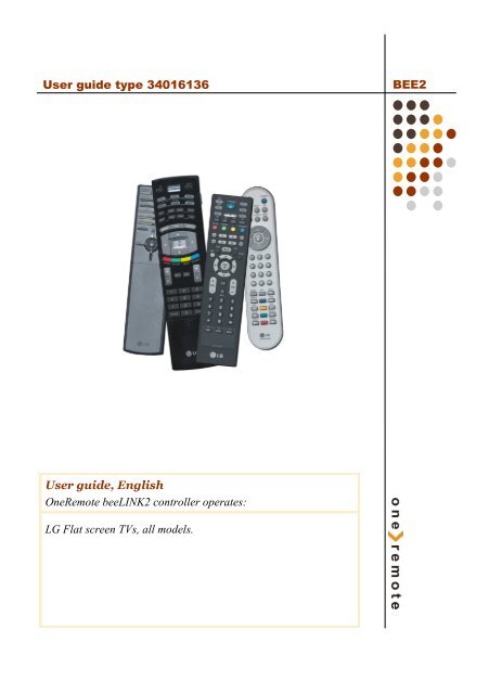
<strong>User</strong> <strong>guide</strong> type 34016136 BEE2<br />
<strong>User</strong> <strong>guide</strong>, <strong>English</strong><br />
<strong>OneRemote</strong> <strong>beeLINK2</strong> <strong>controller</strong> <strong>operates</strong>:<br />
<strong>LG</strong> Flat screen TVs, all models.
Beo4/ Beo5 Translation table.<br />
Daily operations Playback operations<br />
tw Power<br />
OO OK/ enter<br />
W*1 *2 P+<br />
R*1 *2 P-<br />
Q*1 Guide<br />
E*1 Return<br />
m Menu<br />
e Exit<br />
n TEXT<br />
o1 FAV<br />
o3 info<br />
*1<br />
As the direct function of the coloured function<br />
buttons has been assigned to other functions,<br />
these have to be preceded with a o to<br />
retrieve the actual coloured function.<br />
*2<br />
The up/ down arrow operation can be exchanged<br />
with the blue/ yellow buttons. See page.<br />
oQ Green function<br />
oW Yellow function<br />
oE Red function<br />
oR Blue function<br />
2<br />
o Play press 1 sec.<br />
qq Stop<br />
oq Pause<br />
oAS Rew/ FF<br />
Other operations<br />
o 5 List<br />
o8 Simplink<br />
oe Input<br />
Special/ alternative operations<br />
o 0 Play<br />
o 4 Netcast<br />
o 6 AV-mode<br />
o 7 Q-view<br />
om Q-menu<br />
o9 Power<br />
o2 TV/Radio<br />
q1 Ratio
Congratulations<br />
The <strong>beeLINK2</strong> <strong>controller</strong> from www.oneremote.dk can fully<br />
operate your TV using your Bang & Olufsen remote control<br />
terminal, via a beeLINK system bus.<br />
Beo4 or Beo5 remote controls can be used. Beolink 1000 can<br />
be used with reduced functionality. This <strong>guide</strong> explains how.<br />
This <strong>beeLINK2</strong> <strong>controller</strong> is ready for use, plug & play. See<br />
the opposite page regarding daily operation.<br />
Some operations can be altered, to improve interaction with<br />
other <strong>controller</strong>s or to your convenience. Refer to the installation<br />
section further on, if changes are needed.<br />
3
List of Contents<br />
Beo4/ Beo5 Translation table ........................ page 2<br />
beeLINK basics .............................................. page 5<br />
<strong>beeLINK2</strong> installation .................................... page 6<br />
<strong>beeLINK2</strong> connections .................................. page 8<br />
Operation with <strong>OneRemote</strong> - <strong>OneRemote</strong> environment page 9<br />
Beolink 1000 .................................................. page 10<br />
Option programming ...................................... page 11<br />
Programme zapping option ............................ page 11<br />
Menu button option ........................................ page 11<br />
Power off option ............................................ page 12<br />
<strong>beeLINK2</strong> active option ................................. page 13<br />
4
eeLINK basics<br />
The IR data emitted from a Bang & Olufsen remote control, is captured with a IRreceiver.<br />
If there is already one IR-receiver in the room, this can also be used to feed<br />
the BeeLINK bus. There is no need for two IR receivers in the same room.<br />
Data received by the IR-receiver is fed to a <strong>OneRemote</strong> Link Amplifier with built-in<br />
power supply and 5 outputs for beeLINK devices.<br />
If there is more than 5 beeLINK devices in the setup, splitters can be added.<br />
The BeeLINK bus distributes the IR-data, received with the attached IR-receiver from<br />
a Beolink 1000, Beo4 or Beo5 to any number of beeLINK <strong>controller</strong>s. It also supplies<br />
the attached <strong>controller</strong>s with power.<br />
The cable used between the link amplifier and the <strong>controller</strong>s is simple CAT5 type cable<br />
with RJ45 plugs. This type of cable is inexpensive and a standard cable that any<br />
installer are familiar with. Also it is well suited for data transmission. Finally many<br />
modern house installations use the same connectors, making installation even easier.<br />
Note !<br />
A BeeLINK bus must ONLY be connected to other beeLINK components.<br />
If connected to LAN or other systems, there is a great risk to damage these systems.<br />
5
The BeeLINK bus is a parallel bus type. Passive splitters therefore can be used, to<br />
make a network of any shape. If many <strong>controller</strong>s or very long cables are used, it might<br />
be necessary to add more power supplies.<br />
Using this parallel structure each beeLINK <strong>controller</strong> receives the IR-data simultaneously.<br />
Every <strong>controller</strong> has its own microcomputer, living its own life.<br />
Although some of the <strong>controller</strong>s can ‘talk’ to each other, most <strong>controller</strong>s operate fully<br />
on their own.<br />
<strong>beeLINK2</strong> installation<br />
The <strong>beeLINK2</strong> <strong>controller</strong> gets its power supply and control data, via the CAT5 cable<br />
from a beeLINK amplifier. The beeBus.<br />
Once connected to the beeBUS the <strong>beeLINK2</strong> <strong>controller</strong> only needs an IR-emitter to<br />
operate the device it has been designed for. The IR-emitter emits the same IR data as<br />
the device’s own remote control.<br />
Emitted IR data is in fact only light at a frequency just out of the spectrum that the human eye is able to see.<br />
It emits short flashes of light, a bit like when sending Morse codes using a flashlight.<br />
The emitter must be stuck on the device, nearby the Devices IR-receiver. It must be<br />
placed so the IR receiver in the device is able to see the emitted light from the IRemitter.<br />
The <strong>beeLINK2</strong> <strong>controller</strong> can be placed by the device or<br />
in another room. IR emitters are available in lengths of 1,<br />
5 and 10 meters. Additional extension cords can be used.<br />
An IR-emitter can be extended to more than 50 meters.<br />
The IR-emitter can be placed inside the device, if you<br />
want to avoid having it on the outside, as long as the IRreceiver<br />
is able to see the light from the emitter. This<br />
requires that the device is opened and the emitter is placed inside.<br />
A beeBUS CAT5 cable may exceed more than 75 meters without additional amplifiers.<br />
6
eeLINK2 connections.<br />
The IR/ sense socket is output for the IR-emitter that sends IR to the device to be operated.<br />
In some cases this socket is also used for sensing purposes. Sometimes the Bee-<br />
LINK2 <strong>controller</strong> needs to know if the device is powered up or not.<br />
In some cases this socket is used for other serial communications like RS-232 instead<br />
of IR control.<br />
Prog switch is a push button that must be activated to initiate a programming sequence,<br />
as described in the option programming chapters.<br />
Do not use socket is for firmware updating of the <strong>controller</strong>, and connection to special<br />
adapters. If used for anything else, the <strong>controller</strong> will be damaged.<br />
LED indicates different operating states:<br />
Red-green flash: No data has been received since power has been applied<br />
Red flash: The <strong>controller</strong> is in option programming mode.<br />
Red: The <strong>controller</strong> is active.<br />
Green: The <strong>controller</strong> is inactive.<br />
Short off: When the <strong>controller</strong> sends data, the LED turns off 1 sec.<br />
7
Operating with <strong>OneRemote</strong> - <strong>OneRemote</strong> environment.<br />
To be able to operate the device optimal with the Beo4 the user has to be familiar with<br />
operations with the original remote control as described in the device’s user manual.<br />
The beo4 remote control is not equipped with as many keys as most other brands are<br />
using. We have designed a ‘layout’ that works logically, even when shifting between<br />
different <strong>OneRemote</strong> operated devices. To get a common layout for many devices, we<br />
therefore needed to redefine a few of the beo4 buttons to other functions:<br />
Coloured function buttons.<br />
To make room for easy access to more important functions, we have moved the coloured<br />
buttons, to a lower layer. To send a ‘color’ command from the device’s original<br />
RCU, a O must be pressed before the coloured button.<br />
This way we are able to assign other functions to the coloured buttons in direct mode.<br />
In a <strong>OneRemote</strong> environment the coloured buttons are assigned to these operations:<br />
Q<br />
E<br />
W<br />
R<br />
Guide, EPG or similar.<br />
Back, Backup, Return or similar.<br />
Programme zapping. P+/ P- ,<br />
Channel up/ down or CH+/ CH-.<br />
Programme stepping, up/ down manoeuvring in menus.<br />
Most set top boxes or TV’s has 4 arrow buttons for moving up, down, left and right in<br />
on screen menus. In addition they have separate programme stepping buttons for zapping<br />
through programmes. B&O remote controls does not have separate buttons for<br />
programme zapping. We therefore have chosen the blue and the yellow buttons to function<br />
as programme stepping buttons, in direct mode. The four up, down, left and right<br />
buttons have been assigned for manoeuvring in on screen menus, in our basic setup. It<br />
is possible to use the up and down arrow for programme stepping, refer to the option<br />
section, page 6.<br />
Go or Stop shifted operation.<br />
Some of the buttons has 2 or three functions. To get to these they have to be preceded<br />
with O or q. The buttons that has been assigned secondary functions on this<br />
<strong>controller</strong> can be seen in the operating table on page 2.<br />
8
Beolink 1000 and Beo4/ Beo5.<br />
Beolink 1000 and other early Bang & Olufsen remote controls are not equipped with<br />
the coloured function buttons that have been added to Beo4 and Beo5. Some operations<br />
therefore might be less logical or in some cases not available, when using older<br />
remote controls in a beeLINK setup.<br />
Some buttons on the Beolink 1000 remote controls, do actually send the same commands<br />
as differently named buttons on a Beo4/ Beo5. Other buttons simply has been<br />
renamed, but still sends the same commands.<br />
Beolink 1000 Compares to Beo4/ Beo5<br />
------------------- --------------------------------<br />
hZ Q<br />
hX W<br />
hC R<br />
hV E<br />
o P<br />
v T<br />
h v VTAPE2 /VMEM2 /DVD2<br />
s f<br />
h s d / CDV<br />
h t a<br />
y b<br />
h y AMEM2<br />
For compatibility with older remote controls, a typical <strong>OneRemote</strong> layout uses the following<br />
buttons:<br />
Beolink 1000 Typical BeeLINK use<br />
---------------- -----------------------------------------<br />
g Back, Backup e.t.c.<br />
p g EPG, Guide e.t.c.<br />
x EXIT.<br />
p5 Menu.<br />
p9 Manual power.<br />
9
eeLINK2 TV-source option<br />
The BeeLINK active option sets which source button on the remote control, that makes<br />
the BeeLINK2 go active and turns on the TV, as described in the previous chapter.<br />
The BeeLINK source option combines other source buttons on the remote control, with<br />
the input sockets on the TV. The source option can force the TV to open a specific input,<br />
when an AV source is selected.<br />
<strong>LG</strong> TVs can have up to 9 selectable sources, as shown in this table:<br />
0 No new source 1: AV1 2: AV2 3: AV3<br />
4: AV4 5: AV5 6: RGB-PC 7: RGB-Multimedia<br />
8: Component 9: DVI/ HDMI<br />
Source buttons on beo4, like s, T, f,c,y can be programmed to<br />
select one of these inputs. Here are some programming examples:<br />
An option programming sequence is started by pressing the little red switch on the Bee-<br />
LINK2 <strong>controller</strong>, until its LED starts flashing. Then the 3 code option must be entered<br />
with the B&O remote control. Here some examples:<br />
Beo4 Source Volume Action<br />
T1 0> T selects HDMI 1 on the TV. No volume regulation on TV<br />
T2 0> T selects HDMI 2 on the TV. No volume regulation on TV<br />
T1 1> T selects HDMI 1 on the TV. Volume regulation on TV<br />
d2 0> d selects HDMI 2 on the TV. No volume regulation on TV<br />
d9 0> d selects Component on the TV. No volume regulation on TV<br />
c 1 0> c selects Input1 on the TV. No volume regulation on TV<br />
10
eeLINK2 active option.<br />
As all <strong>controller</strong>s on the beeLINK bus are receiving all the IR-data simultaneously,<br />
every <strong>controller</strong> must know when to go active and when to go inactive.<br />
Sometimes two or more <strong>controller</strong>s are active at the same time. A <strong>beeLINK2</strong> <strong>controller</strong><br />
is used to operate a TV, a satellite receiver, a DVD-player, a projector or similar devices.<br />
Each <strong>controller</strong> is specifically made for one device. Many devices can be operated this<br />
way. This is useful when you have more than one device of the same type or simply<br />
run out of source buttons.<br />
When the <strong>beeLINK2</strong> <strong>controller</strong> goes active, its LED will turn red to indicate this. When<br />
another source is selected, the <strong>controller</strong> will go inactive and the LED turn green.<br />
As a <strong>controller</strong> goes active, it will usually turn on the device, if it is not already turned<br />
on.<br />
If the HDMI switch in the example is a beeLINK operated type,<br />
it will automatically switch to the last chosen source.<br />
11<br />
Setup with 3 receivers and a PS3<br />
playstation, attached to both a TV<br />
and a projector.<br />
An example of operation could be:<br />
t1 Operate projector<br />
t2 Operate TV<br />
f1 Operate DVB-S<br />
f2 Operate DVB-T<br />
T Operate DVB-C<br />
f Operate PS3
Made in Denmark by www.oneremote.dk<br />
34016136u1uk