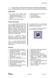
SERIES 56 0.5" Diameter, 200mA, .355" Behind Panel FEATURES Requires Minimum Distance Behind the Panel Adjustable Stop Types Provide Prototypes Immediately Industrial Quality, Economically Priced RoHS Compliant DIMENSIONS In inches (and millimeters) PC Mount Style .500 Ø ± .015 (12,70 ± 0,25) Solder Lug Style .500 Ø ± .015 (12,70 ± 0,38) .094 ± .010 (2,39 ± 0,25) ANGLE OF ANGLE THROW A 30° 105° 36° 108° ANGLE OF ANGLE THROW A 30° 105° 36° 108° .203 ± .003 (5,16 ± 0,08) ACROSS BUSHING FLATS A .094 ± .010 (2,39 ± 0,25) .203 ± .003 (5,16 ± 0,08) ACROSS BUSHING FLATS A POS. 1 POS. 1 .375 ± .015 (9,53 ± 0,38) .250 ± .015 (6,35 ± 0,38) .375 ± .015 (9,53 ± 0,38) .250 ± .015 (6,35 ± 0,38) Ø .125 ± .002 (3,18 ± 0,06) Ø .125 ± .002 (3,18 ± 0,06) .250 ± .015 (6,35 ± 0,38) .250 ± .015 (6,35 ± 0,38) Single Deck <strong>Rotary</strong> <strong>Switches</strong> FOR REAR VIEWS, SEE FOLLOWING PAGE. FOR REAR VIEWS, SEE FOLLOWING PAGE. SOLDER LUG COMMON Grayhill, Inc. • 561 Hillgrove Avenue • LaGrange, Illinois 60525-5997 • USA • Phone: 708-354-1040 • Fax: 708-354-2820 • www.grayhill.com GRAYHILL 2 1 10 9 .377 ± .020 (9,58 ± 0,51) GRAYHILL 2 1 10 9 1/4-28 UNEF-2A THREAD Grayhill part number and date code marked on label. Customer part number marked on request. 1/4-28 UNF-2A THREAD Grayhill part number and date code marked on label. Customer part number marked on request. .110 ± .015 (2,79 ± 0,38) .480 ± .020 (12,19 ± 0,51) .125 ± .015 (3,18 ± 0,38) .110 ± .015 (2,79 ± 0,38) .110 ± .015 (2,79 ± 0,38) PC TERMINAL DETAIL .016 ± .004 SQ. (0,4 ± 0,10) PC COMMON Ø .025 ± .002 (0,64 ± 0,05) SOLDER LUG TERMINAL DETAIL .063 ± .005 (1,60 ± 0,13) .020 ± .004 (0,51 ± 0,10) .125 ± .015 (3,18 ± 0,38) .016 ± .004 (0,4 ± 0,10) .046 ± .004 (1,2 ± 0,10) .016 ± .004 (0,41 ± 0,10) .046 ± .004 (1,17 ± 0,10) Ø .062 ± .002 (1,58 ± 0,51) <strong>Rotary</strong> 11 <strong>Rotary</strong> <strong>Switches</strong>
<strong>Rotary</strong> <strong>Switches</strong> Single Deck <strong>Rotary</strong> <strong>Switches</strong> CIRCUIT DIAGRAMS AND REAR VIEWS: PC Mountable AND Solder Lug Terminals 15° POS. 1 30° TYP. 18° POS. 1 36° TYP. COMMON LOCATION FOR 1 POLE SWITCH Rear View Circuit as Viewed From Shaft End .366 ± .015 (9,30 ± 0,38) DIA. CIRCLE OF CENTERS COMMON LOCATION FOR 1 POLE SWITCH .190 ± .015 (4,83 ± 0,38) DIA. CIRCLE OF CENTERS (PC MOUNT AND SOLDER LUG) COMMON LOCATION FOR 2 POLE SWITCH .340 ± .015 (8,64 ± 0,38) DIA. CIRCLE OF CENTERS DIMENSION A DIA. CIRCLE OF CENTERS COMMON LOCATION FOR 2 POLE SWITCH SPECIFICATIONS Electrical Ratings Chart shown for non-shorting (break before make) contacts, resistive load. CURRENT - MILLIAMPS 300 200 100 0 0 10 20 30 CYCLES x 1000 115 Vac 0r 30 Vdc One cycle is 360° rotation clockwise and 360° return. The data for the curve was measured at sea level, 25°C and 68% relative humidity with the life limiting criteria which follows. Contact Resistance: 100 milliohms maximum, (15 milliohms initially). Insulation Resistance: 10,000 Mohms minimum between mutually insulated parts (50,000 Mohms initially). Voltage Breakdown: 600 Vac minimum between mutually insulated parts at standard atmospheric pressure. Life Expectancy: As determined from the loadlife curve for the current to be switched. Contact GRAYHILL for more information if any of the following is true: the life limiting criteria are more <strong>Rotary</strong> 12 15° POS. 1 30° TYP. PC Mount Solder Lug Dimension Terminals Terminals A .184 ± .015 .126 ± .015 (4,67 ± 0,38) (3,20 ± 0,38) .366 ± .015 (9,30 ± 0,38) DIA. CIRCLE OF CENTERS .190 ± .015 (4,83 ± 0,38) DIA. CIRCLE OF CENTERS (PC MOUNT AND SOLDER LUG) critical than those listed; longer operation is required; a larger make and break current is required; the operating environment includes elevated temperatures or reduced pressures. Contact Carry Rating: Switch will carry 6 amperes continuously with a maximum contact temperature rise of 20°C. Additional Characteristics Contact Type and Forces: Shorting or nonshorting wiping contacts with over 25 grams of contact force. Shaft Flat Orientation: Flat opposite contacting position of pole number one (see circuit diagrams). Terminals: <strong>Switches</strong> have the full circle of terminals, regardless of number of active positions. Stop Strength: 7.5 lb-in. minimum Rotational Torque: 3.5 to 9 oz-in. (21-53 mNm), depending on the number of poles. Bushing Mounting: Required for switches with stops, and recommended for switches without stops. Meets MIL-S-3786 for: High and medium shock; Vibration (10 to 2,000 Hz); Thermal shock (-65° to 85 ° C); Salt spray; Explosion; Stop strength (7.5 in-lbs. minimum (.85 N-m); Terminal strength; Sealed styles withstand water pressure of 15 PSI minimum (103 KPa) without leakage. TWO POLES ONE POLE 6 1 5 2 4 3 ONE POLE FOUR POLES TWO POLES 30° Angle of Throw 36° Angle of Throw Grayhill, Inc. • 561 Hillgrove Avenue • LaGrange, Illinois 60525-5997 • USA • Phone: 708-354-1040 • Fax: 708-354-2820 • www.grayhill.com 7 6 6 5 8 5 7 4 9 10 11 C2 12 C1 1 2 4 3 8 3 9 10 1 2 7 8 9 10 11 12 9 10 8 11 7 C3 C4 12 6 C2 C1 1 5 4 3 2 6 5 7 4 C1 8 3 C2 9 10 1 2 Materials and Finishes Housing: Zinc die cast, tin zinc plated Mounting Nut: Brass, tin zinc plated Lockwasher: Spring steel, zinc plated Panel Seal: Silicone rubber Shaft and Stop Arm: Zinc die cast Retaining Ring: 302 Stainless steel, passivated Shaft Seal: Silicone rubber Stop Pins: 303 Stainless steel, passivated Detent Rotor: Molded thermoplastic Detent Spring: Tinned music wire Detent Balls: Steel, nickel-plated Contact Spring: Stainless steel, passivated Rotor Contact: Brass, silver over nickel plate Common Ring: Brass, gold over silver over nickel plate Terminals: Brass, gold over silver over nickel plate Switch Base: Molded thermoset plastic Mounting Hardware: One mounting nut .089" thick by .375" across flats and one internal tooth lockwasher are supplied with the switch.