MAX3738 DS.C
MAX3738 DS.C
MAX3738 DS.C

You also want an ePaper? Increase the reach of your titles
YUMPU automatically turns print PDFs into web optimized ePapers that Google loves.
<strong>MAX3738</strong><br />
1Gbps 2.7Gbps SFF/SFP<br />
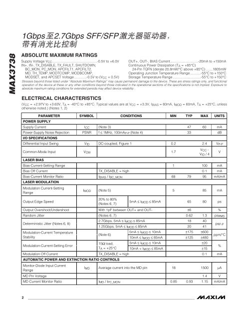
ABSOLUTE MAXIMUM RATINGS<br />
Supply Voltage VCC...............................................-0.5V to +6.0V<br />
IN+, IN-, TX_DISABLE, TX_FAULT, SHUTDOWN,<br />
BC_MON, PC_MON, APCFILT1, APCFILT2,<br />
MD, TH_TEMP, MODTCOMP, MODBCOMP,<br />
MO<strong>DS</strong>ET, and APCSET Voltage.............-0.5V to (VCC + 0.5V)<br />
Stresses beyond those listed under “Absolute Maximum Ratings” may cause permanent damage to the device. These are stress ratings only, and functional<br />
operation of the device at these or any other conditions beyond those indicated in the operational sections of the specifications is not implied. Exposure to<br />
absolute maximum rating conditions for extended periods may affect device reliability.<br />
ELECTRICAL CHARACTERISTICS<br />
OUT+, OUT-, BIAS Current.............................-20mA to +150mA<br />
Continuous Power Dissipation (TA = +85°C)<br />
24-Pin TQFN (derate 20.8mW/°C above +85°C) .......1805mW<br />
Operating Junction Temperature Range...........-55°C to +150°C<br />
Storage Temperature Range .............................-55°C to +150°C<br />
(VCC = +2.97V to +3.63V, TA = -40°C to +85°C. Typical values are at VCC = +3.3V, IBIAS = 60mA, IMOD = 60mA, TA = +25°C, unless<br />
otherwise noted.) (Notes 1, 2)<br />
POWER SUPPLY<br />
PARAMETER SYMBOL CONDITIONS MIN TYP MAX UNITS<br />
Supply Current ICC (Note 3) 47 60 mA<br />
Power-Supply Noise Rejection PSNR f ≤ 1MHz, 100mAP-P (Note 4) 33 dB<br />
I/O SPECIFICATIONS<br />
Differential Input Swing VID DC-coupled, Figure 1 0.2 2.4 VP-P<br />
Common-Mode Input VCM 1.7<br />
LASER BIAS<br />
2 _______________________________________________________________________________________<br />
VCC -<br />
VID / 4<br />
Bias-Current-Setting Range 1 100 mA<br />
Bias Off Current TX_DISABLE = high 0.1 mA<br />
Bias-Current Monitor Ratio IBIAS / IBC_MON 68 79 95 mA/mA<br />
LASER MODULATION<br />
Modulation Current-Setting<br />
Range<br />
Output Edge Speed<br />
IMOD (Note 5) 5 85 mA<br />
20% to 80%<br />
(Notes 6, 7)<br />
5mA ≤ IMOD ≤ 85mA 65 80 ps<br />
Output Overshoot/Undershoot With 1pF between OUT+ and OUT- ±6 %<br />
Random Jitter (Notes 6, 7) 0.62 1.3 psRMS<br />
Deterministic Jitter (Notes 6, 8)<br />
Modulation-Current Temperature<br />
Stability<br />
Modulation-Current-Setting Error<br />
2.7Gbps, 5mA ≤ IMOD ≤ 85mA 18 40<br />
1.25Gbps, 5mA ≤ IMOD ≤ 85mA 20 41<br />
(Note 6)<br />
5mA ≤ IMOD ≤ 10mA ±175 ±600<br />
10mA ≤ IMOD ≤ 85mA ±125 ±480<br />
15Ω load, 5mA ≤ IMOD ≤ 10mA ±20<br />
TA = +25°C 10mA < IMOD ≤ 85mA ±15<br />
Modulation Off Current TX_DISABLE = high 0.1 mA<br />
AUTOMATIC POWER AND EXTINCTION RATIO CONTROLS<br />
Monitor-Diode Input Current<br />
Range<br />
V<br />
psP-P<br />
ppm/°C<br />
IMD Average current into the MD pin 18 1500 µA<br />
MD Pin Voltage 1.4 V<br />
MD Current Monitor Ratio IMD / IPC_MON 0.85 0.93 1.15 mA/mA<br />
%