Overview of the NPS Spacecraft Architecture and Technology ...
Overview of the NPS Spacecraft Architecture and Technology ...
Overview of the NPS Spacecraft Architecture and Technology ...

You also want an ePaper? Increase the reach of your titles
YUMPU automatically turns print PDFs into web optimized ePapers that Google loves.
SSC02-I-4<br />
<strong>Overview</strong> <strong>of</strong> <strong>the</strong> <strong>NPS</strong> <strong>Spacecraft</strong> <strong>Architecture</strong> <strong>and</strong> <strong>Technology</strong><br />
Demonstration Satellite, <strong>NPS</strong>AT1<br />
Daniel Sakoda <strong>and</strong> James A. Horning<br />
Naval Postgraduate School<br />
777 Dyer Rd., Bldg. 233<br />
Code (SP/Sd), Rm. 125<br />
Monterey, CA 93943<br />
dsakoda@nps.navy.mil<br />
ph.: (831) 656-3198; fax; (831) 656-2816<br />
Abstract<br />
This paper describes <strong>the</strong> overall design <strong>of</strong> <strong>NPS</strong>AT1, a low-cost, technology demonstration satellite which hosts a<br />
number <strong>of</strong> experiments. The comm<strong>and</strong> <strong>and</strong> data h<strong>and</strong>ling (C&DH) subsystem is built on commercial, desktop PC<br />
architecture, <strong>and</strong> st<strong>and</strong>ards-based specifications. Combining PC hardware <strong>and</strong> a PC/104 interface bus with <strong>the</strong> robust<br />
Linux operating system s<strong>of</strong>tware <strong>of</strong>fers a means <strong>of</strong> addressing <strong>the</strong> uncertainty <strong>and</strong> difficulty <strong>of</strong> managing space systems<br />
s<strong>of</strong>tware. <strong>NPS</strong>AT1 will also demonstrate <strong>the</strong> use <strong>of</strong> nonvolatile ferroelectric RAM which is inherently radiationtolerant.<br />
Lithium-ion polymer batteries are ano<strong>the</strong>r state-<strong>of</strong>-<strong>the</strong>-art technology that will be employed <strong>of</strong>fering high<br />
energy density for space applications. A novel, low-cost, low-power attitude control subsystem providing coarse,<br />
three-axis stabilization will also be implemented using only magnetic torquers as actuators <strong>and</strong> a three-axis magnetometer<br />
for sensor input.<br />
Experiments on-board <strong>NPS</strong>AT1 include two Naval Research Laboratory (NRL) payloads: <strong>the</strong> coherent electromagnetic<br />
radio tomography (CERTO) experiment <strong>and</strong> a Langmuir probe. The CERTO experiment is a radio beacon which,<br />
in concert with ground station receivers, is used to measure total-electron-content (TEC) in <strong>the</strong> ionosphere. The<br />
Langmuir probe will augment CERTO data by providing on-orbit measurements. The o<strong>the</strong>r experiments are <strong>of</strong> <strong>NPS</strong><br />
origin. These include a configurable processor experiment (CPE), a COTS visible wavelength imager (VISIM), <strong>and</strong> a<br />
three-axis micro-electromechanical systems (MEMS)-based rate gyro. <strong>NPS</strong>AT1 is manifested on <strong>the</strong> Department <strong>of</strong><br />
Defense Space Test Program (STP) MLV-05, Delta IV mission, due to launch in January 2006.<br />
Introduction<br />
The Naval Postgraduate School (<strong>NPS</strong>), located in<br />
Monterey, California, is <strong>the</strong> graduate university for <strong>the</strong><br />
Navy, educating <strong>of</strong>ficers from all services, as well as international<br />
<strong>of</strong>ficer students. The Space Systems Academic<br />
Group is <strong>the</strong> focal point for education <strong>and</strong> research efforts<br />
in space at <strong>NPS</strong>. Two space curricula are <strong>of</strong>fered at<br />
<strong>NPS</strong>, Space Systems Engineering <strong>and</strong> Space Systems<br />
Operations. Education <strong>and</strong> research are married in <strong>the</strong><br />
Small Satellite Design Program which uses spacecraft<br />
development as a vehicle for education, exposing <strong>of</strong>ficer<br />
students to <strong>the</strong> full life-cycle development <strong>of</strong> a space system<br />
while exploring <strong>the</strong> capabilities <strong>of</strong> low-cost, small<br />
satellites. <strong>Spacecraft</strong> in <strong>the</strong> <strong>NPS</strong> Small Satellite Design<br />
Program are Class D spacecraft per MIL-HDBK-343 1<br />
,<br />
defined as a higher risk <strong>and</strong> minimum-cost effort.<br />
1<br />
<strong>NPS</strong> is currently developing <strong>NPS</strong>AT1, <strong>the</strong> second small<br />
satellite to be built at <strong>NPS</strong> by <strong>of</strong>ficer students, faculty,<br />
<strong>and</strong> staff. <strong>NPS</strong> launched a small, digital communications<br />
satellite, PANSAT, aboard <strong>the</strong> Discovery Shuttle in Octo-<br />
ber 1998<br />
Daniel Sakoda 16 th Annual AIAA/USU Conference on Small Satellites<br />
2, 3<br />
. As a follow-on project, <strong>NPS</strong>AT1 builds on<br />
lessons learned from PANSAT, addressing ‘bottlenecks’<br />
in <strong>the</strong> development process, <strong>and</strong> provides greater capability<br />
in <strong>the</strong> spacecraft bus to host a number <strong>of</strong> experiments<br />
while demonstrating innovative, low-cost spacecraft<br />
architectural elements for small satellites.<br />
Mission Objectives<br />
The main objective <strong>of</strong> <strong>NPS</strong>AT1 is to enhance <strong>the</strong> education<br />
<strong>of</strong> <strong>of</strong>ficer students at <strong>NPS</strong>. By providing h<strong>and</strong>s-on<br />
experience working on an actual space system, <strong>of</strong>ficer
students are exposed to <strong>the</strong> realities <strong>of</strong> systems engineering<br />
<strong>and</strong> <strong>the</strong> processes inherent in <strong>the</strong> flow from initial<br />
requirements to flight operations. From <strong>the</strong> st<strong>and</strong>point <strong>of</strong><br />
education, <strong>the</strong> spacecraft is a by-product <strong>of</strong> <strong>the</strong> educational<br />
process. The satellite, itself, will provide a test bed<br />
for technology demonstration <strong>of</strong> commercial, <strong>of</strong>f-<strong>the</strong>-shelf<br />
(COTS) components for space applications; <strong>and</strong> will provide<br />
an experiment platform for o<strong>the</strong>r science experiments.<br />
Space Systems Education<br />
<strong>NPS</strong> <strong>of</strong>fers two curricula in space, Space Systems Engineering<br />
<strong>and</strong> Space Systems Operations. The Space Systems<br />
Engineering curriculum is typically a nine-quarter<br />
program resulting in a Master <strong>of</strong> Science in one <strong>of</strong> <strong>the</strong><br />
engineering or science disciplines <strong>of</strong>fered at <strong>NPS</strong>. The<br />
Space Systems Operations curriculum is typically an<br />
eight-quarter program resulting in a Master <strong>of</strong> Science in<br />
Space Systems Operations. Both curricula require a<br />
graduate <strong>the</strong>sis in a space-related topic. The small satellite<br />
design program, specifically <strong>NPS</strong>AT1, <strong>of</strong>fers meaningful<br />
topics not only in spacecraft subsystem designs,<br />
but also in <strong>the</strong> design, development, <strong>and</strong> testing <strong>of</strong> <strong>the</strong><br />
on-board experiments, <strong>and</strong> spacecraft operations.<br />
<strong>NPS</strong>AT1 has been <strong>the</strong> topic <strong>of</strong> a number <strong>of</strong> classroom<br />
design projects, as well. The initial design concept was<br />
<strong>the</strong> topic <strong>of</strong> <strong>the</strong> capstone spacecraft design course for <strong>the</strong><br />
Space Systems Operations class, AA4831, <strong>Spacecraft</strong> Systems<br />
II, which focused on <strong>the</strong> concept <strong>of</strong> operations <strong>and</strong><br />
helped to identify potential issues. The attitude control<br />
subsystem design was given to <strong>the</strong> AA3818, <strong>Spacecraft</strong><br />
Attitude, Dynamics, <strong>and</strong> Control course. The <strong>NPS</strong>AT1<br />
orbit is studied in <strong>the</strong> SS2500, Orbital Mechanics course,<br />
to perform a coverage analysis <strong>of</strong> <strong>the</strong> camera; <strong>and</strong> <strong>the</strong><br />
preliminary <strong>the</strong>rmal analysis is used as a case study in <strong>the</strong><br />
AA3804, <strong>Spacecraft</strong> Thermal Control course. In short,<br />
<strong>NPS</strong>AT1 <strong>of</strong>fers a wealth <strong>of</strong> resources for <strong>the</strong> class room<br />
for underst<strong>and</strong>ing <strong>and</strong> solving real-world spacecraft design<br />
problems.<br />
<strong>Spacecraft</strong> <strong>Technology</strong> Demonstration<br />
The <strong>NPS</strong>AT1 architecture addresses some <strong>of</strong> <strong>the</strong> lessons<br />
learned from PANSAT which are by no means exclusive<br />
to university-built satellites. The s<strong>of</strong>tware part <strong>of</strong> any<br />
space system is arguably <strong>the</strong> least reliable <strong>and</strong> most prone<br />
to cause schedule delays, <strong>and</strong> thus increases <strong>the</strong> cost <strong>of</strong><br />
<strong>the</strong> program. A likely cause for delays <strong>and</strong> unreliability<br />
is <strong>the</strong> uniqueness <strong>of</strong> <strong>the</strong> space flight hardware as a computing<br />
platform. Because <strong>of</strong> this hardware uniqueness,<br />
s<strong>of</strong>tware cannot be reliably tested until hardware becomes<br />
available on which to run <strong>and</strong> debug s<strong>of</strong>tware drivers,<br />
2<br />
SSC02-I-4<br />
routines, <strong>and</strong> control algorithms. The problem becomes<br />
more readily apparent as more autonomy is required <strong>of</strong><br />
<strong>the</strong> spacecraft which in turn dem<strong>and</strong>s a more sophisticated<br />
operating system.<br />
The <strong>NPS</strong>AT1 comm<strong>and</strong> <strong>and</strong> data h<strong>and</strong>ling (C&DH) subsystem<br />
addresses this issue by adhering to st<strong>and</strong>ards which<br />
are widely accepted in industry. This affords a design<br />
based on commercial, <strong>of</strong>f-<strong>the</strong>-shelf (COTS) products. The<br />
goal <strong>of</strong> <strong>the</strong> <strong>NPS</strong>AT1 small satellite is to demonstrate a<br />
COTS-based C&DH subsystem using PC/104-compliant<br />
computer hardware along with a POSIX-compliant operating<br />
system, namely Linux. The PC/104 architecture is<br />
fully compatible with <strong>the</strong> desktop PC in a miniaturized<br />
configuration. The Linux operating system is a robust,<br />
multi-tasking operating system with a rich environment<br />
for <strong>the</strong> s<strong>of</strong>tware developer. Combining <strong>the</strong> PC/104 hardware<br />
with <strong>the</strong> Linux operating system s<strong>of</strong>tware <strong>of</strong>fers <strong>the</strong><br />
means by which s<strong>of</strong>tware development carried out on<br />
desktop PCs is fully compatible with <strong>the</strong> target flight hardware.<br />
At <strong>NPS</strong>, this means <strong>of</strong>ficer students can work on<br />
s<strong>of</strong>tware algorithms without <strong>the</strong> need to code at <strong>the</strong> hardware<br />
level.<br />
<strong>NPS</strong>AT1 will also demonstrate o<strong>the</strong>r currently available<br />
COTS components which are directly applicable to space.<br />
One such example is ferroelectric (FERRO) memory.<br />
FERRO RAM devices are currently available in sufficient<br />
densities to allow for <strong>the</strong>ir use as a replacement <strong>of</strong> conventional,<br />
or RAD-tolerant RAM devices. FERRO RAM<br />
<strong>of</strong>fers <strong>the</strong> inherent property <strong>of</strong> radiation-tolerance <strong>and</strong><br />
<strong>of</strong>fers nonvolatile memory storage. <strong>NPS</strong>AT1 will demonstrate<br />
<strong>the</strong> use <strong>of</strong> FERRO RAM as part <strong>of</strong> <strong>the</strong> spacecraft<br />
electrical power subsystem (EPS).<br />
Ano<strong>the</strong>r example <strong>of</strong> COTS components which would be<br />
advantageous for space applications is lithium-ion (Liion)<br />
rechargeable batteries. Li-ion batteries <strong>of</strong>fer <strong>the</strong> highest<br />
energy density (Watt-hours per kilogram) than any <strong>of</strong><br />
<strong>the</strong> currently used battery technologies, such as nickelcadmium,<br />
nickel-hydrogen, or nickel-metal hydride.<br />
These batteries <strong>of</strong>fer energy densities starting from 120<br />
Watt-hours per kilogram <strong>and</strong> do not exhibit any ‘memory<br />
effect.’ Two types <strong>of</strong> rechargeable Li-ion batteries are<br />
available. <strong>NPS</strong>AT1 is investigating flying a Li-ion polymer<br />
battery which provides a safe battery cell in terms <strong>of</strong><br />
damage due to overcharging, discharging or h<strong>and</strong>ling.<br />
However issues exist with regard to shelf life <strong>and</strong> manufacturing<br />
consistency that need to be resolved before a<br />
final decision is made on <strong>the</strong> spacecraft energy storage<br />
system.<br />
Daniel Sakoda 16 th Annual AIAA/USU Conference on Small Satellites
Experiment Platform<br />
<strong>NPS</strong>AT1 will host a number <strong>of</strong> experiments described in<br />
more detail in this paper. Two experiments will be provided<br />
by <strong>the</strong> Naval Research Laboratory (NRL). These<br />
are <strong>the</strong> coherent electromagnetic radio tomography<br />
(CERTO) experiment (a three-frequency beacon), <strong>and</strong> a<br />
Langmuir probe. Three o<strong>the</strong>r experiments originate from<br />
within <strong>NPS</strong>. These are a configurable processor experiment<br />
(CPE), <strong>and</strong> two COTS-based experiments, a threeaxis<br />
micro-electromechanical systems (MEMS) rate sensor,<br />
<strong>and</strong> a visible wavelength imager (VISIM), basically,<br />
a digital camera. Finally, <strong>NPS</strong>AT1 will also serve as a<br />
flight demonstration <strong>of</strong> advanced, triple-junction solar<br />
cells with a solar cell measurement system (SMS) to individually<br />
measure current versus voltage (I-V curves)<br />
<strong>of</strong> 24 experiment solar cells. The <strong>NPS</strong>AT1 body-mounted<br />
solar cells will also be <strong>of</strong> <strong>the</strong> same type as <strong>the</strong> 24 experiment<br />
cells.<br />
<strong>Spacecraft</strong> Description<br />
<strong>NPS</strong>AT1 is a 81.6 kg [180 lb] satellite manifested on <strong>the</strong><br />
Department <strong>of</strong> Defense (DOD) Space Test Program (STP)<br />
MLV-05 Delta IV mission due to launch in January 2006.<br />
<strong>NPS</strong>AT1 is one <strong>of</strong> five secondary payloads to share <strong>the</strong><br />
Delta IV using <strong>the</strong> evolved expendable launch vehicle<br />
(EELV) secondary payload adapter (ESPA) 4<br />
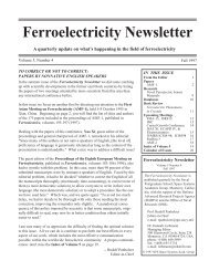
. The overall<br />
configuration is shown in Figure 1, with <strong>the</strong> top, side,<br />
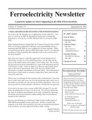
bottom, <strong>and</strong> isometric views shown. Figure 2 shows an<br />
exp<strong>and</strong>ed assembly drawing <strong>of</strong> <strong>the</strong> spacecraft depicting<br />
modules located within <strong>the</strong> spacecraft. The spacecraft is<br />
a 12-sided cylinder with body-mounted solar cells on all<br />
Figure 1. <strong>NPS</strong>AT1 <strong>Spacecraft</strong> Configuration.<br />
3<br />
* Due to trapped protons <strong>and</strong> assuming 300 mil aluminum shielding<br />
SSC02-I-4<br />
<strong>of</strong> <strong>the</strong> cylinder sides. Both ends <strong>of</strong> <strong>the</strong> cylinder have antennas<br />
mounted on <strong>the</strong>m to allow for communications in<br />
<strong>the</strong> event <strong>the</strong> attitude <strong>of</strong> <strong>the</strong> spacecraft is not correctly<br />
nadir-pointing. This configuration assumes <strong>the</strong> risk,<br />
though remote, <strong>of</strong> an ACS failure combined with an attitude<br />
such that <strong>the</strong> cylinder longitudinal axis points at <strong>the</strong><br />
sun in ei<strong>the</strong>r <strong>the</strong> plus or minus sense for an extended period<br />
<strong>of</strong> time resulting in loss <strong>of</strong> solar panel illumination.<br />
Two deployable booms are shown which are <strong>the</strong> CERTO<br />
beacon antenna <strong>and</strong> Langmuir probe boom, respectively.<br />
The spacecraft subsystems include <strong>the</strong> comm<strong>and</strong> <strong>and</strong> data<br />
h<strong>and</strong>ling (C&DH) subsystem, electrical power subsystem<br />
(EPS), attitude control subsystem (ACS), radio frequency<br />
subsystem (RFS), <strong>and</strong> mechanical subsystems which include<br />
<strong>the</strong> spacecraft structure, mechanisms, <strong>and</strong> <strong>the</strong>rmal<br />
design. As a low-cost satellite, few space-rated components<br />
will be used, <strong>and</strong> <strong>the</strong> system will be a ‘single-string’<br />
design. The spacecraft’s circular orbit with altitude <strong>of</strong><br />
560 km <strong>and</strong> 35.4° inclination suggests a relatively radiation–benign<br />
environment. Total dose for <strong>the</strong> spacecraft<br />
electronics is estimated at 200 rad (Si) per year* . However,<br />
radiation tolerant devices will be used for critical<br />
areas, such as in <strong>the</strong> EPS micro-controller <strong>and</strong> memory,<br />
to mitigate <strong>the</strong> risk <strong>of</strong> single event effects (SEE). Within<br />
<strong>the</strong> EPS micro-controller, a watchdog timer will be used<br />
as a check that <strong>the</strong> C&DH processor is operating properly.<br />
Should <strong>the</strong> C&DH not reset <strong>the</strong> watchdog timer<br />
within a set time period, <strong>the</strong> EPS will cycle power to <strong>the</strong><br />
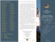
C&DH forcing a reboot. Ano<strong>the</strong>r design feature to be<br />
employed to mitigate SEEs is error-detection-<strong>and</strong>-correction<br />
(EDAC) memory in <strong>the</strong> C&DH. Figure 3 shows<br />
<strong>the</strong> system block diagram <strong>of</strong> <strong>NPS</strong>AT1.<br />
Daniel Sakoda 16 th Annual AIAA/USU Conference on Small Satellites
The spacecraft is intended to operate with a great deal <strong>of</strong><br />
autonomy. Except for <strong>the</strong> RFS, each <strong>of</strong> <strong>the</strong> spacecraft<br />
bus electronics subsystems (C&DH, ACS, <strong>and</strong> EPS) has<br />
its own processor. The EPS <strong>and</strong> ACS, as well as <strong>the</strong> SMS<br />
experiment controller, are very similar in design taking<br />
advantage <strong>of</strong> design modularity. The C&DH performs<br />
<strong>the</strong> bulk <strong>of</strong> <strong>the</strong> scheduling <strong>of</strong> spacecraft <strong>and</strong> experiment<br />
operations. Because <strong>of</strong> limited available power, all experiments<br />
are required to be able to power <strong>of</strong>f in order to<br />
save on electrical power while idle. The C&DH is, itself,<br />
capable <strong>of</strong> undergoing a ‘deep sleep’ mode to save power,<br />
essentially halting its instruction clock. Focusing on good<br />
power management ensures <strong>the</strong> maximum return <strong>of</strong> science<br />
from <strong>the</strong> experiments.<br />
Figure 2. <strong>NPS</strong>AT1 Exp<strong>and</strong>ed View.<br />
4<br />
<strong>NPS</strong>AT1 Startup<br />
SSC02-I-4<br />
Daniel Sakoda 16 th Annual AIAA/USU Conference on Small Satellites<br />
<br />
<strong>NPS</strong>AT1 is designed to be powered <strong>of</strong>f while attached to<br />
<strong>the</strong> launch carrier. This is done as a primary safety inhibit.<br />
Upon separation from <strong>the</strong> ESPA, power is provided<br />
through <strong>the</strong> solar panel bus to <strong>the</strong> EPS. The EPS <strong>the</strong>n<br />
closes a MOSFET switch to put <strong>the</strong> battery on-line <strong>and</strong><br />
powers up <strong>the</strong> C&DH <strong>and</strong> VISIM experiment. Powering<br />
up <strong>the</strong> VISIM is intended to capture pictures <strong>of</strong> <strong>the</strong> launch<br />
vehicle <strong>and</strong> <strong>the</strong> o<strong>the</strong>r secondary payloads. However, <strong>the</strong>re<br />
is some latency in <strong>the</strong> VISIM controller to boot up, <strong>and</strong><br />
tip-<strong>of</strong>f rates may force <strong>the</strong> intended target out <strong>of</strong> view.<br />
The EPS <strong>the</strong>n powers up <strong>the</strong> ACS where initial attitude<br />
acquisition is performed to null <strong>the</strong> rates. <strong>NPS</strong>AT1 <strong>the</strong>n<br />
periodically listens for <strong>the</strong> <strong>NPS</strong> ground station using both<br />
<strong>the</strong> nadir-pointing <strong>and</strong> zenith-pointing antennas. Once
<strong>NPS</strong> contacts <strong>the</strong> spacecraft, orbit ephemeris is uploaded,<br />
<strong>the</strong> real-time clock is synchronized, images from <strong>the</strong><br />
VISIM are downloaded, <strong>and</strong> spacecraft telemetry is downloaded<br />
to determine initial spacecraft operations. At this<br />
time, <strong>the</strong> CERTO <strong>and</strong> Langmuir probe booms may be<br />
deployed by <strong>NPS</strong> comm<strong>and</strong>. With timely orbit ephemeris<br />
onboard, <strong>NPS</strong>AT1 can initiate normal-mode pointing<br />
in <strong>the</strong> ACS, where <strong>the</strong> CERTO <strong>and</strong> Langmuir probe<br />
booms are pointing in <strong>the</strong> plus <strong>and</strong> minus orbit normal,<br />
<strong>and</strong> <strong>the</strong> base <strong>of</strong> <strong>the</strong> spacecraft, where <strong>the</strong> camera is located,<br />
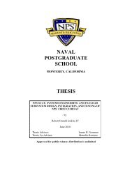
is nadir-pointing. On-orbit checkout <strong>of</strong> <strong>the</strong> <strong>NPS</strong>AT1<br />
spacecraft bus is expected to take two weeks, after which<br />
experiment operations can begin. Figure 4 shows a flow<br />
diagram <strong>of</strong> <strong>the</strong> <strong>NPS</strong>AT1 startup procedure.<br />
Subsystem Descriptions<br />
Comm<strong>and</strong> <strong>and</strong> Data H<strong>and</strong>ling (C&DH) Subsystem<br />
The <strong>NPS</strong>AT1 comm<strong>and</strong> <strong>and</strong> data h<strong>and</strong>ling (C&DH) subsystem<br />
consists <strong>of</strong> several electronic boards which are<br />
attached using <strong>the</strong> PC/104 bus <strong>and</strong> housed within one large<br />
box. These boards are <strong>the</strong> C&DH mo<strong>the</strong>rboard, mass storage,<br />
A/D conversion <strong>and</strong> general purpose input <strong>and</strong> output<br />
(I/O), <strong>the</strong> configurable processor experiment (CPE),<br />
<strong>the</strong> power supply, <strong>the</strong> modem, <strong>and</strong> o<strong>the</strong>r radio frequency<br />
<br />
<br />
<br />
<br />
<br />
<br />
<br />
<br />
5<br />
<br />
<br />
<br />
<br />
<br />
<br />
<br />
<br />
<br />
<br />
<br />
<br />
<br />
<br />
<br />
<br />
<br />
<br />
<br />
<br />
SSC02-I-4<br />
Daniel Sakoda 16 th Annual AIAA/USU Conference on Small Satellites<br />
<br />
<br />
<br />
<br />
<br />
<br />
<br />
<br />
<br />
<br />
<br />
<br />
<br />
<br />
<br />
<br />
<br />
<br />
<br />
Figure 3. <strong>NPS</strong>AT1 System Block Diagram.<br />
<br />
<br />
<br />
<br />
<br />
<br />
<br />
<br />
<br />
<br />
<br />
<br />
<br />
<br />
<br />
<br />
<br />
<br />
<br />
<br />
<br />
<br />
<br />
<br />
<br />
<br />
<br />
<br />
<br />
<br />
<br />
<br />
<br />
<br />
Figure 4. <strong>NPS</strong>AT1 Startup.<br />
<br />
<br />
<br />
<br />
<br />
<br />
<br />
<br />
<br />
<br />
<br />
<br />
<br />
<br />
<br />
<br />
<br />
<br />
<br />
<br />
<br />
<br />
<br />
<br />
<br />
<br />
subsystem (RFS) components. Figure 5 is a block diagram<br />
<strong>of</strong> <strong>the</strong> C&DH mo<strong>the</strong>rboard <strong>and</strong> its interface with<br />
<strong>the</strong> A/D I/O module, <strong>the</strong> CPE, <strong>and</strong> <strong>the</strong> mass storage.<br />
The C&DH mo<strong>the</strong>rboard design is based <strong>of</strong>f <strong>the</strong> PC/104<br />
bus. PC/104 is a compact implementation <strong>of</strong> <strong>the</strong> st<strong>and</strong>ard<br />
PC bus, <strong>the</strong> industry st<strong>and</strong>ard architecture (ISA) bus,<br />
which provides hardware <strong>and</strong> s<strong>of</strong>tware compatibility to<br />
<strong>the</strong> st<strong>and</strong>ard PC. The <strong>NPS</strong>AT1 C&DH incorporates most<br />
<strong>of</strong> <strong>the</strong> PC/104 electrical signals with a board size greater<br />
than <strong>the</strong> typical 3.6" x 3.8". Except for <strong>the</strong> need to con-
serve power <strong>and</strong> for Error Detection <strong>and</strong> Correction<br />
(EDAC) RAM, <strong>the</strong> <strong>NPS</strong>AT1 comm<strong>and</strong> <strong>and</strong> data h<strong>and</strong>ling<br />
(C&DH) subsystem could be implemented using a COTSbased<br />
PC/104 computer.<br />
The C&DH uses a 386 microprocessor running at 33 MHz.<br />
There are 2 Mbytes <strong>of</strong> ROM <strong>and</strong> 16 Mbytes <strong>of</strong> EDAC<br />
static RAM. Five asynchronous serial ports, one port from<br />
<strong>the</strong> 386 <strong>and</strong> four using a multi-port module, provide subsystem<br />
communication <strong>and</strong> a network port for testing <strong>and</strong><br />
integration. A serial communications controller (SCC)<br />
provides two bidirectional channels <strong>of</strong> synchronous serial<br />
in which one channel is used as <strong>the</strong> interface to <strong>the</strong><br />
spacecraft modem. A field programmable gate array<br />
(FPGA) implements <strong>the</strong> PC/104 bus <strong>and</strong> <strong>the</strong> EDAC controller.<br />
The EDAC is one-bit correctable <strong>and</strong> two-bit detectable<br />
<strong>and</strong> based <strong>of</strong>f <strong>of</strong> <strong>the</strong> design used by PANSAT 5 .<br />
The mass storage is a COTS AT Attachment (ATA) interface,<br />
also known as integrated drive electronics (IDE)<br />
solid-state disk with 256 Mbytes <strong>of</strong> memory. This mass<br />
storage device incorporates a small amount <strong>of</strong> bit error<br />
correction. However, only telemetry <strong>and</strong> experimental<br />
data will be stored on this device. Over long periods <strong>of</strong><br />
time bit errors will occur; however, at any time <strong>the</strong> C&DH<br />
can choose to reformat this mass storage unit <strong>the</strong>reby clearing<br />
bit errors. This unit will be repackaged so as to fit<br />
within <strong>the</strong> C&DH housing as a PC/104 stackable board.<br />
Figure 5. C&DH Block Diagram.<br />
6<br />
<br />
<br />
<br />
<br />
<br />
<br />
<br />
SSC02-I-4<br />
The A/D <strong>and</strong> I/O unit is a COTS PC/104 analog I/O module.<br />
The C&DH is responsible for collecting various analog<br />
signals describing temperatures <strong>of</strong> boards <strong>and</strong> parts<br />
within <strong>the</strong> C&DH <strong>and</strong> signal demodulation strength. This<br />
unit also provides digital output which is used to control<br />
<strong>the</strong> local oscillator <strong>of</strong> <strong>the</strong> RF system, <strong>the</strong> GMSK modem,<br />
<strong>and</strong> <strong>the</strong> CERTO <strong>and</strong> Langmuir probe.<br />
The C&DH power supply provides all <strong>of</strong> <strong>the</strong> power conditioning<br />
(3.3V, 5.0V, <strong>and</strong> 12.0V DC) for <strong>the</strong> electronics<br />
within <strong>the</strong> housing, including <strong>the</strong> RF components. The<br />
RFS components within <strong>the</strong> C&DH are isolated from <strong>the</strong><br />
o<strong>the</strong>r electronics for improved electromagnetic compatibility<br />
(EMC).<br />
Linux, a POSIX-compliant operating system, was chosen<br />
as <strong>the</strong> operating system for <strong>the</strong> C&DH for several<br />
reasons. First, it is open-source s<strong>of</strong>tware which is robust<br />
<strong>and</strong> highly configurable. In addition it provides a multitasking<br />
<strong>and</strong> Unix-like environment for s<strong>of</strong>tware development<br />
with which <strong>the</strong> Space Systems Academic Group has<br />
extensive experience. The s<strong>of</strong>tware development tools<br />
are plentiful, free (no cost), <strong>and</strong> powerful.<br />
The C&DH ROM implements a simple BIOS to initialize<br />
<strong>the</strong> 386 microprocessor <strong>and</strong> peripheral hardware to a<br />
known state. The BIOS will <strong>the</strong>n load a compressed version<br />
<strong>of</strong> <strong>the</strong> Linux kernel. Decompression <strong>and</strong> startup <strong>of</strong><br />
<strong>the</strong> kernel is h<strong>and</strong>led by <strong>the</strong> kernel itself. At <strong>the</strong> comple-<br />
Daniel Sakoda 16 th Annual AIAA/USU Conference on Small Satellites
tion <strong>of</strong> <strong>the</strong> kernel startup <strong>the</strong> system will load application<br />
tasks which are also compressed on <strong>the</strong> ROM. A<br />
release <strong>of</strong> <strong>the</strong> Linux 2.4 kernel will be used. Recent developments<br />
for <strong>the</strong> <strong>NPS</strong>AT1 C&DH kernel are using<br />
2.4.14 <strong>and</strong> 2.4.19 with <strong>the</strong> preemptive kernel patch.<br />
Electrical Power Subsystem (EPS)<br />
The electrical power subsystem (EPS) consists <strong>of</strong> triplejunction<br />
solar cells for energy conversion, a lithium-ion<br />
(Li-ion) battery for energy storage, <strong>and</strong> <strong>the</strong> EPS control<br />
electronics which is composed <strong>of</strong> a processor board with<br />
all <strong>the</strong> digital logic <strong>and</strong> an analog/switching board for<br />
power switching <strong>and</strong> telemetry ga<strong>the</strong>ring. The solar cells<br />
are from Spectrolab <strong>and</strong> are part <strong>of</strong> a flight demonstration<br />
which includes <strong>the</strong> solar cell measurement system<br />
(SMS) experiment. The minimum efficiency <strong>of</strong> <strong>the</strong>se<br />
Table 1. Estimated <strong>NPS</strong>AT1 Power Budget.<br />
7<br />
SSC02-I-4<br />
solar cells is 24%. The decision was made early in <strong>the</strong><br />
program to use body-mounted solar arrays, (ra<strong>the</strong>r than<br />
deployable arrays), to reduce <strong>the</strong> risk <strong>of</strong> both inadvertent<br />
deployment <strong>and</strong> failure to deploy or partially deploy. Each<br />
cylinder side is used for solar cells. The zenith-facing<br />
plate is not used because <strong>of</strong> <strong>the</strong> antenna <strong>and</strong> its respective<br />
ground plane. Power budget calculations were performed<br />
using a nominal nadir-pointing attitude with a beta angle<br />
(angle between <strong>the</strong> orbit plane <strong>and</strong> <strong>the</strong> sun vector) <strong>of</strong> 0°.<br />
For <strong>the</strong> 35.4° inclination orbit, <strong>the</strong> beta angle is between<br />
±20° roughly 60% <strong>of</strong> <strong>the</strong> time, with a maximum at about<br />
60°. In order to save on power, all experiments are dutycycled<br />
<strong>and</strong> powered <strong>of</strong>f when not in operation. The power<br />
budget uses average energy available per orbit ra<strong>the</strong>r than<br />
instantaneous power to arrive at scenarios <strong>of</strong> experiment<br />
operation. Table 1 shows <strong>the</strong> power budget for <strong>the</strong> nominal<br />
case where <strong>the</strong> spacecraft is nadir-pointing <strong>and</strong> duty<br />
cycles are as shown.<br />
Subsystem / Component Duty Cycle (%) Avg. Power (W) Avg. Energy/Orbit (W-hr)<br />
EPS Processor Board 50 .75 1.20<br />
Switch Board A/D 50 .03 .05<br />
Switch Board DAC 50 .03 .05<br />
Switches 100 .50 .80<br />
ACS Torque Rods 50 .02 .02<br />
Processor Board 50 .75 1.2<br />
Magnetometer 10 .14 .22<br />
MEMS 1 .02 .04<br />
C&DH 386 Core 50 .80 1.28<br />
EDAC RAM 25 1.02 1.63<br />
SCC 100 .08 0.13<br />
UART 100 .23 0.37<br />
FPGA 100 .25 0.40<br />
Solid State Disk 50 .15 0.24<br />
A/D 100 2.05 3.27<br />
RFS TX/RX 2 .30 .48<br />
LO (& modem) 3 .09 .14<br />
SMS (only operates in sunlight)<br />
Processor Board 5 .12 .12<br />
Switch Board A/D 5 .01 .01<br />
Switch Board DAC 5 .005 .005<br />
CERTO St<strong>and</strong>by 12.5 .43 .69<br />
150/400 MHz mode 20 1.53 2.43<br />
1067 MHz mode 6.6 .34 .54<br />
Langmuir probe 26.5 .42 .68<br />
Configurable Processor Exp. 25 1.00 1.60<br />
VISIM (only operates in sunlight) 8.5 .68 .68<br />
Total Average Energy per Orbit 18.3<br />
Solar Panel Energy (75% eff.) 21.2<br />
Margin (W-hr) 3.0<br />
Daniel Sakoda 16 th Annual AIAA/USU Conference on Small Satellites
The EPS electronics are built around a rad-hard<br />
UTMC80C196KD micro-controller on <strong>the</strong> digital board.<br />
The digital board also hosts a real-time clock, rad-hard<br />
RAM, <strong>the</strong> watchdog timer for <strong>the</strong> C&DH, a serial port to<br />
interface with <strong>the</strong> C&DH, <strong>and</strong> 8 kilobytes <strong>of</strong> ferroelectric<br />
(FERRO) RAM memory. The analog/switching board<br />
hosts all <strong>the</strong> power distribution to <strong>the</strong> o<strong>the</strong>r subsystems to<br />
provide a spacecraft power bus <strong>of</strong> 24V to 40V. Each subsystem<br />
is responsible for regulating <strong>the</strong> power from <strong>the</strong><br />
bus for its own specific requirements. The analog/switching<br />
board is also responsible for taking measurements <strong>of</strong><br />
such things as battery voltages <strong>and</strong> temperatures via 32<br />
analog channels which are multiplexed in to a dual, 12bit<br />
analog-to-digital (A/D) converter. Figure 6 shows <strong>the</strong><br />
block diagram <strong>of</strong> <strong>the</strong> EPS electronics.<br />
<strong>NPS</strong> is currently investigating COTS lithium-ion (Li-ion)<br />
polymer batteries for space applications. Initially, it was<br />
thought that <strong>the</strong> Li-ion polymer batteries would be used<br />
as <strong>the</strong> main energy storage device for <strong>NPS</strong>AT1. However,<br />
due to concerns <strong>of</strong> shelf life, or ‘calendar life’ <strong>of</strong> <strong>the</strong><br />
batteries, manufacturing inconsistencies, <strong>and</strong> <strong>the</strong> rapid<br />
pace <strong>of</strong> commercial Li-ion polymer battery technology,<br />
<strong>the</strong> current baseline is to fly a Li-ion polymer battery as<br />
an experiment to mitigate risk, <strong>and</strong> use a Li-ion battery<br />
(non-polymer) as <strong>the</strong> main spacecraft battery.<br />
<br />
<br />
<br />
<br />
<br />
<br />
<br />
<br />
<br />
<br />
<br />
<br />
Figure 6. EPS Block Diagram.<br />
Attitude Control Subsystem (ACS)<br />
<br />
<br />
<br />
<br />
<br />
<br />
<br />
<br />
<br />
<br />
<br />
<br />
<br />
<br />
<br />
<br />
<br />
<br />
<br />
<br />
<br />
<br />
<br />
<br />
<br />
<br />
<br />
<br />
<br />
<br />
<br />
<br />
<br />
<br />
The <strong>NPS</strong>AT1 attitude control subsystem (ACS) consists<br />
<strong>of</strong> three magnetic torque rods for actuators, a three-axis<br />
magnetometer as <strong>the</strong> sensor, <strong>and</strong> <strong>the</strong> ACS controller. The<br />
ACS design provides a novel, very low-cost solution for<br />
coarse, three-axis attitude control. A detailed discussion<br />
<strong>of</strong> <strong>the</strong> ACS control algorithm design <strong>and</strong> simulation is<br />
given by Leonard 6<br />
. In this paper, <strong>the</strong> hardware design is<br />
8<br />
SSC02-I-4<br />
presented which will be used to implement <strong>the</strong> control<br />
algorithm. In very brief terms, <strong>the</strong> ACS controller uses<br />
onboard orbit information to obtain <strong>the</strong> spacecraft’s location<br />
<strong>and</strong> performs a table lookup to obtain <strong>the</strong> values for<br />
<strong>the</strong> local magnetic field vector at that latitude, longitude,<br />
<strong>and</strong> altitude. Magnetometer measurements are compared<br />
to <strong>the</strong> lookup value <strong>and</strong> <strong>the</strong> control algorithm attempts to<br />
null <strong>the</strong> error between <strong>the</strong> two. Although <strong>the</strong> magnetic<br />
field (B-field) vector gives only one reference vector,<br />
because <strong>the</strong> spacecraft is orbiting <strong>the</strong> Earth <strong>and</strong> <strong>the</strong> ACS<br />
is continually ‘chasing’ <strong>the</strong> B-field vector, three-axis stabilization<br />
can be achieved. Simulation results show that<br />
2° <strong>of</strong> pointing can be achieved.<br />
The ACS electronics is almost identical to <strong>the</strong> EPS controller.<br />
A processor board with a rad-hard<br />
UTMC80C196KD <strong>and</strong> rad-hard RAM will be used to<br />
implement <strong>the</strong> control algorithm. An analog/switching<br />
board is used to drive <strong>the</strong> torque rods, <strong>and</strong> take measurements<br />
from <strong>the</strong> magnetometer, MEMS rate sensor, <strong>and</strong><br />
temperature sensors. The analog/switching board also<br />
provides <strong>the</strong> electrical power for <strong>the</strong> MEMS rate sensor<br />
<strong>and</strong> magnetometer. <strong>Spacecraft</strong> navigation information<br />
(latitude <strong>and</strong> longitude) is required in order to perform<br />
<strong>the</strong> table lookup <strong>of</strong> <strong>the</strong> local B-field vector. Where <strong>the</strong><br />
actual location determination will be performed is yet to<br />
be decided. The issues relate to processing <strong>and</strong> memory<br />
requirements which ultimately are limited by available<br />
power. Ano<strong>the</strong>r option is to perform orbit propagation on<br />
<strong>the</strong> ground <strong>and</strong> send up <strong>the</strong> required information to <strong>the</strong><br />
spacecraft in some form <strong>of</strong> compressed format. Figure 7<br />
shows <strong>the</strong> block diagram <strong>of</strong> <strong>the</strong> ACS electronics.<br />
Figure 7. ACS Block Diagram.<br />
Radio Frequency Subsystem (RFS)<br />
<br />
<br />
<br />
<br />
<br />
<br />
<br />
<br />
<br />
<br />
<br />
<br />
<br />
<br />
The <strong>NPS</strong>AT1 radio frequency subsystem (RFS) is a fullduplex<br />
system with 100 kilobits per second transmission<br />
rate on both <strong>the</strong> uplink <strong>and</strong> downlink channels. As stated<br />
Daniel Sakoda 16 th Annual AIAA/USU Conference on Small Satellites
earlier, <strong>the</strong> antenna system will be able to view in ei<strong>the</strong>r<br />
<strong>the</strong> nadir-pointing direction or <strong>the</strong> zenith-pointing direction<br />
<strong>of</strong> <strong>the</strong> spacecraft in <strong>the</strong> event <strong>the</strong> spacecraft loses<br />
pointing capability. In <strong>the</strong> nominal case where <strong>the</strong> spacecraft<br />
is properly nadir-pointing, only <strong>the</strong> nadir-pointing<br />
antennas will be used for communications. Gaussian,<br />
minimum-shift keying (GMSK) will be used for modulation.<br />
An <strong>of</strong>f-<strong>the</strong>-shelf solution was found for <strong>the</strong> modem.<br />
The frequency conversion electronics between <strong>the</strong> intermediate<br />
frequency (IF) <strong>and</strong> <strong>the</strong> transmit/receive frequencies<br />
is planned to be built in-house.<br />
<strong>NPS</strong>AT1 will operate at 1767.565 MHz in <strong>the</strong> forward,<br />
or uplink channel, with a return link at 2207.3 MHz. The<br />
RFS uses a single-conversion to baseb<strong>and</strong> with 70 MHz<br />
as <strong>the</strong> IF. A maximum bit-error-rate <strong>of</strong> 1x10 -5 was set as a<br />
requirement for <strong>the</strong> system. The link budget shows positive<br />
margins <strong>of</strong> 13.6 dB for <strong>the</strong> forward link <strong>and</strong> 9.8 dB<br />
on <strong>the</strong> return link. Figure 8 shows <strong>the</strong> RFS block diagram<br />
for <strong>the</strong> spacecraft. The modem is physically located<br />
in <strong>the</strong> same housing as <strong>the</strong> C&DH. This is done<br />
because <strong>of</strong> <strong>the</strong> intimate connection between <strong>the</strong> modem<br />
<strong>and</strong> processor board. The modem is manufactured by<br />
SpaceQuest, Ltd., <strong>of</strong> Fairfax, Virginia. The FM Exciter,<br />
responsible for converting <strong>the</strong> GMSK baseb<strong>and</strong> signal to<br />
<strong>the</strong> IF 70 MHz signal, <strong>and</strong> <strong>the</strong> FM Detector, which converts<br />
from <strong>the</strong> IF receive signal to <strong>the</strong> analog baseb<strong>and</strong>,<br />
are <strong>of</strong> <strong>NPS</strong> design.<br />
<br />
<br />
<br />
<br />
<br />
<br />
<br />
<br />
<br />
<br />
Figure 8. <strong>Spacecraft</strong> RFS Block Diagram.<br />
Mechanical<br />
<br />
<br />
<br />
<br />
<br />
<br />
<br />
<br />
<br />
<br />
<br />
<br />
<br />
<br />
<br />
<br />
<br />
<br />
<br />
<br />
<br />
<br />
<br />
<br />
<br />
<br />
<br />
<br />
<br />
The mechanical structure is based on heritage equipment<br />
from a canceled Navy, small satellite program; <strong>and</strong> is<br />
made entirely <strong>of</strong> aluminum. The load-bearing structure<br />
is very robust <strong>and</strong> consists mainly <strong>of</strong> a twelve-sided cylinder<br />
<strong>and</strong> three equipment plates. As a secondary payload,<br />
a robust structure is m<strong>and</strong>atory since <strong>the</strong> launch carrier<br />
is not known at <strong>the</strong> time <strong>of</strong> initial design. Fur<strong>the</strong>r-<br />
9<br />
SSC02-I-4<br />
more, launch opportunities for secondary payloads are not<br />
guaranteed if <strong>the</strong> primary payload is canceled, grows beyond<br />
its initial margin, or is delayed due to funding or<br />
technical problems. Following manifesting on <strong>the</strong> MLV-<br />
05 mission, no attempt was made to optimize <strong>the</strong> <strong>NPS</strong>AT1<br />
structure for weight savings. Although <strong>the</strong> design limit<br />
loads for <strong>the</strong> MLV-05 secondary payloads were not defined,<br />
a conservative estimate <strong>of</strong> 12 g static loads were<br />
applied with a factor <strong>of</strong> safety <strong>of</strong> 1.25 in all directions in<br />
a finite element analysis (FEA), i.e., 15 g in X, Y, <strong>and</strong> Z.<br />
The FEA results were combined by simply adding <strong>the</strong><br />
results for each axis, X, Y, <strong>and</strong> Z, <strong>and</strong> provided margins<br />
<strong>of</strong> safety greater than 5.<br />
An upper section was added to <strong>the</strong> load-bearing structure<br />
to accommodate additional solar panels, <strong>and</strong> is also used<br />
to mount an end plate, <strong>the</strong> zenith-pointing antennas, <strong>and</strong><br />
<strong>the</strong> sun sensor modules required by <strong>the</strong> SMS. This upper<br />
section also allows for approximately two inches <strong>of</strong> area<br />
about <strong>the</strong> cylinder sides for <strong>the</strong> retention device for <strong>the</strong><br />
deployable booms, <strong>and</strong> for h<strong>and</strong>ling points. The actual<br />
requirements for h<strong>and</strong>ling <strong>of</strong> <strong>the</strong> structure are undefined,<br />
however, because <strong>the</strong> integration process for this new<br />
ESPA capability have not been defined. Flexibility becomes<br />
to rule in order to accommodate integration ei<strong>the</strong>r<br />
horizontally or vertically, as well as allowing for correct<br />
angular orientation about <strong>the</strong> separation system, i.e.,<br />
‘clocking.’<br />
<strong>NPS</strong>AT1 mechanisms include <strong>the</strong> microswitches which<br />
are components included with <strong>the</strong> separation system, <strong>the</strong><br />
deployment mechanism <strong>of</strong> <strong>the</strong> deployable booms, <strong>and</strong> <strong>the</strong><br />
retention mechanism which holds <strong>the</strong> booms in <strong>the</strong> stowed<br />
position. The deployment mechanism <strong>of</strong> <strong>the</strong> CERTO antenna<br />
<strong>and</strong> Langmuir probe boom are heritage components<br />
that have flown for approximately 20 years. CERTO, <strong>and</strong><br />
its deployment mechanism, have flown recently on <strong>the</strong><br />
P91-1 ARGOS satellite <strong>and</strong> will launch aboard <strong>the</strong> C/<br />
NOFS satellite. The deployment mechanism is composed<br />
<strong>of</strong> a hinge at <strong>the</strong> base for rotation to <strong>the</strong> stowed position.<br />
The hinge is attached to a short stanchion which is free to<br />
slide inside <strong>the</strong> base <strong>of</strong> <strong>the</strong> boom. The stanchion is connected<br />
to <strong>the</strong> boom via a spring which, when <strong>the</strong> boom is<br />
released, pulls <strong>the</strong> boom <strong>and</strong> joins it with <strong>the</strong> hinged base<br />
via a conical mate, which aligns it normal to <strong>the</strong> base.<br />
The booms will deploy with alignment along <strong>the</strong> +Y axis<br />
<strong>and</strong> -Y axis <strong>of</strong> <strong>the</strong> spacecraft coordinate system, pointing<br />
in <strong>the</strong> plus <strong>and</strong> minus orbit normal directions.<br />
The retention mechanism for <strong>the</strong> deployable booms is <strong>the</strong><br />
least mature aspect <strong>of</strong> <strong>the</strong> spacecraft. Conceptually, a pinpuller<br />
device will be used to hold a lanyard which holds<br />
<strong>the</strong> boom near <strong>the</strong> end, <strong>and</strong> also provides a pre-load on<br />
<strong>the</strong> boom. The boom will have a restraint point such that<br />
Daniel Sakoda 16 th Annual AIAA/USU Conference on Small Satellites
it will look much like a simply supported beam with a<br />
point-load where <strong>the</strong> restraint is located. Issues to be considered<br />
with a deployment mechanism <strong>of</strong> this type fall<br />
under <strong>the</strong> topics <strong>of</strong> inadvertent release, motion-<strong>of</strong>-travel<br />
from beginning to end, electrical malfunction, <strong>and</strong> damage<br />
to <strong>the</strong> nearby equipment, such as <strong>the</strong> solar cells, due<br />
to release event.<br />
Preliminary <strong>the</strong>rmal analyses were performed on <strong>the</strong><br />
<strong>NPS</strong>AT1 spacecraft. However, because <strong>of</strong> <strong>the</strong> changes in<br />
<strong>the</strong> configuration <strong>and</strong> power budget (with <strong>the</strong> addition <strong>of</strong><br />
<strong>the</strong> triple-junction solar cells), a detailed <strong>the</strong>rmal model<br />
remains a near-term goal. Initial results <strong>of</strong> a simple <strong>the</strong>rmal<br />
analysis showed that <strong>the</strong> solar cell temperatures,<br />
which are obviously on <strong>the</strong> spacecraft exterior, range from<br />
-22°C to +30°C. This temperature range is sufficient for<br />
<strong>the</strong> industrial-grade electronics components used in<br />
<strong>NPS</strong>AT1; <strong>and</strong> because <strong>the</strong> electronics are in <strong>the</strong> interior<br />
<strong>of</strong> <strong>the</strong> spacecraft, <strong>the</strong> extreme temperatures should be<br />
bounded well within <strong>the</strong> solar panel temperature range.<br />
The critical components for <strong>the</strong> <strong>the</strong>rmal design are <strong>the</strong><br />
batteries. The lithium-ion polymer batteries need to be<br />
operated within <strong>the</strong> range <strong>of</strong> 0°C <strong>and</strong> +45°C, with optimal<br />
operating temperature at 10°C. The battery design<br />
for <strong>the</strong> lithium-ion polymer batteries accommodates a<br />
heater strip, <strong>and</strong> <strong>the</strong>rmal isolation is planned for <strong>the</strong> batteries<br />
to lower <strong>the</strong> contact conductance between <strong>the</strong> battery<br />
box <strong>and</strong> <strong>the</strong> equipment plate. The detailed <strong>the</strong>rmal<br />
model will provide estimates <strong>of</strong> <strong>the</strong> duty cycling <strong>of</strong> <strong>the</strong><br />
heaters to maintain optimal temperatures.<br />
<strong>NPS</strong>AT1 Experiments<br />
CERTO <strong>and</strong> Langmuir Probe<br />
The CERTO experiment <strong>and</strong> Langmuir probe are two<br />
Naval Research Laboratory (NRL) payloads configured<br />
to operate within <strong>NPS</strong>AT1. The CERTO experiment is a<br />
radio beacon that transmits at three frequencies 150, 400<br />
<strong>and</strong> 1067 MHz. The space-based beacon, in conjunction<br />
with a network <strong>of</strong> ground receivers, will be used to measure<br />
<strong>the</strong> integrated electron density <strong>of</strong> <strong>the</strong> ionosphere in<br />
<strong>the</strong> plane <strong>of</strong> observation. CERTO will also be used to<br />
develop <strong>and</strong> test tomographic algorithms for reconstruction<br />
<strong>of</strong> ionospheric irregularities; to provide a database<br />
for global models <strong>of</strong> <strong>the</strong> ionosphere; to characterize <strong>the</strong><br />
ionosphere for geolocation; <strong>and</strong> to perform scintillation<br />
studies <strong>of</strong> <strong>the</strong> ionosphere. Radio beacons provide measurements<br />
<strong>of</strong> <strong>the</strong> scintillation environment that degrades<br />
military system performance. The electron density characterization<br />
is used to correct for ionospheric refraction<br />
that limits space-based geolocation <strong>of</strong> ground transmitters.<br />
The CERTO beacon may be used in operational systems<br />
for both <strong>of</strong> <strong>the</strong>se uses.<br />
10<br />
SSC02-I-4<br />
<strong>NPS</strong>AT1 will operate <strong>the</strong> CERTO <strong>and</strong> Langmuir Probe in<br />
four modes. The first mode is for checkout <strong>of</strong> <strong>the</strong> electronics,<br />
beacon antenna, <strong>and</strong> <strong>the</strong> probe data collection.<br />
The second mode is <strong>the</strong> mode used in normal day-to-day<br />
operations where <strong>the</strong> objective is to collect total-electroncontent<br />
<strong>and</strong> scintillation data from a chain <strong>of</strong> ground receivers<br />
in <strong>the</strong> USA, South America, <strong>and</strong> India. The 150<br />
<strong>and</strong> 400 MHz frequencies will be on continuously while<br />
over a ground chain. In addition <strong>the</strong> 1067 MHz frequency<br />
will also be used during local times between 18:00 <strong>and</strong><br />
24:00 when within a Latitude <strong>of</strong> ±15º. During normal<br />
operations, <strong>the</strong> Langmuir probe will be enabled collecting<br />
four separate 12-bit A/D channels at samples rates<br />
between 1 <strong>and</strong> 1000 samples per second. Two o<strong>the</strong>r modes<br />
are envisioned which will occur several time a year for a<br />
one to two day period. These special modes are called<br />
CERTO/CITRIS T<strong>and</strong>em modes. Since STPSAT, ano<strong>the</strong>r<br />
spacecraft on <strong>the</strong> MLV-05 mission, will be placed into a<br />
similar orbit with <strong>NPS</strong>AT1 <strong>and</strong> is hosting CITRIS,<strong>the</strong><br />
space-based receiver counterpart to CERTO, conjunctions<br />
with <strong>NPS</strong>AT1 will occur. The objective will be to perform<br />
t<strong>and</strong>em operation for Ionospheric monitoring <strong>of</strong><br />
small scale irregularities. One <strong>of</strong> <strong>the</strong> T<strong>and</strong>em modes will<br />
operate for about eight minutes collecting Langmuir Probe<br />
data. The o<strong>the</strong>r mode will operate for up to two days but<br />
not operate <strong>the</strong> Langmuir probe.<br />
Configurable Processor Experiment (CPE)<br />
The Configurable Processor Experiment (CPE) is a <strong>NPS</strong><br />
module. This experiment consists as a single electronic<br />
circuit board <strong>and</strong> housed within <strong>the</strong> C&DH. It interfaces<br />
with <strong>the</strong> C&DH mo<strong>the</strong>rboard via <strong>the</strong> PC/104 bus for<br />
power <strong>and</strong> digital control <strong>and</strong> data.<br />
The CPE is a low-power design. The design is centered<br />
around a field-programmable gate array (FPGA) which<br />
can be programmed for virtually any type <strong>of</strong> compute<br />
engine for a specific application. The first scenario is to<br />
have <strong>the</strong> board act as a triple-modular, redundant (TMR)<br />
computer, where within <strong>the</strong> FPGA, three core processors<br />
run in-step. Single event effects (SEE) within <strong>the</strong> processing<br />
are detected <strong>and</strong> corrected through voting logic<br />
without <strong>the</strong> need to reboot <strong>the</strong> processor. Because<br />
<strong>NPS</strong>AT1’s orbit is in a relatively radiation-benign orbit,<br />
CPE operations for <strong>the</strong> TMR configuration will focus on<br />
recording SEEs near <strong>the</strong> South Atlantic Anomaly.<br />
The configurable aspect allows in-flight upgrades to <strong>the</strong><br />
processor configuration. The second scenario being considered<br />
is to implement a hardware image compression<br />
engine. This configuration would be capable <strong>of</strong> producing<br />
JPEG representations <strong>of</strong> <strong>the</strong> VISIM data.<br />
Daniel Sakoda 16 th Annual AIAA/USU Conference on Small Satellites
Solar Cell Measurement System (SMS)<br />
As mentioned earlier, <strong>the</strong> solar cells are from Spectrolab<br />
<strong>and</strong> are part <strong>of</strong> a flight demonstration. Twenty-four test<br />
cells will be placed around <strong>the</strong> body <strong>of</strong> <strong>the</strong> spacecraft,<br />
two per each twelve sides, in order to collect data about<br />
<strong>the</strong> performance <strong>of</strong> <strong>the</strong> solar cells. The SMS will perform<br />
current-voltage (IV) curve traces twice per orbit for<br />
each illuminated test cell. Fifty sample points per IV curve<br />
will be collected for each test cell. The data collection<br />
concentrates on three points: <strong>the</strong> open circuit voltage, <strong>the</strong><br />
short circuit current, <strong>and</strong> <strong>the</strong> maximum power point. In<br />
addition temperatures for each panel containing test cells<br />
are collected. <strong>NPS</strong>AT1 has six sun sensor modules to<br />
provide 360° field-<strong>of</strong>-view in azimuth <strong>and</strong> ±64° in elevation.<br />
The modules are <strong>the</strong> model 13-515 double triangle<br />
sun sensor module manufactured by BF Goodrich.<br />
The SMS digital electronics are very similar to <strong>the</strong> ACS<br />
<strong>and</strong> EPS. A processor board with a rad-hard<br />
UTMC80C196KD <strong>and</strong> rad-hard RAM will be used to<br />
implement <strong>the</strong> control algorithm. A control algorithm is<br />
permanently stored in ROM; parameters regarding <strong>the</strong><br />
behavior <strong>of</strong> <strong>the</strong> control can be modified while in orbit. In<br />
addition, a new control algorithm can be uploaded while<br />
in orbit. A solar cell measurement circuit interfaces be-<br />
<br />
<br />
<br />
<br />
<br />
<br />
<br />
<br />
<br />
Ω<br />
<br />
<br />
<br />
<br />
<br />
11<br />
SSC02-I-4<br />
tween <strong>the</strong> test cells <strong>and</strong> <strong>the</strong> microprocessor. This measurement<br />
circuit allows individual control <strong>of</strong> each test cell<br />
to perform <strong>the</strong> IV curve testing <strong>and</strong> provide data to <strong>the</strong><br />
microprocessor. Figure 9 depicts a block diagram <strong>of</strong> <strong>the</strong><br />
SMS.<br />
<br />
<br />
<br />
<br />
<br />
<br />
<br />
<br />
<br />
<br />
<br />
<br />
<br />
<br />
Daniel Sakoda 16 th Annual AIAA/USU Conference on Small Satellites<br />
<br />
<br />
Figure 9. SMS Block Diagram<br />
Visible Wavelength Imager (VISIM)<br />
The Visible Wavelength Imager (VISIM) is a COTS digital<br />
camera operated by a COTS single board computer.<br />
The CCD controller is a PC/104 board. The single-board<br />
computer is a 486 running at 66 MHz supporting <strong>the</strong> PC/<br />
104 bus. The electronics will be modified slightly for<br />
reliability. The CCD <strong>and</strong> controller consume 2.5 W <strong>and</strong><br />
<strong>the</strong> single-board computer ano<strong>the</strong>r 2.5 W. This system<br />
will normally be powered <strong>of</strong>f <strong>and</strong> turned on only for a<br />
small period <strong>of</strong> time when passing over an area <strong>of</strong> interest<br />
to take images <strong>and</strong> process <strong>the</strong> data. A block diagram<br />
<strong>of</strong> this system is shown in Figure 10.<br />
The CCD is an Electrim EDC-1000E. This CCD provides<br />
8-bit color (each) RGB Bayer pattern, a square pixel<br />
<strong>of</strong> 7.4 microns, <strong>and</strong> a resolution <strong>of</strong> 652 horizontal <strong>and</strong><br />
494 vertical. At an exposure time <strong>of</strong> 10 msec, given<br />
<strong>NPS</strong>AT1’s orbit <strong>of</strong> 560 km <strong>and</strong> a focal length <strong>of</strong> 14 mm,<br />
images <strong>of</strong> <strong>the</strong> Earth will have a pixel blur <strong>of</strong> about 0.25
+24 to 40 V DC<br />
+24 V, 0.9 A<br />
Power Conversion<br />
Shutter Controller<br />
SBC<br />
(486/66 MHz)<br />
Shutter<br />
Camera Interface<br />
PC-104<br />
Camera<br />
Camera body<br />
Lens<br />
EDC-1000E Interface<br />
Serial Link<br />
Figure 10. VISIM Block Diagram<br />
C&DH<br />
pixel <strong>and</strong> a field-<strong>of</strong>-view <strong>of</strong> 20° horizontally <strong>and</strong> 30° vertically<br />
or approximately 200 km by 150 km when pointing<br />
exactly nadir. Without increasing pixel blur, exposures<br />
times approaching 1 msec may be possible <strong>and</strong> a<br />
longer focal length lens may yield field-<strong>of</strong>-views <strong>of</strong> about<br />
<strong>of</strong> 6° horizontally <strong>and</strong> 9° vertically or approximately 60<br />
km by 40 km.<br />
The computer runs a version <strong>of</strong> 2.4 <strong>of</strong> <strong>the</strong> Linux operating<br />
system. Currently drivers for version 2.14 are implemented<br />
<strong>and</strong> operating <strong>the</strong> CCD controller. This computer<br />
system accepts comm<strong>and</strong>s from <strong>the</strong> C&DH regarding <strong>the</strong><br />
number <strong>of</strong> images to acquire, <strong>the</strong> time between successive<br />
images, <strong>and</strong> various parameters regarding <strong>the</strong> CCD.<br />
The raw data is lossless-compressed using bzip2. A lossy<br />
representation using JPEG at very high compression is<br />
also generated as a preview <strong>of</strong> <strong>the</strong> image; <strong>the</strong> idea being<br />
that <strong>the</strong>se previews can be downloaded to <strong>the</strong> <strong>NPS</strong> ground<br />
station where it will be decided whe<strong>the</strong>r or not <strong>the</strong> raw<br />
data should also be downloaded in order to save communication<br />
b<strong>and</strong>width. The VISIM computer sends <strong>the</strong><br />
lossless <strong>and</strong> lossy versions <strong>of</strong> <strong>the</strong> raw data back to <strong>the</strong><br />
C&DH for storage <strong>and</strong> for future download to <strong>the</strong> <strong>NPS</strong><br />
ground station. After <strong>the</strong> download <strong>of</strong> data <strong>the</strong> VISIM is<br />
powered <strong>of</strong>f.<br />
Ground Segment<br />
The <strong>NPS</strong>AT1 ground station is located at <strong>the</strong> Naval Postgraduate<br />
School in Monterey, California. This station,<br />
based <strong>of</strong>f <strong>of</strong> <strong>the</strong> PANSAT ground station design, will autonomously<br />
comm<strong>and</strong> <strong>the</strong> spacecraft <strong>and</strong> perform data<br />
collection. A choice to use COTS hardware <strong>and</strong> a foundation<br />
<strong>of</strong> Open Source s<strong>of</strong>tware, was decided in order to<br />
reduce costs <strong>and</strong> development time.<br />
12<br />
Hardware Description<br />
SSC02-I-4<br />
The <strong>NPS</strong>AT1 ground station radio frequency subsystem<br />
consists <strong>of</strong> many <strong>of</strong> <strong>the</strong> same elements as found within<br />
<strong>the</strong> spacecraft. The same SGLS frequencies are used, but<br />
reversed for uplink/downlink, as <strong>the</strong> spacecraft. The antenna<br />
is a 3.3 m reflecting dish with left or right circular<br />
polarization, a single L/S B<strong>and</strong> feed, <strong>and</strong> two-axis position<br />
control. The ground modem interface, Figure 11, is<br />
very similar to its spacecraft counterpart, except for <strong>the</strong><br />
diplexer at <strong>the</strong> antenna <strong>and</strong> reversal <strong>of</strong> <strong>the</strong> frequencies for<br />
uplink <strong>and</strong> downlink.<br />
<br />
<br />
<br />
<br />
<br />
<br />
Daniel Sakoda 16 th Annual AIAA/USU Conference on Small Satellites<br />
<br />
<br />
<br />
<br />
<br />
<br />
<br />
<br />
<br />
<br />
<br />
<br />
<br />
<br />
<br />
<br />
<br />
<br />
<br />
<br />
<br />
Figure 11. Ground Modem Interface<br />
A single COTS PC compatible computer controls <strong>the</strong> entire<br />
system. This includes interfaces to <strong>the</strong> antenna tracking,<br />
<strong>the</strong> ground modem interface, <strong>and</strong> <strong>the</strong> transmit <strong>and</strong><br />
receive local oscillators which are programmed for Doppler<br />
shift. This PC tracks <strong>the</strong> spacecraft using a modified<br />
version <strong>of</strong> SatTrack, which is open source Unix-based<br />
s<strong>of</strong>tware. Telemetry <strong>and</strong> experimental data are collected<br />
on <strong>and</strong> archived from this computer. This ground station<br />
computer is attached to a LAN so as to simplify <strong>the</strong> distribution<br />
<strong>of</strong> spacecraft data <strong>and</strong> <strong>the</strong> scheduling <strong>of</strong> spacecraft<br />
activities. <strong>Spacecraft</strong> ephemeris is updated daily by<br />
<strong>the</strong> ground station.<br />
Ground Site Operations<br />
The Naval Postgraduate School, located at a latitude <strong>of</strong><br />
36.6° N, will have approximately five passes per day with<br />
about six minutes for each pass. This averages to about<br />
34 minutes a day <strong>of</strong> communication (10° above <strong>the</strong> horizon).<br />
At 100 kbit/sec <strong>the</strong> ground station will be able to<br />
download approximately 20 Mbytes <strong>of</strong> spacecraft telemetry<br />
<strong>and</strong> experimental data every day.<br />
Daily operations will be broken into several passes, about<br />
1-1/2 hours apart. A typical day will start with <strong>the</strong> first<br />
pass uploading orbit ephemeris <strong>and</strong> spacecraft time.<br />
Thereafter <strong>the</strong> JPEG previews <strong>of</strong> <strong>the</strong> VISIM pictures will<br />
be downloaded. As time allows, <strong>the</strong> downloading <strong>of</strong> stored
telemetry <strong>and</strong> experimental data will continue. Immediately<br />
after this pass, spacecraft operators (<strong>and</strong>/or s<strong>of</strong>tware)<br />
will select VISIM pictures in which <strong>the</strong> raw data should<br />
be downloaded during <strong>the</strong> next pass. In addition, abnormal<br />
conditions within <strong>the</strong> spacecraft as detected by analyzing<br />
<strong>the</strong> telemetry will cause <strong>the</strong> ground station to notify<br />
<strong>NPS</strong> personnel via email.<br />
The second <strong>and</strong> later passes will continue as follows. The<br />
ground station will continue downloading telemetry,<br />
VISIM raw data (as selected from <strong>the</strong> previews), <strong>and</strong> data<br />
from <strong>the</strong> o<strong>the</strong>r experiments. Upon completion <strong>of</strong> <strong>the</strong><br />
downloading, as time <strong>and</strong> available power on <strong>the</strong> spacecraft<br />
allow, uploading <strong>of</strong> various information to <strong>NPS</strong>AT1<br />
begins. This includes new VISIM targets; new parameters<br />
for CERTO/Langmuir probe, <strong>the</strong> ACS, EPS, SMS,<br />
<strong>and</strong> VISIM; new controller s<strong>of</strong>tware for <strong>the</strong> ACS, EPS,<br />
SMS, <strong>and</strong> VISIM; <strong>and</strong> new or modified applications for<br />
<strong>the</strong> C&DH.<br />
Experimental data from <strong>the</strong> CERTO/Langmuir probe <strong>and</strong><br />
<strong>the</strong> solar cell experiments will be immediately available<br />
to those requiring <strong>the</strong> data via <strong>the</strong> Internet. O<strong>the</strong>r select<br />
data regarding <strong>the</strong> general status <strong>of</strong> <strong>the</strong> spacecraft will<br />
also be published immediately on <strong>the</strong> Internet via a World<br />
Wide Web (WWW) server. As part <strong>of</strong> an educational<br />
outreach, <strong>NPS</strong> will make <strong>the</strong> VISIM pictures available<br />
via <strong>the</strong> WWW. In addition to viewing VISIM pictures,<br />
users will be able to request sites desired for future image<br />
taking.<br />
Conclusions<br />
<strong>NPS</strong>AT1 <strong>of</strong>fers a novel spacecraft architecture which can<br />
be used as a template for <strong>the</strong> small satellite builder. The<br />
innovative design promises a means <strong>of</strong> s<strong>of</strong>tware streamlining<br />
<strong>and</strong> enriching <strong>the</strong> s<strong>of</strong>tware development process<br />
by using widely-available <strong>and</strong> low-cost tools. The spacecraft<br />
will also serve as a platform for science experiments<br />
with military relevance, a validation <strong>of</strong> low-cost technology<br />
for space applications, <strong>and</strong> <strong>of</strong> course, enhancing <strong>the</strong><br />
<strong>NPS</strong> mission <strong>of</strong> education.<br />
References<br />
1 . Design, Construction, <strong>and</strong> Testing Requirements<br />
for One <strong>of</strong> a Kind Space Equipment, DOD-<br />
HDBK-343, Feb. 1986, USAF.<br />
2 . D. Sakoda, R. Phelps, J. Horning, D. Rigmaiden,<br />
<strong>and</strong> J. Damerau, “Naval Postgraduate School<br />
13<br />
SSC02-I-4<br />
PANSAT: Lessons Learned,” Proceedings <strong>of</strong> <strong>the</strong><br />
AIAA Space 2001 Conference <strong>and</strong> Exposition,<br />
Albuquerque, NM, August 28-30, 2001.<br />
3 . D. Sakoda, “<strong>Overview</strong> <strong>of</strong> <strong>the</strong> Naval Postgraduate<br />
School Petite Amateur Navy Satellite<br />
(PANSAT),” Proceedings <strong>of</strong> <strong>the</strong> Thirteenth<br />
Annual AIAA/Utah State University Conference<br />
on Small Satellites, Paper SSC99-I-5, Logan,<br />
Utah, Aug. 1999.<br />
4 . Lt. J.S. Goodwin, S. Weis, L. Berenberg, <strong>and</strong> Dr.<br />
P. Wegner, “Evolved Expendable Launch Vehicle<br />
Secondary Payload Adapter - A New Delivery<br />
System for Small Satellites,” Proceedings <strong>of</strong> <strong>the</strong><br />
Fifteenth Annual AIAA/Utah State University<br />
Conference on Small Satellites, Paper SSC01-X-<br />
6, Logan, Utah, Aug. 2001.<br />
5 . C. R. Oechsel, Implementation <strong>of</strong> Error Detection<br />
<strong>and</strong> Correction (EDAC) in <strong>the</strong> Static<br />
R<strong>and</strong>om Access Memory (SRAM) Aboard Petite<br />
Amateur Navy Satellite (PANSAT), Master <strong>of</strong><br />
Science in Electrical Engineering Thesis, Naval<br />
Postgraduate School, Monterey, California,<br />
March 1995.<br />
6. B. Leonard, “<strong>NPS</strong>AT1 Magnetic Attitude<br />
Control System,” (to be published) Proceedings<br />
<strong>of</strong> <strong>the</strong> Sixteenth Annual AIAA/Utah State<br />
University Conference on Small Satellites,<br />
Paper SSC02-V-7, Logan, Utah, Aug. 2002.<br />
Daniel Sakoda 16 th Annual AIAA/USU Conference on Small Satellites