3Badu Bronze-GB - SPECK-Pumpen
3Badu Bronze-GB - SPECK-Pumpen
3Badu Bronze-GB - SPECK-Pumpen

Create successful ePaper yourself
Turn your PDF publications into a flip-book with our unique Google optimized e-Paper software.
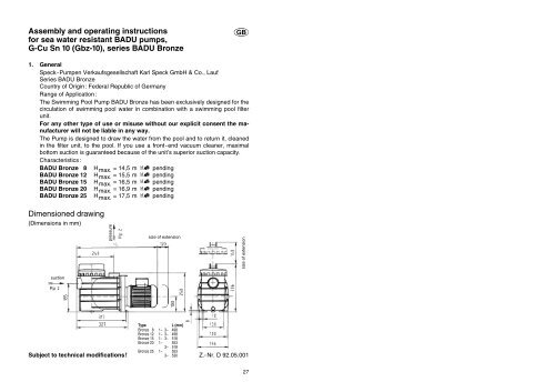
Assembly and operating instructions<br />
for sea water resistant BADU pumps,<br />
G-Cu Sn 10 (Gbz-10), series BADU <strong>Bronze</strong><br />
1. General<br />
Speck-<strong>Pumpen</strong> Verkaufsgesellschaft Karl Speck GmbH & Co., Lauf<br />
Series BADU <strong>Bronze</strong><br />
Country of Origin: Federal Republic of Germany<br />
Range of Application:<br />
The Swimming Pool Pump BADU <strong>Bronze</strong> has been exclusively designed for the<br />
circulation of swimming pool water in combination with a swimming pool filter<br />
unit.<br />
For any other type of use or misuse without our explicit consent the manufacturer<br />
will not be liable in any way.<br />
The Pump is designed to draw the water from the pool and to return it, cleaned<br />
in the filter unit, to the pool. If you use a front-end vacuum cleaner, maximal<br />
bottom suction is guaranteed because of the unit’s superior suction capacity.<br />
Characteristics:<br />
BADU <strong>Bronze</strong> 8 H max. = 14,5 m pending<br />
BADU <strong>Bronze</strong> 12 H max. = 15,5 m pending<br />
BADU <strong>Bronze</strong> 15 H max. = 16,5 m pending<br />
BADU <strong>Bronze</strong> 20 H max. = 16,9 m pending<br />
BADU <strong>Bronze</strong> 25 H max. = 17,5 m pending<br />
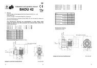
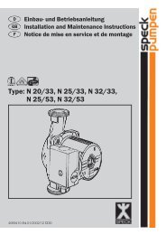
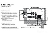
Dimensioned drawing<br />
(Dimensions in mm)<br />
suction<br />
pressure<br />
size of extension<br />
Type L (mm)<br />
<strong>Bronze</strong> 8 1~ 3~ 498<br />
<strong>Bronze</strong> 12 1~ 3~ 498<br />
<strong>Bronze</strong> 15 1~ 3~ 518<br />
<strong>Bronze</strong> 20 1~ 3~ 553<br />
1~ 3~ 518<br />
<strong>Bronze</strong> 25 1~ 3~ 553<br />
Subject to technical modifications! 1~ 3~ 530<br />
Z.-Nr. D 92.05.001<br />
<strong>GB</strong><br />
size of extension<br />
27
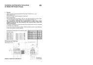
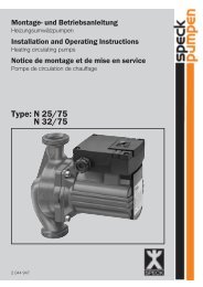
Characteristics<br />
BADU <strong>Bronze</strong>,<br />
applicable for<br />
water of 20°C<br />
KL 92.05.001<br />
Type of motor enclosure IP 54<br />
Class of insulation F<br />
Motor speed approx. 2840<br />
Continuous sound intensity level dB (A) ≤ 70 1)<br />
Max. water temperature (°C) 60<br />
Max. casing pressure (bar) 2,5<br />
28<br />
total dynamic head (H in mm)<br />
For IEC standard voltage according to DIN IEC 38 (eurovoltage). Suitable<br />
for continuous operation at 1~220-240 V and at 3~Y/∆ 380-420 V/220-240 V.<br />
Tolerances according to VDE 0530 part 1 = ^ ± 5%.<br />
*) Inside thread according to DIN 2999 (sealed with Teflon tape only)<br />
1) Measured with a phonemeter in 1 m distance and 1,6 m height<br />
2) pending<br />
Flow rate (Q in m 3/h)<br />
Technical data at 50 Hz <strong>Bronze</strong> 8 <strong>Bronze</strong> 12 <strong>Bronze</strong> 15 <strong>Bronze</strong> 20 <strong>Bronze</strong> 25<br />
2) 2) 2) 2) 2)<br />
inlet/outlet connection (Rp) *) 2 / 2 2 / 2 2 / 2 2 / 2 2 / 2<br />
Recommended inlet/outlet pipe, PVC-pipe, d 50 / 50 50 / 50 63 / 50 63 / 63 63 / 63<br />
Power input P 1 (kW) 1~230 V 0,58 0,65 0,97 1,30 1,70<br />
Power output P 2 (kW) 1~230 V 0,30 1) 0,45 1) 0,65 1) 1,00 1) 1,30 1)<br />
Rated current (A) 1~230 V 2,60 3,20 4,70 5,80 7,40<br />
Power input P 1 (kW) 3~Y/∆ 400/230 V 0,44 0,66 0,90 1,32 1,65<br />
Power output P 2 (kW) 3~Y/∆ 400/230 V 0,30 1) 0,45 1) 0,65 1) 1,00 1) 1,30 1)<br />
Rated current (A) 3~Y/∆ 400/230 V 0,85/1,50 1,10/1,90 1,60/2,80 2,50/4,30 3,00/5,20<br />
Weight (kg) 1~ 25,6 25,6 28,0 30,2 30,2<br />
Weight (kg) 3~ 25,3 25,3 27,7 28,0 31,2<br />
2. Safety<br />
The Operation Manual contains basic instructions which must be obeyed during<br />
mounting, operation and maintenance. Therefore, the Operation Manual should<br />
be carefully read before installation and startup by the person in charge of the<br />
installation as well as by all other technical personnel/operators and should at<br />
all times be available at the installation site.<br />
It is important that not only all general safety measures appearing under the<br />
above heading „Safety” should be adhered to but also all other, specialised<br />
safety instructions appearing under different headings, e.g. when used by<br />
private customers.<br />
2.1 Symbols for Safety Instructions in the Operation Manual<br />
All safety warnings contained in the Operation Manual which, when ignored,<br />
may constitute danger for humans, are marked with general danger symbols.<br />
!<br />
Safety symbol according to DIN 4844 - W 9;<br />
in case of electrical hazards they are specially marked with<br />
Safety symbol according to DIN 4844 - W 8.<br />
For safety warnings which, when ignored, may constitute a hazard for the machine<br />
and its functions, the word<br />
CAUTION<br />
is added.<br />
Symbols directly attached to the machine like e.g.<br />
– arrow denoting the direction of rotation<br />
– symbol for fluid connections<br />
must be heeded and kept legible at all times.<br />
29
2.2 Personnel Qualification and Training<br />
All operation, inspection and installation personnel must be qualified for these<br />
jobs. Scope of responsibility, competency and the supervision of the personnel<br />
must be clearly defined by the operator. If the personnel is not fully qualified,<br />
they must be properly trained and instructed. If necessary and if required, the<br />
manufacturer/deliverer may train customer personnel. Furthermore, the operator<br />
must make sure that the contents of the Operation Manual is fully understood<br />
by the personnel.<br />
2.3 Dangers and Hazards resulting from Non-Compliance with Safety Warnings<br />
Non-compliance with safety warnings may constitute a hazard for persons as<br />
well as for the environment and the machine. Non-compliance with safety warnings<br />
may void any guarantees or claims for damages.<br />
Here are a few examples where non-compliance may entail the following hazards:<br />
– Failure of important functions of the machine/plant<br />
– Failure of manufacturer-recommended servicing and maintenance procedures<br />
– Hazards to human beings through electrical, mechanical or chemical reaction<br />
– Danger to the environment through leakage of hazardous substances<br />
2.4 Safety-orientated operation<br />
Safety warnings contained in this Operation Manual, all existing national rules<br />
and regulations for the prevention of accidents as well as any internal work or<br />
operational safety precautions by the operator must be complied with.<br />
2.5 General Safety Warnings for the User/Operator<br />
If hot or cold machine parts should present a hazard, such parts must be protected<br />
against accidental contact.<br />
Protective devices for moving parts (e.g. couplings) must never be removed<br />
while the machine is in operation.<br />
Leakages (e.g. of the mechanical seal) of hazardous substances (e.g. explosive,<br />
toxic, hot) must be drained off in such a way that any danger to persons<br />
and the environment is prevented. All pertinent rules and regulations must be<br />
obeyed.<br />
Danger through electrical energy must be avoided (for details see safety rules<br />
established by VDE and the local utilities.)<br />
2.6 Safety warnings for Maintenance, Inspection and Installation Work<br />
The operator shall be responsible for all maintenance, inspection and installation<br />
work to be performed by authorised and qualified technical personnel thoroughly<br />
acquainted with the Operation Manual.<br />
Basically, any work on the machine should only be performed when the machine<br />
is shut down. The proper procedure for shutting down the engine described<br />
in the Operation Manual must be adhered to unconditionally.<br />
30<br />
Pumps or aggregates which are used to pump hazardous substances must be<br />
decontaminated.<br />
Immediately after the work is completed, all safety and protective devices must<br />
be reattached or activated, respectively.<br />
Before restarting the machine, all points (!!) contained in the chapter „Initial<br />
startup” should be observed.<br />
2.7 Unauthorised Alterations or Modifications and the Manufacturing of Spare<br />
Parts<br />
Alterations/Modifications or changes in the machine’s design require the prior<br />
consent by the manufacturer. Original spare parts and accessories authorised<br />
by the manufacturer enhance the machine’s safety. Using other spare parts<br />
may void any liability for consequential damages on the part of the manufacturer.<br />
2.8 Unauthorised Operation<br />
The operational safety of the machine can only be guaranteed whenever it is<br />
operated in accordance with Section 1 – General – of the Operation Manual.<br />
The limiting values stated in the data sheets must never be exceeded.<br />
Cited Standards/Norms and other Documentation<br />
DIN 4844 Part 1 Safety marking; Safety symbol W 8<br />
Supplement 13<br />
DIN 4844 Part 1 Safety marking; Safety symbol W 9<br />
Supplement 14<br />
3. Shipping and Intermediate Storage<br />
Prolonged intermediate storage in a high-humidity environment and changing<br />
temperatures should be avoided. Condensation water may affect windings and<br />
metallic parts. This will void the guarantee.<br />
4. Description<br />
BADU <strong>Bronze</strong> pumps have been designed to circulate pool water in combination<br />
with a corresponding filter unit. All parts in contact with the pumped medium<br />
are predominantly made from sea water resistant bronze G-Cu Sn 10<br />
(Gbz-10) and thus feature excellent resistance against the pool water, natural<br />
sea water or the usual chemicals for treatment of the pool water, respectively.<br />
The motor shaft also serves as the pump shaft which carries the impeller. The<br />
shaft is sealed by means of a bellows-type mechanical seal which is attached<br />
to the plastic impeller hub. This guarantees positive electrical separation<br />
between the pool water and the electric motor. Because of the pump’s close<br />
coupled design, a minimum of space is required. The pumps are driven by<br />
three-phase current, or A.C. motors. Integrated in the pump housing is a strainer<br />
basket which keeps coarse impurities from the pump’s interior.<br />
31
5. Installation/Assembly<br />
5.1<br />
CAUTION<br />
5.2<br />
5.3<br />
32<br />
The installation site of the pump must be dry. If the pump is installed in a humid<br />
space, effective ventilation and aeration must be provided for in order to prevent<br />
condensation from forming.<br />
In case of very small installation spaces, the natural cooling of the air may be<br />
so insignificant that, also there, ventilation and aeration is mandatory in order<br />
not to exceed the environmental temperature of 40°C. Enough reserve space<br />
must be provided for to allow removal and replacement of the motor unit in the<br />
direction of the motor fan (120 mm respectively), or of the strainer basket towards<br />
above (min. 140 mm). (See directions in the dimensional drawing).<br />
CAUTION<br />
Mechanical/Hydraulic Aspects:<br />
The pump must be installed level and in a dry place. It may be installed either<br />
below (Gravity feed, max. 5 m), or above the water level (in suction mode). In<br />
that case, the head between water level and pump (geodetic head) may not exceed<br />
3 m. The suction lift may be significantly reduced by flow resistance in the<br />
suction line. (Excessively long or insufficiently dimensioned pipes). Use only<br />
sealing tape for connecting sleeves to pumps! If the suction line is leaky or<br />
the lid has not been screwed on tightly, the pump will prime insufficiently or not<br />
at all. The intake line should be kept as short as possible. This will reduce priming<br />
time which is a function of the air volume inside the intake line. With very<br />
long intake lines, priming will take up to 12 minutes. If possible, the intake line<br />
to the pump should be installed below the water level. Wherever the pump<br />
must be installed above the water level, the installation of a footvalve is recommended.<br />
Thus the intake line cannot drain when the pump is not working. This<br />
keeps priming time short (e.g. after cleaning the strainer basket). Also, the<br />
transparent lid must be attached tightly and securely.<br />
Electrical Installation to be performed by qualified personnel only!<br />
Make sure that the electrical installation is equipped with an earth leakage<br />
switch which permits separation from the power supply by a gap of at least<br />
3 mm for each contact. The pump has been designed in accordance with protection<br />
system I. The environmental temperature must never exceed 40°C. For<br />
!<br />
pumps with three-phase motors a properly adjusted motor cutout switch must<br />
be installed. Please refer to motor nameplate. Failure to do this will void the<br />
guarantee in case of motor failure. Pumps with A.C. motors should be provided<br />
with a winding breaker contact.<br />
Caution! The use of pumps for swimming pools and the restricted area<br />
around them is only permitted if pumps are installed in accordance with<br />
DIN/VDE 0100 Part 702. Please, consult your licensed electrician!<br />
The supply circuit has to be protected with a fault current contactor with a<br />
nominal fault current of I∆N ≤ 30 mA.<br />
From 1 kW single-phase motors (1~) on a power supply of minimally 3 x 1,5<br />
mm 2 H07 RN-F or equivalent must be provided for.<br />
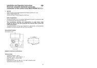
Opening the terminal box cover with BADU <strong>Bronze</strong> 8, 12, 15<br />
6. Initial Startup<br />
6.1<br />
CAUTION<br />
Unscrew the transparent strainer lid anticlockwise (if necessary use the spanner<br />
supplied), slowly fill the pump with clean water until the water level reaches<br />
the inlet connection. Ensure the lid O-ring (412.1) as well as the sealing surface<br />
on the lid is clean. Close the strainer lid (160) clockwise until it is properly<br />
closed. If the lid is not properly closed the pump will not prime correctly or may<br />
not prime at all.<br />
Do not allow the pump to run dry, not even if only to check the direction<br />
of rotation.<br />
6.2<br />
CAUTION<br />
The pump must never be operated without the strainer basket (143) or the<br />
strainer basket handle (otherwise the strainer basket will float upward) in order<br />
to avoid clogging or blocking.<br />
6.3<br />
CAUTION<br />
!<br />
At the initial startup of 3-phase pumps, care must be taken that the motor is<br />
turning in the direction of the arrow (seen from the fan: clockwise). If the direction<br />
of rotation is wrong, immediately call a licensed electrician.<br />
33
6.4<br />
Make sure that the shutoff valves in the inlet and outlet lines are fully open. The<br />
pump must never be operated with closed shutoff valves!<br />
7. Maintenance/Service<br />
The strainer basket must be cleaned at certain intervals. In case of clogged or<br />
full basket, the rate of flow will decrease and will affect the filtration quality.<br />
7.1 Cleaning the strainer basket:<br />
1.Switch off pump.<br />
2.Close all shutoff valves.<br />
3.Remove transparent lid. If necessary use the spanner supplied. Remove<br />
strainer basket, clean it and replace it. Cover O-ring with a film of vaseline.<br />
Close transparent lid again. (See items 6.1 and 6.4). Make sure that the position<br />
of the suction strainer handle is at 90° in relation to the housing.<br />
4.Open shutoff valves.<br />
5.Switch on pump.<br />
7.2<br />
7.3<br />
7.4<br />
34<br />
CAUTION<br />
CAUTION<br />
CAUTION<br />
Whenever the pump is deactivated by means of the motor cutout or overload<br />
switches, the pump should be checked for easy rotation before restarting it.<br />
Turn motor shaft at the fan side by means of a screwdriver or similar instrument.<br />
Pull out screwdriver etc. Press button of cutout or overload switch again.<br />
If the motor shaft does not turn easily, the pump must be checked by qualified<br />
personnel. The button of the cutout or overload switch may be actuated only<br />
once after a few minutes. After another attempt of startup, the cause of the<br />
malfunction should be determined by an expert (e.g. blockage of the pump by<br />
impurities). Check power supply and fuses!<br />
CAUTION<br />
Should the pump seize, it must be cleaned thoroughly. Repeated starting of a<br />
blocked pump may cause damage to the motor. This will void the warranty!<br />
CAUTION<br />
The leakage pipe on the underside between pump housing and motor must<br />
never be clogged or sealed; otherwise the water in it will rise and the motor will<br />
be damaged! Make sure that leakage cannot cause consequential damages! If<br />
necessary, provide a suitable drip pan or drainage pipe.<br />
7.5<br />
CAUTION<br />
Important hints for repair work<br />
Replacement of mechanical seal:<br />
Dismantling:<br />
Switch off the pump and isolate the power supply to the pump. The exchange<br />
of the mechanical seal has to be done by an expert. To replace the mechanical<br />
seal it is not necessary to disconnect the pump from the pipework. Only the<br />
motor unit has to be removed from the pump casing by loosening the eight<br />
screws (914.1).<br />
Removing of the impeller:<br />
With models BADU <strong>Bronze</strong> 8, 12, 15 the impeller is screwed onto the motor<br />
shaft (right-hand thread). For disassembly: Insert a screwdriver into the slot of<br />
the motor shaft at the impeller side, hold shaft in position and unscrew impeller.<br />
Caution: With three-phase current motors, the impeller is held in place by<br />
means of LOCTITE (similar to cyanacrylic instant adhesive). If necessary, remove<br />
motor fan blades and clamp motor shaft.<br />
With models BADU <strong>Bronze</strong> 20, 25 the impeller is pressed onto the motor shaft.<br />
For disassembly: Unscrew the impeller cap (260) with O-ring (412.6). Force the<br />
impeller (320) off the motor shaft by means of a screw M 10 x 50 while holding<br />
the impeller with your hand, and insert screw.<br />
Assembly:<br />
Mounting the impeller:<br />
With models BADU <strong>Bronze</strong> 8, 12, 15 proceed in reversed sequence (see disassembly).<br />
Caution: with three-phase current types, allow pumps to stand idle at<br />
room temperature until the adhesive bond (see disassembly) of impeller/shaft<br />
has hardened completely.<br />
Pressing the impeller back on the shaft with BADU <strong>Bronze</strong> 20, 25:<br />
First screw impeller cap (260) with O-ring (412.6) into the impeller hub, then,<br />
with uniform pressure onto the impeller cap, press the impeller onto the shaft<br />
until it hits the limit stop. For the absorption of the counterforce, support the end<br />
of the motor shaft (centre of the fan hoof). Otherwise the force exerted may<br />
stress the ball bearing.<br />
Re-assembly of the motor unit into the pump casing:<br />
Tighten the 8 allen screws (914.1) with approx. 12 Nm tightening torque.<br />
Do not use force!<br />
35
7.6<br />
In areas subject to freezing the pump and all pipes must be emptied prior to<br />
freezing taking place. If the pump is equipped with a drain plug (903), remove<br />
the plug and let the water drain from the pump and pipes.<br />
When pumping natural sea water, the pump, after prolonged shutdown (end of<br />
the season), should be rinsed clean with normal tap waer. Watch out for crystal<br />
formation on the sliding surfaces of the mechanical seal (433, 475).<br />
8. Malfunction<br />
The sealing between the motor and the pump housing is done by means of a<br />
mechanical seal (433). If once in a while a few drops of water seep through this<br />
is not a cause for concern especially during the break-in period. Depending on<br />
the nature of the water and the duration of operation said mechanical seal may<br />
start to leak after some time. Whenever water is leaking constantly, a new and<br />
complete mechanical seal should be installed. (433, 475, 412.3)<br />
36<br />
CAUTION<br />
In case of malfunction it is recommended that the builder of the pool unit<br />
be contacted first.<br />
37
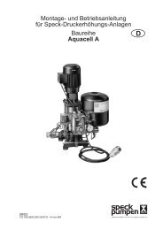
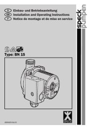
9. Associated documentation:<br />
Parts drawing<br />
38<br />
Z.-Nr. W 92.05.004<br />
Part Amount Description Material remark<br />
101 1 casing G-Cu Sn10 (Gbz-10)<br />
143 1 strainer basket PP<br />
(handle) PP<br />
160 1 lid PC<br />
161 1 gland housing G-Cu Sn10 (Gbz-10)<br />
174.2 1 diffuser<br />
BADU <strong>Bronze</strong> 8, 12, 15 PP TV 40<br />
BADU <strong>Bronze</strong> 20, 25 PP GF 30<br />
230 1 impeller<br />
BADU <strong>Bronze</strong> 8 PA 66 GF 30 / PC<br />
BADU <strong>Bronze</strong> 12 PA 66 GF 30 / PC<br />
BADU <strong>Bronze</strong> 15 PA 66 GF 30 / PC<br />
BADU <strong>Bronze</strong> 20 PP GF 30<br />
BADU <strong>Bronze</strong> 25 PP GF 30<br />
260 1 impeller seal<br />
only with BADU <strong>Bronze</strong> 20, 25 PP<br />
411.2 1 gasket centellen 200<br />
411.4 4 gasket PA 6<br />
412.1 1 O-ring perbunan<br />
412.2 1 O-ring perbunan<br />
412.3 1 O-ring<br />
only with BADU <strong>Bronze</strong> 8, 12, 15 perbunan<br />
412.3 1 collar<br />
only with BADU <strong>Bronze</strong> 20, 25 perbunan<br />
412.5 1 O-ring perbunan<br />
412.6 1 O-ring<br />
only with BADU <strong>Bronze</strong> 20, 25 viton<br />
433 1 mechanical seal coal/perbunan<br />
475 1 ceramic ring ceramic<br />
507 1 splash ring perbunan<br />
511 1 centering ring<br />
only with BADU <strong>Bronze</strong>, 8, 12, 15 PP TV 40<br />
515 1 staring<br />
only with BADU <strong>Bronze</strong> 20, 25 1.4310<br />
819 1 motor shaft 1.0543<br />
903 1 drain plug G-Cu Sn10 (Gbz-10)<br />
914.1 8 allen screws A4<br />
914.2 4 allen screws A4<br />
When ordering spare parts, please quote part number and pump type.<br />
39