

Catalog LV1 T 2009 Chapter 5 EN - Etnetera
Catalog LV1 T 2009 Chapter 5 EN - Etnetera
Catalog LV1 T 2009 Chapter 5 EN - Etnetera

Create successful ePaper yourself
Turn your PDF publications into a flip-book with our unique Google optimized e-Paper software.
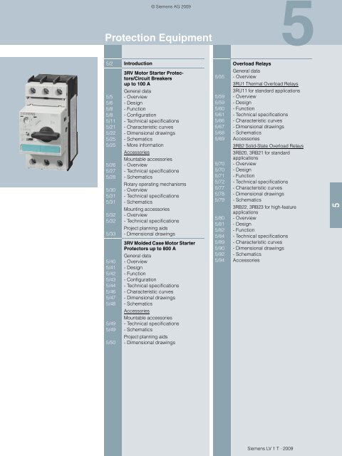
5/2 Introduction<br />
© Siemens AG <strong>2009</strong><br />
Protection Equipment<br />
5/5<br />
3RV Motor Starter Protectors/Circuit<br />
Breakers<br />
up to 100 A<br />
General data<br />
- Overview<br />
5/6 - Design<br />
5/8 - Function<br />
5/8 - Configuration<br />
5/11 - Technical specifications<br />
5/21 - Characteristic curves<br />
5/22 - Dimensional drawings<br />
5/25 - Schematics<br />
5/25 - More information<br />
Accessories<br />
Mountable accessories<br />
5/26 - Overview<br />
5/27 - Technical specifications<br />
5/28 - Schematics<br />
Rotary operating mechanisms<br />
5/30 - Overview<br />
5/31 - Technical specifications<br />
5/31 - Schematics<br />
Mounting accessories<br />
5/32 - Overview<br />
5/32 - Technical specifications<br />
Project planning aids<br />
5/33 - Dimensional drawings<br />
5/40<br />
3RV Molded Case Motor Starter<br />
Protectors up to 800 A<br />
General data<br />
- Overview<br />
5/41 - Design<br />
5/42 - Function<br />
5/43 - Configuration<br />
5/44 - Technical specifications<br />
5/46 - Characteristic curves<br />
5/47 - Dimensional drawings<br />
5/48 - Schematics<br />
Accessories<br />
Mountable accessories<br />
5/49 - Technical specifications<br />
5/49 - Schematics<br />
Project planning aids<br />
5/50 - Dimensional drawings<br />
Overload Relays<br />
General data<br />
5/55 - Overview<br />
Siemens LV 1 T · <strong>2009</strong><br />
5<br />
3RU1 Thermal Overload Relays<br />
3RU11 for standard applications<br />
5/59 - Overview<br />
5/59 - Design<br />
5/60 - Function<br />
5/61 - Technical specifications<br />
5/66 - Characteristic curves<br />
5/67 - Dimensional drawings<br />
5/68 - Schematics<br />
5/69 Accessories<br />
3RB2 Solid-State Overload Relays<br />
3RB20, 3RB21 for standard<br />
applications<br />
5/70 - Overview<br />
5/70 - Design<br />
5/71 - Function<br />
5/72 - Technical specifications<br />
5/77 - Characteristic curves<br />
5/78 - Dimensional drawings<br />
5/79 - Schematics<br />
3RB22, 3RB23 for high-feature<br />
applications<br />
5/80 - Overview<br />
5/81 - Design<br />
5/82 - Function<br />
5/84 - Technical specifications<br />
5/89 - Characteristic curves<br />
5/90 - Dimensional drawings<br />
5/92 - Schematics<br />
5/94 Accessories<br />
5
5<br />
Protection Equipment<br />
Introduction<br />
■ Overview<br />
Type 3RV10 3RV11 3RV13 3RV14 3RV16 3RV16 3RV17 3RV18<br />
3RV1 motor starter protectors/circuit breakers up to 100 A<br />
Applications<br />
System protection ✓1) ✓1) -- -- -- -- ✓ ✓<br />
Motor protection ✓ -- -- -- -- -- -- --<br />
Motor protection with<br />
overload relay function<br />
-- ✓ -- -- -- -- -- --<br />
Starter combinations -- -- ✓ -- -- -- -- --<br />
Transformer protection -- -- -- ✓ -- -- ✓ ✓<br />
Fuse monitoring -- -- -- -- ✓ -- -- --<br />
Voltage transformer<br />
circuit breakers<br />
for distance protection<br />
1) For symmetrical loading of the three phases.<br />
2) 500 V AC with molded-plastic enclosure.<br />
3) For overload protection of the motors, appropriate overload relays must be<br />
used.<br />
4) According to UL 489<br />
-at 480 Y/277 V AC: for size S0 50 kA, for size S3 65 kA;<br />
-at 480 V AC: for size S3 (10 A up to 30 A) 65 kA.<br />
5) Only lateral auxiliary switches can be fitted.<br />
5/2<br />
Siemens LV 1 T · <strong>2009</strong><br />
-- -- -- -- -- ✓ -- --<br />
Size S00, S0, S2, S3 S0, S2, S3 S0, S2, S3 S0, S2 S00 S00 S0, S3 S0<br />
Rated current In Size S00<br />
Size S0<br />
Size S2<br />
Size S3<br />
Rated operational voltage<br />
Ue acc. to IEC<br />
A<br />
A<br />
A<br />
A<br />
Up to 12<br />
Up to 25<br />
Up to 50<br />
Up to 100<br />
--<br />
Up to 25<br />
Up to 50<br />
Up to 100<br />
© Siemens AG <strong>2009</strong><br />
--<br />
Up to 25<br />
Up to 50<br />
Up to 100<br />
--<br />
Up to 20<br />
Up to 40<br />
--<br />
0.2<br />
--<br />
--<br />
--<br />
Up to 3<br />
--<br />
--<br />
--<br />
--<br />
Up to 22<br />
--<br />
Up to 70<br />
✓ Has this function or can use this accessory<br />
-- Does not have this function or cannot use this accessory<br />
--<br />
Up to 20<br />
--<br />
--<br />
V 690 AC 2) 690 AC 2) 690 AC 2) 690 AC 2) 690 AC 2) 400 AC 690 AC 690 AC<br />
Rated frequency Hz 50/60 50/60 50/60 50/60 50/60 16 2 / 3 ... 60 50/60 50/60<br />
Trip classes CLASS 10<br />
CLASS 20<br />
CLASS 10 -- CLASS 10 -- -- -- --<br />
Thermal<br />
A 0.11 ... 0.16 0.11 ... 0.16 None<br />
overload releases<br />
to<br />
to<br />
A 80 ... 100 80 ... 100<br />
3) 0.11 ... 0.16 0.2 1.4 ... 3 0.16 ... 70 0.16 ... 20<br />
to<br />
nonnon-<br />
Electronic trip units<br />
28 ... 40<br />
adjustableadjustable A multiple of the rated current 13 times 13 times 13 times 20 times 6 times 4 ... 7 times 13 times 20 times<br />
Short-circuit breaking<br />
capacity Icu at 400 V AC<br />
kA 50/100 50/100 50/100 50/100 100 50 4) 4)<br />
Accessories<br />
For sizes S00 S0 S2 S3 S0 S2 S3 S0 S2 S3 S0 S2 S00 S00 S0, S3 S0<br />
Auxiliary switches ✓ ✓ ✓ ✓ ✓ ✓ ✓ ✓ ✓ ✓ ✓ ✓ ✓ ✓ ✓ 5)<br />
✓ 5)<br />
Signal switches -- ✓ ✓ ✓ ✓ ✓ ✓ ✓ ✓ ✓ ✓ ✓ -- -- -- --<br />
Undervoltage trip units ✓ ✓ ✓ ✓ -- -- -- ✓ ✓ ✓ ✓ ✓ ✓ ✓ ✓ ✓<br />
Shunt trip units ✓ ✓ ✓ ✓ -- -- -- ✓ ✓ ✓ ✓ ✓ ✓ ✓ ✓ ✓<br />
Isolator modules -- ✓ ✓ -- ✓ ✓ -- ✓ ✓ -- ✓ ✓ -- -- -- --<br />
Insulated three-phase<br />
busbar system<br />
✓ ✓ ✓ -- -- ✓ -- ✓ ✓ -- ✓ ✓ ✓ ✓ -- --<br />
Busbar adapters ✓ ✓ ✓ ✓ ✓ ✓ ✓ ✓ ✓ ✓ ✓ ✓ ✓ ✓ -- --<br />
Door-coupling rotary<br />
operating mechanisms<br />
-- ✓ ✓ ✓ ✓ ✓ ✓ ✓ ✓ ✓ ✓ ✓ -- -- ✓ ✓<br />
Remote motorized<br />
operating mechanisms<br />
-- -- ✓ ✓ -- ✓ ✓ -- ✓ ✓ -- ✓ -- -- -- --<br />
Link modules ✓ ✓ ✓ ✓ ✓ ✓ ✓ ✓ ✓ ✓ ✓ ✓ ✓ ✓ -- --<br />
Enclosures for surface<br />
mounting<br />
✓ ✓ ✓ -- ✓ ✓ -- ✓ ✓ -- ✓ ✓ ✓ ✓ -- --<br />
Enclosures for flush mounting ✓ ✓ -- -- ✓ -- -- ✓ -- -- ✓ -- ✓ ✓ -- --<br />
Front plates ✓ ✓ ✓ ✓ ✓ ✓ ✓ ✓ ✓ ✓ ✓ ✓ ✓ ✓ -- --<br />
Infeed systems ✓ ✓ -- -- -- -- -- ✓ -- -- ✓ -- -- -- -- --
1) For overload protection of the motors, appropriate overload relays must be<br />
used; see <strong>Catalog</strong> LV 1 "Low-Voltage Controls",<br />
<strong>Chapter</strong> 5.<br />
Protection Equipment<br />
✓ Has this function or can use this accessory<br />
-- Does not have this function or cannot use this accessory<br />
Siemens LV 1 T · <strong>2009</strong><br />
Introduction<br />
Type 3RV10 3RV13<br />
3RV1 molded case motor starter protectors up to 800 A<br />
Applications<br />
Motor protection ✓ --<br />
Starter combinations -- ✓<br />
Switching capacity Standard switching capacity Standard switching capacity Increased switching<br />
capacity<br />
Size 3RV10 63 3RV10 73 3RV10 83 3RV13 53 3RV13 63 3RV13 73 3RV13 83 3RV13 64 3RV13 74<br />
Rated current In A 100, 160,<br />
200<br />
400 630 1 ... 32 100, 160,<br />
250<br />
400, 630 630, 800 100, 160,<br />
250<br />
400<br />
Rated operational voltage V<br />
Ue acc. to IEC<br />
690 AC 690 AC<br />
Rated frequency Hz 50/60 50/60<br />
Trip classes CLASS 10A<br />
CLASS 10<br />
CLASS 20<br />
CLASS 30<br />
--1) Thermal<br />
overload releases<br />
Electronic trip units<br />
A multiple of the<br />
rated current<br />
Short-circuit breaking<br />
capacity I cu at 400 V AC<br />
A<br />
A<br />
40 ... 100<br />
to<br />
252 ... 630<br />
© Siemens AG <strong>2009</strong><br />
None 1)<br />
Adjustable, 6 ... 13 times Nonadjustable<br />
1A...12.5A:<br />
13 times;<br />
adjustable<br />
20 A, 32 A:<br />
6 ... 12 times<br />
1 ... 10 times<br />
kA 120 120 100 85 120 120 100 200 200<br />
Trip units TU 4 TU 1:<br />
1A...12.5A;<br />
TU 2:<br />
20 A, 32 A<br />
TU 3<br />
Accessories<br />
For molded case motor<br />
starter protectors<br />
3RV10 63 3RV10 73 3RV10 83 3RV13 53 3RV13 63 3RV13 73 3RV13 83 3RV13 64 3RV13 74<br />
Auxiliary switches ✓ ✓ ✓ ✓ ✓ ✓ ✓ ✓ ✓<br />
Undervoltage trip units ✓ ✓ ✓ ✓ ✓ ✓ ✓ ✓ ✓<br />
Shunt trip units ✓ ✓ ✓ ✓ ✓ ✓ ✓ ✓ ✓<br />
Rotary operating<br />
mechanisms<br />
Connection methods<br />
✓ ✓ ✓ ✓ ✓ ✓ ✓ ✓ ✓<br />
Front-extended terminals ✓ ✓ -- ✓ ✓ ✓ -- ✓ ✓<br />
Front-accessible cable<br />
terminals<br />
✓ ✓ ✓ ✓ ✓ ✓ ✓ ✓ ✓<br />
Rear-accessible terminals ✓ ✓ ✓ ✓ ✓ ✓ ✓ ✓ ✓<br />
5/3<br />
5
5<br />
Protection Equipment<br />
Introduction<br />
Type<br />
Overload relays up to 630 A<br />
Applications<br />
3RU11 3RB20 3RB21 3RB22/3RB23<br />
System protection ✓ 1)<br />
✓ 1)<br />
✓ 1)<br />
✓ 1)<br />
Motor protection ✓ ✓ ✓ ✓<br />
Alternating current, three-phase ✓ ✓ ✓ ✓<br />
Alternating current, single-phase ✓ -- -- ✓<br />
Direct current ✓ -- -- --<br />
Size of contactor S00, S0, S2, S3 S00 ... S12 S00 ... S12 S00 ... S12<br />
Rated operational current Ie Size S00<br />
Size S0<br />
Size S2<br />
Size S3<br />
Size S6<br />
Size S10/S12,<br />
Size 14 (3TF6)<br />
1) The units are responsible in the main circuit for overload protection of the<br />
assigned electrical loads (e. g.motors), feeder cable and other switching<br />
and protection devices in the respective load feeder.<br />
2) Size S3 up to 1000 V AC.<br />
3) Size S2 (only with straight-through transformer), S3, S6, S10, S12<br />
up to 1000 V AC.<br />
4) With reference to the 3RB29 .6 current measuring modules.<br />
5) Stand-alone installation without accessories is possible.<br />
5/4<br />
Siemens LV 1 T · <strong>2009</strong><br />
A<br />
A<br />
A<br />
A<br />
A<br />
A<br />
Up to 12<br />
Up to 25<br />
Up to 50<br />
Up to 100<br />
Rated operational voltage U e V 690/1000 AC 2)<br />
--<br />
--<br />
Up to 12<br />
Up to 25<br />
Up to 50<br />
Up to 100<br />
Up to 200<br />
Up to 630<br />
690/1000 AC 3)<br />
Up to 12<br />
Up to 25<br />
Up to 50<br />
Up to 100<br />
Up to 200<br />
Up to 630<br />
690/1000 AC 3)<br />
Rated frequency Hz 50/60 50/60 50/60 50/60<br />
Trip classes CLASS 10 CLASS 10,<br />
CLASS 20<br />
Thermal<br />
overload releases<br />
Solid-state<br />
overload releases<br />
Rating for induction motor at<br />
400 V AC<br />
A<br />
A<br />
A<br />
A<br />
kW<br />
kW<br />
0.11 ... 0.16<br />
to<br />
80 ... 100<br />
-- 0.1 ... 0.4<br />
to<br />
160 ... 630<br />
0.04<br />
to<br />
45<br />
© Siemens AG <strong>2009</strong><br />
CLASS 5, 10, 20, 30<br />
Adjustable<br />
-- -- --<br />
0.04 ... 0.09<br />
Up to<br />
90 ... 450<br />
0.1 ... 0.4<br />
to<br />
160 ... 630<br />
0.04 ... 0.09<br />
to<br />
90 ... 450<br />
} Up to 25<br />
} Up to 100<br />
Up to 200<br />
Up to 630<br />
690/1000 AC 4)<br />
CLASS 5, 10, 20, 30<br />
Adjustable<br />
0.3 ... 3<br />
to<br />
63 ... 630<br />
0.09 ... 1.1<br />
to<br />
37 ... 450<br />
Accessories<br />
For sizes S00 S0 S2 S3 S00 S0 S2 S3 S6 S10/ S00 S0 S2 S3 S6 S10/ S00 S0 S2 S3 S6 S10/<br />
S12<br />
S12<br />
S12<br />
Terminal brackets for<br />
stand-alone installation<br />
✓ ✓ ✓ ✓ ✓ ✓<br />
5) 5) 5) 5) ✓ ✓ 5) 5) 5) 5) 5) 5) 5) 5) 5) 5)<br />
Mechanical RESET ✓ ✓ ✓ ✓ ✓ ✓ ✓ ✓ ✓ ✓ ✓ ✓ ✓ ✓ ✓ ✓ -- -- -- -- -- --<br />
Cable releases for RESET ✓ ✓ ✓ ✓ ✓ ✓ ✓ ✓ ✓ ✓ ✓ ✓ ✓ ✓ ✓ ✓ -- -- -- -- -- --<br />
Electrical remote RESET ✓ ✓ ✓ ✓ -- -- -- -- -- -- Integrated in the unit Integrated in the unit<br />
Terminal covers -- -- ✓ ✓ -- -- -- ✓ ✓ ✓ -- -- -- ✓ ✓ ✓ -- -- -- ✓ ✓ ✓<br />
Sealable covers<br />
for setting knobs<br />
Integrated in the unit ✓ ✓ ✓ ✓ ✓ ✓ ✓ ✓ ✓ ✓ ✓ ✓ ✓ ✓ ✓ ✓ ✓ ✓<br />
✓ Has this function or can use this accessory<br />
-- Does not have this function or cannot use this accessory
■ Overview<br />
3RV Motor Starter Protectors/Circuit Breakers up to 100 A<br />
The following illustrations show our 3RV1 motor starter<br />
protectors with the accessories which can be mounted for the<br />
various sizes, see also "Introduction" --> "Overview".<br />
S00 motor starter protectors with mountable accessories<br />
Motor starter protectors, sizes S0, S2 or S3, with mountable accessories<br />
Mountable accessories for all sizes S00 ... S3<br />
1<br />
2<br />
3<br />
4<br />
5<br />
Transverse auxiliary switch (can not be used with<br />
3RV17 and 3RV18 circuit breakers)<br />
Lateral auxiliary switch with 2 contacts<br />
Lateral auxiliary switch with 4 contacts<br />
Shunt release<br />
Undervoltage release<br />
For accessories, see page 5/26.<br />
2<br />
3<br />
2<br />
7<br />
3<br />
1<br />
1<br />
© Siemens AG <strong>2009</strong><br />
8<br />
4<br />
5<br />
4<br />
5<br />
6.1<br />
Mountable accessories<br />
6.1 Undervoltage release with<br />
leading auxiliary contacts<br />
6.2 Undervoltage release with<br />
leading auxiliary contacts<br />
7 Alarm switch<br />
8 Isolator module<br />
NSB0_01426a<br />
6.2<br />
for sizes<br />
S00<br />
S0 ... S3<br />
S0 ... S3<br />
S0 and S2<br />
Siemens LV 1 T · <strong>2009</strong><br />
General data<br />
5/5<br />
5
5<br />
3RV Motor Starter Protectors/Circuit Breakers up to 100 A<br />
General data<br />
Size S0 motor starter protector<br />
3RV1 motor starter protectors are compact, current limiting<br />
motor starter protectors which are optimized for load feeders.<br />
The motor starter protectors are used for switching and protecting<br />
induction motors of up to 45 kW at 400 V AC and for other<br />
loads with rated currents of up to 100 A.<br />
Type of construction<br />
The motor starter protectors are available in four sizes:<br />
Size S00 - width 45 mm,<br />
max. rated current 12 A,<br />
at 400 V AC suitable for induction motors up to 5.5 kW.<br />
Size S0 – width 45 mm,<br />
max. rated current 25 A,<br />
at 400 V AC suitable for induction motors up to 11 kW.<br />
Size S2 – width 55 mm,<br />
max. rated current 50 A,<br />
at 400 V AC suitable for induction motors up to 22 kW.<br />
Size S3 – width 70 mm,<br />
max. rated current 100 A,<br />
at 400 V AC suitable for induction motors up to 45 kW.<br />
Note<br />
"Increased safety" type of protection EEx e according to<br />
ATEX directive 94/9/EC<br />
The 3RV10 motor starter protectors are suitable for the overload<br />
protection of explosion-proof motors with "increased safety" type<br />
of protection EEx e;<br />
see <strong>Catalog</strong> LV 1 , <strong>Chapter</strong> 20 "Appendix" --> "Standards and<br />
Approvals" --> "Type Overview of Approved Devices for Explosion-Protected<br />
Areas (ATEX Explosion Protection)".<br />
■ Design<br />
Screw terminals<br />
3RV1 motor starter protectors of sizes S00 and S0 are fitted with<br />
terminals with captive screws and clamping pieces, allowing the<br />
connection of 2 conductors with different cross-sections.<br />
The box terminals of the S2 and S3 motor starter protectors also<br />
enable 2 conductors with different cross-sections to be connected.<br />
With the exception of S3 motor starter protectors which<br />
5/6<br />
Screw terminals<br />
Cage Clamp terminals<br />
These connections are indicated in the Technical<br />
specifications by orange backgrounds.<br />
Siemens LV 1 T · <strong>2009</strong><br />
© Siemens AG <strong>2009</strong><br />
are equipped with 4 mm Allen screws, all terminal screws are<br />
tightened with a Pozidriv screwdriver size 2.<br />
The box terminals of the S3 motor starter protectors can be removed<br />
in order to connect conductors with cable lugs or connecting<br />
bars. A terminal cover is available as touch protection<br />
and to ensure that the required clearances and creepage distances<br />
are maintained if the box terminals are removed.<br />
Cage Clamp terminals<br />
As an alternative to screw terminals, S00 motor starter protectors<br />
are also available with Cage Clamp terminals.<br />
Motor starter protector size S00 with Cage Clamp terminals<br />
This screwless connection method, already familiar from terminal<br />
blocks, clamps the conductors using a spring-type terminal<br />
and is shock-proof and vibration-proof.<br />
Motor starter protectors with Cage Clamp terminals allow independent<br />
connection of two conductors per terminal.<br />
Mounting<br />
The motor starter protectors are snap-fitted on a 35 mm standard<br />
mounting rail to <strong>EN</strong> 60715.<br />
3RB19 00-0B<br />
Push-in lugs for screwing the motor starter protector onto mounting<br />
plates.<br />
A standard mounting rail with a height of 15 mm is required for<br />
size S3 motor starter protectors. A 75 mm standard mounting rail<br />
can be used as an alternative for size S3.<br />
S2 and S3 motor starter protectors can also be screwed directly<br />
onto a base plate.<br />
The 3RB19 00-0B push-in lugs are available for screw mounting<br />
of S00 and S0 motor starter protectors.<br />
NSB0_01072a
3RV Motor Starter Protectors/Circuit Breakers up to 100 A<br />
3RV16 voltage transformer circuit breakers up to 3 A<br />
The voltage transformer circuit breaker widely corresponds with<br />
the SIRIUS 3RV1 motor starter protector, size S00. Two special<br />
features are taken into account for safe prevention of false tripping<br />
of the distance protection device.<br />
Auxiliary switch for blocking the distance protection<br />
The main contacts of the circuit breaker are opened if the voltage<br />
transformer circuit breaker is tripped or switched off. The<br />
distance protection would falsely interpret low impedance as a<br />
fault, which results in immediate power disconnection within only<br />
a few milliseconds.<br />
To prevent this false tripping, special auxiliary contacts with a<br />
time-dependent assignment to the circuit breaker's main contacts<br />
(see timing diagram) must be provided. The distance protection<br />
is blocked with the help of these auxiliary contacts and<br />
thus prevents false tripping.<br />
An auxiliary switch for blocking the distance protection device is<br />
available as 1 changeover contact fitted permanently in the<br />
= E + J= ? JI<br />
Timing diagram of auxiliary switches for blocking distance protection<br />
Installation guidelines for motor starter protectors/circuit breakers<br />
When mounting the motor starter protectors, the following clearances<br />
must be maintained to grounded or live parts and to cable<br />
ducts made of molded plastic.<br />
Motor starter protectors/circuit<br />
breakers<br />
1 NO 11-14<br />
1 NC 11-12<br />
(1 changeover contact)<br />
Type Size Ue Y<br />
X<br />
Z<br />
V<br />
mm mm mm<br />
3RV1. 1,<br />
3RV16 1.<br />
S00 Up to 690 20 70 9<br />
3RV1. 2,<br />
3RV17 21,<br />
3RV18 21<br />
S0 Up to 500<br />
Up to 690<br />
0<br />
Installation guidelines for motor starter protectors/circuit breakers with limiter function<br />
+20<br />
+20<br />
1<br />
1<br />
-10<br />
-10<br />
Siemens LV 1 T · <strong>2009</strong><br />
General data<br />
voltage transformer circuit breaker. This changeover contact<br />
can be used as 1 NO (11-14) or 1 NC (11-12). Thanks to the<br />
high contact stability of these auxiliary contacts at the lowest<br />
possible rated operational currents, they are also suitable for<br />
modern solid-state distance protection devices.<br />
The laterally mounted auxiliary switches of the SIRIUS range can<br />
be used for signaling purposes. They cannot be used for blocking<br />
the distance protection device.<br />
Impedance across the main contacts<br />
There is only minor current flow across the main contacts of the<br />
voltage transformer circuit breaker.<br />
To ensure reliable functioning of the distance protection, transfer<br />
resistance of the main contacts must be minimal and nearly constant<br />
throughout the endurance of the circuit breaker.<br />
This is implemented with suitable contacts and contact materials<br />
for the 3RV16 voltage transformer circuit breaker.<br />
ON OFF<br />
Tripping due to short-circuit<br />
0 J (ms) 0 J (ms) 0 J (ms)<br />
Distance to grounded or live parts and to molded-plastic cable ducts acc. to IEC 60947-2<br />
30<br />
50<br />
90<br />
90<br />
3RV1. 3 S2 Up to 690 50 140 10<br />
3RV1. 4 S3 Up to 240<br />
Up to 440<br />
Up to 500<br />
Up to 690<br />
3RV17 42 S3 Up to 240<br />
Up to 400<br />
Motor starter protectors/circuit<br />
breakers<br />
Type Size Ue V<br />
3RV1. 2 S0 Up to 500<br />
Up to 690<br />
50<br />
70<br />
110<br />
150<br />
90<br />
90<br />
167<br />
167<br />
167<br />
167<br />
167<br />
167<br />
9<br />
30<br />
--<br />
--<br />
10<br />
30<br />
10<br />
10<br />
Distance to grounded or live parts and to molded-plastic cable ducts acc. to IEC 60947-2<br />
Y<br />
mm<br />
40<br />
50<br />
X<br />
mm<br />
90<br />
90<br />
3RV1. 3 S2 Up to 690 50 140 10<br />
3RV1. 4 S3 Up to 500<br />
Up to 690<br />
110<br />
150<br />
167<br />
167<br />
Z<br />
mm<br />
10<br />
30<br />
10<br />
30<br />
© Siemens AG <strong>2009</strong><br />
Z<br />
Z Z<br />
1L1 3L2 5L3<br />
3RV1. ..<br />
2T1 4T2 6T3<br />
0<br />
1L1 3L2 5L3<br />
3RV1. ..<br />
2T1 4T2 6T3<br />
1L1 3L2 5L3 1L1 3L2 5L3<br />
3RV1. ..<br />
2T1 4T2 6T3<br />
Z<br />
3RV1. ..<br />
2T1 4T2 6T3<br />
1<br />
Y<br />
Y<br />
Y<br />
Y<br />
5<br />
5<br />
NSB0_01304d<br />
0<br />
3RV1. ..<br />
3RV1. ..<br />
NSB0_01071c<br />
X<br />
NSB0_01098c<br />
X<br />
5/7<br />
5
5<br />
3RV Motor Starter Protectors/Circuit Breakers up to 100 A<br />
General data<br />
Standard mounting for S0, S2 and S3 Structure for S0 for the setting ranges<br />
5.5 A ... 8 A up to 20 A ... 25 A for 690 V<br />
Wiring module<br />
Size S0: 3RV19 15-1A<br />
Size S2: 3RV19 35-1A<br />
Size S3: 3RV19 43-3A<br />
(Caution: The wiring module<br />
demands 10 mm spacing<br />
between the motor starter<br />
protectors)<br />
■ Function<br />
■ Configuration<br />
Trip units<br />
Prevention of unintended tripping<br />
3RV1 motor starter protectors are equipped with inverse-time In order to prevent premature tripping due to the integrated<br />
delayed overload release based on the bimetal principle and phase failure sensitivity, motor starter protectors should always<br />
with instantaneous electronic trip units (electromagnetic short- be connected to ensure current flows through all three main curcircuit<br />
releases).<br />
rent paths.<br />
The overload releases can be adjusted in accordance with the Short-circuit protection<br />
load current. The electronic trip units are permanently set to a<br />
value 13 times the rated current and thus enable trouble-free If a short-circuit occurs, the short-circuit releases of 3RV1 motor<br />
starting of motors.<br />
starter protectors isolate the faulty load feeder from the network<br />
and thus prevent further damage.<br />
Motor starter protectors for line-side transformer protection are<br />
set to 20 times the rated current to prevent tripping as a result of Motor starter protectors with a short-circuit breaking capacity of<br />
high transformer inrush current.<br />
50 kA or 100 kA are virtually short-circuit resistant at a voltage of<br />
400 V AC, since higher short-circuit currents are not to be ex-<br />
The scale cover can be sealed to prevent unauthorized adjustpected in practice.<br />
ments to the set current.<br />
Motor protection<br />
Trip classes<br />
The tripping characteristics of 3RV10/3RV11 motor starter pro-<br />
The trip classes of thermally delayed trip units are based on the tectors are designed mainly to protect induction motors.<br />
tripping time (tA ) at 7.2 times the set current in cold state (excerpt<br />
from IEC 60947-4):<br />
The motor starter protectors are therefore also referred to as<br />
motor-protective circuit breakers.<br />
CLASS 10A: 2 s < tA
System protection<br />
3RV Motor Starter Protectors/Circuit Breakers up to 100 A<br />
The 3RV10 and 3RV11 motor starter protectors for motor<br />
protection are also suitable for plant protection.<br />
In order to prevent premature tripping due to phase failure sensitivity,<br />
the three conducting paths must always be uniformly<br />
loaded. The conducting paths must be connected in series in<br />
the case of single-phase loads.<br />
The 3RV17 and 3RV18 circuit breakers are suitable for system<br />
protection and at the same time they are approved as circuit<br />
breakers according to UL 489 and CSA C22.2 No. 5-02 for<br />
100 % rated current (100 % rated breaker).<br />
Short-circuit protection for starter combinations<br />
The 3RV13 motor starter protectors for starter combinations in<br />
sizes S0, S2 and S3 provide short-circuit protection with the help<br />
of a contactor and overload relay combination.<br />
Like the motor starter protectors for motor protection, they are<br />
equipped with short-circuit releases which are permanently set<br />
to a value equivalent to 13 times the rated current of the motor<br />
starter protectors. They are not equipped with overload<br />
releases.<br />
On overload, the overload relay triggers the contactor, the motor<br />
starter protector remains closed.<br />
Only when a short-circuit occurs in the feeder does the motor<br />
starter protector trip as well.<br />
The motor starter protector for starter combinations must always<br />
be used in combination with an overload relay because the<br />
motor starter protector alone cannot protect the motor and itself<br />
against overload.<br />
Transformer protection<br />
When control transformers are protected on the line side, the<br />
high inrush currents generated at the time the transformers are<br />
switched on often cause spurious tripping in the protection<br />
mechanisms.<br />
3RV14 motor starter protectors in sizes S0 and S2 and 3RV18<br />
circuit breakers in size S0 for protecting transformers are therefore<br />
fitted with electronic trip units which are permanently set in<br />
the factory to a value equivalent to 20 times the rated current. For<br />
the 3RV17 circuit breakers in sizes S0 and S3 these electronic<br />
trip units are set in the factory to approximately 13 times the<br />
rated current.<br />
Motor starter protectors can thus be used to provide line-side<br />
protection for transformers, the inrush peak currents of which are<br />
up to 30 times the rated current.<br />
The 3RV17 and 3RV18 are approved as circuit breakers according<br />
to UL 489 and CSA 22.2 No. 5-02 for the protection of transformers,<br />
the 3RV18 circuit breakers size S0 are designed specially<br />
for the protection of transformers with high inrush current.<br />
This version of motor starter protector is not necessary in the<br />
case of control-power transformers with low inrush currents,<br />
such as control transformers from Siemens. 3RV1 motor starter<br />
protectors for motor protection can be used in this case.<br />
Main and EMERG<strong>EN</strong>CY-STOP switches<br />
The 3RV10, 3RV11, 3RV13, 3RV14 and 3RV16 motor starter<br />
protectors comply with the isolating function to IEC 60947-2,<br />
therefore they can be used – taking IEC 60204-1 into account –<br />
as main and EMERG<strong>EN</strong>CY-STOP switches.<br />
3RV19 .6-2. door-coupling rotary operating mechanisms for<br />
heavy duty also comply with the requirements for the isolating<br />
function.<br />
Fuse monitoring<br />
The 3RV16 11-0BD10 motor starter protector size S00 is used for<br />
fuse monitoring.<br />
© Siemens AG <strong>2009</strong><br />
Siemens LV 1 T · <strong>2009</strong><br />
General data<br />
A fuse is connected in parallel with each conducting path of the<br />
motor starter protector. When a fuse blows, the current flows<br />
through the parallel conducting path and trips the motor starter<br />
protector.<br />
The 3RV16 11-0BD10 motor starter protector for fuse monitoring<br />
must be equipped with a transverse or lateral auxiliary switch<br />
(see "Accessories") that signals a tripping operation of the motor<br />
starter protector and thus the tripping of the fuse, or switches off<br />
all poles of the disrupted electric circuit with the help of an appropriate<br />
switching device.<br />
Motor starter protector for fuse monitoring<br />
Notes on safety<br />
When monitoring fuses with safety isolating functions, a warning<br />
sign must be affixed near the fuses indicating that voltage may<br />
still be present through the parallel circuit of the monitoring<br />
equipment assumed to be isolated after the fuse has been removed<br />
and if the monitoring equipment is not switched off.<br />
We recommend the following text for this warning:<br />
Caution!<br />
For safety isolation, also switch off fuse monitoring equipment<br />
with the item code ......<br />
The 3RV16 11-0BD10 motor starter protector for fuse monitoring<br />
is suitable for the following voltages: AC 50 Hz/60 Hz from 24 V<br />
to 690 V and up to 450 V DC. Fuse monitoring with<br />
3RV16 11-0BD10 motor starter protector is not permissible in<br />
feeders with power controllers that can induce DC feedback of<br />
higher values when an error occurs.<br />
With parallel cables and meshed systems, the motor starter<br />
protector will only trip, and a signal will be output to indicate this,<br />
if the voltage difference across the motor starter protector is at<br />
least 24 V.<br />
Use of IT systems (IT networks)<br />
3RV1 motor starter protectors are suitable for operation in<br />
IT systems according to IEC 60947-2. In the event of a threepole<br />
short-circuit, their response in this system is the same as in<br />
others: Therefore, the same short-circuit breaking capacity Icu and Ics applies, (see "Technical specifications").<br />
An initial fault (ground fault) does not necessarily force immediate<br />
disconnection of the network when operating IT systems. If a<br />
second independent error occurs (ground fault), the switching<br />
capacity of the motor starter protector might be reduced.<br />
This is the case if both ground faults occur in different phases<br />
and if one of the ground faults occurs on the input side and the<br />
other on the outgoing terminal of the motor starter protector.<br />
In order to maintain the short-circuit function of the motor starter<br />
protector even with two independent ground faults (double<br />
ground faults), the reduced short-circuit breaking capacity with<br />
double ground faults must be taken into account in IT systems<br />
IcuIT (see "Technical specifications"). If a ground fault is instantaneously<br />
recognized and remedied (ground-fault monitoring), the<br />
risk of double ground fault and thus reduced short-circuit breaking<br />
capacity IcuIT can be minimized.<br />
5/9<br />
5
5<br />
3RV Motor Starter Protectors/Circuit Breakers up to 100 A<br />
General data<br />
Switching of direct current<br />
3RV1 motor starter protectors for alternating currents are also<br />
suitable for DC switching.<br />
The maximum permissible DC voltage per conducting path<br />
must, however, be adhered to. Higher voltages require a series<br />
connection with 2 or 3 conducting paths.<br />
Example circuit for size S00 to S3 3RV1 motor starter protectors<br />
Example circuit for size S00<br />
to S3 3RV1 motor starter protectors<br />
L+ L<br />
NSB0_00001a M<br />
L+ L<br />
NSB0_00002a M<br />
L+ L<br />
NSB0_00003a<br />
1) It is assumed that this circuit always provides safe disconnection even in<br />
the event of a double ground fault that bridges two contacts.<br />
3RV16 voltage transformer circuit breakers up to 3 A<br />
The voltage transformer circuit breaker protects the secondary<br />
side of voltage transformers used to connect protection equipment<br />
with voltage-dependent starting. The circuit breaker is<br />
used for distance protection with low-impedance starting. Special<br />
auxiliary contacts reliably prevent low-impedance starting<br />
from triggering distance protection if only one fault has occurred<br />
in the transformer line.<br />
The voltage transformer circuit breaker can also be used to<br />
safely disconnect the distance protection device from the voltage<br />
transformer. In this case, the special auxiliary contacts also<br />
prevent false tripping of the distance protection.<br />
Additional fuses are not required. A "Fuse Failure Monitor" (FFM)<br />
is also not required.<br />
5/10<br />
M<br />
Siemens LV 1 T · <strong>2009</strong><br />
Maximum permitted<br />
DC voltage U e<br />
© Siemens AG <strong>2009</strong><br />
Notes<br />
The response values of the overload release remain unchanged;<br />
the response values of a short-circuit release increase by approximately<br />
30 % for DC. The example circuits for DC switching<br />
can be seen in the table below.<br />
150 V DC Three-pole switching, non-grounded system1) If there is no possibility of a ground fault, or if every ground fault is rectified immediately<br />
(ground-fault monitoring), then the maximum permitted DC voltage can be tripled.<br />
300 V DC Two-pole switching, grounded system<br />
The grounded pole is always assigned to the individual conducting path, so that there<br />
are always 2 conducting paths in series in the event of a ground fault.<br />
450 V DC Single-pole switching, grounded system<br />
3 conducting paths in series. The grounded pole is assigned to the unconnected conducting<br />
path.
3RV Motor Starter Protectors/Circuit Breakers up to 100 A<br />
■ Technical specifications<br />
Short-circuit breaking capacity Icu, Ics acc. to IEC 60947-2<br />
This table shows the rated ultimate short-circuit breaking<br />
capacity Icu and the rated service short-circuit breaking<br />
capacity Ics of the 3RV1 motor starter protectors with different<br />
inception voltages dependent of the rated current In of the motor<br />
starter protectors.<br />
Motor starter protector infeed is permissible at the upper or<br />
lower terminals without restricting the rated data. If the short-circuit<br />
current at the place of installation exceeds the rated shortcircuit<br />
breaking capacity of the motor starter protector as specified<br />
in the table, a back-up fuse is required. Alternatively, a<br />
Motor starter<br />
protectors/circuit<br />
breakers<br />
Rated current<br />
I n<br />
Up to 240 V AC 1) Up to<br />
400 V 1) /415 V AC 2)<br />
I cu I cs Max. fuse<br />
(gL/gG)<br />
Siemens LV 1 T · <strong>2009</strong><br />
General data<br />
motor starter protector with a limiter function can be connected<br />
upstream.<br />
The maximum rated current for the back-up fuse is specified in<br />
the tables. The rated ultimate short-circuit breaking capacity<br />
then applies as specified on the fuse.<br />
Fuseless construction<br />
Motor starter protector contactor combinations for short-circuit<br />
currents up to 50 kA can be ordered in the form of fuseless load<br />
feeders according to <strong>Chapter</strong> 6.<br />
Up to<br />
440 V 1) /460 V AC 2)<br />
Up to<br />
500 V 1) /525 V AC 2)<br />
Up to 690 V AC 1)<br />
(these values do not apply to 3RV17 42 circuit breakers)<br />
Icu Ics Max. fuse<br />
(gL/gG) 3)<br />
Icu Ics Max. fuse<br />
(gL/gG) 3)<br />
Icu Ics Max. fuse<br />
(gL/gG) 3)<br />
Icu Ics Max.<br />
fuse<br />
(gL/gG) 3)4)<br />
Type<br />
Size S00<br />
A kA kA A kA kA A kA kA A kA kA A kA kA A<br />
3RV10, 0.16 ... 1 100 100 ° 100 100 ° 100 100 ° 100 100 ° 100 100 °<br />
3RV16 11-0BD10 1.25; 1.6 100 100 ° 100 100 ° 100 100 ° 100 100 ° 2 2 20<br />
2; 2.5 100 100 ° 100 100 ° 100 100 ° 10 10 35 2 2 35<br />
3.2; 4 100 100 ° 100 100 ° 50 10 40 3 3 40 2 2 40<br />
5; 6.3 100 100 ° 100 100 ° 50 10 50 3 3 50 2 2 50<br />
8 100 100 ° 50 12.5 80 50 10 63 3 3 63 2 2 63<br />
10 100 100 ° 50 12.5 80 10 10 63 3 3 63 2 2 63<br />
Size S0<br />
12 100 100 ° 50 12.5 80 10 10 80 3 3 80 2 2 80<br />
3RV1. 2,<br />
3RV17 21,<br />
3RV18 21<br />
© Siemens AG <strong>2009</strong><br />
0.16 ... 1.6 100 100 ° 100 100 ° 100 100 ° 100 100 ° 100 100 °<br />
2; 2.5 100 100 ° 100 100 ° 100 100 ° 100 100 ° 8 8 25<br />
3.2 100 100 ° 100 100 ° 100 100 ° 100 100 ° 8 8 32<br />
4; 5 100 100 ° 100 100 ° 100 100 ° 100 100 ° 6 3 32<br />
6.3 100 100 ° 100 100 ° 100 100 ° 100 100 ° 6 3 50<br />
8 100 100 ° 100 100 ° 50 25 63 42 21 63 6 3 50<br />
10 100 100 ° 100 100 ° 50 25 80 42 21 63 6 3 50<br />
12.5 100 100 ° 100 100 ° 50 25 80 42 21 80 6 3 63<br />
16 100 100 ° 50 25 100 50 10 80 10 5 80 4 2 63<br />
20 100 100 ° 50 25 125 50 10 80 10 5 80 4 2 63<br />
22; 25 100 100 ° 50 25 125 50 10 100 10 5 80 4 2 63<br />
Size S2<br />
3RV1. 3 16 100 100 ° 50 25 100 50 25 100 12 6 63 5 3 63<br />
20 100 100 ° 50 25 100 50 25 100 12 6 80 5 3 63<br />
25 100 100 ° 50 25 100 50 15 100 12 6 80 5 3 63<br />
32 100 100 ° 50 25 125 50 15 125 10 5 100 4 2 63<br />
40; 45 100 100 ° 50 25 160 50 15 125 10 5 100 4 2 63<br />
Size S3<br />
50 100 100 ° 50 25 160 50 15 125 10 5 100 4 2 80<br />
3RV1. 41 40 100 100 ° 50 25 125 50 20 125 12 6 100 6 3 63<br />
50 100 100 ° 50 25 125 50 20 125 12 6 100 6 3 80<br />
63 100 100 ° 50 25 160 50 20 160 12 6 100 6 3 80<br />
75 100 100 ° 50 25 160 50 20 160 8 4 125 5 3 100<br />
90; 100 100 100 ° 50 25 160 50 20 160 8 4 125 5 3 125<br />
Size S3, with increased<br />
switching capacity<br />
3RV1. 42 /<br />
3RV17 42 5)<br />
16/10<br />
20/15<br />
100<br />
100<br />
100<br />
100<br />
°<br />
°<br />
100<br />
100<br />
50<br />
50<br />
°<br />
°<br />
100<br />
100<br />
50<br />
50<br />
°<br />
°<br />
30<br />
30<br />
15<br />
15<br />
80<br />
80<br />
12<br />
12<br />
7<br />
7<br />
63<br />
63<br />
25/20 100 100 ° 100 50 ° 100 50 ° 30 15 80 12 7 63<br />
32/25 100 100 ° 100 50 ° 100 50 ° 22 11 100 12 7 63<br />
40/30 100 100 ° 100 50 ° 100 50 ° 18 9 160 12 6 80<br />
50/35 ... 40 100 100 ° 100 50 ° 100 50 ° 15 7.5 160 10 5 100<br />
63/45 ... 50 100 100 ° 100 50 ° 70 50 200 15 7.5 160 7.5 4 100<br />
75/60 100 100 ° 100 50 ° 70 50 200 10 5 160 6 3 125<br />
90/70 100 100 ° 100 50 ° 70 50 200 10 5 160 6 3 160<br />
100/ -- 100 100 ° 100 50 ° 70 50 200 10 5 160 6 3 160<br />
Short-circuit resistant up to at least 50 kA<br />
° No back-up fuse required, since short-circuit resistant up to 100 kA<br />
1) 10 % overvoltage.<br />
4) Alternatively, fuseless limiter combinations for 690 V AC can also be used.<br />
2) 5 % overvoltage.<br />
5) The values for the 3RV17 42 circuit breakers have been tested only up to<br />
3) Back-up fuse only required if the short-circuit current at the place of<br />
400 V/415 V AC; values > 440 V AC on request.<br />
installation > Icu. 5/11<br />
5
5<br />
3RV Motor Starter Protectors/Circuit Breakers up to 100 A<br />
General data<br />
Short-circuit breaking capacity IcuIT in the IT system<br />
(IT network) according to IEC 60947-2<br />
3RV1 motor starter protectors are suitable for operation in<br />
IT systems. Values valid for triple-pole short-circuit are Icu up to<br />
Ics . In case of double ground fault on different phases at the input<br />
and output side of a motor starter protector, the special<br />
short-circuit breaking capacity IcuIT applies. The specifications<br />
in the table below apply to 3RV1 motor starter protectors.<br />
Motor starter<br />
protectors<br />
Short-circuit resistant up to at least 50 kA<br />
° No back-up fuse required, since short-circuit resistant up to 100 kA<br />
1)<br />
10 % overvoltage.<br />
2)<br />
5 % overvoltage.<br />
3)<br />
Back-up fuse only required, if short-circuit current at the place of<br />
installation > IcuIT .<br />
4)<br />
Alternatively, fuseless limiter combinations for 690 V AC can also be used.<br />
5/12<br />
Rated current<br />
I n<br />
Siemens LV 1 T · <strong>2009</strong><br />
© Siemens AG <strong>2009</strong><br />
In the colored areas, IcuIT is 100 kA, or in some ranges it is 50 kA.<br />
Therefore the motor starter protectors are short-circuit resistant<br />
in these ranges.<br />
If the short-circuit current at the place of installation exceeds the<br />
rated short-circuit breaking capacity of the motor starter protector<br />
as specified in the table, a back-up fuse is required. The maximum<br />
rated current for the back-up fuse is specified in the tables.<br />
The rated short-circuit breaking capacity then applies as<br />
specified on the fuse.<br />
Up to 240 V AC 1) Up to 400 V 1) /415 V AC 2) Up to 500 V 1) /525 V AC 2) Up to 690 V AC 1)<br />
IcuIT Max. fuse<br />
(gL/gG) 3)<br />
IcuIT Max. fuse<br />
(gL/gG) 3)<br />
IcuIT Max. fuse<br />
(gL/gG) 3)4)<br />
IcuIT Max. fuse<br />
(gL/gG) 3)<br />
Type<br />
Size S00<br />
A kA A kA A kA A kA A<br />
3RV10, 0.16 ... 0.63 100 ° 100 ° On request On request On request On request<br />
3RV16 11-0BD10 0.8; 1 100 ° 100 °<br />
1.25; 1.6 100 ° 2 20<br />
2; 2.5 100 ° 2 35<br />
3.2; 4 100 ° 2 40<br />
5; 6.3 100 ° 2 50<br />
8; 10 50 80 2 63<br />
Size S0<br />
12 50 80 2 80<br />
3RV1. 2 0.16 ... 0.63 100 ° 100 ° On request On request On request On request<br />
0.8; 1 100 ° 100 °<br />
1.25; 1.6 100 ° 100 °<br />
2; 2.5 100 ° 8 25<br />
3.2 100 ° 8 32<br />
4; 5 100 ° 6 32<br />
6.3 ... 10 100 ° 6 50<br />
12.5 100 ° 6 63<br />
Size S2<br />
16 ... 25 50 80 4 63<br />
3RV1. 3 16 50 100 8 100 6 80 5 63<br />
20 50 125 8 100 6 80 5 63<br />
25 50 125 8 100 6 80 5 63<br />
32 50 125 6 125 4 100 3 80<br />
Size S3<br />
40 ... 50 50 160 6 125 4 100 3 80<br />
3RV1. 41 40 50 125 10 63 5 50 5 50<br />
50 50 125 8 80 3 63 3 63<br />
63 50 160 6 80 3 63 3 63<br />
75 50 160 5 100 2 80 2 80<br />
90; 100 50 160 5 125 2 100 2 100<br />
Size S3, with increased<br />
switching capacity<br />
3RV1. 42 16 100 ° 12 63 6 50 6 50<br />
20 100 ° 12 63 6 50 6 50<br />
25 100 ° 12 63 6 50 6 50<br />
32 100 ° 12 63 6 50 6 50<br />
40 100 ° 12 80 6 63 6 63<br />
50 100 ° 10 100 4 80 4 80<br />
63 100 ° 7.5 100 4 80 4 80<br />
75 100 ° 6 125 3 100 3 100<br />
90 100 ° 6 160 3 125 3 125<br />
100 100 ° 6 160 3 125 3 125
3RV Motor Starter Protectors/Circuit Breakers up to 100 A<br />
Limiter function with standard devices for 500 V AC and<br />
690 V AC acc. to IEC 60947-2<br />
The table shows the rated ultimate short-circuit breaking capacity<br />
Icu and the rated service short-circuit breaking capacity Ics with an upstream standard motor starter protector that fulfills the<br />
limiter function at 500 V AC and 690 V AC. The short-circuit<br />
breaking capacity can be increased significantly with an upstream<br />
standard motor starter protector.<br />
© Siemens AG <strong>2009</strong><br />
Short-circuit resistant up to 100 kA<br />
° No back-up fuse required, since short-circuit resistant up to 100 kA<br />
1) 10 % overvoltage.<br />
2) 5 % overvoltage.<br />
Siemens LV 1 T · <strong>2009</strong><br />
General data<br />
The motor starter protector which is connected downstream<br />
must be set to the rated current of the load.<br />
With motor starter protector combination assemblies, note the<br />
clearance to grounded parts and between the motor starter protectors.<br />
Short-circuit resistant wiring between the motor starter<br />
protectors must be ensured. The motor starter protectors can be<br />
mounted side by side in a modular arrangement.<br />
Standard motor starter protectors Rated current I n Up to 500 V 1) /525 V AC 2) Up to 690 V AC 1)<br />
With limiter function<br />
rated current In Icu Ics Icu Ics Type<br />
Size S0<br />
Type A kA kA kA kA<br />
3RV10 2 3RV13 21-4DC10 Up to 1 ° ° ° °<br />
1.25 ° ° ° °<br />
In = 25 A 1.6<br />
2<br />
°<br />
°<br />
°<br />
°<br />
°<br />
50<br />
°<br />
25<br />
2.5 ° ° 50 25<br />
3.2 ° ° 50 25<br />
4 ° ° 50 25<br />
5 ° ° 50 25<br />
6.3 ° ° 50 25<br />
8 100 50 20 10<br />
10 100 50 20 10<br />
12.5 100 50 20 10<br />
16 100 50 20 10<br />
20 100 50 20 10<br />
22 100 50 20 10<br />
Size S2<br />
25 100 50 20 10<br />
3RV10 3 3RV13 31-4HC10 16 100 50 50 25<br />
20 100 50 50 25<br />
In = 50 A 25 100 50 50 25<br />
32 100 50 50 25<br />
40 100 50 50 25<br />
Size S3<br />
50 100 50 50 25<br />
3RV10 4 3RV13 41-4HC10 32 100 50 50 25<br />
40 100 50 50 25<br />
In = 50 A 50 100 50 50 25<br />
3RV13 41-4MC10 50 100 50 50 25<br />
63 100 50 50 25<br />
In = 100 A 75 100 50 50 25<br />
90 100 50 50 25<br />
100 100 50 50 25<br />
5/13<br />
5
5<br />
3RV Motor Starter Protectors/Circuit Breakers up to 100 A<br />
General data<br />
General technical specifications<br />
Type 3RV1. 1 1) Standards<br />
3RV1. 2 3RV1. 3 3RV1. 4 3RV17 21 3RV17 42 3RV18 21<br />
IEC 60947-1, <strong>EN</strong> 60947-1 (VDE 0660 Part 100) Yes<br />
IEC 60947-2, <strong>EN</strong> 60947-2 (VDE 0660 Part 101) Yes<br />
IEC 60947-4-1, <strong>EN</strong> 60947-4-1 (VDE 0660 Part 102) Yes No<br />
UL 489, CSA C22.2-No.5-02 No Yes<br />
Size S00 S0 S2 S3 S0 S3 S0<br />
Number of poles 3<br />
Max. rated current In max<br />
(= max. rated operational current Ie )<br />
A 12 25 50 100 22 70 20<br />
Permissible ambient temperature<br />
Storage/transport °C –50 ... +80<br />
–20 ... +70 2)<br />
Operation<br />
Permissible rated current at inside temperature of control cabinet<br />
°C<br />
+60°C % 100<br />
+70°C<br />
Motor starter protectors/circuit breakers inside enclosure<br />
Permissible rated current at ambient temperature of enclosure<br />
% 87<br />
+35°C % 100<br />
+60°C % 87<br />
Rated operational voltage Ue Acc. to IEC V AC 690 3)<br />
Acc. to UL/CSA V AC 600<br />
Rated frequency Hz 50/60<br />
Rated insulation voltage U i V 690<br />
Rated impulse withstand voltage U imp kV 6<br />
Utilization categories<br />
IEC 60947-2 (motor starter protector/circuit breaker) A<br />
IEC 60947-4-1 (motor starter) AC -3 --<br />
Trip classes CLASS Acc. to IEC 60947-4-1 10 10/20 --<br />
DC short-circuit breaking capacity (time constant t = 5 ms)<br />
1 conducting path 150 V DC kA 10<br />
2 conducting paths in series 300 V DC kA 10<br />
3 conducting paths in series 450 V DC kA 10<br />
Power loss P v per motor starter<br />
protector/circuit breaker<br />
Dependent on rated current I n<br />
(upper setting range)<br />
For footnotes see page 5/15. For short-circuit breaking capacity I cu , I cs<br />
see table of same name.<br />
5/14<br />
Siemens LV 1 T · <strong>2009</strong><br />
© Siemens AG <strong>2009</strong><br />
I n : ... 1.25 A W 5 --<br />
I n : 1.6 ... 6.3 A W 6<br />
I n : 8 ... 12 A W 7<br />
Rper conducting path = P/I2 x 3<br />
In : ... 0.63 A<br />
In : 0.8 ... 6.3 A<br />
In : 8 ... 16 A<br />
In : 20 ... 25 A<br />
W<br />
W<br />
W<br />
W<br />
--<br />
--<br />
--<br />
--<br />
5<br />
6<br />
7<br />
8<br />
--<br />
--<br />
--<br />
--<br />
5<br />
6<br />
7<br />
8<br />
--<br />
--<br />
--<br />
--<br />
5<br />
6<br />
7<br />
8<br />
In : ... 25 A<br />
In: 32 A<br />
In : 40 ... 50 A<br />
W<br />
W<br />
W<br />
--<br />
--<br />
--<br />
12<br />
15<br />
20<br />
--<br />
--<br />
--<br />
In : ... 63 A<br />
In : 75 and 90 A<br />
In : ... 100 A<br />
W<br />
W<br />
W<br />
--<br />
--<br />
--<br />
20<br />
30<br />
38<br />
--<br />
--<br />
--<br />
In: ... 10 A<br />
In : ... 35 A<br />
In : ... 70 A<br />
W<br />
W<br />
W<br />
--<br />
--<br />
--<br />
8<br />
12<br />
21<br />
--<br />
--<br />
--<br />
Shock resistance Acc. to IEC 60068-2-27 g/ms 25/11 (square and sine pulse)<br />
Degree of protection Acc. to IEC 60529 IP20 4)<br />
Touch protection Acc. to <strong>EN</strong> 50274 Finger-safe<br />
Temperature compensation Acc. to IEC 60947-4-1 °C –20 ... +60<br />
Phase failure sensitivity Acc. to IEC 60947-4-1 Yes No<br />
Explosion protection – safe operation of motors with<br />
"increased safety" type of protection<br />
Yes, for 3RV10 (CLASS 10) No<br />
EC type test certificate number acc. to<br />
DMT 02 ATEX F 001 II (2) GD,<br />
directive 94/9/EC (ATEX)<br />
DMT 02 ATEX F 001 N1 II (2) GD<br />
Isolating function Acc. to IEC 60947-2 Yes<br />
Main and EMERG<strong>EN</strong>CY-STOP switch<br />
characteristics5) Acc. to IEC 60204-1<br />
(VDE 0113)<br />
Yes<br />
Protective separation between main and<br />
auxiliary circuits, required for PELV<br />
applications<br />
Acc. to <strong>EN</strong> 60947-1<br />
Up to 400V+10% Yes<br />
Up to 415 V + 5 % (higher voltages on request) Yes<br />
Permissible mounting positions Any, acc. to IEC 60447 start command "I" right-hand side or top<br />
Mechanical endurance Operating cycles 100 000 50 000 100 000 50 000 100 000<br />
Electrical endurance Operating cycles 100 000 25 000 100 000 25 000 100 000<br />
Max. switching frequency per hour (motor starts) 1/h 15<br />
--<br />
--
3RV Motor Starter Protectors/Circuit Breakers up to 100 A<br />
Conductor cross-sections of main circuit<br />
Type 3RV1. 3RV1. 2 3RV1. 3 3RV1. 4/<br />
3RV17 42<br />
Connection type Screw terminals Screw terminals<br />
with box terminal<br />
Footnotes for page 5/14:<br />
1) For 3RV16 voltage transformer circuit breakers see more<br />
"Technical specifications".<br />
2) Above +60 °C current reduction.<br />
3) 500 V with molded-plastic enclosure.<br />
4) Terminal compartment IP00 (exception: 3RV10 11-..2. motor starter<br />
protectors with Cage Clamp terminals degree of protection IP20).<br />
5) With appropriate accessories.<br />
© Siemens AG <strong>2009</strong><br />
Siemens LV 1 T · <strong>2009</strong><br />
General data<br />
3RV17 21,<br />
3RV18 21<br />
Terminal screw Pozidriv size 2 Pozidriv size 2 4 mm Allen screw Pozidriv size 2<br />
Prescribed tightening torque<br />
Conductor cross-sections<br />
(1 or 2 conductors connectable)<br />
Nm 0.8 ... 1.2 2...2.5 3 ... 4.5 4...6 2.5 ... 3<br />
Solid mm 2<br />
2 x (0.5 ... 1.5) 4) ,<br />
2 x (0.75 ... 2.5) 4) 2 x (1 ... 2.5)4) ,<br />
2 x (2.5 ... 6) 4)<br />
2 x (0.75 ... 16) 2 x (2.5 ... 16) 1...10,<br />
max. 2 x 10<br />
Finely stranded with end sleeve mm 2<br />
2 x (0.5 ... 1.5) 4) ,<br />
2 x (0.75 ... 2.5) 4) 2 x (1 ... 2.5)4) ,<br />
2 x (2.5 ... 6) 4)<br />
2 x (0.75 ... 16),<br />
1 x (0.75 ... 25)<br />
2 x (2.5 ... 35),<br />
1 x (2.5 ... 50)<br />
1...16,<br />
max. 6 + 16<br />
Stranded mm 2<br />
2 x (0.5 ... 1.5) 4) ,<br />
2 x (0.75 ... 2.5) 4) 2 x (1 ... 2.5)4) ,<br />
2 x (2.5 ... 6) 4)<br />
2 x (0.75 ... 25),<br />
1 x (0.75 ... 35)<br />
2 x (10 ... 50),<br />
1 x (10 ... 70)<br />
1.5 ... 25,<br />
max. 10 + 25<br />
AWG cables, solid or stranded AWG 2 x (18 ... 14) 2 x (14 ... 10) 2 x (18 ... 2), 2 x (10 ... 1/0), 2 x (14 ... 10)<br />
1 x (18 ... 2) 1 x (10 ... 2/0)<br />
Ribbon cable conductors (number x width x thickness) mm<br />
Removable box terminals<br />
-- 2 x (6 x 9 x 0.8) --<br />
1)<br />
With copper bars2) -- -- 18 x 10 --<br />
With cable lugs 3)<br />
-- -- Up to 2 x 70 --<br />
Connection type Cage Clamp terminals 5)6)<br />
Conductor cross-sections<br />
(1 or 2 conductors connectable)<br />
Solid mm 2<br />
2 x (0.25 ... 2.5) --<br />
Finely stranded with end sleeve mm2 2 x (0.25 ... 1.5) --<br />
Finely stranded without end sleeve mm 2<br />
2 x (0.25 ... 2.5) --<br />
AWG cables, solid or stranded AWG 2 x (24 ... 14) --<br />
Max. external diameter of the conductor insulation mm 3.6<br />
Footnotes for page 5/15:<br />
1) Cable lug and busbar connection possible after removing the box<br />
terminals.<br />
2) If bars larger than 12 mm x 10 mm are connected, a 3RT19 46-4EA1<br />
terminal cover is needed to comply with the phase clearance.<br />
3) If conductors larger than 25 mm 2 are connected, a 3RT19 46-4EA1<br />
terminal cover is needed to comply with the phase clearance.<br />
4) If two different conductor cross-sections are connected to one clamping<br />
point, both cross-sections must lie in the range specified. If identical crosssections<br />
are used, this restriction does not apply.<br />
5) For corresponding 8WA2 803 or 8WA2 880 opening tools<br />
see <strong>Catalog</strong> LV 1, <strong>Chapter</strong> 5 "Protection Equipment" --><br />
"3RV Motor Starter Protectors up to 100 A" --> "Accessories".<br />
6) With conductor cross-sections of ≤ 1mm 2 an "insulation stop" must be<br />
used (see <strong>Chapter</strong> 3 "Contactors and Contactor Assemblies" --><br />
"Accessories").<br />
5/15<br />
5
5<br />
3RV Motor Starter Protectors/Circuit Breakers up to 100 A<br />
General data<br />
Permissible rated data of devices approved for North America (UL/CSA)<br />
Motor starter protectors of the 3RV1 series are approved for<br />
UL/CSA and according to UL 508 and CSA C22.2 No. 14 they<br />
can be used on their own or as a load feeder in combination with<br />
a contactor.<br />
3RV1 motor starter protectors as "Manual Motor Controllers"<br />
If used as a "Manual Motor Controller", the motor starter protector<br />
is always operated in combination with an upstream short-circuit<br />
protection device. Approved fuses or a circuit breaker according<br />
to UL 489/CSA C22.2 No. 5-02 can be used. These devices<br />
must be dimensioned according to the National Electrical Code<br />
(UL) or Canadian Electrical Code (CSA).<br />
Motor starter<br />
protectors<br />
1) hp rating = Power rating in horse power (maximum motor rating).<br />
2) FLA = Full Load Amps/Motor full load current.<br />
3) Complies with "short-circuit breaking capacity" according to UL/CSA.<br />
5/16<br />
Siemens LV 1 T · <strong>2009</strong><br />
hp rating 1) for FLA 2)<br />
max.<br />
© Siemens AG <strong>2009</strong><br />
Rated current<br />
I n<br />
These motor starter protectors can be used as "Manual Motor<br />
Controllers" for "Group Installations", as "Manual Motor Controllers<br />
Suitable for Tap Conductor Protection in Group Installations"<br />
and as "Self-Protected Combination Motor Controllers" (Type E).<br />
Approval of the 3RV as a Manual Motor Controller can be found<br />
under the following file numbers:<br />
UL File No. 47705, CCN: NLRV,<br />
CSA Master Contract 165071, Product Class: 3211 05.<br />
240 V AC 480 V AC 600 V AC<br />
UL CSA UL CSA UL CSA<br />
I 3)<br />
bc Ibc<br />
3)<br />
Ibc<br />
3)<br />
Ibc<br />
3)<br />
Ibc<br />
3)<br />
Ibc<br />
3)<br />
Type V 1-phase 3-phase A kA kA kA kA kA kA<br />
Size S00<br />
3RV10 11, 3RV16 11-0BD10 0.16 ... 2 65 65 65 65 10 10<br />
FLA<br />
2.5 65 65 65 65 10 10<br />
2) max. 12 A, 115 1/2 -- 3.2 65 65 65 65 10 10<br />
600 V 200 1 1/2 3<br />
4 65 65 65 65 10 10<br />
NEMA size 00 230 2 3 5 65 65 65 65 10 10<br />
460 -- 7 1/2 6.3 65 65 65 65 10 10<br />
575/600 -- 10<br />
8 65 65 65 65 10 10<br />
10 65 65 65 65 10 10<br />
Size S0<br />
12 65 65 65 65 10 10<br />
3RV10 21/3RV11 21, 3RV13 21 0.16 ... 3.2 65 65 65 65 30 30<br />
FLA<br />
4 65 65 65 65 30 30<br />
2) max. 25 A, 115 2 -- 5 65 65 65 65 30 30<br />
600 V 200 3 5<br />
6.3 65 65 65 65 30 30<br />
NEMA size 1 230 3 7 1/2 8 65 65 65 65 30 30<br />
460 -- 15 10 65 65 65 65 30 30<br />
575/600 -- 20<br />
12.5 65 65 65 65 30 30<br />
16 65 65 65 65 10 10<br />
20 65 65 65 65 10 10<br />
22 65 65 65 65 10 10<br />
Size S2<br />
25 65 65 65 65 10 10<br />
3RV10 31/3RV11 31, 3RV13 31 16 65 65 65 65 30 25<br />
FLA<br />
20 65 65 65 65 30 25<br />
2) max. 50 A, 115 3 -- 25 65 65 65 65 30 25<br />
600 V 200 7 1/2 15<br />
32 65 65 65 65 30 25<br />
NEMA size 2 230 10 20 40 65 65 65 65 30 25<br />
460 -- 40 45 65 65 65 65 30 25<br />
Size S3<br />
575/600 -- 50 50 65 65 65 65 30 25<br />
3RV10 41/3RV10 42, 3RV11 42, 3RV13 41/3RV13 42 16 65 65 65 65 30 30<br />
FLA<br />
20 65 65 65 65 30 30<br />
2) max. 99 A, 115 7 1/2 -- 25 65 65 65 65 30 30<br />
600 V 200 20 30<br />
32 65 65 65 65 30 30<br />
NEMA size 3 230 20 40 40 65 65 65 65 30 30<br />
460 -- 75 50 65 65 65 65 30 30<br />
575/600 -- 100<br />
63 65 65 65 65 30 30<br />
75 65 65 65 65 30 30<br />
90 65 65 65 65 10 10<br />
100 65 65 65 65 10 10
3RV Motor Starter Protectors/Circuit Breakers up to 100 A<br />
3RV10 motor starter protectors as "Manual Motor Controllers Suitable for Tap Conductor Protection in Group Installations"<br />
The application as "Manual Motor Controllers Suitable for Tap<br />
Conductor Protection in Group Installations" is only available<br />
from UL.<br />
CSA does not recognize this approval! When the motor starter<br />
protector is used as a "Manual Motor Controller Suitable for Tap<br />
Conductor Protection in Group Installations", it must always be<br />
combined with upstream short-circuit protection. As short-circuit-protection<br />
device, approved fuses or a motor starter<br />
Motor starter<br />
protectors<br />
hp rating 1) for FLA 2)<br />
max.<br />
1)<br />
hp rating = Power rating in horse power (maximum motor rating).<br />
2)<br />
FLA = Full Load Amps/Motor full load current.<br />
3)<br />
Complies with "short-circuit breaking capacity" according to UL.<br />
© Siemens AG <strong>2009</strong><br />
Siemens LV 1 T · <strong>2009</strong><br />
General data<br />
protector according to UL 489 can be used.<br />
These devices must be dimensioned according to the National<br />
Electrical Code.<br />
The 3RV10 motor starter protectors are approved as "Manual<br />
Motor Controllers Suitable for Tap Conductor Protection in Group<br />
Installations" under the following file number:<br />
UL File No. 47705, CCN: NLRV.<br />
Rated current I n 240 V AC Up to 480 V AC Up to 600 V AC<br />
UL UL UL<br />
I bc 3) Ibc 3) Ibc 3)<br />
Type V 1-phase 3-phase A kA kA kA<br />
Size S00<br />
3RV10 11 0.16 ... 0.8 65 65 10<br />
FLA<br />
1 65 65 10<br />
2) max. 8 A, 115 1/3 -- 1.25 65 65 10<br />
480 V 200 3/4 2<br />
2 65 65 10<br />
NEMA size 0 230 1 2 2.5 65 65 10<br />
460 -- 5 3.2 65 65 10<br />
575/600 -- --<br />
4 65 65 10<br />
5 65 65 10<br />
6.3 65 65 10<br />
Size S0<br />
8 65 65 10<br />
3RV10 21 0.16 ... 1.6 65 65 30<br />
FLA<br />
2 65 65 30<br />
2) max. 115 2 -- 2.5 65 65 30<br />
22 A, 480 V<br />
200 3 5<br />
3.2 65 65 30<br />
12.5 A, 600 V 230 3 7 1/2 4 65 65 30<br />
460 -- 15 5 65 65 30<br />
NEMA size 1 575/600 -- 10<br />
6.3 65 65 30<br />
8 65 65 30<br />
10 65 65 30<br />
Size S2<br />
12.5 65 65 30<br />
3RV10 31 16 65 65 25<br />
FLA<br />
20 65 65 25<br />
2) max. 115 3 -- 25 65 65 25<br />
50 A, 600 V 200 7 1/2 15<br />
32 65 65 25<br />
NEMA size 2 230 10 20 40 65 65 25<br />
460 -- 40 45 65 65 25<br />
Size S3<br />
575/600 -- 50 50 65 65 25<br />
3RV10 4. 16 65 65 30<br />
FLA<br />
20 65 65 30<br />
2) max. 115 7 1/2 -- 25 65 65 30<br />
100 A, 480 V<br />
200 20 30<br />
32 65 65 30<br />
75 A, 600 V 230 20 40 40 65 65 30<br />
460 -- 75 50 65 65 30<br />
NEMA size 3 575/600 -- 75<br />
63 65 65 30<br />
75 65 65 30<br />
90 65 65 --<br />
100 65 65 --<br />
5/17<br />
5
5<br />
3RV Motor Starter Protectors/Circuit Breakers up to 100 A<br />
General data<br />
3RV10 motor starter protectors as "Self-Protected Combination Motor Controllers (Type E)"<br />
A line-side 1-inch clearance in air and 2-inch creepage distance<br />
is required for "Self-Protected Combination Motor Controllers" for<br />
approval according to UL 508.<br />
Therefore, 3RV10 motor starter protectors of size S0 and S3 are<br />
approved to UL 508 in combination with the terminal blocks<br />
listed below.<br />
The basic units of the 3RV10 motor starter protectors size S2<br />
comply with the required clearance in air and creepage<br />
distances.<br />
Motor starter<br />
protectors<br />
5/18<br />
Siemens LV 1 T · <strong>2009</strong><br />
hp rating 1) for FLA 2)<br />
max.<br />
© Siemens AG <strong>2009</strong><br />
Rated current<br />
I n<br />
CSA does not demand these extended air/creepage distances.<br />
According to CSA, these terminal blocks can be omitted when<br />
the device is used as a "Self-Protected Combination Motor<br />
Controller".<br />
The 3RV10 motor starter protectors are approved as "Self-Protected<br />
Combination Motor Controllers" under the following file<br />
numbers:<br />
UL File No. E156943, CCN: NKJH,<br />
CSA Master Contract 165071, Product Class: 3211 08.<br />
Up to 240 V AC Up to 480 Y/277 V AC Up to 600 Y/347 V AC<br />
UL CSA UL CSA UL CSA<br />
I 3)<br />
bc Ibc<br />
3)<br />
Ibc<br />
3)<br />
Ibc<br />
3)<br />
Ibc<br />
3)<br />
Ibc<br />
3)<br />
Type<br />
Size S0<br />
V 1-phase 3-phase A kA kA kA kA kA kA<br />
3RV10 21 + 3RV19 28-1H<br />
1)<br />
hp rating = Power rating in horse power (maximum motor rating).<br />
2)<br />
FLA = Full Load Amps/Motor full load current.<br />
3)<br />
Complies with "short-circuit breaking capacity" according to UL/CSA.<br />
4)<br />
Not required for CSA.<br />
4)<br />
0.16 ... 1.6 65 65 65 65 30 30<br />
FLA<br />
2 65 65 65 65 30 30<br />
2) max. 115 2 -- 2.5 65 65 65 65 30 30<br />
22 A, 480 V<br />
200 3 5<br />
3.2 65 65 65 65 30 30<br />
12.5 A, 600 V 230 3 7 1/2 4 65 65 65 65 30 30<br />
460 -- 15 5 65 65 65 65 30 30<br />
NEMA size 1 575/600 -- 10<br />
6.3 65 65 65 65 30 30<br />
8 65 65 65 65 30 30<br />
10 65 65 65 65 30 30<br />
12.5 65 65 65 65 30 30<br />
16 65 65 65 65 -- --<br />
20 65 65 65 65 -- --<br />
Size S2<br />
22 65 65 65 65 -- --<br />
3RV10 31 16 65 65 65 65 25 25<br />
FLA<br />
20 65 65 65 65 25 25<br />
2) max. 115 3 -- 25 65 65 65 65 25 25<br />
50 A, 600 V 200 7 1/2 15<br />
32 65 65 65 65 25 25<br />
NEMA size 2 230 10 20 40 65 65 65 65 25 25<br />
460 -- 40 45 65 65 65 65 25 25<br />
Size S3<br />
575/600 -- 50 50 65 65 65 65 25 25<br />
3RV10 41 + 3RT19 46-4GA07 4)<br />
16 65 65 65 65 30 30<br />
FLA<br />
20 65 65 65 65 30 30<br />
2) max. 115 10 -- 25 65 65 65 65 30 30<br />
100 A, 480 V<br />
200 20 30<br />
32 65 65 65 65 30 30<br />
75 A, 600 V 230 20 40 40 65 65 65 65 30 30<br />
460 -- 75 50 65 65 65 65 30 30<br />
NEMA size 3 575/600 -- 75<br />
63 65 65 65 65 30 30<br />
75 65 65 65 65 30 30<br />
90 65 65 65 65 -- --<br />
100 65 65 65 65 -- --
3RV Motor Starter Protectors/Circuit Breakers up to 100 A<br />
3RV17 and 3RV18 circuit breakers<br />
These circuit breakers are approved according to UL 489 and<br />
CSA C22.2 No. 5-02 for 100 % rated current (100 % rated<br />
breaker). They can be used therefore as upstream short-circuit<br />
protective devices for "Manual Motor Controllers" and "Manual<br />
Motor Controllers Suitable for Tap Conductor Protection in Group<br />
Installations".<br />
© Siemens AG <strong>2009</strong><br />
Siemens LV 1 T · <strong>2009</strong><br />
General data<br />
The 3RV17 and 3RV18 circuit breakers are approved under the<br />
following file numbers:<br />
UL File No. E235044, CCN: DIVQ,<br />
CSA Master Contract 165071, Product Class: 1432 01.<br />
Circuit breakers Rated current I n 240 V AC 480 Y/277 V AC 480 V AC 600 Y/347 V AC<br />
UL CSA UL CSA UL CSA UL CSA<br />
I bc 1) Ibc 1) Ibc 1) Ibc 1) Ibc 1) Ibc 1) Ibc 1) Ibc 1)<br />
Type<br />
Size S0<br />
A kA kA kA kA kA kA kA kA<br />
3RV17 21 0.16 50 50 50 50 -- -- 10 10<br />
0.2 50 50 50 50 -- -- 10 10<br />
0.25 50 50 50 50 -- -- 10 10<br />
0.32 50 50 50 50 -- -- 10 10<br />
0.4 50 50 50 50 -- -- 10 10<br />
0.5 50 50 50 50 -- -- 10 10<br />
0.63 50 50 50 50 -- -- 10 10<br />
0.8 50 50 50 50 -- -- 10 10<br />
1 50 50 50 50 -- -- 10 10<br />
1.25 50 50 50 50 -- -- 10 10<br />
1.6 50 50 50 50 -- -- 10 10<br />
2 50 50 50 50 -- -- 10 10<br />
2.5 50 50 50 50 -- -- 10 10<br />
3.2 50 50 50 50 -- -- 10 10<br />
4 50 50 50 50 -- -- 10 10<br />
5 50 50 50 50 -- -- 10 10<br />
6.3 50 50 50 50 -- -- 10 10<br />
8 50 50 50 50 -- -- 10 10<br />
10 50 50 50 50 -- -- -- --<br />
12.5 50 50 50 50 -- -- -- --<br />
15 50 50 50 50 -- -- -- --<br />
20 50 50 50 50 -- -- -- --<br />
22 50 50 50 50 -- -- -- --<br />
3RV18 21 0.16 50 50 50 50 -- -- 10 10<br />
0.2 50 50 50 50 -- -- 10 10<br />
0.25 50 50 50 50 -- -- 10 10<br />
0.32 50 50 50 50 -- -- 10 10<br />
0.4 50 50 50 50 -- -- 10 10<br />
0.5 50 50 50 50 -- -- 10 10<br />
0.63 50 50 50 50 -- -- 10 10<br />
0.8 50 50 50 50 -- -- 10 10<br />
1 50 50 50 50 -- -- 10 10<br />
1.25 50 50 50 50 -- -- 10 10<br />
1.6 50 50 50 50 -- -- 10 10<br />
2 50 50 50 50 -- -- 10 10<br />
2.5 50 50 50 50 -- -- 10 10<br />
3.2 50 50 50 50 -- -- 10 10<br />
4 50 50 50 50 -- -- 10 10<br />
5 50 50 50 50 -- -- 10 10<br />
6.3 50 50 50 50 -- -- 10 10<br />
8 50 50 50 50 -- -- -- --<br />
10 50 50 50 50 -- -- -- --<br />
12.5 50 50 50 50 -- -- -- --<br />
15 50 50 50 50 -- -- -- --<br />
Size S3<br />
20 50 50 50 50 -- -- -- --<br />
3RV17 42 10 65 65 65 65 65 65 20 20<br />
15 65 65 65 65 65 65 20 20<br />
20 65 65 65 65 65 65 20 20<br />
25 65 65 65 65 65 65 20 20<br />
30 65 65 65 65 65 65 20 20<br />
35 65 65 65 65 -- -- 20 20<br />
40 65 65 65 65 -- -- 20 20<br />
45 65 65 65 65 -- -- 20 20<br />
50 65 65 65 65 -- -- 20 20<br />
60 65 65 65 65 -- -- 20 20<br />
70 65 65 65 65 -- -- 10 10<br />
1) Complies with "short-circuit breaking capacity" according to UL.<br />
5/19<br />
5
5<br />
3RV Motor Starter Protectors/Circuit Breakers up to 100 A<br />
General data<br />
Rated data of the auxiliary switches and signal switches<br />
Type 3RV19 Lateral auxiliary<br />
switch with<br />
1 NO + 1 NC, 2 NO,<br />
2 NC, 2 NO + 2 NC<br />
Signal switches<br />
Voltage transformer circuit breakers<br />
General technical specifications<br />
1) If two different conductor cross-sections are connected to one clamping<br />
point, both cross-sections must lie in the range specified. If identical crosssections<br />
are used, this restriction does not apply.<br />
5/20<br />
Siemens LV 1 T · <strong>2009</strong><br />
Transverse auxiliary switches with<br />
1 CO contact 1 NO + 1 NC, 2 NO<br />
Max. rated voltage<br />
Acc. to NEMA (UL) V AC 600 250<br />
Acc. to NEMA (CSA) V AC 600 250<br />
Uninterrupted current A 10 5 2.5<br />
Switching capacity A600<br />
Q300<br />
Type 3RV16 11-1AG14 3RV16 11-1CG14 3RV16 11-1DG14<br />
Rated current In A 1.4 2.5 3<br />
Ambient temperature<br />
During storage/transport °C –50 ... +80<br />
During operation °C –20 ... +60 (up to +70 °C is possible with current reduction)<br />
Rated operational voltage Ue V 400<br />
Rated frequency Hz 16.66 ... 60<br />
Rated insulation voltage Ui V 690<br />
Short-circuit breaking capacity I cu at 400 V AC kA 50<br />
Set value of the thermal overload release A 1.4 2.5 3<br />
Response value of the instantaneous electronic trip unit A 6 ± 20 % 10.5 ± 20 % 20 ± 20 %<br />
Tripping time of the instantaneous electronic trip unit ms Approx. 6 at 12 A Approx. 6 at 20 A Approx. 6 at 40 A<br />
Internal resistance<br />
© Siemens AG <strong>2009</strong><br />
In cold state Ω >0.25± 6.5 %<br />
In heated state Ω >0.30± 6.5 %<br />
Shock resistance acc. to IEC 68 Part 2-27 g 15<br />
Degree of protection acc. to IEC 60529 IP20<br />
Touch protection acc. to <strong>EN</strong> 50274<br />
Endurance<br />
Finger-safe<br />
Mechanical Operating<br />
cycles<br />
10000<br />
Electrical Operating<br />
cycles<br />
10000<br />
Permissible mounting positions Any<br />
Type<br />
Conductor cross-sections, main circuit, 1 or 2 conductors<br />
3RV16 11-1AG14 3RV16 11-1CG14 3RV16 11-1DG14<br />
Connection type Screw terminals<br />
Terminal screw<br />
Conductor cross-sections<br />
Pozidriv size 2<br />
Solid mm 2<br />
2 x (0.5 ... 1.5) 1) , 2 x (0.75 ... 2.5) 1) , max. 4<br />
Finely stranded with end sleeve mm2 2 x (0.5 ... 1.5) 1) , 2 x (0.75 ... 2.5) 1)<br />
Stranded mm 2<br />
2 x (0.5 ... 1.5) 1) , 2 x (0.75 ... 2.5) 1) Auxiliary switch for blocking the distance protection<br />
, max. 4<br />
With defined lateral assignment for blocking distance protection 1 changeover contact (for use as 1 NO or 1 NC)<br />
Rated operational voltage Ue (AC voltage) V 250<br />
Rated operational current Ie /AC-14 at Ue = 250 V A 0.5<br />
Rated operational current Ie /AC-14 at Ue = 125 V A 1<br />
Rated operational voltage Ue (DC voltage L/R 200 ms) V 250<br />
Rated operational current Ie /DC-13 at Ue = 250 V A 0.27<br />
Rated operational current Ie /DC-13 at Ue = 125 V<br />
Short-circuit protection for auxiliary circuit<br />
A 0.44<br />
Melting fuse gL/gG A 10<br />
Miniature circuit breaker, C characteristic<br />
Auxiliary switches for other signaling purposes<br />
For technical specifications see "Mountable Accessories"<br />
A 6 (prospective short-circuit current < 0.4 kA)<br />
B600<br />
R300<br />
C300<br />
R300
■ Characteristic curves<br />
3RV Motor Starter Protectors/Circuit Breakers up to 100 A<br />
The time/current characteristic, the current limiting characteristics<br />
and the I2t characteristic curves were determined according<br />
to <strong>EN</strong>/IEC 60947.<br />
The tripping characteristic of the inverse-time delayed overload<br />
release (thermal overload releases, 'a' releases) for DC and AC<br />
with a frequency of 0 Hz to 400 Hz applies for the time/current<br />
characteristic.<br />
The characteristic curves apply to the cold state; at operating<br />
temperature, the tripping times of the thermal releases are reduced<br />
to approximately 25 %.<br />
Under normal operating conditions, all three poles of the device<br />
must be loaded. The three main current paths must be connected<br />
in series in order to protect single-phase or DC loads.<br />
With two-pole and three-pole loading, the maximum deviation in<br />
the tripping time of 3 times the setting current and upwards is<br />
±20 % and thus in accordance with <strong>EN</strong> 60079.<br />
The tripping characteristics for the instantaneous, electromagnetic<br />
electronic trip units (short-circuit releases, 'n' releases) are<br />
based on the rated current In that also represents the maximum<br />
value of the setting range for motor starter protectors with adjustable<br />
overload releases. If the current is set to a lower value, the<br />
tripping current of the 'n' release is increased by a corresponding<br />
factor.<br />
The characteristic curves of the electromagnetic electronic trip<br />
units apply to frequencies of 50 Hz/60 Hz. Appropriate correction<br />
factors must be used for lower frequencies down to<br />
16 2 / 3 Hz, for higher frequencies up to 400 Hz and for DC.<br />
Opening time<br />
10 000<br />
100<br />
min 5000<br />
60<br />
40<br />
2000<br />
1000<br />
10<br />
500<br />
5<br />
200<br />
2<br />
100<br />
1<br />
50<br />
20<br />
10<br />
5<br />
2<br />
1<br />
0,5<br />
0,2<br />
0,1<br />
0,05<br />
0,02<br />
0,01<br />
0,005<br />
0,002<br />
2-pole<br />
loading<br />
Class 10<br />
3-pole<br />
loading<br />
Class 20<br />
0,001<br />
0,6 1 2 3 4 6 8 10<br />
0,8<br />
3-pole<br />
loading<br />
Class 10<br />
NSB0_00004b<br />
20 30 40 60 80 x n<br />
Current<br />
Schematic representation of typical time/current characteristic of 3RV10<br />
The above characteristic curve for the motor starter protector relates<br />
to a specific setting range. It is, however, also valid as a<br />
schematic representation of motor starter protectors with other<br />
current ranges.<br />
© Siemens AG <strong>2009</strong><br />
Siemens LV 1 T · <strong>2009</strong><br />
General data<br />
Time/current characteristic curves, current limiting characteristic<br />
curves and I 2 t curves can be ordered from "Technical<br />
Assistance":<br />
Either by e-mail to:<br />
technical-assistance@siemens.com<br />
Or on the Internet:<br />
http:/www.siemens.com/automation/service&support<br />
3RV16 voltage transformer circuit breakers up to 3 A<br />
The specified tripping characteristics of the thermal overload release<br />
(a) correspond to the mean value of the scatter band in the<br />
cold state. At operating temperature, these times are reduced to<br />
approximately 25 % of the specified values.<br />
The characteristic curves below are schematic representations.<br />
Precise characteristic curves can be ordered from "Technical<br />
Assistance":<br />
Either by e-mail to:<br />
technical-assistance@siemens.com<br />
Or on the Internet:<br />
http:/www.siemens.com/automation/service&support<br />
1000<br />
s<br />
100<br />
10<br />
1<br />
0,1<br />
0,01<br />
1<br />
1<br />
a)<br />
2 3<br />
b)<br />
2 4 6 10 20 4060A100 1 1.4 A / 6 A<br />
2 2.5 A / 10.5 A<br />
3 3 A / 20 A<br />
a) Thermal overload release<br />
b) Instantaneous electromagnetic trip unit<br />
NSB0_01352b<br />
5/21<br />
5
5<br />
3RV Motor Starter Protectors/Circuit Breakers up to 100 A<br />
General data<br />
■ Dimensional drawings<br />
3RV1 motor starter protectors, size S00<br />
3RV10 11, 3RV16<br />
2)<br />
1) 9) 6) 3) 4)<br />
9<br />
18<br />
45 18<br />
3RV1 motor starter protectors, size S0<br />
3RV10 21, 3RV13 21, 3RV14 21<br />
1)<br />
3RV1 motor starter protectors, size S2<br />
5/22<br />
45 12<br />
90<br />
45<br />
3,5<br />
8)<br />
5<br />
Siemens LV 1 T · <strong>2009</strong><br />
62<br />
70<br />
7) 76<br />
NSB0_00026d<br />
105<br />
2) 8) 6) 3)<br />
4)<br />
14<br />
72<br />
12<br />
45<br />
90<br />
97<br />
45<br />
18 45 18<br />
5 56<br />
9<br />
69<br />
80<br />
91<br />
3RV10 31, 3RV13 31, 3RV14 31<br />
125<br />
90<br />
1) 2)<br />
9<br />
7)<br />
20<br />
18 55 18<br />
45<br />
85<br />
140<br />
7)<br />
109<br />
127<br />
132<br />
144<br />
NSB0_00027c<br />
25<br />
5<br />
5)<br />
106<br />
121<br />
3) 4)<br />
12<br />
6)<br />
5<br />
8<br />
© Siemens AG <strong>2009</strong><br />
25<br />
5<br />
5)<br />
1) Lateral auxiliary switch, 2-pole.<br />
2) Lateral auxiliary switch, 4-pole.<br />
3) Auxiliary releases.<br />
4) Transverse auxiliary switch.<br />
5) Drilling pattern.<br />
6) Push-in lugs for screw mounting.<br />
7) Only for undervoltage release<br />
with leading auxiliary switch.<br />
8) Standard mounting rail TH 35 according<br />
to <strong>EN</strong> 60715.<br />
9) Lockable in neutral position<br />
with shackle diameter 3.5 mm ... 4.5 mm.<br />
NSB0_00028b<br />
130<br />
1) Lateral auxiliary switch, 2-pole.<br />
2) Signal switch or lateral auxiliary switch,<br />
4-pole.<br />
3) Auxiliary releases.<br />
4) Transverse auxiliary switch.<br />
5) Drilling pattern.<br />
6) Push-in lugs for screw mounting.<br />
7) Standard mounting rail TH 35 according<br />
to <strong>EN</strong> 60715.<br />
8) Lockable in neutral position<br />
with shackle diameter 3.5 mm ... 4.5 mm.<br />
30<br />
5<br />
5)<br />
1) Lateral auxiliary switch, 2-pole.<br />
2) Signal switch or lateral auxiliary switch,<br />
4-pole.<br />
3) Auxiliary releases.<br />
4) Transverse auxiliary switch.<br />
5) Drilling pattern.<br />
6) Standard mounting rail TH 35 according<br />
to <strong>EN</strong> 60715.<br />
7) Lockable in neutral position<br />
with shackle diameter 3.5 mm ... 4.5 mm.
3RV Motor Starter Protectors/Circuit Breakers up to 100 A<br />
3RV1 motor starter protectors, size S3<br />
3RV104, 3RV134<br />
165<br />
90<br />
1) 2)<br />
9<br />
18 70 18<br />
45<br />
116<br />
150<br />
3RV11 motor starter protectors, size S0<br />
3RV11 21<br />
1)<br />
9<br />
2)<br />
18<br />
8)<br />
3RV11 motor starter protectors, size S2<br />
3RV11 31<br />
1)<br />
125<br />
9<br />
2)<br />
18<br />
7)<br />
8) 6) 3)<br />
7)<br />
45<br />
55<br />
20<br />
20<br />
12<br />
3)<br />
45<br />
90<br />
97<br />
20<br />
3)<br />
12<br />
45<br />
90<br />
140<br />
12<br />
45<br />
7)<br />
8<br />
6)<br />
7<br />
5<br />
5 55<br />
69<br />
80<br />
91<br />
6)<br />
5<br />
8<br />
72 4)<br />
121<br />
109<br />
127<br />
132<br />
144<br />
NSB0_00030c<br />
146<br />
132<br />
153<br />
157<br />
169<br />
106<br />
© Siemens AG <strong>2009</strong><br />
25<br />
5<br />
4)<br />
5)<br />
NSB0_00031d<br />
130<br />
4)<br />
NSB0_00029c<br />
155<br />
30<br />
5<br />
5)<br />
1) Lateral auxiliary switch, 2-pole.<br />
2) Signal switch or lateral auxiliary switch,<br />
4-pole.<br />
3) Block for overload relay function.<br />
4) Transverse auxiliary switch.<br />
5) Drilling pattern.<br />
6) Push-in lugs for screw mounting.<br />
7) Standard mounting rail TH 35 according<br />
to <strong>EN</strong> 60715.<br />
8) Lockable in neutral position<br />
with shackle diameter 3.5 mm ... 4.5 mm.<br />
30<br />
5<br />
5)<br />
Siemens LV 1 T · <strong>2009</strong><br />
General data<br />
1) Lateral auxiliary switch, 2-pole.<br />
2) Signal switch or lateral auxiliary switch,<br />
4-pole.<br />
3) Auxiliary releases.<br />
4) Transverse auxiliary switch.<br />
5) Drilling pattern.<br />
6) Mounting according to <strong>EN</strong> 60715 to<br />
standard mounting rail TH 35, 15 mm<br />
high, or standard mounting rail TH 75.<br />
7) 4 mm Allen screw.<br />
8) Lockable in neutral position with<br />
shackle diameter 3.5 mm ... 4.5 mm.<br />
1) Lateral auxiliary switch, 2-pole.<br />
2) Signal switch or lateral auxiliary switch,<br />
4-pole.<br />
3) Block for overload relay function.<br />
4) Transverse auxiliary switch.<br />
5) Drilling pattern.<br />
6) Standard mounting rail TH 35<br />
according to <strong>EN</strong> 60715.<br />
7) Lockable in neutral position<br />
with shackle diameter 3.5 mm ... 4.5 mm.<br />
5/23<br />
5
5<br />
3RV Motor Starter Protectors/Circuit Breakers up to 100 A<br />
General data<br />
3RV11 motor starter protectors, size S3<br />
3RV11 42<br />
165<br />
1)<br />
3RV17 and 3RV18 circuit breakers, size S0<br />
3RV17 circuit breakers, size S3<br />
5/24<br />
2)<br />
18<br />
9<br />
8)<br />
70<br />
3RV17 21, 3RV18 21<br />
14 14<br />
45<br />
3RV17 42<br />
22,5 22,5<br />
70<br />
45<br />
112<br />
126<br />
17<br />
45<br />
129<br />
155<br />
7) 3)<br />
146<br />
4)<br />
8<br />
20<br />
1)<br />
12<br />
45<br />
90<br />
116<br />
150<br />
NSB0_01726b<br />
1)<br />
7<br />
NSB0_01531c<br />
Siemens LV 1 T · <strong>2009</strong><br />
5<br />
55<br />
6)<br />
5<br />
79<br />
92<br />
7<br />
27<br />
132<br />
153<br />
157<br />
169<br />
© Siemens AG <strong>2009</strong><br />
132<br />
153<br />
157<br />
169<br />
144<br />
106<br />
26<br />
25<br />
Ø5<br />
2)<br />
168<br />
155<br />
NSB0_0032d<br />
155<br />
30<br />
5<br />
5)<br />
1) Mounting according to <strong>EN</strong> 60715<br />
to standard mounting rail TH 35.<br />
2) Drilling pattern.<br />
30<br />
Ø5<br />
2)<br />
1) Lateral auxiliary switch, 2-pole.<br />
2) Signal switch or lateral<br />
auxiliary switch, 4-pole.<br />
3) Block for overload relay function.<br />
4) Transverse auxiliary switch.<br />
5) Drilling pattern.<br />
6) Mounting according to <strong>EN</strong> 60715 to<br />
standard mounting rail TH 35, 15 mm<br />
high, or standard mounting rail TH 75.<br />
7) 4 mm Allen screw.<br />
8) Lockable in neutral position with<br />
shackle diameter 3.5 mm ... 4.5 mm.<br />
1) Mounting according to<br />
<strong>EN</strong> 60715 on TH 35 standard<br />
mounting rail, 15 mm deep,<br />
or TH 75 standard mounting rail.<br />
2) Drilling pattern.
■ Schematics<br />
Internal circuit diagrams<br />
Motor starter protector/<br />
circuit breaker<br />
3RV10 ..,<br />
3RV14 ..,<br />
3RV16 11-0BD10,<br />
3RV17 ..,<br />
3RV18 ..<br />
!<br />
! #<br />
L<br />
6<br />
L<br />
L<br />
" $<br />
6 6 !<br />
Switching examples<br />
3RV Motor Starter Protectors/Circuit Breakers up to 100 A<br />
5 * & =<br />
Motor starter protector with overload<br />
relay function<br />
3RV11 ..<br />
5 * ' ><br />
!<br />
! #<br />
■ More information<br />
Conversion of voltage transformer circuit breakers 3VU13 to 3RV1<br />
The 3VU13 voltage transformer motor starter protectors previously<br />
available have been discontinued. The 3RV1 voltage<br />
transformer motor starter protectors are offered as replacement<br />
types.<br />
L<br />
6<br />
L<br />
L<br />
" $<br />
6 6 !<br />
6 - 5 6<br />
3RV11 motor starter protector with overload relay function<br />
L1<br />
N(L2)<br />
Q1<br />
S2<br />
F1<br />
S1<br />
K1<br />
K1<br />
F2 NSB0_00025c<br />
S1<br />
S2<br />
K1<br />
F1, F2<br />
Q1<br />
' #<br />
' $<br />
OFF Button<br />
ON Button<br />
Self-holding contact<br />
Fuse (gL/gG) 6 A<br />
Undervoltage trip unit 3RV11<br />
© Siemens AG <strong>2009</strong><br />
' %<br />
' &<br />
Motor starter protector<br />
3RV13 ..<br />
!<br />
! #<br />
L<br />
6<br />
L<br />
L<br />
" $<br />
6 6 !<br />
5 * =<br />
Siemens LV 1 T · <strong>2009</strong><br />
General data<br />
Voltage transformer circuit breaker<br />
3RV16 11-1.G14<br />
Distance protection<br />
and starting<br />
1 3 5<br />
4 6<br />
Note:<br />
When using the NO contact to connect the voltage transformer<br />
circuit breaker, the binary input of the distance protection device<br />
(Siemens 7 SA xxx) should be set to "active without voltage".<br />
This connection type is used for additional monitoring of correct<br />
wiring.<br />
1 v<br />
2<br />
1 v<br />
1 v<br />
NSB0_01105b<br />
from voltage transformer unit<br />
3RV16 11-1.G14 voltage transformer circuit breaker<br />
12 14<br />
Previous type Replacement type<br />
3VU13 11-6HR00 3RV16 11-1CG14<br />
3VU13 21-6HR00 3RV16 11-1CG14 + 3RV19 01-1A<br />
3VU13 11-6JR00 3RV16 11-1DG14<br />
+<br />
11<br />
, EI J= ? A F H JA ? JE <br />
* 1<br />
> E = HO<br />
E F K J<br />
Starting<br />
8 J= C A JH= I B H A H<br />
? EH? K EJ > HA = A H HA A = I A @<br />
= ? JEL A M EJD K J L J= C A<br />
11<br />
14 12<br />
NSB0_01106b<br />
5/25<br />
5
5<br />
3RV Motor Starter Protectors/Circuit Breakers up to 100 A<br />
Accessories<br />
Mountable accessories<br />
■ Overview<br />
Mounting location and function<br />
The 3RV1 motor starter protectors/circuit breakers have three<br />
main contact elements. In order to achieve maximum flexibility,<br />
auxiliary switches, signal switches, auxiliary trip units and<br />
isolator modules can be supplied separately.<br />
Front side<br />
Transverse auxiliary switches<br />
Notes:<br />
1NO+1NC<br />
A maximum of 4 auxiliary contacts with<br />
or<br />
auxiliary switches can be attached to each<br />
2NO<br />
motor starter protector.<br />
or<br />
1 CO contact<br />
Transverse auxiliary switches must not be<br />
used for the 3RV17 and 3RV18 circuit<br />
breakers.<br />
Left-hand side<br />
Lateral auxiliary switches<br />
Notes:<br />
(2 contacts)<br />
A maximum of 4 auxiliary contacts with<br />
1NO+1NC<br />
auxiliary switches can be attached to each<br />
or<br />
motor starter protector/circuit breaker.<br />
2NO<br />
or<br />
Auxiliary switches (2 contacts) and signal 2NC<br />
switches can be mounted separately or<br />
together.<br />
Lateral auxiliary switches<br />
(4 contacts)<br />
The signal switch cannot be used for the<br />
3RV17 and 3RV18 circuit breakers. 2NO+2NC<br />
For a complete overview of which accessories can be used for<br />
the various motor starter protectors see "Introduction"<br />
--> "Overview" --> "Motor Starter Protectors".<br />
5/26<br />
Siemens LV 1 T · <strong>2009</strong><br />
Signal switches for<br />
sizes S0, S2 and S3<br />
Tripping 1NO+1NC<br />
Short-circuit 1NO+1NC<br />
© Siemens AG <strong>2009</strong><br />
These components can be fitted as required on the circuit<br />
breakers/motor starter protectors without using tools.<br />
For overview graphic see "General Data" --> "Overview".<br />
An auxiliary switch block can be inserted transversely on the front. The overall<br />
width of the motor starter protectors remains unchanged.<br />
One of the three auxiliary switches can be mounted laterally for each motor<br />
starter protector/circuit breaker. The contacts of the auxiliary switch close<br />
and open together with the main contacts of the motor starter protector.<br />
The overall width of the lateral auxiliary switch with 2 contacts is 9 mm.<br />
One auxiliary switch can be mounted laterally for each motor starter protector.<br />
The contacts of the auxiliary switch close and open together with the<br />
main contacts of the motor starter protector/circuit breaker.<br />
The overall width of the lateral auxiliary switch with 4 contacts is 18 mm.<br />
One signal switch can be mounted at the side of each motor starter protector<br />
with a rotary operating mechanism.<br />
The signal switch has two contact systems.<br />
One contact system always signals tripping irrespective of whether this was<br />
caused by a short-circuit, an overload or an auxiliary trip unit. The other contact<br />
system only switches in the event of a short-circuit. There is no signaling<br />
as a result of switching off with the handle.<br />
In order to be able to switch on the motor starter protector again after a<br />
short-circuit, the signal switch must be reset manually after the error cause<br />
has been eliminated.<br />
The overall width of the signal switch is 18 mm.<br />
Right-hand side<br />
Auxiliary trip units<br />
Notes:<br />
Shunt trip units For remote-controlled tripping of the motor starter protector/circuit breaker.<br />
One auxiliary trip unit can be mounted per<br />
The trip unit coil should only be energized for short periods<br />
motor starter protector/circuit breaker.<br />
(see schematics).<br />
Accessories cannot be mounted at the<br />
right-hand side of the 3RV11 motor starter<br />
protectors with overload relay function.<br />
or<br />
Undervoltage trip units<br />
or<br />
Trips the motor starter protector when the voltage is interrupted and prevents<br />
the motor from being restarted accidentally when the voltage is restored.<br />
Used for remote-controlled tripping of the circuit breaker/motor starter<br />
protector.<br />
Particularly suitable for EMERG<strong>EN</strong>CY-STOP disconnection by way of the corresponding<br />
EMERG<strong>EN</strong>CY-STOP pushbutton according to <strong>EN</strong> 60204-1.<br />
Undervoltage trip unit with Function and use as for the undervoltage trip unit without leading auxiliary<br />
leading auxiliary contacts contacts, but with the following additional function: the auxiliary contacts will<br />
(2 NO)<br />
open in switch position OFF to deenergize the coil of the undervoltage trip<br />
unit, thus interrupting energy consumption. In the "tripped" position, these<br />
auxiliary contacts are not guaranteed to open. The leading contacts permit<br />
the motor starter protector/circuit breaker to reclose.<br />
The overall width of the auxiliary trip unit is 18 mm.<br />
Top<br />
Isolator modules for<br />
Isolator modules can be mounted to the upper terminal end of motor starter<br />
Notes:<br />
sizes S0 and S2<br />
protectors of sizes S0 and S2.<br />
The isolator module cannot be used for the<br />
3RV17 and 3RV18 circuit breakers.<br />
The supply cable is connected to the motor starter protector through the isolator<br />
module.<br />
The isolator module covers the terminal<br />
screws of the transverse auxiliary switch. If<br />
the isolator module is used, we therefore<br />
recommend that either the lateral auxiliary<br />
switches be fitted or that the isolator module<br />
not be mounted until the auxiliary switch<br />
has been wired.<br />
The plug can only be unplugged when the motor starter protector is open<br />
and isolates all 3 poles of the motor starter protector from the network. The<br />
shock-protected isolation point is clearly visible and secured with a padlock<br />
to prevent reinsertion of the plug.
■ Technical specifications<br />
3RV Motor Starter Protectors/Circuit Breakers up to 100 A<br />
Front transverse auxiliary switches<br />
Switching capacity for different voltages<br />
Siemens LV 1 T · <strong>2009</strong><br />
Accessories<br />
Mountable accessories<br />
1 CO contact 1 NO + 1 NC, 2 NO<br />
Rated operational current Ie At AC-15, alternating voltage<br />
-24 V A 4 2<br />
-230 V A 3 0.5<br />
-400 V A 1.5 --<br />
-690 V A 0.5 --<br />
At AC-12 = Ith , alternating voltage<br />
-24 V A 10 2.5<br />
-230 V A 10 2.5<br />
-400 V A 10 --<br />
-690 V<br />
At DC-13, direct voltage L/R 200 ms<br />
A 10 --<br />
-24 V A 1 1<br />
-48 V A -- 0.3<br />
-60 V A -- 0.15<br />
-110 V A 0.22 --<br />
-220 V A 0.1 --<br />
Minimum load capacity V 17<br />
mA 1<br />
Front transverse solid-state compatible auxiliary switches<br />
Rated operational voltage Ue Alternating voltage V<br />
1 CO contact<br />
250<br />
Rated operational current Ie /AC-14 at Ue = 250 V A 0.5<br />
Rated operational current Ie/AC-14 at Ue = 125 V A 1<br />
Rated operational voltage Ue Direct voltage L/R 200 ms V 250<br />
Rated operational current Ie /DC-13 at Ue = 250 V A 0.27<br />
Rated operational current Ie /DC-13 at Ue = 125 V A 0.44<br />
Minimum load capacity V 5<br />
mA 1<br />
Lateral auxiliary switches with signal switch<br />
Switching capacity for different voltages:<br />
Lateral auxiliary switch with 1 NO + 1 NC, 2 NO, 2 NC, 2 NO + 2 NC;<br />
signal switch<br />
Rated operational current Ie At AC-15, alternating voltage<br />
-24 V A 6<br />
-230 V A 4<br />
-400 V A 3<br />
-690 V A 1<br />
At AC-12 = Ith , alternating voltage<br />
-24 V A 10<br />
-230 V A 10<br />
-400 V A 10<br />
-690 V<br />
At DC, direct voltage L/R 200 ms<br />
A 10<br />
-24 V A 2<br />
-110 V A 0.5<br />
-220 V A 0.25<br />
-440 V A 0.1<br />
Minimum load capacity V 17<br />
mA 1<br />
Auxiliary trip units<br />
© Siemens AG <strong>2009</strong><br />
Undervoltage trip units Shunt trip units<br />
Power consumption<br />
During pick-up<br />
-AC voltages VA/W20.2/13 20.2/13<br />
- DC voltages<br />
During uninterrupted duty<br />
W 20 13 ... 80<br />
-AC voltages VA/W7.2/2.4 --<br />
- DC voltages<br />
Response voltage<br />
W 2.1 --<br />
Tripping V 0.35 ... 0.7 x Us 0.7 ... 1.1 x Us Pickup V 0.85 ... 1.1 x Us --<br />
Maximum opening time ms 20<br />
5/27<br />
5
5<br />
3RV Motor Starter Protectors/Circuit Breakers up to 100 A<br />
Accessories<br />
Mountable accessories<br />
Short-circuit protection for auxiliary and control circuits<br />
Melting fuses gL/gG A 10<br />
Miniature circuit breaker, C characteristic A 6 1)<br />
1)<br />
Prospective short-circuit current < 0.4 kA.<br />
Conductor cross-sections for auxiliary and control circuits<br />
Connection type Screw terminals<br />
Terminal screw Pozidriv size 2<br />
Prescribed tightening torque<br />
Conductor cross-sections (1 or 2 conductors)<br />
Nm 0.8 ... 1.2<br />
Solid mm2 2 x (0.5 ... 1.5) 1) /2 x (0.75 ... 2.5) 1)<br />
Finely stranded with end sleeve mm 2<br />
2 x (0.5 ... 1.5) 1) /2 x (0.75 ... 2.5) 1)<br />
Stranded mm 2<br />
2 x (0.5 ... 1.5) 1) /2 x (0.75 ... 2.5) 1)<br />
AWG cables AWG 2 x (18 ... 14)<br />
Connection type Cage Clamp terminals 2)3)<br />
Conductor cross-sections (1 or 2 conductors connectable)<br />
Solid mm 2<br />
2 x (0.25 ... 2.5)<br />
Finely stranded with end sleeve mm 2<br />
2 x (0.25 ... 1.5)<br />
Finely stranded without end sleeve mm2 2 x (0.25 ... 2.5)<br />
AWG cables, solid or stranded AWG 2 x (24 ... 14)<br />
Max. external diameter of the conductor insulation mm 3.6<br />
1) If two different conductor cross-sections are connected to one clamping<br />
point, both cross-sections must lie in the range specified. If identical crosssections<br />
are used, this restriction does not apply.<br />
5/28<br />
Siemens LV 1 T · <strong>2009</strong><br />
2) With conductor cross-sections of ≤ 1mm 2 an "insulation stop" must be<br />
used; see "Accessories", "Contactors and Contactor Assemblies".<br />
3) For corresponding 8WA2 803 or 8WA2 880 opening tools<br />
see "Accessories".<br />
■ Schematics<br />
Internal circuit diagrams<br />
Transverse auxiliary switches Lateral auxiliary switches<br />
1 CO 1 NO + 1 NC 2 NO 1 NO + 1 NC 2 NO 2 NC 2 NO + 2 NC<br />
3RV19 01-1D,<br />
3RV19 01-1E,<br />
3RV19 01-1F,<br />
3RV19 01-1A, 3RV19 01-1B, 3RV19 01-1C, 3RV19 01-1J<br />
3RV19 01-1G<br />
3RV19 01-2E<br />
3RV19 01-2F<br />
3RV19 01-2A 3RV19 01-2B 3RV19 01-2C<br />
<br />
<br />
<br />
<br />
13 23<br />
NSB01087<br />
<br />
14 24 <br />
Signal switches Auxiliary trip units<br />
3RV19 21-1M Undervoltage trip<br />
units<br />
3RV19 02-1A..<br />
I<br />
v<br />
57 65 77 85<br />
NSB0_00019a<br />
© Siemens AG <strong>2009</strong><br />
58 66 78 86 D2<br />
NSB0_00012a<br />
U<br />
D1<br />
v<br />
<br />
<br />
<br />
<br />
Undervoltage trip<br />
units<br />
with leading<br />
auxiliary contacts<br />
2NO<br />
3RV19 12-1C..,<br />
3RV19 22-1C..<br />
U<br />
D1 07<br />
v<br />
D2 08<br />
NSB0_00013a<br />
13 21 31 43<br />
14 22 32 44NSB01086<br />
Shunt trip units<br />
3RV19 02-1D.0<br />
C1<br />
C2<br />
NSB0_00011a
Circuit diagrams<br />
Undervoltage trip unit<br />
3RV19 02-1A.., 3RV19 .2-1C..<br />
L1<br />
N(L2)<br />
F1<br />
S1<br />
S2<br />
F4<br />
D1<br />
U <<br />
F2<br />
D2<br />
Switching examples<br />
3RV Motor Starter Protectors/Circuit Breakers up to 100 A<br />
NSB0_00021b<br />
S1, S2<br />
F1, F2<br />
F4<br />
OFF button in the system<br />
Fuse (gL/gG), max. 10 A<br />
Undervoltage trip unit<br />
Shunt trip unit<br />
3RV19 02-1D.0<br />
L1(L+)<br />
Q1<br />
N(L2,L-)<br />
F1<br />
S0<br />
F3<br />
F2<br />
12 14(14)<br />
S 11(13)<br />
C1<br />
C2<br />
NSB0_00020c<br />
Siemens LV 1 T · <strong>2009</strong><br />
Accessories<br />
Mountable accessories<br />
S0 OFF button in the system<br />
Q1 Motor starter protector<br />
S Auxiliary switch of the<br />
molded case motor starter<br />
protector Q1<br />
F1, F2 Fuse (gL/gG), max. 10 A<br />
F3 Shunt trip unit<br />
3RV1 motor starter protector with 3RV19 21-1M signal switch Motor starter protectors tripped by means of pushbutton or<br />
EMERG<strong>EN</strong>CY-STOP pushbutton in the system<br />
L1<br />
L2<br />
L3<br />
N<br />
v<br />
1<br />
v<br />
3 5<br />
v<br />
F1<br />
H1<br />
H2<br />
57 65 77 85<br />
2 4 6 58 66 78 86<br />
Q1 S1<br />
NSB0_00022c<br />
Seperate "tripped" and<br />
"short-circuit" signals<br />
S1 Signaling switch<br />
Q1 Motor starter protector<br />
F1 Fuse (gL/gG)<br />
max. 10 A<br />
H1 Signal lamp<br />
"Short-circuit"<br />
H2 Signal lamp<br />
"Overload" or "Tripping<br />
by auxiliary trip unit"<br />
© Siemens AG <strong>2009</strong><br />
L1<br />
L2<br />
L3<br />
N<br />
v<br />
1<br />
v<br />
3 5<br />
v<br />
F1<br />
F2<br />
2 4 6<br />
Q1 F4<br />
S1<br />
S2<br />
S3<br />
U <<br />
D1 07<br />
D2 08<br />
NSB0_00023b<br />
The leading auxiliary<br />
contacts will open in<br />
switch position "OFF" to<br />
deenergize the coil of<br />
the undervoltage<br />
release, thus avoiding<br />
power consumption in<br />
the switched off state.<br />
In the "tripped" position<br />
of the motor starter<br />
protector, these contacts<br />
are not guaranteed to<br />
open.<br />
S1, S2, S3 OFF pushbutton<br />
Q1 Motor starter<br />
protector<br />
F1, F2 Fuse (gL/gG)<br />
max. 10 A<br />
F4 Undervoltage<br />
trip unit<br />
5/29<br />
5
5<br />
3RV Motor Starter Protectors/Circuit Breakers up to 100 A<br />
Accessories<br />
Rotary operating mechanisms<br />
■ Overview<br />
Door-coupling rotary operating mechanisms<br />
Motor starter protectors with a rotary operating mechanism can<br />
be mounted in a control cabinet and operated externally by<br />
means of a door-coupling rotary operating mechanism. When<br />
the cabinet door with motor starter protector is closed, the operating<br />
mechanism is coupled. When the motor starter protector<br />
closes, the coupling is locked which prevents the door from being<br />
opened unintentionally. This interlock can be defeated by the<br />
maintenance personnel. In the Open position, the rotary operating<br />
mechanism can be secured against reclosing with up to<br />
3 padlocks. Inadvertent opening of the door is not possible in<br />
this case either.<br />
3RV19 26-0K door-coupling rotary operating mechanism<br />
3RV29 26-2B door-coupling rotary operating mechanism for arduous<br />
conditions<br />
5/30<br />
Siemens LV 1 T · <strong>2009</strong><br />
NSB01078<br />
NSB01079<br />
© Siemens AG <strong>2009</strong><br />
Remote motorized operating mechanisms<br />
3RV1 motor starter protectors are manually operated controls.<br />
They automatically trip in case of an overload or short-circuit. Intentional<br />
remote-controlled tripping is possible by means of a<br />
shunt trip unit or an undervoltage trip unit. Reclosing is only possible<br />
directly at the motor starter protector.<br />
The remote motorized operating mechanism allows the motor<br />
starter protectors to be opened and closed by electrical commands.<br />
This enables a load or an installation to be isolated from<br />
the network or reconnected to it from an operator panel.<br />
If the motor starter protector is tripped as a result of overload or<br />
short-circuit, it will be in tripped position. For reclosing, the remote<br />
motorized operating mechanism must first be set manually<br />
or electrically to the 0 position (electrically by means of the Open<br />
command). Then it can be reclosed.<br />
The remote motorized operating mechanism is available for motor<br />
starter protectors of size S2 (Inmax = 50 A) and S3<br />
(Inmax= 100 A) that are designed for control voltages of<br />
230 V AC and 24 V DC. The motor starter protector is fitted into<br />
the remote motorized operating mechanism as shown in the<br />
drawing.<br />
In the "MANUAL" position, the motor starter protector in the remote<br />
motorized operating mechanism can continue to be<br />
switched manually on site. In the "AUTOMATIC" position, the motor<br />
starter protector is switched by means of electrical commands.<br />
The switching command must be applied for a minimum<br />
of 100 ms. The remote motorized operating mechanism closes<br />
the motor starter protector after a maximum of 1 second. On voltage<br />
failure during the switching operation it is ensured that the<br />
motor starter protector remains in the OP<strong>EN</strong> or CLOSED position.<br />
In the "MANUAL" and "OFF" position, the remote motorized<br />
operating mechanism can be locked with a padlock.<br />
RESET function<br />
The RESET button on the motorized operating mechanism<br />
serves to reset any 3RV19 21-1M signal switch that might be<br />
installed.<br />
3RV19 .6-3A.. remote motorized operating mechanism<br />
NSB00007
3RV Motor Starter Protectors/Circuit Breakers up to 100 A<br />
■ Technical specifications<br />
Remote motorized operating mechanisms<br />
Type 3RV19 36, 3RV19 46<br />
Max. power consumption<br />
At Us = 24 V DC<br />
W 48<br />
At Us = 230 V AC VA 170<br />
Operating range 0.85 ... 1.1 x Us Minimum command duration at Us s 0.1<br />
Max. command duration Unlimited (uninterrupted operation)<br />
Max. total break time, remote-controlled s 2<br />
Ready to reclose after approx. s 2.5<br />
Switching frequency<br />
Internal back-up fuse<br />
1/h 25<br />
230 V AC A 0.8<br />
24VDC A 1.6<br />
Connection type of control cables Plug-in connectors with screw terminals<br />
Shock resistance acc. to IEC 60068-2-27 g/ms 25/11 (square and sine pulse)<br />
■ Schematics<br />
Switching examples<br />
3RV1 motor starter protector with 3RV19 36/3RV19 46 remote<br />
motorized operating mechanisms<br />
?<br />
O<br />
US ~ ~<br />
- +<br />
L<br />
1<br />
2<br />
3<br />
4<br />
5<br />
M<br />
v<br />
NSB00024a<br />
T<br />
© Siemens AG <strong>2009</strong><br />
Siemens LV 1 T · <strong>2009</strong><br />
Accessories<br />
Rotary operating mechanisms<br />
5/31<br />
5
5<br />
3RV Motor Starter Protectors/Circuit Breakers up to 100 A<br />
Accessories<br />
Mounting accessories<br />
■ Overview<br />
Solder pin connections<br />
Solder pin terminals are available for the main contacts and<br />
transverse auxiliary switches of size S00 motor starter<br />
protectors.<br />
The prepared terminal parts are clamped to the upper and lower<br />
screw terminals of the motor starter protectors which allows<br />
them to be soldered into printed circuit boards.<br />
3RV19 18-5A<br />
Terminals for "Self-Protected Combination Motor Controllers<br />
(Type E)" acc. to UL 508<br />
The 3RV10 motor starter protectors size S0 and higher are approved<br />
according to UL 508 as "Self-Protected Combination Motor<br />
Controllers (Type E)".<br />
5/32<br />
Siemens LV 1 T · <strong>2009</strong><br />
NSB0_01077a<br />
This requires increased clearance and creepage distances<br />
(1 inch and 2 inches respectively) at the input side of the device,<br />
which are achieved by mounting terminal blocks.<br />
Size S0: The 3RV19 28-1H terminal block is simply screwed<br />
onto the basic unit.<br />
Size S2: The basic unit is already compliant with the new clearance<br />
and creepage distance requirements.<br />
Size S3: The standard box terminal must be replaced by the<br />
3RT19 46-4GA07 terminal block.<br />
3RV19 28-1H (left), 3RT19 46-4GA07 (right)<br />
NSB01379a<br />
According to CSA, these terminal blocks can be omitted when<br />
the device is used as a "Self-Protected Combination Motor<br />
Controller" (Type E).<br />
Three-phase feeder terminals are required for constructing<br />
"Type E Starters" with an insulated busbar system (see "Busbar<br />
Accessories").<br />
■ Technical specifications<br />
Terminals for "Self-Protected Combination Motor Controllers<br />
(Type E)" acc. to UL 508"<br />
Type 3RV19 28-1H 3RT19 46-4GA07<br />
Prescribed tightening torque<br />
Conductor cross-sections<br />
Front clamping point connected<br />
Nm 2.5 ... 3 See data for<br />
3RV1. 4 motor starter protectors<br />
- Solid mm² 1 ... 10 See data for<br />
- Finely stranded with end sleeve mm² 1 ... 16<br />
3RV1. 4 motor starter protectors<br />
- Stranded mm² 2.5 ... 25<br />
- AWG cables, solid or stranded mm² 14 ... 3<br />
- Terminal screw<br />
Rear clamping point connected<br />
M4<br />
- Solid mm² 1 ... 10 See data for<br />
- Finely stranded with end sleeve mm² 1 ... 16<br />
3RV1. 4 motor starter protectors<br />
- Stranded mm² 1.5 ... 25<br />
- AWG cables, solid or stranded mm² 16 ... 3<br />
- Terminal screw<br />
Both clamping points connected<br />
- Front clamping point:<br />
M4<br />
Solid<br />
mm² 1 ... 10 See data for<br />
Finely stranded with end sleeve<br />
mm² 1 ... 10<br />
3RV1. 4 motor starter protectors<br />
Stranded<br />
mm² 2.5 ... 10<br />
AWG cables, solid or stranded<br />
mm² 14 ... 6<br />
Terminal screw<br />
- Rear clamping point:<br />
M4<br />
Solid<br />
mm² 1 ... 10<br />
Finely stranded with end sleeve<br />
mm² 1 ... 10<br />
Stranded<br />
mm² 5 ... 25<br />
AWG cables, solid or stranded<br />
mm² 16 ... 3<br />
Terminal screw<br />
M4<br />
<br />
<br />
<br />
© Siemens AG <strong>2009</strong><br />
NSB01380a
■ Dimensional drawings<br />
Isolator modules<br />
3RV19 28-1A<br />
For motor starter protector size S0<br />
" #<br />
Busbars<br />
5 * ! ! ><br />
3RV Motor Starter Protectors/Circuit Breakers up to 100 A<br />
" "<br />
' $<br />
#<br />
3RV19 15-1.. 3-phase busbar<br />
For motor starter protector sizes S00 and S0, modular spacing 45 mm<br />
For two 3RV19 15-1AB motor starter protectors<br />
For three 3RV19 15-1BB motor starter protectors<br />
For four 3RV19 15-1CB motor starter protectors<br />
For five 3RV19 15-1DB motor starter protectors<br />
45<br />
83<br />
128<br />
173<br />
218<br />
3RV19 15-2.. 3-phase busbar<br />
For motor starter protector sizes S00 and S0, modular spacing 55 mm<br />
For two 3RV19 15-2AB motor starter protectors with accessory<br />
For three 3RV19 15-2BB motor starter protectors with accessory<br />
For four 3RV19 15-2CB motor starter protectors with accessory<br />
For five 3RV19 15-2DB motor starter protectors with accessory<br />
55<br />
93<br />
148<br />
203<br />
258<br />
' "<br />
NSB0_00055e<br />
NSB0_00056e<br />
A<br />
A<br />
© Siemens AG <strong>2009</strong><br />
B<br />
B<br />
3RV19 38-1A<br />
For motor starter protector size S2<br />
13<br />
13<br />
21<br />
21<br />
# #<br />
5 * ! " ><br />
S00<br />
S0<br />
'<br />
# %<br />
Size A<br />
Size A<br />
S00<br />
S0<br />
111<br />
119<br />
111<br />
119<br />
B<br />
67<br />
70<br />
B<br />
67<br />
70<br />
Siemens LV 1 T · <strong>2009</strong><br />
Accessories<br />
Project planning aids<br />
" '<br />
5/33<br />
5
5<br />
3RV Motor Starter Protectors/Circuit Breakers up to 100 A<br />
Accessories<br />
Project planning aids<br />
3RV19 15-3.. 3-phase busbar<br />
For motor starter protector sizes S00 and S0, modular spacing 63 mm<br />
For two 3RV19 15-3AB motor starter protectors with accessory<br />
For four 3RV19 15-3CB motor starter protectors with accessory<br />
3RV19 35-1. 3-phase busbar<br />
For motor starter protector size S2, modular spacing 55 mm<br />
For two 3RV19 35-1A motor starter protectors<br />
For three 3RV19 35-1B motor starter protectors<br />
For four 3RV19 35-1C motor starter protectors<br />
3RV19 35-3. 3-phase busbar<br />
For motor starter protector size S2, modular spacing 75 mm<br />
For two 3RV19 35-3A motor starter protectors with accessory<br />
For three 3RV19 35-3B motor starter protectors with accessory<br />
For four 3RV19 35-3C motor starter protectors with accessory<br />
5/34<br />
63<br />
101<br />
55<br />
110<br />
75<br />
130<br />
165<br />
227<br />
220<br />
205<br />
280<br />
3RV19 15-5DB connecting piece<br />
For connecting 3-phase busbars for<br />
motor starter protector size S0 (left)<br />
to size S00 (right)<br />
NSB0_00062e<br />
42,5<br />
81<br />
119<br />
70<br />
Siemens LV 1 T · <strong>2009</strong><br />
13<br />
21<br />
NSB0_01092e<br />
33<br />
NSB0_00057d<br />
© Siemens AG <strong>2009</strong><br />
A<br />
33<br />
NSB0_00058d<br />
B<br />
168<br />
168<br />
98<br />
98<br />
13<br />
21<br />
15<br />
15<br />
Size A<br />
S00<br />
S0<br />
111<br />
119<br />
B<br />
67<br />
70
3RV Motor Starter Protectors/Circuit Breakers up to 100 A<br />
3RV19 .5 three-phase feeder terminals<br />
3RV19 15-5A<br />
Connected from top,<br />
for motor starter protector size S00<br />
5 * # ' ><br />
3RV19 25-5AB<br />
Connected from top,<br />
for motor starter protector size S0<br />
25<br />
" "<br />
#<br />
44<br />
14 14 54<br />
NSB0_01093c<br />
3RV19 25-5EB to construct "Type E Starters"<br />
Connected from top,<br />
for motor starter protector size S0<br />
NSB0_02012<br />
122<br />
73<br />
55,3<br />
44 33,8<br />
30,8<br />
127,8<br />
78,8<br />
"<br />
© Siemens AG <strong>2009</strong><br />
3RV19 35-5B<br />
Connected from bottom,<br />
for motor starter protector size S00 and S0<br />
14 14<br />
44<br />
3RV1. 1<br />
3RV1. 2<br />
73<br />
Typ a<br />
92<br />
19<br />
23<br />
31<br />
3RV19 35-5A<br />
Connected from top,<br />
for motor starter protector size S2<br />
# #<br />
5 * $ ?<br />
! "<br />
3RV19 35-5E<br />
Connected from top,<br />
for motor starter protector size S2<br />
NSB0_02011<br />
$<br />
a<br />
'<br />
111<br />
54 59<br />
44<br />
171<br />
101<br />
NSB0_00060d<br />
Siemens LV 1 T · <strong>2009</strong><br />
Accessories<br />
Project planning aids<br />
5/35<br />
5
5<br />
3RV Motor Starter Protectors/Circuit Breakers up to 100 A<br />
Accessories<br />
Project planning aids<br />
3RV19 26-0. door-coupling rotary operating mechanisms<br />
3RV19 26-0B, 3RV19 26-0C<br />
Short shaft 3) , for motor starter protector sizes S0, S2, S3<br />
3RV19 26-0K, 3RV19 26-0L<br />
Long shaft (with bracket) 3) , for motor starter protector sizes S0, S2, S3<br />
3RV29 .6-2. door-coupling rotary operating mechanisms for arduous conditions<br />
3RV29 26-2., 3RV29 36-2., 3RV29 46-2.<br />
For motor starter protector size S0, S2 and S3<br />
5/36<br />
66<br />
45 19<br />
NSB0_0<strong>2009</strong><br />
Siemens LV 1 T · <strong>2009</strong><br />
5 2)<br />
max. 127<br />
min. 55<br />
25<br />
15<br />
1 ... 4<br />
33 17<br />
1)<br />
24,3<br />
3<br />
Ø22,5<br />
3)<br />
max. 130<br />
min. 56<br />
1) Lockable in neutral position with max. 8 mm shackle diameter. 3) Supplied with a shaft length of 130 mm; can be adjusted by<br />
2) Mounting with screw cap.<br />
shortening the shaft.<br />
16<br />
4)<br />
0 OFF<br />
66<br />
45 19<br />
I ON<br />
NSB0_02010<br />
5<br />
2)<br />
max. 327<br />
min. 55<br />
25<br />
15<br />
1 ... 4<br />
33 17<br />
1)<br />
24,3<br />
3<br />
Ø22,5<br />
3)<br />
max. 330<br />
min. 56<br />
1) Lockable in neutral position with max. 8 mm shackle diameter. 3) Supplied with a shaft length of 330 mm; can be adjusted by<br />
2) Mounting with screw cap.<br />
shortening the shaft.<br />
4) Grounding terminal 35 mm2 and fixing bracket for 330 mm shaft.<br />
NSB0_02013<br />
D<br />
G<br />
□75<br />
A<br />
min. 11 mm without shaft<br />
E F max. 341<br />
min. 42<br />
56<br />
max. 330<br />
min. 31<br />
© Siemens AG <strong>2009</strong><br />
8<br />
Type Size<br />
3RV29 26-2.<br />
3RV29 36-2.<br />
3RV29 46-2.<br />
Drilling pattern<br />
for door<br />
S0<br />
S2<br />
S3<br />
Ø40<br />
A B<br />
125<br />
170<br />
194<br />
111<br />
160<br />
185<br />
65<br />
C<br />
50<br />
60<br />
60<br />
6<br />
D<br />
77<br />
87<br />
100<br />
B<br />
E F<br />
112<br />
162<br />
187<br />
Drilling pattern<br />
for floor<br />
J<br />
22 H C<br />
50<br />
50<br />
50<br />
G<br />
27<br />
27<br />
25<br />
H<br />
9<br />
10<br />
10<br />
J<br />
42<br />
47<br />
53
3RV Motor Starter Protectors/Circuit Breakers up to 100 A<br />
Remote motorized operating mechanisms<br />
3RV19. 6-3A..<br />
For motor starter protector size S2 and S3<br />
224<br />
182<br />
Ø5<br />
112<br />
SI EM<strong>EN</strong>S<br />
I<br />
87<br />
148<br />
3RV19 18-5. solder pin connections<br />
3RV19 18-5A, 3RV19 18-5B<br />
For motor starter protector size S00<br />
" #<br />
Terminals for "Self-Protected Combination Motor Controllers (Type E)" acc. to UL 508<br />
3RV19 28-1H<br />
For motor starter protector size S0<br />
" #<br />
'<br />
!<br />
#<br />
%<br />
%<br />
5 * & =<br />
" '<br />
# '<br />
NSB0_00044b<br />
% "<br />
a<br />
! " ! <br />
#<br />
'<br />
' % "<br />
& "<br />
" "<br />
" " " "<br />
" "<br />
& "<br />
© Siemens AG <strong>2009</strong><br />
5 * " =<br />
<br />
3RT19 46-4GA07<br />
For motor starter protector size S3<br />
%<br />
5 * ' =<br />
$ &<br />
& "<br />
Type a<br />
3RV19 36-3AP0,<br />
3RV19 36-3AB4<br />
3RV19 46-3AP0,<br />
3RV19 49-3AB4<br />
211<br />
Siemens LV 1 T · <strong>2009</strong><br />
Accessories<br />
Project planning aids<br />
236<br />
5/37<br />
5
5<br />
3RV Motor Starter Protectors/Circuit Breakers up to 100 A<br />
Accessories<br />
Project planning aids<br />
3RV19 .3-1.A00 molded-plastic enclosures for<br />
surface mounting<br />
3RV19 13-1.A00<br />
For motor starter protector size S00<br />
NSB0_00035e<br />
77,5<br />
5/38<br />
45<br />
1)<br />
2)<br />
145 ... 148<br />
Ø4,5<br />
a) 89<br />
1) Knock-outs for M25 cable glands.<br />
2) Knock-outs for rear cable entry M20.<br />
3) With safety lock.<br />
4) Max. shackle diameter for padlock 8 mm.<br />
5) 3RV19 03-5 indicator light.<br />
6) 3RV19 13-6B locking device.<br />
7) 3RV19 13-7 EMERG<strong>EN</strong>CY-STOP mushroom button.<br />
3RV19 23-1.A00<br />
For motor starter protector size S0<br />
45 19<br />
1)<br />
2)<br />
a<br />
3RV19 23-1CA00<br />
3RV19 23-1DA00<br />
NSB0_00036e<br />
Type a<br />
155<br />
145 ... 148<br />
85<br />
105<br />
Ø4,5<br />
19<br />
1) Knock-outs for M25 cable glands.<br />
2) Knock-outs for rear cable entry M20.<br />
3) Opening for padlock with shackle diameter<br />
max. 6 mm ... 8 mm.<br />
4) 3RV19 03-5 indicator light.<br />
Siemens LV 1 T · <strong>2009</strong><br />
126<br />
d) 100<br />
18<br />
4)<br />
3)<br />
© Siemens AG <strong>2009</strong><br />
11 13<br />
5)<br />
55 105<br />
c)<br />
4)<br />
6)<br />
b)<br />
d) 102<br />
d) 144<br />
d) 194<br />
7)<br />
a) 3RV19 13-1CA00: 85 mm,<br />
3RV19 13-1DA00: 105 mm.<br />
b) With EMERG<strong>EN</strong>CY-STOP mushroom button:<br />
- 3RV19 13-7D: 153 mm,<br />
- 3RV19 13-7E: 173 mm.<br />
Dimensions refer to mounting surface.<br />
b) With EMERG<strong>EN</strong>CY-STOP mushroom button:<br />
- 3RV19 13-7D: 64 mm,<br />
- 3RV19 13-7E: 84 mm.<br />
d) Dimensions refer to mounting surface.<br />
3RV19 33-1.A00<br />
For motor starter protector size S2<br />
32<br />
29<br />
1) 2)<br />
250<br />
235<br />
3)<br />
Ø7<br />
25<br />
150 181<br />
1) Knock-outs for M32 (left) and M40 (right).<br />
2) Knock-outs for rear cable entry M32.<br />
3) Opening for padlock with shackle diameter max. 6 mm ... 8 mm.<br />
4) Indicator light 3RV19 03-5.<br />
NSB0_00037e<br />
18<br />
4)<br />
3)
3RV Motor Starter Protectors/Circuit Breakers up to 100 A<br />
3RV19 23-1.A01 cast aluminum enclosures for surface mounting<br />
3RV19 23-1DA01, 3RV19 23-1GA01<br />
For motor starter protector size S0<br />
170<br />
175<br />
88<br />
O<br />
I<br />
ON<br />
O<br />
OFF<br />
105<br />
160<br />
85x155<br />
2)<br />
3)<br />
52<br />
27<br />
3)<br />
M25<br />
M25<br />
1) 3RV19 03-5 indicator light.<br />
2) Knock-outs for M25 cable glands.<br />
3) Knock-outs for rear cable entry M20.<br />
116<br />
135<br />
157<br />
max. 7<br />
1)<br />
4)<br />
NSB0_01088c<br />
R3 max.<br />
3RV19 13-4C molded-plastic front plates 3RV19 23-4. molded-plastic front plates<br />
NSB0_00038c<br />
OFF ON<br />
Siemens LV 1 T · <strong>2009</strong><br />
Accessories<br />
Project planning aids<br />
1) 3RV19 03-5 indicator light.<br />
2) Knock-outs for rear cable entry M20.<br />
3) Knock-outs for M25 cable glands.<br />
4) Opening for padlock with shackle diameter<br />
from 6 mm ... 8 mm.<br />
3RV19 13-2DA00 molded-plastic enclosures for flush mounting 3RV19 23-2.A00 molded-plastic enclosures for flush mounting<br />
3RV19 13-2DA00<br />
3RV19 23-2DA00, 3RV19 23-2GA00<br />
For motor starter protector size S00<br />
For motor starter protector size S0<br />
105<br />
3)<br />
96<br />
2)<br />
12<br />
1)<br />
96<br />
105<br />
3)<br />
96<br />
2)<br />
12<br />
1)<br />
87<br />
3RV19 13-4C<br />
For motor starter protector size S00<br />
107<br />
45<br />
NSB0_00039d<br />
85<br />
36<br />
62x89<br />
35<br />
1) 3RV19 03-5 indicator light.<br />
M3 67 12 62<br />
70<br />
1)<br />
92<br />
Ø7<br />
38<br />
40<br />
4<br />
© Siemens AG <strong>2009</strong><br />
36 53<br />
175<br />
88<br />
85x155<br />
1) 3RV19 03-5 indicator light.<br />
2) Knock-outs for M25 cable glands.<br />
3) Knock-outs for rear cable entry M20.<br />
4) Opening for padlock with shackle diameter<br />
from 6 mm ... 8 mm.<br />
3RV19 23-4B, 3RV19 23-4E<br />
For motor starter protector sizes S0, S2, S3;<br />
3RV19 23-4G holders<br />
Only for motor starter protectors size S0<br />
107<br />
45<br />
NSB0_00042d<br />
36<br />
62x89<br />
85 85<br />
M3<br />
19<br />
1) 3RV19 03-5 indicator light.<br />
2) Opening for padlock with shackle diameter<br />
from 6 mm ... 8 mm.<br />
3) 3RV19 23-4G holder.<br />
3)<br />
4)<br />
157<br />
19<br />
max. 6<br />
12<br />
1)<br />
2)<br />
92<br />
Ø7<br />
38<br />
R3 max.<br />
40<br />
4<br />
62<br />
70<br />
NSB0_00040d<br />
36 53<br />
5/39<br />
5
5<br />
3RV Molded Case Motor Starter Protectors up to 800 A<br />
General data<br />
■ Overview<br />
3RV10 63-7AL10 molded case motor starter protector<br />
The 3RV10 and 3RV13 molded case motor starter protectors for<br />
up to 800 A are compact, current-limiting motor starter protectors<br />
which can be used above all in load feeders for special voltages<br />
of 440 V, 480 V, 550 V and 690 V. They are used for switching<br />
and protecting induction motors and other loads with rated<br />
currents up to 800 A.<br />
5/40<br />
Siemens LV 1 T · <strong>2009</strong><br />
© Siemens AG <strong>2009</strong><br />
Type of construction<br />
The molded case motor starter protectors are available<br />
in 4 widths:<br />
3RV13 53 – width 90 mm,<br />
max. rated current 32 A,<br />
at 400 V AC suitable for induction motors up to 22 kW.<br />
3RV1. 6. – width 105 mm,<br />
max. rated current 250 A,<br />
at 400 V AC suitable for induction motors up to 110 kW.<br />
3RV1. 7. – width 140 mm,<br />
max. rated current 630 A,<br />
at 400 V AC suitable for induction motors up to 200 kW.<br />
3RV1. 83 – width 210 mm,<br />
max. rated current 800 A,<br />
at 400 V AC suitable for induction motors up to 355 kW.<br />
The 3RV1 molded case motor starter protectors for up to 800 A<br />
can be mounted in horizontal, vertical or lying arrangement directly<br />
on a mounting plate or mounting rail. Their rated data are<br />
adversely affected as the result.<br />
The phase barriers for better insulation between the phases are<br />
included in the scope of supply.<br />
The motor starter protectors can be supplied through top and<br />
bottom terminals without impairing their function, enabling them<br />
to be installed in any type of switchgear without any further<br />
steps.
3RV Molded Case Motor Starter Protectors up to 800 A<br />
■ Design<br />
Installation guidelines for 3RV1 molded case motor starter protectors<br />
Installation clearances<br />
When mounting the molded case motor starter protectors, the<br />
following clearances must be maintained to grounded or live<br />
parts and to cable ducts made of molded plastic.<br />
Molded case motor starter protectors Mandatory distances<br />
Type Rated operational voltage Ue A B C<br />
V<br />
mm mm mm<br />
3RV13 53 Up to 690 25 20 20<br />
3RV1. 6. Up to 400<br />
30 25 25<br />
440 ... 690<br />
100<br />
3RV1. 7. Up to 400<br />
30 25 25<br />
440 ... 690<br />
100<br />
3RV1. 83 Up to 690 100 25 20<br />
Minimum distance between two molded case motor starter protectors installed alongside or on top of each other<br />
When molded case motor starter protectors are installed alongside<br />
or on top of each other it is important to make sure that neither<br />
the busbars nor connection cables reduce the clearance.<br />
Minimum distance between two molded case motor starter protectors installed alongside each other<br />
Molded case motor starter protectors Mandatory distances<br />
Type Rated operational Width Minimum distance<br />
voltage Ue between axes l<br />
V<br />
mm mm<br />
3RV13 53 Up to 690 90 90<br />
3RV1. 6. Up to 690 105 105<br />
3RV1. 7. Up to 440<br />
140 140<br />
500 ... 690<br />
180<br />
3RV1. 83 Up to 690 210 210<br />
Minimum distance between two molded case motor starter protectors installed on top of each other<br />
Molded case motor starter protectors Mandatory distances<br />
Type Rated operational voltage Ue Minimum distance<br />
between axes H<br />
V<br />
mm<br />
3RV13 53 Up to 690 90<br />
3RV1. 6. Up to 690 160<br />
3RV1. 7. Up to 690 160<br />
3RV1. 83 Up to 690 180 1<br />
Note:<br />
The quoted voltages apply for operational voltages U b up to<br />
690 V. The mandatory distances must be added to the maximum<br />
dimensions of the molded case motor starter protectors in their<br />
various versions, including terminals.<br />
© Siemens AG <strong>2009</strong><br />
C A<br />
H<br />
NSB0_01979<br />
Y<br />
Y<br />
2<br />
H<br />
B<br />
3<br />
NSB0_01977<br />
l<br />
H<br />
Y<br />
Y<br />
NSB0_01978<br />
1 Non-insulated<br />
connection<br />
2 Insulated cable<br />
3 Cable lug<br />
Siemens LV 1 T · <strong>2009</strong><br />
General data<br />
5/41<br />
5
5<br />
3RV Molded Case Motor Starter Protectors up to 800 A<br />
General data<br />
■ Function<br />
Trip units<br />
The 3RV1 molded case motor starter protectors for up to 800 A are available with four different trip units.<br />
Type 1) Tripping method For molded case motor<br />
starter protectors<br />
3RV10 molded case motor starter protectors with trip unit TU 4<br />
Trip classes<br />
The trip classes of thermally delayed trip units are based on the<br />
tripping time (tA) at 7.2 times the set current in cold state (excerpt<br />
from IEC 60947-4):<br />
CLASS 10A: 2 s < tA
■ Configuration<br />
3RV Molded Case Motor Starter Protectors up to 800 A<br />
The 3RV1 molded case motor starter protectors for up to 800 A<br />
are optimally coordinated and tested for combinations with 3RT<br />
contactors and, in starter combinations, with Sirius 3RU/3RB<br />
overload relays and SIMOCODE 3UF7. Detailed assignment tables<br />
for the special voltages 440 V, 480 V, 550 V and 690 V are<br />
included in the brochure "SIRIUS Configuration".<br />
Prevention of unintended tripping<br />
In order to prevent unwanted tripping of the molded case motor<br />
starter protectors, they should always be connected such that<br />
current flows through all 3 main current paths.<br />
Short-circuit protection<br />
If a short-circuit occurs, the short-circuit releases of the 3RV1<br />
molded case motor starter protectors isolate the faulty load<br />
feeder from the network and thus prevent further damage.<br />
Motor starter protectors with a short-circuit breaking capacity of<br />
50 kA or 100 kA are virtually short-circuit resistant at a voltage of<br />
400 V AC, since higher short-circuit currents are not to be expected<br />
in practice.<br />
Motor protection<br />
The tripping characteristics of the 3RV10 molded case motor<br />
starter protectors are designed mainly to protect induction<br />
motors.<br />
The motor starter protectors are therefore also referred to as<br />
motor-protective circuit breakers.<br />
Short-circuit protection for starter combinations<br />
The 3RV13 molded case motor starter protectors for starter combinations<br />
provide short-circuit protection for combinations of a<br />
contactor and overload relay.<br />
On overload, the overload relay triggers the contactor,<br />
the motor starter protector remains closed.<br />
Only when a short-circuit occurs in the feeder does the motor<br />
starter protector trip as well.<br />
The molded case motor starter protectors for starter combinations<br />
must always be used in combination with an overload relay<br />
because the motor starter protector alone cannot protect the<br />
motor and itself against overload.<br />
Altitude<br />
The molded case motor starter protectors can be used without<br />
restriction at altitudes up to 2000 meters. At higher altitudes it is<br />
important to take account of the amended characteristics of the<br />
motor starter protector according to the following table.<br />
Altitude<br />
Max. rated operational<br />
voltage U e<br />
V AC<br />
m<br />
in % of In 2000 690 100<br />
3000 600 96<br />
4000 500 93<br />
5000 440 90<br />
Max. rated operational<br />
current I e<br />
© Siemens AG <strong>2009</strong><br />
Temperature characteristic<br />
Siemens LV 1 T · <strong>2009</strong><br />
General data<br />
At higher temperatures it is necessary to take account of a reduction<br />
in the maximum permissible rated uninterrupted current<br />
(derating).<br />
The maximum rated operational currents for the different 3RV1<br />
molded case motor starter protectors are listed in the following<br />
table. These permissible loads apply for the molded case motor<br />
starter protectors with standard terminals, with front-extended<br />
terminals (see "Accessories") and with front-extended cable terminals<br />
(see "Accessories").<br />
Molded<br />
case<br />
motor<br />
starter<br />
protectors<br />
Max.<br />
rated<br />
current I e<br />
Max. rated operational current I e at<br />
45 °C 50 °C 55 °C 60 °C 65 °C 70 °C<br />
A A A A A A A<br />
3RV1. 5 32 32 32 32 32 32 32<br />
3RV1. 6 250 250 250 250 250 230 220<br />
3RV1. 7 400 400 400 400 400 376 352<br />
630 630 580 552 530 504 479<br />
3RV1. 8 630 630 630 565 598 583 567<br />
800 800 800 780 760 740 720<br />
If required, derating values for rear-accessible terminals (see<br />
"Accessories")<br />
can be obtained from "Technical Assistance":<br />
Either by e-mail to:<br />
technical-assistance@siemens.com<br />
Or on the Internet:<br />
http:/www.siemens.com/automation/service&support<br />
5/43<br />
5
5<br />
3RV Molded Case Motor Starter Protectors up to 800 A<br />
General data<br />
■ Technical specifications<br />
General technical specifications<br />
Type 3RV10 63 3RV10 73 3RV10 83 3RV13 53 3RV13 63 3RV13 64 3RV13 73 3RV13 74 3RV13 83<br />
Standard IEC 60947-2, <strong>EN</strong> 60947-2<br />
Motor protection 3 --<br />
Starter combinations -- 3<br />
Rated current In A 160 400 630 160 250 400, 630 630, 800<br />
Number of poles 3<br />
Rated operational voltage Ue AC 50 ... 60 Hz<br />
V 690<br />
Rated impulse withstand voltage Uimp V 8<br />
Rated insulation voltage Ui V 1000 800 1000<br />
Test voltage at industrial frequency<br />
for 1 min<br />
Rated ultimate short-circuit<br />
breaking capacity Icu V 3500 3000 3500<br />
At 220/230 V AC, 50 ... 60 Hz kA 200 120 200<br />
At 380/415 V AC, 50 ... 60 Hz<br />
kA<br />
120 100 85 120 200 120 200 100<br />
At 440 V AC, 50 ... 60 Hz kA 100 80 75 100 180 100 180 80<br />
At 500 V AC, 50 ... 60 Hz kA 85 65 50 85 150 85 150 65<br />
At 550 V AC, 50 ... 60 Hz kA -- 35 --<br />
At 690 V AC, 50 ... 60 Hz<br />
Rated short-circuit breaking capacity Ics (% of Icu )<br />
kA 70 30 10 70 80 70 80 30<br />
At 220/230 V AC, 50 ... 60 Hz % 100 75 100 75<br />
At 380/415 V AC, 50 ... 60 Hz % 100 75 100 75<br />
At 440 V AC, 50 ... 60 Hz % 100 75 100 75<br />
At 500 V AC, 50 ... 60 Hz % 100 75 100 100 1) /<br />
75 2)<br />
100 75<br />
At 690 V AC, 50 ... 60 Hz % 100 75 100 1001) /<br />
502) 100 75<br />
Rated short-circuit making capacity (415 V) kA 264 220 187 264 440 264 440 220<br />
Break time (415 V at Icu) ms 5 6 7 3 5 6 7<br />
Category (<strong>EN</strong> 60947-2) A B (400 A), B A B (400 A),<br />
B<br />
A (630 A)<br />
A (630 A)<br />
Isolating features ✓<br />
Trip classes CLASS<br />
Trip units<br />
10A, 10, 20, 30 --<br />
Magnetic-type -- ✓ --<br />
Electronic (motor protection) 3 -- 3)<br />
Electronic (starter combinations)<br />
Permissible ambient temperature<br />
-- ✓<br />
Operation °C -25 ... +70 4)<br />
Storage<br />
Mechanical endurance<br />
°C -40 ... +70<br />
Operating cycles 20 000 25 000 20 000<br />
Operating cycles per hour<br />
Electrical endurance<br />
240 120 240 120<br />
Operating cycles 8000 7000 5000 8000 7 000 5000<br />
Operating cycles per hour (415 V AC) 120 60 120 60<br />
1) Value applies for 3RV13 73-7GN10 molded case motor starter protectors.<br />
2) Value applies for 3RV13 73-7JN10 molded case motor starter protectors.<br />
3) For overload protection of the motors, appropriate overload relays must be<br />
used.<br />
4) From 50 °C derating must be observed in some cases, see table in<br />
page 5/43.<br />
5/44<br />
Siemens LV 1 T · <strong>2009</strong><br />
© Siemens AG <strong>2009</strong>
Main circuit terminals<br />
3RV Molded Case Motor Starter Protectors up to 800 A<br />
Type<br />
Terminal dimensions<br />
3RV13 53 3RV1. 6. 3RV1. 7. 3RV10 83-7JL10,<br />
3RV13 83-7JN10<br />
NSB0_01980<br />
D<br />
W<br />
H<br />
© Siemens AG <strong>2009</strong><br />
Front-accessible standard terminals<br />
Busbars/cable lug<br />
Number<br />
Dimensions<br />
Units 11 2<br />
W mm 20 25 35 40 50<br />
D mm 5 8 10 5<br />
H mm 7.5 9.5 11 12<br />
Hole diameter<br />
Front-extended terminals<br />
Busbars<br />
mm 6.5 8.5 10.5 7<br />
Number<br />
Dimensions<br />
Units 1 2<br />
W mm 20 30 40 50<br />
D mm 4 10 7 5 5<br />
Hole diameter<br />
Cable lug<br />
mm 8.5 10 11 14<br />
Number<br />
Dimensions<br />
Units 1 2<br />
B mm 20 30 40 50<br />
Hole diameter<br />
Front-extended cable terminals<br />
for copper cable<br />
Busbars, flexible<br />
mm 8.5 10 11 14<br />
Number<br />
Dimensions W x D x N<br />
Units 1 --<br />
W mm 13 15.5 24 --<br />
D mm 0.5 0.8 1 --<br />
N (= number of laminations)<br />
Cable lug, flexible<br />
mm 10 --<br />
Number<br />
Dimensions<br />
Units 1 or 2 --<br />
For 1 unit mm 2<br />
For 2 units mm<br />
1 ... 70 2.5 ... 120 16 ... 240 --<br />
2<br />
Cable lug, rigid<br />
1 ... 50 2.5 ... 95 16 ... 150 --<br />
Number<br />
Dimensions<br />
Units 1 1 or 2 --<br />
For 1 unit mm2 For 2 units (for outside mounting) mm<br />
1 ... 95 2.5 ... 185 16 ... 300 --<br />
2<br />
Rear-mounting terminals<br />
Busbars<br />
-- 120 ... 240 --<br />
Number<br />
Dimensions<br />
Units 1 2<br />
W mm 20 30 40 50<br />
D mm 4 10 7 5<br />
Hole diameter mm 8.5 11 14<br />
Siemens LV 1 T · <strong>2009</strong><br />
General data<br />
3RV13 83-7KN10<br />
5/45<br />
5
5<br />
3RV Molded Case Motor Starter Protectors up to 800 A<br />
General data<br />
■ Characteristic curves<br />
Example characteristic of a 3RV10 molded case motor starter protector with electronic trip unit for motor protection (TU 4)<br />
TU = trip unit<br />
Protection from overload (L trip unit)<br />
The L protection function protects the motor from overload and<br />
is temperature-compensated according to IEC 60947-4-1 and<br />
sensitive to phase failure and phase unbalance. With the DIP<br />
switches on the trip unit the function can be set by hand to between<br />
0.4 and 1 times the rated current. The trip class can also<br />
be set here.<br />
A pre-alarm LED and an alarm LED indicate violation of the prealarm<br />
threshold (0.9 times the tripping current) and the alarm<br />
threshold (1.05 times the tripping current).<br />
Protection from short-circuits (I trip unit)<br />
This function protects the motor from short-circuits between two<br />
phases. It always responds when a phase exceeds the set tripping<br />
value (6 to 12 times the rated current). Safe start-up is guaranteed.<br />
Protection in the event of rotor blockage (R trip unit), can be<br />
switched off<br />
With this function the motor is protected in the event of rotor<br />
blockage during operation. During motor start-up, this function<br />
is blocked for the time defined by the trip class. Thereafter the<br />
trip unit trips after 1 to 10 s at 3 to 10 times the tripping current<br />
for the overload (each can be set by means of DIP switches).<br />
5/46<br />
t [s]<br />
t a<br />
t<br />
t<br />
6<br />
t 5<br />
p<br />
Siemens LV 1 T · <strong>2009</strong><br />
6<br />
U<br />
L<br />
CLASS 10A<br />
CLASS 10<br />
CLASS 20<br />
CLASS 30<br />
1 5 3<br />
e a<br />
p<br />
c<br />
m<br />
R<br />
© Siemens AG <strong>2009</strong><br />
I<br />
[A]<br />
NSB0_01951<br />
1 = Tripping current for protection function L<br />
3 = Tripping current for protection function I<br />
5 = Tripping current for protection function R<br />
t5 = Tripping time for protection function R<br />
6 = Tripping current for protection function U<br />
t6 = Tripping time for protection function U<br />
e = Rated operational current of motor<br />
a = Starting current of motor<br />
p = Peak value of subtransient starting<br />
current<br />
ta = Starting time of motor<br />
tp<br />
= Duration of subtransient starting<br />
phase<br />
m = Typical starting characteristic of the<br />
motor<br />
c = Example of a tripping characteristic<br />
for a motor starter protector with<br />
electronic trip unit<br />
Protection in the event of phase failure or phase unbalance<br />
(U trip unit), can be switched off<br />
This function protects the motor when it is important to check in<br />
particular for phase failure and phase unbalance. The function<br />
responds when the rms value of the current in one or two phases<br />
remains 4 seconds long below the limit threshold of 0.4 times the<br />
tripping current for the overload.<br />
Time/current characteristic curves, current limiting characteristic<br />
curves and I2t curves can be ordered from<br />
"Technical Assistance":<br />
Either by e-mail to:<br />
technical-assistance@siemens.com<br />
Or on the Internet:<br />
http:/www.siemens.com/automation/service&support
3RV Molded Case Motor Starter Protectors up to 800 A<br />
■ Dimensional drawings<br />
3RV10 molded case motor starter protectors for motor protection,<br />
3RV13 molded case motor starter protectors for starter combinations<br />
3RV13 53 3RV10 63, 3RV13 6.<br />
130<br />
65<br />
90<br />
30 30<br />
max. 20<br />
12<br />
Y<br />
76,2<br />
X X<br />
Y<br />
45<br />
Ø 6,5<br />
max. 7,5<br />
17,5<br />
X<br />
≥ 3<br />
83<br />
78<br />
70<br />
max. 5<br />
≤ 2<br />
102<br />
3RV10 73, 3RV13 7. 3RV10 83, 3RV13 83<br />
205<br />
102,5<br />
140<br />
46,5 46,5<br />
147,7<br />
17,5<br />
Y<br />
X X<br />
2,7<br />
5,5<br />
Y<br />
105<br />
Ø 10,5<br />
max. 11<br />
max. 35<br />
86,25<br />
172,5<br />
≥ 3<br />
X<br />
20<br />
NSB0_01952<br />
17<br />
112,5<br />
103,5<br />
45<br />
max. 5÷10<br />
≤ 2<br />
139<br />
53,25<br />
NSB0_01954<br />
X<br />
106,5<br />
59,5<br />
© Siemens AG <strong>2009</strong><br />
105<br />
268<br />
205<br />
134<br />
102,5<br />
105<br />
35 35<br />
17,5<br />
Y<br />
113,2<br />
X X<br />
X X<br />
2,7<br />
5,5<br />
X<br />
Y<br />
Ø 8,5<br />
max. 9,5<br />
210<br />
70 70<br />
217,2<br />
Y<br />
140<br />
Y<br />
max. 50<br />
max. 25<br />
169,5<br />
84,75<br />
≥ 3<br />
Ø 6,5<br />
max. 12<br />
2,7 5,5<br />
X<br />
237<br />
112,5<br />
103,5<br />
20 max. 8<br />
120,5<br />
≥ 3<br />
X<br />
≤ 2<br />
139<br />
Siemens LV 1 T · <strong>2009</strong><br />
General data<br />
NSB0_01953<br />
115<br />
103,5<br />
23 max. 5<br />
≤ 2<br />
159<br />
59,5<br />
NSB0_01955<br />
105<br />
61,25<br />
105<br />
5/47<br />
5
5<br />
3RV Molded Case Motor Starter Protectors up to 800 A<br />
General data<br />
■ Schematics<br />
Internal circuit diagrams<br />
Molded case motor starter protectors with electronic trip unit<br />
3RV13 53<br />
Q<br />
Molded case motor starter protectors with electronic trip unit<br />
TU 3: 3RV13 63, 3RV13 64, 3RV13 73, 3RV13 74, 3RV13 83 TU 4: 3RV10 63, 3RV10 73, 3RV10 83<br />
Q<br />
TI/L1<br />
TI/L2<br />
TI/L3<br />
5/48<br />
L1 L2 L3<br />
L1 L2 L3<br />
NSB0_01981<br />
K51<br />
TU 3<br />
X0 1<br />
Y01<br />
X0 2<br />
NSB0_01982<br />
Siemens LV 1 T · <strong>2009</strong><br />
Symbol according to IEC 60617<br />
Q Auxiliary contacts of the molded<br />
case motor starter protector<br />
Symbol according to IEC 60617<br />
K51 Electronic protection trip unit<br />
Y01 Breaking coil of the solid-state<br />
overcurrent trip unit<br />
X0 Plug-in connector for the Y01<br />
breaking coil<br />
TI/L1 Current transformer on phase L1<br />
TI/L2 Current transformer on phase L2<br />
TI/L3 Current transformer on phase L3<br />
Q Auxiliary contacts of the molded<br />
case motor starter protector<br />
TU 3 Trip unit<br />
© Siemens AG <strong>2009</strong><br />
Q<br />
TI/L1<br />
TI/L2<br />
TI/L3<br />
L1 L2 L3<br />
K51<br />
TU 4<br />
X0 1<br />
Y01<br />
X0 2<br />
NSB0_01983<br />
Symbol according to IEC 60617<br />
K51 Electronic protection trip unit<br />
Y01 Breaking coil of the solid-state<br />
overcurrent trip unit<br />
X0 Plug-in connector for the Y01<br />
breaking coil<br />
TI/L1 Current transformer on phase L1<br />
TI/L2 Current transformer on phase L2<br />
TI/L3 Current transformer on phase L3<br />
Q Auxiliary contacts of the molded<br />
case motor starter protector<br />
TU 4 Trip unit
■ Technical specifications<br />
Auxiliary switches<br />
3RV Molded Case Motor Starter Protectors up to 800 A<br />
Type 3RV19 91-1.A0<br />
Rated operational current Ie At 250 V AC/DC<br />
- At AC-14 (utilization category acc. to IEC 60947-5-1)<br />
Supply voltage 125 V<br />
Supply voltage 250 V<br />
- At DC-14 (utilization category acc. to IEC 60947-5-1)<br />
Supply voltage 125 V<br />
Supply voltage 250 V<br />
At 24 V DC<br />
■ Schematics<br />
Internal circuit diagrams<br />
Auxiliary switches<br />
3RV19 91-1AA0 3RV19 91-1BA0, 3RV19 91-1CA0<br />
Circuit diagrams<br />
Auxiliary trip units<br />
3RV19 .2-1A.0<br />
Undervoltage trip unit<br />
A<br />
A<br />
A<br />
A<br />
6<br />
5<br />
0.3<br />
0.15<br />
- Supply voltage 24 V mA ≥ 0.75<br />
- Supply voltage 5 V mA ≥ 1<br />
Auxiliary trip units<br />
Siemens LV 1 T · <strong>2009</strong><br />
Accessories<br />
Mountable accessories<br />
Power consumption during pick-up<br />
Molded case motor starter protectors 3RV13 53 3RV1. 6, 3RV1. 7, 3RV1. 83<br />
Version AC DC AC DC<br />
Undervoltage trip units 3RV19 52-1A.0 3RV19 82-1A.0<br />
24 ... 30 V AC/DC 1.5 VA 1.5 W 6VA 150 W<br />
110 ... 127 V AC/110 ... 125 V DC 2VA 2W 6VA 150 W<br />
220 ... 240 V AC/220 ... 250 V DC 2.5 VA 2.5 W 6VA 150 W<br />
Opening times ms 15 15 ≤ 25 ≤ 15<br />
Shunt trip units 3RV19 52-1E.0 3RV19 82-1E.0<br />
24 ... 30 V AC/DC 50 VA 50 W 150 VA 150 W<br />
110 ... 127 V AC/110 ... 125 V DC 50 VA 50 W 150 VA 150 W<br />
220 ... 240 V AC/220 ... 250 V DC 50 VA 50 W 150 VA 150 W<br />
Opening times ms 15 15 15 15<br />
12<br />
Q1<br />
L1<br />
14 96<br />
11<br />
N(L2)<br />
SY<br />
98<br />
NSB0_01985<br />
95<br />
F1<br />
S1<br />
S2<br />
NSB0_00021b<br />
F4<br />
D1<br />
U <<br />
F2<br />
D2<br />
S1, S2<br />
F1, F2<br />
F4<br />
Symbol acc. to IEC 60617<br />
Q1 Indication of the<br />
switch position of<br />
the main contacts<br />
SY Tripping indicated via<br />
one of the protection<br />
functions of the molded<br />
case motor starter<br />
protector<br />
OFF button in the system<br />
Fuse (gL/gG), max. 10 A<br />
Undervoltage trip unit<br />
© Siemens AG <strong>2009</strong><br />
12<br />
Q1<br />
14 22<br />
11<br />
Q2<br />
3RV19 .2-1E.0<br />
Shunt trip unit<br />
L1(L+)<br />
Q1<br />
N(L2,L-)<br />
24 32<br />
21<br />
F1<br />
S0<br />
F3<br />
F2<br />
Q3<br />
34 96<br />
31<br />
12 14(14)<br />
S 11(13)<br />
C1<br />
C2<br />
SY<br />
NSB0_00020c<br />
98<br />
NSB0_01984<br />
95<br />
Symbol acc. to IEC 60617<br />
Q1, Q2,<br />
Q3<br />
SY<br />
Indication of the<br />
switch position of<br />
the main contacts<br />
Tripping indicated via<br />
one of the protection<br />
functions of the molded<br />
case motor starter<br />
protector<br />
S0 OFF button in the system<br />
Q1 Motor starter protector<br />
S Auxiliary switch of the<br />
molded case motor starter<br />
protector Q1<br />
F1, F2 Fuse (gL/gG), max. 10 A<br />
F3 Shunt trip unit<br />
5/49<br />
5
5<br />
3RV Molded Case Motor Starter Protectors up to 800 A<br />
Accessories<br />
Project planning aids<br />
■ Dimensional drawings<br />
3RV13 53 molded case motor starter protectors<br />
Mountable accessories<br />
Front-accessible standard terminals Front-extended terminals<br />
3RV19 55-1AA0<br />
65<br />
Rear-accessible terminals<br />
3RV19 55-3AA0<br />
Rotary operating mechanisms<br />
3RV19 56-0BA0 lever-type rotary operating mechanism on switchgear<br />
panel door<br />
5/50<br />
90<br />
30 30<br />
max. 20<br />
12<br />
Y<br />
Ø 6,5<br />
7,5<br />
X X<br />
76,2 max.<br />
NSB0_01961 Ø 8,25<br />
105<br />
92,5<br />
25<br />
X<br />
76,2<br />
= =<br />
Y<br />
Y<br />
30<br />
X<br />
Y<br />
Y<br />
25<br />
18,8<br />
30<br />
75,8<br />
Hole template for the<br />
switchgear panel door<br />
17,5<br />
42,5<br />
55<br />
1,1 Nm<br />
X<br />
≥ 3<br />
Siemens LV 1 T · <strong>2009</strong><br />
83<br />
78<br />
70<br />
max. 5<br />
102<br />
70<br />
NSB0_01958<br />
143<br />
17<br />
53,25<br />
570<br />
R min. 200<br />
Minimum turning radius for the<br />
hinge of the switchgear panel door<br />
1<br />
Dimensions for door with<br />
maximum clearance<br />
65 100<br />
17,5<br />
90<br />
30 30<br />
Y<br />
X X<br />
76,2<br />
Ø 8,2<br />
82,25<br />
Front-extended cable terminals<br />
3RV19 55-2AA0<br />
65<br />
90<br />
30 30<br />
Y<br />
X X<br />
76,2<br />
X X<br />
Ø 5<br />
45°<br />
63<br />
5<br />
30,7<br />
Ø 50<br />
14<br />
© Siemens AG <strong>2009</strong><br />
(470,5)<br />
≤ 2<br />
21<br />
60<br />
2<br />
1,1 Nm<br />
≥ 3<br />
X<br />
17,5<br />
13<br />
X<br />
83<br />
78<br />
70<br />
25 5<br />
102<br />
NSB0_01960<br />
83<br />
78<br />
70<br />
14x14<br />
102<br />
160 (178 with IP54)<br />
143<br />
70 30,7<br />
1 Transmission unit<br />
2 Lever-type rotary operating mechanism on<br />
switchgear panel door<br />
17<br />
53,25<br />
NSB0_01959<br />
21<br />
(60,5)<br />
17<br />
53,25<br />
60<br />
≤ 2<br />
NSB0_01956<br />
Dimensions for door with<br />
minimum clearance
3RV Molded Case Motor Starter Protectors up to 800 A<br />
3RV1. 6. and 3RV1. 7. molded case motor starter protectors<br />
Mountable accessories<br />
Front-accessible standard terminals<br />
For 3RV1. 6. molded case motor starter protectors For 3RV1. 7. molded case motor starter protectors<br />
102,5<br />
105<br />
35 35<br />
17,5<br />
Y<br />
113,2<br />
max. 9,5<br />
X X<br />
2,7 5,5<br />
Front-extended terminals<br />
Ø 8,5<br />
Siemens LV 1 T · <strong>2009</strong><br />
Accessories<br />
Project planning aids<br />
3RV19 65-1BA0 for 3RV1. 6. molded case motor starter protectors 3RV19 75-1CA0 for 3RV1. 7. molded case motor starter protectors<br />
100<br />
39,2<br />
102,5<br />
Rear-accessible terminals<br />
3RV19 65-3AA0 for 3RV1. 6. molded case motor starter protectors 3RV19 75-3AA0 for 3RV1. 7. molded case motor starter protectors<br />
NSB0_01969 Ø 8,25<br />
105<br />
92,5<br />
25<br />
105<br />
35 35<br />
17,5<br />
X X<br />
2,7 5,5<br />
Front-extended cable terminals<br />
Y<br />
113,2<br />
Ø 10<br />
84,75<br />
127,75<br />
X<br />
20<br />
X<br />
112,5<br />
103,5<br />
max. 8<br />
139<br />
139<br />
112,5<br />
103,5<br />
26 6<br />
NSB0_01966<br />
X<br />
59,5<br />
X<br />
NSB0_01968<br />
84,75<br />
59,5<br />
139,5<br />
46,5 46,5<br />
X X<br />
2,7 5,5<br />
3RV19 65-2BA0 for 3RV1. 6. molded case motor starter protectors 3RV19 75-2CA0 for 3RV1. 7. molded case motor starter protectors<br />
102,5<br />
35<br />
Y<br />
Y<br />
105<br />
35 35<br />
Y<br />
113,2<br />
18,8<br />
35<br />
X X<br />
2,7 5,5<br />
42,5<br />
55<br />
84,75<br />
19<br />
20<br />
112,5<br />
103,5<br />
18x18<br />
NSB0_01967<br />
X X<br />
139<br />
59,5<br />
© Siemens AG <strong>2009</strong><br />
102,5<br />
100<br />
102,5<br />
40,8<br />
102,5<br />
115<br />
135 NSB0_01973<br />
147,7<br />
Y<br />
105<br />
139,5<br />
46,5 46,5<br />
147,7<br />
Y<br />
105<br />
Ø 10,5<br />
max. 11<br />
30<br />
X X<br />
2,7 5,5<br />
30<br />
Y<br />
46,5 46,5<br />
Y<br />
139,5<br />
46,5 46,5<br />
147,7<br />
Y<br />
105<br />
Ø 11<br />
X X<br />
2,7 5,5<br />
86,25<br />
Ø 11<br />
127,75<br />
50<br />
70<br />
86,25<br />
X<br />
20<br />
X<br />
20<br />
112,5<br />
103,5<br />
30<br />
max. 10<br />
139<br />
112,5<br />
103,5<br />
6<br />
112,5<br />
103,5<br />
18x18<br />
139<br />
NSB0_01970<br />
X<br />
NSB0_01971<br />
X X<br />
139<br />
59,5<br />
NSB0_01972<br />
X<br />
59,5<br />
59,5<br />
5/51<br />
5
5<br />
3RV Molded Case Motor Starter Protectors up to 800 A<br />
Accessories<br />
Project planning aids<br />
Rotary operating mechanisms<br />
3RV19 76-0BA0 lever-type rotary operating mechanism<br />
on switchgear panel door<br />
X<br />
5/52<br />
5,5<br />
105<br />
Y<br />
Y<br />
2<br />
NSB0_01974<br />
X<br />
Cut-out in the<br />
switchgear panel door<br />
20<br />
59,5<br />
45°<br />
Siemens LV 1 T · <strong>2009</strong><br />
105,5<br />
X<br />
≥ 3<br />
R 31,5<br />
103,5<br />
X X<br />
Ø 5Ø 50<br />
24,25<br />
Y<br />
Y<br />
20<br />
© Siemens AG <strong>2009</strong><br />
177<br />
4<br />
85 ... 500<br />
51 59 ... 474<br />
1<br />
≤ 2<br />
25<br />
50<br />
83<br />
24,25<br />
3<br />
1 Transmission unit<br />
2 Rotary lever set with door interlocking device<br />
3 Lock interlocking in OFF position (max. 3 padlocks; not<br />
included in the scope of supply)<br />
4 Min. and max. distance from the front side of the switchgear<br />
panel door
3RV Molded Case Motor Starter Protectors up to 800 A<br />
3RV1. 83 molded case motor starter protectors<br />
Mountable accessories<br />
Front-accessible standard terminals Front-extended terminals<br />
3RV19 85-1DA0, 3RV19 85-1EA00<br />
134<br />
210<br />
70 70<br />
Rear-accessible terminals<br />
3RV19 85-3AA0<br />
Y<br />
X<br />
X<br />
2,7 5,5<br />
116,5 8<br />
33<br />
70<br />
Ø 14<br />
70<br />
217,2<br />
140<br />
115<br />
53 101,5<br />
50<br />
70<br />
70<br />
159<br />
NSB0_01976<br />
X X<br />
Ø 6,5<br />
max. 12<br />
120,5<br />
X<br />
23<br />
115<br />
103,5<br />
max. 5<br />
159<br />
NSB0_01986<br />
© Siemens AG <strong>2009</strong><br />
61,25<br />
48,5<br />
28,5<br />
Ø 14<br />
134<br />
X<br />
2,7<br />
70<br />
210<br />
Y<br />
217,2<br />
70<br />
50<br />
5,5<br />
Siemens LV 1 T · <strong>2009</strong><br />
Accessories<br />
Project planning aids<br />
118,5<br />
41,5<br />
115<br />
101,5<br />
X X X<br />
159<br />
8<br />
NSB0_01975<br />
5/53<br />
5
5<br />
3RV Molded Case Motor Starter Protectors up to 800 A<br />
Accessories<br />
Project planning aids<br />
Rotary operating mechanisms<br />
3RV19 86-0BA0 lever-type rotary operating mechanism<br />
on switchgear panel door<br />
X<br />
5/54<br />
5,5<br />
2,7<br />
Y<br />
Y<br />
Cut-out in the<br />
switchgear panel door<br />
2<br />
45°<br />
Siemens LV 1 T · <strong>2009</strong><br />
5,5<br />
NSB0_01965<br />
Ø 5<br />
42,5<br />
82<br />
105,5<br />
X<br />
R 31,5<br />
Ø 50<br />
≥ 3<br />
X X<br />
Y<br />
Y<br />
41,5<br />
© Siemens AG <strong>2009</strong><br />
103,5<br />
X X<br />
42,5<br />
4<br />
85 ... 100<br />
83<br />
50<br />
25<br />
1 3<br />
2<br />
1 Transmission unit<br />
2 Rotary lever set with door interlocking device<br />
3 Lock interlocking in OFF position (max. 3 padlocks;<br />
not included in the scope of supply)<br />
4 Min. and max. distance from the front side of the switchgear<br />
panel door<br />
32<br />
105
■ Overview<br />
1) Motor currents up to 820 A can be recorded and evaluated by a current<br />
measuring module, e. g. 3RB29 06-2BG1 (0.3 ... 3 A), in combination with<br />
a 3UF18 68-3GA00 (820 A/1 A) series transformer.<br />
2) The SIRIUS 3RN thermistor motor protection devices can be used to provide<br />
additional temperature-dependent protection.<br />
Overload Relays<br />
Siemens LV 1 T · <strong>2009</strong><br />
General data<br />
Features<br />
General data<br />
Benefits 3RU11 3RB20/3RB21 3RB22/3RB23<br />
Sizes Are coordinated with the dimensions, connections S00 ...S3<br />
and technical characteristics of the other devices<br />
in the SIRIUS modular system (contactors, soft<br />
starters, ...)<br />
Permit the mounting of slim and compact load<br />
feeders in widths of 45 mm (S00), 45 mm (S0),<br />
55 mm (S2), 70 mm (S3), 120 mm (S6) and<br />
145 mm (S10/S12)<br />
Simplify configuration<br />
S00 ... S12 S00 ... S12<br />
Seamless current range Allows easy and consistent configuration with one<br />
series of overload relays (for small to large loads)<br />
Protection functions<br />
Tripping in the event of overload Provides optimum inverse-time delayed protection<br />
of loads against excessive temperature rises due<br />
to overload<br />
Tripping in the event of phase<br />
unbalance<br />
Provides optimum inverse-time delayed protection<br />
of loads against excessive temperature rises due<br />
to phase unbalance<br />
0.11 ... 100 A 0.1 ... 630 A 0.3 ... 630 A<br />
(... 820 A) 1)<br />
✔ ✔ ✔<br />
(✔) ✔ ✔<br />
Tripping in the event of phase failure Minimizes heating of induction motors during<br />
phase failure<br />
✔ ✔ ✔<br />
Protection of single-phase loads Enables the protection of single-phase loads ✔ -- ✔<br />
Tripping in the event of overheating<br />
-- 2)<br />
-- 2)<br />
✔<br />
by<br />
integrated thermistor motor<br />
protection function<br />
Tripping in the event of a ground fault<br />
by<br />
internal ground-fault detection<br />
(activatable)<br />
© Siemens AG <strong>2009</strong><br />
Provides optimum temperature-dependent protection<br />
of loads against excessive temperature rises,<br />
e. g. for stator-critical motors or in the event of<br />
insufficient coolant flow, contamination of the motor<br />
surface or for long starting or braking operations<br />
Eliminates the need for additional special<br />
equipment<br />
Saves space in the control cabinet<br />
Reduces wiring outlay and costs<br />
Provides optimum protection of loads against<br />
high-resistance short-circuits or ground faults due<br />
to moisture, condensed water, damage to the insulation<br />
material, etc.<br />
Eliminates the need for additional special<br />
equipment.<br />
Saves space in the control cabinet<br />
Reduces wiring outlay and costs<br />
-- ✔<br />
(only 3RB21)<br />
Features<br />
RESET function Allows manual or automatic resetting of the relay ✔ ✔ ✔<br />
Remote RESET function Allows the remote resetting of the relay ✔<br />
✔<br />
✔<br />
(by means of sepa- (only 3RB21 with<br />
rate module) 24 V DC)<br />
TEST function for auxiliary contacts Allows easy checking of the function and wiring ✔ ✔ ✔<br />
TEST function for electronics Allows checking of the electronics -- ✔ ✔<br />
Status display Displays the current operating state ✔ ✔ ✔<br />
Large current adjustment button Makes it easier to set the relay exactly to the correct<br />
current value<br />
✔ ✔ ✔<br />
Integrated auxiliary contacts<br />
Allows the load to be switched off if necessary<br />
✔ ✔ ✔<br />
(1 NO + 1 NC)<br />
Can be used to output signals<br />
(2 ×)<br />
✔<br />
5/55<br />
5
5<br />
Overload Relays<br />
General data<br />
Features Benefits 3RU11 3RB20/3RB21 3RB22/3RB23<br />
Design of load feeders<br />
Short-circuit strength up to 100 kA<br />
at 690 V<br />
(in conjunction with the corresponding<br />
fuses or the corresponding motor starter<br />
protector)<br />
Electrical and mechanical matching<br />
to 3RT1 contactors<br />
Straight-through transformers for<br />
main circuit 2)<br />
(in this case the cables are routed<br />
through the feed-through openings of<br />
the overload relay and connected<br />
directly to the box terminals of the<br />
contactor)<br />
Spring-type terminal connection system<br />
for main circuit 2)<br />
Spring-type terminal connection system<br />
for auxiliary circuits 2)<br />
1) Exception: up to size S3, only stand-alone installation is possible.<br />
2) Alternatively available for screw terminals.<br />
5/56<br />
Siemens LV 1 T · <strong>2009</strong><br />
© Siemens AG <strong>2009</strong><br />
Provides optimum protection of the loads and operating<br />
personnel in the event of short-circuits due<br />
to insulation faults or faulty switching operations<br />
Simplifies configuration<br />
Reduces wiring outlay and costs<br />
Enables stand-alone installation as well as spacesaving<br />
direct mounting<br />
Reduces the contact resistance (only one point of<br />
contact)<br />
Saves wiring costs (easy, no need for tools, and<br />
fast)<br />
Saves material costs<br />
Reduces installation costs<br />
Enables fast connections<br />
Permits vibration-resistant connections<br />
Enables maintenance-free connections<br />
Enables fast connections<br />
Permits vibration-resistant connections<br />
Enables maintenance-free connections<br />
Other features<br />
Temperature compensation Allows the use of the relays at high temperatures<br />
without derating<br />
Prevents premature tripping<br />
Allows compact installation of the control cabinet<br />
without distance between the devices/load<br />
feeders<br />
Simplifies configuration<br />
Enables space to be saved in the control cabinet<br />
Very high long-term stability Provides safe protection for the loads even after<br />
years of use in severe operating conditions<br />
Wide setting ranges Reduce the number of variants<br />
Minimize the engineering outlay and costs<br />
Minimize storage overhead, storage costs, tied-up<br />
capital<br />
Trip class CLASS 5 Enables solutions for very fast starting motors requiring<br />
special protection (e. g. Ex motors)<br />
✔ ✔ ✔<br />
✔ ✔ ✔ 1)<br />
-- ✔<br />
(S2 ... S6)<br />
✔<br />
(S00)<br />
✔<br />
(S00 ... S6)<br />
-- --<br />
✔ ✔ ✔<br />
✔ ✔ ✔<br />
(✔) ✔ ✔<br />
-- ✔<br />
(1:4)<br />
-- ✔<br />
(only 3RB21)<br />
Trip classes > CLASS 10 Enables heavy starting solutions -- ✔ ✔<br />
Low power loss Reduces power consumption and energy costs<br />
(up 98 % less power is used than for thermal overload<br />
relays).<br />
Minimizes temperature rises of the contactor and<br />
control cabinet – in some cases this may eliminate<br />
the need for controlgear cabinet cooling.<br />
Direct mounting to contactor saves space, even<br />
for high motor currents (i. e. no heat decoupling is<br />
required).<br />
-- ✔ ✔<br />
✔<br />
(1:10)<br />
✔
1) The SIRIUS 3RU11 thermal overload relays use a bimetal contactor and<br />
therefore do not require a control supply voltage.<br />
Overload Relays<br />
Siemens LV 1 T · <strong>2009</strong><br />
General data<br />
Features<br />
Other features<br />
Benefits 3RU11 3RB20/3RB21 3RB22/3RB23<br />
Internal power supply Eliminates the need for configuration and connecting<br />
an additional control circuit<br />
-- 1)<br />
✔ --<br />
Variable adjustment of the trip<br />
classes<br />
(The required trip class can be adjusted<br />
by means of a rotary switch depending<br />
on the current start-up condition.)<br />
© Siemens AG <strong>2009</strong><br />
Reduces the number of variants<br />
Minimizes the configuring outlay and costs<br />
Minimizes storage overhead, storage costs, and<br />
tied-up capital<br />
Overload warning Indicates imminent tripping of the relay directly on<br />
the device due to overload, phase unbalance or<br />
phase failure<br />
Allows the imminent tripping of the relay to be<br />
signaled<br />
Allows measures to be taken in time in the event of<br />
continuous inverse-time delayed overloads<br />
Eliminates the need for an additional device<br />
Saves space in the control cabinet<br />
Reduces wiring outlay and costs<br />
Analog output Allows the output of an analog output signal for actuating<br />
moving-coil instruments, feeding programmable<br />
logic controllers or transfer to bus systems<br />
Eliminates the need for an additional measuring<br />
transducer and signal converter<br />
Saves space in the control cabinet<br />
Reduces wiring outlay and costs<br />
-- ✔<br />
(only 3RB21)<br />
-- -- ✔<br />
-- -- ✔<br />
✔<br />
5/57<br />
5
5<br />
Overload Relays<br />
General data<br />
1) When using the overload relays with trip class ≥ CLASS 20, see "Technical<br />
specifications", "Short-Circuit Protection with Fuses for Motor Feeders", and<br />
the project planning aid "Configuring SIRIUS Fuseless Load Feeders".<br />
Connection methods<br />
The 3RB20 and 3RB21 relays are available with screw terminals<br />
(box terminals) or spring-type terminals on the auxiliary current<br />
side; the same applies for the evaluation modules of the<br />
3RB22/3RB23 relays.<br />
The 3RU11 relays come with screw terminals.<br />
5/58<br />
Overload relay Current<br />
measurement<br />
Siemens LV 1 T · <strong>2009</strong><br />
Current<br />
range<br />
Contactors (type, size, rating in kW)<br />
3RT10 1 3RT10 2 3RT10 3 3RT10 4 3RT10 5 3RT10 6 3RT10 7 3TF68/69<br />
S00 S0 S2 S3 S6 S10 S12 Size 14<br />
Type<br />
3RU11 thermal overload relays<br />
Type A 3/4/5.5 5.5/7.5/11 15/18.5/22 30/37/45 55/75/90 110/132/160 200/250 375/450<br />
3RU11 1 Integrated 0.11 … 12 ✔ -- -- -- -- -- -- --<br />
3RU11 2 Integrated 1.8 … 25 -- ✔ -- -- -- -- -- --<br />
3RU11 3 Integrated 5.5 … 50 -- -- ✔ -- -- -- -- --<br />
3RU11 4 Integrated 18 … 100 -- -- -- ✔ -- -- -- --<br />
3RB201) solid-state overload relays<br />
3RB20 1 Integrated 0.1 … 12 ✔ -- -- -- -- -- -- --<br />
3RB20 2 Integrated 0.1 … 25 -- ✔ -- -- -- -- -- --<br />
3RB20 3 Integrated 6 … 50 -- -- ✔ -- -- -- -- --<br />
3RB20 4 Integrated 12.5 … 100 -- -- -- ✔ -- -- -- --<br />
3RB20 5 Integrated 50 ... 200 -- -- -- -- ✔ -- -- --<br />
3RB20 6 Integrated 55 ... 630 -- -- -- -- -- ✔ ✔ ✔<br />
3RB20 1 +<br />
3UF18<br />
Integrated 630 ... 820 -- -- -- -- -- -- -- ✔<br />
3RB211) solid-state overload relays<br />
3RB21 1 Integrated 0.1 … 12 ✔ -- -- -- -- -- -- --<br />
3RB21 2 Integrated 0.1 … 25 -- ✔ -- -- -- -- -- --<br />
3RB21 3 Integrated 6 … 50 -- -- ✔ -- -- -- -- --<br />
3RB21 4 Integrated 12.5 … 100 -- -- -- ✔ -- -- -- --<br />
3RB21 5 Integrated 50 ... 200 -- -- -- -- ✔ -- -- --<br />
3RB21 6 Integrated 55 ... 630 -- -- -- -- -- ✔ ✔ ✔<br />
3RB21 1 +<br />
3UF18<br />
Integrated 630 ... 820 -- -- -- -- -- -- -- ✔<br />
3RB22/3RB231) solid-state overload relays<br />
3RB29 0 0.3 … 25 ✔ ✔ -- -- -- -- -- --<br />
3RB29 0 10 ... 100 -- -- ✔ ✔ -- -- -- --<br />
3RB22/3RB23 + 3RB29 5 20 … 200 -- -- -- -- ✔ -- -- --<br />
3RB29 6 63 ... 630 -- -- -- -- -- ✔ ✔ ✔<br />
3RB29 0 +<br />
3UF18<br />
630 ... 820 -- -- -- -- -- -- -- ✔<br />
Screw terminals (box terminals)<br />
Spring-type terminals<br />
These connections are indicated in the Technical<br />
specifications by orange backgrounds.<br />
© Siemens AG <strong>2009</strong>
■ Overview<br />
1<br />
2<br />
5<br />
7<br />
(1)Connection for mounting onto contactors:<br />
Optimally adapted in electrical, mechanical and design terms to the<br />
contactors and soft starters, these connecting pins can be used for direct<br />
mounting of the overload relays. Stand-alone installation is possible<br />
as an alternative (in some cases in conjunction with a stand-alone<br />
installation module).<br />
(2)Selector switch for manual/automatic RESET and RESET button:<br />
With this switch you can choose between manual and automatic<br />
RESET. A device set to manual RESET can be reset locally by pressing<br />
the RESET button. A remote RESET is possible using the RESET modules<br />
(accessories), which are independent of size.<br />
(3)Switch position indicator and TEST function of the wiring:<br />
Indicates a trip and enables the wiring test.<br />
(4)Motor current setting:<br />
Setting the device to the rated motor current is easy with the large<br />
rotary knob.<br />
(5)STOP button:<br />
If the STOP button is pressed, the NC contact is opened. This switches<br />
off the contactor downstream. The NC contact is closed again when<br />
the button is released.<br />
(6)Transparent sealable cover<br />
Secures the motor current setting and the TEST function against<br />
adjustment.<br />
(7)Supply terminals:<br />
The generously sized terminals permit connection of two conductors<br />
with different cross-sections for the main and auxiliary circuits. The<br />
auxiliary circuit can be connected with screw terminals and alternatively<br />
with spring-type terminals.<br />
The 3RU11 thermal overload relays up to 100 A have been designed<br />
for inverse-time delayed protection of loads with normal<br />
starting (see "Function") against excessive temperature rises<br />
due to overload or phase failure. An overload or phase failure results<br />
in an increase of the motor current beyond the set rated<br />
motor current. Via heating elements, this current rise heats up<br />
the bimetal strips inside the device which then bend and as a result<br />
trigger the auxiliary contacts by means of a tripping mechanism.<br />
The auxiliary contacts then switch off the load by means of<br />
a contactor. The break time depends on the ratio between the<br />
tripping current and current setting Ie and is stored in the form of<br />
a long-term stable tripping characteristic (see "Characteristic<br />
Curves").<br />
The "tripped" status is signaled by means of a switch position indicator.<br />
Resetting takes place either manually or automatically<br />
after the recovery time has elapsed (see "Function").<br />
The devices are manufactured in accordance with environmental<br />
guidelines and contain environmentally friendly and reusable<br />
materials.<br />
They comply with all important worldwide standards and<br />
approvals.<br />
3<br />
4<br />
6<br />
© Siemens AG <strong>2009</strong><br />
Overload Relays<br />
3RU1 Thermal Overload Relays<br />
3RU11 for standard applications<br />
"Increased safety" type of protection EEx e acc. to ATEX directive<br />
94/9/EC<br />
The 3RU11 thermal overload relays are suitable for the overload<br />
protection of explosion-proof motors with "increased safety" type<br />
of protection EEx e;<br />
see <strong>Catalog</strong> LV 1, <strong>Chapter</strong> 20 "Appendix" --> "Standards and approvals"<br />
--> "Type overview of approved devices for explosionprotected<br />
areas (ATEX Explosion Protection)".<br />
EC type test certificate for Category (2) G/D exists. It has the<br />
number DMT 98 ATEX G 001.<br />
■ Design<br />
Device concept<br />
The 3RU11 thermal overload relays are compact devices, i. e.<br />
current measurement and the evaluation unit are integrated in a<br />
single enclosure.<br />
Mounting options<br />
The 3RU11 thermal overload relays can be mounted directly<br />
onto the 3RT1 contactors (exception: size S00 with Cage Clamp<br />
terminals can only be installed as a stand-alone installation).<br />
With the matching terminal brackets the devices can still be installed<br />
as stand-alone units.<br />
For more information on the mounting options see "Technical<br />
specifications" and <strong>Catalog</strong> LV 1, "Selection and ordering data".<br />
Connection methods<br />
All sizes of the 3RU11 thermal overload relays with screw terminal<br />
can be connected to the auxiliary and main current paths.<br />
Rails can be connected to the main conductor connections of<br />
size S3 overload relays if the box terminals are removed.<br />
As an alternative, the devices are also available with Cage<br />
Clamp terminals. The auxiliary conductor connections of these<br />
devices, and for size S00 the main conductor connections as<br />
well, are fitted with Cage Clamp terminals.<br />
For more information on the connection options see "Technical<br />
specifications" and <strong>Catalog</strong> LV 1, "Selection and ordering data".<br />
Overload relays in contactor assemblies for<br />
wye-delta starting<br />
When overload relays are used in combination with contactor assemblies<br />
for wye-delta starting it must be noted that only 0.58<br />
times the motor current flows through the line contactor. An overload<br />
relay mounted onto the line contactor must be set to 0.58<br />
times the motor current.<br />
An assignment of the 3RU11 thermal overload relays to the line<br />
contactors of our 3RA contactor assemblies for wye-delta starting<br />
can be found in <strong>Chapter</strong> 3 "Controls: Contactors and Contactor<br />
Assemblies".<br />
Operation with frequency converter<br />
The 3RU11 thermal overload relays are suitable for operation<br />
with frequency converters. Depending on the frequency of the<br />
converter, a higher current than the motor current must be used<br />
in some cases due to eddy-currents and skin effects.<br />
Siemens LV 1 T · <strong>2009</strong><br />
5/59<br />
5
5<br />
Overload Relays<br />
3RU1 Thermal Overload Relays<br />
3RU11 for standard applications<br />
■ Function<br />
Basic functions<br />
The 3RU11 thermal overload relays are designed for:<br />
Inverse-time delayed protection of loads from overloading<br />
Inverse-time delayed protection of loads from phase failure<br />
Control circuit<br />
The 3RU11 thermal overload relays do not require an additional<br />
supply voltage for operation.<br />
Short-circuit protection<br />
Fuses or motor starter protectors must be used for short-circuit<br />
protection.<br />
For assignments of the corresponding short-circuit protection<br />
devices to the 3RU11 thermal overload relays with/without contactor<br />
see "Technical specifications" and <strong>Catalog</strong> LV 1, "Selection<br />
and ordering data".<br />
Trip classes<br />
The 3RU11 thermal overload relays are available for normal<br />
starting conditions with trip class CLASS 10. For heavy starting<br />
conditions see 3RB2 solid-state overload relays.<br />
For details of the trip classes see "Characteristic Curves".<br />
Phase failure protection<br />
The 3RU11 thermal overload relays are fitted with phase failure<br />
sensitivity (see "Characteristic Curves") in order to minimize temperature<br />
rises of the load in the case of a phase failure during<br />
single-phase operation.<br />
Setting<br />
The 3RU11 thermal overload relays are set to the rated motor<br />
current by means of a rotary knob. The scale of the rotary knob<br />
is shown in ampere.<br />
Manual and automatic reset<br />
Automatic and manual reset is selected by pressing and turning<br />
the blue button (RESET button). If the button is set to manual reset,<br />
the overload relay can be reset directly by pressing the<br />
RESET button. Resetting is possible in combination with mechanical<br />
and electrical reset options from the range of accessories<br />
(see <strong>Catalog</strong> LV 1, "Accessories"). If the blue button is set to<br />
automatic RESET, the relay is reset automatically.<br />
The time between tripping and resetting is determined by the recovery<br />
time.<br />
5/60<br />
Siemens LV 1 T · <strong>2009</strong><br />
© Siemens AG <strong>2009</strong><br />
Recovery time<br />
After tripping due to overload, the 3RU11 thermal overload relays<br />
require some time until the bimetal strips have cooled down.<br />
The device can only be reset after the bimetal strips have cooled<br />
down. This time (recovery time) depends on the tripping characteristics<br />
and strength of the tripping current.<br />
The recovery time allows the load to cool down after tripping due<br />
to overload.<br />
TEST function<br />
The TEST slide can be used to check whether the operational<br />
3RU11 thermal overload relay is working properly. Actuating the<br />
slide simulates tripping of the relay. During this simulation the NC<br />
contact (95-96) is opened and the NO contact (97-98) is closed.<br />
This tests whether the auxiliary circuit has been correctly connected<br />
to the overload relay. If the 3RU11 thermal overload relay<br />
has been set to automatic RESET, the overload relay is automatically<br />
reset when the TEST slide is released. The relay must be<br />
reset with the RESET button if it has been set to manual RESET.<br />
STOP function<br />
If the STOP button is pressed, the NC contact is opened. This<br />
switches off the contactor downstream and thus the load. The<br />
load is switched on again when the STOP button is released.<br />
Display of the operating state<br />
The respective operating state of the 3RU11 thermal overload<br />
relay is displayed by means of the position of the marking on the<br />
TEST function/switch position indicator slide. After tripping due<br />
to overload or phase failure, the marking on the slide is to left on<br />
the "O" mark, otherwise it is on the "I" mark.<br />
Auxiliary contacts<br />
The 3RU11 thermal overload relays are fitted with an NO contact<br />
for the tripped signal, and an NC contact for disconnecting the<br />
contactor.
■ Technical specifications<br />
Footnotes see page 5/62.<br />
Overload Relays<br />
3RU1 Thermal Overload Relays<br />
3RU11 for standard applications<br />
Type 3RU11 16 3RU11 26 3RU11 36 3RU11 46<br />
Size S00 S0 S2 S3<br />
Width<br />
General data<br />
45 mm 45 mm 55 mm 70 mm<br />
Trips in the event of Overload and phase failure<br />
Trip class acc. to IEC 60947-4-1 CLASS 10<br />
Phase failure sensitivity Yes<br />
Overload warning<br />
Reset and recovery<br />
No<br />
Reset options after tripping Manual, automatic and remote RESET1) Recovery time<br />
- For automatic RESET min Depends on the strength of the tripping current and characteristic<br />
- For manual RESET min Depends on the strength of the tripping current and characteristic<br />
- For remote RESET min Depends on the strength of the tripping current and characteristic<br />
Features<br />
Display of operating state on device Yes, by means of TEST function/switch position indicator slide<br />
TEST function Yes<br />
RESET button Yes<br />
STOP button Yes<br />
Safe operation of motors with "increased safety" type of protection<br />
EC type test certificate number acc. to<br />
directive 94/9/EC<br />
DMT 98 ATEX G 001 II (2) GD,<br />
DMT 98 ATEX G 001 N1<br />
Ambient temperature<br />
Storage/transport °C -55 ... +80<br />
Operation °C -20 ... +70<br />
Temperature compensation °C Up to 60<br />
Permissible rated current at<br />
- Temperature inside control cabinet 60 °C % 100 (over +60 °C current reduction is not required)<br />
- Temperature inside control cabinet 70 °C % 87<br />
Repeat terminals<br />
Coil repeat terminal Yes Not required<br />
Auxiliary contact repeat terminal Yes Not required<br />
Degree of protection acc. to IEC 60529 IP20 IP202) Touch protection acc. to IEC 61140 Finger-safe<br />
Shock resistance with sine acc. to IEC 60068-2-27<br />
Electromagnetic compatibility (EMC) – Interference immunity<br />
Conductor-related interference<br />
g/ms 8/10<br />
- Burst acc. to IEC 61000-4-4<br />
(corresponds to degree of severity 3)<br />
kV EMC interference immunity is not relevant for thermal overload relays<br />
- Surge acc. to IEC 61000-4-5<br />
(corresponds to degree of severity 3)<br />
kV EMC interference immunity is not relevant for thermal overload relays<br />
Electrostatic discharge acc. to IEC 61000-4-2<br />
(corresponds to degree of severity 3)<br />
kV EMC interference immunity is not relevant for thermal overload relays<br />
Field-related interference acc. to IEC 61000-4-3<br />
(corresponds to degree of severity 3)<br />
V/m EMC interference immunity is not relevant for thermal overload relays<br />
Electromagnetic compatibility (EMC) – Emitted interference EMC interference immunity is not relevant for thermal overload relays<br />
Resistance to extreme climates – Air humidity % 100<br />
© Siemens AG <strong>2009</strong><br />
Dimensions See dimensional drawings<br />
Installation altitude above sea level m Up to 2000; above this, please enquire<br />
Mounting position The diagrams show the permissible mounting positions for mounting onto contactors<br />
and stand-alone installation. For installation in the hatched area, a setting<br />
correction of 10 % must be implemented.<br />
Stand-alone installation:<br />
1 A N <br />
Contactor + overload relay:<br />
Type of mounting Direct mounting 3) /<br />
stand-alone<br />
installation with<br />
terminal bracket 4)<br />
! # <br />
<br />
! # <br />
! # <br />
<br />
" # " # <br />
1 A N 1 A N <br />
! # <br />
' ' <br />
5 * ! $ "<br />
<br />
# # <br />
5 * ! $ !<br />
Direct mounting/stand-alone installation with terminal<br />
bracket 4)<br />
1 A N <br />
Siemens LV 1 T · <strong>2009</strong><br />
5/61<br />
5
5<br />
Overload Relays<br />
3RU1 Thermal Overload Relays<br />
3RU11 for standard applications<br />
Type 3RU11 16 3RU11 26 3RU11 36 3RU11 46<br />
Size S00 S0 S2 S3<br />
Width<br />
Main circuit<br />
45 mm 45 mm 55 mm 70 mm<br />
Rated insulation voltage Ui (degree of pollution 3)<br />
V 690 1000<br />
Rated impulse withstand voltage U imp kV 6 8<br />
Rated operational voltage U e V 690 1000<br />
Type of current<br />
Direct current Yes<br />
Alternating current Yes, frequency range up to 400 Hz<br />
Current setting A 0.11 ... 0.16 to<br />
9 ... 12<br />
Footnotes for page 5/61:<br />
1) Remote RESET in combination with the corresponding accessories.<br />
2) Terminal compartment: degree of protection IP00.<br />
3) The 3RU11 16 overload relay with Cage Clamp terminals can only be<br />
installed as a stand-alone installation.<br />
4) For screw and snap-on mounting TH 35 standard mounting rail; size S3<br />
also for TH 75 standard mounting rail. For more detailed information about<br />
terminal brackets see "Accessories" --> "Technical specifications".<br />
5/62<br />
Siemens LV 1 T · <strong>2009</strong><br />
© Siemens AG <strong>2009</strong><br />
1.8 ... 2.5 to<br />
20 ... 25<br />
5.5 ... 8 to<br />
40 ... 50<br />
18 ... 25 to<br />
80 ... 100<br />
Power loss per unit (max.)<br />
Short-circuit protection<br />
W 3.9 ... 6.6 3.9 ... 6 6 ... 9 10 ... 16.5<br />
With fuse without contactor See "Selection and ordering data"<br />
With fuse and contactor See "Technical specifications" (short-circuit protection with fuses/motor starter protectors for<br />
motor feeders)<br />
Protective separation between main and auxiliary<br />
conducting path acc. to IEC 60947-1<br />
Connection for main circuit<br />
V 500 690<br />
Connection type Screw terminals with box terminal<br />
Terminal screw Pozidriv size 2 Allen screw 4 mm<br />
Tightening torque<br />
Conductor cross-sections (min./max.),<br />
Nm 0.8 ... 1.2 2 ... 2.5 3 ... 4.5 4 ... 6<br />
1 or 2 conductors<br />
- Solid mm 2<br />
2 x (0.5 ... 1.5) 2)<br />
2 x (0.75 ... 2.5) 2)<br />
Max. 2 x (1 ... 4) 2)<br />
2 x (1 ... 2.5) 2)<br />
2 x (2.5 ... 6) 2)<br />
Max. 2 x (2.5 ... 10) 2)<br />
- Finely stranded with end sleeve mm<br />
2 x (0.75 ... 16) 2 x (2.5 ... 16)<br />
2<br />
2 x (0.5 ... 1.5) 2)<br />
2 x (0.75 ... 2.5) 2)<br />
2 x (1 ... 2.5) 2)<br />
2 x (2.5 ... 6) 2)<br />
-Stranded mm<br />
2 x (0.75 ... 16)<br />
1 x (0.75 ... 25)<br />
2 x (2.5 ... 35)<br />
1 x (2.5 ... 50)<br />
2<br />
2 x (0.5 ... 1.5) 2)<br />
2 x (0.75 ... 2.5) 2)<br />
Max. 2 x (1 ... 4) 2)<br />
2 x (1 ... 2.5) 2)<br />
2 x (2.5 ... 6) 2)<br />
Max. 2 x (2.5 ... 10) 2)<br />
2 x (0.75 ... 25)<br />
1 x (0.75 ... 35)<br />
2 x (10 ... 50)<br />
1 x (10 ... 70)<br />
- AWG cables, solid or stranded AWG 2 x (18 ... 14) 2 x (14 ... 10) 2 x (18 ... 3)<br />
2 x (10 ... 1/0)<br />
1 x (18 ... 1)<br />
1 x (10 ... 2/0)<br />
- Ribbon cable conductors<br />
(number x width x thickness)<br />
mm -- 2 x (6 x 9 x 0.8) 2 x (6 x 9 x 0.8)<br />
Busbar connections Busbar connection 1)<br />
Terminal screw -- M6 x 20<br />
Tightening torque Nm -- 4 ... 6<br />
Conductor cross-sections (min./max.)<br />
- Finely stranded with cable lug mm 2<br />
-- 2 x 70<br />
- Stranded with cable lug mm2 -- 3 x 70<br />
- AWG cables, solid or<br />
stranded, with cable lug<br />
AWG -- 2/0<br />
- With connecting bar (max. width) mm -- 12<br />
Connection type Cage Clamp terminals<br />
Conductor cross-sections (min./max.)<br />
- Solid mm2 2 x (0.25 ... 2.5) --<br />
- Finely stranded without end sleeve mm 2<br />
2 x (0.25 ... 2.5) --<br />
- Finely stranded with end sleeve mm 2<br />
2 x (0.25 ... 1.5) --<br />
-Stranded mm2 -- --<br />
- AWG cables, solid or stranded AWG 2 x (24 ... 14) --<br />
Footnotes for page 5/62:<br />
1) The box terminal is removable. Rail and cable lug connections are possible<br />
if the box terminal is removed.<br />
2) If two different conductor cross-sections are connected to one clamping<br />
point, both cross-sections must lie in the range specified. If identical crosssections<br />
are used, this restriction does not apply.
1) On request.<br />
2) Up to Ik ≤ 0.5 kA; ≤ 260 V.<br />
Overload Relays<br />
3RU1 Thermal Overload Relays<br />
3RU11 for standard applications<br />
Type 3RU11 16 3RU11 26 3RU11 36 3RU11 46<br />
Size S00 S0 S2 S3<br />
Width<br />
Auxiliary circuit<br />
45 mm 45 mm 55 mm 70 mm<br />
Number of NO contacts 1<br />
Number of NC contacts 1<br />
Auxiliary contacts – assignment 1 NO for the signal "tripped",<br />
1 NC for disconnecting the contactor<br />
Rated insulation voltage Ui (degree of pollution 3)<br />
V 690<br />
Rated impulse withstand voltage U imp kV 6<br />
Contact rating of the auxiliary contacts<br />
NC contact with alternating current AC-14/AC-15,<br />
rated operational current Ie at Ue :<br />
-24 V A 4<br />
-120 V A 4<br />
-125 V A 4<br />
-230 V A 3<br />
-400 V A 2<br />
-600 V A 0.6<br />
-690 V<br />
NO contact with alternating current AC-14/AC-15,<br />
A 0.5<br />
rated operational current Ie at Ue: -24 V A 3<br />
-120 V A 3<br />
-125 V A 3<br />
-230 V A 2<br />
-400 V A 1<br />
-600 V A 0.6<br />
-690 V<br />
NC contact, NO contact with direct current DC-13,<br />
A 0.5<br />
rated operational current Ie at Ue :<br />
-24 V A 1<br />
-60 V A<br />
1)<br />
-110 V A 0.22<br />
-125 V A 0.22<br />
-220 V A 0.11<br />
Conventional thermal current Ith A 6 2)<br />
Contact reliability<br />
(suitability for PLC control; 17 V, 5 mA)<br />
Yes<br />
Short-circuit protection<br />
With fuse<br />
- gL/gG operational class A 6<br />
-Quick A 10<br />
With miniature circuit breaker (C characteristic) A 6<br />
Protective separation between main and auxiliary<br />
conducting path<br />
Acc. to IEC 60947-1<br />
CSA, UL, UR rated data<br />
V 415<br />
Auxiliary circuit – switching capacity B600, R300<br />
Connection of the auxiliary circuit<br />
© Siemens AG <strong>2009</strong><br />
Connection type Screw terminals<br />
Terminal screw Pozidriv size 2<br />
Tightening torque Nm 0.8 ... 1.2<br />
Conductor cross-sections (min./max.), 1 or 2 conductors<br />
-Solid mm 2<br />
2 x (0.5 ... 1.5) 3) , 2 x (0.75 ... 2.5) 3)<br />
- Finely stranded without end sleeve mm2 --<br />
- Finely stranded with end sleeve mm 2<br />
2 x (0.5 ... 1.5) 3) , 2 x (0.75 ... 2.5) 3)<br />
-Stranded mm 2<br />
2 x (0.5 ... 1.5) 3) , 2 x (0.75 ... 2.5) 3)<br />
- AWG cables, solid or stranded AWG 2 x (18 ... 14)<br />
Connection type Cage Clamp terminals<br />
Conductor cross-sections (min./max.)<br />
-Solid 2 x (0.25 ... 2.5)<br />
- Finely stranded without end sleeve 2 x (0.25 ... 2.5)<br />
- Finely stranded with end sleeve 2 x (0.25 ... 1.5)<br />
-Stranded --<br />
- AWG cables, solid or stranded 2 x (24 ... 14)<br />
3) If two different conductor cross-sections are connected to one clamping<br />
point, both cross-sections must lie in the range specified. If identical crosssections<br />
are used, this restriction does not apply.<br />
Siemens LV 1 T · <strong>2009</strong><br />
5/63<br />
5
5<br />
Overload Relays<br />
3RU1 Thermal Overload Relays<br />
3RU11 for standard applications<br />
Short-circuit protection with fuses/motor starter protectors for motor feeders<br />
With short-circuit currents up to 100 kA at rated operational voltages up to AC 50/60 Hz 690 V<br />
Permissible short-circuit protection fuse for motor starters comprising overload relay and contactor, type of coordination 2 1)<br />
Overload relay 3 kW r 3RT10 15 4 kW r 3RT10 16 5.5 kW r 3RT10 17 UL-listed fuses<br />
Setting range Ie max = 7 A<br />
(at AC 50 Hz 400 V)<br />
Ie max = 9 A<br />
(at AC 50 Hz 400 V)<br />
Ie max = 12 A<br />
(at AC 50 Hz 400 V)<br />
RK5<br />
For type of coordination "1" 1) see short-circuit protection of the<br />
contactors without overload relay under "Controls - Contactors<br />
and Contactor Assemblies".<br />
1) Assignment and short-circuit protective devices according to<br />
IEC 60947-4-1:<br />
The contactor or starter must not endanger persons or the installation in<br />
the event of a short-circuit.<br />
Type of coordination "1": The contactor or the starter may be non-operational<br />
after every short-circuit release.<br />
Type of coordination "2": The contactor or the starter must be operational<br />
after a short-circuit release (without replacement of parts). Welding of the<br />
contacts is permissible however.<br />
2) At max. 415 V.<br />
5/64<br />
Siemens LV 1 T · <strong>2009</strong><br />
© Siemens AG <strong>2009</strong><br />
Motor starter protector<br />
for starter<br />
combinations at<br />
I q = 50 kA/400 V AC<br />
A<br />
Size S00<br />
gL/gG aM BS 88 gL/gG aM BS 88 gL/gG aM BS 88 A<br />
0.11 ... 0.16 0.5 -- -- 0.5 -- – 0.5 – – 1 --<br />
0.14 ... 0.2 1 -- -- 1 -- – 1 – – 1 3RV13 21-0BC10<br />
0.18 ... 0.25 1 -- -- 1 -- – 1 – – 1 3RV13 21-0CC10<br />
0.22 ... 0.32 1.6 -- 2 1.6 -- 2 1.6 – 2 1 3RV13 21-0DC10<br />
0.28 ... 0.4 2 -- 2 2 -- 2 2 – 2 1.6 3RV13 21-0EC10<br />
0.35 ... 0.5 2 -- 2 2 -- 2 2 – 2 2 3RV13 21-0FC10<br />
0.45 ... 0.63 2 -- 4 2 -- 4 2 – 4 2.5 3RV13 21-0GC10<br />
0.55 ... 0.8 4 -- 4 4 -- 4 4 – 4 3 3RV13 21-0HC10<br />
0.7 ... 1 4 -- 6 4 -- 6 4 – 6 4 3RV13 21-0JC10<br />
0.9 ... 1.25 4 -- 6 4 -- 6 4 – 6 5 3RV13 21-0KC10<br />
1.1 ... 1.6 6 -- 10 6 -- 10 6 – 10 6 3RV13 21-1AC10<br />
1.4 ... 2 6 -- 10 6 -- 10 6 – 10 8 3RV13 21-1BC10<br />
1.8 ... 2.5 10 -- 10 10 -- 10 10 – 10 10 --<br />
2.2 ... 3.2 10 -- 16 10 -- 16 10 – 16 12 --<br />
2.8 ... 4 16 -- 16 16 -- 16 16 – 16 16 --<br />
3.5 ... 5 20 6 20 20 6 20 20 6 20 20 --<br />
4.5 ... 6.3 20 6 20 20 6 20 20 6 20 25 --<br />
5.5 ... 8 20 10 20 20 10 20 20 10 20 30 --<br />
7 ... 10 -- -- -- 20 16 20 20 16 20 40 --<br />
9 ... 12 -- -- -- -- -- -- 20 16 25 45 --<br />
Overload relay 5.5 kW r 3RT10 24 7.5 kW r 3RT10 25 11 kW r 3RT10 26 UL-listed fuses<br />
Setting range Ie max = 12 A<br />
(at AC 50 Hz 400 V)<br />
Ie max = 17 A<br />
(at AC 50 Hz 400 V)<br />
Ie max = 25 A<br />
(at AC 50 Hz 400 V )<br />
RK5<br />
Motor starter protector<br />
for starter<br />
combinations at<br />
I q = 50 kA/400 V AC<br />
A<br />
Size S0<br />
gL/gG aM BS 88 gL/gG aM BS 88 gL/gG aM BS 88 A<br />
1.8 ... 2.5 10 – 10 10 – 10 10 – 10 10 3RV13 21-1CC10<br />
2.2 ... 3.2 10 – 16 10 – 16 10 – 16 12 3RV13 21-1DC10<br />
2.8 ... 4 16 – 16 16 – 16 16 – 16 16 3RV13 21-1EC10<br />
3.5 ... 5 20 6 20 20 6 20 20 6 20 20 3RV13 21-1FC10<br />
4.5 ... 6.3 20 6 25 20 6 25 20 6 25 25 3RV13 21-1GC10<br />
5.5 ... 8 25 10 25/32 2)<br />
25 10 25/32 2)<br />
25 10 32 30 3RV13 21-1HC10<br />
7 ... 10 25 16 25/322) 25 16 25/322) 32 16 35 40 3RV13 21-1JC10<br />
9 ... 12.5 25 20 25/32 2)<br />
25 20 25/32 2)<br />
35 20 35 45 3RV13 21-1KC10<br />
11 ... 16 25 20 25/32 2)<br />
25 20 25/32 2)<br />
35 20 35 60 3RV13 21-4AC10<br />
14 ... 20 -- -- -- 25 20 25/322) 35 20 35 80 3RV13 21-4BC10<br />
17 ... 22 -- -- -- -- -- -- 35 20 35 80 3RV13 21-4CC10<br />
20 ... 25 -- -- -- -- -- -- 35 20 35 100 --
Short-circuit protection with fuses/motor starter protectors for motor feeders<br />
Overload Relays<br />
3RU1 Thermal Overload Relays<br />
3RU11 for standard applications<br />
With short-circuit currents up to 100 kA at rated operational voltages up to AC 50/60 Hz 690 V<br />
Permissible short-circuit protection fuse for motor starters comprising overload relay and contactor, type of coordination 2 1)<br />
Overload relay 15 kW r 3RT10 34 18.5 kW r 3RT10 35 22 kW r 3RT10 36 UL-listed fuses Motor starter protector<br />
Setting range Ie max = 32 A<br />
(at AC 50 Hz 400 V)<br />
Ie max = 40 A<br />
(at AC 50 Hz 400 V)<br />
Ie max = 50 A<br />
(at AC 50 Hz 400 V)<br />
RK5<br />
for starter<br />
combinations at<br />
Iq = 50 kA/400 V AC<br />
A<br />
Size S2<br />
gL/gG aM BS 88 gL/gG aM BS 88 gL/gG aM BS 88 A<br />
5.5 ... 8 25 10 25 25 10 25 25 10 25 30 --<br />
7 ... 10 32 16 32 32 16 32 32 16 32 40 --<br />
9 ... 12.5 35 16 35 35 16 35 35 16 35 50 --<br />
11 ... 16 40 20 40 40 20 40 40 20 40 60 --<br />
14 ... 20 50 25 50 50 25 50 50 25 50 80 --<br />
18 ... 25 63 32 63 63 32 63 63 32 63 100 3RV13 31-4DC10<br />
22 ... 32 63 35 63 63 35 63 80 35 80 125 3RV13 31-4EC10<br />
28 ... 40 63 50 63 63 50 63 80 50 80 150 3RV13 31-4FC10<br />
36 ... 45 -- -- -- 63 50 80 80 50 80 175 3RV13 31-4GC10<br />
40 ... 50 -- -- -- -- -- -- 80 50 80 200 3RV13 31-4HC10<br />
Overload relay 30 kW r 3RT10 44 37 kW r 3RT10 45 45 kW r 3RT10 46 UL-listed fuses Motor starter protector<br />
Setting range Ie max = 65 A<br />
(at AC 50 Hz 400 V)<br />
Ie max = 80 A<br />
(at AC 50 Hz 400 V)<br />
Ie max = 95 A<br />
(at AC 50 Hz 400 V)<br />
RK5<br />
for starter<br />
combinations at<br />
Iq = 50 kA/400 V AC<br />
A<br />
Size S3<br />
gL/gG aM BS 88 gL/gG aM BS 88 gL/gG aM BS 88 A<br />
18 ... 25 63 32 63 63 32 63 63 32 63 100 --<br />
22 ... 32 80 35 80 80 35 80 80 35 80 125 --<br />
28 ... 40 80 50 80 80 50 80 80 50 80 150 --<br />
36 ... 50 125 50 125 125 50 125 125 50 125 200 --<br />
45 ... 63 125 63 125 160 63 160 160 63 160 250 3RV13 41-4JC10<br />
57 ... 75 -- -- -- 160 80 160 160 80 160 300 3RV13 41-4KC10<br />
70 ... 90 -- -- -- -- -- -- 160 100 160 350 3RV13 41-4LC10<br />
80 ... 100 -- -- -- -- -- -- 160 100 160 350 3RV13 41-4MC10<br />
For type of coordination "1" 1) see short-circuit protection of the<br />
contactors without overload relay under "Controls - Contactors<br />
and Contactor Assemblies".<br />
1) Assignment and short-circuit protective devices according to<br />
IEC 60947-4-1:<br />
The contactor or starter must not endanger persons or the installation in<br />
the event of a short-circuit.<br />
Type of coordination "1": The contactor or the starter may be non-operational<br />
after every short-circuit release.<br />
Type of coordination "2": The contactor or the starter must be operational<br />
after a short-circuit release (without replacement of parts). Welding of the<br />
contacts is permissible however.<br />
© Siemens AG <strong>2009</strong><br />
Siemens LV 1 T · <strong>2009</strong><br />
5/65<br />
5
5<br />
Overload Relays<br />
3RU1 Thermal Overload Relays<br />
3RU11 for standard applications<br />
■ Characteristic curves<br />
The tripping characteristics show the relationship between the<br />
tripping time and tripping current as multiples of the current<br />
setting Ie and are given for symmetrical three-pole and two-pole<br />
loads from the cold state.<br />
The smallest current used for tripping is called the minimum<br />
tripping current. According to IEC 60947-4-1, this current must<br />
be within specified limits. The limits of the minimum tripping<br />
current for the 3RU11 thermal overload relays for symmetrical<br />
three-pole loads are between 105 and 120 % of the current<br />
setting.<br />
The tripping characteristic starts with the minimum tripping current<br />
and continues with higher tripping currents based on the<br />
characteristics of the so-called trip classes (CLASS 10,<br />
CLASS 20 etc.). The trip classes describe time intervals within<br />
which the overload relays have to trip with 7.2 times the current<br />
setting Ie from the cold state for symmetrical three-pole loads.<br />
The tripping times are as follows for:<br />
Trip class Tripping times<br />
CLASS 10A 2 s ... 10 s<br />
CLASS 10 4 s ... 10 s<br />
CLASS 20 6 s ... 20 s<br />
CLASS 30 9 s ... 30 s<br />
Tripping time<br />
10 000<br />
100<br />
min<br />
60<br />
40<br />
10<br />
5<br />
2<br />
1<br />
This is the schematic representation of a characteristic curve.<br />
The characteristic curves of the individual 3RU11 thermal overload<br />
relays can be ordered from "Technical Assistance":<br />
Either by e-mail to:<br />
technical-assistance@siemens.com<br />
Or on the Internet at:<br />
http://www.siemens.com/automation/service&support<br />
5/66<br />
5000<br />
s<br />
2000<br />
1000<br />
500<br />
200<br />
100<br />
50<br />
20<br />
10<br />
5<br />
2<br />
1<br />
2-pole<br />
loading<br />
3-pole<br />
loading<br />
0,6 0,8 1 2 3 4 6 8 10 20 30 40 60 80 x 1 n<br />
Siemens LV 1 T · <strong>2009</strong><br />
15<br />
NSB0_00288<br />
A<br />
Current<br />
© Siemens AG <strong>2009</strong><br />
The tripping characteristic for a three-pole 3RU11 thermal overload<br />
relay (see characteristic curve for symmetrical three-pole<br />
loads from the cold state) only applies if all three bimetal strips<br />
are simultaneously loaded with the same current. If only two bimetal<br />
strips are heated due to a phase failure, these two strips<br />
alone must generate the necessary force to trigger the tripping<br />
mechanism which would result in a longer tripping time or require<br />
a higher current. If these higher currents are applied over<br />
a longer period, they usually cause damage to the load. To avoid<br />
damage, the 3RU11 thermal overload relays are fitted with<br />
phase failure sensitivity which ensures faster tripping in accordance<br />
with the characteristic curve for 2-pole loads from the<br />
cold state by means of a suitable mechanical mechanism.<br />
Compared with a cold load, a load at operating temperature obviously<br />
has a lower temperature reserve. This is taken into account<br />
by the 3RU11 thermal overload relays by reducing the tripping<br />
time to about 25 % when loaded with the current setting Ie for an extended period.
■ Dimensional drawings<br />
Screw connection<br />
Lateral distance to grounded components: at least 6 mm.<br />
3RU11 16-..B0<br />
Size S00, with mechanical RESET<br />
NSB0_00338c<br />
118<br />
61<br />
15,5<br />
45<br />
10<br />
24<br />
41 47<br />
5 33<br />
49<br />
68<br />
max. 185<br />
148<br />
46<br />
17,4<br />
3)<br />
1) Mechanical RESET<br />
2) Cable release (400 mm or 600 mm long,<br />
mounting on the front or laterally on the holder)<br />
3) Holder for RESET<br />
4) Pushbutton<br />
5) Extension plunger<br />
2) 1)<br />
3RU11 16-..B.<br />
Size S00, with terminal bracket for stand-alone installation, with remote<br />
RESET<br />
87<br />
43<br />
5<br />
5<br />
35<br />
45<br />
4,5 52<br />
75<br />
5 38<br />
1) Module for remote RESET<br />
5<br />
3RU11 26-..B.<br />
Size S0, with terminal bracket for stand-alone installation<br />
' %<br />
" # #<br />
#<br />
! #<br />
" #<br />
" #<br />
& #<br />
" "<br />
$<br />
#<br />
33<br />
" "<br />
$<br />
1)<br />
min. 28...max. 130<br />
12<br />
5<br />
30<br />
68 41 NSB0_00339a<br />
& $<br />
5 * ! "<br />
#<br />
5)<br />
max. 8<br />
© Siemens AG <strong>2009</strong><br />
32<br />
12<br />
4)<br />
Overload Relays<br />
3RU1 Thermal Overload Relays<br />
3RU11 for standard applications<br />
3RU11 36-..B.<br />
Size S2, with terminal bracket for stand-alone installation<br />
#<br />
# "<br />
# #<br />
# # " "<br />
# #<br />
3RU11 46-..B.<br />
Size S3, with terminal bracket for stand-alone installation<br />
$<br />
#<br />
# $ %<br />
Cage Clamp connection<br />
The lateral distance to grounded components must be at least<br />
6 mm.<br />
3RU11 16 -..C1<br />
Size S00, with mechanical RESET<br />
(same for sizes S00 to S3).<br />
92<br />
#<br />
' #<br />
#<br />
#<br />
"<br />
#<br />
# %<br />
#<br />
. H K JE C 6 0 ! # # H 6 0 % #<br />
I J= @ = H@ K JE C H= E<br />
= ? ? J - $ % #<br />
5<br />
5<br />
28<br />
15,5<br />
35<br />
45<br />
Ø4,5<br />
8<br />
75<br />
7,5<br />
5<br />
68<br />
"<br />
#<br />
#<br />
%<br />
&<br />
# '<br />
2)<br />
% '<br />
max. 185<br />
148<br />
46<br />
17,4<br />
3)<br />
NSB0_00343c<br />
1) Mechanical RESET<br />
2) Cable release (400 mm or 600 mm long,<br />
mounting on the front or laterally on the holder)<br />
3) Holder for RESET<br />
4) Pushbutton<br />
5) Extension plunger<br />
5 * ! " =<br />
Siemens LV 1 T · <strong>2009</strong><br />
!<br />
#<br />
5 * ! " =<br />
1)<br />
min. 28...max. 130<br />
32<br />
12 12<br />
5)<br />
max. 8<br />
4)<br />
#<br />
5/67<br />
5
5<br />
Overload Relays<br />
3RU1 Thermal Overload Relays<br />
3RU11 for standard applications<br />
3RU11 16 -..C1<br />
Size S00, with remote RESET<br />
3RU11 26-..D.<br />
Size S0, with terminal bracket for stand-alone installation<br />
3RU11 36-..D.<br />
Size S2, with terminal bracket for stand-alone installation<br />
3RU11 46-..D.<br />
Size S3, with terminal bracket for stand-alone installation<br />
$<br />
#<br />
#<br />
For dimensional drawings of overload relays mounted onto<br />
contactors see Contactors and Contactor Assemblies.<br />
5/68<br />
' %<br />
'<br />
#<br />
" #<br />
#<br />
#<br />
#<br />
# "<br />
# #<br />
#<br />
5 1- - 5<br />
! #<br />
" #<br />
" #<br />
$<br />
4 A JA 4 - 5 - 6<br />
0 )<br />
5 6 2 4 - 5 - 6<br />
! #<br />
" #<br />
# # " "<br />
# #<br />
5 1- - 5<br />
0 )<br />
5 6 2 4 - 5 - 6<br />
$<br />
%<br />
5 1- - 5<br />
0 )<br />
5 6 2 4 - 5 - 6<br />
6 - 5 6<br />
6 - 5 6<br />
6 - 5 6<br />
& #<br />
$ " "<br />
% #<br />
"<br />
#<br />
" # $<br />
' #<br />
Siemens LV 1 T · <strong>2009</strong><br />
#<br />
#<br />
#<br />
# # %<br />
" #<br />
. H K JE C 6 0 ! # # H 6 0 % #<br />
I J= @ = H@ K JE C H= E<br />
= ? ? J - $ % #<br />
#<br />
% # # !<br />
# $ &<br />
"<br />
#<br />
" "<br />
"<br />
%<br />
#<br />
& $<br />
# '<br />
% '<br />
&<br />
!<br />
5 * ! " #<br />
#<br />
5 * ! " % =<br />
5 * ! " $ =<br />
© Siemens AG <strong>2009</strong><br />
5 * ! " " =<br />
#<br />
#<br />
■ Schematics<br />
3RU11 16<br />
! # !<br />
6<br />
" 6 $ 6 !<br />
3RU11 26 to 3RU11 46<br />
! # !<br />
6<br />
" 6 $ 6 !<br />
6 - 5 6<br />
4 - 5 - 6<br />
5 6 2<br />
Protection of DC motors<br />
1-pole<br />
2-pole<br />
6 - 5 6<br />
4 - 5 - 6<br />
5 6 2<br />
NSB0_00289a<br />
1 3 5<br />
2<br />
4 6<br />
1 3 5<br />
2<br />
4 6<br />
NSB0_00290a<br />
' #<br />
' $<br />
' #<br />
' $<br />
' %<br />
' & ) " <br />
' %<br />
5 * '<br />
' & <br />
5 * '
■ Overview<br />
The following accessories are available for the 3RU11 thermal<br />
overload relays:<br />
For the four overload relay sizes S00 to S3 one terminal<br />
bracket each for stand-alone installation<br />
One electrical remote RESET module in three voltage variants<br />
for all sizes<br />
■ Technical specifications<br />
Terminal brackets for stand-alone installation<br />
© Siemens AG <strong>2009</strong><br />
Overload Relays<br />
3RU1 Thermal Overload Relays<br />
Siemens LV 1 T · <strong>2009</strong><br />
Accessories<br />
One mechanical RESET module for all sizes<br />
One cable release for resetting devices which are difficult to<br />
access (for all sizes)<br />
Terminal covers<br />
Type 3RU19 16-3AA01 3RU19 26-3AA01 3RU1 936-3AA01 3RU19 46-3AA01<br />
For overload relays 3RU11 16 3RU11 26 3RU11 36 3RU11 46<br />
Mounting type<br />
Connection for main circuit<br />
For screw and snap-on mounting onto TH 35 standard mounting rails,<br />
size S3 also for TH 75 standard mounting rails.<br />
Connection type Screw terminals Screw terminals with<br />
box terminal<br />
Terminal screw<br />
Conductor cross-section (min./max.), 1 or 2 conductors<br />
Pozidriv size 2 Allen screw 4 mm<br />
-Solid mm 2<br />
1 x (0.5 ... 2.5), 1 x (1 ... 6),<br />
2 x (0.75 ... 16) 2 x (2.5 ... 16)<br />
max. 1 x (... 4) max. 1 x (... 10)<br />
- Finely stranded without end sleeve mm 2<br />
--<br />
- Finely stranded with end sleeve mm2 1 x (0.5 ... 2.5) 1 x (1 ... 6) 2 x (0.75 ... 16), 2 x (2.5 ... 35),<br />
1 x (0.75 ... 25) 1 x (2.5 ... 50)<br />
-Stranded mm 2<br />
1 x (0.5 ... 2.5), 1 x (1 ... 6),<br />
2 x (0.75 ... 25), 2 x (10 ... 50),<br />
max. 1 x (... 4) max. 1 x (... 10) 1 x (0.75 ... 35) 1 x (10 ... 70)<br />
- AWG cables, solid or stranded AWG 1 x (18 ... 14) 1 x (14 ... 10) 2 x (18 ... 3), 2 x (10 ... 1/0),<br />
1 x (18 ... 1) 1 x (10 ... 2/0)<br />
- Ribbon cable conductors (number x width x thickness) mm -- -- 2 x (6 x 9 x 0.8) 2 x (6 x 9 x 0.8)<br />
5/69<br />
5
5<br />
Overload Relays<br />
3RB2 Solid-State Overload Relays<br />
3RB20, 3RB21 for standard applications<br />
■ Overview<br />
(1)Connection for mounting onto contactors:<br />
Optimally adapted in electrical, mechanical and design terms to the<br />
contactors and soft starters, these connecting pins can be used for direct<br />
mounting of the overload relays. Stand-alone installation is possible<br />
as an alternative (in some cases in conjunction with a stand-alone<br />
installation module).<br />
(2)Selector switch for manual/automatic RESET and RESET button:<br />
With the slide switch you can choose between manual and automatic<br />
RESET. A device set to manual RESET can be reset locally by pressing<br />
the RESET button. On the 3RB21 a solid-state remote RESET is<br />
integrated.<br />
(3)Switch position indicator and TEST function of the wiring:<br />
Indicates a trip and enables the wiring test.<br />
(4)Solid-state test (device test):<br />
Enables a test of all important device components and functions.<br />
(5)Motor current setting:<br />
Setting the device to the rated motor current is easy with the large rotary<br />
knob.<br />
(6)Trip class setting/internal ground-fault detection (only 3RB21):<br />
Using the rotary switch you can set the required trip class and activate<br />
the internal ground-fault detection dependent on the start-up<br />
conditions.<br />
(7)Connecting terminals (removable joint block for auxiliary circuits):<br />
The generously sized terminals permit connection of two conductors<br />
with different cross-sections for the main and auxiliary circuits. The<br />
auxiliary circuit can be connected with screw terminals and alternatively<br />
with spring-type terminals.<br />
The 3RB20 and 3RB21 solid-state overload relays up to 630 A<br />
with internal power supply have been designed for inverse-time<br />
delayed protection of loads with normal and heavy starting (see<br />
"Function") against excessive temperature rises due to overload,<br />
phase unbalance or phase failure. An overload, phase unbalance<br />
or phase failure result in an increase of the motor current<br />
beyond the set rated motor current. This current rise is detected<br />
by the current transformers integrated into the devices and evaluated<br />
by corresponding solid-state circuits which then output a<br />
pulse to the auxiliary contacts. The auxiliary contacts then switch<br />
off the load by means of a contactor. The break time depends on<br />
the ratio between the tripping current and current setting Ie and<br />
is stored in the form of a long-term stable tripping characteristic<br />
(see "Characteristic Curves").<br />
In addition to inverse-time delayed protection of loads against<br />
excessive temperature rises due to overload, phase unbalance<br />
and phase failure, the 3RB21 solid-state overload relays also allow<br />
internal ground-fault detection (not possible in conjunction<br />
with contactor assemblies for wye-delta starting). This provides<br />
protection of loads against high-resistance short-circuits due to<br />
damage to the insulation material, moisture, condensed water<br />
etc.<br />
The "tripped" status is signaled by means of a switch position indicator.<br />
Resetting takes place either manually or automatically<br />
after the recovery time has elapsed (see "Function").<br />
5/70<br />
1<br />
2<br />
5<br />
2<br />
Siemens LV 1 T · <strong>2009</strong><br />
3<br />
6<br />
4<br />
7<br />
© Siemens AG <strong>2009</strong><br />
The devices are manufactured in accordance with environmental<br />
guidelines and contain environmentally friendly and reusable<br />
materials. They comply with all important worldwide standards<br />
and approvals.<br />
"Increased safety" type of protection EEx e acc. to ATEX directive<br />
94/9/EC<br />
The 3RB20/3RB21 solid-state overload relays are suitable for the<br />
overload protection of explosion-proof motors with "increased<br />
safety" type of protection EEx e;<br />
see <strong>Catalog</strong> LV 1, <strong>Chapter</strong> 20 "Appendix" --> "Standards and approvals"<br />
--> "Type overview of approved devices for explosionprotected<br />
areas (ATEX Explosion Protection)".<br />
■ Design<br />
Device concept<br />
The 3RB20/3RB21 solid-state overload relays are compact devices,<br />
i. e. current measurement (transformer) and the evaluation<br />
unit are integrated in a single enclosure.<br />
Mounting options<br />
The 3RB20/3RB21 solid-state overload relays are suitable for direct<br />
and space-saving mounting onto 3RT1 contactors and<br />
3RW30/3RW31 soft starters as well as for stand-alone<br />
installation.<br />
For more information on the mounting options see "Technical<br />
specifications" and <strong>Catalog</strong> LV 1, "Selection and ordering data".<br />
Connection methods<br />
Main circuit<br />
All sizes of the 3RB20/3RB21 solid-state overload relays can be<br />
connected with screw terminals. As an alternative for sizes S3 to<br />
S10/S12, the main current paths can be connected with the help<br />
of rails. Sizes S2 to S6 of the 3RB20/3RB21 relays are also available<br />
with a straight-through transformer. In this case, the cables<br />
of the main circuit are routed directly through the feed-through<br />
openings of the relay to the contactor terminals.<br />
Auxiliary circuit<br />
Connection of the auxiliary circuit (removable terminal block) is<br />
possible with either screw or spring-type terminal connection<br />
system (special device variants).<br />
For more information on the connection options see "Technical<br />
specifications" and <strong>Catalog</strong> LV 1, "Selection and ordering data".<br />
Overload relays in contactor assemblies<br />
for wye-delta starting<br />
When overload relays are used in combination with contactor<br />
assemblies for wye-delta starting it must be noted that only<br />
0.58 times the motor current flows through the line contactor. An<br />
overload relay mounted onto the line contactor must be set to<br />
0.58 times the motor current.<br />
An assignment of the 3RB20 solid-state overload relays to the<br />
line contactors of our 3RA contactor assemblies for wye-delta<br />
starting can be found in <strong>Chapter</strong> 3 "Controls: Contactors and<br />
Contactor Assemblies".<br />
When 3RB21 solid-state overload relays are used in combination<br />
with contactor assemblies for wye-delta starting, the internal<br />
ground-fault detection must not be activated.<br />
Operation with frequency converter<br />
The 3RB20/3RB21 solid-state overload relays are suitable for frequencies<br />
of 50/60 Hz and the associated harmonics. This permits<br />
the 3RB20/3RB21 overload relays to be used on the input<br />
side of the frequency converter.<br />
If motor protection is required on the outgoing side of the frequency<br />
converter, Siemens recommends the 3RN thermistor<br />
motor protection devices or the 3RU11 thermal overload relays<br />
for this purpose.
■ Function<br />
Basic functions<br />
The 3RB20/3RB21 solid-state overload relays are designed for:<br />
Inverse-time delayed protection of loads from overloading<br />
Inverse-time delayed protection of loads from phase<br />
unbalance<br />
Inverse-time delayed protection of loads from phase failure<br />
Protection of loads from high-resistance short-circuits (internal<br />
ground-fault detection only with 3RB21).<br />
Control circuit<br />
The 3RB20/3RB21 solid-state overload relays have an internal<br />
power supply, i. e. no additional supply voltage is required.<br />
Short-circuit protection<br />
Fuses or motor starter protectors must be used for short-circuit<br />
protection.<br />
For assignments of the corresponding short-circuit protection<br />
devices to the 3RB20/3RB21 solid-state overload relays<br />
with/without contactor see "Technical specifications" and<br />
<strong>Catalog</strong> LV 1, "Selection and ordering data".<br />
Trip classes<br />
The 3RB20 solid-state overload relays are available for normal<br />
starting conditions with trip CLASS 10 or for heavy starting conditions<br />
with trip CLASS 20 (fixed setting in each case).<br />
The 3RB21 solid-state overload relays are suitable for normal<br />
and heavy starting conditions. The required trip class (CLASS 5,<br />
10, 20 or 30) can be adjusted by means of a rotary switch depending<br />
on the current start-up condition.<br />
For details of the trip classes see "Characteristic Curves".<br />
Phase failure protection<br />
The 3RB20/3RB21 solid-state overload relays are fitted with<br />
phase failure protection (see "Characteristic Curves") in order to<br />
minimize temperature rises of the load during single-phase operation.<br />
Phase failure protection is not effective for loads with star-connection<br />
and a grounded neutral point or a neutral point which is<br />
connected to a neutral conductor.<br />
Setting<br />
The 3RB20/3RB21 solid-state overload relays are set to the rated<br />
motor current by means of a rotary knob. The scale of the rotary<br />
knob is shown in ampere.<br />
With the 3RB21 solid-state overload relay it is also possible to select<br />
the trip class (CLASS 5, 10, 20 or 30) using a second rotary<br />
knob and to switch the internal ground-fault detection on and off.<br />
Manual and automatic reset<br />
In the case of the 3RB20/3RB21 solid-state overload relays, a<br />
slide switch can be used to choose between automatic and<br />
manual resetting.<br />
If manual reset is set, a reset can be carried out directly on the<br />
device after a trip by pressing the blue RESET button. Resetting<br />
is possible in combination with mechanical and mechanical reset<br />
options from the range of accessories (see <strong>Catalog</strong> LV 1,<br />
"Accessories"). As an alternative to the mechanical RESET options,<br />
the 3RB21 solid-state overload relays can be equipped<br />
with electrical remote RESET by applying a voltage of 24 V DC<br />
to the terminals A3 and A4.<br />
If the slide switch is set to automatic RESET, the relay is reset<br />
automatically.<br />
The time between tripping and resetting is determined by the<br />
recovery time.<br />
© Siemens AG <strong>2009</strong><br />
Overload Relays<br />
3RB2 Solid-State Overload Relays<br />
3RB20, 3RB21 for standard applications<br />
Recovery time<br />
With the 3RB20/3RB21 solid-state overload relays the recovery<br />
time after inverse-time delayed tripping is 3 minutes when automatic<br />
RESET is set. This recovery time allows the load to cool<br />
down.<br />
If the button is set to manual RESET and automatic RESET, the<br />
3RB20/3RB21 devices can be reset immediately after tripping.<br />
TEST function<br />
With motor current flowing, the TEST button can be used to<br />
check whether the relay is working correctly (device/solid-state<br />
test). Current measurement, motor model and trip unit are<br />
tested. If these components are OK, the device is tripped according<br />
to the table below. If there is an error, no tripping takes<br />
place.<br />
Trip<br />
classes<br />
Required loading with the<br />
rated current prior to<br />
pressing the TEST button<br />
CLASS 5 3 min 30 s<br />
CLASS 10 5 min 1 min<br />
CLASS 20 10 min 2 min<br />
CLASS 30 15 min 3 min<br />
Tripping within<br />
Note: The TEST button must be kept pressed throughout the test.<br />
In this case the motor current must be equal to more than 80 %<br />
of the current setting Ie and have at least the value of the lower<br />
current setting.<br />
Testing of the auxiliary contacts and the control current wiring is<br />
possible with the switch position indicator slide. Actuating the<br />
slide simulates tripping of the relay. During this simulation the<br />
NC contact (95-96) is opened and the NO contact (97-98) is<br />
closed. This tests whether the auxiliary circuit has been correctly<br />
wired.<br />
After a test trip the relay is reset by pressing the RESET button.<br />
Self-monitoring<br />
The 3RB20/3RB21 solid-state overload relays have a self-monitoring<br />
feature, i. e. the devices constantly monitor their own basic<br />
functions and trip if an internal fault is detected.<br />
Display of operating state<br />
The respective operating state of the 3RB20/3RB21 solid-state<br />
overload relays is displayed by means of the position of the<br />
marking on the switch position indicator slide. After tripping due<br />
to overload, phase failure, phase unbalance or ground fault<br />
(ground-fault detection possible only with 3RB21) the marking<br />
on the slide is to left on the "O" mark, otherwise it is on the "I"<br />
mark.<br />
Auxiliary contacts<br />
The 3RB20/3RB21 solid-state overload relays are fitted with an<br />
NO contact for the "tripped" signal, and an NC contact for<br />
switching off the contactor.<br />
Siemens LV 1 T · <strong>2009</strong><br />
5/71<br />
5
5<br />
Overload Relays<br />
3RB2 Solid-State Overload Relays<br />
3RB20, 3RB21 for standard applications<br />
■ Technical specifications<br />
Type 3RB20 16,<br />
3RB21 13<br />
5/72<br />
Siemens LV 1 T · <strong>2009</strong><br />
3RB20 26,<br />
3RB21 23<br />
3RB20 36,<br />
3RB21 33<br />
3RB20 46,<br />
3RB21 43<br />
3RB20 56,<br />
3RB21 53<br />
3RB20 66,<br />
3RB21 63<br />
Size S00 S0 S2 S3 S6 S10/S12<br />
Width<br />
General data<br />
45 mm 45 mm 55 mm 70 mm 120 mm 145 mm<br />
Trips in the event of Overload, phase failure, and phase unbalance<br />
+ ground fault (for 3RB21 only)<br />
Trip class acc. to IEC 60947-4-1 CLASS 10/20/5, 10, 20 and 30 adjustable (depending on the version)<br />
Phase failure sensitivity Yes<br />
Overload warning<br />
Reset and recovery<br />
No<br />
Reset options after tripping<br />
Recovery time<br />
Manual, automatic and remote RESET (depending on the version)<br />
- For automatic RESET min. Approx. 3 min<br />
- For manual RESET min. Immediately<br />
-For remote RESET min. Immediately<br />
Features<br />
Display of operating state on device Yes, by means of switch position indicator slide<br />
TEST function Yes, test of electronics by pressing the TEST button /<br />
test of auxiliary contacts and wiring of control circuit<br />
by actuating the switch position indicator slide /<br />
self-monitoring<br />
RESET button Yes<br />
STOP button<br />
Explosion protection – safe operation of motors with<br />
"increased safety" type of protection<br />
No<br />
EC type test certificate number acc. to<br />
directive 94/9/EC (ATEX)<br />
Ambient temperatures<br />
PTB 06 ATEX 3001 II (2) GD<br />
Storage/transport °C -40 ... +80<br />
Operation °C -25 ... +60<br />
Temperature compensation<br />
Permissible rated current at<br />
°C +60<br />
- Temperature inside control cabinet 60 °C,<br />
% 100 100<br />
stand-alone installation<br />
2)<br />
100 100 100 100 or 90 3)<br />
- Temperature inside control cabinet 60 °C,<br />
mounted on contactor<br />
% 100 100 2)<br />
100 100 70 70<br />
- Temperature inside control cabinet 70 °C % 1)<br />
Repeat terminals<br />
Coil repeat terminal Yes Not required<br />
Auxiliary contact repeat terminal Yes Not required<br />
Degree of protection acc. to IEC 60529 IP20 IP20 4)<br />
Touch protection acc. to IEC 61140 Finger-safe Finger-safe,<br />
for busbar<br />
connection<br />
with cover<br />
Shock resistance with sine acc. to IEC 60068-2-27 g/ms 15/11 5)<br />
Electromagnetic compatibility (EMC)<br />
– Interference immunity<br />
Conductor-related interference<br />
- Burst acc. to IEC 61000-4-4<br />
(corresponds to degree of severity 3)<br />
kV 2 (power ports), 1 (signal ports)<br />
- Surge acc. to IEC 61000-4-5<br />
(corresponds to degree of severity 3)<br />
kV 2 (line to earth), 1 (line to line)<br />
Electrostatic discharge acc. to IEC 61000-4-2<br />
(corresponds to degree of severity 3)<br />
Field-related interference acc. to IEC 61000-4-3<br />
(corresponds to degree of severity 3)<br />
kV 8 (air discharge), 6 (contact discharge)<br />
V/m 10<br />
© Siemens AG <strong>2009</strong><br />
Electromagnetic compatibility (EMC)<br />
– Emitted interference<br />
Degree of severity B acc. to <strong>EN</strong> 55011 (CISPR 11) and <strong>EN</strong> 55022 (CISPR 22)<br />
Resistance to extreme climates – air humidity % 100<br />
Dimensions See dimensional drawings<br />
Installation altitude above sea level m Up to 2000<br />
Mounting position Any<br />
Type of mounting Direct mounting/stand-alone<br />
installation with terminal<br />
bracket<br />
Direct mounting/stand-alone installation<br />
1)<br />
On request.<br />
3)<br />
90 % for relay with current setting range 160 ... 630 A.<br />
2)<br />
S0 for 6 ... 25 A, CLASS 20, Iemax = 19 A;<br />
S0 for 6 ... 25 A, CLASS 30, Iemax = 16 A.<br />
4)<br />
Terminal compartment: degree of protection IP00.<br />
5)<br />
Signaling contact 97/98 in position "tripped": 4/11 g/ms.<br />
Finger-safe<br />
with cover
1) For version with straight-through transformer up to 1000 V AC.<br />
2)<br />
For version with straight-through transformer up to 8 kV.<br />
3)<br />
For grounded networks, otherwise 600 V.<br />
4)<br />
If two different conductor cross-sections are connected to one clamping<br />
point, both cross-sections must lie in the range specified. If identical crosssections<br />
are used, this restriction does not apply.<br />
Overload Relays<br />
3RB2 Solid-State Overload Relays<br />
3RB20, 3RB21 for standard applications<br />
Type 3RB20 16,<br />
3RB20 26,<br />
3RB20 36,<br />
3RB20 46,<br />
3RB21 13<br />
3RB21 23<br />
3RB21 33<br />
3RB21 43<br />
Size S00 S0 S2 S3<br />
Width<br />
Main circuit<br />
45 mm 45 mm 55 mm 70 mm<br />
Rated insulation voltage Ui (degree of pollution 3)<br />
V 690 690/1000 1)<br />
1000<br />
Rated impulse withstand voltage Uimp kV 6 6/8 2)<br />
8<br />
Rated operational voltage U e V 690 690/1000 1) 1000<br />
Type of current<br />
Direct current No<br />
Alternating current Yes, 50/60 Hz ±5 %<br />
Current setting A 0.1 ... 0.4 to<br />
3 ... 12<br />
Power loss per unit (max.) W 0.05<br />
0.1 ... 0.4 to<br />
6 ... 25<br />
6 ... 25 and<br />
12.5 ... 50<br />
12.5 ... 50 and<br />
25 ... 100<br />
Short-circuit protection<br />
With fuse without contactor See <strong>Catalog</strong> LV 1, "Selection and ordering data"<br />
With fuse and contactor See "Technical specifications" (short-circuit protection with fuses for motor feeders)<br />
Protective separation between main and auxiliary con- V 690<br />
ducting path acc. to IEC 60947-1 (degree of pollution 2)<br />
3)<br />
Connection for main circuit<br />
Connection type Screw terminals with box terminal<br />
Terminal screw Pozidriv size 2 Allen screw 4 mm<br />
Tightening torque Nm 0.8 ... 1.2 2 ... 2.5 3 ... 4.5 4 ... 6<br />
Conductor cross-sections (min./max.), 1 or 2 conductors<br />
-Solid mm 2<br />
2 × (0.5 ... 1.5) 4) ,<br />
2 × (0.75 ... 2.5) 4)<br />
- Finely stranded without end sleeve mm 2 --<br />
- Finely stranded with end sleeve mm 2 2 × (0.5 ... 1.5) 4) ,<br />
2 × (0.75 ... 2.5) 4)<br />
2 × (1 ... 2.5) 4) ,<br />
2 × (2.5 ... 6) 4)<br />
2 × (1 ... 2.5) 4) ,<br />
2 × (2.5 ... 6) 4)<br />
2 × (1 ... 16) 2 × (2.5 ... 16)<br />
2 × (1 ... 16) 4) ,<br />
1 × ( 1 ... 25) 4)<br />
-Stranded mm 2 -- 2 × (max. 25),<br />
1 × (1 ... 35)<br />
- AWG cables, solid or stranded AWG 2 × (18 ... 14) 2 × (14 ... 10) 2 × (max. 4),<br />
1 × (18 ... 2)<br />
- Ribbon cable conductors<br />
(number x width x thickness)<br />
© Siemens AG <strong>2009</strong><br />
Connection type Busbar connections<br />
2 × (2.5 ... 35),<br />
1 × (2.5 ... 50)<br />
2 × (10 ... 50),<br />
1 × (10 ... 70)<br />
2 × (10 ... 1/0),<br />
1 × (10 ... 2/0)<br />
mm -- 2×(6×9×0.8) 2×(6×9×0.8)<br />
Terminal screw -- M 6 × 20<br />
Tightening torque<br />
Conductor cross-section (min./max.)<br />
Nm -- 4 ... 6<br />
- Finely stranded with cable lug mm2 -- 2×70<br />
- Stranded with cable lug mm 2<br />
-- 3×70<br />
- AWG cable, solid or stranded, with cable lug AWG -- 2/0<br />
- With connecting bar (max. width) mm -- 12<br />
Connection type Straight-through transformers<br />
Diameter of opening mm -- 15 18<br />
Siemens LV 1 T · <strong>2009</strong><br />
5/73<br />
5
5<br />
Overload Relays<br />
3RB2 Solid-State Overload Relays<br />
3RB20, 3RB21 for standard applications<br />
Type 3RB20 56,<br />
3RB20 66,<br />
3RB21 53<br />
3RB21 63<br />
Size S6 S10/S12<br />
Width<br />
Main circuit<br />
120 mm 145 mm<br />
Rated insulation voltage Ui (degree of pollution 3)<br />
V 1000<br />
Rated impulse withstand voltage U imp kV 8<br />
Rated operational voltage U e V 1000<br />
Type of current<br />
Direct current No<br />
Alternating current Yes, 50/60 Hz ±5 %<br />
Current setting A 50 ... 200 55 ... 250 to<br />
160 ... 630<br />
Power loss per unit (max.)<br />
Short-circuit protection<br />
W 0.05<br />
- With fuse without contactor See <strong>Catalog</strong> LV 1, "Selection and ordering data"<br />
- With fuse and contactor See "Technical specifications" (short-circuit protection with fuses for motor feeders)<br />
Protective separation between main and auxiliary con- V<br />
ducting path acc. to IEC 60947-1 (degree of pollution 2)<br />
690 1)<br />
Connection for main circuit<br />
Connection type Screw terminals with box terminal<br />
Terminal screw 4 mm Allen screw 5 mm Allen screw<br />
Tightening torque Nm 10 ... 12 20 ... 22<br />
Conductor cross-sections (min./max.), 1 or 2 conductors<br />
- Solid mm 2 --<br />
- Finely stranded without end sleeve mm 2 With 3RT19 55-4G box terminal:<br />
2 × (1 × max. 50, 1 × max. 70),<br />
1 × (10 ... 70)<br />
With 3RT19 56-4G box terminal:<br />
2 × (1 × max. 95, 1 × max. 120),<br />
1 × (10 ... 120)<br />
- Finely stranded with end sleeve mm 2 With 3RT19 55-4G box terminal:<br />
2 × (1 × max. 50, 1 × max. 70),<br />
1 × (10 ... 70)<br />
With 3RT19 56-4G box terminal:<br />
2 × (1 × max. 95, 1 × max. 120),<br />
1 × (10 ... 120)<br />
-Stranded mm2 With 3RT19 55-4G box terminal:<br />
2 × (max. 70),<br />
1 × (16 ... 70)<br />
With 3RT19 56-4G box terminal:<br />
2 × (max. 120),<br />
1 × (16 ... 120)<br />
- AWG cables, solid or stranded AWG With 3RT19 55-4G box terminal:<br />
2 × (max. 1/0),<br />
1 × (6 ... 2/0)<br />
With 3RT19 56-4G box terminal:<br />
2 × (max. 3/0),<br />
1 × (6 ... 250 kcmil)<br />
- Ribbon cable conductors<br />
(number x width x thickness)<br />
1) For grounded networks, otherwise 600 V.<br />
2) When connecting cable lugs according to DIN 46235, use the<br />
3RT19 56-4EA1 terminal cover for conductor cross-sections from 95 mm 2<br />
to ensure phase spacing.<br />
3) When connecting cable lugs according to DIN 46234 for conductor crosssections<br />
from 240 mm 2 as well as DIN 46235 for conductor cross-sections<br />
from 185 mm 2 , use the 3RT19 56-4EA1 terminal cover to ensure phase<br />
spacing.<br />
5/74<br />
Siemens LV 1 T · <strong>2009</strong><br />
© Siemens AG <strong>2009</strong><br />
mm With 3RT19 55-4G box terminal:<br />
2 × (6 × 15.5 × 0.8),<br />
1 × (3 × 9 × 0.8 ... 6 × 15.5 × 0.8)<br />
With 3RT19 56-4G box terminal:<br />
2×(10×15.5×0.8),<br />
1 × (3 × 9 × 0.8 ... 10 × 15.5 × 0.8)<br />
2 × (50 ... 185),<br />
Front clamping point only:<br />
1 × (70 ... 240)<br />
Rear clamping point only:<br />
1 × (120 ... 185)<br />
2 × (50 ... 185),<br />
Front clamping point only:<br />
1 × (70 ... 240)<br />
Rear clamping point only:<br />
1 × (120 ... 185)<br />
2 × (70 ... 240),<br />
Front clamping point only:<br />
1 × (95 ... 300)<br />
Rear clamping point only:<br />
1 × (120 ... 240)<br />
2 × (2/0 ... 500 kcmil),<br />
Front clamping point only:<br />
1 × (3/0 ... 600 kcmil)<br />
Rear clamping point only:<br />
1 × (250 kcmil ... 500 kcmil)<br />
Connection type Busbar connections<br />
Terminal screw M 8 × 25 M 10 × 30<br />
Tightening torque<br />
Conductor cross-section (min./max.)<br />
Nm 10 ... 14 14 ... 24<br />
- Finely stranded with cable lug mm2 16 ... 95 2) 50 ... 240 3)<br />
- Stranded with cable lug mm 2<br />
25 ... 120 2)<br />
70 ... 240 3)<br />
- AWG cable, solid or stranded, with cable lug AWG 4 ... 250 kcmil 2/0 ... 500 kcmil<br />
- With connecting bar (max. width) mm 15 25<br />
Connection type Straight-through transformers<br />
Diameter of opening mm 24.5 --<br />
2×(20×24×0.5),<br />
1×(6×9×0.8 ... 20×24×0.5)
Footnotes for page 5/76:<br />
1) Please observe operational voltage.<br />
2) Type of coordination and short-circuit protective devices acc. to IEC 60947-4-1:<br />
Type of coordination "1": The contactor or the starter may be non-operational<br />
after every short-circuit release.<br />
Type of coordination "2": The contactor or the starter must be operational<br />
after a release (without replacement of parts). There is a risk of contact<br />
welding.<br />
Overload Relays<br />
3RB2 Solid-State Overload Relays<br />
3RB20, 3RB21 for standard applications<br />
Type 3RB20 16, 3RB20 26, 3RB20 36, 3RB20 46, 3RB20 56, 3RB20 66,<br />
3RB21 13 3RB21 23 3RB21 33 3RB21 43 3RB21 53 3RB21 63<br />
Size S00 S0 S2 S3 S6 S10/S12<br />
Width<br />
Auxiliary circuit<br />
45 mm 45 mm 55 mm 70 mm 120 mm 145 mm<br />
Number of NO contacts 1<br />
Number of NC contacts 1<br />
Auxiliary contacts – assignment 1 NO for the signal "tripped",<br />
1 NC for disconnecting the contactor<br />
Rated insulation voltage Ui (degree of pollution 3)<br />
V 300<br />
Rated impulse withstand voltage U imp kV 4<br />
Auxiliary contacts – contact rating<br />
NC contact with alternating current AC-14/AC-15<br />
Rated operational current I e at U e :<br />
-24 V A 4<br />
-120 V A 4<br />
-125 V A 4<br />
-250 V A 3<br />
NO contact with alternating current AC-14/AC-15:<br />
Rated operational current I e at U e :<br />
-24 V A 4<br />
-120 V A 4<br />
-125 V A 4<br />
-250 V A 3<br />
NC, NO contact with direct current DC-13:<br />
Rated operational current I e at U e :<br />
-24 V A 2<br />
-60 V A 0.55<br />
-110 V A 0.3<br />
-125 V A 0.3<br />
-250 V A 0.11<br />
Conventional thermal current Ith A 5<br />
Contact reliability<br />
(suitability for PLC control; 17 V, 5 mA)<br />
Short-circuit protection<br />
Yes<br />
With fuse, gL/gG operational class A 6<br />
Ground-fault protection (only 3RB21) The information refers to sinusoidal residual currents at 50/60 Hz<br />
Tripping value IΔ > 0.75 × Imotor Operating range I Lower current setting value < Imotor < 3.5 × upper current setting value<br />
Response time ttrip (in steady-state condition)<br />
Integrated electrical remote reset (only 3RB21)<br />
s < 1<br />
Connecting terminals A3, A4 24 V DC, 100 mA, 2.4 W short-term<br />
Protective separation between main and auxiliary con- V<br />
ducting path acc. to IEC 60947-1<br />
CSA, UL, UR rated data<br />
300<br />
Auxiliary circuit – switching capacity<br />
Connection of the auxiliary circuit<br />
B300, R300<br />
Connection type Screw terminals<br />
Terminal screw Pozidriv size 2<br />
Tightening torque Nm 0.8 ... 1.2<br />
© Siemens AG <strong>2009</strong><br />
Conductor cross-sections (min./max.), 1 or 2 conductors<br />
-Solid mm2 1 × (0.5 ... 4), 2 × (0.5 ... 2.5)<br />
- Finely stranded without end sleeve mm 2<br />
–<br />
- Finely stranded with end sleeve mm 2<br />
1 × (0.5 ... 2.5), 2 × (0.5 ... 1.5)<br />
-Stranded mm2 –<br />
- AWG cables, solid or stranded AWG 2 × (20 ... 14)<br />
Connection type Spring-type terminals<br />
Conductor cross-sections (min./max.), 1 or 2 conductors<br />
-Solid mm 2<br />
2 × (0.25 ... 1.5)<br />
- Finely stranded without end sleeve mm2 --<br />
- Finely stranded with end sleeve mm 2<br />
2 × (0.25 ... 1.5)<br />
-Stranded mm 2<br />
2 × (0.25 ... 1.5)<br />
- AWG cables, solid or stranded AWG 2 × (24 ... 16)<br />
3) Ue = 500 V.<br />
4) Contactor cannot be mounted.<br />
5) Please ensure that the maximum AC-3 operational current has sufficient<br />
safety clearance from the rated current of the fuses.<br />
6) With 3UF18 68-3GA00 current transformer.<br />
Siemens LV 1 T · <strong>2009</strong><br />
5/75<br />
5
5<br />
Overload Relays<br />
3RB2 Solid-State Overload Relays<br />
3RB20, 3RB21 for standard applications<br />
Short-circuit protection with fuses for motor feeders<br />
For short-circuit currents up to 50 kA or 100 kA<br />
at rated operational voltages up to 690 V<br />
Overload Contac- CLASS 5 and 10 CLASS 20 CLASS 30 690 V/ 690 V/ 690 V/ 415 V/ 600 V/<br />
relays tors<br />
50 kA 100 kA 50 kA 50 kA SSCR<br />
Fuse links 1)<br />
Fuses 1)<br />
LV HRC Type 3NA Type Acc. to Listed<br />
DIAZED<br />
NEOZED<br />
Type 3SB<br />
Type 3SE<br />
3ND BS 88 acc. to<br />
UL,<br />
RK5<br />
Operational class gG aM CL. L<br />
Setting range Type Rated operational current Ie /AC-3 in A<br />
at ... V<br />
Rated operational current Ie /AC-3 in A<br />
for type of coordination 2)<br />
For footnotes see page 5/75.<br />
5/76<br />
Siemens LV 1 T · <strong>2009</strong><br />
© Siemens AG <strong>2009</strong><br />
A 400 500 690 400 500 690 400 500 690 1 2 1 2 2 2 --<br />
Size S00<br />
0.1 ... 0.4 3RT10 15 0.4 0.4 0.4 0.4 0.4 0.4 0.4 0.4 0.4 35 1 3) 20 1 3) -- -- 1.6<br />
0.32 ... 1.25 3RT10 15 1.25 1.25 1.25 1.25 1.25 1.25 1.25 1.25 1.25 35 2 20 2 -- 2 5<br />
1 ... 4 3RT10 15 4 4 4 4 4 4 4 4 4 35 10 20 10 -- 10 15<br />
3RT10 16 4 4 4 4 4 4 4 4 4 35 10 20 10 -- 10 15<br />
3RT10 17 4 4 4 4 4 4 4 4 4 35 10 20 10 -- 10 15<br />
3 ... 12 3RT10 16 9 6.5 5.2 9 6.5 5.2 9 6.5 5.2 35 20 20 20 -- 20 45<br />
3RT10 17 12 9 6.3 10 9 6.3 9 9 6.3 35 20 20 20 -- 20 45<br />
Size S0<br />
0.1 ... 0.4 3RT10 23 0.4 0.4 0.4 0.4 0.4 0.4 0.4 0.4 0.4 35 1 3) 20 1 3) -- -- 1.6<br />
0.32 ... 1.25 3RT10 23 1.25 1.25 1.25 1.25 1.25 1.25 1.25 1.25 1.25 35 2 20 2 -- 2 5<br />
1 ... 4 3RT10 23 4 4 4 4 4 4 -- -- -- 63 10 20 10 -- 10 15<br />
3RT10 24 4 4 4 4 4 4 4 4 4 63 10 25 10 -- 10 15<br />
3 ... 12 3RT10 23 9 6.5 5.2 9 6.5 5.2 -- -- -- 63 25 20 20 -- 20 45<br />
3RT10 24 12 12 9 12 12 9 12 12 9 63 25 25 20 20 20 45<br />
3RT10 25 12 12 12 12 12 12 12 12 12 63 25 25 20 20 20 45<br />
6 ... 25 3RT10 24 12 12 9 12 12 9 12 12 9 63 25 25 25 20 25 70<br />
3RT10 25 17 17 13 16 16 13 14 14 13 63 25 25 25 20 25 70<br />
3RT10 26 25 18 13 16 16 13 14 14 13 100 35 35 35 20 25 100<br />
Size S2<br />
6 ... 25 3RT10 34 25 25 20 22.3 22.3 20 19.1 19.1 19.1 125 63 63 63 50 63 100<br />
3RT10 35 25 25 24 25 25 24 25 25 24 125 63 63 63 50 80 100<br />
12.5 ... 50 3RT10 34 32 32 20 22.3 22.3 20 19.1 19.1 19.1 125 63 63 63 50 63 125<br />
3RT10 35 40 40 24 29.4 29.4 24 26.5 26.5 24 125 63 63 63 50 80 150<br />
3RT10 36 50 50 24 32.7 32.7 24 26.5 26.5 24 160 80 80 80 50 80 200<br />
Size S3<br />
12.5 ... 50 3RT10 44 50 50 47 49 49 47 41.7 41.7 41.7 200 125 125 125 63 125 200<br />
3RT10 45 50 50 50 50 50 50 45 45 45 200 160 160 160 80 160 200<br />
25 ... 100 3RT10 44 65 65 47 49 49 47 41.7 41.7 41.7 200 125 125 125 63 125 250<br />
3RT10 45 80 80 58 53 53 53 45 45 45 200 160 160 160 80 160 300<br />
3RT10 46 95 95 58 59 59 58 50 50 50 200 160 160 160 100 160 350<br />
3RT10 54 100 100 100 81.7 81.7 81.7 69 69 69 355 315 315 315 160 250 400<br />
3RT10 55 -- -- -- 100 100 100 90 90 90 355 315 315 315 200 315 400<br />
Size S6<br />
50 ... 200 3RT10 54 115 115 115 81.7 81.7 81.7 69 69 69 355 315 315 315 160 250 450<br />
3RT10 55 150 150 150 107 107 107 90 90 90 355 315 315 315 200 315 500<br />
3RT10 56 185 185 170 131 131 131 111 111 111 355 315 315 315 200 315 500<br />
Size S10<br />
55 ... 250 3RT10 64 225 225 225 160 160 160 135 135 135 500 400 400 400 250 400 600<br />
3RT10 65 250 250 250 188 188 188 159 159 159 500 400 400 400 315 400 700<br />
3RT10 66 250 250 250 213 213 213 180 180 180 500 400 400 400 315 400 700<br />
Size S12<br />
160 ... 630 3RT10 64 225 225 225 160 160 160 -- -- -- 500 400 400 400 250 400 600<br />
3RT10 65 265 265 265 188 188 188 -- -- -- 500 400 400 400 315 400 700<br />
3RT10 66 300 300 280 213 213 213 180 180 180 500 400 400 400 315 400 800<br />
3RT10 75 400 400 400 284 284 284 240 240 240 630 500 500 500 400 450 1000<br />
3RT10 76 500 500 450 355 355 355 300 300 300 630 500 500 500 500 500 1200<br />
3RT12 64 225 225 225 225 225 225 173 173 173 500 500 500 500 400 450 600<br />
3RT12 65 265 265 265 265 265 265 204 204 204 500 500 500 500 400 450 700<br />
3RT12 66 300 300 300 300 300 300 231 231 231 500 500 500 500 400 450 800<br />
3RT12 75 400 400 400 400 400 400 316 316 316 800 800 800 -- 630 800 1000<br />
3RT12 76 500 500 500 500 500 500 385 385 385 800 800 800 -- 630 800 1200<br />
3TF68 4) 630 630 630 440 440 440 376 376 376 800 500 5) 500 5) 500 5) 630 500 1600<br />
3TF69 4) 630 630 630 572 572 572 500 500 500 800 630 5) 630 5) -- 630 630 1600<br />
Size 14<br />
0.32 ... 1.25 6) 3TF69 4) 820 820 820 572 572 572 500 500 500 800 630 5) 630 5) -- 630 630 1600<br />
SSCR = Standard Short-Circuit Rating
■ Characteristic curves<br />
The tripping characteristics show the relationship between the<br />
tripping time and tripping current as multiples of the current<br />
setting Ie and are given for symmetrical three-pole and two-pole<br />
loads from the cold state.<br />
The smallest current used for tripping is called the minimum tripping<br />
current. According to IEC 60947-4-1, this current must be<br />
within specified limits. The limits of the total tripping current for<br />
the 3RB20/3RB21 solid-state overload relays for symmetrical<br />
three-pole loads are between 105 and 120 % of the current<br />
setting.<br />
The tripping characteristic starts with the minimum tripping current<br />
and continues with higher tripping currents based on the<br />
characteristics of the so-called trip classes (CLASS 10,<br />
CLASS 20 etc.). The trip classes describe time intervals within<br />
which the overload relays have to trip with 7.2 times the current<br />
setting Ie from the cold state for symmetrical three-pole loads.<br />
The tripping times according to IEC 60947-4-1, tolerance band<br />
E, are as follows for:<br />
Trip class Tripping time<br />
CLASS 5 3 … 5 s<br />
CLASS 10 5 … 10 s<br />
CLASS 20 10 … 20 s<br />
CLASS 30 20 … 30 s<br />
The tripping characteristic for a three-pole overload relay from<br />
the cold state (see illustration 1) only apply if all three phases are<br />
simultaneously loaded with the same current. In the event of a<br />
phase failure the 3RB20/3RB21 solid-state overload relays<br />
switch off the contactor more quickly in order to minimize heating<br />
of the load in accordance with the tripping characteristic for twopole<br />
loads from the cold state (see illustration 2). With phase unbalance<br />
the devices switch off depending on the degree of the<br />
unbalance between the two characteristic curves.<br />
Compared with a cold load, a load at operating temperature obviously<br />
has a lower temperature reserve. The tripping time of the<br />
3RB20/3RB21 solid-state overload relays is reduced therefore to<br />
about 20 % when loaded with the current setting Ie for an extended<br />
period.<br />
© Siemens AG <strong>2009</strong><br />
Overload Relays<br />
3RB2 Solid-State Overload Relays<br />
3RB20, 3RB21 for standard applications<br />
Tripping characteristics for 3-pole loads<br />
Tripping time<br />
1000<br />
800<br />
600<br />
400<br />
s<br />
200<br />
100<br />
80<br />
60<br />
40<br />
20<br />
10<br />
8<br />
6<br />
4<br />
2<br />
Illustration 1<br />
Tripping characteristics for 2-pole loads<br />
Tripping time<br />
1000<br />
800<br />
600<br />
Illustration 2<br />
NSB0_01525<br />
1<br />
0,6 1 2 4 6 8 10× e<br />
Tripping current<br />
400<br />
s<br />
200<br />
100<br />
80<br />
60<br />
40<br />
20<br />
10<br />
8<br />
6<br />
4<br />
2<br />
NSB0_01526<br />
CLASS 30<br />
CLASS 20<br />
CLASS 10<br />
CLASS 5<br />
1<br />
0,6 1 2 4 6 8 10× e<br />
Tripping current<br />
CLASS 30<br />
CLASS 20<br />
CLASS 10<br />
CLASS 5<br />
The above illustrations are schematic representations of characteristic<br />
curves. The characteristic curves of the individual<br />
3RB20/3RB21 electronic overload relays can be ordered from<br />
"Technical Assistance":<br />
Either by e-mail to:<br />
technical-assistance@siemens.com<br />
Or on the Internet at:<br />
http://www.siemens.com/automation/service&support<br />
Siemens LV 1 T · <strong>2009</strong><br />
5/77<br />
5
5<br />
Overload Relays<br />
3RB2 Solid-State Overload Relays<br />
3RB20, 3RB21 for standard applications<br />
■ Dimensional drawings<br />
3RB20 16, 3RB21 13, size S00<br />
3RB20 16, 3RB21 13, size S00, stand-alone installation<br />
3RB20 26, 3RB21 23, size S0<br />
3RB20 26, 3RB21 23, size S0, stand-alone installation<br />
5/78<br />
64<br />
45 73<br />
Siemens LV 1 T · <strong>2009</strong><br />
NSB0_01510<br />
77<br />
NSB0_01709<br />
75 5<br />
5<br />
73<br />
NSB0_01511<br />
5<br />
45 75<br />
35x85<br />
5<br />
NSB0_01710<br />
89 5 5<br />
35<br />
45<br />
45<br />
90<br />
© Siemens AG <strong>2009</strong><br />
97<br />
3RB2036, 3RB2133, size S2<br />
18<br />
55<br />
76<br />
92<br />
3RB2046, 3RB2143, size S3<br />
23<br />
70<br />
3RB2056, 3RB2153, size S6<br />
37 17<br />
Ø5<br />
9 56<br />
11<br />
Ø6<br />
89<br />
106<br />
3RB2066, 3RB2163, size S10/S12<br />
5<br />
5<br />
79<br />
95<br />
99<br />
119<br />
95 Ø7<br />
120<br />
51<br />
48 Ø11<br />
125<br />
Ø9<br />
25<br />
57<br />
5<br />
21<br />
62<br />
85<br />
122<br />
147<br />
31<br />
63<br />
104<br />
47<br />
119<br />
145 61<br />
79<br />
57<br />
NSB0_01512a<br />
3<br />
150<br />
64<br />
NSB0_01514<br />
6<br />
156<br />
NSB0_01516<br />
NSB0_01518<br />
60
3RB20 36, 3RB21 33, size S2 with straight-through transformer<br />
3RB20 46, 3RB21 43, size S3 with straight-through transformer<br />
■ Schematics<br />
3RB20 16<br />
60<br />
70<br />
3RB20 26 to 3RB20 66<br />
45<br />
5<br />
104<br />
55 Ø5<br />
! # !<br />
6<br />
" 6 $ 6 !<br />
! # !<br />
6<br />
" 6 $ 6 !<br />
74<br />
67<br />
86<br />
Ø15<br />
Ø5<br />
5<br />
6 - 5 6<br />
4 - 5 - 6<br />
6 - 5 6<br />
4 - 5 - 6<br />
51<br />
35<br />
30<br />
22<br />
2<br />
27<br />
18<br />
16 34<br />
' #<br />
' $<br />
' #<br />
' $<br />
' %<br />
119<br />
' & ) " <br />
5 * # $<br />
' %<br />
' &<br />
5 * # #<br />
NSB0_01513a<br />
64<br />
NSB0_01515<br />
© Siemens AG <strong>2009</strong><br />
Overload Relays<br />
3RB2 Solid-State Overload Relays<br />
3RB20, 3RB21 for standard applications<br />
3RB20 56, 3RB21 53, size S6 with straight-through transformer<br />
24,8<br />
3RB21 13<br />
36<br />
95<br />
120<br />
36<br />
! # !<br />
3RB21 23 to 3RB21 63<br />
6<br />
24<br />
" 6 $ 6 !<br />
! # !<br />
6<br />
" 6 $ 6 !<br />
79<br />
95<br />
Ø7,2<br />
73<br />
6 - 5 6<br />
4 - 5 - 6<br />
6 - 5 6<br />
4 - 5 - 6<br />
5<br />
' #<br />
' $<br />
' #<br />
' $<br />
' %<br />
73<br />
' & ) " <br />
' %<br />
' &<br />
) !<br />
) "<br />
5 * # &<br />
150<br />
) !<br />
) "<br />
Siemens LV 1 T · <strong>2009</strong><br />
`<br />
" 8<br />
<br />
NSB0_01517a<br />
5 * # %<br />
`<br />
" 8<br />
<br />
60<br />
5/79<br />
5
5<br />
Overload Relays<br />
3RB2 Solid-State Overload Relays<br />
3RB22, 3RB23 for high-feature applications<br />
■ Overview<br />
3RB22/3RB23 evaluation module<br />
(1)Green "READY" LED:<br />
A continuous green light signals that the device is working correctly.<br />
(2)Red "GND FAULT" LED<br />
A continuous red light signals a ground-fault tripping.<br />
(3)Red "THERMISTOR" LED:<br />
A continuous red light signals an active thermistor trip.<br />
(4)Red "OVERLOAD" LED:<br />
A continuous red light signals an active overload trip; a flickering red<br />
light signals an imminent trip (overload warning).<br />
(5)Motor current and trip class setting:<br />
Setting the device to the motor current and to the required trip class<br />
dependent on the start-up conditions is easy with the two rotary<br />
switches.<br />
(6)Selector switch for manual/automatic RESET:<br />
With this switch you can choose between manual and automatic<br />
RESET.<br />
(7)TEST/RESET button:<br />
Enables testing of all important device components and functions,<br />
plus resetting of the device after a trip when manual RESET is<br />
selected.<br />
(8)Connecting terminals (removable joint block):<br />
The generously sized terminals permit connection of two conductors<br />
with different cross-sections for the auxiliary, control and sensor circuits.<br />
Connection is possible with screw connection and alternatively<br />
with spring-type connection.<br />
(9)3RB29 85 function expansion module:<br />
Enables more functions to be added, e. g. internal ground-fault detection<br />
and/or an analog output with corresponding signals.<br />
5/80<br />
1<br />
2<br />
3<br />
4<br />
6<br />
7<br />
3RB29 06 current measuring module<br />
Siemens LV 1 T · <strong>2009</strong><br />
9<br />
5<br />
5<br />
8<br />
© Siemens AG <strong>2009</strong><br />
The modular, solid-state overload relays with external power<br />
supply type 3RB22 (with monostable auxiliary contacts) and<br />
type 3RB23 (with bistable auxiliary contacts) up to 630 A (up to<br />
820 A possible with a series transformer) have been designed<br />
for inverse-time delayed protection of loads with normal and<br />
heavy starting (see "Function") against excessive temperature<br />
rises due to overload, phase unbalance or phase failure. An<br />
overload, phase unbalance or phase failure result in an increase<br />
of the motor current beyond the set rated motor current. This current<br />
rise is detected by means of a current measuring module<br />
and electronically evaluated by a special evaluation module<br />
which is connected to it. The evaluation electronics sends a signal<br />
to the auxiliary contacts. The auxiliary contacts then switch<br />
off the load by means of a contactor. The break time depends on<br />
the ratio between the tripping current and current setting I e and<br />
is stored in the form of a long-term stable tripping characteristic<br />
(see "Characteristic Curves"). The "tripped" status is signaled by<br />
means of a continuous red "OVERLOAD" LED.<br />
The LED indicates imminent tripping of the relay due to overload,<br />
phase unbalance or phase failure by flickering when the limit<br />
current has been violated. This warning can also be issued as a<br />
signal through auxiliary contacts.<br />
In addition to the described inverse-time delayed protection of<br />
loads against excessive temperature rises, the 3RB22/3RB23<br />
solid-state overload relays also allow direct temperature monitoring<br />
of the motor windings (full motor protection) by connection<br />
with short-circuit and open-circuit detection of a PTC sensor circuit.<br />
With this temperature-dependent protection, the loads can<br />
be protected against overheating caused indirectly by reduced<br />
coolant flow, for example, which cannot be detected by means<br />
of the current alone. In the event of overheating, the devices<br />
switch off the contactor, and thus the load, by means of the auxiliary<br />
contacts. The "tripped" status is signaled by means of a<br />
continuously illuminated "THERMISTOR" LED.<br />
To also protect the loads against high-resistance short-circuits<br />
due to damage to the insulation, humidity, condensed water,<br />
etc., the 3RB22/3RB23 solid-state overload relays offer the possibility<br />
of internal ground-fault detection in conjunction with a<br />
function expansion module (for details see <strong>Catalog</strong> LV 1,<br />
"Selection and ordering data"; not possible in conjunction with<br />
contactor assembly for wye-delta starting). In the event of a<br />
ground fault the 3RB22/3RB23 relays trip. The "tripped" status is<br />
signaled by means of a continuous red "GND FAULT" LED. Signaling<br />
through auxiliary contacts is also possible.<br />
After tripping due to overload, phase unbalance, phase failure,<br />
thermistor or ground-fault tripping, the relay is reset manually or<br />
automatically after the recovery time has elapsed (see<br />
"Function").<br />
In conjunction with a function expansion module the motor current<br />
measured by the microprocessor can be output in the form<br />
of an analog signal 4 ... 20 mA DC for operating rotary coil instruments<br />
or for feeding into analog inputs of programmable<br />
logic controllers. With an additional AS-Interface analog module<br />
the current values can also be transferred over the AS-i bus<br />
system.<br />
The devices are manufactured in accordance with environmental<br />
guidelines and contain environmentally friendly and reusable<br />
materials.<br />
They comply with all important worldwide standards and<br />
approvals.
"Increased safety" type of protection EEx e acc. to ATEX directive<br />
94/9/EC<br />
The 3RB22 (monostable) solid-state overload relays are suitable<br />
for the overload protection of explosion-proof motors with "increased<br />
safety" type of protection EEx e;<br />
see <strong>Catalog</strong> LV 1, <strong>Chapter</strong> 20 "Appendix" --> "Standards and Approvals"<br />
--> "Type Overview of Approved Devices for Explosion-<br />
Protected Areas (ATEX Explosion Protection)".<br />
■ Design<br />
Device concept<br />
The 3RB22/3RB23 solid-state overload relays are based on a<br />
modular device concept. Each device always comprises an<br />
evaluation module, which is independent of the motor current,<br />
and a current measuring module, which is dependent on the motor<br />
current. The two modules are electrically interconnected by a<br />
connection cable through the system interface.<br />
The basic functionality of the evaluation module can be optionally<br />
expanded with corresponding function expansion modules.<br />
The function expansion modules are integrated in the evaluation<br />
module for this purpose through a simple plug-in connection.<br />
Mounting options<br />
Current measuring modules<br />
The current measuring modules size S00/S0 and S2/S3 are designed<br />
for stand-alone installation. By contrast, the current measuring<br />
modules size S6 and S10/S12 are suitable for stand-alone<br />
installation and mounting onto contactors.<br />
Evaluation modules<br />
The evaluation modules can be mounted either on the current<br />
measuring module (only sizes S00/S0 and S2/S3) or separately.<br />
For more information on the mounting options see "Technical<br />
specifications" and <strong>Catalog</strong> LV 1, "Selection and ordering data".<br />
© Siemens AG <strong>2009</strong><br />
Overload Relays<br />
3RB2 Solid-State Overload Relays<br />
3RB22, 3RB23 for high-feature applications<br />
Connection methods<br />
Main circuit (current measuring module)<br />
For sizes S00/S0, S2/S3 and S6, the main circuit can also be<br />
connected by the straight-through transformer method. In this<br />
case, the cables of the main circuit are routed directly through<br />
the feed-through openings of the relay to the contactor<br />
terminals.<br />
For sizes S6 and S10/S12, the main circuit can be connected<br />
with the help of rails. In conjunction with the corresponding box<br />
terminals, screw connection is also possible.<br />
Auxiliary circuit (evaluation module)<br />
Connection of the auxiliary circuit (removable joint block) is possible<br />
with either screw or spring-type terminal connection system<br />
(special versions).<br />
For more information on the connection options see "Technical<br />
specifications" and <strong>Catalog</strong> LV 1, "Selection and ordering data".<br />
Overload relays in contactor assemblies<br />
for wye-delta starting<br />
When overload relays are used in combination with contactor<br />
assemblies for wye-delta starting it must be noted that only<br />
0.58 times the motor current flows through the line contactor. An<br />
overload relay mounted onto the line contactor must be set to<br />
0.58 times the motor current.<br />
When 3RB22/3RB23 solid-state overload relays are used in<br />
combination with contactor assemblies for wye-delta starting,<br />
the function expansion modules for internal ground-fault detection<br />
must not be used.<br />
Operation with frequency converter<br />
The 3RB22/3RB23 solid-state overload relays are suitable for frequencies<br />
of 50/60 Hz and the associated harmonics. This permits<br />
the 3RB22/3RB23 overload relays to be used on the input<br />
side of the frequency converter.<br />
If motor protection is required on the outgoing side of the frequency<br />
converter, Siemens recommends the 3RN thermistor<br />
motor protection devices or the 3RU11 thermal overload relays<br />
for this purpose.<br />
Siemens LV 1 T · <strong>2009</strong><br />
5/81<br />
5
5<br />
Overload Relays<br />
3RB2 Solid-State Overload Relays<br />
3RB22, 3RB23 for high-feature applications<br />
■ Function<br />
Basic functions<br />
The 3RB22/3RB23 solid-state overload relays are designed for:<br />
Inverse-time delayed protection of loads from overloading<br />
Inverse-time delayed protection of loads from phase<br />
unbalance<br />
Inverse-time delayed protection of loads from phase failure<br />
Temperature-dependent protection of loads by connecting a<br />
PTC sensor circuit<br />
Protection of loads from high-resistance short-circuits (internal<br />
ground-fault detection; detection of fault currents > 30 % of<br />
the current setting Ie )<br />
Output of an overload warning<br />
Output of an analog signal 4 to 20 mA DC as image of the flowing<br />
motor current<br />
The basic functions of the evaluation modules in conjunction<br />
with function expansion modules are listed in the following table:<br />
Evaluation<br />
modules<br />
3RB22 83-4AA1<br />
3RB22 83-4AC1<br />
3RB23 83-4AA1<br />
3RB23 83-4AC1<br />
Control circuit<br />
The 3RB22/3RB23 solid-state overload relays require an external<br />
power supply, i. e. an additional supply voltage is necessary.<br />
Power is supplied through a wide-range power supply unit for 24<br />
to 240 V AC/DC.<br />
Short-circuit protection<br />
Fuses or motor starter protectors must be used for short-circuit<br />
protection.<br />
For assignments of the corresponding short-circuit protection<br />
devices to the 3RB22/3RB23 solid-state overload relays<br />
with/without contactor see "Technical specifications" and<br />
<strong>Catalog</strong> LV 1, "Selection and ordering data".<br />
5/82<br />
Function expan- Basic functions<br />
sion modules<br />
None Inverse-time delayed protection,<br />
temperature-dependent protection,<br />
electrical remote RESET,<br />
overload warning<br />
3RB29 85-2CA1 Inverse-time delayed protection,<br />
temperature-dependent protection,<br />
internal ground-fault detection,<br />
electrical remote RESET,<br />
overload warning<br />
3RB29 85-2CB1 Inverse-time delayed protection,<br />
temperature-dependent protection,<br />
internal ground-fault detection,<br />
electrical remote RESET,<br />
ground-fault signal<br />
3RB29 85-2AA0 Inverse-time delayed protection,<br />
temperature-dependent protection,<br />
electrical remote RESET,<br />
overload warning,<br />
analog output<br />
3RB29 85-2AA1 Inverse-time delayed protection,<br />
temperature-dependent protection,<br />
internal ground-fault detection,<br />
electrical remote RESET,<br />
overload warning,<br />
analog output<br />
3RB29 85-2AB1 Inverse-time delayed protection,<br />
temperature-dependent protection,<br />
internal ground-fault detection,<br />
electrical remote RESET,<br />
ground-fault signal,<br />
analog output<br />
Siemens LV 1 T · <strong>2009</strong><br />
© Siemens AG <strong>2009</strong><br />
Trip classes<br />
The 3RB22/3RB23 solid-state overload relays are suitable for<br />
normal and heavy starting conditions. The required trip class<br />
(CLASS 5, 10, 20 or 30) can be adjusted by means of a rotary<br />
switch depending on the current start-up condition.<br />
For details of the trip classes see "Characteristic Curves".<br />
Phase failure protection<br />
The 3RB22/3RB23 solid-state overload relays are fitted with<br />
phase failure protection (see "Characteristic Curves") in order to<br />
minimize temperature rises of the load during single-phase operation.<br />
Setting<br />
The 3RB22/3RB23 solid-state overload relays are set to the rated<br />
motor current by means of two rotary knobs.<br />
The upper rotary knob (CLASS/Iemax ) is divided into 4 ranges:<br />
1 A, 10 A, 100 A and 1000 A. The zone must be selected<br />
which corresponds to the rated motor current and the current<br />
measuring module to be used with it. With the range selected<br />
the required trip class (CLASS 5, 10, 20 or 30) can be determined.<br />
The lower rotary knob with percent scale (10 ... 100 %) is then<br />
used to set the rated motor current in percent of the range selected<br />
with the upper rotary knob.<br />
Example<br />
Rating of induction motor = 45 kW (AC 50 Hz, 400 V)<br />
Rated motor current = 80 A<br />
Required trip class = CLASS 20<br />
Selected transformer: 10 ... 100 A<br />
Solution<br />
Step 1: Use the upper rotary knob (CLASS) to select the 100 A<br />
range<br />
Step 2: Within the 100 A range set the trip class CLASS 20<br />
Step 3: Set the lower rotary knob to 80 % (= 0.8) corresponding<br />
to 100 A × 0.8 = 80 A.<br />
If the current which is set on the evaluation module does not correspond<br />
to the current range of the connected current transformer,<br />
an error will result.<br />
Manual and automatic reset<br />
In the case of the 3RB22/3RB23 solid-state overload relays, a<br />
slide switch can be used to choose between automatic and<br />
manual resetting.<br />
If manual reset is set, a reset can be carried out directly on the<br />
device after a trip by pressing the blue TEST/RESET button. A remote<br />
RESET can be carried out electrically by jumpering the terminals<br />
Y1 and Y2.<br />
If the slide switch is set to automatic RESET, the relay is reset automatically.<br />
The time between tripping and resetting is determined by the recovery<br />
time.
Recovery time<br />
With the 3RB22/3RB23 solid-state overload relays the recovery<br />
time after inverse-time delayed tripping is approx. 3 minutes regardless<br />
of the selected reset mode. The recovery time allows<br />
the load to cool down.<br />
However, in the event of temperature-dependent tripping by<br />
means of a connected PTC sensor circuit, the device can only<br />
be manually or automatically reset once the winding temperature<br />
at the installation location of the PTC thermistor has fallen<br />
5 Kelvin below its response temperature.<br />
After a ground-fault tripping the 3RB22/3RB23 solid-state overload<br />
relay trips can be reset immediately without a recovery time.<br />
TEST function<br />
The combined TEST/RESET button can be used to check<br />
whether the relay is working correctly. The test can be aborted at<br />
any time by letting go of the TEST/RESET button.<br />
LEDs, the device configuration (this depends on which expansion<br />
module is plugged in) and the device hardware are tested<br />
while the button is kept pressed for 6 seconds. Simultaneously<br />
and for another 18 seconds a direct current proportional in size<br />
to the maximum phase of the main current is fed in at the terminals<br />
I(+) and I(-). By comparing the analog signal, which is to be<br />
measured, with the main current, the accuracy of the current<br />
measurement can be determined. In this case 4 mA corresponds<br />
to 0 % and 20 mA to 125 % of the current setting. After<br />
24 seconds the auxiliary contacts are switched and the feeder<br />
switch off as the result, bringing the test to an end.<br />
After a test trip a faultless relay is reset by pressing the TEST/<br />
RESET button. If a hardware fault is detected, the device trips<br />
and cannot be reset.<br />
Self-monitoring<br />
The 3RB22/3RB23 solid-state overload relays have a self-monitoring<br />
feature, i. e. the devices constantly monitor their own basic<br />
functions and trip if an internal fault is detected.<br />
Display of the operating state<br />
The particular operating state of the 3RB22/3RB23 solid-state<br />
overload relays is displayed by means of four LEDs:<br />
Green "READY" LED: A continuous green light signals that the<br />
overload relay is ready for operation. The 3RB22/3RB23 overload<br />
relays are not ready (LED "OFF") if there is no control supply<br />
voltage or if the function test was negative.<br />
Red "GND FAULT" LED: A continuous red light signals a ground<br />
fault.<br />
Red "THERMISTOR" LED: A continuous red light signals a temperature-dependent<br />
trip.<br />
Red "OVERLOAD" LED: A continuous red light signals an inverse-time<br />
delayed trip; a flickering red light signals an imminent<br />
inverse-time delayed trip (overload warning).<br />
© Siemens AG <strong>2009</strong><br />
Overload Relays<br />
3RB2 Solid-State Overload Relays<br />
3RB22, 3RB23 for high-feature applications<br />
Auxiliary contacts<br />
The 3RB22/3RB23 solid-state overload relays have two outputs,<br />
each with one NO contact and one NC contact. Their basic assignment/function<br />
may be influenced by function expansion<br />
modules.<br />
The 3RB22 and 3RB23 differ with respect to the tripping characteristics<br />
of their auxiliary contacts – monostable or bistable:<br />
The monostable 3RB22 solid-state overload relays will enter the<br />
"tripped" state if the control voltage fails (> 200 ms), and return<br />
to the original state they were in before the control supply voltage<br />
failed when the voltage returns. These devices are therefore<br />
especially suited for plants in which the control voltage is not<br />
strictly monitored.<br />
The bistable 3RB23 overload relays do not change their "tripped"<br />
or "not tripped" status if the control voltage fails. The auxiliary<br />
contacts only switch over in the event of an overload and if the<br />
supply voltage is present. These devices are therefore especially<br />
suited for plants in which the control voltage is monitored<br />
separately.<br />
Response if the control supply voltage fails<br />
If the control supply voltage fails for more than 0.2 s, the output<br />
relays respond differently depending on the version: monostable<br />
or bistable.<br />
Response of the<br />
output relays<br />
in the event of<br />
Failure of the control<br />
supply voltage<br />
Return of the control<br />
supply voltage without<br />
previous tripping<br />
Return of the control<br />
supply voltage after<br />
previous tripping<br />
Monostable<br />
3RB22<br />
Bistable<br />
3RB23<br />
The device trips No change of the switching<br />
state of the auxiliary<br />
contacts<br />
The device resets No change of the switching<br />
state of the auxiliary<br />
contacts<br />
The device remains<br />
tripped<br />
Reset:<br />
For overload tripping,<br />
after 3 minutes<br />
For thermistor tripping,<br />
after the temperature<br />
has fallen 5 K below the<br />
response temperature<br />
For ground-fault tripping,<br />
immediately<br />
The device remains<br />
tripped<br />
Reset:<br />
For overload tripping,<br />
after 3 minutes<br />
For thermistor tripping,<br />
after the temperature<br />
has fallen 5 K below the<br />
response temperature<br />
For ground-fault tripping,<br />
immediately<br />
Monostable and bistable responses of the output relays<br />
+ JH I K F F O L J= C A<br />
B= EK HA M EJD K J F HE H<br />
JD A H EI J H H L A H? K HHA J<br />
JHEF F E C<br />
+ JH I K F F O L J= C A<br />
B= EK HA M EJD F HE H<br />
JD A H EI J H H L A H? K HHA J<br />
JHEF F E C<br />
Control<br />
supply<br />
voltage<br />
NO<br />
monostable<br />
NC<br />
bistable<br />
NO<br />
monostable<br />
NC<br />
bistable<br />
0 1<br />
NO<br />
NC<br />
NO<br />
NC<br />
J H JA F <br />
J D EC D <br />
@ A L E? A JHEF I<br />
+ J= ? J H F A <br />
+ J= ? J H ? I A @<br />
+ JH <br />
I K F F O<br />
L J= C A<br />
B= EK HA<br />
4 A JK H B<br />
? JH <br />
I K F F O<br />
L J= C A<br />
Siemens LV 1 T · <strong>2009</strong><br />
NSB0_01628<br />
= K = = K J HA I A J<br />
= BJA H ! E<br />
H = BJA H JD A H EI J H<br />
D = I ? A @ @ M <br />
t<br />
5/83<br />
5
5<br />
Overload Relays<br />
3RB2 Solid-State Overload Relays<br />
3RB22, 3RB23 for high-feature applications<br />
■ Technical specifications<br />
Type – Overload relay of complete system 3RB22, 3RB23<br />
Size<br />
General data<br />
S00 ... S10/S12<br />
Trips in the event of Overload, phase failure and phase unbalance (> 40 % acc. to NEMA),<br />
+ ground fault (with corresponding function expansion module) and activation of the<br />
thermistor motor protection (with closed PTC sensor circuit)<br />
Trip class acc. to IEC 60947-4-1 CLASS 5, 10, 20 and 30 adjustable<br />
Phase failure sensitivity Yes<br />
Overload warning<br />
Reset and recovery<br />
Yes, from 1.125 x Ie for symmetrical loads<br />
and from 0.85 x Ie for unsymmetrical loads<br />
Reset options after tripping<br />
Recovery time<br />
Manual, automatic and remote RESET<br />
- For automatic RESET min - For tripping due to overcurrent: 3 (stored permanently)<br />
- For tripping by thermistor: time until the motor temperature has fallen 5 K<br />
below the response temperature<br />
- For tripping due to a ground fault: no automatic RESET<br />
- For manual RESET min - For tripping due to overcurrent: 3 (stored permanently)<br />
- For tripping by thermistor: time until the motor temperature has fallen 5 K<br />
below the response temperature<br />
- For tripping due to a ground fault: immediately<br />
-For remote RESET<br />
Features<br />
min - For tripping due to overcurrent: 3 (stored permanently)<br />
- For tripping by thermistor: time until the motor temperature has fallen 5 K<br />
below the response temperature<br />
- For tripping due to a ground fault: immediately<br />
Display of operating state on device Yes, with 4 LEDs: Green "Ready" LED, red "Ground Fault" LED,<br />
red "Thermistor" LED and red "Overload" LED<br />
TEST function Yes, test of LEDs, electronics, auxiliary contacts and wiring of control circuit by pressing<br />
the button TEST/RESET / self-monitoring<br />
RESET button Yes, with the TEST/RESET button<br />
STOP button<br />
Explosion protection – safe operation of motors<br />
with "increased safety" type of protection<br />
No<br />
EC type test certificate number acc. to<br />
directive 94/9/EC (ATEX)<br />
Ambient temperatures<br />
PTB 05 ATEX 3022 II (2) GD<br />
Storage/transport °C -40 ... +80<br />
Operation °C -25 ... +60<br />
Temperature compensation<br />
Permissible rated current<br />
°C +60<br />
- Temperature inside control cabinet 60 °C % 100<br />
- Temperature inside control cabinet 70 °C %<br />
1)<br />
Repeat terminals<br />
Coil repeat terminal Not required<br />
Auxiliary contact repeat terminal Not required<br />
Degree of protection acc. to IEC 60529 IP20 2)<br />
Touch protection acc. to IEC 61140 Finger-safe 2)<br />
Shock resistance with sine acc. to IEC 60068-2-27<br />
Electromagnetic compatibility (EMC)<br />
– Interference immunity<br />
Conductor-related interference<br />
g/ms 15/11<br />
- Burst acc. to IEC 61000-4-4<br />
(corresponds to degree of severity 3)<br />
kV 2 (power ports), 1 (signal ports)<br />
- Surge acc. to IEC 61000-4-5<br />
(corresponds to degree of severity 3)<br />
kV 2 (line to earth), 1 (line to line)<br />
Electrostatic discharge acc. to IEC 61000-4-2<br />
(corresponds to degree of severity 3)<br />
kV 8 (air discharge), 6 (contact discharge)<br />
Field-related interference acc. to IEC 61000-4-3<br />
(corresponds to degree of severity 3)<br />
V/m 10<br />
Electromagnetic compatiblity (EMC)<br />
– emitted interference<br />
Degree of severity A acc. to <strong>EN</strong> 55011 (CISPR 11) and <strong>EN</strong> 55022 (CISPR 22)<br />
Resistance to extreme climates – air humidity % 100<br />
Dimensions See dimensional drawings<br />
Installation altitude above sea level m Up to 2000<br />
Mounting position Any<br />
Type of mounting Evaluation module: stand-alone installation,<br />
current measuring module size S00 to S3: stand-alone installation,<br />
current measuring module size S6 and S10/S12: stand-alone installation and mounting<br />
onto contactors<br />
1) On request.<br />
2) Current measuring modules size S6 and S10/S12 with busbar connection<br />
in conjunction with cover.<br />
5/84<br />
Siemens LV 1 T · <strong>2009</strong><br />
© Siemens AG <strong>2009</strong>
1) For grounded networks, otherwise 600 V.<br />
2) When connecting cable lugs according to DIN 46235, use the<br />
3RT19 56-4EA1 terminal cover for conductor cross-sections from 95 mm 2<br />
to ensure phase spacing.<br />
Overload Relays<br />
3RB2 Solid-State Overload Relays<br />
3RB22, 3RB23 for high-feature applications<br />
Type – Overload relay of current measuring module 3RB29 06 3RB29 06 3RB29 56 3RB29 66<br />
Size S00/S0 S2/S3 S6 S10/S12<br />
Width<br />
Main circuit<br />
45 mm 55 mm 120 mm 145 mm<br />
Rated insulation voltage Ui (degree of pollution 3)<br />
V 1000<br />
Rated impulse withstand voltage U imp kV 6 8<br />
Rated operational voltage U e V 1000<br />
© Siemens AG <strong>2009</strong><br />
Type of current<br />
Direct current No<br />
Alternating current Yes, 50/60 Hz ±5 %<br />
Current setting A 0.3 ... 3;<br />
2.4 ... 25<br />
10 ... 100 20 ... 200 63 ... 630<br />
Power loss per unit (max.)<br />
Short-circuit protection<br />
W 0.5<br />
With fuse without contactor See <strong>Catalog</strong> LV 1, "Selection and ordering data".<br />
With fuse and contactor See "Technical specifications" (short-circuit protection with fuses for motor feeders)<br />
Protective separation between main and auxiliary<br />
conducting path acc. to IEC 60947-1<br />
(degree of pollution 2)<br />
V 6901) Connection for main circuit<br />
Connection type Screw terminals with box terminal<br />
Terminal screw -- 4 mm Allen screw 5 mm Allen screw<br />
Tightening torque<br />
Conductor cross-sections (min./max.),<br />
1 or 2 conductors<br />
Nm -- 10 ... 12 20 ... 22<br />
-Solid mm 2<br />
-- -- --<br />
- Finely stranded without end sleeve mm 2<br />
-- With 3RT19 55-4G box terminal: 2 × (50 ... 185),<br />
2 × (1 × max. 50, 1 × max. 70), Front clamping point only:<br />
1 × (10 ... 70)<br />
1 × (70 ... 240)<br />
With 3RT19 56-4G box terminal: Rear clamping point only:<br />
2 × (1 × max. 95, 1 × max. 120), 1 × (120 ... 185)<br />
1 × (10 ... 120)<br />
- Finely stranded with end sleeve mm 2<br />
-- With 3RT19 55-4G box terminal: 2 × (50 ... 185),<br />
2 × (1 × max. 50, 1 × max. 70), Front clamping point only:<br />
1 × (10 ... 70)<br />
1 × (70 ... 240)<br />
With 3RT19 56-4G box terminal: Rear clamping point only:<br />
2 × (1 × max. 95, 1 × max. 120),<br />
1 × (10 ... 120)<br />
1 × (120 ... 185)<br />
-Stranded mm2 -- With 3RT19 55-4G box terminal: 2 × (70 ... 240),<br />
2 × (max. 70),<br />
Front clamping point only:<br />
1 × (16 ... 70)<br />
1 × (95 ... 300)<br />
With 3RT19 56-4G box terminal: Rear clamping point only:<br />
2 × (max. 120),<br />
1 × (16 ... 120)<br />
1 × (120 ... 240)<br />
- AWG cables, solid or stranded AWG -- With 3RT19 55-4G box terminal: 2 × (2/0 ... 500 kcmil),<br />
2 × (max. 1/0),<br />
Front clamping point only:<br />
1 × (6 ... 2/0)<br />
1 × (3/0 ... 600 kcmil)<br />
With 3RT19 56-4G box terminal: Rear clamping point only:<br />
2 × (max. 3/0),<br />
1 × (6 ... 250 kcmil)<br />
1 × (250 kcmil ... 500 kcmil)<br />
- Ribbon cable conductors<br />
mm -- With 3RT19 55-4G box terminal: 2×(20×24×0.5),<br />
(number x width x thickness)<br />
2 × (6 × 15.5 × 0.8),<br />
1×(6×9×0.8 ...<br />
1 × (3 × 9 × 0.8 ... 6 × 15.5 × 0.8)<br />
With 3RT19 56-4G box terminal:<br />
2×(10×15.5×0.8),<br />
1 × (3 × 9 × 0.8 ...<br />
10 × 15.5 × 0.8)<br />
20 × 24 × 0.5)<br />
Connection type Busbar connections<br />
Terminal screw -- M8 × 25 M10 × 30<br />
Tightening torque Nm -- 10 ... 14 14 ... 24<br />
Conductor cross-section (min./max.)<br />
- Solid with cable lug mm 2<br />
-- 16 ... 95 2)<br />
50 ... 240 3)<br />
- Stranded with cable lug mm2 -- 25 ... 120 2) 70 ... 240 3)<br />
- AWG cables, solid or stranded,<br />
with cable lug<br />
AWG -- 4 ... 250 kcmil 2/0 ... 500 kcmil<br />
- With connecting bar (max. width) mm -- 15 25<br />
Connection type Straight-through transformers<br />
Diameter of opening mm 7.5 14 25 --<br />
3) When connecting cable lugs according to DIN 46234 for conductor crosssections<br />
from 240 mm 2 as well as DIN 46235 for conductor cross-sections<br />
from 185 mm 2 , use the 3RT19 56-4EA1 terminal cover to ensure phase<br />
spacing.<br />
Siemens LV 1 T · <strong>2009</strong><br />
5/85<br />
5
5<br />
Overload Relays<br />
3RB2 Solid-State Overload Relays<br />
3RB22, 3RB23 for high-feature applications<br />
Type – Overload relay of evaluation module 3RB22 83, 3RB23 83<br />
Size S00 ... S10/S12<br />
Width<br />
Auxiliary circuit<br />
45 mm<br />
Number of NO contacts 2<br />
Number of NC contacts 2<br />
Auxiliary contacts – assignment 1 NO for the signal "tripped due to overload and/or thermistor",<br />
1 NC for switching off the contactor<br />
1 NO for the signal "tripped due to ground fault",<br />
1 NC for switching off the contactor<br />
or1) 1 NO for the signal "tripped due to overload and/or thermistor and/or ground fault",<br />
1 NC for switching off the contactor<br />
1 NO for overload warning,<br />
1 NC for switching off the contactor<br />
Rated insulation voltage Ui (degree of pollution 3)<br />
V 300<br />
Rated impulse withstand voltage U imp kV 4<br />
Auxiliary contacts – contact rating<br />
NC contact with alternating current AC-14/AC-15<br />
Rated operational current Ie at Ue: -24 V A 6<br />
-120 V A 6<br />
-125 V A 6<br />
-250 V<br />
NO contact with alternating current AC-14/AC-15:<br />
A 3<br />
Rated operational current Ie at Ue: -24 V A 6<br />
-120 V A 6<br />
-125 V A 6<br />
-250 V<br />
NC, NO contact with direct current DC-13:<br />
A 3<br />
Rated operational current Ie at Ue :<br />
-24 V A 2<br />
-60 V A 0.55<br />
-110 V A 0.3<br />
-125 V A 0.3<br />
-250 V A 0.2<br />
Conventional thermal current Ith A 5<br />
Contact reliability<br />
(suitability for PLC control; 17 V, 5 mA)<br />
Short-circuit protection<br />
Yes<br />
With fuse, gL/gG operational class A 6<br />
With miniature circuit breaker (C characteristic) A 1.6<br />
Protective separation between main and auxiliary<br />
conducting path<br />
Acc. to IEC 60947-1<br />
V 300<br />
CSA, UL, UR rated data<br />
Auxiliary circuit – switching capacity B300, R300<br />
Connection of the auxiliary circuit<br />
Connection type Screw terminals<br />
Terminal screw Pozidriv size 2<br />
Tightening torque Nm 0.8 ... 1.2<br />
Conductor cross-section (min./max.), 1 or 2 conductors<br />
- Solid mm 2<br />
1 × (0.5 ... 4), 2 × (0.5 ... 2.5)<br />
- Finely stranded without end sleeve mm 2<br />
--<br />
- Finely stranded with end sleeve mm2 1 × (0.5 ... 2.5), 2 × (0.5 ... 1.5)<br />
-Stranded mm 2<br />
--<br />
- AWG cables, solid or stranded AWG 2 × (20 ... 14)<br />
Connection type Spring-type terminals<br />
Conductor cross-section (min./max.), 1 or 2 conductors<br />
- Solid mm2 2 × (0.25 ... 1.5)<br />
- Finely stranded without end sleeve mm 2<br />
–<br />
- Finely stranded with end sleeve mm 2<br />
2 × (0.25 ... 1.5)<br />
-Stranded mm2 2 × (0.25 ... 1.5)<br />
- AWG cables, solid or stranded AWG 2 × (24 ... 16)<br />
1) The assignment of auxiliary contacts may be influenced by function expansion<br />
modules.<br />
5/86<br />
Siemens LV 1 T · <strong>2009</strong><br />
© Siemens AG <strong>2009</strong>
Type – Overload relay of evaluation module 3RB22 83, 3RB23 83<br />
Size S00 ... S10/S12<br />
Width<br />
Control and sensor circuit as well as the analog output<br />
45 mm<br />
Rated insulation voltage Ui (degree of pollution 3) 1)<br />
V 300<br />
Rated impulse withstand voltage U imp 1)<br />
Rated control supply voltage U s 1)<br />
1)<br />
Control circuit.<br />
2)<br />
Sensor circuit.<br />
3)<br />
In conjunction with corresponding function expansion module.<br />
kV 4<br />
© Siemens AG <strong>2009</strong><br />
AC 50/60 Hz V 24 ... 240<br />
DC<br />
Operating range<br />
V 24 ... 240<br />
1)<br />
AC 50/60 Hz 0.85 × Us min ≤ Us ≤ 1.1 × Us max<br />
DC 0.85 × U s min ≤ U s ≤ 1.1 × U s max<br />
Rated power 1)<br />
Overload Relays<br />
3RB2 Solid-State Overload Relays<br />
3RB22, 3RB23 for high-feature applications<br />
AC 50/60 Hz W 0.5<br />
DC W 0.5<br />
Mains buffering time 1)<br />
Thermistor motor protection (PTC thermistor detector)<br />
ms 200<br />
2)<br />
Summation cold resistance kΩ ≤ 1.5<br />
Response value kΩ 3.4 ... 3.8<br />
Return value kΩ 1.5 ... 1.65<br />
Ground-fault detection The information refers to sinusoidal residual currents at 50/60 Hz<br />
3)<br />
Tripping value IΔ - For 0.3 × Ie < Imotor < 2.0 × Ie - For 2.0 × Ie < Imotor < 8.0 × Ie > 0.3 × Ie > 0.15 × Imotor Response time ttrip Analog output<br />
ms 500 ... 1000<br />
3)4)<br />
Output signal mA 4 ... 20<br />
Measuring range 0 to 1.25 × Ie 4 mA corresponds to 0 × Ie 16.8 mA corresponds to 1.0 × Ie 20 mA corresponds to 1.25 × Ie Load, max.<br />
Connection for the control and sensor circuit<br />
as well as the analog output<br />
Ω 100<br />
Connection type Screw terminals<br />
Terminal screw Pozidriv size 2<br />
Tightening torque Nm 0.8 ... 1.2<br />
Conductor cross-section (min./max.), 1 or 2 conductors<br />
-Solid mm 2<br />
1 × (0.5 ... 4), 2 × (0.5 ... 2.5)<br />
- Finely stranded without end sleeve mm 2<br />
--<br />
- Finely stranded with end sleeve mm2 1 × (0.5 ... 2.5), 2 × (0.5 ... 1.5)<br />
-Stranded mm 2<br />
--<br />
- AWG cables, solid or stranded AWG 2 × (20 ... 14)<br />
Connection type Spring-type terminals<br />
Conductor cross-section (min./max.), 1 or 2 conductors<br />
-Solid mm 2<br />
2 × (0.25 ... 1.5)<br />
- Finely stranded without end sleeve mm2 --<br />
- Finely stranded with end sleeve mm 2<br />
2 × (0.25 ... 1.5)<br />
-Stranded mm2 2 × (0.25 ... 1.5)<br />
- AWG cables, solid or stranded AWG 2 × (24 ... 16)<br />
4) Analog input modules, e. g. SM 331, must be configured for 4-wire measuring<br />
transducers. In this case the analog input module must not supply<br />
current to the analog output of the 3RB22/3RB23 relay.<br />
Siemens LV 1 T · <strong>2009</strong><br />
5/87<br />
5
5<br />
Overload Relays<br />
3RB2 Solid-State Overload Relays<br />
3RB22, 3RB23 for high-feature applications<br />
Short-circuit protection with fuses for motor feeders<br />
For short-circuit currents up to 50 kA or 100 kA<br />
at rated operational voltages up to 690 V<br />
Overload<br />
relays<br />
A<br />
Size S00/S0<br />
400 500 690 400 500 690 400 500 690 1 2 1 2 2 2 --<br />
1)<br />
Please observe operational voltage.<br />
2)<br />
Assignment and short-circuit protective devices according to<br />
IEC 60947-4-1:<br />
The contactor or starter must not endanger persons or the installation in<br />
the event of a short-circuit.<br />
Type of coordination "1": The contactor or the starter may be non-operational<br />
after every short-circuit release.<br />
Type of coordination "2": The contactor or the starter must be operational<br />
after a short-circuit release (without replacement of parts). There is a risk of<br />
contact welding.<br />
3)<br />
Contactors not mountable.<br />
4)<br />
Please ensure that the maximum AC-3 operational current has sufficient<br />
safety clearance from the rated current of the fuses.<br />
5)<br />
With 3UF18 68-3GA00 current transformer.<br />
SSCR = Standard Short-Circuit Rating<br />
3)<br />
0.3 ... 3 3RT10 15 3 3 3 3 3 3 3 3 3 35 20 20 20 -- 20 10<br />
3RT10 16 3 3 3 3 3 3 3 3 3 35 20 20 20 -- 20 10<br />
2.4 ... 25 3RT10 15 7 5 4 7 5 4 7 5 4 35 20 20 20 -- 20 60<br />
3RT10 16 9 6.5 5.2 9 6.5 5.2 9 6.5 5.2 35 20 20 20 -- 20 60<br />
3RT10 17 12 9 6.3 10 9 6.3 9 9 6.3 35 20 20 20 -- 20 60<br />
3RT10 23 9 6.5 5.2 9 6.5 5.2 -- -- -- 63 25 25 25 -- 25 70<br />
3RT10 24 12 12 9 12 12 9 12 12 9 63 25 25 25 20 25 70<br />
3RT10 25 17 17 13 16 16 13 14 14 13 63 25 25 25 20 25 70<br />
3RT10 26 25 18 13 16 16 13 14 14 13 100 35 35 35 20 25 100<br />
3RT10 34 25 25 20 22.3 22.3 20 19.1 19.1 19.1 125 63 63 63 50 63 100<br />
Size S2/S3<br />
3RT10 35 25 25 24 25 25 24 25 25 24 125 63 63 63 50 63 100<br />
3)<br />
10 ... 100 3RT10 34 32 32 20 22.3 22.3 20 19.1 19.1 19.1 125 63 63 63 50 63 125<br />
3RT10 35 40 40 24 29.4 29.4 24 26.5 26.5 24 125 63 63 63 50 80 150<br />
3RT10 36 50 50 24 32.7 32.7 24 26.5 26.5 24 160 80 80 80 50 80 200<br />
3RT10 44 65 65 47 49 49 47 41.7 41.7 41.7 200 125 125 125 63 125 250<br />
3RT10 45 80 80 58 53 53 53 45 45 45 200 160 160 160 80 160 300<br />
3RT10 46 95 95 58 59 59 58 50 50 50 200 160 160 160 100 160 350<br />
3RT10 54 100 100 100 81.7 81.7 81.7 69 69 69 355 315 315 315 160 250 400<br />
Size S6<br />
3RT10 55 -- -- -- 100 100 100 90 90 90 355 315 315 315 200 315 400<br />
20 ... 200 3RT10 54 115 115 115 81.7 81.7 81.7 69 69 69 355 315 315 315 160 250 450<br />
3RT10 55 150 150 150 107 107 107 90 90 90 355 315 315 315 200 315 500<br />
Size S10/S12<br />
3RT10 56 185 185 170 131 131 131 111 111 111 355 315 315 315 200 315 500<br />
63 ... 630 3RT10 64 225 225 225 160 160 160 135 135 135 500 400 400 400 250 400 600<br />
3RT10 65 265 265 265 188 188 188 159 159 159 500 400 400 400 315 400 700<br />
3RT10 66 300 300 280 213 213 213 180 180 180 500 400 400 400 315 400 800<br />
3RT10 75 400 400 400 284 284 284 240 240 240 630 500 500 500 400 450 1000<br />
3RT10 76 500 500 450 355 355 355 300 300 300 630 500 500 500 500 500 1200<br />
3RT12 64 225 225 225 225 225 225 173 173 173 500 500 500 500 400 450 600<br />
3RT12 65 265 265 265 265 265 265 204 204 204 500 500 500 500 400 450 700<br />
3RT12 66 300 300 300 300 300 300 231 231 231 500 500 500 500 400 450 800<br />
3RT12 75 400 400 400 400 400 400 316 316 316 800 800 800 -- 630 800 1000<br />
3RT12 76 500 500 500 500 500 500 385 385 385 800 800 800 -- 630 800 1200<br />
3TF683) 630 630 630 440 440 440 376 376 376 800 5004) 5004) 5004) 630 500 1600<br />
3TF693) 630 630 630 572 572 572 500 500 500 800 6304) 6304) Size 14<br />
-- 630 630 1600<br />
0.3 ... 3 5)<br />
3TF69 3)<br />
820 820 820 572 572 572 500 500 500 800 630 4)<br />
630 4)<br />
-- 630 630 1600<br />
5/88<br />
Contactors<br />
Siemens LV 1 T · <strong>2009</strong><br />
CLASS 5 and 10 CLASS 20 CLASS 30 690 V/<br />
50 kA<br />
Setting range Type Rated operational current I e AC-3 in A<br />
at ... V<br />
© Siemens AG <strong>2009</strong><br />
690 V/<br />
100 kA<br />
690<br />
V/50<br />
kA<br />
415<br />
V/50<br />
kA<br />
Fuse links 1)<br />
Fuses 1)<br />
LV HRC Type 3NA Type Acc. to<br />
DIAZED Type 5SB 3ND BS 88<br />
NEOZED Type 5SE<br />
600 V/<br />
SSCR<br />
Listed<br />
acc. to<br />
UL,<br />
RK 5<br />
Operational class gG aM CL. L<br />
Rated operational current I e AC-3 in A<br />
for type of coordination 2)
■ Characteristic curves<br />
The tripping characteristics show the relationship between the<br />
tripping time and tripping current as multiples of the current<br />
setting Ie and are given for symmetrical three-pole and two-pole<br />
loads from the cold state.<br />
The smallest current used for tripping is called the minimum tripping<br />
current. According to IEC 60947-4-1, this current must be<br />
within specified limits. The limits of the minimum tripping current<br />
for the 3RB22/3RB23 solid-state overload relays for symmetrical<br />
three-pole loads lie between 105 and 120 % of the current<br />
setting.<br />
The tripping characteristic starts with the minimum tripping current<br />
and continues with higher tripping currents based on the<br />
characteristics of the so-called trip classes (CLASS 10,<br />
CLASS 20 etc.). The trip classes describe time intervals within<br />
which the overload relays have to trip with 7.2 times the current<br />
setting Ie from the cold state for symmetrical three-pole loads.<br />
The tripping times according to IEC 60947-4-1,<br />
tolerance band E, are as follows for:<br />
Trip class Tripping time<br />
CLASS 5 3 … 5 s<br />
CLASS 10 5 … 10 s<br />
CLASS 20 10 … 20 s<br />
CLASS 30 20 … 30 s<br />
The tripping characteristic for a three-pole overload relay from<br />
the cold state (see illustration 1) only apply if all three phases are<br />
simultaneously loaded with the same current. In the event of a<br />
phase failure or a current unbalance of more than 40 %, the<br />
3RB22/3RB23 solid-state overload relays switch off the contactor<br />
more quickly in order to minimize heating of the load in accordance<br />
with the tripping characteristic for two-pole loads from the<br />
cold state (see illustration 2).<br />
Compared with a cold load, a load at operating temperature obviously<br />
has a lower temperature reserve. The tripping time of the<br />
3RB22/3RB23 solid-state overload relays is reduced therefore to<br />
about 20 % when loaded with the current setting Ie for an extended<br />
period.<br />
© Siemens AG <strong>2009</strong><br />
Overload Relays<br />
3RB2 Solid-State Overload Relays<br />
3RB22, 3RB23 for high-feature applications<br />
Tripping characteristics for 3-pole loads<br />
Tripping time<br />
1000<br />
800<br />
600<br />
400<br />
s<br />
200<br />
100<br />
80<br />
60<br />
40<br />
20<br />
10<br />
8<br />
6<br />
4<br />
2<br />
Illustration 1<br />
Tripping characteristics for 2-pole loads<br />
Tripping time<br />
1000<br />
800<br />
600<br />
Illustration 2<br />
NSB0_01525<br />
1<br />
0,6 1 2 4 6 8 10× e<br />
Tripping current<br />
400<br />
s<br />
200<br />
100<br />
80<br />
60<br />
40<br />
20<br />
10<br />
8<br />
6<br />
4<br />
2<br />
NSB0_01526<br />
CLASS 30<br />
CLASS 20<br />
CLASS 10<br />
CLASS 5<br />
1<br />
0,6 1 2 4 6 8 10× e<br />
Tripping current<br />
CLASS 30<br />
CLASS 20<br />
CLASS 10<br />
CLASS 5<br />
The above illustrations are schematic representations of characteristic<br />
curves. The characteristic curves of the individual<br />
3RB22/3RB23 electronic overload relays can be ordered from<br />
"Technical Assistance":<br />
Either by e-mail to:<br />
technical-assistance@siemens.com<br />
Or on the Internet at:<br />
http://www.siemens.com/automation/service&support<br />
Siemens LV 1 T · <strong>2009</strong><br />
5/89<br />
5
5<br />
Overload Relays<br />
3RB2 Solid-State Overload Relays<br />
3RB22, 3RB23 for high-feature applications<br />
■ Dimensional drawings<br />
3RB22 83-4, 3RB23 83-4 evaluation module<br />
3RB29 06-2BG1, 3RB29 06-2DG1 current measuring module 3RB29 06-2JG1 current measuring module<br />
3RB29 56-2TG2 current measuring module<br />
5/90<br />
6 !<br />
45<br />
7,5<br />
12<br />
80<br />
106<br />
5<br />
Siemens LV 1 T · <strong>2009</strong><br />
5<br />
84<br />
30<br />
36<br />
NSB0_01520a<br />
86 4<br />
59<br />
45 5<br />
40<br />
6<br />
25<br />
6<br />
120<br />
95<br />
38<br />
NSB0_01522a<br />
79<br />
95<br />
7<br />
78<br />
NSB0_01519<br />
© Siemens AG <strong>2009</strong><br />
5 140<br />
6 !<br />
94<br />
55 5<br />
67<br />
14<br />
6<br />
6<br />
65<br />
NSB0_01521a
3RB29 56-2TH2 current measuring module<br />
3RB29 66-2WH2 current measuring module<br />
#<br />
' #<br />
! % %<br />
'<br />
" #<br />
#<br />
#<br />
5 * # !<br />
% '<br />
' #<br />
& "<br />
# %<br />
'<br />
$ #<br />
$<br />
5 * # "<br />
'<br />
% #<br />
" %<br />
& #<br />
" %<br />
© Siemens AG <strong>2009</strong><br />
$ #<br />
"<br />
$<br />
" &<br />
Overload Relays<br />
3RB2 Solid-State Overload Relays<br />
3RB22, 3RB23 for high-feature applications<br />
Siemens LV 1 T · <strong>2009</strong><br />
5/91<br />
5
5<br />
Overload Relays<br />
3RB2 Solid-State Overload Relays<br />
3RB22, 3RB23 for high-feature applications<br />
■ Schematics<br />
Protection of single-phase motors<br />
(not in conjunction with internal ground-fault detection)<br />
3RB29 06-2.G1, 3RB29 56-2TG2 3RB29 56-2TH2, 3RB29 66-2WH2<br />
Schematic representation of a possible application (3-phase)<br />
5/92<br />
L1<br />
L2<br />
L3<br />
N<br />
PE<br />
L<br />
N<br />
F1<br />
NSB0_00302c<br />
L1 L2 L3<br />
3RB<br />
T1 T2 T3<br />
F3 F4 F5<br />
L1 L2 L3<br />
T1 T2 T3<br />
M<br />
3~<br />
Siemens LV 1 T · <strong>2009</strong><br />
M<br />
1~<br />
READY H1<br />
GND<br />
FAULT<br />
H2<br />
THER-<br />
MISTOR<br />
H3<br />
OVER-<br />
LOAD<br />
H4<br />
L<br />
N<br />
NSB0_00303c<br />
L1 L2 L3<br />
3RB<br />
T1 T2 T3<br />
1 3 5<br />
-K1E ON<br />
2 4 6<br />
S1<br />
3RB29 85-...<br />
UVW<br />
3RB29 .6-...<br />
F2<br />
3RB29 87-2.<br />
© Siemens AG <strong>2009</strong><br />
A2 A1<br />
3RB22 83-..., 3RB23 83-...<br />
T1 T2<br />
Y1 Y2<br />
REMOTE-<br />
RESET<br />
RESET<br />
AUTO<br />
MAN<br />
I(-) I(+)<br />
4-20 mA<br />
CLASS<br />
5, 10, 20, 30<br />
Ground<br />
Fault<br />
K1<br />
K2<br />
F6<br />
OFF<br />
S2<br />
K1E<br />
6A<br />
gL/gG<br />
K1E<br />
95<br />
96/05<br />
A1<br />
A2<br />
M<br />
1~<br />
06 97 08<br />
98/07<br />
NSB0_01527a
Connections<br />
© Siemens AG <strong>2009</strong><br />
Overload Relays<br />
3RB2 Solid-State Overload Relays<br />
3RB22, 3RB23 for high-feature applications<br />
Evaluation modules With function Basic functions Inputs<br />
expansion module<br />
A1/A2 T1/T2 Y1/Y2<br />
3RB22 83-4AA1 -- Inverse-time delayed protection, Power supply<br />
Connection for Electrical<br />
3RB22 83-4AC1<br />
3RB23 83-4AA1<br />
temperature-dependent protection,<br />
electrical remote RESET,<br />
overload warning<br />
24 ... 240 V AC/DC PTC sensor<br />
remote RESET<br />
3RB23 83-4AC1 3RB29 85-2CA1 Inverse-time delayed protection, Power supply<br />
Connection for Electrical<br />
temperature-dependent protection,<br />
internal ground-fault detection,<br />
electrical remote RESET,<br />
overload warning<br />
24 ... 240 V AC/DC PTC sensor<br />
remote RESET<br />
3RB29 85-2CB1 Inverse-time delayed protection, Power supply<br />
Connection for Electrical<br />
temperature-dependent protection,<br />
internal ground-fault detection,<br />
electrical remote RESET,<br />
ground-fault signal<br />
24 ... 240 V AC/DC PTC sensor<br />
remote RESET<br />
3RB29 85-2AA0 Inverse-time delayed protection, Power supply<br />
Connection for Electrical<br />
temperature-dependent protection,<br />
electrical remote RESET,<br />
overload warning, analog output<br />
24 ... 240 V AC/DC PTC sensor<br />
remote RESET<br />
3RB29 85-2AA1 Inverse-time delayed protection, Power supply<br />
Connection for Electrical<br />
temperature-dependent protection,<br />
internal ground-fault detection,<br />
electrical remote RESET,<br />
overload warning, analog output<br />
24 ... 240 V AC/DC PTC sensor<br />
remote RESET<br />
3RB29 85-2AB1 Inverse-time delayed protection, Power supply<br />
Connection for Electrical<br />
temperature-dependent protection,<br />
internal ground-fault detection,<br />
electrical remote RESET,<br />
ground-fault signal, analog output<br />
24 ... 240 V AC/DC PTC sensor<br />
remote RESET<br />
Evaluation modules With function Outputs<br />
expansion module<br />
I (–) / I (+) 95/96 NC 97/98 NO 05/06 NC 07/08 NO<br />
3RB22 83-4AA1 -- No Disconnection of the Signal<br />
Overload warning Overload warning<br />
3RB22 83-4AC1<br />
3RB23 83-4AA1<br />
contactor (inversetimedelayed/temperature-dependent<br />
"tripped"<br />
3RB23 83-4AC1<br />
protection)<br />
3RB29 85-2CA1 No Disconnection of the Signal<br />
Overload warning Overload warning<br />
contactor (inversetimedelayed/temperature-dependentprotection<br />
+ ground<br />
fault)<br />
"tripped"<br />
3RB29 85-2CB1 No Disconnection of the Signal<br />
Switching off the Signal<br />
contactor (inverse- "tripped"<br />
contactor (ground "ground-fault<br />
timedelayed/temperature-dependent protection)<br />
fault)<br />
tripping"<br />
3RB29 85-2AA0 Analog signal Disconnection of the Signal<br />
Overload warning Overload warning<br />
contactor (inversetimedelayed/temperature-dependent<br />
protection)<br />
"tripped"<br />
3RB29 85-2AA1 Analog signal Disconnection of the Signal<br />
Overload warning Overload warning<br />
contactor (inversetimedelayed/temperature-dependentprotection<br />
+ ground<br />
fault)<br />
"tripped"<br />
3RB29 85-2AB1 Analog signal Disconnection of the Signal<br />
Switching off the Signal<br />
contactor (inverse- "tripped"<br />
contactor (ground "ground-fault<br />
timedelayed/temperature-dependent protection)<br />
fault)<br />
tripping"<br />
Siemens LV 1 T · <strong>2009</strong><br />
5/93<br />
5
5<br />
Overload Relays<br />
3RB2 Solid-State Overload Relays<br />
Accessories<br />
■ Overview<br />
Overload relays for standard applications<br />
The following accessories are available for the 3RB20/3RB21<br />
solid-state overload relays:<br />
One terminal bracket each for the overload relays size S00<br />
and S0 (sizes S2 to S12 can be installed as stand-alone installation<br />
without a terminal bracket)<br />
One mechanical remote RESET module for all sizes<br />
One cable release for resetting devices which are difficult to<br />
access (for all sizes)<br />
One sealable cover for all sizes<br />
Box terminal blocks for sizes S6 and S10/S12<br />
Terminal covers for sizes S2 to S10/S12<br />
■ Technical specifications<br />
Terminal brackets for stand-alone installation<br />
5/94<br />
Siemens LV 1 T · <strong>2009</strong><br />
© Siemens AG <strong>2009</strong><br />
Overload relays for high-feature applications<br />
The following accessories are available for the 3RB22/3RB23<br />
solid-state overload relays:<br />
A sealable cover for the evaluation module<br />
Box terminal blocks for the current measuring modules size S6<br />
and S10/S12<br />
Terminal covers for the current measuring modules size S6<br />
and S10/S12<br />
Type 3RB29 13-0AA1 3RB29 23-0AA1<br />
For overload relays 3RB20 16, 3RB21 13 3RB20 26, 3RB21 23<br />
Size<br />
General data<br />
S00 S0<br />
Type of mounting<br />
Connection for main circuit<br />
For screw and snap-on mounting onto TH 35 standard mounting rail<br />
Connection type Screw terminals<br />
Terminal screw Pozidriv size 2<br />
Tightening torque<br />
Conductor cross-section (min./max.), 1 or 2 conductors<br />
Nm 0.8 ... 1.2 2 ... 2.5<br />
- Solid mm 2<br />
1 × (0.5 ... 2.5),<br />
1 × (1 ... 6),<br />
max. 1 × (... 4)<br />
max. 1 × (... 10)<br />
- Finely stranded without end sleeve mm 2<br />
-- --<br />
- Finely stranded with end sleeve mm2 1 × (0.5 ... 2.5) 1 × (1 ... 6)<br />
-Stranded mm 2<br />
1 × (0.5 ... 2.5),<br />
1 × (1 ... 6),<br />
max. 1 × (... 4)<br />
max. 1 × (... 10)<br />
- AWG cables, solid or stranded AWG 1 × (18 ... 14) 1 × (14 ... 10)


