Sun|Dash Radius 252 - ETS Tan Tanning Bed Parts
Sun|Dash Radius 252 - ETS Tan Tanning Bed Parts
Sun|Dash Radius 252 - ETS Tan Tanning Bed Parts

Create successful ePaper yourself
Turn your PDF publications into a flip-book with our unique Google optimized e-Paper software.
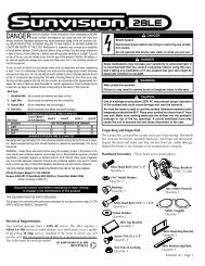
<strong>252</strong><br />
Depth: 50" Door Closed, 63” Door Open<br />
Width : 39.5"<br />
Height: 90"<br />
Shipping Weight: 1325 Lbs.<br />
No. of Lamps : 52<br />
Electrical : 39 AMPS @ 225 Volts, Three Phase or 63 Amps @ 225 Volts, Single Phase<br />
Circuit Requirements: 120/225V 3 Phase 50 Amp or 120/225V Single Phase 80 Amp<br />
DANGER - ULTRAVIOLET RADIATION. FOLLOW INSTRUCTIONS. AVOID OVEREXPOSURE. AS<br />
WITH NATURAL SUNLIGHT, OVEREXPOSURE CAN CAUSE EYE AND SKIN INJURY AND<br />
ALLERGIC REACTIONS. REPEATED EXPOSURE MAY CAUSE PREMATURE AGING OF THE SKIN<br />
AND SKIN CANCER. WEAR PROTECTIVE EYEWEAR; FAILURE TO MAY RESULT IN SEVERE<br />
BURNS OR LONG-TERM INJURY TO EYES.<br />
MEDICATIONS OR COSMETICS MAY INCREASE YOUR SENSITIVITY TO THE ULTRAVIOLET<br />
RADIATION. CONSULT PHYSICIAN BEFORE USING SUNLAMP IF YOU ARE USING MEDICATIONS<br />
OR HAVE A HISTORY OF SKIN PROBLEMS OR BELIEVE YOURSELF ESPECIALLY SENSITIVE<br />
TO SUNLIGHT. IF YOU DO NOT TAN IN THE SUN, YOU ARE UNLIKELY TO TAN FROM THE USE<br />
OF THIS PRODUCT.<br />
THIS UNIT UTILIZES UVA LAMPS. REPLACE ONLY WITH GENESIS 2000 SHRX FR<br />
78-T12-SHRX-2.<br />
TO OBTAIN THE RECOMMENDED EXPOSURE POSITION OF A MINIMUM USE DISTANCE OF 6"<br />
(152.4 MM) MEASURED WITH A STANDARD RULER, STAND UPRIGHT ON DECAL IN FLOOR OF<br />
UNIT. THE USE OF ANY OTHER POSITION MAY RESULT IN OVEREXPOSURE.<br />
SKIN TYPE<br />
II - FAIR<br />
III - AVERAGE<br />
IV - BROWN<br />
V - DARK BROWN<br />
WEEK 1<br />
1 ST-3RD<br />
TREATMENTS<br />
2 MIN.<br />
2 MIN.<br />
2 MIN.<br />
2 MIN.<br />
MAXIMUM EXPOSURE TIME IS 12 MINUTES.<br />
Specifications<br />
Recommended Exposure Schedule<br />
WEEK 2<br />
4TH-6TH<br />
TREATMENTS<br />
5 MIN.<br />
5 MIN.<br />
7 MIN.<br />
7 MIN.<br />
TANNING CAN BEGIN ON A REGULAR BASIS. AN APPEARANCE OF TANNING NORMALLY<br />
APPEARS AFTER A FEW EXPOSURES AND MAXIMIZES AFTER FOUR (4) WEEKS OF<br />
EXPOSURE FOLLOWING THE RECOMMENDED SCHEDULE FOR YOUR SKIN TYPE.<br />
USE PROTECTIVE EYEWEAR, SUPER SUNNIES, WHENEVER THE EQUIPMENT IS ENERGIZED.<br />
READ THE INSTRUCTION BOOKLET BEFORE USING THIS UNIT.<br />
INSTRUCTIONS ACCOMPANYING THIS PRODUCT SHOULD ALWAYS BE FOLLOWED TO AVOID<br />
OR MINIMIZE POTENTIAL INJURY.<br />
“THIS PRODUCT IS IN CONFORMITY WITH PERFORMANCE STANDARDS FOR SUNLAMP PRODUCTS UNDER 21 CFR PART 1040.”<br />
2<br />
WEEK 3<br />
7TH-10TH<br />
TREATMENTS<br />
8 MIN.<br />
8 MIN.<br />
10 MIN.<br />
10 MIN.<br />
WEEK 4<br />
11TH-15TH<br />
TREATMENTS<br />
10 MIN.<br />
10 MIN.<br />
12 MIN.<br />
12 MIN.<br />
WEEKLY<br />
SUBSEQUENT<br />
TREATMENTS<br />
12 MIN.<br />
12 MIN.<br />
12 MIN.<br />
12 MIN.
Warnings and Cautions<br />
Certain drugs - particularly those that<br />
produce photosensitivity - may cause<br />
individuals under the influence of this type drug<br />
to experience adverse effects and those people<br />
should avoid exposure to UV sources of all<br />
kinds. Doctors will advise persons taking these<br />
drugs to possible adverse effects.<br />
Mandatory Reading<br />
Always read and follow all instructions for proper usage prior to using any tanning system.<br />
Remember:<br />
1. Follow the exposure schedule in accordance with your skin type. Failure to do so may result<br />
in overexposure.<br />
2. A tanning system is not a toy. You cannot vary the strength of the lamps in your unit.<br />
Should you have any questions regarding the proper use of your tanning system, contact Sun<br />
Ergoline at:<br />
1-800-445-0624<br />
8:00 a.m. To 5:00 p.m. (CST)<br />
3<br />
It is recommended that only one person<br />
at a time should use the tanning system while<br />
in use, and advises using protective eyewear<br />
while taking a tanning session. One pair of<br />
goggles is provided with each sunbed sold.<br />
WARNING<br />
If you have been diagnosed by a physician as being allergic to the sun or are currently taking<br />
photosensitive medications, consult your physician before using the tanning unit.<br />
Occasionally, persons using the tanning<br />
system will experience a slight reddening of<br />
the skin - usually in small patches - after the<br />
second or third session. This redness is often<br />
accompanied by an itching sensation. This<br />
may be nothing more than a heat “rash” caused<br />
by heat from the lamps within the system.<br />
It should go away within approximately<br />
24 hours and should not reappear. This rashing<br />
can be lessened or prevented by applying<br />
moisturizer lotion to the affected area after the<br />
tanning session is completed.<br />
CAUTION<br />
While there is no immediate clinical evidence regarding UVA exposure and its effects upon<br />
EXPECTANT MOTHERS, it is strongly advised that expectant mothers be discouraged from using the<br />
tanning unit.
Care and Cleaning of Your <strong>Tan</strong>ning Unit<br />
After each session is completed, spray the<br />
acrylic surface with specially formulated UVT<br />
(ultraviolet transmitting) acrylic cleaner. Wipe<br />
the surface of the acrylic with a clean cloth.<br />
The acrylic should never be wiped with a dry<br />
4<br />
cloth because this will generate a slight static<br />
charge which will attract dust. A mild liquid<br />
detergent and water solution can be used<br />
temporarily in place of Acrylic Cleaner.<br />
For maximum efficiency of your tanning unit, periodic cleaning of lamps, reflectors and the inside<br />
of the acrylics is required. Refer to relamping instructions for acrylic removal.<br />
CAUTION: Do not use excessive amounts of water, any abrasive cleaners, or any spray cleaners<br />
that carry label warnings regarding reactions to contact with skin!<br />
1.<br />
2.<br />
3.<br />
4.<br />
5.<br />
6.<br />
7.<br />
DO NOT USE ALCOHOL OR AMMONIA<br />
Electrical Safety:<br />
The tanning unit should be disconnected from the power supply before cleaning of<br />
disinfecting the inside of the acrylic. Avoid water or solution entering the lamp compartment.<br />
Disconnect unit from power.<br />
Relamping Instructions<br />
To remove acrylic from Panel D (Door Panel), locate the six (6) 1/4 turn fasteners on the acrylic retainer<br />
strip on the left side of the panel. Using a flat head screwdriver, turn each fastener a 1/4 turn counter<br />
clockwise. You should hear a snap to release the strip. Repeat procedure on the remaining fasteners on<br />
the retainer strip.<br />
Lift edge of the acrylic approximately two (2) inches and slide acrylic to the left to remove.<br />
Twist lamp 1/4 turn to disengage lamp from lampholder. Remove lamp. Repeat procedure for the<br />
remaining twelve lamps in Panel D.<br />
Relamp, clean and replace acrylic sheet. To install acrylic sheet, slide the entire length of the right edge<br />
of the acrylic into the groove between the right rail and the acrylic the acrylic retainer strip. Flush the<br />
acrylic with the groove in the rail, and secure with the left acrylic retainer strip. To attach the acrylic<br />
retainer strip, align all six holes in the strip with the six holes in the left rail. Secure strip using a flathead<br />
screwdriver. Turn each fastener clockwise 1/4 turn. You should hear the fastener snap to secure the strip.<br />
Proceed to Panel C (next panel clockwise) and repeat procedures 2 through 5.<br />
Upon completion of all the panels, reconnect unit to power.<br />
CAUTION:<br />
Replacement lamps must comply with CFR21 1040.20<br />
A. Replace only with “Genesis 2000 SHRX FR78-T12 SHRX-2”<br />
B. When Ordering lamps, include model number and serial number.
Exposure Time and Frequencies<br />
Melanin - The brownish pigment produced<br />
by special cells in the base layer of your skin<br />
determines the individual’s tan. As the skin is<br />
exposed to the ultraviolet light, the melanin is<br />
activated and combines with protein cells that<br />
rise to the skin’s surface, thus producing a tan.<br />
5<br />
The amount of melanin in your body<br />
determines how quickly and dark you tan. The<br />
more melanin produced and exposure time an<br />
individual has, the faster and deeper the<br />
individual will tan. Do not tan more than once in<br />
a 24 hour period.<br />
NOTE<br />
The tan produced by the tanning unit is a deep, rich “cosmetic” tan. However, regardless of how<br />
dark an individual may tan on this system, it will not provide adequate protection against<br />
overexposure to natural sunlight or UVB tanning systems.<br />
SKIN TYPE II - This is the individual that<br />
usually burns easily and severely, tans minimally<br />
or lightly and peels.<br />
SKIN TYPE III - Often referred to as<br />
“AVERAGE” complexion, burns moderately and<br />
tans about average.<br />
SKIN TYPE<br />
II - FAIR<br />
III - AVERAGE<br />
IV - BROWN<br />
V - DARK BROWN<br />
Recommended Exposure Schedule<br />
WEEK 1<br />
1 ST-3RD<br />
TREATMENTS<br />
2 MIN.<br />
2 MIN.<br />
2 MIN.<br />
2 MIN.<br />
WEEK 2<br />
4TH-6TH<br />
TREATMENTS<br />
5 MIN.<br />
5 MIN.<br />
7 MIN.<br />
7 MIN.<br />
MAXIMUM EXPOSURE TIME IS 12 MINUTES.<br />
SKIN TYPE IV - This individual burns<br />
minimally, tans easily and above average with<br />
each exposure.<br />
SKIN TYPE V - This individual’s system rarely<br />
burn, tans easily and substantially.<br />
WEEK 3<br />
7TH-10TH<br />
TREATMENTS<br />
8 MIN.<br />
8 MIN.<br />
10 MIN.<br />
10 MIN.<br />
WEEK 4<br />
11TH-15TH<br />
TREATMENTS<br />
10 MIN.<br />
10 MIN.<br />
12 MIN.<br />
12 MIN.<br />
No two individual skin tones are the same. A tan to one person<br />
may be different to another and treatment length may vary.<br />
Note: Adequate ventilation of the room housing of<br />
the tanning unit is required for proper and<br />
comfortable operation. Air from the room is used<br />
to cool the unit, so be sure nothing obsstructs or<br />
blocks the airflow into or out of the fan and ventilation<br />
openings. Your tanning booth was designed to<br />
operate at an ambient room temperature, during<br />
unit operation of 75 degrees to 85 degrees.<br />
WEEKLY<br />
SUBSEQUENT<br />
TREATMENTS<br />
12 MIN.<br />
12 MIN.<br />
12 MIN.<br />
12 MIN.<br />
A poorly ventilated room may cause the unit to<br />
become hot and could cause discomfort to the user<br />
and damage the unit. Equally important many facial<br />
makeups have oil bases and should be removed<br />
prior to a session. It is recommended that, following<br />
a tanning session, a skin moisturizer be applied.<br />
This promotes a smoother, more even looking tan.
Step 1<br />
Remove floor assembly from carton marked “Top”<br />
The floor of your tanning unit consists of - two (2) parts<br />
A- Base -lower floor<br />
B. Floor -upper floor<br />
Step 2<br />
Position base in desired location. Align floor allowing<br />
a minimum of 63" from back of base to insure<br />
adequate distance to open door of unit properly.<br />
Also, allow a minimum of 18" around the<br />
parameter of the floor for ballast installation and<br />
access from the rear of the unit.<br />
(See Illustration 1)<br />
NOTE: Check to insure all panel attachment<br />
latches are fully open.<br />
(See Illustration 2)<br />
Assembly Instructions<br />
Step 3<br />
Remove panel B front box marked “PLB” and locate<br />
on base. Align slots in bottom plate of panel B with<br />
alignment pins in floor. Attach panel B to base with<br />
the two (2) attachment latches by placing the latch<br />
into slot in booth panel. Press downward on latch<br />
paddle, latch should snap into place securing panel<br />
B to base.<br />
(See Illustration 3)<br />
Step 4<br />
Remove panel A from box marked “PLA” and<br />
locate on base. Align slots in bottom plate of<br />
panel A with the alignment pins in floor. Align<br />
left side of panel A with right side of panel B,<br />
the side rails of both panels should nest together.<br />
Attached panel A to base with the two (2)<br />
attachment latches by placing the latch into<br />
slot in booth panel. Press downward on latch<br />
paddle, latch should snap into place securing<br />
bottom of panel A to base. Attach panel A to<br />
panel B with the upper panel latch located on<br />
the top of panel B by repeating the above l<br />
atching procedure.<br />
(See Illustration 4)<br />
6<br />
Illustration 1<br />
Illustration 4<br />
Illustration 2<br />
Illustration 3
Step 5<br />
Remove panel C from marked “PLC” and locate<br />
on base. Align slots in bottom plate of<br />
panel C with the alignment pins in floor.<br />
Align right side of panel C with left side of<br />
panel B, the side rails of both panels should<br />
nest together. Attach panel C to base with<br />
the two (2) attachment latches by placing<br />
the latch into slot in booth panel. Press<br />
downward on the latch paddle, latch should<br />
snap into place securing bottom of panel C<br />
to base. Attach panel C to panel B with the<br />
upper panel latch, located on the top of panel<br />
B by repeating the above latching procedure.<br />
(See Illustration 5)<br />
Step 6<br />
Remove Panel D from box marked “PLD” and<br />
stand panel upright into position. Place washer<br />
over both top and bottom hinge pins. Align<br />
hinge pins in door with hinges in Panel C, and<br />
allow hinge pins to drop into hinges. The door<br />
panel will re-hang on booth body.<br />
(See Illustration 6)<br />
Step 7<br />
Locate floor and place over base.<br />
Attach floor to base with safety rails.<br />
By placing safety rail on threaded studs<br />
protruding through floor. Tighten rails securely.<br />
(See Illustration 7 )<br />
Step 8<br />
Remove top fan panel from box marked “Top”.<br />
Place top fan panel on tanning unit. Attach<br />
top fan panel to tanning unit using the nine<br />
(9) provided 5/16" - 18 x 1 bolts.<br />
(See Illustration 8)<br />
Assembly Instructions<br />
Illustration 7<br />
7<br />
Illustration 6<br />
Illustration 5
Step 9<br />
Locate lamp harness and place on top.<br />
To connect lamp harness to panel A terminate<br />
harness to panel A cord 2 align plug and twist<br />
clock wise until locked. Repeat procedure for<br />
panel B cord 2, panel C cord 2 and door panel<br />
cord.<br />
(See Illustration 9)<br />
Step 10<br />
Locate panel A power cord 1 and connect with<br />
panel A cord 1. To terminate panel A cord 1 to<br />
power cord 1 align plug and twist clock wise until<br />
locked. Repeat procedure for panel B cord 1 and<br />
panel C cord 1.<br />
(See Illustration 9)<br />
Step 11<br />
Locate top fan wires and connect to fan power wires<br />
from Panel A to fan. Match connector to the corresponding<br />
color.<br />
(See Illustration 10)<br />
Step 12<br />
Illustration 9<br />
Remove plastic top cover from box and connenct the<br />
three (3) 4 conductor phone cables from Panel A<br />
to timer jack plate in plastic top cover. Secure top<br />
cover to top of unit using four (4) 1/4 - 20 X 3/4 bolts.<br />
(See Illustration 8)<br />
Step 13<br />
Remove one (1) ballast panel from box marked<br />
“ballast”. To install ballast panel slide tabs of<br />
ballast panel into slots at bottom of ballast<br />
access. To avoid later service problems please<br />
note that the interior harness is not trapped<br />
between ballast panel inner booth structure.<br />
Attach ballast panel to inner booth structure<br />
with two (2) of the provided # 6 x 3/8 philips<br />
screws tighten securely.<br />
(See Illustration 10)<br />
Step 14<br />
Connect ballast to lamps by terminating the MTE/LK<br />
male harness plug with the female ballast plug.<br />
Repeat procedure for remaining ballast panels.<br />
(Refer to Pages 25-27)<br />
Assembly Instructions<br />
8<br />
Illustration 8<br />
Illustration 10
Step 15<br />
Attach ballast access covers with #6 x 3/8 philips<br />
screws and snap caps.<br />
(See Illustration 11)<br />
Assembly Instructions<br />
Step 16<br />
There are two terminal blocks located on the ballast tray<br />
installed in each panel. Each panel has a relay with four<br />
power wires (2 Black & 2 Red) with quick-slide connectors<br />
that are to be connected to the mentioned terminal blocks<br />
at the time of installation. Install the wires on the terminal<br />
block as shown with the corresponding colors. If the<br />
wires from the relay are improperly installed on the wrong<br />
terminals, certain lamps in the tanning unit will not illuminate.<br />
(Refer to Schematic page 24, for more details.)<br />
Step 17<br />
Contact a local licensed electrician to connect electrical supply to unit. Your tanning booth requires a<br />
120V/225V three phase, 50 amp service or 120V/225V single phase 80 amp 4 wire service. Use of a voltage<br />
source below 215VAC or above 230VAC may prevent proper operation of the booth and could cause damage<br />
and void the warranty.<br />
NOTE: This unit is factory pre-wired for three phase operation. See page 31 for single phase<br />
conversion instructions and wire gage.<br />
9<br />
Illustration 11
Intellitan Plus by Sun Ergoline<br />
Operating Instructions<br />
To Set Time<br />
STEP 1:Press s on the button labeled time to reach desired setting in minutes.<br />
STEP 2:Press “Start/Stop” to begin operation. The session is counted down in minutes and seconds.<br />
NOTE: If a session delay is preprogrammed (P04), the display will begin to flash the session<br />
time. The display will continue to flash the session time for the duration of the session delay<br />
according to the programming or until the “Start/Stop” button is pressed. If the “Start/<br />
Stop” button is pressed before the session delay expires, the display will stop flashing and<br />
the session time will begin to count down. At one (1) minute, before the start of the tanning<br />
session, an audible beep will sound (if programmed in P02). At thirty (30) seconds, before the<br />
start of the tanning session, another audible beep will sound. At ten (10) seconds the audible<br />
beep will sound and continue once each second until tanning unit lights. Once the tanning<br />
unit has started, the session delay will not repeat on subsequent restarts.<br />
To Stop Unit<br />
STEP 1:Press “Start/Stop” anytime during a session. This will stop the countdown and hold time. To restart<br />
the unit simply press “Start/Stop” .<br />
To Clear Time<br />
STEP 1: Press “Reset” the timer clears to read 00:00<br />
NOTE: If the unit is counting down, the “Start/Stop” button must be pressed before resetting.<br />
10
To Change Parameters<br />
Timer Edit Procedure<br />
To enter the System’s data bank, monitor operations and verify the vital functions concerning your unit,<br />
use the following step-by-step instructions. Note: Each timer manufactured after 1995 displays the<br />
current software version on power up. These instructions are for level 23 and above of the Intellitan<br />
Plus timer.<br />
Enter Password Clearance<br />
1. Press (at the same time) then release s and t buttons; the display will change from 00:00 to 0000. If<br />
you cannot get the display to change to 0000, assure that you have disconnected the network cable(s)<br />
from the timer. If power to the tanning unit is not cycled on/off after disconnecting the network cable, you<br />
must wait for thirty seconds for the timer to award access to the above mentioned buttons.<br />
2. Press the “Reset” button once so that 0000 begins to flash.<br />
3. Use the s button to enter the appropriate password to perform the desired function. Password 0010<br />
(ten) must be entered to view parameters, and 0102 (one hundred and two) to edit parameters. After<br />
entering the password press the “Reset” button. The display will stop flashing and 0001 (level one) or<br />
0002 (level two) will appear in the display.<br />
4. Press the “Start/Stop” button to enter parameter mode, followed by s the button to reach the desired<br />
parameter. If you go past a parameter you may press the “Reset” to return to the desired parameter.<br />
Each time the s or t button is pressed the timer will display PXX (XX represents numbers) representing<br />
the parameter reached and the display will change showing the value of the parameter.<br />
5. If you are using the second level password, press the “Reset” button to edit the parameter (once the<br />
“Reset” button is pressed the display will begin to flash). Use either the s or t button to set the<br />
appropriate value for the parameter, then press “Reset” to exit the parameter.<br />
6. Press the appropriate s or t button to reach another parameter. You May press the “Start/Stop”<br />
button to exit the edit parameter mode.<br />
11
P02 Parameter 2 is the chime mechanism that provides an audible ‘beep’ sound when the keys are depressed<br />
and to indicate the various operations occurring. The audible beep can be turned on or turned off. The unit<br />
comes with the chime mechanism turned on to provide an audible beep. When parameter 02 is<br />
shown, the display will read 0001. To maintain the chime mechanism, press the s now and go to P03. To<br />
silence it, do the following:<br />
To Change Parameter 2, Alarm On/Off<br />
Press “Reset” once then release it. The display will begin to flash. Press s and hold it down, scrolling<br />
down to 0000. Now “Reset” press once again. The chime is now deactivated. To reactivate the chime,<br />
change parameter 02 back to 0001 using the same instructions provided above.<br />
Now press s to reach Parameter 3 (P03), the Fan Delay or Post Session Cooling<br />
P03 Parameter 3 is the fan delay. The fan delay maintains proper cooling of the tanning unit by continuing to<br />
provide power to the cooling fans for a programmable amount of time after the tanning session has<br />
completed. The unit comes with the fan delay preprogrammed at one (1) minute. Certain salon<br />
conditions may warrant a higher fan delay to maintain proper cooling. The fan delay cannot be turned off.<br />
When parameter 03 is shown, the display will read 1.0 representing one minute. To change the fan delay,<br />
do the following:<br />
To Change Parameter 3, Fan Delay<br />
Parameter Detail<br />
Press “Reset” once then release it, the display will begin to flash. Press either s or t to reach<br />
desired setting. Time is displayed from 1.0 to 5.0, with decimal representing tenths of a minute. For<br />
Example: 1.5 equals 1 minute, 30 seconds. After setting the fan delay press “Reset” once then<br />
release it. The fan delay is now set.<br />
NOTE: Fan Delay<br />
The duration of the fan delay is not displayed on the timer while the fan delay is counting down. Time is,<br />
however, displayed on the CCS-1 or the other control device during the fan delay to indicate how long the<br />
fan delay has remaining. After a tanning session has expired, the ( _ _:_ _ ) will flash and the numeric<br />
digits display will blink (off). If the Clean Room feature is on then along with the flashing colon (:) dashes<br />
will appear in the display ( - - : - - ). When displayed on the CCS-1 or other control device the duration of<br />
the fan delay counts down in three second decrements.<br />
Note: When the Intellitan Plus timer is on a network no new time can be placed on the timer until after the<br />
fan delay has expired. The fan delay cannot be turned off.<br />
Now press s to reach Parameter 4 (P04), the Session Delay function.<br />
12
P04 Parameter 4 is the session delay. The session delay allows a programmable amount of time at the<br />
beginning of a session to get ready for the tanning session. The tanning session time shown on the timer<br />
flashes during the session delay. The unit comes with no session delay preprogrammed.<br />
To Change Parameter 4, Session Delay<br />
When parameter 04 is shown, the display will read 0.0 for no session delay. To change the session delay,<br />
do the following:<br />
Press “Reset” once then release it, the display will begin to flash. Now press s or t to reach the<br />
desired setting. Time is displayed from 0.0 to 10.0, with the decimal representing tenths of a minute.<br />
Example: 2.5 equals 2 minutes, 30 seconds. After reaching the desired setting, press “Reset” once<br />
and release it. Session delay is now set.<br />
Now press s to reach Parameter 5 (P05), the Station Address function.<br />
P05 Parameter 5 is the station address. The station address allows the tanning unit to be identified for<br />
interface with the CCS series controllers, the Intellitan Single Station Console, or the Intellitan Protocol<br />
Interface (IPI) for your computer system. The unit comes with a station address of zero (0)<br />
preprogrammed, if you have multiple units each must be uniquely addressed.<br />
To Change Parameter 5, Station Address<br />
Parameter Detail<br />
When parameter 05 is shown, the display will read 0000 for station address zero. To change the station<br />
address, do the following:<br />
Press “Reset” once and release it, the display will begin to flash. Now press s or t to reach desired<br />
address setting. Once the desired setting is reached press “Reset” once and release it. The station<br />
address is now set.<br />
Now press s to reach Parameter 6 (P06), the Lamp-Hour Accumulation on Current Lamp Bank<br />
function.<br />
P06 Parameter 6 is the lamp hour accumulation counter. The lamp hour accumulation counter keeps track of<br />
the number of hours on the current lamp bank. This is a resettable parameter that should be reset to 0<br />
when the lamps are changed. When current lamp hour accumulation reaches 0000, a beep will chime<br />
each time the unit is turned on, indicating that a lamp change is necessary. Chime will not sound if it has<br />
been turned off through parameter 2. Parameter 6 is only editable at password level 1.<br />
When parameter 06 is shown, the display will read from 0000 to 9999. To clear the lamp hour accumulator,<br />
do the following:<br />
To Clear Parameter 6, Lamp Hour Accumulation<br />
Press “Reset” once and release, the display will begin to flash. Now press and hold s until 0000 is<br />
displayed. When the display reads 0000 press “Reset” once and release. Lamp hour accumulation is<br />
now cleared.<br />
Now press s once and release it to reach Parameter 7 (P07), to measure A/C Voltage Phase A.<br />
13
Parameter Detail<br />
P07 Parameter 7 is the measurement of the A/C voltage on phase A. The A/C voltage will be immediately<br />
displayed from 0000 to 0200 volts, with 0120 as the nominal reading.<br />
Now press s once and release it to reach Parameter 8 (P08), to measure A/C Voltage Phase B.<br />
P08 Parameter 8 is the measurement of the A/C voltage on phase B. The A/C voltage will be immediately<br />
displayed from 0000 to 0200 volts, with 0120 as the nominal reading.<br />
Now press s and release it to reach Parameter 9 (P09), to measure the Average Voltage on Phase<br />
A.<br />
P09 Parameter 9 is the measurement of average A/C voltage on Phase A for the previous session, or current<br />
session if unit is energized. The reading is immediately displayed.<br />
Now press s and release it to reach Parameter 10 (P10) for measuring the average voltage on Phase<br />
B.<br />
P10 Parameter 10 is the measurement of average A/C voltage on Phase B for the previous session, or current<br />
session if the unit is energized. The reading is immediately displayed.<br />
Now press s and release it to reach Parameter 11 (P11), the measurement of the unit’s Operating<br />
Temperature.<br />
P11 Parameter 11 is the measurement of the units internal operating temperature. The reading is immediately<br />
displayed. Measurement is in Fahrenheit.<br />
Now press s and release it to reach Parameter 12 (P12), the measurement of the unit’s Ambient<br />
Temperature.<br />
P12 Parameter 12 is the measurement of the units ambient or room temperature. The reading is immediately<br />
displayed. Measurement is in Fahrenheit.<br />
Now press s once and release it to reach Parameter 13 (P13), the Measurement of the units Average<br />
Operating Temperature<br />
P13 Parameter 13 is the measurement of the units average operating temperature during the previous session<br />
or current session if the unit is energized. The reading is immediately displayed. Measurement is in<br />
Fahrenheit.<br />
Now press s once and release it to reach Parameter 14 (P14), the measurement of the Average<br />
Ambient Temperature.<br />
14
Parameter Detail<br />
P14 Parameter 14 is the measurement of the average ambient or room temperature during a previous session<br />
or current session if the unit is energized. The reading is immediately displayed. Measurement is in<br />
Fahrenheit.<br />
Now press s once and release it to reach Parameter 15 (P15), the Clean Room feature.<br />
P15 Parameter 15 is the clean room feature. When on, the clean room feature will show all dashes (- - - -) on<br />
the timer display at the end of each tanning session to show that the tanning unit needs to be cleaned. In<br />
network mode, no new time can be placed on the timer when the clean room indicator is displayed.<br />
To reset the clean room feature from the room, indicating that the room has been cleaned, press the<br />
“Reset” button twice in rapid succession. When the Clean Room feature is reset, the room timer will<br />
display 00:00. The unit comes with the clean room feature off.<br />
To Change Parameter 15, Clean Room Feature<br />
Press “Reset” once then release it, the display will begin to flash. Now press s once to display 0001,<br />
then press “Reset” once and release it. The Clean Room Feature is now enabled. To disable the Clean<br />
Room Feature simply change parameter 15 back to 00:00.<br />
Now press s once and release it to reach Parameter 16 (P16), the Econometer.<br />
P16 Parameter 16 is the Econometer. The Econometer measures the electrical cost to power unit for previous<br />
session or the current session if the tanning unit is active. The cost displayed is derived from the session<br />
cost per minute entered in P17. The reading is displayed immediately. Measurement is in cents and<br />
tenths of a cent. This function is read only and can not be changed. Example - A reading of 10.7 would<br />
equal 10.7 cents.<br />
Now press s once and release it to reach Parameter 17 (P17), Cost Per Session.<br />
P17 Parameter 17 is the session cost per minute. This figure is automatically entered into the tanning units<br />
data bank in accordance with the National Average of 7.54 per kilowatt hour. The formula used is Unit<br />
KwH Draw X National Average / 60 minutes = cost per minute. (Example 232G 3.1 x 7.5 / 60 = 0.388<br />
rounded up to .4 cents per minute.)<br />
To Change Parameter 17, Cost Per Minute<br />
Press “Reset” once then release it, the display will begin to flash. Now press s or t until the desired<br />
cost per minute is displayed. Measurement in cents and tenths of a cent. (Example: A reading of .4<br />
would equal four tenths of one cent.) Once the desired reading is displayed press once and release it.<br />
The Cost Per Minute is now set.<br />
Now press s once and release it to reach Parameter 18 (P18), the Session Counter.<br />
15
Parameter Detail<br />
P18 Parameter 18 is the Session Counter. The session counter displays the total number of times a session<br />
has been started since first day of operation. The session counter counts from 0000 to 9999 then rolls<br />
over. The session counter cannot be adjusted or reset.<br />
Now press s once and release it to reach Parameter 19 (P19), Total Hour Accumulation.<br />
P19 Parameter 19 is the total hour accumulator. This accumulator displays the total number hours on the unit<br />
since first day of operation. The accumulator counts from 0000 to 9999 then rolls over. The total hour<br />
accumulator cannot be adjusted or reset.<br />
Now press s once and release it to reach Parameter 24 (P24), Continuous Countdown Mode.<br />
Note: Parameters 20-23 are reserved for factory use.<br />
P24 Parameter 24 is the continuous countdown mode toggle. The default is 0 for disabled. The continuous<br />
countdown mode allows the salon owner to maintain a tighter schedule by disabling the pause function of<br />
the timer thus allowing the tanning time to continue to count down even if the lamps are turned off by<br />
pressing the start/stop key. This feature is only available with software level 16 or higher.<br />
To Change Parameter 24, Continuous Countdown Mode<br />
Press “Reset” once then release it, the display will begin to flash. Now press s until 0001 is displayed,<br />
press “Reset” once and release it. Next cycle the power to the timer and tanning unit off and back on. The<br />
Continuous Countdown Mode is now enabled. To disable this function change parameter 24 back to 0000.<br />
Now press s once and release it to reach Parameter 25 (P25), Keylock Configuration.<br />
P25 Parameter 25 is the keylock configuration option. The default is 3 for 30 seconds. The keylock configuration<br />
option allows the salon owner to maintain a higher sense of security by locking out the front rail keys in<br />
several specified intervals while the timer is connected to a network. This feature is only available with<br />
software level 16 or higher. The keylock intervals are:<br />
0 - Lock keys and release only when power cycled.<br />
1 - Lock keys and release only when parameter is changed to an option other than 01.<br />
2 - Lock keys and release only after the network cable has been removed for 2 minutes.<br />
3 - Lock keys and release only after the network cable has been removed for 30 seconds.<br />
WARNING: If you set parameter 25 to 01 (Lock until parameter changed) you will be unable to change this<br />
parameter or unlock the front rail keys without the use of a CCS-1 or other control device. The Intellitan<br />
Protocol Interface (IPI) does not edit this or any other parameter.<br />
To Change Parameter 25, Keylock Configuration<br />
Press “Reset” once then release it, the display will begin to flash. Now press s until the desired option<br />
0,1,2,3 is displayed, press “Reset” once and release it. Next cycle the power to the timer and tanning<br />
unit off and back on. The Keylock Configuration is now saved.<br />
Now press s once and release it to reach Parameter 26 (P26), TPI Interface Enable.<br />
16
P26 Parameter 26 is the Third Party Interface (TPI) Mode toggle. The default is 0 for disabled. The Intellitan<br />
Plus timer has a TPI jack built in to the timer itself. This jack replaces the need for a second or additional<br />
interface when using other timer systems. The TPI jack is located next to the two network jacks on the top<br />
of the tanning unit (under the hinge cover). It is the larger of the three jacks and comes with a unused<br />
modular plug in the jack. When using the Intellitan Plus timer in TPI mode the Intellitan Plus looks for<br />
control voltage (5-30v) on the outside two wires of the modular cable plugged into the TPI port. When this<br />
voltage is seen, the maximum tanning time is sent to the timer and the tanning unit is started. Any<br />
session delay should be programmed on the third party timer and the Intellitan session delay should be<br />
set to 0. The front rail keys are locked in TPI mode. This feature is only available with software level<br />
16 or higher.<br />
To Change Parameter 26, TPI Mode<br />
Parameter Detail<br />
Press “Reset” once then release it, the display will begin to flash. Now press s until 0001 is displayed,<br />
press “Reset” once and release it. Next cycle the power to the timer and tanning unit off and back on. The<br />
TPI Mode is now enabled. To disable this function change parameter 26 back to 0000.<br />
Now press s once and release it to reach Parameter 27 (P27), Timer Protocol Option.<br />
P27 Parameter 27 is the Timer Protocol Option. The default is 0001 for Intellitan Protocol. The timer protocol<br />
option allows the salon owner to change timer network protocols from the Intellitan Network to the T-Max1 protocol for use with the Applied Digital T-Max Manager. For additional information please consult the T-<br />
Max documentation. This feature is only available with software level 16 or higher.<br />
To Change Parameter 27, Timer Protocol Option<br />
Press “Reset” once then release it, the display will begin to flash. Now press s until 0001 is displayed,<br />
press “Reset” once and release it. Next cycle the power to the timer and tanning unit off and back on.<br />
The T-Max Protocol is now on. To turn off this function change parameter 27 back to 0000 using the<br />
parameter edit instructions in the T-Max documentation. You can not use a CCS-1 or IPI with a timer<br />
using T-Max Protocol.<br />
Now press s once and release it to reach Parameter 28 (P28), Total Operating Cost.<br />
P28 Parameter 28 is the Total Operating Cost Accumulator. This parameter tracks total operating costs of the<br />
tanning unit based upon parameter 17, session cost per minute. This parameter is displayed in dollars and<br />
tenths and rolls over at $999.9. The Total Operating Cost Accumulator can be reset to 0 at anytime in<br />
order to track or determine daily, weekly, monthly, quarterly, or annual operating costs.<br />
To Change Parameter 28, Total Operating Cost<br />
Press “Reset” once then release it, the display will begin to flash. Now press s until 0000 is displayed,<br />
press “Reset” once and release it. The Total Operating Cost is now reset to 0 and will begin accumulating<br />
at the next session.<br />
17
Wiring Diagram<br />
18
Relay Diagram<br />
19
Relay Panel A<br />
20
Relay Panel B<br />
21
Relay Panel C<br />
22
Relay Terminal Block<br />
23
Ballast Tray Connection<br />
24
Ballast Tray A1, B1 and C1<br />
25
Ballast Tray A2 and C2<br />
26
Ballast Tray B2<br />
27
<strong>Bed</strong> Cords<br />
28
Door Harness<br />
29
3 Phase Connection<br />
30
Single Phase Connection<br />
NOTE: This unit is factory pre-wired for three phase operation. During conversion to<br />
single phase operation you must replace the incoming power wires to 4 gage THHN 90<br />
degrees or equivalent.<br />
31
General Troubleshooting Guide<br />
The following troubleshooting information is divided into two sections. Section A contains items in which the<br />
owner may check without the aid of a service person. Section B contains items which must be performed by<br />
QUALIFIED SERVICE PERSONNEL ONLY. If you have any questions other than the ones listed in your<br />
troubleshooting guide, contact your dealer or distributor NOTE: All tanning units are not the same, therefore<br />
some of the causes may not apply to your unit.)<br />
1. <strong>Tan</strong>ning unit does not operate.<br />
CAUSE<br />
1. No power to unit.<br />
2. Timer is not activated.<br />
General Troubleshooting (Section A)<br />
Note: If there is power to the unit but the display on the timer is not lighting, you may need to replace<br />
the timer. Contact Sun Ergoline or your local representative for information.<br />
2. Lamps will not light or lamps flicker.<br />
CAUSE<br />
1. Lamp not seated properly in<br />
lampholder.<br />
2. Faulty lamp.<br />
General Troubleshooting (Section B)<br />
32<br />
SOLUTION<br />
1. Remove lamp, inspect contact on lamp,<br />
and reinstall lamp securely into<br />
lampholder.<br />
2. Replace lamp. (Refer to Instruction<br />
Manual for correct lamp.)<br />
All services in the following section are to be completed by a Qualified Service Technician. This section is to<br />
aid in isolating and correcting problems which may occur and is not intended for the use by the owner. Refer<br />
to the assembly instructions included with each unit for reference in disassembling and wiring the tanning<br />
unit. Disconnect all power to the unit before servicing. Use only factory authorized components for replacement<br />
parts.<br />
1. <strong>Tan</strong>ning unit does not operate.<br />
CAUSE<br />
1. Incorrect connection of incoming<br />
power.<br />
2. Faulty Timer<br />
3. Faulty relay in unit.<br />
4. Poor wiring connections.<br />
2. Lamps will not light.<br />
CAUSE<br />
1. Poor wiring crimp at the lampholder.<br />
2. Faulty or damaged lampholder.<br />
3. Incoming power to the unit is incorrect.<br />
4. Faulty Ballast<br />
5. Loose power wire to ballast.<br />
SOLUTION<br />
1. Check circuit breaker servicing unit.<br />
2. Press up button, then start button.<br />
SOLUTION<br />
1. Check Electrical connection on wiring<br />
diagram and correct as necessary.<br />
2. Replace<br />
3. Replace<br />
4. Check wiring circuit against<br />
appropriate diagram and correct as<br />
required.<br />
SOLUTION<br />
1. Check for loose wire and repair.<br />
2. Replace lampholder<br />
3. Check incoming voltage and correct to<br />
requirements.<br />
4. Locate and replace<br />
5. Locate loose wire and repair.
Important Note<br />
PREVENTIVE MAINTENANCE SCHEDULE<br />
Your Genesis <strong>Tan</strong>ning System consists of many movable parts that may require periodic adjustments<br />
and/or replacement.<br />
It is imperative that you, the owner and/or operator, check all components for any signs of wear<br />
which may occur through normal use.<br />
The frequency of your preventive maintenance schedules should be determined according to<br />
equipment usage. The minimum of a monthly inspection of all components is a good guideline,<br />
however, actual frequency and thoroughness of inspections is your responsibility.<br />
Should you require any assistance or need additional information, please call our Service<br />
Department at 1-800-445-0624, Monday through Friday 8:00 a.m. -5:00 p.m. CST<br />
REPAIRS-SERVICE-REPLACEMENT<br />
PARTS AND LAMPS-EYE PROTECTION<br />
If you are in need of any of the above mentioned products or services, you should contact the<br />
dealer/distributor through whom you purchased your unit. In the event that you are unable to do so,<br />
please call our Service Department for assistance at: 1-800-445-0624.<br />
NOTE: All repairs and replacement components including, but not limited to, protective eyewear,<br />
lamps, timers, acrylic and reflectors must be in compliance with CFR 21 1040.20.<br />
33
SUN Ergoline, Inc.<br />
Limited Warranty<br />
Sun Ergoline warrants its products to be free from defects in materials and workmanship under intended<br />
normal use as described in the unit’s Operation and Instruction Manual, for a period of one (1) year from date<br />
of sale.<br />
This Limited Warranty applies only to the original purchaser of the equipment through Sun Ergoline or its<br />
authorized dealer or distributor, and is not transferable.<br />
Sun Ergoline’s obligations under this warranty are limited to repair or replacement of any defective part<br />
without charge for that part to the original purchaser, with the following exceptions:<br />
A. Fluorescent lamps are warranted against defects for a period of thirty (30) days from date of sale.<br />
B. Only parts obtained through Sun Ergoline, its authorized dealers or distributors may be used.<br />
Transportation costs for parts shipped to the consumer and the return of defective parts to Sun<br />
Ergoline are not included.<br />
C. Labor will be furnished without charge for ninety (90) days from date of purchase only. All labor<br />
and related charges must be authorized by Sun Ergoline prior to start of repairs, and must coincide<br />
with Sun Ergoline established rates and time allotment policy.<br />
D. Acrylic: Refer to Manufacturer’s Acrylic Warranty Policy.<br />
It is imperative that the original customer completes and returns the enclosed warranty card within 10 days<br />
after purchase to insure valid registration and coverage for potential claims.<br />
If the warranty card is not registered, proof of purchase from Sun Ergoline or its authorized dealer or<br />
distributor will be required prior to any consideration on warranty claims. This could result in service delays.<br />
This warranty is extended to the individual or legal entity, whose name appears on the warranty registration<br />
card filed with Sun Ergoline, or whose name appears on the original sale document and may not be transferred<br />
to any other individual or legal entity.<br />
This warranty does not apply to any failure of the product, or any parts of the product due to alterations,<br />
modifications, misuse, abuse, accident, improper maintenance, improper installation, acts of God or if the<br />
serial number on the product has been removed, altered or defaced. Adequate packaging must be used for<br />
returned goods to prevent freight damage.<br />
THERE ARE NO WARRANTIES WHICH EXTEND BEYOND THE DESCRIPTION ON THE FACE HEREOF.<br />
THERE IS NO EXPRESS OR IMPLIED WARRANTY OF FITNESS OR MERCHANTABILITY.<br />
THE REMEDIES PROVIDED IN THIS LIMITED WARRANTY ARE THE EXCLUSIVE REMEDIES<br />
PROVIDED TO THE PURCHASER BY SUN ERGOLINE AND ARE PROVIDED IN SUBSTITUTION OF ALL<br />
OTHER REMEDIES - CONSEQUENTIAL AND INCIDENTAL DAMAGES ARE EXCLUDED.<br />
No person, firm or corporation is authorized to obligate Sun Ergoline for any liability in connection with the<br />
sale or use of these goods.<br />
34
Limited Acrylic Warranty<br />
Sun Ergoline warrants its acrylic sheets to be free from defects in material and workmanship,<br />
under intended normal use, for a period of one (1) year from date of sale of the tanning bed. Due to<br />
the tanning lotions, cosmetics, disinfectant and improper cleaners used on tanning surfaces that<br />
cannot be controlled by Sun Ergoline after the first thirty (30) days of warranty period. Acrylic will<br />
be subject to a prorated cost to the consumer on breakage.<br />
Sun Ergoline’s obligations do not include transportation charges on replacement acrylic.<br />
Sun Ergoline assumes no liability for the cost of removing defective sheets or installing<br />
replacement sheets, nor for damage to persons or property.<br />
To make a claim, contact an authorized dealer or distributor of Sun Ergoline or Sun Ergoline<br />
Service Department with the model number, the serial number, and the date of purchase of the bed<br />
in which the acrylic will be used.<br />
THERE ARE NO WARRANTIES WHICH EXTEND BEYOND THE DESCRIPTION ON THE FACE<br />
HEREOF. THERE IS NO EXPRESS OR IMPLIED WARRANTY OF FITNESS OR MERCHANTABILITY.<br />
THE REMEDIES PROVIDED IN THIS LIMITED WARRANTY ARE THE EXCLUSIVE REMEDIES<br />
PROVIDED TO THE PURCHASER BY SUN ERGOLINE AND ARE PROVIDED IN SUBSTITUTION<br />
OF ALL OTHER REMEDIES - CONSEQUENTIAL AND INCIDENTAL DAMAGES ARE EXCLUDED.<br />
Sun Ergoline<br />
P.O. Box 2026<br />
Jonesboro, Arkansas 72402<br />
1-800-445-0624<br />
870-935-1130 (in Arkansas)<br />
35
1. When to file a Warranty Claim:<br />
Warranty Claims<br />
Policy & Procedures<br />
In the event that your tanning system is not functioning properly under intended normal use as<br />
described in the unit’s Operation and Instruction Manual, you may then have established cause to<br />
file a Warranty Claim.<br />
NOTE: Both the tanning system and legal registered owner must meet the criteria established under<br />
Sun Ergoline Limited Warranty as described in this manual before any Warranty Claim will be<br />
considered.<br />
2. Where to call to place a Warranty Claim:<br />
Sun Ergoline is supported nationwide by an extensive dealer/distributor network through whom<br />
the majority of our units are sold. These dealers/distributors are required by contract to stock sufficient<br />
parts to meet the various warranty and nonwarranty needs of their customers.<br />
Therefore, in order for you to properly file a Warranty Claim, you must locate the name and phone<br />
number of the dealer/distributor through whom you purchased your unit. Normally this information can<br />
be easily located either on your paid invoice or other proof of purchase documentation that you<br />
received when taking delivery of the unit.<br />
Next, notify the dealer/distributor of the serial number, model number and date unit was purchased.<br />
This will initiate the Warranty Claim process.<br />
Upon determination of the problem, your dealer/distributor can then supply you with the part(s) and<br />
proper instructions to return your unit to working order.<br />
Each dealer/distributor has their own internal procedure for handling Warranty Claims and credits.<br />
NOTE: Sun Ergoline, the manufacturer, does not involve itself in the direct handling of<br />
a Warranty Claim except where mitigating circumstances apply and where required by law.<br />
36
<strong>Parts</strong> Warranty Claim/Credit Review<br />
1. Customer calls Sun Ergoline and notifies the Service Department of problem.<br />
2. Sun Ergoline Service Department determines course of action.<br />
3. Sun Ergoline ships part and R.A.I. to customer freight collect and bills customer on net 30 basis for part<br />
only.<br />
4. Customer, within 15 days of receiving new part, returns defective part to Sun Ergoline along with R.A.I.<br />
5. Upon receipt of defective part and R.A.I., Sun Ergoline issues customer a credit invoice which offsets<br />
original bill. Customer’s account is returned to zero balance concerning this claim.<br />
NOTE: If part returned to Sun Ergoline proves to be operational and not defective, or if product code numbers<br />
on part do not correspond with individual unit date on file with Sun Ergoline, then a 30% restocking fee will be<br />
charged in addition to the retail purchase price of part.<br />
Acknowledgment of the Agreement is not required for acceptance of the foregoing stipulations.<br />
LABOR WARRANTY CLAIM/CREDIT PROCEDURES<br />
Sun Ergoline furnishes labor without charge for a period of 90 days from date of purchase. All labor and related<br />
charges must be authorized by Sun Ergoline prior to start or repairs, and must coincide with Sun Ergoline<br />
established rates and time allotment policy.<br />
Please contact our Service Department for authorization and billing procedures.<br />
37
Notice: Any misuse, abuse, modification, alteration, improper maintenance, improper<br />
installation, etc. of this product or its intended use will subject said party to direct<br />
responsibility and liabilities for any and all consequences resulting from such action.<br />
Furthermore, such actions will void all warranties and may relieve Sun Ergoline of any<br />
liabilities relating to said product.<br />
<strong>252</strong>2002