Sun|Dash 332 Pro 1 15 Minute - Tanning Bed Parts
Sun|Dash 332 Pro 1 15 Minute - Tanning Bed Parts
Sun|Dash 332 Pro 1 15 Minute - Tanning Bed Parts

Create successful ePaper yourself
Turn your PDF publications into a flip-book with our unique Google optimized e-Paper software.
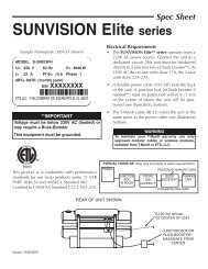
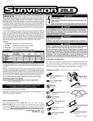
Specifications<br />
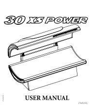
Length: 85”<br />
Width: 41”<br />
Height: 39.8” - 49.6”<br />
Number of Lamps: 32 Low Presure<br />
Electrical: 120/208VAC and 120/240VAC<br />
Circuit Required: 20 Amp Breaker<br />
DANGER - ULTRAVIOLET RADIATION. FOLLOW INSTRUCTIONS. AVOID OVEREXPOSURE. AS<br />
WITH NATURAL SUNLIGHT, OVEREXPOSURE CAN CAUSE EYE AND SKIN INJURY AND<br />
ALLERGIC REACTIONS. REPEATED EXPOSURE MAY CAUSE PREMATURE AGING OF THE SKIN<br />
AND SKIN CANCER. WEAR PROTECTIVE EYEWEAR; FAILURE TO MAY RESULT IN SEVERE<br />
BURNS OR LONG-TERM INJURY TO EYES.<br />
MEDICATIONS OR COSMETICS MAY INCREASE YOUR SENSITIVITY TO THE ULTRAVIOLET<br />
RADIATION. CONSULT PHYSICIAN BEFORE USING SUNLAMP IF YOU ARE USING MEDICATIONS<br />
OR HAVE A HISTORY OF SKIN PROBLEMS OR BELIEVE YOURSELF ESPECIALLY SENSITIVE<br />
TO SUNLIGHT. IF YOU DO NOT TAN IN THE SUN, YOU ARE UNLIKELY TO TAN FROM THE USE<br />
OF THIS PRODUCT.<br />
THIS UNIT UTILIZES UVA LAMPS. REPLACE ONLY WITH GENESIS 120W HP <strong>15</strong>, F71-T12-HO-BP-<br />
120W and GENESIS 120W HP <strong>15</strong>, F59-T12-HO-BP-120W, FACIALS, JK RUSA 400W.<br />
LIE ON ACRYLIC SURFACE AND LOWER TOP SECTION. TOP SECTION WILL STOP AT 12 INCHES<br />
(305 MM) FROM BOTTOM ACRYLIC SURFACE. THE USE OF ANY OTHER POSITION MAY RESULT<br />
IN OVEREXPOSURE.<br />
SKIN TYPE<br />
I - SENSITIVE<br />
II - FAIR<br />
III - AVERAGE<br />
IV - BROWN<br />
V - DARK BROWN<br />
WEEK 1<br />
1 ST-3RD<br />
TREATMENTS<br />
NOT ADVISED<br />
3 MIN.<br />
3 MIN.<br />
3 MIN.<br />
3 MIN.<br />
WEEK 2<br />
4TH-6TH<br />
TREATMENTS<br />
NOT ADVISED<br />
7 MIN.<br />
7 MIN.<br />
8 MIN.<br />
8 MIN.<br />
MAXIMUM EXPOSURE TIME IS <strong>15</strong> MINUTES.<br />
TANNING CAN BEGIN ON A REGULAR BASIS. AN APPEARANCE OF TANNING NORMALLY APPEARS<br />
AFTER A FEW EXPOSURES AND MAXIMIZES AFTER FOUR (4) WEEKS OF EXPOSURE FOLLOWING<br />
THE RECOMMENDED SCHEDULE FOR YOUR SKIN TYPE.<br />
USE PROTECTIVE EYEWEAR, SUPER SUNNIES, WHENEVER THE EQUIPMENT IS ENERGIZED.<br />
READ THE INSTRUCTION BOOKLET BEFORE USING THIS UNIT.<br />
INSTRUCTIONS ACCOMPANYING THIS PRODUCT SHOULD ALWAYS BE FOLLOWED TO AVOID OR<br />
MINIMIZE POTENTIAL INJURY.<br />
“THIS PRODUCT IS IN CONFORMITY WITH PERFORMANCE STANDARDS FOR SUNLAMP PRODUCTS UNDER CFR21 PART 1040.”<br />
1<br />
WEEK 3<br />
7TH-10TH<br />
TREATMENTS<br />
NOT ADVISED<br />
10 MIN.<br />
10 MIN.<br />
12 MIN.<br />
12 MIN.<br />
WEEK 4<br />
11TH-<strong>15</strong>TH<br />
TREATMENTS<br />
NOT ADVISED<br />
12 MIN.<br />
12 MIN.<br />
<strong>15</strong> MIN.<br />
<strong>15</strong> MIN.<br />
WEEKLY<br />
SUBSEQUENT<br />
TREATMENTS<br />
NOT ADVISED<br />
<strong>15</strong> MIN.<br />
<strong>15</strong> MIN.<br />
<strong>15</strong> MIN.<br />
<strong>15</strong> MIN.
Warnings and Cautions<br />
Certain drugs - particularly those that<br />
produce photosensitivity - may cause<br />
individuals under the influence of this type drug<br />
to experience adverse effects and those people<br />
should avoid exposure to UV sources of all<br />
kinds. Doctors will advise persons taking<br />
these drugs to possible adverse effects.<br />
WARNING<br />
Mandatory Reading<br />
Always read and follow all instructions for proper usage prior to using any tanning system.<br />
Remember:<br />
1. Follow the exposure schedule in accordance with your skin type. Failure to do so may result<br />
in overexposure.<br />
2. A tanning system is not a toy. Children should not play on, around or use this tanning<br />
equipment. You cannot vary the strength of the lamps in your unit.<br />
Should you have any questions regarding the proper use of your tanning system, contact JK <strong>Pro</strong>ducts<br />
and Services at:<br />
800-445-0624<br />
Monday - Friday<br />
7:00 a.m. to 7:00 p.m. (CST)<br />
12<br />
It is recommended that only one person<br />
at a time should use the tanning system while<br />
in use, and advises using protective eyewear<br />
while taking a tanning session. One pair of<br />
goggles is provided with each sunbed sold.<br />
If you have been diagnosed by a physician as being allergic to the sun or are currently<br />
taking photosensitive medications, consult your physician before using the tanning unit.<br />
Occasionally, persons using the tanning<br />
system will experience a slight reddening of<br />
the skin - usually in small patches - after the<br />
second or third session. This redness is often<br />
accompanied by an itching sensation. This<br />
may be nothing more than a heat “rash” caused<br />
by heat from the lamps within the system.<br />
It is generally very limited and caused<br />
by constant contact of the skin with the acrylic<br />
surface. It should go away within approximately<br />
24 hours and should not reappear. This rashing<br />
can be lessened or prevented by applying<br />
moisturizer lotion to the affected area after the<br />
tanning session is completed.<br />
CAUTION<br />
While there is no immediate clinical evidence UVA exposure and its effects upon<br />
expectant mothers, it is strongly advised that expectant mothers be discouraged<br />
from using the tanning unit.<br />
WARNING - Failing to properly maintain this equipment in accordance with the manufacturers<br />
instructions can result in a FIRE HAZARD where dirt or dust is allowed to accumulate. Failing to<br />
preform required testing, lubercating, or adjusting as recommended by the manufacturer can result<br />
in a failure of the equipment which MAY RESULT IN SERIOUS INJURY OR DEATH.
Care and Cleaning of Your <strong>Tanning</strong> Unit<br />
After each session is completed, spray the<br />
acrylic surface with specially formulated UVT<br />
(ultraviolet transmitting) acrylic cleaner. Wipe<br />
the surface of the acrylic with a clean cloth.<br />
The acrylic should never be wiped with a dry<br />
13<br />
cloth because this will generate a slight static<br />
charge which will attract dust. A mild liquid<br />
detergent and water solution can be used<br />
temporarily in place of Acrylic Cleaner.<br />
For maximum efficiency of your tanning unit, periodic cleaning of lamps, reflectors and the inside of<br />
the acrylics is required. Refer to relamping instructions for acrylic removal.<br />
CAUTION: Do not use excessive amounts of water, any abrasive cleaners, or any spray cleaners<br />
that carry label warnings regarding reactions to contact with skin!<br />
Skin Types<br />
Melanin - The brownish pigment produced by special cells in the base layer of your skin<br />
determines the individual’s tan. As the skin is exposed to the ultraviolet light, the melanin is activated<br />
and combines with protein cells that rise to the skin’s surface, thus producing a tan.<br />
The amount of melanin in your body determines how quickly and dark you tan. The more<br />
melanin produced and exposure time an individual has, the faster and deeper the individual will tan.<br />
Do not tan more then once in a twenty-four (24) hour period.<br />
NOTE<br />
The tan produced by the tanning unit is a deep, rich “COSMETIC” tan. However, regardless of<br />
how dark an individual may tan on this system, it will not provide adequate protection against<br />
overexposure to natural sunlight or UVB tanning systems.<br />
Skin Type I - Always burns, not advised to tan.<br />
Skin Type II - This is the individual that usually burns easily and severely, tans minimally or lightly and<br />
peels.<br />
Skin Type III - Often referred to as “AVERAGE” complexion, burns moderately and tans about average.<br />
Skin Type IV - This individual burns minimally, tans easily and above average with each exposure.<br />
Skin Type V - This individual’s skin rarely burns, tans easily and substantially.<br />
NOTE: No two individual skin tones are the same. A tan to one person may be different to another and<br />
treatment length may vary.
PACKAGING<br />
The tanning system is shipped in three separate boxes. The type of assembly in<br />
each box is labeled on the outside. The box containing the tanning system legs<br />
is placed on top, followed by the box containing the base and then the box<br />
containing the canopy. The tanning system should be unpacked and assembled<br />
in this order. For additional installation instructions consult the “ASSEMBLY”<br />
section of this manual.<br />
CONTENTS OF EACH BOX<br />
LEG BOX:<br />
• Two (2) legs<br />
• Owner’s manual<br />
• Assembly hardware<br />
o Canopy<br />
Four (4) 5/16 hex washer nuts, to secure canopy to the leg (PN<br />
0022003209)<br />
Four (4) 5/16 Nylock nut (PN 0022003249)<br />
Four (4) ¼ flat washer (PN 0028003265)<br />
o Base<br />
Four (4) ¼-20 HEX nuts used to secure the base to the legs (PN<br />
0022003212)<br />
Four (4) Flat ¼ washers used with above nuts<br />
o Power Box<br />
Four (4) Phillips screws, to be used to secure ”Power Box” to the legs<br />
and (PN 0024003092)<br />
o Middle Façade<br />
Four (4) Philip screws used to secure middle façade to leg assembly (PN<br />
0048003608)<br />
o Front Façade<br />
Two Phillips truss-head ¼-20 screws used to secure front façade to the<br />
tanning system (PN 0020003041)<br />
BASE BOX:<br />
• Base of tanning system<br />
• Power box<br />
• Middle façade<br />
CANOPY BOX:<br />
• Top of tanning system<br />
• Front façade
FASTENER ILLUSTRATIONS<br />
5/16 Hex Washer Nut<br />
¼ - 20 Hex Nut<br />
Phillips Screw #6 X 3/8<br />
Flat Washer<br />
Phillips Truss Head Screw ¼ X 20
LEG<br />
POWER<br />
BOX<br />
MIDDLE<br />
FACADE<br />
FRONT<br />
FACADE<br />
BASE<br />
CANOPY<br />
CONTENTS<br />
POWER BOX COVER
ASSEMBLY<br />
ASSEMBLY<br />
To avoid personal injury and or damage to the tanning system, it is<br />
recommended that the tanning system be assembled by a minimum of two<br />
persons.<br />
All electrical connections inside the tanning system should be completed by a Certified<br />
Electrician or a Factory Authorized Representative. Connection to electrical service<br />
should only be made by a Certified Electrician. All wiring and connections should<br />
conform to local and national electrical codes.<br />
To protect the tanning system components (acrylic, paint, etc.) from superficial<br />
damage during assembly or service, place a soft non-abrasive material over the<br />
tanning system and or over the area in proximity where the work is being<br />
performed.<br />
TOOLS REQUIRED FOR ASSEMBLY:<br />
The following is a list of tools required for installation:<br />
Standard screw driver ( _ )<br />
Phillips screw driver (+)<br />
Standard and Stubby<br />
1/2” and 7/16” deep well socket<br />
and ratchet combination
1<br />
2<br />
3<br />
LEG INSTALLATION<br />
BASE INSTALLATION<br />
Remove packing and leg<br />
assemblies from the carton<br />
marked LEG ASSEMBLIES.<br />
Position leg assemblies in the<br />
desired location. The leg<br />
assemblies are in the shape of<br />
a boomerang and should face<br />
outward away from the wall<br />
with support brackets facing<br />
the middle. The legs should<br />
be approximately 2 ½ feet<br />
apart from each other and<br />
equal distance away from the<br />
wall (minimum 3”). (one<br />
person can handle the lifting<br />
and positioning of legs)<br />
The “Power Box” should be<br />
installed next. The power box<br />
contains electrical components<br />
that receive and distribute<br />
power throughout the tanning<br />
system. The power box rests<br />
on the support brackets on<br />
each leg and is secured to the<br />
each leg assembly using #6<br />
screws. This procedure will<br />
allow the legs to be properly<br />
positioned and ease the<br />
installation of the base and<br />
canopy (the installation of the<br />
“Power Box” can be completed<br />
by one person).<br />
Remove packing and unit from<br />
box marked BASE UNIT. Lift<br />
base into position (acrylic<br />
facing up). The bolts should<br />
protrude the holes of the<br />
mounting bracket in the leg<br />
assemblies.<br />
The base is secured to the leg<br />
assemblies using four (4) 1/4”<br />
nut and washer combinations<br />
(the “Base” can be easily<br />
installed by two individuals).
4<br />
CANOPY INSTALLATION<br />
Remove packing and unit from<br />
box marked TOP UNIT. Lift<br />
top into position (acrylic facing<br />
down). The bolts should<br />
protrude through the holes of<br />
the mounting bracket in the leg<br />
assemblies. The canopy is<br />
secured to the leg assemblies<br />
using eight (8) 5/16” nuts (four<br />
on each leg).<br />
Note: For proper balancing<br />
and limited spring adjustment<br />
of the canopy, the bolts of the<br />
canopy should rest against the<br />
top of the holes in the<br />
mounting bracket of the leg<br />
assembly. Ignoring this<br />
recommendation will allow the<br />
canopy to move to the closed<br />
position and not remain open<br />
(the canopy will require two<br />
individuals to install and secure<br />
into position. The addition of a<br />
third person will simplify the<br />
procedure of securing the<br />
“Canopy” to the legs).
<strong>Bed</strong> Connections<br />
CANOPY AND BASE<br />
FACIAL<br />
The power cords from the canopy and<br />
base are plugged into bottom of relay<br />
enclosure. The illustration to the left<br />
indicates the position of each wire.<br />
The power cord (on tanning systems<br />
with a facial lamp) for the facial<br />
assembly is equipped with plug. In<br />
208V single/three-phase power<br />
configurations, a Buck-Boost<br />
transformer will be required. This<br />
tanning system cannot be configured to<br />
operate as three-phase. It can be<br />
installed in a three-phase panel using a<br />
two-pole breaker.<br />
Note: The Buck-Boost transformer is<br />
required to boost power to the single<br />
facial lamp circuit. The Buck-Boost<br />
transformer should not be used to raise<br />
the operating voltage to the tanning<br />
system.<br />
ALL ELECTRICAL CONNECTIONS INSIDE OF TANNING SYSTEM MUST BE COMPLETED BY<br />
FACTORY AUTHORIZED PERSONNEL OR LICENSED ELECTRICIAN. CONNECTIONS TO THE<br />
ELECTRICAL SERVICE MUST BE COMPLETED BY LICENSED ELECTRICIAN ONLY.
BUCK-BOOST TRANSFORMER<br />
BUCK-BOOST TRANSFORMERS SHOULD NEVER BE USED TO BOOST POWER BEING<br />
SUPPLIED TO ENTIRE TANNING SYSTEM. POWER TO THE FACIAL TANNER CIRCUIT SHOULD<br />
ONLY BE BOOSTED WHEN REQUIRED (SEE EXPLANATION BELOW).<br />
The use of Buck-Boost transformers is NOT REQUIRED on units that do NOT have a facial tanner. A<br />
Buck-Boost transformer is not required for tanning systems with a facial tanner being installed in<br />
locations where the incoming power is 240V. A tanning system equipped with a facial tanner will<br />
require the use of a Buck-Boost transformer in locations where the incoming voltage to the salon is 208<br />
volts.<br />
A 0.<strong>15</strong>KVA transformer (JK <strong>Pro</strong>ducts PN #) boosting voltage from 208V to 230V supporting AMP load<br />
capacity of 7.0 AMPS is required to be used with the model having a facial tanner on 208V systems.<br />
The Buck-Boost transformer should be installed on the right leg behind the tanning system (enough<br />
cable should used when wiring the Buck Boost transformer to allow the tanning system to be moved a<br />
minimum of 24 inches away from the wall for service requirements). All wiring and connections<br />
should conform to local and national electrical codes.<br />
The facial terminal block and facial relay are located on the power box. CAUTION: To avoid personal<br />
injury and electrical shock hazard all electrical connections must be completed with the power<br />
to the tanning system off.<br />
Buck Boost Connection
WIRE CONNECTIONS<br />
The illustration below shows the placement of each wire in the power box.<br />
ALL ELECTRICAL CONNECTIONS INSIDE OF TANNING SYSTEM MUST BE<br />
COMPLETED BY FACTORY AUTHORIZED PERSONNEL OR LICENSED<br />
ELECTRICIAN. CONNECTIONS TO THE ELECTRICAL SERVICE MUST BE<br />
COMPLETED BY LICENSED ELECTRICIANS ONLY.
To install front façade, center the facade<br />
with the tanning system and position it in<br />
close proximity with the bottom of each<br />
leg. Align the clips on the bottom of the<br />
facade with the receptacles on each leg<br />
(one person can lift, install, and secure<br />
the “Front Façade” to the tanning<br />
system”).
ACRYLIC REMOVAL & INSTALLATION<br />
Quarter turn fasteners are used to secure the<br />
acrylic to the canopy. A standard screw driver<br />
should be used to remove each of the six ¼<br />
turn fasteners. The location of the ¼ turn<br />
fasteners are indicated by the arrows on the<br />
illustration on the left. The acrylic should be<br />
supported while the fasteners are being<br />
removed to avoid damaging the acrylic and or<br />
avoiding personal injury. Once the fasteners<br />
are all removed the acrylic should slide out of<br />
its position and stored in a safe place while<br />
service is being performed.<br />
To assist with the installation process of the<br />
canopy acrylic, follow the steps listed below:<br />
• Place the acrylic inside the track on the<br />
back of the canopy<br />
• Install ¼ turn screws in the center<br />
locations first, then in each end of the<br />
canopy.<br />
FACIAL ASSEMBLY<br />
Special CAUTION must be exercised when<br />
lowering the facial assembly. Once the<br />
fastener used to secure the facial housing<br />
to the canopy is removed, the facial<br />
housing will pivot downward on an angle.<br />
The potential for the filter glass to slide out<br />
of its original position is present. To<br />
prevent the filter glass from falling out,<br />
breaking and or potentially causing<br />
personal injury, remove the facial filter<br />
glass during the service process.
LAMP REMOVAL<br />
LAMP INSTALLATION<br />
To remove lamps, rotate 90 0 and lift<br />
out.<br />
To install lamps, position pins inside<br />
lamp holder as illustrated and rotate<br />
90 0 . Lamp etching should always be<br />
visible to tanner after installation.
CANOPY (SERVICE PARTS EXPLOSION)
CANOPY SERVICE PARTS<br />
NO. PART NO. DESCRIPTION<br />
1 0055005000 UPPER COVER<br />
2 0031002482 BALLAST, ELECTRONIC SMART CELL<br />
3 N/A NOT A SERVICE ITEM<br />
4 N/A NOT A SERVICE ITEM<br />
5 0000012321 LAMP HOLDER W/O STARTER (BLACK)<br />
6 N/A NOT A SERVICE ITEM<br />
7 N/A NOT A SERVICE ITEM<br />
8 0031002030 BALLAST, 400 W<br />
9 N/A NOT A SERVICE ITEM<br />
10 N/A NOT A SERVICE ITEM<br />
11 0000050408 LAMP HOLDER FACIAL CERAMIC<br />
12 0000100723 HP PRESSURE LAMP (400W)<br />
13 N/A NOT A SERVICE ITEM<br />
14 0000011716 TEMPERATURE FUSE 120 0 C<br />
<strong>15</strong> N/A NOT A SERVICE ITEM<br />
16 0000735044 HP FACIAL FILTER GLASS<br />
17 N/A NOT A SERVICE ITEM<br />
18 0032002410 AXIAL FAN (105 CFM) 120V<br />
19 N/A NOT A SERVICE ITEM<br />
20 0000550046 ACRYLIC, SUNDASH 32<br />
21 0000012842 LAMP 59” (100 W)<br />
22 0000012843 LAMP 71” (120 W)<br />
23 N/A NOT A SERVICE ITEM
BASE (SERVICE PARTS EXPLOSION)<br />
BASE (SERVICE PARTS)<br />
NO. PART NO DESCRIPTION<br />
1 N/A NOT A SERVICE ITEM<br />
2 0031002482 BALLAST ELECTRONIC SMART CELL<br />
3 0032002410 AXIAL FAN (105 CFM) 120 V<br />
4 N/A NOT A SERVICE ITEM<br />
5 N/A NOT A SERVICE ITEM<br />
6 0000050408 LAMP HOLDER W/O STARTER (BLACK)<br />
7 N/A NOT A SERVICE ITEM<br />
8 0000012843 LAMP 71” (120 W)<br />
9 0055005026 LAMP HOLDER COVER (HEAD END)<br />
10 0055005028 LAMP HOLDER COVER (FOOT END)
LEG & MIDDLE FAÇADE (SERVICE PARTS EXPLOSION)
LEG & MIDDLE FAÇADE (SERVICE PARTS)<br />
NO. PART NO. DESCRIPTION<br />
1 N/A NOT A SERVICE ITEM<br />
2 N/A NOT A SERVICE ITEM<br />
3 N/A NOT A SERVICE ITEM<br />
4 0030002684 AMP, RECEPT 120V<br />
5 0038002114 HOUR METER, DIGITAL<br />
6 N/A NOT A SERVICE ITEM<br />
7 N/A NOT A SERVICE ITEM<br />
8 N/A NOT A SERVICE ITEM<br />
9 0055006126 SPRING 110#<br />
10 0039002<strong>15</strong>3 SPRING 55#<br />
11 0055005100 FRONT COVER, WHITE<br />
12 0035002293 RELAY, 25 AMP 120V<br />
13 0055003540 KNOB BLACK (FAN RHEOSTAT CONTROL)<br />
14 0037002682 TERMINAL BLOCK 16 POSITION<br />
<strong>15</strong> 0035002209 RELAY, 9 AMP 120V
Timer<br />
Label<br />
Button<br />
Igniter/Capacitor<br />
Limit Switch<br />
ADDITIONAL SERVICE PARTS<br />
Description Part Number<br />
TIMER,ELO5 0038003001<br />
TIMER LABEL 0050005482<br />
LOGO LABEL 0050005451<br />
FACIAL ON/OFF SWITCH 000001<strong>15</strong>66<br />
RHEOSTAT 0032002252<br />
IGNITER, 100-400W FACIAL 0000010535<br />
MICRO LIMIT SWITCH 0036002605
TIMER USER’S GUIDE<br />
This tanning system is equipped with a digital timer that has the T-MAX ®<br />
communication protocols built in. The timer will allow the tanning system to<br />
operate in stand-alone mode or be placed on a digital timer network.<br />
In addition the timer also supports wireless technology. An AP900 OEM wireless<br />
module will be required to place the tanning system on the wireless network.<br />
The timer also allows the tanning system to be compatible with most third-party<br />
controllers that support contact closure operational configurations.<br />
CONFIGURATION<br />
Setting Parameters<br />
1) Apply power to the <strong>Tanning</strong> System<br />
2) Press and hold the START/STOP and UP buttons at the same time on the<br />
timer until the display changes and appears similar to illustration A. The keys<br />
should be kept pressed down for about 5-6 seconds. Release the buttons<br />
once the display changes.<br />
ILLUSTRATION A<br />
3) Press the UP or DOWN Button until the parameter<br />
number that you want is displayed (see list of<br />
parameters on page 2).
4) To observe the current value of a parameter, press the START/STOP<br />
button.<br />
The Display will show a number with a period in the lower center of the<br />
display. The numbers will be flashing. The number shown is the current<br />
value for that parameter (see illustration A).<br />
For Lamp Hours, Session Counts, etc. the value displayed can be as high<br />
as 9999. To display this value, the timer will flash two numbers-three<br />
times, then two numbers-three times, pause, two numbers-three times,<br />
two numbers-three times, pause, etc. For example, if you are checking<br />
lamp hours (Parameter 6) and the display flashes the numbers 53 three<br />
times, then 14 three times, pauses then repeats, then the total lamp hours<br />
stored in the particular timer is 5314.<br />
5) Press the UP or DOWN button to change the parameter to the desired<br />
value.<br />
If you want to clear the value for that parameter, press the UP and DOWN<br />
buttons at the same time until the display changes and appears similar to<br />
illustration B.<br />
ILLUSTRATION B
6) Press the START/STOP Button.<br />
The display will show the parameter number you just changed and a solid<br />
period in the lower center of the display. Nothing will be flashing. You may<br />
now change another parameter by pressing the UP and DOWN buttons<br />
until the parameter you want displayed. Repeat Steps 2-4.<br />
7) To exit the Parameter mode and make the timer available for the next<br />
session, press and hold both the UP and DOWN buttons until the period goes<br />
away. The display changes and appears similar to illustration C.<br />
ILLUSTRATION C
Table 1 - Parameter Numbers for Observing and Changing Parameters.<br />
* If Manual Lockout is enabled, the timer cannot operate as a stand-alone timer. In the event of a timer failure, this<br />
parameter cannot be enabled at the timer.<br />
Parm # Description Max # Default Notes<br />
1 Address 255 254 Station address of timer (each tanning system must have a unique address)<br />
2 Beep Mode 1 0 Used for High Power beds. 0=Alarm only, 1=Alarm and Flip<br />
3 Session Delay Time 5 0 Session delay after which time the tanning system will turn on automatically<br />
4 Current Sense 1 0 For the Sentry Option. 0=Disabled, 1=Enabled.<br />
5 Session Counts 65535 0 Total session counts (number of times the tanning systems has been turned on/off)<br />
6 Lamp Hours 65535 0 Lamp hours for each bed.<br />
7 <strong>Bed</strong> Hours 65535 0 Number of hours the tanning system has been operating.<br />
8 Manual Session Counts 65535 0 Counts the number of sessions the timer has ran.<br />
9 Clean Room 1 1 0 = Clean Room Disabled, 1 = Enabled<br />
10* Manual Lockout 1 0 0 = Stand Alone Enabled, 1 = Disabled<br />
13 Cool Down Mode 10 0 0 = Disabled, 1-10=Enabled. Time delay in minutes allowing bed to cool.<br />
<strong>15</strong> Fixed Session Counts 65535 0 Counts number of sessions ran through the T-Max® 3A. This value cannot be<br />
changed at all. Used as point of reference.<br />
17 Clean Clear 1 0 0 = Press and hold the Up button for 3-4 seconds to clear the clean room. 1 = Press<br />
and release the Up button to clear instantly<br />
18 Redisplay 2 0 0 = After a session ends and the clean room is cleared, the timer will show a 0. 1 =<br />
After session ends and the clean room is cleared, the timer will show the last<br />
session time entered. 2-10 = After the session ends and the clean room is cleared,<br />
the max. time will show on the timer.<br />
19 TPI Feature 1 0<br />
0 = Configured to operate via Intellitan ® or T-Max ® controller. 1 = Configured to<br />
operate via a Third Part Controller (will accept contact closure)<br />
20 External Speaker 1 0 0 = Speaker on timer, 1 = External Speaker will be used.<br />
21 Auto bed shutoff 1 0 0 = tanning system will stay on when intercom is active. 1 = tanning system will shut<br />
off and go to pause mode if intercom is active.<br />
22 Pause time 1 0 0 = When tanning system is paused, session time will continue to count down. 1 =<br />
When tanning system is paused, session time will not count down.<br />
Setting the Address<br />
1) Press and hold the START/STOP and UP buttons until a .1 appears on the<br />
display (see illustration A). This should take about 5-6 seconds. Release the<br />
buttons.<br />
2) Press and release the START/STOP button. A period, number (i.e. .3) or<br />
number, period number (i.e. 5.2) will be illuminated with the number flashing.<br />
Pressing and holding the UP button will cause the display to count up.<br />
Once the count reaches 100, the center period will flash rapidly. This is an<br />
indication that you are over 99. For example, if the display shows a 0.2<br />
with the period flashing, this is address 102. The highest the display will<br />
count up is 254.<br />
4) Press the UP or DOWN button until the desired address is displayed.<br />
Note: Set each timer to a unique address. Do not set any address to 0<br />
(unless you are using this timer as a master). Do not set any address over<br />
100. If the period is flashing, you are over address 100.<br />
5) Press the START/STOP button. A .1 will be displayed, with the 1 not<br />
flashing.<br />
To exit Parameter Mode, press and hold the UP and DOWN buttons together<br />
until the period goes away.
Setting Delay Time.<br />
1) Press and hold the START/STOP and UP buttons at the same time until a<br />
.1 appears on the display. This should take about 5-6 seconds. Release the<br />
buttons.<br />
2) Press the UP button until a .3 is displayed.<br />
3) Press and release the START/STOP button.<br />
A number will appear on the display and be flashing. A period will be<br />
illuminated in the center of the display. This is the current delay time.<br />
4) Press the UP or DOWN Button until the desired delay time is displayed.<br />
The highest delay time that can be set on the timer is 10 minutes. If you<br />
want no delay time, set the display to 0. If you set the Delay Time to 0, the<br />
session time will start immediately after the START/STOP button is<br />
pressed.<br />
5) Press the START/STOP button until a .3 is displayed. The 3 will not flash.<br />
To exit Parameter Mode, press and hold the UP and DOWN buttons together<br />
until the period disappears.<br />
Starting a Session<br />
1) Press the UP or DOWN button on the timer until the session time is<br />
displayed. If the display shows a 0, and you want to count down from the<br />
maximum time, press the DOWN button.<br />
2) Press and release the START/STOP button to start the session.<br />
If a delay other than 0 is entered, the delay will count down. A period on<br />
the lower right corner of the display will flash rapidly. When the session<br />
starts, the period will flash at a once per second rate.<br />
Pausing a Session<br />
To pause the session, press the START/STOP button; the flashing period on<br />
the lower right corner of the display will stop flashing. The session time will<br />
continue to count down. The tanning system will turn off.<br />
To resume the session, press the START/STOP button on the timer. The<br />
period on the lower right corner of the display will resume flashing.<br />
Canceling a Session.<br />
To cancel a session, press the START/STOP button to pause the session<br />
then press the UP button. The display will show a solitary 0.
Interfacing with Digital Room Controllers<br />
1) Connect the timer to the tanning bed as described.<br />
2) Set the address on each timer as described in “Setting the Address<br />
Section”.<br />
3) Connect timers to the bed network. Connect the Digital <strong>Tanning</strong> System<br />
Controller to the closest timer. Refer to the Digital <strong>Tanning</strong> System Controller<br />
User’s Guide for operational instructions.<br />
Note: The Digital <strong>Tanning</strong> System Controller or the software you are using<br />
if you are using a PC controls Delay.<br />
Clean Room<br />
Once the session time has elapsed, the display will show two solid periods<br />
only. This is an indication that the room needs to be cleaned. To clear the<br />
clean room indication, press and hold the UP button on the timer in the<br />
tanning room until the two periods disappear and a “0” appears. To disable<br />
the clean room feature, set parameter 9 to a 0.
JK <strong>Pro</strong>ducts & Services<br />
Limited Warranty<br />
JK <strong>Pro</strong>ducts & Service warrants its products to be free from defects in materials and<br />
workmanship under intended normal use as described in the unit’s Operation and Instruction<br />
Manual, for a period of one (1) year from date of sale.<br />
This Limited Warranty applies only to the original purchaser of the equipment through JK<br />
<strong>Pro</strong>ducts & Services or its authorized dealer or distributor, and is not transferable.<br />
JK <strong>Pro</strong>ducts & Service obligations under this warranty are limited to repair or replacement of any<br />
defective part without charge for that part to the original purchaser, with the following exceptions:<br />
A. Fluorescent lamps are warranted against defects for a period of thirty (30) days from date of<br />
sale.<br />
B. Only parts obtained through JK <strong>Pro</strong>ducts & Service, its authorized dealers or distributors may<br />
be used. Transportation costs for parts shipped to the consumer and the return of defective parts<br />
to JK <strong>Pro</strong>ducts & Service are not included.<br />
C. Labor will be furnished without charge for ninety (90) days from date of purchase only. All labor<br />
and related charges must be authorized by JK <strong>Pro</strong>ducts & Service prior to start of repairs, and<br />
must coincide with JK <strong>Pro</strong>ducts & Service established rates and time allotment policy.<br />
D. Acrylic: Refer to Manufacturer’s Acrylic Warranty Policy.<br />
It is imperative that the original customer completes and returns the enclosed warranty card<br />
within 10 days after purchase to insure valid registration and coverage for potential claims.<br />
If the warranty card is not registered, proof of purchase from JK <strong>Pro</strong>ducts & Service or its<br />
authorized dealer or distributor will be required prior to any consideration on warranty claims. This<br />
could result in service delays.<br />
This warranty is extended to the individual or legal entity, whose name appears on the warranty<br />
registration card filed with JK <strong>Pro</strong>ducts & Service or whose name appears on the original sale<br />
document and may not be transferred to any other individual or legal entity.<br />
This warranty does not apply to any failure of the product, or any parts of the product due to<br />
alterations, modifications, misuse, abuse, accident, improper maintenance, improper installation,<br />
acts of God or if the serial number on the product has been removed, altered or defaced.<br />
Adequate packaging must be used for returned goods to prevent freight damage.<br />
THERE ARE NO WARRANTIES WHICH EXTEND BEYOND THE DESCRIPTION ON THE<br />
FACE HEREOF. THERE IS NO EXPRESS OR IMPLIED WARRANTY OF FITNESS OR<br />
MERCHANTABILITY.<br />
THE REMEDIES PROVIDED IN THIS LIMITED WARRANTY ARE THE EXCLUSIVE<br />
REMEDIES PROVIDED TO THE PURCHASER BY JK PRODUCTS & SERVICE AND ARE<br />
PROVIDED IN SUBSTITUTION OF ALL OTHER REMEDIES - CONSEQUENTIAL AND<br />
INCIDENTAL DAMAGES ARE EXCLUDED.<br />
No person, firm or corporation is authorized to obligate JK <strong>Pro</strong>ducts & Service for any liability in<br />
connection with the sale or use of these goods.
Limited Acrylic Warranty<br />
JK <strong>Pro</strong>ducts & Service warrants its acrylic sheets to be free from defects in material and<br />
workmanship, under intended normal use, for a period of one (1) year from date of sale of the<br />
tanning bed. Due to the tanning lotions, cosmetics, disinfectant and improper cleaners used on<br />
tanning surfaces that cannot be controlled by JK <strong>Pro</strong>ducts & Service, after the first thirty (30) days<br />
of warranty period. Acrylic will be subject to a prorated cost to the consumer on breakage.<br />
JK <strong>Pro</strong>ducts & Service obligations do not include transportation charges on replacement acrylic.<br />
JK <strong>Pro</strong>ducts & Service assumes no liability for the cost of removing defective sheets or installing<br />
replacement sheets, nor for damage to persons or property.<br />
To make a claim, contact an authorized dealer or distributor of JK <strong>Pro</strong>ducts & Services or JK<br />
<strong>Pro</strong>ducts & Service, Service Department with the model number, the serial number, and the date<br />
of purchase of the bed in which the acrylic will be used.<br />
THERE ARE NO WARRANTIES WHICH EXTEND BEYOND THE DESCRIPTION ON THE<br />
FACE HEREOF. THERE IS NO EXPRESS OR IMPLIED WARRANTY OF FITNESS OR<br />
MERCHANTABILITY.<br />
THE REMEDIES PROVIDED IN THIS LIMITED WARRANTY ARE THE EXCLUSIVE<br />
REMEDIES PROVIDED TO THE PURCHASER BY JK PRODUCTS & SERVICE AND ARE<br />
PROVIDED IN SUBSTITUTION OF ALL OTHER REMEDIES - CONSEQUENTIAL AND<br />
INCIDENTAL DAMAGES ARE EXCLUDED.<br />
JK <strong>Pro</strong>ducts & Service<br />
1 Walter Kratz Drive<br />
Jonesboro, Arkansas 72401<br />
1-800-445-0624
1. When to file a Warranty Claim:<br />
Warranty Claims<br />
Policy & <strong>Pro</strong>cedures<br />
In the event that your tanning system is not functioning properly under intended normal<br />
use as described in the unit’s Operation and Assembly Manual, you may then have established<br />
cause to file a Warranty Claim.<br />
NOTE: Both the tanning system and legal registered owner must meet the criteria<br />
established under JK <strong>Pro</strong>ducts & Service Limited Warranty as described in this manual before<br />
any Warranty Claim will be considered.<br />
2. Where to call to place a Warranty Claim:<br />
JK <strong>Pro</strong>ducts & Service is supported nationwide by an extensive dealer/distributor network<br />
through whom the majority of our units are sold. These dealers/distributors are required by<br />
contract to stock sufficient parts to meet the various warranty and nonwarranty needs of their<br />
customers.<br />
Therefore, in order for you to properly file a Warranty Claim, you must locate the name<br />
and phone number of the dealer/distributor through whom you purchased your unit. Normally this<br />
information can be easily located either on your paid invoice or other proof of purchase<br />
documentation that you received when taking delivery of the unit.<br />
Next, notify the dealer/distributor of the serial number, model number and date unit was<br />
purchased. This will initiate the Warranty Claim process.<br />
Upon determination of the problem, your dealer/distributor can then supply you with the<br />
part(s) and proper instructions to return your unit to working order.<br />
Each dealer/distributor has their own internal procedure for handling Warranty Claims<br />
and credits.<br />
NOTE: JK <strong>Pro</strong>ducts & Service, the manufacturer, does not involve itself in the<br />
direct handling of a Warranty Claim except where mitigating circumstances apply and<br />
where required by law.