Installation Instructions - 5000CT Series C-Bus C-Touch ... - Clipsal
Installation Instructions - 5000CT Series C-Bus C-Touch ... - Clipsal
Installation Instructions - 5000CT Series C-Bus C-Touch ... - Clipsal

You also want an ePaper? Increase the reach of your titles
YUMPU automatically turns print PDFs into web optimized ePapers that Google loves.
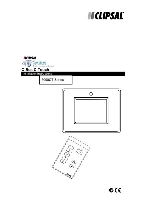
C-<strong>Bus</strong> C-<strong>Touch</strong><br />
<strong>Installation</strong> <strong>Instructions</strong><br />
<strong>5000CT</strong> <strong>Series</strong><br />
2<br />
3<br />
4<br />
5<br />
1
Intelligent Building <strong>Series</strong> C-<strong>Touch</strong> <strong>Installation</strong> <strong>Instructions</strong><br />
Table of Contents<br />
Section …………………………………………………………………………Page<br />
1.0 Product Range.........................................................................................3<br />
2.0 Description ..............................................................................................3<br />
2.1 C-<strong>Touch</strong> Unit .........................................................................................3<br />
2.2 Infrared Remote Control......................................................................4<br />
3.0 Definitions................................................................................................5<br />
4.0 <strong>Installation</strong> Procedure..............................................................................6<br />
4.1 <strong>Installation</strong> Location ..............................................................................6<br />
4.2 Installing Multiple C-<strong>Touch</strong> Controllers..................................................6<br />
5.0 Mounting <strong>Instructions</strong> ..............................................................................7<br />
5.1 Wall Box................................................................................................8<br />
5.2 Mounting Bracket ..................................................................................8<br />
6.0 Wiring Details ........................................................................................12<br />
6.1 C-<strong>Bus</strong> Network Connection.................................................................12<br />
7.0 C-<strong>Bus</strong> System Clock..............................................................................13<br />
8.0 C-<strong>Bus</strong> Power Requirements ..................................................................13<br />
9.0 Power-Up Load Status ..........................................................................13<br />
10.0 Power Surges and Short Circuit Conditions ..........................................14<br />
11.0 Megger Testing......................................................................................14<br />
12.0 Important Notes.....................................................................................14<br />
13.0 Programming Requirements..................................................................14<br />
14.0 C-<strong>Touch</strong> Configuration Software ...........................................................14<br />
15.0 Important Warning.................................................................................14<br />
16.0 Unit Operation .......................................................................................15<br />
17.0 Product Specifications ...........................................................................15<br />
18.0 Standards Complied..............................................................................18<br />
19.0 Limited Warranty ...................................................................................18<br />
Copyright Notice<br />
© Copyright 2001 <strong>Clipsal</strong> Integrated Systems Pty Ltd. All rights reserved.<br />
Trademarks<br />
• <strong>Clipsal</strong> is a registered trademark of Gerard Industries Pty Ltd.<br />
• C-<strong>Bus</strong> is a registered trademark of <strong>Clipsal</strong> Integrated Systems Pty Ltd<br />
• C-<strong>Touch</strong> is a registered trademark of <strong>Clipsal</strong> Integrated Systems Pty Ltd<br />
Intelligent Building <strong>Series</strong> is a registered trademark of <strong>Clipsal</strong> Integrated Systems Pty Ltd<br />
All other logos and trademarks are the property of their respective owners.<br />
Disclaimer<br />
<strong>Clipsal</strong> Integrated Systems reserves the right to change specifications or designs described in<br />
this manual without notice and without obligation.<br />
© Copyright 2001 <strong>Clipsal</strong> Integrated Systems Pty Ltd Page 2
Intelligent Building <strong>Series</strong> C-<strong>Touch</strong> <strong>Installation</strong> <strong>Instructions</strong><br />
1.0 Product Range<br />
SC<strong>5000CT</strong> C-<strong>Touch</strong>, slim line style (includes one 5035TX)<br />
BS<strong>5000CT</strong> C-<strong>Touch</strong>, stainless steel (includes one 5035TX)<br />
BB<strong>5000CT</strong> C-<strong>Touch</strong>, brass (includes one 5035TX)<br />
BG<strong>5000CT</strong> C-<strong>Touch</strong>, gold (includes one 5035TX)<br />
BC<strong>5000CT</strong> C-<strong>Touch</strong>, chrome (includes one 5035TX)<br />
BP<strong>5000CT</strong> C-<strong>Touch</strong>, powder coated (includes one 5035TX)<br />
5035TX C-<strong>Touch</strong> (or Scene Master) hand held infrared remote control.<br />
2.0 Description<br />
The C-<strong>Touch</strong> unit allows sophisticated control of an entire C-<strong>Bus</strong> system from<br />
one location.<br />
Using the C-<strong>Touch</strong> Configuration Software, the C-<strong>Touch</strong> unit can be<br />
configured to look and operate in whatever manner most suits the user. Refer<br />
to the C-<strong>Touch</strong> Programming Guide for further details on programming.<br />
2.1 C-<strong>Touch</strong> Unit<br />
© Copyright 2001 <strong>Clipsal</strong> Integrated Systems Pty Ltd Page 3
Intelligent Building <strong>Series</strong> C-<strong>Touch</strong> <strong>Installation</strong> <strong>Instructions</strong><br />
The C-<strong>Touch</strong> unit comes with the following * :<br />
• C-<strong>Touch</strong> <strong>Touch</strong>screen (LCD covered by protection sheet)<br />
• RS232 cable (DB9 to RJ-45), 2 metres<br />
• User instructions (A5 full colour booklet)<br />
• <strong>Installation</strong> instructions (this booklet)<br />
• CD in slip-in cover :<br />
• C-<strong>Touch</strong> Configuration software<br />
• PDF files of the configuration manual, installation and user<br />
instructions<br />
• Software licence agreement<br />
• Warranty and registration card<br />
• Remote Control (5035TX)<br />
• Wall Box<br />
• 2 x mounting screws (finish to suit <strong>Touch</strong>screen style) in plastic<br />
bag.<br />
* Subject to change without notice<br />
2.2 Infrared Remote Control<br />
The touchscreen comes equipped with a remote control, which is used<br />
to select scenes and turn loads on and off or ramp them to a desired<br />
level. The remote control functionality is set up by the Configuration<br />
Software. The remote control functions will depend upon how C-<strong>Touch</strong><br />
is programmed. If multiple touchscreens are installed, the same<br />
remote control can talk to each of them.<br />
© Copyright 2001 <strong>Clipsal</strong> Integrated Systems Pty Ltd Page 4
Intelligent Building <strong>Series</strong> C-<strong>Touch</strong> <strong>Installation</strong> <strong>Instructions</strong><br />
3.0 Definitions<br />
The following definitions are useful in discussing the C-<strong>Touch</strong> unit:<br />
Term Definition<br />
Load A load is an electrical device connected to mains voltage via<br />
a C-<strong>Bus</strong> Output Unit. Most loads are lights, but may be any<br />
device such as sprinklers, AC Power points, heaters,<br />
projection screens, motors etc.<br />
Group Address This is the C-<strong>Bus</strong> designation for an output channel. It could<br />
represent one or more loads.<br />
Scene A scene is defined as the setting of a combination of various<br />
loads to different levels. The scene can be set up with the<br />
configuration software and assigned to soft keys on the<br />
C-<strong>Touch</strong> unit.<br />
Fade Rate The fade rate indicates the length of time it takes for a<br />
load to ramp to a desired level.<br />
Schedule A schedule is a sequence of events that are to occur at<br />
particular times or dates in the future.<br />
Soft Key An area on the surface of C-<strong>Touch</strong> which can be pressed to<br />
cause something to happen.<br />
Page A page is an assortment of soft keys and graphics that<br />
represents something understandable to the user.<br />
Component A graphical object displayed on a C-<strong>Touch</strong> screen.<br />
Components include soft keys, images, text, clocks,<br />
temperature sensors and other items.<br />
Backlight The back of the screen is illuminated to make it visible when<br />
it is dark. This illumination is called backlight.<br />
Input Unit An input unit is a C-<strong>Bus</strong> unit which the user interacts with to<br />
make things happen on a C-<strong>Bus</strong> Network (C-<strong>Touch</strong> itself, a<br />
key input unit or passive infrared sensor are examples)<br />
Output Unit An output unit delivers power to loads; a relay and dimmer<br />
are examples.<br />
Control A component that can be used to turn loads on or off or<br />
change their level.<br />
© Copyright 2001 <strong>Clipsal</strong> Integrated Systems Pty Ltd Page 5
Intelligent Building <strong>Series</strong> C-<strong>Touch</strong> <strong>Installation</strong> <strong>Instructions</strong><br />
4.0 <strong>Installation</strong> Procedure<br />
4.1 <strong>Installation</strong> Location<br />
It is important to select the right location to install C-<strong>Touch</strong>.<br />
Some considerations are listed below:<br />
• Provide easy access to unit for switching lights and selecting<br />
scenes<br />
• Avoid obstructions to receiving infrared signals from the<br />
Remote Control unit<br />
• Keep C-<strong>Touch</strong> clear of places subject to water, humidity, direct<br />
sunlight or heavy dust<br />
• Allow adequate ventilation.<br />
• Do not cover unit<br />
• C-<strong>Touch</strong> is designed for indoor use only<br />
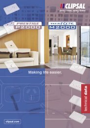
4.2 Installing Multiple C-<strong>Touch</strong> Controllers<br />
Multiple C-<strong>Touch</strong> units can be installed on any C-<strong>Bus</strong> Network. These<br />
units may be programmed to operate dependently or independently of<br />
each other. Care must be taken not to overlap infrared reception<br />
zones for each unit if an infrared remote control is used, else both<br />
units may trigger a scene, with unpredictable results.<br />
WRONG RIGHT<br />
© Copyright 2001 <strong>Clipsal</strong> Integrated Systems Pty Ltd Page 6
Intelligent Building <strong>Series</strong> C-<strong>Touch</strong> <strong>Installation</strong> <strong>Instructions</strong><br />
5.0 Mounting <strong>Instructions</strong><br />
There are four options for mounting the C-<strong>Touch</strong> unit. These are the following:<br />
• Brick with Wall Box<br />
• Timber with Wall Box<br />
• Plasterboard with mounting bracket<br />
• Direct screwing into plugs<br />
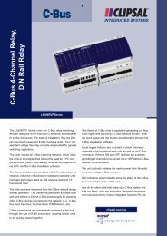
Each of these are described in the following sections. The screen is easiest to<br />
read when viewed directly (straight on). The view is roughly constant up to 15<br />
degrees below the centre line. This illustration shows the best viewing angles.<br />
It is possibly to reprogram the touchscreen for use below the horizontal<br />
viewing axis, in such a case the IR window would be at the bottom of the<br />
screen.<br />
© Copyright 2001 <strong>Clipsal</strong> Integrated Systems Pty Ltd Page 7
Intelligent Building <strong>Series</strong> C-<strong>Touch</strong> <strong>Installation</strong> <strong>Instructions</strong><br />
5.1 Wall Box<br />
C-<strong>Touch</strong> is supplied with a wall box, which allows the unit to be easily<br />
mounted into new or existing installations. The wall box is illustrated<br />
below. This wall box may be fitted into suitably prepared masonry or<br />
attached to a noggin fitted between studs in a timber stud construction.<br />
5.2 Mounting Bracket<br />
<strong>Installation</strong> in a plasterboard wall uses the mounting bracket shown<br />
below.<br />
© Copyright 2001 <strong>Clipsal</strong> Integrated Systems Pty Ltd Page 8
Intelligent Building <strong>Series</strong> C-<strong>Touch</strong> <strong>Installation</strong> <strong>Instructions</strong><br />
The steps in the installation are described in the five figures which<br />
follow.<br />
1.<br />
2.<br />
Prepare the wall by marking with the<br />
supplied template. Carefully cut out<br />
the hole indicated on the template.<br />
The hole must not deviate beyond the<br />
range of + 3mm and – 0 mm to<br />
ensure a good fit. Loosely<br />
assemble the C-<strong>Touch</strong> unit by<br />
inserting the two long screws<br />
through the side holes and<br />
threading them through the wall<br />
box.<br />
The next step is to push the top end of the wall<br />
bracket through the hole in the wall.<br />
© Copyright 2001 <strong>Clipsal</strong> Integrated Systems Pty Ltd Page 9
Intelligent Building <strong>Series</strong> C-<strong>Touch</strong> <strong>Installation</strong> <strong>Instructions</strong><br />
3.<br />
4.<br />
Then lift the bracket in the hole and<br />
bring the other end of the wall<br />
bracket through the bottom of the<br />
hole. Align the touchscreen with the<br />
cutout.<br />
Once aligned, tighten the screws<br />
equally until the C-<strong>Touch</strong> unit is<br />
tightly fitted to the hole and the wall<br />
bracket is pulled up firmly against<br />
the back surface of the wall. Do not<br />
overtighten.<br />
The cover plate can now be snap fitted<br />
to the C-<strong>Touch</strong> unit.<br />
© Copyright 2001 <strong>Clipsal</strong> Integrated Systems Pty Ltd Page 10
Intelligent Building <strong>Series</strong> C-<strong>Touch</strong> <strong>Installation</strong> <strong>Instructions</strong><br />
5.<br />
Once fitted, the C-<strong>Touch</strong> unit should fit<br />
flush against the front face of the wall<br />
and the screws should bring the wall<br />
bracket tightly against the back surface.<br />
© Copyright 2001 <strong>Clipsal</strong> Integrated Systems Pty Ltd Page 11
Intelligent Building <strong>Series</strong> C-<strong>Touch</strong> <strong>Installation</strong> <strong>Instructions</strong><br />
6.0 Wiring Details<br />
Before proceeding please note: The RJ receptacle on the<br />
back of the C-<strong>Touch</strong> unit must not be connected to C-<strong>Bus</strong>.<br />
The connector is for the serial connection only.<br />
6.1 C-<strong>Bus</strong> Network Connection<br />
<strong>Installation</strong> of C-<strong>Touch</strong> on the C-<strong>Bus</strong> Network requires connection to<br />
the unshielded twisted pair C-<strong>Bus</strong> Network Cable. Connection should<br />
be made using Category 5 data cable, catalogue number 5005C305B.<br />
The C-<strong>Bus</strong> Network Connection is polarity sensitive, and is clearly<br />
marked on the rear of the C-<strong>Touch</strong> unit. Two loop-in / loop-out,<br />
removable terminal blocks are provided for easy installation and<br />
maintenance.<br />
Blue + Orange, C-<strong>Bus</strong> Pos (+)<br />
C-<strong>Bus</strong> Connection Colour C-<strong>Touch</strong><br />
Blue/White + Orange/White, C-<strong>Bus</strong> Neg (-)<br />
Brown + Brown/White, Remote OFF<br />
Green + Green/White, Remote ON<br />
Remote ON Green/White Not Connected<br />
Remote ON Green Not Connected<br />
C-<strong>Bus</strong> Neg (-) Orange/White C-<strong>Bus</strong> Neg (-)<br />
C-<strong>Bus</strong> Pos (+) Blue C-<strong>Bus</strong> Pos (+)<br />
C-<strong>Bus</strong> Neg (-) Blue/White C-<strong>Bus</strong> Neg (-)<br />
C-<strong>Bus</strong> Pos (+) Orange C-<strong>Bus</strong> Pos (+)<br />
Remote OFF Brown/White Not Connected<br />
Remote OFF Brown Not Connected<br />
© Copyright 2001 <strong>Clipsal</strong> Integrated Systems Pty Ltd Page 12
Intelligent Building <strong>Series</strong> C-<strong>Touch</strong> <strong>Installation</strong> <strong>Instructions</strong><br />
The serial connection (not supplied) is wired as follows:<br />
RJ Pin Usage Meaning<br />
1 DCD Data Carrier Detect. Output from a DCE device<br />
2 DSR Data set ready. Output from a DCE device<br />
3 DTR Data Terminal Ready. Output from a DTE device.<br />
Frequently used as an output from a printer to tell<br />
the computer that its buffer is full.<br />
4 GND Signal Ground voltage. All signals are referenced<br />
to this voltage. It is usually the signal ground for<br />
the equipment's electronics.<br />
5 RXD Received data. Serial data flowing from a DCE<br />
device to a DTE device.<br />
6 TXD Transmitted data. Serial data flowing from a DTE<br />
device to a DCE device<br />
7 CTS Clear to send. Output from a DCE device.<br />
8 RTS Request to send. Output from a DTE device.<br />
7.0 C-<strong>Bus</strong> System Clock<br />
The C-<strong>Touch</strong> Control Unit incorporates a software selectable C-<strong>Bus</strong> System<br />
Clock used for synchronising data communications waveforms on the C-<strong>Bus</strong><br />
Network. No more than three units on any C-<strong>Bus</strong> Network should have active<br />
Clock circuitry, so this option would normally be disabled using the C-<strong>Bus</strong><br />
<strong>Installation</strong> Software.<br />
8.0 C-<strong>Bus</strong> Power Requirements<br />
The C-<strong>Touch</strong> Unit draws 40mA from the C-<strong>Bus</strong> Network. Adequate C-<strong>Bus</strong><br />
Power Supply Units must be installed to support the connected devices. If in<br />
doubt, consult the C-<strong>Bus</strong> Calculator – Network Design Verification Software<br />
Utility.<br />
9.0 Power-Up Load Status<br />
All C-<strong>Bus</strong> units have onboard non-volatile memory, which store the operating<br />
state of the unit in case of a C-<strong>Bus</strong> power loss. The levels will be restored by<br />
the C-<strong>Bus</strong> output units when power is restored. C-<strong>Touch</strong> will read these<br />
levels on power up and will reflect the current Group Address levels.<br />
Alternatively, the C-<strong>Touch</strong> unit can be configured to enforce levels upon<br />
startup. Please refer to the Programming Guide for details.<br />
Please refer to the C-<strong>Bus</strong> Manual for information relating to C-<strong>Bus</strong> Power Fail<br />
Recovery Options.<br />
© Copyright 2001 <strong>Clipsal</strong> Integrated Systems Pty Ltd Page 13
Intelligent Building <strong>Series</strong> C-<strong>Touch</strong> <strong>Installation</strong> <strong>Instructions</strong><br />
10.0 Power Surges and Short Circuit Conditions<br />
The mains voltage must be limited to the range specified for any C-<strong>Bus</strong> unit<br />
which is mains powered. Each unit incorporates transient protection circuitry,<br />
however external power surge protection devices should be used to enhance<br />
system immunity to power surges. It is strongly recommended that<br />
overvoltage equipment such as the <strong>Clipsal</strong> 970 is installed at the switchboard.<br />
11.0 Megger Testing<br />
Megger testing of an electrical installation that has C-<strong>Bus</strong> units connected will<br />
not cause any damage to C-<strong>Bus</strong> units. Since C-<strong>Bus</strong> units contain electronic<br />
components, the installer should interpret megger readings with due regard to<br />
the nature of the circuit connection.<br />
Megger testing must never be performed on the C-<strong>Bus</strong> data cabling or<br />
terminals as it may degrade the performance of the Network.<br />
12.0 Important Notes<br />
• An Electrician’s Licence is not required to install C-<strong>Touch</strong> units.<br />
• Do not connect mains to C-<strong>Touch</strong> units.<br />
13.0 Programming Requirements<br />
The C-<strong>Touch</strong> Control Unit must be programmed to set a unique identification<br />
(Unit Address) and the mode of operation on the C-<strong>Bus</strong> Network. The C-<strong>Bus</strong><br />
<strong>Installation</strong> Software can be used to configure the:<br />
• Unit Address<br />
• Clock<br />
• Burden<br />
14.0 C-<strong>Touch</strong> Configuration Software<br />
C-<strong>Touch</strong> Configuration Software is provided on CD-ROM with the C-<strong>Touch</strong><br />
Unit. To install the software, simply insert the CD into the CD Drive of your<br />
personal computer or laptop and follow the on-screen prompts.<br />
The CD-ROM also contains Online Documentation. Please refer to the<br />
C-<strong>Touch</strong> Programming Reference for further information relating to the<br />
programming of the C-<strong>Touch</strong>.<br />
Once the configuration of a customer installation is complete, the project<br />
should be written to a disk and provided to the customer or archived at your<br />
premises for future reference.<br />
15.0 Important Warning<br />
The use of any non C-<strong>Bus</strong> Software in conjunction with the hardware<br />
installation without the written consent of <strong>Clipsal</strong> Integrated Systems may void<br />
any warranties applicable to the hardware.<br />
© Copyright 2001 <strong>Clipsal</strong> Integrated Systems Pty Ltd Page 14
Intelligent Building <strong>Series</strong> C-<strong>Touch</strong> <strong>Installation</strong> <strong>Instructions</strong><br />
16.0 Unit Operation<br />
The many powerful features of C-<strong>Touch</strong> are fully described in the C-<strong>Touch</strong><br />
User’s Guide. Topics covered include:<br />
• Scene Selection<br />
• Dimming Controls<br />
• Using the Remote Control<br />
• Page navigation<br />
Please consult that document for further details on the operation of your<br />
C-<strong>Touch</strong>.<br />
17.0 Product Specifications<br />
Parameter Description<br />
Catalogue Number <strong>5000CT</strong> C-<strong>Touch</strong> Control Unit<br />
C-<strong>Bus</strong> Supply Voltage 15-36V DC @ 40mA required for normal<br />
operation. Does not provide current to the C-<br />
<strong>Bus</strong> Network<br />
AC Input Impedance 50kΩ @ 1 kHz<br />
Electrical Isolation 3.75 kV RMS from C-<strong>Bus</strong> to mains (provided<br />
externally to <strong>5000CT</strong>A)<br />
Control Functions Load switching and dimming<br />
Scenes<br />
Schedules<br />
Maximum number of controlled loads 100 Group Addresses on each of 10<br />
Applications<br />
Status indicators User configurable<br />
Maximum Number of C-<strong>Touch</strong> Units on a 50<br />
single C-<strong>Bus</strong> Network<br />
Night Light Option Allows permanent LED illumination at low<br />
brightness level<br />
Warm-Up Time 1 minute<br />
Network Clock Software selectable<br />
C-<strong>Bus</strong> Connection 2 X Loop-in/Loop-out Removable Terminal<br />
blocks provided 0.2-15 mm 2 (24-16 AWG)<br />
(see section 6 in the <strong>Installation</strong> <strong>Instructions</strong><br />
for the pin out)<br />
Dimensions 152 x 115 x 42 mm (L x W x H)<br />
Weight 365g<br />
Mounting Centres 124mm<br />
Operating Temperature Range 0-45 °C<br />
Operating Humidity Range 10-95% R.H.<br />
Colour Stainless Steel, Brass, Powder Coat<br />
© Copyright 2001 <strong>Clipsal</strong> Integrated Systems Pty Ltd Page 15
Intelligent Building <strong>Series</strong> C-<strong>Touch</strong> <strong>Installation</strong> <strong>Instructions</strong><br />
All Dimensions in millimetres<br />
© Copyright 2001 <strong>Clipsal</strong> Integrated Systems Pty Ltd Page 16
Intelligent Building <strong>Series</strong> C-<strong>Touch</strong> <strong>Installation</strong> <strong>Instructions</strong><br />
5035TX Infrared Remote Control<br />
Parameter Description<br />
Catalogue Number 5035TX Infra-red Remote Control<br />
Supply Voltage 3V DC required for normal operation.<br />
Transmission range reduces with reducing<br />
battery voltage<br />
Battery Lithium “Coin” Battery CR2025 (or<br />
equivalent)<br />
Battery Shelf Life Approximately 1 year<br />
Infra-red Transmission Range<br />
≤15 m at 90º to C-<strong>Touch</strong> unit<br />
Control Functions 8 membrane buttons comprising<br />
5 general purpose buttons<br />
1 master off button<br />
1 up and 1 down button<br />
Dimensions 86 x 54 x 8mm (L x W x H)<br />
Weight 28g<br />
Colour Black<br />
Infrared Remote Control dimensions<br />
No user serviceable parts inside.<br />
© Copyright 2001 <strong>Clipsal</strong> Integrated Systems Pty Ltd Page 17
Intelligent Building <strong>Series</strong> C-<strong>Touch</strong> <strong>Installation</strong> <strong>Instructions</strong><br />
18.0 Standards Complied<br />
Standard Title<br />
AS/NZS 3100:1997 inc Amd. 5 General Requirements for Electrical Equipment<br />
AS/NZS 3260:1993 inc Amd. 4 Approval and test specification – Safety of<br />
information technology and business equipment<br />
AS/NZS 3108:1994 inc Amd. 6 Requirements for Safety Extra Low Voltage<br />
IEC 742:1983 Amdt (1) IEC 60742 Isolating transformers and safety isolating<br />
Am1 Ed 1.0b 1983 (Am 1992). transformers - Requirements<br />
AS/NZS 3548:1995 A1, A2<br />
Information Technology Equipment Radio Frequency<br />
IEC/CISPR 22:1995 A1 A2<br />
Emissions Standard<br />
EN 55022: 1998<br />
Information Technology Equipment Radio Frequency<br />
IEC/CISPR 22:1997 A1<br />
Emissions Standard<br />
EN 55024: 1998<br />
Information Technology Equipment Immunity<br />
CISPR 24:1997<br />
Standard<br />
EN 61000-3-2:1995 A1, A2<br />
IEC 61000-3-2:1995 A1, A2<br />
Harmonic Current Emissions Standard<br />
EN 61000-3-3:1995<br />
IEC 61000-3-3: 1995<br />
Voltage Fluctuations and Flicker Standard<br />
EN 61000-4-2<br />
Immunity to Electrostatic Discharge<br />
IEC 61000-4-2<br />
Basic Standard<br />
EN 61000-4-3<br />
Immunity to Radio Frequency Electromagnetic Field<br />
IEC 61000-4-3<br />
Basic Standard<br />
EN 61000-4-4<br />
Immunity to Electrical Fast Transients<br />
IEC 61000-4-4<br />
EN 61000-4-5<br />
IEC 61000-4-5<br />
Basic Standard<br />
Immunity to Electrical Surges<br />
Basic Standard<br />
BS/EN 61000-4-6 Continuous Radiofrequency emissions<br />
89/336/EEC European Union Directive on Electromagnetic<br />
Compatibility<br />
19.0 Limited Warranty<br />
The C-<strong>Touch</strong> product carries a two year warranty against manufacturing<br />
defects (refer to Warranty Statement), with the following exclusions :<br />
Infra-red Remote control Limited to 30 day warranty on battery<br />
condition as supplied<br />
C-<strong>Touch</strong> Configuration software Limited 90 day warranty on software<br />
media only<br />
© Copyright 2001 <strong>Clipsal</strong> Integrated Systems Pty Ltd Page 18
Further Information<br />
For further information about programming and configuring C-<strong>Touch</strong>, please consult the<br />
documentation supplied (these documents are also provided in pdf form on the distribution<br />
disk):<br />
• C-<strong>Touch</strong> <strong>Installation</strong> <strong>Instructions</strong><br />
The printed booklet you are reading now contains detailed information for the<br />
installer regarding unit mounting, wiring, and C-<strong>Bus</strong> Network requirements.<br />
C-<strong>Touch</strong> features and specifications are also presented.<br />
• C-<strong>Touch</strong> User’s Guide<br />
Printed booklet supplied with C-<strong>Touch</strong>, to be left on-site for the customer. It<br />
contains information about C-<strong>Touch</strong> operation, general care and use instructions<br />
• C-<strong>Touch</strong> Programming Reference<br />
The C-<strong>Touch</strong> Programming Reference is provided on CD in electronic format<br />
(Portable Document File (PDF), and requires Adobe Acrobat Reader v4.0 or<br />
higher to view or print). It presents a comprehensive guide to programming<br />
requirements and advanced configuration capabilities of C-<strong>Touch</strong>.<br />
• Technical Support and Troubleshooting<br />
For further assistance in using C-<strong>Touch</strong>, please consult your nearest <strong>Clipsal</strong><br />
Integrated Systems Sales Representative or Technical Support Officer.<br />
Technical Support Hotline 1-300-722-247 (Cost 25¢ a call)<br />
Technical Support Email techsupport.cis@clipsal.com.au<br />
Sales Support Email sales.cis@clipsal.com.au<br />
<strong>Clipsal</strong> Integrated Systems Website clipsal.com/cis<br />
Products of <strong>Clipsal</strong> Integrated Systems Pty Ltd<br />
ABN 15 089 444 931<br />
Head Office<br />
12 Park Terrace, Bowden<br />
South Australia 5007<br />
International Phone +61 8 8269 0560<br />
International Fax +61 8 8346 0845<br />
Internet clipsal.com/cis<br />
E-Mail cis@clipsal.com.au 1036264