975-0466-01-01 - Xantrex - GT2.8-GT5 Series Inverters ... - Clipsal
975-0466-01-01 - Xantrex - GT2.8-GT5 Series Inverters ... - Clipsal
975-0466-01-01 - Xantrex - GT2.8-GT5 Series Inverters ... - Clipsal

Create successful ePaper yourself
Turn your PDF publications into a flip-book with our unique Google optimized e-Paper software.
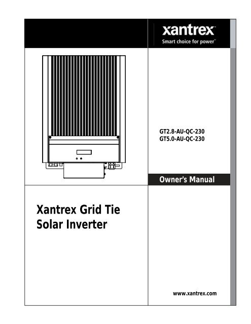
<strong>Xantrex</strong> Grid Tie<br />
Solar Inverter<br />
<strong>GT2.8</strong>-AU-QC-230<br />
<strong>GT5</strong>.0-AU-QC-230<br />
Owner’s Manual<br />
www.xantrex.com
<strong>Xantrex</strong> Grid Tie Solar Inverter<br />
Owner’s Manual
Trademarks<br />
<strong>Xantrex</strong>, Smart choice for power, and Xanbus are trademarks of Schneider Electric, registered in the United States<br />
and other countries. Other trademarks, registered trademarks, and product names are the property of their respective<br />
owners and are used herein for identification purposes only.<br />
Notice of Copyright<br />
Copyright © April 2009, July 2009, November 2009, March 2<strong>01</strong>0 <strong>Xantrex</strong> Technology Inc. No part of this document<br />
may be reproduced in any form or disclosed to third parties without the express written consent of:<br />
<strong>Xantrex</strong> Technology Inc.<br />
161-G South Vasco Road<br />
Livermore, California<br />
USA 94551<br />
<strong>Xantrex</strong> Technology Inc. reserves the right to revise this document and to periodically make changes to the content<br />
hereof without obligation or organization of such revisions or changes unless required to do so by prior arrangement.<br />
Exclusion for Documentation<br />
Unless specifically agreed to in writing, <strong>Xantrex</strong> Technology Inc. (“<strong>Xantrex</strong>”)<br />
(A) MAKES NO WARRANTY AS TO THE ACCURACY, SUFFICIENCY OR SUITABILITY OF ANY TECHNICAL OR OTHER<br />
INFORMATION PROVIDED IN ITS MANUALS OR OTHER DOCUMENTATION;<br />
(B) ASSUMES NO RESPONSIBILITY OR LIABILITY FOR LOSSES, DAMAGES, COSTS OR EXPENSES, WHETHER SPECIAL,<br />
DIRECT, INDIRECT, CONSEQUENTIAL OR INCIDENTAL, WHICH MIGHT ARISE OUT OF THE USE OF SUCH INFORMATION.<br />
THE USE OF ANY SUCH INFORMATION WILL BE ENTIRELY AT THE USER’S RISK; AND<br />
(C) REMINDS YOU THAT IF THIS MANUAL IS IN ANY LANGUAGE OTHER THAN ENGLISH, ALTHOUGH STEPS HAVE BEEN<br />
TAKEN TO MAINTAIN THE ACCURACY OF THE TRANSLATION, THE ACCURACY CANNOT BE GUARANTEED. APPROVED<br />
XANTREX CONTENT IS CONTAINED WITH THE ENGLISH LANGUAGE VERSION WHICH IS POSTED AT<br />
WWW.XANTREX.COM.<br />
Date and Revision<br />
March 2<strong>01</strong>0 Revision D<br />
Document Part Number<br />
<strong>975</strong>-<strong>0466</strong>-<strong>01</strong>-<strong>01</strong><br />
Product Part Numbers<br />
864-1030 (<strong>GT2.8</strong>-AU-QC-230) and 864-1039-<strong>01</strong> (<strong>GT5</strong>.0-AU-QC-230)<br />
Contact Information<br />
Telephone: 1 650 351 8237<br />
Fax: 1 604 422 2756<br />
Email: RE.TechSupport@schneider-electric.com<br />
Web: www.xantrex.com
About This Manual<br />
Scope<br />
Audience<br />
Organization<br />
The purpose of this Owner’s Manual is to provide explanations and procedures<br />
for installing, operating, maintaining, and troubleshooting the <strong>Xantrex</strong> Grid Tie<br />
Solar Inverter.<br />
The manual provides safety guidelines, detailed planning and setup information. It<br />
provides procedures for installing the inverter and information about operating<br />
and troubleshooting the unit. It does not provide details about particular brands of<br />
photovoltaic (PV) panels. You need to consult individual PV manufacturers for<br />
this information.<br />
Chapter 1 and Chapter 5 are intended for anyone who needs to operate the<br />
<strong>Xantrex</strong> Grid Tie Solar Inverter. Operators must be familiar with all the safety<br />
regulations pertaining to operating high-voltage equipment as dictated by local<br />
code. Operators must also have a complete understanding of this equipment’s<br />
features and functions. Do not to use this product unless it has been installed by a<br />
qualified installer in accordance with the instructions in Chapter 2, “Installation”.<br />
Chapter 2, Chapter 3, Chapter 4, and Chapter 6 are intended for qualified<br />
installers who need to install the <strong>Xantrex</strong> Grid Tie Solar Inverter. Qualified<br />
installers have the training and experience in solar power systems to safely and<br />
correctly follow these instructions and the applicable electrical and building<br />
codes, in order to design and install a system that is safe and will operate correctly.<br />
Qualified installers have an awareness of the hazards involved in performing<br />
electrical installation work and how to reduce those hazards. Only qualified<br />
personnel should perform the installation, commissioning and maintenance of the<br />
GT Inverter.<br />
This manual is organized into six chapters and an appendix.<br />
Chapter 1, “Introduction”, contains information about the features and functions<br />
of the <strong>Xantrex</strong> Grid Tie Solar Inverter.<br />
Chapter 2, “Installation”, provides information about planning for and installing<br />
the GT Inverter. It contains information to help you plan wire routes, ensure your<br />
PV array provides necessary power, and find a suitable location for installation.<br />
<strong>975</strong>-<strong>0466</strong>-<strong>01</strong>-<strong>01</strong> iii
About This Manual<br />
Conventions Used<br />
Abbreviations Used<br />
Chapter 3, “Wiring the Inverter”, provides procedures for making DC and AC<br />
wiring connections for single and multiple inverter installations. This chapter also<br />
includes information about communications wiring and using GT-View<br />
monitoring software.<br />
Chapter 4, “Starting the Inverter”, contains information on starting up the <strong>Xantrex</strong><br />
Grid Tie Solar Inverter and performing a functional test.<br />
Chapter 5, “Monitoring the Inverter”, contains information for understanding the<br />
LCD screens and the LED indicators.<br />
Chapter 6, “Maintenance and Troubleshooting”, contains information about how to<br />
provide general maintenance for the <strong>Xantrex</strong> Grid Tie Solar Inverter. It also<br />
provides information about troubleshooting the unit.<br />
Appendix A, “Specifications”, contains information about the electrical and<br />
environmental specifications of the <strong>Xantrex</strong> Grid Tie Solar Inverter.<br />
The following conventions are used in this guide.<br />
WARNING<br />
Warnings identify conditions that could result in personal injury or loss of life.<br />
CAUTION<br />
Cautions identify conditions or practices that could result in damage to the unit or other<br />
equipment.<br />
Important: These notes describe things that are important for you to know, but not as<br />
serious as a caution or warning.<br />
GT Grid Tie<br />
ISC Short Circuit Current<br />
LCD Liquid Crystal Display<br />
LED Light Emitting Diode<br />
MPPT Maximum Power Point Tracking<br />
PMAX Maximum Output Power<br />
P NOM<br />
Nominal Output Power<br />
iv <strong>975</strong>-<strong>0466</strong>-<strong>01</strong>-<strong>01</strong>
Symbols Used<br />
Related Information<br />
PC Personal Computer<br />
PV Photovoltaic<br />
STC Standard Test Condition<br />
Vac Volts AC<br />
Vdc Volts DC<br />
VMP Voltage at Maximum Power<br />
V OC<br />
U PV<br />
Open Circuit Voltage<br />
PV Array DC Voltage<br />
About This Manual<br />
Alternating Current (AC)<br />
Direct Current (DC)<br />
<br />
In this guide: Important information, warnings, or cautions.<br />
On the product: Important information, warnings or cautions with further<br />
explanation in the product guide.<br />
<br />
On the product: Warning, risk of electric shock.<br />
On<br />
the product: Warning, Hot surface—risk of burns.<br />
FOR AUTHORIZED SERVICE PERSONNEL: Before opening cover,<br />
disconnect DC and AC power and wait 30 minutes to allow internal voltages<br />
to reach safe levels.<br />
NOTE: there are no user-serviceable parts inside.<br />
Refer to the operating instructions.<br />
You can find more information about <strong>Xantrex</strong> Technology Inc. as well as its<br />
products and services at www.xantrex.com<br />
<strong>975</strong>-<strong>0466</strong>-<strong>01</strong>-<strong>01</strong> v
Important Safety Instructions<br />
WARNING: Save these instructions<br />
This manual contains important safety and operating instructions. Read and keep this<br />
Owner’s Manual for future reference.<br />
WARNING: Limitations on use<br />
Do not use this GT Inverter in connection with life support systems, medical equipment,<br />
or where human life or medical property may be at stake.<br />
1. Before installing and using the GT Inverter, read all instructions and cautionary markings on the<br />
inverter and in all appropriate sections of this guide.<br />
2. To reduce shock, fire, and energy hazards the installation must be in accordance with all applicable<br />
local installation codes. It is the installer’s responsibility to ensure adherence to applicable codes.<br />
3. To reduce risk of fire hazard, do not cover or obstruct the heat sink.<br />
4. Observe the clearance recommendations as described on page 2–12. Do not install the GT Inverter in a<br />
zero-clearance or non-ventilated compartment. Overheating may result.<br />
5. Use only accessories recommended or sold by the manufacturer. Doing otherwise may result in a risk<br />
of fire, electric shock, or injury to persons.<br />
6. To avoid a risk of fire and electric shock, make sure that all wiring is in good condition and that wire is<br />
not undersized. Do not operate the GT Inverter with damaged or substandard wiring.<br />
7. Do not operate the GT Inverter if it has received a sharp blow, been dropped, or otherwise damaged in<br />
any way. If the GT Inverter is damaged, see the Warranty section.<br />
8. Do not disassemble the GT Inverter. It contains no user-serviceable parts. See Warranty for<br />
instructions on obtaining service. Attempting to service the GT Inverter yourself may result in a risk of<br />
electrical shock or fire and will void your warranty.<br />
9. To reduce the risk of electrical shock, disconnect both AC and DC power from the GT Inverter before<br />
attempting any maintenance or cleaning or working on any circuits connected to the inverter. Turning<br />
off controls will not reduce this risk. Internal capacitors remain charged for up to 30 minutes after<br />
disconnecting all sources of power.<br />
10. The GT Inverter must be provided with an equipment-grounding conductor connected to the AC<br />
ground.<br />
<strong>975</strong>-<strong>0466</strong>-<strong>01</strong>-<strong>01</strong> vii
Safety<br />
Regulatory Compliance<br />
The GT Inverter is compliant with the standards described below.<br />
• Safety: Regulatory Compliance Mark (RCM) based on compliance with AS/NZS 3100 Approval and<br />
test specification – General requirements for electrical equipment<br />
• Electromagnetic Compatibility (EMC): RCM mark based on compliance with:<br />
• EN61000-6-1 Generic standards – Immunity for residential, commercial, and light-industrial<br />
environments<br />
• EN61000-6-3 Generic standards – Emission standard for residential, commercial, and lightindustrial<br />
environments<br />
• EN61000-3-2 Limits for harmonic current emissions<br />
• EN61000-3-3 Limitations of voltage changes, voltage fluctuations, and flicker<br />
• Interconnect: ResLab verified, compliant with the following:<br />
• AS 4777.2-2005 Grid connection of energy systems via inverters – Inverter requirements<br />
• AS 4777.3-2005 Grid connection of energy systems via inverters – Grid protection requirements<br />
The GT Inverter is designed for utility interactive operation. It has complete on-board over-current, overtemperature<br />
and anti-islanding protection. It monitors voltage and frequency of the utility grid and<br />
automatically stops supplying power whenever conditions on the utility grid deviate from standard levels<br />
(see Specifications).<br />
The GT Inverter is equipped with a high frequency transformer that assures galvanic isolation between the<br />
DC side and the utility power grid.<br />
PV Ground Fault Detection<br />
The GT Inverter is equipped with a ground fault detection circuit that measures the impedance to ground of<br />
the array, before connecting to the grid. If a high impedance is not detected, it signals a fault and refuses to<br />
connect. The GT Inverter will remain faulted until the ground fault is remedied and the inverter is<br />
manually reset. See Table 6-1, “Troubleshooting the GT Inverter” on page 6–4.<br />
viii <strong>975</strong>-<strong>0466</strong>-<strong>01</strong>-<strong>01</strong>
Contents<br />
Important Safety Instructions - - - - - - - - - - - - - - - - - - - - - - - - - - - - - - - - - - - - - - - - - - -vii<br />
Regulatory Compliance - - - - - - - - - - - - - - - - - - - - - - - - - - - - - - - - - - - - - - - - - - - - - - - - - - viii<br />
PV Ground Fault Detection - - - - - - - - - - - - - - - - - - - - - - - - - - - - - - - - - - - - - - - - - - - - - - - - viii<br />
1 Introduction<br />
About the <strong>Xantrex</strong> Grid Tie Solar Inverter- - - - - - - - - - - - - - - - - - - - - - - - - - - - - - - - - - - - - - 1–2<br />
Standard Features - - - - - - - - - - - - - - - - - - - - - - - - - - - - - - - - - - - - - - - - - - - - - - - - - - - - - - 1–3<br />
2 Installation<br />
Installation Options - - - - - - - - - - - - - - - - - - - - - - - - - - - - - - - - - - - - - - - - - - - - - - - - - - - - - 2–2<br />
Single Inverter Installation - - - - - - - - - - - - - - - - - - - - - - - - - - - - - - - - - - - - - - - - - - - - - - 2–2<br />
Multiple Inverter Installations - - - - - - - - - - - - - - - - - - - - - - - - - - - - - - - - - - - - - - - - - - - 2–2<br />
Planning the Installation - - - - - - - - - - - - - - - - - - - - - - - - - - - - - - - - - - - - - - - - - - - - - - - - - - 2–2<br />
Inverter Location - - - - - - - - - - - - - - - - - - - - - - - - - - - - - - - - - - - - - - - - - - - - - - - - - - - - 2–4<br />
PV Array Requirements - - - - - - - - - - - - - - - - - - - - - - - - - - - - - - - - - - - - - - - - - - - - - - - 2–5<br />
Grounding Requirements - - - - - - - - - - - - - - - - - - - - - - - - - - - - - - - - - - - - - - - - - - - - - - - 2–7<br />
Routing the Wires - - - - - - - - - - - - - - - - - - - - - - - - - - - - - - - - - - - - - - - - - - - - - - - - - - - 2–8<br />
Preparing for the Installation - - - - - - - - - - - - - - - - - - - - - - - - - - - - - - - - - - - - - - - - - - - - - - - 2–8<br />
Wiring - - - - - - - - - - - - - - - - - - - - - - - - - - - - - - - - - - - - - - - - - - - - - - - - - - - - - - - - - - - 2–8<br />
AC Circuit Breaker Requirements - - - - - - - - - - - - - - - - - - - - - - - - - - - - - - - - - - - - - - - - - 2–9<br />
AC and DC Disconnects - - - - - - - - - - - - - - - - - - - - - - - - - - - - - - - - - - - - - - - - - - - - - - - 2–9<br />
Mounting the Inverter - - - - - - - - - - - - - - - - - - - - - - - - - - - - - - - - - - - - - - - - - - - - - - - - - - - 2–9<br />
Overview - - - - - - - - - - - - - - - - - - - - - - - - - - - - - - - - - - - - - - - - - - - - - - - - - - - - - - - - - 2–9<br />
Tools and Materials Needed - - - - - - - - - - - - - - - - - - - - - - - - - - - - - - - - - - - - - - - - - - - - 2–10<br />
Dimensions - - - - - - - - - - - - - - - - - - - - - - - - - - - - - - - - - - - - - - - - - - - - - - - - - - - - - - - 2–11<br />
Installing the Mounting Bracket - - - - - - - - - - - - - - - - - - - - - - - - - - - - - - - - - - - - - - - - - 2–12<br />
Mounting the Inverter on the Bracket - - - - - - - - - - - - - - - - - - - - - - - - - - - - - - - - - - - - - 2–16<br />
3 Wiring the Inverter<br />
Connecting the DC Wiring - - - - - - - - - - - - - - - - - - - - - - - - - - - - - - - - - - - - - - - - - - - - - - - - 3–2<br />
Equipment Needed - - - - - - - - - - - - - - - - - - - - - - - - - - - - - - - - - - - - - - - - - - - - - - - - - - - 3–3<br />
DC Fuses (<strong>GT5</strong>.0-AU Model Only for Three PV Strings) - - - - - - - - - - - - - - - - - - - - - - - - - 3–3<br />
Connecting the PV Array - - - - - - - - - - - - - - - - - - - - - - - - - - - - - - - - - - - - - - - - - - - - - - 3–5<br />
Connecting Multiple <strong>Inverters</strong> - - - - - - - - - - - - - - - - - - - - - - - - - - - - - - - - - - - - - - - - - - - - - - 3–6<br />
Connecting the AC Wiring - - - - - - - - - - - - - - - - - - - - - - - - - - - - - - - - - - - - - - - - - - - - - - - - 3–7<br />
Making AC Connections for the <strong>GT2.8</strong>-AU Model - - - - - - - - - - - - - - - - - - - - - - - - - - - - - 3–8<br />
Making AC Connections for <strong>GT5</strong>.0-AU Model - - - - - - - - - - - - - - - - - - - - - - - - - - - - - - - - 3–9<br />
<strong>975</strong>-<strong>0466</strong>-<strong>01</strong>-<strong>01</strong> ix
Contents<br />
Communications Wiring for Multiple <strong>Inverters</strong> - - - - - - - - - - - - - - - - - - - - - - - - - - - - - - - - - -3–11<br />
Xanbus Network Technology - - - - - - - - - - - - - - - - - - - - - - - - - - - - - - - - - - - - - - - - - - -3–12<br />
Guidelines for Routing the Network Cables - - - - - - - - - - - - - - - - - - - - - - - - - - - - - - - - - -3–15<br />
Connecting Network Cable between <strong>Inverters</strong> - - - - - - - - - - - - - - - - - - - - - - - - - - - - - - - -3–16<br />
Verifying the Xanbus Network - - - - - - - - - - - - - - - - - - - - - - - - - - - - - - - - - - - - - - - - - -3–17<br />
Communications Wiring for Monitoring a Single Inverter- - - - - - - - - - - - - - - - - - - - - - - - - - -3–17<br />
4 Starting the Inverter<br />
Commissioning Procedure - - - - - - - - - - - - - - - - - - - - - - - - - - - - - - - - - - - - - - - - - - - - - - - - 4–2<br />
Disconnect Test - - - - - - - - - - - - - - - - - - - - - - - - - - - - - - - - - - - - - - - - - - - - - - - - - - - - - - - 4–3<br />
5 Monitoring the Inverter<br />
Monitoring the Front Panel Display- - - - - - - - - - - - - - - - - - - - - - - - - - - - - - - - - - - - - - - - - - 5–2<br />
Front Panel Display Screens and What They Mean - - - - - - - - - - - - - - - - - - - - - - - - - - - - - - - 5–3<br />
Startup Mode - - - - - - - - - - - - - - - - - - - - - - - - - - - - - - - - - - - - - - - - - - - - - - - - - - - - - - 5–3<br />
Normal Operation Mode - - - - - - - - - - - - - - - - - - - - - - - - - - - - - - - - - - - - - - - - - - - - - - 5–5<br />
Offline Mode - - - - - - - - - - - - - - - - - - - - - - - - - - - - - - - - - - - - - - - - - - - - - - - - - - - - - - 5–7<br />
Fault Mode - - - - - - - - - - - - - - - - - - - - - - - - - - - - - - - - - - - - - - - - - - - - - - - - - - - - - - - - 5–8<br />
Special Screens - - - - - - - - - - - - - - - - - - - - - - - - - - - - - - - - - - - - - - - - - - - - - - - - - - - - -5–10<br />
Custom Screens - - - - - - - - - - - - - - - - - - - - - - - - - - - - - - - - - - - - - - - - - - - - - - - - - - - -5–10<br />
Status Indicator Lights- - - - - - - - - - - - - - - - - - - - - - - - - - - - - - - - - - - - - - - - - - - - - - - - - - -5–11<br />
6 Maintenance and Troubleshooting<br />
Factors Affecting GT Inverter Performance - - - - - - - - - - - - - - - - - - - - - - - - - - - - - - - - - - - - 6–2<br />
PV Array Factors - - - - - - - - - - - - - - - - - - - - - - - - - - - - - - - - - - - - - - - - - - - - - - - - - - - 6–2<br />
Other Factors - - - - - - - - - - - - - - - - - - - - - - - - - - - - - - - - - - - - - - - - - - - - - - - - - - - - - - 6–3<br />
Performing General Maintenance - - - - - - - - - - - - - - - - - - - - - - - - - - - - - - - - - - - - - - - - - - - 6–3<br />
Identifying Error/Fault Conditions and Solutions- - - - - - - - - - - - - - - - - - - - - - - - - - - - - - - - - 6–4<br />
A Specifications<br />
Electrical Specifications - - - - - - - - - - - - - - - - - - - - - - - - - - - - - - - - - - - - - - - - - - - - - - - - - A–2<br />
Input - - - - - - - - - - - - - - - - - - - - - - - - - - - - - - - - - - - - - - - - - - - - - - - - - - - - - - - - - - - - A–2<br />
Output - - - - - - - - - - - - - - - - - - - - - - - - - - - - - - - - - - - - - - - - - - - - - - - - - - - - - - - - - - - A–2<br />
Islanding Protection - - - - - - - - - - - - - - - - - - - - - - - - - - - - - - - - - - - - - - - - - - - - - - - - - - A–3<br />
Adjustable Disconnect Settings - - - - - - - - - - - - - - - - - - - - - - - - - - - - - - - - - - - - - - - - - - A–3<br />
Output Power Versus Ambient Temperature - - - - - - - - - - - - - - - - - - - - - - - - - - - - - - - - - A–4<br />
Efficiency - - - - - - - - - - - - - - - - - - - - - - - - - - - - - - - - - - - - - - - - - - - - - - - - - - - - - - - - A–5<br />
Environmental Specifications - - - - - - - - - - - - - - - - - - - - - - - - - - - - - - - - - - - - - - - - - - - - - - A–5<br />
User Display - - - - - - - - - - - - - - - - - - - - - - - - - - - - - - - - - - - - - - - - - - - - - - - - - - - - - - A–5<br />
Display Accuracy - - - - - - - - - - - - - - - - - - - - - - - - - - - - - - - - - - - - - - - - - - - - - - - - - - - A–5<br />
Mechanical Specifications - - - - - - - - - - - - - - - - - - - - - - - - - - - - - - - - - - - - - - - - - - - - - - - - A–6<br />
x <strong>975</strong>-<strong>0466</strong>-<strong>01</strong>-<strong>01</strong>
Contents<br />
Warranty and Return Information - - - - - - - - - - - - - - - - - - - - - - - - - - - - - - - - - - - - WA–1<br />
Index - - - - - - - - - - - - - - - - - - - - - - - - - - - - - - - - - - - - - - - - - - - - - - - - - - - - - - - - - - - - - - - - IX–1<br />
<strong>975</strong>-<strong>0466</strong>-<strong>01</strong>-<strong>01</strong> xi
Contents<br />
xii <strong>975</strong>-<strong>0466</strong>-<strong>01</strong>-<strong>01</strong>
Figures<br />
Figure 1-1 Basic System Overview - - - - - - - - - - - - - - - - - - - - - - - - - - - - - - - - - - - - - - - - - - - - 1–2<br />
Figure 1-2 Main Features of the GT Inverter (<strong>GT5</strong>.0-AU Model Shown) - - - - - - - - - - - - - - - - - - 1–4<br />
Figure 2-1 Installation Options Overview- - - - - - - - - - - - - - - - - - - - - - - - - - - - - - - - - - - - - - - - 2–3<br />
Figure 2-2 GT Inverter mounting orientation - - - - - - - - - - - - - - - - - - - - - - - - - - - - - - - - - - - - - 2–5<br />
Figure 2-3 Installation Overview- - - - - - - - - - - - - - - - - - - - - - - - - - - - - - - - - - - - - - - - - - - - - 2–10<br />
Figure 2-4 GT Inverter Dimensions (<strong>GT5</strong>.0-AU Shown) - - - - - - - - - - - - - - - - - - - - - - - - - - - - 2–11<br />
Figure 2-5 Mounting Bracket and GT Inverter (<strong>GT5</strong>.0-AU Shown) - - - - - - - - - - - - - - - - - - - - - 2–12<br />
Figure 2-6 Examples of Mounting on a Pole or Rails - - - - - - - - - - - - - - - - - - - - - - - - - - - - - - - 2–14<br />
Figure 2-7 Installing the Mounting Bracket using Plywood Support - - - - - - - - - - - - - - - - - - - - - 2–15<br />
Figure 2-8 Proper Placement of the Inverter on the Mounting Bracket (<strong>GT5</strong>.0-AU Model<br />
Shown with Communication Ports Cover On) - - - - - - - - - - - - - - - - - - - - - - - - - - - - 2–16<br />
Figure 3-1 PV Quick Connect Locations - - - - - - - - - - - - - - - - - - - - - - - - - - - - - - - - - - - - - - - - 3–2<br />
Figure 3-2 <strong>GT5</strong>.0-AU DC Fuse Installation - - - - - - - - - - - - - - - - - - - - - - - - - - - - - - - - - - - - - - 3–5<br />
Figure 3-3 DC Connections for a Two-String PV Array - - - - - - - - - - - - - - - - - - - - - - - - - - - - - - 3–6<br />
Figure 3-4 Improper Multiple Inverter Connections - - - - - - - - - - - - - - - - - - - - - - - - - - - - - - - - - 3–7<br />
Figure 3-5 AC Connector (Female) - - - - - - - - - - - - - - - - - - - - - - - - - - - - - - - - - - - - - - - - - - - - 3–9<br />
Figure 3-6 AC Connector Terminals - - - - - - - - - - - - - - - - - - - - - - - - - - - - - - - - - - - - - - - - - - - 3–9<br />
Figure 3-7 <strong>GT5</strong>.0-AU AC Wiring Compartment and Terminal Block - - - - - - - - - - - - - - - - - - - - 3–10<br />
Figure 3-8 Attaching the Protective Bracket - - - - - - - - - - - - - - - - - - - - - - - - - - - - - - - - - - - - - 3–11<br />
Figure 3-9 Network Layout (Communication Ports Cover Installed)- - - - - - - - - - - - - - - - - - - - - 3–12<br />
Figure 3-10 Network Terminator - - - - - - - - - - - - - - - - - - - - - - - - - - - - - - - - - - - - - - - - - - - - - 3–13<br />
Figure 3-11 Location of Xanbus RJ45 Ports (<strong>GT2.8</strong>-AU Shown)- - - - - - - - - - - - - - - - - - - - - - - - 3–14<br />
Figure 3-12 Network Cable - - - - - - - - - - - - - - - - - - - - - - - - - - - - - - - - - - - - - - - - - - - - - - - - - 3–14<br />
Figure 3-13 Replacing the Communication Ports Cover - - - - - - - - - - - - - - - - - - - - - - - - - - - - - - 3–16<br />
Figure 5-1 Front Panel LCD Location - - - - - - - - - - - - - - - - - - - - - - - - - - - - - - - - - - - - - - - - - - 5–2<br />
Figure 5-2 Location of Status Indicator Lights - - - - - - - - - - - - - - - - - - - - - - - - - - - - - - - - - - - 5–11<br />
Figure A-1 Output Power vs. Ambient Temperature (<strong>GT2.8</strong>-AU) - - - - - - - - - - - - - - - - - - - - - - - -A–4<br />
Figure A-2 Output Power vs. Ambient Temperature (<strong>GT5</strong>.0-AU) - - - - - - - - - - - - - - - - - - - - - - - -A–4<br />
<strong>975</strong>-<strong>0466</strong>-<strong>01</strong>-<strong>01</strong> xiii
xiv
Tables<br />
Table 2-1 MPPT Operational Window (<strong>GT2.8</strong>-AU) - - - - - - - - - - - - - - - - - - - - - - - - - - - - - - - - 2–6<br />
Table 2-2 MPPT Operational Window (<strong>GT5</strong>.0-AU) - - - - - - - - - - - - - - - - - - - - - - - - - - - - - - - - 2–6<br />
Table 2-3 Inverter Clearance Requirements - - - - - - - - - - - - - - - - - - - - - - - - - - - - - - - - - - - - - 2–12<br />
Table 3-1 Recommended Fuses - - - - - - - - - - - - - - - - - - - - - - - - - - - - - - - - - - - - - - - - - - - - - - 3–4<br />
Table 3-2 Total Xanbus Network Length - - - - - - - - - - - - - - - - - - - - - - - - - - - - - - - - - - - - - - 3–12<br />
Table 3-3 Network Components and Part Numbers- - - - - - - - - - - - - - - - - - - - - - - - - - - - - - - - 3–15<br />
Table 5-1 Startup Screens on <strong>GT5</strong>.0-AU Front Panel Display- - - - - - - - - - - - - - - - - - - - - - - - - - 5–3<br />
Table 5-2 Normal Operation Default Screen - - - - - - - - - - - - - - - - - - - - - - - - - - - - - - - - - - - - - 5–5<br />
Table 5-3 Normal Operation Screens for All GT <strong>Inverters</strong> - - - - - - - - - - - - - - - - - - - - - - - - - - - - 5–6<br />
Table 5-4 Additional Normal Operation Screens for Each GT Inverter in a Multiple Unit System - 5–7<br />
Table 5-5 Offline Mode Default Display - - - - - - - - - - - - - - - - - - - - - - - - - - - - - - - - - - - - - - - - 5–7<br />
Table 5-6 Offline Mode Screens for All GT <strong>Inverters</strong> - - - - - - - - - - - - - - - - - - - - - - - - - - - - - - - 5–7<br />
Table 5-7 Additional Offline Mode Screens for Each GT Inverter in a Multiple Unit System - - - - 5–8<br />
Table 5-8 Fault Message Screens - - - - - - - - - - - - - - - - - - - - - - - - - - - - - - - - - - - - - - - - - - - - - 5–8<br />
Table 5-9 Additional Fault Mode Screens - - - - - - - - - - - - - - - - - - - - - - - - - - - - - - - - - - - - - - - 5–9<br />
Table 5-10 Special Message Screens - - - - - - - - - - - - - - - - - - - - - - - - - - - - - - - - - - - - - - - - - - 5–10<br />
Table 5-11 Status Indicator LEDs - - - - - - - - - - - - - - - - - - - - - - - - - - - - - - - - - - - - - - - - - - - - 5–11<br />
Table 6-1 Troubleshooting the GT Inverter - - - - - - - - - - - - - - - - - - - - - - - - - - - - - - - - - - - - - - 6–4<br />
<strong>975</strong>-<strong>0466</strong>-<strong>01</strong>-<strong>01</strong> xv
xvi
1 Introduction<br />
Chapter 1, “Introduction”, contains information about the features<br />
and functions of the <strong>Xantrex</strong> Grid Tie Solar Inverter.<br />
The topics in this chapter are organized as follows:<br />
• “About the <strong>Xantrex</strong> Grid Tie Solar Inverter” on page 1–2<br />
• “Standard Features” on page 1–3
Introduction<br />
About the <strong>Xantrex</strong> Grid Tie Solar Inverter<br />
Harvested solar energy<br />
Grid Tie Solar Inverter<br />
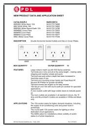
Figure 1-1 Basic System Overview<br />
The <strong>Xantrex</strong> Grid Tie Solar Inverter (GT Inverter) is designed to convert solar<br />
electric (photovoltaic or PV) power into utility-grade electricity that can be used<br />
by the home or sold to the local power company.<br />
Installing the GT Inverter consists of mounting it to the wall and connecting the<br />
DC input to a PV array and the AC output to the utility. See Figure 1-1 for a<br />
simple diagram of a typical installation.<br />
In order to operate, the GT Inverter must have grid power available and<br />
connected. It will not provide backup power if the AC grid fails.<br />
Photovoltaic (PV) Panels—<br />
PV Array<br />
DC converted to AC<br />
GT Inverter<br />
Main Utility<br />
Service Panel<br />
Power routed to utility grid<br />
1–2 <strong>975</strong>-<strong>0466</strong>-<strong>01</strong>-<strong>01</strong><br />
0 0 0 0 0 0 0 8 kWh<br />
230 V 10( 60) A 50 Hz<br />
Utility Meter<br />
Utility Grid
Standard Features<br />
PV compatibility The GT Inverter is designed to take advantage of solar modules configured as<br />
high voltage PV string arrays—single crystalline, poly crystalline, or thin film—<br />
with a 195 to 550 Vdc output voltage Maximum Power Point range (240 to 550<br />
Vdc for the <strong>GT5</strong>.0-AU model).<br />
Maximum Power<br />
Point Tracking<br />
(MPPT)<br />
The GT Inverter uses <strong>Xantrex</strong> proprietary Maximum Power Point Tracking<br />
(MPPT) technology to harvest the maximum amount of energy from the solar<br />
array. MPPT learns your array’s specific characteristics, maximizing its output at<br />
all times.<br />
High efficiency The high-frequency, solid-state design of the GT Inverter is extremely efficient—<br />
up to 96%.<br />
Expandable Multiple GT <strong>Inverters</strong> may be networked together for increased net metering<br />
capacity or future system growth.<br />
Communications<br />
protocol<br />
Standard Features<br />
The GT Inverter uses the Xanbus communications protocol, enabling it to<br />
communicate with multiple units connected within the system. For more<br />
information, see “Xanbus Network Technology” on page 3–12.<br />
The GT Inverter has the following standard features:<br />
• Outdoor rated and weatherproof inverter (IP54), with external heat sink to<br />
protect power electronic components<br />
• Quick-connect connections for DC input (both models) and for AC output<br />
(<strong>GT2.8</strong>-AU model only)<br />
• Liquid Crystal Display (LCD) to provide easy-to-read system status and daily<br />
cumulative energy production information<br />
• Two LED indicator lights to provide status and ground fault indication<br />
<strong>975</strong>-<strong>0466</strong>-<strong>01</strong>-<strong>01</strong> 1–3
Introduction<br />
Heat sink<br />
LCD<br />
DC quick-connects<br />
Communication<br />
ports cover<br />
LED indicator lights<br />
AC connection<br />
Mounting slots (five)<br />
Figure 1-2 Main Features of the GT Inverter (<strong>GT5</strong>.0-AU Model Shown)<br />
1–4 <strong>975</strong>-<strong>0466</strong>-<strong>01</strong>-<strong>01</strong>
2 Installation<br />
Chapter 2, “Installation”, provides information about planning for and<br />
installing the GT Inverter. It contains information to help you plan<br />
wire routes, ensure your PV array provides necessary power, and find<br />
a suitable location for installation.<br />
The topics in this chapter are organized as follows:<br />
• “Installation Options” on page 2–2<br />
• “Planning the Installation” on page 2–2<br />
• “Preparing for the Installation” on page 2–8<br />
• “Mounting the Inverter” on page 2–9.<br />
This chapter for use by qualified personnel only
Installation<br />
Installation Options<br />
Single Inverter Installation<br />
Multiple Inverter Installations<br />
Planning the Installation<br />
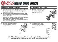
The GT Inverter may be installed as a single inverter for a single PV array of up to<br />
two PV strings (up to three PV strings for the <strong>GT5</strong>.0-AU model), or in a multiple<br />
inverter configuration for multiple PV arrays (see Figure 2-1 for diagrams of both<br />
options).<br />
In this configuration, a single inverter collects the harvested solar energy and<br />
routes the power to the main utility service panel and the utility grid.<br />
If multiple inverters are used, each inverter must be wired to an independent PV<br />
array. In this configuration, each inverter collects the harvested solar energy from<br />
a separate PV array and routes the power to the main utility service panel and the<br />
utility grid.<br />
Communications between inverters is optional, but can be enabled by installing<br />
communications cabling to the inverter RJ45 ports. See “Connecting Network<br />
Cable between <strong>Inverters</strong>” on page 3–16.<br />
The following issues need to be considered when planning for an installation<br />
using the GT Inverter. See the specified sections for more information.<br />
• “Inverter Location” on page 2–4<br />
• “PV Array Requirements” on page 2–5<br />
• “Grounding Requirements” on page 2–7<br />
• “Routing the Wires” on page 2–8.<br />
Ensure that you have obtained all permits required by local authorities or utilities<br />
before commencing installation.<br />
2–2 <strong>975</strong>-<strong>0466</strong>-<strong>01</strong>-<strong>01</strong><br />
This chapter for use by qualified personnel only
Harvested solar energy<br />
Photovoltaic (PV) Panels—<br />
PV Array<br />
Photovoltaic Panels—<br />
Multiple PV Arrays<br />
PV Array #1<br />
PV Array #2<br />
Harvested<br />
solar energy<br />
Grid Tie<br />
Solar<br />
Inverter<br />
Grid Tie Solar<br />
Inverter<br />
GT Inverter<br />
Grid Tie<br />
Solar<br />
Inverter<br />
Figure 2-1 Installation Options Overview<br />
Single Inverter Installation<br />
DC converted to AC<br />
Main Utility<br />
Service Panel<br />
Multiple Inverter Installation<br />
Harvested solar energy<br />
GT Inverter #1 GT Inverter #2<br />
DC converted to AC<br />
DC converted to AC<br />
Main Utility<br />
Service Panel<br />
Planning the Installation<br />
<strong>975</strong>-<strong>0466</strong>-<strong>01</strong>-<strong>01</strong> 2–3<br />
This chapter for use by qualified personnel only<br />
Surplus power routed<br />
to utility grid<br />
0 0 0 0 kW<br />
0 0 0 8 h<br />
230V<br />
10 (60 ) 50<br />
A Hz<br />
Utility Meter<br />
Surplus power routed<br />
to Utility Grid<br />
0 0 0 0 kW<br />
0 0 0 8 h<br />
230V<br />
10 (60 ) 50<br />
A Hz<br />
Utility Meter<br />
Utility Grid<br />
Utility Grid
Installation<br />
Inverter Location<br />
WARNING: Burn hazard<br />
Do not install in normal traffic areas or other locations where people can accidentally<br />
come into contact with the front of the inverter. High temperatures can be present on the<br />
face of the inverter that can cause skin burns if accidentally touched..<br />
Inverter failure due to improper installation will void the inverter warranty.<br />
Consider the following when determining where to install the inverter.<br />
Fire Safety • Do not install anywhere near combustible or flammable materials such<br />
as stored fuels and solvents.<br />
Indoor/<br />
Outdoor<br />
• The GT Inverter can be mounted indoors or outdoors.<br />
• In outdoor installations the GT Inverter is rated for exposure to rain<br />
and snow, but it should be located away from lawn sprinklers and<br />
other sources of spray.<br />
Orientation • The GT Inverter must be mounted vertically (with DC and AC<br />
connectors facing down) on a wall or pole. See Figure 2-2.<br />
Temperature • Make sure the GT Inverter is mounted in a location where the ambient<br />
temperature range is -25 to 65 °C.<br />
• At extreme cold temperatures, the front panel LCD may not function<br />
normally. At higher temperatures, the unit may derate power. See<br />
“Environmental Specifications” on page A–5 and “Output Power vs.<br />
Ambient Temperature (<strong>GT2.8</strong>-AU)” on page A–4.<br />
Ground<br />
Clearance<br />
• Outdoors, the GT Inverter requires at least 100 cm of clearance<br />
between the bottom of the unit and the ground. This clearance helps<br />
prevent water from splashing onto the bottom of the unit.<br />
• Install the GT Inverter at a height at which the LCD is easily readable.<br />
Distance • To minimize power losses in wiring, ensure that wire lengths between<br />
the PV array and the GT Inverter and between the inverter and the<br />
Main Utility Service Panel are kept to a minimum.<br />
• Maximum distances will depend on wire gauges used and PV array<br />
output voltages. To minimize system failures due to AC voltage faults,<br />
<strong>Xantrex</strong> recommends sizing the AC and DC wiring to have a<br />
maximum 1 to 1.5% voltage drop.<br />
Debris free • Excessive debris (such as dust, leaves, and cobwebs) can accumulate<br />
on the unit, interfering with wiring connections and ventilation. Do<br />
not install in a location where debris can accumulate (such as under a<br />
tree).<br />
2–4 <strong>975</strong>-<strong>0466</strong>-<strong>01</strong>-<strong>01</strong><br />
This chapter for use by qualified personnel only
PV Array Requirements<br />
Equipment and Installation Recommendations<br />
Equipment<br />
recommendations<br />
Installation<br />
recommendations<br />
MPPT Requirements<br />
MPPT operational<br />
window<br />
Figure 2-2 GT Inverter mounting orientation<br />
Planning the Installation<br />
Important: The PV array should be free of shade. This requirement includes even<br />
small obstructions such as antennas, chimneys, and power lines. As well, be aware of<br />
potential obstructions from growing trees and neighboring buildings. A small amount of<br />
shade can have a disproportionately high impact on system performance.<br />
• All electrical equipment should be approved for the voltage and current<br />
ratings necessary for the application.<br />
• All wiring should be sized correctly to minimize voltage drop.<br />
• All exposed wires or conduits should be sunlight resistant.<br />
• All required overcurrent protection and disconnecting means should be<br />
included in the system and accessible for maintenance.<br />
• All electrical terminations should be fully tightened, secured, and strain<br />
relieved as appropriate.<br />
• All mounting equipment should be installed according to the manufacturer’s<br />
specifications.<br />
• All wires, conduit, exposed conductors and electrical boxes should be secured<br />
and supported according to code requirements.<br />
The MPPT software maximizes the output energy of solar arrays as long as the<br />
operating voltage is within the MPPT operational window. Ensure that the PV<br />
array used in the system operates within the MPPT operational window.<br />
Effects of array voltages outside of the MPPT operational window are shown in<br />
Table 2-1.<br />
<strong>975</strong>-<strong>0466</strong>-<strong>01</strong>-<strong>01</strong> 2–5<br />
This chapter for use by qualified personnel only
Installation<br />
Array Voltage and<br />
Current Limits<br />
Table 2-1 MPPT Operational Window (<strong>GT2.8</strong>-AU)<br />
Voltage Effect of Array Voltage Inverter Mode<br />
< 195 Vdc Operating voltage shifts to 195 Vdc; the array is<br />
not at its maximum power point<br />
The solar array should be sized such that its maximum voltage output does not<br />
exceed the limits of the MPPT operational window (195/240 to 550 Vdc). See<br />
“Guidelines for Matching PV Array Size to <strong>Xantrex</strong> Grid Tie Solar Inverter<br />
Input”.<br />
Likewise, ensure that the I SC (short circuit current) rating of the array at any<br />
temperature does not exceed the short circuit current rating of the inverter.<br />
Guidelines for Matching PV Array Size to <strong>Xantrex</strong> Grid Tie Solar Inverter Input<br />
For determining the number of panels required in the PV string (panels connected<br />
in series), you must ensure that the following three requirements are met:<br />
1. To avoid damage to the inverter, ensure that the PV array output will never<br />
exceed 600 Vdc under any conditions.<br />
2. Do not exceed the maximum array short circuit-current rating marked on the<br />
inverter.<br />
2–6 <strong>975</strong>-<strong>0466</strong>-<strong>01</strong>-<strong>01</strong><br />
This chapter for use by qualified personnel only<br />
Low power<br />
195 to 550 Vdc Maximum harvest of solar energy MPPT window<br />
550 to 600 Vdc Reduced harvest of solar energy Power derating<br />
> 600 Inverter stops selling surplus energy and shuts<br />
down. Voltage above 600 Vdc may damage the<br />
inverter.<br />
Shutdown<br />
Table 2-2 MPPT Operational Window (<strong>GT5</strong>.0-AU)<br />
Voltage Effect of Array Voltage Inverter Mode<br />
< 240 Vdc Operating voltage shifts to 240 Vdc; the array is<br />
not at its maximum power point<br />
Low power<br />
240 to 550 Vdc Maximum harvest of solar energy MPPT window<br />
550 to 580 Vdc Reduced harvest of solar energy Power derating<br />
> 580 Inverter stops selling surplus energy and shuts<br />
down. Voltage above 600 Vdc may damage the<br />
inverter.<br />
Shutdown<br />
CAUTION: Equipment Damage<br />
The array voltage must never exceed 600 V OC (open circuit voltage) under any condition.
Grounding Requirements<br />
AC Grounding<br />
DC Grounding<br />
Planning the Installation<br />
3. To achieve maximum energy harvest from your array, ensure that the VMP (voltage at maximum power) does not drop below 195/240 Vdc or increase<br />
above 550 Vdc under most conditions.<br />
Guidelines to help you meet these requirements:<br />
• Consider the expected VOC of the string under all possible conditions. The<br />
panel manufacturer provides a VOC rating per panel, but it is usually rated at<br />
25 °C. Ensure that the VOC rating at the coldest ambient temperature does not<br />
exceed 600 VOC. Panel voltage increases in cold temperatures—the panel<br />
manufacturer should be able to provide a coefficient of voltage increase per<br />
degree.<br />
• Panel voltage decreases in high temperatures. This will affect the panels’<br />
VMP . Again, the manufacturer’s coefficient must be used with the highest<br />
expected temperature to determine the minimum VMP .<br />
Once you know the specifications of your panels, all these factors will help<br />
determine the maximum and minimum number of panels that can be used.<br />
Visit the Support page at www.xantrex.com to use an online PV array sizing tool.<br />
WARNING: Shock hazard<br />
The GT Inverter must be grounded in accordance with the following and with all<br />
applicable codes.<br />
AC system grounding is governed by local codes. The <strong>GT2.8</strong>-AU and <strong>GT5</strong>.0-AU<br />
inverters will function properly in AC systems with a grounded neutral or with<br />
two ungrounded lines. The GT Inverter must be provided with an equipment<br />
grounding conductor connected to the grounding terminal on the AC output<br />
connector (<strong>GT2.8</strong>-AU) or in the wiring compartment (<strong>GT5</strong>.0-AU) and routed to<br />
the ground bus of the AC load panel to which the inverter is connected.<br />
The GT Inverter is designed to work with ungrounded PVsystems (neither the<br />
PV+ nor the PV– are connected to earth). The array frames and other PV<br />
equipment must have equipment grounding connections as required by applicable<br />
codes.<br />
<strong>975</strong>-<strong>0466</strong>-<strong>01</strong>-<strong>01</strong> 2–7<br />
This chapter for use by qualified personnel only
Installation<br />
Lightning Protection<br />
Routing the Wires<br />
Typical<br />
configurations<br />
Reduce the risk of lightning damage by using a single-point grounding system. In<br />
this system, all ground lines terminate at the same point. This point normally is the<br />
main utility ground installed by the utility company to provide a ground for the<br />
house wiring. This ground usually consists of a copper rod driven 1.5 to 2.5<br />
meters into the earth.<br />
Determine all wire routes to and from the GT Inverter. Typical routing<br />
configurations include:<br />
• AC wiring from the GT Inverter to the main utility service panel<br />
• DC input wiring from the PV array to the GT Inverter<br />
Preparing for the Installation<br />
Wiring<br />
WARNING: Shock hazard<br />
Whenever a PV array is exposed to sunlight, a shock hazard exists at the output wires or<br />
exposed terminals. To reduce the risk of shock during installation, cover the array with an<br />
opaque (dark) material before making any connections and open any and all external<br />
disconnect switches between the array and the inverter. The PV modules, wiring, and<br />
other equipment must be installed in accordance with the manufacturer's instructions and<br />
all applicable installation codes.<br />
Important: Ensure your local utility is consulted for any requirements for connecting<br />
to or returning power to the grid. Obtain all permits necessary to complete the installation.<br />
Consult your local and national electrical codes for more information.<br />
Important: In this manual wiring and wires are used in reference to both AC and DC<br />
wiring/cabling and wires/cables.<br />
Wire size and length will be determined by the location of each component and<br />
their relative distance to each other. Wire sizes may also be affected by whether or<br />
not conduit is used, in accordance with wire size tables in applicable codes.<br />
Important: Wire size should be based on the maximum power rating of the inverter.<br />
Ensure that wiring is not undersized. Undersized wiring can result in significant power<br />
losses and reduction in system efficiency.<br />
2–8 <strong>975</strong>-<strong>0466</strong>-<strong>01</strong>-<strong>01</strong><br />
This chapter for use by qualified personnel only
AC Circuit Breaker Requirements<br />
AC and DC Disconnects<br />
Mounting the Inverter<br />
Overview<br />
General installation<br />
steps<br />
Mounting the Inverter<br />
The main utility service panel must dedicate a single-pole (in the Active line) or<br />
double-pole breaker for each inverter installed. This breaker must be capable of<br />
handling the rated maximum output voltage and current of the inverter (see<br />
“Electrical Specifications” on page A–2).<br />
Depending on the installation, external AC and/or DC disconnects may be<br />
required, and they may need to be in a location easily accessible to utility or fire<br />
personnel. Consult local codes and authorities for additional information.<br />
WARNING: Fire, shock and energy hazards<br />
Before installing the GT Inverter, read all instructions and cautionary markings located in<br />
this manual, on the inverter, on the PV array, and on the main service panel.<br />
Installing of the GT Inverter includes these main steps:<br />
1. Mounting the GT Inverter (this chapter)<br />
2. Making the DC connections from the PV array to the GT Inverter<br />
(“Connecting the DC Wiring” on page 3–2)<br />
3. Making the AC connections from the GT Inverter to the main utility service<br />
panel (“Connecting the AC Wiring” on page 3–7)<br />
Figure 2-3 summarizes these steps.<br />
<strong>975</strong>-<strong>0466</strong>-<strong>01</strong>-<strong>01</strong> 2–9<br />
This chapter for use by qualified personnel only
Installation<br />
This chapter describes the first step: mounting the inverter and installing<br />
accessories.<br />
Mounting steps Instructions for mounting the GT Inverter are described in the following sections:<br />
Tools and Materials Needed<br />
1<br />
2<br />
Grid Tie Solar<br />
Inverter<br />
600 Vdc<br />
Open Circuit<br />
Maximum<br />
<strong>Xantrex</strong> GT Inverter<br />
PV Array<br />
Figure 2-3 Installation Overview<br />
• “Installing the Mounting Bracket” on page 2–12<br />
• “Mounting the Inverter on the Bracket” on page 2–16.<br />
• Assorted screwdrivers, drill, etc.<br />
• Level<br />
• Mounting support material, such as plywood or poles<br />
• Wood screws, anchors for screws, depending on mounting surface<br />
• Spacers (<strong>GT5</strong>.0-AU only; two included with inverter)<br />
2–10 <strong>975</strong>-<strong>0466</strong>-<strong>01</strong>-<strong>01</strong><br />
This chapter for use by qualified personnel only<br />
3<br />
Line1<br />
Line Neutral<br />
Protective Earth<br />
0 0 0 0 0 0<br />
kWh<br />
0 8<br />
230 V 10(60 )A 50 Hz<br />
Utility Meter<br />
Main Utility<br />
Service Panel<br />
Utility Grid
Dimensions<br />
Mounting the Inverter<br />
The dimensions of the <strong>GT5</strong>.0-AU inverter are shown in Figure 2-4. The<br />
<strong>GT2.8</strong>-AU inverter has the same dimensions, except its depth is only 136 mm<br />
because it does not have the meshed back cover.<br />
Figure 2-4 GT Inverter Dimensions (<strong>GT5</strong>.0-AU Shown)<br />
168<br />
552<br />
522<br />
Flange and<br />
mounting slots<br />
CAUTION<br />
For the inverter to meet regulatory requirements and for weather protection, the<br />
communication ports cover must be installed.<br />
<strong>975</strong>-<strong>0466</strong>-<strong>01</strong>-<strong>01</strong> 2–11<br />
403<br />
This chapter for use by qualified personnel only<br />
597<br />
Communication ports cover (attach after<br />
mounting and wiring are complete)<br />
All dimensions in mm.
Installation<br />
Installing the Mounting Bracket<br />
Clearance Requirements<br />
The mounting bracket for the GT Inverter allows the unit to be easily mounted and<br />
removed for servicing. It has one hook that matches a corresponding hook on the<br />
back side of the inverter.<br />
183 mm<br />
238 mm<br />
Rectangular slots × 8:<br />
8 mm × 30 mm<br />
Mounting flanges<br />
Mounting slots for securing the inverter<br />
Figure 2-5 Mounting Bracket and GT Inverter (<strong>GT5</strong>.0-AU Shown)<br />
For optimal and safe operation, make sure there is adequate clearance around the<br />
inverter. If clearances are less than these recommendations are used, additional<br />
power reduction may occur at high ambient temperatures.<br />
Table 2-3 Inverter Clearance Requirements<br />
Location Minimum Clearance<br />
Above 30 cm<br />
Below: Outdoors:<br />
• Inverter • 100 cm<br />
• Bracket • 130 cm<br />
In front<br />
Indoors: the same clearances are recommended but not required.<br />
Sufficient room to allow for easy access to read the display and to prevent<br />
accidental contact with hot surface.<br />
On sides Units can be mounted side by side with no clearance between them, but<br />
15 cm of clearance around the outermost two units is recommended. In hot<br />
climates, some clearance between units may be needed to prevent thermal<br />
derating.<br />
2–12 <strong>975</strong>-<strong>0466</strong>-<strong>01</strong>-<strong>01</strong><br />
This chapter for use by qualified personnel only
Surfaces for Mounting<br />
Mounting to<br />
concrete surface<br />
Mounting on poles<br />
or rails<br />
Mounting to<br />
wallboard with<br />
support<br />
Mounting to siding<br />
using wall studs<br />
Mounting the Inverter<br />
WARNING: Shock hazard<br />
Before drilling holes to mount the GT Inverter, ensure there are no electrical wires or<br />
plumbing in this area.<br />
WARNING: Personal injury<br />
The GT Inverter weighs approximately 25 kg. Always use proper lifting techniques<br />
during installation to prevent personal injury.<br />
WARNING: Explosion hazard<br />
Do not store combustible or flammable materials anywhere near the inverter.<br />
The <strong>GT5</strong>.0-AU inverter weighs approximately 27 kg, and its supporting surface<br />
must be strong enough to handle 82 kg. The <strong>GT2.8</strong>-AU inverter weighs<br />
approximately 20 kg, and its supporting surface must be strong enough to handle<br />
75 kg. If the supporting surface is not strong enough to handle that weight, then<br />
supporting material such as a sheet of plywood can be used to enhance the<br />
strength of the mounting surface.<br />
The GT Inverter can be mounted to a vertical surface such as wallboard, wood<br />
siding, brick, concrete wall or pole assembly.<br />
• If mounting the unit on a concrete surface using anchors with no supporting<br />
material, use four screws and anchors, instead of two, to adequately secure the<br />
unit and distribute the weight.<br />
• See “Mounting on Poles or Rails” on page 2–14. Ensure the bottom of the unit<br />
is a minimum of 100 cm from the ground if mounted outdoors.<br />
• Installation onto wallboard requires either the use of a supporting material<br />
such as plywood or securing the mounting screws to supporting wall studs.<br />
Use at least two screws and anchors to secure the unit to the supporting<br />
material.<br />
• If mounting to exterior siding using a wall stud for support, the plywood<br />
backing will not be needed. Use at least two lag screws to secure the unit to<br />
the supporting material. Ensure the screws enter the stud at least 40 mm to<br />
adequately support the weight of the unit. After securing the bracket, the<br />
screws or bolts and washers should protrude no more than 6 mm from the<br />
bracket surface.<br />
Important: Other than the mounting bracket and spacers (<strong>GT5</strong>.0-AU only), no<br />
mounting hardware is supplied with the GT Inverter. It is recommended to use 6 mm<br />
diameter fasteners. However, because mounting surfaces can vary, installers must select<br />
appropriate hardware for each installation.<br />
Important: Local codes may impose additional mounting requirements in earthquake<br />
or other high-risk areas.<br />
<strong>975</strong>-<strong>0466</strong>-<strong>01</strong>-<strong>01</strong> 2–13<br />
This chapter for use by qualified personnel only
Installation<br />
Mounting on Poles or Rails<br />
To mount the unit using poles:<br />
1. Ensure that poles or rails are securely assembled in place. If using horizontal<br />
rails, two rails are required: one for the mounting bracket and another for<br />
securing the bottom edge of the inverter (see Figure 2-6).<br />
2. Connect the mounting bracket vertically to the pole or rail:<br />
• Be sure to use at least two bolts to secure the bracket to the support.<br />
• Position the lower edge of the bracket a minimum of 130 cm above the<br />
floor or ground.<br />
• Position the top edge of the bracket a minimum of 34 cm below any<br />
ceiling or roof.<br />
3. If using a single vertical pole, ensure that the inverter is secure and unable to<br />
rotate around the pole.<br />
130 cm<br />
Mounting bracket<br />
At least 2 bolts to<br />
secure bracket to<br />
poles/rails.<br />
For securing<br />
the bottom of<br />
the inverter<br />
Ground/Floor<br />
Figure 2-6 Examples of Mounting on a Pole or Rails<br />
2–14 <strong>975</strong>-<strong>0466</strong>-<strong>01</strong>-<strong>01</strong><br />
This chapter for use by qualified personnel only<br />
34 cm<br />
46 cm<br />
100 cm
Mounting on Wallboard, Brick or Concrete<br />
Ground/floor<br />
130 cm<br />
To mount the GT Inverter to wallboard, brick, or concrete:<br />
1. Locate the area where the GT Inverter is to be installed.<br />
2. Install backing support material if required.<br />
At least 2 screws<br />
with washers to<br />
secure bracket<br />
to wall.<br />
34 cm<br />
Ground/floor<br />
130 cm<br />
Single GT Inverter Multiple GT <strong>Inverters</strong><br />
Figure 2-7 Installing the Mounting Bracket using Plywood Support<br />
Mounting the Inverter<br />
3. Using a level, place the mounting bracket against the wall surface so that the<br />
bottom edge of the bracket is at least 130 cm above the ground. Position the<br />
top edge of the bracket a minimum of 34 cm below any ceiling or roof. See<br />
Figure 2-7.<br />
4. Mark the location for mounting screws if using a wall stud for support. At<br />
least four mounting screws and anchors are needed for concrete installations<br />
or wallboard installations where no wall studs are available for support.<br />
5. Remove the bracket and drill appropriately sized screw or anchor holes using<br />
a drill bit.<br />
6. Secure the bracket to the supporting surface using at least two screws and<br />
washers.<br />
<strong>975</strong>-<strong>0466</strong>-<strong>01</strong>-<strong>01</strong> 2–15<br />
This chapter for use by qualified personnel only<br />
165 mm
Installation<br />
Mounting the Inverter on the Bracket<br />
Before mounting the inverter, remove the communication ports cover (if it has<br />
been attached to the unit). With the cover removed, you can access all the<br />
mounting slots along the bottom flange. Ensure the communication ports cover is<br />
installed after mounting and wiring are completed.<br />
To mount the inverter on the mounting bracket:<br />
1. Place the GT Inverter’s mounting hook, located on the back of the enclosure,<br />
over the bracket andmake sure the inverter is seated properly, as shown in<br />
Figure 2-8.<br />
2. After the unit is correctly seated on the bracket hook, locate the mounting<br />
slots at the bottom of the unit, and mark the location on the wall for securing<br />
screws.<br />
3. Remove the inverter and drill pilot holes in the wallboard, brick or concrete<br />
for the securing screws.<br />
4. Reinstall the GT Inverter on the bracket. Secure the bottom of the unit with<br />
appropriate screws or anchors—using the provided spacers for the<br />
<strong>GT5</strong>.0-AU— and then tighten.<br />
Slide the mounting hooks on the inverter<br />
over the hooks on the mounting bracket.<br />
Figure 2-8 Proper Placement of the Inverter on the Mounting Bracket<br />
(<strong>GT5</strong>.0-AU Model Shown with Communication Ports Cover On)<br />
2–16 <strong>975</strong>-<strong>0466</strong>-<strong>01</strong>-<strong>01</strong><br />
This chapter for use by qualified personnel only<br />
Make sure the inverter is<br />
seated properly on the<br />
mounting bracket<br />
Flange with<br />
mounting slots 130 cm 100 cm
3 Wiring<br />
the Inverter<br />
Chapter 3, “Wiring the Inverter”, provides procedures for making DC<br />
and AC wiring connections for single and multiple inverter<br />
installations. This chapter also includes information about<br />
communications wiring and using GT-View monitoring software.<br />
The topics in this chapter are organized as follows:<br />
• “Connecting the DC Wiring” on page 3–2<br />
• “Connecting the AC Wiring” on page 3–7<br />
• “Connecting Multiple <strong>Inverters</strong>” on page 3–6<br />
• “Communications Wiring for Multiple <strong>Inverters</strong>” on page 3–11<br />
• “Communications Wiring for Monitoring a Single Inverter” on<br />
page 3–17<br />
This chapter for use by qualified personnel only
Wiring the Inverter<br />
Connecting the DC Wiring<br />
Protective bracket<br />
Protective bracket<br />
Figure 3-1 PV Quick Connect Locations<br />
The GT Inverter is equipped with four PV quick connects (two positive, two<br />
negative) for connecting up to two PV strings. The <strong>GT5</strong>.0-AU model has six PV<br />
quick connects for connecting up to three PV strings.<br />
PV positive (+)<br />
Multi-Contact connector<br />
PV positive (+)<br />
Multi-Contact connector<br />
<strong>GT2.8</strong>-AU<br />
PV negative (–)<br />
Multi-Contact connector<br />
<strong>GT5</strong>.0-AU<br />
PV negative (–)<br />
Multi-Contact connector<br />
3–2 <strong>975</strong>-<strong>0466</strong>-<strong>01</strong>-<strong>01</strong><br />
This chapter for use by qualified personnel only<br />
AC quick connect<br />
(see page 3–7)<br />
AC cable gland<br />
(see page 3–7)
Equipment Needed<br />
Connecting the DC Wiring<br />
WARNING: Shock hazard<br />
Whenever a PV array is exposed to sunlight, a shock hazard exists at the output wires or<br />
exposed terminals. Cover the PV arrays with opaque material before commencing any<br />
wiring and open all disconnect switches between the array and the inverter.<br />
WARNING: Shock hazard<br />
Before wiring the GT Inverter, ensure the main breaker in the primary utility breaker box<br />
is switched OFF. Switch this breaker ON only after all wiring is completed as instructed in<br />
the procedures.<br />
WARNING: Fire hazard<br />
For the <strong>GT5</strong>.0-AU model, if three PV strings are connected, internal DC fuses must be<br />
installed and the two positive internal DC wires must be relocated from their<br />
factory-installed connection points to connection points in line with the DC fuse clips. The<br />
third positive DC wire must remain connected in line with the DC fuse clip as it came<br />
from the factory. See Figure 3-2. Without proper fusing, a fire hazard can exist if a<br />
short-circuit condition occurs in one PV string.<br />
CAUTION: Equipment damage<br />
Improper wiring may cause permanent damage to the GT Inverter. Take special care to<br />
ensure the positive (+) and negative (–) wires from a single array connect to the same<br />
inverter.<br />
• Conduit for wire runs and appropriate fittings/bushings (outdoor rated if the<br />
inverter is installed outdoors)<br />
• Wire cutters/wire crimpers/wire strippers<br />
• Digital voltmeter<br />
• Frequency counter (optional, for troubleshooting)<br />
• Female and male DC cable connectors to mate with the Multi-Contact<br />
connectors PV-ADSP3/GWD (positive) and PV-ADBP3/GWD (negative) on<br />
the GT Inverter. You will need two connectors (one female and one male) for<br />
each PV string.<br />
DC Fuses (<strong>GT5</strong>.0-AU Model Only for Three PV Strings)<br />
The <strong>GT5</strong>.0-AU has three sets of PV input connectors, allowing three PV strings to<br />
be connected to the inverter. The <strong>GT5</strong>.0-AU has an internal fused combiner that<br />
must be set up properly if three strings will be connected. The inverter's DC<br />
interconnect board has three fuse clips for DC fuses to provide additional<br />
overcurrent protection. DC fuses must be installed when connecting a third PV<br />
string to the unit. The fuses must be approved (to applicable local or national<br />
standards) 10 × 38 mm fuses rated for 600 Vdc or over, with an ambient<br />
<strong>975</strong>-<strong>0466</strong>-<strong>01</strong>-<strong>01</strong> 3–3<br />
This chapter for use by qualified personnel only
Wiring the Inverter<br />
temperature rating of 40 °C. You can also use higher rated fuses, derated for your<br />
installation’s ambient temperature at full power, but with this approach larger<br />
gauge PV wiring must be used in accordance with applicable codes.<br />
The maximum total input current is 24 A. The maximum current allowed per<br />
string (that is, for any single PV input) for the <strong>GT5</strong>.0-AU model is 15 A, whether<br />
a fuse is used or not. When calculating fuse size, do not exceed the rated<br />
maximum input current or the maximum current per string, and obey all<br />
applicable wiring codes regarding coordination of the fuse size with the PV wire<br />
size used. Using the same fuse value in each string is recommended.<br />
Table 3-1 Recommended Fuses<br />
Manufacturer Model<br />
SIBA 5<strong>01</strong>9906.4, 5<strong>01</strong>9906.6, 5<strong>01</strong>9906.8, 5<strong>01</strong>9906.10, 5<strong>01</strong>9906.12<br />
Littelfuse KLKD 0<strong>01</strong>., KLKD <strong>01</strong>.5, KLKD 002., KLKD 02.5, KLKD 003.,<br />
KLKD 03.5, KLKD 004., KLKD 005., KLKD 006., KLKD 007.,<br />
KLKD 008., KLKD 009., KLKD <strong>01</strong>0., KLKD <strong>01</strong>2., KLKD <strong>01</strong>5.<br />
Ferraz Shawmut DCT5-2, DCT8-2, DCT10-2, DCT12-2, DCT15-2<br />
Bussmann FWC-6A10F, FWC-8A10F, FWC-10A10F, FWC-12A10F<br />
WARNING<br />
Make sure all PV and AC wiring is disconnected from the inverter before accessing or<br />
replacing the fuses or making the following wiring changes.<br />
When installing the DC fuses, the two positive PV wires must be relocated from<br />
their factory-installed connection points to the connection points in line with the<br />
DC fuse clips. See Figure 3-2.<br />
The DC interconnect board is inside the GT Inverter wiring compartment. To<br />
access the wiring compartment, remove the inverter front panel. It is held in place<br />
by four screws—two along the bottom and two on the front of the inverter. First,<br />
remove the two screws along the bottom to release the protective bracket. Then,<br />
remove the two screws on the front of the inverter to release the front panel.<br />
3–4 <strong>975</strong>-<strong>0466</strong>-<strong>01</strong>-<strong>01</strong><br />
This chapter for use by qualified personnel only
When connecting<br />
three PV strings,<br />
positive wires must<br />
be relocated and<br />
fuses installed.<br />
Connecting the PV Array<br />
<strong>GT5</strong>.0-AU DC interconnect board<br />
with factory-installed wiring for two<br />
strings.<br />
Figure 3-2 <strong>GT5</strong>.0-AU DC Fuse Installation<br />
Connecting the DC Wiring<br />
The following procedure is illustrated in Figure 3-3. If there will be more than one<br />
PV string, label the positive and negative wire pairs appropriately (for example:<br />
PV 1, PV 2).<br />
<strong>GT5</strong>.0-AU models are factory configured to accept two PV strings. To connect a<br />
third PV string, relocate the two positive internal DC wires from their<br />
factory-installed connection points to connection points in line with the DC fuse<br />
clips, and install DC fuses as specified in “DC Fuses (<strong>GT5</strong>.0-AU Model Only for<br />
Three PV Strings)” on page 3–3. See Figure 3-2.<br />
To wire the PV array to the GT Inverter:<br />
1. If necessary, install DC conduit from the PV string(s) to the GT Inverter.<br />
2. Terminate the wires coming from the PV string(s) with appropriate<br />
Multi-Contact connectors.<br />
<strong>975</strong>-<strong>0466</strong>-<strong>01</strong>-<strong>01</strong> 3–5<br />
This chapter for use by qualified personnel only<br />
<strong>GT5</strong>.0-AU DC Interconnect Board with positive<br />
PV wiring reconfigured and with DC fuses<br />
installed, for three strings.<br />
CAUTION: Equipment damage<br />
Before connecting the PV array to the inverter, check to ensure correct polarity and that<br />
the voltage between the positive (+) and negative (–) terminals is below 600 Vdc<br />
(U PV 600 Vdc).<br />
To check the PV array DC voltage:<br />
1. Uncover the PV arrays and expose them to full sunlight. The sunlight must be intense<br />
enough to produce the required output voltage.<br />
2. Measure the PV array open circuit DC voltage across the DC positive (+) and negative<br />
(–) terminals of the string combiner. This voltage must be less than 600 Vdc. Voltage over<br />
600 Vdc will damage the inverter.<br />
3. Cover the PV arrays with an opaque material again.
Wiring the Inverter<br />
3. Connect the POSITIVE (+) wire from the #1 PV string to a GT Inverter PV<br />
positive (+) quick connect.<br />
4. Connect the NEGATIVE (–) wire from the #1 PV string to a GT Inverter PV<br />
negative (–) quick connect.<br />
5. If necessary, repeat for the #2 or (for <strong>GT5</strong>.0-AU) #3 PV string. Double check<br />
that the wires are in the proper locations.<br />
If only one PV string connection is used, cover the unused PV quick connects<br />
with the seals provided.<br />
–<br />
+<br />
PV String #2<br />
–<br />
+<br />
Figure 3-3 DC Connections for a Two-String PV Array<br />
Important: Depending upon installation and local codes, fusing and/or a combiner<br />
box may be required. The installer must provide this equipment.<br />
Connecting Multiple <strong>Inverters</strong><br />
PV String #1<br />
PV Array<br />
<strong>Xantrex</strong> GT Inverter<br />
For installations with multiple inverters, a separate PV array is required for each<br />
GT Inverter unit. The output of each GT Inverter feeds a separate single-pole (in<br />
the Active line) or double-pole circuit breaker in the main utility service panel.<br />
When connecting multiple inverters, complete the wiring and perform the<br />
commissioning procedure for each inverter one at a time. For wiring instructions,<br />
see “Connecting the DC Wiring” on page 3–2 and “Connecting the AC Wiring”<br />
on page 3–7. For the commissioning procedure, see page 4–2.<br />
3–6 <strong>975</strong>-<strong>0466</strong>-<strong>01</strong>-<strong>01</strong><br />
This chapter for use by qualified personnel only
Connecting the AC Wiring<br />
Connecting the AC Wiring<br />
WARNING: Shock hazard and equipment failure<br />
In multiple inverter installations, it is very important to ensure each inverter is correctly<br />
connected to its own PV array(s) and that no wires are crossed. For example, connect PV1<br />
positive (+) and PV1 negative (–) to inverter 1 and PV2 positive (+) and PV2 negative (–)<br />
to inverter 2.<br />
Do not connect PV1 positive (+) and PV2 negative (–) to inverter 1 and PV2 positive (+)<br />
and PV1 negative (–) to inverter 2. As shown in Figure 3-4, this configuration can cause<br />
short circuit failures in the inverters and may also generate hazardous voltages within the<br />
system.<br />
– –<br />
+ PV Array #1 PV Array #2<br />
+<br />
GT Inverter #1<br />
Figure 3-4 Improper Multiple Inverter Connections<br />
WARNING: Shock hazard<br />
Before wiring the AC connections between the GT Inverter and the AC breaker panel,<br />
ensure the main breaker in the breaker panel is switched OFF, and that PV power is<br />
disconnected from the inverter. Do not reapply AC or PV power until after all wiring is<br />
completed, as part of the commissioning procedure in Chapter 4, “Starting the Inverter”.<br />
The GT Inverter can be connected to a single bi-directional meter, or to dual<br />
meters, where one meter indicates power used and the second meter indicates<br />
power sold (power supplied back to the utility). Consult the local utility to<br />
determine the proper components to install, and obtain any permits required prior<br />
to installation.<br />
<strong>975</strong>-<strong>0466</strong>-<strong>01</strong>-<strong>01</strong> 3–7<br />
This chapter for use by qualified personnel only<br />
GT Inverter #2
Wiring the Inverter<br />
Making AC Connections for the <strong>GT2.8</strong>-AU Model<br />
GT Inverter model 2.8-AU is equipped with a quick connect for making AC<br />
connections. You must install a mating connector on the the wiring between the<br />
utility panel and the GT Inverter. The GT Inverter must be connected to the utility<br />
with three wires—two lines (one Active phase and one neutral phase) and one<br />
protective earth (ground). Wiring must meet all code requirements and be a<br />
minimum of 2.5 mm2 . The recommended Binder connector will accept cables<br />
with an outside diameter of 10-12 mm and a maximum 2.5 mm2 wire size.<br />
You will need:<br />
• Wire strippers<br />
• Small (3 mm) slot-head screwdriver<br />
• Binder, <strong>Series</strong> 693, Female Cable Connector, Part Number 99-4222-14-04<br />
The AC wiring from the utility panel must be terminated with a Binder Female<br />
cable connector (Binder <strong>Series</strong> 693 part number 99-4222-14-04) before being<br />
connected to the AC quick connect on the GT Inverter.<br />
To terminate the AC wiring:<br />
1. Strip 10 mm of insulation from each of the wires from the utility panel.<br />
2. Unscrew the female terminal from the shell of the female cable connector. See<br />
Figure 3-5.<br />
3. Unscrew the other components of the female cable connector.<br />
4. Run the wires through the pressing screw, pinch ring, seal, and shell of the<br />
female cable connector.<br />
5. On the female terminal, connect the protective earth wire to the terminal<br />
marked with the symbol. See Figure 3-6.<br />
6. Connect the neutral conductor to the terminal marked with 1.<br />
7. Connect the Active conductor to the terminal marked with 2.<br />
Terminal 3 is not used.<br />
8. After ensuring all the wires are tightened in their terminals, screw the shell<br />
onto the female terminal.<br />
9. Replace the remaining components of the female cable connector, ensuring a<br />
tight seal.<br />
10. Tighten the pressing screw.<br />
3–8 <strong>975</strong>-<strong>0466</strong>-<strong>01</strong>-<strong>01</strong><br />
This chapter for use by qualified personnel only
AC connector terminals<br />
(see Figure 3-6)<br />
Female terminal<br />
Notch<br />
Outer ring<br />
Figure 3-5 AC Connector (Female)<br />
Active Phase<br />
L wire<br />
Neutral wire<br />
Shell<br />
Figure 3-6 AC Connector Terminals<br />
Connecting the AC Wiring<br />
To connect the AC connector to the GT Inverter:<br />
1. Line up the notch on the female AC cable connector with the connector on the<br />
GT Inverter.<br />
2. Insert the AC cable connector into the connector on the GT Inverter.<br />
3. Secure the connector by turning the outer ring.<br />
Making AC Connections for <strong>GT5</strong>.0-AU Model<br />
Pinch ring<br />
Seal<br />
Not used<br />
AC wiring to the <strong>GT5</strong>.0-AU model is connected directly to the AC terminal block,<br />
and then secured with the supplied cable gland. The GT Inverter must be<br />
connected to the utility with three wires—two lines (one Active phase and one<br />
neutral phase) and one protective earth (ground). The internal wiring block will<br />
accept wires sizes 6 mm 2 - 16 mm 2 . The supplied gland will accept cables with an<br />
outside diameter of 11-17 mm. If your cable has an outside diameter out of this<br />
range (or if you wish to use an alternate entry point), remove the supplied gland<br />
<strong>975</strong>-<strong>0466</strong>-<strong>01</strong>-<strong>01</strong> 3–9<br />
This chapter for use by qualified personnel only<br />
Protective Earth<br />
wire<br />
Pressing screw<br />
CAUTION<br />
For the inverter to meet regulatory requirements and for weather protection, the<br />
communication ports cover must be installed. If no communications wiring is required,<br />
install the communication ports cover when all DC and AC connections are complete (see<br />
Figure 3-13). If communications wiring is required, install the cover after completing the<br />
communcations wiring (see “Communications Wiring for Multiple <strong>Inverters</strong>” on<br />
page 3–11 or “Communications Wiring for Monitoring a Single Inverter” on page 3–17).
Wiring the Inverter<br />
and replace it with a suitably-sized one. If you use an alternate entry port you must<br />
remove the existing gland assembly and plug the hole with an approved blanking<br />
plate.<br />
You will need:<br />
• Wire strippers<br />
• Slot-head screwdriver<br />
To connect the AC wiring:<br />
1. Strip 10 mm of insulation from each of the wires from the utility panel.<br />
2. Remove the inverter front panel. It is held in place by four screws—two along<br />
the bottom and two on the front. First, remove the two screws along the<br />
bottom to release the protective bracket. Then, remove the two screws on the<br />
front of the inverter to release the front panel.<br />
The wiring compartment is behind the front panel.<br />
Figure 3-7 <strong>GT5</strong>.0-AU AC Wiring Compartment and Terminal Block<br />
3. Loosen, but do not remove, the AC cable gland cap nut.<br />
4. Pass the three wires from the utility panel through the cable gland and into the<br />
wiring compartment.<br />
5. Loosen the appropriate terminals and insert the wires into the terminals.<br />
a) Connect the protective earth wire to a terminal marked .<br />
b) Connect the neutral phase wire to the terminal marked L/N. (On older<br />
boards this rightmost AC terminal is marked with ~.)<br />
c) Connect the Active phase L wire to the terminal marked L. (On older<br />
boards this left AC terminal is marked with ~.)<br />
6. Tighten the terminals to a torque of 1.45 to 1.55 Nm (12.84 to 13.71 lbf-in).<br />
3–10 <strong>975</strong>-<strong>0466</strong>-<strong>01</strong>-<strong>01</strong><br />
This chapter for use by qualified personnel only
Communications Wiring for Multiple <strong>Inverters</strong><br />
7. Allowing the wires an appropriate amount of slack within the wiring<br />
compartment, tighten the cable gland cap nut to a torque of 4 Nm, creating a<br />
tight seal.<br />
8. Re-attach the inverter front panel. First, re-attach the two screws on the front<br />
of the inverter. Then, replace the protective bracket on the bottom of the<br />
inverter, and re-attach the two screws. See Figure 3-8.<br />
Figure 3-8 Attaching the Protective Bracket<br />
CAUTION<br />
For the inverter to meet regulatory requirements and for weather protection, the<br />
communication ports cover must be installed. If no communications wiring is required,<br />
install the communication ports cover when all DC and AC connections are complete (see<br />
Figure 3-13).<br />
Communications Wiring for Multiple <strong>Inverters</strong><br />
Communications wiring between multiple GT <strong>Inverters</strong> allows information about<br />
each inverter and its associated PV array to be communicated between all of the<br />
inverters in the system. Information about the entire system can be displayed on<br />
any inverter LCD in the system.<br />
For example, in a two-inverter system, if inverter #1 is producing 1500 W and<br />
inverter #2 is producing 2000 W, both inverters display a total system power of<br />
3500 W. The cumulative energy produced by both inverters that day is also<br />
displayed.<br />
You can still view information for an individual inverter in a system. See “To<br />
view unit-specific screens in a multiple unit system:” on page 5–6.<br />
Without communications wiring, each inverter in a system displays information<br />
only for the unit and its associated PV array.<br />
<strong>975</strong>-<strong>0466</strong>-<strong>01</strong>-<strong>01</strong> 3–11<br />
This chapter for use by qualified personnel only
Wiring the Inverter<br />
Xanbus Network Technology<br />
GT <strong>Inverters</strong> are Xanbus-enabled devices. They use Xanbus Network<br />
Technology (a communications protocol developed by <strong>Xantrex</strong>) to<br />
communicate with other GT <strong>Inverters</strong>. Each GT Inverter is connected by an CAT5<br />
cable, as shown in Figure 3-9.<br />
Terminator<br />
CAT5 cables<br />
Figure 3-9 Network Layout (Communication Ports Cover Installed)<br />
CAUTION: Equipment damage<br />
Connect only Xanbus-enabled devices.<br />
Although the cabling and connectors used in this network system are the same as Ethernet<br />
connectors, this network is not an Ethernet system. Equipment damage may result from<br />
attempting to connect Xanbus to different systems.<br />
Table 3-2 provides information on maximum Xanbus network length.<br />
Table 3-2 Total Xanbus Network Length<br />
Xanbus Baud Rate Total Xanbus Network Length<br />
250 kbps 40 m (130 ft )<br />
125 kbps 300 m (1000 ft)<br />
3–12 <strong>975</strong>-<strong>0466</strong>-<strong>01</strong>-<strong>01</strong><br />
This chapter for use by qualified personnel only<br />
Terminator
Network Components<br />
Communications Wiring for Multiple <strong>Inverters</strong><br />
Terminators Network terminators (Figure 3-10) are required at both ends of the network to<br />
ensure the communication signal quality on the network. Network terminators are<br />
inserted into a GT Inverter RJ45 (Xanbus) port. The GT Inverter comes with one<br />
network terminator pre-installed.<br />
GT Inverter Xanbus<br />
ports<br />
Important: Xanbus baud rate is set to 250 kbps by default. If you want to switch to 125<br />
kbps, make sure to follow the recommended procedure supplied by <strong>Xantrex</strong>. See the<br />
Application Note, “<strong>Xantrex</strong> Grid Tie Solar Inverter Baud Rate Change Procedure”<br />
(976-0216-<strong>01</strong>-<strong>01</strong> available on www.xantrex.com).<br />
Important: Remote upgrade using the <strong>Xantrex</strong> Communications Gateway is not supported<br />
on systems with a 125 kbps baud rate. If you change the baud rate to 125 kbps, then<br />
you will no longer be able to use the Gateway to upgrade the firmware on GT inverters.<br />
You will have to upgrade each inverter in the system using an RS-232 cable and a laptop.<br />
CAUTION: Unpredictable network operation<br />
Do not exceed the maximum total Xanbus network length shown in Table 3-2, “Total<br />
Xanbus Network Length” on page 3–12. Proper network operation cannot be guaranteed<br />
when these distances are exceeded.<br />
Important: When creating long Xanbus networks (i.e. greater than 100 m), you must<br />
verify network integrity using a CANbus network analysis tool such as the Maretron<br />
N2KMeter Diagnostic Tool for NMEA2000 compatible networks. See “Verifying the<br />
Xanbus Network” on page 3–17.<br />
Figure 3-10 Network Terminator<br />
Two RJ45 ports are provided on the GT Inverter for making network connections.<br />
See Figure 3-11 for the location of these ports.<br />
RJ-11 ports The RJ-11 ports allow interconnection of multiple inverters for 3-phase<br />
configurations where the requirement is to avoid high unbalanced generating<br />
conditions on the transformer. Any inverter disconnecting from the grid also<br />
forces the remaining inverters offline. This condition remains until grid<br />
parameters for all inverters are within operating specifications. See Figure 3-11<br />
for the location of these ports.<br />
<strong>975</strong>-<strong>0466</strong>-<strong>01</strong>-<strong>01</strong> 3–13<br />
This chapter for use by qualified personnel only
Wiring the Inverter<br />
RJ11 ports Xanbus<br />
RJ45 ports<br />
Figure 3-11 Location of Xanbus RJ45 Ports (<strong>GT2.8</strong>-AU Shown)<br />
Network cables The network uses Category 5 (CAT 5 or CAT 5e) cable, a standard Ethernet cable<br />
available from any computer supply store.<br />
CAUTION: Equipment damage<br />
Do not use crossover cable in a Xanbus system.<br />
Figure 3-12 Network Cable<br />
3–14 <strong>975</strong>-<strong>0466</strong>-<strong>01</strong>-<strong>01</strong><br />
This chapter for use by qualified personnel only<br />
RS-232 port (used to connect a PC to<br />
use GT-View. See page 3–17.)
Purchasing Network Components<br />
Communications Wiring for Multiple <strong>Inverters</strong><br />
Consult your system designer to determine what network components will be<br />
needed for your specific installation. Table 3-3 provides a partial list of network<br />
components and part numbers. Pre-made cables are available in lengths from 0.9<br />
to 22.9 metres.<br />
Call your dealer or visit www.xantrex.com for information on purchasing<br />
network components.<br />
Table 3-3 Network Components and Part Numbers<br />
Network Component Part Number<br />
Network cable 0.9 m 809-0935<br />
Network cable 7.6 m 809-0940<br />
Network cable 22.9 m 809-0942<br />
Guidelines for Routing the Network Cables<br />
:<br />
WARNING: Shock hazard<br />
Do not route the network cables in the same conduit or panel as the AC and DC power<br />
cabling.<br />
To ensure maximum performance of your network, follow these guidelines when<br />
routing the network cables. Route the cables before installing Xanbus-enabled<br />
devices.<br />
• Route the cables away from sharp edges that might damage the insulation.<br />
Avoid sharp bends in the cable—no less than a 100 mm radius.<br />
• Allow for some slack in the cable.<br />
• Keep the alignment of wire pairs inside the sheath as straight as possible.<br />
• Allow separation between data and power cables (data cables should only<br />
cross a power cable at right angles).<br />
• Do not staple the cable with metal cable staples. Use the appropriate hardware<br />
fasteners to avoid damage to the cable.<br />
CAUTION: Unpredictable device behavior<br />
Do not connect one end of the network to the other to make a ring or loop.<br />
<strong>975</strong>-<strong>0466</strong>-<strong>01</strong>-<strong>01</strong> 3–15<br />
This chapter for use by qualified personnel only
Wiring the Inverter<br />
Connecting Network Cable between <strong>Inverters</strong><br />
This procedure assumes only two inverters are installed. However, there can be up<br />
to ten inverters wired in this configuration.<br />
To provide communication between multiple inverters:<br />
1. Remove the communication ports covers from all inverters. See Figure 3-13.<br />
1. Connect the network cable to an empty RJ45 port in Inverter #1.<br />
2. Pass the cable through the cable clamp on the communication ports cover of<br />
Inverter #1.<br />
3. Pass the cable between Inverter #1 and Inverter #2, securing the cable<br />
appropriately.<br />
4. Pass the cable through the cable clamp on the communication ports cover of<br />
Inverter #2.<br />
5. Connect the network cable to an empty RJ45 port in Inverter #2.<br />
6. For more than two inverters, continue connecting cable as described above.<br />
7. If not already installed, insert male network terminators into the empty RJ45<br />
ports in the inverters at the beginning and end of the network.<br />
After connecting network cables and inserting terminators, there should be no<br />
empty RJ45 ports in any connected inverter.<br />
8. After completing network cabling, tighten all cable clamps (ensuring there is<br />
adequate slack in the cable) and replace the communication ports covers on<br />
all units. See Figure 3-13.<br />
CAUTION<br />
For the inverter to meet regulatory requirements, the communication ports cover must be<br />
installed.<br />
Cable clamp<br />
Figure 3-13 Replacing the Communication Ports Cover<br />
3–16 <strong>975</strong>-<strong>0466</strong>-<strong>01</strong>-<strong>01</strong><br />
This chapter for use by qualified personnel only
Verifying the Xanbus Network<br />
Communications Wiring for Monitoring a Single Inverter<br />
For long Xanbus networks (greater than 100 m), you must verify network<br />
integrity using a CANbus network analysis tool such as the Maretron N2KMeter<br />
Diagnostic Tool for NMEA 2000 compatible networks. To determine if the<br />
network is healthy, check to see if any bus errors are present on the network. The<br />
presence of bus errors, specifically more than one bus error per second, indicates<br />
that the network is not operating optimally.<br />
• If the CANbus analyzer indicates your network is not operating properly,<br />
check the following and then re-test the network.<br />
• Make sure the total Xanbus network length has not been exceeded. See<br />
Table 3-2, “Total Xanbus Network Length” on page 3–12.<br />
• Make sure the network has only two terminators installed – one at each far<br />
end of the network.<br />
• Make sure there are no long stub connections coming from a Xanbus 3-port T<br />
connector (if any are used). Daisy chain network configuration is the optimal<br />
configuration.<br />
• Make sure all cable sections are correct and not shorted anywhere.<br />
Communications Wiring for Monitoring a Single Inverter<br />
You can view GT Inverter operational data on a personal computer using the<br />
<strong>Xantrex</strong> GT Solar Inverter Viewer (GT-View), which you can download free at<br />
www.xantrex.com.<br />
To use GT-View, you must connect your computer’s serial port to the GT Inverter<br />
RS-232 port (see Figure 3-11).<br />
To connect your computer to the GT Inverter, you must use a serial DB9 straight<br />
through cable.<br />
The RS-232 connector on the GT is configured as follows:<br />
• Pin 2: transmit<br />
• Pin 3: received<br />
• Pin 5: ground.<br />
All other pins are unused.<br />
To connect a single GT Inverter to a personal computer:<br />
1. With DC and AC power disconnected from the inverter, remove the<br />
communication port cover.<br />
2. Plug the male end of the serial cable into the GT Inverter RS-232 port.<br />
3. Pass the female end of the serial cable through the cable clamp on the<br />
communication port cover.<br />
4. Replace the communication port cover.<br />
<strong>975</strong>-<strong>0466</strong>-<strong>01</strong>-<strong>01</strong> 3–17<br />
This chapter for use by qualified personnel only
Wiring the Inverter<br />
5. Plug the female end of the serial cable into your computer’s serial port. A<br />
USB to DB9 converter (not supplied) may be required.<br />
6. Restore DC and AC power to the inverter.<br />
When power is restored to the GT Inverter, you can run GT-View on your<br />
computer to monitor the inverter’s operation.<br />
Note: In multiple installations, GT-View monitors only the inverter to which the computer is<br />
connected. However, if the inverters are connected with a Xanbus cable, GT-View will display<br />
total system wattage and the accumulated daily energy produced by all inverters. To monitor<br />
multiple inverters, you require multiple DB9 cable connections (one per inverter) to your<br />
computer.<br />
GT-View displays operational data such as power output in AC watts, lifetime<br />
energy produced, and inverter temperature. Data is updated every two seconds<br />
(default setting).<br />
3–18 <strong>975</strong>-<strong>0466</strong>-<strong>01</strong>-<strong>01</strong><br />
This chapter for use by qualified personnel only
4 Starting<br />
the Inverter<br />
Chapter 4, “Starting the Inverter”, contains information on starting up<br />
the <strong>Xantrex</strong> Grid Tie Solar Inverter and performing a functional test.<br />
The topics in this chapter are organized as follows:<br />
• “Commissioning Procedure” on page 4–2<br />
• “Disconnect Test” on page 4–3.<br />
This chapter for use by qualified personnel only
Starting the Inverter<br />
Commissioning Procedure<br />
To ensure that each GT Inverter is wired correctly, each inverter should be wired<br />
individually using the wiring procedures in Chapter 3, and turned on using this<br />
commissioning procedure. Once a single inverter has been commissioned, it<br />
should be turned off and the wiring and commissioning procedures should be<br />
performed for the next inverter. Repeat in this manner until all the inverters in the<br />
installation have been connected.<br />
Perform this commissioning procedure step-by-step for each GT Inverter<br />
installed. Do not attempt to connect all wires to all inverters and turn on all at the<br />
same time.<br />
CAUTION: Equipment damage<br />
Improper wiring may cause permanent damage to the GT Inverter. Take special care to<br />
ensure the positive (+) and negative (–) wires from a single array connect to the same GT<br />
Inverter.<br />
WARNING: Shock hazard<br />
Hazardous voltages are present from two sources. Use extreme caution during startup<br />
procedure. Before applying power to the GT Inverter, ensure all AC and DC wiring is<br />
correct.<br />
WARNING: Shock hazard<br />
Ensure the protective earth (ground) wire from the inverter is connected to Earth before<br />
applying AC. Failure to do so could result in a shock hazard upon touching the enclosure.<br />
Consult the local utility for specific grounding requirements.<br />
To start the GT Inverter:<br />
1. Ensure the AC breaker is off.<br />
2. Ensure the correct multi-contact PV connectors are firmly plugged into the<br />
GT Inverter as described in “Connecting the DC Wiring” on page 3–2.<br />
3. (GT 2.8-AU only) Ensure the AC quick connect is firmly inserted into the GT<br />
Inverter and that the coupling ring is tight.<br />
4. Uncover the PV array and/or close the main DC disconnect switch, if one is<br />
installed.<br />
Ensure the PV array is producing the required output voltage.<br />
5. Connect the utility grid voltage by switching the AC circuit breaker on.<br />
4–2 <strong>975</strong>-<strong>0466</strong>-<strong>01</strong>-<strong>01</strong><br />
This chapter for use by qualified personnel only
Disconnect Test<br />
6. Monitor the startup sequence on the front panel LCD.<br />
Disconnect Test<br />
The GT Inverter starts automatically when it receives DC voltage within the<br />
correct range and it is connected to an acceptable grid.<br />
To monitor the startup sequence, check the GT Inverter LCD. The startup<br />
screens (see Table 5-1 on page 5–3) should appear for five seconds each, and<br />
then the Reconnecting in sss seconds special screen (see Table 5-10 on<br />
page 5–10) will appear until the protection timer countdown is completed.<br />
7. Run the disconnect test.<br />
The disconnect test is designed to verify correct operation of the <strong>Xantrex</strong> Grid Tie<br />
Solar Inverter both on initial operation and periodically through its life as required<br />
by the utilities. This test ensures that the <strong>Xantrex</strong> Grid Tie Solar Inverter does not<br />
island by sending electricity to the utility grid when the local utility has shut off<br />
the grid for repairs, or when the utility wiring is damaged.<br />
When operation of the inverter has been verified and the unit is producing power,<br />
run the disconnect test as described in this procedure.<br />
To run the disconnect test:<br />
1. Switch off the AC circuit for the inverter.<br />
This can be accomplished by switching the breaker on the main panel that<br />
feeds the inverter. The disconnect for the home or business may be used as<br />
well.<br />
2. Have someone watch the front panel of the inverter to ensure the green light<br />
on the front of the inverter goes out.<br />
The green light goes out when the AC circuit is switched off, disconnecting<br />
the inverter from the AC grid. The front panel display will show an AC Fault<br />
display, indicating that the AC is out of the operating range.<br />
3. Switch on the AC circuit for the inverter.<br />
The inverter will respond by beginning its countdown. The green light will<br />
remain off. Following the required delay after applying AC, the green light<br />
will turn on and the inverter will begin to send power to the grid. The display<br />
will then return to showing the power being produced and the total kWh<br />
produced to date.<br />
4. If you have another GT Inverter to commission, switch off the AC circuit for<br />
the inverter you have just commissioned and tested by switching off the<br />
breaker on the main panel. You can then run the commissioning procedure<br />
and disconnect test on the next inverter.<br />
<strong>975</strong>-<strong>0466</strong>-<strong>01</strong>-<strong>01</strong> 4–3<br />
This chapter for use by qualified personnel only
4–4<br />
This chapter for use by qualified personnel only
5 Monitoring<br />
the Inverter<br />
Chapter 5, “Monitoring the Inverter”, contains information for<br />
understanding the LCD screens and the LED indicators.<br />
The topics in this chapter are organized as follows:<br />
• “Monitoring the Front Panel Display” on page 5–2<br />
• “Front Panel Display Screens and What They Mean” on page 5–3<br />
• “Status Indicator Lights” on page 5–11.
Monitoring the Inverter<br />
Monitoring the Front Panel Display<br />
During startup During startup, the inverter’s front panel liquid crystal display (LCD, see<br />
Figure 5-1) shows the first three screens described in Table 5-1, “Startup Screens<br />
on <strong>GT5</strong>.0-AU Front Panel Display” on page 5–3.<br />
During waiting<br />
period<br />
When the protection timer begins, the inverter displays Reconnecting in sss<br />
seconds (see Table 5-10, “Special Message Screens” on page 5–10).<br />
During operation When the protection timer stops, the GT Inverter begins selling power, indicated<br />
by the power output reading in the display (see Table 5-2, “Normal Operation<br />
Default Screen” on page 5–5).<br />
When the inverter is<br />
offline or there is<br />
fault condition<br />
Viewing more<br />
information<br />
When the GT Inverter is offline (at night, for example) or a fault condition has<br />
been detected, the LCD shows a message screen to indicate that state. The specific<br />
fault condition will be identified. See Table 5-5, “Offline Mode Default Display”<br />
on page 5–7 and Table 5-8, “Fault Message Screens” on page 5–8.<br />
Important: The values in the front panel LCD are not user adjustable.<br />
Tap front panel for<br />
backlight/status screens.<br />
Figure 5-1 Front Panel LCD Location<br />
Front panel LCD<br />
Additional screens of information about the performance of the GT Inverter can<br />
be displayed by tapping the inverter front panel. This causes the LCD to cycle<br />
through a series of information screens in Normal Operation, Offline or Fault<br />
modes. These are described in detail in the following section, “Front Panel<br />
Display Screens and What They Mean”.<br />
5–2 <strong>975</strong>-<strong>0466</strong>-<strong>01</strong>-<strong>01</strong>
Front Panel Display Screens and What They Mean<br />
Front Panel Display Screens and What They Mean<br />
Startup Mode<br />
Important: For the tables in this section, all numbers are examples only. Your model,<br />
revision numbers, and performance data will vary.<br />
The front panel display shows different message screens during different modes of<br />
operation (Startup, Normal, Offline, and Fault). All single units display a basic set<br />
of message screens; multiple unit systems display additional screens in Normal<br />
Operation and Offline modes.<br />
In addition there are special message screens that may appear in any operational<br />
mode. All of these message screens are described in more detail in the following<br />
tables.<br />
During startup, the GT Inverter displays several message screens on its front panel<br />
LCD. The startup screens appear in the order shown in Table 5-1.<br />
Table 5-1 Startup Screens on <strong>GT5</strong>.0-AU Front Panel Display<br />
Display* Duration Description<br />
Power 5000W<br />
AU-230V<br />
Flash = 03.<strong>01</strong><br />
..ROM = 03.00<br />
Vh= 253V<br />
Clr t < 0.20s<br />
Vl= 196V<br />
Clr t < 0.20s<br />
Vph= 0V<br />
Clr t < 0.20s<br />
5 seconds Startup message 1: Maximum output power and<br />
Region-nominal output voltage<br />
5 seconds Startup message 2: Model and revision numbers<br />
for Flash and ROM memory on the GT Inverter.<br />
The ROM revision number applies to the<br />
protection processor.<br />
3 seconds Vh: high threshold voltage setting, the threshold at<br />
which the inverter disconnects itself from the<br />
power grid when abnormally high AC voltage is<br />
detected.†<br />
Clr t: clear time.‡<br />
3 seconds Vl: low threshold voltage setting, the threshold at<br />
which the inverter disconnects itself from the<br />
power grid when abnormally low AC voltage is<br />
detected.<br />
Clr t: clear time.<br />
3 seconds Vph: phase-to-neutral (rms) high threshold<br />
voltage setting. Note: Phase-to-neutral threshold<br />
voltages are disabled for Australian GT Inverter<br />
models so this screen always displays 0V.<br />
Clr t: clear time.<br />
<strong>975</strong>-<strong>0466</strong>-<strong>01</strong>-<strong>01</strong> 5–3
Monitoring the Inverter<br />
Table 5-1 Startup Screens on <strong>GT5</strong>.0-AU Front Panel Display<br />
Display* Duration Description<br />
Vpl= 0V<br />
Clr t < 0.20s<br />
Fh= 51.0Hz<br />
Clr t < 0.15s<br />
Fl= 48.0Hz<br />
Clr t < 3.10s<br />
Reconnect Delay<br />
185.00s<br />
3 seconds Vpl: phase-to-neutral (rms) low threshold voltage<br />
setting. Note: Phase-to-neutral threshold voltages<br />
are disabled for Australian GT Inverter models so<br />
this screen always displays 0V.<br />
Clr t: clear time.<br />
3 seconds Fh: frequency high threshold setting, the threshold<br />
at which the inverter disconnects itself from the<br />
power grid when abnormally high frequency is<br />
detected.<br />
Clr t: clear time.<br />
3 seconds Fl: frequency low threshold setting, the threshold<br />
at which the inverter disconnects itself from the<br />
power grid when abnormally low frequency is<br />
detected.<br />
Clr t: clear time.<br />
3 seconds Setting for the reconnect delay for the protection<br />
timer. After a fault clears for the specified clear<br />
time, the protection timer starts counting down<br />
before the inverter attempts to deliver power to the<br />
grid.<br />
* All numbers in this and following tables are examples only. Your model,<br />
revision numbers, and performance data will vary.<br />
† The voltage and frequency thresholds, clear times and reconnect delay in<br />
Table 5-1 can be adjusted for multi-unit installations producing 30 kW or more<br />
(with the permission of the local utility) using GTConfigLite software.<br />
‡ The clear time is the total time to disconnect the output from the grid. It is the<br />
sum of the debounce time and the hardware delay time. The debounce time is<br />
the protection processor waiting time before it declares a fault. This delay is<br />
necessary to avoid nuisance trips.<br />
The protection timer begins its countdown during startup and the Reconnecting in<br />
sss seconds screen appears until the timer countdown is complete.<br />
5–4 <strong>975</strong>-<strong>0466</strong>-<strong>01</strong>-<strong>01</strong>
Normal Operation Mode<br />
Normal Operation<br />
default display<br />
More screens for all<br />
systems<br />
Front Panel Display Screens and What They Mean<br />
The LCD on the GT Inverter is refreshed every two seconds, so all readings are<br />
current to within two seconds. There is a default display available at all times, and<br />
a series of additional screens that can be displayed by tapping the front panel to<br />
change the display.<br />
After the protection timer has completed its countdown and during normal<br />
operation, the GT Inverter displays the normal operation message screen shown in<br />
Table 5-2.<br />
Table 5-2 Normal Operation Default Screen<br />
Display Description<br />
System 2000W<br />
Today 9.875kWh<br />
Power being produced by the system now.<br />
Cumulative energy produced by the system today.<br />
If there is sufficient energy from the PV array, this screen is displayed<br />
continuously while the system is operating normally. In a multiple unit system<br />
connected by network cables, the power and cumulative energy values displayed<br />
are for the entire system.<br />
During low light conditions when the GT Inverter cannot produce any power, the<br />
Normal Operation default screen flashes alternately (every two seconds) with the<br />
Insufficient Solar Energy screen (see Table 5-10, “Special Message Screens” on<br />
page 5–10).<br />
Besides the default normal operation display, more system information messages<br />
can be viewed.<br />
To view more Normal Operation information:<br />
• Tap the front panel to advance the display to the next screen. Normal<br />
operation screens shown in Table 5-3 are displayed in the order given, as you<br />
tap successively on the unit. They are common to all GT Inverter systems, no<br />
matter how many units are installed.<br />
If you continue to tap the unit, then the LCD continues to cycle through all of the<br />
available normal operation screens. Each screen is displayed for a maximum of<br />
30 seconds. If you do not tap again during that time period, then the LCD<br />
backlight turns off and the display reverts to the default system message screen.<br />
<strong>975</strong>-<strong>0466</strong>-<strong>01</strong>-<strong>01</strong> 5–5
Monitoring the Inverter<br />
Additional<br />
messages for<br />
multiple unit<br />
systems only<br />
Table 5-3 Normal Operation Screens for All GT <strong>Inverters</strong><br />
Tap Display*<br />
1st System 2000W<br />
Today 2.500kWh<br />
2nd System Lifetime<br />
305kWh<br />
3rd Time Online<br />
Today hh:mm:ss<br />
4th Array Readings<br />
350.5V 8.4A<br />
5th Grid Readings<br />
230.6V 50.0Hz<br />
6th XanBus 250Kbps<br />
Tx:OK Rx:OK<br />
Description<br />
LCD backlight turns on for better readability and<br />
default Normal Operation screen is displayed.<br />
Lifetime energy produced by the GT Inverter system.<br />
Length of time inverter has been online today, in<br />
hours (hh), minutes (mm) and seconds (ss).<br />
Immediate DC voltage and current readings from the<br />
PV array.<br />
Immediate AC voltage and frequency readings from<br />
the Grid.<br />
Xanbus network baud rate, transmitter and receiver<br />
status.<br />
* In a multiple unit system with network cables properly installed, the system<br />
values displayed are for the entire system. For example, in a two-inverter<br />
system, if inverter #1 is producing 1500 W and inverter #2 is producing<br />
2000 W, both inverters display a total system power of 3500 W. Time online<br />
and array readings are for the local inverter and PV array associated with that<br />
inverter.<br />
In addition, to the normal system message screens, additional screens specific to<br />
each GT Inverter unit can be displayed when the unit is connected with<br />
communications wiring to other GT <strong>Inverters</strong>. These screens are only available on<br />
multiple unit systems.<br />
To view unit-specific screens in a multiple unit system:<br />
1. Tap the front panel to advance the display to the next screen. Continue tapping<br />
until the final system message screen (Grid Readings in Table 5-3 above) is<br />
displayed.<br />
2. Tap again. Normal operation screens shown in Table 5-4 are displayed in the<br />
order given, as you tap successively on the unit.<br />
If you continue to tap the unit, then the LCD will cycle through all of the available<br />
normal operation screens. Each message is displayed for up to 30 seconds. If you<br />
do not tap again within that time period, then the LCD backlight turns off and the<br />
display reverts to the default normal operation screen (Table 5-2).<br />
5–6 <strong>975</strong>-<strong>0466</strong>-<strong>01</strong>-<strong>01</strong>
Offline Mode<br />
Offline default<br />
display<br />
Offline messages<br />
for all systems<br />
Front Panel Display Screens and What They Mean<br />
Table 5-4 Additional Normal Operation Screens for Each GT Inverter in a<br />
Multiple Unit System<br />
Tap Display Description<br />
7th Unit 1500W<br />
Today 1.250kWh<br />
8th Unit Lifetime<br />
150kWh<br />
At night and when no power is being produced by the PV array (offline mode), the<br />
GT Inverter displays the screen shown in Table 5-5.<br />
Table 5-5 Offline Mode Default Display<br />
Power being produced by this unit now.<br />
Cumulative energy produced by this unit today.<br />
Lifetime energy produced by this GT Inverter unit<br />
Display Description<br />
Inverter<br />
Offline<br />
Displayed at all times while the system is offline.<br />
Additional message screens can be viewed when the system is offline by tapping<br />
the front panel. Each additional tap displays the next screen, in the order shown in<br />
Table 5-6.<br />
These message screens are common to all GT Inverter systems, no matter how<br />
many units are installed. If you continue to tap the unit, then the LCD will<br />
continue to cycle through all of the available offline mode screens.<br />
Table 5-6 Offline Mode Screens for All GT <strong>Inverters</strong><br />
Tap Display*<br />
1st Inverter<br />
Offline<br />
2nd System 0W<br />
Today 2.50kWh<br />
3rd System Lifetime<br />
305kWh<br />
4th Time Online<br />
hh:mm:ss<br />
Description<br />
LCD back light turns on for better readability and<br />
default Offline Mode screen is displayed.<br />
Power being produced by the system now.<br />
Cumulative energy produced by the system today.<br />
Lifetime energy produced by the system.<br />
Total time that the system was online today, in<br />
hours (hh), minutes (mm) and seconds (ss).<br />
* In a multiple unit system with network cables installed, the system values<br />
displayed are for the entire system. Time online is for the local inverter.<br />
<strong>975</strong>-<strong>0466</strong>-<strong>01</strong>-<strong>01</strong> 5–7
Monitoring the Inverter<br />
Additional Offline<br />
messages for<br />
multiple unit<br />
systems<br />
Fault Mode<br />
Multiple unit systems in offline mode display all of the message screens shown in<br />
Table 5-6, plus the additional screens shown in Table 5-7. These additional<br />
screens are displayed following the Time Online screen.<br />
These screens are only displayed when multiple GT <strong>Inverters</strong> are connected by<br />
network cables. If you continue to tap the unit, then the LCD continues to cycle<br />
through all of the available offline mode screens.<br />
Table 5-7 Additional Offline Mode Screens for Each GT Inverter in a Multiple<br />
Unit System<br />
Tap Display Description<br />
5th Unit 0W<br />
Today 1.25kWh<br />
6th Unit Lifetime<br />
150kWh<br />
Power being produced by this unit now.<br />
Cumulative energy produced by this unit today.<br />
When a fault state is detected, the appropriate fault message appears on the front<br />
panel display at the next screen refresh (i.e., within 2 seconds). The GT Inverter<br />
fault message screens are shown in Table 5-8.<br />
Fault Mode causes These message screens only appear when there is a fault, and then flash alternately<br />
with the Inverter Offline default screen (Table 5-5) until the fault is corrected.<br />
Table 5-8 Fault Message Screens<br />
Lifetime energy produced by this unit.<br />
Display Description<br />
DC Voltage Fault<br />
145.5V<br />
AC Voltage Fault<br />
280V<br />
The actual DC voltage is over or under the allowable range.<br />
Self-clearing, no action required.<br />
The PV array should be configured such that DC voltage<br />
falls within the input voltage maximum power point range<br />
specified for your model in “Electrical Specifications” on<br />
page A–2.*<br />
The actual AC voltage is over or under the allowable range,<br />
as specified in “Electrical Specifications” on page A–2.<br />
This is a utility fault; it will clear itself when the AC voltage<br />
comes within the specified range.†<br />
AC Current Fault The AC output current is over the allowable limit, which is<br />
0.5 A less than the maximum output fault current. See<br />
“Electrical Specifications” on page A–2. The message clears<br />
after 15 seconds if the output current falls below the limit.<br />
5–8 <strong>975</strong>-<strong>0466</strong>-<strong>01</strong>-<strong>01</strong>
Additional Fault<br />
messages for all<br />
systems<br />
Table 5-8 Fault Message Screens<br />
Front Panel Display Screens and What They Mean<br />
Display Description<br />
Frequency Fault<br />
47.0Hz<br />
Over Temp Fault<br />
86.4C 178.5F<br />
Unit Shutdown<br />
via Remote<br />
Protection uP<br />
Not Responding<br />
The actual frequency is over or under the allowable range, as<br />
specified in “Output” on page A–2. This is a utility fault; it<br />
will clear itself when the frequency comes within the<br />
specified range.†<br />
The unit’s internal temperature is greater than 85° C, the unit<br />
will shut down automatically and only restart when the<br />
temperature has dropped to less than 75° C.<br />
The GT Inverter unit has been shut down via a computer<br />
connected to the RS-232 port.<br />
The protection processor is not responding.<br />
* It is normal to receive this fault during low light conditions at dawn or dusk. At<br />
such times, the PV voltage drops below the lower limit of the maximum power<br />
point range, and the array does not have sufficient energy to power the inverter.<br />
† Grid fault. When this fault is cleared the protection timer will begin its<br />
countdown and you will see the Reconnecting in sss seconds and Inverter<br />
Offline special screens (see Table 5-10) flashing alternately until the<br />
countdown is complete.<br />
Additional message screens can be viewed in fault mode by tapping the front<br />
panel. Each additional tap displays the next screen in the order shown in<br />
Table 5-9.<br />
Table 5-9 Additional Fault Mode Screens<br />
Tap Display*<br />
1st Current fault message<br />
screen (see Table 5-8)<br />
2nd System 0W<br />
Today 2.500kWh<br />
3rd System Lifetime<br />
305kWh<br />
4th Time Online<br />
Today hh:mm:ss<br />
5th Array Readings<br />
350.5V 8.4A<br />
6th Grid Readings<br />
230.6V 50.0Hz<br />
Description<br />
LCD backlight turns on for better readability.<br />
Energy being produced by the system now.<br />
Cumulative energy produced by the system today.<br />
Lifetime energy produced by the GT Inverter<br />
system.<br />
Length of time inverter was online today, in<br />
hours (hh), minutes (mm) and seconds (ss).<br />
Immediate DC voltage and current readings of<br />
power from the PV array.<br />
Immediate AC voltage and frequency readings of<br />
power from the Grid.<br />
* In a multiple unit system with network cables installed, the system values<br />
displayed are for the entire system. Time online and array readings are for the<br />
local inverter and PV array associated with that inverter.<br />
<strong>975</strong>-<strong>0466</strong>-<strong>01</strong>-<strong>01</strong> 5–9
Monitoring the Inverter<br />
Special Screens<br />
Custom Screens<br />
Special message screens are displayed in specific situations that are not<br />
considered fault situations. They can appear in any mode of operation. These<br />
screens are described in Table 5-10.<br />
Table 5-10 Special Message Screens<br />
Display Description<br />
Reconnecting in<br />
sss seconds<br />
Inverter<br />
Offline<br />
System *3500W<br />
Today 15.56kWh<br />
Unit *1800W<br />
Today 7.82kWh<br />
Insufficient<br />
Solar Energy<br />
Time remaining in seconds (sss) before the GT Inverter<br />
reconnects to the Grid. This is a protection timer that runs at<br />
startup and after any Grid fault.<br />
GT Inverter switching (or has switched) from Normal<br />
Operation to Offline mode. This screen may flash alternately<br />
with a Fault message screen.<br />
The asterisk (*) in these two screens (see Table 5-2 and<br />
Table 5-4) indicates that the unit is derating its output power<br />
because the inverter heat sink temperature is above 75 °C or<br />
79 °C depending on model.<br />
The asterisk only appears when the power is actually being<br />
limited by the inverter.<br />
Indicates the GT Inverter is not producing power due to<br />
insufficient solar energy during low light conditions in early<br />
morning or late afternoon or when the PV array is in shade.<br />
This screen flashes alternately with the Normal Operation<br />
default screen.<br />
Two custom screens are available. The inverter does not display them unless they<br />
are configured using GT-View (see page 3–17). If configured, the custom screens<br />
display as the fourth and fifth screens during the startup sequence. They can also<br />
be viewed by tapping the unit during normal operation and fault mode.<br />
The first custom screen is intended for the home owner to display information<br />
such as the name or location of the PV array associated with the inverter.<br />
The second custom screen is intended for installers, who can configure the screen<br />
to display, for example, contact information for service.<br />
5–10 <strong>975</strong>-<strong>0466</strong>-<strong>01</strong>-<strong>01</strong>
Status Indicator Lights<br />
Status Indicator Lights<br />
The GT Inverter is equipped with two status indicator lights (LEDs) located below<br />
the front panel LCD (Figure 5-2). These LEDs indicate the inverter’s current<br />
status (Table 5-11) and assist in troubleshooting the performance of the unit.<br />
Only one indicator light will be lit at any time.<br />
Table 5-11 Status Indicator LEDs<br />
LED on Means<br />
Green GT Inverter is on (DC voltage and AC voltage are qualified and the<br />
protection timer has finished) and delivering energy to the grid. No action<br />
required. Turns off when a fault state is detected.<br />
Red Ground fault condition detected.<br />
Check for any fault messages on the display (see Table 5-8), and refer also<br />
to Table 6-1, “Troubleshooting the GT Inverter” on page 6–4 to resolve the<br />
fault condition.<br />
Green LED<br />
Figure 5-2 Location of Status Indicator Lights<br />
Red LED<br />
<strong>975</strong>-<strong>0466</strong>-<strong>01</strong>-<strong>01</strong> 5–11
Monitoring the Inverter<br />
5–12 <strong>975</strong>-<strong>0466</strong>-<strong>01</strong>-<strong>01</strong>
6 Maintenance<br />
5<br />
and<br />
Troubleshooting<br />
WARNING: Electrical shock and fire hazard<br />
Do not disassemble the GT Inverter. It does not contain any user serviceable parts.<br />
Attempting to service the unit yourself could result in electrical shock or fire.<br />
Chapter 6, “Maintenance and Troubleshooting”, contains information<br />
about how to provide general maintenance for the <strong>Xantrex</strong> Grid Tie<br />
Solar Inverter. It also provides information about troubleshooting the<br />
unit.<br />
The topics in this chapter are organized as follows:<br />
• “Factors Affecting GT Inverter Performance” on page 6–2<br />
• “Performing General Maintenance” on page 6–3<br />
• “Identifying Error/Fault Conditions and Solutions” on page 6–4.<br />
This chapter for use by qualified personnel only
Maintenance and Troubleshooting<br />
Factors Affecting GT Inverter Performance<br />
PV Array Factors<br />
This section describes several factors that will affect the amount of power that a<br />
properly installed and operating GT Inverter can produce.<br />
PV array ratings PV arrays are rated under standardized conditions, such as specified illumination<br />
(1000 W/m 2 ), spectrum of the light (Air Mass 1.5 standard reference spectrum),<br />
and specified temperature (25 °C), that seldom reflect real-world installations.<br />
This is called the STC (Standard Test Condition) rating and is the figure that<br />
appears on the PV module nameplate label.<br />
Expected<br />
performance<br />
Temperature and<br />
reduced output<br />
A properly designed and installed PV system will produce less than its peak<br />
STC-rated output. Actual production depends on several unavoidable<br />
environmental factors described in this section.<br />
PV array temperature affects the output of the entire system. As the temperature<br />
on the array surface heats up, its energy output goes down. Roof-mounted arrays<br />
also collect the heat generated by the roof surface (or trapped under the array) and<br />
will produce less output than pole-mounted arrays, which allow greater air<br />
circulation behind the panels.<br />
Important: The GT Inverter will reduce its energy output to protect its electronic<br />
circuits from overheating and possible damage in high heat conditions. For maximum<br />
output in hot climates, mount the GT Inverter in a shaded location with good air flow.<br />
Angle of the sun The angle of the sun in relation to the PV array surface—the array<br />
orientation—can dramatically affect the PV array output. The array energy output<br />
will vary depending on the time of day and time of year as the sun’s angle in<br />
relation to the array changes. Incident sunlight decreases when the sun is near the<br />
horizons due to the greater atmospheric air that it must penetrate. This reduces<br />
both the light intensity that strikes the array’s surface and spectrum of the light. In<br />
general, you can expect only four to six hours of direct sunlight per day.<br />
Partial shade Shading of only a single module of the array will reduce the output of the entire<br />
system. Such shading can be caused by something as simple as the shadow of a<br />
utility wire or tree branch on part of the array’s surface. This condition, in effect,<br />
acts like a weak battery in a flashlight, reducing the total output, even though the<br />
other batteries are good. However, the output loss is not proportionate to shading.<br />
The GT Inverter is designed to maximize its energy production in all of the above<br />
situations using its MPPT algorithm.<br />
6–2 <strong>975</strong>-<strong>0466</strong>-<strong>01</strong>-<strong>01</strong><br />
This chapter for use by qualified personnel only
Other Factors<br />
Performing General Maintenance<br />
Other factors that contribute to system losses are:<br />
• Dust or dirt on the array<br />
• Fog or smog<br />
• Mismatched PV array modules, with slight inconsistencies in performance<br />
from one module to another.<br />
• Inverter efficiency<br />
• Wire losses<br />
For additional information and technical notes concerning PV array performance,<br />
please visit our Web site at www.xantrex.com.<br />
Performing General Maintenance<br />
Follow these simple routines to ensure many years of service and optimal<br />
performance of your solar energy system.<br />
1. Keep the heat sink clear of dust and debris.<br />
WARNING: Shock and fire hazard<br />
Do not use a pressure washer to clean the GT Inverter, or use other cleaning methods that<br />
could allow water to enter the unit.<br />
2. Clean the PV array with flowing water whenever it is visibly dirty, during a<br />
cool time of the day.<br />
3. <strong>GT5</strong>.0-AU only – Clean the eight mesh pieces along the sides and bottom of<br />
the inverter whenever they are visibly dirty. They can be unscrewed from the<br />
inverter and washed. To maintain IP54 environmental protection, you must<br />
replace the mesh screens after removing and washing them.<br />
4. Periodically inspect the system to make sure that all wiring and supports are<br />
securely in place.<br />
5. Maintain a log of system performance readings so that you can recognize<br />
when system performance becomes inconsistent.<br />
<strong>975</strong>-<strong>0466</strong>-<strong>01</strong>-<strong>01</strong> 6–3<br />
This chapter for use by qualified personnel only
Maintenance and Troubleshooting<br />
Identifying Error/Fault Conditions and Solutions<br />
Table 6-1 Troubleshooting the GT Inverter<br />
WARNING: Shock Hazard<br />
This section is for qualified electricians only. Only qualified electricians should attempt to<br />
troubleshoot the GT Inverter.<br />
Most error or fault conditions will be identified by fault message screens on the<br />
GT Inverter front panel LCD. These are described in the “Fault Mode” section on<br />
page 5–8. Most of these fault conditions are self-correcting and require no user<br />
action to remedy.<br />
See “Front Panel Display Screens and What They Mean” on page 5–3 for more<br />
information.<br />
Table 6-1 is intended to assist in determining fault conditions that may require<br />
user action to remedy.<br />
Problem Possible Cause Solution<br />
The inverter’s LEDs and display are<br />
blank and the inverter does not<br />
operate in sufficient sunlight.<br />
The display reads Inverter Offline<br />
and AC Voltage Fault.<br />
The display reads Inverter Offline<br />
with sufficient sunlight.<br />
The display reads Inverter Offline<br />
and DC Voltage Fault with sufficient<br />
sunlight.<br />
Utility service panel AC and DC<br />
breakers are switched off.<br />
Utility service panel breakers are<br />
switched off.<br />
AC grid voltage is not present or<br />
incorrect.<br />
DC breakers are switched off (if<br />
installed), or DC fuses are blown (if<br />
installed).<br />
DC array voltage is not present.<br />
6–4 <strong>975</strong>-<strong>0466</strong>-<strong>01</strong>-<strong>01</strong><br />
This chapter for use by qualified personnel only<br />
Turn on the breakers in the sequence<br />
described in “Commissioning<br />
Procedure” on page 4–2.<br />
Turn on utility panel breakers.<br />
Check AC connections at the<br />
inverter’s terminals. Ensure AC<br />
voltage within the range specified in<br />
“Output” on page A–2 is present.<br />
Turn on any DC breakers and check<br />
any DC fuses.<br />
Check DC connections at the<br />
inverter’s positive and negative DC<br />
terminals. Check for incorrectly<br />
wired PV arrays.<br />
DC voltage is present but incorrect. Check DC connections at the<br />
inverter’s positive and negative DC<br />
terminals. Check for incorrectly<br />
wired PV arrays. Ensure a voltage<br />
within the operating voltage range is<br />
present at the inverter’s terminals.
Table 6-1 Troubleshooting the GT Inverter<br />
Problem Possible Cause Solution<br />
Only the inverter RED LED is<br />
illuminated and the display reads<br />
Ground Fault.<br />
The System value (power being<br />
produced by the system) displayed<br />
on each inverter’s LCD is different<br />
on inverters connected to the same<br />
daisy-chained network.<br />
Ground fault condition detected on<br />
the PV array.<br />
<strong>Inverters</strong> can display different<br />
System values when one of the<br />
inverters is set to a different baud<br />
rate than the rest. That particular<br />
inverter's baud rate screen shows Tx<br />
and/or Rx error (see Table 5-3 on<br />
page 5–6).<br />
Identifying Error/Fault Conditions and Solutions<br />
<strong>975</strong>-<strong>0466</strong>-<strong>01</strong>-<strong>01</strong> 6–5<br />
This chapter for use by qualified personnel only<br />
The PV system should be checked<br />
by a qualified electrician and<br />
repaired. See “PV Ground Fault<br />
Detection” on page viii. To<br />
reconnect:<br />
1. Make sure the GT Inverter is not<br />
outputting power, and then<br />
switch off the DC breaker. If a<br />
DC breaker is not used, then<br />
disconnect the DC input.<br />
2. Switch off the AC breaker.<br />
3. Remedy the actual ground fault.<br />
4. Restart the unit using the<br />
sequence described in<br />
“Commissioning Procedure” on<br />
page 4–2.<br />
Check each inverter’s baud rate and<br />
compare the settings. Change any<br />
inverters with an incorrect baud rate.<br />
Make sure to follow the<br />
recommended procedure supplied by<br />
<strong>Xantrex</strong>. See the Application Note,<br />
<strong>Xantrex</strong> Grid Tie Solar Inverter<br />
Baud Rate Change Procedure<br />
(976-0216-<strong>01</strong>-<strong>01</strong> available on<br />
www.xantrex.com).
Maintenance and Troubleshooting<br />
6–6 <strong>975</strong>-<strong>0466</strong>-<strong>01</strong>-<strong>01</strong><br />
This chapter for use by qualified personnel only
A Specifications<br />
Appendix A, “Specifications”, contains information about the<br />
electrical and environmental specifications of the <strong>Xantrex</strong> Grid Tie<br />
Solar Inverter.<br />
The topics in this appendix are organized as follows:<br />
• “Electrical Specifications” on page A–2<br />
• “Environmental Specifications” on page A–5<br />
• “Mechanical Specifications” on page A–6<br />
All specifications are subject to change without notice.
Specifications<br />
Electrical Specifications<br />
Input<br />
Output<br />
<strong>GT2.8</strong>-AU <strong>GT5</strong>.0-AU<br />
Input voltage, Maximum Power Point range 195 to 550 Vdc 240–550 Vdc<br />
Absolute maximum array open circuit voltage 600 Vdc<br />
Maximum input current 15.4 Adc 22 Adc<br />
Maximum array short circuit current 24 Adc<br />
Ground fault protection Unit shut down if a high impedance<br />
is not detected. See “PV Ground<br />
Fault Detection” on page viii.<br />
Recommended PV array power*<br />
3070 W 5300 W<br />
*These values can change depending on environmental conditions. To ensure<br />
maximum power yield for your installation, the PV array size should be reviewed<br />
as part of the system design.<br />
<strong>GT2.8</strong>-AU <strong>GT5</strong>.0-AU<br />
Maximum output power 2800 W ac 5000 W ac<br />
Maximum output current 14.0 A 24.0 A<br />
Nominal grid voltage 230 Vac<br />
Nominal grid frequency 50 Hz<br />
Total Harmonic Distortion (THD) 0.99% (at rated power)<br />
>0.95% (full power range)<br />
Output characteristics Current source<br />
Output current waveform Sine wave<br />
A–2 <strong>975</strong>-<strong>0466</strong>-<strong>01</strong>-<strong>01</strong>
Islanding Protection<br />
Adjustable Disconnect Settings<br />
Requirement AS4777.3 Clause B4<br />
Type Active rate-of-change of voltage<br />
Electrical Specifications<br />
Voltage and frequency disconnect and islanding protection are essential safety<br />
features that ensure no person working on the grid is harmed by a distributed<br />
energy source. Default software settings are programmed into each GT Inverter at<br />
the factory to ensure it does not island according to relevant safety regulations<br />
(AS4777.3 Clause B4) and that out-of-bounds voltage or frequency results in<br />
disconnection as required (AS4777.3 Clause B2 and B3).<br />
In some instances it may be desirable to adjust these default settings. For example,<br />
the GT Inverter may experience nuisance trips (taking the inverter offline) if the<br />
grid is weak and the voltage falls outside the allowable range specified in the<br />
regulations. With permission from the utility, the factory settings may be changed<br />
to allow the GT inverter to operate over a wider grid voltage range.<br />
The utility disconnect settings are password protected and should only be changed<br />
by qualified service personnel, using the <strong>Xantrex</strong> GTConfigLite software tool. For<br />
more information about installing and using GTConfigLite, see the GTConfigLite<br />
User’s Guide, available with the software.<br />
Default Utility Disconnect Settings and Adjustment Ranges<br />
Setting Default Min Max<br />
Phase-to-Phase (rms) High Threshold Voltage 265.00 230.00 270.00<br />
Phase-to-Phase (rms) Reconnect Voltage 265.00 230.00 270.00<br />
Phase-to-Phase (rms) Low Threshold Voltage 203.00 200.00 230.00<br />
Voltage (rms) High Clearing Time (ms) 2000 2000 5000<br />
Voltage (rms) Low Clearing Time (ms) 2000 2000 5000<br />
Frequency High Threshold (Hz) 51.00 50.00 55.00<br />
Frequency Low Threshold (Hz) 48.00 45.00 50.00<br />
Frequency High Clearing Time (ms) 2000 2000 1<strong>01</strong>00<br />
Frequency Low Clearing Time (ms) 2000 2000 1<strong>01</strong>00<br />
Reconnect Delay (ms) 60000 10000 305000<br />
<strong>975</strong>-<strong>0466</strong>-<strong>01</strong>-<strong>01</strong> A–3
Specifications<br />
Output Power Versus Ambient Temperature<br />
Once the heat sink on the inverter reaches a temperature limit, the GT Inverter<br />
reduces its energy output to ensure maximum component ratings are not<br />
exceeded. The following shows the maximum continuous output power derating<br />
to be expected at higher ambient temperatures.<br />
Output Poweer<br />
(W)<br />
Output Powerr<br />
(W)<br />
4000<br />
3000<br />
3500<br />
2500<br />
3000<br />
2000<br />
2500<br />
1500<br />
2000<br />
1500 1000<br />
1000<br />
500<br />
500<br />
0<br />
GT2.5-DE, GT3.8-DE, <strong>GT2.8</strong>-SP, GT3.8-SP Power Derating Curve<br />
<strong>GT2.8</strong>-AU Power Derating Curve<br />
GT3.8<br />
<strong>GT2.8</strong><br />
GT2.5<br />
Figure A-1 Output Power vs. Ambient Temperature (<strong>GT2.8</strong>-AU)<br />
Output Powe er (W)<br />
Figure A-2 Output Power vs. Ambient Temperature (<strong>GT5</strong>.0-AU)<br />
A–4 <strong>975</strong>-<strong>0466</strong>-<strong>01</strong>-<strong>01</strong><br />
195VDC<br />
315VDC<br />
550VDC<br />
25 30 40 50 60<br />
0<br />
25 30 35 Temperature 40 (°C) 45 50 55 60<br />
5000<br />
4500<br />
4000<br />
3500<br />
3000<br />
2500<br />
2000<br />
1500<br />
1000<br />
500<br />
0<br />
<strong>GT5</strong>.0-AU <strong>GT5</strong>.0-SP Power Derating curve<br />
25 30 40<br />
Temperature (°C)<br />
50 60
Efficiency<br />
Environmental Specifications<br />
User Display<br />
Display Accuracy<br />
GT 2.8-AU GT 5.0-AU<br />
Maximum peak efficiency 95% 96%<br />
Nighttime tare loss 1 W<br />
Operating temperature range -25 to +65 °C<br />
Storage temperature range -40 to +85 °C<br />
Power derating See Figure A-1 and Figure A-2.<br />
Tolerable relative humidity limit Operating:
A–6<br />
Mechanical Specifications<br />
<strong>GT2.8</strong>-AU <strong>GT5</strong>.0-AU<br />
Inverter dimensions (H × W × D) 597 × 403 × 136 mm 597 × 403 × 168 mm<br />
Shipping dimensions (H × W × D) 692 × 518 × 262 mm 720 × 577 × 291 mm<br />
Inverter weight 19.5 kg 27.0 kg<br />
Shipping weight 25.5 kg 31.5 kg<br />
Input terminals Multi-contact Quick Connect PV-ADSP3/GWD (male) PV-ADBP3/GWD<br />
(female)<br />
Output terminals (<strong>GT2.8</strong>-AU only) Binder 693 <strong>Series</strong> male socket (mates<br />
with supplied female cable connector<br />
PG13,5 p/n 99-4222-14-04)<br />
N/A
Warranty and Return Information<br />
Warranty<br />
What does this warranty cover and how long does it last? This Limited Warranty is provided by <strong>Xantrex</strong><br />
Technology Inc. (“<strong>Xantrex</strong>”) and covers defects in workmanship and materials in your <strong>Xantrex</strong> Grid Tie Solar<br />
Inverter. This warranty period lasts for five years from the date of purchase at the point of sale to you, the original end<br />
user customer, unless otherwise agreed in writing (the “Warranty Period”) . You will be required to demonstrate<br />
proof of purchase to make warranty claims.<br />
This Limited Warranty is transferable to subsequent owners but only for the unexpired portion of the Warranty<br />
Period. Subsequent owners also require original proof of purchase as described in "What proof of purchase is<br />
required?"<br />
What will <strong>Xantrex</strong> do? During the Warranty Period <strong>Xantrex</strong> will, at its option, repair the product (if<br />
economically feasible) or replace the defective product free of charge, provided that you notify <strong>Xantrex</strong> of the<br />
product defect within the Warranty Period, and provided that <strong>Xantrex</strong> through inspection establishes the existence of<br />
such a defect and that it is covered by this Limited Warranty.<br />
<strong>Xantrex</strong> will, at its option, use new and/or reconditioned parts in performing warranty repair and building<br />
replacement products. <strong>Xantrex</strong> reserves the right to use parts or products of original or improved design in the repair<br />
or replacement. If <strong>Xantrex</strong> repairs or replaces a product, its warranty continues for the remaining portion of the<br />
original Warranty Period or 90 days from the date of the return shipment to the customer, whichever is greater. All<br />
replaced products and all parts removed from repaired products become the property of <strong>Xantrex</strong>.<br />
<strong>Xantrex</strong> covers both parts and labor necessary to repair the product, and return shipment to the customer via a<br />
<strong>Xantrex</strong>-selected non-expedited surface freight within the contiguous United States and Canada. Alaska, Hawaii and<br />
outside of the United States and Canada are excluded. Contact <strong>Xantrex</strong> Customer Service for details on freight policy<br />
for return shipments from excluded areas.<br />
How do you get service? If your product requires troubleshooting or warranty service, contact your merchant. If<br />
you are unable to contact your merchant, or the merchant is unable to provide service, contact <strong>Xantrex</strong> directly at:<br />
Telephone: 1 650 351 8237<br />
Fax: 1 604 422 2756<br />
Email: RE.TechSupport@schneider-electric.com<br />
Website: www.xantrex.com<br />
Direct returns may be performed according to the <strong>Xantrex</strong> Return Material Authorization Policy described in your<br />
product manual. For some products, <strong>Xantrex</strong> maintains a network of regional Authorized Service Centers. Call<br />
<strong>Xantrex</strong> or check our website to see if your product can be repaired at one of these facilities.<br />
What proof of purchase is required? In any warranty claim, dated proof of purchase must accompany the<br />
product and the product must not have been disassembled or modified without prior written authorization by <strong>Xantrex</strong>.<br />
Proof of purchase may be in any one of the following forms:<br />
• The dated purchase receipt from the original purchase of the product at point of sale to the end user; or<br />
• The dated dealer invoice or purchase receipt showing original equipment manufacturer (OEM) status; or<br />
• The dated invoice or purchase receipt showing the product exchanged under warranty.<br />
<strong>975</strong>-<strong>0466</strong>-<strong>01</strong>-<strong>01</strong> WA–1
Warranty and Return<br />
What does this warranty not cover? Claims are limited to repair and replacement, or if in <strong>Xantrex</strong>'s discretion<br />
that is not possible, reimbursement up to the purchase price paid for the product. <strong>Xantrex</strong> will be liable to you only<br />
for direct damages suffered by you and only up to a maximum amount equal to the purchase price of the product.<br />
This Limited Warranty does not warrant uninterrupted or error-free operation of the product or cover normal wear<br />
and tear of the product or costs related to the removal, installation, or troubleshooting of the customer's electrical<br />
systems. This warranty does not apply to and <strong>Xantrex</strong> will not be responsible for any defect in or damage to:<br />
a) the product if it has been misused, neglected, improperly installed, physically damaged or altered, either<br />
internally or externally, or damaged from improper use or use in an unsuitable environment;<br />
b) the product if it has been subjected to fire, water, generalized corrosion, biological infestations, or input voltage<br />
that creates operating conditions beyond the maximum or minimum limits listed in the <strong>Xantrex</strong> product<br />
specifications including, but not limited to, high input voltage from generators and lightning strikes;<br />
c) the product if repairs have been done to it other than by <strong>Xantrex</strong> or its authorized service centers (hereafter<br />
"ASCs");<br />
d) the product if it is used as a component part of a product expressly warranted by another manufacturer;<br />
e) component parts or monitoring systems supplied by you or purchased by <strong>Xantrex</strong> at your direction for<br />
incorporation into the product;<br />
f) the product if its original identification (trade-mark, serial number) markings have been defaced, altered, or<br />
removed;<br />
g) the product if it is located outside of the country where it was purchased; and<br />
h) any consequential losses that are attributable to the product losing power whether by product malfunction,<br />
installation error or misuse.<br />
Disclaimer<br />
Product<br />
THIS LIMITED WARRANTY IS THE SOLE AND EXCLUSIVE WARRANTY PROVIDED BY XANTREX IN CONNECTION WITH<br />
YOUR XANTREX PRODUCT AND IS, WHERE PERMITTED BY LAW, IN LIEU OF ALL OTHER WARRANTIES, CONDITIONS,<br />
GUARANTEES, REPRESENTATIONS, OBLIGATIONS AND LIABILITIES, EXPRESS OR IMPLIED, STATUTORY OR OTHERWISE<br />
IN CONNECTION WITH THE PRODUCT, HOWEVER ARISING (WHETHER BY CONTRACT, TORT, NEGLIGENCE, PRINCIPLES<br />
OF MANUFACTURER'S LIABILITY, OPERATION OF LAW, CONDUCT, STATEMENT OR OTHERWISE), INCLUDING WITHOUT<br />
RESTRICTION ANY IMPLIED WARRANTY OR CONDITION OF QUALITY, MERCHANTABILITY OR FITNESS FOR A<br />
PARTICULAR PURPOSE. ANY IMPLIED WARRANTY OF MERCHANTABILITY OR FITNESS FOR A PARTICULAR PURPOSE TO<br />
THE EXTENT REQUIRED UNDER APPLICABLE LAW TO APPLY TO THE PRODUCT SHALL BE LIMITED IN DURATION TO THE<br />
PERIOD STIPULATED UNDER THIS LIMITED WARRANTY.<br />
IN NO EVENT WILL XANTREX BE LIABLE FOR: (A) ANY SPECIAL, INDIRECT, INCIDENTAL OR CONSEQUENTIAL<br />
DAMAGES, INCLUDING LOST PROFITS, LOST REVENUES, FAILURE TO REALIZE EXPECTED SAVINGS, OR OTHER<br />
COMMERCIAL OR ECONOMIC LOSSES OF ANY KIND, EVEN IF XANTREX HAS BEEN ADVISED, OR HAD REASON TO KNOW,<br />
OF THE POSSIBILITY OF SUCH DAMAGE; (B) ANY LIABILITY ARISING IN TORT, WHETHER OR NOT ARISING OUT OF<br />
XANTREX'S NEGLIGENCE, AND ALL LOSSES OR DAMAGES TO ANY PROPERTY OR FOR ANY PERSONAL INJURY OR<br />
ECONOMIC LOSS OR DAMAGE CAUSED BY THE CONNECTION OF A PRODUCT TO ANY OTHER DEVICE OR SYSTEM; AND<br />
(C) ANY DAMAGE OR INJURY ARISING FROM OR AS A RESULT OF MISUSE OR ABUSE, OR THE INCORRECT<br />
INSTALLATION, INTEGRATION OR OPERATION OF THE PRODUCT BY PERSONS NOT AUTHORIZED BY XANTREX.<br />
Exclusions<br />
If this product is a consumer product, federal law does not allow an exclusion of implied warranties. To the extent<br />
you are entitled to implied warranties under federal law, to the extent permitted by applicable law they are limited to<br />
the duration of this Limited Warranty. Some states, provinces and jurisdictions do not allow limitations or exclusions<br />
on implied warranties or on the duration of an implied warranty or on the limitation or exclusion of incidental or<br />
consequential damages, so the above limitation(s) or exclusion(s) may not apply to you. This Limited Warranty gives<br />
you specific legal rights. You may have other rights which may vary from state to state, province to province or<br />
jurisdiction to jurisdiction.<br />
WA–2 <strong>975</strong>-<strong>0466</strong>-<strong>01</strong>-<strong>01</strong>
Return Material Authorization Policy<br />
Warranty and Return<br />
For those products that are not being repaired in the field and are being returned to <strong>Xantrex</strong>, before returning a<br />
product directly to <strong>Xantrex</strong> you must obtain a Return Material Authorization (RMA) number and the correct factory<br />
"Ship To" address. Products must also be shipped prepaid. Product shipments will be refused and returned at your<br />
expense if they are unauthorized, returned without an RMA number clearly marked on the outside of the shipping<br />
box, if they are shipped collect, or if they are shipped to the wrong location.<br />
When you contact <strong>Xantrex</strong> to obtain service, please have your instruction manual ready for reference and be prepared<br />
to supply:<br />
• The serial number of your product<br />
• Information about the installation and use of the unit<br />
• Information about the failure and/or reason for the return<br />
• A copy of your dated proof of purchase<br />
Record these details on page WA-4.<br />
Return Procedure<br />
Package the unit safely, preferably using the original box and packing materials. Please ensure that your product is<br />
shipped fully insured in the original packaging or equivalent. This warranty will not apply where the product is<br />
damaged due to improper packaging.<br />
Include the following:<br />
• The RMA number supplied by <strong>Xantrex</strong> Technology Inc. clearly marked on the outside of the box.<br />
• A return address where the unit can be shipped. Post office boxes are not acceptable.<br />
• A contact telephone number where you can be reached during work hours.<br />
• A brief description of the problem.<br />
Ship the unit prepaid to the address provided by your <strong>Xantrex</strong> customer service representative.<br />
If you are returning a product from outside of the USA or Canada In addition to the above, you MUST<br />
include return freight funds and are fully responsible for all documents, duties, tariffs, and deposits.<br />
If you are returning a product to a <strong>Xantrex</strong> Authorized Service Center (ASC) A <strong>Xantrex</strong> return<br />
material authorization (RMA) number is not required. However, you must contact the ASC prior to returning the<br />
product or presenting the unit to verify any return procedures that may apply to that particular facility and that the<br />
ASC repairs this particular <strong>Xantrex</strong> product.<br />
Out of Warranty Service<br />
If the warranty period for your product has expired, if the unit was damaged by misuse or incorrect installation, if<br />
other conditions of the warranty have not been met, or if no dated proof of purchase is available, your unit may be<br />
serviced or replaced for a flat fee.<br />
To return your product for out of warranty service, contact <strong>Xantrex</strong> Customer Service for a Return Material<br />
Authorization (RMA) number and follow the other steps outlined in "Return Procedure" on page WA-3.<br />
Payment options such as credit card or money order will be explained by the Customer Service Representative. In<br />
cases where the minimum flat fee does not apply, as with incomplete units or units with excessive damage, an<br />
additional fee will be charged. If applicable, you will be contacted by Customer Service once your unit has been<br />
received.<br />
<strong>975</strong>-<strong>0466</strong>-<strong>01</strong>-<strong>01</strong> WA–3
Warranty and Return<br />
Information About Your System<br />
As soon as you open your <strong>Xantrex</strong> Grid Tie Solar Inverter package, record the following information and be sure to<br />
keep your proof of purchase.<br />
❐ Serial Number _________________________________<br />
❐ Product Number 864-1030 (<strong>GT2.8</strong>-AU-QC-230) and<br />
864-1039-<strong>01</strong> (<strong>GT5</strong>.0-AU-QC-230)<br />
❐ Purchased From _________________________________<br />
❐ Purchase Date _________________________________<br />
If you need to contact Customer Service, please record the following details before calling. This information will help<br />
our representatives give you better service.<br />
❐ Type of installation __________________________________<br />
❐ Length of time inverter has been installed __________________________________<br />
❐ DC wiring size and length __________________________________<br />
❐ Description of indicators on front panel __________________________________<br />
❐ Description of problem __________________________________<br />
______________________________________________________________________________________<br />
______________________________________________________________________________________<br />
WA–4 <strong>975</strong>-<strong>0466</strong>-<strong>01</strong>-<strong>01</strong>
Index<br />
A<br />
abbreviations and symbols iv<br />
AC circuit breaker requirements 2–9<br />
AC grounding requirements 2–7<br />
AC output voltage ratings A–2<br />
AC wiring instructions 3–7<br />
adjustable disconnect settings A–3<br />
C<br />
communication between multiple inverters 3–11<br />
communications cabling 3–14<br />
installing for multiple inverters 3–16<br />
Customer Service<br />
preparing to call WA–4<br />
D<br />
DC fuse requirements 3–3<br />
DC wiring instructions 3–5<br />
derating chart A–4<br />
dimensions 2–11, A–6<br />
display accuracy A–5<br />
E<br />
efficiency chart A–5<br />
electrical specifications A–2<br />
error messages and solutions 6–4<br />
F<br />
fault conditions and solutions 6–4<br />
features and options 1–3<br />
front panel display 1–3, 5–2<br />
fault messages 5–8<br />
normal operation messages 5–5<br />
offline mode messages 5–7<br />
reading messages 5–3<br />
special messages 5–10<br />
startup messages 5–3<br />
fuses 3–3<br />
G<br />
general maintenance 6–3<br />
ground clearance required for installation 2–4, 2–12<br />
ground fault detection 1–viii<br />
grounding requirements 2–7<br />
GT-View 3–17<br />
H<br />
humidity limits A–5<br />
I<br />
Information about Your System form WA–4<br />
installation<br />
grounding requirements 2–7<br />
location concerns 2–4<br />
mounting 2–13<br />
options 2–2<br />
overview 2–9<br />
planning issues 2–2<br />
preparing for 2–8<br />
PV array requirements 2–5<br />
routing wires 2–8<br />
inverter<br />
features and options 1–3<br />
installation 2–9<br />
purchase date WA–4<br />
purpose 1–2<br />
serial number WA–4<br />
L<br />
LEDs, See status LEDs<br />
lightning protection 2–8<br />
M<br />
maintenance, general 6–3<br />
maximum power point tracking, See MPPT<br />
mechanical specifications A–6<br />
messages, See front panel display<br />
mounting bracket<br />
installing 2–12<br />
on backing support 2–15<br />
on poles or rails 2–14<br />
mounting the inverter<br />
clearance requirements 2–12<br />
on wallboard, siding or concrete 2–15<br />
orientation 2–4<br />
overview 2–10<br />
preparation 2–11
Index<br />
single inverter 2–16<br />
surfaces for 2–13<br />
using poles or rails 2–14<br />
MPPT<br />
operational window 2–5<br />
technology 1–3<br />
multiple inverters<br />
communication between 3–11<br />
communications wiring 3–16<br />
configuration 2–2<br />
installation 3–6<br />
messages in normal operation 5–6<br />
messages in offline mode 5–8<br />
O<br />
operation<br />
factors affecting performance 6–2<br />
messages at startup 5–3<br />
startup procedure 4–2<br />
P<br />
photovoltaic (PV) power 1–2<br />
power derating A–5<br />
preparing for installation 2–8<br />
proof of purchase WA–4<br />
purchase date WA–4<br />
PV arrays<br />
angle of the sun 6–2<br />
effect of shade on performance 6–2<br />
factory ratings 6–2<br />
installation recommendations 2–5<br />
matching size to inverter input 2–6<br />
requirements 2–5<br />
temperature affecting performance 6–2<br />
types of modules 2–5<br />
voltage requirements 2–6<br />
R<br />
RJ-11 ports 3–13<br />
RJ45 ports<br />
communication between inverters 3–13<br />
RS-232 port 3–14, 3–17, 5–9<br />
S<br />
safety instructions vii<br />
serial number WA–4<br />
single inverter configuration 2–2<br />
specifications<br />
electrical A–2<br />
mechanical A–6<br />
standard features and options 1–3<br />
standard test condition 6–2<br />
startup procedure<br />
monitor front panel display 5–2<br />
overview 4–2<br />
status LEDs<br />
description 5–11<br />
do not illuminate 6–4<br />
red LED is on 6–5<br />
T<br />
temperature<br />
affecting PV array performance 6–2<br />
range for locating <strong>Xantrex</strong> GT Inverter 2–4<br />
thermal derating chart A–4<br />
troubleshooting the GT Inverter 6–4<br />
U<br />
utility disconnect settings 5–4<br />
W<br />
warranty<br />
terms and conditions WA–1<br />
weight A–6<br />
wire stripping length, recommended 2–8<br />
wiring<br />
information 2–8<br />
preparation for 2–8<br />
PV array to <strong>Xantrex</strong> GT Inverter 3–5<br />
routing wires 2–8<br />
X<br />
Xanbus<br />
baud rate 3–12<br />
technology 3–11<br />
<strong>Xantrex</strong> web site v<br />
IX–2 <strong>975</strong>-<strong>0466</strong>-<strong>01</strong>-<strong>01</strong>
<strong>Xantrex</strong> Technology Inc.<br />
1 650 351 8237 (Telephone)<br />
1 604 422 2756 (Fax)<br />
RE.TechSupport@schneider-electric.com<br />
www.xantrex.com<br />
<strong>975</strong>-<strong>0466</strong>-<strong>01</strong>-<strong>01</strong><br />
Printed in China