The Mise A La Masse Method and Hydrocarbon Plume ... - Rowan
The Mise A La Masse Method and Hydrocarbon Plume ... - Rowan
The Mise A La Masse Method and Hydrocarbon Plume ... - Rowan

Create successful ePaper yourself
Turn your PDF publications into a flip-book with our unique Google optimized e-Paper software.
<strong>The</strong> <strong>Mise</strong> A <strong>La</strong> <strong>Masse</strong><br />
<strong>Method</strong> <strong>and</strong> <strong>Hydrocarbon</strong><br />
<strong>Plume</strong> Delineation<br />
Crystal L. Mattson<br />
Environmental Fluid Mechanics<br />
November 30, 2004<br />
Outline<br />
Background<br />
<strong>The</strong>ory<br />
In Depth Case Study<br />
Conclusion<br />
Questions
Carl Schlumberger<br />
Background<br />
French scientist suggested the method in<br />
1920 – “excitation of the mass”<br />
Originally developed to find subsurface ore<br />
bodies<br />
Is now employed for use in<br />
Mining<br />
Seismic sounding<br />
Subsurface plume delineation<br />
Background (ctd)<br />
Geophysical method<br />
Electrical<br />
Surficial<br />
Other geophysical methods<br />
Ground Penetrating Radar - GPR<br />
Electromagnetic Induction – EM<br />
Magnetometry - MAG
<strong>The</strong>ory<br />
<strong>The</strong> equipotential method<br />
This method was one of the earliest used<br />
electrical methods for subsurface exploration<br />
Electrical energy is applied to two (2) points<br />
on the ground surface<br />
Current flows between them because of their<br />
difference in potential<br />
If the medium is homogeneous, the current <strong>and</strong><br />
potential distribution is regular <strong>and</strong> can thus be<br />
calculated<br />
<strong>The</strong>ory (ctd)<br />
When good or poor conductors are in the<br />
medium<br />
Distortion of the field occurs<br />
Good conductors attract current lines<br />
Poor conductors force current flow away
<strong>The</strong>ory (ctd)<br />
<strong>Mise</strong> A <strong>La</strong> <strong>Masse</strong> (“MALM”) is a variant on<br />
the equipotential method<br />
Electrode array<br />
Uses the conductive mass under investigation as a<br />
current electrode<br />
Other electrodes are placed radially at regular<br />
intervals<br />
<strong>The</strong> potential distributions created from the<br />
electrode array can be used to map the<br />
boundaries of an unknown subsurface mass<br />
<strong>The</strong>ory (ctd)<br />
Basic analogy between electrical flow <strong>and</strong><br />
groundwater flow is seen in the governing<br />
equations:<br />
Ohm's<br />
<strong>La</strong>w :<br />
∂V<br />
J x = −σ<br />
∂x<br />
where :<br />
J x = current density<br />
σ = electrical conductivity<br />
V = electrical potential<br />
Darcy's<br />
<strong>La</strong>w :<br />
∂h<br />
υx<br />
= −K<br />
∂x<br />
where :<br />
υx<br />
=<br />
K =<br />
h =<br />
specific discharge<br />
hydraulic conductivity<br />
hydraulic head
<strong>The</strong>ory (ctd)<br />
Steady state flow described by 3D forms of the<br />
<strong>La</strong>place equation<br />
Electrical Flow:<br />
∂<br />
2<br />
V ∂<br />
2<br />
V ∂<br />
2<br />
V<br />
+ + = 0<br />
∂x<br />
2<br />
∂y<br />
2<br />
∂z<br />
2<br />
Groundwater Flow:<br />
∂<br />
2<br />
h ∂<br />
2<br />
h ∂<br />
2<br />
h<br />
+ + = 0<br />
∂x<br />
2<br />
∂y<br />
2<br />
∂z<br />
2<br />
<strong>The</strong>ory (ctd)<br />
<strong>The</strong> <strong>La</strong>place Equation in spherical coordinates<br />
1 ∂<br />
1<br />
1<br />
2<br />
⎛ 2 ∂V<br />
⎞ ∂ ⎛ ∂V<br />
⎞ ∂ V<br />
sin ⎟ +<br />
= 0<br />
2<br />
⎜ r ⎟ +<br />
2<br />
⎜ θ<br />
r ∂r<br />
⎝ ∂r<br />
⎠ r sinθ<br />
∂θ<br />
⎝ ∂θ<br />
⎠ r<br />
2<br />
sinθ<br />
∂φ<br />
2<br />
θ = polar angle<br />
φ = azimuth angle<br />
r = radial distance from the current electrode
<strong>The</strong>ory (ctd)<br />
Keller <strong>and</strong> Frischknecht (1966)<br />
Single point source of current<br />
Complete symmetry of current flow can be assumed<br />
θ <strong>and</strong> φ may be eliminated<br />
∂ ⎛<br />
⎜r<br />
∂r<br />
⎝<br />
2<br />
∂V<br />
∂r<br />
⎞<br />
⎟ = 0<br />
⎠<br />
CASE STUDY
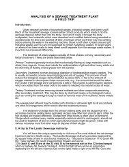
Environmental Setting<br />
1.77 acre commercially developed parcel in<br />
northern New Jersey<br />
Located within the Piedmont Province of New<br />
Jersey<br />
Underlain by the Passaic formation<br />
Reddish/brown to brownish/purple <strong>and</strong> grayish/red shale,<br />
siltstone, mudstone, s<strong>and</strong>stone, <strong>and</strong> conglomerates<br />
Unconsolidated sediments are stratified <strong>and</strong> unstratified<br />
glacial till ranging from fine clays <strong>and</strong> silts to gravel <strong>and</strong><br />
boulders<br />
Onsite soils have been classified as “Urban<br />
l<strong>and</strong>” by the USDA SCS
Site investigations completed previously<br />
by other consulting engineering firms<br />
Draft ASTM Phase I ESA Report (April 2004)<br />
Geotechnical Engineering Report (April 2004)<br />
Revised Hazardous Materials Investigation<br />
report (July 2004)<br />
Limited Phase II Site Investigation (dated July<br />
2004)<br />
<strong>The</strong> Phase I identified several recognized areas<br />
of environmental concern (RECs) <strong>and</strong> areas of<br />
concern (AOCs)<br />
Stained soils were encountered during<br />
geotechnical investigations<br />
Further investigation revealed the following:<br />
One (1) 3,000-gallon diesel underground storage tank<br />
(UST) <strong>and</strong> one (1) 2,000-gallon gasoline UST were<br />
removed in 1992<br />
<strong>The</strong> NJDEP issued a No Further Action (NFA) letter for this<br />
AOC on September 30, 1994. Residual soil impact<br />
associated with this AOC may remain at the site based on<br />
the results of the previous geotechnical borings<br />
One (1) 550-gallon fuel oil UST located on the north<br />
side of Building #1 was ab<strong>and</strong>oned in place in 1992
Onsite contamination was discovered<br />
during routine groundwater sampling<br />
Chlorinated groundwater was attributed to an<br />
offsite source<br />
Former chemical company located upgradient<br />
Site is currently being investigated<br />
<strong>Hydrocarbon</strong> impact in MW-3 could not be<br />
definitively attributed to the former gasoline<br />
<strong>and</strong> diesel USTs<br />
<strong>The</strong> NJDEP granted a NFA for the area<br />
Limited soil laboratory analysis confirmed<br />
the presence of hydrocarbons<br />
Concentrations were below the NJDEP<br />
IGWSCC<br />
Samples were not collected according to<br />
the NJAC 7:26E Technical Requirements<br />
for Site Remediation or the NJDEP Field<br />
Sampling Procedures Manual<br />
Vertical <strong>and</strong> horizontal delineation of impacted<br />
soils was not completed!!
Current Remedial Investigations<br />
Pennoni Associates, Inc. is the current<br />
environmental consultant on the project<br />
Soil borings <strong>and</strong> sampling<br />
Routine groundwater sampling<br />
Separate Phase Product (SPP) in MW-3!<br />
Installation of 2 additional monitoring wells<br />
MALM to delineate the plume<br />
More soil <strong>and</strong> groundwater sampling…<br />
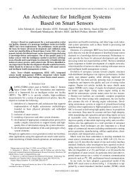
AREA OF<br />
SUSPECTED IMPACT
MALM <strong>Plume</strong> Delineation<br />
Pennoni subcontracted out for the MALM<br />
Contracted firm specializes exclusively in nonintrusive,<br />
non-destructive geophysics<br />
Privately owned woman business enterprise<br />
<strong>The</strong> MALM survey was conducted in the<br />
vicinity of MW-3<br />
MALM Survey Setup
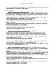
MALM Survey In Action<br />
Boreholes drilled radially around MW-3<br />
Electrodes inserted <strong>and</strong> connected to<br />
resistivity meter<br />
Water is poured into boreholes<br />
Current turned on <strong>and</strong> resistivities<br />
measured<br />
Electrode Array
MALM<br />
Measurements are downloaded<br />
GPS points are taken for reference<br />
Pennoni supplied subcontractor with base<br />
plan of existing site conditions<br />
Contours of variations in resistivity were<br />
calculated <strong>and</strong> plotted<br />
MALM Results
Additional Sampling<br />
Soil borings were completed along<br />
measured plume boundaries<br />
Confirm horizontal boundary of plume<br />
Determine location of soil impact that falls<br />
below IGWSCC<br />
Present remedial options to client<br />
Conclusions<br />
MALM is an old technology that is being<br />
used in new areas<br />
Mathematics are used to calculate the<br />
boundaries of subsurface contaminant<br />
plumes based on electrical resistivity<br />
MALM is an effective, non-intrusive<br />
geophysical method to determine the<br />
presence <strong>and</strong> boundaries of SPP in<br />
subsurface soils
Selected References<br />
Osiensky, J.L., P.R. Donaldson (1995), “Electrical flow through an<br />
aquifer for contaminant source leak detection <strong>and</strong> delineation of<br />
plume evolution”, Journal of Hydrology, v. 169, pp. 243-263.<br />
J.L. Osiensky (1997), “Ground water modeling of mise-a-la-masse<br />
delineation of contaminated ground water plumes”, Journal of<br />
Hydrology, v. 197, pp. 146-165.<br />
United States Army Corps of Engineers (1995), “Engineering <strong>and</strong><br />
Design: Geophysical Exploration for Engineering <strong>and</strong> Environmental<br />
Investigations<br />
Pennoni Associates, Inc. (2004), “Remedial Investigation Report”<br />
Enviroscan, Inc. (2004), www.enviroscan.com<br />
QUESTIONS?