Time-Interleaved Digital-to-Analog Converters for ... - FTW User Server
Time-Interleaved Digital-to-Analog Converters for ... - FTW User Server
Time-Interleaved Digital-to-Analog Converters for ... - FTW User Server

Create successful ePaper yourself
Turn your PDF publications into a flip-book with our unique Google optimized e-Paper software.
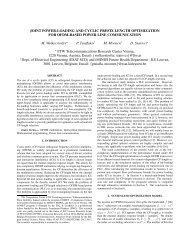
<strong>Time</strong>-<strong>Interleaved</strong> <strong>Digital</strong>-<strong>to</strong>-<strong>Analog</strong> <strong>Converters</strong> <strong>for</strong><br />
UWB Signal Generation<br />
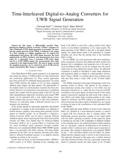
Abstract-In this paper, a differentially encoded <strong>Time</strong><br />
<strong>Interleaved</strong> <strong>Digital</strong>-<strong>to</strong>-<strong>Analog</strong> Converter (TIDAC) structure <strong>for</strong><br />
Ultra-Wideband (UWB) signal generation is presented. We show<br />
that the output spectrum of the TIDAC is identical <strong>to</strong> the output<br />
of a DAC running at a higher sampling rate. To support the<br />
mathematical derivations, the UWB signal genera<strong>to</strong>r has been<br />
implemented on FPGA hardware and measurements have been<br />
taken <strong>for</strong> a sinusoidal wave, a Gaussian UWB pulse shape<br />
and <strong>for</strong> a UWB OFDM signal. The measurements show that,<br />
compared <strong>to</strong> the single-channel DAC, the mirror images around<br />
the sampling frequency can be reduced by about 30 dB and the<br />
analog interpolation filter design is simplified.<br />
I. INTRODUCTION<br />
Ultra Wide-Band (UWB) signal generation is an important<br />
task within the design of UWB systems <strong>for</strong> data transmission<br />
and positioning applications [1]. Thus, several approaches<br />
have been proposed <strong>for</strong> wideband signal generation. For pulse<br />
based UWB systems, the authors in [2], [3] have compared<br />
different pulse shapes and their spectra. The applicability of<br />
the studied pulses <strong>for</strong> communication scenarios has been presented.<br />
However, most important is the generation of wideband<br />
signals that comply with the spectral mask of the FCC [4] and<br />
other standardization authorities. Generally, pulse based UWB<br />
signals can be generated with a very simple analog circuit,<br />
which contains step recovery diodes or other active elements.<br />
However, <strong>for</strong> each pulse shape a different circuitry has <strong>to</strong> be<br />
designed and optimized.<br />
If the system should be universally applicable and flexible<br />
in adaptation <strong>to</strong> changes in the environment (e.g. adapting <strong>to</strong><br />
mutual antenna coupling), then analog pulse genera<strong>to</strong>r circuits<br />
appear not flexible enough. As an alternative, a <strong>Digital</strong>-<strong>to</strong><br />
<strong>Analog</strong> Converter (DAC) can be used <strong>to</strong> generate different<br />
wideband signals. Since technological limits have been pushed<br />
recently (<strong>for</strong> DACs even further than <strong>for</strong> <strong>Analog</strong>-<strong>to</strong>-<strong>Digital</strong><br />
<strong>Converters</strong> (ADCs)) up <strong>to</strong> several GSafs of conversion rate<br />
[5], direct broadband signal generation becomes feasible.<br />
Moreover, the standardized Multi Band (MB)-OFDM signals<br />
have <strong>to</strong> be generated with DACs anyway. The pulse shapes<br />
generated by the DAC can be arbitrary, allowing quick adaptation<br />
<strong>to</strong> different broadband systems, or an adaptive antenna<br />
matching according <strong>to</strong> the scenario.<br />
In this work we focus on time-interleaved DACs (TIDACs)<br />
which consist of M DACs operating at low sampling rate.<br />
1-4244-0521-1/07/$20.00 ©2007 IEEE<br />
Chris<strong>to</strong>ph Krall 1,2 , Christian Voge1 2 , Klaus Witrisa1 2<br />
lChristian Doppler Labora<strong>to</strong>ry <strong>for</strong> Nonlinear Signal Processing<br />
2 Signal Processing and Speech Communication Labora<strong>to</strong>ry<br />
Graz University of Technology<br />
Inffeldgasse 1211, Graz, Austria<br />
{chris<strong>to</strong>ph.krall, vogel, witrisal}@tugraz.at<br />
366<br />
Each of the DACs is used with a phase shifted clock which<br />
results in time-shifted contribution <strong>to</strong> the output signal. The<br />
main advantage of the TIDAC is that due <strong>to</strong> the phase shifted<br />
signals, the output signal seems <strong>to</strong> be generated at a higher<br />
sampling rate, given that the settling time of the individual<br />
DACs is high.<br />
For the TIDAC, the clock generation adds more implementation<br />
complexity. However, this additional ef<strong>for</strong>t remains low<br />
because only a multi phase clock genera<strong>to</strong>r has <strong>to</strong> be used <strong>to</strong><br />
clock the different DACs. For the two channel case, this can be<br />
easily done by using differential signals. Hence, the additional<br />
complexity is traded <strong>for</strong> flexibility in pulse shape adaptation<br />
and generation which is needed in a demonstration environment.<br />
Using a TIDAC on a mobile device may consume more<br />
chip area than using a single DAC at the M -times higher<br />
speed.<br />
The TIDAC proposed in this paper distinguishes itself from<br />
previous works as follows. The authors in [6] consider a<br />
time-interleaved scheme that consists of two DACs that are<br />
alternately switched on, i.e., either the first or the second DAC<br />
contributes <strong>to</strong> the output signal. An improvement <strong>for</strong> the output<br />
signal is achieved by mapping the data words with a return <strong>to</strong><br />
zero (RTZ) code which helps avoiding glitches in the output<br />
signal [7]. However, this RTZ coding is not applicable <strong>to</strong> our<br />
structure because the output signal combination in our scheme<br />
is always the sum of the contributions of the individual DACs<br />
in the TIDAC.<br />
Another approach using TIDACs is shown in [8], where the<br />
DACs are operated in a time-interleaved manner <strong>to</strong> achieve<br />
a signal with less dis<strong>to</strong>rtions due <strong>to</strong> aliasing effects. The<br />
interleaving structure generates samples of the output signal<br />
with four DACs operating in parallel. At the output the signal<br />
is summed up and due <strong>to</strong> the overlapping of different samples<br />
at low sampling rate in one sampling instance at high sampling<br />
rate, an "averaging" (without normalization by the number of<br />
samples) effect is achieved and a similar signal is generated at<br />
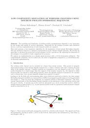
the output. This scheme is depicted <strong>for</strong> a two-channel TIDAC<br />
in Fig. 1. The individual signals from the DACs are phaseshifted<br />
and the summed output is shown in the lowest picture.<br />
The approach discussed in this paper uses a similar structure<br />
with time-interleaved DACs, but uses a precoding scheme that<br />
allows <strong>to</strong> generate exactly the same signal on an M -times
[7] R. Adams and K. Nguyen, "A 113-dB SNR Oversampling DAC with<br />
Segmented Noise-Shaped Scrambling," IEEE 1. Solid-State Circuits,<br />
vol. 33, no. 12, pp. 1871-1878, 1998.<br />
[8] A. G. Venes, K. L. Miller, and P. Vorenkamp, "Method and System <strong>for</strong><br />
<strong>Time</strong> <strong>Interleaved</strong> <strong>Digital</strong> <strong>to</strong> <strong>Analog</strong> Conversion <strong>for</strong> a Cable Modem,"<br />
u.S. Patent US 2006/0098823 AI, May, 2006.<br />
[9] A. V. Oppenheim and R. W. Schafer, Discrete-<strong>Time</strong> Signal Processing,<br />
2nd ed. Prentice Hall Inc., 1998.<br />
371<br />
[10] Xilinx, "Virtex-4 ML403 Embedded Plat<strong>for</strong>m," Xilinx Inc., Tech. Rep.,<br />
May 2006. [Online]. Available: hUp:llwww.xilinx.comlml403<br />
[11] "Stan<strong>for</strong>d Research Systems CG635 Synthesized<br />
Clock Genera<strong>to</strong>r," 2006. [Online]. Available:<br />
hUp:llwww.thinksrs.comlproducts/CG635.htm<br />
[12] ECMA, ECMA-368: High Rate Ultra Widebarul PHY and MAC<br />
Standard. Geneva, Switzerland: ECMA (European Association <strong>for</strong><br />
Standardizing In<strong>for</strong>mation and Communication Systems), Jun. 2005.<br />
[Online]. Available: hUp:llwww.ecma.chlecmal/STAND/ecma-368.htm