Elasticity modulus, hardness and fracture toughness of Ni3Sn4 ...
Elasticity modulus, hardness and fracture toughness of Ni3Sn4 ...
Elasticity modulus, hardness and fracture toughness of Ni3Sn4 ...

Create successful ePaper yourself
Turn your PDF publications into a flip-book with our unique Google optimized e-Paper software.
Abstract<br />
Materials Science <strong>and</strong> Engineering A 423 (2006) 107–110<br />
<strong>Elasticity</strong> <strong>modulus</strong>, <strong>hardness</strong> <strong>and</strong> <strong>fracture</strong> <strong>toughness</strong><br />
<strong>of</strong> <strong>Ni3Sn4</strong> intermetallic thin films<br />
Zhong Chen a,∗ , Min He a , Bavani Balakrisnan b , Chan Choy Chum b<br />
a School <strong>of</strong> Materials Science <strong>and</strong> Engineering, Nanyang Technological University, 50 Nanyang Avenue, Singapore 639798, Singapore<br />
b Institute <strong>of</strong> Materials Research <strong>and</strong> Engineering, 3 Research Link, Singapore 117602, Singapore<br />
Received 8 July 2005; received in revised form 1 December 2005; accepted 6 December 2005<br />
Intermetallic compounds (IMCs) are present in microelectronic solder interconnects as a result <strong>of</strong> interfacial reaction between the solder <strong>and</strong> the<br />
metallization materials. Their mechanical properties are <strong>of</strong> great interest for the prediction <strong>of</strong> joint reliability <strong>of</strong> electronic packages. In this work,<br />
thin film <strong>Ni3Sn4</strong> IMCs were formed by co-sputtering <strong>of</strong> Sn <strong>and</strong> Ni, followed by annealing at different temperatures. <strong>Elasticity</strong> <strong>modulus</strong> <strong>and</strong> <strong>hardness</strong><br />
<strong>of</strong> the films were investigated by nano-indentation. It was found that measured <strong>hardness</strong> decreased with increasing residual tensile stress in the film.<br />
The elasticity <strong>modulus</strong> <strong>of</strong> the <strong>Ni3Sn4</strong> thin films was measured to be around 134 GPa by nano-indentation. The <strong>fracture</strong> <strong>toughness</strong> <strong>of</strong> these <strong>Ni3Sn4</strong><br />
thin films varied considerably with the annealing temperature. It ranged from 2.11 ± 0.15 MPa m 1/2 for 100 ◦ C annealing to 5.75 ± 0.25 MPa m 1/2<br />
for 200 ◦ C annealing. Densification during annealing is believed to be the cause <strong>of</strong> the increase in <strong>toughness</strong>.<br />
© 2006 Elsevier B.V. All rights reserved.<br />
Keywords: Thin film; Intermetallic compound; Fracture <strong>toughness</strong>; <strong>Elasticity</strong> <strong>modulus</strong>; Indentation <strong>hardness</strong><br />
1. Introduction<br />
Solder joints provide electrical connection, mechanical support<br />
<strong>and</strong> thermal dissipation routes for microelectronic devices.<br />
An important constituent <strong>of</strong> a solder joint is the intermetallic<br />
compound (IMC), which is formed between the solder <strong>and</strong><br />
metallization pads during soldering. The physical properties <strong>of</strong><br />
IMCs, including elasticity <strong>modulus</strong>, <strong>hardness</strong>, <strong>fracture</strong> <strong>toughness</strong>,<br />
coefficient <strong>of</strong> thermal expansion, thermal conductivity <strong>and</strong><br />
heat capacity have been focus <strong>of</strong> numerous research efforts<br />
[1–10]. As the down-scaling <strong>of</strong> feature sizes <strong>of</strong> microelectronic<br />
devices continues, the volume fraction <strong>of</strong> the IMC in a solder<br />
joint will increase further, making it an indispensable component<br />
to be considered in determining the device performance <strong>and</strong> reliability.<br />
In the past, work on IMCs in electronic packaging was<br />
mainly focused on Cu–Sn system (Cu6Sn5, Cu3Sn) because <strong>of</strong><br />
the predominant use <strong>of</strong> Cu as metallization material [11]. With<br />
the wide-spread use <strong>of</strong> lead-free solders in recent years, there<br />
is an increasing concern about the reliability <strong>of</strong> packages with<br />
Cu metallization. This is because that most <strong>of</strong> the popular lead-<br />
∗ Corresponding author. Tel.: +65 67904256; fax: +65 67909081.<br />
E-mail address: aszchen@ntu.edu.sg (Z. Chen).<br />
0921-5093/$ – see front matter © 2006 Elsevier B.V. All rights reserved.<br />
doi:10.1016/j.msea.2005.12.038<br />
free solders contain higher percentage <strong>of</strong> Sn <strong>and</strong> their melting<br />
temperatures are usually 30–40 ◦ C higher than eutectic Sn–Pb<br />
solder [12–14]. Both these factors contribute to faster solder<br />
reaction with Cu forming a thicker IMC layer, which may eventually<br />
cause solder joint failure due to the brittleness <strong>of</strong> the layer.<br />
However, Ni based metallization have slower rate <strong>of</strong> reaction<br />
compared to Cu [12], <strong>and</strong> therefore extensive research has been<br />
carried out in recent years on the interaction between various<br />
types <strong>of</strong> solders <strong>and</strong> Ni-based metallization [15–23]. Therefore<br />
investigating the mechanical properties <strong>of</strong> the IMCs formed with<br />
Ni-based metallization is crucial.<br />
Existing data on IMC properties were mainly obtained from<br />
measurements on bulk samples, prepared either by powder metallurgy<br />
[2] or by casting [4]. However, there is no established<br />
method to measure thin film IMC <strong>fracture</strong> <strong>toughness</strong>. The only<br />
work that has been reported is our early work on <strong>fracture</strong> <strong>toughness</strong><br />
<strong>of</strong> thin films <strong>of</strong> co-sputtered Cu–Sn IMCs using controlled<br />
buckling test [10]. This technique has several advantages compared<br />
to the indentation technique typically used on bulk specimens.<br />
Firstly, the grain size <strong>and</strong> the thickness <strong>of</strong> thin films are<br />
closer to the one in real electronic packages where the IMC<br />
thickness is at the order <strong>of</strong> micron. Moreover, the grain size<br />
in bulk specimens obtained by casting <strong>and</strong> annealing was at<br />
the order <strong>of</strong> tens <strong>of</strong> micron [4]. Secondly, the thin film <strong>fracture</strong>
108 Z. Chen et al. / Materials Science <strong>and</strong> Engineering A 423 (2006) 107–110<br />
<strong>toughness</strong> measurement enjoyed better accuracy <strong>and</strong> narrower<br />
scatter. It was well known that the indentation induced <strong>fracture</strong><br />
experiment has to be interpreted based on some pre-assumed<br />
<strong>fracture</strong> patterns. Accordingly, there are many calibration equations<br />
derived based on various types <strong>of</strong> model. The choice <strong>of</strong><br />
these empirical equations may give rise to the large discrepancy<br />
among reported values. Thirdly, the thin film measurement<br />
presents isotropic “bulk” properties, while the measurement on<br />
large grain sized IMCs may suffer from the uncertainty <strong>of</strong> crystallographic<br />
orientation at the particular point <strong>of</strong> indentation [4].<br />
All these features make the buckling test [10] an attractive alternative<br />
for thin film <strong>fracture</strong> <strong>toughness</strong> measurement. So far there<br />
has not been any report known to us on the <strong>fracture</strong> <strong>toughness</strong><br />
<strong>of</strong> thin film <strong>Ni3Sn4</strong>. On the other h<strong>and</strong>, use <strong>of</strong> co-sputtered<br />
thin film specimens has its own concerns as well. The subsequent<br />
annealing <strong>of</strong> the thin films that have been deposited on a<br />
substrate usually causes in-plane stresses due to densification.<br />
The induced residual stress may affect the measured mechanical<br />
properties. Fortunately residual stress can be superimposed in<br />
the calculation <strong>of</strong> <strong>fracture</strong> <strong>toughness</strong>; therefore the measurement<br />
will not be affected as long as both the film <strong>and</strong> substrate remain<br />
elastic throughout the test. However, the quantitative correction<br />
to <strong>hardness</strong> <strong>and</strong> elasticity <strong>modulus</strong> is not yet established. In this<br />
paper, we report three fundamental mechanical properties, i.e.,<br />
elasticity <strong>modulus</strong>, <strong>hardness</strong> <strong>and</strong> <strong>fracture</strong> <strong>toughness</strong> <strong>of</strong> <strong>Ni3Sn4</strong><br />
thin films. In addition, we also discuss the effect <strong>of</strong> residual<br />
stress induced during annealing on the measured properties.<br />
2. Experiment<br />
Thin metallic films <strong>of</strong> Ni <strong>and</strong> Sn were co-sputtered onto<br />
polyetherimide (Ultem) stripes <strong>and</strong> silicon wafers using a DC<br />
magnetron sputtering machine at room temperature without<br />
intentionally heating the substrates. The dimension <strong>of</strong> the Ultem<br />
stripes was 48 mm × 3mm× 0.175 mm. The glass transition<br />
temperature, elasticity <strong>modulus</strong> <strong>and</strong> Poisson’s ratio <strong>of</strong> the Ultem<br />
substrate are 247 ◦ C, 2.6 GPa <strong>and</strong> 0.36, respectively. The stoichiometic<br />
composition was maintained during co-deposition by<br />
controlling the deposition rates <strong>of</strong> individual targets. In order to<br />
form <strong>Ni3Sn4</strong> IMC, the deposition rate <strong>of</strong> Ni to Sn was maintained<br />
at 3:4 ratio by controlling the sputtering power to the<br />
individual Ni <strong>and</strong> Sn targets (75:70 W). The working pressure<br />
was 5.3 mTorr <strong>and</strong> the Ar flow rate was 25 sccm. After sputtering,<br />
the samples were annealed in inert N2 ambience for 24 h<br />
at 50, 100, 150, 200, 250 <strong>and</strong> 300 ◦ C. The thickness <strong>of</strong> the film<br />
deposited after the annealing was 420 nm, as-measured using<br />
with a surface pr<strong>of</strong>ilometer. X-ray diffraction (XRD) <strong>and</strong> energy<br />
dispersive spectroscopy were used to identify the phase <strong>and</strong> composition<br />
<strong>of</strong> the film, respectively.<br />
Table 1<br />
<strong>Elasticity</strong> <strong>modulus</strong>, <strong>hardness</strong>, residual stress <strong>and</strong> <strong>fracture</strong> <strong>toughness</strong> <strong>of</strong> <strong>Ni3Sn4</strong> thin films<br />
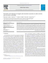
Fig. 1. XRD patterns <strong>of</strong> the <strong>Ni3Sn4</strong> films annealed at different temperatures.<br />
<strong>Elasticity</strong> <strong>modulus</strong> <strong>and</strong> <strong>hardness</strong> were measured using a nanoindenter<br />
(NanoTest TM ) on films deposited on silicon wafers. The<br />
film <strong>fracture</strong> <strong>toughness</strong> was evaluated by the controlled buckling<br />
test using specimens prepared on Ultem substrates. Preliminary<br />
experiments indicated that surface morphology <strong>of</strong> the films on<br />
Ultem stripes <strong>and</strong> Si wafers are similar. The details <strong>of</strong> the buckling<br />
testing were reported elsewhere [24–26]. Seven to nine<br />
specimens were tested for each condition. The residual stress<br />
caused by annealing was calculated by the method published<br />
elsewhere [27].<br />
3. Results <strong>and</strong> discussion<br />
3.1. Phase formation <strong>and</strong> microstructure<br />
Fig. 1 shows the XRD patterns <strong>of</strong> the as-deposited specimen,<br />
together with those annealed at various temperatures.<br />
Composition analysis by EDX confirmed that ratio <strong>of</strong> Ni to<br />
Sn was 3:4. The SEM images in Fig. 2 show the grain size<br />
to be about 100 nm for all the specimens annealed between 100<br />
<strong>and</strong> 200 ◦ C. From the XRD patterns, <strong>Ni3Sn4</strong> compound seem<br />
to be formed even in the as-deposited state, although we could<br />
not tell whether there were any un-reacted Ni <strong>and</strong> Sn from the<br />
XRD result. After annealing for 24 h at 50 ◦ C <strong>and</strong> above, <strong>Ni3Sn4</strong><br />
peaks were sharp <strong>and</strong> clear, indicating complete formation <strong>of</strong> the<br />
compound.<br />
3.2. Hardness, elasticity <strong>modulus</strong> <strong>and</strong> residual stress<br />
Table 1 lists the elasticity <strong>modulus</strong>, <strong>hardness</strong>, residual stress<br />
<strong>and</strong> <strong>fracture</strong> <strong>toughness</strong> <strong>of</strong> <strong>Ni3Sn4</strong> thin films. At 100 ◦ C anneal-<br />
Annealing temperature ( ◦ C) Hardness (GPa) <strong>Elasticity</strong> <strong>modulus</strong> (GPa) Fracture <strong>toughness</strong> (MPa m 1/2 ) Residual stress (MPa)<br />
100 7.0 134.0 2.11 ± 0.15 0<br />
150 6.5 119.4 4.08 ± 0.21 342<br />
200 6.1 123.4 5.75 ± 0.25 564
Fig. 2. SEM images showing the film cracking patterns after the <strong>fracture</strong> <strong>toughness</strong><br />
test. Grains <strong>of</strong> about 100 nm are clearly visible from these pictures. Specimens<br />
are annealed at (a) 100, (b) 150 <strong>and</strong> (c) 200 ◦ C for 24 h.<br />
Z. Chen et al. / Materials Science <strong>and</strong> Engineering A 423 (2006) 107–110 109<br />
ing, the residual stress was very small. Significant tensile stress<br />
has developed after 150 <strong>and</strong> 200 ◦ C annealing, most likely<br />
caused by densification <strong>of</strong> the films. Since the co-deposition is<br />
carried out without substrate heating, the mobility <strong>of</strong> the adatoms<br />
are relatively low, <strong>and</strong> there will inevitably exist some internal<br />
defects, such as vacancies <strong>and</strong> interstitial voids, etc. During<br />
annealing the elimination <strong>of</strong> these defects densifies the film.<br />
However the film is constrained by the substrate so that it cannot<br />
densify by shrinking. As a result, tensile stress in the film<br />
will be induced [27]. Since such a process is thermally activated,<br />
stress can only build up when the temperature is high<br />
enough.<br />
The indentation <strong>hardness</strong> decreased steadily with the increase<br />
<strong>of</strong> annealing temperatures. This was believed to be related to<br />
the tensile stress in the film. Indentation measures the resistance<br />
to compressive intrusion by the indenter tip. Tensile stress<br />
in the film reduces the penetration resistance to the indenter,<br />
<strong>and</strong> thus reduces the measured <strong>hardness</strong>. The elasticity <strong>modulus</strong><br />
fell slightly with the residual stress but it did not seem<br />
to follow the steady trend as the <strong>hardness</strong> did. Our reported<br />
<strong>modulus</strong> at stress-free state (100 ◦ C annealing) agreed very well<br />
with the reported value <strong>of</strong> 133.3 GPa by Fields et al. [2] but<br />
was higher than 118.4 GPa reported by Ghosh [4]. In Ghosh’s<br />
work, the average grain size was 32 m <strong>and</strong> the indentation<br />
was made inside a grain. Therefore the reported value in his<br />
work was an average <strong>of</strong> values from many single grains with<br />
unknown crystallographic orientations. While in our current<br />
work, the grain size was small so that the indentation likely<br />
reflected contribution from multiple grains. We suppose that<br />
the difference could be due to the difference in crystallographic<br />
orientation.<br />
3.3. Fracture <strong>toughness</strong><br />
The <strong>fracture</strong> <strong>toughness</strong> measured is reported in Table 1 with<br />
its st<strong>and</strong>ard deviation. Since our measured elasticity <strong>modulus</strong><br />
was very close to one by Fields et al. [2], the <strong>modulus</strong><br />
(133.3 GPa) <strong>and</strong> Poisson’s ratio (0.33) recommended by Fields<br />
et al. were used in our calculation <strong>of</strong> <strong>fracture</strong> <strong>toughness</strong>. Residual<br />
stress was superimposed on the stress induced by the buckling<br />
test, therefore the influence from the residual stress was well<br />
accounted for. The cracking patterns in Fig. 2 show that the<br />
<strong>fracture</strong> was mainly intergranular, which is similar to the thin<br />
film cracking in Cu–Sn IMCs [10]. It is interesting to note that<br />
the cracks remained open after the release <strong>of</strong> the loading for<br />
the 150 <strong>and</strong> 200 ◦ C annealed specimens. The gap could not be<br />
caused by residual plastic deformation since the film <strong>and</strong> the<br />
substrate remained elastic during the <strong>fracture</strong> test. We believe<br />
it is to due to the release <strong>of</strong> residual tensile stress <strong>of</strong> the film<br />
at the vicinity <strong>of</strong> crack. This view is supported by comparing<br />
Fig. 2(a)–(c): the gap was wider with the 200 ◦ C, which has the<br />
highest residual tensile stress.<br />
There was a considerable increase in <strong>fracture</strong> <strong>toughness</strong> with<br />
annealing temperature from 2.11 ± 0.15 MPa m 1/2 for 100 ◦ C<br />
annealing to 5.75 ± 0.25 MPa m 1/2 for 200 ◦ C annealing. The<br />
scatter in our experiment was smaller than what one would<br />
expect from a conventional <strong>fracture</strong> <strong>of</strong> bulk, brittle materials.
110 Z. Chen et al. / Materials Science <strong>and</strong> Engineering A 423 (2006) 107–110<br />
The increase in <strong>toughness</strong> was, again, due to the densification <strong>of</strong><br />
the film by annealing. Densification reduces the number <strong>of</strong> flaws<br />
<strong>and</strong> the critical flaw size in the film, which improves the <strong>fracture</strong><br />
resistance. Besides the current work, there were only two<br />
reports on the <strong>fracture</strong> <strong>toughness</strong> <strong>of</strong> <strong>Ni3Sn4</strong> that were known<br />
to us, but both are measurements from bulk samples. Ghosh [4]<br />
reported the value to be 4.22 ± 0.45 MPa m 1/2 when the indentation<br />
load was 100 g <strong>and</strong> 3.65 ± 0.47 MPa m 1/2 when the load was<br />
200 g. The values should be compared, if a comparison needs<br />
to be made, with our result <strong>of</strong> 5.75 ± 0.25 MPa m 1/2 obtained<br />
from the 200 ◦ C specimens, because the treatment temperature<br />
is close to the annealing temperature <strong>of</strong> 222 ◦ C used in Ghosh’s<br />
work [4]. Our reported value is clearly higher. The microstructural<br />
difference could be responsible for such a difference. In<br />
our specimens, fine grain sized film <strong>fracture</strong>d by intergranular<br />
mode (Fig. 2). While in the case <strong>of</strong> Ghosh [4], the grain size<br />
was very large (32 m). Under both loads (100 <strong>and</strong> 200 g) the<br />
cracks induced by the indention were mainly contained inside<br />
an individual grain [4]. Both Ghosh’s work <strong>and</strong> our current<br />
work reported much higher values <strong>of</strong> <strong>fracture</strong> <strong>toughness</strong> than<br />
the one by Fields et al. [2], which was 1.2 ± 0.1 MPa m 1/2 . The<br />
specimens used in Fields et al.’s work were prepared by powder<br />
metallurgy. The <strong>fracture</strong> <strong>toughness</strong> <strong>of</strong> sintered specimens is<br />
highly dependent on the porosity; the lower value obtained in<br />
the work <strong>of</strong> Fields et al. [2] could be due to its relatively large<br />
pore size.<br />
4. Conclusion<br />
In this work, <strong>Ni3Sn4</strong> IMC thin films <strong>of</strong> 420 nm thick were<br />
prepared by co-sputtering <strong>and</strong> subsequent annealing. The <strong>hardness</strong><br />
<strong>and</strong> elasticity <strong>modulus</strong> measured by nano-indentation were<br />
7.0 <strong>and</strong> 134 GPa, respectively. Residual stress developed during<br />
annealing affected the measured <strong>hardness</strong> <strong>and</strong> elasticity <strong>modulus</strong>.<br />
Densification <strong>of</strong> the film during annealing significantly<br />
increased the <strong>fracture</strong> <strong>toughness</strong>. The <strong>fracture</strong> <strong>toughness</strong> <strong>of</strong> the<br />
<strong>Ni3Sn4</strong> thin film measured by controlled buckling test was,<br />
respectively, 2.11 ± 0.15, 4.08 ± 0.21 <strong>and</strong> 5.75 ± 0.25 MPa m 1/2<br />
for specimens annealed at 100, 150 <strong>and</strong> 200 ◦ C for 24 h.<br />
References<br />
[1] D.R. Frear, S.N. Burchett, H.S. Morgan, J.H. Lao (Eds.), The Mechanics<br />
<strong>of</strong> Solder Alloy Interconnects, Van Nostr<strong>and</strong> Reinhold, New York, 1994.<br />
[2] R.J. Fields, S.R. Low III, G.K. Lucey Jr., in: M.J. Cieslak, J.H.<br />
Perepezko, S. Kang, M.E. Glicksman (Eds.), The Metal Science <strong>of</strong> Joining,<br />
TMS, Warrendale, PA, 1992, pp. 165–173.<br />
[3] K. Nakajima, A. Isogai, Y. Taga, Jpn. J. Appl. Phys. Suppl. 2 (1974)<br />
309.<br />
[4] G. Ghosh, J. Mater. Res. 19 (2004) 1493.<br />
[5] J.S. Kang, R.A. Gagliano, G. Ghosh, M.E. Fine, J. Electron. Mater. 31<br />
(2002) 1238.<br />
[6] B. Subrahmanyan, Trans. Jpn. Inst. Met. 130 (1972) 93.<br />
[7] R.R. Chromik, R.P. Vinci, S.L. Allen, M.R. Notis, J. Mater. Res. 18<br />
(2003) 2251.<br />
[8] R. Cabarat, L. Guillet, R. LeRoux, J. Inst. Met. 75 (1975) 391.<br />
[9] L.M. Ostrovskaya, V.N. Rodin, A.I. Kuznetsov, Sov. J. Non-Ferrous Met.<br />
26 (1985) 90.<br />
[10] B. Balakrisnan, C.C. Chum, M. Li, Z. Chen, T. Cahyadi, J. Electron.<br />
Mater. 32 (2003) 166.<br />
[11] K.N. Tu, K. Zeng, Mater. Sci. Eng. R34 (2001) 1.<br />
[12] K. Zeng, K.N. Tu, Mater. Sci. Eng. R38 (2002) 55.<br />
[13] A.A. Liu, H.K. Kim, K.N. Tu, J. Appl. Phys. 80 (1996) 2774.<br />
[14] H.K. Kim, K.N. Tu, P.A. Totta, Appl. Phys. Lett. 68 (1996) 2204.<br />
[15] P.L. Liu, J.K. Shang, Metall. Mater. Trans. 31A (2000) 2867.<br />
[16] J.W. Jang, P.G. Kim, K.N. Tu, J. Appl. Phys. 85 (1999) 8456.<br />
[17] K.C. Hung, Y.C. Chan, C.W. Tang, H.C. Ong, J. Mater. Res. 15 (2000)<br />
2534.<br />
[18] P.L. Liu, J.K. Shang, J. Mater. Res. 15 (2000) 2347.<br />
[19] J.W. Jang, D.R. Peter, T.Y. Lee, K.N. Tu, J. Appl. Phys. 88 (2000) 6359.<br />
[20] M. He, Z. Chen, G. Qi, Acta Mater. 52 (2004) 2047.<br />
[21] Z. Chen, M. He, G. Qi, J. Electron. Mater. 33 (2004) 1465.<br />
[22] A. Kumar, M. He, Z. Chen, Surf. Coat. Technol. 198 (2005) 283.<br />
[23] M. He, Z. Chen, G.J. Qi, Metall. Mater. Trans. 36A (2005) 65.<br />
[24] B. Cotterell, Z. Chen, Int. J. Fract. 104 (2000) 169.<br />
[25] Z. Chen, B. Cotterell, W. Wang, E. Guenther, S.J. Chua, Thin Solid<br />
Films 394 (2001) 202.<br />
[26] Z. Chen, B. Cotterell, W. Wang, Eng. Fract. Mech. 69 (2002) 597.<br />
[27] Z. Chen, X. Xu, C.C. Wong, S. Mhaisalkar, Surf. Coat. Technol. 167<br />
(2003) 170.