Improved mechanical and thermomechanical properties of alumina ...
Improved mechanical and thermomechanical properties of alumina ...
Improved mechanical and thermomechanical properties of alumina ...

Create successful ePaper yourself
Turn your PDF publications into a flip-book with our unique Google optimized e-Paper software.
Available online at www.sciencedirect.com<br />
Scripta Materialia 68 (2013) 869–872<br />
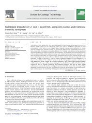
<strong>Improved</strong> <strong>mechanical</strong> <strong>and</strong> thermo<strong>mechanical</strong> <strong>properties</strong> <strong>of</strong> <strong>alumina</strong><br />
substrate via iron doping<br />
Riko. I Made, a,⇑ Eric Jian Rong Phua, a,b Stevin Snellius Pramana, a,c Chee Cheong Wong, a<br />
Zhong Chen, a Alfred Iing Yoong Tok a <strong>and</strong> Chee Lip Gan a,⇑<br />
a School <strong>of</strong> Materials Science <strong>and</strong> Engineering, Nanyang Technological University, 50 Nanyang Avenue, Singapore 639798, Singapore<br />
b Institute <strong>of</strong> Microelectronics, Agency for Science, Technology <strong>and</strong> Research (A * STAR), 11 Science Park Road,<br />
Singapore Science Park II, Singapore 117685, Singapore<br />
c Facility for Analysis, Characterization, Testing <strong>and</strong> Simulation, Nanyang Technological University, 50 Nanyang Avenue,<br />
Singapore 639798, Singapore<br />
Received 25 October 2012; accepted 8 February 2013<br />
Available online 21 February 2013<br />
We present a method to improve the overall <strong>properties</strong> <strong>of</strong> sintered <strong>alumina</strong> substrate via iron doping that has a higher fracture<br />
toughness, lower thermal conductivity, lower thermal expansion coefficient <strong>and</strong> comparable dielectric constant than pure <strong>alumina</strong>.<br />
Such <strong>properties</strong> are beneficial for harsh environment electronic packages. X-ray <strong>and</strong> electron probe microanalyses concluded that<br />
toughening is likely caused by multiple phase strengthening <strong>and</strong> ruled out crack bridging or grain boundary strengthening.<br />
Ó 2013 Acta Materialia Inc. Published by Elsevier Ltd. All rights reserved.<br />
Keywords: Ceramics; High temperature; Harsh environment; Electronics packaging; High pressure<br />
Harsh environment applications typically use<br />
low power devices that do not generate much heat to<br />
be dissipated to the environment. On the contrary, it is<br />
necessary to prevent heat transfer from the environment<br />
to the device chip. For this purpose, a low thermal conductivity<br />
substrate is most suitable.<br />
In this study, Al 2O 3 is selected mainly due to its low<br />
thermal conductivity, suitable electrical conducting<br />
<strong>properties</strong> <strong>and</strong> chemical stability at high temperature;<br />
it also has a particularly mature technology <strong>and</strong> is inexpensive<br />
to produce or acquire. However, it has a relatively<br />
high dielectric constant <strong>and</strong> high coefficient <strong>of</strong><br />
thermal expansion (CTE) than Si, which may impose<br />
some reliability concerns.<br />
Iron has been identified as a possible dopant for <strong>alumina</strong><br />
substrates for such an application. Fe doping has<br />
been reported to decrease the transformation temperature<br />
<strong>of</strong> the amorphous <strong>alumina</strong> g phase to the crystalline<br />
a <strong>alumina</strong> [1], to possibly improve <strong>alumina</strong>–metal adhesion<br />
[2] <strong>and</strong> to improve the <strong>alumina</strong>’s fracture toughness<br />
by means <strong>of</strong> a crack-bridging mechanism due to the<br />
presence <strong>of</strong> a ductile iron phase [1,3–5]. However, the<br />
⇑ Corresponding authors.Tel.: +65 6790 5909 (Chee Lip Gan); e-mail<br />
addresses: imaderiko@ntu.edu.sg; clgan@ntu.edu.sg<br />
presence <strong>of</strong> a ductile iron phase may compromise the<br />
substrate’s electrical insulating <strong>properties</strong>. On the other<br />
h<strong>and</strong>, having fully oxidized Fe may not lead to strengthening<br />
by a crack-bridging mechanism but may deteriorate<br />
the <strong>alumina</strong>’s <strong>mechanical</strong> <strong>properties</strong>. In this work,<br />
we present systematical characterizations <strong>of</strong> the iron<br />
doped <strong>alumina</strong> substrate produced by powder methods.<br />
A mixture <strong>of</strong> <strong>alumina</strong> with 10 wt.% iron (Fe) was prepared<br />
by wet ball milling in an <strong>alumina</strong> jar for 24 h with<br />
a 20:1 weight ratio <strong>of</strong> ball to powder. The resulting powder<br />
was uniaxially pressed to form pellets, followed by<br />
200 MPa cold isostatic pressing. The resulting pellets<br />
were air sintered at 1500 °C for 12 h.<br />
Te fracture toughness <strong>of</strong> the sample was deduced<br />
from the crack length measurement from Vickers indentation<br />
based on the following relation [6]:<br />
Kc ¼ n R<br />
m ðE=HÞ1=2ðP=c 3=2<br />
o Þ ð1Þ<br />
where P is the indentation peak load, co is the crack<br />
length, n R<br />
m ¼ 0:016 0:004 is a material-independent<br />
constant for Vickers-produced radial cracks [6], E is<br />
the Young’s modulus <strong>and</strong> H is the materials hardness,<br />
defined as<br />
H ¼ P=aoa 2<br />
1359-6462/$ - see front matter Ó 2013 Acta Materialia Inc. Published by Elsevier Ltd. All rights reserved.<br />
http://dx.doi.org/10.1016/j.scriptamat.2013.02.032<br />
www.elsevier.com/locate/scriptamat<br />
ð2Þ
870 Riko. I Made et al. / Scripta Materialia 68 (2013) 869–872<br />
where a is the half diagonal <strong>of</strong> the indentation length<br />
<strong>and</strong> ao = 2 is a numerical constant for the Vickers indenter.<br />
Sintered samples were indented with a Vicker’s pyramid-shaped<br />
tip microindenter with 10 kgf load setting<br />
for 10 s dwell time. Commercially purchased sintered<br />
<strong>alumina</strong> samples from Xellatech Pte. Ltd. were also<br />
measured <strong>and</strong> used as a reference.<br />
The thermal conductivity <strong>of</strong> the sintered sample was<br />
deduced from the thermal diffusivity measurement by<br />
the laser flash method. The thermal diffusivity was indirectly<br />
measured by observing the temperature changes<br />
on the front side <strong>of</strong> the sample by laser illumination<br />
from the back <strong>of</strong> the sample. Thus, the thermal conductivity<br />
was obtained by the following relation [7]:<br />
k ¼ aqC ð3Þ<br />
where a is the thermal diffusivity, q is the density <strong>and</strong> C<br />
is the specific heat <strong>of</strong> the specimen.<br />
The thermal expansion coefficient was deduced from<br />
measured linear dimensions change with respect to<br />
increasing heating (5 °C min 1 ) from 20 to 400 °C.<br />
Dielectric constant was obtained from impedance measurement<br />
<strong>of</strong> sintered samples at 1 MHz frequency using<br />
Agilent 4284 A LCR-Meter.<br />
Powder X-ray diffraction (XRD) using a Bruker D8<br />
Advance diffractometer with Cu Ka radiation was used<br />
for phase analysis <strong>of</strong> ball milled <strong>and</strong> sintered samples.<br />
Rietveld refinements [8] were performed for phase quantification<br />
from XRD diffraction patterns. The weight<br />
percentage <strong>of</strong> each phase was calculated based on:<br />
wa ¼ SaðZMV Þa P<br />
iSiðZMV ð4Þ<br />
Þi where wa is the weight fraction <strong>of</strong> phase a, S is the<br />
Rietveld scale factor, Z is the number <strong>of</strong> formula units<br />
in a unit cell, M is the molecular mass <strong>of</strong> the formula<br />
unit <strong>and</strong> V is the unit cell volume [9].<br />
Field emission electron microscopy (FEI Nova 600i<br />
(Nanolab), operating at 5 kV) was used to observe the<br />
morphology <strong>of</strong> the samples. The samples were mirrorpolished<br />
<strong>and</strong> carbon coated before the electron probe<br />
microanalysis (EPMA) was performed on a JEOL<br />
JXA-8530F instrument equipped with five wavelengthdispersive<br />
spectrometers. The accelerating voltage <strong>and</strong><br />
current used were 15 kV <strong>and</strong> 20 nA, respectively.<br />
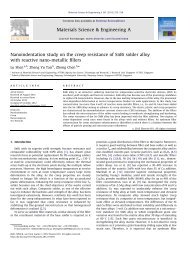
Comparisons <strong>of</strong> particle size between as purchased<br />
<strong>alumina</strong>, iron powder <strong>and</strong> post-ball-milling <strong>alumina</strong><br />
with 10 wt.% Fe are given in Figure 1(a)–(c), respectively.<br />
It can clearly be seen from the secondary electron<br />
microscope imaging that ball milling effectively reduces<br />
the particle size <strong>of</strong> the mixed powder.<br />
Figure 1. Comparison <strong>of</strong> material particle sizes: (a) raw <strong>alumina</strong><br />
powder, (b) iron powder, (c) ball-milled mixture <strong>of</strong> <strong>alumina</strong> <strong>and</strong> iron<br />
powder.<br />
It was found that Fe-doped samples have a higher<br />
fracture toughness (6.12 ± 1.23 MPa m 0.5 ) than undoped<br />
reference samples (3.14 ± 0.88 MPa m 0.5 ). The<br />
measured absolute density <strong>of</strong> the doped samples was<br />
higher (3.83 ± 0.02 g cm 3 ) than the reference sample<br />
(3.64 ± 0.22 g cm 3 ), but both samples have similar relative<br />
mass density with respect to their theoretical mixture’s<br />
density <strong>of</strong> 10 wt.% Fe (4.05 g cm 3 ) <strong>and</strong> 0 wt.% Fe<br />
(4.00 g cm 3 ) for the doped <strong>and</strong> reference sample,<br />
respectively.<br />
The doped samples also show a lower thermal diffusivity<br />
than the reference sample, i.e. 5.11 ± 0.04 <strong>and</strong><br />
8.14 ± 0.09 mm 2 s 1 , respectively. From differential<br />
scanning calorimetry heating <strong>and</strong> cooling curves, both<br />
samples have a heat capacity <strong>of</strong> 0.765 J g 1 K 1 at<br />
25 °C. Thus, from Eq. (3) we determined that there is<br />
a reduction in the thermal conductivity <strong>of</strong> the doped<br />
samples from 22.43 ± 0.29 to 16.16 ± 1.91 W m 1 K 1 .<br />
The doped samples show a CTE reduction from<br />
8.40 ± 0.017 to 6.91 ± 0.048 ppm K 1 . On the other<br />
h<strong>and</strong>, the relative dielectric constant is higher for the<br />
doped samples than for the reference sample<br />
(10.36 ± 0.241 as compared to 9.9 ± 0.018).<br />
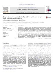
XRD characterization <strong>of</strong> the as-prepared powder,<br />
reference <strong>and</strong> sintered samples are given in Figure<br />
2(a)–(c), respectively. Rietveld refinement <strong>of</strong> the<br />
as-prepared powder shows that around 2.4 ± 0.1 wt.%<br />
crystalline Fe remains in the form <strong>of</strong> iron metal, hematite<br />
(Fe 2O 3)<strong>and</strong>wüstite (FeO) from the 10 wt.% Fe initially<br />
added. This reduction in the detected quantity <strong>of</strong><br />
Fe can be attributed to both the formation <strong>of</strong> amorphous<br />
Fe <strong>and</strong> the addition <strong>of</strong> <strong>alumina</strong>. The source <strong>of</strong> extra<br />
<strong>alumina</strong> could come from erosion debris <strong>of</strong> the ball<br />
milling’s jar, as well as from the <strong>alumina</strong> ball during<br />
the ball-milling process. Rietveld refinement also indicated<br />
that the average grain size from the integrated<br />
breadth volume weighted mean column lengths [10]<br />
(LVol-IB) is 50 ± 8 nm.<br />
On the other h<strong>and</strong>, the full width at half maximum<br />
observed from the XRD patterns <strong>of</strong> both the reference<br />
sample <strong>and</strong> the sintered samples is narrower than the<br />
Figure 2. XRD <strong>of</strong> the ball-milled powder, reference sample <strong>and</strong><br />
sintered sample. (a) Ball-milled powder, consisting <strong>of</strong> a mixture <strong>of</strong><br />
Al2O3, FeO <strong>and</strong> Fe2O3. After ball milling, only 2.4 ± 0.1 wt.% Fe is in<br />
the mixture. (b) Reference sample, with 0.4 wt.% MgO (i.e. trace). (c)<br />
Sintered pellet, with 2.30 ± 0.04 at.% Fe in Fe 3+ found to substitute<br />
Al 3+ , equivalent to 2.5 wt.% Fe.
as-prepared powder XRD pattern. The reference sample<br />
shows it consists mostly <strong>of</strong> <strong>alumina</strong> with an average<br />
grain-size (LVol-IB) <strong>of</strong> 128 ± 11 nm, with 0.4 wt.%<br />
<strong>of</strong> MgO impurity, which is arguably beyond the XRD<br />
detection limit.<br />
All hkl reflections can be identified as corundum<br />
Al2O3 phase, with an LVol-IB <strong>of</strong> 122 ± 10 nm, which<br />
is larger than the 50 ± 8 nm <strong>of</strong> the unsintered powders.<br />
Neither crystalline Fe(body-centered cubic, bcc) nor<br />
other oxidized Fe was observed. The absence <strong>of</strong> Fe metal<br />
thus implies that the increase in fracture toughness is<br />
not caused by a crack-bridging mechanism. Further<br />
refinement shows that 2.5 wt.% Fe (2.30 ± 0.04 at.%)<br />
has substituted for Al 3+ . This substitution has exp<strong>and</strong>ed<br />
the unit cell, with the lattice parameters changing from<br />
a = 4.7591 A ˚ <strong>and</strong> c = 12.9973 A ˚ to a = 4.7735 ±<br />
8.8 10 4 A ˚ <strong>and</strong> c = 13.0293 ± 3.8 10 4 A ˚ . No preferred<br />
orientation, which may suggest abnormal grain<br />
growth, was observed from the refinement. This result<br />
indicates that most <strong>of</strong> the available Fe has been oxidized<br />
to Fe 3+ during sintering. The fact that Fe 3+ is preferred<br />
over Fe 2+ is due to the ionic radius <strong>of</strong> Fe 3+<br />
(r Fe 3þ = 0.49 A ˚ ) being closer to that <strong>of</strong> Al 3+<br />
(r Al 3þ = 0.39 A ˚ ) than the larger Fe 2+ (r Al 3þ = 0.63 A ˚ )<br />
[11], <strong>and</strong> the oxygen site is fully occupied within the estimated<br />
st<strong>and</strong>ard deviation. The amorphization <strong>of</strong> the<br />
iron by ball milling was suspected to be negligible,<br />
although further verifications are still needed.<br />
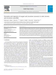
Backscattered electron (BSE) imaging coupled with<br />
EPMA was used for the compositional analysis. It reveals<br />
that the doped samples consist <strong>of</strong> three distinct<br />
phases, as shown in Figure 3(a), labeled as a, b <strong>and</strong> c,<br />
respectively. The first <strong>and</strong> darkest phase, a, consists <strong>of</strong><br />
around 99.49 ± 0.01 wt.% <strong>alumina</strong> <strong>and</strong> 0.49 ±<br />
0.01 wt.% Fe2O3. The second phase, b, with a brighter<br />
appearance, consists <strong>of</strong> 95.02 ± 0.18 wt.% <strong>alumina</strong> <strong>and</strong><br />
4.95 ± 0.18 wt.% Fe2O3. Finally, the third phase, c, appears<br />
the brightest, <strong>and</strong> consists <strong>of</strong> 59.47 ± 0.76 wt.%<br />
<strong>alumina</strong>, 20.99 ± 1.10 wt.% Fe 2O 3 <strong>and</strong> 19.54 ±<br />
0.34 wt.% MgO. Grayscale image analysis <strong>of</strong> a larger<br />
BSE scan (not shown) indicated that the b phase occupies<br />
90% <strong>of</strong> the total area, followed by 8% <strong>of</strong> a <strong>and</strong><br />
0.1% <strong>of</strong> c phase.<br />
From the results, the reduction in thermal conductivity<br />
is as expected. Introducing Fe as a dopant has effectively<br />
created defects in the <strong>alumina</strong> crystals, which<br />
increase the phonon scattering probability, thus reducing<br />
the thermal conductivity.<br />
The sources <strong>of</strong> difference in the CTE can be caused by<br />
the difference in porosity, matrix grain size differences or<br />
the presence <strong>of</strong> a second phase. It is clear from the results<br />
that doped samples have a higher relative density<br />
Figure 3. BSE scanning electron microscopy coupled with EPMA<br />
elemental analysis. (a) Grayscale BSE image showing three distinct<br />
phases, i.e. a, b <strong>and</strong> c phase; (b) Al map; (c) Fe map; (d) Mg map.<br />
Riko. I Made et al. / Scripta Materialia 68 (2013) 869–872 871<br />
than the reference sample, which may also indicate that<br />
there is less porosity in the doped sample. However, it<br />
has been reported that porosity does not affect the<br />
CTE [12]. Furthermore, a higher mass density should<br />
lead to a higher CTE, as the thermal motion <strong>of</strong> the particles<br />
has to be accommodated by thermal expansion<br />
[13].<br />
A decrease in CTE has been reported in an Mg/Al2O3<br />
composite along with a reduction in the grain size [14].<br />
However, the doped <strong>and</strong> referenced samples were observed<br />
to have similar crystallite sizes, <strong>of</strong> 120 ± 10 <strong>and</strong><br />
128 ± 11 nm for doped <strong>and</strong> reference sample, respectively.<br />
Thus, a contribution to CTE reduction by a decrease<br />
in grain size can be ruled out.<br />
The presence <strong>of</strong> a second phase has also been reported<br />
to reduce the CTE [13,15,16]. Multiple phases<br />
are reported to induce microcracking, which provides<br />
the spaces necessary to accommodate the thermal movement<br />
<strong>of</strong> particles without thermal expansion [13]. As observed<br />
from the EPMA shown in Figure 3, the doped<br />
samples comprise three phases. However, no microcracking<br />
was induced. Therefore, the CTE reduction<br />
may be attributed to the formation <strong>of</strong> a second phase.<br />
It is not clear how the presence <strong>of</strong> second <strong>and</strong> third<br />
phases leads to a lower CTE, as the compositing effect<br />
<strong>of</strong> those three phases should produce a CTE in-between<br />
those <strong>of</strong> Al2O3 <strong>and</strong> Fe2O3, i.e. between 8.40 ± 0.017 <strong>and</strong><br />
9.9 ppm K 1 [17], respectively. Instead, the sintered<br />
samples have a CTE <strong>of</strong> 6.91 ± 0.048 ppm/K, which is<br />
lower than both Al2O3 <strong>and</strong> Fe2O3.<br />
The small increase in dielectric constant could be<br />
caused by substitution <strong>of</strong> Fe 3+ ion for Al 3+ , which induces<br />
local charge polarization [18]. By comparing their<br />
ionic radii, Fe 3+ is larger than Al 3+ [11], which indicates<br />
a stronger attraction <strong>of</strong> electrons to Al [19]. This tendency<br />
may lead to charge polarization <strong>of</strong> the doped samples;<br />
therefore, the doped samples may have slightly<br />
higher dielectric constant.<br />
It is well known that the presence <strong>of</strong> a second phase<br />
can improve the fracture toughness <strong>of</strong> a ceramic [20].<br />
The presence <strong>of</strong> a ductile phase, in this case Fe, could induce<br />
strengthening by means <strong>of</strong> a crack-bridging mechanism<br />
[4]. For this mechanism to work, a sufficient<br />
quantity <strong>of</strong> the ductile phase <strong>of</strong> Fe metal must be available<br />
after sintering. As mentioned earlier, XRD characterization<br />
<strong>of</strong> the sintered samples detected neither<br />
Fe(bcc) nor other unoxidized Fe. The absence <strong>of</strong> Fe thus<br />
implies that the increase in fracture toughness is not<br />
caused by a crack-bridging mechanism.<br />
Strengthening could also be achieved by an increase<br />
in grain size, as coarse grains have been reported to be<br />
less susceptible to fracture [21]. It is common to observe<br />
an increase in grain size as a result <strong>of</strong> heat treatment by<br />
a mechanism <strong>of</strong> surface diffusion or bulk diffusion [22],<br />
which may lead to higher fracture toughness. Furthermore,<br />
an increase in the grain size (possibly inducing<br />
abnormal grain growth) might also be enhanced by<br />
Fe 2+ diffusion-assisted grain growth [3,23,24].<br />
During sintering, Fe 2+ , which assists the sintering,<br />
may become available from pre-existing FeO in the<br />
starting powder that loses oxygen atoms or from the oxidation<br />
<strong>of</strong> Fe metal that is available in the mixed powder.<br />
Fe2O3 may not assist the grain growth mechanism
872 Riko. I Made et al. / Scripta Materialia 68 (2013) 869–872<br />
much; however, the presence <strong>of</strong> Fe as a substitute for Al<br />
indicates that all Fe <strong>and</strong> Fe 2+ were eventually oxidized<br />
to Fe 3+ , which would diminish Fe 2+ -assisted grain<br />
growth [25]. If the oxidation kinetics are slow enough,<br />
Fe 2+ may be present during sintering to induce the formation<br />
<strong>of</strong> oxygen vacancies to maintain the charge balance<br />
in the crystal. This would lead to faster diffusion<br />
paths <strong>and</strong> thus induce faster grain growth, which would<br />
lead to larger grains after sintering [24]. However, the<br />
crystallite size <strong>of</strong> the doped samples <strong>and</strong> the reference<br />
sample are similar, which means that there was little<br />
Fe 2+ -enhanced grain growth, hence grain-size-induced<br />
toughening was ruled out.<br />
On the other h<strong>and</strong>, the toughening mechanism could<br />
be induced from the presence <strong>of</strong> non-ductile phases, as<br />
presented in Figure 3, i.e. a, b <strong>and</strong> c phases. The boundary<br />
between phases in some circumstances could act to<br />
arrest a crack, thus increasing the fracture toughness.<br />
Comparing BSE <strong>and</strong> XRD characterizations, it is<br />
underst<strong>and</strong>able that c phase was not detected by the<br />
XRD scan due to its small quantity. However, from<br />
EPMA characterizations, we can deduce that the weight<br />
concentration <strong>of</strong> c corresponds to an atomic ratio <strong>of</strong><br />
1.78:0.4:0.74:4 for Al:Fe:Mg:O, respectively. From this,<br />
we can roughly deduce that c has the crystallochemical<br />
formula [Mg 0.74Fe 2+ 0.22h 0.04][Al 1.78Fe 3+ 0.18h 0.04]O 4,<br />
which could easily be magnesium <strong>alumina</strong>te spinel, with<br />
some Mg 2+ substituted by Fe 2+ <strong>and</strong> Al 3+ by Fe 3+ with<br />
possible vacancies (h) at both sites. The existence <strong>of</strong> c<br />
phase has also been observed in the co-doping <strong>of</strong> <strong>alumina</strong><br />
with MgO <strong>and</strong> FeO [26]. By comparing the Fe<br />
weight compositions from the EPMA <strong>and</strong> XRD characterizations,<br />
we can deduce that there could be around<br />
0.98 wt.% amorphous Fe phase; the argument that<br />
there is no amorphous Fe induced by ball milling would<br />
thus be within experimental error.<br />
Assuming that the quantity <strong>of</strong> amorphous Fe is negligible,<br />
the relative density <strong>of</strong> the doped sample needs to<br />
be calculated based on 2.5 wt.% Fe, as deduced from the<br />
XRD characterization, instead <strong>of</strong> the 10 wt.% Fe <strong>of</strong> the<br />
initial mixture. The corrected relative density for the<br />
doped sample would then be 94.5 ± 0.06%, which is<br />
higher than the reference sample.<br />
The presence <strong>of</strong> MgO in the sintered samples is unexpected<br />
but underst<strong>and</strong>able. A small quantity <strong>of</strong> MgO<br />
has been known to be used as an <strong>alumina</strong> sintering additive<br />
to suppress abnormal grain growth in the <strong>alumina</strong>,<br />
thus improving the final density [27]. From the EPMA<br />
results, we could also deduce that the diffraction pattern<br />
in the XRD characterization was mostly due to b phase<br />
(as shown in Fig. 3a), which occupies 90% <strong>of</strong> the<br />
scanned area. A 10% composition by volume may be<br />
sufficient to induce the crack-arrest mechanism, <strong>and</strong><br />
therefore increase the apparent fracture toughness.<br />
In summary, we have seen that Fe-doped <strong>alumina</strong><br />
substrate could potentially be used for harsh environment<br />
electronic application. With comparable electrical<br />
<strong>properties</strong> <strong>and</strong> potentially less CTE mismatch with silicon,<br />
the use <strong>of</strong> Fe-doped <strong>alumina</strong> could lead to a more<br />
reliable packaging solution. While the reduction in thermal<br />
conductivity can be attributed to an increase in phonon<br />
scattering, the reduction in CTE <strong>and</strong> the observed<br />
improvement in fracture toughness are most likely<br />
caused by multiple phase strengthening.<br />
The authors acknowledge the SERC for supporting<br />
this work via Grant No. 1021650081. The authors also<br />
acknowledge Dr. S. Valavan, from Republic Polytechnic<br />
Singapore, for access to the thermal diffusivity measurement<br />
system.<br />
[1] X. Devaux, C. Laurent, A. Rousset, Nanostruct. Mater. 2<br />
(1993) 339.<br />
[2] R. Kondou, T. Suga, in: Electronic Components <strong>and</strong><br />
Technology Conference (ECTC), 2011 IEEE 61st, IEEE,<br />
Lake Buena Vista, FL, 2011, pp. 2165–2170. http://<br />
dx.doi.org/10.1109/ECTC.2011.5898819.<br />
[3] P. Tartaj, J. Tartaj, Chem. Mater. 14 (2002) 536.<br />
[4] P.A. Trusty, J.A. Yeomans, J. Eur. Ceram. Soc. 17 (1997)<br />
495.<br />
[5] J. Guichard, O. Tillement, A. Mocellin, J. Mater. Sci. 32<br />
(1997) 4513.<br />
[6] G.R. Anstis, P. Chantikul, B.R. Lawn, D.B. Marshall, J.<br />
Am. Ceram. Soc. 64 (1981) 533.<br />
[7] F. Boey, A.I.Y. Tok, Y.C. Lam, S.Y. Chew, Mater. Sci.<br />
Eng., A 335 (2002) 281.<br />
[8] H.M. Rietveld, J. Appl. Crystallogr. 2 (1969) 65.<br />
[9] R.J. Hill, C.J. Howard, J. Appl. Crystallogr. 20 (1987)<br />
467–474.<br />
[10] A.R. Stokes, A.J.C. Wilson, Math. Proc. Cambridge<br />
Philos. Soc. 38 (1942) 313.<br />
[11] R.D. Shannon, Acta Crystallogr. A 32 (1976) 751.<br />
[12] R.L. Coble, W.D. Kingery, J. Am. Ceram. Soc. 39 (1956)<br />
377–385.<br />
[13] P. Oikonomou, C. Dedeloudis, C.J. Stournaras, C. Ftikos,<br />
J. Eur. Ceram. Soc. 27 (2007) 3475.<br />
[14] S.F. Hassan, M. Gupta, Compos. Struct. 72 (2006) 19.<br />
[15] T. Hsieh, H. Choe, E.J. Lavernia, J. Wolfenstine, Mater.<br />
Lett. 30 (1997) 407.<br />
[16] J.J. Meléndez-Martínez, M. Jimenez-Melendo, A. Domı ´ nguez-Rodríguez,<br />
G. Wötting, J. Eur. Ceram. Soc. 21<br />
(2001) 63.<br />
[17] S.B. Qadri, C. Fahed, H. Kim, A. Piqué, N.A. Mahadik,<br />
M.V. Rao, Phys. Status Solidi B 248 (2011) 928–930.<br />
[18] N. Ikeda, H. Ohsumi, K. Ohwada, K. Ishii, T. Inami, K.<br />
Kakurai, Y. Murakami, K. Yoshii, S. Mori, Y. Horibe,<br />
Nature 436 (2005) 1136.<br />
[19] M. Birkholz, Z. Phys. B: Condens. Matter 96 (1995) 333.<br />
[20] M. Farkash, D. Br<strong>and</strong>on, Mater. Sci. Eng., A 177 (1994)<br />
269.<br />
[21] S.-J. Cho, B.J. Hockey, B.R. Lawn, S.J. Bennison, J. Am.<br />
Ceram. Soc. 72 (1989) 1249–1252.<br />
[22] R.L. Coble, J. Am. Ceram. Soc. 41 (1958) 55–62.<br />
[23] J. Tartaj, G.L. Messing, J. Eur. Ceram. Soc. 17 (1997)<br />
719.<br />
[24] W.R. Rao, I.B. Cutler, J. Am. Ceram. Soc. 56 (1973) 588.<br />
[25] R. Stößer, M. N<strong>of</strong>z, M. Feist, G. Scholz, J. Solid State<br />
Chem. 179 (2006) 652.<br />
[26] J. Zhao, M.P. Harmer, J. Am. Ceram. Soc. 70 (1987) 860.<br />
[27] S.I. Bae, S. Baik, J. Am. Ceram. Soc. 77 (1994) 2499.