RM360 RM460 RM660 RM760 Service Manual - WebRing Inc.
RM360 RM460 RM660 RM760 Service Manual - WebRing Inc.
RM360 RM460 RM660 RM760 Service Manual - WebRing Inc.

Create successful ePaper yourself
Turn your PDF publications into a flip-book with our unique Google optimized e-Paper software.
United States<br />
SALES OFFICES<br />
DOMETIC SALES CORP.<br />
2320 Industrial Pkwy.<br />
Elkhart, IN 46515<br />
Phone 219-295-5228<br />
DOMETIC SALES CORP.<br />
14441 Bonelli St.<br />
City of industry, CA 91746<br />
Phone 818-968-9431<br />
DOMETIC SALES CORP.<br />
1625-A Rock Mountain Blvd.<br />
Stone Mountain, GA 30083<br />
Phone 404-493-6214<br />
DOMETIC SALES CORP.<br />
7895 SW. Hunziker Rd.<br />
Portland, OR 97223<br />
Phone 503-620-9510<br />
DOMETIC SALES CORP.<br />
2920 Avenue “E” East<br />
Alington, TX 76011<br />
-Phone 817-277-72 1<br />
DOMETIC SALES CORP.<br />
East Oak Ridge Dr.<br />
Rt. 9, Box I7 A<br />
Hagerstown, MD 21740<br />
Phone 301-797-0826<br />
Canada<br />
Euroclean Canada <strong>Inc</strong>.<br />
Dometic Recreation Division<br />
866 Langs Drive<br />
Cambridge, Ontario<br />
N3H 2N7 Canada<br />
(519) 653-8880<br />
Edition 1<br />
Publication No.<br />
5415-E I <strong>Service</strong><br />
DSC #650<br />
1<br />
1<br />
etic<br />
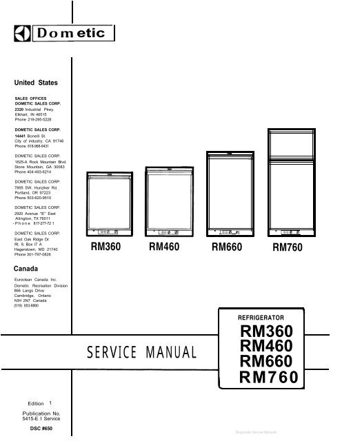
<strong>RM360</strong> <strong>RM460</strong><br />
SERVICE MANUAL<br />
” 1000 01<br />
<strong>RM660</strong> <strong>RM760</strong><br />
REFRIGERATOR<br />
, <strong>RM360</strong><br />
<strong>RM460</strong><br />
<strong>RM660</strong><br />
-1 <strong>RM760</strong>
Installation page 3<br />
Instructions for use page 6<br />
Cabinet adjustments<br />
To change door panel<br />
page 8<br />
page 8<br />
Panel dimensions page 8<br />
Replacement of door gasket page 9<br />
Reversing outer door page 9<br />
Replacement of evaporator door<br />
on <strong>RM360</strong>/460/660 page 9<br />
Replacement of evaporator door<br />
gasket on <strong>RM360</strong>/460/660 page 10<br />
The absorption cooling unit page 10<br />
Operation analysis for cooling unit page 10<br />
Cooling unit replacement <strong>RM360</strong>/460/660 page 11<br />
Cooling unit replacement <strong>RM760</strong> page 12<br />
The gas/electric equipment page 13<br />
Replacement of gas/electric<br />
equipment complete page 14<br />
Disassembly of gas/electric equipment page 14<br />
Disassembly of burner jet and burner page 15<br />
Operation analysis for LP gas refrigerators -page 15<br />
Operation analysis for refrigerators<br />
operating on electricity page 16<br />
Wiring diagrams page 17-18<br />
2
3<br />
INSTALLATION ELECTRICAL CONNECTION<br />
GENERAL INSTRUCTIONS 115 Volts A C<br />
The refrigerators outlined hereon have been design<br />
certified under ANS Z 21.19 Refrigerators<br />
by the American Gas Association for installation<br />
in a mobile home or recreational vehicle and are<br />
approved by the Canadian Gas Association. The<br />
certifications are, however, contingent on the<br />
installation being made in accordance with the<br />
following instructions.<br />
The installation must in the USA conform with:<br />
1. National Fuel Gas Code Z223.1-1974<br />
2. Mobile Homes A119.1-1972<br />
3. Recreational Vehicles A119.2-1970<br />
The unit must be electrically grounded in accordance<br />
with the National Electrical Code ANSI, CI-<br />
1968, when installed if an external alternating<br />
current electrical source is utilized.<br />
4. Any applicable local code<br />
In Canada<br />
1. Standard CGA lO.l/CSA 2240.4 gas equipped<br />
mobile housing and recreational vehicles<br />
2. Standard CSA Z240.6.1 electrical requirements<br />
for mobile housing<br />
The refrigerator is equipped with a three<br />
prong (grounded) plug for protection against<br />
shock hazard and should be plugged directly<br />
into a properly grounded three prong receptacle.<br />
Do not cut or remove the grounding<br />
prong from this plug. The cord should be<br />
routed to avoid coming in contact with the<br />
burner cover, flue cover or other hot components.<br />
12 Volts VDC optional for certain models<br />
On "Tri-Pover" units there is an additional<br />
terminal block marked "12 V". The refrigerator<br />
must be connected to the battery circuit<br />
with two wires of adequate capacity to avoid<br />
voltage drop. The wire gage should be chosen<br />
with consideration to the wire length in<br />
accordance with the following tabel: The 12 V<br />
circuit must be fused with an appropriate<br />
fuse.<br />
TABLE<br />
3. Standard CSA Z240.6.2/C22.2 No 148 electrical<br />
requirements for recreational vehicles AWG<br />
Ventilation<br />
The installation shall be made in such a manner<br />
as to separate the combustion system from the<br />
living space of the mobile home or recreational<br />
vehicle. Openings for air supply or for venting<br />
of combustion products shall have a minimum dimension<br />
of not less than l/4 inch.<br />
Proper installation requires one lower fresh air<br />
intake and one upper exhaust vent. The ventilation<br />
kits shown in this instruction booklet have<br />
been certified for use with the refrigerator models<br />
listed in the tables. The ventilation kits<br />
must be installed and used without modification.<br />
An opening towards the outside at floor level in<br />
the refrigerator compartment must be provided for<br />
ventilation of heavier-than-air fuel gases. The<br />
lower vent of the recommended kits is provided<br />
with proper size opening.<br />
For ready serviceability of the burner and control<br />
manifold parts of the refrigerator the lower<br />
side vent is fitted with a lift-out panel which<br />
provides an adequate access opening.<br />
GAS CONNECTION<br />
Hook-up to the gas supply line is accomplished<br />
at the manual gas valve, which is furnished<br />
with a 3/8" SAE (UNF 5/8"-18) male flare<br />
connection. All completed connections should<br />
be checked for leaks with soapy water.<br />
The gas supply system must incorporate a<br />
pressure regulator to maintain a supply pressure<br />
of not more than 11 inches water gage.<br />
Maximum two conductor wire length for different<br />
AWG numbers.<br />
Maximum two conductor wire length in feet<br />
14 10<br />
12 17<br />
10 27<br />
8 43<br />
6 69<br />
4 110<br />
Do not use the body or chassis of the<br />
vehicle as a substitute for either of the two<br />
conductors. No other electrical equipment<br />
or lighting should be connected to the refrigerator<br />
circuit. The refrigerator will draw<br />
from l0-21 Amps at 12 Volt depending on model.<br />
CAUTION<br />
<strong>RM360</strong><br />
120w<br />
<strong>RM460</strong> <strong>RM660</strong> <strong>RM760</strong><br />
135w 175w 250W<br />
9 7 5<br />
15 12 8<br />
25 19 13<br />
40 31 22<br />
64 49 34<br />
102 79 55<br />
Do not operate the refrigerator on 12 Volt when<br />
the vehicle is parked. You will run out of<br />
battery in a rather short time.<br />
Fig.1 m
If possible the installation of a 12 Volt<br />
operated refrigerator should be completed with<br />
a relay mounted either in the car or in the<br />
recreational vehicle (see Fig. 1). This relay<br />
will automatically cut out the refrigerator<br />
when the car motor is stopped.<br />
SPECIAL HINTS<br />
The refrigerator must be installed in a substantial<br />
enclosure and must be level. A spirit<br />
level is supplied with each refrigerator and<br />
by placing it in the freezer compartment one<br />
can level the refrigerator both ways front to<br />
back and side to side. When installing the refrigerator<br />
in the enclosure care should be<br />
taken to ensure a complete sealing between the /<br />
front frame of the refrigerator and the top,<br />
sides and bottom of the enclosure. For this<br />
purpose a length of sealing strip is applied<br />
to the rear surfaces of the front frame.<br />
A sealing strip should also be applied to the<br />
foremost floor of the enclosure as shown in<br />
Fig. 2.<br />
Be careful not to damage the sealing strip<br />
applied to the floor of the enclosure when the<br />
refrigerator must be blocked. The heat produced<br />
at the rear of the refrigerator will otherwise<br />
become trapped in this space making the top of<br />
the refrigerator hot and reducing the efficiency<br />
of the refrigerator.<br />
CERTIFIED INSTALLATION<br />
Certified installations require one roof vent<br />
and one lower side vent or as optional one<br />
upper vent and one lower side vent. The two<br />
alternatives are provided for by using the<br />
different kits listed in the Appendix.<br />
For further information contact your dealer<br />
or distributor.<br />
METHODS OF INSTALLATION<br />
The methods of installation are shown in<br />
figures 3 and 4. It is essential that all<br />
maximum or minimum dimensions are strictly<br />
maintained as the performance of the refrigerator<br />
is dependent on an adequate flow of<br />
air over the rear of the refrigerator.<br />
VENTILATION HEIGHTS<br />
:.jiiGj<br />
Refrige- Minimum ventilation heights in inches<br />
rator<br />
<strong>RM360</strong> 37 31<br />
<strong>RM460</strong> 34<br />
<strong>RM660</strong> 42<br />
<strong>RM760</strong> 56<br />
l-l _.<br />
Minimum w<br />
ventilation<br />
height<br />
Fig.3<br />
Ventilation<br />
area 5"x 18”<br />
4
5<br />
CLEARANCES<br />
Minimum clearances in inches to combustible<br />
materials are:<br />
G: Top 0<br />
K: Side 0<br />
L: Bottom 0<br />
M: Rear 1<br />
Clearance M between the rear-most part of the<br />
refrigerator and the wall behind the refrigerator.<br />
Clearance N on top of the condenser is related<br />
to the minimum ventilation height.<br />
See Fig. 5 and examples below.<br />
MEASUREMENTS<br />
Refrigerator Overall<br />
model dimensions<br />
Installation<br />
dimensions<br />
Recess<br />
dimensions<br />
Distance<br />
between top<br />
of condenser<br />
to top of<br />
Height<br />
A<br />
Width<br />
B<br />
Depth<br />
C<br />
Height<br />
h<br />
Width<br />
W<br />
Depth<br />
d<br />
Height Width<br />
H W<br />
Depth<br />
D<br />
refrigerator<br />
e<br />
Fig.5<br />
<strong>RM360</strong> 30 3/8 21 11/16 22 1/16 29 9/16 20 1/4 20 3/16 29 3/4 20 1/2 21 3/16 1 1/4<br />
<strong>RM460</strong> 32 15/16 23 24 11/16 32 1/8 21 9/16 22 3/4 32 5/16 21 13/16 23 3/4 1 1/4<br />
<strong>RM660</strong> 40 13/16 23 24 11/16 40 21 9/16 22 3/4 40 3/16 21 13/16 23 3/4 1 1/4<br />
<strong>RM760</strong> 52 23 24 11/16 51 3/16 21 9/16 22 3/4 51 3/8 21 13/16 23 3/4 1/8<br />
Storane volumes<br />
Refrigerator Total storage volume in cu ft<br />
model<br />
<strong>RM360</strong> 3.0<br />
<strong>RM460</strong> 3.9<br />
<strong>RM660</strong> 5.1<br />
<strong>RM760</strong> 6.0<br />
EXAMPLES<br />
The clearance N for the <strong>RM360</strong> model is derived<br />
atin<br />
the following way:<br />
A. Installation with upper and lower side vents.<br />
N=Minimum ventilation height 37 minus installation<br />
height 29 9/16 plus distance<br />
between condenser top and refrigerator top<br />
1 l/4<br />
N=37-29 9/16+1 l/4=8 11/16.<br />
B. Installation with roof vent and lower side<br />
vent.<br />
N=Minimum ventilation height 31 minus installation<br />
height 29 9/16 plus distance<br />
between condenser top and refrigerator top<br />
1 l/4 plus distance between roof surface<br />
and roof vent cap 5 l/4.<br />
N=31-29 9/16+1 l/4+5 l/4=7 15/16.<br />
Fig.6
INSTRUCTIONS FOR USE<br />
INSTALLATION OF THE REFRIGERATOR IN A VEHICLE<br />
The refrigerator must be installed on a solid<br />
floor and must be level. With the vehicle carefully<br />
leveled the refrigerator should level both<br />
ways in the freezer compartment.<br />
Free air circulation over the fins of the cooling<br />
unit is essential. Clearances around the refrigerator<br />
should be in accordance with the label<br />
attached to the rear plate of the refrigerator.<br />
In case detailed instructions on the installation<br />
and connection to the gas supply are required,<br />
contact your dealer or distributor.<br />
Leveling<br />
In the boiler ammonia vapor is distilled from an<br />
ammonia-water mixture and carried to the finned<br />
condenser, where it liquifies. The liquid flows<br />
to the evaporator, where it creates cold by<br />
evaporating into a circulating flow of hydrogen<br />
gas. If the evaporator coil is not level the<br />
liquid readily accumulates, forming pockets<br />
which can impair the gas circulation or even<br />
block it, in which case, of course, the cooling<br />
will stop.<br />
When the recreational vehicle is stationary it<br />
must be leveled to be comfortable to live in. If<br />
the refrigerator is properly installed, i e the<br />
freezer shelf parallel to the floor, the refrigerator<br />
will then also perform well.<br />
A bubble level should be placed on the freezer<br />
shelf. When the vehicle is on tow, the continuous<br />
rolling and pitching movement will not affect<br />
the refrigerator as long as the movement passes<br />
either side of level, but when the trailer is<br />
temporarily parked this sensitivity of the refrigerator<br />
should be remembered. So, once more,<br />
before you start the refrigerator, make sure<br />
it is level.<br />
HOW TO START THE REFRIGERATOR.<br />
Gas Operation(Fig. 7)<br />
1. To start<br />
position<br />
2. Turn the<br />
3. Push the<br />
D of the<br />
repeated<br />
This can<br />
Fig.7<br />
4. After the gas is lit keep the button C pushed<br />
for 10 seconds. Release the button and check<br />
through the reflector that the burner flame<br />
stays burning. If not repeat the lighting procedure.<br />
NOTE: After a replacement of the gas container<br />
or a long shut off period the gas<br />
line is likely to be filled with air. In<br />
such a case the lighting procedure has<br />
to be repeated until the air is pushed<br />
out of the line and the gas has reached<br />
the burner.<br />
Flame Blow Out<br />
If trouble is encountered with the flame blowing<br />
out under specially windy conditions, try to<br />
avoid the wind blowing against the wall where<br />
vent outlets are located. If the trouble persists,<br />
set the thermostat to MAX. This later measure<br />
can of course only be temporary such as when the<br />
vehicle is on tow, for after a day or so at this<br />
setting the foodstuffs in the cabinet will freeze.<br />
Electric Operation (Fig. 7)<br />
1.<br />
2.<br />
3.<br />
Check that the attachment plug is correctly<br />
connected to the mains supply. When the refrigerator<br />
is equipped also for 12 Volts D C<br />
operation the low voltage connection is made<br />
at the marked terminals at the rear of the refrigerator.<br />
Turn the knob A to desired position for electric<br />
operation.<br />
Turn the thermostat knob B to setting 4.<br />
HOW TO USE THE REFRIGERATOR<br />
Food Storage Compartment<br />
The food storage compartment is completely closed<br />
and unventilated, which is necessary to maintain<br />
the required low temperature for food storage.<br />
Consequently foods having a strong odor or liable<br />
to absorb odors should be covered. Vegetables,<br />
salads etc. should be covered to retain their<br />
crispness. The coldest positions in the refrigerators<br />
are underneath the cooling evaporator and<br />
at the bottom of the refrigerator, and the least<br />
cold positions are on the upper door shelves. This<br />
should be considered when different types of food<br />
are placed in the refrigerator.<br />
Frozen Food Storage Compartment<br />
The ice trays should be placed in direct contact<br />
with the freezer shelf for fastest ice making.<br />
Quick frozen soft fruits and ice cream should be<br />
placed in the coldest part of the compartment,<br />
the refrigerator turn the knob A to<br />
which is at the bottom of the aluminum liner or,<br />
in models with a shelf, on this or just below it.<br />
"GAS".<br />
Frozen vegetables, on the other hand, may be<br />
thermostat knob B to setting 4.<br />
button C to stop and push the button<br />
piezo igniter. The pushing has to be<br />
until the gas is lit at the burner.<br />
stored in any part of the compartment.<br />
The compartment is not designed for the deep or<br />
quick freezing of foodstuffs. Meat or fish foods,<br />
whether raw or prepared, and provided they are<br />
be observed through the reflector E. precooled in the refrigerator, can however, also<br />
6
7<br />
be stored in the frozen food storage compartment.<br />
They can then be stored about three times as<br />
long as in the fresh food storage compartment.<br />
To prevent drying out, keep food in covered<br />
dishes, in plastic bags or wrapped in aluminum<br />
foil.<br />
CAUTION<br />
Do not store explosive substances in the refrigerator,<br />
such as cigarette lighter gas,<br />
petrol, ether or the like.<br />
Ice Making<br />
Ice cubes can be made in the ice trays which<br />
should be filled with water to within l/4"<br />
(5 nun) from the top. To release the ice cubes<br />
seize the tray with both hands and twist the<br />
tray. Cubes not required should preferably<br />
be replaced in the tray. Refill the tray with<br />
water and replace the tray on the freezer<br />
shelf.<br />
Ice making is accelerated if the thermostat<br />
knob is turned to setting "MAX". It is a good<br />
idea to do this a few hours before an anticipated<br />
need for ice but be sure to turn the<br />
knob back to normal setting when the ice is<br />
formed or the foodstuffs in the cabinet may<br />
become frozen hard.<br />
Defrosting<br />
Some refrigerator models are equipped with an<br />
automatic defrosting device incorporated with<br />
the cooling unit. This device makes a quick<br />
defrost of the finned evaporator section about<br />
once a day without affecting the frozen food<br />
storage compartment or the frozen foods contained<br />
in. When the frozen food storage 'compartment is<br />
covered with frost the refrigerator must be shut<br />
down temporarily till the frost is melted. Before<br />
the refrigerator is restarted the compartment<br />
should be dried, the ice trays washed and refilled<br />
with fresh water.<br />
When the frost on the finned evaporator section<br />
has melted, water will be collected in the drip<br />
tray. The drip tray should be emptied at regular<br />
intervals.<br />
Some refrigerators without the automatic defrosting<br />
device should be defrosted regularly'<br />
by turning off the refrigerator. Empty the refrigerator<br />
leaving the drip tray under the finned<br />
evaporator and the cabinet and freezer doors<br />
open. If desired, defrosting may be speeded up<br />
by filling the ice tray with hot water and<br />
placing it in the freezer.<br />
When all frost is melted, empty the drip tray and<br />
dry the interior of the refrigerator with a<br />
clean cloth.<br />
Replace the drip tray and ice tray, replace all<br />
food stuffs and set the thermostat to "MAX" for<br />
a few hours. Then reset the thermostat knob to<br />
its normal position.<br />
To Shut Down the Refrigerator<br />
To shut down the refrigerator temporarily set<br />
the thermostat to off and turn off the gas tap.<br />
If the cabinet is not in operation over a period<br />
of weeks, it should be emptied and cleaned and<br />
the door left ajar. The ice trays should also<br />
be dried and kept outside the cabinet.<br />
Cleaning<br />
To clean the interior lining of the refrigerator<br />
use lukewarm weak soda solution. The evaporator,<br />
ice trays and shelves must, however, be cleaned<br />
with warm water only. Never use strong chemicals<br />
or abrasives to clean these parts or the protective<br />
surface will be spoiled. It is important<br />
always to keep the refrigerator clean.<br />
Periodic maintenance<br />
NOTE: Before working on the refrigerator, make<br />
sure that 110 V A. C. and optional 12 VD.C.<br />
leads are disconnected.<br />
Once or twice a year depending on use, it is<br />
necessary to clean and adjust the burner assembly.<br />
Proceed as follows:<br />
1.<br />
2.<br />
3.<br />
4.<br />
5.<br />
6.<br />
7.<br />
8.<br />
9.<br />
Loosen screw and remove cover plate for burner<br />
housing.<br />
Disconnect lighter cable from the electrode.<br />
Loosen burner fixing screw and withdraw burner.<br />
Clean burner tube with a brush. Blow with<br />
compressed air.<br />
Screw off jet and clean with alcohol. Blow<br />
with compressed air. Never use a needle or<br />
similar.<br />
Clean flue baffle and flue.<br />
Clean the cooling unit and the floor under the<br />
refrigerator.<br />
Reassemble.<br />
The entire gas installation should be checked<br />
for leaks. Test all pipe connections with<br />
soapy water, not with an open flame.
CABINET ADJUSTMENTS<br />
To change door panel<br />
The refrigerator is normally delivered without door<br />
panel(s). Before starting the mounting work check<br />
that the panel dimensions are in compliance with<br />
those given in the table and read the instructions<br />
through. When mounting the panel, proceed as follows:<br />
1.<br />
2.<br />
3.<br />
4.<br />
5.<br />
6.<br />
Remove the top decoration strip (2) with<br />
two screws (1).<br />
its<br />
Insert one of the vertical edges of the panel<br />
into the groove of the door frame (3).<br />
Bend the panel gently so that the free side of<br />
the panel can be slipped into the corresponding<br />
groove of the door frame (4).<br />
Push the panel downwards so that the lower horizontal<br />
edge of the panel is fitted into the<br />
bottom groove (5).<br />
Between the upper edge of the panel and the door<br />
frame there is now a gap which should be covered<br />
by the decoration strip.<br />
Put the strip across the door so that the gap<br />
is covered and push it upwards (6).<br />
The tabs on the inside of the strip should fit<br />
in behind the flange of the door frame. Secure<br />
the decoration strip by means of the two screws (1).<br />
Panel dimensions<br />
Thickness max. 5/32"<br />
Height Width<br />
Type Max. Min. Max. Min.<br />
RM 360 636 633 516,5 513,5 mm<br />
25" 24 7/8" 20 11/32" 20 7/32"inch<br />
RM 460 679 676<br />
550,5 547,5<br />
26 23/32" 26 19/32" 21 11/16" 21 9,16":ch<br />
RM 660 879 876 550,5 547,5 mm<br />
34 5/8" 34 l/2" 21 11/16" 21 9/16"inch<br />
RM 760 288 285 550,5 547,5 mm<br />
upper 11 11/32" 11 7/32" 21 11/16" 21 9/16"inch<br />
RM 760 801 798 550,5 547,5 mm<br />
lower 31 17/32" 31 13/32" 21 11/16" 21 9/16"inch<br />
Fig.8<br />
a
9<br />
Replacement of door gasket (Fig. 9)<br />
1. Pull the old gasket out from the door frame.<br />
2. Make sure that no gasket parts are left in<br />
the groove.<br />
3. Beginning in one of the corners, fit the new<br />
gasket by pressing it into the groove.<br />
Reversing outer door (Fig. 10)<br />
1. Remove the plastic cover (1) by loosening the<br />
screws (2) underneath.<br />
2. Remove the upper hinge pin (3).<br />
3. Remove the door and move the lower hinge pin (4)<br />
to the other side.<br />
4. Fit the door and press the upper hinge pin<br />
(3) into the adequate hole.<br />
For two-door refrigerators the middle hinge and<br />
the travel latch should change position.<br />
Replacement of evaporator door on <strong>RM360</strong>,<br />
<strong>RM460</strong>, <strong>RM660</strong> (Fig. 11 and 12)<br />
1.<br />
2.<br />
3.<br />
4.<br />
5.<br />
Pry the spring housings (B) away from the lining<br />
so that it snaps out and turn the spring<br />
housing downwards 180'.<br />
Push the carrier (A) inwards by means of a<br />
blunt mandrel or pin and remove the shutter.<br />
Mount the new shutter in close position first<br />
on one side, making sure that the cross slots<br />
engage in the cross on the hinge plate (C).<br />
Press the carrier on the opposite side so that<br />
the hinge plate on the shutter can be pushed<br />
over it. See that the crosses engage.<br />
Turn the spring housing round and up until the<br />
small tag (D) snaps into the slot into the<br />
lining.<br />
Fig.9<br />
Fig.10<br />
Fig.11 Fig.12
Replacement of evaporator door gasket on <strong>RM360</strong>,<br />
<strong>RM460</strong>, <strong>RM660</strong><br />
1. Remove the door as previously described.<br />
2. Unscrew the hinge plates (A fig. 13).<br />
3. Put shutter on a flat surface with the sealing<br />
gasket up.<br />
4. Pry the shutter front away from the inner<br />
pan by means of a screwdriver.<br />
CAUTION: It is of great importance that the<br />
screw driwer is applied in front of one of<br />
the plastic tongues (B fig. 13) which hold<br />
the inner panel and the shutter front together.<br />
5. Replace the sealing gasket round the inner<br />
panel and snap the inner panel with<br />
sealing gasket into the shutter front<br />
until the tongues snap in position.<br />
6. Mount the shutter as described above.<br />
THE ABSORPTION COOLING UNIT<br />
Sealed system construction<br />
Fig.13<br />
The sealed system of the absorption refrigerator If an excessive vaporizing of the ammonia within the<br />
is constructed of welded steel piping which con- boiler occurs due to the reasons above, the liquid<br />
tains the refrigerant charge. The charge consists mixture in the boiler becomes very weak and the pump<br />
of ammonia, hydrogen and water. There are no mo- will cease to operate, which means that the circulaving<br />
parts associated with the absorption system. tion of liquid stops with the result that the evaporator<br />
inside the cabinet ceases to produce cooling.<br />
When servicing an absorption system refrigerator, Such a blockage of the unit in the liquid circuit<br />
do not puncture or break the piping. Should a ist most usually made evident by signs of overheabreak<br />
occur and ammonia contact the skin, wash the ting on the vapour pipe leading from the boiler to<br />
affected area immediately with clear water. Do not the condenser, the paint on this pipe being blisteattempt<br />
to open the valve on the absorber vessel. red and the metal becoming discouloured.<br />
The valve is covered with a plastic can and should<br />
never be removed. To remedy this fault it is recommended to remove the<br />
OPERATION ANALYSIS FOR COOLING UNIT<br />
It is obviously important that all external factors<br />
affecting the unit should be checked properly<br />
before a unit is condemned as faulty and that emphasis<br />
has been placed upon the necessity for correct<br />
installation, upright refrigerator, correct heat input,<br />
baffle position, etc. Check the size and the<br />
wattage of the electric heater and make sure that<br />
the heater element is inserted to its full length<br />
in its pocket. If the electric heater is only partly<br />
inserted, the heat distribution will be incorrect,<br />
causing an excessive vaporizing of the ammonia within<br />
the boiler when operating on electricity. The same<br />
symptom can show up with too much or too little<br />
unit or refrigerator complete whenever possible and<br />
to allow sufficient time to- cool down the unit. Turn<br />
the unit or refrigerator upside down several times,<br />
so that the liquid in the absorber vessel can be<br />
mixed with the liquid in the boiler. This procedure<br />
will restore the liquid balance to the unit.<br />
The temperatures on various parts of a unit vary<br />
continuously when it is operating on thermostatic<br />
control and it is impossible to base a judgment on<br />
the symptoms given unless the refrigerator has been<br />
operating continuously on fully correct heat input<br />
for at least 5 hours, and preferably 12 hours, prior<br />
to examination. In many cases this can be arranged<br />
by a telephone call to the customer, asking him to<br />
switch the thermostat to "MAX" on the day before the<br />
heat input either on electric or on gas operation inspection call. If after 12 hours' operation on<br />
and also if the refrigerator had been operating in "MAX" the performance is satisfactory, the unit is<br />
an off-level position or with inadequate ventila- not at fault unless the complaint is one of varying<br />
tion. or intermittent performance. In this connection
11<br />
the room temperature at the time of the complaint<br />
must be considered, as a unit which is satisfactory<br />
Unit filling valve<br />
at an ambient temperature ofo650F (+18OC) may not The needle valve used for admitting the filling<br />
be satisfactory at 95 F (+35 C).<br />
charge to a cooling unit is fitted to the unit's<br />
absorber vessel and is covered by an aluminium or<br />
In cases where satisfactory performance is obtained plastic cap. It is strictly applied provision of<br />
"MAX" but not on other settings, the thermostat the warranty extended on the unit to the customer,<br />
is to be suspected.<br />
that any interference with the filling valve will<br />
automatically void the warranty.<br />
When a normal unit is working on "MAX" the absorber<br />
coil will be warmer at the bottom than it is at the Unsatisfactory unit performance due to an ammonia<br />
top. The absorber vessel will be warmer. The vapour leak can be determined in the case of a visible<br />
cooling pipe from the boiler to the condenser will leak by traces of a yellow deposit at the point<br />
be warm, bearably to the hand, at the bend where where the ammonia is escaping. If there is a leak<br />
it joins the condenser, with a gradual rise in tem- on the evaporator inside the cabinet, a smell of<br />
perature towards the boiler end. ammonia may bee noticeable.<br />
COOLING UNIT REPLACEMENT <strong>RM360</strong>, <strong>RM460</strong>, <strong>RM660</strong><br />
Remove the refrigerator from its recess as follows<br />
1. Check that refrigerator is empty and remove<br />
ice tray.<br />
2. Turn off gas bottle.<br />
3. Disconnect gas line to inlet valve<br />
CAUTION: Use a backup wrench to prevent<br />
undue rotation.<br />
4. Unplug the electric line from the trailer<br />
outlet.<br />
5. Remove the 4 screws in rear front frame.<br />
6. Check for any additional screws which the<br />
vehicle manufacturer may have used to<br />
fasten the refrigerator in place.<br />
7. Carefully slide the refrigerator straight<br />
out of its recess.<br />
To remove the cooling unit from the cabinet,<br />
proceed as follows:<br />
1. Place the refrigerator on a work bench of<br />
suitable height.<br />
2. Remove the thermostat capillary tube by<br />
loosening the two screws (1) on the evaporator<br />
fins (fig. 14).<br />
CAUTION: The locations of the thermostat<br />
capillary tube should be noted at this<br />
time for relocation later on. The tubes<br />
must be placed in the right position,<br />
otherwise, improper performance may result.<br />
3. Remove the two sealing plugs for capillary<br />
tube, one on the back and one inside the<br />
cabinet, and straighten the tubes.<br />
4. Remove the capillary tubes by going to the<br />
back of the refrigerator and gently pulling<br />
the tubes straight out.<br />
Fig.14<br />
Fig.15<br />
-6
5.<br />
6.<br />
7.<br />
8.<br />
9.<br />
10.<br />
11.<br />
12.<br />
CAUTION:<br />
Remove the screws (2) in fig. 14 and take away the<br />
evaporator fin. Remove the screws (3).<br />
Remove the connection block (4) cover (Fig. 15) and disconnect<br />
the electrical wires for the heaters.<br />
Remove the grounding screw (5).(Fig. 15).<br />
Remove the flue and the flue baffle.<br />
Remove the screws (6), holding the absorption unit<br />
onto the back of the cabinet.<br />
Disconnect the burner case by turning the lever<br />
(7) as shown in the picture.<br />
Carefully bend absorption unit out of cabinet<br />
(Use a crowbar or similar and a wooden piece as<br />
protection when doing this).<br />
To replace absorption unit, reverse above procedure.<br />
1. Be sure to apply sealing permagum (8) on the<br />
unit mounting plate (Fig. 16).<br />
2. Be sure to apply proper amount of "Thermal Mastic"<br />
on the evaporator coil (9).<br />
3. When fitting the evaporator fin be sure to tighten<br />
the screws properly in order to obtain a perfect<br />
contact between the evaporator coil and evaporator<br />
flange, otherwise improper cabinet performance<br />
may result.<br />
COOLING UNIT REPLACEMENT <strong>RM760</strong><br />
The following steps are different from the models <strong>RM360</strong>,<br />
<strong>RM460</strong> and <strong>RM660</strong>.<br />
1. The screws (1) in the freezer should be removed (Fig. 18)<br />
2. The capillary tube should carefully be pulled<br />
out from the tube (2).(Fig. 19).<br />
3. When bending the cooling unit out, place the crowbar<br />
or similar as well as the wooden protection as shown<br />
in the picture.<br />
8 9<br />
Fig.16 Fig.17<br />
Fig.18<br />
Fig.19<br />
12
13<br />
THE GAS/ELECTRIC EQUIPMENT<br />
Gas equipment parts<br />
1. Burner tube<br />
2. Burner, housing<br />
3. Jet<br />
4. Feeler point thermocouple)<br />
5. Flame failure safety device<br />
6. Bypass screw<br />
7. Gas/Electric thermostat<br />
8. Pressure test gage connection<br />
9. Capillary tube for thermostat<br />
10. Shut-off value<br />
11. Piezo igniter<br />
12. Firing tip<br />
13. Flue baffle<br />
Fig.20<br />
Electric equipment parts<br />
14. Flexible cord<br />
15. Change-over switch<br />
16. Terminal block, 12 VDC<br />
17. Fuse<br />
18. Relay<br />
19. Heater
Replacement of gas/electric equipment complete<br />
1. Remove the covers by removing the screws (1).<br />
2. Disconnect the heater cords at the terminal<br />
blocks (note the locations for later relocation).<br />
3. Remove the capillary tube carefully from the<br />
evaporator.<br />
4. Remove the screws (2).<br />
5. Release the burner housing from the flue by<br />
turning the lever (3) as shown.<br />
6. Pull the equipment out from the cabinet.<br />
Disassembly of gas electric/equipment<br />
1.<br />
2.<br />
3.<br />
4.<br />
5.<br />
6.<br />
7.<br />
Press the plastic latch (leftwards<br />
in Fig. 22).<br />
Pull the relay out (if any).<br />
Snap off the fuse holder.<br />
Press the spring.<br />
Pull the shut-off valve out.<br />
Press the gas/electric thermostat leftwards<br />
and lift it out.<br />
Unscrew the thermocouple from the flame<br />
failure safety device.<br />
0 2<br />
Fig.22<br />
Fig.21<br />
14<br />
1 1 115v<br />
. 220v<br />
240v<br />
_12V<br />
ZI<br />
8. Press the retaining spring for release of<br />
thermocouple.<br />
9. Pull out the thermocouple leftwards.<br />
10. Pull the flame failure safety device left<br />
and lift it out.<br />
11. Pull off the ignition cord.<br />
12. Snap off the retaining spring.<br />
13. Pull out the igniter.<br />
NOTE: When assembling, always use new O-rings<br />
-<br />
for the joints.
15<br />
DISASSEMBLY OF BURNER JET AND BURNER<br />
1. Remove the cover by removing the screw (1).<br />
2. Unscrew the burner jet (2).<br />
3. Remove the burner by removing the screw (3)<br />
OPERATION ANALYSIS FOR LP GAS REFRIGERATORS<br />
SYMPTOM CAUSE<br />
P<br />
z<br />
:<br />
T1z<br />
48 u<br />
8 8<br />
Note: It will be noted in this tabulation that<br />
2:: 2 c .rl<br />
c .z : ‘;:<br />
8 ;:<br />
S<br />
c)<br />
8” ”<br />
c .;<br />
l.l<br />
MZ<br />
several causes can be responsible for the one<br />
effect. The real cause or causes should be de-<br />
termined by a process of elimination, investi-<br />
5 ‘d 2<br />
g j $ .j<br />
z : L<br />
*<br />
0) 2 .rl&W .rl<br />
z<br />
g<br />
MW 4.l<br />
‘;: ‘C<br />
z u ti<br />
:<br />
;: :<br />
?”<br />
: z<br />
diz$LZ80a<br />
gation each possible cause. proceeding to the<br />
bottom.<br />
x Gas leaks<br />
Fig.24
OPERATION ANALYSIS FOR REFRIGERATORS OPERATING ON ELECTRICITY<br />
r SYMPTOM<br />
CAUSE<br />
- - -<br />
2 0<br />
”<br />
0”<br />
u<br />
z<br />
zl<br />
L!<br />
E<br />
.?I<br />
u<br />
v-4<br />
d<br />
-<br />
-<br />
-<br />
X<br />
-<br />
-<br />
-<br />
X<br />
-<br />
- X<br />
-<br />
272<br />
2<br />
5<br />
a rl<br />
0 0<br />
4-l<br />
“d<br />
g<br />
z<br />
5cc<br />
‘;1<br />
ICI<br />
d-<br />
x<br />
-<br />
X<br />
-<br />
X<br />
-<br />
X<br />
-<br />
-<br />
X<br />
-<br />
X<br />
-<br />
X<br />
-<br />
-<br />
X<br />
-<br />
-<br />
-<br />
-<br />
-<br />
X<br />
-<br />
X<br />
-<br />
-<br />
ii!<br />
.d<br />
2 u<br />
s<br />
.rl<br />
G it<br />
2- X<br />
- X<br />
- X<br />
- X<br />
- X<br />
- X<br />
- X<br />
- X<br />
-<br />
- X<br />
-<br />
-<br />
-<br />
-<br />
- X- X<br />
-<br />
-<br />
5<br />
G<br />
*rl<br />
ls<br />
w<br />
%<br />
2 &J<br />
8<br />
iz-<br />
-<br />
-<br />
-<br />
-<br />
-<br />
- X<br />
-<br />
X<br />
-<br />
-<br />
X<br />
-<br />
-<br />
-<br />
-<br />
4-l<br />
2 .rl<br />
-G<br />
”<br />
4<br />
.d<br />
“d .d<br />
t.4<br />
0’<br />
0”<br />
-<br />
-<br />
-<br />
-<br />
-<br />
-<br />
-<br />
-<br />
-<br />
-<br />
- X<br />
- X<br />
- X<br />
-<br />
-<br />
-<br />
-<br />
-<br />
Note: It will be noted in this tabulation that<br />
several causes can be responsible for the one<br />
effect. The real cause or causes should be deter-<br />
mined by a process of elimination, investigating<br />
each possible cause, starting at the top of the<br />
tabulation and proceeding to the bottom.<br />
Not adequate ventilation<br />
Refrigerating unit not level<br />
Heater faulty,wrong voltage or type<br />
Voltage not constant<br />
Electric connections loose<br />
Heater not inserted correctly in its pocket<br />
Improper food storage<br />
The thermostat incorrectly used<br />
Improper storage of liquids and moist foods<br />
Leaky cabinet seals<br />
Infrequent cleaning of food compartment<br />
Refrigerator shut off with closed door<br />
Unwrapped odorous food<br />
<strong>Inc</strong>omplete contact of thermostat capillary tube<br />
Lost thermostat charge<br />
Failed refrigerating unit<br />
Room temperature too low<br />
16
17<br />
200 7390<br />
N<br />
L<br />
12VOLTS DC<br />
@ GREEN<br />
@ GREEN/YELLOW<br />
12VOLTS DC<br />
115 VOLTS AC<br />
Fig.25 Wiring Diagram for Product No. 926 63 01<br />
<strong>RM760</strong><br />
115VOLTS AC<br />
Fig.26 Wiring Diagram for Product No. 926 63 02<br />
<strong>RM760</strong><br />
THERMOS TAT<br />
0 JUNCTION BLOCK<br />
0 TERMINAL BLOCK
20075871<br />
115VOLTS AC<br />
@ SWITCH<br />
@I THERMOS TAT<br />
8 JHEyTIRm BLOCK<br />
@ WHITE<br />
@ BLACK<br />
@ GREEN<br />
Fig.27 Wiring Diagram forProduct No. 926 69 01, 926 70 01, 926 71 01<br />
<strong>RM360</strong> <strong>RM460</strong> <strong>RM660</strong><br />
6 BLACK<br />
@j GREEN<br />
@ GREEN/YEL LOW<br />
-I<br />
115 VOLTS AC<br />
m<br />
---<br />
N_<br />
l<br />
Lr-7<br />
I<br />
8, I<br />
zzz<br />
Fig.28 Wiring Diagram for Product NO. 92 6 02, 92 7 02, 926 71 02<br />
<strong>RM360</strong> <strong>RM460</strong> <strong>RM660</strong><br />
@ SWITCH<br />
@I THERMOSTAT<br />
0 JUNCTION BLOCK<br />
@ HEATER<br />
e> TERMINAL BLOCK<br />
8 FUSE<br />
@ HEATER<br />
18