bargraph digital indicators na2 series user's manual - Wpa.ie
bargraph digital indicators na2 series user's manual - Wpa.ie
bargraph digital indicators na2 series user's manual - Wpa.ie

You also want an ePaper? Increase the reach of your titles
YUMPU automatically turns print PDFs into web optimized ePapers that Google loves.
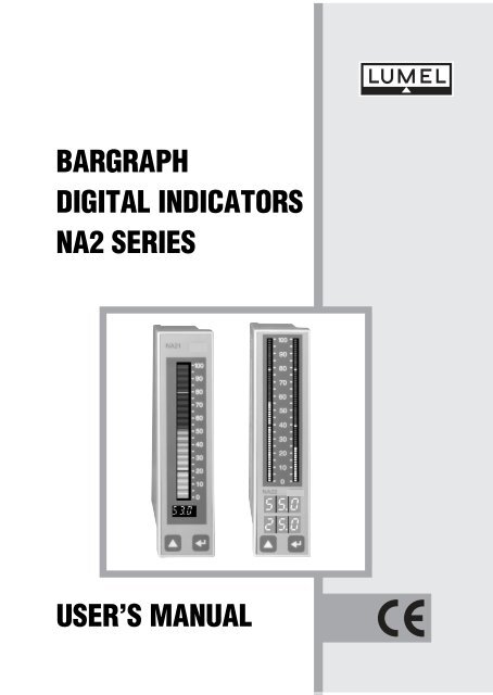
BARGRAPH<br />
DIGITAL INDICATORS<br />
NA2 SERIES<br />
USER’S MANUAL
BARGRAPH<br />
DIGITAL INDICATORS<br />
NA2 SERIES<br />
CONTENTS<br />
Page<br />
1. APPLICATION ....................................................................... 3<br />
2. BASIC REQUIREMENTS, OPERATIONAL SAFETY ........... 4<br />
3. FITTING ................................................................................. 5<br />
4. CONNECTION ....................................................................... 6<br />
5. SERVICING ........................................................................... 9<br />
6. PROGRAMMING ................................................................. 12<br />
7. TECHNICAL DATA .............................................................. 21<br />
8. ORDERING PROCEDURE ................................................. 26<br />
9. MAINTENANCE AND WARRANTY .................................... 27<br />
3
1. APPLICATION<br />
NA2 <strong>ser<strong>ie</strong>s</strong> <strong>bargraph</strong> panel meters with <strong>digital</strong> and analog indications<br />
are destined to measure d.c. voltages and d.c. currents, temperature,<br />
resistance and other non-electrical quantit<strong>ie</strong>s converted<br />
into electrical signals.<br />
They can realize additional functions such as:<br />
· overrun signalling of setting alarm values,<br />
· overrun signalling of the measuring range,<br />
· programmable resolution of the <strong>bargraph</strong>,<br />
· recalculation of the measured quantity into any arbitrary<br />
quantity on the base of an individual lineal characteristic<br />
y = ax + b,<br />
· conversion of the measured quantity into a current or voltage<br />
standard signal,<br />
· <strong>digital</strong> communication through the RS-485 interface, with the<br />
MODBUS protocol,<br />
· supply of two-wire object transducers (24 V) in the following<br />
measuring range executions: 0/4...20 mA, 0...1 V, 0...10 V.<br />
With the meter we deliver:<br />
· a warranty card,<br />
· 2 holders to fix the meter into a panel,<br />
· a service <strong>manual</strong>,<br />
· a service <strong>manual</strong> for execution with an interface,<br />
· a set of stickers with units.<br />
When unpacking the meter, please check whether the type and<br />
execution code on the data plate corresponds to the order.<br />
5
Symbols located in this service <strong>manual</strong> meant:<br />
- Especially important, one must acquaint with this before con-<br />
!<br />
necting the meter.<br />
- One must take note of this when the meter is working incon-<br />
? sistently to the expectations.<br />
2. BASIC REQUIREMENTS, OPERATIONAL SAFETY<br />
NA2 meters are destined to be mounted into panels and cubicles. In<br />
the range of operational safety, they are in conformity with the IEC<br />
1010 standard requirements.<br />
Remarks concerning the safety: !<br />
· The installation and meter connection should be operated by<br />
qualif<strong>ie</strong>d personel. One must take into consideration all<br />
accessible protection requirements.<br />
· Before switching the meter on, one must check the correctness<br />
of the network lead connection.<br />
· One must take care especially of the protection terminal<br />
connection IEC1010-1 p. 6.10 and p. 6.11.2 standard.<br />
· In the case of the protection terminal connection with a separate<br />
lead one must remember to connect it before the connection of<br />
network leads.<br />
· Do not connect the meter to the network through an<br />
auto-transformer.<br />
· Before taking the meter housing out one must turn the supply<br />
off.<br />
· The removal of the meter housing during the warranty period<br />
causes its cancellation.<br />
6
3. FITTING<br />
Prepare a (34 +0.6 x 137 +1 !<br />
) mm hole in the panel. The thickness of<br />
the material from which the panel is made can not exceed 20 mm.<br />
One should introduce the meter from the front of the panel with disconnected<br />
supply circuit.<br />
After introducing the meter, fasten it by means of holders.<br />
NA21<br />
18<br />
36<br />
100<br />
90<br />
80<br />
70<br />
60<br />
50<br />
40<br />
30<br />
20<br />
10<br />
0<br />
144<br />
130<br />
118<br />
36<br />
100<br />
0<br />
NA22<br />
Fig. 1. Meter overall dimensions<br />
90<br />
80<br />
70<br />
60<br />
50<br />
40<br />
30<br />
20<br />
10<br />
144<br />
33<br />
7
4. CONNECTION<br />
At the rear side of the meter there are terminal strips with screw<br />
terminals. Analog and <strong>digital</strong> outputs of the meter are galvanically<br />
isolated from other parts of the system.<br />
(1) - exists only in executions with two relays,<br />
(2) - exists only in executions with a 0/4...20 mA or 0...10 V analog output,<br />
(3) - exists only in executions with RS-485 interface,<br />
(4) - exists only in executions with a 0/4...20 mA, 0...1 V, 0...10 V measuring range.<br />
Fig. 2. Description of NA21 meter terminals<br />
8<br />
ALARM 2<br />
channel 1 1)<br />
ALARM 1<br />
channel 1<br />
2)<br />
RS-485 3)<br />
+<br />
A<br />
B<br />
GND<br />
E<br />
30<br />
29<br />
28<br />
27<br />
26<br />
25<br />
24<br />
23<br />
22<br />
21<br />
20<br />
19<br />
18<br />
17<br />
15<br />
14<br />
13<br />
12<br />
11<br />
10<br />
9<br />
8<br />
7<br />
6<br />
5<br />
4<br />
3<br />
2<br />
16 1<br />
+<br />
+<br />
N<br />
L<br />
RTD<br />
230 V a.c., d.c. or 24 V a.c., d.c.<br />
(according to execution)<br />
24V d.c. 4)<br />
CHANNEL 1
RS-485 3)<br />
ALARM 4<br />
channel 2 1)<br />
ALARM 3<br />
channel 1 1)<br />
2)<br />
ALARM 2<br />
channel 2<br />
ALARM 1<br />
channel 1<br />
+<br />
A<br />
B<br />
GND<br />
E<br />
30<br />
29<br />
28<br />
27<br />
26<br />
25<br />
24<br />
23<br />
22<br />
21<br />
20<br />
19<br />
18<br />
17<br />
15<br />
14<br />
13<br />
12<br />
11<br />
10<br />
9<br />
8<br />
7<br />
6<br />
5<br />
4<br />
3<br />
2<br />
16 1<br />
230 V a.c., d.c. or 24 V a.c., d.c.<br />
(according to execution)<br />
24V d.c. 4)<br />
(1) - exists only in executions with four relays,<br />
(2) - exists only in executions with a 0/4...20 mA or 0...10 V analog output.<br />
(3) - exists only in executions with RS-485 interface,<br />
(4) - exists only in executions with a 0/4...20 mA, 0...1 V, 0...10V measuring range,<br />
Fig. 3. Description of NA22 meter terminals<br />
+ + +<br />
N<br />
L<br />
RTD<br />
RTD<br />
CHANNEL 2<br />
CHANNEL 1<br />
9
a)<br />
Channel 2<br />
Channel 1<br />
Channel 2<br />
Channel 1<br />
Fig. 4. Connection way of the input<br />
signal:<br />
a/ temperature sensors and the potentiometric<br />
transmitter,<br />
b/ voltage,<br />
c/ current<br />
d/ object transducers.<br />
!<br />
- In case of meters working in an environment of high perturbances<br />
one should use external filters.<br />
- It is recommended to use screened leads on the output and input<br />
of the meter.<br />
10<br />
4 5 6 4 5 6<br />
1 2 3 1 2 3<br />
Thermocouple<br />
or -5...60 mV<br />
Resistance<br />
thermometer<br />
probe in a<br />
two-wire system<br />
4 5 6<br />
1 2 3<br />
b) c) d)<br />
4 5<br />
1 2<br />
- +<br />
U =<br />
4 5 6<br />
1 2 3<br />
- +<br />
Resistance<br />
thermometer<br />
probe in a<br />
three-wire system<br />
4 6<br />
1 3<br />
-<br />
+<br />
I<br />
4 6<br />
1 3<br />
-<br />
+<br />
S<br />
I<br />
4 5 6<br />
1 2 3<br />
Potentiometer<br />
transmitter<br />
7<br />
8<br />
7 8<br />
2-wire<br />
transducer<br />
7<br />
8<br />
7 8<br />
3-wire<br />
transducer
- One must use a three-wire cable as a network supplying cable.<br />
The lead section should be chosen in such a way that in case of a<br />
cable short-circuit from the equipment side, the cable would be<br />
protected by means of electrical installation fuses. Requirements<br />
towards the network cable are regulated by the IEC 1010-1 p.6.10.<br />
standard.<br />
5. SERVICING<br />
After switching the meter on, its name is displayed and also alarms<br />
currently set are displayed on the <strong>bargraph</strong>. The meter is transiting<br />
automatically into the measuring mode and the input signal value is<br />
displayed.<br />
Alarm thresholds are marked as lighted or extincted segments<br />
NA21<br />
100<br />
90<br />
80<br />
70<br />
60<br />
50<br />
40<br />
30<br />
20<br />
10<br />
0<br />
upper alarm threshold<br />
100 - segment <strong>bargraph</strong><br />
lower alarm threshold<br />
3x5mmdigits<br />
keys<br />
11
Key functions:<br />
· entry into the programming mode (hold down during ca 3<br />
seconds),<br />
· entry and moving through the parameter group of the chosen<br />
level,<br />
· return into the measuring mode,<br />
· acceptation of the changed parameter value.<br />
· displaying resolution increase of the measured quantity (in the<br />
measuring mode),<br />
· choice of the parameter group level,<br />
· change of the chosen parameter value,<br />
· exit from the parameter group of the chosen level.<br />
12<br />
100<br />
90<br />
80<br />
70<br />
60<br />
50<br />
40<br />
30<br />
20<br />
10<br />
0<br />
NA22<br />
alarm threshold<br />
64 - element <strong>bargraph</strong><br />
(channel 1)<br />
64 - element <strong>bargraph</strong><br />
(channel 2)<br />
3 x 7.5 mm digits<br />
(channel 1)<br />
3 x 7.5 mm digits<br />
(channel 2)<br />
keys
In case of the switched off individual characteristic, the meter establishes<br />
automatically the position of the decimal point.<br />
A pressure of the key produces the increase of the quantity display<br />
resolution. In this mode, the oldest digit is not displayed.<br />
The release of the key causes the return to the normal display.<br />
A simultaneous pressure of keys and and their hold down<br />
during ca 10 seconds causes the display of the actual security code.<br />
The operation algorythm of the meter is shown on fig. 5.<br />
Increase of the<br />
measured quantity<br />
display resolution<br />
Display of the<br />
actual security<br />
code<br />
10 seconds<br />
Switching on<br />
to the network<br />
Display of NA2<br />
name and actual<br />
alarm thresholds<br />
MEASUREMENT<br />
Display of the<br />
"Err" incription<br />
3 seconds<br />
Uncorrect<br />
entry<br />
Introducing mode<br />
of "SEC" entry<br />
0... 999<br />
Checking<br />
of the introduced<br />
entry<br />
Fig. 5. Operation algorythm of the meter.<br />
Correct<br />
entry<br />
Programming<br />
mode<br />
13
The appearance of the following symbols on the <strong>digital</strong><br />
displays means:<br />
14<br />
- Uncorrect introducing of the security code.<br />
- Exceeding of the upper measuring range or a lack of<br />
sensor, <strong>bargraph</strong> lighted up.<br />
- Exceeding of the lower measuring range or sensor<br />
short-circuited, <strong>bargraph</strong> extincted.<br />
6. PROGRAMMING<br />
The key pressure and its holding down during ca 3 seconds causes<br />
the display of the security code symbol SEC alternatively with<br />
the 0 value set by the manufacturer. The entrance of the correct<br />
code causes the transition into the programming mode.<br />
The transition matrix into the programming mode is shown on the fig. 6.<br />
We choice the level selection by means of the key , whereas the<br />
input and moving through parameters of the chosen level is carr<strong>ie</strong>d<br />
out by means of the key . Parameter symbols are displayed alternatively<br />
with their actual values. In order to change the values one<br />
should use the key .<br />
Changing way of chosen parameter values.<br />
Each digit is changed separately by means of the key and is<br />
accepted by the key .<br />
In case of the Y1 parameter, after accepting the last digit, one<br />
should set the decimal point by means of the key and accept it by<br />
the key.<br />
?
In the programming mode, the actual level number is displayed on<br />
the <strong>bargraph</strong> by the luminescence of successive decades.<br />
Lev Ch1 tYP Con LiP BrL Brh Ind H1 Y1 H2 Y2<br />
No<br />
1<br />
Channel<br />
1<br />
Sensor Kind of<br />
type comp.<br />
(1) (1)<br />
Number<br />
of<br />
measur.<br />
Lower<br />
<strong>bargraph</strong><br />
Upper<br />
<strong>bargraph</strong><br />
Linear<br />
character.<br />
(2) (2) (2)<br />
---<br />
(2) (w)<br />
Ch2 tYP Con LiP BrL Brh Ind H1 Y1 H2 Y2<br />
2 Channel<br />
2<br />
(3)<br />
Sensor Kind of Number<br />
type comp. of<br />
measur.<br />
(1) (1)<br />
Lower<br />
<strong>bargraph</strong><br />
Upper<br />
<strong>bargraph</strong><br />
Linear<br />
character.<br />
(2) (2) (2) (2)<br />
---<br />
(w)<br />
3<br />
AL1<br />
Alarm 1<br />
PrL Prh<br />
Lower Upper<br />
threshold threshold<br />
tYP<br />
Alarm<br />
type<br />
---<br />
(w)<br />
(w) -<br />
(0) -<br />
exit from the parameter group of chosen<br />
level,<br />
exit from the programming mode,<br />
4<br />
AL2 PrL Prh<br />
Alarm 2 Lower Upper<br />
(6) threshold threshold<br />
tYP<br />
Alarm<br />
type<br />
---<br />
(w)<br />
(1) -<br />
(2) -<br />
occurs only in meters for temperature<br />
measurement,<br />
occurs only, when the individual<br />
characteristic is included (Ind = On),<br />
5<br />
6<br />
AL3 PrL Prh<br />
Alarm 3 Lower Upper<br />
(3)(7)<br />
threshold threshold<br />
AL4 PrL Prh<br />
Alarm 4 Lower Upper<br />
(3)(7) threshold threshold<br />
tYP<br />
Alarm<br />
type<br />
tYP<br />
Alarm<br />
type<br />
---<br />
(w)<br />
---<br />
(w)<br />
(3) -<br />
(4) -<br />
(5) -<br />
(6) -<br />
occurs only in two-channel meters (NA22),<br />
parameter serviced only in executions with<br />
an analog output,<br />
parameter serviced only in executions with<br />
RS-485 interface,<br />
in NA21 type, serviced only in executions<br />
with two relays,<br />
7<br />
0<br />
OUt<br />
Output<br />
parameter<br />
---<br />
(0)<br />
AnL AnH Chn Adr bAu Int<br />
Lower Upper Channel Interf.<br />
analog analog selection addres<br />
threshold threshold<br />
(4) (4) (3)(4) (5) (8) (8)<br />
Baud<br />
rate<br />
Info.<br />
unit<br />
type<br />
Ser SEt SEC tSt<br />
8 Servicing Inscription<br />
of standardparameters<br />
Entry<br />
introd.<br />
Test<br />
displaying<br />
---<br />
(w)<br />
Fig. 6. Transition matrix in the programming mode<br />
---<br />
(w)<br />
(7) - in NA22 type serviced only in executions<br />
with four relays (two relays in each channel)<br />
(8) - parameter serviced only in execution with<br />
RS-485 interface with the MODBUS<br />
protocol.<br />
15
Parameter<br />
symbol<br />
Description<br />
TABLE 1<br />
Range<br />
of changes<br />
tYP Kind of connected sensor Resistance thermometers:<br />
Pt100 - Pt100<br />
Pt100 - Cu100<br />
Pt100 - Ni100<br />
Thermocouples:<br />
t J - J (Fe-CuNi)<br />
t H - K (NiCr-NiAl)<br />
t E - E (NiCr-CuNi)<br />
t n - N (NiCrSi-NiSi)<br />
t r - R (PtRh13-Pt)<br />
t S - S (PtRh10-Pt)<br />
nAP - Voltage measurement<br />
nAd - Potentiom. transm.<br />
16<br />
Con Kind of compensation of<br />
sensor working condition<br />
changes:<br />
- in case of a resistance<br />
thermometer it concerns the<br />
resistance change<br />
compensation of leads<br />
connecting the sensor with<br />
the meter.<br />
- in case of a thermocouple it<br />
concerns the compensation<br />
of reference junction<br />
Aut - automatic compensation (In<br />
case of thermoresistances, requires<br />
a three wire line. In case of a<br />
potentiometer transmitter the<br />
automatic function is switched off.)<br />
- 0...50°C for thermocouples,<br />
fiducial temperature value in °C.<br />
- 0...50 W for thermoresistances<br />
and the potentiometric ransmitter,<br />
the reswistance of two conductors<br />
in W.<br />
Accuracy of data introducing: ± 0.1<br />
Writing down of values from the<br />
<strong>manual</strong> compensation interval<br />
causes the automatic compensation<br />
switching on.
LiP Number of averaged<br />
measurements<br />
BrL<br />
Parameter for setting a<br />
magnif<strong>ie</strong>r on the <strong>bargraph</strong>.<br />
Lower threshhold.<br />
The value of the input signal at<br />
which the <strong>bargraph</strong> is to be blanked.<br />
Brh Parameter for setting a magnif<strong>ie</strong>r<br />
on the <strong>bargraph</strong>. Upper<br />
threshhold.<br />
The value of the input signal at<br />
which the <strong>bargraph</strong> is to be totally<br />
ligthed.<br />
Ind Switch off or on of user’s<br />
individual linear characteristic.<br />
H1,Y1,<br />
H2,Y2<br />
Parameters of the individual<br />
characteristic. On the base of<br />
given coordinates for two<br />
points by the user, the meter<br />
assigns parameters of the<br />
individual characteristic.<br />
1...999<br />
-199...998<br />
BrL+1...999<br />
PrL Lower alarm threshhold -199...999<br />
Prh Upper alarm threshold -199...999<br />
tYP Kind of alarm.<br />
Fig. 7. shows the graphical<br />
illustration of different alarm<br />
types.<br />
On - characteristic switched on<br />
OFF -characteristic switched off<br />
-199...999<br />
In case of the parameter Y1 there is<br />
the possibility to set the decimal<br />
point by means of the key :<br />
0.00; 00.0; 000<br />
nor - normal,<br />
On - switched on<br />
OFF - switched off<br />
17
18<br />
AnL Parameter responsible for the<br />
analog output. The value of the<br />
measured input signal to which<br />
0 on the analog output will<br />
correspond.<br />
Anh Parameter responsible for the<br />
analog output. The value of the<br />
measured input signal to which<br />
the maximal signal on the<br />
analog output will correspond.<br />
10 V, for the voltage output,<br />
20 mA for the current output.<br />
Chn Channel number, from which<br />
the measurement result will be<br />
transmitted to the analog<br />
output.<br />
Adr Device address. Parameter<br />
responsible for <strong>digital</strong> output.<br />
bAu Baud rate for the MODBUS<br />
protocol.<br />
Int Information unit type for the<br />
MODBUS protocol.<br />
SEt Writing down of manufacturer’s<br />
settings.<br />
parameter values set up by the<br />
manufacturer are shown in the<br />
table 2.<br />
-199...998<br />
AnL+1...999<br />
1, 2<br />
0...999 for LUMBUS protocol<br />
1...247 for MODBUS protocol<br />
240 - 2400 bit/s<br />
480 - 4800 bit/s<br />
960 - 9600 bit/s<br />
odd - information unit with an odd<br />
parity bit.<br />
EvE - information unit with an even<br />
parity bit.<br />
A pressure of the key causes the<br />
writing down of standard<br />
parameters into the meter. The<br />
execution of this operation is<br />
signalled by the inscription End.
SEC Introduction of a new entry<br />
(password)<br />
tSt Displays and <strong>bargraph</strong> test<br />
- - - (W) Exit out of the parameter group<br />
of the chosen level.<br />
- - - (0) Exit out of the programming<br />
mode. The meter has also an<br />
automatic exit out of the<br />
programming mode if during<br />
ca 1 min. we do not press any<br />
key.<br />
a)<br />
contact<br />
state<br />
1<br />
0<br />
Relay<br />
switched off<br />
PrL<br />
0...999<br />
A pressure of the key causes<br />
the lighting of all segments.<br />
A pressure of the key ends the<br />
test.<br />
A pressure of the key causes<br />
the exit out of the parameter group<br />
of the chosen level.<br />
A pressure of the key causes<br />
the exit out of the programming<br />
mode.<br />
The exit out of the programming<br />
mode is signalled by the inscription<br />
End.<br />
Prh<br />
Prh > PrL<br />
Relay<br />
switched on<br />
measured quantity<br />
19
)<br />
c)<br />
d)<br />
20<br />
contact<br />
state<br />
1<br />
0<br />
contact<br />
state<br />
1<br />
0<br />
contact<br />
state<br />
1<br />
0<br />
Relay<br />
switched on<br />
Relay<br />
switched on<br />
Relay<br />
switched off<br />
Prh<br />
PrL<br />
Relay<br />
switched off<br />
PrL<br />
Prh < PrL<br />
PrL<br />
Relay<br />
switched on<br />
Prh<br />
Prh<br />
Fig. 7. Alarm types<br />
Relay<br />
switched off<br />
measured quantity<br />
Relay<br />
switched on<br />
measured quantity<br />
Relay<br />
switched off<br />
measured quantity<br />
a), b) normal c) switched off d) switched on
CAUTION !<br />
?<br />
· In case of On and OFF alarm types, the writing down of PrL>Prh<br />
causes an automatic transcription of the value from the threshold<br />
PrL into Prh and from Prh into PrL.<br />
The alarm type will not change.<br />
· In case of a measuring range exceeding the relay reaction is concordant<br />
with written down PrL, Prh, and tYP parameters, and<br />
when:<br />
a) upper measuring range will be exceeded, then the<br />
measured quantity = 1000,<br />
b) lower measuring range will be exceeded, then the<br />
measured quantity = - 200.<br />
· In case of meter operation with a resistance thermometer in a twowire<br />
system the choice of the automatic compensation of lead resistance<br />
changes will cause a defective meter work.<br />
· The option choice of the automatic lead resistance compensation<br />
during the meter operation with a potentiometric transmitter causes<br />
the same effect as the <strong>manual</strong> compensation switching on<br />
and writing down the 00.0 value.<br />
· In case of an individual characteristic switching on (Ind=On) the<br />
measurement result is transformed linearly in accordance with introduced<br />
H1,Y1,H2,Y2 parameters.<br />
· The meter checks up the value of the actually introduced parameter<br />
after accepting the last digit. In case when the introduced value<br />
is discordant with the range of changes given in the table 1,<br />
the meter will make an automatic correction of this value i.e.: if the<br />
introduced value is smaller than the lower range threshold then<br />
the meter will remember the lower range threshold value, however<br />
if the introduced value is greater than the upper range threshold<br />
then the meter will remember the upper range threshold.<br />
21
· If in case of a magnif<strong>ie</strong>r setting on the <strong>bargraph</strong>, BrL>Brh will be<br />
introduced, then the meter will introduce the maximal value as the<br />
Brh upper threshold value, that is 999.<br />
· The meter has standard parameters writen down by the manufacturer.<br />
They are given in the table 2.<br />
22<br />
Table 2<br />
Parameter Level Standard value<br />
symbol in the matrix NA21T<br />
NA22T<br />
others<br />
tYP 1,2 Pt1 —<br />
Con 1,2 rEn = 0 —<br />
LiP 1,2 1 1<br />
BrL 1,2 -199 min. range<br />
Brh 1,2 850 max. range<br />
Ind 1,2 OFF OFF<br />
H1,Y1,H2,Y2 1,2 0 0<br />
PrL 3,4,5,6 -199 min. range<br />
Prh 3,4,5,6 850 max. range<br />
tYP 3,4,5,6 OFF OFF<br />
AnL 7 -199 min. range<br />
Anh 7 850 max. range<br />
Chn 7 1<br />
Adr 7 0<br />
Bau 7 960<br />
Int 7 odd<br />
SEC 8 0
7. TECHNICAL DATA<br />
Panel meter dimensions 144 ´ 36 ´ 130mm<br />
Protection index ensured<br />
from the meter frontal side IP 50<br />
Protection index ensured<br />
by the housing P 40<br />
Protection index ensured<br />
from the terminal side IP 00<br />
Rated operating conditions:<br />
- supply voltage depended<br />
on the execution code 90...230...253 V a.c., d.c.<br />
20...24...40 V a.c., d.c.<br />
- supply voltage frequency AC 40...50...440 Hz<br />
- amb<strong>ie</strong>nt temperature 0...23...50°C<br />
- air relative humidity < 75% (water vapour condensation<br />
non admissible)<br />
- working position vertical<br />
Power consumption max 10 VA<br />
Storage temperature -20°C...+70°C<br />
Display f<strong>ie</strong>ld:<br />
- NA21 self-illuminating display (green -<br />
blue) 3 digits, 5 mm high,<br />
1 <strong>bargraph</strong> with a 100 segments<br />
84 mm long<br />
- NA22 2 LED displays<br />
3 digits, 7.6 mm high<br />
2 <strong>bargraph</strong>s with 64 segments<br />
92 mm long<br />
Indication range of the<br />
<strong>digital</strong> display -199...999<br />
23
Bargraph resolution programmable<br />
Bargraph accuracy ± 1 segment<br />
Operation (servicing)<br />
Relay outputs:<br />
two keys<br />
· programmable alarm thresholds,<br />
· three types of alarm (see paragraph 6),<br />
· hysterezis defined by means of the lower and upper alarm<br />
threshold,<br />
· signalling of thresholds on the <strong>bargraph</strong>,<br />
· 1 or 2 relays per channel (depended on the execution),<br />
· voltageless contacts - make contacts - maximal load capacity:<br />
- voltage - 250 V a.c., 220 V d.c.<br />
- current - 1 A d.c., a.c.<br />
- power - 125 VA, 60 W<br />
Analog output:<br />
- programmable (current)<br />
load resistance £ 500 W,<br />
0/4...20 mA,<br />
- programmable (voltage)<br />
load resistance ³ 500 W,<br />
- galvanically isolated,<br />
0...10 V,<br />
- resolution: 0.025% of the range<br />
- basic error:<br />
- additional error resulting from<br />
0.2% of the range<br />
amb<strong>ie</strong>nt temperature changes<br />
Digital output:<br />
0.1%/10K<br />
· RS-485, baud rate: 9600 bauds with the LUMBUS protocol<br />
· RS-485, baud rate: 2400, 4800, 9600 bauds with the MODBUS<br />
protocol<br />
Two-wire supply of object 24 V d.c./max. 50 mA (mass -<br />
transducers terminal 8; plus - terminal 7).<br />
Galvanical isulation from the<br />
supply voltage<br />
24
Resistance against supply decays<br />
- lack of supply £ 20 ms without effects<br />
- lack of supply > 20 ms automatic restart<br />
Electromagnetic compatibility:<br />
- immunity acc. EN 50082-2 (1996)<br />
- emission acc. EN 50081-2 (1996)<br />
Safety requirements:<br />
according IEC 1010-1 standard:<br />
- installation category class III<br />
- level of pollution 2<br />
- maximal voltage in<br />
relation to the earth 300 V a.c.<br />
Meter parameters for voltage<br />
and current executions:<br />
- input resistance for ranges:<br />
- voltage ranges Ri =1 MW ± 10%,<br />
- current ranges Ri £ 10 W,<br />
- long-term exceeding of range 10%<br />
- basic error: 0.2% of range ± 1 digit<br />
- additional errors in rated<br />
working conditions of use<br />
in % of measuring range:<br />
- from amb<strong>ie</strong>nt temperature<br />
changes 0.1%/10K<br />
- from supply voltage<br />
changes to leave out of account<br />
- from supply voltage<br />
frequency changes to leave out of account<br />
25
Meter parameters for temperature executions:<br />
Thermocouples:<br />
Characteristics according IEC.<br />
26<br />
Table 3<br />
sensor measuring basic error<br />
range (% range ± 1digit)<br />
J (Fe-CuNi) (-20...+999)°C 0.1<br />
K (NiCr-NiAl) (-50...+999)°C 0.1<br />
N (NiCrSi-NiSi) (-50...+999)°C 0.1<br />
E (NiCr-CuNi) (-20...+800)°C 0.1<br />
S (PtRh10-Pt) (-50...+999)°C 0.5<br />
R (PtRh13-Pt) (-50...+999)°C 0.5<br />
Voltage -5...60 mV 0.1 (additional errors as<br />
for voltage ranges)<br />
Characteristics according IEC<br />
RTD Resistance thermometers:<br />
- current intensity flowing through<br />
the resistance thermometer<br />
- resistance of leads connecting<br />
the resistance termometer<br />
< 0.16 mA<br />
to the meter < 20 W/1 conductor<br />
Table 4<br />
sensor measuring basic error<br />
range (% range ± 1digit)<br />
Pt100 (-199...+850)°C 0.1<br />
Cu100 (-50...+180)°C 0.2<br />
Ni100 (-60...+180)°C 0.2<br />
Potent. transmitter (0... 400) W 0.1 (additional errors as<br />
for voltage ranges)
Additional errors in rated<br />
working conditions:<br />
- compensation of temperature<br />
cold junction changes:<br />
- J, K, N, E, S (+100...+999°C),<br />
R (+100...+999°C) ± 2°C ± 1°C/10K<br />
- S, R (-50...+100°C) ± 4°C ± 1°C/10K<br />
- compensation of conductor<br />
resistance changes ± 2°C<br />
- from amb<strong>ie</strong>nt temperature<br />
changes ± 1°C/10K<br />
- from supply voltage changes to leave out of account<br />
- from supply voltage frequency<br />
changes to leave out of account<br />
Time of preliminary heating 5 minutes<br />
Weight 700 g<br />
Measuring system:<br />
- measuring transducer U/f<br />
- resolution 12 bits<br />
- measurement time:<br />
- temperature executions 1 sec./channel<br />
- other executions 0.2 sec./channel<br />
27
8. ORDERING PROCEDURE<br />
28<br />
Table 5<br />
NA2 METER<br />
Channel number and display colour:<br />
one channel* blue-green ...................... 1B<br />
two channels* green ............................. 2G<br />
two channels* red ................................. 2R<br />
two channels* red + green ................... 2D<br />
Input<br />
d.c. current ......................................................... I<br />
d.c. voltage ....................................................... U<br />
temperature ...................................................... T<br />
Measuring range:<br />
programmable for T ................................................ 00<br />
0...60 mV ................................................................ 01<br />
0...150 mV .............................................................. 02<br />
0...200 mV .............................................................. 03<br />
0...300 mV .............................................................. 04<br />
0...1 V ..................................................................... 05<br />
0...2 V ..................................................................... 06<br />
0...10 V ................................................................... 07<br />
0...20 V ................................................................... 08<br />
0...200 V ................................................................. 09<br />
0/4...20 mA ............................................................. 10<br />
0...200 mA .............................................................. 11<br />
0...2 A ..................................................................... 12<br />
custom-made .......................................................... 99<br />
Alarm outputs:<br />
1 relay per channel ........................................................ 1<br />
2 relays per channel ...................................................... 2<br />
Output:*<br />
without output ........................................................................ 0<br />
current analog output (0/4...20mA) ...................................... 1<br />
voltage analog output (0...10V) ............................................. 2<br />
RS-485 LUMBUS interface ................................................... 3<br />
RS-485 MODBBUS interface ................................................ 4<br />
Supply voltage:<br />
230 V a.c., d.c. ............................................................................ 1<br />
24 V a.c., d.c. .............................................................................. 2<br />
Acceptance tests:<br />
without a quality inspection certificate ................................................ 0<br />
with a quality inspection certificate ..................................................... 1<br />
according customer’s agreement ** ................................................. X
* - one channel - fluorescent displays<br />
- two channels - LED displays<br />
** - the manufacturer establishes the execution number<br />
In case of a custom-made execution need and for more detailed<br />
information please contact the manufacturer¢s Export Department.<br />
In case of meter deterioration, please contact your distributor.<br />
ORDERING WAY<br />
In the order, one must specify the name and the execution code of<br />
the NA2 meter using the table 5.<br />
Example:<br />
NA2: 2G-U-02-2-2-2-1 <strong>bargraph</strong> meter means:<br />
an NA2 type meter with two channels and green display colour,<br />
d.c. voltage input, measuring range: 0...150 mV, with two relays per<br />
channel, with a voltage analog output (0...10 V), supply voltage<br />
24 V a.c./d.c., with a quality inspection certificate.<br />
9. MAINTENANCE AND WARRANTY<br />
The NA2 indicator does not required any periodical maintenance.<br />
In case of some incorrect unit operations:<br />
1. In the period of 12 months from the date of purchase:<br />
One should take the instrument down from the installation and return to<br />
the Manufacturer¢s Quality Control Dept. If the unit has been used in<br />
compliance with the instructions, the manufacturer warrants to repair it<br />
free of charge.<br />
2. After the warranty period:<br />
One should turn over the instrument to repair in a certif<strong>ie</strong>d service<br />
workshop. The disassembling of the housing causes the cancellation of<br />
the granted warranty.<br />
Spart parts are available for the period of ten years from the date of<br />
purchase.<br />
The manufacturer reserves the right to make changes in design and<br />
specifications of any products as engineering advances or necessity<br />
requires.<br />
29
March 2004