Spilt / Splitless Injectors - Crawford Scientific Ltd.
Spilt / Splitless Injectors - Crawford Scientific Ltd.
Spilt / Splitless Injectors - Crawford Scientific Ltd.

You also want an ePaper? Increase the reach of your titles
YUMPU automatically turns print PDFs into web optimized ePapers that Google loves.
Fundamental Gas Chromatography<br />
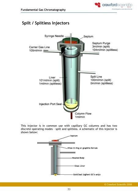
<strong>Spilt</strong> / <strong>Splitless</strong> <strong>Injectors</strong><br />
This injector is in common use with capillary GC columns and has two<br />
discrete operating modes – spilt and splitless. A schematic of this injector is<br />
shown below:<br />
53<br />
© <strong>Crawford</strong> <strong>Scientific</strong> 2008
Fundamental Gas Chromatography<br />
Split mode<br />
This mode is used where the analyte concentration in the sample is high<br />
(i.e. we are not limited in terms of the amount of analyte). As the<br />
stationary phase in capillary chromatography has a limited capacity* it is<br />
often necessary to restrict the amount of each analyte that is introduced<br />
into the column. In split mode only a fraction (determined by the user) of<br />
the vaporised sample is allowed to enter the column – the remainder being<br />
directed to waste. The ratio (or fraction) of the amount of sample that<br />
enters the column compared with the amount of sample that is discarded<br />
(via the split line – often referred to as the ‘split flow’) is called the split<br />
ratio:<br />
Split ratio = F column<br />
F split + column<br />
The split ratio will have an effect on the shape of the chromatographic<br />
peaks and the sensitivity of the analysis. Therefore it is important to ensure<br />
that both the column flow and the split flow are accurately set and verified.<br />
54<br />
© <strong>Crawford</strong> <strong>Scientific</strong> 2008
Fundamental Gas Chromatography<br />
Split injection has some drawbacks:<br />
Thermally labile analytes may decompose in the injector<br />
Discrimination processes may occur in which high boiling analytes do<br />
not reach the column with the same efficiency as low boiling analytes<br />
*capacity – is a measure of the amount of analyte which can introduced<br />
onto a stationary phase without the peak shape deteriorating<br />
significantly.<br />
Sample Discrimination<br />
Sample discrimination is caused by condensation of high boiling point<br />
components on or in the syringe needle, when placed in the hot injector.<br />
High boiling point components vaporise at a slower rate and therefore<br />
do not enter the column with the vapour plug. They may bleed from<br />
the injector over an extended period giving broad peaks or a rising<br />
baseline.<br />
The higher boiling components may also condense on or in the syringe<br />
just before it is removed from the injection port.<br />
In splitless injection the higher boiling compounds which are slowly<br />
vaporising from the liner may be ejected from the injection port as the<br />
split vent is opened to eject the excess solvent.<br />
It can be seen from the diagram below that as the carbon number increases<br />
(and sample volatility decreases), the amount of sample going onto the<br />
55<br />
© <strong>Crawford</strong> <strong>Scientific</strong> 2008
Fundamental Gas Chromatography<br />
column falls off rapidly. By the time C25 is reached, then less than 50%<br />
actually gets out of the injector and analysed.<br />
The Effect of<br />
Sample<br />
Discrimination<br />
Sample discrimination can be minimised by using either fast or slow<br />
injection.<br />
That is:<br />
Split injection<br />
Carbon no.<br />
Allow the higher boiling components to evaporate fully from the inner<br />
or outer surface of the injection syringe needle by allowing the<br />
needle to remain in the inlet longer – bringing the needle up to the<br />
temperature of the inlet (slow injection technique).<br />
Increase the speed of injection (using an autosampler) so that the<br />
injected sample is in the liquid form as it passes through the syringe<br />
and is expelled into packing within the liner – i.e. well away from the<br />
syringe outer surface. By having packing in the liner that ‘wipes’ the<br />
syringe tip as it leaves the inlet – then this will also reduce the<br />
degree of injection inlet discrimination (fast injection technique).<br />
56<br />
Normalised<br />
© <strong>Crawford</strong> <strong>Scientific</strong> 2008
Fundamental Gas Chromatography<br />
Peak width depends on Split Ratio:<br />
Low Ratio (say 1:5) High Ratio (say 1:100)<br />
Large peaks<br />
Broad peaks<br />
Column easily overloaded<br />
57<br />
Small peaks<br />
Narrow peaks<br />
Higher relative LOD<br />
Advantages and Limitations of Split <strong>Injectors</strong>:<br />
Simple to use<br />
Advantages Limitations<br />
Simple column temperature<br />
conditions<br />
Can inject high sample<br />
concentrations<br />
Protects column<br />
Cannot use for trace analysis<br />
Components can suffer thermal<br />
degradation<br />
Technique suffers from ‘sample<br />
discrimination’<br />
© <strong>Crawford</strong> <strong>Scientific</strong> 2008
Fundamental Gas Chromatography<br />
<strong>Splitless</strong> mode<br />
This mode is used where the analyte concentration is low (i.e. analyte is<br />
limited and the sample concentration is low). This injection mode uses the<br />
same hardware as split injection but the split flow is initially turned off so<br />
that the entire vaporised sample enters the inlet end of the capillary<br />
column.<br />
The sample is injected into a hot injector where it is vaporised,<br />
58<br />
© <strong>Crawford</strong> <strong>Scientific</strong> 2008
Fundamental Gas Chromatography<br />
The analyte and solvent molecules them move with the carrier gas onto the<br />
column:<br />
To help clear out the injector and ensure a stable and flat baseline in the<br />
chromatogram, the split line is turned on after a user-defined time and any<br />
components remaining in the injector are discarded to waste:<br />
59<br />
© <strong>Crawford</strong> <strong>Scientific</strong> 2008
Fundamental Gas Chromatography<br />
To help preserve the gas supply the flow down the split vent line is often<br />
reduced at a user defined time once the liner has been cleared:<br />
The peak shape, sensitivity and baseline appearance in splitless injection<br />
are determined by several parameters, which should be accurately set and<br />
verified. These parameters include:<br />
Column flow<br />
Initial oven temperature<br />
Split ‘on-time’ (the time after injection when the split flow is turned<br />
on)<br />
Split flow rate once the split flow is initiated<br />
60<br />
© <strong>Crawford</strong> <strong>Scientific</strong> 2008
Fundamental Gas Chromatography<br />
Solute Focusing<br />
<strong>Splitless</strong> injection produces broad peaks if the sample is injected at high<br />
initial column temperatures. We therefore need to use solute focussing to<br />
eliminate this.<br />
In splitless injection the split vent is closed temporary, usually for about 30<br />
seconds. Unfortunately a 30 second splitless time would give a minimum<br />
peak width of about 30 seconds if the GC were run isothermally. We<br />
therefore need to condense or focus the sample to reduce the initial peak<br />
width.<br />
Solute focusing involves re-concentrating the sample at the head of the<br />
column. An appropriate temperature programme is used. Two methods of<br />
solute focusing can be used, depending on the volatility of the solutes, and<br />
these methods are referred to as Cold Trapping and use of the Solvent<br />
Effect.<br />
Solute Focussing<br />
•Need to re-concentrate sample at front end of<br />
the column<br />
•Use appropriate temperature programme<br />
COLD TRAPPING:<br />
•Concentrates high BP components<br />
•Need column start temperature at 150 o C below BP<br />
of components<br />
SOLVENT EFFECT:<br />
•Concentrates low BP components<br />
•Need column start temperature at ~20 o C below BP<br />
of the solvent<br />
The mechanism of both Cold trapping and the Solvent Effect is demonstrated<br />
in the series of diagrams below.<br />
61<br />
© <strong>Crawford</strong> <strong>Scientific</strong> 2008
Fundamental Gas Chromatography<br />
Temperature Gradient<br />
Temperature Gradient<br />
Temperature Gradient<br />
Low boiling component<br />
Intermediate boiling component<br />
High boiling component<br />
Low boiling component<br />
Intermediate boiling component<br />
High boiling component<br />
Low boiling component<br />
Intermediate boiling component<br />
High boiling component<br />
62<br />
© <strong>Crawford</strong> <strong>Scientific</strong> 2008