Impact of leading power factor loads on synchronous ... - Cummins Inc.
Impact of leading power factor loads on synchronous ... - Cummins Inc.
Impact of leading power factor loads on synchronous ... - Cummins Inc.

Create successful ePaper yourself
Turn your PDF publications into a flip-book with our unique Google optimized e-Paper software.
Power topic #6001 | Technical informati<strong>on</strong> from <strong>Cummins</strong> Power Generati<strong>on</strong><br />
<str<strong>on</strong>g>Impact</str<strong>on</strong>g> <str<strong>on</strong>g>of</str<strong>on</strong>g> <str<strong>on</strong>g>leading</str<strong>on</strong>g> <str<strong>on</strong>g>power</str<strong>on</strong>g><br />
<str<strong>on</strong>g>factor</str<strong>on</strong>g> <str<strong>on</strong>g>loads</str<strong>on</strong>g> <strong>on</strong><br />
synchr<strong>on</strong>ous alternators<br />
> White paper
Power topic #6001 | Page 2<br />
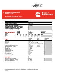
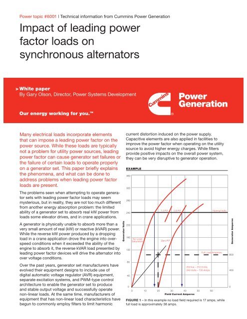
The generator set AVR m<strong>on</strong>itors generator output voltage<br />
and c<strong>on</strong>trols alternator field strength to maintain<br />
c<strong>on</strong>stant output voltage. Relatively low AVR output is<br />
required to maintain generator voltage at no load. In the<br />
figure shown, the no load exciter field current required<br />
is less than half the full load level.<br />
Filter equipment is <str<strong>on</strong>g>of</str<strong>on</strong>g>ten sized for operati<strong>on</strong> at the<br />
expected maximum load <strong>on</strong> the UPS or motor load.<br />
At light <str<strong>on</strong>g>loads</str<strong>on</strong>g> there may be excess filter capacitance,<br />
causing a <str<strong>on</strong>g>leading</str<strong>on</strong>g> <str<strong>on</strong>g>power</str<strong>on</strong>g> <str<strong>on</strong>g>factor</str<strong>on</strong>g>. Since rectifiers are<br />
comm<strong>on</strong>ly designed to ramp <strong>on</strong> from zero load to<br />
minimize load transients, <str<strong>on</strong>g>leading</str<strong>on</strong>g> <str<strong>on</strong>g>power</str<strong>on</strong>g> <str<strong>on</strong>g>factor</str<strong>on</strong>g> <str<strong>on</strong>g>loads</str<strong>on</strong>g><br />
may be imposed <strong>on</strong> the system until inductive <str<strong>on</strong>g>loads</str<strong>on</strong>g> are<br />
added to the system or the load <str<strong>on</strong>g>factor</str<strong>on</strong>g> <str<strong>on</strong>g>of</str<strong>on</strong>g> the n<strong>on</strong>linear<br />
load increases.<br />
A utility supply simply absorbs the reactive <str<strong>on</strong>g>power</str<strong>on</strong>g><br />
output because it is extremely large relative to the<br />
filter system and it has many <str<strong>on</strong>g>loads</str<strong>on</strong>g> that can c<strong>on</strong>sume<br />
this energy. With a generator set, however, the rising<br />
voltage from the <str<strong>on</strong>g>leading</str<strong>on</strong>g> <str<strong>on</strong>g>power</str<strong>on</strong>g> <str<strong>on</strong>g>factor</str<strong>on</strong>g> causes the<br />
voltage regulator to turn down and reduce alternator<br />
field strength. If the AVR turns all the way <str<strong>on</strong>g>of</str<strong>on</strong>g>f it looses<br />
c<strong>on</strong>trol <str<strong>on</strong>g>of</str<strong>on</strong>g> system voltage, which can result in sudden<br />
large increases in system voltage. The increase in<br />
voltage can result in damage to <str<strong>on</strong>g>loads</str<strong>on</strong>g>, or can cause<br />
the <str<strong>on</strong>g>loads</str<strong>on</strong>g> to fail to operate <strong>on</strong> the generator set.<br />
A UPS is designed to recognize high voltage as an<br />
abnormal and undesirable c<strong>on</strong>diti<strong>on</strong>, so it can immediately<br />
switch <str<strong>on</strong>g>of</str<strong>on</strong>g>f its rectifier. When it does that, the<br />
high voltage c<strong>on</strong>diti<strong>on</strong> is immediately relieved (because<br />
the filter is disc<strong>on</strong>nected from the generator set) and<br />
voltage returns to normal. To the observer, the generator<br />
will seem to be unable to pick up the system <str<strong>on</strong>g>loads</str<strong>on</strong>g>.<br />
Paralleling problems<br />
Generator sets that are using in isolated bus paralleling<br />
systems have particular issues with <str<strong>on</strong>g>leading</str<strong>on</strong>g> <str<strong>on</strong>g>power</str<strong>on</strong>g><br />
<str<strong>on</strong>g>factor</str<strong>on</strong>g> <str<strong>on</strong>g>loads</str<strong>on</strong>g>.<br />
When <str<strong>on</strong>g>loads</str<strong>on</strong>g> are applied to a parallel generator bus, the<br />
total load <strong>on</strong> the system can be many times larger than<br />
the capacity <str<strong>on</strong>g>of</str<strong>on</strong>g> a single generator set. The generator<br />
sets close to the bus <strong>on</strong>e at a time, so that if high<br />
<str<strong>on</strong>g>loads</str<strong>on</strong>g> (either <str<strong>on</strong>g>leading</str<strong>on</strong>g> or lagging) are applied before<br />
genset capacity is available, the generator bus can fail.<br />
With <str<strong>on</strong>g>leading</str<strong>on</strong>g> <str<strong>on</strong>g>power</str<strong>on</strong>g> <str<strong>on</strong>g>factor</str<strong>on</strong>g> <str<strong>on</strong>g>loads</str<strong>on</strong>g>, the failure mode will<br />
be due to either an over voltage c<strong>on</strong>diti<strong>on</strong> or reverse<br />
kVAR shutdown. due to either an overvoltage c<strong>on</strong>diti<strong>on</strong><br />
or due to reverse kVAR shutdown.<br />
www.cummins<str<strong>on</strong>g>power</str<strong>on</strong>g>
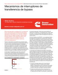
Per Unit kW<br />
Power topic #6001 | Page 3<br />
outside <str<strong>on</strong>g>of</str<strong>on</strong>g> normal range. Notice that as <str<strong>on</strong>g>power</str<strong>on</strong>g> <str<strong>on</strong>g>factor</str<strong>on</strong>g><br />
drops, the machine must be de-rated to prevent<br />
overheating. On the left quadrant, you can see that<br />
near-normal output (yellow area) can be achieved with<br />
some <str<strong>on</strong>g>leading</str<strong>on</strong>g> <str<strong>on</strong>g>power</str<strong>on</strong>g> <str<strong>on</strong>g>factor</str<strong>on</strong>g> load, in this case, down<br />
to about 0.97 <str<strong>on</strong>g>power</str<strong>on</strong>g> <str<strong>on</strong>g>factor</str<strong>on</strong>g>, <str<strong>on</strong>g>leading</str<strong>on</strong>g>. At that point, the<br />
ability to absorb additi<strong>on</strong>al kVAR quickly drops to near<br />
zero (red area), indicating that the AVR is “turning <str<strong>on</strong>g>of</str<strong>on</strong>g>f”<br />
and any level <str<strong>on</strong>g>of</str<strong>on</strong>g> reverse kVAR greater than the level<br />
shown will cause the machine to lose c<strong>on</strong>trol <str<strong>on</strong>g>of</str<strong>on</strong>g> voltage.<br />
In other words, if the machine is rated for operati<strong>on</strong> at<br />
1000 kVA and 0.8 <str<strong>on</strong>g>power</str<strong>on</strong>g> <str<strong>on</strong>g>factor</str<strong>on</strong>g> (600 kVAR rated), with<br />
a reverse kVAR level <str<strong>on</strong>g>of</str<strong>on</strong>g> 0.2 per unit (rated), you will<br />
exceed the machine’s capabilities. So, with more than<br />
120 kVAR reverse reactive <str<strong>on</strong>g>power</str<strong>on</strong>g> and <str<strong>on</strong>g>leading</str<strong>on</strong>g> <str<strong>on</strong>g>power</str<strong>on</strong>g><br />
<str<strong>on</strong>g>factor</str<strong>on</strong>g> lower than 0.97 (for most people a surprisingly<br />
low level) we have a problem.<br />
The ability <str<strong>on</strong>g>of</str<strong>on</strong>g> a generator set to absorb reactive<br />
<str<strong>on</strong>g>power</str<strong>on</strong>g> is defined by a reverse kVAR limit, not a<br />
specific <str<strong>on</strong>g>power</str<strong>on</strong>g> <str<strong>on</strong>g>factor</str<strong>on</strong>g>.<br />
ALTERNATOR CAPABILITY CURVE<br />
1.1<br />
1.0<br />
0.9<br />
0.8<br />
0.7<br />
0.6<br />
0.5<br />
0.4<br />
0.3<br />
0.2<br />
0.1<br />
0.0<br />
1.0<br />
www.cummins<str<strong>on</strong>g>power</str<strong>on</strong>g>
Power topic #6001 | Page 4<br />
About the author