

Cable Terminators and Conduit Sealing Bushings - Emerson ...
Cable Terminators and Conduit Sealing Bushings - Emerson ...
Cable Terminators and Conduit Sealing Bushings - Emerson ...

You also want an ePaper? Increase the reach of your titles
YUMPU automatically turns print PDFs into web optimized ePapers that Google loves.
RA1 <strong>Cable</strong> Connectors & <strong>Conduit</strong> <strong>Sealing</strong> <strong>Bushings</strong><br />
RA1<br />
<strong>Cable</strong> <strong>Terminators</strong><br />
General Information<br />
Purpose:<br />
<strong>Cable</strong> <strong>Terminators</strong> <strong>and</strong> <strong>Sealing</strong> Fittings are<br />
used on conduit ends <strong>and</strong> cable ends to<br />
effectively seal the cable <strong>and</strong> conduit.<br />
Where Installed:<br />
• Wherever the jacket or sheath is removed<br />
from multi-conductor cable.<br />
• Wherever it is desirable that the ends<br />
of conduit <strong>and</strong> cables be sealed against<br />
the entrance of water, damp or corrosive<br />
atmospheres, hot or cold air or dust.<br />
• Wherever it is desirable to seal the<br />
entrance of exposed cable into cabinets,<br />
switchboards or terminal boxes.<br />
Types:<br />
Four basic types are offered as described<br />
below:<br />
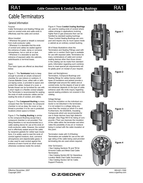
Figure 1: The Terminator body is deep<br />
enough to provide an ample compound<br />
chamber for use indoors or outdoors. A<br />
Canvas Bakelite Cover, either with or without<br />
taping cones, is provided to space <strong>and</strong><br />
protect the cables. Instead of a cover, a<br />
female thread can be furnished for use with<br />
a short nipple or a flexible conduit adapter.<br />
The Terminator is recommended for sealing<br />
the ends of multi-conductor cables <strong>and</strong> for<br />
sealing the ends of conduit, <strong>and</strong> cables.<br />
Figure 2: The Compound Bushing is more<br />
compact than the Terminator. Its compound<br />
chamber is not as deep. No cover or top<br />
thread is provided. It is for use in protected<br />
locations where space is limited.<br />
Figure 3: The <strong>Sealing</strong> Bushing is similar<br />
to the compound Bushing except that a<br />
compound chamber is not provided. This<br />
fitting therefore is not recommended as a<br />
cable sealing device for use at the ends of<br />
multi-conductor cable. However, the conduit<br />
end is effectively sealed around the cable<br />
by neoprene gaskets for rubber type insulations.<br />
It is widely used to seal the ends of<br />
conduit against moisture, dust, corrosive<br />
atmospheres <strong>and</strong> objectionable gases. It<br />
is also used to seal conduit against the<br />
entrance of warm humid air which would<br />
otherwise condense inside the conduit.<br />
Effective December, 2007<br />
Copyright 2007<br />
Figure 4: These <strong>Conduit</strong> <strong>Sealing</strong> <strong>Bushings</strong><br />
are used for sealing ends of conduit where<br />
cables emerge in applications involving<br />
higher fluid or gas pressures than can be<br />
h<strong>and</strong>led by st<strong>and</strong>ard sealing bushings.<br />
These <strong>Conduit</strong> <strong>Sealing</strong> <strong>Bushings</strong> are compact<br />
<strong>and</strong> require only as much space inside<br />
a cabinet as an ordinary conduit bushing.<br />
All of these illustrations show the<br />
<strong>Terminators</strong> <strong>and</strong> <strong>Sealing</strong> Fittings used with<br />
cable run in conduit. Each type is available<br />
for use with exposed cable. <strong>Terminators</strong> for<br />
many combinations of cable <strong>and</strong> conduit<br />
sealing devices other than those shown<br />
in the catalog can be made from st<strong>and</strong>ard<br />
parts. Information regarding such combinations<br />
to meet special job requirements will<br />
be gladly given on receipt of your request.<br />
Water <strong>and</strong> Raintightness:<br />
<strong>Terminators</strong>, Compound <strong>Bushings</strong> <strong>and</strong><br />
<strong>Sealing</strong> fittings for cables having rubber<br />
types of insulations <strong>and</strong> jackets provide a<br />
watertight seal around the cables <strong>and</strong> at<br />
conduit ends, but the degree of seal at cabinet<br />
entrances depends on the type of cable<br />
entrance used. We invite inquiry regarding<br />
special sealing problems not covered in this<br />
catalog.<br />
Voltage Ratings:<br />
Since the insulation on the individual conductor<br />
is not disturbed in the terminator,<br />
it is not subject to a voltage rating any<br />
more than the conduit on which it is used.<br />
Furthermore, the DOZSEAL Insulating<br />
Compounds which are recommended for<br />
use in these devices have high dielectric<br />
strength. (See Page RA15 for listing of compounds.)<br />
Their use improves the insulation<br />
of the cable within the terminator <strong>and</strong> eliminates<br />
the possibility of any air or moisture<br />
being in contact with the cable insulation at<br />
this point.<br />
Termination made with O-Z/Gedney<br />
<strong>Terminators</strong> are suitable for use at the voltage<br />
rating of the cable being used provided<br />
terminating kits are used where required.<br />
Other <strong>Terminators</strong>:<br />
• See Catalog Sections TA <strong>and</strong> TB for<br />
Armored <strong>Cable</strong> <strong>and</strong> Metal Clad <strong>Cable</strong><br />
<strong>Terminators</strong>.<br />
• See Catalog Section BC for Hazardous<br />
Location Metal Clad <strong>Cable</strong> <strong>Terminators</strong>.<br />
• See Catalog Section QA for <strong>Cable</strong><br />
Support Products.<br />
Figure 1<br />
Figure 2<br />
Figure 3<br />
Figure 4<br />
800-621-1506<br />
www.o-zgedney.com
RA2 <strong>Cable</strong> Connectors & <strong>Conduit</strong> <strong>Sealing</strong> <strong>Bushings</strong><br />
RA2<br />
<strong>Cable</strong> <strong>Terminators</strong><br />
Assembly Procedure<br />
Blank <strong>Sealing</strong> <strong>Bushings</strong> <strong>and</strong> <strong>Terminators</strong><br />
Containing Discs:<br />
There are many types of fittings containing<br />
Bakelite discs <strong>and</strong> O-rings which can<br />
be safely drilled in the field by following<br />
our detailed instructions. “These fittings will<br />
perform satisfactorily only when properly<br />
machined to the actual dimensions for<br />
the specific O.D. of cable used. Detailed<br />
instruction sheets containing layout data<br />
<strong>and</strong> special assembly procedures are supplied<br />
with blank fittings. Failure to comply<br />
may result in compound leakage <strong>and</strong>/or loss<br />
of seal around cable. O-Z/Gedney is not<br />
responsible for any field machined or modified<br />
fittings.”<br />
Other <strong>Terminators</strong>:<br />
• See Catalog Sections TA <strong>and</strong> TB for<br />
Armored <strong>Cable</strong> <strong>and</strong> Metal Clad <strong>Cable</strong><br />
<strong>Terminators</strong>.<br />
• See Catalog Section BC for Hazardous<br />
Location Metal Clad <strong>Cable</strong> <strong>Terminators</strong>.<br />
• See Catalog Section QA for <strong>Cable</strong><br />
Support Products.<br />
Effective December, 2007<br />
Copyright 2007<br />
The basic principles used throughout the line of O-Z/Gedney <strong>Terminators</strong> covering their<br />
use with Rubber Covered <strong>Cable</strong>s are clearly illustrated in this assembly.<br />
Seating<br />
Disc<br />
Existing<br />
<strong>Conduit</strong><br />
1 After cables are prepared, Bakelite seating<br />
disc with properly drilled holes is slipped<br />
over cables <strong>and</strong> set into the conduit.<br />
Neoprene<br />
Ring<br />
2 Neoprene rings, are placed around the<br />
cables <strong>and</strong> set into recesses in the sealing<br />
disc.<br />
Pressure<br />
Disk<br />
3 A Canvas Bakelite pressure disc is<br />
passed over the cables <strong>and</strong> set on top of<br />
the neoprene rings, holding them firmly in<br />
place.<br />
Body<br />
4 The body is then screwed directly on the<br />
conduit, clamping the discs <strong>and</strong> applying<br />
pressure to the neoprene rings.<br />
<strong>Sealing</strong><br />
Compound<br />
5 Compound is heated to the proper temperature<br />
<strong>and</strong> the body filled to the height of<br />
the set screws, making a complete seal.<br />
Top<br />
Cover<br />
Set<br />
Screws<br />
6 Before compound sets, Canvas Bakelite<br />
top cover is passed over the conductors,<br />
pushed down into the hot compound <strong>and</strong><br />
secured by set screws.<br />
800-621-1506<br />
www.o-zgedney.com
RA3 <strong>Cable</strong> Connectors & <strong>Conduit</strong> <strong>Sealing</strong> <strong>Bushings</strong> RA3<br />
<strong>Cable</strong> <strong>Terminators</strong><br />
With Compound Chamber For Threaded Rigid <strong>Conduit</strong><br />
Type CRC<br />
With Top Cover<br />
Type CRN<br />
With Top Thread<br />
Use:<br />
To effectively seal one or more single or<br />
multiple conductor cables <strong>and</strong> the conduit<br />
against the entrance of water, damp or corrosive<br />
atmospheres, hot or cold air or dust.<br />
Features:<br />
• For rubber or plastic insulated cables in<br />
rigid conduit.<br />
• Provides an ample sealing compound<br />
chamber for use indoors or outdoors.<br />
• For applications involving IMC, EMT or<br />
PVC conduit, a short nipple of rigid conduit<br />
should be used entering the bottom<br />
threaded hub.<br />
• For <strong>Sealing</strong> Compound, see page RA15.<br />
<strong>Sealing</strong> Compound is not included <strong>and</strong><br />
must be ordered separately.<br />
• Can be field-drilled, see page RA2.<br />
• For voltage ratings, see page RA1.<br />
Material/Finish:<br />
Body: Malleable or Ductile Iron Casting<br />
with Hot Dip Galvanized finish.<br />
<strong>Sealing</strong> Disc: Canvas Bakelite<br />
Options:<br />
• Body available in Cast Aluminum. Add<br />
suffix “A” to st<strong>and</strong>ard catalog number.<br />
• Fittings can be furnished for more than<br />
four wires or wires of varying sizes.<br />
• Lay-In-Lug Grounding Lug can be<br />
mounted on Terminator Body, see page<br />
QA14.<br />
• Type CRC terminators are available with<br />
tapping cones for sealing rubber or plastic<br />
insulated cables.<br />
• Due to the possibility of Magnetic<br />
Induction Heating, a single alternating current<br />
conductor should not be used in iron<br />
fittings. Specify optional Aluminum material,<br />
see above.<br />
• Contact your local representative for price<br />
<strong>and</strong> availability on above options.<br />
Third Party Certification:<br />
CSA Certified: 11584<br />
TO ORDER SPECIFY:<br />
1 Catalog Number<br />
2 Number of cables<br />
3 Diameter over insulation of each cable<br />
Effective December, 2007<br />
Copyright 2007<br />
TYPE CRC<br />
Max. Diameter of Wire Permitted - Inches Dim. in Inches Approx.<br />
<strong>Conduit</strong> 1* 2 3 4 Catalog Max. Overall Compound<br />
Size Wire Wires Wires Wires Number Dia. Height Reqd. (Pints)<br />
11 ⁄4” 1.02 .55 .50 .44 CRC-125 21 ⁄4 31 ⁄8<br />
11 ⁄2” 1.20 .63 .59 .51 CRC-150 23 ⁄8 31 ⁄4<br />
2” 1.53 .81 .73 .65 CRC-200 3 33 ⁄4<br />
21 ⁄2” 1.83 .97 .93 .78 CRC-250 31 ⁄2 41 ⁄4<br />
3” 2.28 1.21 1.16 .97 CRC-300 41 ⁄4 43 ⁄4<br />
3<br />
⁄4<br />
31 ⁄2” 2.65 1.40 1.34 1.12 CRC-350 43 ⁄4 51 ⁄8 1<br />
4” 3.00 1.58 1.52 1.27 CRC-400 53 ⁄8 57 ⁄8 11 ⁄2<br />
5” 3.75 1.99 1.91 1.60 CRC-500 61 ⁄2 61 ⁄2 23 ⁄4<br />
6” 4.50 2.39 2.30 1.92 CRC-600 75 ⁄8 67 ⁄8 4<br />
TYPE CRN<br />
Existing<br />
<strong>Conduit</strong><br />
Type CRC Type CRN<br />
Max. Diameter of Wire Permitted - Inches Dim. in Inches Approx.<br />
<strong>Conduit</strong> 1* 2 3 4 Catalog Top Th’d. Max. Overall Compound<br />
Size Wire Wires Wires Wires Number Pipe Size Dia. Height Reqd. (Pints)<br />
11 ⁄4” 1.02 .55 .50 .44 CRN-125 11 ⁄4 21 ⁄4 31 ⁄8<br />
11 ⁄2” 1.20 .63 .59 .51 CRN-150 11 ⁄2 23 ⁄8 31 ⁄4<br />
2” 1.53 .81 .73 .65 CRN-200 2 3 33 ⁄4<br />
21 ⁄2” 1.83 .97 .93 .78 CRN-250 21 ⁄2 31 ⁄2 41 ⁄4<br />
3” 2.28 1.21 1.16 .97 CRN-300 3 41 ⁄4 43 ⁄4<br />
3<br />
⁄4<br />
31 ⁄2” 2.65 1.40 1.34 1.12 CRN-350 31 ⁄2 43 ⁄4 51 ⁄8 1<br />
4” 3.00 1.58 1.52 1.27 CRN-400 4 53 ⁄8 57 ⁄8 11 ⁄2<br />
5” 3.75 1.99 1.91 1.60 CRN-500 5 61 ⁄2 61 ⁄2 23 ⁄4<br />
6” 4.50 2.39 2.30 1.92 CRN-600 6 6 67 ⁄8 4<br />
1 ⁄8<br />
1 ⁄8<br />
1 ⁄4<br />
1 ⁄2<br />
1 ⁄8<br />
1 ⁄8<br />
1 ⁄4<br />
1 ⁄2<br />
800-621-1506<br />
www.o-zgedney.com
RA4 <strong>Cable</strong> Connectors & <strong>Conduit</strong> <strong>Sealing</strong> <strong>Bushings</strong> RA4<br />
Wire Armor <strong>Cable</strong> <strong>Terminators</strong><br />
For Exposed Wire Armor <strong>Cable</strong><br />
Type CRA<br />
With Compound Chamber<br />
Use:<br />
To effectively seal a single or multiple<br />
conductor cable with exposed wire armor<br />
against the entrance of water, damp or<br />
corrosive atmospheres, hot or cold air or<br />
dust.<br />
Features:<br />
• Supplied with Locknut <strong>and</strong> Insulated<br />
Bushing for enclosure knockout entrance.<br />
• Provides an ample sealing compound<br />
chamber for use indoors or outdoors.<br />
• For <strong>Sealing</strong> Compound, see page RA15.<br />
<strong>Sealing</strong> Compound is not included <strong>and</strong> must<br />
be ordered separately.<br />
• Can be field-drilled, see page RA2.<br />
• For voltage ratings, see page RA1.<br />
Material/Finish:<br />
Body: Malleable or Ductile Iron Casting<br />
with Hot Dip Galvanized finish.<br />
<strong>Sealing</strong> Disc: Canvas Bakelite<br />
Options:<br />
• Body available in Cast Aluminum. Add<br />
suffix “A” to st<strong>and</strong>ard catalog number.<br />
• Due to the possibility of Magnetic Induction<br />
Heating, a single alternating current conductor<br />
should not be used in iron fittings.<br />
Specify optional Aluminum material, see<br />
above.<br />
• Lay-In-Lug Grounding Lug can be mounted<br />
on Terminator Body, see page QA14.<br />
• Contact your local representative for price<br />
<strong>and</strong> availability on above options.<br />
TO ORDER SPECIFY:<br />
1 Catalog Number<br />
2 Diameter Over Armor<br />
3 Diameter Over Jacket Under Armor<br />
Effective December, 2007<br />
Copyright 2007<br />
Type CRA<br />
Existing<br />
<strong>Cable</strong><br />
Dimensions in Inches<br />
<strong>Cable</strong> Range Knockout Height Height Approx.<br />
Dia. Over Armor Size Catalog Dia. Dia. Outside Inside Compound<br />
Min. Max. Required Number Body <strong>Bushings</strong> Box Box Reqd. Pints<br />
.89 1.31 1 1 ⁄2 CRA-150 2 3 ⁄8 2 1 ⁄8 4 3 ⁄4 3 ⁄4 1 ⁄4<br />
1.32 1.66 2 CRA-200 3 2 3 ⁄4 5 1 ⁄4 7 ⁄8 1 ⁄2<br />
1.67 2.40 3 CRA-300 4 1 ⁄4 4 6 1 ⁄2 1 1 1 ⁄4<br />
2.41 3.13 4 CRA-400 5 3 ⁄8 5 7 5 ⁄8 1 1 ⁄8 2 3 ⁄4<br />
3.14 3.88 5 CRA-500 6 1 ⁄2 6 1 ⁄4 8 3 ⁄8 1 1 ⁄4 4 1 ⁄2<br />
800-621-1506<br />
www.o-zgedney.com
RA5 <strong>Cable</strong> Connectors & <strong>Conduit</strong> <strong>Sealing</strong> <strong>Bushings</strong> RA5<br />
<strong>Cable</strong> <strong>Terminators</strong><br />
For Threaded Rigid <strong>Conduit</strong> - Mounted Horizontally<br />
Type CRH<br />
With Compound Chamber<br />
Use:<br />
To effectively seal one or more single or<br />
multiple conductor cables. Prevents the<br />
escape of compound, regardless of its<br />
position.<br />
Features:<br />
• The head end of the terminator is<br />
equipped with a pressure bushing which<br />
compresses neoprene rings placed around<br />
the cables between two Canvas Bakelite<br />
Discs. The Type CRH is similar in interior<br />
construction to the Type CRC on Page RA3<br />
of this section.<br />
• For rubber or plastic insulated cables in<br />
rigid conduit.<br />
• Provides an ample sealing compound<br />
chamber for use indoors or outdoors.<br />
• For applications involving IMC, EMT or<br />
PVC conduit, a short nipple of rigid conduit<br />
should be used entering the bottom<br />
threaded hub.<br />
• For <strong>Sealing</strong> Compound, see page RA15.<br />
<strong>Sealing</strong> Compound is not included <strong>and</strong><br />
must be ordered separately.<br />
• Can be field-drilled, see page RA2.<br />
Material/Finish:<br />
Body: Malleable or Ductile Iron Casting<br />
with Hot Dip Galvanized finish.<br />
<strong>Sealing</strong> Disc: Canvas Bakelite<br />
Options:<br />
• Body available in Cast Aluminum. Add suffix<br />
“A” to st<strong>and</strong>ard catalog number.<br />
• Fittings can be furnished for more than<br />
four wires or wires of varying sizes.<br />
• Due to the possibility of Magnetic<br />
Induction Heating, a single alternating current<br />
conductor should not be used in iron<br />
fittings. Specify optional Aluminum material,<br />
see above.<br />
• Lay-In-Lug Grounding Lug can be<br />
mounted on Terminator Body, see page<br />
QA14.<br />
• Contact your local representative for price<br />
<strong>and</strong> availability on above options.<br />
Third Party Certification:<br />
CSA Certified: 11584<br />
TO ORDER SPECIFY:<br />
1 Catalog Number<br />
2 Number of conductors<br />
3 Diameter over insulation of each<br />
conductor<br />
Effective December, 2007<br />
Copyright 2007<br />
Existing<br />
<strong>Conduit</strong><br />
Vent Plug<br />
Filling Plug<br />
Type CRH<br />
Max. Diameter of Wire Permitted - Inches Dim. in Inches Approx.<br />
<strong>Conduit</strong> 1* 2 3 4 Catalog Maximum Overall Compound Reqd.<br />
Size Wire Wires Wires Wires Number Diameter Height Pints<br />
1 1 ⁄4” 1.02 .58 .50 .44 CRH-125 2 3 ⁄8 3 3 ⁄8 1 ⁄8<br />
1 1 ⁄2” 1.20 .63 .59 .51 CRH-150 2 5 ⁄8 3 1 ⁄2 1 ⁄8<br />
2” 1.53 .81 .73 .65 CRH-200 3 3 ⁄8 4 1 ⁄8 1 ⁄4<br />
2 1 ⁄2” 1.83 .97 .93 .78 CRH-250 3 7 ⁄8 4 5 ⁄8 1 ⁄2<br />
3” 2.28 1.21 1.16 .97 CRH-300 3 7 ⁄8 4 5 ⁄8 1 ⁄2<br />
3 1 ⁄2” 2.65 1.40 1.34 1.12 CRH-350 5 1 ⁄8 5 5 ⁄8 1<br />
4” 3.00 1.58 1.52 1.27 CRH-400 5 3 ⁄4 6 3 ⁄8 1 1 ⁄2<br />
5” 3.75 1.99 1.91 1.60 CRH-500 6 3 ⁄4 6 7 ⁄8 2 3 ⁄4<br />
6” 4.50 2.39 2.30 1.92 CRH-600 7 7 ⁄8 7 3 ⁄8 4<br />
800-621-1506<br />
www.o-zgedney.com
RA6 <strong>Cable</strong> Connectors & <strong>Conduit</strong> <strong>Sealing</strong> <strong>Bushings</strong> RA6<br />
<strong>Cable</strong> <strong>Terminators</strong><br />
For Threaded Rigid <strong>Conduit</strong> Compound Chamber with Top <strong>and</strong> Taping Cones<br />
Type DTC - St<strong>and</strong>ard Size<br />
Type DRC - Exp<strong>and</strong>ed Size<br />
Use:<br />
• To effectively seal one or more conductors<br />
<strong>and</strong> the conduit against the entrance of<br />
water, damp or corrosive atmospheres, hot<br />
or cold air or dust.<br />
• Type DTC is used where the wires<br />
installed in the conduit are small enough to<br />
provide proper space between the cones<br />
for taping, in a Terminator the same size as<br />
the conduit.<br />
• Type DRC is used where larger wires are<br />
installed in the same size conduit. With the<br />
larger wires, enough space must be allowed<br />
between the cones for taping. This condition<br />
calls for a special adapter with a larger<br />
body <strong>and</strong> cover.<br />
Features:<br />
• For rubber or plastic insulated cables in<br />
rigid conduit.<br />
• Specially designed Canvas Bakelite cover<br />
with Taping Cones.<br />
• Provides an ample sealing compound<br />
chamber for use indoors or outdoors.<br />
• For applications involving IMC, EMT<br />
or PVC conduit, a short nipple of rigid<br />
conduit should be used entering the bottom<br />
threaded hub.<br />
• For <strong>Sealing</strong> Compound, see page RA15.<br />
<strong>Sealing</strong> Compound is not included <strong>and</strong><br />
must be ordered separately.<br />
• Can be field-drilled, see page RA2.<br />
• For voltage ratings, see page RA1.<br />
Material/Finish:<br />
Body: Malleable or Ductile Iron Casting<br />
with Hot Dip Galvanized finish.<br />
<strong>Sealing</strong> Disc: Canvas Bakelite<br />
Options:<br />
• Body available in Cast Aluminum. Add<br />
suffix “A” to st<strong>and</strong>ard catalog number.<br />
• Fittings can be furnished for more than<br />
four wires or wires of varying sizes.<br />
• Due to the possibility of Magnetic<br />
Induction Heating, a single alternating<br />
current conductor should not be used in<br />
iron fittings. Specify optional Aluminum<br />
material, see above.<br />
• Lay-In-Lug Grounding Lug can be<br />
mounted on Terminator Body, see page<br />
QA14.<br />
• Contact your local representative for price<br />
<strong>and</strong> availability on above options.<br />
Third Party Certification:<br />
CSA Certified: 11584<br />
TO ORDER SPECIFY:<br />
1 Catalog Number<br />
2 Number of cables<br />
3 Diameter over insulation of each cable<br />
Effective December, 2007<br />
Copyright 2007<br />
Existing<br />
<strong>Conduit</strong><br />
Existing<br />
<strong>Conduit</strong><br />
Type DTC Type DRC<br />
Max. Diameter of Wire Permitted - Inches Dim. in Inches Approx.<br />
<strong>Conduit</strong> 1* 2 3 4 Catalog Maximum Overall Compound Reqd.<br />
Size Wire Wires Wires Wires Number Diameter Height Pints<br />
1 1 ⁄2” 1.20 .47 .44 .34 DTC-150 2 3 ⁄8 4 1 ⁄8<br />
1 1 ⁄2” 1.34 .63 .59 .51 DRC-150 3 5 3 ⁄4 1 ⁄4<br />
2” 1.53 .63 .59 .51 DTC-200 3 4 3 ⁄4 1 ⁄4<br />
2” 1.63 .81 .78 .65 DRC-200 3 1 ⁄2 6 3 ⁄8 1 ⁄2<br />
2 1 ⁄2” 1.83 .81 .78 .65 DTC-250 3 1 ⁄2 5 3 ⁄8 1 ⁄2<br />
2 1 ⁄2” 2.00 .97 .93 .78 DRC-250 4 1 ⁄4 7 3 ⁄8 3 ⁄4<br />
3” 2.28 .97 .93 .78 DTC-300 4 1 ⁄4 6 3 ⁄4<br />
3” 2.42 1.21 1.16 .97 DRC-300 4 3 ⁄4 8 1 ⁄8 1<br />
3 1 ⁄2” 2.65 1.25 1.16 .97 DTC-350 4 3 ⁄4 6 5 ⁄8 1<br />
3 1 ⁄2” 2.85 1.40 1.34 1.12 DRC-350 5 3 ⁄8 9 1 ⁄8 1 1 ⁄2<br />
4” 3.00 1.40 1.34 1.12 DTC-400 5 3 ⁄4 7 5 ⁄8 1 1 ⁄2<br />
4” 3.15 1.58 1.52 1.27 DRC-400 5 7 ⁄4 9 1 ⁄2 2<br />
5” 3.75 1.81 1.71 1.50 DTC-500 6 1 ⁄2 8 1 ⁄4 2 3 ⁄4<br />
5” 3.90 1.99 1.91 1.60 DRC-500 7 5 ⁄8 10 3 ⁄4 4<br />
6” 4.50 2.38 2.00 1.75 DTC-600 7 5 ⁄8 8 7 ⁄8 4<br />
800-621-1506<br />
www.o-zgedney.com
RA7 <strong>Cable</strong> Connectors & <strong>Conduit</strong> <strong>Sealing</strong> <strong>Bushings</strong> RA7<br />
<strong>Conduit</strong> Compound <strong>Bushings</strong><br />
For Ends of Threaded Rigid <strong>Conduit</strong><br />
Type FR<br />
Use:<br />
To effectively seal one or more single<br />
or multiple conductor cables against the<br />
entrance of water, damp or corrosive<br />
atmospheres, hot or cold air or dust.<br />
Features:<br />
• For rubber or plastic insulated cables in<br />
rigid conduit.<br />
• Provides an ample sealing compound<br />
chamber for use indoors or outdoors.<br />
• For <strong>Sealing</strong> Compound, see page RA15.<br />
<strong>Sealing</strong> Compound is not included <strong>and</strong><br />
must be ordered separately.<br />
• For applications involving IMC, EMT<br />
or PVC conduit, a short nipple of rigid<br />
conduit should be used entering the<br />
bottom threaded hub.<br />
• For voltage ratings, see page RA1.<br />
• Lay-In-Lug Grounding Lug can be<br />
mounted on Terminator Body, see page<br />
QA14.<br />
• Can be field-drilled, see page RA2.<br />
Material/Finish:<br />
Bodies 1” & 1 1 ⁄4” are Steel with Zinc<br />
Electroplate. Larger Bodes are Malleable or<br />
Ductile Iron with Hot Dip Galvanized finish.<br />
<strong>Sealing</strong> Discs are Canvas Bakelite.<br />
Options:<br />
• Bodies are available in Aluminum. Add<br />
suffix “A” to st<strong>and</strong>ard catalog number.<br />
• Steel Bodies 1” & 1 1 ⁄4” are available with<br />
Hot Dip Galvanized Finish.<br />
• Fittings can be furnished for more than<br />
four wires or wires of varying sizes.<br />
• Due to the possibility of Magnetic<br />
Induction Heating, a single alternating<br />
current conductor should not be used in<br />
iron fittings. Specify optional Aluminum<br />
material, see above.<br />
• Contact your local representative for price<br />
<strong>and</strong> availability on above options.<br />
Third Party Certification:<br />
CSA Certified: 11584<br />
TO ORDER SPECIFY:<br />
1 Catalog Number<br />
2 Number of cables<br />
3 Diameter over insulation of each cable<br />
Effective December, 2007<br />
Copyright 2007<br />
Existing<br />
<strong>Conduit</strong><br />
Type FR<br />
Approx.<br />
Max. Diameter of Wire Permitted - Inches Dim. in Inches Compound<br />
<strong>Conduit</strong> 1* 2 3 4 Catalog Max. Overall Required<br />
Size Wire Wires Wires Wires Number Dia. Height Pints<br />
1” .78 .38 .34 .31 FR-100 1 3 ⁄4 1 5 ⁄8 1 ⁄20<br />
1 1 ⁄4” 1.02 .55 .50 .44 FR-125 2 1 ⁄8 1 3 ⁄4 1 ⁄20<br />
1 1 ⁄2” 1.20 .63 .59 .51 FR-150 2 3 ⁄8 1 7 ⁄8 1 ⁄8<br />
2” 1.53 .81 .73 .65 FR-200 3 2 1 ⁄6<br />
2 1 ⁄2” 1.83 .97 .93 .78 FR-250 3 5 ⁄8 2 1 ⁄2 1 ⁄3<br />
3” 2.28 1.21 1.16 .97 FR-300 4 1 ⁄8 2 5 ⁄8 1 ⁄2<br />
3 1 ⁄2” 2.65 1.40 1.34 1.12 FR-350 4 5 ⁄8 2 5 ⁄8 1 ⁄2<br />
4” 3.00 1.58 1.52 1.27 FR-400 5 1 ⁄8 2 5 ⁄8 2 ⁄3<br />
5” 3.75 1.99 1.91 1.60 FR-500 6 3 ⁄4 3 1 ⁄8 1<br />
6” 4.50 2.39 2.30 1.92 FR-600 7 5 ⁄8 3 3 ⁄8 1 1 ⁄12<br />
800-621-1506<br />
www.o-zgedney.com
RA8 <strong>Cable</strong> Connectors & <strong>Conduit</strong> <strong>Sealing</strong> <strong>Bushings</strong> RA8<br />
Cabinet Compound <strong>Bushings</strong><br />
For Threaded Rigid <strong>Conduit</strong>s Entering Cabinets<br />
Type HRK<br />
Use:<br />
To effectively seal one or more single<br />
or multiple conductor cables against the<br />
entrance of water, damp or corrosive<br />
atmospheres, hot or cold air or dust.<br />
Features:<br />
• For rubber or plastic insulated cables in<br />
rigid conduit.<br />
• Provides an ample sealing compound<br />
chamber for use indoors or outdoors.<br />
• For <strong>Sealing</strong> Compound, see page RA15.<br />
<strong>Sealing</strong> Compound is not included <strong>and</strong><br />
must be ordered separately.<br />
• Supplied with two locknuts for cabinets up<br />
to 1 ⁄4” thick.<br />
• For applications involving IMC, EMT<br />
or PVC conduit, a short nipple of rigid<br />
conduit should be used entering the<br />
bottom threaded hub.<br />
• For voltage ratings, see page RA1.<br />
• Lay-In-Lug Grounding Lug can be<br />
mounted on Terminator Body, see page<br />
QA14.<br />
• Can be field-drilled, see page RA2.<br />
Material/Finish:<br />
Bodies 1” & 1 1 ⁄4” are Steel with Zinc<br />
Electroplate. Larger Bodes are Malleable or<br />
Ductile Iron with Hot Dip Galvanized finish.<br />
Locknuts are Steel or Malleable Iron with<br />
Zinc Electroplate. <strong>Sealing</strong> Discs are Canvas<br />
Bakelite.<br />
Options:<br />
• Bodies are available in Aluminum. Add<br />
suffix “A” to st<strong>and</strong>ard catalog number.<br />
• Bodies 1” & 1 1 ⁄4” are available with Hot Dip<br />
Galvanized Finish.<br />
• Fittings can be furnished for more than<br />
four wires or wires of varying sizes.<br />
• Due to the possibility of Magnetic<br />
Induction Heating, a single alternating<br />
current conductor should not be used in<br />
iron fittings. Specify optional Aluminum<br />
material, see above.<br />
• Contact your local representative for price<br />
<strong>and</strong> availability on above options.<br />
Third Party Certification:<br />
CSA Certified: 11584<br />
TO ORDER SPECIFY:<br />
1 Catalog Number<br />
2 Number of cables<br />
3 Diameter over insulation of each cable<br />
Effective December, 2007<br />
Copyright 2007<br />
Existing<br />
Cabinet<br />
Existing<br />
<strong>Conduit</strong><br />
Type HRK<br />
Approx.<br />
Max. Diameter of Wire Permitted - Inches Dimensions in Inches Compound<br />
<strong>Conduit</strong> 1* 2 3 4 Catalog Max. “A” Required<br />
Size Wire Wires Wires Wires Number Dia. Min. “B” Pints<br />
1” .78 .38 .34 .31 HRK-100 1 3 ⁄4 1 1 1 ⁄8 1 ⁄20<br />
1 1 ⁄4” 1.02 .55 .50 .44 HRK-125 2 3 ⁄8 1 1 1 ⁄4 1 ⁄20<br />
1 1 ⁄2” 1.20 .63 .59 .51 HRK-150 2 5 ⁄8 1 1 1 ⁄4 1 ⁄8<br />
2” 1.53 .81 .73 .65 HRK-200 3 1 ⁄8 1 1 ⁄8 1 1 ⁄2 1 ⁄6<br />
2 1 ⁄2” 1.83 .97 .93 .78 HRK-250 3 5 ⁄8 1 3 ⁄8 1 3 ⁄4 1 ⁄3<br />
3” 2.28 1.21 1.16 .97 HRK-300 4 3 ⁄8 1 1 ⁄2 1 7 ⁄8 1 ⁄2<br />
3 1 ⁄2” 2.65 1.40 1.34 1.12 HRK-350 5 1 1 ⁄2 1 7 ⁄8 1 ⁄2<br />
4” 3.00 1.58 1.52 1.27 HRK-400 5 1 ⁄2 1 1 ⁄2 1 7 ⁄8 2 ⁄3<br />
5” 3.75 1.99 1.91 1.60 HRK-500 6 7 ⁄8 1 5 ⁄8 2 3 ⁄8 1<br />
6” 4.50 2.39 2.30 1.92 HRK-600 7 5 ⁄8 1 3 ⁄4 2 1 ⁄2 1 1 ⁄12<br />
800-621-1506<br />
www.o-zgedney.com
RA9 <strong>Cable</strong> Connectors & <strong>Conduit</strong> <strong>Sealing</strong> <strong>Bushings</strong><br />
RA9<br />
Cabinet Compound <strong>Bushings</strong><br />
For Exposed <strong>Cable</strong>s Entering Cabinets<br />
Type HRE<br />
Use:<br />
To effectively seal one or more single<br />
or multiple conductor cables against the<br />
entrance of water, damp or corrosive<br />
atmospheres, hot or cold air or dust.<br />
Features:<br />
• For rubber or plastic insulated cables.<br />
• Provides an ample sealing compound<br />
chamber for use indoors or outdoors.<br />
• For <strong>Sealing</strong> Compound, see page RA15.<br />
<strong>Sealing</strong> Compound is not included <strong>and</strong> must<br />
be ordered separately.<br />
• Supplied with a locknut <strong>and</strong> neoprene<br />
sealing ring for cabinets up to 1 ⁄4” thick.<br />
• For voltage ratings, see page RA1.<br />
• Lay-In-Lug Grounding Lug can be<br />
mounted on Terminator Body, see page<br />
QA14.<br />
• Can be field-drilled, see page RA2.<br />
Material/Finish:<br />
Bodies 1” & 1 1 ⁄4” are Steel with Zinc<br />
Electroplate. Larger Bodes are Malleable<br />
or Ductile Iron with Hot Dip Galvanized finish.<br />
Locknut is Steel or Malleable Iron with<br />
Zinc Electroplate. <strong>Sealing</strong> Discs are Canvas<br />
Bakelite.<br />
Options:<br />
• Bodies are available in Aluminum. Add<br />
suffix “A” to st<strong>and</strong>ard catalog number.<br />
• Bodies 1” & 1 1 ⁄4” are available with Hot Dip<br />
Galvanized Finish.<br />
• Fittings can be furnished for more than<br />
four wires or wires of varying sizes.<br />
• Due to the possibility of Magnetic Induction<br />
Heating, a single alternating<br />
current conductor should not be used in iron<br />
fittings. Specify optional Aluminum material,<br />
see above.<br />
• Contact your local representative for price<br />
<strong>and</strong> availability on above options.<br />
Third Party Certification:<br />
CSA Certified: 11584<br />
TO ORDER SPECIFY:<br />
1 Catalog Number<br />
2 Number of conductors<br />
3 Diameter over insulation of each<br />
conductor<br />
Effective December, 2007<br />
Copyright 2007<br />
Existing Cabinet<br />
up to 1 ⁄4” thick<br />
Type HRE<br />
Approx.<br />
Max. Dia. of Wire Permitted - Inches Dim. in Inches Compound<br />
1* 2 3 4 Knockout Catalog Max. Overall Required<br />
Wire Wires Wires Wires Size Number Dia. Height Pints<br />
.78 .38 .34 .31 1” HRE-100 1 3 ⁄4 2 1 ⁄8 1 ⁄20<br />
1.02 .55 .50 .44 1 1 ⁄4” HRE-125 2 3 ⁄8 2 1 ⁄4 1 ⁄20<br />
1.20 .63 .59 .51 1 1 ⁄2” HRE-150 2 5 ⁄8 2 1 ⁄4 1 ⁄8<br />
1.53 .81 .73 .65 2” HRE-200 3 1 ⁄8 2 5 ⁄8 1 ⁄6<br />
1.83 .97 .93 .78 2 1 ⁄2” HRE-250 3 5 ⁄8 3 1 ⁄8 1 ⁄3<br />
2.28 1.21 1.16 .97 3” HRE-300 4 3 ⁄8 3 3 ⁄8 1 ⁄2<br />
2.65 1.40 1.34 1.12 3 1 ⁄2” HRE-350 5 3 3 ⁄8 1 ⁄2<br />
3.00 1.58 1.52 1.27 4” HRE-400 5 1 ⁄2 3 3 ⁄8 2 ⁄3<br />
3.75 1.99 1.91 1.60 5” HRE-500 6 7 ⁄8 4 1<br />
4.50 2.39 2.30 1.92 6” HRE-600 7 5 ⁄8 4 1 ⁄4 1 1 ⁄2<br />
800-621-1506<br />
www.o-zgedney.com
RA10 <strong>Cable</strong> Connectors & <strong>Conduit</strong> <strong>Sealing</strong> <strong>Bushings</strong><br />
RA10<br />
<strong>Cable</strong> Support Compound <strong>Bushings</strong><br />
For Exposed <strong>Cable</strong>s Entering Cabinets - with pOZi-grip ® Wedging Plug<br />
Type HPE<br />
Use:<br />
Provides cable support while effectively<br />
sealing one or more single or multiple<br />
conductor cables against the entrance of<br />
water, damp or corrosive atmospheres, hot<br />
or cold air or dust.<br />
Features:<br />
• For rubber or plastic insulated cables.<br />
• Supports a vertical length of cable per<br />
NEC Section 300.19(A). Refer to page QA1<br />
for details.<br />
• Provides an ample sealing compound<br />
chamber for use indoors or outdoors.<br />
• For <strong>Sealing</strong> Compound, see page RA15.<br />
<strong>Sealing</strong> Compound is not included <strong>and</strong> must<br />
be ordered separately.<br />
• Supplied with a locknut <strong>and</strong> neoprene<br />
sealing ring for cabinets up to 1 ⁄4” thick.<br />
• For voltage ratings, see page RA1.<br />
• Lay-In-Lug Grounding Lug can be<br />
mounted on Compound Chamber, see<br />
page QA14.<br />
Material/Finish:<br />
Bodies 1” & 1 1 ⁄4” are Steel with Zinc<br />
Electroplate. Larger Bodes are Malleable<br />
or Ductile Iron with Hot Dip Galvanized<br />
finish. Locknut is Steel or Malleable Iron<br />
with Zinc Electroplate. Wedging Plug is<br />
Canvas Bakelite. Locknuts available in aluminum<br />
when ordering aluminum bodies.<br />
Options:<br />
• Bodies are available in Aluminum. Add<br />
suffix “A” to st<strong>and</strong>ard catalog number.<br />
• Bodies 1” & 1 1 ⁄4” are available with Hot Dip<br />
Galvanized Finish.<br />
• Fittings can be furnished for two or more<br />
wires or wires of varying sizes.<br />
• Due to the possibility of Magnetic<br />
Induction Heating, a single alternating<br />
current conductor should not be used in iron<br />
fittings. Specify optional Aluminum material,<br />
see above.<br />
• Contact your local representative for price<br />
<strong>and</strong> availability on above options.<br />
Third Party Certification:<br />
CSA Certified: 11584<br />
TO ORDER SPECIFY:<br />
1 Catalog Number<br />
2 Number of cables<br />
3 Diameter over insulation of each cable<br />
Effective December, 2007<br />
Copyright 2007<br />
Compound<br />
Chamber<br />
Existing Cabinet<br />
up to 1 ⁄4” thick<br />
<strong>Cable</strong> support plugs will not be supplied undrilled.<br />
Type HPE with Canvas Bakelite Wedging Plug<br />
Dim. in Inches Approx.<br />
Max. Height Compound<br />
<strong>Cable</strong> Dia. Knockout Catalog Max. Inside Required<br />
(inches) Size Number Dia. Box Pints<br />
.68 1” HPE-100 1 3 ⁄4 2 1 ⁄8 1 ⁄20<br />
.93 1 1 ⁄4” HPE-125 2 3 ⁄8 2 1 ⁄4 1 ⁄20<br />
1.20 1 1 ⁄2” HPE-150 2 5 ⁄8 2 1 ⁄4 1 ⁄8<br />
1.53 2” HPE-200 3 1 ⁄8 2 5 ⁄8 1 ⁄6<br />
1.83 2 1 ⁄2” HPE-250 3 5 ⁄8 3 1 ⁄8 1 ⁄3<br />
2.28 3” HPE-300 4 3 ⁄8 3 3 ⁄8 1 ⁄2<br />
2.65 3 1 ⁄2” HPE-350 5 3 3 ⁄8 1 ⁄2<br />
3.00 4” HPE-400 5 1 ⁄2 3 3 ⁄8 2 ⁄3<br />
3.75 5” HPE-500 6 7 ⁄8 4 1<br />
4.50 6” HPE-600 7 5 ⁄8 4 1 ⁄4 1 1 ⁄2<br />
<strong>Cable</strong> support plugs will not be supplied undrilled.<br />
800-621-1506<br />
www.o-zgedney.com
RA11 <strong>Cable</strong> Connectors & <strong>Conduit</strong> <strong>Sealing</strong> <strong>Bushings</strong> RA11<br />
<strong>Sealing</strong> <strong>Bushings</strong> for <strong>Conduit</strong><br />
For Ends of Threaded Rigid <strong>Conduit</strong>s<br />
Type KR<br />
Use:<br />
Provides a seal at the top of a vertical<br />
conduit for one or more single or multiple<br />
conductor cables. Excludes water, damp<br />
or corrosive atmospheres, hot or cold air<br />
or dust.<br />
Features:<br />
• For rubber or plastic insulated cables in<br />
rigid conduit.<br />
• For voltage ratings, see page RA1.<br />
• Lay-In-Lug Grounding Lug can be<br />
mounted on Locking Collar, see<br />
page QA14.<br />
• Can be field-drilled, see page RA2.<br />
• For applications involving IMC, EMT<br />
or PVC conduit, a short nipple of rigid<br />
conduit should be used entering the<br />
bottom threaded hub.<br />
Material/Finish:<br />
Locking Collar is Malleable or Ductile Iron<br />
with Hot Dip Galvanized finish. <strong>Sealing</strong><br />
Discs are Canvas Bakelite.<br />
Options:<br />
• Locking Collar is available in Aluminum.<br />
Add suffix “A” to st<strong>and</strong>ard catalog number.<br />
• Fittings can be furnished for more than<br />
four wires or wires of varying sizes.<br />
• Due to the possibility of Magnetic<br />
Induction Heating, a single alternating<br />
current conductor should not be used in<br />
iron fittings. Specify optional Aluminum<br />
material, see above.<br />
• Contact your local representative for price<br />
<strong>and</strong> availability on above options.<br />
Third Party Certification:<br />
CSA Certified: 11584<br />
TO ORDER SPECIFY:<br />
1 Catalog Number<br />
2 Number of cables<br />
3 Diameter over insulation of each cable<br />
Effective December, 2007<br />
Copyright 2007<br />
Existing<br />
<strong>Conduit</strong><br />
Type KR<br />
Max. Diameter of Wire Permitted - Inches Dim. in Inches<br />
<strong>Conduit</strong> 1* 2 3 4 Catalog Max. Overall<br />
Size Wire Wires Wires Wires Number Dia. Height<br />
1” .78 .38 .34 .31 KR-100 1 5 ⁄8 1<br />
1 1 ⁄4” 1.02 .55 .50 .44 KR-125 1 7 ⁄8 1 1 ⁄8<br />
1 1 ⁄2” 1.20 .63 .59 .51 KR-150 2 3 ⁄8 1 1 ⁄8<br />
2” 1.53 .81 .73 .65 KR-200 2 13 ⁄16 1 1 ⁄8<br />
2 1 ⁄2” 1.83 .97 .93 .78 KR-250 3 3 ⁄8 1 3 ⁄8<br />
3” 2.28 1.21 1.16 .97 KR-300 4 1 1 ⁄2<br />
3 1 ⁄2” 2.65 1.40 1.34 1.12 KR-350 4 1 ⁄2 1 1 ⁄2<br />
4” 3.00 1.58 1.52 1.27 KR-400 5 1 ⁄8 1 5 ⁄8<br />
5” 3.75 1.99 1.91 1.60 KR-500 6 1 ⁄4 1 3 ⁄4<br />
6” 4.50 2.39 2.30 1.92 KR-600 7 3 ⁄8 1 3 ⁄4<br />
Locking<br />
Collar<br />
800-621-1506<br />
www.o-zgedney.com
RA12 <strong>Cable</strong> Connectors & <strong>Conduit</strong> <strong>Sealing</strong> <strong>Bushings</strong> RA12<br />
Cabinet <strong>Sealing</strong> <strong>Bushings</strong><br />
For Ends of Threaded Rigid <strong>Conduit</strong>s Entering Cabinets<br />
Type GRK<br />
Use:<br />
Provides a seal at the top of a vertical<br />
conduit entering a cabinet, for one or<br />
more single or multiple conductor cables.<br />
Excludes water, damp or corrosive<br />
atmospheres, hot or cold air or dust.<br />
Features:<br />
• For rubber or plastic insulated cables in<br />
rigid conduit.<br />
• Supplied with two locknuts for cabinets up<br />
to 1 ⁄4” thick.<br />
• For voltage ratings, see page RA1.<br />
• Lay-In-Lug Grounding Lug can be<br />
mounted on Locking Collar, see<br />
page QA14.<br />
• Can be field-drilled, see page RA2.<br />
• For applications involving IMC, EMT or<br />
PVC conduit, a short nipple of rigid conduit<br />
should be used entering the bottom cabinet<br />
sliphole.<br />
Material/Finish:<br />
Locking Collar is Malleable or Ductile Iron<br />
with Hot Dip Galvanized finish. Locknuts<br />
are Steel or Malleable Iron with Zinc<br />
Electroplate. <strong>Sealing</strong> Discs are Canvas<br />
Bakelite.<br />
Options:<br />
• Locking Collar <strong>and</strong> <strong>Conduit</strong> Locknuts are<br />
available in Aluminum. Add suffix “A” to<br />
st<strong>and</strong>ard catalog number.<br />
• Fittings can be furnished for more than<br />
four wires or wires of varying sizes.<br />
• Due to the possibility of Magnetic<br />
Induction Heating, a single alternating<br />
current conductor should not be used in<br />
iron fittings. Specify optional Aluminum<br />
material, see above.<br />
• Contact your local representative for price<br />
<strong>and</strong> availability on above options.<br />
Third Party Certification:<br />
CSA Certified: 11584<br />
TO ORDER SPECIFY:<br />
1 Catalog Number<br />
2 Number of cables<br />
3 Diameter over insulation of each cable<br />
Effective December, 2007<br />
Copyright 2007<br />
Locking<br />
Collar<br />
Existing<br />
Cabinet<br />
Existing<br />
<strong>Conduit</strong><br />
Type GRK<br />
Max. Diameter of Wire Permitted - Inches Dim. in Inches<br />
<strong>Conduit</strong> 1* 2 3 4 Catalog Max. “A”<br />
Size Wire Wires Wires Wires Number Dia. Min. “B”<br />
1” .78 .38 .34 .31 GRK-100 1 3 ⁄4 1 1 ⁄2<br />
1 1 ⁄4” 1.02 .55 .50 .44 GRK-125 2 3 ⁄8 1 1 ⁄2<br />
1 1 ⁄2” 1.20 .63 .59 .51 GRK-150 2 5 ⁄8 1 1 ⁄2<br />
2” 1.53 .81 .73 .65 GRK-200 3 1 ⁄8 1 1 ⁄8 1 ⁄2<br />
2 1 ⁄2” 1.83 .97 .93 .78 GRK-250 3 5 ⁄8 1 3 ⁄8 5 ⁄8<br />
3” 2.28 1.21 1.16 .97 GRK-300 4 3 ⁄8 1 3 ⁄8 5 ⁄8<br />
3 1 ⁄2” 2.65 1.40 1.34 1.12 GRK-350 5 1 1 ⁄2 3 ⁄4<br />
4” 3.00 1.58 1.52 1.27 GRK-400 5 1 ⁄2 1 1 ⁄2 3 ⁄4<br />
5” 3.75 1.99 1.91 1.60 GRK-500 6 7 ⁄8 1 5 ⁄8 1<br />
6” 4.50 2.39 2.30 1.92 GRK-600 7 5 ⁄8 1 3 ⁄4 1<br />
800-621-1506<br />
www.o-zgedney.com
RA13 <strong>Cable</strong> Connectors & <strong>Conduit</strong> <strong>Sealing</strong> <strong>Bushings</strong><br />
RA13<br />
Cabinet <strong>Sealing</strong> Bushing<br />
For Exposed <strong>Cable</strong>s Entering Cabinets<br />
Type GRE<br />
Use:<br />
To effectively seal one or more single<br />
or multiple conductor cables against the<br />
entrance of water, damp or corrosive<br />
atmospheres, hot or cold air or dust.<br />
Features:<br />
• For rubber or plastic insulated cables.<br />
• Supplied with a Zinc Electroplated Locknut<br />
<strong>and</strong> Neoprene <strong>Sealing</strong> Ring for cabinets up<br />
to 1 ⁄4” thick.<br />
• For voltage ratings, see page RA1.<br />
• Lay-In-Lug Grounding Lug can be<br />
mounted on Locking Collar, see<br />
page QA14.<br />
• Can be field-drilled, see page RA2.<br />
Material/Finish:<br />
Locking Collar <strong>and</strong> Body is Malleable or<br />
Ductile Iron with Hot Dip Galvanized finish.<br />
<strong>Sealing</strong> Discs are Canvas Bakelite.<br />
Options:<br />
• Locking Collar, Body <strong>and</strong> Locknuts are<br />
available in Aluminum. Add suffix “A” to<br />
st<strong>and</strong>ard catalog number.<br />
• Fittings can be furnished for more than<br />
four wires or wires of varying sizes.<br />
• Due to the possibility of Magnetic Induction<br />
Heating, a single alternating<br />
current conductor should not be used in iron<br />
fittings. Specify optional Aluminum material,<br />
see above.<br />
• Contact your local representative for price<br />
<strong>and</strong> availability on above options.<br />
Third Party Certification:<br />
CSA Certified: 11584<br />
Applicable Third Party St<strong>and</strong>ards:<br />
CSA St<strong>and</strong>ard: C22.2 No. 18<br />
TO ORDER SPECIFY:<br />
1 Catalog Number<br />
2 Number of conductors<br />
3 Diameter over insulation of each<br />
conductor<br />
Effective December, 2007<br />
Copyright 2007<br />
Locking<br />
Collar<br />
Existing Cabinet<br />
up to 1 ⁄4” thick<br />
Max. Dia. of Wire Permitted - Inches Dim. in Inches<br />
1* 2 3 4 Knockout Catalog Max. Overall<br />
Wire Wires Wires Wires Size Number Dia. Height<br />
.78 .38 .34 .31 1” GRE-100 1 3 ⁄4 1 1 ⁄2<br />
1.02 .55 .50 .44 1 1 ⁄4” GRE-125 2 3 ⁄8 1 5 ⁄8<br />
1.20 .63 .59 .51 1 1 ⁄2” GRE-150 2 5 ⁄8 1 5 ⁄8<br />
1.53 .81 .73 .65 2” GRE-200 3 1 ⁄8 1 5 ⁄8<br />
1.83 .97 .93 .78 2 1 ⁄2” GRE-250 3 5 ⁄8 2<br />
2.28 1.21 1.16 .97 3” GRE-300 4 3 ⁄8 2 1 ⁄8<br />
2.65 1.40 1.34 1.12 3 1 ⁄2” GRE-350 5 2 1 ⁄4<br />
3.00 1.58 1.52 1.27 4” GRE-400 5 1 ⁄2 2 3 ⁄8<br />
3.75 1.99 1.91 1.60 5” GRE-500 6 7 ⁄8 2 5 ⁄8<br />
4.50 2.39 2.30 1.92 6” GRE-600• 7 5 ⁄8 3<br />
•Not CSA Approved.<br />
Type GRE<br />
800-621-1506<br />
www.o-zgedney.com
RA14 <strong>Cable</strong> Connectors & <strong>Conduit</strong> <strong>Sealing</strong> <strong>Bushings</strong><br />
RA14<br />
<strong>Cable</strong> Support Cabinet Bushing<br />
For Exposed <strong>Cable</strong>s Entering Cabinets - with pOZi-grip ® Wedging Plug<br />
Type GPE<br />
Use:<br />
Provides cable support for one or more<br />
single or multiple conductor cables entering<br />
a cabinet or enclosure.<br />
Features:<br />
• For rubber or plastic insulated cables.<br />
• Supports a vertical length of cable per<br />
NEC Section 300.19(A). Refer to page QA1<br />
for details.<br />
• For information pertaining to “R” type<br />
<strong>Cable</strong> Supports, please refer to pages QA1,<br />
QA2 <strong>and</strong> QA5.<br />
• Supplied with a Zinc Electroplated Locknut<br />
for cabinets up to 1 ⁄4” thick.<br />
• Lay-In-Lug Grounding Lug can be<br />
mounted on Locking Collar, see<br />
page QA14.<br />
• <strong>Cable</strong> Support Plugs cannot be fielddrilled.<br />
Material/Finish:<br />
Locking Collar <strong>and</strong> Body is Malleable or<br />
Ductile Iron with Hot Dip Galvanized<br />
finish. Pressure Disc <strong>and</strong> Wedging Plug are<br />
Canvas Bakelite.<br />
Options:<br />
• Bodies are available in Aluminum. Add<br />
suffix “A” to st<strong>and</strong>ard catalog number.<br />
• Fittings can be furnished for more than<br />
four wires or wires of varying sizes.<br />
• Due to the possibility of Magnetic<br />
Induction Heating, a single alternating<br />
current conductor should not be used in<br />
iron fittings. Specify optional Aluminum<br />
material, see above.<br />
• Contact your local representative for price<br />
<strong>and</strong> availability on above options.<br />
Third Party Certification:<br />
CSA Certified: 11584<br />
Applicable Third Party St<strong>and</strong>ards:<br />
CSA St<strong>and</strong>ard: C22.2 No. 18<br />
TO ORDER SPECIFY:<br />
1 Catalog Number<br />
2 Number of conductors<br />
3 Diameter over insulation of each<br />
conductor<br />
Effective December, 2007<br />
Copyright 2007<br />
Locking<br />
Collar<br />
Existing Cabinet<br />
up to 1 ⁄4” thick<br />
Type GPE with Canvas Bakelite Wedging Plug<br />
<strong>Cable</strong> support plugs will not be supplied undrilled.<br />
Dim. in Inches<br />
Max. Height<br />
<strong>Cable</strong> Dia. Knockout Catalog Max. Inside<br />
(inches) Size Number Dia. Box<br />
.68 1” GPE-100 1 3 ⁄4 1 1 ⁄2<br />
.93 1 1 ⁄4” GPE-125 2 3 ⁄8 1 5 ⁄8<br />
1.20 1 1 ⁄2” GPE-150 2 5 ⁄8 1 5 ⁄8<br />
1.53 2” GPE-200 3 1 ⁄8 1 5 ⁄8<br />
1.83 2 1 ⁄2” GPE-250 3 5 ⁄8 2<br />
2.28 3” GPE-300 4 3 ⁄8 2 1 ⁄8<br />
2.65 3 1 ⁄2” GPE-350 5 2 1 ⁄4<br />
3.00 4” GPE-400 5 1 ⁄2 2 3 ⁄8<br />
3.75 5” GPE-500 6 7 ⁄8 2 5 ⁄8<br />
4.50 6” GPE-600• 7 5 ⁄8 3<br />
•Not CSA Approved.<br />
<strong>Cable</strong> support plugs will not be supplied undrilled.<br />
800-621-1506<br />
www.o-zgedney.com
RA15 <strong>Cable</strong> Connectors & <strong>Conduit</strong> <strong>Sealing</strong> <strong>Bushings</strong><br />
RA15<br />
DOZSeal <strong>Sealing</strong> Insulating Compound<br />
For Use in <strong>Terminators</strong>, Compound <strong>Bushings</strong> <strong>and</strong> Compound Type <strong>Cable</strong> Supports<br />
DOZSeal 220 is a universal medium-soft<br />
asphaltic base compound having a low<br />
softening point <strong>and</strong> low pouring temperature.<br />
The compound remains plastic at low<br />
temperatures <strong>and</strong> remains viscose at the<br />
highest cable operating temperature.<br />
Used In:<br />
Gasketed or Threaded Splice Fittings <strong>and</strong><br />
Gasketed <strong>Terminators</strong>.<br />
Use in Non-Hazardous Location With:<br />
Any cable having solid type insulation, such<br />
as Paper, Varnished Cambric, Rubber,<br />
Butyl, Cross-Linked Polyethylene, or High<br />
Molecular weight Polyethylene rated 34.5KV<br />
<strong>and</strong> below.<br />
DOZSeal 225 is a high ambient medium-hard<br />
asphaltic base compound having a mediumlow<br />
softening point <strong>and</strong> a low pouring<br />
temperature. The compound remains plastic<br />
at medium-low temperatures <strong>and</strong> remains<br />
more viscose at the highest cable operating<br />
temperature.<br />
Used In:<br />
Gasketed or Threaded Splice Fittings <strong>and</strong><br />
Gasketed <strong>Terminators</strong>, when they are<br />
installed in hot climates or in hot exposures.<br />
Use in Non-Hazardous Location<br />
With:<br />
<strong>Cable</strong>s having solid type insulation, such<br />
as Paper, Varnished Cambric, Rubber, <strong>and</strong><br />
Butyl rated 34.5KV <strong>and</strong> below.<br />
DOZSeal 230 is a hard asphaltic base<br />
compound having a high softening point<br />
<strong>and</strong> high pouring temperature. The<br />
compound remains plastic at the highest<br />
cable operating temperature.<br />
Used In:<br />
Non-Gasketed <strong>Terminators</strong> or <strong>Cable</strong> Supports.<br />
Use in Non-Hazardous Location With:<br />
Any cable having solid type insulation.<br />
Effective December, 2007<br />
Copyright 2007<br />
FOR USE IN TERMINATORS, COMPOUND BUSHINGS, COMPOUND TYPE CABLE SUPPORTS<br />
Catalog Number<br />
Compound One Qt. One Gal. Five Gal.<br />
Number Type Can Bucket Bucket<br />
DOZSEAL 220 Medium-soft DOZ-220Q DOZ-220G DOZ-220G5<br />
asphaltic base<br />
DOZSEAL 225 Medium-hard DOZ-225Q DOZ-225G DOZ-225G5<br />
asphaltic base<br />
DOZSEAL 230 Hard DOZ-230Q DOZ-230G DOZ-230G5<br />
asphaltic base<br />
For shipping purposes, the approximate gross weight of the above compounds<br />
is 10 lbs. per gallon.<br />
NOTE: When ordering Compound specify by number of units only,<br />
not quarts or gallons.<br />
Example: To order 50 gallons of DOZSEAL 220 specify ten (10) DOZ-220G5 units.<br />
CHARACTERISTICS<br />
DOZSEAL Filling Compounds<br />
DOZSEAL DOZSEAL DOZSEAL<br />
Characteristics Unit 220 225 230<br />
Softening Point °F 115-125 165-170 230-240<br />
Pouring Temperature °F 325-375 325-375 375-400<br />
Flash Point °F 475 475 475<br />
Dielectric Strength KV 50 50 55<br />
800-621-1506<br />
www.o-zgedney.com
RA16 <strong>Cable</strong> Connectors & <strong>Conduit</strong> <strong>Sealing</strong> <strong>Bushings</strong><br />
RA16<br />
<strong>Conduit</strong> <strong>Sealing</strong> <strong>Bushings</strong><br />
Type CSB<br />
For use with <strong>Cable</strong><br />
Details of Construction:<br />
Pressure Discs: Thick metal discs with<br />
custom drilled holes to accommodate<br />
cables. Steel discs are slotted at cable<br />
holes to eliminate induction heating effect<br />
of single conductor alternating current.<br />
Steel discs are PVC coated for corrosion<br />
protection, to insulate cable holes <strong>and</strong> to<br />
prevent plates from bridging to other ferrous<br />
parts. Uncoated aluminum plates are available.<br />
Copper alloy, stainless steel or phenolic<br />
discs are available at price addition.<br />
Screws & Washers: Corrosion-proof stainless<br />
steel socket head screws are used to<br />
compress the two discs against the<br />
sealing ring. Hex head stainless steel<br />
machine screws are available. PVC coated<br />
discs have stainless steel washers to<br />
prevent screws from damaging coating.<br />
(Suffix - P type only.)<br />
Effective December, 2007<br />
Copyright 2007<br />
Locking Collar: Malleable iron hot dip galvanized;<br />
suffix “A” for aluminum. Gaskets are<br />
provided to prevent locking collar <strong>and</strong> end<br />
of conduit from damaging PVC coated disc.<br />
(Suffix - P type only.)<br />
<strong>Sealing</strong> Ring: Thick one-piece neoprene<br />
ring custom drilled. Neoprene is specifically<br />
compounded for the following operating<br />
characteristics:<br />
1. Low compression modulus (the ability<br />
of the neoprene sealing ring to seal with<br />
low-tightening force).<br />
2. Very low compression set (maintain seal<br />
over extended period without having to<br />
retighten).<br />
3. Anti-oxidant (resistance to ozone attack).<br />
4. Anti-oxidant (resistance to weathering).<br />
5. Low crystallization (suitable for use at low<br />
temperatures).<br />
6. Fire retardant (will not support combustion).<br />
For modifications or special requirements,<br />
contact your local representative for price<br />
<strong>and</strong> availability.<br />
Hot dip galvanized, malleable or<br />
ductile iron locking collar<br />
800-621-1506<br />
www.o-zgedney.com
RA17 <strong>Cable</strong> Connectors & <strong>Conduit</strong> <strong>Sealing</strong> <strong>Bushings</strong><br />
RA17<br />
<strong>Conduit</strong> <strong>Sealing</strong> <strong>Bushings</strong><br />
For Use with Insulated Wire, <strong>Cable</strong> <strong>and</strong> Rigid Metal <strong>Conduit</strong><br />
Type CSB Series<br />
Type CSBE:<br />
Seals against pressure from the outside of<br />
the fitting <strong>and</strong> to provide some support for<br />
the cables when fitting is used in vertical<br />
position as shown in illustration.<br />
Type CSBI:<br />
Seals against fluids or gases that are inside<br />
a conduit <strong>and</strong> prevents them from entering<br />
an enclosure.<br />
Type CSBG:<br />
Provides all the features of Types CSBE<br />
<strong>and</strong> CSBI <strong>and</strong> in addition prevents the sealing<br />
bushing from moving out of the end of<br />
the conduit should the internal pressure be<br />
high or if the fitting is used on conduit in an<br />
inverted position. The Type CSBG fittings<br />
are capable of sealing against gas or fluid<br />
pressure of 100 psig, (non-segmented) Type<br />
CSBI <strong>and</strong> CSBE – 50 psig (non-segmented.)<br />
Segmenting reduces above pressure in<br />
half. Can also be supplied with Lay-In-Lug<br />
grounding wire connector, see page QA14.<br />
Use:<br />
• These conduit <strong>Sealing</strong> <strong>Bushings</strong> are used<br />
for sealing the ends of conduit in applications<br />
involving higher static gas or fluid<br />
pressures than can be h<strong>and</strong>led by st<strong>and</strong>ard<br />
sealing bushings.<br />
• For use with IMC or EMT, a short nipple<br />
of Rigid Metal <strong>Conduit</strong> should be used to<br />
accommodate the <strong>Conduit</strong> <strong>Sealing</strong> Bushing.<br />
For Schedule 40 PVC <strong>Conduit</strong>, contact your<br />
local representative.<br />
Features:<br />
• The complete assembly is provided with 1<br />
or multiple holes to accommodate the size<br />
<strong>and</strong> number of cables which emerge from the<br />
conduit. When the fitting is in place <strong>and</strong> the<br />
screws are tightened, the neoprene sealing<br />
ring is compressed between the metal plates<br />
<strong>and</strong> is forced against the inside wall of the<br />
conduit <strong>and</strong> also against the cable insulation<br />
to effect a complete seal at the conduit end.<br />
• Blank fittings are available. These are<br />
intended as ab<strong>and</strong>onment devices only.<br />
Do not field drill.<br />
• Consult your local representative for all<br />
other applications.<br />
• These fittings are simple to install. They<br />
eliminate the special preparation of the end<br />
of the conduit or the compounding of the<br />
conduit thread which is required on other<br />
types of sealing fittings used to seal against<br />
high pressures.<br />
Materials:<br />
Slotted PVC coated steel discs, neoprene<br />
sealing ring <strong>and</strong> stainless steel socket head<br />
cap screws <strong>and</strong> washers. Locking collars on<br />
type CSBG are hot dipped galvanized malleable<br />
or ductile iron.<br />
Optional Materials:<br />
Also available with aluminum or brass/<br />
bronze pressure discs (Metal Plates) on<br />
Type CSBI <strong>and</strong> CSBE bushings. To specify,<br />
substitute suffix “A” or “B” for “P” in catalog<br />
number. (Example: CSBI-200A-1) Locking<br />
Collar <strong>and</strong> Pressure Discs are also available<br />
in Aluminum or Bronze on Type CSBG<br />
<strong>Bushings</strong>. Example (CSBG-200A-1)<br />
Consult your local representative for price<br />
<strong>and</strong> availability.<br />
Alternate Construction: (Catalog # SEG)<br />
Segmented Design – Segmental pressure<br />
discs <strong>and</strong> slit-neoprene sealing ring<br />
produce a come-apart design which allows<br />
the sealing bushing to be installed without<br />
having to thread it along the cable or allows<br />
installation around cables already pulled.<br />
Also available with slit neoprene sealing<br />
ring <strong>and</strong> one piece pressure discs.<br />
Third Party Certification:<br />
UL Listed: E-11857<br />
Type CSBG is Listed by<br />
Underwriters Laboratories, Inc. as<br />
an outlet bushing, service entrance seal or<br />
service head.<br />
Max. Diameter of Wire Type CSBE Type CSBI Type CSBG<br />
Permitted - Inches Catalog Number Catalog Number Catalog Number<br />
<strong>Conduit</strong> 1 2 3 4 One to One to One to<br />
Size Wire Wires Wires Wires Blank† Four Wires Blank† Four Wires Blank† Four Wires<br />
1 1 ⁄2” .78 .59 .54 .44 CSBE-150P-0 CSBE-150P-1 CSBI-150P-0 CSBI-150P-1 CSBG-150P-0 CSBG-150P-1<br />
2” .89 .77 .71 .59 CSBE-200P-0 CSBE-200P-1 CSBI-200P-0 CSBI-200P-1 CSBG-200P-0 CSBG-200P-1<br />
2 1 ⁄2” 1.32 .96 .89 .78 CSBE-250P-0 CSBE-250P-1 CSBI-250P-0 CSBI-250P-1 CSBG-250P-0 CSBG-250P-1<br />
3” 1.89 1.26 1.13 .96 CSBE-300P-0 CSBE-300P-1 CSBI-300P-0 CSBI-300P-1 CSBG-300P-0 CSBG-300P-1<br />
3 1 ⁄2” 2.13 1.38 1.38 1.13 CSBE-350P-0 CSBE-350P-1 CSBI-350P-0 CSBI-350P-1 CSBG-350P-0 CSBG-350P-1<br />
4” 2.63 1.63 1.51 1.26 CSBE-400P-0 CSBE-400P-1 CSBI-400P-0 CSBI-400P-1 CSBG-400P-0 CSBG-400P-1<br />
5” 3.45 2.00 1.88 1.63 CSBE-500P-0 CSBE-500P-1 CSBI-500P-0 CSBI-500P-1 CSBG-500P-0 CSBG-500P-1<br />
6” 4.32 2.44 2.21 2.07 CSBE-600P-0 CSBE-600P-1 CSBI-600P-0 CSBI-600P-1 CSBG-600P-0 CSBG-600P-1<br />
† Blank fittings are intended as ab<strong>and</strong>onment <strong>and</strong> future use devices only. Blank fittings cannot be field drilled.<br />
Effective December, 2007<br />
Copyright 2007<br />
Top plate rests on<br />
end of conduit<br />
Type CSBE<br />
(External)<br />
Locking<br />
Collar<br />
Type CSBG<br />
(Gl<strong>and</strong>-Locking<br />
Collar)<br />
Top plate fits<br />
inside of conduit<br />
Type CSBI<br />
(Internal)<br />
TO ORDER SPECIFY:<br />
1 Catalog Number<br />
2 <strong>Conduit</strong> Size<br />
3 Number of <strong>Cable</strong>s<br />
4 Outside Diameters of <strong>Cable</strong>s Over Insulation<br />
5 Segmented, if Required<br />
6 Two Neoprene <strong>Sealing</strong> Rings, if required<br />
(prices on application). Suffix G-2.<br />
800-621-1506<br />
www.o-zgedney.com
RA18 <strong>Cable</strong> Connectors & <strong>Conduit</strong> <strong>Sealing</strong> <strong>Bushings</strong><br />
RA18<br />
<strong>Conduit</strong> <strong>Sealing</strong> <strong>Bushings</strong><br />
Type CSB Series<br />
1 Segmental Design (Figure 1):<br />
Segmental pressure discs <strong>and</strong> slit<br />
neoprene sealing ring produce a comeapart<br />
design which allows the sealing<br />
bushing to be installed without having to<br />
thread it along the cable or allows installation<br />
around cables already terminated.<br />
Maximum diameter of wire or cable may<br />
need to be reduced. (Include Catalog<br />
Number “SEG”). Also available with slit<br />
neoprene sealing ring <strong>and</strong> one piece<br />
pressure discs.<br />
2 Double <strong>Sealing</strong> Ring:<br />
A second neoprene sealing ring may be<br />
added for cable support applications. Add<br />
suffix “G2” to catalog number. Contact your<br />
local representative for price <strong>and</strong> availability.<br />
3 Close/Short Nipples:<br />
Short nipples which can be screwed into<br />
conduit hubs or couplings. Seal Fittings are<br />
then installed in the open ends of these<br />
nipples. To specify a fitting complete with<br />
nipple add “N” after Catalog Number.<br />
(Example: CSBG 200P-N).<br />
4 Type GL Cabinet Adapter (Figure 2):<br />
For use with sealing bushings when<br />
exposed wires enter cabinets. Hot dip<br />
galvanized malleable or ductile iron is<br />
st<strong>and</strong>ard; aluminum if specified. Adapter<br />
assembly includes special smooth bore<br />
nipple, gasket <strong>and</strong> locknut. Type GL Cabinet<br />
Adapters must be ordered seperately. See<br />
table for catalog numbers.<br />
Thread length on special smooth bore<br />
nipples will accommodate 1 ⁄8” thick cabinet<br />
or structure on Type CSBG (specify if thicker<br />
than 1 ⁄8”), <strong>and</strong> up to 3 ⁄4” thickness on Types<br />
CSBE & CSBI.<br />
These fittings are designed for use in<br />
schedule 40 Rigid Metal <strong>Conduit</strong>. For use<br />
with IMC or EMT, a short nipple of Rigid<br />
Metal <strong>Conduit</strong> should be used to accommodate<br />
the <strong>Conduit</strong> <strong>Sealing</strong> Bushing. Contact<br />
your local representative for application<br />
involving Schedule 40 or Schedule 80 PVC<br />
<strong>Conduit</strong>.<br />
Blank fittings are intended as ab<strong>and</strong>onment<br />
<strong>and</strong> future use devices only.<br />
DO NOT FIELD DRILL.<br />
Dimensional Data:<br />
See Page RA19<br />
Effective December, 2007<br />
Copyright 2007<br />
<strong>Conduit</strong> Catalog<br />
Size Number<br />
1 1 ⁄2 GL150<br />
2 GL200<br />
2 1 ⁄2 GL250<br />
3 GL300<br />
3 1 ⁄2 GL350<br />
4 GL400<br />
5 GL500<br />
6 GL600<br />
Type CSBE<br />
Segmental Design<br />
Figure 1<br />
Special Smooth Bore Nipple<br />
Type GL<br />
Cabinet Adapter<br />
Figure 2<br />
Existing<br />
<strong>Conduit</strong><br />
or GL<br />
Cabinet<br />
Adapter<br />
800-621-1506<br />
www.o-zgedney.com
RA19 <strong>Cable</strong> Connectors & <strong>Conduit</strong> <strong>Sealing</strong> <strong>Bushings</strong><br />
RA19<br />
<strong>Conduit</strong> <strong>Sealing</strong> <strong>Bushings</strong><br />
For Use with <strong>Cable</strong> in Rigid <strong>Conduit</strong>*<br />
Type CSB Series Dimensional Data:<br />
Max. Diameter of Wire Permitted - Inches<br />
(non segmented) Dimensions in Inches<br />
<strong>Conduit</strong>* 1 2 3 4 A F<br />
Size Hole Holes Holes Holes <strong>Conduit</strong> ID Dia. B C D E Min<br />
1 1 ⁄2” .78 .49 .53 .44 1.610 2 3 ⁄8 5 ⁄8 7 ⁄8 5 ⁄16 5 ⁄16 1 1 ⁄4<br />
2” 1.02 .77 .71 .61 2.067 2 13 ⁄14 5 ⁄8 7 ⁄8 5 ⁄16 5 ⁄16 1 1 ⁄4<br />
2 1 ⁄2” 1.32 .96 .89 .78 2.469 3 3 ⁄8 3 ⁄4 7 ⁄8 5 ⁄16 5 ⁄16 1 1 ⁄4<br />
3” 1.89 1.20 1.13 .96 3.068 4 1 ⁄8 3 ⁄4 7 ⁄8 5 ⁄16 5 ⁄16 1 1 ⁄4<br />
3 1 ⁄2” 2.13 1.32 1.32 1.13 3.548 4 9 ⁄16 7 ⁄8 7 ⁄8 7 ⁄16 3 ⁄8 1 1 ⁄2<br />
4” 2.57 1.63 1.51 1.26 4.026 5 1 ⁄8 5 ⁄16 1 7 ⁄16 3 ⁄8 1 1 ⁄2<br />
5” 3.45 2.00 1.88 1.63 5.047 6 1 ⁄4 5 ⁄16 1 7 ⁄16 3 ⁄8 1 1 ⁄2<br />
6” 4.32 2.51 2.38 2.13 6.065 7 3 ⁄8 5 ⁄16 1 7 ⁄16 3 ⁄8 1 1 ⁄2<br />
*St<strong>and</strong>ard fittings may be used with corresponding sizes of schedule 40 pipe or tubes <strong>and</strong> cored holes which have the same internal diameter as conduit I.D. shown above.<br />
Effective December, 2007<br />
Copyright 2007<br />
Type CSBE Type CSBI<br />
Type CSBG<br />
800-621-1506<br />
www.o-zgedney.com
RA20 <strong>Cable</strong> Connectors & <strong>Conduit</strong> <strong>Sealing</strong> <strong>Bushings</strong><br />
RA20<br />
<strong>Conduit</strong> <strong>Sealing</strong> <strong>Bushings</strong><br />
Typical Applications:<br />
Type CSMI<br />
Type<br />
CSBI<br />
Effective December, 2007<br />
Copyright 2007<br />
Type CSBI & Type CSME<br />
Used to seal conduits entering an enclosure to prevent condensation <strong>and</strong> water from entering.<br />
Type CSMI & Type CSMC<br />
Core Drilled Hole Application<br />
Type<br />
CSME<br />
800-621-1506<br />
www.o-zgedney.com
RA21 <strong>Cable</strong> Connectors & <strong>Conduit</strong> <strong>Sealing</strong> <strong>Bushings</strong><br />
RA21<br />
<strong>Conduit</strong> <strong>Sealing</strong> <strong>Bushings</strong><br />
For Use with Pipe, <strong>Conduit</strong> or Tubing<br />
Type CSM Series<br />
Use:<br />
These <strong>Sealing</strong> <strong>Bushings</strong> are used to seal<br />
against fluid <strong>and</strong> gas pressure around<br />
mechanical pipes, casing, conduits or<br />
tubes. They have the same details of<br />
construction <strong>and</strong> are used for the same<br />
applications as the Type CSB Series<br />
described on Pages RA17 <strong>and</strong> RA18. In<br />
addition to sealing a pipe within a pipe,<br />
some types are specifically designed for<br />
use in core bit drilled holes or precast holes<br />
in concrete. Most of the options for the Type<br />
CSB are available in the Type CSM Series.<br />
Dimensional Data:<br />
See Pages RA22, RA23<br />
TO ORDER SPECIFY:<br />
1 Catalog Number<br />
2 Diameter of core bit drilled hole, precast<br />
hole or I.D. of pipe.<br />
3 Number <strong>and</strong> O.D. of penetrating pipe,<br />
conduit or tube<br />
4 Disc material finish: PVC Coated Steel<br />
Discs (st<strong>and</strong>ard); Uncoated Aluminum<br />
Discs.<br />
5 Segmental design, if required (prices on<br />
application)<br />
6 Two Neoprene <strong>Sealing</strong> Rings (if required)<br />
Prices on Applications. Suffix G2.<br />
Effective December, 2007<br />
Copyright 2007<br />
Type CSMI Internal Type CSMC<br />
with steel membrane clamp<br />
for holding existing moisture membrane<br />
Type CSML Large Top Plate<br />
Type CSME External<br />
Type CSMG Gl<strong>and</strong>-Locking Collar<br />
800-621-1506<br />
www.o-zgedney.com
RA22 <strong>Cable</strong> Connectors & <strong>Conduit</strong> <strong>Sealing</strong> <strong>Bushings</strong> RA22<br />
<strong>Conduit</strong> <strong>Sealing</strong> <strong>Bushings</strong><br />
For Use with Pipe, <strong>Conduit</strong> or Tubing<br />
Type CSM Dimensional Data:<br />
Use with Single Penetration Applications Multiple Penetration<br />
Core <strong>Conduit</strong> Dimension in Inches Max. O.D. for More<br />
Drilled or Pipe Steel Pipe Than One Pipe Catalog Numbers<br />
Hole Dia. I.D. or <strong>Conduit</strong> Cast Iron Pipe Copper Tubing 2 3 4 Type Type Type Type Type<br />
“A” “B” Nom I.D. O.D. Nom I.D. O.D. Nom I.D. O.D. Holes Holes Holes CSMI CSML CSMC CSME CSMG<br />
3 ⁄8 .675 3 ⁄8 .500<br />
2 2.067 1 ⁄2 .840 1 ⁄2 .625 .790 .710 .600 CSMI-200P CSML-200P CSMC-200P CSME-200P CSMG-200P<br />
3 ⁄4 1.050 3 ⁄4 .875<br />
2 1 ⁄2 2.469 1 1.315 1 1.125 .970 .930 .730 CSMI-250P CSML-250P CSMC-250P CSME-250P CSMG-250P<br />
1 1 ⁄4 1.660 1 1 ⁄4 1.375<br />
3 3.068 1 1 ⁄2 1.900 1 1 ⁄2 1.625 1.210 1.110 .930 CSMI-300P CSML-300P CSMC-300P CSME-300P CSMG-300P<br />
1 3 ⁄4 1.875<br />
3 1 ⁄2 3.548 2.000 2 2.125 1.375 1.315 1.125 CSMI-350P CSML-350P CSMC-350P CSME-350P CSMG-350P<br />
4 4.026<br />
Concrete Wall or Floor<br />
Core Drilled Hole Diameter<br />
Dimension A<br />
2 2.375 2 2.500 21 ⁄4 2.375<br />
2 2.625 21 ⁄2 2.625<br />
1.625 1.460 1.315 CSMI-400P CSML-400P CSMC-400P CSME-400P CSMG-400P<br />
2 1 ⁄2 2.875 2 2.750<br />
5 5.047 3.000 2.000 1.875 1.625 CSMI-500P CSML-500P CSMC-500P CSME-500P CSMG-500P<br />
3 3.500<br />
3 1 ⁄2 4.000 3 3.660<br />
6 6.065 4 4.500 3 3.800 2.500 2.125 2.000 CSMI-600P CSML-600P CSMC-600P CSME-600P CSMG-600P<br />
3 3.960<br />
4 1 ⁄2 5.000 4 4.800<br />
5.250 4 5.000<br />
5.500<br />
8 7.981 5 5.563 3.000 3.000 2.875 CSMI-800P CSML-800P CSMC-800P CSME-800P •<br />
6.000<br />
6 6.625<br />
7.000 6 6.900 Single Penetration<br />
10 10.020 6 7.100 Only CSMI-1000P CSML-1000P • CSME-1000P •<br />
8.000<br />
12 11.938 8 8.625 8 9.050 Single Penetration CSMI-1200P CSML-1200P • CSME-1200P •<br />
8 9.300 Only<br />
10.000 10 11.100 Single Penetration<br />
14 13.126 10 10.750 10 11.400 Only CSMI-1400P CSML-1400P • CSME-1400P •<br />
12.000 12 13.200 Single Penetration<br />
16 15.000 12 12.750 12 13.500 Only CSMI-1600P CSML-1600P • CSME-1600P •<br />
The suffix P in the Catalog Number indicates PVC Coated Steel Pressure Discs. For Aluminum Pressure Discs, change P to A.<br />
•Type CSMG <strong>and</strong> CSMC are not available in these sizes.<br />
† Blank fittings are intended as ab<strong>and</strong>onment <strong>and</strong> future use devices only. Do not field drill.<br />
NOTE: For additional information on Type CSM Series See Pages RA21, RA 23<br />
Effective December, 2007<br />
Copyright 2007<br />
Type CSMI<br />
Penetrating<br />
<strong>Conduit</strong> or Pipe<br />
<strong>Conduit</strong> or<br />
Pipe I.D.<br />
Dimension B<br />
Type CSME<br />
800-621-1506<br />
www.o-zgedney.com
RA23 <strong>Cable</strong> Connectors & <strong>Conduit</strong> <strong>Sealing</strong> <strong>Bushings</strong><br />
RA23<br />
<strong>Conduit</strong> <strong>Sealing</strong> <strong>Bushings</strong><br />
For Use with Pipe, <strong>Conduit</strong> or Tubing<br />
Type CSM Dimensional Data:<br />
Type CSME Type CSML Type CSMI Type CSMC<br />
with steel membrane<br />
clamp<br />
Type CSMG<br />
Catalog No.<br />
Use with Single Penetration Applications CSMI- Multiple Penetration<br />
Core <strong>Conduit</strong> Dimension in Inches CSML- Max. O.D. for More<br />
Drilled or Pipe Steel Pipe CSMC- Than One Pipe<br />
Hole Dia. I.D. or <strong>Conduit</strong> Cast Iron Pipe Copper Tubing CSME- 2 3 4 C D<br />
“A” “B” Nom I.D. O.D. Nom I.D. O.D. Nom I.D. O.D. CSMG- Holes Holes Holes Dia. Dia. E F G H<br />
3 ⁄8 .675 3 ⁄8 .500<br />
2 2.067 1 ⁄2 .840 1 ⁄2 .625 200P .790 .710 .600 3 2 1 ⁄8 2 13 ⁄16 1 5 ⁄16 1 5 ⁄8 5 ⁄8<br />
21 ⁄2 2.469 1 1.315 1 1.125 250P .970 .930 .730 31 ⁄2 29 ⁄16 33 ⁄8 15 ⁄16 15 ⁄8<br />
7<br />
⁄8<br />
11 ⁄4 1.660 11 ⁄4 1.375<br />
3 3.068 11 ⁄2 1.900 11 ⁄2 1.625 300P 1.210 1.110 .930 4 33 ⁄16 41 ⁄8 15 ⁄16 15 ⁄8<br />
7<br />
⁄8<br />
13 ⁄4 1.875<br />
31 ⁄2 3.548 2.000 2 2.125 350P 1.375 1.315 1.125 47 ⁄16 311 ⁄16 49 ⁄16 17 ⁄16 17 ⁄8<br />
7<br />
⁄8<br />
2 2.375 2 2.500 21 4 4.026<br />
2 2.625<br />
⁄4<br />
2<br />
2.375<br />
1 ⁄2 2.625<br />
400P 1.625 1.460 1.315 5 43 ⁄16 51 ⁄8 17 ⁄16 17 ⁄8 1<br />
2 1 ⁄2 2.875 2 2.750<br />
5 5.047 3.000 500P 2.00 1.875 1.625 6 5 1 ⁄4 6 1 ⁄4 1 7 ⁄16 1 7 ⁄8 1<br />
3 3.500<br />
3 1 ⁄2 4.000 3 3.660<br />
6 6.065 4 4.500 3 3.800 600P 2.500 2.125 2.000 7 1 ⁄16 6 1 ⁄4 7 3 ⁄8 1 7 ⁄16 1 7 ⁄8 1<br />
3 3.960<br />
4 1 ⁄2 5.000 4 4.800<br />
5.250 4 5.000<br />
5.500<br />
8 7.981 5 5.563 800P• -- -- -- 9 3 ⁄16 -- -- 1 7 ⁄16 1 7 ⁄8 --<br />
6.000<br />
6 6.625<br />
7.000 6 6.900<br />
10 10.020 6 7.100 1000P• -- -- -- 11 9 ⁄16 -- -- 1 7 ⁄16 1 7 ⁄8 --<br />
8.000<br />
12 11.938 8 8.625 8 9.050 1200P• -- -- -- 13 9 ⁄16 -- -- 1 9 ⁄16 2 1 ⁄8 --<br />
8 9.300<br />
10.000 10 11.100<br />
14 13.126 10 10.750 10 11.400 1400P• -- -- -- 15 9 ⁄16 -- -- 1 9 ⁄16 2 1 ⁄8 --<br />
12.000 12 13.200<br />
16 15.000 12 12.750 12 13.500 1600P• -- -- -- 17 9 ⁄16 -- -- 1 9 ⁄16 2 1 ⁄8 --<br />
•Type CSMG <strong>and</strong> CSMC are not available in these sizes.<br />
NOTE: For additional information on Type CSM Series See Pages RA21, RA22<br />
Effective December, 2007<br />
Copyright 2007<br />
800-621-1506<br />
www.o-zgedney.com


