FODITS - Institut für Astronomische und Physikalische Geodäsie ...
FODITS - Institut für Astronomische und Physikalische Geodäsie ...
FODITS - Institut für Astronomische und Physikalische Geodäsie ...

Create successful ePaper yourself
Turn your PDF publications into a flip-book with our unique Google optimized e-Paper software.
– no velocities,<br />
– one velocity,<br />
– velocity change after earthquakes, and<br />
– velocity change after discontinuities.<br />
In case of a significant discontinuity at a predefined<br />
epoch due to equipment changes no velocity change<br />
is permitted. On the other hand a velocity change is<br />
allowed after any predefined epoch due to an earthquake.<br />
The ATI-procedure (see Figure 2) verifies for all<br />
pairs of velocities {vm,vn} belonging to the analyzed<br />
station j, with n > m and no more than one<br />
earthquake event between m and n, whether the velocities<br />
are statistically equal or not. We may assume<br />
that vm = vn if the statistical test<br />
Tv =<br />
m0<br />
|vn − vm|<br />
<br />
TQxx(vm;vn)T<br />
< u1− α<br />
T 2<br />
(8)<br />
holds.Qxx(vm;vn) is the cofactor matrix of velocity<br />
parameters vm and vn and T is the transformation<br />
matrix of the operation. If significantly equal the two<br />
original velocities and all velocities between them are<br />
then represented by the same velocity parameter in<br />
the next screening step of the ATI-procedure.<br />
3.7 Earthquake Events<br />
Earthquake events, especially registered along the<br />
tectonic plate bo<strong>und</strong>aries, are nowadays monitored all<br />
over the world down to a magnitude of 4.0. By means<br />
of an external earthquake information database, e.g.,<br />
U.S. Geological Survey Earthquake Hazards Program<br />
(U.S.G.S., 2008), we test whether these seismic<br />
events produced discontinuities and/or velocity<br />
changes in the analyzed station coordinate time series.<br />
Therefore, we set up a discontinuity parameter<br />
and allow a velocity change at epoch of the (registered)<br />
earthquake event of magnitude Merq and of<br />
distance derq from the analyzed station if<br />
Mv ≥ Merq and Merq ≥ Mmin, (9)<br />
where<br />
Mv = −11.3475 + 3.2358 · log 10 derq<br />
(10)<br />
is a rule of thumb derived from world-wide felt earthquakes<br />
of different magnitudes, at different distances,<br />
and on different bedrocks–information taken again<br />
from the U.S. Geological Survey Earthquake Hazards<br />
Program (U.S.G.S., 2008). Mmin is user-defined.<br />
3.8 Update of ADDNEQ2 input files<br />
A more consistent ADDNEQ2 reference frame solution<br />
is achieved by updating the list of used equipment<br />
(STA), the list of reference sites (FIX), and the<br />
a priori coordinates and velocities (CRD/VEL) files<br />
with the analyses result of the time series collected<br />
by <strong>FODITS</strong> (see Figures 1 and 2).<br />
Discontinuity<br />
reasons<br />
Functional<br />
model<br />
Velocities<br />
References<br />
N1 N2 E1 Sra1 Sra2 E2 N5 N4<br />
Intervals 1 2 3 4 5 6 7 8 9<br />
Vel. constr.<br />
1 1 1 2 2 2 3 3 3<br />
t<br />
ref<br />
t v<br />
Is<br />
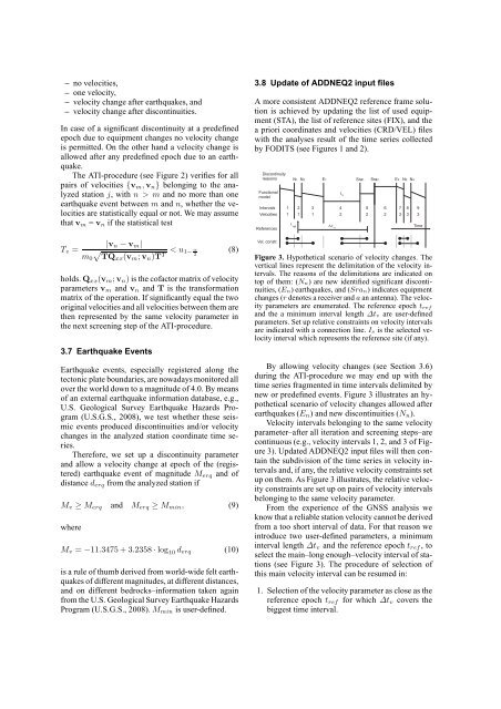
Figure 3. Hypothetical scenario of velocity changes. The<br />
vertical lines represent the delimitation of the velocity intervals.<br />
The reasons of the delimitations are indicated on<br />
top of them: (Nn) are new identified significant discontinuities,<br />
(En) earthquakes, and (Sran) indicates equipment<br />
changes (r denotes a receiver and a an antenna). The velocity<br />
parameters are enumerated. The reference epoch tref<br />
and the a minimum interval length ∆tv are user-defined<br />
parameters. Set up relative constraints on velocity intervals<br />
are indicated with a connection line. Is is the selected velocity<br />
interval which represents the reference site (if any).<br />
By allowing velocity changes (see Section 3.6)<br />
during the ATI-procedure we may end up with the<br />
time series fragmented in time intervals delimited by<br />
new or predefined events. Figure 3 illustrates an hypothetical<br />
scenario of velocity changes allowed after<br />
earthquakes (En) and new discontinuities (Nn).<br />
Velocity intervals belonging to the same velocity<br />
parameter–after all iteration and screening steps–are<br />
continuous (e.g., velocity intervals 1, 2, and 3 of Figure<br />
3). Updated ADDNEQ2 input files will then contain<br />
the subdivision of the time series in velocity intervals<br />
and, if any, the relative velocity constraints set<br />
up on them. As Figure 3 illustrates, the relative velocity<br />
constraints are set up on pairs of velocity intervals<br />
belonging to the same velocity parameter.<br />
From the experience of the GNSS analysis we<br />
know that a reliable station velocity cannot be derived<br />
from a too short interval of data. For that reason we<br />
introduce two user-defined parameters, a minimum<br />
interval length ∆tv and the reference epoch tref , to<br />
select the main–long enough–velocity interval of stations<br />
(see Figure 3). The procedure of selection of<br />
this main velocity interval can be resumed in:<br />
Time<br />
1. Selection of the velocity parameter as close as the<br />
reference epoch tref for which ∆tv covers the<br />
biggest time interval.