
Create successful ePaper yourself
Turn your PDF publications into a flip-book with our unique Google optimized e-Paper software.
2 | MSC Software<br />
MSC Software, the world leader<br />
in simulation technology presents<br />
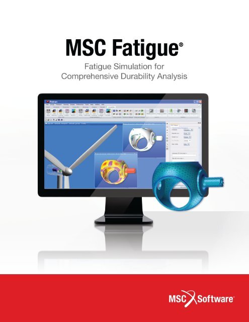
MSC <strong>Fatigue</strong> ®<br />
From aircrafts to cell phones, this state-of-the-art FE based <strong>Fatigue</strong> &<br />
Damage Tolerance solver for CAE enables the quick and accurate prediction<br />
of how long products will last under any combination of time-dependent or<br />
frequency-dependent loading conditions.<br />
The latest release of MSC <strong>Fatigue</strong> ® is now the most advanced, full featured<br />
durability product available in the marketplace. Its advanced fatigue life<br />
estimation program allows users to perform comprehensive fatigue analysis<br />
with the same FE results that are used for stress analysis. The environment<br />
seamlessly enables CAE, dynamic analysis and durability to be managed in<br />
one user friendly interface. It includes advanced modules developed by MSC<br />
Software over a 20 year period as well as more recent modules developed as<br />
part of the nCode DesignLife suite of programs.<br />
This brochure describes capabilities in the 2011 and 2012 versions of<br />
the product. Please keep an eye open for new composite fatigue, thermo<br />
mechanical fatigue and rubbers fatigue capabilities in the 2012.2 release.
An Integrated<br />
FE Based<br />
<strong>Fatigue</strong> Design<br />
Design Instead of Test<br />
New tools inside MSC <strong>Fatigue</strong> ® can simulate<br />
full body systems, offering the possibility<br />
for test cycle reductions and the associated<br />
cost savings.<br />
Get It Right the First Time<br />
<strong>Fatigue</strong> failures in the field result in<br />
costly retrofits. With MSC <strong>Fatigue</strong> ® , the<br />
effectiveness of proposed redesigns can be<br />
established in advance.<br />
Manage <strong>Fatigue</strong> & Durability Data<br />
The durability process includes laboratory<br />
and field testing and Mechanical Computer-<br />
Aided Engineering (MCAE) data handling in<br />
addition to fatigue analysis.<br />
MODELS + RESULTS<br />
Geometry & FEA<br />
(Stress/Strain) Results<br />
Loading and/or<br />
Test (Lab) Results<br />
Materials Information<br />
MSC <strong>Fatigue</strong> ® has the ability to store and<br />
seamlessly manage all aspects of the<br />
durability process.<br />
Understand <strong>Fatigue</strong> Behavior<br />
Reliability failures often result from an<br />
inadequate understanding of the fatigue<br />
process. MSC <strong>Fatigue</strong> ® is the most<br />
suitable and intuitive tool on the market to<br />
understand the key drivers that affect<br />
fatigue life.<br />
Auditable and Repeatable Processes<br />
MSC <strong>Fatigue</strong> is configured to run in a<br />
similar way to Nastran using an editable text<br />
batch file (cf BDF file). This leaves a useful<br />
auditable trail as well as a convenient means<br />
to run in batch mode.<br />
ANALYSIS OPTIONS<br />
• Stress (total) Life<br />
• Strain (initiiation) Life<br />
• Crack Propagation<br />
• Vibration <strong>Fatigue</strong><br />
• Multiaxial <strong>Fatigue</strong><br />
• Spot & Seam Weld<br />
• Wheels <strong>Fatigue</strong><br />
• Software Strain Gauge<br />
• Utilities<br />
POSSIBILITIES<br />
Incorporate More Reliable Material<br />
Properties<br />
Because reliable materials data is an<br />
essential part of any fatigue and durability<br />
process, MSC Software is pleased to now<br />
offer a comprehensive materials testing<br />
service (see separate brochure)<br />
Comprehensive Solution<br />
MSC Software now offers a complete<br />
solution including advanced fatigue software<br />
(MSC <strong>Fatigue</strong> ® ), advance materials testing<br />
facilities and, new with this release, a<br />
comprehensive engineering analysis (for<br />
fatigue) consulting service.<br />
<strong>Fatigue</strong> Life Contours<br />
Sensitivity Analysis<br />
+ Optimization<br />
Damage Distributions<br />
Tabular Results<br />
<strong>Fatigue</strong> Product <strong>Brochure</strong> | 3
4 | MSC Software<br />
Geometry & Mesh<br />
Patran<br />
Mode Shape Analysis<br />
MSC Nastran<br />
System-Level Simulation<br />
Adams<br />
<strong>Fatigue</strong> Life Calculation<br />
MSC <strong>Fatigue</strong><br />
Improve Productivity<br />
MSC <strong>Fatigue</strong> ® offers the best-integrated durability solver for the MCAE market. It is the only<br />
durability solver that seamlessly links to MSC Nastran , Adams and Patran . It is also the<br />
only solver that can directly read Marc’s ® non-linear results.<br />
Using MSC <strong>Fatigue</strong> ® early in the design process reduces the high cost of testing and<br />
prototyping to get your products to market faster with reliable warranties.<br />
MSC <strong>Fatigue</strong> ® is easy to learn and use. Resources include the Quick Start Guide, on-line help,<br />
MSC Software’s ® excellent technical support and extensive documentation.<br />
Capabilities<br />
• HCF, LCF & Crack Growth<br />
• FE Results support (Static, Transient,<br />
Modal, FRF, PSD)<br />
- MSC Nastran <br />
- Adams <br />
- Marc ®<br />
- ABAQUS<br />
- ANSYS<br />
• Advanced Analysis Modules (Multiaxial<br />
<strong>Fatigue</strong>), Vibration <strong>Fatigue</strong>, Shaker<br />
<strong>Fatigue</strong>, Welding (Spot & Seam),<br />
Software Strain Gauge, Wheels,<br />
Utilities, Fracture<br />
• Unique Optimization Capability<br />
- Load Scale Factor<br />
- Materials<br />
- Surface Finish/Treatments<br />
- Certainty of Survival<br />
• Test/Analysis Correlation<br />
• Duty Cycle (Multiple Analysis)<br />
- Aero-spectrum loading definition
MSC <strong>Fatigue</strong> Packages<br />
Life and Durability Analysis<br />
Base MSC <strong>Fatigue</strong><br />
Packages<br />
MSC <strong>Fatigue</strong> Basic<br />
Solver Package<br />
Includes Stress-Life, Strain-Life<br />
(401), and Strain Gauge (406)<br />
MSC <strong>Fatigue</strong> Complete<br />
Solver Package<br />
Includes Basic and Advanced<br />
Solver Packages<br />
(20033 + 20269)<br />
Optional MSC <strong>Fatigue</strong><br />
Advanced Modules<br />
MSC <strong>Fatigue</strong> Fracture MSC <strong>Fatigue</strong> Advanced<br />
Solver Package<br />
MSC <strong>Fatigue</strong> Vibration<br />
MSC <strong>Fatigue</strong> Multiaxial<br />
MSC <strong>Fatigue</strong> Wheels<br />
MSC <strong>Fatigue</strong> Welds<br />
Includes Spot Weld (408)<br />
and Seam Weld (10503)<br />
MSC <strong>Fatigue</strong> Utilities<br />
Optional Bundles Optional GUI Product<br />
Includes Fracture, Vibration,<br />
Muliaxial, Wheels, Welds<br />
and Utilities<br />
Patran for MSC <strong>Fatigue</strong><br />
Includes only the Patran<br />
license feature<br />
No CAD Import or FEA Solver<br />
Preferences Available<br />
<strong>Fatigue</strong> Product <strong>Brochure</strong> | 5
3 Major Principles of <strong>Fatigue</strong> Life Estimation<br />
MSC <strong>Fatigue</strong> ® incorporates the three major principles of <strong>Fatigue</strong><br />
Life Estimation: Stress-Life, Strain-Life and Crack Growth.<br />
6 | MSC Software<br />
“The results of the<br />
durability analysis<br />
showed good correlation<br />
with our physical test<br />
results on an initial<br />
prototype, giving us the<br />
confidence to predict<br />
service lives based on<br />
the virtual prototype<br />
simulation.<br />
As a result...we only<br />
need one physical<br />
prototype and are on<br />
track to completing the<br />
design in only one year.”<br />
Terry Ewanochko, Product Engineer<br />
John Deere Welland<br />
Stress-Life<br />
This is the traditional Stress Life, or S-N<br />
method, used for High Cycle <strong>Fatigue</strong><br />
applications (HCF - low load - long life) that<br />
makes no distinction between initiation or<br />
growing a crack, but rather, predicts the<br />
total life to failure.<br />
Strain-Life<br />
This method is generally used for high<br />
load-low life applications (Low Cycle<br />
<strong>Fatigue</strong> - LCF), where material yield due to<br />
the application of high loads is taken into<br />
account. Sophisticated Strain-Life (e-N)<br />
modeling provides a method for estimating<br />
the life of a part to a user-defined<br />
limit - generally the initiation of an<br />
engineering crack.<br />
Crack Growth<br />
Linear Elastic Fracture Mechanics (LEFM)<br />
is used to predict the progress of a crack<br />
through a component to the point where<br />
rapid fracture causes failure. The method<br />
is widely used in the Aerospace industry<br />
where demonstration of damage tolerance<br />
is a design criterion.
Advanced Application Modules<br />
MSC <strong>Fatigue</strong> ® predicts fatigue life from finite element (FE) models. MSC <strong>Fatigue</strong> ®<br />
is fully modularized, enabling customization to suit your needs, and includes:<br />
“We evaluated MSC<br />
<strong>Fatigue</strong> against several<br />
commercial competitive<br />
alternatives. The reason<br />
we chose MSC <strong>Fatigue</strong><br />
was becaause of its<br />
wide range of analysis<br />
capabilities and also<br />
because it has a strong<br />
pedigree.”<br />
MSC <strong>Fatigue</strong> ® Basic<br />
Stress-life, Strain-Life, multi-axial<br />
assessment, and safety factor analysis<br />
based on linear elastic FEA.<br />
MSC <strong>Fatigue</strong> ® Vibration<br />
Frequency based (vibration) and time<br />
domain (Modal Participation Factor)<br />
methods are available for single and<br />
multi input loading systems.<br />
MSC <strong>Fatigue</strong> ® Shaker<br />
Sine sweep and PSD analysis of single<br />
input loading systems.<br />
MSC <strong>Fatigue</strong> ® Seam Weld<br />
Stress-Life, Strain-Life and safety factor<br />
analysis based on linear elastic FEA.<br />
MSC <strong>Fatigue</strong> ® Spot Weld<br />
Stress-life, Strain-Life, multi-axial<br />
assessment, and safety factor analysis<br />
based on linear elastic FEA.<br />
MSC <strong>Fatigue</strong> ® Fracture<br />
Crack growth analysis based on linear<br />
elastic fracture mechanics including an<br />
interface to NASA/FLAGRO.<br />
MSC <strong>Fatigue</strong> ® Strain Gauge<br />
Virtual strain gauges pasted on an<br />
FE model for fatigue test/analysis<br />
correlation.<br />
MSC <strong>Fatigue</strong> ® Utilities<br />
A number of advanced fatigue utilities<br />
for load manipulation, graphical display,<br />
and single shot fatigue analysis.<br />
MSC <strong>Fatigue</strong> ® Wheels<br />
A tool for managing rotating FE system<br />
stress fields in order to compute<br />
fatigue life.<br />
MSC <strong>Fatigue</strong> ® Multiaxial<br />
Crack initiation and safety factor<br />
analysis of components with multiaxial<br />
stress states.<br />
MSC <strong>Fatigue</strong> ® Pre&Post<br />
Pre & Post processor for setting up,<br />
managing and displaying fatigue<br />
analysis for non Patran customers.<br />
(This module is not required for Patran <br />
customers.)<br />
<strong>Fatigue</strong> Product <strong>Brochure</strong> | 7
Post-Processing Functions<br />
Various listing and post-processing functions<br />
are also provided for investigating critical<br />
locations and producing tables, and 2D and<br />
3D plots. This includes the ability for rapid<br />
re-analysis of critical nodes or elements to<br />
investigate the effects of material or loading<br />
changes or fatigue parameters without<br />
re-solving the complete model.<br />
Stress and strain component time histories<br />
can be exported for correlation and further<br />
analysis. A ‘Fast Analysis’ option is provided<br />
to more quickly identify critical locations<br />
prior to a complete analysis. This option<br />
utilizes a peak-valley slicing method to<br />
shorten the loading time histories and<br />
creates a set of most damaged locations for<br />
subsequent analysis.<br />
MSC <strong>Fatigue</strong> ® can directly use modal,<br />
transient time history stress/strain data or<br />
use static load cases (up to 500 with scaling<br />
and offset features) in combination with<br />
loading functions and perform the required<br />
stress/strain superposition. Multiple events<br />
and usage profiles can be analyzed with<br />
relative ease with the Duty Cycle Analyzer.<br />
Multiple materials and surface finishes can<br />
be assigned to different parts of the model<br />
by defining groups.<br />
8 | MSC Software<br />
Modifiable Loads Database with standard<br />
time histories and capability for adding<br />
time histories from:- ASCII file import, XY<br />
point specification, Graphical Interaction,<br />
Waveform & Block definitions.<br />
Modifiable Materials Database that has an<br />
extensive library of S-N, E-N, Cyclic and<br />
Component curves with import capability<br />
from MSC Mvision.<br />
Material searches based on design life.<br />
Results & “What If” Analysis<br />
Results data is reported both in tabular form<br />
and in results files for graphical display in<br />
the results postprocessor. A single location<br />
analyzer can be used for “what if” studies<br />
after a global analysis has identified<br />
critical locations.<br />
Results data include:<br />
• Damage (reported in linear and log form)<br />
• Life (reported in linear and log form)<br />
• Life reported in user defined units<br />
• Multiaxial assessment parameters:<br />
• Factor of safety<br />
• Stress history output<br />
• Cycle and damage histogram plots<br />
Back calculations based on design life of:<br />
• Scale factor (stress concentration)<br />
• Residual stress<br />
• Probability of failure (design criterion)<br />
Sensitivity studies of:<br />
• Multiple scale factors (stress<br />
concentrations)<br />
• Multiple residual stress values<br />
• Multiple probabilities of failures (design<br />
criteria)<br />
• Surface finish/treatment<br />
• Mean stress correction methods<br />
• Change materials or surface finish/<br />
treatment
MSC <strong>Fatigue</strong> ® Basic<br />
New DTLIB solver in 2012<br />
MSC <strong>Fatigue</strong> ® uses stress or strain results from finite element (FE) models,<br />
variations in loading, and cycling material properties to estimate life-to-failure.<br />
Time History Rainflow Cycle Counting Damage Counting Damage Histogram <strong>Fatigue</strong> Life<br />
Both the traditional Stress-Life (S-N or total<br />
life) and Strain-Life (E-N, local strain or<br />
Crack Initiation) methods are available. With<br />
minimal knowledge of fatigue analysis, users<br />
can perform such evaluations directly in<br />
their familiar FE modeling environment. The<br />
intuitive interface and the speed at which<br />
the fatigue analysis is performed enables<br />
durability concerns to be moved up front in<br />
the product development cycle, thus avoiding<br />
costs due to re-designs, prototyping<br />
and testing.<br />
Features Pertaining to both the<br />
Stress-Life and Strain-Life methods<br />
• Rainflow cycle counting<br />
• Statistical confidence parameters<br />
• surface finish/treatment corrections<br />
• Palmgren-Miner linear damage summation<br />
including Flexible Miner’s sum (>0, default<br />
= 1.0)<br />
• User-defined life units<br />
• Multi-axial stress state assessments<br />
• Factor of safety analysis<br />
• Stress/Strain tensor combination/<br />
resolution - any individual component,<br />
Maximum absolute principal, Signed von<br />
Mises, Signed Tresca/Shear<br />
• Critical Plane Analysis<br />
• Scale Factors (stress concentration<br />
definitions)<br />
• Offsets - Static load cases<br />
• Results transformations - Global system<br />
and Surface Resolved<br />
• Up to 500 simultaneously applied<br />
load case<br />
Stress-Life features include:<br />
• Goodman, Gerber (tension only),<br />
Interpolation-type mean stress correction<br />
(Multi-Mean and Multi R-Ratio Curve,<br />
Haigh Diagram, Bastonaire)<br />
• Welded Structure Analysis to BS7608<br />
• Material and Component S-N Curves;<br />
Interpolation-type S-N curves<br />
• FKM mean stress correction (ver 2012)<br />
Strain-Life features include:<br />
• Neuber and Hoffmann Seeger<br />
elastic-plastic correction<br />
• Cyclic stress-strain tracking using<br />
Masing’s hypothesis and material memory<br />
modeling<br />
• Smith-Watson-Topper, Morrow, and<br />
Interpolation-type mean stress correction<br />
(Multi-Mean and Multi R-Ratio Curve)<br />
• Advanced biaxial corrections (for nonproportional<br />
loading) based on Parameter<br />
Modification of Hoffman-Seeger<br />
<strong>Fatigue</strong> Product <strong>Brochure</strong> | 9
MSC <strong>Fatigue</strong> ® Vibration<br />
MSC <strong>Fatigue</strong> ® Vibration predicts the fatigue life of structures subjected to multiple<br />
input random vibration loads.<br />
Dirlik solution Typical vibration acceleration specifications<br />
It is important for designers to estimate<br />
response at resonance for structures<br />
subjected to random input loads and this<br />
analysis is best performed in the frequency<br />
domain using (PSD’s) of input loading and<br />
stress response. The Vibration <strong>Fatigue</strong><br />
module can perform fatigue analysis using<br />
either direct external response PSD’s<br />
(where the stress solver is used to calculate<br />
the PSD’s) or PSD’s calculated within the<br />
Vibration module using, as input, the loading<br />
PSD’s and system transfer funcions. Transfer<br />
functions can be computed for various<br />
stress scalar values including<br />
Principal Stresses.<br />
The Vibration <strong>Fatigue</strong> Module<br />
The Vibraton <strong>Fatigue</strong> module uses the<br />
S-N method to predict life (there is also<br />
an indirect route using Strain-Life) and<br />
a single shot analyzer that accepts a<br />
measured or analytically determined<br />
stress response PSD.<br />
10 | MSC Software<br />
Specific Features include:<br />
• Welded structure analysis to BS7608<br />
• Goodman and Gerber Mean stress<br />
corrections<br />
• Probability Density Functions of Rainflow<br />
cycles (various matrix (bin) sizes<br />
(32,64,128)<br />
• Stress/Strain Tensor combination/<br />
resolution - Individual Components, Max<br />
abs Principal, Signed Von Mises, Signed<br />
Tresca/Shear<br />
• FE Results transformations<br />
• Computation of Principal Stress response<br />
PSDs at any locaton from transfer<br />
functions and input loading PSD’s<br />
• Palmgren-Miner linear damage<br />
summation including flexible Miner’s sum<br />
(>0, default=1.0)<br />
• Multiaxial Stress state assessments<br />
(stress tensor mobility & biaxiality checks)<br />
• Surface Finish/Treatment Corrections<br />
• Twenty FE load cases with associated<br />
input load PSDs can be applied<br />
Moments from a PSD<br />
simultaneously. A loading database is also<br />
supplied to facilitate creation and storage<br />
of these PSD’s<br />
• PSD creation from time series data,<br />
ASCII file import, graphical or XY point<br />
specification, wave form definitions (sine,<br />
triangular, square)<br />
• Data transformations<br />
• Plots of PSD’s and Rainflow data<br />
Multiple Analysis Methods<br />
• Dirlik<br />
• Narrow Band<br />
• Steinberg<br />
• Tunna<br />
• Wirsching<br />
• Hancock<br />
• Kam & Do<br />
Mode 1 Mode 2 Mode 3 Mode 4 Mode 5
MSC <strong>Fatigue</strong> ® Shaker<br />
New DTLIB solver in 2012<br />
MSC <strong>Fatigue</strong> ® Shaker predicts the fatigue life of components subjected to a single input<br />
random vibration load.<br />
“The MSC <strong>Fatigue</strong><br />
Vibration module<br />
enabled us to design<br />
our components more<br />
accurately (with less<br />
conservatism) than<br />
the traditional Narrow<br />
Band or Steinberg<br />
approaches”<br />
Shaker table tests are widely specified<br />
and are routinely used to “proof test”<br />
components before sign-off. Typical input<br />
loads could be displacement, velocity or<br />
accelerations PSD’s.<br />
<strong>Fatigue</strong> analysis is then performed in<br />
the frequency domain rather than the<br />
traditional time-based domain approach.<br />
Both the input loads characterization and<br />
the damage analysis are performed in the<br />
frequency domain using Power Spectral<br />
Densities (PSD’s).<br />
The Shaker <strong>Fatigue</strong> Module<br />
The Shaker <strong>Fatigue</strong> module can perform<br />
fatigue analysis using either direct external<br />
response PSD’s (where the stress solver<br />
is used to calculate the PSD’s) or PSD’s<br />
calculated within the Shaker module<br />
using the input loading PSDs and system<br />
transfer functions. Transfer functions can be<br />
computed for various stress scalar values<br />
including Principal stresses.<br />
Multiple Analysis Methods<br />
• Dirlik<br />
• Narrow Bank<br />
• Steinberg<br />
• Lalanne<br />
New Sine Sweep Capability<br />
• Multiaxial Stress state assessments<br />
(stress tensor mobility & biaxiality checks)<br />
• Surface Finish/Treatment Corrections<br />
Is the highest possible frequency of loading greater<br />
than one third of the 1 st natural frequency?<br />
• Twenty FE load cases with associated<br />
input load PSDs can be applied<br />
simultaneously. A loading database<br />
is also supplied to facilitate the<br />
management of these PSDs.<br />
• PSD creation from time series data,<br />
ASCII file import, graphical or XY point<br />
specification, wave form definitions (sine,<br />
triangular, square)<br />
• Data transformations<br />
• Rainflow cycle counting and Damage<br />
histograms, Stress PSD CSV output<br />
<strong>Fatigue</strong> Product <strong>Brochure</strong> | 11
MSC <strong>Fatigue</strong> ® Spot Weld<br />
New DTLIB solver in 2011<br />
MSC <strong>Fatigue</strong> ® Spot Weld is a module for predicting the fatigue life of spot-welded<br />
sheet connections using static or dynamic FE results from MSC Nastran <br />
or Adams with the S-N (total life) method.<br />
Analysis of spot welds using MSC <strong>Fatigue</strong> ®<br />
Spot Weld can help you produce optimized<br />
designs and reduce prototyping and<br />
testing costs.<br />
The MSC <strong>Fatigue</strong> ® Spot Weld Module<br />
Modern automotive structures can have<br />
4000-6000 spot welds & approximately 80%<br />
of automotive body durability problems<br />
are associated with spot welds. Tooling<br />
costs for spot welds are high & the need<br />
for rapid & accurate predictions of fatigue<br />
life on spot welds early in the design stage<br />
is very important. Besides the structural<br />
importance, durability of spot welds can also<br />
have an important effect of perceived quality<br />
of a part or component.<br />
MSC <strong>Fatigue</strong> ® Spot Weld supports results<br />
from 3 commonly used modeling methods &<br />
uses the Rupp, Storzel & Grubisic algorithm<br />
for computing stresses in each spot-weld<br />
nugget & in adjacent sheets.<br />
• Spot welds modeled as stiff beams. The<br />
method requires attention to align the<br />
spot weld nodes on each flange but is<br />
suitable for application to large models<br />
as local mesh refinement around the spot<br />
weld is not required.<br />
• MSC Nastran CWELD elements. The<br />
power & modeling flexibility afforded by<br />
CWELD element is utilized. The CWELD<br />
allows users to model spot welds<br />
between dissimilar flange meshes of<br />
any refinement. CWELD results are used<br />
directly by MSC <strong>Fatigue</strong> ® Spot Weld.<br />
• Spot welds modeled using CHEX/<br />
MPC. This method also allows users to<br />
model spot welds between dissimilar<br />
flange meshes. MSC <strong>Fatigue</strong> ® computes<br />
“equivalent” bar forces automatically and<br />
posts fatigue results on the faces of the<br />
CHEX elements.<br />
12 | MSC Software<br />
• Automatic extraction of Spot Weld<br />
Analysis Groups<br />
- By flange thickness pairs<br />
- Weld diameter extracted<br />
automatically<br />
• 150 analysis groups<br />
• No limit on spot welds per group<br />
• 500 load channels<br />
Capabilities of the Spot Weld<br />
Analyzer<br />
• Analysis of welds joining two metal sheets<br />
• Three sheet correction (ver. 2011)<br />
• Weld nugget & sheet fatigue life –<br />
user configurable number of fatigue<br />
calculations performed per spot weld.<br />
• Rainflow cycle counting - various matrix<br />
(bin) sizes (32, 64, 128)<br />
• Statistical Confidence parameters<br />
• Palmgren-Miner linear damage summation<br />
• Flexible Miner’s sum (>0, default=1.0)<br />
• Spot weld S-N curves - Includes Generic<br />
Spot Weld (S-N curves for nugget & sheet)<br />
• Add, create or modify materials data<br />
• Graphical & tabular reports of Life &<br />
Damage in linear & log form<br />
• User Defined Units for Life reporting<br />
• Polar plots of life/damage for nugget &<br />
sheets (ver. 2012)<br />
• Polar plots of stress for nugget & sheets<br />
(ver. 2012)<br />
• Stress Time history output (ver. 2012)<br />
• Damage & cycle histogram plots (ver.<br />
2012)<br />
• Failure location – nugget, top or bottom<br />
sheet
MSC <strong>Fatigue</strong> ® Seam Weld<br />
New DTLIB solver in 2011<br />
MSC <strong>Fatigue</strong> ® includes, as standard, the traditional weld classification approach (BS5400/<br />
BS7608 etc.) for the fatigue design of weldment details as well as the more modern<br />
structural stress approach.<br />
“Where a welded<br />
configuration used<br />
to take one week to<br />
analyze it, now takes<br />
just four hours.“<br />
The Weld Classification Approach<br />
Using this type of approach there is no<br />
requirement to model the weld detail.<br />
Instead, “component” S-N curves are used<br />
which have the weld classification detail<br />
(loading and geometry) built into the S-N<br />
detail. This approach can, however, be<br />
awkward and time consuming to implement<br />
for thin sheet styles commonly used for<br />
automotive manufacturing because the level<br />
of integration with FE is minimal.<br />
More recent work has focused on<br />
calculating the equivalent structural stress<br />
in the weld detail. The method implemented<br />
in MSC <strong>Fatigue</strong> ® is based on the method<br />
developed by Fermer et al. Ref: SAE 982311<br />
Filet Overlap<br />
Available Weld Configurations<br />
• Weld root and weld throat failure<br />
prediction available<br />
• Additional weld types for brazing and<br />
lazer welds<br />
• Interpolation between bending and<br />
tension S-N curves rather than just using<br />
one or the other<br />
• Users can define the bending ratio<br />
threshold to effect the start of the<br />
interpolation<br />
• Faster solver also capable of multithreading<br />
(parallel processing)<br />
• Native 64 bit solver (on 64 bit machines)<br />
• New DTMAT material interface is enabled<br />
• Seam weld solver will also benefit from<br />
expanded duty-cycle capability (complete<br />
overhaul of the existing duty cycle<br />
method in 2012)<br />
<strong>Fatigue</strong> Product <strong>Brochure</strong> | 13
MSC <strong>Fatigue</strong> ® Fracture<br />
Crack Growth Analysis<br />
MSC <strong>Fatigue</strong> ® Fracture uses stress results from finite element (FE) models, variations<br />
in loading & cyclic material properties to estimate crack propagation rates & times.<br />
Traditional linear elastic fracture mechanics (LEFM) are used to determine<br />
crack growth.<br />
Crack Growth Modeling<br />
MSC <strong>Fatigue</strong> ® Fracture provides<br />
sophisticated crack growth modeling for<br />
estimating life to grow a crack through a<br />
structure. Features include:<br />
• Kitagawa minimum crack sizing<br />
• Fracture toughness failure criterion<br />
• Mean stress correction<br />
• Rain flow cycle counting with<br />
cycle re-ordering<br />
• Initial and final crack length specifications<br />
• Plane stress correction<br />
• Notch effects modeling<br />
• Retardation and closure effects modeling<br />
• Modified Paris law modeling based on<br />
effective stress intensity range<br />
• User-defined life units<br />
• Fracture mechanics triangle solutions<br />
(stress – stress intensity – crack length)<br />
• Graphical interface to NASA/FLAGRO<br />
2.03 (via Patran or MSC <strong>Fatigue</strong> ® Pre &<br />
Post)<br />
• Stress tensor combination/resolution<br />
Models and results can be imported in a<br />
variety of ways: Patran neutral and external<br />
(nod, ele, els) results file MSC Nastran OP2<br />
and XDB file Marc ® , ABAQUS, ANSYS and<br />
SDRC results files<br />
14 | MSC Software<br />
Fracture analysis is performed using stress<br />
results from FE models that define the<br />
nominal or far field stress, which can be<br />
defined as a single location or averaged<br />
from an area on the model. Manual input<br />
is also possible with no reliance on an FE<br />
model. Results access features include FE<br />
results data from:<br />
• Patran database (linear static and<br />
transient results)<br />
• MSC Nastran , ANSYS, ABAQUS, Marc ® ,<br />
and any other Patran supported analysis<br />
code<br />
Multiple FE load cases with associated<br />
time variations can be defined and applied<br />
simultaneously. A time history database is<br />
supplied to facilitate creation and storage of<br />
these files.<br />
A materials database manager stores and<br />
manipulates a library of cyclic material<br />
properties. Features include:<br />
• Approximately 200 materials (metals)<br />
supplied<br />
• Add, create, or modify your own or<br />
supplied materials data (Imperial & SI<br />
units supported)<br />
Graphical display of:<br />
• Apparent stress intensity (DK)<br />
• Effective stress intensity (DK)<br />
• Threshold ratio DK plots<br />
Possible Results<br />
• Interactive XY plot of crack growth during<br />
the analysis<br />
• Final crack length versus life curve<br />
• Final crack growth rate curve<br />
• Life interpolation due to different initial<br />
and final crack sizes<br />
• Stress history output<br />
• Tabular listing of life:<br />
- crack size,<br />
- growth rate<br />
- stress range<br />
- Apparent DK<br />
- Effective DK<br />
- Current overload K<br />
- Residual K<br />
- K at crack closure<br />
- K from static fracture<br />
- Effective stress ratio<br />
• Sensitivity studies of:<br />
- Multiple initial crack sizes<br />
- Multiple final crack sizes<br />
- Cyclic material parameters<br />
- Mean stress<br />
- Crack type<br />
- Environment
Compliance Function Library<br />
Various crack geometries are supported for<br />
determining the K-solution which include:<br />
• Standard specimens<br />
- Single edge crack in tension<br />
- Single edge crack in pure bending<br />
- Double edge crack in tension<br />
- Center cracked plate in tension<br />
- Center cracked square plate<br />
in tension<br />
- Three-point bend specimen<br />
- Compact tension specimen<br />
- Round compact tension specimen<br />
- Wedge opening load specimen<br />
- Quarter circular corner crack<br />
tension specimen<br />
• Cracks at holes<br />
- Single crack at a hole in tension<br />
- Double crack at a hole in tension<br />
- Surface crack at a hole in tension<br />
• Elliptical, semi-elliptical cracks in plates<br />
- Surface cracks in tension<br />
- Surface cracks in bending<br />
- Embedded cracks in tension<br />
- Embedded cracks in bending<br />
- Surface and embedded cracks in<br />
combined loading<br />
• Cracks at corners<br />
- Quarter elliptical corner crack in<br />
tension<br />
- Quarter elliptical corner crack at a<br />
hole in tension<br />
- Cracks in solid cylinders<br />
- Circumferential crack in tension<br />
- Straight crack in tension<br />
- Semi-circular crack in tension<br />
- Crack at thread in tension<br />
- Straight crack in bending<br />
- Semi-circular crack in bending<br />
• Cracks in hollow cylinders<br />
- Internal surface crack under a<br />
hoop stress<br />
- Circumferential crack in thin-walled<br />
tube in tension<br />
• Cracks in welded plate joints<br />
- Weld toe surface cracks in tension<br />
- Weld toe surface cracks in bending<br />
- Weld toe embedded cracks in<br />
tensionWeld toe embedded cracks<br />
in bending<br />
- Surface cracks in combined tension<br />
and bending<br />
• Cracks in welded tubular joints<br />
• Cracks at spot welds in tension<br />
• User parametric definitions<br />
<strong>Fatigue</strong> Product <strong>Brochure</strong> | 15
MSC <strong>Fatigue</strong> ® Strain-Gauge<br />
Virtual Strain Gauges<br />
MSC <strong>Fatigue</strong> ® Strain Gauge allows the creation of virtual Software Strain Gauges<br />
within an MSC Nastran finite element (FE) model. These gauges can be used<br />
to produce analytical response time histories from the FE model under the effect<br />
of multiple time varying applying loads.<br />
Strain Gauge Definitions<br />
The Software Strain Gauges are defined<br />
as FE groups, each containing from one to<br />
three elements. All standard strain gauge<br />
definitions are supported in both planar and<br />
stacked formulations. User defined gauges<br />
may also be created, with definitions stored<br />
in a gauge definition file.<br />
The virtual strain gauges are positioned<br />
on the FE model surface, with the gauge<br />
aligned in any orientation and the gauge<br />
positioned independently of existing<br />
finite elements. The results obtained from<br />
the Software Strain Gauge are averaged<br />
results from the underlying finite elements,<br />
modeling the same geometric averaging<br />
obtained with actual instrumentation from a<br />
physical prototype. Results are transformed<br />
to the coordinate system, and alignment of<br />
the software strain gauge and results must<br />
be surface resolved.<br />
16 | MSC Software<br />
The MSC <strong>Fatigue</strong> ® Strain Gauge<br />
Stress and strain time histories may be<br />
extracted at any point on the FE model<br />
surface, based on either standard or<br />
user-defined strain gauge definitions. The<br />
results obtained from the Software Strain<br />
Gauge may be based on static, transient, or<br />
quasi-static FE loading.<br />
Use of the MSC <strong>Fatigue</strong> ® Strain Gauge<br />
allows the FE analyst to correlate<br />
theoretical structural integrity calculations<br />
with experimentally determined results.<br />
This tool permits the engineering analyst<br />
greater confidence in the FE model of<br />
the real-world structure. Analysis using<br />
MSC <strong>Fatigue</strong> ® significantly reduces costs<br />
associated with prototyping and testing by<br />
simulating fatigue life early in the design<br />
phase, thus shortening time-to-market<br />
and improving product reliability, customer<br />
confidence, and reducing costly recalls<br />
or other undesirable consequences of<br />
premature product failure. Usage of MSC<br />
<strong>Fatigue</strong> ® brings fatigue analysis up front<br />
in the design-to-manufacturing process<br />
and creates an MCAE environment for<br />
integrated durability management.<br />
Capabilities of the Software<br />
Strain Gauge<br />
The Software Strain Gauge can extract FE<br />
results and combine them with loading time<br />
variations to create response time history<br />
for the following strain gauges,<br />
• Uniaxial Gauges<br />
• T Gauges<br />
• Delta and Rectangular Gauges<br />
• Stacked and Planar Gauges<br />
• User Specified Gauge Definitions<br />
• Up to 200 simultaneous Software Strain<br />
Gauges<br />
Software Strain Gauges<br />
The full range of Stress-Life, Strain-Life<br />
and Critical Plane analysis methods can be<br />
applied to calculated Strain Gauge results.<br />
The Software Strain Gauge is also of benefit<br />
to the analyst performing MSC <strong>Fatigue</strong> ®<br />
weld durability calculations in accordance<br />
with British Standard 7608. The Gauge tool<br />
allows ready access to strain time histories<br />
at the weld toe, providing important<br />
information for weld durability calculations.
MSC <strong>Fatigue</strong> ® Wheels<br />
MSC <strong>Fatigue</strong> ® Wheels provides a fatigue analysis tool to predict<br />
the long-term effects of such cyclic loading.<br />
Predicting Wheel Life<br />
Aircraft wheels play a major role in the<br />
takeoffs and landings of an aircraft, whether<br />
its a 747 loaded with 568 passengers,<br />
the Space Shuttle, or an F-16 Fighting<br />
Falcon. Repetitive landings, takeoffs and<br />
associated taxi runs subjects the wheels to a<br />
considerable spectrum of operational loads<br />
that the wheels must withstand time and<br />
again. Ensuring that a wheel meets stress<br />
and load criteria over time is an important<br />
part of the product development process<br />
and typically is accomplished by testing<br />
physical prototypes. However building<br />
and testing a prototype is expensive and<br />
time consuming and wheel development<br />
programs often require several prototypes<br />
be evaluated before the production design<br />
is finalized.<br />
<strong>Fatigue</strong> Damage Contour Plot<br />
MSC <strong>Fatigue</strong> ® Wheels provides a fatigue<br />
analysis tool to predict the long-term effects<br />
of such cyclic loading. Predicting wheel life<br />
for a spectrum of load conditions through<br />
simulation using MSC <strong>Fatigue</strong> ® involves<br />
determining stress-time histories at nodes<br />
in the model for each load condition and<br />
determining the critical plane for each node<br />
on which the stress-time histories produce<br />
the greatest amount of fatigue damage for<br />
all load conditions in the spectrum.<br />
MSC <strong>Fatigue</strong> ® Wheels extracts the stress-<br />
time histories at each node from the defined<br />
FEA solution sets for each load condition,<br />
with stress-time histories developed for<br />
each user-defined angular increment about<br />
each node for every load condition. Mean<br />
stress, stress range, and subsequent<br />
fatigue damage for each angular increment<br />
is calculated. The plane of critical fatigue<br />
damage is calculated by summing the<br />
fatigue damages obtained for each<br />
angular increment.<br />
Aircraft wheels are designed to meet the<br />
fatigue life requirements specified by<br />
an aircraft manufacturer (OEM). <strong>Fatigue</strong><br />
life requirements consist of a spectrum<br />
of ground load conditions containing<br />
combinations of vertical and lateral loads.<br />
Each load condition is applied to the wheel<br />
for a portion of the required life of the wheel,<br />
which is specified in distance<br />
(miles or kilometers).<br />
The ground load conditions are specified<br />
at the tire to ground interface and actually<br />
apply loads to the tire as shown above. The<br />
tire in turn imparts a distributed contact<br />
pressure on the wheel rim. Since the tire<br />
is not included as part of the wheel FEA<br />
model, the tire loading of the wheel rim must<br />
be determined. The tire contact pressures<br />
must be obtained from either experimental<br />
measures or from the tire FEA analysis<br />
performed by tire manufacturer.<br />
A full FEA transient analysis to obtain the<br />
wheel stress fluctuations for each load<br />
condition is not feasible. The alternate, but<br />
reasonably accurate approach is to perform<br />
several linear static FEA for each loading<br />
condition. Each incremental static FEA for<br />
particular loading condition represents an<br />
incremental rotation of the wheel, so all of<br />
them together represents the state of<br />
stress/strain at any point on the wheel<br />
versus time (in terms of wheel<br />
rotation angle).<br />
Wheel Rotation<br />
The wheel rotation is represented by rotation<br />
of the loads and boundary conditions<br />
acting on the wheel. Once the stress/strain<br />
“histories” are obtained by performing<br />
several linear static FEA for each loading<br />
condition, fatigue damage and life are<br />
calculated for each loading condition,<br />
and the total fatigue damage can be<br />
approximated as the sum of damages from<br />
all loading conditions.<br />
The total fatigue damage, for each node/<br />
element of the wheel model, can be<br />
graphically represented as a damage<br />
contour plot in the usual way, visually<br />
showing the user where the fatigue-critical<br />
areas are located. the areas with maximum<br />
damage can be further analyzed as required.<br />
<strong>Fatigue</strong> Product <strong>Brochure</strong> | 17
MSC <strong>Fatigue</strong> ® Multiaxial<br />
MSC <strong>Fatigue</strong> ® Multiaxial uses stress or strain results from finite element (FE) models,<br />
variations in loading, and cyclic material properties to estimate life to failure.<br />
A non-proportional, multiaxial stress state is<br />
assumed as opposed to the usual uniaxial or<br />
proportional loading states.<br />
The Strain-Life and Stress-Life methods are<br />
used in the life prediction and safety factor<br />
analyses respectively.<br />
Safety Factor Analysis<br />
Safety factor analysis can be performed over<br />
the entire FE model or on a portion thereof.<br />
Analysis methods for multiaxial stress<br />
states include the Dang Van and McDiarmid<br />
methods.<br />
Sophisticated strain-life (crack initiation - e-N)<br />
modeling provides a method for estimating<br />
life to the “initiation” of an engineering crack<br />
from a multiaxial stress state. Six (6) local<br />
strain critical plane methods are available.<br />
Features include:<br />
• Normal Strain<br />
• Shear Strain<br />
18 | MSC Software<br />
• SWT-Bannantine<br />
• Fatemi-Socie<br />
• Wang-Brown - with and without mean<br />
stress correction<br />
• Or all methods at once<br />
Methods of Calculation<br />
These methods include the multiaxial<br />
non-proportional notch correction procedure,<br />
incorporating an energy-based notch rule<br />
based on Neuber’s rule and a Mroz-Garud<br />
cyclic plasticity model.<br />
A single shot multiaxial analyzer accepts<br />
elastic-plastic rosette stress or strain time<br />
histories directly. This input data can be from<br />
FE derived histories or measured data.<br />
Polar Plot of Critical Plane Analysis<br />
Methods of calculation include:<br />
• Normal Strain<br />
• Shear Strain<br />
• SWT-Bannantine<br />
• Fatemi-Socie<br />
• Wang-Brown - with and without mean<br />
stress correction<br />
• Or all methods at once<br />
<strong>Fatigue</strong> analysis is performed using stress or<br />
strain results from FE models. Results access<br />
features include linear static and transient<br />
(stresses) FE results data from all<br />
Patran supported databases:<br />
No limit on number of node or element<br />
calculation points<br />
Multiple FE load cases with associated<br />
time variations can be defined and applied<br />
simultaneously. A time history database is<br />
supplied to facilitate creation and storage of<br />
these files.<br />
A materials database manager stores and<br />
manipulates a library of cyclic<br />
material properties.
MSC <strong>Fatigue</strong> ® Pre&Post<br />
MSC <strong>Fatigue</strong> ® Pre&Post provides the required graphical interface to efficiently<br />
and easily set up, run and post process an MSC <strong>Fatigue</strong> ® analysis.<br />
MSC <strong>Fatigue</strong> ® Pre&Post uses stress or strain<br />
results from finite element (FE) models,<br />
variations in loading, and cyclic material<br />
properties to estimate life to failure of<br />
structures and components.<br />
Features & Functions<br />
MSC <strong>Fatigue</strong> ® Pre&Post gives direct and<br />
easy access to all features and functions of<br />
the MSC <strong>Fatigue</strong> ® product line including,<br />
• Stress-Life <strong>Fatigue</strong><br />
• Strain-Life <strong>Fatigue</strong><br />
• Crack Propagation<br />
• Multi Input Vibration <strong>Fatigue</strong><br />
• Single Input Shaker Table <strong>Fatigue</strong><br />
• Seam Weld <strong>Fatigue</strong><br />
• Spot Weld <strong>Fatigue</strong><br />
• Multi Axial <strong>Fatigue</strong><br />
• Wheels <strong>Fatigue</strong><br />
• <strong>Fatigue</strong> Utilities<br />
The Pre&Post Environment<br />
The Pre&Post environment is intended<br />
for the user who doesn’t need the full<br />
processing power of Patran to run MSC<br />
<strong>Fatigue</strong> ® or perhaps has an alternative pre<br />
& post for routine day to day pre & post<br />
processing work. The Pre&Post environment<br />
can easily be modifed to determine<br />
sensitivities and optimize designs for<br />
durability.<br />
MSC <strong>Fatigue</strong> ® Pre&Post gives access to<br />
FE information. Models and results can<br />
be imported in a variety of ways: Results<br />
access features include linear static and<br />
transient (stresses and strains) FE results<br />
data from all Patran supported databases:<br />
General capabilities exist for easy viewing<br />
and manipulation of the model:<br />
• Groups - break the model up into various<br />
sections for application of different<br />
material and surface finish/treatment<br />
combinations<br />
• Model manipulation - rotate, pan and<br />
zoom<br />
• Multiple graphic viewports<br />
• Various rendering styles (wireframe,<br />
hidden line, shaded) and display<br />
properties<br />
• General utilities for coordinate frame<br />
creation, node and element attributes<br />
• Associate time or frequency varying loads<br />
to FE load cases<br />
• Easily set up fatigue analysis parameters<br />
<strong>Fatigue</strong> Product <strong>Brochure</strong> | 19
MSC <strong>Fatigue</strong> ® Utilities<br />
MSC <strong>Fatigue</strong> ® Utilities contains advanced and practical applications to help the MSC <strong>Fatigue</strong> ®<br />
user who has a need to collect, analyze and post process measured data, such as stress or<br />
strain time histories, or to process such data to prepare for a subsequent MSC <strong>Fatigue</strong> ® analysis.<br />
Advanced Loading Manipulation<br />
Arithmetic Manipulation (MART) is a module which<br />
arithmetically manipulates standard loading<br />
data files.<br />
Multi-Channel Editor (MCOE) is an interactive<br />
alphanumeric editor that allows both the creation of<br />
new and the editing of existing time series<br />
data files.<br />
Rainflow Cycle Counter (MCYC) is used to process<br />
a time series signal by extracting fatigue cycles<br />
according to the Rainflow cycle counting algorithm.<br />
Formula Processor (MFRM) is an arithmetic and<br />
logical module which can be used to process<br />
formulae of varying complexity.<br />
File Cut and Paste (MLEN) is used to extract a<br />
portion of data from one file or several files, and<br />
load the extracted portions into a new output file.<br />
Multi-File Manipulation (MMFM) is an arithmetic<br />
and logical module which can be used to process<br />
formulae of varying complexity.<br />
Peak-Valley Extraction (MPVXMUL) extracts turning<br />
points from single parameter files such as dac and<br />
RPC multiple data - channel files.<br />
Simultaneous Values Analysis DAC/RPC<br />
(MSIMMAX) performs simultaneous values analysis<br />
on either multi channels in a single RPC file or<br />
multiple DAC files from the same test.<br />
Amplitude Distribution (MADA) calculates the<br />
probability density distribution and other function of<br />
a time signal.<br />
Auto Spectral Density (MASD) performs a frequency<br />
analysis of a time signal to determine<br />
frequency content.<br />
Fast Fourier Filter (MFFF) creates a finite impulse<br />
response (FIR), filter by using the window method.<br />
Butterworth Filtration (MBFL) takes a signal file and<br />
passes it through a Butterworth filter to produce an<br />
output signal file.<br />
20 | MSC Software<br />
+<br />
System Simulation Modal Coordinates + Stress Shapes<br />
Frequency Response Analysis (MFRA) analyses the<br />
response of a single input, single output<br />
linear system.<br />
Statistical Analysis (MRSTAT) analyses a time<br />
signal and produces a number of statistics about<br />
that signal.<br />
Header/Footer Manipulation (MFILMNP) allows both<br />
header and extra details manipulation.<br />
Advanced <strong>Fatigue</strong> Utilities<br />
Single Location S-N Analysis (MSLF) estimates<br />
fatigue life using test results using the<br />
Stress-Life approach.<br />
Single Location Strain-Life Analysis (MCLF) is the<br />
equivalent of MSC <strong>Fatigue</strong>’s Strain-Life module,<br />
FEFAT, but in the testing world where the input is a<br />
measured strain history from a single location.<br />
Cycle and Damage Analysis (MCDA) calculates and<br />
displays cycles and damage distributions so that<br />
different test conditions may be compared and the<br />
reasons for variations in fatigue damage may<br />
be determined.<br />
Time Correlated Damage (MTCD) is a fatigue<br />
analyzer that can be used to pin-point fatigue<br />
damage within a loading history.<br />
Single Location Vibration <strong>Fatigue</strong> (MFLF) is a single<br />
location, stress-based fatigue analysis module that<br />
accepts stress response PSDs as input.<br />
Multi-Axial Life Analysis (MMLF) is a single location<br />
multiaxial fatigue analyzer based on the<br />
Strain-Life approach.<br />
Crack Growth Data Analysis (MFCG) calculates the<br />
Paris Law coefficient and exponent from actual<br />
raw test data obtained under constant amplitude<br />
loading conditions.<br />
Kt/Kf Evaluation (MKTAN) stores and retrieves<br />
values for stress concentration factor (Kt) solutions<br />
for geometric details, and calculates Kt and Kf.<br />
=<br />
Stress in Component<br />
Graphical Display & Conversion Utilities<br />
Graphical Editing (MGED) is the multi-channel<br />
interactive graphical editor for time series data<br />
allowing online manipulation of a signal.<br />
Multi-File Display (MMFD) displays single parameter<br />
data files.<br />
Quick Look Display (MQLD) displays single channel<br />
data files.<br />
Two Parameter Display (MTPD) and Polar Display<br />
(MPOD) display pared (X-Y) data files.<br />
Three Dimensional Display (MP3D) is the histogram<br />
and waterfall display module.<br />
Binary/ASCII Convertor (MDTA/MATD) converts a<br />
single parameter, X-Y, or histogram binary file into<br />
ASCII format.<br />
Signal Regeneration (MREGEN) can regenerate a<br />
single parameter signal files from a three parameter<br />
range-mean cycles histogram file (cyg type), a three<br />
parameter maximum-minimum cycles histogram file<br />
(cyh type), a three parameter Markov Matrix (mkh<br />
type), and generate a Gaussian series from a user<br />
supplied irregularity factor and save it as a dac file.<br />
RPC to DAC - DAC to RPC - (MREMDAC/<br />
MDACREM) extracts channels of data from MTS<br />
RPC remote parameter (RPC) files, and creates a<br />
single dac file for each channel of the RPC file.<br />
Cross-Platform Conversion (MCONFIL) is a binary<br />
to binary file conversion program for transfer of files<br />
across multiple platforms.<br />
Waterfall File Create (MWFLCRE) creates a three<br />
parameter waterfall file from multiple single<br />
parameter files.
MSC <strong>Fatigue</strong><br />
®<br />
Predict <strong>Fatigue</strong> Life from Finite Element (FE) Models<br />
Fully Modularized and Customized to Suit Your Needs<br />
MSC Software is one of the ten original software companies and the worldwide leader<br />
in multidiscipline simulation. As a trusted partner, MSC Software helps companies improve<br />
quality, save time and reduce costs associated with design and test of manufactured<br />
products. Academic institutions, researchers, and students employ MSC technology<br />
to expand individual knowledge as well as expand the horizon of simulation.<br />
MSC Software employs professionals in 20 countries.<br />
For additional information about MSC Software’s products and services,<br />
please visit: www.mscsoftware.com<br />
Corporate<br />
MSC Software Corporation<br />
2 MacArthur Place<br />
Santa Ana, California 92707<br />
Telephone 714.540.8900<br />
www.mscsoftware.com<br />
Europe, Middle East,<br />
Africa<br />
MSC Software GmbH<br />
Am Moosfeld 13<br />
81829 Munich, Germany<br />
Telephone 49.89.431.98.70<br />
Asia-Pacific<br />
MSC Software Japan LTD.<br />
Shinjuku First West 8F<br />
23-7 Nishi Shinjuku<br />
1-Chome, Shinjuku-Ku<br />
Tokyo, Japan 160-0023<br />
Telephone 81.3.6911.1200<br />
Asia-Pacific<br />
MSC Software (S) Pte. Ltd.<br />
100 Beach Road<br />
#16-05 Shaw Tower<br />
Singapore 189702<br />
Telephone 65.6272.0082<br />
The MSC Software corporate logo, MSC, and the names of the<br />
MSC Software products and services referenced herein are trademarks<br />
or registered trademarks of the MSC Software Corporation in the United<br />
States and/or other countries. All other trademarks belong to their<br />
respective owners. © 2011 MSC Software Corporation. All rights reserved.<br />
MSCFATIGUE*2012JAN*BR