ROHR2 31.0 Feature list
ROHR2 31.0 Feature list
ROHR2 31.0 Feature list

You also want an ePaper? Increase the reach of your titles
YUMPU automatically turns print PDFs into web optimized ePapers that Google loves.
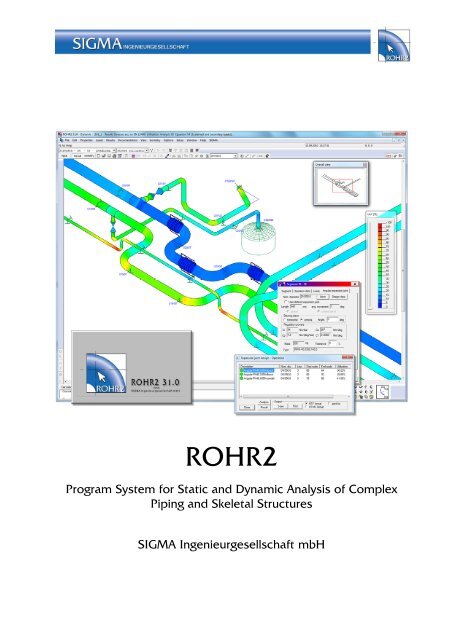
<strong>ROHR2</strong><br />
Program System for Static and Dynamic Analysis of Complex<br />
Piping and Skeletal Structures<br />
SIGMA Ingenieurgesellschaft mbH
<strong>ROHR2</strong> <strong>Feature</strong> <strong>list</strong><br />
Content<br />
Software<br />
Development,<br />
Sales and<br />
Support<br />
1 <strong>ROHR2</strong> Program description ........................................................... 2<br />
1.1 Program versions and Scope of delivery .......................................... 3<br />
1.2 Stress codes included in <strong>ROHR2</strong> ..................................................... 3<br />
1.3 Graphical User Interface <strong>ROHR2</strong>WIN .............................................. 4<br />
1.4 Documentation ............................................................................... 10<br />
1.5 Integrated Interfaces ...................................................................... 12<br />
1.6 Licensing ........................................................................................ 13<br />
1.7 Scope of supply and copy protection ............................................. 13<br />
1.8 System requirements ..................................................................... 13<br />
2 <strong>ROHR2</strong> Optional available programs ............................................ 14<br />
2.1 <strong>ROHR2</strong>iso ...................................................................................... 14<br />
2.2 <strong>ROHR2</strong>fesu .................................................................................... 15<br />
2.3 <strong>ROHR2</strong>stoss .................................................................................. 16<br />
2.4 Optional Interfaces - Integration of <strong>ROHR2</strong> ................................... 17<br />
3 Software Services .......................................................................... 18<br />
3.1 Program maintenance and updates, User support ......................... 18<br />
3.2 <strong>ROHR2</strong> Training............................................................................. 19<br />
4 <strong>ROHR2</strong> - Detailed features ............................................................ 20<br />
4.1 Overview ........................................................................................ 20<br />
4.2 Input features ................................................................................. 21<br />
4.3 Documentation ............................................................................... 22<br />
4.4 <strong>ROHR2</strong> Calculation program ......................................................... 23<br />
4.5 Stress codes in <strong>ROHR2</strong> Static and Dynamic ................................. 25<br />
SIGMA Ingenieurgesellschaft mbH<br />
Bertha-von-Suttner-Allee 19<br />
D-59423 Unna<br />
Germany<br />
Telephone: ++49 (0)2303 332 33-0<br />
Fax: ++49 (0)2303 332 33-50<br />
Email: info@rohr2.de<br />
Internet: www.rohr2.de<br />
www.rohr2.com<br />
Release 06.2011<br />
<strong>ROHR2</strong>_<strong>Feature</strong><strong>list</strong><br />
SIGMA Ingenieurgesellschaft mbH www.rohr2.com
<strong>ROHR2</strong> <strong>Feature</strong> <strong>list</strong><br />
Page 1<br />
ROHR means PIPE<br />
Expertise in pipe analysis is expressed in the product name: the German word ROHR means PIPE.<br />
<strong>ROHR2</strong> is the standard tool for pipe static and structural framework analysis, covering a variety of specifications like<br />
ASME, ANSI, EN 13480, STOOMWEZEN D1101 and BS 7159 or ISO 14692.<br />
The software environment can be supplemented by a range of programs enhancing the engineer’s daily job, as there<br />
are FE- analysis, isometric capabilities and interfaces covering the leading CAD/CAE systems.<br />
<strong>ROHR2</strong> was used by generations of engineers doing their jobs in power plants, nuclear power engineering, chemical<br />
industry, gas piping and technical control authorities.<br />
Pipe<br />
<strong>ROHR2</strong> means Stress<br />
Analysis<br />
<strong>ROHR2</strong> is made by engineers<br />
Started and created by one of the main software vendors in Europe - mbp in Germany - in the late 1960s, <strong>ROHR2</strong><br />
continues its success by SIGMA from 1989, also accompanied by EDS Software in the 90´s.<br />
From the year 2000 on, the complete licensing and sales activities are in the hands of SIGMA.<br />
SIGMA is an engineering company basing on pipe engineering as well as software development.<br />
The result is a field tested product, strongly adapted to the user’s needs.<br />
<strong>ROHR2</strong> means system integration<br />
<strong>ROHR2</strong> offers a large number of interfaces for the transfer of data from and to CAD and CAE-systems.<br />
Additionally <strong>ROHR2</strong>WIN, the graphical user interface of <strong>ROHR2</strong>, includes various export and import formats, working<br />
with graphics, texts and tables for viewing and documentation purposes.<br />
The integration of <strong>ROHR2</strong> into your workflow is additionally supported by third-party interface products.<br />
<strong>ROHR2</strong> is up-to-date and near to the user<br />
Experienced pipe engineers and program developers answer the users´ questions. The software is being developed<br />
continuously in order to incorporate the ongoing changes in the stress calculation codes and norms but also to<br />
improve the user interface and extend the capabilities of <strong>ROHR2</strong> according to the users´ needs.<br />
<strong>ROHR2</strong> means quality<br />
The software releases are tested and verified by highest internal quality standards and extensive field tests. The<br />
software maintenance includes periodical updates (via internet and program -CD), service releases as well as<br />
personal user support by qualified pipe engineers and software developers.<br />
<strong>ROHR2</strong> is one of the most frequently used pipe static software in the world.<br />
<strong>ROHR2</strong> is the unique completely interactive piping analysis software and hence it offers significant time and cost<br />
reduction to your piping department which makes it part of the daily work in engineering companies worldwide.<br />
<strong>ROHR2</strong>, your first choice for piping analysis!<br />
<strong>ROHR2</strong>_<strong>Feature</strong><strong>list</strong><br />
SIGMA Ingenieurgesellschaft mbH www.rohr2.com
<strong>ROHR2</strong> <strong>Feature</strong> <strong>list</strong><br />
Page 2<br />
1 <strong>ROHR2</strong> Program description<br />
<strong>ROHR2</strong> - the CAE - system for component analysis, construction<br />
and structure analysis of complex piping systems<br />
Since nearly 40 years <strong>ROHR2</strong> supports you with permanently developed program versions at pipe stress analysis<br />
tasks. Many well-known national and international plant construction companies as well as operators of the energy- ,<br />
chemical - and petro-chemical industry trust in the quality of <strong>ROHR2</strong>.<br />
ALSTOM - AIB VINÇOTTE - AE&E AUSTRIA - ANDRITZ AG – AREVA - AXIMA - BABCOCK BORSIG - BABCOCK &<br />
WILCOX - BALCKE DÜRR – BASF - BATEMAN - BAYER - BHEL - BHR BILFINGER + BERGER - CELANESE - CIMTAS -<br />
CITEC - COGNIS - DONG ENERGI A/S - DOOSAN BABCOCK - DSD - ESKOM - ESTEQ - FMT INDUSTRIEHOLDING -<br />
ENBW - E.ON - FISIA - FOTAV RT - GEA - GRONTMIJ - HITACHI - IDEA LTD - IHI CORPORATION - INFOSYS -<br />
INFRASERV – ISRAEL ELECTRIC - JACOBS - J&P-AVAX - J. CHRISTOF - KRAFTANLAGEN HEIDELBERG -<br />
KRAFTANLAGEN MÜNCHEN - LAHMEYER - LENZING TECHNIK - LEWA - LURGI LENTJES - MAN DIESEL - MAN<br />
TURBO - MEYER WERFT- MCE ENERGIETECHNIK - NOELL - NORDON INDUSTRIES - OMV AG - OSCHATZ -<br />
PAUL WURTH - R&M IKR - RWE - SIEMENS POWER GENERATION - SPX COOLING SYSTEMS -<br />
STANDARDKESSEL - STEINMUELLER - THYSSENKRUPP UHDE - TECHNIP - TUEV NORD - TUEV SUED -<br />
VATTENFALL - VEBA RUHR OEL – VAM - VOESTALPINE STAHL – WESTINGHOUSE – WINGAS<br />
AND NATIONAL TECHNICAL CONTROL BOARDS (TÜV), POWER STATIONS, LOCAL ENERGY SUPPLIERS, MANUFACTURERS OF PIPE<br />
COMPONENTS , UNIVERSITIES AND A LARGE NUMBER OF ENGINEERING COMPANIES.<br />
The main tasks of <strong>ROHR2</strong> are component analysis, construction and structure analysis of complex piping systems.<br />
The static analysis includes the analysis of any loads and load combinations according to first and second order<br />
theory for linear and nonlinear boundary conditions (friction, gap of supports, support uplift) and coupling conditions<br />
(nonlinear regulation powers of expansion joints).<br />
All loads can be put in as dynamic loads with harmonic excitation. Other parts of the dynamic analysis are the<br />
calculation of eigen values and mode shapes and their analysis by means of different modal response methods (e.g.<br />
to analyze fluid hammer forces). The earthquake analysis bases on the Time - History - Method.<br />
An efficient superposition module enables a versatile selection and combination of static and dynamic results as well<br />
as the generation of extreme values for loads on supports, components and nozzles.<br />
Stress analyses of pipe components can be done by a variety of specifications like ASME, ANSI,<br />
EN 13480, STOOMWEZEN D1101, KTA, BS 7159 or ISO 14692.<br />
<strong>ROHR2</strong> creates the load case superposition and the equations automatically according to the selected stress<br />
specification. <strong>ROHR2</strong> compares existing and allowable stresses. The results will be documented in <strong>list</strong>s and graphic<br />
representations.<br />
<strong>ROHR2</strong>_<strong>Feature</strong><strong>list</strong><br />
SIGMA Ingenieurgesellschaft mbH www.rohr2.com
<strong>ROHR2</strong> <strong>Feature</strong> <strong>list</strong><br />
Page 3<br />
1.1 Program versions and Scope of delivery<br />
<strong>ROHR2</strong> Static and Dynamic for Windows<br />
Static and Dynamic analysis,<br />
Stress analysis according to ASME B31.1, B31.3, B31.4, B31.5, B31.8, EN 13480,<br />
FDBR, STOOMWEZEN D1101, AGFW-1989, AGFW FW 401,<br />
KRV, WAVISTRONG GFK, British Standard 7159 and ISO 14692 for GRP-pipes<br />
VGLSR (Equivalent stresses according to von Mises and Tresca),<br />
VGLSP (Structural Steel Sections),<br />
ASME Cl. 1-3, KTA 3201.2, KTA 3211.2<br />
Flange analysis acc. to EN 1591-1<br />
- Neutral CAD Interface, enables import from CAD systems like PDMS, CADISON, and others<br />
- Interface Export PDMS - <strong>ROHR2</strong><br />
- Caesar II Import Interface<br />
- Export interface to SINETZ<br />
- Export Interface into the Support Design Programs LICAD, CASCADE and FLEXPERTE<br />
The graphical user interface <strong>ROHR2</strong>WIN may be carried out in German or English.<br />
Results may be printed in German, English or French.<br />
Country specific program versions or floating licenses may differ from this specification.<br />
Please refer to offer/quotation<br />
1.2 Stress codes included in <strong>ROHR2</strong><br />
The program system <strong>ROHR2</strong> in standard version includes *) stress analyses according to<br />
Steel pipes<br />
GRP Pipes<br />
ASME B31.1, ASME B31.3, ASME B31.4, ASME B31.5, ASME B31.8<br />
ASME Cl. 1, ASME Cl. 2, ASME Cl. 3<br />
EN 13480<br />
STOOMWEZEN D1101<br />
KTA 3201.2, KTA 3211.2<br />
FDBR<br />
AGFW, AGFW FW401<br />
VGLSR Equivalent stresses according to von Mises and Tresca<br />
ISO 14692<br />
KRV<br />
WAVISTRONG GFK<br />
British Standard 7159<br />
Steel frameworks<br />
VGLSP Stress analysis for Structural Steel Sections<br />
*) spec. program version may include a reduced no of stress codes, ref. to specification or offer<br />
<strong>ROHR2</strong>_<strong>Feature</strong><strong>list</strong><br />
SIGMA Ingenieurgesellschaft mbH www.rohr2.com
<strong>ROHR2</strong> <strong>Feature</strong> <strong>list</strong><br />
Page 4<br />
1.3 Graphical User Interface <strong>ROHR2</strong>WIN<br />
The graphical user interface <strong>ROHR2</strong>WIN is the pre- and postprocessor of <strong>ROHR2</strong>. All inputs can be made using<br />
<strong>ROHR2</strong>WIN.<br />
A wide range of control functions enables the user to check the input data easily. All results can be displayed and<br />
checked, reports are generated.<br />
System and Load case input<br />
<strong>ROHR2</strong>WIN creates input data for the calculation kernel.<br />
• All data required for the analysis are put in by the user by mouse or dialog windows.<br />
• <strong>ROHR2</strong>WIN offers the full interactive access to data via graphic.<br />
• All inputs are shown graphically<br />
• All control records, the line topology and superpositions of load cases are created automatically by the<br />
program<br />
Databases<br />
The <strong>ROHR2</strong> user is supported by extensive, integrated databases.<br />
Material database Database angular expansion joints<br />
<strong>ROHR2</strong>_<strong>Feature</strong><strong>list</strong><br />
SIGMA Ingenieurgesellschaft mbH www.rohr2.com
<strong>ROHR2</strong> <strong>Feature</strong> <strong>list</strong><br />
Page 5<br />
Documentation and presentation of the results<br />
Analysis results are shown tabulated and graphically.<br />
All result details are within easy reach by a mouse click.<br />
Load case results<br />
Graphical presentation of displacements and<br />
detailed results at selected nodes.<br />
Tabulated overview of displacements<br />
• Graphical representation of displacements, rotations, forces, moments and equivalent stresses for<br />
calculated load case and load cases created by superposition<br />
• spatial presentation only for x, y or z direction<br />
• zoom, pan and rotate-function available<br />
• graphical representation of results is scalable<br />
• detailed results for a selected node by mouse-click<br />
• results in global or local coordinate system<br />
• results can be printed out or saved in rtf- , html or csv format (e.g. MS Office)<br />
• tabulated overviews can be modified by user using filter function<br />
• sort results by a click on the table header<br />
• Interaction between table and graphic, selected node in graphic is highlighted in table and vice versa<br />
<strong>ROHR2</strong>_<strong>Feature</strong><strong>list</strong><br />
SIGMA Ingenieurgesellschaft mbH www.rohr2.com
<strong>ROHR2</strong> <strong>Feature</strong> <strong>list</strong><br />
Page 6<br />
Stress analysis<br />
Colored presentation of stress utilization and detailed results<br />
at selected nodes<br />
tabulated overview of stresses<br />
• graphical representation of stresses for the selected equation,<br />
equations are defined automatically depending from the defined load cases<br />
• stress analysis according to different specifications for parts of the calculation system<br />
• stress analysis limited only to selected parts of a calculation system<br />
• detailed results for a selected node by mouse click<br />
• results can be printed out or saved in rtf- , html or csv format (e.g. MS Office)<br />
• tabulated overview can be modified by user using filter function<br />
• sort results by click e. g. acc. to utilization or node number<br />
• interaction between table and graphic, selected node in graphic is highlighted in table and vice versa<br />
<strong>ROHR2</strong>_<strong>Feature</strong><strong>list</strong><br />
SIGMA Ingenieurgesellschaft mbH www.rohr2.com
<strong>ROHR2</strong> <strong>Feature</strong> <strong>list</strong><br />
Page 7<br />
Loads on nozzles or supports<br />
Graphical presentation of loads on nozzles and / or supports<br />
and detailed results at selected supports<br />
Tabulated overview of loads<br />
• graphical representation of loads for the selected load case<br />
• graphical presentation for all or for selected supports<br />
• detailed results for a selected node by mouse-click<br />
• documentation in global, local or user defined coordinate system<br />
• results can be printed out or saved in rtf- or csv format (MS Office)<br />
Nozzles at vessels<br />
Define allowable loads at nozzles<br />
Consider vessel spring in pipe<br />
stress calculation<br />
Nozzle with support conditions,<br />
spring rates, allowable loads and<br />
specific coordinate system<br />
• tabulated overview can be modified by user using filter function<br />
• sort results by click e. g. acc. to load in any direction or movement in any direction<br />
• interaction between table and graphic, selected node in graphic is highlighted in table and vice versa<br />
<strong>ROHR2</strong>_<strong>Feature</strong><strong>list</strong><br />
SIGMA Ingenieurgesellschaft mbH www.rohr2.com
<strong>ROHR2</strong> <strong>Feature</strong> <strong>list</strong><br />
Page 8<br />
Additional results<br />
Besides the analysis of stresses and loads at support and connections, <strong>ROHR2</strong> gives out, among others, the results<br />
of:<br />
• Expansion joint analysis<br />
• Internal pressure design<br />
• Spring design<br />
Expansion Joints<br />
Database with lateral, angular and axial exp. joints<br />
• data input by data base or user defined<br />
• spring rates are calculated automatically using<br />
the manufacturers data<br />
• forces due to internal pressure are considered automatically<br />
• check of allowable movements for all load cases<br />
• data sheet with detailed results for any exp. joint<br />
Internal pressure analysis (only for DIN/EN materials)<br />
• Pipes<br />
• Bends<br />
• Tees with or without reinforcing pad<br />
Spring design<br />
Database with spring supports according<br />
to manufacturer’s data<br />
• spring design, estimation<br />
• check of allowable movements<br />
for all load cases and<br />
for load case superpositions<br />
• data sheet with result overview for<br />
all spring and constant supports<br />
Definition of spring support,<br />
Calculation with given spring data or auto spring design<br />
<strong>ROHR2</strong>_<strong>Feature</strong><strong>list</strong><br />
SIGMA Ingenieurgesellschaft mbH www.rohr2.com
<strong>ROHR2</strong> <strong>Feature</strong> <strong>list</strong><br />
Page 9<br />
Flange analysis acc. to EN 1591-1<br />
• Automatic analysis of all flanges in the system under<br />
consideration of all load cases. The number of load cases can<br />
be reduced by the user.<br />
• Automatic generation of load case combinations required for<br />
the analyses.<br />
• Simple pre-settings of the flange parameters by means of<br />
standard values for flanges, screws and gaskets.<br />
• The flanges can be modified individually and in details<br />
• Report of the calculation results in a <strong>list</strong><br />
• Automatic generation of a calculation report in German or English<br />
<strong>ROHR2</strong>_<strong>Feature</strong><strong>list</strong><br />
SIGMA Ingenieurgesellschaft mbH www.rohr2.com
<strong>ROHR2</strong> <strong>Feature</strong> <strong>list</strong><br />
Page 10<br />
1.4 Documentation<br />
<strong>ROHR2</strong> Standard Documentation<br />
Text<br />
• Individual size of output files results tables can be included/excluded by the user<br />
• Output files in ASCII format<br />
• Data can be stored in pdf or rtf format , e.g. for further processing in MS Word<br />
• Header and footers can added<br />
• Data export for further processing in a spreadsheet program like MS Excel<br />
Graphic<br />
• Select any view<br />
• Graphic representation of the entire system, of system parts or of specified pipes<br />
• Framework graphic or volume model<br />
• Assigned parameters like dimensions, materials, operation data can be shown graphically (colored<br />
representation)<br />
• Graphical results representation e.g. deformations or stresses<br />
• Loading plot<br />
<strong>ROHR2</strong> Report Generation<br />
The new report generation module creates a calculation report including input data and results on the basis<br />
of factory templates or user defined samples including input data and results.<br />
The report capabilities include free formatting of <strong>ROHR2</strong> text modules and the refreshing of the report when<br />
calculation changes.<br />
<strong>ROHR2</strong> Report Generation<br />
<strong>ROHR2</strong>_<strong>Feature</strong><strong>list</strong><br />
SIGMA Ingenieurgesellschaft mbH www.rohr2.com
<strong>ROHR2</strong> <strong>Feature</strong> <strong>list</strong><br />
Page 11<br />
Creating a <strong>ROHR2</strong> report<br />
The report template includes<br />
links to ROHr2 text and<br />
graphic output of:<br />
- general data<br />
- load cases<br />
- Stress analyses<br />
- Extreme value calc.<br />
- graphics<br />
- results<br />
After re-calculating the piping<br />
system the modifications of<br />
the current analysis are<br />
taken over into the report.<br />
Automatically refreshed after<br />
re-calculation<br />
<strong>ROHR2</strong>_<strong>Feature</strong><strong>list</strong><br />
SIGMA Ingenieurgesellschaft mbH www.rohr2.com
<strong>ROHR2</strong> <strong>Feature</strong> <strong>list</strong><br />
Page 12<br />
1.5 Integrated Interfaces<br />
CAD Interfaces<br />
Several interfaces for the data import and export are part of the "standard" <strong>ROHR2</strong> program<br />
The basis of the <strong>ROHR2</strong> CAD Interfaces is the Neutral CAD Interface <strong>ROHR2</strong><br />
The Neutral CAD Interface enables<br />
• direct data import from CAD and plant engineering systems like PDMS, CADISON,<br />
RC-Planet, MPDS4, HICAD next, etc. (additional module can be required for CAD system)<br />
• data import by optional available interfaces or third-party products<br />
• data export (results) to PDMS<br />
CAD<br />
<strong>ROHR2</strong> Connecting with<br />
Calculation<br />
CAE Interfaces<br />
<strong>ROHR2</strong> currently supports CAE-systems by:<br />
Interface SINETZ<br />
Export interface to SINETZ, Program for the calculation of pressure drop and temperature loss analysis in<br />
piping systems (SIGMA product)<br />
Interface <strong>ROHR2</strong> - CAESAR II Import<br />
The program system <strong>ROHR2</strong> includes the interface to import CAESAR II calculation data.<br />
Files in Caesar II neutral file format (*.CII, Version 4.3 or higher) may be imported.<br />
Interface Fluid dynamic programs<br />
Import of time-dependent fluid hammer forces from fluid dynamic software.<br />
This format is supported e.g. by the programs DRAKO and INROS.<br />
Interface <strong>ROHR2</strong>-LICAD, <strong>ROHR2</strong>-CASCADE, <strong>ROHR2</strong>-FLEXPERTE<br />
Export of support data from <strong>ROHR2</strong> into the hanger and support design systems LICAD (LISEGA GmbH),<br />
CASCADE and FLEXPERTE (Witzenmann GmbH)<br />
Please refer to the <strong>ROHR2</strong> Interfaces brochure or contact us for further details.<br />
Concerning the optimization of your workflow our staff of specia<strong>list</strong>s will advise you individually upon<br />
request, especially regarding the data import and export to <strong>ROHR2</strong>. The integration of <strong>ROHR2</strong> is completed<br />
by third-party interface products.<br />
For more CAD- and CAE interfaces please we are offering a wide range of optional available interface<br />
modules (see 2.4).<br />
<strong>ROHR2</strong>_<strong>Feature</strong><strong>list</strong><br />
SIGMA Ingenieurgesellschaft mbH www.rohr2.com
<strong>ROHR2</strong> <strong>Feature</strong> <strong>list</strong><br />
Page 13<br />
1.6 Licensing<br />
Single user license<br />
The single user license allows using the program on one PC-system of the licensee.<br />
Network license /Floating license<br />
The network license enables the access to the program system by any PC in the network, limited by the<br />
number of users. This depends on the acquirement of a network license for one or more users<br />
Unlimited license<br />
Program license for an unlimited period of time including maintenance and support during six month after<br />
purchase.<br />
Time-limited license:<br />
Program license including maintenance and support, monthly. Minimum rental period is three month. Fees<br />
may be taken into account by 80 % up to three month in case of purchase.<br />
1.7 Scope of supply and copy protection<br />
The program delivery includes a program data carrier (CD), a manual (online documents in pdf format) and<br />
a copy protection module (dongle, hardlock, HASP) for USB interface.<br />
In case of updates or upgrades the copy protection module will be exchanged.<br />
The software does not run without the hardlock module.<br />
1.8 System requirements<br />
The system requirements of all <strong>ROHR2</strong> program versions are as following:<br />
System requirements of single user licenses and PC-workstations in the network<br />
• PC with min. 2 GB RAM<br />
• Windows 7, Windows VISTA or Windows XP<br />
• Screen resolution minimum 1024 x 768 pixels<br />
• Connection via Internet for activation of the program license *)and program updates<br />
*) License activation by phone/email or internet<br />
System requirements of the network server<br />
Installation of the HASP license manager on a Server PC accessible by all users in the network, running<br />
under Windows XP, Windows Server 2003 and 2008<br />
In case of integrating <strong>ROHR2</strong> into companywide or country wide networks please contact us.<br />
<strong>ROHR2</strong>_<strong>Feature</strong><strong>list</strong><br />
SIGMA Ingenieurgesellschaft mbH www.rohr2.com
<strong>ROHR2</strong> <strong>Feature</strong> <strong>list</strong><br />
Page 14<br />
2 <strong>ROHR2</strong> Optional available programs<br />
The <strong>ROHR2</strong> Static and Dynamic program system may be supplemented by additional program modules. We like to<br />
provide detailed information with working examples to the following program modules for you.<br />
2.1 <strong>ROHR2</strong>iso<br />
Program module to create dimensioned isometric graphics<br />
<strong>ROHR2</strong>iso completes the graphical user interface<br />
<strong>ROHR2</strong>win by isometric drawing functionality.<br />
<strong>ROHR2</strong>iso creates scaled and not-scaled pipe<br />
isometrics. The program allows adding dimensions,<br />
welding nodes and additional parameters like height<br />
data or user defined texts and graphics.<br />
The creation of single- and cumulative part <strong>list</strong>s is<br />
implemented.<br />
After entering data, the static or dynamic <strong>ROHR2</strong><br />
calculation may be carried out with the full scope of<br />
service of <strong>ROHR2</strong>win.<br />
Using <strong>ROHR2</strong>iso means:<br />
Minimal effort to the training of the users<br />
The separate available program module <strong>ROHR2</strong>iso is<br />
integrated into <strong>ROHR2</strong>win. Multiple inputs are not required:<br />
each data entry is made for calculation and isometric drawing.<br />
Significant reduced effort of data input and editing<br />
Enormous advantages arise at the system optimization<br />
or system changes. If there are changes in geometry or<br />
in technical requirements, the calculation and isometric<br />
may be adapted in one step.<br />
• Automatic creation of simply dimensioned isometrics.<br />
• Adapt isometrics to the user’s needs.<br />
• Creation of single- and cumulative part <strong>list</strong>s with<br />
general system information "at the touch of a button".<br />
• Export of graphics and part <strong>list</strong>s in various file formats<br />
Please refer to special <strong>ROHR2</strong>iso brochure.<br />
1146<br />
1036<br />
1140<br />
1144<br />
1038 1142<br />
1040<br />
Summenstück<strong>list</strong>e<br />
Pos. Anzahl Bezeichnung Nennweite Länge<br />
1 1 Rohr (114.3x3.6) DN100 5023.0 mm<br />
2 1 Rohr (355.6x8.0) DN350 60532.0 mm<br />
3 3 Bogen 90° DN100 R=152.0 mm DN100<br />
4 4 Bogen 90° DN350 R=533.0 mm DN350<br />
5 1 Flansch DN100 65.0 mm<br />
6 1 Ang Hydra WRN40.0350.100.0 DN350 600.0 mm<br />
7 1 Ang Hydra WRN40.0350.100.0 DN350 600.0 mm<br />
8 1 Ang Hydra WRN40.0350.160.0 DN350 630.0 mm<br />
9 2 Festpunkt DN350<br />
10 1 Festpunkt DN100<br />
11 7 Gleitlager DN350<br />
12 6 Führungslager DN350<br />
D:\Präsentation\R2ISO\Beispiel\Dehnbogen\Dehnbogen.R2W<br />
t SIGMA<br />
SIGMA Ingenieurgesellschaft mbH<br />
Beurhausstr. 16 - 18<br />
<strong>ROHR2</strong><br />
Ingenieurgesellschaf mbH<br />
44137 Dortmund<br />
Auftrag: Präsentation Datum : 13. 8.2002<br />
Projekt: Kompensatorauslegung Dreigelenk<br />
Dampfleitung DN350<br />
SIGMA Programm <strong>ROHR2</strong> 30.1a - SIGMA www.rohr2.de<br />
<strong>ROHR2</strong>_<strong>Feature</strong><strong>list</strong><br />
SIGMA Ingenieurgesellschaft mbH www.rohr2.com<br />
2000<br />
2750 2250<br />
Festpunkt<br />
Starre Stütze<br />
1000<br />
2000<br />
1000<br />
5000 5000 5000 5000<br />
1042<br />
1044<br />
Eingabedaten<br />
Medium: Dampf<br />
Werkstoff: St37.0<br />
Abmessungen:DN350: 355.6x8.0mm<br />
1046<br />
DN100: 114.3x5.6mm<br />
1048<br />
Isolierung: DN350: 120mm<br />
DN100: 80mm<br />
Detail<br />
1052<br />
1054 1056<br />
1058<br />
1060<br />
1062<br />
1064 1074<br />
1066 1068 1072 1076 1078<br />
1070 1080<br />
1084<br />
1750<br />
z<br />
y<br />
x<br />
Detail: Dehnungsbogen / Dreigelenk<br />
1750<br />
2154<br />
1052<br />
1056<br />
1062<br />
1060<br />
762<br />
762<br />
1058<br />
1064<br />
1068<br />
Typ WRN 40.0350.100.0<br />
Typ WRN 40.0350.160.0<br />
5000 5000 5000 5000 5000 5000<br />
1086<br />
1088<br />
1090<br />
1624<br />
1070<br />
Typ WRN 40.0350.100.0<br />
812<br />
1072<br />
1092<br />
1074<br />
762<br />
1076<br />
1080<br />
1094<br />
1096
<strong>ROHR2</strong> <strong>Feature</strong> <strong>list</strong><br />
Page 15<br />
2.2 <strong>ROHR2</strong>fesu<br />
Finite Element Analysis of Sub-structures in <strong>ROHR2</strong><br />
<strong>ROHR2</strong>fesu is an additional module in the program system <strong>ROHR2</strong> for detail analysis of local segments in pipes and<br />
vessels.<br />
<strong>ROHR2</strong>fesu offers the easy-to-use modeling of sub-structures from shell elements, fully integrated in the <strong>ROHR2</strong><br />
framework. This enables to carry out detail analyses of critical segments while maintaining the framework of the<br />
entire model.<br />
The shell analysis is carried due to FE-method.<br />
The mesh generator of <strong>ROHR2</strong>fesu automatically integrates intersections of branches, trunions, nozzles with and<br />
without reinforcement. <strong>ROHR2</strong>fesu enables to control the mesh resolution in a simple way.<br />
<strong>ROHR2</strong>fesu has been certified extensively due to the state of technology.<br />
<strong>ROHR2</strong>fesu offers:<br />
• Complete integration of the FE structure(s) into the connecting frame work<br />
• easy-to-use parameter controlled model generation and meshing<br />
• short calculation time<br />
• automatic stress analysis and documentation<br />
<strong>ROHR2</strong>- model with non-regular components<br />
<strong>ROHR2</strong>fesu Documentation<br />
The <strong>ROHR2</strong>fesu documentation can be modified by the<br />
user. Input data and results are taken into a report<br />
template by text and graphics.<br />
A detailed <strong>ROHR2</strong>fesu program description is available.<br />
<strong>ROHR2</strong>fesu is available in <strong>ROHR2</strong> release <strong>31.0</strong>.<br />
<strong>ROHR2</strong>_<strong>Feature</strong><strong>list</strong><br />
SIGMA Ingenieurgesellschaft mbH www.rohr2.com
<strong>ROHR2</strong> <strong>Feature</strong> <strong>list</strong><br />
Page 16<br />
2.3 <strong>ROHR2</strong>stoss<br />
Structure Analysis of Fluid Hammer using Direct Integration<br />
<strong>ROHR2</strong>stoss is a program for dynamic analysis of framework structures especially pipe structures. It can deal with<br />
linear as well as non-linear boundary conditions and couplings.<br />
The optional available <strong>ROHR2</strong>stoss license integrates an additional calculation method into <strong>ROHR2</strong> Static and<br />
Dynamic<br />
WVS0<br />
PKT<br />
RWS0<br />
PLAST<br />
WBS0<br />
WERTA<br />
CWA (STOZ)<br />
RVS1<br />
RWS1<br />
SB-record<br />
DW-record<br />
ZPKT<br />
Direction of<br />
Shock Absorber<br />
Shock Absorber -<br />
Diagram<br />
<strong>ROHR2</strong>stoss is an alternative dynamic module, integrated<br />
in <strong>ROHR2</strong>. The results can be used either independently of<br />
<strong>ROHR2</strong> or integrated into further calculations in <strong>ROHR2</strong>.<br />
Shock Absorber – Load<br />
displacement function<br />
<strong>ROHR2</strong>fun is included for the graphical representation of<br />
functions.<br />
CW0<br />
This method is an alternative to the modal Time-History-<br />
Analysis. It allows integrating the full range of non-linear<br />
piping components like shock absorbers or dampers into<br />
the dynamic analysis.<br />
<strong>ROHR2</strong>_<strong>Feature</strong><strong>list</strong><br />
SIGMA Ingenieurgesellschaft mbH www.rohr2.com<br />
n<br />
m<br />
l<br />
RWS0<br />
a<br />
CW0<br />
WVS0 WVS0'<br />
k<br />
RWS1<br />
j<br />
R<br />
-RWS0<br />
-RWS1<br />
-PLAST<br />
b<br />
a'<br />
d<br />
c<br />
CW0<br />
WBS0<br />
i<br />
WBS0-WVS0<br />
h<br />
e<br />
WBS0'<br />
g<br />
dw<br />
CW0<br />
f<br />
RWS1
<strong>ROHR2</strong> <strong>Feature</strong> <strong>list</strong><br />
Page 17<br />
2.4 Optional Interfaces - Integration of <strong>ROHR2</strong><br />
In addition to several interfaces in the <strong>ROHR2</strong> standard version (see 1.5) <strong>ROHR2</strong> offers a great number of additional<br />
interfaces for the transfer of data from and to CAD and CAE-systems.<br />
For a detailed description please refer to the <strong>ROHR2</strong> Interface brochure.<br />
Interfaces to CAD systems<br />
Several interfaces are integrated in the <strong>ROHR2</strong> standard version like PDMS, CADISON, RC-Planet, HICADnext, see<br />
1.5 ). The following CAD-systems are actually supported by <strong>ROHR2</strong>.<br />
File extension<br />
INTERGRAPH - PDS Stress interface N<br />
INTERGRAPH - SMARTPLANT PCF *)<br />
AUTOPLANT PXF<br />
PASCE AEA Technology Engineering Software NTL<br />
Alias PCF Format, ISOGEN PCF<br />
SDNF Format (Steel Detailing Neutral File) SDNF<br />
The transfer from CAD systems can be carried out via ALIAS PCF - <strong>ROHR2</strong> Interface (e.g. from Pro/ENGINEER,<br />
TRICAD MS, AutoCAD PLANT 3D , AutoCAD Inventor, if the systems are equipped with an ISOGEN module.<br />
*) Intergraph Germany, direct integration is available, detailed information by Intergraph<br />
Interfaces to CAE-Systems<br />
In addition to the CAE interfaces included in the <strong>ROHR2</strong> standard version (CAESAR II, LICAD, CASCADE,<br />
FLEXPERTE, see 1.5 ) <strong>ROHR2</strong> currently supports the following CAE-systems.<br />
KWUROHR (Siemens) KWU<br />
Third Party Interfaces<br />
N:\LIPKE\bsp-CAD\Bsp-PDMS\Bsp-PDMS.R2W<br />
:<br />
SIGMA Ingenieurgesellschaft mbH<br />
SIGMA Beurhausstr. 16 - 18<br />
Ingenieurgesellschaft mbH<br />
44137 Dortmund<br />
<strong>ROHR2</strong><br />
Auftrag: Beschreibung des Auftrages Datum 30. 5.2001<br />
Projekt:<br />
SIGMA Programm <strong>ROHR2</strong> 30.2 - SIGMA www.rohr2.de<br />
The integration of ROHR is supported by third-party interface products. In case of questions or information requests,<br />
please contact the manufacturer. We will be pleased to advise you regarding the data import and export to <strong>ROHR2</strong>.<br />
For current information and links to software companies, pls. refer to www.rohr2.com or <strong>ROHR2</strong> Interface brochure<br />
<strong>ROHR2</strong>_<strong>Feature</strong><strong>list</strong><br />
SIGMA Ingenieurgesellschaft mbH www.rohr2.com<br />
Ausn. [%]<br />
>100<br />
100<br />
95<br />
90<br />
85<br />
80<br />
75<br />
70<br />
65<br />
60<br />
55<br />
50<br />
45<br />
40<br />
35<br />
30<br />
25<br />
20<br />
15<br />
10<br />
5<br />
0<br />
Ergebnis Spannungsanalyse gem. ASME B31.8: Ausnutzung Nachweis 02 Gleichung SE (Sekundärlasten): Max. Ausnutzung 64.3 % am Punkt 2<br />
Festpunkt<br />
Starre Stütze<br />
88<br />
95<br />
116<br />
71<br />
y x<br />
z<br />
58<br />
41<br />
2<br />
30
<strong>ROHR2</strong> <strong>Feature</strong> <strong>list</strong><br />
Page 18<br />
3 Software Services<br />
3.1 Program maintenance and updates, User support<br />
The program system <strong>ROHR2</strong> and the additional programs come with detailed application documentation. For any<br />
questions about <strong>ROHR2</strong> you may contact the <strong>ROHR2</strong> hotline to get direct supports from our hotline staff which is<br />
composed of <strong>ROHR2</strong> developers and engineers using <strong>ROHR2</strong> every day. You can send the project file you are<br />
currently working on, to discuss your questions with our development and engineering team with has over 30 years of<br />
pipe stress analysis experience.<br />
This direct link the hotline guarantees an effective use <strong>ROHR2</strong> and assures that you are not left alone with your<br />
problems.<br />
developed<br />
<strong>ROHR2</strong> continuously analysis<br />
software<br />
The update of the software by regular updates is a further essential component of the maintenance agreement. The<br />
software is developed continuously in order to incorporate the ongoing changes in the stress calculation codes and<br />
norms but also to improve the user interface and extend the capabilities of <strong>ROHR2</strong> according to the user’s needs.<br />
The material and component databases are regularly extended and adapted to include upcoming changes in<br />
specifications. The technical regulations for the calculation of pipes are subject to a permanent change. These<br />
changes are pursued and converted in the program system <strong>ROHR2</strong> by the development department.<br />
Updates are available by internet download.<br />
This makes use of the software possible for the user due to the current stand of technology which is demanded by<br />
the legislator in the current norms and laws.<br />
The programming technical development as well as the customization to technical prerequisites such as operating<br />
systems are also component of the update service. Through this a long-term safeguarding of the investment submits<br />
to software and hardware.<br />
<strong>ROHR2</strong>_<strong>Feature</strong><strong>list</strong><br />
SIGMA Ingenieurgesellschaft mbH www.rohr2.com
<strong>ROHR2</strong> <strong>Feature</strong> <strong>list</strong><br />
Page 19<br />
3.2 <strong>ROHR2</strong> Training<br />
In order to boost the efficiency of the <strong>ROHR2</strong> users, SIGMA proposes<br />
a concept of user trainings, which have proven their effectiveness for<br />
many years.<br />
Possible training units are:<br />
• Basic Trainings<br />
• Trainings for users with experience in other pipe calculation<br />
software.<br />
• Expert training<br />
• Trainings for program updates<br />
• Trainings to special topics on demand<br />
Basis of the trainings may be our field-tested education examples or<br />
pipe systems suggested by the user.<br />
Both, the theoretical part with explanation of the graphic user interface<br />
and information about the <strong>ROHR2</strong> environment as well as the practical<br />
part at the computer with working at selected examples, check of input<br />
files and evaluation of the results get an adequate time period within<br />
the course.<br />
Individual Program Training<br />
The small group size of 1 to 6 persons per course allows an effective<br />
personalized training. The training can be adapted to your personal<br />
need, e.g. for the clarification of open questions arising in your<br />
everyday work with <strong>ROHR2</strong>. We encourage you to bring the project<br />
examples you are currently working on and make them the subject of<br />
your training so that the questions relevant to your situation are discussed.<br />
Training language is German, English or French. Training dates may be arranged individually.<br />
Place of the training may be the trainees company office or our corporate center in Unna.<br />
Group Training<br />
Basic program training in groups of up to 8 participants, coming from different companies. The participants <strong>list</strong> is filled<br />
by appointment. The small group size allows an effective personalized training.<br />
Place of the training may be the trainees company office or our corporate center in Unna.<br />
The training language is English or German.<br />
The training dates are published on the website www.rohr2.de or may be inquired by the program support.<br />
<strong>ROHR2</strong> Internet training sessions<br />
In case of urgent questions or project related needs which do not justify the organization of a complete one or twoday<br />
training we propose internet based training.<br />
All you need to do is to install a local viewer client (VNC) and log into our training PC. Using the telephone line and<br />
the internet connection you will follow the training session on your screen, interact using your mouse and discuss the<br />
difficulties and questions with our training staff. You can also send your example and we discuss the problems using<br />
this example.<br />
Please call our support hotline in order to arrange for an internet training (which usually can be arranged within<br />
hours). The main benefits of Internet based training are cost and time savings.<br />
For training of the program users we like to make a separate offer.<br />
<strong>ROHR2</strong>_<strong>Feature</strong><strong>list</strong><br />
SIGMA Ingenieurgesellschaft mbH www.rohr2.com
<strong>ROHR2</strong> <strong>Feature</strong> <strong>list</strong><br />
Page 20<br />
4 <strong>ROHR2</strong> - Detailed features<br />
4.1 Overview<br />
All <strong>ROHR2</strong> program versions include<br />
• <strong>ROHR2</strong>WIN Graphical user interface<br />
• <strong>ROHR2</strong> Calculation program<br />
• HPGLWIN HPGL-file Graphic-interpreter<br />
• <strong>ROHR2</strong>FED Spring hanger design<br />
• <strong>ROHR2</strong>flange flange design<br />
• Internal pressure analysis can be accomplished for<br />
straight pipe, pipe bend and tees according to AD, TRD<br />
and EN 13480 (only for materials acc. To DIN and EN)<br />
• Neutral Interface to communicate with CAD-systems<br />
• The graphical user interface is available in German or<br />
English<br />
• The results may be printed out in<br />
German, English or French.<br />
Graphical<br />
User interface<br />
Calculation program<br />
Structure Calculation Graphics<br />
<strong>ROHR2</strong>_<strong>Feature</strong><strong>list</strong><br />
SIGMA Ingenieurgesellschaft mbH www.rohr2.com<br />
1st order<br />
theory for any<br />
given load<br />
case<br />
ASCII Editor<br />
ASCII Editor<br />
linear boundary<br />
conditions<br />
Analysis of<br />
results<br />
Static<br />
2nd order<br />
theory for any<br />
given load<br />
case<br />
static section quantities<br />
friction, play,...<br />
for any given<br />
load case<br />
RKK<br />
selection and und combination of<br />
stress resultants and extreme values<br />
combined<br />
stress<br />
resultants<br />
selected stress<br />
resultants, e.g.<br />
flanges, supports,<br />
expansion joints<br />
eigen value<br />
calculation acc. to<br />
1st order theory for<br />
any give load case<br />
support excitation<br />
e.g. earthquake<br />
modal<br />
response<br />
analysis<br />
Dynamic Dynamik<br />
RR1 RR2 RRN RRE RRD RRH RPS<br />
RSR<br />
ASME-<br />
Code<br />
non-linear boundary<br />
conditions<br />
Stress analyses<br />
eigen value<br />
calculation for<br />
fluid hammer<br />
eigen values, mode shapes<br />
RKE RKD<br />
dynamic section quantities<br />
KTA-Regel ANSI-Code<br />
fluid hammer<br />
excitation force<br />
modal<br />
response<br />
method<br />
any harmonic<br />
load case<br />
dynamic stress<br />
resultant<br />
AGFW<br />
Cl.1 Cl.2 Cl.3 3201.2 3211.2 B31.1 B31.3 B 31.4 B 31.5 B 31.8 EN<br />
13480<br />
FDBR<br />
structure plot<br />
RPR<br />
result plot<br />
RPD<br />
fluid hammer<br />
plot<br />
CAD<br />
CAD<br />
Database-Interface<br />
Database-Interface<br />
(optional)<br />
(optional)<br />
Result evaluation in<br />
Result evaluation in<br />
graphical user interface<br />
graphical user interface
<strong>ROHR2</strong> <strong>Feature</strong> <strong>list</strong><br />
Page 21<br />
4.2 Input features<br />
System input<br />
• Input of system geometry by mouse and keyboard<br />
• Zoom, pan and rotate functions<br />
• UnDO and ReDO<br />
• Quick access to frequently used commands by context menu.<br />
Detailed Input features<br />
• Definition and assignment of boundary conditions and loads with the mouse by means of dialog windows.<br />
• Support conditions can be entered by definition of sliding support, guide support, axial stop, anchor point.<br />
The support directions are determined automatically.<br />
• Input of internal supports and hangers (i.e. Supports and hangers where the base point is a system node).<br />
Internal spring hangers and supports are analyzed like “normal” spring hangers and –supports.<br />
• Input of angulating supports with any characteristic curve.<br />
• Special coordinate systems for boundary conditions are produced automatically if required.<br />
• Free input of dimensions of pipes and structural steel sections, the data can be taken from the enclosed<br />
databases. The line masses of pipes, insulation and medium are determined.<br />
• Sectional data of the common structural steel sections are determined automatically or read from a sectional<br />
data file (DIN).<br />
• Material properties like Young´s modulus, αt and allowable stresses may be taken from the <strong>ROHR2</strong><br />
database MATDAT (may be extended by the user)<br />
• Input of components like instruments, expansion joints and flanges.<br />
The increased stiffness of the instruments is considered by 3 ⋅ s of the associated diameter.<br />
• Stiffness of supports, controlled by the user. Data can be taken from database (VDI 3842/2004) or manually<br />
entered<br />
• Management of pipe names<br />
• Modeling of soil restrained with non-linear properties<br />
• Modeling of jacket piping, considering the couplings<br />
Databases<br />
• Databases with data e. g. of pipes, bends, flanges or expansion joints according to technical standards or<br />
according to manufacturer’s data. Databases are extendable by the user himself.<br />
The delivery includes:<br />
Pipes: ANSI B36.10, EN 10220, DIN 2448, DIN 2458,<br />
Bends: EN 10253-2 , ANSI B16.9, DIN 2605 part 1, DIN 2605 part 2<br />
Flanges: EN 1092-1, ANSI B16.5, DIN 2627 - DIN 2638<br />
Blind flanges: EN 1092-1<br />
Reducers: EN 10253-2, DIN 2616 part 1, DIN 2616 part 2<br />
Tees: EN 10253-2, DIN 2615 part 1, DIN 2615 part 2<br />
Expansion joints: HYDRA (Witzenmann), BOA (IWK)<br />
Heads EN 10253-2, DIN 28011, DIN 28013, DIN 2617<br />
Visco dampers: GERB series VES, RHY<br />
•<br />
Spring hangers supports: HYDRA (Witzenmann), LISEGA, PSS (Grinnell),<br />
PipeSupportsGroup, HESTERBERG, SSG<br />
Determination of loads:<br />
Wind according to DIN 1055 part 4, DIN 4133, EN1991, NV65, UBC, IS875<br />
or by user defined wind pressure tables<br />
Snow and ice loads: DIN 1055<br />
• Stiffness of supports according to VDI 3842/2004<br />
• Databases for rigid supports, couplings (jacket pipes) and instruments can be created by the user himself.<br />
<strong>ROHR2</strong>_<strong>Feature</strong><strong>list</strong><br />
SIGMA Ingenieurgesellschaft mbH www.rohr2.com
<strong>ROHR2</strong> <strong>Feature</strong> <strong>list</strong><br />
Page 22<br />
Load cases<br />
• Definition of load cases in dialog boxes. Load case superpositions for stress analysis and extreme value<br />
calculation are created automatically (can be modified by the user).<br />
• Automatic determination of wind loads according to DIN 1055 part 4, DIN 4133, EN1991, NV65, UBC, IS875<br />
or by user defined wind pressure tables<br />
• Automatic determination of snow loads and ice loads according to DIN 1055<br />
• Automatic determination of fluid hammer loads (Joukowsky).<br />
4.3 Documentation<br />
• Display of assigned parameters, loads and results in the graphics and dialog boxes.<br />
Tabulated outputs<br />
• standard calculation outputs with<br />
o easily understandable result tables with table header<br />
o result tables can be enabled or disabled for user defined documentation<br />
o variable documentation size<br />
• output of calculation files and results in fixed format into a universal file (for transfer to database)<br />
• additional and user defined extreme value calculation for sections as you like, selection by filters<br />
selection of this sections by direct access via graphics<br />
• wide range of options to display input data, loads or results in <strong>list</strong>ings and to create individual outputs by<br />
printing out this <strong>list</strong>ings<br />
• selection of data by filters<br />
• results may be printed in any coordinate system.<br />
Graphical presentation<br />
• line- or volume presentation, user defined colored presentation<br />
• display options to modify the view by enabling or disabling the different options<br />
• selection of partial structures using a wide range of filter functions<br />
• predefined isometric views, additional top, front and side-view<br />
• arbitrary views using zoom, pan and rotate-functions<br />
input data<br />
• graphical representation of the structure<br />
• Inputs in SI or US-units<br />
• colored display of the assigned properties (dimensions, pressure, temperature, material, ...)<br />
• color presentation of the assigned loads<br />
• clear labeling of names of lines and nodes (supports, valves, ..)<br />
• stress analysis of partial systems enabled by the inclusion / exclusion of selected lines<br />
results<br />
• entering of any texts and additional graphics into the graphics<br />
• results in SI or US-units<br />
• results (deformations, rotations, forces, moments, stresses) of any calculated load case can be displayed in<br />
the graphics<br />
• deformations from eigen value calculations and dynamic fluid hammer calculations are displayed as an<br />
animation time dependently<br />
• the stress distribution can be displayed in colors<br />
• creation of structure plots and result plots of the entire system or details<br />
<strong>ROHR2</strong>_<strong>Feature</strong><strong>list</strong><br />
SIGMA Ingenieurgesellschaft mbH www.rohr2.com
<strong>ROHR2</strong> <strong>Feature</strong> <strong>list</strong><br />
Page 23<br />
Export of results<br />
• output of graphics and text by printer and plotter (large format printers up to DIN A0)<br />
• Export graphics in PDF, HPGL, DXF or metafile format.<br />
• export text in PDF or RTF format<br />
• export selected data (dialog boxes, <strong>list</strong>ings) into RTF, HTML<br />
or CSV format (csv for use with spreadsheet programs, e.g. Microsoft Excel)<br />
4.4 <strong>ROHR2</strong> Calculation program<br />
The <strong>ROHR2</strong> calculation program contains static and dynamic calculation capabilities.<br />
<strong>ROHR2</strong> Static and Dynamic beyond the features of <strong>ROHR2</strong> Static includes the possibility to calculate dynamic effects<br />
like earthquake (frequency-dependent) or fluid hammer / pressure surge (time-dependent).<br />
Core Module - Static<br />
• Calculation of structures considering any static loads following the standard rules of linear static theory<br />
• It may be considered<br />
- shear deformation,<br />
- continuous elastic foundation.<br />
• Automatic construction of the equation system with an optimum line topology path (band width optimization).<br />
This enables problem-free transfer of data from other CAD-systems.<br />
• Input by graphical user interface or text editor<br />
• General properties of components such as constant hangers, spring supports or dampers may be altered by<br />
simple switching.<br />
• stress analyses according to von Mises yield criterion<br />
• Stiffness calculation for vessel connections (BS5500/WRC 297)<br />
• consideration of pre-stressed springs<br />
• spring hangers and spring supports can be designed automatically<br />
• check of the movement of the expansion joint and overloading in consideration of the reducing coefficients<br />
for compression, temperature and number of load cycles<br />
• check of difference movements for jacket piping<br />
Nonlinear Boundary Conditions<br />
• Calculation of pipe structures with nonlinear boundary conditions such as<br />
- friction<br />
- gap in supports and uplift<br />
• Consideration of restoring forces due to skewing and internal friction for rigid hangers, springs and constant<br />
hangers.<br />
• Analysis of the nonlinear behavior of braced expansion joints<br />
Second Order Theory<br />
• Calculation of spatial frameworks in general, with consideration of any static loads, according to the<br />
standard rules of linear or non linear static second order theory<br />
• Calculation of buckling load and stress resultants according to the second order theory for analysis in<br />
accordance with DIN 4114 and DIN 18800 part 2<br />
Superposition module<br />
• Different options for the selection, combination and calculation of extreme values of results. Superposition of<br />
any static and dynamic load cases and output of resultant loads.<br />
<strong>ROHR2</strong>_<strong>Feature</strong><strong>list</strong><br />
SIGMA Ingenieurgesellschaft mbH www.rohr2.com
<strong>ROHR2</strong> <strong>Feature</strong> <strong>list</strong><br />
Page 24<br />
Check of input data / verification<br />
• Error check during data input<br />
• Graphical presentation of assigned parameters for verification<br />
• Calculation includes formal error checking with <strong>list</strong>ing of input files<br />
• Additional safeguards for input data are provided by printing control values such as<br />
o absolute coordinates, angles of bends, lengths in space, overall length,<br />
total weight, overall center of gravity and sum of support loads.<br />
• <strong>list</strong>ing and error messages with link to the concerning nodes or sections in the graphics for easy analysis<br />
• context sensitive link to user manual for troubleshooting<br />
• warnings / warning levels for advanced check of input data<br />
Internal pressure analysis (only for DIN/EN materials)<br />
• Pipes<br />
• Bends<br />
• Tees with or without reinforcing pad<br />
Flange analysis acc. to EN 1591-1<br />
• Automatic analysis of all flanges in the system under consideration of all load cases. The number of load<br />
cases can be reduced by the user.<br />
• Automatic generation of load case combinations required for the analyses.<br />
• Simple pre-settings of the flange parameters by means of standard values for flanges, screws and gaskets.<br />
• The flanges can be modified individually and in details<br />
• Generation of a calculation report in German or English<br />
Core Module - Dynamics<br />
The core module Dynamics includes additionally:<br />
• Calculation of natural frequencies and mode shapes for any pipe structures also for any framework<br />
structures.<br />
• Modal analysis for support excitation, which is defined in terms of floor response spectra (e.g. earthquake<br />
spectra). Higher mode shapes are taken into consideration by means of a residual mode approximation.<br />
• The dynamic model is based on point masses. <strong>ROHR2</strong> includes the automatic mass distribution due to the<br />
defined cut off frequency.<br />
Excitation Forces<br />
• Consideration of any dynamic excitation forces (particularly fluid hammer) according to the modal timehistory-method<br />
• The influence of higher mode shapes is taken into account by use of residual mode approximation.<br />
Inaccuracy in the dynamic model may be covered by using the frequency shift method.<br />
Harmonic excitation<br />
• Special solution for the calculation of any harmonic loading in conjunction with the pipe static core module.<br />
Results are harmonic stress resultants.<br />
<strong>ROHR2</strong>_<strong>Feature</strong><strong>list</strong><br />
SIGMA Ingenieurgesellschaft mbH www.rohr2.com
<strong>ROHR2</strong> <strong>Feature</strong> <strong>list</strong><br />
Page 25<br />
4.5 Stress codes in <strong>ROHR2</strong> Static and Dynamic<br />
<strong>ROHR2</strong> program features for all stress specifications:<br />
• Checking that pipe components conformity<br />
• Processing of flexibility factors in accordance with the structure calculation.<br />
• Stress analyses.<br />
• Comparison of stresses<br />
• Listing of components with the most efficient stress utilization.<br />
EN 13480 DIN EN 13480-3<br />
Metallic industrial piping Part3: Design and calculation<br />
FDBR Berechnung von Kraftwerksrohrleitungen (Calculation of power plant pipes)<br />
Fachverband Dampfkessel-, Behälter-, und Rohrleitungsbau e.V., Essen<br />
Stoomwezen D1101 Stoomwezen D1101<br />
AGFW Analysis of pipes in district heat networks<br />
AGFW "Richtlinien für die Festigkeitsberechnung von Fernwärmeleitungen"<br />
AGFW401 Analysis of pipes in district heat networks<br />
AGFW / FVGW Regelwerk Arbeitsblatt FW401 - part 10 - Verlegung und Statik von<br />
Kunststoffmantelrohren (KMR) für Fernwärmenetze<br />
ASME B31.1 Power Piping, ASME Code for Pressure Piping,<br />
The American Society of Mechanical Engineers, New York<br />
ASME B31.3 Chemical Plant and Petroleum Refinery Piping, ASME Code for Pressure Piping<br />
The American Society of Mechanical Engineers, New York<br />
ASME B31.4 Liquid Transportation Systems Piping, ASME Code for Pressure Piping<br />
The American Society of Mechanical Engineers, New York<br />
ASME B31.5 Refrigeration Piping<br />
ASME Code for Pressure Piping<br />
The American Society of Mechanical Engineers, New York<br />
ASME B31.8 Gas Transmission and Distribution Piping Systems<br />
ASME Code for Pressure Piping<br />
The American Society of Mechanical Engineers, New York<br />
KRV Stress analysis of Glass fiber reinforced Pipes (GRP-Pipes)<br />
Verlegerichtlinien für Rohrleitungen aus textilglasfaserverstärkten Reaktionsformharzen -<br />
„Planungs- und Konstruktionshinweise“, Edition July 1993 by Kunststoffrohrverband e.V.,<br />
D-53113 Bonn<br />
WAVISTRONG Engineering Guide for Wavistrong filament wound epoxy pipe systems<br />
BS 7159 Stress analysis for GRP pipes acc. to British Standard 7159<br />
ISO 14692 Stress analysis for GRP pipes acc. to ISO 14692<br />
VGLSP Stress analysis for Structural Steel Sections<br />
VGLSR Equivalent stresses according to von Mises and Tresca<br />
ASME CL1 NB-3600 "PIPING DESIGN"<br />
in ASME-BOILER AND PRESSURE VESSEL CODE SECTION III SUBSECTION NB<br />
CLASS 1<br />
ASME CL2 NC-3600 "PIPING DESIGN"<br />
in ASME-BOILER AND PRESSURE VESSEL CODE SECTION III SUBSECTION NC<br />
CLASS 2<br />
ASME CL3 NC-3600 "PIPING DESIGN"<br />
in ASME-BOILER AND PRESSURE VESSEL CODE SECTION III SUBSECTION ND<br />
CLASS 3<br />
KTA 3201 KTA rules (German nuclear power plant committee)<br />
KTA 3211 KTA rules (German nuclear power plant committee)<br />
<strong>ROHR2</strong>_<strong>Feature</strong><strong>list</strong><br />
SIGMA Ingenieurgesellschaft mbH www.rohr2.com