2090 Controller - ETS-Lindgren
2090 Controller - ETS-Lindgren
2090 Controller - ETS-Lindgren

Create successful ePaper yourself
Turn your PDF publications into a flip-book with our unique Google optimized e-Paper software.
Features:<br />
Control for 2 Primary and<br />
<br />
4 Auxiliary Devices<br />
SEEK & SCAN Functions<br />
Automatic Target Overrun Correction<br />
Element Saving Limit Setting<br />
Fiber Optic Control Lines<br />
IEEE-488.2 I/O Port<br />
USA:<br />
Tel +1.512.835.4684<br />
Fax +1.512.835.4729<br />
FINLAND:<br />
Tel +358.2.8383.300<br />
Fax +358.2.8651.233<br />
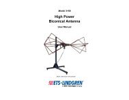
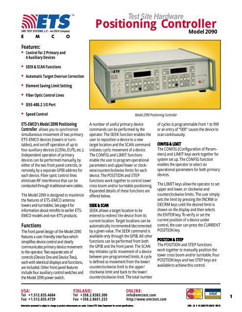
Test Site Hardware<br />
Positioning <strong>Controller</strong><br />
Speed Control Model <strong>2090</strong> Positioning <strong>Controller</strong><br />
<strong>ETS</strong>-EMCO’s Model <strong>2090</strong> Positioning<br />
<strong>Controller</strong> allows you to synchronize<br />
simultaneous movement of two primary<br />
<strong>ETS</strong>-EMCO devices (towers or turntables),<br />
and on/off operation of up to<br />
four auxiliary devices (LISNs, EUTs, etc.).<br />
Independent operation of primary<br />
devices can be performed manually, by<br />
either of the two front panel controls, or<br />
remotely, by a separate GPIB address for<br />
each device. Fiber optic control lines<br />
eliminate RF interference that can be<br />
conducted through traditional wire cables.<br />
The Model <strong>2090</strong> is designed to maximize<br />
the features of <strong>ETS</strong>-EMCO antenna<br />
towers and turntables. See page 4 for<br />
information about retrofits to earlier <strong>ETS</strong>-<br />
EMCO models and non-<strong>ETS</strong> products.<br />
Functions<br />
The front panel design of the Model <strong>2090</strong><br />
features a user-friendly interface which<br />
simplifies device control and clearly<br />
communicates primary device movement<br />
to the operator. Two separate sets of<br />
controls (Device One and Device Two),<br />
each with identical displays and functions,<br />
are included. Other front panel features<br />
include four auxiliary control switches and<br />
the Model <strong>2090</strong> power switch.<br />
A number of useful primary device<br />
commands can be performed by the<br />
operator. The SEEK function enables the<br />
user to reposition a device to a new<br />
target location and the SCAN command<br />
initiates cyclic movement of a device.<br />
The CONFIG and LIMIT functions<br />
enable the user to program operational<br />
parameters and upper/lower or clockwise/counterclockwise<br />
limits for each<br />
device. The POSITION and STEP<br />
functions work together to control tower<br />
cross boom and/or turntable positioning.<br />
Expanded details of these functions are<br />
offered below.<br />
SEEK SEEK & & SC SCAN SC SC AN<br />
SEEK allows a target location to be<br />
entered to redirect the device from its<br />
current location. Target locations can be<br />
automatically incremented/decremented<br />
by a given value. The SEEK command is<br />
available only through the GPIB. All other<br />
functions can be performed from both<br />
the GPIB and the front panel. The SCAN<br />
key initiates cyclic movement of a device<br />
between pre-programmed limits. A cycle<br />
is defined as movement from the lower/<br />
counterclockwise limit to the upper/<br />
clockwise limit and back to the lower/<br />
counterclockwise limit. The total number<br />
ONLINE:<br />
info@emctest.com<br />
http://www.emctest.com<br />
Model <strong>2090</strong><br />
of cycles is programmable from 1 to 999<br />
or an entry of “000” causes the device to<br />
scan continuously.<br />
CONFIG ONFIG & & LIMIT<br />
LIMIT<br />
The CONFIG (Configuration of Parameters)<br />
and LIMIT keys work together for<br />
system set up. The CONFIG function<br />
enables the operator to select six<br />
operational parameters for both primary<br />
devices.<br />
The LIMIT keys allow the operator to set<br />
upper and lower, or clockwise and<br />
counterclockwise limits. The user simply<br />
sets the limit by pressing the INCRM or<br />
DECRM keys until the desired limit is<br />
shown on the display and then selects<br />
the ENTER key. To verify or set the<br />
current position of a device under<br />
control, the user can press the CURRENT<br />
POSITION key.<br />
POSITION POSITION & & STEP<br />
STEP<br />
The POSITION and STEP functions<br />
work together to manually position the<br />
tower cross boom and/or turntable. Four<br />
POSITION keys and two STEP keys are<br />
available to achieve this control.<br />
Information Information presented presented is is subject subject to to change change as as product product enhancements enhancements are are made. made. Contact Contact <strong>ETS</strong> <strong>ETS</strong> Sales Sales Department Department for for current current specifications. specifications.<br />
2/00 2/00 - - 2k 2k S S © © 2000 2000 2000 <strong>ETS</strong>-EMCO <strong>ETS</strong>-EMCO REV REV B<br />
B<br />
1
POSITION POSITION KK<br />
Keys K<br />
UP / CW <br />
UP moves the tower cross boom upward.<br />
CW moves the turntable clockwise.<br />
DOWN / CCW<br />
<br />
DOWN moves the tower cross boom<br />
downward.<br />
CCW moves the turntable counterclockwise.<br />
STOP <br />
STOP ceases movement of device.<br />
POLARIZATION / FLOTATION/SPEED<br />
<br />
HOR / UP/ FAST<br />
VERT / DN / SLOW<br />
On a tower, pressing this button will toggle<br />
the tower cross boom between<br />
HORIZONTAL and VERTICAL polarization.<br />
On an air flotation turntable, pressing this<br />
button will toggle the UP (inflation) and<br />
DOWN (deflation) of the turntable top. On a<br />
two-speed turntable, pressing this button<br />
will toggle the speed of the turntable<br />
between FAST and SLOW. On a variable<br />
speed turntable, pressing this button will<br />
cycle the SPEED between four presets. The<br />
indicator lights will illuminate in a binary<br />
fashion to indicate the current preset speed<br />
selection i.e. first preset OFF-OFF, second<br />
preset ON-OFF, third preset OFF-ON, fourth<br />
preset ON-ON.<br />
STEP STEP K KKeys<br />
K<br />
INC<br />
INC moves the device up or clockwise.<br />
DEC<br />
DEC moves the device down or<br />
counterclockwise.<br />
USA:<br />
Tel +1.512.835.4684<br />
Fax +1.512.835.4729<br />
FINLAND:<br />
Tel +358.2.8383.300<br />
Fax +358.2.8651.233<br />
Test Site Hardware<br />
Positioning <strong>Controller</strong><br />
Front Panel Illustration – Model <strong>2090</strong> Positioning <strong>Controller</strong><br />
The controller will move the device in the<br />
desired direction as long as the key is<br />
pressed. The device will stop when the<br />
key is released.<br />
LOC OC OC OCAL/REMO<br />
OC AL/REMO AL/REMOTE AL/REMO TE OPER OPER OPERATION<br />
OPER OPER TION TION<br />
The Model <strong>2090</strong> can be operated<br />
manually from the front panel or<br />
remotely via the GPIB port. When the<br />
Model <strong>2090</strong> is addressed via the GPIB<br />
port, the RMT indicator light will<br />
illuminate and the ADDR indicator will<br />
flash to show bus activity. Pressing the<br />
LOCAL function key allows you to exit<br />
the remote mode. When the optional<br />
Hand Control Unit (see Options, page 3)<br />
is used, all position changes will be<br />
recorded and displayed by the Model<br />
<strong>2090</strong> <strong>Controller</strong>.<br />
AUXILIAR UXILIAR UXILIAR UXILIARY UXILIARY<br />
Y CC<br />
CONTR CC<br />
ONTR ONTROL ONTR OL<br />
Four front panel keys are available to<br />
control auxiliary devices. While in<br />
manual mode, you can activate an<br />
auxiliary device by pressing the AUX<br />
CONTROL key that corresponds to the<br />
auxiliary device port. In remote mode,<br />
auxiliary devices can be activated by using<br />
the appropriate GPIB command. The<br />
control lines are on/off output only. In<br />
order to use these four auxiliary lines, an<br />
interface box that will perform a custom<br />
function and accept a fiber optic<br />
ONLINE:<br />
info@emctest.com<br />
http://www.emctest.com<br />
Model <strong>2090</strong><br />
input, is needed. Contact <strong>ETS</strong>-EMCO<br />
Sales for details.<br />
Features<br />
Automatic Target Overrun Correction<br />
The Model <strong>2090</strong> constantly monitors<br />
inertia-induced target overrun. If<br />
overrun on turntables or towers occurs, it<br />
is identified and tracked. Utilizing a<br />
special algorithm, the Model <strong>2090</strong><br />
continually adjusts subsequent<br />
positionings to minimize overrun,<br />
allowing for proper device positioning<br />
during tests.<br />
Element Saving Limit Setting<br />
To prevent damage to antenna elements<br />
which may accidentally rotate into the<br />
ground plane or ceiling during polarization,<br />
the Model <strong>2090</strong> allows you to<br />
program two upper and two lower limit<br />
settings. These settings allow you to<br />
safely maximize antenna scan height in<br />
either horizontal or vertical polarization<br />
– especially useful with BiConiLogs TM ,<br />
biconicals, log periodics, and other<br />
antennas with protruding elements.<br />
Fiber Optic Input/Output Lines<br />
The <strong>2090</strong> features fiber optic control<br />
lines to eliminate conducted noise. Each<br />
primary device cable contains two fiber<br />
Information Information presented presented is is subject subject to to change change as as product product enhancements enhancements are are made. made. Contact Contact <strong>ETS</strong> <strong>ETS</strong> Sales Sales Department Department for for current current specifications. specifications.<br />
2/00 2/00 - - 2k 2k S S © © 2000 2000 2000 <strong>ETS</strong>-EMCO <strong>ETS</strong>-EMCO REV REV B<br />
B<br />
2
optic lines (transmit/receive). Auxiliary<br />
device lines are output only. Reliable and<br />
easy-to-use ST connectors are standard.<br />
GPIB<br />
The General Purpose Interface Bus<br />
(GPIB) complies with IEEE 488.1/488.2<br />
standards. All front panel functions can<br />
be exercised using GPIB commands<br />
while in the remote mode. GPIB commands<br />
are backward compatible with<br />
<strong>ETS</strong>-EMCO Model 1050, 1060 and 1090<br />
<strong>Controller</strong>s, simplifying upgrades to the<br />
new model. Model 1050 and 1060<br />
commands are compatible with Hewlett<br />
Packard's Model HP 85876A Commercial<br />
Radiated EMI Measurement Software<br />
and Rohde & Schwarz Model ES-KI EMI<br />
Measurement & Evaluation Software.<br />
Speed eed C CCon<br />
C Con<br />
on ontr ontr<br />
tr trol trol<br />
ol<br />
Users whose test facilities include a twospeed<br />
turntable will find the Model <strong>2090</strong><br />
positioning controller well suited to their<br />
needs. The unit’s SLOW control activates<br />
the turntable’s lower speed drive. The<br />
FAST control activates the turntable’s<br />
higher speed drive. The controller can be<br />
used for speed-control with <strong>ETS</strong>-EMCO<br />
turntables that feature dual speeds and<br />
other brands of two-speed turntables.<br />
Memory<br />
All settings in the Model <strong>2090</strong> are saved<br />
when the unit is turned off, allowing for<br />
easy set-up when testing is interrupted<br />
and returned to later.<br />
Precise Resolution<br />
Display accuracy on the Model <strong>2090</strong> is<br />
highly precise. The unit offers position<br />
readout increments of 1 mm for towers<br />
and 0.1 degree for turntables.<br />
Universal Power Supply<br />
The positioning controller has a convenient<br />
built-in auto ranging feature that<br />
automatically senses supply voltage. Any<br />
USA:<br />
Tel +1.512.835.4684<br />
Fax +1.512.835.4729<br />
Electrical Specifications<br />
FINLAND:<br />
Tel +358.2.8383.300<br />
Fax +358.2.8651.233<br />
Test Site Hardware<br />
Positioning <strong>Controller</strong><br />
AC power source input within the range<br />
of 115/230 VAC, 50/60 Hz can be used.<br />
Rack Mounting<br />
For convenience, the Model <strong>2090</strong> is<br />
standard rack width and 3U rack size.<br />
Standard Configuration<br />
<strong>Controller</strong> assembly<br />
IEC 320 power cord<br />
Manual<br />
Options<br />
Hand Control Unit<br />
The Hand Control Unit is designed to<br />
manually operate <strong>ETS</strong>-EMCO antenna<br />
towers and turntables. Lightweight and<br />
easy to operate, this convenient unit<br />
plugs into the motor base of the tower or<br />
turntable and enables you to perform<br />
simple manual movement of these<br />
devices. It works in tandem with <strong>ETS</strong>-<br />
EMCO’s Model <strong>2090</strong> <strong>Controller</strong>. Changes<br />
in position location made by the Hand<br />
Control Unit will be recorded and<br />
displayed by the Model <strong>2090</strong> <strong>Controller</strong>.<br />
To order, specify part number 105136.<br />
MODEL POWER FUSE BACK PANEL I/0<br />
<strong>2090</strong> 115/230 VAC 1 2 A 250 VAC Time Delay 8 fiber optic connectors.<br />
50/60 Hz IEEE-488.2 connector.<br />
IEC 320 power inlet.<br />
Fuse holder.<br />
1 Autoselect<br />
Physical Specifications<br />
MODEL WIDTH DEPTH 2 HEIGHT WEIGHT<br />
<strong>2090</strong> 43.8 cm 34.3 cm 13.3 cm 4.5 kg<br />
17.3 in 13.5 in 5.3 in 10.0 lb<br />
2 Excluding handles<br />
ONLINE:<br />
info@emctest.com<br />
http://www.emctest.com<br />
Model <strong>2090</strong><br />
Auxiliary Control Unit<br />
The Auxiliary Control Unit provides a<br />
means to remotely open and close<br />
contacts via fiber optic cable. These<br />
contacts can be used to remotely control<br />
power relays or other devices to automate<br />
EMC testing. Simplex fiber optic cable<br />
connects the output of the Model <strong>2090</strong><br />
Aux Control to the input of the Auxiliary<br />
Control Unit. The Auxiliary Control Unit<br />
is powered by a wall-mount power<br />
supply (user-specified 115 VAC or 230<br />
VAC at time of order).<br />
Additional Fiber Optic Cable<br />
Standard fiber optic cable length is 10<br />
meters. Custom lengths are available.<br />
To order, specify part number 708029-m<br />
(10 m increments).<br />
Fiber Optic Feedthrough<br />
Bulkhead feedthrough consisting of a<br />
wave-guide cutoff for fiber optic cable.<br />
To order, specify part number 105120.<br />
Rack Mount Rails<br />
A rack mount kit can be purchased for<br />
mounting the Model <strong>2090</strong> in a rack.<br />
To order, specify part number 540037.<br />
Information Information presented presented is is subject subject to to change change as as product product enhancements enhancements are are made. made. Contact Contact <strong>ETS</strong> <strong>ETS</strong> Sales Sales Department Department for for current current specifications. specifications.<br />
2/00 2/00 - - 2k 2k S S © © 2000 2000 2000 <strong>ETS</strong>-EMCO <strong>ETS</strong>-EMCO REV REV B<br />
B<br />
3
Positioning <strong>Controller</strong><br />
Upgrade Kits<br />
Now your older <strong>ETS</strong>-EMCO tower and<br />
turntable can operate with all of the new<br />
command features available with our<br />
Model <strong>2090</strong> Positioning <strong>Controller</strong>. All<br />
you need is our Retrofit-Kit and a Model<br />
<strong>2090</strong> <strong>Controller</strong> to replace your existing<br />
EMCO Model 1050, 1060, 1060C or 1090<br />
<strong>Controller</strong>. You'll be able to control two<br />
devices (tower or turntable) and four<br />
auxiliary devices at once, plus access the<br />
SEEK, SCAN, target overrun, and<br />
multiple limit functions. For a thorough<br />
description of all Model <strong>2090</strong> features<br />
and functions please turn to page one.<br />
Note: Bore Sight functions are only<br />
available with Model 2071 towers.<br />
To install the Retrofit-Kit, the included<br />
interface box is placed in line between<br />
the tower/ turntable motor box and<br />
Specifications<br />
USA:<br />
Tel +1.512.835.4684<br />
Fax +1.512.835.4729<br />
controller. Existing cables are used<br />
between the tower/turntable motor box<br />
and the Retrofit-Kit's interface box. Fiber<br />
optic cables are connected between the<br />
interface box and the new Model <strong>2090</strong><br />
Positioning <strong>Controller</strong>.<br />
Retrofit-Kit to replace<br />
Model 1050 or 1060 <strong>Controller</strong>s<br />
PN # 105637<br />
Retrofit-Kit to replace<br />
Model 1090 <strong>Controller</strong><br />
PN # 105797<br />
Retrofit-Kit for non-EMCO<br />
towers/turntables<br />
CALL FOR QUOTE<br />
All kits consist of an interface box with<br />
power cord and a 10 meter fiber optic<br />
cable.<br />
FINLAND:<br />
Tel +358.2.8383.300<br />
Fax +358.2.8651.233<br />
Options<br />
ONLINE:<br />
info@emctest.com<br />
http://www.emctest.com<br />
Custom length fiber optic cable<br />
Custom length wire cable<br />
Hand Control Unit<br />
MODEL PHYSICAL ELECTRICAL<br />
WIDTH DEPTH HEIGHT WEIGHT VOLTAGE Hz<br />
(SELECTABLE)<br />
Retrofit-Kit 35.6 cm 30.5 cm 16.5 cm 11.4 kg 115/230 50/60<br />
for 1050, 1060 14.0 in 12.0 in 6.5 in 25.2 lb<br />
Power to Model 1090<br />
Motor Box<br />
Existing (pre Model <strong>2090</strong>)<br />
Tower / Turntable<br />
Motor Box<br />
Optional<br />
Hand<br />
Control<br />
Unit<br />
Existing Cables<br />
(one cable on 1090 kit)<br />
Test Site Hardware<br />
Positioning <strong>Controller</strong><br />
Model <strong>2090</strong><br />
New<br />
Interface Box<br />
New<br />
Fiber Optic Cable<br />
Model <strong>2090</strong> <strong>Controller</strong><br />
Information Information presented presented is is subject subject to to change change as as product product enhancements enhancements are are made. made. Contact Contact <strong>ETS</strong> <strong>ETS</strong> Sales Sales Department Department for for current current specifications. specifications.<br />
2/00 2/00 - - 2k 2k S S © © 2000 2000 2000 <strong>ETS</strong>-EMCO <strong>ETS</strong>-EMCO REV REV B<br />
B<br />
4