The State of Antenna Calibration Standards in the ... - ETS-Lindgren
The State of Antenna Calibration Standards in the ... - ETS-Lindgren
The State of Antenna Calibration Standards in the ... - ETS-Lindgren

You also want an ePaper? Increase the reach of your titles
YUMPU automatically turns print PDFs into web optimized ePapers that Google loves.
THE ENGINEER’S GUIDE To<br />
WoRLDWIDE REGULAToRy<br />
CoMpLIANCE<br />
www.conformity.com<br />
Volume 13, Issue 11<br />
November 2008<br />
Conformity Magaz<strong>in</strong>e<br />
531 K<strong>in</strong>g Street, Suite 6<br />
Littleton, MA 01460<br />
CHANGE SERVICE REQUESTED<br />
Conformity®<br />
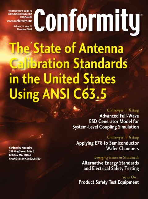
<strong>The</strong> <strong>State</strong> <strong>of</strong> <strong>Antenna</strong><br />
<strong>Calibration</strong> <strong>Standards</strong><br />
<strong>in</strong> <strong>the</strong> United <strong>State</strong>s<br />
Us<strong>in</strong>g ANSI C63.5 Challenges <strong>in</strong> Test<strong>in</strong>g<br />
Advanced Full-Wave<br />
ESD Generator Model for<br />
System-Level Coupl<strong>in</strong>g Simulation<br />
Challenges <strong>in</strong> Test<strong>in</strong>g<br />
Apply<strong>in</strong>g E78 to Semiconductor<br />
Wafer Chambers<br />
Emerg<strong>in</strong>g Issues <strong>in</strong> <strong>Standards</strong><br />
Alternative Energy <strong>Standards</strong><br />
and Electrical Safety Test<strong>in</strong>g<br />
Focus On...<br />
Product Safety Test Equipment
© Ir<strong>in</strong>a Igl<strong>in</strong>a | Dreamstime.com<br />
<strong>The</strong> <strong>State</strong> <strong>of</strong><br />
<strong>Antenna</strong> <strong>Calibration</strong> <strong>Standards</strong><br />
<strong>in</strong> <strong>the</strong> United <strong>State</strong>s Us<strong>in</strong>g<br />
ANSI C63.5<br />
by Mike W<strong>in</strong>dler, Underwriters Laboratories,<br />
Zhong Chen, <strong>ETS</strong>-L<strong>in</strong>dgren,<br />
and Dennis Camell, National Institute <strong>of</strong> <strong>Standards</strong> and Technology<br />
November 2008 CoNformity
Methods for calibrat<strong>in</strong>g antennas have been around<br />
s<strong>in</strong>ce antennas were first used. Over <strong>the</strong> years our<br />
understand<strong>in</strong>g <strong>of</strong> antennas and <strong>the</strong>ir performance<br />
<strong>in</strong> <strong>the</strong>ir <strong>in</strong>tended applications has cont<strong>in</strong>ued to evolve. In<br />
this article we seek to discuss <strong>the</strong> past, present, and future<br />
state <strong>of</strong> our antenna calibration work <strong>in</strong> <strong>the</strong> Accredited<br />
<strong>Standards</strong> Committee C63 ® (ASC C63 ® ), which has resulted<br />
<strong>in</strong> <strong>the</strong> publication <strong>of</strong> <strong>the</strong> American National Standard, C63.5<br />
“Radiated Emission Measurements <strong>in</strong> Electromagnetic<br />
Interference (EMI) Control–<strong>Calibration</strong> <strong>of</strong> <strong>Antenna</strong>s (9 kHz<br />
to 40 GHz).” This work is performed by experts <strong>in</strong> ASC C63 ®<br />
which ma<strong>in</strong>ta<strong>in</strong>s <strong>the</strong> currency <strong>of</strong> ANSI C63.5.<br />
Don Heirman, chairman <strong>of</strong> ASC C63 ® , believes that this<br />
article presents a major step forward <strong>in</strong> <strong>the</strong> understand<strong>in</strong>g <strong>of</strong><br />
what ASC C63 ® has and will be do<strong>in</strong>g <strong>in</strong> br<strong>in</strong>g<strong>in</strong>g <strong>the</strong> latest<br />
<strong>the</strong>ory and technology forward <strong>in</strong> <strong>the</strong> antenna calibration area.<br />
He also believes that ASC C63 ® is <strong>in</strong> a unique place to support<br />
this work, as its membership is from <strong>in</strong>dustry, regulatory<br />
bodies, military, universities, and consultants located <strong>in</strong><br />
<strong>the</strong> U.S. It is this broad representation that lends itself to<br />
robust standards such as ANSI C63.5 as it is reviewed by <strong>the</strong><br />
committee membership. This <strong>the</strong>n lends itself to provide its<br />
expertise to <strong>the</strong> work be<strong>in</strong>g done <strong>in</strong>ternationally <strong>in</strong> <strong>the</strong> Special<br />
International Committee on Radio Interference (CISPR).<br />
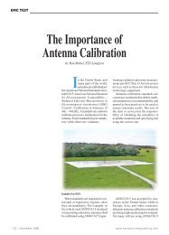
Figure 1: <strong>The</strong> late Al Smith is shown <strong>in</strong> his <strong>of</strong>fice at IBM.<br />
Mr. Smith’s paper “Calculation <strong>of</strong> Site Attenuation from<br />
<strong>Antenna</strong> Factors,” coauthored with R. F. German and J. B. Pate,<br />
was recognized as one <strong>of</strong> <strong>the</strong> top ten “Most Referenced”<br />
Transactions papers <strong>in</strong> <strong>the</strong> 50-year history <strong>of</strong> <strong>the</strong> IEEE EMC Society.<br />
This article leads <strong>the</strong> reader through <strong>the</strong> history <strong>of</strong> <strong>the</strong> work on<br />
ANSI C63.5, from its beg<strong>in</strong>n<strong>in</strong>g to <strong>the</strong> latest version that was<br />
published <strong>in</strong> 2006, and on to <strong>the</strong> future.<br />
Historical Roots<br />
<strong>The</strong> predom<strong>in</strong>ant method currently used to calibrate antennas<br />
<strong>in</strong> <strong>the</strong> frequency range <strong>of</strong> 30-1000 MHz is based on <strong>the</strong> work<br />
<strong>of</strong> Albert Smith [1] dat<strong>in</strong>g back to <strong>the</strong> early 1980s when he<br />
provided his expertise <strong>in</strong> ASC C63 ® . A companion article<br />
was published at <strong>the</strong> same time by Smith et al [2] on <strong>the</strong><br />
calculation <strong>of</strong> normalized site attenuation us<strong>in</strong>g antenna<br />
factors. Toge<strong>the</strong>r, <strong>the</strong>se articles <strong>in</strong>terlaced antenna calibrations<br />
and site attenuation for <strong>the</strong> foreseeable future.<br />
Figure 1 shows a photo <strong>of</strong> <strong>the</strong> late Al Smith. <strong>The</strong>re is an<br />
explicit recognition <strong>in</strong> [1] that <strong>the</strong> antenna factors measured<br />
us<strong>in</strong>g <strong>the</strong> standard site method depend on <strong>the</strong> site attenuation<br />
with <strong>the</strong> quote “<strong>The</strong> standard-site method <strong>of</strong> determ<strong>in</strong><strong>in</strong>g<br />
antenna factors is based on site attenuation measurements<br />
made on a near ideal, open-field site.” However, how do<br />
we determ<strong>in</strong>e if a test site is a near ideal site? Answer: By<br />
measur<strong>in</strong>g <strong>the</strong> site us<strong>in</strong>g antenna factors! This catch 22<br />
scenario has always been a source <strong>of</strong> concern <strong>in</strong> some parts<br />
<strong>of</strong> <strong>the</strong> EMC community. None<strong>the</strong>less, efforts have been made<br />
through <strong>the</strong> standards process to reconcile this concern.<br />
Several technical issues were recognized <strong>in</strong> <strong>the</strong>se sem<strong>in</strong>al<br />
articles. Those technical issues <strong>in</strong>cluded restrictions on <strong>the</strong><br />
measurement geometry discussed <strong>in</strong> [1]. Smith identified:<br />
1.<br />
2.<br />
3.<br />
Measurement distance as a concern to m<strong>in</strong>imize antennato-antenna<br />
coupl<strong>in</strong>g and near field effects;<br />
<strong>The</strong> need to keep antenna heights (both transmitt<strong>in</strong>g and<br />
receiv<strong>in</strong>g) high enough to m<strong>in</strong>imize antenna-to-ground<br />
plane mutual impedances and to ensure a negligible<br />
contribution from <strong>the</strong> surface-wave component <strong>of</strong> <strong>the</strong><br />
ground wave;<br />
<strong>The</strong> preference <strong>of</strong> horizontal over vertical polarity<br />
calibrations because “mutual coupl<strong>in</strong>g between <strong>the</strong><br />
antenna and <strong>the</strong> orthogonal transmission l<strong>in</strong>e is negligible,<br />
calculations <strong>of</strong> <strong>the</strong> horizontal ground wave are simpler<br />
than calculations for <strong>the</strong> vertical ground wave, <strong>the</strong><br />
surface-wave component for horizontal ground wave<br />
over earth is more tightly coupled to <strong>the</strong> surface, and <strong>the</strong><br />
horizontal ground wave is less sensitive to differences<br />
<strong>in</strong> surface conductivity and permittivity than <strong>the</strong> vertical<br />
wave.”<br />
Due to <strong>the</strong> reciprocity <strong>of</strong> antenna calibrations and site<br />
attenuation, <strong>the</strong>se concerns also represent sources <strong>of</strong> error<br />
<strong>in</strong> normalized site attenuation measurements. <strong>The</strong> standards<br />
consensus process, as always, is used to f<strong>in</strong>d acceptable<br />
compromises to such concerns, and <strong>in</strong> 1988 ASC C63 ®<br />
drafted <strong>the</strong> first antenna calibration standard, C63.5 [3]. Site<br />
attenuation was also added to ANSI C63.4 [4] soon <strong>the</strong>reafter.<br />
November 2008 CoNformity 2
This first draft <strong>of</strong> ANSI C63.5 recognized <strong>the</strong> need for an<br />
immediate alert, by recommend<strong>in</strong>g that antennas used to<br />
measure site attenuation not be calibrated on <strong>the</strong> same site<br />
to be evaluated. This first edition <strong>of</strong> C63.5 simply stated<br />
that <strong>the</strong> standard site method <strong>in</strong>volved three site attenuation<br />
measurements. Later editions would refer to tak<strong>in</strong>g three<br />
“<strong>in</strong>sertion loss measurements.”<br />
Dur<strong>in</strong>g <strong>the</strong> ensu<strong>in</strong>g years, efforts were made to get <strong>the</strong><br />
<strong>in</strong>ternational community to adopt ANSI C63.5 as an<br />
<strong>in</strong>ternational standard for <strong>the</strong> calibration <strong>of</strong> antennas with<strong>in</strong><br />
CISPR 16. It turns out that this adoption almost happened well<br />
over a decade ago but, for several reasons, it did not “make <strong>the</strong><br />
cut”.<br />
Several concerns were raised, <strong>in</strong>clud<strong>in</strong>g <strong>the</strong> fact that <strong>the</strong><br />
standard allowed for vertical polarizations and did not<br />
explicitly restrict such measurements. In addition, <strong>the</strong><br />
<strong>in</strong>ternational community considered 3-meter calibration<br />
distances <strong>in</strong>sufficient to reduce antenna-to-antenna coupl<strong>in</strong>g.<br />
This issue was implicitly addressed <strong>in</strong> ANSI C63.4 with <strong>the</strong><br />
addition <strong>of</strong> mutual coupl<strong>in</strong>g correction factors for dipole<br />
antennas used <strong>in</strong> normalized site attenuation test<strong>in</strong>g (Table<br />
4 <strong>of</strong> [4]). <strong>The</strong> 1998 edition <strong>of</strong> C63.5 <strong>in</strong>cluded 10-meter<br />
calibration distances and explicitly removed vertical antenna<br />
calibrations as CISPR was lean<strong>in</strong>g to this approach.<br />
This resulted <strong>in</strong> un<strong>in</strong>tended consequences for site<br />
measurements. <strong>The</strong> use <strong>of</strong> horizontal antenna calibrations<br />
for vertical polarity site attenuation measurements assumes<br />
<strong>the</strong> issues 1-3 raised by Smith <strong>in</strong> 1982 were <strong>in</strong>significant.<br />
This assumption was cast <strong>in</strong>to doubt <strong>in</strong> light <strong>of</strong> <strong>the</strong> ±4 dB test<br />
site criteria <strong>in</strong> [5]. <strong>The</strong> errors, once thought to be negligible,<br />
needed to be redressed, as <strong>the</strong>y represented between 1 and 2.8<br />
dB <strong>of</strong> <strong>the</strong> ±4 dB test site criteria.<br />
<strong>The</strong>se errors were corrected <strong>in</strong> <strong>the</strong> 2004 edition <strong>of</strong> ANSI<br />
C63.5, which <strong>in</strong>troduced numerical corrections for biconical<br />
dipole antennas and an alternative method for o<strong>the</strong>r hybrid<br />
Notice <strong>of</strong> Upcom<strong>in</strong>g Workshop<br />
A workshop will be held on ANSI C63.5 - <strong>Antenna</strong> <strong>Calibration</strong> -<br />
on Saturday, August 15, 2009, just prior to <strong>the</strong> 2009 IEEE<br />
International Symposium on EMC <strong>in</strong> Aust<strong>in</strong>, Texas. Held at<br />
<strong>ETS</strong>-L<strong>in</strong>dgren <strong>in</strong> nearby Cedar Park, <strong>the</strong> workshop will consist<br />
<strong>of</strong> lectures by Don Heirman <strong>of</strong> Don HEIRMAN Consultants,<br />
Chair <strong>of</strong> ANSI ASC C63, Mike W<strong>in</strong>dler <strong>of</strong> UL, Chair <strong>of</strong> ANSI<br />
ASC C63 Subcommittee 1 on “Techniques and Development”<br />
and Dennis Camell <strong>of</strong> NIST, Chair <strong>of</strong> <strong>the</strong> Work<strong>in</strong>g Group for<br />
revisions to ANSI C63.5. Attendees will have <strong>the</strong> opportunity<br />
to apply what <strong>the</strong>y learn via problem solv<strong>in</strong>g and perform<strong>in</strong>g<br />
an antenna calibration us<strong>in</strong>g <strong>ETS</strong>-L<strong>in</strong>dgren’s expansive<br />
ISO 17205 certified open area test site and A2LA-accredited<br />
calibration lab. Registration <strong>in</strong>formation will be available on<br />
www.c63.org and www.emc2009.org after January 1, 2009.<br />
antennas used to measure site attenuation. This alternative<br />
method <strong>in</strong>cluded fur<strong>the</strong>r restriction on reference sites used to<br />
calibrate antennas to be used <strong>in</strong> site validations.<br />
Technical Drawbacks <strong>in</strong> Earlier Versions<br />
To review, <strong>the</strong> Standard Site Method (SSM) and Normalized<br />
Site Attenuation (NSA) were first <strong>in</strong>troduced by Smith et al.<br />
<strong>in</strong> 1982 [1, 2] <strong>in</strong> a pair <strong>of</strong> complementary papers noted above.<br />
<strong>The</strong> methods were adopted <strong>in</strong> ANSI C63.5-1988/C63.4-1992.<br />
It was a leap forward for EMC antenna calibration and site<br />
validation measurements, as <strong>the</strong>y provided a standard way<br />
for calibrat<strong>in</strong>g EMC antennas. This had proved to be quite<br />
challeng<strong>in</strong>g until <strong>the</strong>n because <strong>of</strong> <strong>the</strong> wide frequency ranges<br />
and relatively low ga<strong>in</strong>s (thus wide beamwidths) <strong>of</strong> <strong>the</strong>se<br />
antennas. SSM was quickly adopted worldwide as <strong>the</strong> most<br />
popular EMC antenna calibration method.<br />
<strong>The</strong> basic idea <strong>of</strong> SSM is quite simple. <strong>The</strong> method builds<br />
upon <strong>the</strong> far field Friis transmission equation, and adds a ray<br />
trac<strong>in</strong>g component from <strong>the</strong> ground bounce <strong>of</strong> <strong>the</strong> wave over<br />
<strong>the</strong> conduct<strong>in</strong>g ground plane used for <strong>the</strong>se calibrations. Even<br />
though a ground plane is used, <strong>the</strong> standard site method <strong>in</strong><br />
recent times now aims to produce free-space antenna factors<br />
by remov<strong>in</strong>g <strong>the</strong> ground effect ma<strong>the</strong>matically. <strong>The</strong> ground<br />
plane was <strong>in</strong>troduced at <strong>the</strong> start to provide a repeatable,<br />
consistent, and predictable reference. To avoid signal nulls<br />
caused by <strong>the</strong> cancel<strong>in</strong>g <strong>of</strong> <strong>the</strong> ground-bounced and <strong>the</strong> direct<br />
rays, one <strong>of</strong> <strong>the</strong> antennas is scanned from 1 m to 4 m <strong>in</strong> height.<br />
Only <strong>the</strong> maximum response is kept as <strong>the</strong> base for calibration.<br />
NSA measurements for site validation tests are a reverse <strong>of</strong><br />
<strong>the</strong> SSM for antenna calibrations. In this case, <strong>the</strong> antenna<br />
factors are known, and site performance can be compared<br />
with a <strong>the</strong>oretical value to gauge its fitness (with<strong>in</strong> ±4 dB as<br />
<strong>in</strong>dicated <strong>in</strong> ANSI C63.6 [6]). NSA is def<strong>in</strong>ed to be <strong>the</strong> site<br />
attenuation (path loss between <strong>the</strong> antennas over <strong>the</strong> ground<br />
plane <strong>in</strong> decibels) subtracted from <strong>the</strong> antenna factors <strong>of</strong> <strong>the</strong><br />
two antennas <strong>in</strong>volved.<br />
To make <strong>the</strong> Smith formulation work, several assumptions had<br />
to be made:<br />
•<br />
•<br />
•<br />
•<br />
Recall<strong>in</strong>g <strong>the</strong> formulation is based on <strong>the</strong> free-space farfield<br />
Friis equation, <strong>the</strong> antennas are assumed to be <strong>in</strong> <strong>the</strong><br />
far field <strong>of</strong> each o<strong>the</strong>r. Near field terms are not considered.<br />
To ma<strong>the</strong>matically remove <strong>the</strong> ground bounce, <strong>the</strong> antenna<br />
pattern had to be known a priori. S<strong>in</strong>ce <strong>the</strong>y are not known,<br />
all antennas are assumed to have <strong>the</strong> same pattern as a<br />
po<strong>in</strong>t dipole; i.e., with <strong>the</strong> well-known donut shape.<br />
Mutual coupl<strong>in</strong>gs among antennas and <strong>the</strong>ir ground images<br />
are not considered <strong>in</strong> <strong>the</strong> formula, and thus assumed to be<br />
negligible.<br />
<strong>Antenna</strong>s are considered to be physically small, so that <strong>the</strong><br />
whole <strong>of</strong> <strong>the</strong> receiv<strong>in</strong>g antenna is considered immersed <strong>in</strong> a<br />
uniform field.<br />
November 2008 CoNformity
• <strong>The</strong> separation distance is assumed to be known, which is and anechoic chamber manufactures got around <strong>the</strong> limitations<br />
<strong>the</strong> same as that <strong>of</strong> <strong>the</strong> two <strong>the</strong>oretical po<strong>in</strong>t dipoles. caused by <strong>the</strong>se imperfect assumptions <strong>in</strong> <strong>the</strong> <strong>the</strong>oretical<br />
model by us<strong>in</strong>g <strong>the</strong> so called “geometry-specific antenna<br />
factors.”<br />
<strong>The</strong>se assumptions work well for some geometries, such as<br />
<strong>in</strong> <strong>the</strong> case <strong>of</strong> biconical antennas at 10 m separation distance,<br />
horizontal polarization, and <strong>the</strong> transmit antenna at 2 m height.<br />
However, for site validation measurements over a volume<br />
occupied by <strong>the</strong> equipment under test, NSA as def<strong>in</strong>ed <strong>in</strong><br />
ANSI C63.4 <strong>in</strong>volves four geometries per separation distance<br />
(two antenna heights <strong>in</strong> horizontal and two heights <strong>in</strong> vertical<br />
polarization).<br />
It was quickly realized by many <strong>in</strong>volved <strong>in</strong> site validation<br />
tests that errors due to <strong>the</strong>se assumptions may be so large<br />
(<strong>the</strong>y can be on <strong>the</strong> order <strong>of</strong> 3 or 4 dB <strong>in</strong> some <strong>in</strong>stances) that<br />
<strong>the</strong>y overwhelm and obfuscate <strong>the</strong> true site performance.<br />
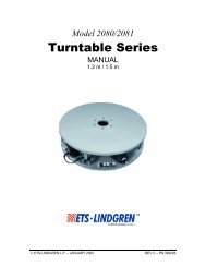
An example <strong>of</strong> an OATS is shown <strong>in</strong> Figure 2. As shown<br />
<strong>in</strong> Figure 3, for example, a perfect site would fail <strong>the</strong> NSA<br />
measurement if only free-space AFs are allowed when<br />
measured with a pair <strong>of</strong> common biconical antennas. Test labs<br />
Figure 2: An example <strong>of</strong> an Open Area Test Site (OATS) used for<br />
calibrat<strong>in</strong>g antennas (photo courtesy <strong>of</strong> <strong>ETS</strong>-L<strong>in</strong>dgren)<br />
Figure 3: Measured NSA on an open area test site and numerically<br />
simulated NSA on a <strong>the</strong>oretical perfect site (vertical polarization,<br />
R=3 m, h1=1 m, and h2= 1~4 m), both by us<strong>in</strong>g free-space AFs<br />
In practice, people first calibrated <strong>the</strong>ir antennas at all<br />
geometries required by NSA measurements, and generated<br />
antenna factors (us<strong>in</strong>g <strong>the</strong> SSM) for <strong>the</strong>se specific setups. Of<br />
course, <strong>the</strong>se antenna factors have <strong>the</strong> errors (caused by <strong>the</strong><br />
above assumptions) built <strong>in</strong>. When <strong>the</strong> NSA measurements<br />
were performed, <strong>the</strong>se same antenna factors were plugged<br />
back <strong>in</strong>to <strong>the</strong> NSA formula. Realiz<strong>in</strong>g that NSA procedures<br />
are just <strong>the</strong> reverse <strong>of</strong> <strong>the</strong> antenna calibration process, <strong>the</strong><br />
same errors cancel out.<br />
In reality, this is exactly <strong>the</strong> same as a site-to-site comparison<br />
method. Users end up compar<strong>in</strong>g <strong>the</strong> site attenuation <strong>of</strong> <strong>the</strong><br />
site-under-test to <strong>the</strong> site where <strong>the</strong> antenna calibrations were<br />
performed. Any <strong>of</strong> <strong>the</strong> ma<strong>the</strong>matical calculations <strong>in</strong>volv<strong>in</strong>g<br />
<strong>the</strong>oretical NSA and antenna factors are unnecessary (as<br />
<strong>the</strong>y cancel out) when us<strong>in</strong>g <strong>the</strong> “geometry-specific antenna<br />
factors.”<br />
In <strong>the</strong> late 1990s, a drive to use free-space antenna factors for<br />
product test<strong>in</strong>g was ga<strong>in</strong><strong>in</strong>g momentum, both domestically<br />
and <strong>in</strong>ternationally. This is because free-space AFs provide<br />
a good average value when <strong>the</strong>se antennas are scanned over<br />
1-4 m above a conduct<strong>in</strong>g ground plane. ANSI C63.5-1998<br />
was published to harmonize with <strong>the</strong> CISPR standards. In <strong>the</strong><br />
1998 release, antennas can only be calibrated <strong>in</strong> <strong>the</strong> near-freespace<br />
setup (10 m separation/horizontal polarization/transmit<br />
antenna at 2 m height). It is called near-free-space because <strong>the</strong><br />
SSM assumptions give rise to very small errors (less than<br />
0.5 dB).<br />
This, however, becomes a big problem for users who adopted<br />
“geometry-specific antenna factors,” as no o<strong>the</strong>r geometries<br />
are allowed for calibration. An ad hoc group was quickly<br />
formed <strong>in</strong> 1998 to address <strong>the</strong> situation. <strong>The</strong> group later<br />
became a work<strong>in</strong>g group (WG 1-15.6) <strong>in</strong> Subcommittee 1<br />
which reports to ASC C63 ® . It was noted that <strong>the</strong> “geometryspecific<br />
AF” is noth<strong>in</strong>g more than a site-to-site comparison<br />
and, to make <strong>the</strong> method consistent, a “golden site” would<br />
be needed to complete <strong>the</strong> <strong>the</strong>ory. <strong>The</strong>re was a great deal <strong>of</strong><br />
reluctance to <strong>the</strong> “golden site” concept because <strong>of</strong> practical<br />
concerns. Incidentally, SSM/NSA was embraced orig<strong>in</strong>ally to<br />
avoid a site-to-site comparison method. A different approach<br />
was now preferred.<br />
As it turns out, Albert Smith had realized some limitations <strong>in</strong><br />
his method. He addressed <strong>the</strong>m by provid<strong>in</strong>g mutual coupl<strong>in</strong>g<br />
correction factors for dipole antennas <strong>in</strong> his sem<strong>in</strong>al<br />
SSM/NSA papers. In ANSI C63.5-1988, correction factors for<br />
Roberts’ dipole were already <strong>in</strong>cluded. Due to <strong>the</strong> precedent,<br />
and realiz<strong>in</strong>g <strong>the</strong> fact that broadband antennas are most widely<br />
used for site validation measurements, <strong>the</strong> work<strong>in</strong>g group<br />
adopted numerical correction factors for broadband antennas.<br />
<strong>The</strong> NEC2 code [7] was used for <strong>the</strong> numerical simulation, as<br />
November 2008 CoNformity
its accuracy had been verified extensively <strong>in</strong> many scientific<br />
studies. <strong>The</strong>se correction factors are referred to as geometryspecific<br />
correction factors (GSCF) which is not an antenna<br />
factor correction, but a correction to NSA.<br />
Site performance issues typically happen <strong>in</strong> <strong>the</strong> frequency<br />
range <strong>of</strong> a biconical antenna. EMC biconical antennas<br />
from various manufacturers have almost identical physical<br />
appearance and dimensions because <strong>the</strong>y followed <strong>the</strong> orig<strong>in</strong>al<br />
design <strong>in</strong> MIL-STD-461 (published <strong>in</strong> 1968) and restated <strong>in</strong><br />
ANSI C63.5. This is convenient because unified correction<br />
factors can be provided. In <strong>the</strong> standards, some limits are<br />
provided on how much an antenna can deviate from <strong>the</strong>se<br />
dimensions. Virtually all available biconical antennas meet <strong>the</strong><br />
requirements.<br />
Additionally, GSCF depends on <strong>the</strong> impedance <strong>of</strong> <strong>the</strong> baluns.<br />
ANSI C63.5 provides corrections for both 50 ohm (1:1<br />
impedance transformation ratio) and 200 ohm (4:1 ratio)<br />
baluns. <strong>The</strong>se results were verified aga<strong>in</strong>st a wide range <strong>of</strong><br />
commercially available antennas [8].<br />
A benefit <strong>of</strong> <strong>the</strong> GSCF approach versus <strong>the</strong> site-to-site<br />
comparison method is that only free-space antenna factors<br />
are needed for site validation measurements. Geometryspecific<br />
<strong>in</strong>fluences are all <strong>in</strong>cluded <strong>in</strong> <strong>the</strong> GSCF. With a<br />
site-to-site comparison method, one would have to first f<strong>in</strong>d<br />
a “golden site,” and <strong>the</strong>n perform reference measurements<br />
<strong>in</strong> all geometries (currently a total <strong>of</strong> eight geometries for 3<br />
m and 10 m separations). With <strong>the</strong> GSCF method, antenna<br />
calibration is performed only <strong>in</strong> a s<strong>in</strong>gle geometry that is<br />
<strong>the</strong> near-free-space setup (or any alternative method which<br />
produces free-space AF). This greatly cuts down <strong>the</strong> time and<br />
hence <strong>the</strong> cost associated with site validation measurements,<br />
as well as reduc<strong>in</strong>g <strong>the</strong> chance for and sources <strong>of</strong> additional<br />
measurement uncerta<strong>in</strong>ties.<br />
An <strong>of</strong>ten-cited criticism <strong>of</strong> <strong>the</strong> SSM, besides <strong>the</strong> listed<br />
shortcom<strong>in</strong>gs from <strong>the</strong> assumptions, is that, for calibrations<br />
us<strong>in</strong>g three antennas, one antenna is at a fixed height <strong>in</strong><br />
one measurement, while scanned <strong>in</strong> height <strong>in</strong> ano<strong>the</strong>r<br />
measurement. S<strong>in</strong>ce antenna factor is height dependent, we are<br />
try<strong>in</strong>g to solve four unknowns with only three equations.<br />
This problem, along with <strong>the</strong> ones caused by o<strong>the</strong>r imperfect<br />
assumptions, is solved by <strong>the</strong> <strong>in</strong>troduction <strong>of</strong> GSCF.<br />
Intuitively, it can be understood as follows - <strong>the</strong> full-wave<br />
simulation <strong>in</strong>cludes all effects which corrects for any errors <strong>in</strong><br />
<strong>the</strong> Smith model. Actually, GSCF bypasses <strong>the</strong> Smith model.<br />
It employs <strong>the</strong> numerical model as <strong>the</strong> base <strong>in</strong>stead. When<br />
max 1 one works out <strong>the</strong> algebra, any <strong>of</strong> <strong>the</strong> E calculations <strong>in</strong> <strong>the</strong><br />
d<br />
Smith model drop out, leav<strong>in</strong>g only <strong>the</strong> free-space AFs and<br />
1 Ed<br />
max is a <strong>the</strong>oretical parameter proposed by Smith for <strong>the</strong> purpose<br />
<strong>of</strong> calculat<strong>in</strong>g <strong>the</strong>oretical NSA above a conduct<strong>in</strong>g ground plane. It<br />
represents <strong>the</strong> maximum E field (dB µV/m) at <strong>the</strong> receive antenna<br />
position dur<strong>in</strong>g height scann<strong>in</strong>g for a half-wave dipole with 1 pW <strong>of</strong><br />
radiated power.<br />
numerical geometry correction terms. <strong>The</strong> Smith formulation<br />
is not necessary <strong>in</strong> <strong>the</strong> GSCF method. It is <strong>in</strong>cluded as a<br />
historical artifact.<br />
<strong>The</strong> latest edition <strong>of</strong> ANSI C63.5 provides a measurement<br />
approach to obta<strong>in</strong> GSCF when numerical values are<br />
unavailable. This is described <strong>in</strong> Annex H <strong>of</strong> C63.5. This<br />
method <strong>in</strong>volves measur<strong>in</strong>g <strong>the</strong> same pair <strong>of</strong> antennas on a<br />
reference site at different geometries. This boils down to a<br />
site-to-site comparison with some extra constants present.<br />
Unlike <strong>the</strong> earlier uncontrolled site-to-site comparison method,<br />
Annex H requires that <strong>the</strong> pair <strong>of</strong> antennas be measured at<br />
least five times on different parts <strong>of</strong> <strong>the</strong> reference site. <strong>The</strong><br />
standard deviation from <strong>the</strong>se 5 measurements needs to be<br />
with<strong>in</strong> a certa<strong>in</strong> range for <strong>the</strong> site to qualify as a reference site.<br />
In addition, <strong>the</strong> reference site has to meet several physical<br />
specifications <strong>in</strong>clud<strong>in</strong>g size and flatness.<br />
Log periodic dipole arrays, or log antennas, are also common<br />
for EMC applications. Unified correction factors are not<br />
feasible, as log antennas vary greatly by manufacturer make<br />
and model. A different approach is under consideration, which<br />
is modified from <strong>the</strong> Smith model. This is called complex<br />
fit NSA (CFNSA). It fits measured site attenuation data vs.<br />
receiv<strong>in</strong>g antenna height to a ma<strong>the</strong>matical model <strong>in</strong> an effort<br />
to solve for log antenna phase center positions and antenna<br />
patterns. Vary<strong>in</strong>g phase center position and antenna pattern<br />
deviations from that <strong>of</strong> a po<strong>in</strong>t dipole are <strong>the</strong> dom<strong>in</strong>ant error<br />
sources for log antennas <strong>in</strong> <strong>the</strong> Smith model. CFNSA does not<br />
make assumptions on ei<strong>the</strong>r parameter. Interested readers are<br />
referred to [9, 10] for more <strong>in</strong>formation.<br />
Changes, Present Vision and Future Plans<br />
<strong>The</strong> latest revision <strong>of</strong> ANSI C63.5 has a number <strong>of</strong> major<br />
changes from previous editions and hence <strong>the</strong> 2006 edition<br />
must be used solely. Most <strong>of</strong> <strong>the</strong>se were added as normative<br />
annexes.<br />
<strong>The</strong> primary additions relate to free-space antenna factors<br />
(FSAF), geometry-specific correction factors (GSCF), <strong>the</strong><br />
use <strong>of</strong> a standard antenna calibration site (SACS), and an<br />
<strong>in</strong>formative annex on uncerta<strong>in</strong>ty. <strong>The</strong>se topics improve <strong>the</strong><br />
technical accuracy and repeatability <strong>of</strong> <strong>the</strong> measurement<br />
methods described, and address <strong>the</strong> compatibility with<br />
<strong>in</strong>ternational standards. However, <strong>the</strong>re still seems to be an<br />
occasional misunderstand<strong>in</strong>g as to <strong>the</strong> proper use <strong>of</strong> ANSI<br />
C63.5 document, which we will now explore.<br />
From <strong>the</strong> latest version <strong>of</strong> C63.5, <strong>the</strong>re are two sets <strong>of</strong> data<br />
needed when us<strong>in</strong>g EMC antennas. <strong>The</strong>se are related to each<br />
o<strong>the</strong>r, as expla<strong>in</strong>ed above. One data set is for product test<strong>in</strong>g<br />
and, by <strong>in</strong>ternational consensus, is <strong>the</strong> FSAF. This means that<br />
<strong>the</strong>re is only one AF for one antenna. <strong>The</strong> o<strong>the</strong>r set <strong>of</strong> data is<br />
used when determ<strong>in</strong><strong>in</strong>g test site validation. FSAF and GSCF<br />
are comb<strong>in</strong>ed to account for <strong>the</strong> effects <strong>of</strong> geometry <strong>in</strong> <strong>the</strong>se<br />
NSA measurements.<br />
November 2008 CoNformity
If <strong>the</strong> <strong>The</strong> antenna subject is <strong>of</strong> to ANSI be used C63.5 for is product calibration test<strong>in</strong>g, <strong>of</strong> antennas <strong>the</strong>n <strong>the</strong> used freespace<br />
to AF measure is used radiated to determ<strong>in</strong>e electric <strong>the</strong> fields. emission This standard levels for also both<br />
horizontal recognizes and <strong>the</strong> vertical need polarizations. to def<strong>in</strong>e and provide <strong>The</strong> SSM procedures provides near<br />
free-space for labs AFs (both that calibration are acceptable labs as as-is well if as no test<strong>in</strong>g corrections labs<br />
are that provided. wish to C63.5-2006 perform <strong>the</strong>ir [11] own currently antenna has calibration) corrections for<br />
biconical perform<strong>in</strong>g dipoles, antenna and is calibrations work<strong>in</strong>g on to application determ<strong>in</strong>e <strong>of</strong> <strong>the</strong> free-space associated<br />
corrections measurement for o<strong>the</strong>r uncerta<strong>in</strong>ty types <strong>of</strong> required antennas. <strong>in</strong> calibration reports.<br />
<strong>The</strong> <strong>The</strong> rationale uncerta<strong>in</strong>ty for hav<strong>in</strong>g is related a stricter by both NSA systematic requirement and than random <strong>the</strong><br />
usual error ±4 over dB is <strong>the</strong> for frequency <strong>the</strong> antenna range calibration <strong>of</strong> calibration. site to Depend<strong>in</strong>g conform<br />
tighter on <strong>the</strong> to <strong>the</strong>oretical method <strong>of</strong> NSA, calibration s<strong>in</strong>ce (Standard any error Site that Method <strong>the</strong> site might (SSM),<br />
<strong>in</strong>troduce Reference from <strong>Antenna</strong> <strong>the</strong> <strong>the</strong>oretical Method value (RAM) would or <strong>the</strong> propagate Equivalent through<br />
all <strong>of</strong> Capacitance <strong>the</strong> calibration Substitution process. Method If <strong>the</strong> ±2 (ECSM)) dB NSA a different requirement major<br />
is not <strong>in</strong>fluence met, <strong>the</strong> factor site shall will affect not be <strong>the</strong> used overall for antenna uncerta<strong>in</strong>ty calibrations. for each<br />
<strong>The</strong>re method. are three requirements for validation <strong>of</strong> <strong>the</strong> antenna<br />
calibration site:<br />
<strong>The</strong> question <strong>the</strong>n is, what factor is a major contributor<br />
1. for <strong>The</strong> antenna test site calibration shall be constructed measurement <strong>in</strong> accordance uncerta<strong>in</strong>ty? with For <strong>the</strong><br />
SSM, C63.7 it [12]. is <strong>the</strong> quality <strong>of</strong> <strong>the</strong> test site that is used dur<strong>in</strong>g<br />
measurement. <strong>The</strong> accuracy <strong>of</strong> <strong>the</strong> calibration <strong>of</strong> <strong>the</strong><br />
2.<br />
reference<br />
Measured<br />
antenna<br />
NSA shall<br />
weighs<br />
be with<strong>in</strong><br />
heavily<br />
±2<br />
<strong>in</strong><br />
dB<br />
<strong>the</strong><br />
<strong>of</strong><br />
RAM<br />
an<br />
method,<br />
ideal site.<br />
and<br />
3.<br />
<strong>the</strong><br />
<strong>The</strong><br />
accuracy<br />
NSA shall<br />
<strong>of</strong> <strong>the</strong><br />
be<br />
simulated<br />
evaluated<br />
capacitance<br />
over a volume<br />
plays<br />
(e.g.,<br />
<strong>the</strong><br />
as<br />
major<br />
an<br />
role<br />
alternate<br />
for <strong>the</strong><br />
test<br />
monopole<br />
site).<br />
antenna method.<br />
If <strong>the</strong><br />
ANSI<br />
antenna<br />
C63.5<br />
is<br />
provides<br />
to be used<br />
both<br />
for<br />
<strong>the</strong><br />
test<br />
elements<br />
site validation,<br />
<strong>of</strong> uncerta<strong>in</strong>ty<br />
<strong>the</strong>n<br />
and<br />
geometry-specific<br />
<strong>the</strong> def<strong>in</strong>itions and<br />
correction<br />
equations<br />
factors<br />
on how<br />
are also<br />
a lab<br />
needed.<br />
calculates<br />
In<br />
its<br />
Annex<br />
G, <strong>the</strong>re<br />
particular<br />
are tables<br />
calibration<br />
conta<strong>in</strong><strong>in</strong>g<br />
measurement<br />
GSCFs for<br />
uncerta<strong>in</strong>ty.<br />
biconical<br />
In<br />
antennas.<br />
each<br />
<strong>The</strong>se<br />
<strong>of</strong> <strong>the</strong><br />
GSCF<br />
above<br />
terms<br />
calibration<br />
can be measured<br />
methods,<br />
for<br />
<strong>the</strong>re<br />
all<br />
are<br />
types<br />
provisions<br />
<strong>of</strong> EMC<br />
antennas,<br />
on how<br />
and<br />
to reduce<br />
<strong>the</strong> method<br />
<strong>the</strong> overall<br />
is provided<br />
contributors<br />
<strong>in</strong> Annex<br />
<strong>of</strong> error<br />
H. <strong>The</strong>se<br />
terms<br />
GSCF<br />
dur<strong>in</strong>g<br />
terms<br />
measurement.<br />
comb<strong>in</strong>e with<br />
For<br />
<strong>the</strong><br />
example,<br />
FSAF to<br />
by<br />
provide<br />
<strong>in</strong>struct<strong>in</strong>g<br />
a site-to-site<br />
<strong>the</strong> lab to<br />
comparison<br />
properly<br />
<strong>of</strong><br />
impedance<br />
<strong>the</strong> antenna<br />
match<br />
calibration<br />
<strong>the</strong> connection<br />
site (SACS)<br />
<strong>of</strong> <strong>the</strong><br />
with<br />
antenna<br />
<strong>the</strong><br />
to<br />
user’s<br />
cable<br />
test<br />
and<br />
site.<br />
cable to receiver, <strong>the</strong> calibration uncerta<strong>in</strong>ty can<br />
be reduced.<br />
<strong>The</strong> calibration site has additional requirements that help<br />
specify<br />
Ano<strong>the</strong>r<br />
its design<br />
example<br />
and<br />
is<br />
control<br />
<strong>the</strong> effect<br />
its<br />
on<br />
environment<br />
cable (used<br />
that<br />
<strong>in</strong> <strong>the</strong><br />
are also<br />
specified<br />
calibration<br />
<strong>in</strong> Annex<br />
for <strong>the</strong><br />
H.<br />
source<br />
<strong>The</strong>re<br />
field<br />
are three<br />
and <strong>the</strong><br />
requirements<br />
antenna under<br />
for<br />
validation<br />
calibration<br />
<strong>of</strong> <strong>the</strong><br />
as<br />
antenna<br />
a receiv<strong>in</strong>g<br />
calibration<br />
antenna)<br />
site<br />
<strong>in</strong>sertion<br />
to use<br />
loss<br />
for GSCF:<br />
related to<br />
temperature for those calibration sites which are exposed<br />
1.<br />
to<br />
NSA<br />
<strong>the</strong> wea<strong>the</strong>r,<br />
shall be measured<br />
such as an<br />
us<strong>in</strong>g<br />
open<br />
biconical<br />
area test<br />
dipoles<br />
site. This<br />
or<br />
effect<br />
tuned<br />
is<br />
dipoles.<br />
an important error term that some fail to recognize <strong>in</strong><br />
an uncerta<strong>in</strong>ty budget. <strong>The</strong> temperature <strong>in</strong>fluence factor is<br />
2. described <strong>The</strong> test site <strong>in</strong> ANSI shall C63.5. be constructed If test<strong>in</strong>g <strong>in</strong> is accordance not done at with a time<br />
<strong>of</strong> C63.7 year that and provides Annex H a <strong>of</strong> small C63.5. vary<strong>in</strong>g temperature range<br />
over <strong>the</strong> antenna calibration <strong>in</strong>terval, <strong>the</strong> heat<strong>in</strong>g or cool<strong>in</strong>g<br />
3. effects NSA shall <strong>of</strong> <strong>the</strong> comply cable can with <strong>in</strong>troduce <strong>the</strong> statistical errors criteria that are described not <strong>in</strong><br />
corrected this Annex. for and thus need to taken <strong>in</strong>to consideration <strong>in</strong><br />
<strong>the</strong> uncerta<strong>in</strong>ty budget.<br />
New advances be<strong>in</strong>g considered <strong>in</strong> <strong>the</strong> next revision <strong>of</strong> this<br />
standard Not only are does an option ANSI for C63.5 time-doma<strong>in</strong> identify this gat<strong>in</strong>g contributor to improve and<br />
antenna provide calibrations, <strong>in</strong>formation guidance on how on to a calculate complex-fit <strong>the</strong> contribution NSA for<br />
log-periodic value, it also antennas, recommends and a limit ways on to <strong>the</strong> reduce type <strong>the</strong> <strong>of</strong> antenna contributor to<br />
use <strong>in</strong> this test<strong>in</strong>g based on maximum variations <strong>of</strong> vertical to<br />
horizontal NSA.<br />
Measurement Uncerta<strong>in</strong>ty for C63.5<br />
by Bob DeLisi, Underwriters Laboratories<br />
by monitor<strong>in</strong>g <strong>the</strong> site’s ground plane temperature over <strong>the</strong><br />
<strong>The</strong> duration use <strong>of</strong> time-doma<strong>in</strong> <strong>the</strong> measurement gat<strong>in</strong>g as to temperatures determ<strong>in</strong>e free-space change. AFs is<br />
discussed <strong>in</strong> [13]. This method will provide FSAF for any type<br />
<strong>of</strong> In future antenna, editions provided <strong>of</strong> ANSI that its C63.5, time-doma<strong>in</strong> measurement pulse length is short<br />
compared uncerta<strong>in</strong>ty to will <strong>the</strong> be period removed needed and for <strong>in</strong>cluded <strong>the</strong> reflected <strong>in</strong> a new signals to be<br />
detected. standard which This means has been that given <strong>the</strong> antenna <strong>the</strong> number type will ANSI dictate <strong>the</strong><br />
measurement C63.23 and entitled: geometry. “Guide Time for doma<strong>in</strong> American gat<strong>in</strong>g National can also be used<br />
for Guide site for validation, Electromagnetic as described Compatibility— <strong>in</strong> [14]. Much Calculations <strong>of</strong> this work was<br />
derived (Computations) from earlier and Treatment efforts documented <strong>of</strong> Measurement <strong>in</strong> [15].<br />
Uncerta<strong>in</strong>ty.” This standards is currently be<strong>in</strong>g drafted<br />
<strong>Antenna</strong>s by a work<strong>in</strong>g used group for test <strong>in</strong> ASC site validation C63 Subcommittee will need 1. to have<br />
limitations imposed, due to <strong>the</strong> variations between horizontal<br />
and <strong>The</strong> vertical goal <strong>of</strong> C63.23 polarization will be NSA. to provide <strong>The</strong> goal guidance here is on to how address to <strong>the</strong><br />
hybrid calculate antennas, <strong>the</strong> uncerta<strong>in</strong>ty which have <strong>of</strong> measurement strong ground for plane emissions coupl<strong>in</strong>g<br />
<strong>in</strong> test<strong>in</strong>g, one polarity--usually i.e., ANSI C63.4 vertical--and and antenna calibrations much less coupl<strong>in</strong>g (ANSI<br />
<strong>in</strong> C63.5) horizontal <strong>in</strong> <strong>the</strong> orientation. first edition. <strong>The</strong> In future standard editions, requires it will <strong>the</strong> also antenna<br />
be cover calibrated immunity only type <strong>in</strong> tests <strong>the</strong> horizontal and o<strong>the</strong>r polarity emissions at a methods, 2-meter<br />
transmitt<strong>in</strong>g as <strong>the</strong> goal is height to provide to establish measurement a near free-space uncerta<strong>in</strong>ty condition.<br />
considerations for all ASC C63 measurement standards. In<br />
<strong>The</strong> addition <strong>in</strong>dustry to provid<strong>in</strong>g consensus some has basic been understat<strong>in</strong>g that <strong>the</strong> use <strong>of</strong> all uncerta<strong>in</strong>ty antennas<br />
<strong>in</strong> contributors, o<strong>the</strong>r geometries, <strong>the</strong> document such as will vertical provide polarization guidance on at receiv<strong>in</strong>g<br />
height where contributors <strong>of</strong> 1-meter, <strong>in</strong>troduces can be located, only m<strong>in</strong>or for example, variations with<strong>in</strong> <strong>in</strong> <strong>the</strong><br />
antenna <strong>in</strong>strumentation performance. specification This was sheets. true when <strong>the</strong> antennas were<br />
dipoles and dipole like designs (log periodic and biconical<br />
dipoles). ANSI C63.23 This will is no also longer <strong>in</strong>troduce true for techniques larger hybrid to use antennas nested<br />
with Type very A analysis large low-frequency <strong>in</strong> determ<strong>in</strong><strong>in</strong>g overall elements uncerta<strong>in</strong>ty. that are orthogonal <strong>The</strong><br />
to Type <strong>the</strong> A ground process plane <strong>in</strong>volves <strong>in</strong> <strong>the</strong> repeat vertical measurements polarity. <strong>The</strong> us<strong>in</strong>g <strong>in</strong>fluence <strong>the</strong> <strong>of</strong><br />
<strong>the</strong> same ground testers, plane equipment on <strong>the</strong> antenna and test must site. be This limited facilitates to ensure a <strong>the</strong><br />
results statistical correlate approach to dipole-like to determ<strong>in</strong><strong>in</strong>g antennas. an overall measurement<br />
uncerta<strong>in</strong>ty. ANSI C63.23 will also <strong>in</strong>clude calculations for<br />
Summary antenna calibrations beyond <strong>the</strong> standard site method that is<br />
ANSI currently C63.5-2006 described is <strong>in</strong> <strong>the</strong> ANSI latest C63.5. revision <strong>of</strong> <strong>the</strong> U.S. standards<br />
document available to provide methods <strong>of</strong> calibration for<br />
antennas It is expected used that <strong>in</strong> EMC <strong>the</strong> first measurements. edition <strong>of</strong> ANSI While C63.23 this will version be<br />
has published addressed by mid issues 2009 <strong>of</strong> or concern possibly and earlier. <strong>in</strong>corporated technical<br />
advances, several new items have arisen that will need to be<br />
considered Bob DeLisi is <strong>in</strong> a this senior standard. staff eng<strong>in</strong>eer with Underwriters<br />
Laboratories, and can be reached at bob.delisi@us.ul.com.<br />
For <strong>the</strong> next revision <strong>of</strong> this document, additional text is be<strong>in</strong>g<br />
added to improve user’s understand<strong>in</strong>g <strong>of</strong> <strong>the</strong>se concepts and<br />
<strong>the</strong> explanation <strong>of</strong> <strong>the</strong>ir usage. Discussion <strong>of</strong> standard ga<strong>in</strong><br />
horns and <strong>the</strong>ir requirements for calibration is ongo<strong>in</strong>g and<br />
will result <strong>in</strong> more specific requirements for this antenna<br />
type. Several text additions for clarification and ease <strong>of</strong> use<br />
max <strong>in</strong>clude a redesign <strong>of</strong> Table 3, addition <strong>of</strong> <strong>the</strong> E equation<br />
d<br />
for <strong>the</strong> vertical polarization <strong>in</strong>to Annex A, and specification<br />
<strong>of</strong> <strong>the</strong> m<strong>in</strong>imum frequency resolution needed. An addition <strong>of</strong><br />
a table for site specific corrections for dipole antennas will be<br />
<strong>in</strong>cluded <strong>in</strong> this revision (similar to Annex G for biconicals).<br />
This standard is revised to improve understand<strong>in</strong>g, promote<br />
comprehension, <strong>in</strong>corporate technical advances, and add<br />
November 2008 CoNformity
corrections as needed s<strong>in</strong>ce <strong>the</strong> last version. <strong>The</strong>re are<br />
several sources for <strong>the</strong>se changes, <strong>in</strong>clud<strong>in</strong>g feedback from<br />
<strong>the</strong> users <strong>of</strong> <strong>the</strong> document, and harmonization with similar<br />
<strong>in</strong>ternational standards and o<strong>the</strong>r national standards. When<br />
technical advances are made, <strong>the</strong>y too are <strong>in</strong>corporated<br />
<strong>in</strong>to <strong>the</strong> standard. Removal <strong>of</strong> any typographical errors and<br />
fur<strong>the</strong>r clarifications <strong>of</strong> exist<strong>in</strong>g text and figures are cont<strong>in</strong>ual<br />
components <strong>in</strong> <strong>the</strong> revision/ma<strong>in</strong>tenance cycle.<br />
In this current cycle, about one third <strong>of</strong> <strong>the</strong> proposed changes<br />
relate to clarifications and typographical corrections or<br />
additions to exist<strong>in</strong>g text. Approximately one fourth <strong>of</strong> <strong>the</strong><br />
current work is related to harmonization with o<strong>the</strong>r standards.<br />
<strong>The</strong> rema<strong>in</strong><strong>in</strong>g changes are for technical advances with EMC<br />
antenna measurement methodologies.<br />
S<strong>in</strong>ce <strong>the</strong> last revision <strong>of</strong> this standard was published <strong>in</strong> 2006,<br />
<strong>the</strong> completion <strong>of</strong> this next revision is be<strong>in</strong>g targeted for 2009.<br />
While overall goals are currently scripted, specific details are<br />
be<strong>in</strong>g molded by <strong>the</strong> work<strong>in</strong>g group. If you have comments<br />
on <strong>the</strong>se topics, or wish to assist <strong>in</strong> <strong>the</strong> development <strong>of</strong> this<br />
standard, contact C63 ® at www.c63.org. This U.S. national<br />
standards committee always welcomes new members that<br />
have an <strong>in</strong>terest <strong>in</strong> see<strong>in</strong>g this standard, or its o<strong>the</strong>r standards,<br />
developed with newer and more accurate details <strong>in</strong> a timely<br />
manner.<br />
Mike W<strong>in</strong>dler is Operations Manager for North American<br />
EMC and NEBS at Underwriters Laboratories,<br />
and <strong>the</strong> chair <strong>of</strong> ANSI ASC C63 Subcommittee 1 on<br />
“Techniques and Development.” He can be reached at<br />
Michael.J.W<strong>in</strong>dler@us.ul.com. Zhong Chen is a senior<br />
pr<strong>in</strong>cipal design eng<strong>in</strong>eer at <strong>ETS</strong>-L<strong>in</strong>dgren, and can be<br />
reached at Zhong.Chen@ets-l<strong>in</strong>dgren.com. Dennis Camell is<br />
a senior eng<strong>in</strong>eer at <strong>the</strong> National Institute <strong>of</strong> <strong>Standards</strong> and<br />
Technology, and chairs <strong>the</strong> Work<strong>in</strong>g Group for revisions to<br />
ANSI C63.5. He can be reached at camell@boulder.nist.gov.<br />
<strong>The</strong> authors acknowledge and thank Don Heirman <strong>of</strong> Don<br />
HEIRMAN Consultants, Dan Hoolihan <strong>of</strong> Hoolihan EMC<br />
Consult<strong>in</strong>g, and Bill Hurst <strong>of</strong> <strong>the</strong> Federal Communications<br />
Commission (FCC) for <strong>the</strong>ir <strong>in</strong>valuable reviews <strong>of</strong> this article.<br />
References<br />
1.<br />
2.<br />
3.<br />
A. Smith, “Standard site method for determ<strong>in</strong><strong>in</strong>g antenna<br />
factors”, IEEE Trans. EMC, vol. 24, no. 3, pp. 316-322,<br />
Aug. 1982.<br />
A. Smith, R. German, and J. Pate, “Calculation <strong>of</strong> site<br />
attenuation from antenna factors”, IEEE Trans. EMC, vol.<br />
24, no. 3, pp. 301-316, Aug. 1982.<br />
ANSI C63.5-1988; American National Standard for<br />
Electromagnetic Compatibility - Radiated Emission<br />
Measurements <strong>in</strong> Electromagnetic Interference (EMI)<br />
Control - <strong>Calibration</strong> <strong>of</strong> <strong>Antenna</strong>s (9 kHz to 40 GHz).<br />
4.<br />
5.<br />
6.<br />
7.<br />
8.<br />
9.<br />
10.<br />
11.<br />
12.<br />
13.<br />
14.<br />
15.<br />
ANSI C63.4-1988; American National Standard for<br />
Electromagnetic Compatibility – Radio-Noise Emissions<br />
from Low-Voltage Electrical and Electronic Equipment <strong>in</strong><br />
<strong>the</strong> Range <strong>of</strong> 10 kHz to 1 GHz – Methods <strong>of</strong> Measurement.<br />
Z. Chen, M. W<strong>in</strong>dler, “Systemic errors <strong>in</strong> normalized site<br />
attenuation test<strong>in</strong>g”, Compliance Eng<strong>in</strong>eer<strong>in</strong>g, Jan-Feb 2000.<br />
ANSI C63.6-1996; American National Standard Guide<br />
for <strong>the</strong> Computation <strong>of</strong> Errors <strong>in</strong> Open-Area Test Site<br />
Measurements.<br />
G. Burke, A. Poggio, Numerical electromagnetics code<br />
(NEC) – method <strong>of</strong> moments: A user-oriented computer code<br />
for analysis <strong>of</strong> <strong>the</strong> electromagnetic response <strong>of</strong> antennas and<br />
o<strong>the</strong>r structures, Lawrence Livermore Laboratory, Jan. 1981.<br />
M. W<strong>in</strong>dler, Z. Chen, “Imperfections <strong>in</strong> <strong>the</strong> <strong>the</strong>oretical<br />
NSA model can adversely or favorably affect a site<br />
validation measurement and a proposal for correction<br />
factors for broadband biconical antennas”, IEEE Intl. Symp.<br />
Electromag. Compat., Wash<strong>in</strong>gton, DC, 2000.<br />
Z. Chen, M. Foegelle, “An improved method for determ<strong>in</strong><strong>in</strong>g<br />
normalized site attenuation us<strong>in</strong>g log periodic dipole arrays”,<br />
IEEE Intl. Symp. Electromag. Compat., Wash<strong>in</strong>gton, DC,<br />
2000.<br />
Z. Chen, M. Foegelle, “Complex fit normalized site<br />
attenuations for antennas with complex patterns”, IEEE Intl.<br />
Symp. Electromag. Compat., Boston, MA, 2003.<br />
ANSI C63.5-2006; American National Standard for<br />
Electromagnetic Compatibility - Radiated Emission<br />
Measurements <strong>in</strong> Electromagnetic Interference (EMI)<br />
Control - <strong>Calibration</strong> <strong>of</strong> <strong>Antenna</strong>s (9 kHz to 40 GHz).<br />
ANSI C63.7-2005; American National Standard Guide<br />
for Construction <strong>of</strong> Open-Area Test Sites for Perform<strong>in</strong>g<br />
Radiated Emission Measurements.<br />
D. Camell, R. Johnk, D. Novotny, C. Grosvenor, ”Freespace<br />
antenna factors through <strong>the</strong> use <strong>of</strong> time-doma<strong>in</strong><br />
signal process<strong>in</strong>g”, IEEE Intl. Symp. Electromag. Compat.,<br />
Honolulu, HI, 2007.<br />
D. Camell, R. Johnk, B. Davis, M. Taylor, “Verification <strong>of</strong><br />
an EMC facility retr<strong>of</strong>it by time-doma<strong>in</strong> and field uniformity<br />
measurements”, IEEE Intl. Symp. Electromag. Compat.,<br />
Honolulu, HI, 2007.<br />
D. Camell, R. Johnk, K. Hall, “Explor<strong>in</strong>g site quality above<br />
1 GHz us<strong>in</strong>g double-ridged horns”, Intl. Zurich Symp.<br />
Electromag. Compat. Zurich, 2001.<br />
November 2008 CoNformity