EMI/RFI Shielded Waveguide Air Vents for ... - ETS-Lindgren
EMI/RFI Shielded Waveguide Air Vents for ... - ETS-Lindgren
EMI/RFI Shielded Waveguide Air Vents for ... - ETS-Lindgren

Create successful ePaper yourself
Turn your PDF publications into a flip-book with our unique Google optimized e-Paper software.
Features:<br />
• Available in 1/8 inch steel and 3/16 inch<br />
brass and steel honeycomb cell geometry<br />
• Adaptable to a variety of mounting<br />
flanges and gasket techniques<br />
• Brass or steel core material with tin<br />
coating <strong>for</strong> superior RF per<strong>for</strong>mance<br />
• Minimal air flow resistance and pressure<br />
drop<br />
• Continuously solder fused <strong>for</strong> superior<br />
strength and RF per<strong>for</strong>mance<br />
• Available in a wide variety of special<br />
sizes and shapes<br />
• Ease of installation and mounting<br />
Shielding effectiveness and air<br />
flow per<strong>for</strong>mance are improved<br />
with durable waveguide air vents<br />
produced by <strong>ETS</strong>-<strong>Lindgren</strong>'s<br />
exclusive fusion process. This<br />
proprietary manufacturing process<br />
ensures absolute per<strong>for</strong>mance<br />
by completely fusing all contact<br />
surfaces in the honeycomb matrix to<br />
create a continuous, solid electrical<br />
and mechanical bond that will not<br />
separate or permit RF leakage.<br />
Choosing Steel or Brass<br />
The electric field, planewave, and<br />
microwave shielding effectiveness<br />
of the brass or steel honeycomb is<br />
virtually identical because of the<br />
consistency of the solder fusion<br />
process. Steel provides higher<br />
low-end magnetic field shielding<br />
effectiveness. However, brass can<br />
satisfy non-ferrous requirements and<br />
is favored in areas of high humidity.<br />
Typical Mounting Methods<br />
<strong>ETS</strong>-<strong>Lindgren</strong> waveguide air<br />
vents are manufactured to meet a<br />
variety of customer requirements.<br />
Since the vent-to-shield seal is<br />
normally the limiting factor in<br />
shielding per<strong>for</strong>mance, the following<br />
waveguide-to-shield seals are<br />
recommended:<br />
Soldering and Brazing<br />
Whenever possible, enclosure walls<br />
should be fabricated in a horizontal<br />
position to allow soldering or brazing<br />
in a lightweight (26 gauge copper or<br />
galvanized steel) frame to the shield<br />
wall. This will produce excellent RF<br />
seals that per<strong>for</strong>m reliably <strong>for</strong> long<br />
periods of time.<br />
Welding<br />
If the shielding material in the walls<br />
and ceilings is heavy enough to weld,<br />
vents with an angle iron frame should<br />
www.ets-lindgren.com<br />
<strong>EMI</strong>/<strong>RFI</strong> <strong>Shielded</strong><br />
<strong>Waveguide</strong> <strong>Air</strong> <strong>Vents</strong><br />
be specified. Since the waveguides<br />
are soldered into the frames using<br />
lead free solder, care should be taken<br />
to keep the honeycomb-to-frame<br />
joint under 150 degrees Celsius.<br />
The preferred installation method<br />
is to use a skip welding technique<br />
around the frame until the weld line is<br />
completely closed.<br />
Gasket Seals<br />
Where soldering and welding are<br />
not practical, RF gasket seals can be<br />
used. Monel or tin coated gaskets<br />
provide the best RF seal. The<br />
mounting surface can be tin-lead<br />
plated or plasma spray tinned. A light<br />
cleaning of contact surfaces be<strong>for</strong>e<br />
assembly will insure maximum seal<br />
per<strong>for</strong>mance by removing unwanted<br />
metal oxides be<strong>for</strong>e the seal is<br />
<strong>for</strong>med.
Contact surfaces of mating surfaces<br />
should be rigid enough to carry<br />
even pressure along the gasket <strong>for</strong><br />
maximum shielding per<strong>for</strong>mance.<br />
Maximum enclosure-to-vent shield<br />
per<strong>for</strong>mance can be achieved<br />
by observing the precautions of<br />
compatible metals and by spacing the<br />
fasteners at no more than 4" on center.<br />
Whenever metal ducts are connected<br />
to the waveguide air vents on a<br />
shielded wall, a dielectric spacing<br />
collar is needed to create a nonconducting<br />
break on the duct. The<br />
purpose of this break is to keep RF<br />
currents on the surface of metal ducts<br />
from transferring to the shield wall<br />
and lowering shielding effectiveness.<br />
The dielectric break may take the <strong>for</strong>m<br />
of a rubber or canvas boot, a wooden<br />
spacing collar, or other dielectric<br />
medium.<br />
Minimum Resistance to <strong>Air</strong><br />
Flow<br />
The honeycomb (or hex-tube) design<br />
combines the highest shielding<br />
per<strong>for</strong>mance with the lowest<br />
resistance to air flow. Cell geometry<br />
allows the maximum amount of open<br />
space while uni<strong>for</strong>mity and depth<br />
of the honeycomb tubes reduces air<br />
turbulence.<br />
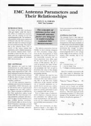
SHIELDING EFFECTIVENESS IN dB<br />
120<br />
100<br />
80<br />
60<br />
40<br />
20<br />
Typical Shielding Effectiveness 3/16” and 1/8” Cell<br />
STEEL<br />
10 KHz<br />
BRASS<br />
MAGNETIC<br />
100 KHz<br />
ELECTRIC<br />
1 MHz<br />
10 MHz<br />
100 MHz<br />
FREQUENCY<br />
PLANEWAVE<br />
1 GHz<br />
<strong>EMI</strong>/<strong>RFI</strong> <strong>Shielded</strong><br />
<strong>Waveguide</strong> <strong>Air</strong> <strong>Vents</strong><br />
Steel Honeycomb- 3/16"<br />
Magnetic Electric Planewave Microwave<br />
1 KHz 20 KHz 100 KHz 10 MHz 100 MHz 1 GHz 10 GHz 18GHz<br />
25 dB 120 dB 120 dB 120 dB 120 dB 120 dB 120 dB 120dB<br />
Steel Honeycomb- 1/8"<br />
Magnetic Electric Planewave Microwave<br />
1 KHz 20 KHz 100 KHz 10 MHz 100 MHz 1 GHz 10 GHz 18GHz 40 GHz*<br />
25 dB 120 dB 120 dB 120 dB 120 dB 120 dB 120 dB 120 dB 100 dB<br />
Brass Honeycomb<br />
Magnetic Electric Planewave<br />
1 KHz 20 KHz 100 KHz 10 MHz 100 MHz 1 GHz<br />
25 dB 70 dB 120 dB 120 dB 120 dB 120 dB<br />
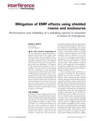
The Maximum Static Pressure Drop<br />
3/16" Hex Cell:<br />
Inches of Water: 0.015 0.025 0.042 0.065<br />
At Feet per Minute: 400 600 800 1,000<br />
1/8" Hex Cell:<br />
Inches of Water: 0.025 0.035 0.045 0.060<br />
At Feet per Minute: 400 600 800 1,000<br />
*For applications above 40 GHz a supplemental RF Labyrinth can be provided<br />
3/16”<br />
18 GHz<br />
10 GHz<br />
PRESSURE DROP (INCHES OF WATER)<br />
MICROWAVE<br />
1/8”<br />
Typical Pressure Drop 3/16” and 1/8” Cell<br />
1.000<br />
0.100<br />
0.010<br />
0.001<br />
40 GHz*<br />
400<br />
1200<br />
2000<br />
VELOCITY* (FEET PER MINUTE)<br />
*Multiply by area to obtain CFM.<br />
Phone +1.630.307.7200 • info@ets-lindgren.com • www.ets-lindgren.com<br />
Offices in the US, Finland, UK, France, Singapore, Japan, China, Taiwan<br />
A properly designed waveguidebeyond-cutoff<br />
opening will act like a<br />
high-pass filter. The cutoff frequency<br />
is a function of the cross-section<br />
of the waveguide. For a cylindrical<br />
waveguide, the cutoff frequency of the<br />
dominant TE mode is:<br />
fc = 6.92/d GHz<br />
The cutoff frequency <strong>for</strong> the TE mode<br />
of rectangular waveguides is:<br />
fc = 5.90/b GHz<br />
In these equations,<br />
fc = cutoff frequency <strong>for</strong> the<br />
dominant mode in gigahertz<br />
d = inside diameter of a cylindrical<br />
waveguide in inches<br />
b = greatest dimension of rectangular<br />
waveguide in inches<br />
In<strong>for</strong>mation presented is subject to change as product improvements are made. Contact the <strong>ETS</strong>-<strong>Lindgren</strong> Sales Department <strong>for</strong> current specifications. 11/08 500 BL © 2008 <strong>ETS</strong>-<strong>Lindgren</strong> REV C<br />
1/8”<br />
3/16”