Hotsy 965SS-1075SSE 97-6554 0605 - ETS Company Pressure ...
Hotsy 965SS-1075SSE 97-6554 0605 - ETS Company Pressure ...
Hotsy 965SS-1075SSE 97-6554 0605 - ETS Company Pressure ...

Create successful ePaper yourself
Turn your PDF publications into a flip-book with our unique Google optimized e-Paper software.
listed<br />
®<br />
serial number:<br />
date purchased:<br />
for sales and service, please contact:<br />
models 965ss, 1065ss,<br />
1065sse, 1075sse<br />
OPERATING INSTRUCTIONS AND PARTS MANUAL<br />
Thank you for purchasing a <strong>Hotsy</strong> <strong>Pressure</strong> Washer. This manual covers the operation and maintenance<br />
of your pressure washer. All information in this manual is based on the latest product information<br />
available at the time of printing. <strong>Hotsy</strong>, Inc. reserves the right to make changes at any time<br />
without incurring any obligation.<br />
Read instructions carefully before attempting to assemble, install, operate or service this pressure<br />
washer. Failure to comply with instructions could result in personal injury and/or property damage!<br />
c<br />
<strong>97</strong>-<strong>6554</strong><br />
®
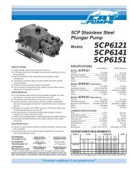
965ss specifications<br />
1065sse specifications<br />
Pump Volume At Pump Head: 3.0 GPM/180 GPH Pump Volume At Pump Head: 3.5 GPM/210 GPH<br />
Pump <strong>Pressure</strong> At Pump Head: 3000 PSI<br />
Pump <strong>Pressure</strong> At Pump Head: 3000 PSI<br />
Burner Type: Fuel Oil Fired, 248,000 BTU/Hr.<br />
Burner Type: Fuel Oil Fired, 310,000 BTU/Hr.<br />
Burner Fuel <strong>Pressure</strong>: 140 PSI<br />
Burner Fuel <strong>Pressure</strong>: 160 PSI<br />
Machine Power Rating: 9 HP Honda<br />
Machine Power Rating: 11 HP Honda Electric Start<br />
Machine Weight: 385 Lbs.<br />
Machine Weight: 450 Lbs.<br />
Shipping Weight: 415 Lbs.<br />
Shipping Weight: 480 Lbs.<br />
Exhaust Stack Size: 8"<br />
Exhaust Stack Size: 8"<br />
Machine Dimensions: Length=47", Width=31", Height=49" Machine Dimensions: Length=47", Width=31", Height=49"<br />
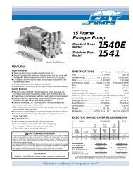
1065ss specifications 1075sse specifications<br />
Pump Volume At Pump Head: 3.5 GPM/210 GPH Pump Volume At Pump Head: 3.8 GPM/228 GPH<br />
Pump <strong>Pressure</strong> At Pump Head: 3000 PSI<br />
Pump <strong>Pressure</strong> At Pump Head: 3500 PSI<br />
Burner Type: Fuel Oil Fired, 310,000 BTU/Hr.<br />
Burner Type: Fuel Oil Fired, 310,000 BTU/Hr.<br />
Burner Fuel <strong>Pressure</strong>: 160 PSI<br />
Burner Fuel <strong>Pressure</strong>: 160 PSI<br />
Machine Power Rating: 11 HP Honda<br />
Machine Power Rating: 13 HP Honda Electric Start<br />
Machine Weight: 450 Lbs.<br />
Machine Weight: 450 Lbs.<br />
Shipping Weight: 480 Lbs.<br />
Shipping Weight: 480 Lbs.<br />
Exhaust Stack Size: 8"<br />
Exhaust Stack Size: 8"<br />
Machine Dimensions: Length=47", Width=31", Height=49" Machine Dimensions: Length=47", Width=31", Height=49"
Important Safety Information 4-5<br />
Component Identification 6<br />
Assembly Instructions 7-8<br />
Installation Instructions 8-9<br />
Operation Instructions 10-11<br />
General Cleaning Techniques & Storage 12<br />
Maintenance 13<br />
Troubleshooting 14-15<br />
Exploded Views & Parts List 16-19<br />
Control Panel Assembly & Parts List 20<br />
Burner Assembly & Parts List 21<br />
Fuel Tank Assembly & Parts List 22<br />
Pump Assembly & Parts List - <strong>965SS</strong> 23<br />
Pump Assembly & Parts List, 1065SS, 1065SSE, <strong>1075SSE</strong> 24-25<br />
Coil Outlet Assembly & Parts List, <strong>965SS</strong> 26<br />
Coil Inlet Assembly & Parts List, 1065SS, 1065SSE 27<br />
Coil Inlet Assembly & Parts List, <strong>1075SSE</strong> 28<br />
Coil Inlet Parts Exploded View and Parts List 29<br />
Hose, Spray Gun & Wand Assembly & Parts List 30<br />
Unloader Exploded View and Parts List 31<br />
HS Pump Exploded View and Parts List 32-33<br />
HG-1 Pump Exploded View and Parts List 34-35<br />
Wiring Diagrams 36-37<br />
Warranty<br />
Model Number ______________________________<br />
Serial Number ______________________________<br />
Date of Purchase ___________________________<br />
The model and serial numbers will be found on a decal attached<br />
to the pressure washer. You should record both serial number and<br />
date of purchase and keep in a safe place for future reference.<br />
<strong>97</strong>-<strong>6554</strong> • HOTSY <strong>965SS</strong>-1075SS • REV. 5/06<br />
contents<br />
3
OPERATOR’S MANUAL PRESSURE WASHER<br />
4<br />
Warning<br />
read operator’s<br />
manual<br />
thoroughly<br />
prior to use.<br />
CAUTION: To reduce the risk of<br />
injury, read operating instructions<br />
carefully before using.<br />
1. Read owner's manual thoroughly.<br />
Failure to follow instructions<br />
could cause malfunction of<br />
the machine and result in death,<br />
serious bodily injury and/or property<br />
damage.<br />
2. Know how to stop machine and bleed pressures<br />
quickly. Be thoroughly familiar with the controls.<br />
3. Stay alert — watch what you are doing.<br />
important safety information<br />
4. All installations must comply with local codes.<br />
Contact your electrician, plumber, utility company<br />
or the selling distributor for specific details.<br />
WARNING: Risk of asphyxiation.<br />
Warning<br />
Use this product only in a well<br />
ventilated area.<br />
risk of<br />
asphyxiation.<br />
use only in a Well<br />
ventilated area.<br />
Warning<br />
risk of fire.<br />
do not add fuel<br />
When operating<br />
machine.<br />
Warning<br />
keep Water spray<br />
aWay from<br />
electrical Wiring.<br />
5. When the machine is working,<br />
do not cover or place in<br />
a closed space where ventilation<br />
is not sufficient.<br />
WARNING: Risk of fire. Do not<br />
add fuel when the machine in<br />
operating.<br />
6. Risk of explosion — do not<br />
spray flammable liquids or<br />
operate in an explosive location.<br />
Operate only where<br />
open flame or torch is permitted.<br />
WARNING: Keep water spray<br />
away from electrical wiring<br />
or fatal electrical shock may<br />
result.<br />
7. To protect the operator from<br />
electrical shock, the machine<br />
must be electrically grounded. It<br />
is the responsibility of the owner<br />
to connect this machine to a UL<br />
grounded receptacle of proper<br />
voltage and amperage ratings. Do not spray water<br />
on or near electrical components. Do not touch<br />
machine with wet hands or while standing in water.<br />
Always disconnect power before servicing.<br />
8. Grip cleaning wand securely with both hands before<br />
starting the cleaner. Failure to do this could<br />
result in injury from a whipping wand.<br />
Warning<br />
high pressure<br />
spray can pierce<br />
skin and tissues.<br />
WARNING: High pressure<br />
stream of fluid that this equipment<br />
can produce can pierce<br />
skin and its underlying tissues,<br />
leading to serious injury and<br />
possible amputation.<br />
9. High pressure developed by<br />
these machines can cause<br />
personal injury or equipment<br />
damage. Use caution when<br />
operating. Do not direct discharge stream at<br />
people, or severe injury and/or death may result.<br />
10. Never make adjustments on machine while<br />
in operation; disconnect from electrical source or<br />
shut off gas valve.<br />
WARNING: High pressure spray<br />
Warning<br />
can cause paint chips or other<br />
particles to become airborne<br />
and fly at high speeds.<br />
protective eyeWear<br />
and clothing must<br />
be Worn.<br />
Warning<br />
risk of injury.<br />
hot surfaces<br />
can cause burns<br />
11. Eye safety devices and foot<br />
protection must be worn<br />
when using this equipment.<br />
WARNING: Risk of injury. Hot<br />
surfaces can cause burns. Use<br />
only designated gripping areas<br />
of spray gun and wand. Do not<br />
place hands or feet on non-insulated<br />
areas of the pressure<br />
washer when starting gasoline<br />
engine.<br />
12. Machines with shut-off trigger gun should not be<br />
operated with the trigger in the off position for extensive<br />
periods of time as this may cause damage<br />
to the pump.<br />
13. Protect from freezing.<br />
14. Be certain all quick coupler fittings are secured<br />
before using pressure washer.<br />
15. Do not allow acids, caustic, or abrasive fluids to<br />
pass through the pump.<br />
16. Inlet water must be from a cold, fresh city water<br />
supply.<br />
17. To reduce the risk of injury, close supervision is<br />
necessary when a machine is used near children.<br />
Do not allow children to operate the pressure<br />
washer. this machine must be attended during<br />
operation.<br />
1 8. The best insurance against an accident is precaution<br />
and knowledge of the machine.<br />
19. Do not operate this product when fatigued or under<br />
the influence of alcohol or drugs. Keep operating<br />
area clear of all persons.<br />
<strong>97</strong>-<strong>6554</strong> • HOTSY <strong>965SS</strong>-1075SS • REV. 5/06
important safety information<br />
20. <strong>Hotsy</strong> will not be liable for any changes made to<br />
our standard machines, or any components not<br />
purchased from <strong>Hotsy</strong>.<br />
21. Do not overreach or stand on unstable support.<br />
Keep good footing and balance at all times.<br />
22. Follow maintenance instructions specified in manual.<br />
23. Cleaning area should be provided with adequate<br />
slopes and drainage to reduce possibility of falls<br />
because of slippery surfaces.<br />
24. Turn burner off and cool to 100°F before turning<br />
machine off.<br />
2 5. Use extreme caution when moving pressure<br />
washer over rough or uneven surfaces.<br />
2 6. When applying detergents follow the safety rules<br />
on the detergent label. Use detergent from a covered<br />
D.O.T. approved container.<br />
2 7. This machine has been provided with Warning and<br />
Instruction decals for the safety of the operator. If<br />
these decals are removed or become damaged<br />
they should be replaced. Contact your dealer for<br />
replacement decals.<br />
<strong>97</strong>-<strong>6554</strong> • HOTSY <strong>965SS</strong>-1075SS • REV. 5/06<br />
PRESSURE WASHER OPERATOR’S MANUAL<br />
5
OPERATOR’S MANUAL PRESSURE WASHER<br />
6<br />
unloader<br />
valve<br />
pump<br />
detergent<br />
injector<br />
pump — Delivers a specific gpm to the high pressure<br />
nozzle which develops pressure.<br />
spray gun — Controls the application of water and<br />
detergent onto cleaning surface with trigger device.<br />
Includes safety latch.<br />
detergent injector — Allows you to siphon and mix<br />
detergents.<br />
Wand — Must be connected to the spray gun.<br />
high pressure hose — Connect one end to water<br />
pump high pressure discharge nipple and the other<br />
end to spray gun.<br />
component identification<br />
coil outlet<br />
burner<br />
fuel oil<br />
tank<br />
spray<br />
gun<br />
burner<br />
exhaust<br />
<strong>97</strong>-<strong>6554</strong> • HOTSY <strong>965SS</strong>-1075SS • REV. 5/06<br />
hose<br />
hanger<br />
Wand<br />
engine<br />
high<br />
pressure<br />
nozzle<br />
high<br />
pressure hose<br />
unloadervalve — Safety device which, when the spray<br />
gun closes, redirects flow of water. (Not Shown.)<br />
note: if trigger on spray gun is released for more<br />
than 2 minutes, water may leak from the pump<br />
protector. Warm water will discharge from pump<br />
protector onto floor.this system prevents internal<br />
pump damage.
unpacking<br />
Unpack carefully. Wear safety glasses or goggles while<br />
unpacking, assembling, or operating pressure washer.<br />
If there are missing components or hidden damage,<br />
immediately contact carrier concerning discrepancies.<br />
1. Cut strapping band from pressure washer and pallet.<br />
2. Remove pressure washer from pallet.<br />
parts included<br />
• <strong>Pressure</strong> Washer<br />
• <strong>Pressure</strong> Hose<br />
• Wand<br />
• Operating Instructions and Parts Manual<br />
• Gasoline Engine Manual<br />
• Parts Bag Containing:<br />
<strong>Pressure</strong> Nozzles (3 Ea.)<br />
Trigger Gun<br />
Battery Terminals (2 Ea.)<br />
tools required<br />
• 8" Adjustable Wrench<br />
• Teflon Tape<br />
• Flat Blade Screwdriver<br />
pressure hose, trigger gun and Wand<br />
1. When assembling, use teflon tape on all threaded<br />
plumbing connections to prevent leakage.<br />
2. Install the pressure hose on the pressure washer as<br />
shown in figure 1.<br />
relief valve<br />
pressure hose<br />
Figure 1 - <strong>Pressure</strong> Hose Installation<br />
assembly instructions<br />
coil outlet<br />
<strong>97</strong>-<strong>6554</strong> • HOTSY <strong>965SS</strong>-1075SS • REV. 5/06<br />
3. Assemble wand components as shown in figure 2.<br />
Quick disconnect<br />
Figure 2 - Wand Assembly<br />
NOTE: The pressure nozzle is not to be installed at<br />
this time.<br />
4. Make sure all plumbing connections are tight.<br />
battery<br />
Wand<br />
Quick<br />
disconnect plug<br />
pressure<br />
hose<br />
Quick<br />
disconnect<br />
trigger gun<br />
WARNING: Wear eye, hand and skin protection when<br />
handling or connecting battery.<br />
WARNING: Batteries generate explosive gases during<br />
normal battery operation.<br />
WARNING: DO NOT expose the battery to flame or<br />
sparks as these gases may ignite.<br />
WARNING: Battery fluid is highly acidic. If battery fluid<br />
contacts skin or clothing, wash immediately with soap<br />
and water. If battery fluid enters eye, immediately flood<br />
eye with running cold water for at least 15 minutes<br />
and get immediate medical attention.<br />
1. electric start machines only: Place battery in battery<br />
box (battery not included). Use a standard 12 volt<br />
automotive battery. Select a battery similar to the one<br />
in figure 3 for proper fit and installation.<br />
8-3/4"<br />
max<br />
Figure 3 - Battery Dimensions<br />
10-1/2"<br />
max<br />
6-3/4"<br />
max<br />
PRESSURE WASHER OPERATOR’S MANUAL<br />
7
OPERATOR’S MANUAL PRESSURE WASHER<br />
8<br />
battery<br />
terminal<br />
12 volt<br />
battery<br />
battery box<br />
assembly & installation instructions<br />
2. Install the provided battery terminals as shown in<br />
figure 4.<br />
box strap<br />
battery<br />
box lid<br />
Figure 4 - Battery Installations/Connections<br />
responsibility<br />
installation<br />
black Wire from<br />
control box<br />
black Wire<br />
from voltage<br />
regulator<br />
red Wire from<br />
control box<br />
red Wire from<br />
voltage regulator<br />
3. To reduce the possibility of sparking attach the wires<br />
to the battery in the following order. Refer to figure<br />
4. First attach the red wire from the voltage regulator<br />
and the red wire from the control box to the positive<br />
“+” terminal of battery. Next, attach the black wire<br />
from the voltage regulator and the black wire from the<br />
control box to the negative “-” terminal of the battery.<br />
To disconnect the battery remove the wires in the<br />
opposite order as installed. Install battery box cover<br />
and fasten in place.<br />
The owner and/or user must have an understanding of<br />
the manufacturer’s operating instructions and warnings<br />
before using this <strong>Hotsy</strong> pressure washer. Warning information<br />
should be emphasized and understood. If the<br />
operator is not fluent in English, the manufacturer’s instructions<br />
and warnings shall be read to and discussed<br />
with the operator in the operator’s native language by<br />
the purchaser/owner, making sure that the operator<br />
comprehends its contents.<br />
Owner and/or user must study and maintain for future<br />
reference the manufacturers’ instructions.<br />
This manual should be considered a permanent part<br />
of the machine and should remain with it if machine<br />
is resold.<br />
When ordering parts, please specify model and serial<br />
number.<br />
getting started<br />
<strong>97</strong>-<strong>6554</strong> • HOTSY <strong>965SS</strong>-1075SS • REV. 5/06<br />
IMPORTANT: Proper initial installation of equipment<br />
will assure more satisfactory performance, longer<br />
service life, and lower maintenance cost.<br />
IMPORTANT: The use of a backflow preventer on<br />
the water supply hose is recommended and may be<br />
required by local code.<br />
The pressure washer should be run on a level surface<br />
and in a protected area where it is not readily influenced<br />
by outside forces such as strong winds, freezing<br />
temperatures, rain, etc. The pressure washer should<br />
be located to assure easy access for filling of fluids,<br />
adjustments and maintenance. Normal precautions<br />
should be taken by the operator to prevent moisture<br />
from reaching the pressure washer. It is recommended<br />
that a partition be made between the wash area and the<br />
pressure washer to prevent direct spray from the wand<br />
from coming in contact with the pressure washer. Moisture<br />
reaching the equipment will reduce the pressure washer’s<br />
service life. All installations must comply with the local<br />
codes covering such installations.<br />
venting<br />
CAUTION: All venting must be in accordance with applicable<br />
federal and state laws, and local ordinances.<br />
Consult local heating contractors.<br />
If the pressure washer is to be used in an enclosed area,<br />
a flue must be installed to vent burner and engine exhaust<br />
to the outside atmosphere. Be sure the flue is the same<br />
size as the burner exhaust vent on the pressure washer.<br />
See component identification for location. Poor draft<br />
will cause the pressure washer to soot and not operate<br />
properly. When selecting the location for installation,<br />
beware of poorly ventilated locations or areas where<br />
exhaust fans may cause an insufficient supply of oxygen.<br />
Proper combustion can only be obtained when there is a<br />
sufficient supply of oxygen available for the amount of fuel<br />
being burned. If it is necessary to install the machine in a<br />
poorly ventilated area, outside fresh air may have to be<br />
piped to the burner and a fan installed to bring sufficient<br />
air into the machine. Locate the pressure washer so<br />
that the flue will be as straight as possible and protrude<br />
through the roof at a proper height and location to provide<br />
adequate draft. This oil fired pressure washer must have<br />
a draft regulator installed in the flue (available from most<br />
heating contractors). A draft regulator will permit proper<br />
upward flow of exhaust flue gases.<br />
In addition, the pressure washer should never be operated<br />
in an enclosed area where high ambient temperatures<br />
exist. High ambient temperatures (above 100 o F) can<br />
cause engine oil failure and will greatly reduce the<br />
engine’s performance.
gasoline engine<br />
The gasoline engine is preset for operation at altitudes<br />
below 3000 feet above sea level. If operated at higher<br />
altitudes, it may be necessary to install a high altitude<br />
main jet in the carburetor. Contact an authorized engine<br />
sales and service center for details.<br />
pre-operation check<br />
Pump Oil (SAE 30W non-detergent oil)<br />
Cold Water Supply (6 gpm • 5/8" • 20 psi)<br />
Hose, wand, nozzle (nozzle size per serial plate)<br />
Water filter (intact, nonrestrictive)<br />
Engine fuel (unleaded 86 or higher)<br />
Engine oil (SAE 10W30)<br />
Burner fuel (No. 1 or No. 2 home heating fuel or diesel)<br />
oil burner<br />
burner air adjustment: The oil burner on this machine<br />
is preset for operation at altitudes below 3000 feet. If<br />
operated at higher altitudes, it may be necessary to adjust<br />
the air shutter and air band setting. Adjust the air shutter<br />
for a #1 or #2 smoke spot on the Bacharach scale.<br />
To adjust, start machine and turn burner ON (refer<br />
to operation for details). Loosen two locking screws<br />
found in the air shutter openings (refer to Figure 5) and<br />
close air shutter until black smoke appears from burner<br />
exhaust vent. Note air shutter position. Next, slowly open<br />
the air shutter until white smoke just starts to appear.<br />
Turn air shutter halfway back to the black smoke position<br />
previously noted. Tighten locking screws.<br />
air band<br />
Figure 5 - Burner Adjustment<br />
installation instructions<br />
fuel<br />
filter<br />
pressure<br />
adjustment screw<br />
<strong>97</strong>-<strong>6554</strong> • HOTSY <strong>965SS</strong>-1075SS • REV. 5/06<br />
If the desired position cannot be obtained using only the<br />
air shutter, lock the air shutter in as close a position as<br />
can be obtained, then repeat the above procedure on the<br />
air band setting.<br />
CAUTION: If white smoke appears from burner<br />
exhaust vent during start-up or operation, discontinue<br />
use and readjust air bands.<br />
NOTE: If a flue is installed, have a professional serviceman<br />
adjust your burner for a #1 or #2 smoke spot<br />
on the Bacharach scale.<br />
PRESSURE WASHER OPERATOR’S MANUAL<br />
9
OPERATOR’S MANUAL PRESSURE WASHER<br />
10<br />
before starting<br />
1. Read all manuals provided with this pressure washer.<br />
Become familiar with location and function of all<br />
operating and safety controls.<br />
WARNING: Check hoses, fittings, wand, trigger gun<br />
and fuel connections daily for signs of wear, cracks<br />
and looseness, and replace as required.<br />
2. Connect water supply hose to the garden hose connector<br />
located on pump. The water faucet and supply<br />
hose must be capable of providing a minimum of 3.5<br />
gallons per minute (GPM).<br />
3. Fill oil burner fuel tank. Use kerosene, #1 grade home<br />
heating oil, #1 or #2 diesel fuel. do not use gasoline,<br />
crankcase oil drainings, or Waste<br />
oil.<br />
WARNING: DO NOT fill engine fuel tank while engine<br />
is running or hot. Let engine cool before refueling or<br />
spontaneous fire may result. Fuel spillage or vapors<br />
could ignite if engine is hot.<br />
4. Fill the engine fuel tank. Do not overfill, fill to the<br />
bottom of filler neck only. Use lead free gasoline minimum<br />
86 octane. do not use gasoline containing<br />
more than 15% MTBE, 5% methanol or 10% ethanol.<br />
Refer to the provided gasoline engine manual for<br />
additional details.<br />
5. Check pump and engine oil levels.<br />
6. If detergents are to be used, only use detergents<br />
intended for pressure washers. Follow instructions on<br />
the detergent container.<br />
IMPORTANT: Before installing pressure nozzle on<br />
initial start-up, turn on the water supply and allow<br />
water to run from the end of the wand until clear to<br />
prevent the pressure nozzle from clogging.<br />
IMPORTANT: If the pressure washer has not been<br />
used for an extended period of time, remove the<br />
pressure nozzle from the end of the wand and turn<br />
on water supply. Allow water to run from the end of<br />
the wand until clear.<br />
7. Install the proper pressure nozzle for your cleaning<br />
needs on the end of wand, refer to figure 6.<br />
manual<br />
trigger lock<br />
operation instructions<br />
pressure<br />
nozzle<br />
Figure 6 - Nozzle Installation/Manual Trigger Lock<br />
<strong>97</strong>-<strong>6554</strong> • HOTSY <strong>965SS</strong>-1075SS • REV. 5/06<br />
IMPORTANT: The trigger gun provided with this pressure<br />
washer is equipped with a manual trigger lock to<br />
prevent accidental operation of the trigger gun. (Refer<br />
to Figure 6.) The manual trigger lock should be used<br />
whenever the trigger gun is not in use.<br />
to start<br />
IMPORTANT: The water must be turned on before<br />
starting. Running the pump dry will cause damage<br />
and void warranty.<br />
IMPORTANT: DO NOT allow the machine to run with<br />
trigger of the trigger gun released for more than<br />
2 minutes at any one time or damage to pump may<br />
occur.<br />
1. Turn ON water supply.<br />
2. Hold wand firmly, release trigger of trigger gun.<br />
3. Place engine ON/OFF switch in the ON position.<br />
4. Open fuel shutoff valve (if so equipped). Move choke<br />
lever to FULL CHOKE position, (choke may not be<br />
needed on warm engine). Move throttle lever to HALF<br />
THROTTLE position.<br />
5. Pull the rope starter slowly until resistance is felt, then<br />
pull briskly. Do not allow the rope starter to snap back<br />
against the engine. Return it gently to prevent damage<br />
to the starter.<br />
6. When the engine starts, move choke lever until<br />
engine runs smoothly. When engine warms, move<br />
choke lever to NO CHOKE position. Move throttle<br />
lever to FULL THROTTLE position.<br />
IMPORTANT: To allow for proper battery charging,<br />
the throttle control must be kept in the full throttle<br />
position during operation.<br />
NOTE: If engine fails to start, refer to Troubleshooting<br />
Guide in this manual.<br />
7. Squeeze trigger of trigger gun and allow air to purge<br />
from system.<br />
8. If hot water is desired, adjust the thermostat to the<br />
proper temperature and turn burner switch ON. The<br />
burner will light immediately with a small puff of smoke.<br />
You may need to initially adjust your burner for peak<br />
performance. See oil burner section under installation.<br />
When the trigger of the trigger gun is released<br />
or when the thermostat temperature setting is reached,<br />
the burner will automatically turn off.<br />
to clean<br />
The detergent injector valve operates by reducing the<br />
volume of water, thus a vacuum is achieved and detergent<br />
is drawn into the system. do not reduce the water inlet<br />
flow so the pump cavitates due to water starvation.<br />
Operating a pump with insufficient water will damage<br />
the pump seals.<br />
1. Insert detergent inlet line into container of mixed<br />
detergent.
2. Completely open detergent control knob located<br />
on the side of the detergent injector valve. Refer to<br />
figure 7.<br />
detergent on<br />
(counterclockwise)<br />
detergent<br />
control knob<br />
Figure 7 - Detergent Injector Valve<br />
3. Start the detergent suction by rotating the water<br />
adjustment knob of the detergent injector valve.<br />
Refer to figure 7. Turning the knob counterclockwise<br />
will pull detergent into the system. The flow may be<br />
observed through the clear detergent line. Secure the<br />
knob position with the knurled nut.<br />
4. The side detergent control knob can now be adjusted<br />
to meter the desired amount of detergent.<br />
5. Wash from the bottom to the top, using side to side<br />
motions. This washes away heavy dirt and allows the<br />
detergent to soak as you work toward the top.<br />
6. Do not wash at a 90 o angle to the work (straight at<br />
it). This will allow water to splash back at you and<br />
reduces your cleaning power. Wash at a 30 o to 60 o<br />
angle to the work. This will allow the water to splash<br />
away from you and the water will wash the dirt away<br />
faster and easier.<br />
operation instructions<br />
detergent<br />
injector<br />
Water<br />
adjustment<br />
knob<br />
<strong>97</strong>-<strong>6554</strong> • HOTSY <strong>965SS</strong>-1075SS • REV. 5/06<br />
7. Use the width of the spray pattern to wash in a<br />
wide path. Overlap spray paths for complete coverage<br />
washing from side to side, using slow, steady<br />
motions.<br />
8. The nozzle should be 12" to 24" from work, closer<br />
for tough areas. Be careful on painted or delicate<br />
surfaces, the pressure may damage surface if nozzle<br />
is too close.<br />
9. Small parts should be washed in a basket so the<br />
pressure does not push them away. Larger, lightweight<br />
parts should be clamped down so the pressure does<br />
not push them away.<br />
10. Turn the side detergent control knob clockwise (CW)<br />
for detergent decrease. Wait for detergent to clear.<br />
Always rinse with cold water after using detergent.<br />
Rinse from the top to the bottom to prevent detergent<br />
from dripping onto a rinsed area. For the best results,<br />
contact your <strong>Hotsy</strong> dealer to help you select the best<br />
detergent for your application.<br />
to stop<br />
1. If detergents were used, draw clear water through the<br />
detergent inlet line to purge detergent. Failure to do<br />
so may clog detergent injector valve.<br />
2. If burner was used, turn OFF burner switch and<br />
allow pump to run cold water through coil for several<br />
minutes.<br />
3. Move throttle lever to idle position.<br />
4. Turn engine ON/OFF switch to the OFF position.<br />
5. Close fuel shutoff valve (if so equipped).<br />
6. Turn water supply OFF.<br />
7. Squeeze trigger of trigger gun to relieve system<br />
pressure.<br />
PRESSURE WASHER OPERATOR’S MANUAL<br />
11
OPERATOR’S MANUAL PRESSURE WASHER<br />
12<br />
general cleaning techniQues & storage<br />
cleaning techniQues<br />
Pre-rinse cleaning surface with fresh water. Place detergent<br />
suction tube directly into cleaning solution and apply<br />
to surface at low pressure (for best results, limit your work<br />
area to sections approximately 6 feet square and always<br />
apply detergent from bottom to top). Allow detergent to<br />
remain on surface 1-3 minutes. Do not allow detergent<br />
to dry on surface. If surface appears to be drying, simply<br />
wet down surface with fresh water. If needed, use brush<br />
to remove stubborn dirt. Rinse at high pressure from top<br />
to bottom in an even sweeping motion keeping the spray<br />
nozzle approximately 1 foot from cleaning surface. Use<br />
overlapping strokes as you clean and rinse any surface.<br />
For best surface cleaning action spray at a slight angle.<br />
recommendations:<br />
• Before cleaning any surface, an inconspicuous<br />
area should be cleaned to test spray pattern and<br />
distance for maximum cleaning results.<br />
• If painted surfaces are peeling or chipping, use<br />
extreme caution as pressure washer may remove<br />
the loose paint from the surface.<br />
• Keep the spray nozzle a safe distance from the<br />
surface you plan to clean. High pressure wash a<br />
small area, then check the surface for damage. If no<br />
damage is found, continue to pressure washing.<br />
CAUTION - Never use:<br />
• Bleach, chlorine products and other corrosive<br />
chemicals<br />
• Liquids containing solvents (i.e., paint thinner,<br />
gasoline, oils)<br />
• Tri-sodium phosphate products<br />
• Ammonia products<br />
• Acid-based products<br />
These chemicals will harm the machine and will damage<br />
the surface being cleaned.<br />
rinsing<br />
It will take a few seconds for the detergent to clear. Apply<br />
safety latch to spray gun. Select and install desired high<br />
pressure nozzle. note: You can also stop detergent from<br />
flowing by removing detergent siphon tube from bottle.<br />
storage<br />
DANGER: DO NOT store flammable liquids (gasoline,<br />
diesel fuel, solvents, etc.) near pressure washer, or in<br />
non-ventilated areas.<br />
Protect from freezing by storing in a heated area, or by<br />
flushing the system with antifreeze (use an automotive<br />
engine antifreeze or windshield washer solvent to<br />
antifreeze). To flush the system with antifreeze, the<br />
following steps are to be followed:<br />
1. Connect the water supply hose to the garden<br />
hose connector located on the pump. Turn on water<br />
supply.<br />
2. Place the detergent inlet line into a container of<br />
<strong>97</strong>-<strong>6554</strong> • HOTSY <strong>965SS</strong>-1075SS • REV. 5/06<br />
antifreeze.<br />
3. Hold wand firmly, release trigger of trigger gun.<br />
4. Start engine. Place throttle lever in Full Throttle<br />
position.<br />
5. Squeeze trigger of trigger gun and allow water to<br />
flow from the end of the wand. Watch for antifreeze<br />
to be drawn through the detergent inlet line. Allow<br />
the antifreeze to be drawn into the system for 5 to<br />
10 seconds.<br />
6. Release the trigger of the trigger gun and stop<br />
engine.<br />
7. Turn off water supply and disconnect water supply<br />
hose from the pump.<br />
8. Attach a short length of hose (approximately 3 feet<br />
long) to the garden hose connector located on the<br />
pump. Install a funnel in the other end of the hose as<br />
shown in figure 8.<br />
9. Hold wand firmly, release the trigger of the trigger<br />
gun.<br />
10. Start engine. Place throttle lever in the idle position.<br />
11. Squeeze trigger on trigger gun.<br />
Figure 8 - Winterizing<br />
funnel<br />
garden hose connector<br />
12. Slowly pour antifreeze into the funnel. Continue to<br />
add antifreeze until antifreeze flows from the end of<br />
the wand.<br />
13. Squeeze and release the trigger of the trigger gun<br />
several times to antifreeze the unloader system.<br />
14. Release the trigger of the trigger gun. Stop engine.<br />
15. Squeeze the trigger of the trigger gun to relieve system<br />
pressure.<br />
For added protection, after antifreezing, disconnect the<br />
pressure hose from the machine and remove the coil drain<br />
plug (refer to component identification for location.)<br />
After coil has drained, replace pressure hose and coil<br />
drain plug. If the pressure washer is not to be used for<br />
an extended length of time, it is recommended that the<br />
system be flushed with antifreeze for rust protection.<br />
Refer to the gasoline engine manual for engine storage<br />
information.
WARNING: Unauthorized machine modification or<br />
use of non-approved replacement parts may cause<br />
personal injury and/or property damage and will void<br />
the manufacturer warranty.<br />
pump<br />
Lubrication: To lubricate pump, use 30W non-detergent oil<br />
for pump crankcase. Crankcase must be filled to center of<br />
red dot on oil gauge found on the side of the pump, refer<br />
to figure 9. During the break-in-period, make sure the<br />
oil is changed after the first 40 hours of operation. After<br />
that, replace oil every 3 months or 500 hours of operation,<br />
whichever comes first.<br />
Figure 9 - Pump Lubrication<br />
proper pump care:<br />
do not pump acids.<br />
do not allow pump to run dry.<br />
Winterize if storing in freezing temperatures, refer<br />
to storage for details.<br />
Use a water softener on the water system if known<br />
to be high in mineral content.<br />
Use only high quality detergents and follow manufacturer's<br />
mix recommendations.<br />
Flush the system with clear water immediately<br />
after using detergent solutions.<br />
Clean filter screen on detergent inlet line<br />
periodically.<br />
Flush the pressure washer system with antifreeze<br />
if storing for an extended period of time, refer to<br />
storage for details.<br />
gasoline engine<br />
oil fill/dipstick<br />
Refer to the provided gasoline engine manual for<br />
recommended maintenance.<br />
maintenance<br />
oil sight<br />
glass<br />
oil drain<br />
plug<br />
oil burner<br />
<strong>97</strong>-<strong>6554</strong> • HOTSY <strong>965SS</strong>-1075SS • REV. 5/06<br />
blower motor: Inspect the motor brushes for wear every<br />
250 hours of operation and replace when 1/8" to 1/4"<br />
brush material remains. do not allow the brushes to<br />
wear out completely or motor damage will occur. Refer to<br />
burner assembly. The motor bearings are permanently<br />
lubricated and will not require any additional lubrication.<br />
unloader valve<br />
WARNING: The unloader valve on this pressure<br />
washer has been factory set and sealed and is a<br />
field nonadjustable part. Tampering with the factory<br />
setting may cause personal injury and/or property<br />
damage, and will void the manufacturer warranty. For<br />
replacement refer to Pump Assembly.<br />
burner fuel filter<br />
Drain any water which has accumulated in fuel filter<br />
and clean or replace filter element as needed. Refer to<br />
burner assembly.<br />
heating coil<br />
coil descaling: In hard water areas, scale buildup within<br />
the heating coil will occur. Scale deposits will decrease<br />
the water temperature rise and may eventually clog the<br />
heating coil. Contact your local service center when<br />
descaling is needed.<br />
coil desooting: Poor grades of fuel oil or inadequate<br />
combustion air will cause heavy soot buildup on the<br />
outside surface of the heating coil. These deposits will<br />
insulate the coil. This will restrict the air flow through the<br />
coil, further aggravating the soot buildup. Contact your<br />
local service center when desooting is needed.<br />
hour meter<br />
This hour meter will monitor the total hours of operation of<br />
the pressure washer to signal when routine maintenance<br />
is required.<br />
battery<br />
Refer to battery manufacturer’s literature for<br />
recommended maintenance.<br />
PRESSURE WASHER OPERATOR’S MANUAL<br />
13
PRESSURE WASHER Troubleshooting Guide<br />
14<br />
troubleshooting<br />
symptom possible causes corrective action<br />
gas engine Will<br />
not run.<br />
pressure<br />
Washer runs but<br />
Won’t spray.<br />
loW spray<br />
pressure at<br />
pressure<br />
noZZle.<br />
uneven spray<br />
pattern.<br />
pressure<br />
Washer Will not<br />
produce hot<br />
Water.<br />
Out of gas. Replenish supply. Use only recom-mended<br />
fuels. Refer to Before Start-ing under Operation.<br />
Fuel valve closed (if so equipped). Open valve.<br />
Loose spark plug wire. Reconnect.<br />
Choke or throttle set incorrectly. Refer to To Start under Operation.<br />
Engine ON/OFF switch in OFF<br />
position.<br />
<strong>97</strong>-<strong>6554</strong> • HOTSY <strong>965SS</strong>-1075SS • REV. 5/06<br />
Place engine ON/OFF switch in ON position.<br />
Low engine oil level. Replenish supply. Engine will not start or run<br />
if oil is low (on engines equipped with low oil<br />
protection).<br />
Refer to provided gasoline engine manual for additional troubleshooting.<br />
Trigger of trigger gun released. Squeeze trigger.<br />
Water supply not turned on. Open water supply valve.<br />
Clogged pressure nozzle. Clean pressure nozzle opening.<br />
If water spray doesn’t show with in<br />
10-15 seconds<br />
Discontinue running the machine and troubleshoot<br />
as damage to the pump will occur if<br />
allowed to run<br />
Inadequate water supply. Fully open faucet. Check for kinked or damaged<br />
hose. Use 3/4 inch minimum hose. Check<br />
for debris clogging inlet screen.<br />
Partially clogged or damaged pressure<br />
nozzle.<br />
Air being drawn through detergent<br />
inlet line.<br />
Detergent injector valve not set<br />
correctly.<br />
Partially clogged or damaged pressure<br />
nozzle.<br />
Clean or replace.<br />
Refill detergent container. Ensure that pick-up<br />
screen is fully immersed.<br />
Refer to To Clean for settings.<br />
Clean or replace.<br />
Burner switch in OFF position. Place switch in ON position.<br />
Inadequate fuel supply. Refill fuel tank. Use only recommend-ed fuels.<br />
Refer to Before Starting under Operation.<br />
Inadequate water supply. Fully open faucet. Check for kinked or damaged<br />
hose. Use 3/4 inch minimum hose. Check<br />
for debris clogging inlet screen.<br />
Trigger of trigger gun released. Squeeze trigger. Water must be spraying for<br />
burner to light.<br />
Thermostat set too low. Adjust thermostat to desired temp-erature.<br />
Blown fuse. Replace. Fuse is located in control box.<br />
Engine is running too slow. Move throttle lever to full throttle position.
troubleshooting<br />
symptom possible causes corrective action<br />
poor or no<br />
detergent floW.<br />
Inadequate detergent supply. Refill detergent container. Ensure that<br />
pick-up screen is fully immersed. Open<br />
detergent valve.<br />
Detergent screen or hose clogged. Clean. Always start with a clean deter-gent<br />
container.<br />
Detergent injector valve not set<br />
correctly.<br />
Clogged detergent injector check<br />
valve.<br />
poor cleaning. Improper detergent concentration or<br />
mixing.<br />
important<br />
If the pressure washer demonstrates other symptoms or the corrective actions<br />
listed do not correct the problem, contact the local authorized <strong>Hotsy</strong> Service<br />
Center. The <strong>Hotsy</strong> Service Center can be identified by visiting www.hotsy.com or<br />
by calling 1-800-525-1<strong>97</strong>6.<br />
When ordering from your dealer, please provide the following:<br />
model number: 965ss, 1060ss, 1065ss, 1065sse, 1075sse<br />
machine serial number: ________________________________<br />
component part number: ______________________________<br />
description: __________________________________________<br />
<strong>97</strong>-<strong>6554</strong> • HOTSY <strong>965SS</strong>-1075SS • REV. 5/06<br />
Refer to To Clean for settings.<br />
Clean check valve at detergent injector<br />
inlet<br />
Mix detergent per manufacturer’s instructions.<br />
Ensure that powdered detergents are<br />
fully dissolved.<br />
Wrong detergent for the application. Select appropriate detergent.<br />
Rinsing with hot water. A final rinse with cold water will reduce<br />
water spotting.<br />
PRESSURE WASHER Troubleshooting Guide<br />
15
OPERATOR’S MANUAL PRESSURE WASHER<br />
16<br />
1065ss<br />
1065sse<br />
1075sse<br />
for<br />
detail see<br />
fuel tank<br />
assy.<br />
for<br />
detail see<br />
pump<br />
assy.<br />
view a-a<br />
foot brake assy.<br />
(reversed view)<br />
exploded vieW - left side<br />
39<br />
51<br />
18<br />
19<br />
59<br />
53<br />
61<br />
60<br />
54<br />
21<br />
62<br />
52<br />
61<br />
55<br />
23 24<br />
64<br />
63<br />
38<br />
57<br />
<strong>97</strong>-<strong>6554</strong> • HOTSY <strong>965SS</strong>-1075SS • REV. 5/06<br />
22<br />
48<br />
56<br />
46<br />
45
for<br />
detail see<br />
coil inlet<br />
assy.<br />
for<br />
detail see<br />
control<br />
box illus.<br />
20<br />
49<br />
exploded vieW - right side<br />
for<br />
detail see<br />
coil outlet<br />
assy.<br />
25<br />
1<br />
10,11<br />
9<br />
8<br />
2<br />
6<br />
16<br />
68<br />
7<br />
27<br />
44<br />
26<br />
17<br />
47<br />
49<br />
for<br />
detail see<br />
burner<br />
assy.<br />
29<br />
29<br />
58<br />
50<br />
36<br />
13<br />
32<br />
35<br />
<strong>97</strong>-<strong>6554</strong> • HOTSY <strong>965SS</strong>-1075SS • REV. 5/06<br />
3<br />
4<br />
5<br />
28<br />
30<br />
31<br />
15<br />
for<br />
foot brake<br />
detail see<br />
view<br />
a-a<br />
34<br />
14<br />
39<br />
40<br />
43<br />
12<br />
12<br />
39<br />
37<br />
42<br />
43<br />
41<br />
PRESSURE WASHER OPERATOR’S MANUAL<br />
17
OPERATOR’S MANUAL PRESSURE WASHER<br />
18<br />
exploded vieW parts list<br />
item part no. description Qty<br />
1 961532 Tubing 3/8" 38”<br />
2 9.800-049.0 Label, Cleaning Solution 1<br />
3 213044 Burner Exhaust Vent 1<br />
4 268004 Insulation 1<br />
5 860102 Retaining Ring 1<br />
6 780452 Flat Washer 5/16" 6<br />
7 703155 Locknut 5/16" - 18 4<br />
8 646113 Decal Detergent Metering 1<br />
9 834159 Decal <strong>Hotsy</strong> Detergents 1<br />
10 826167 Strain Relief 2<br />
11 703127 Strain Relief Nut 2<br />
12 703185 Locknut 1/4" - 20 (Battery Models Only) 6<br />
13 375292 Mounting Plate (Battery Models Only) 1<br />
14 220119 Battery Box (Battery Models Only) 1<br />
15 890904 Battery Terminal (Battery Models Only) 2<br />
16 834154 Decal Winterize 1<br />
17 10-07993 Decal Warnings 1<br />
18 612984 Bolt 3/8" - 16 x 1" 4<br />
19 780480 Lock Washer 3/8" 4<br />
20 375578 Chassis (1065SS, 1065SSE, <strong>1075SSE</strong>) 1<br />
375575 Chassis (<strong>965SS</strong>) 1<br />
21 232025 Decal Battery 1<br />
22 444462 Decal Caution Gasoline 1<br />
23 646115 Decal Hot Surface 1<br />
24 646026 Decal Carbon Monoxide 1<br />
25 834416 Decal Operating Instruction 1<br />
26 240834 Coil (1065SS, 1065SSE, <strong>1075SSE</strong>) 1<br />
226222 Coil (<strong>965SS</strong>) 1<br />
27 824115 Vent Clip 4<br />
28 375449 Coil Tank (<strong>965SS</strong>) 1<br />
375446 Coil Tank (1065SS,1065SSE,<strong>1075SSE</strong>) 1<br />
29 926598 Rivet 8<br />
30 829<strong>97</strong>9 <strong>Hotsy</strong> Logo Plate 2<br />
31 646095 Decal Troubleshooting 1<br />
32 268013 Insulation (1065SS, 1065SSE, <strong>1075SSE</strong>) 1<br />
268006 Insulation (<strong>965SS</strong> Only) 1<br />
33 213191 Pancake Insulation 1<br />
34 859806 Grommet 1<br />
35 859815 Grommet (Nozzle Holder) 3<br />
36 815329 Snap Bushing 1<br />
37 77-31620-2GS-003 Voltage Reg. (1065SSE,<strong>1075SSE</strong>) 1<br />
860273 Voltage Reg. (<strong>965SS</strong>,1065SS) 1<br />
38 860285 Reducer, M12 to 1/4” Female 1<br />
39 780451 Washer Flat 1/4" 10<br />
40 983013 Wheel 4<br />
<strong>97</strong>-<strong>6554</strong> • HOTSY <strong>965SS</strong>-1075SS • REV. 5/06
exploded vieW parts list<br />
item part no. description Qty<br />
41 817322 Hubcap 4<br />
42 848616 Push Nut 4<br />
43 980254 Flat Washer 5/8" 8<br />
44 815329 Snap Bushing 3<br />
45 661282 Engine 11 HP (1065SS) 1<br />
661254 Engine 9 HP (<strong>965SS</strong>) 1<br />
661364 Engine, E-Start 11 HP (1065SSE) 1<br />
677375 Engine, E-Start 13 HP (<strong>1075SSE</strong>) 1<br />
46 890783 Tag Gasoline Engine 1<br />
47 2-010532 Mount , Vibration, 3/8” Rubber 70 Dura 4<br />
48 612985 Bolt, 3/8” x 1-1/2” NC HH 4<br />
49 703107 Flange Nut 5/16" - 18 8<br />
50 780460 Fender Washer 5/16" 4<br />
51 95-07104827 Lever, Brake 1<br />
52 95-07104829 Linkage, Brake, Red 1<br />
53 95-07101828 Bracket, Brake Pad, red 1<br />
54 90-100472 Bolt, 1/4-20 x 1.0 Plt, Carriage, Zinc 4<br />
55 703185 Nut, 1/4" ESNA, NC 4<br />
56 780562 Washer, 3/8" SAE Flat 4<br />
57 780480 Washer, 3/8" Lock, Split Ring 4<br />
58 9.800-018.0 Label, Tip-Over Hazard 1<br />
59 630980 Cap, Pipe, 1/8" NPT, Brass 1<br />
60 698019 Hose Barb, 1/4" Barb x 1/8" ML Pipe 1<br />
61 823988 Clamp, Hose 2<br />
62 867368 Hose, 1/4" Push-On 3”<br />
63 698020 Hose Barb, 1/4" Barb x 1/4" ML 1<br />
64 921584 Valve, Mini Oil Drain 1<br />
65 823987 Hose Clamp 1<br />
<strong>97</strong>-<strong>6554</strong> • HOTSY <strong>965SS</strong>-1075SS • REV. 5/06<br />
PRESSURE WASHER OPERATOR’S MANUAL<br />
19
OPERATOR’S MANUAL PRESSURE WASHER<br />
20<br />
control panel assembly exploded vieW & parts list<br />
3<br />
5<br />
4<br />
2<br />
6<br />
7<br />
19<br />
1<br />
item part no. description Qty<br />
1 983516 Box, Front 1<br />
2 11-0511 Label, Control Box 1<br />
3 4-050823 Hour Meter, 12-28 V DC 1<br />
4 875465 Switch, Rocker, 15A/12V 1<br />
5 835150 Knob, Thermostat 1<br />
6 735321 Screw, 4mm x 6mm, Pan Head 2<br />
7 915390 Plate, Thermostat Cover 1<br />
8 955940 Thermostat 1<br />
9 707147 Capacitor (<strong>965SS</strong>, 1065SS) 1<br />
10 612937 Bolt, 1/4" x 3/4" 4<br />
11 2-011681 Cap, Capacitor (<strong>965SS</strong>,1065SS) 1<br />
12 703127 Locknut, 1/2" 3<br />
13 615414 Box, Back 1<br />
14 703185 Nut, 1/4" 4<br />
15 876032 Strain Relief 3<br />
16 358026 Clamp (<strong>965SS</strong>,1065SS) 1<br />
17 612945 Bolt, 1/4-20 x 1/2" (<strong>965SS</strong>, 1065SS) 1<br />
18 703106 Nut, 1/4" (<strong>965SS</strong>,1065SS) 1<br />
676638 Fuse, ATC 30 Amp 1<br />
707146 Holder, Fuse 1<br />
829620 Plug 1<br />
19 70-180503 Screw, M4 x 10 4<br />
20 70-030207 Nut, M4 4<br />
Not Shown<br />
10<br />
11<br />
17<br />
<strong>97</strong>-<strong>6554</strong> • HOTSY <strong>965SS</strong>-1075SS • REV. 5/06<br />
8<br />
18<br />
12<br />
16<br />
9<br />
15<br />
14<br />
20<br />
13
urner assembly exploded vieW and parts list<br />
inlet from<br />
fuel tank<br />
1/8”<br />
item part no. description Qty<br />
1 783813 Motor 1<br />
2 661413 Electrode (Pair) 1<br />
3 799429 Nozzle 1<br />
900650 Nozzle (<strong>965SS</strong> Only) 1<br />
4 890742 Ignitor 1<br />
5 723369 Solenoid Valve 1<br />
6 616027 Burner (<strong>965SS</strong>) 1<br />
615856 Burner (1065SS,1065SSE, <strong>1075SSE</strong>) 1<br />
7 830492 Fuel Pump 1<br />
8 698200 Nipple 1/4" x 2-1/2" 1<br />
9 615279 Reducer Bushing 3/8" x 1/4" 1<br />
10 851080 Fuel Filter 1<br />
11 698023 Nipple 3/8" x 1/4" Hose 1<br />
12 698020 Nipple 1/4" x 1/4" Hose 1<br />
753046 Brush Kit 2<br />
630730 Coupling 1<br />
676640 Blower Fan 1<br />
826167 Strain Relief<br />
703127 Strain Relief Nut 1<br />
replacement parts<br />
875490 Filter Element 1<br />
Not Shown<br />
1/4”<br />
air cone<br />
5/16” 3/16”<br />
2<br />
return to<br />
fuel tank<br />
11<br />
3<br />
10<br />
6<br />
<strong>97</strong>-<strong>6554</strong> • HOTSY <strong>965SS</strong>-1075SS • REV. 5/06<br />
1<br />
9<br />
8<br />
12<br />
5<br />
7<br />
4<br />
PRESSURE WASHER OPERATOR’S MANUAL<br />
21
OPERATOR’S MANUAL PRESSURE WASHER<br />
22<br />
12,13<br />
10<br />
11<br />
1<br />
fuel tank assembly<br />
3<br />
5<br />
6<br />
4 7<br />
fuel tank parts list<br />
item part no. description Qty<br />
1 834153 Decal, Fuel Type 1<br />
2 952733 Fuel Tank 1<br />
3 817312 Fuel Tank Cap 1<br />
4 707116 Hose, 1/4" (Green) 19”<br />
5 661277 Elbow 1/4" Hose x Stand Pipe 1<br />
6 815230 Bushing, Rubber, Nitrile 2<br />
7 309294 Nipple 3/8" Hose x 1/4" Hose 1<br />
8 823988 Hose Clamp 4<br />
9 867368 Hose, 1/4" (Black) 19”<br />
10 613072 Bolt, 5/16", Wing 1<br />
11 703186 Nut, 5/16" Wing 1<br />
12 780460 Washer, 5/16" x 1-1/4" Fender, SAE 1<br />
13 915620 Plug, Expansion, Rubber, .75 1<br />
<strong>97</strong>-<strong>6554</strong> • HOTSY <strong>965SS</strong>-1075SS • REV. 5/06<br />
2<br />
8<br />
return from<br />
burner<br />
9<br />
to burner<br />
inlet
pump assembly - 965ss exploded vieW and parts list<br />
21<br />
15<br />
16<br />
17<br />
1<br />
2<br />
14<br />
20<br />
item part no. description Qty<br />
1 5-1255 Pump, <strong>Hotsy</strong> HG3035G1, 3@3500 1<br />
2 5-3329 Unloader, VBA35 6.6 @ 3500 1<br />
3 921422 Pump, Protector, 1/2" PTP 1<br />
4 722774 Nipple, 1/2" x 3/8", Pipe 1<br />
5 873596 Injector, Adjustable, Inlet 1<br />
6 961534 Hose, 1/4" x 1/2" Braided Vinyl 4 ft.<br />
7 935159 Strainer, Chemical w/1/4" Brass Barb 1<br />
8 823989 Clamp, Hose, UNI .40-.48ST 1<br />
9 4-02047722 Hose, 3/8” x 22”, 2 Wire 1<br />
10 801126 Swivel, 3/8" MP x 3/4" GHF w/Strainer 1<br />
11 921395 Valve, Anti-Siphon, Watts 8BI 1<br />
12 661357 Elbow, 1/2" JIC, 3/8", 90° 1<br />
13 830302 Plug, 1/4" Countersunk 1<br />
14 875966 Switch, <strong>Pressure</strong>, N/O 3/8 1<br />
15 95-07101128 Rail, Pump Support 1<br />
16 780452 Washer, 5/16" Flat SAE 2<br />
17 90-1030 Bolt, 8mm x 16mm, Hex Head 2<br />
18 90-40125 Washer, 3/8" x 14 1<br />
19 90-1017 Bolt, 3/8" x 1-1/4", NC HH 1<br />
20 90-2002 Nut, 3/8" ESNA 1<br />
21 2-01041 Pad, Soft Rubber 1<br />
<strong>97</strong>-<strong>6554</strong> • HOTSY <strong>965SS</strong>-1075SS • REV. 5/06<br />
4<br />
3<br />
5<br />
18<br />
19<br />
8<br />
9<br />
12<br />
10<br />
7<br />
6<br />
11<br />
PRESSURE WASHER OPERATOR’S MANUAL<br />
23
OPERATOR’S MANUAL PRESSURE WASHER<br />
24<br />
13<br />
17<br />
11<br />
pump assembly - 1065ss, 1065sse, 1075sse<br />
12<br />
16<br />
14<br />
8<br />
10<br />
7<br />
15<br />
1<br />
to coil<br />
9<br />
22<br />
18<br />
<strong>97</strong>-<strong>6554</strong> • HOTSY <strong>965SS</strong>-1075SS • REV. 5/06<br />
6<br />
5<br />
19<br />
4<br />
2<br />
3<br />
23<br />
24<br />
20<br />
21<br />
25
pump parts list - 1065ss, 1065sse, 1075sse<br />
item part no. description Qty<br />
1 5-1261 Pump (1065SS,1065SSE) 1<br />
5-1262 Pump (<strong>1075SSE</strong>) 1<br />
2 644802 Street Elbow 3/8" 1<br />
3 844758 Street Elbow 1/2" 1<br />
4 600071 Reducing Nipple 1/2" x 3/8" 1<br />
5 873596 Detergent Injector Valve 1<br />
6 875575 Garden Hose Connector Spring 1<br />
7 801126 Garden Hose Connector 1<br />
8 856035 Garden Hose Connector Gasket 1<br />
9 823989 Hose Clamp 1<br />
10 961534 Tubing 1/4" 48"<br />
11 935159 Filter Screen 1<br />
12 921422 Thermal Relief Valve 1<br />
13 644751 Elbow 3/8" 1<br />
14 5-3029 Unloader, VB55 1<br />
15 890769 Tag Unloader 1<br />
16 707189 Hose 3/8" x 28" 1<br />
17 921395 Valve, Anti-siphon 1<br />
18 875651 <strong>Pressure</strong> Switch, Black (1065SSE) 1<br />
885680 <strong>Pressure</strong> Switch, Red (<strong>1075SSE</strong>) 1<br />
19 95-07101124 Rail, Pump Support 1<br />
20 90-400910 Washer, 7/16" Lock, Split Ring 2<br />
21 90-10343 Bolt, 10mm x 20mm 2<br />
22 2-01041 Pad, Soft Rubber 1<br />
23 90-1017 Bolt, 3/8" x 1-1/4", NC HH 1<br />
24 90-40125 Washer, 3/8" x 1" 1<br />
25 90-2002 Nut, 3/8" ESNA 1<br />
<strong>97</strong>-<strong>6554</strong> • HOTSY <strong>965SS</strong>-1075SS • REV. 5/06<br />
PRESSURE WASHER OPERATOR’S MANUAL<br />
25
OPERATOR’S MANUAL PRESSURE WASHER<br />
26<br />
965ss coil outlet exploded vieW<br />
1<br />
3<br />
2<br />
4, 5<br />
965ss coil outlet parts list<br />
item part no. description Qty<br />
1 698247 Hex Nipple 1/2" x 2' 1<br />
2 875555 Relief Valve Seat 1<br />
3 799501 Elbow, 1/4" x 3/8" Hose 1<br />
4 780565 Copper Washer 2<br />
5 915630 Plug 3/8" 2<br />
6 783845 Relief Valve Manifold 1<br />
7 735321 Screw 4mm x 6mm 1<br />
8 640100 Relief Valve Cartridge 1<br />
<strong>97</strong>-<strong>6554</strong> • HOTSY <strong>965SS</strong>-1075SS • REV. 5/06<br />
7<br />
6<br />
8
1065ss, 1065sse coil outlet assembly<br />
1<br />
1065ss, 1065sse coil outlet parts list<br />
item part no. description Qty<br />
1 698247 Hex Nipple 1/2" x 2" 1<br />
2 875555 Relief Valve Seat 1<br />
3 799501 Elbow, 1/4" x 3/8" Hose 1<br />
4 780565 Copper Washer 2<br />
5 915630 Plug 3/8" 2<br />
6 783845 Relief Valve Manifold 1<br />
7 735321 Screw 4mm x 6mm 1<br />
8 644802 Elbow, Street 3/8" 1<br />
9 640100 Relief Valve Cartridge 1<br />
Not Shown<br />
9<br />
8<br />
<strong>97</strong>-<strong>6554</strong> • HOTSY <strong>965SS</strong>-1075SS • REV. 5/06<br />
6<br />
4, 5<br />
7<br />
2<br />
3<br />
PRESSURE WASHER OPERATOR’S MANUAL<br />
27
OPERATOR’S MANUAL PRESSURE WASHER<br />
28<br />
1075sse coil outlet assembly<br />
1<br />
4<br />
2<br />
1075sse coil outlet parts list<br />
item part no. description Qty<br />
1 698247 Hex Nipple 1/2" 1<br />
2 921471 Valve, Relief, Service 1<br />
3 389522 Well, Thermostat, 3/4" Brass 1<br />
4 644802 Elbow, Street 3/8" 2<br />
5 299575 Manifold Coil Outlet 1<br />
6 735226 Screw, 6/32 x 1/2" PL SLTD RHD 1<br />
Not Shown<br />
3<br />
<strong>97</strong>-<strong>6554</strong> • HOTSY <strong>965SS</strong>-1075SS • REV. 5/06<br />
6<br />
5<br />
4
coil inlet assembly<br />
1<br />
coil inlet parts list<br />
item part no. description Qty<br />
1 801102 Hex Nipple 3/8" x 2" (<strong>965SS</strong>) 1<br />
698247 Hex Nipple, 1/2” x 2” (1065SS, 1065SSE, <strong>1075SSE</strong>) 1<br />
2 754711 Tee , 3/8” (<strong>965SS</strong>) 1<br />
754717 Tee, 1/2” (1065SS, 1065SSE, <strong>1075SSE</strong>) 1<br />
3 715744 Coil Drain Plug (<strong>965SS</strong>) 1<br />
715755 Coil, Drain Plug (1065SS, 1065SSE, <strong>1075SSE</strong>) 1<br />
<strong>97</strong>-<strong>6554</strong> • HOTSY <strong>965SS</strong>-1075SS • REV. 5/06<br />
2<br />
3<br />
PRESSURE WASHER OPERATOR’S MANUAL<br />
29
OPERATOR’S MANUAL PRESSURE WASHER<br />
30<br />
item part no. description Qty<br />
1 691867 Trigger Gun (1065SS, 1065SSE, <strong>1075SSE</strong>) 1<br />
860447 Trigger Gun (<strong>965SS</strong>) 1<br />
2 915786 Quick Disconnect Plug 1<br />
3 826169 Quick Disconnect 2<br />
4 936647 Wand 1<br />
5 799000 <strong>Pressure</strong> Nozzle Red (1065SS, 1065SSE, <strong>1075SSE</strong>) 1<br />
799091 <strong>Pressure</strong> Nozzle Red (<strong>965SS</strong>) 1<br />
6 799012 <strong>Pressure</strong> Nozzle Yellow (1060SS,1065SS,1065SSE, <strong>1075SSE</strong>) 1<br />
799092 <strong>Pressure</strong> Nozzle Yellow (<strong>965SS</strong>) 1<br />
7 799024 <strong>Pressure</strong> Nozzle White (1065SS, 1065SSE,<strong>1075SSE</strong>) 1<br />
799093 <strong>Pressure</strong> Nozzle White (<strong>965SS</strong>) 1<br />
8 867207 High <strong>Pressure</strong> Hose (<strong>965SS</strong>, 1065SS, 1065SSE) 1<br />
707169 High <strong>Pressure</strong> Hose (<strong>1075SSE</strong>) 1<br />
replacement parts<br />
hose, spray gun & Wand assembly<br />
1<br />
2<br />
3<br />
8<br />
4<br />
hose, spray gun & Wand assembly<br />
85<strong>97</strong>62 Insulator Grip Assembly 1<br />
85<strong>97</strong>63 Side Handle Grip 1<br />
753179 Trigger Gun Repair Kit 1<br />
<strong>97</strong>-<strong>6554</strong> • HOTSY <strong>965SS</strong>-1075SS • REV. 5/06<br />
3<br />
5,6,7
5-3329 6.6 gpm @3500 psi<br />
vba35 unloader exploded vieW<br />
vba35 unloader exploded vieW parts list<br />
item part # description kit Qty<br />
1 70-020444 Body Valve 1<br />
70-020452 Body Valve 1<br />
2 70-060141 O-Ring A, C 1<br />
3 70-150316 Seat C 1<br />
4 70-450401 Ball, Sub-assy C 1<br />
5 70-060114 O-Ring A 1<br />
6 70-010111 Guide Bushing 1<br />
7 70-000919 Teflon Ring A 1<br />
8 70-060170 O-Ring A 2<br />
9 70-060162 O-Ring A 1<br />
10 70-140734 Connector 1<br />
11 70-000918 Teflon Ring A 1<br />
12 70-120611 Stem C 1<br />
13 70-140702 Connector, Female 1<br />
14 70-060119 O-Ring A, B 1<br />
15 70-090004 Spring B 1<br />
<strong>97</strong>-<strong>6554</strong> • HOTSY <strong>965SS</strong>-1075SS • REV. 5/06<br />
item part # description kit Qty<br />
16 70-110207 Poppet B 1<br />
17 70-140802 Seal Washer 3/8 2<br />
18 70-180004 Hollow Bolt, 3/8 1<br />
19 70-180008 Hollow Bolt 1/2 1<br />
20 70-140803 Seal Washer 1/2 2<br />
21 70-120212 Plate C 1<br />
22 70-090037 Spring C 1<br />
23 70-180304 Set Screw 1<br />
24 70-030209 Nut 1<br />
25 70-090520 Brass Handle 1<br />
kit a 70-262813 O-Ring Repair Kit<br />
kit b 70-262814 Outlet Kit<br />
kit c 70-262815 Stem Repair Kit<br />
PRESSURE WASHER OPERATOR’S MANUAL<br />
31
OPERATOR’S MANUAL PRESSURE WASHER<br />
32<br />
pump exploded vieW - hs3040g, hs3540g, hs4040g, hs5030g<br />
pump - exploded vieW parts list<br />
item part no. description Qty<br />
1 70-020225 Crankcase 1<br />
2 70-060201 Plunger Guide 3<br />
3* 70-000103 Plunger Oil Seal 3<br />
4* 70-060107 O-Ring Ø1.78 x 31.47 3<br />
5* 70-000220 "V" Seal , 15mm 6<br />
6* 70-120120 <strong>Pressure</strong> Ring, 15mm 3<br />
7* 70-030027 Support Ring 15mm 6<br />
8* 70-030020 Intermed. Ring 15mm 3<br />
9 70-160120 Brass Plug, 1/2" 1<br />
10 70-060307 Copper Washer 1/2" 1<br />
11 70-160216 Manifold Housing 1<br />
12* 70-060119 O-Ring Ø2.62 x 17.13 6<br />
13* 70-360470 Valve Assembly 6<br />
14* 70-060165 O-Ring Ø2.62 x 20.29 6<br />
15 70-160130 Valve Plug 6<br />
16 70-180103 Manifold Stud Bolt 8<br />
17 70-140001 Washer 8<br />
18 70-060306 Copper Washer 3/8" 1<br />
19 70-160117 Brass Plug 3/8" 2<br />
20** 70-150318 Valve Seat 6<br />
21** 70-120200 Valve Plate 6<br />
22** 70-090030 Valve Spring 6<br />
23** 70-060405 Valve Cage 6<br />
24 70-180112 Hexagonal Screw 9<br />
<strong>97</strong>-<strong>6554</strong> • HOTSY <strong>965SS</strong>-1075SS • REV. 5/06<br />
torQue<br />
specs<br />
Item # Ft.-lbs<br />
15 75<br />
16 30<br />
24 18<br />
34 9<br />
45 13<br />
51 11
item part no. description Qty<br />
25 70-140002 Washer 4<br />
26 70-050056 Closed Bearing Housing 1<br />
27 70-060163 O-Ring Ø 1.78 x 60.05 2<br />
28 70-150003 Snap Ring 1<br />
29 70-021310 Double Row Ball Bearing 1<br />
30 70-000491 Crankshaft (3040G) 1<br />
70-000492 Crankshaft (3540G) 1<br />
70-000493 Crankshaft (4040G) 1<br />
70-000494 Crankshaft (5030G) 1<br />
31 70-180302 Set Screw 1<br />
32 70-160006 Oil Dip Stick 1<br />
33 70-020010 Needle Roller Bearing 1<br />
34 70-050055 Engine Flange 1<br />
35 70-140304 Spring Washer 4<br />
36 70-180128 Flange Screw 4<br />
37 70-180220 Engine Screw, 5/16" 4<br />
38 70-140051 Washer 4<br />
39 70-140103 Spring Washer 4<br />
40 70-180221 Engine Screw 3/8" 4<br />
41 70-140052 Washer 4<br />
42 70-140053 Spring Washer 4<br />
43 70-000109 Crankshaft Seal 1<br />
44* 70-030211 Plunger Nut 3<br />
45* 70-120023 Plunger, 15mm 3<br />
46* 70-140027 Copper Spacer 3<br />
47* 70-060130 O-Ring Ø1.78x5.28 3<br />
48* 70-000913 Teflon Ring 3<br />
49 70-000302 Plunger Rod 3<br />
50 70-150001 Snap Ring 6<br />
51 70-150201 Connecting Rod Pin 3<br />
52 70-010001 Connecting Rod 3<br />
53 70-140102 Spring Washer 6<br />
54 70-180105 Connecting Rod Screw 6<br />
55 70-060009 Cover Gasket 1<br />
56 70-020350 Crankcase Cover 1<br />
57 70-060302 Gasket, G3/8 1<br />
58 70-070001 Sight Glass, G3/8 1<br />
* Part available in kit (See below)<br />
** Part available in kit ONLY (See below)<br />
pump - exploded vieW parts list<br />
REPAIR KIT NUMBER 70-260824 70-260825 70-260823 70-260007 70-260027<br />
KIT DESCRIPTION<br />
Plunger<br />
Seal 15mm<br />
Complete<br />
Seal Packing<br />
15mm<br />
ITEM NUMBERS INCLUDED 4, 5, 7 3, 4, 5, 6, 7, 8<br />
NUMBER OF CYLINDERS<br />
KIT WILL SERVICE<br />
Plunger 15mm<br />
44, 45, 46, 47,<br />
48<br />
<strong>97</strong>-<strong>6554</strong> • HOTSY <strong>965SS</strong>-1075SS • REV. 5/06<br />
Complete<br />
Valve<br />
Plunger Oil<br />
Seals<br />
12, 13, 14 3<br />
3 1 1 6 3<br />
PRESSURE WASHER OPERATOR’S MANUAL<br />
33
OPERATOR’S MANUAL PRESSURE WASHER<br />
34<br />
5-1255 hg3035g1<br />
5-1256 hg3535g1<br />
5-1258 hg4030g1<br />
item part no. description Qty<br />
1 70-020292 Crankcase 1<br />
2* See Kit Below Plunger Oil Seal 3<br />
3* 70-060107 O-Ring Ø1.78 x 31.47 3<br />
4* 70-120120 <strong>Pressure</strong> Ring, 15mm 3<br />
5* See Kit Below "V" Seal, 15mm 6<br />
6* 70-030027 Support Ring 15mm 6<br />
7 70-030049 Intermediate Ring, 15mm 3<br />
8 70-160120 Brass Plug, 1/2" 1<br />
9 70-060307 Copper Washer 1/2" 1<br />
10 70-160228 Manifold Housing 1<br />
11* 70-060155 O-Ring Ø1.78 x 15.54 6<br />
12* See Kit Below Valve Assembly 6<br />
13* 70-060122 O-Ring Ø2.62 x 18.77 6<br />
14 70-160147 Valve Plug 6<br />
15 70-060308 Washer, Copper 1<br />
16 70-160121 Brass Plug G1/4 1<br />
17 70-180118 Manifold Stud Bolt 8<br />
18 70-140001 Washer 8<br />
hg-1 pump exploded vieW<br />
hg-1 pump exploded vieW parts list<br />
<strong>97</strong>-<strong>6554</strong> • HOTSY <strong>965SS</strong>-1075SS • REV. 5/06<br />
torQue<br />
specs<br />
Item # Ft.-lbs<br />
14 65<br />
17 22<br />
25 8<br />
37 8<br />
39 9<br />
48 1<br />
item part no. description Qty<br />
19 70-060306 Copper Washer 3/8" 1<br />
20 70-160117 Brass Plug 3/8" 2<br />
25 70-180112 Hexagonal Screw 9<br />
26 70-020318 Bearing Cover 1<br />
27 70-020502 Seal Bearing 1<br />
28 70-150003 Snap Ring 1<br />
29 70-021300 Ball Bearing 1<br />
30 70-000495 Crankshaft (3035G1) 1<br />
70-000496 Crankshaft (3535G1) 1<br />
70-0004<strong>97</strong> Crankshaft (4030G1) 1<br />
31 70-180302 Set Screw 1<br />
32 70-160012 Oil Dip Stick 1<br />
33 70-060183 O-Ring 3.53 x 55.56 1<br />
34 70-020010 Needle Roller Bearing 1<br />
35 70-050055 Engine Flange 1<br />
36 70-140002 Spring Washer 4<br />
37 70-180132 Flange Screw 4
item part no. description Qty<br />
38 70-000109 Crankshaft Seal 1<br />
39* 70-030211 Plunger Nut 3<br />
40* See Kit Below Plunger, 15mm 3<br />
41* 70-140027 Copper Spacer 3<br />
42* 70-060130 O-Ring Ø1.78x5.28 3<br />
43* 70-000913 Teflon Ring 3<br />
44 70-000320 Plunger Rod 3<br />
45 70-150204 Connecting Rod Pin 3<br />
46 70-010008 Connecting Rod 3<br />
47 70-140102 Spring Washer 6<br />
48 70-180132 Connecting Rod Screw 6<br />
49 70-070005 Sight Glass, G3/8 1<br />
50 70-060302 Gasket, G3/8 1<br />
51 70-020352 Crankcase Cover 1<br />
52 70-060104 O-Ring 2.62 x 107.62 1<br />
* Part available in kit (See below)<br />
repair kit<br />
number 70-261408 70-261409 70-261404 70-260028 70-260826<br />
KIT DESCRIPTION<br />
ITEM NUMBERS<br />
INCLUDED<br />
NUMBER OF CYLINDERS<br />
KIT WILL SERVICE<br />
hg-1 pump exploded vieW parts list<br />
Plunger Seal<br />
15mm<br />
3, 5, 6<br />
Complete<br />
Seal Packing<br />
15mm Plunger 15mm Complete Valve<br />
2, 3, 4, 5,<br />
6, 7<br />
39, 40, 41,<br />
42, 43<br />
<strong>97</strong>-<strong>6554</strong> • HOTSY <strong>965SS</strong>-1075SS • REV. 5/06<br />
Plunger Oil<br />
Seals<br />
11, 12, 13 2<br />
3 1 1 6 3<br />
PRESSURE WASHER OPERATOR’S MANUAL<br />
35
PRESSURE WASHER Wiring Diagram<br />
36<br />
Wiring diagram - 1065sse, 1075sse<br />
<strong>97</strong>-<strong>6554</strong> • HOTSY <strong>965SS</strong>-1075SS • REV. 5/06
Wiring diagram - 965ss, 1065ss<br />
<strong>97</strong>-<strong>6554</strong> • HOTSY <strong>965SS</strong>-1075SS • REV. 5/06<br />
PRESSURE WASHER WARRANTY Wiring Diagram 37
WARRANTY<br />
HOTSY LIMITED WARRANTY:<br />
<strong>Hotsy</strong> products are warranted by the <strong>Hotsy</strong> Corporation (<strong>Hotsy</strong>) to be free of defects in material and<br />
workmanship under normal use, for a period of ONE YEAR from the date of the original purchase.<br />
Items that fail due to normal wear such as o-rings hoses, seals, quick couplers, nozzles, gunjets, etc. or<br />
damage resulting from neglect, abuse, tampering, or modification are not covered under this warranty.<br />
<strong>Hotsy</strong> will at its option repair or replace any part covered by this warranty which is defective under<br />
normal use for one year at no charge for parts or labor. All defects must be verified by an authorized<br />
<strong>Hotsy</strong> service location. This warranty is not transferable.<br />
EXCEPTIONS TO THE ONE YEAR WARRANTY FOR PARTS ONLY ARE:<br />
<strong>Hotsy</strong> Pumps: SEVEN YEAR Warranty (LIFETIME Brass Manifold Warranty-<br />
Even Against Freezing)<br />
LIMITATION OF LIABILITY:<br />
General Pumps: FIVE YEAR Warranty<br />
Heating Coils: FIVE YEAR Warranty<br />
To the extent allowable under applicable law, <strong>Hotsy</strong> liability for consequential and incidental damages<br />
is expressly disclaimed. <strong>Hotsy</strong> liability in all events is limited to, and shall not exceed, the purchase<br />
price paid for the equipment. <strong>Hotsy</strong> liability is limited to repair or replacement of defective parts only, at<br />
the option of the <strong>Hotsy</strong> Corporation.<br />
WARRANTY DISCLAIMER:<br />
<strong>Hotsy</strong> has made a diligent effort to illustrate and describe the product in this literature accurately;<br />
however, such illustrations and descriptions are for the sole purpose of identification, and do not<br />
express or imply a warranty that the product is merchantable or fits a particular purpose, or that the<br />
product will necessarily conform to the illustrations or descriptions.<br />
PRODUCT SUITABILITY:<br />
Many states and localities have codes and regulations governing sales, construction, installation, and/<br />
or use of products for certain purposes, which may vary from those in neighboring areas. While<br />
attempts to assure that its products comply with such codes, it cannot guarantee compliance and<br />
cannot be responsible for how the product is installed or used. Before purchase and use of a product,<br />
please review the product application, and national and local codes and regulations, and be sure that<br />
the product, installation, and use will comply with them.<br />
PROMPT DISPOSITION:<br />
<strong>Hotsy</strong> will make a good faith effort for prompt correction or other adjustments with respect to any<br />
product which proves to be defective within limited warranty. For any product believed to be defective<br />
within limited warranty, contact dealer from whom product was purchased. Dealer will give additional<br />
directions. If product was damaged in transit to you, file claim with freight carrier.<br />
The <strong>Hotsy</strong> Corporation<br />
www.hotsy.com<br />
1-800-525-1<strong>97</strong>6<br />
REV. 5/06 • <strong>97</strong>-<strong>6554</strong>