concrete safety barriers: a safe and sustainable choice - EUPAVE
concrete safety barriers: a safe and sustainable choice - EUPAVE
concrete safety barriers: a safe and sustainable choice - EUPAVE

You also want an ePaper? Increase the reach of your titles
YUMPU automatically turns print PDFs into web optimized ePapers that Google loves.
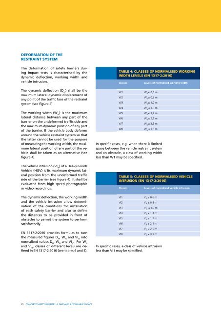
DEFORmATION OF THE<br />
RESTRAINT SYSTEm<br />
The deformation of <strong><strong>safe</strong>ty</strong> <strong>barriers</strong> during<br />
impact tests is characterised by the<br />
dynamic deflection, working width <strong>and</strong><br />
vehicle intrusion.<br />
The dynamic deflection (D m ) shall be the<br />
maximum lateral dynamic displacement of<br />
any point of the traffic face of the restraint<br />
system (see figure 4).<br />
The working width (W m ) is the maximum<br />
lateral distance between any part of the<br />
barrier on the undeformed traffic side <strong>and</strong><br />
the maximum dynamic position of any part<br />
of the barrier. If the vehicle body deforms<br />
around the vehicle restraint system so that<br />
the latter cannot be used for the purpose<br />
of measuring the working width, the maximum<br />
lateral position of any part of the vehicle<br />
shall be taken as an alternative (see<br />
figure 4).<br />
The vehicle intrusion (VI m ) of a Heavy Goods<br />
Vehicle (HGV) is its maximum dynamic lateral<br />
position from the undeformed traffic<br />
side of the barrier (see figure 4). It shall be<br />
evaluated from high speed photographic<br />
or video recordings.<br />
The dynamic deflection, the working width<br />
<strong>and</strong> the vehicle intrusion allow determination<br />
of the conditions for installation<br />
of each <strong><strong>safe</strong>ty</strong> barrier <strong>and</strong> also to define<br />
the distances to be provided in front of<br />
obstacles to permit the system to perform<br />
satisfactorily.<br />
EN 1317-2:2010 provides formulas to turn<br />
the measured figures D m , W m <strong>and</strong> VI m into<br />
normalised values D N , W N <strong>and</strong> VI N . For W N<br />
<strong>and</strong> VI N , classes of different levels are defined<br />
in EN 1317-2:2010 (see tables 4 <strong>and</strong> 5).<br />
13 CONCRETE SAFETY BARRIERS: A SAFE AND SUSTAINABLE CHOICE<br />
TABLE 4: CLASSES OF NORmALISED wORkINg<br />
wIDTH LEvELS (EN 1317-2:2010)<br />
Classes Levels of normalised working width<br />
W1 W ≤ 0,6 m<br />
N<br />
W2 W ≤ 0,8 m<br />
N<br />
W3 W ≤ 1,0 m<br />
N<br />
W4 W ≤ 1,3 m<br />
N<br />
W5 W ≤ 1,7 m<br />
N<br />
W6 W ≤ 2,1 m<br />
N<br />
W7 W ≤ 2,5 m<br />
N<br />
W8 W ≤ 3,5 m<br />
N<br />
In specific cases, e.g. when there is limited<br />
space between the vehicle restraint system<br />
<strong>and</strong> an obstacle, a class of working width<br />
less than W1 may be specified.<br />
TABLE 5: CLASSES OF NORmALISED vEHICLE<br />
INTRUSION (EN 1317-2:2010)<br />
Classes Levels of normalised vehicle intrusion<br />
VI1 VI ≤ 0,6 m<br />
N<br />
VI2 VI ≤ 0,8 m<br />
N<br />
VI3 VI ≤ 1,0 m<br />
N<br />
VI4 VI ≤ 1,3 m<br />
N<br />
VI5 VI ≤ 1,7 m<br />
N<br />
VI6 VI ≤ 2,1 m<br />
N<br />
VI7 VI ≤ 2,5 m<br />
N<br />
VI8 VI ≤ 3,5 m<br />
N<br />
In specific cases, a class of vehicle intrusion<br />
less than VI1 may be specified.