Gas Balanced Flue Guide - Euroheat
Gas Balanced Flue Guide - Euroheat
Gas Balanced Flue Guide - Euroheat

Create successful ePaper yourself
Turn your PDF publications into a flip-book with our unique Google optimized e-Paper software.
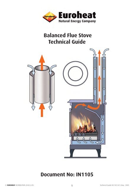
<strong>Balanced</strong> <strong>Flue</strong> Stove<br />
Technical <strong>Guide</strong><br />
Document No: IN1105<br />
© EUROHEAT DISTRIBUTORS (H.B.S) LTD. 1<br />
Technical <strong>Guide</strong> IN1105 Ed 5 May 2009
Hearth and Fireplace Requirements<br />
Do not be tempted to fit the stove into an unsuitable fireplace. Beyond the requirements<br />
of the building regulations and access to facilitate servicing the stove, providing a<br />
setting which will complement the stove is not a luxury, it is the practicality of making<br />
the most of an investment. A good builder will be able to transform even the most<br />
utilitarian of fireplaces, whether altering its proportions to those of the “Golden Mean”<br />
ideal, exposing a wooden lintel, stone or simply removing superfluous detailing for<br />
comparatively small costs, and the result will be a pleasure for many years.<br />
Minimum clearance<br />
from combustible<br />
materials<br />
Minimum clearance<br />
from non<br />
combustible<br />
materials<br />
A 12" 300mm** 9" 230mm<br />
B 6" 150mm** 4" 100mm<br />
C 1" 25mm** N/A<br />
D 2" 50mm** 2" 50mm<br />
E 6" 150mm** 4" 100mm<br />
F<br />
F<br />
E<br />
A<br />
12mm of non<br />
combustable material.<br />
12mm of non<br />
combustable material.<br />
Curtains and furnishings should be a minimum of<br />
1m from the stove.<br />
C<br />
B<br />
D<br />
“Golden Mean”<br />
Side Profile<br />
1/3 2/3<br />
“Golden Mean”<br />
Front View<br />
The stove can be placed on a combustible<br />
floor providing it can support the weight,<br />
and providing a non combustible hearth<br />
plinth with a minimum thickness of<br />
12mm is utilized.<br />
** The measurements provided are<br />
for guidance only.<br />
In all installations any surrounding<br />
flammable materials must not be allowed<br />
to exceed 80°C or a non combustible<br />
shield provided in accordance with<br />
current regulations. The stove must<br />
always stand perfectly level and have<br />
sufficient space allowing for service<br />
work.<br />
© EUROHEAT DISTRIBUTORS (H.B.S) LTD. 2<br />
Technical <strong>Guide</strong> IN1105 Ed 5 May 2009<br />
1<br />
2/3 2/3
<strong>Balanced</strong> <strong>Flue</strong> Systems<br />
A balanced flue system utilizes a double concentric pipe, the inner one taking away the products of combustion<br />
and the outer one bringing the air supply to the stove. This system allows a gas stove to be installed where no<br />
flue exists, and because the flue needs very little vertical height to operate, it is often possible to route the flue<br />
through the room wall to the outside.<br />
With all the air necessary for combustion being supplied through the outer pipe directly from the outside, the<br />
room in which the stove is installed needs no ventilation specifically for the stove.<br />
The balanced flue system has been designed to give a huge range of installation options, terminating either<br />
horizontally or vertically, as illustrated in the diagram below.<br />
Deciding on which form the balanced flue should take will very much be constrained by the termination of the<br />
flue. Building Regulations lay out definitive guide lines for where a flue can terminate, see the diagram later in<br />
this document, and if the building is listed there may be constraints on the position of any terminal and advice<br />
should be sort from the appropriate regulatory authority.<br />
© EUROHEAT DISTRIBUTORS (H.B.S) LTD. 3<br />
Technical <strong>Guide</strong> IN1105 Ed 5 May 2009
No Chimney ----- No Problem<br />
This document will help you design and your qualified engineer install a suitable balanced flue system for your<br />
stove. Following the simple guide lines will allow a balanced flued stove to be fitted in most situations where<br />
a conventionally flued stove could not be fitted.<br />
Top to Horizontal High Level <strong>Flue</strong> Kit<br />
It is not necessary for the stove to be situated against the outside wall through which the<br />
flue will pass, as the versatility of the balanced flue system can allow for considerable<br />
lengths of horizontal run of the flue.<br />
Top to Vertical High Level <strong>Flue</strong> Kit<br />
The vertical balanced flue system is ideal in situations such as in a newly constructed<br />
conservatory where there are no walls through which to pass a horizontal flue. The flue will<br />
rise from the stove vertically passing through the roof where it will then terminate with a<br />
vertical terminal.<br />
Minimum height 2m maximum 30m.<br />
Rear to Horizontal Low Level<br />
The low level horizontal kit is probably the simplest method of installation and allows<br />
you to fit the stove against any suitable outside wall in any room in your property.<br />
Maximum horizontal length 440mm, minimum length 310mm.<br />
Existing Chimney Adapter Kit<br />
The flue kits are also designed to be able to utilize an existing chimney. Properties<br />
which are designed with a high thermal efficiency may not allow an air brick<br />
to be fitted to supply air to a stove over 7kW input, the balanced flue stove<br />
overcomes this requirement as it is a sealed appliance.<br />
In some cases the top section of a chimney may have been removed and the<br />
versatility of the balanced flue system allows you to use what remains of the<br />
chimney using the chimney adapter kit.<br />
© EUROHEAT DISTRIBUTORS (H.B.S) LTD. 4<br />
Technical <strong>Guide</strong> IN1105 Ed 5 May 2009
Location of Outlets from <strong>Flue</strong>s Serving <strong>Gas</strong> <strong>Balanced</strong> <strong>Flue</strong> Stoves.<br />
Minimum Separation Distances for Terminals in mm<br />
Location <strong>Balanced</strong> <strong>Flue</strong><br />
A Below an opening Appliance<br />
rated heat<br />
input<br />
B Above an opening (1)<br />
0-7kw<br />
>7-14kw<br />
> 14-32kw<br />
>32<br />
0-32kw<br />
>32kw<br />
C Horizontally to an opening (1) 0-7kw<br />
>7-14kw<br />
>14kw<br />
D Below gutters, soil pipes or drain<br />
pipes<br />
300<br />
300<br />
600<br />
1500<br />
2000<br />
300<br />
600<br />
300<br />
400<br />
600<br />
E Below eaves 300<br />
Q Above the highest point of<br />
F Below balcony or car port roof<br />
600<br />
600<br />
intersection with the roof<br />
R <strong>Flue</strong> should not penetrate shaded area 600<br />
G From a vertical drain pipe or soil<br />
300<br />
pipe<br />
S <strong>Flue</strong> should not penetrate shaded area 200<br />
Note (1)<br />
An opening means an openable element, such as an openable window, or a fixed opening such as an air<br />
vent. However, in addition, the outlet should not be nearer than 300mm to an opening into the building fabric<br />
formed for the purpose of accommodating a built in element, such as a window frame.<br />
© EUROHEAT DISTRIBUTORS (H.B.S) LTD. 5<br />
Technical <strong>Guide</strong> IN1105 Ed 5 May 2009<br />
<br />
Minimum Separation Distances for Terminals in mm<br />
Location <strong>Balanced</strong> <strong>Flue</strong><br />
H From an internal or external corner<br />
or to a boundry alongside the<br />
terminal<br />
600<br />
I Above ground,roof or balcony level 300<br />
J From a surface or a boundary facing the<br />
terminal<br />
600<br />
K From a terminal facing the terminal 600<br />
L From an opening in the car port into the<br />
building<br />
M Vertically from a terminal on the same<br />
wall<br />
N Horizontally from a terminal on the<br />
same wall<br />
1200<br />
1200<br />
300<br />
P From a structure on the roof 1500
Calculating <strong>Flue</strong> Aspect Ratios<br />
The stove operates correctly only with air flow induced by the flue system being within the defined parameters.<br />
To achieve these, the vertical elements of the flue, which induce flue draught and increase the air supply to the<br />
stove, must be balanced against the horizontal elements of the flue, which offer resistance to flue draught and<br />
reduce the air supply to the stove.<br />
The ratio of vertical to horizontal lengths must be calculated to ensure the correct flue draught will be induced<br />
by the proposed flue.<br />
The difference in height between the top of the stove and the bottom of the terminal determines the vertical<br />
height to be used in the calculation. The flue run may necessitate the vertical elements to be separated by<br />
several horizontal runs, this is not important, only the total height gain is needed.<br />
The horizontal length is often more tedious to determine, but again, it is the total length which needs to be<br />
determined, regardless of their being continuous or in stages. Any 90 degree change of direction within the<br />
flue will offer resistance to flue draught and each change of direction will offer the same resistance to the flue<br />
draught as a horizontal run of 1000mm. For every 45 degree change in direction the resistance is that of a<br />
horizontal run of 500mm.<br />
BALANCED FLUE ASPECT RATIO DYNAMICS ILLUSTRATED<br />
6.0<br />
5.5<br />
5.0<br />
4.5<br />
4.0<br />
3.5<br />
3.0<br />
2.5<br />
2.0<br />
1.5<br />
1.0<br />
0.5<br />
0<br />
.5m vertical = 3.5m horizontal max.<br />
Depending on<br />
which direction your<br />
flue configuration<br />
will take and the<br />
model of the stove,<br />
a flue reduction<br />
plate (FRP) may<br />
or may not be<br />
required.<br />
See pages 24 & 25<br />
for details.<br />
1m vertical = 7m horizontal max.<br />
For 1m vertical rise a flue may have a maximum horizontal run of 7m.<br />
For each 90 degree bend introduced the horizontal run must be reduced by 1m.<br />
For each 45 degree bend introduced the horizontal run must be reduced by 500mm.<br />
0 0.5 1.0 1.5 2.0 2.5 3.0 3.5 4.0 4.5 5.0 5.5 6.0 6.5 7.0<br />
© EUROHEAT DISTRIBUTORS (H.B.S) LTD. 6<br />
Technical <strong>Guide</strong> IN1105 Ed 5 May 2009
Basic Principle of <strong>Balanced</strong> <strong>Flue</strong> Ratios Illustrated<br />
Top to Horizontal High Level<br />
1.5<br />
1.0<br />
0.5<br />
0<br />
1.5<br />
1.0<br />
0.5<br />
0<br />
0 0.5 1.0 1.5 2.0 2.5 3.0 3.5 4.0 4.5 5.0 5.5 6.0 6.5 7.0<br />
Example 'A'<br />
For a 1m vertical rise a flue can have a maximum of 7m horizontal length.<br />
0 0.5 1.0 1.5 2.0 2.5 3.0 3.5 4.0 4.5 5.0<br />
Example 'B'<br />
Rear to Horizontal Low Level<br />
Each additional 90 degree bend creates a draught resistance equal to 1m<br />
of horizontal length.<br />
Therefore in example 'B' the introduction of 2 x 90 degree bends,<br />
in a horizontal plain, reduces the maximum horizontal length by 2m.<br />
Example 'C'<br />
<strong>Flue</strong> spigot<br />
0 Min 310mm/ Max 440mm<br />
The rear exit flue may have a maximum horizontal run of 440mm<br />
from the flue spigot, the minimum length 310mm.<br />
© EUROHEAT DISTRIBUTORS (H.B.S) LTD. 7<br />
Technical <strong>Guide</strong> IN1105 Ed 5 May 2009
Example 1: Top to Horizontal High Level Kit<br />
Using the standard top to horizontal high level flue kit only.<br />
Standard kit starter<br />
length T1<br />
Components used<br />
Standard kit 90<br />
degree long bend<br />
Description Part No.<br />
Top to 150mm 180mm<br />
HorizontalHigh<br />
Level Kit<br />
MS91102 MS91103<br />
Sleeve liner MS91065 MS91066<br />
Terminal<br />
guard<br />
FP767 FP767<br />
Closure bezel MS91033 MS91040<br />
Ceramic rope or<br />
Fraxfill sealant to<br />
prevent draughts<br />
Closure<br />
bezel<br />
<br />
Minimum<br />
50mm<br />
Cavity wall<br />
The closure<br />
bezel fits around<br />
the flue pipe<br />
covering the<br />
hole through<br />
a solid wall<br />
giving the<br />
installation<br />
a clean finish<br />
both inside and<br />
outside.<br />
12mm<br />
Standard kit<br />
terminal length T2<br />
Sleeve kit<br />
(accessory)<br />
Terminal guard<br />
(accessory)<br />
Solid wall<br />
© EUROHEAT DISTRIBUTORS (H.B.S) LTD. 8<br />
Technical <strong>Guide</strong> IN1105 Ed 5 May 2009
Example 2: Top to Horizontal High Level Kit<br />
Taking the attached diagram as an example we can calculate the flue parameters for a top to horizontal flue<br />
system.<br />
Total Height = A<br />
Total Horizontal = B<br />
In this example<br />
A = 2.8 Metres B = 1.75 Metres<br />
Three x 90 degree bends have been used one of which (C) is the standard supply kit bend. This bend is ignored<br />
from the calculation as it is presumed it will always be used. The two remaining 90 degree bends increase the<br />
horizontal length by two metres.<br />
(one metre extra horizontal length per additional 90 degree bend).<br />
Total Height A = 2.8 Metres<br />
Total Horizontal B = 1.0 Metres<br />
In this example there is sufficient vertical rise for the horizontal run, as shown in the graph on page 6.<br />
Components used<br />
Standard kit<br />
terminal length<br />
T2<br />
Accessory 250mm<br />
length within wall<br />
Accessory short<br />
90 O bend<br />
Accessory 1metre length<br />
Wall band<br />
Accessory short<br />
90 O bend<br />
Description Part No. Quantity<br />
Top to 150mm 180mm<br />
HorizontalHigh<br />
Level Kit<br />
MS91102 MS91103<br />
1<br />
1 metre length MS91028 MS91034 1<br />
500mm length MS91029 MS91035 2<br />
250mm length MS91030 MS91036 1<br />
90° short bend MS91031 MS91037 2<br />
Wall band MS91052 MS91053 1<br />
B<br />
B+B= Total Horizontal<br />
A Total height<br />
Standard kit<br />
long 90 O bend<br />
Accessory<br />
500mm length<br />
Standard kit<br />
starter length<br />
T1<br />
© EUROHEAT DISTRIBUTORS (H.B.S) LTD. 9<br />
Technical <strong>Guide</strong> IN1105 Ed 5 May 2009<br />
A<br />
B
Example 3: Top to Vertical High Level Kit<br />
The ratio of vertical to horizontal lengths must be calculated to ensure the correct flue draught will be induced<br />
by the proposed flue. Taking the ratio diagram as an example we can calculate the flue parameters for a top<br />
to vertical flue system.<br />
Total Height = A<br />
Total Horizontal = B<br />
In this example<br />
A = 3.5 Metres B = 1.5 Metres<br />
Two x 90deg bends have been used. The two 90 degree bends increase the horizontal length by two metres.<br />
(One metre extra horizontal length per additional 90 degree bend).<br />
Total height A = 3.5 Metres<br />
Total Horizontal B =0.9 Metres<br />
In this example there is sufficient vertical rise for the horizontal run, as shown in the illustration on page 6.<br />
<br />
<br />
<br />
<br />
<br />
<br />
<br />
<br />
<br />
<br />
<br />
<br />
<br />
<br />
<br />
<br />
<br />
<br />
<br />
<br />
<br />
(accessory)<br />
<br />
(accessory)<br />
<br />
<br />
Components used<br />
Description Part No. Quantity<br />
Top to Vertical<br />
High Level Kit<br />
150mm<br />
MS91100<br />
180mm<br />
MS91101<br />
1<br />
1 metre length MS91028 MS91034 1<br />
500mm length MS91029 MS91035 3<br />
90° short bend MS91031 MS91037 2<br />
Wall band MS91052 MS91053 2<br />
© EUROHEAT DISTRIBUTORS (H.B.S) LTD. 10<br />
Technical <strong>Guide</strong> IN1105 Ed 5 May 2009
Example 4: Top to Vertical High Level Kit<br />
This example incorporates two 45 degree bends, a situation commonly encountered when having to route flue<br />
pipe around an obstacle such as a beam. When calculating the horizontal run the 45 degree bends equate to<br />
an additional 500mm per bend.<br />
Taking the ratio diagram as an example we can calculate the flue parameters for a top to vertical flue system.<br />
Total Height = A<br />
Total Horizontal = B<br />
In this example<br />
A = 4.5 Metres B = 1.5 Metres<br />
2 x 45deg bends have been used. The two 45 degree bends increase the horizontal length by one metre.<br />
(500mm extra horizontal length per 45 degree bend).<br />
Total height A = 4.5 Metres<br />
Total Horizontal B = 2.0 Metres<br />
In this example there is sufficient vertical rise for the horizontal run, as shown in the illustration on page 6.<br />
<br />
<br />
<br />
<br />
<br />
<br />
<br />
<br />
<br />
<br />
<br />
<br />
<br />
<br />
<br />
<br />
<br />
<br />
<br />
<br />
<br />
<br />
<br />
<br />
<br />
<br />
<br />
<br />
<br />
<br />
<br />
(accessory)<br />
Components used<br />
Description Part No. Quantity<br />
Top to Vertical<br />
High Level Kit<br />
150mm<br />
MS91100<br />
180mm<br />
MS91101<br />
1<br />
1 metre length MS91028 MS91034 5<br />
Adjustable<br />
length<br />
MS91045 MS91046 1<br />
45° short bend MS91054 MS91055 2<br />
Wall band MS91052 MS91053 5<br />
Roof flashing MS91063 MS91063 1<br />
© EUROHEAT DISTRIBUTORS (H.B.S) LTD. 11<br />
Technical <strong>Guide</strong> IN1105 Ed 5 May 2009
Example 5: Top to Vertical High Level Kit<br />
The minimum vertical height for a top to vertical flue is two meters of flue and the top to vertical kit<br />
components.<br />
Components used<br />
Description Part No. Quantity<br />
Top to Vertical<br />
High Level Kit<br />
150mm<br />
MS91100<br />
180mm<br />
MS91101<br />
1<br />
1 metre length MS91028 MS91034 2<br />
Wall band MS91052 MS91053 2<br />
Roof flashing MS91063 MS91063 1<br />
<br />
<br />
<br />
<br />
<br />
<br />
<br />
<br />
<br />
<br />
(accessory)<br />
<br />
<br />
© EUROHEAT DISTRIBUTORS (H.B.S) LTD. 12<br />
Technical <strong>Guide</strong> IN1105 Ed 5 May 2009
Example 6: Through Ceilings and Roof Spaces<br />
Fitting a Top to Vertical High Level <strong>Flue</strong> Kit Through Ceilings and Roof Spaces<br />
When installing balanced flue pipe through a ceiling the use of a ceiling support and fire stop spacer are<br />
recommended. There should be no flue joints at any point as the flue passes through a ceiling.<br />
There should a minimum clearance of 25mm from the flue pipe to any combustible material.<br />
No flue joints<br />
between fire<br />
stop spacer<br />
and ceiling<br />
support.<br />
Components used<br />
Weight of flue<br />
supported here.<br />
Ceiling support<br />
Fire stop spacer<br />
Weight of flue<br />
supported here.<br />
Description 150mm 180mm<br />
Ceiling support MS91056 MS91057<br />
Fire stop spacer MS91058 MS91059<br />
Roof flashing MS91063 MS91063<br />
Wall band MS91052 MS91053<br />
Roof flashing<br />
(accessory)<br />
<br />
© EUROHEAT DISTRIBUTORS (H.B.S) LTD. 13<br />
Technical <strong>Guide</strong> IN1105 Ed 5 May 2009
Example 7: Existing Chimney Adapter Kit Vertical Termination<br />
Fitting an Existing Chimney Adapter Kit in Conjunction with a High Level Vertical Kit<br />
There are great advantages in converting an existing chimney into a balanced flue. The existing chimney<br />
adapter kit can convert either ceramic lined chimneys or an unlined chimney into a balanced flue system. By<br />
using this system combustion air is drawn from the outside rather than from the property greatly increasing<br />
overall efficiency.<br />
In addittion many houses chimney stacks have been removed and the<br />
roof tiled over. They are usually capped off at attic floor level.<br />
We have developed a kit which can bring these chimneys back to life<br />
using a gas balanced flue stove.<br />
It can also be used in modern properties which have heat<br />
replacement systems where normal ventilation requirements<br />
cannot be applied.<br />
The system requires the use of two flexible flue liners, one to run<br />
inside the other mimicking the standard balanced flue pipe.<br />
The inside pipe is for the evacuation of the products of<br />
combustion and the outer is the air supply for combustion.<br />
It is imperative that all the joints are sealed<br />
to make them air tight.<br />
There follows two examples of the system,<br />
one is showing an existing chimney breast<br />
and the system terminating in a<br />
vertical position (through the roof).<br />
The second is showing the<br />
system terminating in a horizontal<br />
position (through a gable end of<br />
a property perhaps).<br />
Using two sizes of flue liner to<br />
mimic the balanced flue pipe.<br />
Ensure the seal is tight<br />
to the adapter kit<br />
<strong>Flue</strong> system<br />
size<br />
Inner liner Outer liner<br />
150mm 101mm / 4” 153mm / 6”<br />
180mm 125mm / 5“ 178mm / 7”<br />
<br />
<br />
<br />
<br />
<br />
<br />
<br />
<br />
<br />
<br />
<br />
<br />
<br />
<br />
<br />
<br />
Existing chimney<br />
top adapter<br />
Existing chimney<br />
bottom adapter<br />
Depending on which direction your flue configuration will take and the model of the stove, a reduction plate<br />
may or may not be required. See pages 24 & 25 for details.<br />
© EUROHEAT DISTRIBUTORS (H.B.S) LTD. 14<br />
Technical <strong>Guide</strong> IN1105 Ed 5 May 2009
Example 8: Existing Chimney Adapter Kit Horizontal Termination<br />
Fitting an Existing Chimney Adapter Kit in Conjunction with a Top to Horizontal Kit<br />
If this orientation is to be used then the standard 90 degree long bend from the top to horizontal kit MUST be<br />
used so that the last union before the terminal length T2 is a female (F) end.<br />
Existing chimney top adapter<br />
Existing chimney bottom adapter<br />
<strong>Flue</strong> system<br />
size<br />
Inner liner Outer liner<br />
150mm 101mm / 4” 153mm / 6”<br />
180mm 125mm / 5“ 178mm / 7”<br />
Existing chimney top adapter<br />
350mm<br />
95mm<br />
75mm<br />
100mm<br />
Accessory 1<br />
metre length<br />
Standard kit<br />
90° long bend<br />
Standard kit<br />
starter length<br />
T1<br />
Clay<br />
liner<br />
Flexible<br />
liner<br />
Standard kit<br />
terminal length<br />
T2<br />
Existing chimney bottom adapter<br />
350mm<br />
75mm<br />
The example above is showing an existing chimney adapter kit utilizing a existing clay liner, using a flexible<br />
liner to run inside the clay liner in order to expel the products of combustion but using the clay liner for the<br />
feed of combustion air. Ensure that the seals between flexible liner and the adapter are sound and the seal<br />
between the clay liner and the adapter are also sound.<br />
It can go through the long 90° bend (in the top to horizontal kit) and terminate through the gable end of the<br />
property.<br />
© EUROHEAT DISTRIBUTORS (H.B.S) LTD. 15<br />
Technical <strong>Guide</strong> IN1105 Ed 5 May 2009<br />
M<br />
F<br />
T1<br />
M<br />
F<br />
T2
Example 9: Through a Combustible Roof<br />
Installation of Top to Vertical High Level <strong>Balanced</strong> <strong>Flue</strong> Pipe Through a Combustible Roof<br />
A 25mm gap of non combustible material must be used when you are passing the balanced flue pipe through<br />
any combustible material.<br />
Conservatories can “come alive” with the installation of a stove, but care should be taken when installing a<br />
stove into a conservatory because the modern ones can be made entirely from plastic (or PVC). Advise from<br />
your conservatory installer/manufacturer should be sought.<br />
The flue system should be supported.<br />
600mm<br />
600mm<br />
600mm<br />
© EUROHEAT DISTRIBUTORS (H.B.S) LTD. 16<br />
Technical <strong>Guide</strong> IN1105 Ed 5 May 2009
Frequently Asked Questions<br />
Q. Can the stove be flued directly off the back?<br />
A. Yes, using the standard low level horizontal kit.<br />
Q. Can I use a bend directly off the top of the stove?<br />
A. No, the stove adapter is only designed to fit the telescopic starter length and straight lengths, bends will not<br />
seal to the flue outlet.<br />
Q. Can I fit the stove in the corner of a room?<br />
A. Yes, there is no problem in doing this using the top to horizontal flue kit, but it must be remembered that if<br />
the corner is also the corner of the property that the termination must be 600mm from any corner. See diagram<br />
page 5.<br />
Q. Can the vertical flue be passed through a combustible roof, such as a polycarbonate roof in a conservatory?<br />
A. Yes, as long as allowances are made for the type of roofing material and suitable insulation is provided. See<br />
the section on flueing through a combustible roof.<br />
Q. Can the stove be fitted into a bedroom?<br />
A. Yes, the stoves are room sealed and below 14kW input.<br />
Q. Can I cut the lengths of flue pipe?<br />
A. Yes, however the differential between the inner and outer length has to be maintained. It would be preferable<br />
to use an adjustable length<br />
Q. Does the flue terminal need to be guarded?<br />
A. If the flue terminal is to be sited less than two meters above level ground,<br />
a balcony or a flat roof where people have access, a guard must be fitted. Local<br />
by-laws may also require a further minimum height where the terminal is sited<br />
adjoining a public footpath.<br />
Q. If I have a high level horizontal kit can I then terminate it vertically?<br />
A. Yes, there is a vertical terminal with a crimped end which will fit to the<br />
flue system.<br />
Q. Do I need an air brick or other ventilation for supplying free air to the<br />
stove?<br />
A. No, the stove is room sealed and does not have any requirement for free<br />
air.<br />
Q. Does it matter how far out of the wall the terminal is fitted on a horizontal flue kit?<br />
A. Yes, there should be 12mm of flue pipe visible before the start of the flue terminal. Any greater length can<br />
upset the balanced flues operation.<br />
Q. What colours are the flue pipe available in?<br />
A. The flue pipe is supplied in one colour, a matt grey finish, which closely matches the cast finished stoves and<br />
complements the enamel finished stove. It is possible to change the colour using heat resistant paint.<br />
Q. To what wind speed are the terminals tested to?<br />
A. The maximum wind used is 12.5 m/s with 10% error. (28mph).<br />
Vertical terminal with<br />
crimped end<br />
Size Part No:<br />
150mm MS91047<br />
180MM MS91048<br />
Q. What is the maximum length the flue can travel horizontaly from the rear outlet of the stove?<br />
A. The standard low level horizontal flue kit gives a maximum extension of 440mm. No additional lengths or<br />
bends should be fitted.<br />
© EUROHEAT DISTRIBUTORS (H.B.S) LTD. 17<br />
Technical <strong>Guide</strong> IN1105 Ed 5 May 2009
Components of Top to Horizontal High Level Kit<br />
150mm kit MS91102<br />
180mm kit MS91103<br />
This is a high level horizontal flue kit. Other sections may be added to achieve the desired termination. For<br />
additional lengths and accessories see pages 21 to 23.<br />
<br />
Telescopic terminal length<br />
(T2)<br />
<br />
<br />
<br />
<br />
<br />
T2<br />
<br />
<br />
<br />
<br />
<br />
<br />
Clamp band<br />
Telescopic starter length (T1)<br />
which must be used as the<br />
first length of flue pipe from<br />
the stoves flue collar<br />
Dimensions of standard 150mm flue kit<br />
90° Long bend<br />
© EUROHEAT DISTRIBUTORS (H.B.S) LTD. 18<br />
Technical <strong>Guide</strong> IN1105 Ed 5 May 2009<br />
T1<br />
T1<br />
Dimensions of standard 180mm flue kit<br />
Max: 555mm<br />
Min: 470mm<br />
The min can be reduced further by cutting 40mm<br />
off the T2 section<br />
T2<br />
12mm<br />
Max 555mm<br />
Min 445mm<br />
The min can be reduced<br />
further by cutting 40mm<br />
off the T1 section
Components of Top to Vertical High Level Kit<br />
150mm kit MS91100<br />
180mm kit MS91101<br />
This kit is used when the installation requires the termination to be through a roof. Further components will<br />
be required with this kit. For additional lengths and accessories see pages 21 to 24.<br />
200mm<br />
250mm<br />
T1<br />
Adjustable Starter Pipe<br />
Toatal length Minimum Length<br />
for Calculations<br />
Vertical Terminal<br />
Locking Band<br />
Adjustable Starter Pipe<br />
Maximum Length<br />
For Calculations<br />
250mm 30mm 170mm<br />
© EUROHEAT DISTRIBUTORS (H.B.S) LTD. 19<br />
Technical <strong>Guide</strong> IN1105 Ed 5 May 2009
Components of Rear to Horizontal Low Level Kit<br />
150mm kit MS91097<br />
180mm kit MS91098<br />
Only the standard kit may be used, additional bends and lengths MUST not be used as they will adversely<br />
effect the performance of the balanced flue and could be dangerous.<br />
Telescopic Module<br />
(horizontal adjustable)<br />
T1<br />
Maximum<br />
Length 440 mm<br />
Minimum<br />
Length 310 mm<br />
Spacers and self tapping<br />
screws for wind shield<br />
Horizontal<br />
Terminal<br />
Terminal Guard<br />
Wind shield<br />
© EUROHEAT DISTRIBUTORS (H.B.S) LTD. 20<br />
Technical <strong>Guide</strong> IN1105 Ed 5 May 2009
Additional <strong>Flue</strong> Pipe System Accessories<br />
Each section of additional flue pipe is<br />
supplied with a locking band.<br />
1 metre pipe<br />
500mm pipe<br />
250mm pipe<br />
90 degree short bend<br />
45 degree short bend<br />
Adjustable length 250mm<br />
Wall Band<br />
When calculating the amount of flue pipe required the usable length and not the overall length should be<br />
used, see the table below.<br />
Description 150mm 180mm Over all length Useable length<br />
1 metre pipe MS91028 MS91034 1m 960mm<br />
500mm pipe MS91029 MS91035 500mm 460mm<br />
250mm pipe MS91030 MS91036 250mm 210mm<br />
90 Degree bend MS91031 120mm vertical 170mm horizontal<br />
90 Degree bend MS91037 246mm vertical 186mm horizontal<br />
Adjustable pipe MS91045 MS91046 195 max length 85 min length<br />
45 Degree bend MS91054 MS91055 170mm vertical 75mm horizontal<br />
2 x 45 Degree bend<br />
off set<br />
MS91054 x 2 MS91055 x 2 340mm 150mm off set<br />
Wall band MS91052 MS91053<br />
© EUROHEAT DISTRIBUTORS (H.B.S) LTD. 21<br />
Technical <strong>Guide</strong> IN1105 Ed 5 May 2009
Additional <strong>Flue</strong> System Accessories<br />
Ceiling Support & Fire Stop Spacers<br />
Required when a balanced flue kit passes through a ceiling.<br />
Fire Stop<br />
Description Part No. 150mm Part No. 180mm<br />
Ceiling Support MS91056 MS91057<br />
Fire Stop MS91058 MS91059<br />
Existing Chimney Adapter Kit<br />
Allows an existing sound chimney to be used as part of the balanced flue.<br />
Description Part No. 150mm Part No. 180mm<br />
Existing Chimney Adapter Kit MS91085 MS91086<br />
Sleeve Liner<br />
Required when flue pipe passes through a cavity wall. It can be cut down to size or an extender sleeve added.<br />
Max 360mm<br />
Min 240mm<br />
Outer diameter<br />
150mm kit 165mm<br />
180mm kit 195mm<br />
Extender sleeve<br />
Ceiling Support<br />
Description Part No. 150mm Part No. 180mm<br />
Sleeve Liner MS91065 MS91066<br />
Extender sleeve MS91067 MS91068<br />
© EUROHEAT DISTRIBUTORS (H.B.S) LTD. 22<br />
Technical <strong>Guide</strong> IN1105 Ed 5 May 2009<br />
Cavity
Additional <strong>Flue</strong> System Accessories<br />
Roof Flashing<br />
Required when a balanced flue kit passes through the surface of a roof,<br />
flat or pitched.<br />
Roof Flashing<br />
Description Part No. 150mm kits Part No. 180mm kits<br />
Roof Flashing MS91063 MS91063<br />
Terminal Guard<br />
The terminal guard is suitable for High-Level Top to Horizontal kits only. The flue outlet should be protected<br />
with a guard if persons could come into contact with it or if it could become damaged. If a flue outlet is in a<br />
vunerable position, such as where the flue discharges within reach of the ground (less than 2m), or a balcony,<br />
veranda or an opening window.<br />
Terminal Guard Closure Bezel<br />
Closure Bezel<br />
The closure bezel fits around the flue pipe covering the hole through the wall and gives the installation a clean<br />
finish.<br />
Description Part No. 150mm kits Part No. 180mm kits<br />
Closure Bezel MS91033 MS91040<br />
Terminal Guard FP767 FP767<br />
Fraxfill<br />
Fraxfill is a pliable (tacky putty)<br />
white ceramic fibre gap fill supplied<br />
in a 300g cartridge for use with a<br />
sealant gun. Fraxfill is recommended<br />
for applications with operating<br />
temperatures of up to 1200°C.<br />
<br />
Description Part No. 150mm kits Part No. 180mm kits<br />
Fraxfill MS9045 MS9045<br />
© EUROHEAT DISTRIBUTORS (H.B.S) LTD. 23<br />
Technical <strong>Guide</strong> IN1105 Ed 5 May 2009
<strong>Flue</strong> Reduction Plate (FRP)<br />
Before Installation<br />
Depending on which direction your flue configuration will take, a reduction plate may or may not be<br />
required.<br />
The choke plate is a circular plate which fits under the inner flue connection.<br />
The list below will advise which FRP will or will not be needed.<br />
Harmony 15 Stanford 15 (H15 & S15)<br />
Description Fuel Type FRP<br />
Top to horizontal high level kit with<br />
standard flue kit<br />
Top to vertical high level kit<br />
Rear to horizontal low level kit<br />
Natural<br />
<strong>Gas</strong><br />
58mm<br />
LPG 58mm<br />
Natural<br />
<strong>Gas</strong><br />
40mm<br />
LPG 45mm<br />
Natural<br />
<strong>Gas</strong><br />
No FRP<br />
LPG No FRP<br />
Harmony 25 Stanford 25 (H25 & S25)<br />
Description Fuel Type FRP<br />
Top to horizontal high level kit with<br />
standard flue kit<br />
Top to vertical high level kit<br />
Rear to horizontal low level kit<br />
Natural<br />
<strong>Gas</strong><br />
66mm<br />
LPG 66mm<br />
Natural<br />
<strong>Gas</strong><br />
50mm<br />
LPG 50mm<br />
Natural<br />
<strong>Gas</strong><br />
No FRP<br />
LPG No FRP<br />
© EUROHEAT DISTRIBUTORS (H.B.S) LTD. 24<br />
Technical <strong>Guide</strong> IN1105 Ed 5 May 2009
Top flue connection for top to horizontal<br />
high level kit and top to vertical kit<br />
Harmony 35 (H35)<br />
Description Fuel Type FRP<br />
Top to horizontal high level kit with<br />
standard flue kit<br />
Top to vertical high level kit<br />
Rear to horizontal low level kit<br />
Natural<br />
<strong>Gas</strong><br />
76mm<br />
LPG No FRP<br />
Natural<br />
<strong>Gas</strong><br />
55mm<br />
LPG 55mm<br />
Natural<br />
<strong>Gas</strong><br />
No FRP<br />
LPG No FRP<br />
Harmony 45 (H45)<br />
Description Fuel Type FRP<br />
Top to horizontal high level kit with<br />
standard flue kit<br />
Top to vertical high level kit<br />
Rear to horizontal low level kit<br />
Natural<br />
<strong>Gas</strong><br />
70mm<br />
LPG 70mm<br />
Natural<br />
<strong>Gas</strong><br />
70mm<br />
LPG 70mm<br />
Natural<br />
<strong>Gas</strong><br />
No FRP<br />
LPG No FRP<br />
Rear flue connection for rear to<br />
horizontal low level kit<br />
© EUROHEAT DISTRIBUTORS (H.B.S) LTD. 25<br />
Technical <strong>Guide</strong> IN1105 Ed 5 May 2009
Stove Technical Data<br />
Harmony 15<br />
150mm <strong>Flue</strong> kit system<br />
and accessories<br />
Harmony 25<br />
150mm <strong>Flue</strong> kit system<br />
and accessories<br />
Harmony 35<br />
180mm <strong>Flue</strong> kit system<br />
and accessories<br />
Harmony 45<br />
180mm <strong>Flue</strong> kit system<br />
and accessories<br />
Stanford 15<br />
150mm <strong>Flue</strong> kit system<br />
and accessories<br />
Stanford 25<br />
150mm <strong>Flue</strong> kit system<br />
and accessories<br />
<br />
<br />
<br />
<br />
435<br />
455<br />
<br />
<br />
<br />
<br />
<br />
<br />
<br />
<br />
<br />
<br />
<br />
<br />
<br />
<br />
<br />
<br />
240<br />
<br />
150 ID<br />
<br />
<br />
<br />
160<br />
270<br />
120<br />
150ID<br />
150mm <strong>Flue</strong> kit Part No.<br />
Top to horizontal<br />
high level kit<br />
MS91102<br />
Top to vertical high<br />
level kit<br />
MS91100<br />
Rear to horizontal<br />
low level kit<br />
MS91097<br />
180mm <strong>Flue</strong> kit Part No.<br />
Top to horizontal<br />
high level kit<br />
MS91103<br />
Top to vertical high<br />
level kit<br />
MS91101<br />
Rear to horizontal<br />
low level kit<br />
MS91098<br />
© EUROHEAT DISTRIBUTORS (H.B.S) LTD. 26<br />
Technical <strong>Guide</strong> IN1105 Ed 5 May 2009<br />
495<br />
600<br />
565<br />
<br />
<br />
<br />
670<br />
682<br />
<br />
750<br />
150mm <strong>Flue</strong> kit Part No.<br />
Top to horizontal<br />
high level kit<br />
MS91102<br />
Top to vertical high<br />
level kit<br />
MS91100<br />
Rear to horizontal<br />
low level kit<br />
MS91097<br />
180mm <strong>Flue</strong> kit Part No.<br />
Top to horizontal<br />
high level kit<br />
MS91103<br />
Top to vertical high<br />
level kit<br />
MS91101<br />
Rear to horizontal<br />
low level kit<br />
MS91098<br />
150mm <strong>Flue</strong> kit Part No.<br />
Top to horizontal<br />
high level kit<br />
MS91102<br />
Top to vertical high<br />
level kit<br />
MS91100<br />
Rear to horizontal<br />
low level kit<br />
MS91097<br />
150mm <strong>Flue</strong> kit Part No.<br />
Top to horizontal<br />
high level kit<br />
MS91102<br />
Top to vertical high<br />
level kit<br />
MS91100<br />
Rear to horizontal<br />
low level kit<br />
MS91097
Fitting High Level Horizontal <strong>Flue</strong> Kit<br />
The flue system starter length should be sealed to the stove’s flue spigot with a heat proof sealant, (we<br />
suggest “fraxfill”, part number MS9045). Apply a bead of heat resistant sealant to the inner face of the outer<br />
flue spigot and the outer face of the inner flue pipe. The clamp should be used to secure the first elbow or<br />
additional length and the appropriate heat proof tape used to secure the telescopic fitting.<br />
Heat proof<br />
sealant<br />
Heat proof<br />
sealant<br />
<br />
Where the flue passes through<br />
a cavity wall, the hole must be<br />
sleeved for its entire length.<br />
Accessory 90°<br />
short bend<br />
<br />
<br />
<br />
Standard kit<br />
90° long bend<br />
<br />
<br />
Wall band<br />
The guide giving the permitted flue configurations must<br />
be consulted to verify that a proposed flue is possible. The<br />
“long 90° bend” supplied as standard with the stove must be<br />
incorporated into the system to ensure a non crimped end at<br />
the last fitting before the termination length T2.<br />
All joints between the fixed lengths of flue must<br />
be secured with locking bands, and every meter in<br />
length horizontally or vertically must be supported.<br />
It is your responsibility to ensure that no part of the<br />
flue installation contravenes any gas or building<br />
regulations.<br />
<br />
© EUROHEAT DISTRIBUTORS (H.B.S) LTD. 27<br />
Technical <strong>Guide</strong> IN1105 Ed 5 May 2009<br />
<br />
<br />
<br />
Standard kit<br />
90° long bend<br />
Accessory 90°<br />
short bend<br />
Locking band
Position of <strong>Flue</strong> Terminal on Outside Wall<br />
The position of the terminal on the outside wall should be 12mm from<br />
the edge of the terminal mesh to the face of the outside wall.<br />
If it protrudes further than 12mm it may be adversely affected by wind<br />
blowing across the terminal so upsetting the balanced flue operation.<br />
If it is fitted with less than 12mm clearance then the vented exhaust<br />
gases may be drawn back into the balanced flue primary air inlet so<br />
adversely effecting the operation of the balanced flue.<br />
The flue pipe passing through the wall should be angled slightly<br />
downwards (1 degree) towards the terminal so as to stop rain water<br />
entering and passing along the flue.<br />
Horizontal <strong>Flue</strong> Passing Through a Combustible or Cavity Wall<br />
Ceramic rope or<br />
Fraxfill sealant to<br />
prevent draughts<br />
25mm air gap<br />
incorporated as part<br />
of the <strong>Flue</strong> System<br />
Sleeve liner<br />
T1<br />
50mm<br />
minimum<br />
12mm<br />
© EUROHEAT DISTRIBUTORS (H.B.S) LTD. 28<br />
Technical <strong>Guide</strong> IN1105 Ed 5 May 2009<br />
T2<br />
1° incline<br />
Seal the bezel part of sleeve liner<br />
to the outer face of the wall using<br />
a suitable sealant<br />
Sleeve liner<br />
12mm<br />
Ceramic rope or<br />
Fraxfill sealant to<br />
prevent draughts
Fitting the High Level Vertical <strong>Flue</strong> Kit<br />
The flue system starter length should be sealed to the stove’s flue spigot with a heat proof sealant,(we suggest<br />
“fraxfill”, part number MS9045). Apply a bead of heat resistant sealant to the inner face of the outer flue spigot<br />
and the outer face of the inner flue pipe. The clamp should be used to secure the first elbow or additional<br />
length and the appropriate heat proof tape used to secure the telescopic fitting.<br />
Heat proof<br />
sealant<br />
Wall bands should be fitted<br />
to support the flue pipe.<br />
The telescopic starter length<br />
must be used so that the<br />
male end of the flue pipe<br />
connects to the vertical flue<br />
terminal.<br />
Accessory 90°<br />
short bend<br />
The vertical terminal will only fit<br />
the male end of the flue pipe.<br />
<br />
<br />
<br />
© EUROHEAT DISTRIBUTORS (H.B.S) LTD. 29<br />
Technical <strong>Guide</strong> IN1105 Ed 5 May 2009<br />
<br />
Heat proof<br />
sealant<br />
Accessory 90°<br />
short bend<br />
<br />
<br />
<br />
All joints between the fixed lengths of flue<br />
must be secured with locking bands, and<br />
every meter in length horizontally or vertically<br />
must be supported. It is your responsibility to<br />
ensure that no part of the flue installation<br />
contravenes any gas or building regulations.
Fitting the Low Level Horizontal <strong>Flue</strong> Kit<br />
The horizontal flue kit starter length should be secured by means of a self tapping screw. If it is to pass through<br />
a cavity wall then a sleeve liner (150mm part No. MS91065. 180mm part No. MS91066) should be fitted.<br />
The terminal section should be fitted with the snorkel pointing upwards and the wind shield to protect the<br />
terminal outlet. Only the standard kit may be used from the rear flue outlet.<br />
Secure starter length with<br />
a self tapping screw<br />
<strong>Flue</strong> should be sleeved if passing<br />
through a cavity wall<br />
Apply a bead of heat resistant sealant (we<br />
suggest “fraxfill”, part number MS9045) to the<br />
inner face of the outer flue spigot and the outer<br />
face of the inner flue pipe.<br />
Wind Shield<br />
The wind shield should be fitted using the spacers so that it baffles<br />
the top holes in the horizontal terminal to protect it from the<br />
effects of the wind. The top holes are pre-drilled into the terminal<br />
however in some cases the lower holes may need to be drilled to<br />
complete the installation.<br />
Terminal snorkle<br />
Sleeve kit<br />
150mm part No. MS91065<br />
180mm part No. MS91066<br />
The terminal length should be<br />
fitted with the snorkle pointing<br />
upwards.<br />
Fitting of <strong>Flue</strong> Spigot to Rear of the Stove<br />
Remove the inner and outer spigot from the top of the stove. Remove the rear blanking plate and fit the inner<br />
and outer spigots and the flue reduction plate (FRP) if required, see pages 23 and 24, to the rear of the stove.<br />
Fit the blanking plate onto the top plate.<br />
© EUROHEAT DISTRIBUTORS (H.B.S) LTD. 30<br />
Technical <strong>Guide</strong> IN1105 Ed 5 May 2009
Glossary of Terms<br />
Term Description<br />
Top to horizontal high level<br />
The flue kit rises from the top of the stove, it includes a long sweeping 90°<br />
bend and terminates through the side wall of a property.<br />
Top to vertical high level<br />
The flue kit rises from the top of the stove and terminates vertically through<br />
a roof.<br />
Low level horizontal<br />
The flue runs horizontally from the back of the stove and terminates through<br />
the side wall of a property.<br />
T1<br />
Telescopic starter length. The first section of the flue kit which can telescope<br />
into the section of flue to follow it. Top connection only.<br />
T2<br />
Telescopic terminal length. The last section of the top to horizontal flue kit<br />
which can telescope into the section of flue before it.<br />
FRP<br />
<strong>Flue</strong> reduction plate. A choke plate fitted into the outlet of the stove to<br />
reduce the velocity of the flue gases.<br />
Sleeve liner<br />
Telescopic sleeve, required when a flue passes through a combustible or<br />
cavity wall.<br />
Outlet<br />
Position of the flue terminal, which is governed by Building Regulations, see<br />
diagram on page 6.<br />
Terminal Fitted to the end of the flue system, supplied with the flue kits.<br />
Wall band Required to support every 1m in length vertically or horizontally of flue.<br />
Locking band<br />
Supplied in the kits and with every additional length of flue pipe to secure<br />
the joints between sections.<br />
Closure bezel<br />
The closure bezel fits around the flue pipe covering the hole through the<br />
wall and giving the installation a clean finish.<br />
A wire mesh guard required when the outlet is in a vulnerable position,<br />
Terminal guard such as where the flue discharges within reach of the ground (less than<br />
2m), or a balcony, verandah or a opening window.<br />
Required when a vertical flue passes through a roof. A vulcanised rubber<br />
Roof flashing gaiter through which the flue pipe passes allowing a water tight seal to be<br />
made.<br />
A metal plate with locking band required when a flue passes through a<br />
Ceiling support ceiling. Fitting onto the floor above the ceiling through which it passes with<br />
a clamp to secure it to the flue pipe and support the weight of the flue.<br />
Fire stop spacer<br />
A metal plate which fits on the ceiling through which the stove passes which<br />
is required to conform to Building Regulations.<br />
The existing chimney adapter kit can convert either ceramic lined chimneys<br />
Existing chimney adapter kit<br />
or an unlined chimney into a balanced flue system. By using this system<br />
combustion air is drawn from the outside rather than from within the<br />
property.<br />
Terminal snorkle<br />
The upturned inner pipe within the low level horizontal flue kit, that when<br />
fitted should be pointing upwards.<br />
This fits on the outside of the low level horizontal terminal, standing away<br />
Wind guard from the body of the terminal guard, with spacers, so protecting the top<br />
holes of the terminal from the effects of wind blowing directly on them.<br />
Fraxfill is a pliable (tacky putty) white ceramic fibre gap fill supplied in<br />
Fraxfill (MS9045) a 300g cartridge for use with a sealant gun. Fraxfill is recommended for<br />
applications with operating temperatures of up to 1200°C.<br />
© EUROHEAT DISTRIBUTORS (H.B.S) LTD. 31<br />
Technical <strong>Guide</strong> IN1105 Ed 5 May 2009
When installing the stove this documnet should be used in<br />
conjunction with <strong>Euroheat</strong>s Installation Instructions specific to the<br />
stove supplied.<br />
The gas stoves in the <strong>Euroheat</strong> range may only be installed by a<br />
suitably qualified <strong>Gas</strong> Safe technician using the appropriate fittings<br />
for the gas type being installed, and the stove must not be modified<br />
in anyway.<br />
Important<br />
The installer is responsible under the Health and Safety at Work Act 1974 vi the caustic nature of fire cement<br />
and the possibility of disturbing asbestos and other materials such as ceramic in existing installations and<br />
to suggest appropriate protection to be given to the person (s) carrying out the installation. The complete<br />
installation must be carried out with due reference to the British Standards, Codes of Practice and Building<br />
Regulations relevant to the fuel type being installed, and the manufacturers installation instructions.<br />
This document is a General Installation <strong>Guide</strong> only. It does not replace the installation instructions or building<br />
regulations. No installation should be undertaken unless the installer is suitably qualified.<br />
Information from the <strong>Euroheat</strong> Technical Team<br />
<strong>Euroheat</strong> and Nestor Martin have a policy of continual research and development and reserve the right to<br />
modify its appliances without prior notice.<br />
We make every effort to ensure that the information provided in this document is correct and accurate at<br />
the time of printing. Continued updates occur to adapt documents to customer requirements and appliance<br />
changes. For the latest editions of all <strong>Euroheat</strong> documentation visit our web site<br />
www.euroheat.co.uk.<br />
We would request that you inform <strong>Euroheat</strong> of information which you feel is not provided in this document<br />
which would assist other users in the future.<br />
The <strong>Euroheat</strong> Technical Team<br />
www.euroheat.co.uk<br />
<strong>Euroheat</strong> Distributors (H.B.S.). Ltd.,<br />
Unit 2, Court Farm Business Park,<br />
Bishops Frome, Reception: 01885 491100<br />
Worcestershire, Technical Support: 01885 491117<br />
WR6 5AYY. Email: tech@euroheat.co.uk<br />
© EUROHEAT DISTRIBUTORS (H.B.S) LTD. 32<br />
Technical <strong>Guide</strong> IN1105 Ed 5 May 2009